Corel DESIGNER User Guide X6 Instruction Manual DESIGNERX6 EN
User Manual: corel Corel Designer - X6 - Instruction Manual Free User Guide for Corel Designer Software, Manual
Open the PDF directly: View PDF ![]() .
.
Page Count: 987 [warning: Documents this large are best viewed by clicking the View PDF Link!]
- Table of contents
- Getting started
- Welcome
- What’s new in Corel DESIGNER X6?
- Learning resources
- Corel DESIGNER workspace tour
- Corel DESIGNER basics
- Understanding vector graphics and bitmaps
- Starting and opening drawings
- Acquiring images from scanners and digital cameras
- Undoing, redoing, and repeating actions
- Zooming, panning, and scrolling
- Previewing drawings
- Choosing viewing modes
- Working with views
- Saving drawings
- Backing up and recovering files
- Adding and accessing drawing information
- Closing drawings and quitting Corel DESIGNER
- Finding and managing content
- Working with precision
- Collaborating
- Lines, shapes, and outlines
- Working with lines, outlines, and brushstrokes
- Setting the default property values
- Drawing lines
- Closing multiple line segments
- Drawing callouts
- Drawing connector lines
- Drawing dimension lines
- Formatting lines and outlines
- Adding arrowheads to lines and curves
- Drawing calligraphic, pressure-sensitive, and preset lines
- Applying linear-pattern brushstrokes
- Spraying linear patterns along a line
- Drawing shapes
- Shaping objects
- Working with curve objects
- Shaping curve objects by using Reflect Nodes mode
- Cropping, splitting, and erasing objects
- Trimming objects
- Filleting, scalloping, and chamfering corners of curve objects
- Welding and intersecting objects
- Creating new objects from boundaries
- Creating PowerClip objects
- Smudging and smearing objects
- Adding twirl effects
- Roughening objects
- Shaping objects by attracting or pushing away nodes
- Applying distortion effects
- Shaping objects by using envelopes
- Reference: Shaping objects
- Projecting objects
- Working with lines, outlines, and brushstrokes
- Objects, symbols, and layers
- Working with objects
- Selecting objects
- Changing object properties
- Copying, duplicating, and deleting objects
- Copying object properties, transformations, and effects
- Cloning objects
- Moving objects
- Sizing and scaling objects
- Rotating objects
- Mirroring objects
- Skewing objects
- Aligning and distributing objects
- Changing the order of objects
- Grouping objects
- Combining objects
- Locking objects
- Finding and replacing objects
- Accessing and displaying geometric information about objects
- Inserting bar codes
- Working with symbols
- Creating objects for the Web
- Working with layers
- Object linking and embedding
- Working with object data
- Working with objects
- Color and fills
- Working with color
- Filling objects
- Using color management
- Understanding color management
- Getting started with color management in Corel DESIGNER
- Installing, loading, and embedding color profiles
- Assigning color profiles
- Converting colors to other color profiles
- Choosing color-conversion settings
- Soft proofing
- Working with color management presets
- Working with color management policies
- Managing colors when opening documents
- Managing colors when importing and pasting files
- Managing colors for print
- Using a safe CMYK workflow
- Managing colors for online viewing
- Special effects
- Text
- Adding and manipulating text
- Importing and pasting text
- Adding artistic text
- Adding paragraph text
- Adding columns to text frames
- Combining and linking paragraph text frames
- Aligning text by using the baseline grid
- Selecting text
- Finding, editing, and converting text
- Shifting, rotating, mirroring, and flipping text
- Moving text
- Wrapping text
- Fitting text to a path
- Embedding graphics and adding special characters
- Working with legacy text
- Formatting text
- Choosing typefaces and fonts
- Formatting characters
- Changing text color
- Kerning a range of characters
- Changing text case
- Working with OpenType features
- Adjusting character and word spacing
- Adjusting line and paragraph spacing
- Adding bullets to text
- Inserting drop caps
- Changing character position and angle
- Aligning text
- Adding tabs and indents
- Working with text styles
- Hyphenating text
- Inserting formatting codes
- Displaying nonprinting characters
- Working with text in different languages
- Managing fonts
- Using writing tools
- Adding and manipulating text
- Templates and styles
- Working with templates
- Working with styles and style sets
- Creating styles and style sets
- Applying styles and style sets
- Editing styles and style sets
- Managing default object properties
- Exporting and importing style sheets
- Assigning keyboard shortcuts to styles or style sets
- Finding objects that use a specific style or style set
- Breaking the link between objects and styles or style sets
- Working with color styles
- Pages and layout
- Working with pages and layout tools
- Working with tables
- Adding tables to drawings
- Selecting, moving, and navigating table components
- Inserting and deleting table rows and columns
- Resizing table cells, rows, and columns
- Formatting tables and cells
- Working with text in tables
- Converting tables to text
- Merging and splitting tables and cells
- Manipulating tables as objects
- Adding images, graphics, and backgrounds to tables
- Importing tables in a drawing
- Bitmaps
- Working with bitmaps
- Converting vector graphics to bitmaps
- Importing bitmaps
- Cropping bitmaps
- Changing the dimensions and resolution of bitmaps
- Straightening bitmaps
- Using Digimarc watermarks to identify bitmaps
- Removing dust and scratch marks from bitmaps
- Applying special effects in bitmaps
- Working with colors in bitmaps
- Using the Image Adjustment Lab
- Adjusting color and tone
- Using the Tone Curve filter
- Transforming color and tone
- Editing bitmaps with Corel PHOTO-PAINT
- Working with bitmap color modes
- Tracing bitmaps and editing traced results
- Working with RAW camera files
- Working with bitmaps
- Printing
- File formats
- Importing and exporting files
- Working with 3D models
- Exporting to PDF
- Exporting documents as PDF files
- Including hyperlinks, bookmarks, and thumbnails in PDF files
- Reducing the size of PDF files
- Working with text and fonts in PDF files
- Specifying an encoding format for PDF files
- Specifying a viewing option for EPS files
- Specifying color management options for exporting PDF files
- Setting security options for PDF files
- Optimizing PDF files
- Viewing preflight summaries for PDF files
- Preparing PDF files for a print provider
- Working with office productivity applications
- Exporting to HTML
- Supported file formats
- 3D file formats
- Adobe Illustrator (AI)
- Adobe Type 1 Font (PFB)
- Windows Bitmap (BMP)
- OS/2 Bitmap (BMP)
- Computer Graphics Metafile (CGM)
- CorelDRAW (CDR)
- Corel Presentation Exchange (CMX)
- Corel PHOTO-PAINT (CPT)
- Corel Symbol Library (CSL)
- Cursor Resource (CUR)
- Microsoft Word (DOC, DOCX, or RTF)
- Microsoft Publisher (PUB)
- Corel DESIGNER (DES, DSF, DS4, or DRW)
- AutoCAD Drawing Database (DWG) and AutoCAD Drawing Interchange Format (DXF)
- Encapsulated PostScript (EPS)
- PostScript (PS or PRN)
- GIF
- HTML
- JPEG (JPG)
- JPEG 2000 (JP2)
- Kodak Photo CD Image (PCD)
- PICT (PCT)
- PaintBrush (PCX)
- Adobe Portable Document Format (PDF)
- HPGL Plotter File (PLT)
- Portable Network Graphics (PNG)
- Adobe Photoshop (PSD)
- Corel Painter (RIF)
- Scalable Vector Graphics (SVG)
- Adobe Flash (SWF)
- TARGA (TGA)
- TIFF
- TrueType Font (TTF)
- Visio (VSD)
- WordPerfect Document (WPD)
- WordPerfect Graphic (WPG)
- RAW camera file formats
- Wavelet Compressed Bitmap (WI)
- Windows Metafile Format (WMF)
- Additional file formats
- Recommended formats for importing graphics
- Recommended formats for exporting graphics
- General notes on importing text files
- Customizing and automating
- Reference
- Index

Copyright © 2013 Corel Corporation. All rights reserved.
Corel DESIGNER® X6 User Guide
Product specifications, pricing, packaging, technical support and information
(“specifications”) refer to the retail English version only. The specifications for all other
versions (including other language versions) may vary.
Information is provided by Corel on an “as is” basis, without any other warranties or
conditions, express or implied, including, but not limited to, warranties of
merchantable quality, satisfactory quality, merchantability or fitness for a particular
purpose, or those arising by law, statute, usage of trade, course of dealing or otherwise.
The entire risk as to the results of the information provided or its use is assumed by you.
Corel shall have no liability to you or any other person or entity for any indirect,
incidental, special, or consequential damages whatsoever, including, but not limited to,
loss of revenue or profit, lost or damaged data or other commercial or economic loss,
even if Corel has been advised of the possibility of such damages, or they are foreseeable.
Corel is also not liable for any claims made by any third party. Corel’s maximum
aggregate liability to you shall not exceed the costs paid by you to purchase the
materials. Some states/countries do not allow exclusions or limitations of liability for
consequential or incidental damages, so the above limitations may not apply to you.
Corel, the Corel logo, the Corel balloon, CorelDRAW, Corel DESIGNER, Corel
PHOTO-PAINT, ConceptShare, Corel Application Recovery Manager, Corel
CONNECT, Corel CAPTURE, Corel Digital Studio, Grammar As-You-Go, iGrafx,
Knowledge Base, PaintShop Pro, Painter, Perfect Shapes, PowerClip, PowerTRACE,
Presentations, Quattro Pro, QuickCorrect, Corel VideoStudio, Corel WinDVD,
WinZip, and WordPerfect are trademarks or registered trademarks of Corel
Corporation and/or its subsidiaries in Canada, the U.S., and/or other countries. Other
product, font, and company names and logos may be trademarks or registered
trademarks of their respective companies.
128023

Table of contents i
Table of Contents
Getting started
Welcome . . . . . . . . . . . . . . . . . . . . . . . . . . . . . . . . . . . . . . . . . . . . . . . . . . .3
Installing CorelDRAW Technical Suite applications . . . . . . . . . . . . . . . . . . . . . . 3
Changing languages . . . . . . . . . . . . . . . . . . . . . . . . . . . . . . . . . . . . . . . . . . . . . . 5
Changing startup settings . . . . . . . . . . . . . . . . . . . . . . . . . . . . . . . . . . . . . . . . . . 6
Updating Corel products . . . . . . . . . . . . . . . . . . . . . . . . . . . . . . . . . . . . . . . . . . . 6
Corel Support Services . . . . . . . . . . . . . . . . . . . . . . . . . . . . . . . . . . . . . . . . . . . . . 7
About Corel . . . . . . . . . . . . . . . . . . . . . . . . . . . . . . . . . . . . . . . . . . . . . . . . . . . . 7
What’s new in Corel DESIGNER X6? . . . . . . . . . . . . . . . . . . . . . . . . . . . . . .9
Access and repurpose technical design assets . . . . . . . . . . . . . . . . . . . . . . . . . . . . 9
Create technical illustrations with precision . . . . . . . . . . . . . . . . . . . . . . . . . . . . 10
Illustrate with style and consistency. . . . . . . . . . . . . . . . . . . . . . . . . . . . . . . . . . 13
Publish to technical communication standards. . . . . . . . . . . . . . . . . . . . . . . . . . 17
Increase performance, speed, and efficiency . . . . . . . . . . . . . . . . . . . . . . . . . . . . 18
Learning resources . . . . . . . . . . . . . . . . . . . . . . . . . . . . . . . . . . . . . . . . . .23
Getting help . . . . . . . . . . . . . . . . . . . . . . . . . . . . . . . . . . . . . . . . . . . . . . . . . . . 23
Using the Help and tooltips . . . . . . . . . . . . . . . . . . . . . . . . . . . . . . . . . . . . . . . 24
Welcome screen . . . . . . . . . . . . . . . . . . . . . . . . . . . . . . . . . . . . . . . . . . . . . . . . 26
Macro programming guide . . . . . . . . . . . . . . . . . . . . . . . . . . . . . . . . . . . . . . . . 26
Network deployment guide. . . . . . . . . . . . . . . . . . . . . . . . . . . . . . . . . . . . . . . . 27
Web-based resources . . . . . . . . . . . . . . . . . . . . . . . . . . . . . . . . . . . . . . . . . . . . . 27
Customized training and integration resources. . . . . . . . . . . . . . . . . . . . . . . . . . 27
Corel DESIGNER workspace tour . . . . . . . . . . . . . . . . . . . . . . . . . . . . . . . .29
Corel DESIGNER terms and concepts. . . . . . . . . . . . . . . . . . . . . . . . . . . . . . . . 29
Corel DESIGNER application window . . . . . . . . . . . . . . . . . . . . . . . . . . . . . . . 30
Corel DESIGNER workspace tools . . . . . . . . . . . . . . . . . . . . . . . . . . . . . . . . . . 31
Corel DESIGNER basics . . . . . . . . . . . . . . . . . . . . . . . . . . . . . . . . . . . . . . .53
Understanding vector graphics and bitmaps . . . . . . . . . . . . . . . . . . . . . . . . . . . 53
Starting and opening drawings . . . . . . . . . . . . . . . . . . . . . . . . . . . . . . . . . . . . . 54

ii Corel DESIGNER X6 User Guide
Acquiring images from scanners and digital cameras . . . . . . . . . . . . . . . . . . . . . 60
Undoing, redoing, and repeating actions . . . . . . . . . . . . . . . . . . . . . . . . . . . . . . 62
Zooming, panning, and scrolling . . . . . . . . . . . . . . . . . . . . . . . . . . . . . . . . . . . . 64
Previewing drawings . . . . . . . . . . . . . . . . . . . . . . . . . . . . . . . . . . . . . . . . . . . . . 68
Choosing viewing modes . . . . . . . . . . . . . . . . . . . . . . . . . . . . . . . . . . . . . . . . . . 70
Working with views. . . . . . . . . . . . . . . . . . . . . . . . . . . . . . . . . . . . . . . . . . . . . . 72
Saving drawings. . . . . . . . . . . . . . . . . . . . . . . . . . . . . . . . . . . . . . . . . . . . . . . . . 73
Backing up and recovering files . . . . . . . . . . . . . . . . . . . . . . . . . . . . . . . . . . . . . 76
Adding and accessing drawing information . . . . . . . . . . . . . . . . . . . . . . . . . . . . 78
Closing drawings and quitting Corel DESIGNER . . . . . . . . . . . . . . . . . . . . . . . 79
Finding and managing content . . . . . . . . . . . . . . . . . . . . . . . . . . . . . . . .81
Exploring Corel CONNECT . . . . . . . . . . . . . . . . . . . . . . . . . . . . . . . . . . . . . . . 81
Accessing content . . . . . . . . . . . . . . . . . . . . . . . . . . . . . . . . . . . . . . . . . . . . . . . 87
Browsing and searching for content . . . . . . . . . . . . . . . . . . . . . . . . . . . . . . . . . . 88
Viewing content . . . . . . . . . . . . . . . . . . . . . . . . . . . . . . . . . . . . . . . . . . . . . . . . 92
Using content . . . . . . . . . . . . . . . . . . . . . . . . . . . . . . . . . . . . . . . . . . . . . . . . . . 93
Installing pattern fills and fonts . . . . . . . . . . . . . . . . . . . . . . . . . . . . . . . . . . . . . 96
Managing content . . . . . . . . . . . . . . . . . . . . . . . . . . . . . . . . . . . . . . . . . . . . . . . 97
Working with precision . . . . . . . . . . . . . . . . . . . . . . . . . . . . . . . . . . . . . .101
Using gravity snapping . . . . . . . . . . . . . . . . . . . . . . . . . . . . . . . . . . . . . . . . . . 101
Using dynamic guides . . . . . . . . . . . . . . . . . . . . . . . . . . . . . . . . . . . . . . . . . . . 105
Using alignment guides . . . . . . . . . . . . . . . . . . . . . . . . . . . . . . . . . . . . . . . . . . 112
Using constrain keys . . . . . . . . . . . . . . . . . . . . . . . . . . . . . . . . . . . . . . . . . . . . 118
Using object coordinates . . . . . . . . . . . . . . . . . . . . . . . . . . . . . . . . . . . . . . . . . 119
Collaborating. . . . . . . . . . . . . . . . . . . . . . . . . . . . . . . . . . . . . . . . . . . . . .129
Using ConceptShare. . . . . . . . . . . . . . . . . . . . . . . . . . . . . . . . . . . . . . . . . . . . . 129
Lines, shapes, and outlines
Working with lines, outlines, and brushstrokes . . . . . . . . . . . . . . . . . . .133
Setting the default property values. . . . . . . . . . . . . . . . . . . . . . . . . . . . . . . . . . 133
Drawing lines . . . . . . . . . . . . . . . . . . . . . . . . . . . . . . . . . . . . . . . . . . . . . . . . . 134
Closing multiple line segments. . . . . . . . . . . . . . . . . . . . . . . . . . . . . . . . . . . . . 142

Table of contents iii
Drawing callouts . . . . . . . . . . . . . . . . . . . . . . . . . . . . . . . . . . . . . . . . . . . . . . . 142
Drawing connector lines . . . . . . . . . . . . . . . . . . . . . . . . . . . . . . . . . . . . . . . . . 147
Drawing dimension lines . . . . . . . . . . . . . . . . . . . . . . . . . . . . . . . . . . . . . . . . . 152
Formatting lines and outlines . . . . . . . . . . . . . . . . . . . . . . . . . . . . . . . . . . . . . 157
Adding arrowheads to lines and curves . . . . . . . . . . . . . . . . . . . . . . . . . . . . . . 162
Drawing calligraphic, pressure-sensitive, and preset lines. . . . . . . . . . . . . . . . . 165
Applying linear-pattern brushstrokes . . . . . . . . . . . . . . . . . . . . . . . . . . . . . . . 168
Spraying linear patterns along a line . . . . . . . . . . . . . . . . . . . . . . . . . . . . . . . . 170
Drawing shapes. . . . . . . . . . . . . . . . . . . . . . . . . . . . . . . . . . . . . . . . . . . .175
Drawing rectangles and squares . . . . . . . . . . . . . . . . . . . . . . . . . . . . . . . . . . . 175
Drawing ellipses, circles, arcs, and wedges. . . . . . . . . . . . . . . . . . . . . . . . . . . . 179
Drawing polygons and stars . . . . . . . . . . . . . . . . . . . . . . . . . . . . . . . . . . . . . . 181
Drawing grids . . . . . . . . . . . . . . . . . . . . . . . . . . . . . . . . . . . . . . . . . . . . . . . . . 183
Drawing predefined shapes . . . . . . . . . . . . . . . . . . . . . . . . . . . . . . . . . . . . . . . 183
Drawing projected shapes . . . . . . . . . . . . . . . . . . . . . . . . . . . . . . . . . . . . . . . . 184
Drawing by using shape recognition . . . . . . . . . . . . . . . . . . . . . . . . . . . . . . . . 187
Shaping objects. . . . . . . . . . . . . . . . . . . . . . . . . . . . . . . . . . . . . . . . . . . .191
Working with curve objects . . . . . . . . . . . . . . . . . . . . . . . . . . . . . . . . . . . . . . 191
Shaping curve objects by using Reflect Nodes mode . . . . . . . . . . . . . . . . . . . . 198
Cropping, splitting, and erasing objects. . . . . . . . . . . . . . . . . . . . . . . . . . . . . . 198
Trimming objects . . . . . . . . . . . . . . . . . . . . . . . . . . . . . . . . . . . . . . . . . . . . . . 205
Filleting, scalloping, and chamfering corners of curve objects. . . . . . . . . . . . . . 206
Welding and intersecting objects. . . . . . . . . . . . . . . . . . . . . . . . . . . . . . . . . . . 210
Creating new objects from boundaries . . . . . . . . . . . . . . . . . . . . . . . . . . . . . . . 211
Creating PowerClip objects . . . . . . . . . . . . . . . . . . . . . . . . . . . . . . . . . . . . . . . 212
Smudging and smearing objects . . . . . . . . . . . . . . . . . . . . . . . . . . . . . . . . . . . 218
Adding twirl effects. . . . . . . . . . . . . . . . . . . . . . . . . . . . . . . . . . . . . . . . . . . . . 222
Roughening objects . . . . . . . . . . . . . . . . . . . . . . . . . . . . . . . . . . . . . . . . . . . . . 223
Shaping objects by attracting or pushing away nodes. . . . . . . . . . . . . . . . . . . . 225
Applying distortion effects. . . . . . . . . . . . . . . . . . . . . . . . . . . . . . . . . . . . . . . . 228
Shaping objects by using envelopes . . . . . . . . . . . . . . . . . . . . . . . . . . . . . . . . . 230
Reference: Shaping objects. . . . . . . . . . . . . . . . . . . . . . . . . . . . . . . . . . . . . . . . 233
Projecting objects . . . . . . . . . . . . . . . . . . . . . . . . . . . . . . . . . . . . . . . . . .235

iv Corel DESIGNER X6 User Guide
Understanding projected drawing modes . . . . . . . . . . . . . . . . . . . . . . . . . . . . . 235
Using projected drawing modes . . . . . . . . . . . . . . . . . . . . . . . . . . . . . . . . . . . . 237
Customizing drawing profiles. . . . . . . . . . . . . . . . . . . . . . . . . . . . . . . . . . . . . . 240
Objects, symbols, and layers
Working with objects . . . . . . . . . . . . . . . . . . . . . . . . . . . . . . . . . . . . . . .245
Selecting objects. . . . . . . . . . . . . . . . . . . . . . . . . . . . . . . . . . . . . . . . . . . . . . . . 245
Changing object properties . . . . . . . . . . . . . . . . . . . . . . . . . . . . . . . . . . . . . . . 249
Copying, duplicating, and deleting objects. . . . . . . . . . . . . . . . . . . . . . . . . . . . 249
Copying object properties, transformations, and effects . . . . . . . . . . . . . . . . . . 253
Cloning objects . . . . . . . . . . . . . . . . . . . . . . . . . . . . . . . . . . . . . . . . . . . . . . . . 254
Moving objects . . . . . . . . . . . . . . . . . . . . . . . . . . . . . . . . . . . . . . . . . . . . . . . . 255
Sizing and scaling objects . . . . . . . . . . . . . . . . . . . . . . . . . . . . . . . . . . . . . . . . . 258
Rotating objects. . . . . . . . . . . . . . . . . . . . . . . . . . . . . . . . . . . . . . . . . . . . . . . . 261
Mirroring objects . . . . . . . . . . . . . . . . . . . . . . . . . . . . . . . . . . . . . . . . . . . . . . . 262
Skewing objects . . . . . . . . . . . . . . . . . . . . . . . . . . . . . . . . . . . . . . . . . . . . . . . . 263
Aligning and distributing objects . . . . . . . . . . . . . . . . . . . . . . . . . . . . . . . . . . . 264
Changing the order of objects . . . . . . . . . . . . . . . . . . . . . . . . . . . . . . . . . . . . . 267
Grouping objects . . . . . . . . . . . . . . . . . . . . . . . . . . . . . . . . . . . . . . . . . . . . . . . 269
Combining objects . . . . . . . . . . . . . . . . . . . . . . . . . . . . . . . . . . . . . . . . . . . . . . 271
Locking objects . . . . . . . . . . . . . . . . . . . . . . . . . . . . . . . . . . . . . . . . . . . . . . . . 273
Finding and replacing objects. . . . . . . . . . . . . . . . . . . . . . . . . . . . . . . . . . . . . . 273
Accessing and displaying geometric information about objects . . . . . . . . . . . . . 274
Inserting bar codes. . . . . . . . . . . . . . . . . . . . . . . . . . . . . . . . . . . . . . . . . . . . . . 275
Working with symbols . . . . . . . . . . . . . . . . . . . . . . . . . . . . . . . . . . . . . .277
Using symbols in drawings. . . . . . . . . . . . . . . . . . . . . . . . . . . . . . . . . . . . . . . . 277
Managing collections and libraries . . . . . . . . . . . . . . . . . . . . . . . . . . . . . . . . . . 281
Creating, editing, and deleting symbols . . . . . . . . . . . . . . . . . . . . . . . . . . . . . . 282
Sharing symbols between drawings . . . . . . . . . . . . . . . . . . . . . . . . . . . . . . . . . 285
Reference: Working with symbols . . . . . . . . . . . . . . . . . . . . . . . . . . . . . . . . . . 286
Creating objects for the Web . . . . . . . . . . . . . . . . . . . . . . . . . . . . . . . . .289
Exporting bitmaps for the Web . . . . . . . . . . . . . . . . . . . . . . . . . . . . . . . . . . . . 289

Table of contents v
Saving and applying Web presets . . . . . . . . . . . . . . . . . . . . . . . . . . . . . . . . . . 297
Exporting objects with transparent colors and backgrounds. . . . . . . . . . . . . . . 297
Creating rollovers . . . . . . . . . . . . . . . . . . . . . . . . . . . . . . . . . . . . . . . . . . . . . . 299
Adding bookmarks and hyperlinks to documents . . . . . . . . . . . . . . . . . . . . . . 301
Adding hotspots and alternate text to objects . . . . . . . . . . . . . . . . . . . . . . . . . 303
Working with layers . . . . . . . . . . . . . . . . . . . . . . . . . . . . . . . . . . . . . . . .305
Creating layers . . . . . . . . . . . . . . . . . . . . . . . . . . . . . . . . . . . . . . . . . . . . . . . . 305
Changing layer properties . . . . . . . . . . . . . . . . . . . . . . . . . . . . . . . . . . . . . . . . 310
Moving and copying layers and objects . . . . . . . . . . . . . . . . . . . . . . . . . . . . . . 313
Object linking and embedding . . . . . . . . . . . . . . . . . . . . . . . . . . . . . . . .315
Inserting linked or embedded objects . . . . . . . . . . . . . . . . . . . . . . . . . . . . . . . 315
Editing linked or embedded objects. . . . . . . . . . . . . . . . . . . . . . . . . . . . . . . . . 316
Working with object data . . . . . . . . . . . . . . . . . . . . . . . . . . . . . . . . . . . .319
Setting up the project database . . . . . . . . . . . . . . . . . . . . . . . . . . . . . . . . . . . . 319
Managing object data . . . . . . . . . . . . . . . . . . . . . . . . . . . . . . . . . . . . . . . . . . . 321
Applying CGM data to objects . . . . . . . . . . . . . . . . . . . . . . . . . . . . . . . . . . . . 323
Color and fills
Working with color . . . . . . . . . . . . . . . . . . . . . . . . . . . . . . . . . . . . . . . . .333
Understanding color models . . . . . . . . . . . . . . . . . . . . . . . . . . . . . . . . . . . . . . 333
Understanding color depth . . . . . . . . . . . . . . . . . . . . . . . . . . . . . . . . . . . . . . . 336
Choosing colors . . . . . . . . . . . . . . . . . . . . . . . . . . . . . . . . . . . . . . . . . . . . . . . . 337
Using the Document palette . . . . . . . . . . . . . . . . . . . . . . . . . . . . . . . . . . . . . . 346
Creating and editing custom color palettes . . . . . . . . . . . . . . . . . . . . . . . . . . . 350
Organizing and displaying color palettes . . . . . . . . . . . . . . . . . . . . . . . . . . . . . 354
Displaying or hiding color palettes in the Palette libraries . . . . . . . . . . . . . . . . 356
Setting the properties of color palettes . . . . . . . . . . . . . . . . . . . . . . . . . . . . . . . 358
Filling objects . . . . . . . . . . . . . . . . . . . . . . . . . . . . . . . . . . . . . . . . . . . . .361
Applying uniform fills . . . . . . . . . . . . . . . . . . . . . . . . . . . . . . . . . . . . . . . . . . . 361
Applying fountain fills. . . . . . . . . . . . . . . . . . . . . . . . . . . . . . . . . . . . . . . . . . . 362
Applying hatch fills . . . . . . . . . . . . . . . . . . . . . . . . . . . . . . . . . . . . . . . . . . . . . 366

vi Corel DESIGNER X6 User Guide
Applying pattern fills. . . . . . . . . . . . . . . . . . . . . . . . . . . . . . . . . . . . . . . . . . . . 370
Applying texture fills . . . . . . . . . . . . . . . . . . . . . . . . . . . . . . . . . . . . . . . . . . . . 375
Applying PostScript texture fills. . . . . . . . . . . . . . . . . . . . . . . . . . . . . . . . . . . . 377
Applying mesh fills . . . . . . . . . . . . . . . . . . . . . . . . . . . . . . . . . . . . . . . . . . . . . 378
Applying fills to areas . . . . . . . . . . . . . . . . . . . . . . . . . . . . . . . . . . . . . . . . . . . 380
Working with fills . . . . . . . . . . . . . . . . . . . . . . . . . . . . . . . . . . . . . . . . . . . . . . 382
Using color management . . . . . . . . . . . . . . . . . . . . . . . . . . . . . . . . . . . .385
Understanding color management . . . . . . . . . . . . . . . . . . . . . . . . . . . . . . . . . . 385
Getting started with color management in Corel DESIGNER . . . . . . . . . . . . . 391
Installing, loading, and embedding color profiles . . . . . . . . . . . . . . . . . . . . . . . 395
Assigning color profiles . . . . . . . . . . . . . . . . . . . . . . . . . . . . . . . . . . . . . . . . . . 398
Converting colors to other color profiles . . . . . . . . . . . . . . . . . . . . . . . . . . . . . . 399
Choosing color-conversion settings. . . . . . . . . . . . . . . . . . . . . . . . . . . . . . . . . . 399
Soft proofing . . . . . . . . . . . . . . . . . . . . . . . . . . . . . . . . . . . . . . . . . . . . . . . . . . 400
Working with color management presets. . . . . . . . . . . . . . . . . . . . . . . . . . . . . 404
Working with color management policies . . . . . . . . . . . . . . . . . . . . . . . . . . . . 406
Managing colors when opening documents . . . . . . . . . . . . . . . . . . . . . . . . . . . 408
Managing colors when importing and pasting files. . . . . . . . . . . . . . . . . . . . . . 410
Managing colors for print. . . . . . . . . . . . . . . . . . . . . . . . . . . . . . . . . . . . . . . . . 411
Using a safe CMYK workflow . . . . . . . . . . . . . . . . . . . . . . . . . . . . . . . . . . . . . 411
Managing colors for online viewing . . . . . . . . . . . . . . . . . . . . . . . . . . . . . . . . . 412
Special effects
Adding 3D effects to objects . . . . . . . . . . . . . . . . . . . . . . . . . . . . . . . . .415
Contouring objects. . . . . . . . . . . . . . . . . . . . . . . . . . . . . . . . . . . . . . . . . . . . . . 415
Applying perspective to objects . . . . . . . . . . . . . . . . . . . . . . . . . . . . . . . . . . . . 419
Creating extrusions . . . . . . . . . . . . . . . . . . . . . . . . . . . . . . . . . . . . . . . . . . . . . 421
Creating bevel effects . . . . . . . . . . . . . . . . . . . . . . . . . . . . . . . . . . . . . . . . . . . . 426
Creating drop shadows. . . . . . . . . . . . . . . . . . . . . . . . . . . . . . . . . . . . . . . . . . . 429
Blending objects . . . . . . . . . . . . . . . . . . . . . . . . . . . . . . . . . . . . . . . . . . . . . . . 432
Changing the transparency of objects . . . . . . . . . . . . . . . . . . . . . . . . . .439
Applying transparencies. . . . . . . . . . . . . . . . . . . . . . . . . . . . . . . . . . . . . . . . . . 439

Table of contents vii
Applying merge modes . . . . . . . . . . . . . . . . . . . . . . . . . . . . . . . . . . . . . . . . . . 442
Using lenses with objects . . . . . . . . . . . . . . . . . . . . . . . . . . . . . . . . . . . .447
Applying lenses . . . . . . . . . . . . . . . . . . . . . . . . . . . . . . . . . . . . . . . . . . . . . . . . 447
Editing lenses . . . . . . . . . . . . . . . . . . . . . . . . . . . . . . . . . . . . . . . . . . . . . . . . . 449
Text
Adding and manipulating text . . . . . . . . . . . . . . . . . . . . . . . . . . . . . . . .453
Importing and pasting text . . . . . . . . . . . . . . . . . . . . . . . . . . . . . . . . . . . . . . . 454
Adding artistic text . . . . . . . . . . . . . . . . . . . . . . . . . . . . . . . . . . . . . . . . . . . . . 456
Adding paragraph text . . . . . . . . . . . . . . . . . . . . . . . . . . . . . . . . . . . . . . . . . . 457
Adding columns to text frames . . . . . . . . . . . . . . . . . . . . . . . . . . . . . . . . . . . . 461
Combining and linking paragraph text frames. . . . . . . . . . . . . . . . . . . . . . . . . 463
Aligning text by using the baseline grid . . . . . . . . . . . . . . . . . . . . . . . . . . . . . 467
Selecting text. . . . . . . . . . . . . . . . . . . . . . . . . . . . . . . . . . . . . . . . . . . . . . . . . . 468
Finding, editing, and converting text. . . . . . . . . . . . . . . . . . . . . . . . . . . . . . . . 469
Shifting, rotating, mirroring, and flipping text . . . . . . . . . . . . . . . . . . . . . . . . 471
Moving text . . . . . . . . . . . . . . . . . . . . . . . . . . . . . . . . . . . . . . . . . . . . . . . . . . 474
Wrapping text . . . . . . . . . . . . . . . . . . . . . . . . . . . . . . . . . . . . . . . . . . . . . . . . 474
Fitting text to a path . . . . . . . . . . . . . . . . . . . . . . . . . . . . . . . . . . . . . . . . . . . . 476
Embedding graphics and adding special characters . . . . . . . . . . . . . . . . . . . . . 479
Working with legacy text . . . . . . . . . . . . . . . . . . . . . . . . . . . . . . . . . . . . . . . . 480
Formatting text . . . . . . . . . . . . . . . . . . . . . . . . . . . . . . . . . . . . . . . . . . . .483
Choosing typefaces and fonts. . . . . . . . . . . . . . . . . . . . . . . . . . . . . . . . . . . . . . 483
Formatting characters . . . . . . . . . . . . . . . . . . . . . . . . . . . . . . . . . . . . . . . . . . . 486
Changing text color. . . . . . . . . . . . . . . . . . . . . . . . . . . . . . . . . . . . . . . . . . . . . 489
Kerning a range of characters . . . . . . . . . . . . . . . . . . . . . . . . . . . . . . . . . . . . . 491
Changing text case . . . . . . . . . . . . . . . . . . . . . . . . . . . . . . . . . . . . . . . . . . . . . 492
Working with OpenType features . . . . . . . . . . . . . . . . . . . . . . . . . . . . . . . . . . 494
Adjusting character and word spacing . . . . . . . . . . . . . . . . . . . . . . . . . . . . . . . 500
Adjusting line and paragraph spacing . . . . . . . . . . . . . . . . . . . . . . . . . . . . . . . 502
Adding bullets to text . . . . . . . . . . . . . . . . . . . . . . . . . . . . . . . . . . . . . . . . . . . 504
Inserting drop caps . . . . . . . . . . . . . . . . . . . . . . . . . . . . . . . . . . . . . . . . . . . . . 506

viii Corel DESIGNER X6 User Guide
Changing character position and angle. . . . . . . . . . . . . . . . . . . . . . . . . . . . . . . 507
Aligning text . . . . . . . . . . . . . . . . . . . . . . . . . . . . . . . . . . . . . . . . . . . . . . . . . . 509
Adding tabs and indents . . . . . . . . . . . . . . . . . . . . . . . . . . . . . . . . . . . . . . . . . 512
Working with text styles . . . . . . . . . . . . . . . . . . . . . . . . . . . . . . . . . . . . . . . . . 514
Hyphenating text . . . . . . . . . . . . . . . . . . . . . . . . . . . . . . . . . . . . . . . . . . . . . . 514
Inserting formatting codes . . . . . . . . . . . . . . . . . . . . . . . . . . . . . . . . . . . . . . . . 517
Displaying nonprinting characters . . . . . . . . . . . . . . . . . . . . . . . . . . . . . . . . . . 518
Working with text in different languages . . . . . . . . . . . . . . . . . . . . . . .521
Formatting Asian text . . . . . . . . . . . . . . . . . . . . . . . . . . . . . . . . . . . . . . . . . . . 521
Using line-breaking rules for Asian text . . . . . . . . . . . . . . . . . . . . . . . . . . . . . . 522
OpenType support for Asian text. . . . . . . . . . . . . . . . . . . . . . . . . . . . . . . . . . . 523
Formatting multilingual text . . . . . . . . . . . . . . . . . . . . . . . . . . . . . . . . . . . . . . 524
Displaying text correctly in any language. . . . . . . . . . . . . . . . . . . . . . . . . . . . . 526
Managing fonts. . . . . . . . . . . . . . . . . . . . . . . . . . . . . . . . . . . . . . . . . . . .529
Substituting fonts . . . . . . . . . . . . . . . . . . . . . . . . . . . . . . . . . . . . . . . . . . . . . . 529
Previewing and displaying fonts . . . . . . . . . . . . . . . . . . . . . . . . . . . . . . . . . . . . 531
Using the Bitstream Font Navigator . . . . . . . . . . . . . . . . . . . . . . . . . . . . . . . . 532
Using writing tools . . . . . . . . . . . . . . . . . . . . . . . . . . . . . . . . . . . . . . . . .533
Using QuickCorrect. . . . . . . . . . . . . . . . . . . . . . . . . . . . . . . . . . . . . . . . . . . . . 533
Using the spelling checker and Grammatik . . . . . . . . . . . . . . . . . . . . . . . . . . . 536
Using the thesaurus . . . . . . . . . . . . . . . . . . . . . . . . . . . . . . . . . . . . . . . . . . . . . 538
Working with languages . . . . . . . . . . . . . . . . . . . . . . . . . . . . . . . . . . . . . . . . . 540
Customizing the writing tools . . . . . . . . . . . . . . . . . . . . . . . . . . . . . . . . . . . . . 541
Using checking styles. . . . . . . . . . . . . . . . . . . . . . . . . . . . . . . . . . . . . . . . . . . . 542
Using rule classes . . . . . . . . . . . . . . . . . . . . . . . . . . . . . . . . . . . . . . . . . . . . . . . 545
Analyzing a drawing . . . . . . . . . . . . . . . . . . . . . . . . . . . . . . . . . . . . . . . . . . . . 547
Using word lists . . . . . . . . . . . . . . . . . . . . . . . . . . . . . . . . . . . . . . . . . . . . . . . . 548
Checking statistics . . . . . . . . . . . . . . . . . . . . . . . . . . . . . . . . . . . . . . . . . . . . . . 552
Reference: Using writing tools . . . . . . . . . . . . . . . . . . . . . . . . . . . . . . . . . . . . . 552
Templates and styles
Working with templates . . . . . . . . . . . . . . . . . . . . . . . . . . . . . . . . . . . . .561

Table of contents ix
Searching for templates . . . . . . . . . . . . . . . . . . . . . . . . . . . . . . . . . . . . . . . . . . 561
Using templates . . . . . . . . . . . . . . . . . . . . . . . . . . . . . . . . . . . . . . . . . . . . . . . 564
Creating templates . . . . . . . . . . . . . . . . . . . . . . . . . . . . . . . . . . . . . . . . . . . . . 565
Editing templates . . . . . . . . . . . . . . . . . . . . . . . . . . . . . . . . . . . . . . . . . . . . . . 566
Working with styles and style sets . . . . . . . . . . . . . . . . . . . . . . . . . . . . .569
Creating styles and style sets . . . . . . . . . . . . . . . . . . . . . . . . . . . . . . . . . . . . . . 569
Applying styles and style sets . . . . . . . . . . . . . . . . . . . . . . . . . . . . . . . . . . . . . 573
Editing styles and style sets . . . . . . . . . . . . . . . . . . . . . . . . . . . . . . . . . . . . . . . 574
Managing default object properties . . . . . . . . . . . . . . . . . . . . . . . . . . . . . . . . . 576
Exporting and importing style sheets. . . . . . . . . . . . . . . . . . . . . . . . . . . . . . . . 578
Assigning keyboard shortcuts to styles or style sets . . . . . . . . . . . . . . . . . . . . . 579
Finding objects that use a specific style or style set. . . . . . . . . . . . . . . . . . . . . . 579
Breaking the link between objects and styles or style sets . . . . . . . . . . . . . . . . 580
Working with color styles . . . . . . . . . . . . . . . . . . . . . . . . . . . . . . . . . . . .581
Creating and applying color styles . . . . . . . . . . . . . . . . . . . . . . . . . . . . . . . . . . 581
Editing color styles . . . . . . . . . . . . . . . . . . . . . . . . . . . . . . . . . . . . . . . . . . . . . 585
Exporting and importing color styles . . . . . . . . . . . . . . . . . . . . . . . . . . . . . . . . 587
Breaking the link between a color style and an object . . . . . . . . . . . . . . . . . . . 587
Pages and layout
Working with pages and layout tools. . . . . . . . . . . . . . . . . . . . . . . . . . .591
Specifying the page layout. . . . . . . . . . . . . . . . . . . . . . . . . . . . . . . . . . . . . . . . 591
Choosing a page background. . . . . . . . . . . . . . . . . . . . . . . . . . . . . . . . . . . . . . 595
Adding, duplicating, renaming, and deleting pages . . . . . . . . . . . . . . . . . . . . . 597
Inserting page numbers. . . . . . . . . . . . . . . . . . . . . . . . . . . . . . . . . . . . . . . . . . 600
Using the rulers. . . . . . . . . . . . . . . . . . . . . . . . . . . . . . . . . . . . . . . . . . . . . . . . 602
Calibrating the rulers. . . . . . . . . . . . . . . . . . . . . . . . . . . . . . . . . . . . . . . . . . . . 604
Setting up the document grid . . . . . . . . . . . . . . . . . . . . . . . . . . . . . . . . . . . . . 604
Setting up the baseline grid . . . . . . . . . . . . . . . . . . . . . . . . . . . . . . . . . . . . . . . 606
Setting up guidelines . . . . . . . . . . . . . . . . . . . . . . . . . . . . . . . . . . . . . . . . . . . . 607
Modifying guidelines . . . . . . . . . . . . . . . . . . . . . . . . . . . . . . . . . . . . . . . . . . . . 610
Setting the drawing scale. . . . . . . . . . . . . . . . . . . . . . . . . . . . . . . . . . . . . . . . . 611

x Corel DESIGNER X6 User Guide
Working with tables . . . . . . . . . . . . . . . . . . . . . . . . . . . . . . . . . . . . . . . .613
Adding tables to drawings . . . . . . . . . . . . . . . . . . . . . . . . . . . . . . . . . . . . . . . . 613
Selecting, moving, and navigating table components . . . . . . . . . . . . . . . . . . . . 615
Inserting and deleting table rows and columns. . . . . . . . . . . . . . . . . . . . . . . . . 618
Resizing table cells, rows, and columns. . . . . . . . . . . . . . . . . . . . . . . . . . . . . . . 620
Formatting tables and cells . . . . . . . . . . . . . . . . . . . . . . . . . . . . . . . . . . . . . . . 621
Working with text in tables . . . . . . . . . . . . . . . . . . . . . . . . . . . . . . . . . . . . . . . 623
Converting tables to text . . . . . . . . . . . . . . . . . . . . . . . . . . . . . . . . . . . . . . . . . 624
Merging and splitting tables and cells . . . . . . . . . . . . . . . . . . . . . . . . . . . . . . . 625
Manipulating tables as objects . . . . . . . . . . . . . . . . . . . . . . . . . . . . . . . . . . . . . 627
Adding images, graphics, and backgrounds to tables . . . . . . . . . . . . . . . . . . . . 627
Importing tables in a drawing . . . . . . . . . . . . . . . . . . . . . . . . . . . . . . . . . . . . . 628
Bitmaps
Working with bitmaps . . . . . . . . . . . . . . . . . . . . . . . . . . . . . . . . . . . . . .633
Converting vector graphics to bitmaps . . . . . . . . . . . . . . . . . . . . . . . . . . . . . . . 633
Importing bitmaps. . . . . . . . . . . . . . . . . . . . . . . . . . . . . . . . . . . . . . . . . . . . . . 636
Cropping bitmaps . . . . . . . . . . . . . . . . . . . . . . . . . . . . . . . . . . . . . . . . . . . . . . 636
Changing the dimensions and resolution of bitmaps. . . . . . . . . . . . . . . . . . . . . 637
Straightening bitmaps . . . . . . . . . . . . . . . . . . . . . . . . . . . . . . . . . . . . . . . . . . . 639
Using Digimarc watermarks to identify bitmaps . . . . . . . . . . . . . . . . . . . . . . . 641
Removing dust and scratch marks from bitmaps . . . . . . . . . . . . . . . . . . . . . . . 643
Applying special effects in bitmaps. . . . . . . . . . . . . . . . . . . . . . . . . . . . . . . . . . 643
Working with colors in bitmaps. . . . . . . . . . . . . . . . . . . . . . . . . . . . . . . . . . . . 645
Using the Image Adjustment Lab . . . . . . . . . . . . . . . . . . . . . . . . . . . . . . . . . . 647
Adjusting color and tone . . . . . . . . . . . . . . . . . . . . . . . . . . . . . . . . . . . . . . . . . 654
Using the Tone Curve filter . . . . . . . . . . . . . . . . . . . . . . . . . . . . . . . . . . . . . . . 657
Transforming color and tone . . . . . . . . . . . . . . . . . . . . . . . . . . . . . . . . . . . . . . 658
Editing bitmaps with Corel PHOTO-PAINT . . . . . . . . . . . . . . . . . . . . . . . . . 659
Working with bitmap color modes . . . . . . . . . . . . . . . . . . . . . . . . . . . . .661
Changing the color mode of bitmaps . . . . . . . . . . . . . . . . . . . . . . . . . . . . . . . . 661
Changing bitmaps to black-and-white images . . . . . . . . . . . . . . . . . . . . . . . . . 662
Changing bitmaps to duotones. . . . . . . . . . . . . . . . . . . . . . . . . . . . . . . . . . . . . 663

Table of contents xi
Changing bitmaps to the paletted color mode . . . . . . . . . . . . . . . . . . . . . . . . . 665
Tracing bitmaps and editing traced results . . . . . . . . . . . . . . . . . . . . . .671
Tracing bitmaps . . . . . . . . . . . . . . . . . . . . . . . . . . . . . . . . . . . . . . . . . . . . . . . 671
PowerTRACE controls . . . . . . . . . . . . . . . . . . . . . . . . . . . . . . . . . . . . . . . . . . 675
Previewing traced results. . . . . . . . . . . . . . . . . . . . . . . . . . . . . . . . . . . . . . . . . 677
Fine-tuning traced results . . . . . . . . . . . . . . . . . . . . . . . . . . . . . . . . . . . . . . . . 677
Adjusting colors in traced results . . . . . . . . . . . . . . . . . . . . . . . . . . . . . . . . . . . 680
Setting default tracing options. . . . . . . . . . . . . . . . . . . . . . . . . . . . . . . . . . . . . 684
Tips for tracing bitmaps and editing traced results . . . . . . . . . . . . . . . . . . . . . 685
Working with RAW camera files . . . . . . . . . . . . . . . . . . . . . . . . . . . . . . .687
Using RAW camera files . . . . . . . . . . . . . . . . . . . . . . . . . . . . . . . . . . . . . . . . . 687
Bringing RAW camera files into Corel DESIGNER. . . . . . . . . . . . . . . . . . . . . 688
Adjusting the color and tone of RAW camera files . . . . . . . . . . . . . . . . . . . . . 691
Sharpening and reducing noise in RAW camera files . . . . . . . . . . . . . . . . . . . . 694
Previewing RAW camera files and obtaining image information . . . . . . . . . . . 695
Printing
Printing basics . . . . . . . . . . . . . . . . . . . . . . . . . . . . . . . . . . . . . . . . . . . . .699
Printing your work . . . . . . . . . . . . . . . . . . . . . . . . . . . . . . . . . . . . . . . . . . . . . 699
Laying out print jobs . . . . . . . . . . . . . . . . . . . . . . . . . . . . . . . . . . . . . . . . . . . . 701
Previewing print jobs. . . . . . . . . . . . . . . . . . . . . . . . . . . . . . . . . . . . . . . . . . . . 702
Applying print styles . . . . . . . . . . . . . . . . . . . . . . . . . . . . . . . . . . . . . . . . . . . . 703
Fine-tuning print jobs . . . . . . . . . . . . . . . . . . . . . . . . . . . . . . . . . . . . . . . . . . . 704
Printing colors accurately . . . . . . . . . . . . . . . . . . . . . . . . . . . . . . . . . . . . . . . . 706
Printing to a PostScript printer . . . . . . . . . . . . . . . . . . . . . . . . . . . . . . . . . . . . 709
Using print merge . . . . . . . . . . . . . . . . . . . . . . . . . . . . . . . . . . . . . . . . . . . . . . 712
Viewing preflight summaries. . . . . . . . . . . . . . . . . . . . . . . . . . . . . . . . . . . . . . 717
Preparing files for print service providers. . . . . . . . . . . . . . . . . . . . . . . .719
Preparing a print job for a print service provider . . . . . . . . . . . . . . . . . . . . . . . 719
Working with imposition layouts . . . . . . . . . . . . . . . . . . . . . . . . . . . . . . . . . . 720
Printing printers’ marks . . . . . . . . . . . . . . . . . . . . . . . . . . . . . . . . . . . . . . . . . 723
Maintaining OPI links. . . . . . . . . . . . . . . . . . . . . . . . . . . . . . . . . . . . . . . . . . . 726

xii Corel DESIGNER X6 User Guide
Printing color separations. . . . . . . . . . . . . . . . . . . . . . . . . . . . . . . . . . . . . . . . . 727
Working with color trapping and overprinting . . . . . . . . . . . . . . . . . . . . . . . . 729
Specifying In-RIP trapping settings . . . . . . . . . . . . . . . . . . . . . . . . . . . . . . . . . 733
Printing to film . . . . . . . . . . . . . . . . . . . . . . . . . . . . . . . . . . . . . . . . . . . . . . . . 736
Working with a print service provider . . . . . . . . . . . . . . . . . . . . . . . . . . . . . . . 737
File formats
Importing and exporting files . . . . . . . . . . . . . . . . . . . . . . . . . . . . . . . . .741
Importing files . . . . . . . . . . . . . . . . . . . . . . . . . . . . . . . . . . . . . . . . . . . . . . . . . 741
Exporting files . . . . . . . . . . . . . . . . . . . . . . . . . . . . . . . . . . . . . . . . . . . . . . . . . 746
Working with 3D models . . . . . . . . . . . . . . . . . . . . . . . . . . . . . . . . . . . .751
Installing XVL Studio 3D Corel Edition. . . . . . . . . . . . . . . . . . . . . . . . . . . . . . 751
Importing 3D models . . . . . . . . . . . . . . . . . . . . . . . . . . . . . . . . . . . . . . . . . . . 752
Inserting and adjusting 3D models . . . . . . . . . . . . . . . . . . . . . . . . . . . . . . . . . 754
Exporting to PDF . . . . . . . . . . . . . . . . . . . . . . . . . . . . . . . . . . . . . . . . . . .757
Exporting documents as PDF files . . . . . . . . . . . . . . . . . . . . . . . . . . . . . . . . . . 757
Including hyperlinks, bookmarks, and thumbnails in PDF files . . . . . . . . . . . . 761
Reducing the size of PDF files . . . . . . . . . . . . . . . . . . . . . . . . . . . . . . . . . . . . . 762
Working with text and fonts in PDF files. . . . . . . . . . . . . . . . . . . . . . . . . . . . . 764
Specifying an encoding format for PDF files. . . . . . . . . . . . . . . . . . . . . . . . . . . 766
Specifying a viewing option for EPS files . . . . . . . . . . . . . . . . . . . . . . . . . . . . . 766
Specifying color management options for exporting PDF files . . . . . . . . . . . . . 767
Setting security options for PDF files . . . . . . . . . . . . . . . . . . . . . . . . . . . . . . . . 768
Optimizing PDF files . . . . . . . . . . . . . . . . . . . . . . . . . . . . . . . . . . . . . . . . . . . . 770
Viewing preflight summaries for PDF files . . . . . . . . . . . . . . . . . . . . . . . . . . . . 772
Preparing PDF files for a print provider . . . . . . . . . . . . . . . . . . . . . . . . . . . . . . 773
Working with office productivity applications . . . . . . . . . . . . . . . . . . . .777
Importing files from office productivity applications. . . . . . . . . . . . . . . . . . . . . 777
Exporting files to office productivity applications . . . . . . . . . . . . . . . . . . . . . . . 777
Adding objects to documents . . . . . . . . . . . . . . . . . . . . . . . . . . . . . . . . . . . . . . 777
Exporting to HTML . . . . . . . . . . . . . . . . . . . . . . . . . . . . . . . . . . . . . . . . .779

Table of contents xiii
Setting preferences for exporting images to HTML . . . . . . . . . . . . . . . . . . . . . 779
Creating Web-compatible text . . . . . . . . . . . . . . . . . . . . . . . . . . . . . . . . . . . . 780
Previewing and verifying files before exporting to HTML . . . . . . . . . . . . . . . . 781
Exporting to HTML . . . . . . . . . . . . . . . . . . . . . . . . . . . . . . . . . . . . . . . . . . . . 782
Supported file formats . . . . . . . . . . . . . . . . . . . . . . . . . . . . . . . . . . . . . .783
3D file formats . . . . . . . . . . . . . . . . . . . . . . . . . . . . . . . . . . . . . . . . . . . . . . . . 785
Adobe Illustrator (AI) . . . . . . . . . . . . . . . . . . . . . . . . . . . . . . . . . . . . . . . . . . . 785
Adobe Type 1 Font (PFB) . . . . . . . . . . . . . . . . . . . . . . . . . . . . . . . . . . . . . . . . 789
Windows Bitmap (BMP). . . . . . . . . . . . . . . . . . . . . . . . . . . . . . . . . . . . . . . . . 790
OS/2 Bitmap (BMP) . . . . . . . . . . . . . . . . . . . . . . . . . . . . . . . . . . . . . . . . . . . . 792
Computer Graphics Metafile (CGM) . . . . . . . . . . . . . . . . . . . . . . . . . . . . . . . . 792
CorelDRAW (CDR) . . . . . . . . . . . . . . . . . . . . . . . . . . . . . . . . . . . . . . . . . . . . 794
Corel Presentation Exchange (CMX) . . . . . . . . . . . . . . . . . . . . . . . . . . . . . . . . 795
Corel PHOTO-PAINT (CPT) . . . . . . . . . . . . . . . . . . . . . . . . . . . . . . . . . . . . . 796
Corel Symbol Library (CSL) . . . . . . . . . . . . . . . . . . . . . . . . . . . . . . . . . . . . . . . 797
Cursor Resource (CUR) . . . . . . . . . . . . . . . . . . . . . . . . . . . . . . . . . . . . . . . . . . 797
Microsoft Word (DOC, DOCX, or RTF). . . . . . . . . . . . . . . . . . . . . . . . . . . . . 797
Microsoft Publisher (PUB). . . . . . . . . . . . . . . . . . . . . . . . . . . . . . . . . . . . . . . . 801
Corel DESIGNER (DES, DSF, DS4, or DRW) . . . . . . . . . . . . . . . . . . . . . . . . 802
AutoCAD Drawing Database (DWG) and AutoCAD Drawing Interchange Format
(DXF) . . . . . . . . . . . . . . . . . . . . . . . . . . . . . . . . . . . . . . . . . . . . . . . . . . . . . . . 803
Encapsulated PostScript (EPS) . . . . . . . . . . . . . . . . . . . . . . . . . . . . . . . . . . . . . 806
PostScript (PS or PRN) . . . . . . . . . . . . . . . . . . . . . . . . . . . . . . . . . . . . . . . . . . 813
GIF . . . . . . . . . . . . . . . . . . . . . . . . . . . . . . . . . . . . . . . . . . . . . . . . . . . . . . . . . 814
HTML . . . . . . . . . . . . . . . . . . . . . . . . . . . . . . . . . . . . . . . . . . . . . . . . . . . . . . 815
JPEG (JPG). . . . . . . . . . . . . . . . . . . . . . . . . . . . . . . . . . . . . . . . . . . . . . . . . . . 816
JPEG 2000 (JP2) . . . . . . . . . . . . . . . . . . . . . . . . . . . . . . . . . . . . . . . . . . . . . . 817
Kodak Photo CD Image (PCD) . . . . . . . . . . . . . . . . . . . . . . . . . . . . . . . . . . . . 819
PICT (PCT). . . . . . . . . . . . . . . . . . . . . . . . . . . . . . . . . . . . . . . . . . . . . . . . . . . 821
PaintBrush (PCX) . . . . . . . . . . . . . . . . . . . . . . . . . . . . . . . . . . . . . . . . . . . . . . 822
Adobe Portable Document Format (PDF) . . . . . . . . . . . . . . . . . . . . . . . . . . . . 824
HPGL Plotter File (PLT) . . . . . . . . . . . . . . . . . . . . . . . . . . . . . . . . . . . . . . . . . 826
Portable Network Graphics (PNG) . . . . . . . . . . . . . . . . . . . . . . . . . . . . . . . . . 829
Adobe Photoshop (PSD) . . . . . . . . . . . . . . . . . . . . . . . . . . . . . . . . . . . . . . . . . 830

xiv Corel DESIGNER X6 User Guide
Corel Painter (RIF). . . . . . . . . . . . . . . . . . . . . . . . . . . . . . . . . . . . . . . . . . . . . . 832
Scalable Vector Graphics (SVG) . . . . . . . . . . . . . . . . . . . . . . . . . . . . . . . . . . . . 833
Adobe Flash (SWF) . . . . . . . . . . . . . . . . . . . . . . . . . . . . . . . . . . . . . . . . . . . . . 838
TARGA (TGA) . . . . . . . . . . . . . . . . . . . . . . . . . . . . . . . . . . . . . . . . . . . . . . . . 840
TIFF . . . . . . . . . . . . . . . . . . . . . . . . . . . . . . . . . . . . . . . . . . . . . . . . . . . . . . . . 841
TrueType Font (TTF). . . . . . . . . . . . . . . . . . . . . . . . . . . . . . . . . . . . . . . . . . . . 841
Visio (VSD) . . . . . . . . . . . . . . . . . . . . . . . . . . . . . . . . . . . . . . . . . . . . . . . . . . . 842
WordPerfect Document (WPD) . . . . . . . . . . . . . . . . . . . . . . . . . . . . . . . . . . . 843
WordPerfect Graphic (WPG) . . . . . . . . . . . . . . . . . . . . . . . . . . . . . . . . . . . . . 843
RAW camera file formats. . . . . . . . . . . . . . . . . . . . . . . . . . . . . . . . . . . . . . . . . 844
Wavelet Compressed Bitmap (WI) . . . . . . . . . . . . . . . . . . . . . . . . . . . . . . . . . 845
Windows Metafile Format (WMF). . . . . . . . . . . . . . . . . . . . . . . . . . . . . . . . . . 845
Additional file formats . . . . . . . . . . . . . . . . . . . . . . . . . . . . . . . . . . . . . . . . . . . 846
Recommended formats for importing graphics . . . . . . . . . . . . . . . . . . . . . . . . . 848
Recommended formats for exporting graphics . . . . . . . . . . . . . . . . . . . . . . . . . 848
General notes on importing text files . . . . . . . . . . . . . . . . . . . . . . . . . . . . . . . . 849
Customizing and automating
Setting basic preferences . . . . . . . . . . . . . . . . . . . . . . . . . . . . . . . . . . . .853
Disabling warning messages. . . . . . . . . . . . . . . . . . . . . . . . . . . . . . . . . . . . . . . 853
Viewing system information. . . . . . . . . . . . . . . . . . . . . . . . . . . . . . . . . . . . . . . 853
Corel Application Recovery Manager (Windows XP) . . . . . . . . . . . . . . . . . . . . 854
Customizing Corel DESIGNER . . . . . . . . . . . . . . . . . . . . . . . . . . . . . . . . .855
Saving defaults. . . . . . . . . . . . . . . . . . . . . . . . . . . . . . . . . . . . . . . . . . . . . . . . . 855
Using multiple workspaces. . . . . . . . . . . . . . . . . . . . . . . . . . . . . . . . . . . . . . . . 856
Customizing keyboard shortcuts . . . . . . . . . . . . . . . . . . . . . . . . . . . . . . . . . . . 858
Customizing menus . . . . . . . . . . . . . . . . . . . . . . . . . . . . . . . . . . . . . . . . . . . . . 861
Customizing toolbars . . . . . . . . . . . . . . . . . . . . . . . . . . . . . . . . . . . . . . . . . . . . 863
Customizing the property bar . . . . . . . . . . . . . . . . . . . . . . . . . . . . . . . . . . . . . 867
Customizing the status bar. . . . . . . . . . . . . . . . . . . . . . . . . . . . . . . . . . . . . . . . 869
Customizing feedback sounds. . . . . . . . . . . . . . . . . . . . . . . . . . . . . . . . . . . . . . 870
Customizing filters. . . . . . . . . . . . . . . . . . . . . . . . . . . . . . . . . . . . . . . . . . . . . . 871
Customizing file associations . . . . . . . . . . . . . . . . . . . . . . . . . . . . . . . . . . . . . . 872

Table of contents xv
Using macros to automate tasks . . . . . . . . . . . . . . . . . . . . . . . . . . . . . .875
Working with macros . . . . . . . . . . . . . . . . . . . . . . . . . . . . . . . . . . . . . . . . . . . 875
Reference
Comparing features . . . . . . . . . . . . . . . . . . . . . . . . . . . . . . . . . . . . . . . .889
Glossary . . . . . . . . . . . . . . . . . . . . . . . . . . . . . . . . . . . . . . . . . . . . . . . . . .893

Getting started 1
Getting started
Welcome . . . . . . . . . . . . . . . . . . . . . . . . . . . . . . . . . . . . . . . . . . . . . . . . . . .3
What’s new in Corel DESIGNER X6? . . . . . . . . . . . . . . . . . . . . . . . . . . . . . .9
Learning resources . . . . . . . . . . . . . . . . . . . . . . . . . . . . . . . . . . . . . . . . . .23
Corel DESIGNER workspace tour . . . . . . . . . . . . . . . . . . . . . . . . . . . . . . . .29
Corel DESIGNER basics . . . . . . . . . . . . . . . . . . . . . . . . . . . . . . . . . . . . . . .53
Finding and managing content. . . . . . . . . . . . . . . . . . . . . . . . . . . . . . . . .81
Working with precision . . . . . . . . . . . . . . . . . . . . . . . . . . . . . . . . . . . . . .101
Collaborating. . . . . . . . . . . . . . . . . . . . . . . . . . . . . . . . . . . . . . . . . . . . . .129

Welcome 3
Welcome
Corel DESIGNER® is a precision graphics application that is created to meet the
demands of technical illustrators. Its intuitive user interface lets you get started
quickly to produce professional results.
This section contains the following topics:
• Installing CorelDRAW Technical Suite applications
• Changing languages
• Changing startup settings
• Updating Corel products
• Corel Support Services
•About Corel
Installing CorelDRAW Technical Suite applications
The installation wizard makes it easy to install CorelDRAW Technical Suite
applications and components. You can choose a typical installation to quickly install the
suite, or you can customize the installation by choosing different options.
You can also use the installation wizard to do the following:
• modify the current installation by adding or deleting components
• repair the current installation by reinstalling all application features
• uninstall CorelDRAW Technical Suite
Repairing an installation is helpful when you encounter problems in using the
application, or when you suspect that the installation is corrupt. Before repairing an
installation, try resetting the current workspace to the default settings by holding down
F8 while starting the application.
To install CorelDRAW Technical Suite applications
1Close all applications, including all virus detection programs.

4 Corel DESIGNER X6 User Guide
2Insert the DVD in the DVD drive.
(Windows® 7 and Windows® 8) If the installation wizard does not start
automatically, click Start on the Windows® taskbar, and type X:\autorun.exe in
the search box, where X is the letter that corresponds to the DVD drive.
(Windows® XP) If the installation wizard does not start automatically, click Start
on the Windows taskbar, and click Run. Type X:\autorun.exe, where X is the
letter that corresponds to the DVD drive.
3Read the license agreement, and then enable the I accept the terms in the license
agreement check box.
4Click Next.
5Ty p e y o u r n a m e i n t h e User name text box.
6Type your serial number in the Serial number text box.
The serial number is not case-sensitive.
7Click Next.
8Follow the installation wizard instructions for installing the software.
To modify or repair a CorelDRAW Technical Suite installation
1Close all applications.
2On the Windows taskbar, click Start Control Panel.
3Do one of the following:
• (Windows 7 and Windows 8) Click Uninstall a program.
• (Windows XP) Click Add or remove programs.
4Do one of the following:
• (Windows 7 and Windows 8) Double-click CorelDRAW Technical Suite on the
Uninstall or change a program page.
• (Windows XP) In the Add or remove programs dialog box, choose
CorelDRAW Technical Suite from the list, and click Change/Remove.
5Follow the instructions that appear.
To uninstall CorelDRAW Technical Suite
1On the Windows taskbar, click Start Control Panel.
2Do one of the following:
• (Windows 7 and Windows 8) Click Uninstall a program.

Welcome 5
• (Windows XP) Click Add or remove programs.
3Do one of the following:
• (Windows 7 and Windows 8) Double-click CorelDRAW Technical Suite on the
Uninstall or change a program page.
• (Windows XP) In the Add or remove programs dialog box, choose
CorelDRAW Technical Suite from the list, and click Change/Remove.
4Enable the Remove option in the wizard that appears, and follow the instructions.
To completely uninstall the product by removing user files, such as presets, user-
created fills, and customized files, enable the Remove user files check box.
Changing languages
If an application has been installed in more than one language, you can change the
language of the user interface and Help at any time.
If you did not install a specific Writing Tools language when you first installed the
product, you can do so now.
To change the language of the user interface and Help
1Click To o l s Options.
2In the list of categories, click Global.
3Choose a language from the Select the language for the user interface list box.
If you want to change the language of the user interface and Help when you start
the application, enable the Ask me the next time the software starts check box.
4Restart the application.
To add a language for Writing Tools
1Close any open applications.
2On the Windows taskbar, click Start Control Panel.
3Do one of the following:
• (Windows 7 and Windows 8) Click Uninstall a program.
• (Windows XP) Click Add or remove programs.
4Do one of the following:
• (Windows 7 and Windows 8) Double-click CorelDRAW Technical Suite on the
Uninstall or change a program page.

6 Corel DESIGNER X6 User Guide
• (Windows XP) Choose CorelDRAW Technical Suite from the Currently
installed programs list, and click Change/Remove.
5Enable the Modify option in the installation wizard, and click Next.
6On the Feature tab, click Writing tools, and enable the check box next to the
language that you want to install.
7Follow the instructions in the installation wizard.
Changing startup settings
You can specify the startup settings for Corel DESIGNER, which control how the
application appears when it’s opened. For example, you can start the application with
the Welcome screen open or a new blank document.
To change startup settings
1Click To o l s Options.
2In the Wo rk s pa ce list of categories, click General.
3In the Getting started area, choose an option from the On Corel DESIGNER X6
start-up list box.
If you want to hide the Create a new document dialog box when starting
documents, disable the Show New Document dialog box check box.
Updating Corel products
During product installation, you can choose the option to download product updates
and service packs. After installing the product, you can view information about product
updates by clicking Help Updates.
By default, you are automatically notified when product updates and news become
available. In addition, with the default installation, the application automatically
downloads new product updates and asks you for permission to install them. However,
you can change the update settings at any time.
To change the update settings
1Click Help Welcome screen.
2Click Settings at the top of the Updates page.

Welcome 7
3In the Update settings window, enable or disable either of the following check
boxes:
• Notify me of available product updates, news, and tutorials.
• Automatically download product updates and ask me before installing.
Corel Support Services
Corel® Support Services can provide you with prompt and accurate information about
product features, specifications, pricing, availability, services, and technical support. For
the most current information on support services available for your Corel product,
please visit www.corel.com/support.
About Corel
Corel is one of the world’s top software companies providing some of the industry's best-
known graphics, productivity and digital media products. Boasting the most
comprehensive portfolio of innovative software, we’ve built a reputation for delivering
solutions that are easy to learn and use, helping people achieve new levels of creativity
and productivity. The industry has responded with hundreds of awards for innovation,
design and value.
Used by millions of people around the world, our product lines include CorelDRAW®
Graphics Suite, Corel® Painter®, Corel® PaintShop® Pro, Corel® VideoStudio® and
Corel® WordPerfect® Office. For more information on Corel, please visit
www.corel.com.

What’s new in Corel DESIGNER X6? 9
What’s new in Corel DESIGNER X6?
The new and enhanced features of Corel DESIGNER X6 are described in the
following topics:
• Access and repurpose technical design assets
• Create technical illustrations with precision
• Illustrate with style and consistency
• Publish to technical communication standards
• Increase performance, speed, and efficiency
Access and repurpose technical design assets
From viewing and adding 3D models to organizing and searching content,
Corel DESIGNER X6 offers several improvements that will help you access and
repurpose your collection of technical design assets.
3D models in Corel DESIGNER illustrations (New!)
You can insert and view 3D models in Corel DESIGNER illustrations by using the
embedded interface of XVL Player, a 3D viewer for XVL files. You can also adjust the
view of 3D models by rotating them or changing the zoom level to suit your needs.
You can adjust the view of an inserted 3D model.

10 Corel DESIGNER X6 User Guide
Support for AutoCAD (DWG / DXF) 2013 files (Enhanced!)
You can import or export AutoCAD Drawing Database (DWG) and AutoCAD
Drawing Interchange Format (DXF) files version 2013.
Support for Adobe CS6 and Microsoft Publisher 2010 files (Enhanced!)
The enhanced import support for Adobe® Illustrator® CS6, Adobe® Photoshop®
CS6, Microsoft® Publisher 2010, and Adobe® Acrobat® X files, as well as enhanced
export support for Adobe Illustrator CS5 and Microsoft Publisher 2010 files, ensures
that you can easily exchange files with colleagues and clients.
Multiple trays in Corel CONNECT (New!)
Corel® CONNECT™ now lets you work with several trays concurrently, which gives
you increased flexibility in organizing assets for multiple projects. Trays help you gather
content from various folders or online sources, and are shared between
Corel DESIGNER, CorelDRAW, Corel PHOTO-PAINT, and Corel CONNECT.
With the ability to maintain multiple trays, you can use separate trays for different
types of content. For example, you might be working on a project that requires photos,
vector graphics, and bitmap icons. By keeping these types of content in separate trays,
you can organize project assets for efficient discovery. As an added convenience, you can
open files from the tray to get a full-size preview. You can also rename trays or change
the default folder to which trays are saved.
Search capability in Corel CONNECT (New!)
The new Corel CONNECT search toolbar lets you instantly extract images from a Web
site. You simply type a Web address in the search box and Corel CONNECT
immediately gathers all images defined with an HTML <img> tag from the Web site,
making it quick and easy to leverage content assets from online sources. You can also
type search terms or a folder path to have Corel CONNECT search your computer,
network, or other online resources for content.
Create technical illustrations with precision
With new and enhanced drawing tools, improved symbols and text engine, and new
features for aligning objects and bringing views of 3D models at the drawing scale you
want, Corel DESIGNER makes it easier to create technical illustrations with precision.
What’s new in Corel DESIGNER X6? 11
Measurements in projected space (New!)
You can now measure objects and distances in projected space by using the dimension
tools.
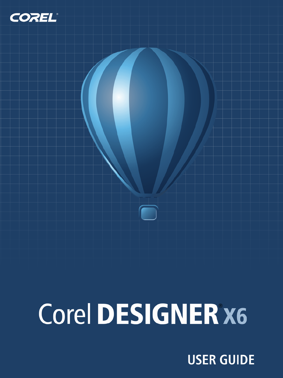
Thread and well shapes in projected mode (New!)
With the new Projected Shapes tools, you can quickly draw thread shapes, well shapes,
cylinders, and prisms in projected view, and create illustrations of bolts, nuts, and well
nuts. You can adjust the length and radius of the projected shapes, and you can specify
where to begin and end the threads and how to space them. For more information, see
“Drawing projected shapes” on page 184.
Projected shapes
Symbols (Enhanced!)
Symbols are enhanced to support object transparency and styles.
Alignment guides (New!)
With Corel DESIGNER X6, the new alignment guides help you position objects more
quickly, appearing on the fly with suggested alignment to the existing artwork on your
page. These temporary guidelines appear when you create, resize, or move objects in
relation to other objects. Alignment guides interactively connect the centers and the
edges of objects, and you can also choose to display alignment guides from the edges of
one object to the center of another object. By using the Intelligent Spacing and
Intelligent Dimensioning features, you can position, scale and rotate an object with
precision in relation to other onscreen objects.
In addition, the new Alignment and dynamic guides docker makes it easy to modify
the default settings for alignment and dynamic guides to suit your needs. For example,
if you are working with a group of objects, you can display alignment guides for
individual objects within the group, or for the bounding of the group as a whole. You
12 Corel DESIGNER X6 User Guide
can specify margins for alignment guides to help you align objects at a set distance,
and you can choose to display the alignment guides to follow the margins only, or to
follow the actual edges of the object in addition to the margins.
Using alignment guides to position objects quickly
For more information about alignment guides, see “Using alignment guides” on
page 112.
Align and Distribute docker (New!)
The new Align and distribute docker, which replaces the Align and distribute dialog
box, lets you see all available alignment options at a glance and instantly view the effect
of changes as you modify the settings. By default, objects are aligned and distributed
based on their paths. Now you can also align and distribute objects from the edge of
their outlines. You can align objects with a reference point by specifying its exact x and
y coordinates.
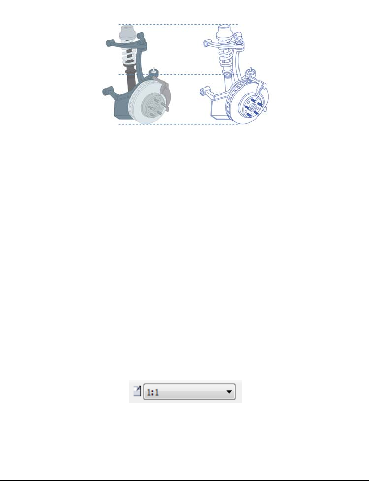
Drawing scale (New!)
You can quickly identify and change the drawing scale from the property bar when the
Pick tool is active and no objects are selected.
Drawing scale/Resolution list box
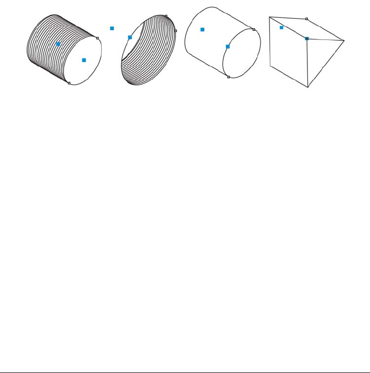
3D models at scale (New!)
You can import 3D models as 2D vector graphics at the drawing scale you want.
What’s new in Corel DESIGNER X6? 13
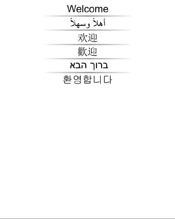
Complex script support (Enhanced!)
With Corel DESIGNER X6, the complex script support built into the overhauled text
engine ensures proper typesetting for glyphs used by Asian and Middle Eastern
languages.
Text engine improvements ensure that multilingual glyphs are displayed
correctly in your documents.
Illustrate with style and consistency
Revamped color and object styles, new color harmonies, page numbering, and
OpenType support can help you format your illustrations with consistency.
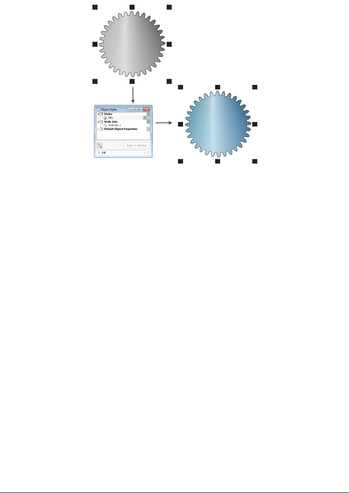
Styles engine and docker (New!)
In Corel DESIGNER X6, the revamped styles engine introduces a new Object styles
docker that simplifies the creation, application, and management of styles. A style is a
set of properties that governs the appearance of objects in your document.
Corel DESIGNER X6 also introduces style sets, which are groups of styles that make it
easier to have consistent formatting across multiple objects, produce iterative versions,
and apply formatting with speed and consistency.
14 Corel DESIGNER X6 User Guide
You can quickly change the look of an object by applying a style set.
You can create and apply styles and style sets to graphic objects, artistic and paragraph
text, callouts and dimension lines, and objects created with Linear Pattern tools. For
example, you can define an outline style by specifying attributes such as outline width,
color, and line type. For text objects, you can define a character style by specifying font
type, font style and size, text color, background color, character position, caps and more.
With style sets, you can combine multiple styles, which lets you define different
properties at the same time. For example, you could use a style set to define fill and
outline properties for callouts and dimension lines, or you could define character and
paragraph styles to set the appearance of paragraph text. This makes it faster and
easier to adjust those properties later, which is especially convenient for creating
iterative designs. You can also create child styles or child style sets that retain some but
not all of the properties in the parent style or parent style set. This is particularly useful
when working with long documents. For example, you could assign a parent character
style for headings and a child character style for subheadings.
For more information about object styles, see “Working with styles and style sets” on
page 569.
Color styles (New!)
The new Color styles docker lets you add the colors used in a document as color
styles, which makes it easier than ever before to implement a color change throughout
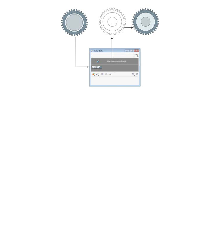
What’s new in Corel DESIGNER X6? 15
a project. To create a color style from an object, you simply drag the object onto the
Color styles docker. If you apply that color style to other objects, you can quickly
change the color and have it instantly applied to all objects linked to it.
In addition, you can break the link between an object and its color style at any time, so
that you can then edit the object independently. You can also convert color styles to
different color modes or to spot colors to prepare your document for production
printing.
Managing document colors by using the Color styles docker
Color harmonies (New!)
The new color harmony functionality lets you group a document’s color styles so that
you can quickly and easily produce iterative designs with varying color schemes. By
combining two or more color styles into a harmony, you are linking the colors into a
hue-based relationship. This lets you modify them collectively, altering the color
composition of your artwork in one step to quickly prepare a variety of alternate color
schemes. You can also edit the individual color styles in a harmony.
In addition, you can also create a special type of color harmony called a gradient,
which consists of one master color style and a number of varying shades of that color.
When you alter the master color, the gradient colors are automatically adjusted to the
same degree that the master color was altered. This is especially useful when
outputting multiple color variations of the same design.

16 Corel DESIGNER X6 User Guide
Color harmonies let you change combinations of colors easily.
Halo styles (New!)
Halos on curves can be saved as styles and applied to any curve in a project. Simply
right-click a curve with a halo, and click Object styles New style from Halo.
Page numbering (New!)
With Corel DESIGNER X6, the new Insert page number command helps you
instantly add page numbers on all pages of a document, starting on a specific page, or
starting at a particular number. This flexibility is ideal for working with multiple
Corel DESIGNER files that will eventually become a single publication.
You can choose from alphabetic and numeric formats, including roman numerals, and
you can display page numbers in lower- or upper-case lettering. In addition, page
numbers are automatically updated when you add or delete pages in your document.
You can also insert a page number inside existing artistic or paragraph text. For more
information, see “Inserting page numbers” on page 600.
Advanced OpenType support (New!)
With Corel DESIGNER X6, the reengineered text engine lets you take greater
advantage of advanced OpenType typography features, such as contextual and stylistic
alternates, fractions, ligatures, ordinals, ornaments, small caps, swashes, and more.
OpenType fonts are based on Unicode, which makes them ideal for cross-platform
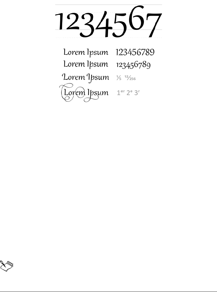
What’s new in Corel DESIGNER X6? 17
design work. In addition, the extended character sets offer outstanding language
support.
OpenType fonts let you choose alternate appearances for selected characters.
Accessible from the Property manager docker, the OpenType features let you choose
alternative appearances for individual characters, or glyphs, to suit your stylistic
preference provided that the font supports advanced OpenType. For example, you can
apply a different number, fraction, or ligature glyph to achieve a certain look for your
text. In addition, with the Interactive OpenType feature, Corel DESIGNER X6 will
suggest eligible OpenType options that you can apply to your text.
Publish to technical communication standards
Enhanced export support for CGM and SVG files makes it easier to publish you
illustrations to technical communication standards.
CGM support (Enhanced!)
When exporting CGM files, you can preserve the level of detail and use full bitmap
compression. In addition, it is easier to export to interactive WebCGM 2.x files,
preserving the attributes apsid and apsname in the XML Companion File (XCF).
The attribute apsname must be added to the objectdata.xml file. If you add
apsname in the Object data manager docker in Corel DESIGNER, only the

18 Corel DESIGNER X6 User Guide
field name is captured in the XML Companion File (XCF), not the apsname
attribute.
SVG export (Enhanced!)
SVG export can be automated, while still preserving all detail settings in the exported
files.
Increase performance, speed, and efficiency
With streamlined callout creation, improved interaction with 3D views, and enhanced
tools for selecting and editing objects, you can now be more efficient and productive.
Streamlined callout creation (New!)
You can link a callout to its source object by snapping the callout arrowhead to a snap
point. Linked callouts, also known as “sticky callouts,” are attached to the source objects
similarly to connector lines. You can specify how linked callouts move with the object.
In addition, any callout text that is based on object properties is automatically updated
when the source object property changes. You can include field names in the callout
text, and you can access the object properties of callout shapes from the Object data
manager docker.
Interactive placement of imported 3D views (New!)
When you import 3D views, you can place them and resize them interactively similarly
to other imported objects.
Freehand Pick tool (New!)
The new Freehand pick tool lets you marquee select objects by dragging around areas
of irregular shape.
Using the Freehand pick tool to select objects
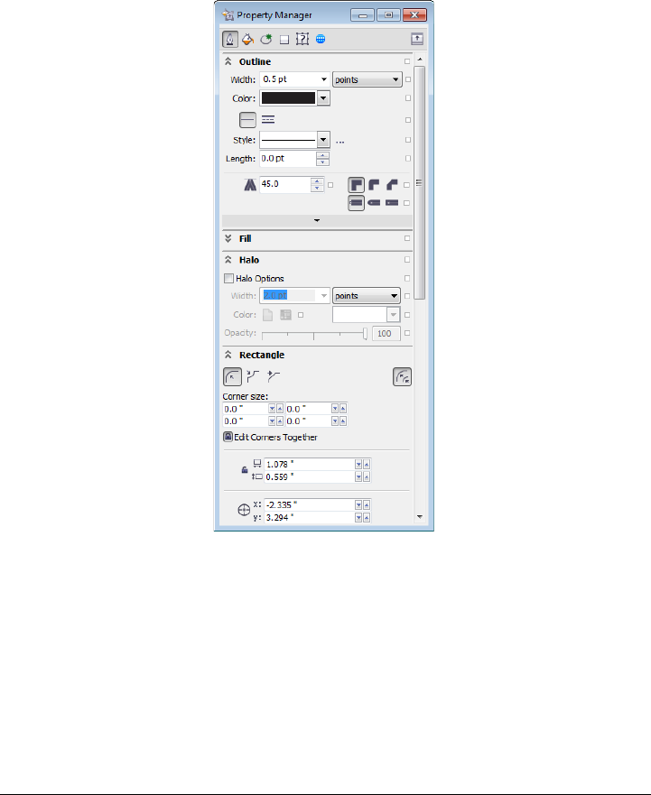
What’s new in Corel DESIGNER X6? 19
New context-sensitive Property Manager docker (New!)
In Corel DESIGNER X6, the redesigned Property manager docker now presents
only object-dependent formatting options and properties. By grouping all object
settings in one location, this time-saving docker helps you fine-tune your designs faster
than ever before.
The redesigned Property manager docker groups all object settings in one
location.
For example, if you create a rectangle, the Property manager docker automatically
presents outline, fill, and corner formatting options, as well as the rectangle’s
properties. If you create a text frame, the docker instantly displays character,
paragraph, and frame formatting options, as well as the text frame’s properties.
Multi-core processor support (New!)
Corel DESIGNER X6 has been optimized for the latest multi-core processors. The
20 Corel DESIGNER X6 User Guide
increased support lets you keep working while the suite performs resource-intensive
tasks in the background. The result is fast and responsive performance, which means
less waiting when you export files, print multiple documents, or copy and paste large
objects.
Native 64-bit support (New!)
Corel DESIGNER X6 provides support for 64-bit processors, which lets you work
faster than ever before with large files.
Master layers (New and enhanced!)
With Corel DESIGNER X6, the new and improved odd, even, and all-pages master
layers make it easier to create page-specific designs for your multi-page documents. If
you are laying out multi-page documents, such as brochures and flyers, it’s now easy to
incorporate page-specific headers, footers, and page numbers. For example, you might
want a different header design to appear on even pages than the one that appears on
odd pages.
Examples of page layouts with different odd-page and even-page master layers
Placeholder text (New!)
With Corel DESIGNER X6, the new Insert placeholder text command lets you
right-click any text frame and immediately populate it with placeholder text. This
makes it easier to assess the appearance of your document prior to finalizing its
content.
For convenience and flexibility, you can also use custom placeholder text in any
language supported by Corel DESIGNER. You simply create an RTF file containing

What’s new in Corel DESIGNER X6? 21
the text you want to use, save it to the default placeholder text folder, and
Corel DESIGNER X6 will use that text whenever you invoke the Insert placeholder
text command. For more information about creating a custom placeholder text file, see
“To insert placeholder text” on page 461.
Microsoft® Visual Basic® for Applications 7.1 (New!)
Microsoft® Visual Basic® for Applications 7.1 is available as an application for
developing custom solutions.

Learning resources 23
Learning resources
You can learn to use the product in various ways: by accessing the Help and tooltips,
by completing tutorials, and by exploring the resources on the Corel Web site
(www.corel.com). You can also check the Readme file (readme.html), which is
installed with the software.
This section contains the following topics:
• Getting help
• Using the Help and tooltips
• Welcome screen
• Macro programming guide
• Network deployment guide
• Web-based resources
• Customized training and integration resources
Getting help
Various learning resources are available. The following table can help you decide what
learning resources to consult when you need assistance. You can access more
information about some resources by clicking the corresponding links.
To S e e
Start learning the applications Online tutorials
Obtain additional information about
product tools and features
Help
Web-based resources
Welcome screen
Learn to automate tasks by using macros Macro programming guide
Find information about deploying the suite
on a network
Network deployment guide

24 Corel DESIGNER X6 User Guide
Using the Help and tooltips
The Help provides comprehensive information about product features from within the
application. If you are connected to the Internet, the application displays the Web-
based Help, which contains the latest updates. If no Internet connection is available, the
application displays the local Help, which was copied to your computer during product
installation.
You can browse through the entire list of topics, look up tools and topics in the index,
or search for specific words. You can also access the Corel® Knowledge Base™ on the
Corel Web site and other online resources from the Help window.
Tooltips provide helpful information about application controls when you position the
pointer over icons, buttons, and other user interface elements.
Documentation conventions
The following table describes important conventions used in the user guide and Help.
Find information about customized training
and workflow solutions
Customized training and integration
resources
Find specific information about the latest
version of the suite
Readme file, which is installed with the
software
Convention Description Examples
Menu Menu command A menu item and menu
command that you need to
click in sequence
Click File Open.
A note contains important
information that is relevant
to the preceding steps. It
may describe conditions
under which the procedure
can be performed.
A compound blend cannot
be copied or cloned.
If you click the Equal
margins button, you must
specify values in the To p / l e f t
margin boxes.
To S e e
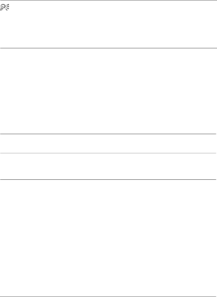
Learning resources 25
To use the Help
1Click Help Help topics.
2Click one of the following tabs:
• Contents — lets you browse through topics in the Help. To open a topic, click
the topic heading in the left pane.
• Index — lets you use the index to find a topic
• Search — lets you search the full text of the Help for a particular word or phrase
To search the Help
1Click Help Help topics.
2Click the Search tab, and type a word or phrase in the search box.
3Choose a topic from the list that appears.
If your search results do not include any relevant topics, check whether you spelled
the search word or phrase correctly. Note that the English Help uses American
spelling (for example, “color,” “favorite,” “center,” and “rasterize”), so searching for
British spellings (“colour,” “favourite,” “centre,” and “rasterise”) produces no
results.
A tip contains suggestions
for performing the preceding
steps. It may present
alternatives to the steps, or
other benefits or uses of the
procedure.
Trimming an object can
reduce the drawing file size.
You can change the number
of swatches in the color grid
by dragging the Size slider.
You can also
View context-sensitive Help from within a
dialog box
Click the Help button in the dialog box.
Print a specific Help topic Open a Help topic, click the page that you
want to print, and click Print at the top of
the Help window.
Convention Description Examples

26 Corel DESIGNER X6 User Guide
To access the user guide in PDF format
• On the Windows Start menu, click Start All Programs
CorelDRAW Technical Suite X6 Documentation Corel DESIGNER User
Guide PDF.
Welcome screen
The Welcome screen gives you easy access to application resources and lets you quickly
complete common tasks, such as opening files and starting files from templates. You can
find out about the new features in CorelDRAW Technical Suite, view technical
illustration samples on the Gallery page, and receive the latest product updates.
In addition, the following online resources are accessible from the Learning tools page
to help you get the most out of Corel DESIGNER:
• Tutorials — show you how to draw with precision, add dimension lines and
callouts, create a wiring diagram, add a 3D look to a drawing, and more
• Case studies and white papers — show you how Corel DESIGNER helps many
different industries deliver high-quality technical documentation, and help you
overcome challenges in creating technical documentation
• Tips and tricks — highlight useful tools and shortcuts, and give you a starting
point for exploring some of the CorelDRAW Technical Suite features
The Welcome screen appears when you start Corel DESIGNER. You can also access the
Welcome screen after starting the application.
To access the Welcome screen
•Click Help Welcome screen.
To view and access the available resources, click the tabs.
Macro programming guide
The CorelDRAW Technical Suite X6 Macro Programming Guide provides a streamlined
instructional approach to programming macros for CorelDRAW Technical Suite X6.
You can use either Microsoft® Visual Basic® for Applications (VBA) or Microsoft®
Visual Studio® Tools for Applications (VSTA) to create macros that automate tasks and
provide customized solutions for Corel DESIGNER, CorelDRAW®, and Corel®
PHOTO-PAINT™.

Learning resources 27
To access the macro programming guide
• On the Windows Start menu, click Start All Programs
CorelDRAW Technical Suite X6 Documentation Macro Programming
Guide PDF.
Network deployment guide
The CorelDRAW Technical Suite X6 Deployment Guide is a step-by-step resource for
deploying CorelDRAW Technical Suite X6 to a network. This guide is provided to
customers who purchase a volume (“multi-seat”) license of CorelDRAW
Technical Suite X6 for their organization. To purchase a volume license of the software
and obtain its deployment guide, please contact Corel Support Services.
Web-based resources
The following Web-based resources can help you get the most out of
CorelDRAW Technical Suite:
• Corel Knowledge Base — articles written by the Corel Technical Support Services
Team in response to questions by CorelDRAW Technical Suite users
• CorelDRAW.com community — an online environment to share your experience
with the product, ask questions, and receive help and suggestions from other users
• Learning resources — a Web page that contains links to online tutorials, case
studies, and more
An active Internet connection is required to access Web-based resources.
Customized training and integration resources
Corel Corporation has training partnerships with other firms.
Corel customized training
Corel Training Specialists can provide you with customized training, tailored to your
work environment, to help you get the most out of the Corel software that you’ve
installed. These experts will help you develop a curriculum that is practical and
relevant to the needs of your organization. For more information, please visit
www.corel.com/customizedtraining.

28 Corel DESIGNER X6 User Guide
Corel Training Partners
A Corel® Training Partner (CTP) is an independent, officially accredited local
organization that provides training and training resources for Corel products. CTPs are
located worldwide for your convenience. Please visit www.corel.com/
trainingpartners to find a partner near you.
Corel Technology Partners
Corel Technology Partners are businesses that embed Corel technology in their
products, develop plug-in applications for Corel software, or integrate standalone
applications into Corel technology solutions. This comprehensive program is designed
especially for developers and consultants. It includes the components that are necessary
to design, develop, test, and market custom solutions related to Corel products.
For more information about Corel Technology Partners, please email Corel Corporation
at techpartner@corel.com.

Corel DESIGNER workspace tour 29
Corel DESIGNER workspace tour
Becoming familiar with the terminology and workspace of Corel DESIGNER will help
you easily follow this user guide’s concepts and procedures.
This section contains the following topics:
• Corel DESIGNER terms and concepts
• Corel DESIGNER application window
• Corel DESIGNER workspace tools
Corel DESIGNER terms and concepts
Before you get started with Corel DESIGNER, you should be familiar with the
following terms.
Term Description
object An element in a drawing, such as an image, shape, line, text,
curve, or symbol
drawing The work you create in Corel DESIGNER: for example,
technical drawings, schematics, and diagrams
vector graphic An image generated from mathematical descriptions that
determine the position, length, and direction in which lines are
drawn
bitmap An image composed of grids of pixels or dots
artistic text A type of text to which you can apply special effects, such as
shadows
paragraph text A type of text to which you can apply formatting options, and
which can be edited in large blocks
30 Corel DESIGNER X6 User Guide
Corel DESIGNER application window
When you launch Corel DESIGNER, the application window opens, containing a
drawing window. The rectangle in the center of the drawing window is the drawing
page where you create your drawing. Although more than one drawing window can be
opened, you can apply commands to the active drawing window only.
The Corel DESIGNER application window appears below. A description of its parts
follows.
Part Description
Menu bar The area containing pull-down menu options
Property bar A detachable bar that contains properties of the active tool or
object. For example, when the text tool is active, the text
property bar displays commands that create and edit text.
Toolbar A detachable bar that contains shortcuts to menu and other
commands
Title bar
Menu bar
Toolbox
Ruler
Drawing
window
Drawing
page
Document
navigator Status bar Navigator
Docker
Property
bar
Toolbar
Color
palette
Document
palette

Corel DESIGNER workspace tour 31
To toggle between displaying and hiding the status bar, click View To o l b a r s
Status bar.
For information about displaying and hiding the rulers, see “To hide or display
the rulers” on page 603.
Corel DESIGNER workspace tools
Application commands are accessible through the menu bar, toolbars, toolbox, property
bar, and dockers. The property bar and dockers provide access to commands that relate
Title bar The area displaying the title of the currently open drawing
Rulers Horizontal and vertical borders that are used to determine the
size and position of objects in a drawing
Toolbox A floating bar with tools for creating and modifying objects in
the drawing
Drawing window The area outside the drawing page bordered by the scroll bars
and application controls
Drawing page The rectangular area inside the drawing window. It is the
printable area of your work area.
Docker A window containing available commands and settings relevant
to a specific tool or task
Color palette A dockable bar that contains color swatches
Document palette A color palette that helps you keep track of the colors that you
use in your document and store them for future use.
Status bar An area at the bottom of the application window that contains
information about object properties such as type, size, and
resolution. The status bar also shows the current mouse
position.
Document navigator The area at the bottom left of the drawing window that
contains controls for moving between pages and adding pages
Navigator A button at the lower-right corner of the drawing window that
opens a smaller display to help you move around a drawing
Part Description
32 Corel DESIGNER X6 User Guide
to the active tool or current task. The property bar, dockers, toolbars, and toolbox can
be opened, closed, and moved around your screen at any time.
You can customize many of these workspace elements to suit your needs. For more
information, see “Customizing Corel DESIGNER” on page 855.
Standard toolbar
The standard toolbar contains buttons that are shortcuts to many of the menu
commands.
The standard toolbar is displayed by default. For information about customizing the
position, contents, and appearance of toolbars, see “Customizing toolbars” on page 863.
Click this button To
Start a new drawing
Open a drawing
Save a drawing
Print a drawing
Cut selected objects to the Clipboard
Copy selected objects to the Clipboard
Paste the Clipboard contents into a drawing
Undo an action
Restore an action that was undone
Display the Connect docker and search for content such as
clipart, photos, fonts, and more
Corel DESIGNER workspace tour 33
More about toolbars
In addition to the standard toolbar, Corel DESIGNER has toolbars for specific kinds of
tasks. For example, the Te x t toolbar contains commands relevant to using the Te x t tool.
If you use a toolbar frequently, you can display it in the workspace at all times.
The table below describes toolbars other than the standard toolbar.
Import a drawing
Export a drawing
Set a zoom level
Start Corel applications
Open the Welcome screen
Enable or disable automatic alignment for the grid, guidelines,
objects, and dynamic guides
Open the Options dialog box
Toolbar Description
Text Contains commands for formatting and aligning text
Zoom Contains commands for zooming in and out of a drawing page
Internet Contains commands for Web-related tools for creating rollovers
and publishing to the Internet
Print Merge Contains commands for print merge items that combine text
with a drawing, such as creating and loading data files, using
data fields for variable text, and inserting print merge fields
Transform Contains commands for skewing, rotating, and mirroring
objects
Click this button To
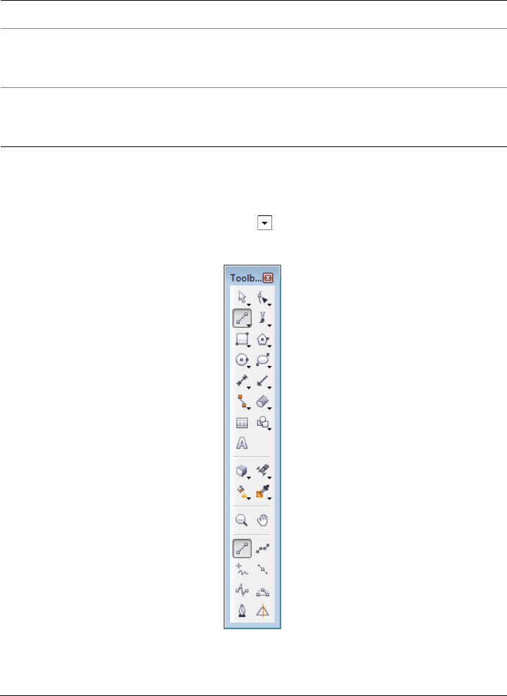
34 Corel DESIGNER X6 User Guide
Exploring the toolbox
The Corel DESIGNER toolbox shows the active tool and the available categories of
tools in the upper area. The options symbol indicates that there are additional tools
or options.
Macros Contains commands for editing, testing, and running macros
Layout Contains commands related to the layout of your document,
including PowerClip frames, text frames, columns, and
alignment guides.
Drawing plane Contains commands for choosing a drawing plane and a
drawing profile, and lets you access the Projected axes docker.
This toolbar is displayed by default.
Toolbar Description
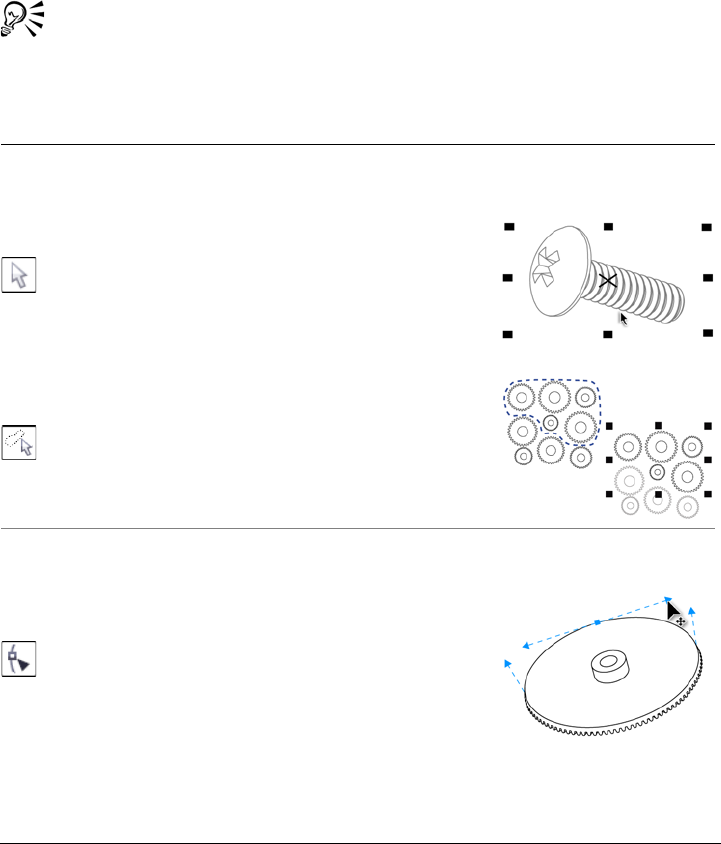
Corel DESIGNER workspace tour 35
When you choose a tool, any additional tools or options appear in the options area at
the bottom of the toolbox. When you choose a tool in the options area, it becomes the
active tool.
For example, if you click the Curve tools button in the upper area, you see its associated
tools in the options area. If you click the 2-point line tool in the options area, it
becomes the active tool, and its icon appears on the Curve tools button in the upper
area.
You can use flyout menus instead of the options area. Click To o l s Options,
click To o l b o x in the Wor ksp ac e list of categories, and enable Display tool
groups as flyout menus.
The following table provides descriptions of the tools in the Corel DESIGNER toolbox.
Pick tools
The Pick tool lets you select, size, skew, and rotate
objects.
The Freehand pick tool lets you select objects by using
a freehand selection marquee.
Shape tools
The Shape tool lets you edit a curve object or text
character by manipulating nodes.
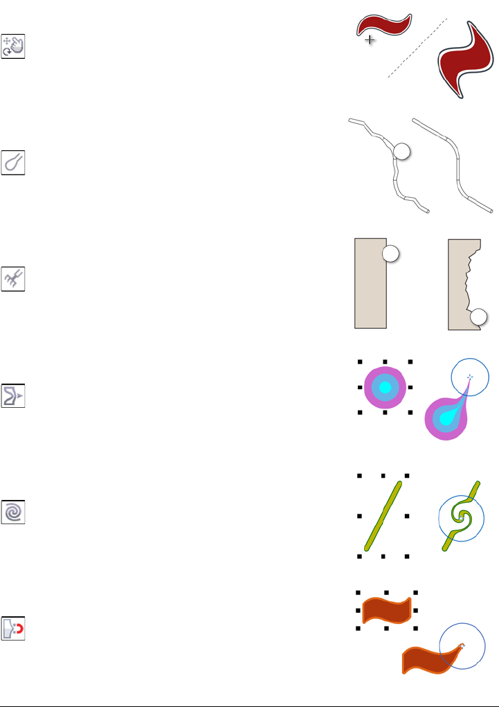
36 Corel DESIGNER X6 User Guide
The Free transform tool lets you transform an object by
using the Free rotation, Free angle reflection, Free
scale, and Free skew controls on the property bar.
The Smudge brush tool lets you distort a vector object
by dragging along its outline.
The Roughen brush tool lets you distort the edge of a
vector object by dragging along its outline.
The Smear tool lets you shape an object by pulling
extensions or making indents along its outline.
The Tw i r l tool lets you create swirl effects by dragging
along the edge of objects.
The Attract tool lets you shape objects by attracting
nodes to the cursor.
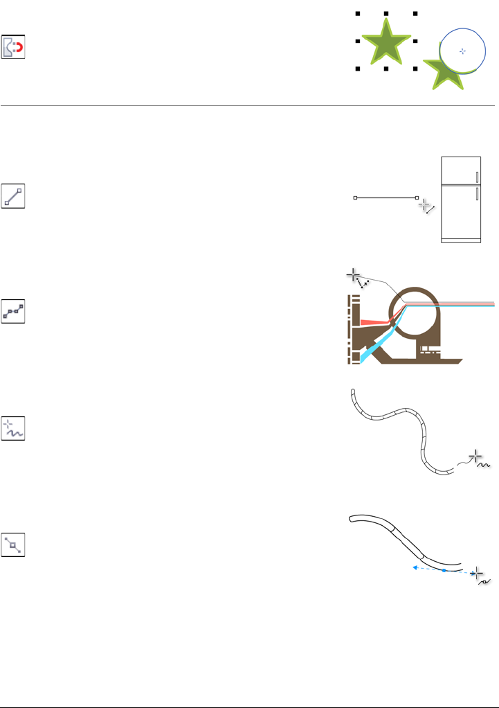
Corel DESIGNER workspace tour 37
The Repel tool lets you shape objects by pushing nodes
away from the cursor.
Curve tools
The 2-point line tool lets you draw a straight two-point
line segment.
The Multi-point line tool lets you draw lines and curves
one segment at a time, in preview mode.
The Freehand tool lets you draw single line segments
and curves.
The Bézier curve tool lets you draw curves one segment
at a time.
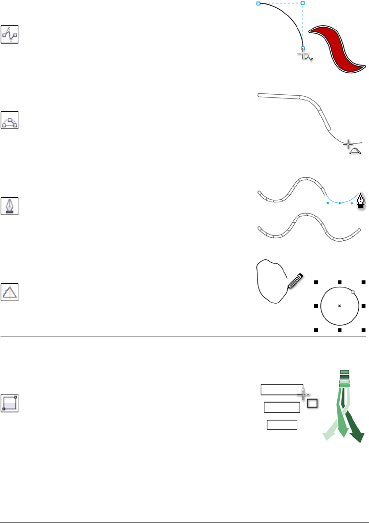
38 Corel DESIGNER X6 User Guide
The B-spline tool lets you draw curved lines by setting
control points that shape the curve without breaking it
into segments.
The 3-point curve tool lets you draw a curve by
defining the starting point, endpoint, and center point.
The Pen tool lets you draw curves in segments and
preview each segment as you draw.
The Smart drawing tool converts your freehand strokes
to basic shapes and smoothed curves.
Rectangle tools
The 2-point rectangle tool lets you draw a rectangle by
dragging diagonally.
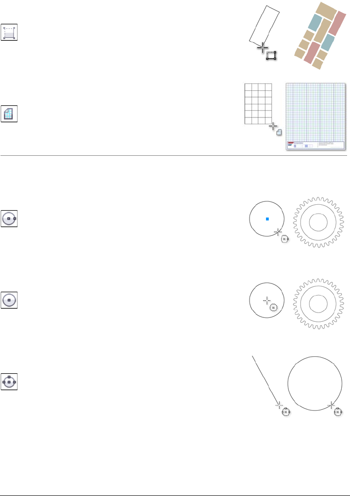
Corel DESIGNER workspace tour 39
The 3-point rectangle tool lets you draw rectangles at
an angle.
The Graph paper tool lets you draw a grid to simulate
graph paper.
Circle tools
The Center-point circle tool lets you draw a circle by
specifying the center point and a point on the
circumference.
The Center-radius circle tool lets you draw a circle by
specifying a value for the radius and then clicking where
you want the center to be.
The 3-point circle tool lets you draw a circle by
specifying three points on the circumference.
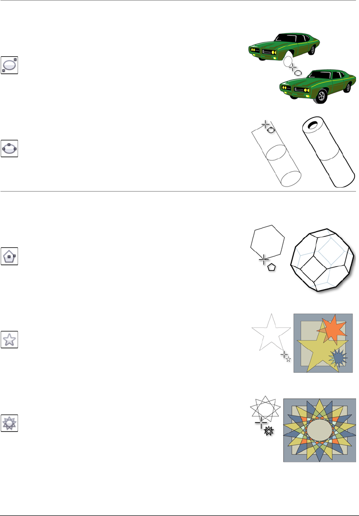
40 Corel DESIGNER X6 User Guide
Ellipse tools
The 2-point ellipse tool lets you draw an ellipse by
dragging diagonally.
The 3-point ellipse tool lets you draw ellipses at an
angle.
Center-point polygon tools
The Center-point polygon tool lets you draw a polygon
by dragging from the center to a point (vertex) on the
polygon.
The Star tool lets you draw perfect stars.
The Complex star tool lets you draw complex stars that
have intersecting sides.
Corel DESIGNER workspace tour 41
Text tool
The Te x t tool lets you add text, create a paragraph text
frame and type within it, or type text along a path if a
curve is selected.
Dimension tools
The Parallel dimension tool lets you draw slanted
dimension lines.
The Horizontal or vertical dimension tool lets you
draw horizontal or vertical dimension lines.
The Angular dimension tool lets you draw angular
dimension lines.
The Segment dimension tool lets you display the
distance between end nodes in single or multiple
segments.
42 Corel DESIGNER X6 User Guide
The Radial dimension tool lets you display the radius of
a circle or circular arc.
The Diametric dimension tool lets you display the
diameter of a circle or a circular arc.
Callout tools
The 1-leg callout tool lets you draw a callout with one
leading line.
The 2-leg callout tool lets you draw a callout with a
two-segment leading line.
The 3-leg callout tool lets you draw a callout with a
three-segment leading line.
Corel DESIGNER workspace tour 43
The Te x t s o u r c e button lets you enter callout text
interactively, from the Clipboard, from object properties,
or incrementally.
Connector tools
The Straight-line connector tool lets you draw a
straight connector line.
The Right-angle connector tool lets you draw a right-
angle connector line.
The Right-angle round connector tool lets you draw a
right-angle connector line with curved corners.
The B-spline connector tool lets you draw a curved
connector line by using control points.
44 Corel DESIGNER X6 User Guide
The Bézier curve connector tool lets you draw a
curved connector line one segment at a time.
The Edit anchor tool lets you modify connector line
anchor points.
Projected Shapes tools
The Thread tool lets you draw threaded shapes in
projected view.
The Well tool lets you draw threaded well shapes in
projected view.
The Cylinder tool lets you draw cylinders in projected
view.
Corel DESIGNER workspace tour 45
The Prism tool lets you draw prism shapes in projected
view.
Table tool
The Ta b l e tool lets you draw and edit tables.
Perfect Shapes™ tools
The Basic shapes tool lets you choose from a full set of
shapes, including a hexagram, a smiley, and a right-angle
triangle.
The Arrow shapes tool lets you draw arrows while
choosing the shape, direction, and number of heads.
The Flowchart shapes tool lets you draw flowchart
symbols. These controls are available on the property
bar.
46 Corel DESIGNER X6 User Guide
The Miscellaneous shapes tool lets you draw ribbon
objects and explosion shapes. These controls are available
on the property bar.
The Callout shapes tool lets you draw callouts and
labels. These controls are available on the property bar.
Linear pattern tools
The Linear pattern brush tool lets you apply brush
strokes to a curve and create sweep arrows and similar
objects.
The Linear pattern sprayer tool lets you draw chains,
hoses, pipes, and similar objects.
The Linear pattern preset tool lets you draw curves by
using preset strokes.
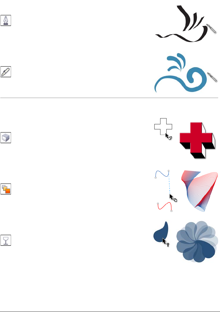
Corel DESIGNER workspace tour 47
The Calligraphic tool lets you draw lines that vary in
thickness according to the direction of the line and the
angle of the pen nib.
The Pressure tool lets you draw lines that vary in
thickness according to the pressure of the pen nib.
Interactive tools
The Extrude tool lets you apply 3D effects to objects to
create the illusion of depth.
The Blend tool lets you transform one object into
another through a series of intermediate shapes and
colors.
The Transparency tool lets you apply a transparency to
an object to partially reveal image areas underneath.
48 Corel DESIGNER X6 User Guide
The Envelope tool lets you distort the shape of an object
by applying an envelope to it and dragging the nodes of
the envelope.
The Drop shadow tool lets you create the illusion of
lighting in a two-dimensional drawing by adding a
shadow to an object. You can adjust properties such as
feathering, opacity, edge style, and color.
The Contour tool lets you create a series of concentric
shapes that radiate into or out of an object.
The Distort tool lets you transform objects by applying
Push and Pull, Zipper, or Twister effects.
Deletion tools
The Virtual segment delete tool lets you delete
portions of objects between intersecting lines.
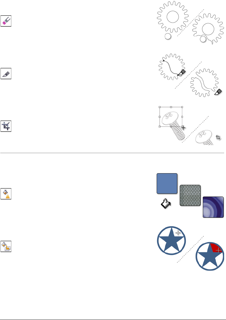
Corel DESIGNER workspace tour 49
The Eraser tool lets you remove unwanted areas in a
drawing.
The Knife tool lets you slice an object into two separate
objects.
The Crop tool lets you remove the areas outside a
selection.
Interactive fill tools
The Fountain fill tool lets you fill an object with a
gradient of colors or shades.
The Smart fill tool lets you create objects from enclosed
areas and then apply a fill to those objects.
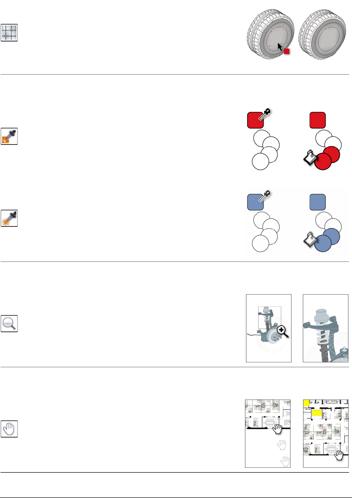
50 Corel DESIGNER X6 User Guide
The Mesh fill tool lets you fill an object by blending
multiple colors or shades arranged over a mesh grid.
Eyedropper tools
The Color eyedropper tool lets you sample a color from
an object in the drawing window or on the desktop and
apply it to other objects.
The Attributes eyedropper tool lets you copy object
properties, such as line thickness, size, and effects, from
an object in the drawing window and apply them to
other objects.
Zoom tool
The Zoom tool lets you change the magnification level
in the drawing window.
Pan tool
The Pan tool lets you drag hidden areas of a drawing
into view without changing the zoom level.
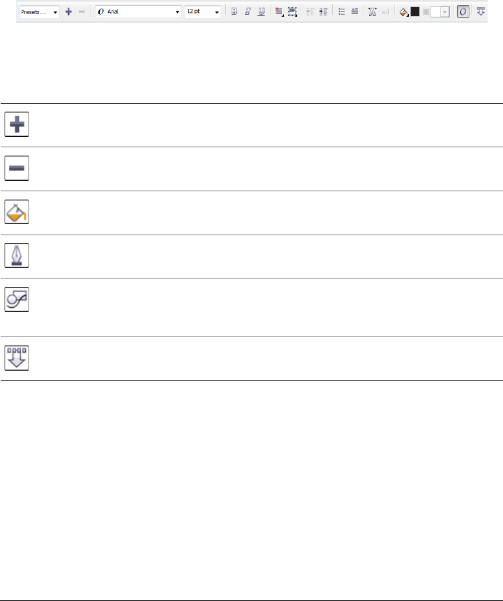
Corel DESIGNER workspace tour 51
Property bar
The property bar displays the most commonly used functions that are relevant to the
active tool or to the task you’re performing. The property bar content changes
depending on the tool or task. For example, when you click the Te x t tool in the toolbox,
the property bar displays only text-related commands, such as text, formatting,
alignment, and editing tools.
You can customize the contents and position of the property bar to suit your needs. For
more information, see “Customizing the property bar” on page 867.
Common property bar buttons
Dockers
Dockers display the same type of controls as a dialog box, such as command buttons,
options, and list boxes. Unlike most dialog boxes, you can keep dockers open while
working on a document, so you can readily access the commands to experiment with
different effects.
An example is the Property manager docker. When this docker is open, you can click
an object in the drawing window and view formatting, dimensions, and other properties
of the object.
The Add preset button lets you save the current settings for
reuse.
The Delete preset button lets you delete the item selected in
the Preset list box.
The Fill button lets you open a dialog box where you set up a
fill to apply to an object.
The Outline pen button opens a dialog box where you set line
properties.
The Geometric properties button opens the Property
manager docker and lets you set coordinates for the selected
object.
The Keep settings button lets you use the current settings as
the defaults for new objects.
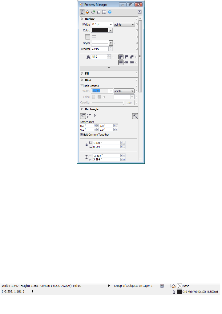
52 Corel DESIGNER X6 User Guide
Dockers can be either docked or floating. Docking a docker attaches it to the edge of
the application window. Undocking a docker detaches it from other parts of the
workspace, so it can be easily moved around. You can also collapse dockers to save screen
space.
Status bar
The status bar displays information about selected objects, such as width and height,
cursor position, and relevant commands. While you are drawing a non-freehand line or
curve, the segment length and total length for all segments are displayed. It also
displays document color information, such as the document color profile and color
proofing status.
See “Customizing the status bar” on page 869 for information about customizing the
contents and appearance of the status bar.
The graphic shows some of the information displayed in a status bar.

Corel DESIGNER basics 53
Corel DESIGNER basics
Corel DESIGNER lets you create and edit drawings. In this section, you can find
information about commonly performed tasks.
This section contains the following topics:
• Understanding vector graphics and bitmaps
• Starting and opening drawings
• Acquiring images from scanners and digital cameras
• Undoing, redoing, and repeating actions
• Zooming, panning, and scrolling
• Previewing drawings
• Choosing viewing modes
•Working with views
• Saving drawings
• Backing up and recovering files
• Adding and accessing drawing information
• Closing drawings and quitting Corel DESIGNER
Understanding vector graphics and bitmaps
The two main types of computer graphics are vector graphics and bitmaps. Vector
graphics are made of lines and curves, and they are generated from mathematical
descriptions that determine the position, length, and direction in which lines are drawn.
Bitmaps, also known as raster images, are composed of small squares called pixels; each
pixel is mapped to a location in an image and has numerical color values.
Vector graphics are ideal for logos and illustrations because they are resolution-
independent and can be scaled to any size, or printed and displayed at any resolution,
without losing detail and quality. In addition, you can produce sharp and crisp outlines
with vector graphics.
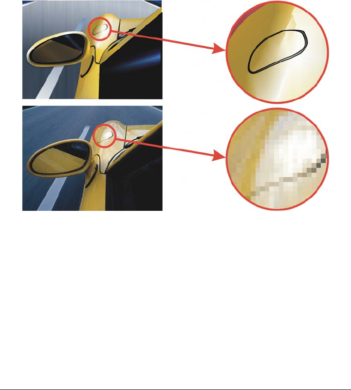
54 Corel DESIGNER X6 User Guide
Bitmaps are excellent for photographs and digital paintings because they reproduce
color gradations well. Bitmaps are resolution-dependent — that is, they represent a
fixed number of pixels. They look good at their actual size, but they can appear jagged
or lose image quality when scaled, or when displayed or printed at a resolution higher
than their original resolution.
You can create vector graphics in Corel DESIGNER. You can also import bitmaps (such
as JPEG and TIFF files) into Corel DESIGNER and add them to your drawings. For
information about working with bitmaps, see “Working with bitmaps” on page 633.
Top: A vector graphic consists of lines and fills. Bottom: A bitmap is made up
of pixels.
Starting and opening drawings
When you start Corel DESIGNER, you can choose the workspace with which you feel
the most comfortable. For example, you can choose a workspace that has the look and
feel of CorelDRAW. If you are new to Corel DESIGNER, it is best to choose the default
workspace, on which all procedures in the Help and user guide are based.
Corel DESIGNER lets you start a new drawing from a blank page, a template, or an
existing drawing. A blank page gives you the freedom to specify every aspect of a
drawing. A template provides you with a starting point and leaves the amount of

Corel DESIGNER basics 55
customization up to you. The templates included with the application are available
under the following categories:
•ANSI (American National Standards Institute)
•Architectural
•DIN (Deutsches Institut für Normung)
•Engineering
•ISO (International Organization for Standardization®)
For information about starting a drawing from a template, see “To start a document
from a template” on page 564. For more information about creating and using
templates, see “Working with templates” on page 561.
Notes for starting new drawings
When starting a new drawing, Corel DESIGNER lets you specify page, document, and
color management settings. You can choose from a list of preset settings, which are
based on how you intend to use the drawing. For example, you can choose the Web
option if you are creating a drawing for the Internet, or the Default CMYK option if
you are creating a document destined for commercial printing. However, if the preset
settings are not suitable for the drawing that you want to create, you can also customize
the settings and save them for future use.
Notes for opening existing drawings
Basing a new drawing on an existing drawing lets you reuse objects and page settings.
Corel DESIGNER lets you open existing drawings saved to the Corel DESIGNER (DSF
or DES) format as well as drawings and projects saved to various other file formats, such
as CorelDRAW (CDR), Adobe® Illustrator® (AI), Adobe Portable Document Format
(PDF), Encapsulated PostScript® (EPS), and Computer Graphics Metafile (CGM).
However, you may not be able to open certain files, depending on their file type and
contents. In such cases, you can try importing the files as objects in an open drawing.
For information about the file formats that you can import into Corel DESIGNER, see
“Supported file formats” on page 783.
If the drawing you are opening is from an earlier version of Corel DESIGNER and
contains text in a language different from the language of your operating system, you
can choose code page settings to ensure that text is properly converted according to the
Unicode® Standard. Code page settings help you correctly display text such as
keywords, file names, and text entries outside the drawing window — for example, in
the Object manager and Object data manager dockers. To display text correctly in

56 Corel DESIGNER X6 User Guide
the drawing window, you must use encoding settings. For more information, see
“Displaying text correctly in any language” on page 526.
If the drawing you are opening contains an embedded International Color
Consortium® (ICC) profile, the embedded color profile remains the document’s color
profile. For more information, see “Understanding color management” on page 385.
If you are using Windows 7 or Windows 8, you can search for drawings by different
criteria, such as filename, title, subject, author, keyword, comment, text within the file,
and other properties attached to the file. For more information about searching for files
with Windows 7 or Windows 8, see the Windows Help. If your operating system is
Windows XP, you can use Windows Desktop Search to find files. For more information
about browsing and searching for content, see “Browsing and searching for content” on
page 88.
You can also display previous versions of a drawing.
To start Corel DESIGNER
1Click Start All programs CorelDRAW Technical Suite X6
Corel DESIGNER X6.
2In the Select workspace dialog box, choose a workspace from the list box.
If you do not want the Select workspace dialog box to appear each time you start
Corel DESIGNER, enable the Do not show this dialog box on startup check
box.
Procedures in the Help are based on the default workspace.
To restore the Select workspace dialog box, click To o l s Customization,
click Wo rk s pa ce, and enable the Select workspace at startup check box.
To start a drawing
1Do one of the following:
• On the Welcome screen, click Quick start New blank document.
• In the application window, click File New.
2Type a filename in the Name text box.
3From the Preset destination list box, choose an output destination for the
drawing:

Corel DESIGNER basics 57
• Corel DESIGNER default — applies the Corel DESIGNER default settings for
creating graphics that are destined for printing
• Default CMYK — applies settings for creating graphics that are destined for
commercial printing
• Default RGB — applies settings for creating graphics that are destined for
printing to a high-fidelity printer
• Web — applies settings for creating graphics that are destined for the Internet
• Custom — lets you customize destination settings for a document
You can also
Change the unit of measurement for the
page
Choose a unit of measurement from the
Drawing units list box.
Change the page size Choose a page size for the drawing from the
Size list box or type values in the Width and
Height boxes.
Change the page orientation Click one of the following page orientation
buttons:
•Portrait
•Landscape
Set the number of pages Type a value in the Number of pages box.
Set the default color mode for the document
to RGB or CMYK
Choose a color mode from the Primary
color mode list box.
Set the resolution for effects that will likely
be rasterized, such as transparency, drop
shadow, and bevel effects
Choose a rendering resolution from the
Rendering resolution list box.
Choose the preview mode for the drawing Choose a preview mode from the Preview
mode list box.
Choose an RGB profile for the drawing Choose a default RGB profile from the RGB
profile list box.
Choose a CMYK profile for the drawing Choose a default CMYK profile from the
CMYK profile list box.
Choose a Grayscale profile for the drawing Choose a default Grayscale profile from the
Grayscale profile list box.
58 Corel DESIGNER X6 User Guide
When you choose a color mode from the Primary color mode list box, it
becomes the default color mode for the document. The default color mode
affects how colors work together in effects such as blends and transparencies.
It does not restrict the type of colors that you can apply to a drawing. For
example, if you set the color mode to RGB, you can still apply colors from a
CMYK color palette to the document.
The primary color mode also specifies the default color mode for exporting
documents. For example, if you choose the RGB color mode and export a
document as a JPEG, the color mode is automatically set to RGB.
The settings that are displayed in the Color settings area of the Create a new
document dialog box are based on the settings that are specified in the
Default color management settings dialog box.
If you do not want to show the Create a new document dialog box and prefer
to use the default settings to create new documents, enable the Do not show
this dialog again check box.
You can restore the Create a new document dialog box when starting
drawings by clicking To o l s Options, clicking General in the Wo rksp ace
list of categories, and enabling the Show new document dialog box check
box.
To create a custom preset
1In the application window, click File New.
2In the Create a new document dialog box, choose the settings that you want to
save as a preset destination.
3Click the Add preset button.
4In the Add preset dialog box, type a name for the new destination preset.
Choose a default method for out-of-gamut
colors to be mapped into gamut
Choose an option from the Rendering
intent list box.
You can also

Corel DESIGNER basics 59
You can delete a destination preset by choosing the preset name from the
Preset destination list box and clicking the Remove preset button.
To open a drawing
1Click File Open.
2Locate the folder where the drawing is stored.
3Click a filename.
4Click Open.
You can also
Extract an embedded International Color
Consortium (ICC) profile to the color folder
in which the application is installed
Enable the Extract embedded ICC profile
check box.
This option is not available for all file
formats.
Maintain layers and pages when you open
files
Enable the Maintain layers and pages
check box.
If you disable the check box, all layers are
combined in a single layer.
This option is not available for all file
formats.
View thumbnail of a drawing (Windows 7 and Windows 8) Click the
arrow button next to the Views button, and
click Extra large icons, Large icons,
Medium icons, or Small icons.
(Windows XP) Do one of the following:
•Enable the Preview check box.
•Click the View menu button, and select
Thumbnails.

60 Corel DESIGNER X6 User Guide
To open a file you have recently worked on, click File Open recent, and click
the filename.
If you have multiple files open, you can navigate between them by clicking
Window Document, and then clicking the name of the file that you want
to display in the drawing window.
Acquiring images from scanners and digital cameras
You can load photos from digital cameras and scan images in Corel DESIGNER.
Corel DESIGNER supports scanners that use Microsoft Windows Image Acquisition
(WIA), which provides a standard interface for loading images. If your scanner does not
support WIA, you can use the TWAIN driver of your scanner for loading images.
TWAIN is supported by both the 32-bit and 64-bit versions of Corel DESIGNER The
Choose a code page (Windows 7 and Windows 8) Choose a code
page from the Select code page list box.
This option is not available for all file
formats.
(Windows XP) Choose a code page from the
Code page list box.
Search for a drawing (Windows 7 and
Windows 8)
Type a word or phrase in the search box.
The search box looks for files only in the
current folder and subfolders. To search for a
drawing in another location, you must first
navigate to the folder where the drawing is
stored.
Access a previous version of a file (Windows
7 and Windows 8)
Right-click a file, and click Restore
previous versions.
You can access a previous version of a file
only if System Protection is turned on.
For detailed information about accessing
previous versions of files, see the Windows
Help.
You can also

Corel DESIGNER basics 61
software interfaces and options vary. For information about using the software
associated with your scanner or digital camera, see the manufacturer’s documentation.
To load photos from a digital camera
1Connect a digital camera to your computer.
2Click File Acquire image Select TWAIN source
3Choose a digital camera from the Sources box.
4Click File Acquire image Acquire.
5Choose the images that you want to load from the dialog box that appears.
You are presented with the digital camera’s TWAIN driver interface for loading
images. Options vary, depending on the digital camera.
6Click Get pictures.
On your digital camera’s interface, this button may have a different name.
To load additional photos during the same session, click File Acquire image
Acquire.
If your digital camera does not have a TWAIN driver, you can still open photos
in Corel DESIGNER by clicking File Import, browsing to the digital
camera directory, and selecting the photos that you want to open.
To scan images
1Click File Acquire image, and click one of the following commands:
• Select WIA source — for a scanner that uses a WIA driver (available only on
Windows XP and later versions)
• Select TWAIN source— for a scanner that uses a TWAIN driver
A command appears disabled if a compatible WIA or TWAIN scanner driver is not
installed.
2Choose a scanner from the dialog box that appears.
3Click Select.
4Click File Acquire image Acquire.
5Preview the image, and select the area that you want to scan.
WIA, in combination with some scanners, supports scanning of multiple areas to
separate files.
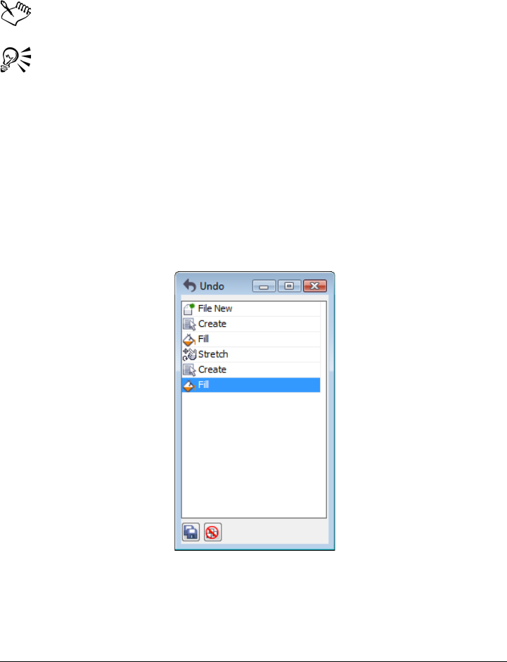
62 Corel DESIGNER X6 User Guide
6Click Scan.
On your scanner’s interface, this button may have a different name, such as OK or
Send.
The WIA interface is available only for the Windows XP and later versions.
To scan additional images during the same session, click File Acquire image
Acquire.
Undoing, redoing, and repeating actions
You can undo the actions that you perform in a drawing, starting with the most recent
action. If you don’t like the result of undoing an action, you can redo it. Reverting to
the last saved version of a drawing also lets you remove one or more actions. Certain
actions applied to objects, such as stretching, filling, moving, and rotating, can be
repeated to create a stronger visual effect.
Undo docker
Customizing the Undo settings lets you increase or decrease the number of actions that
you can undo or redo.
Corel DESIGNER basics 63
To undo, redo, and repeat actions
When you undo a series of actions in the Undo docker, all actions listed below
the action that you click are undone.
When you redo a series of actions in the Undo docker, the action that you click
and all preceding undone actions are redone.
You can repeat an action on another object or group of objects by selecting the
object or objects and clicking Edit Repeat.
You can also undo or redo a series of actions by clicking the arrow button next
to the Undo button or Redo button on the Standard toolbar and
choosing an action from the list.
To specify the Undo settings
1Click To o l s Options.
2In the Wo rk s pa ce list of categories, click General.
3In the Undo levels area, type a value in one or both of the following boxes:
• Regular — specifies the number of actions that can be reversed when you use
the Undo command with vector objects
• Bitmap effects — specifies the number of actions that can be reversed when you
work with bitmap effects
To Do the following
Undo an action Click Edit Undo.
Redo an action Click Edit Redo.
Undo or redo a series of actions Click Window Undo manager. In the
Undo docker, click the action that precedes
all the actions that you want to undo, or
click the last undone action that you want to
redo.
Revert to the last saved version of a drawing Click File Revert.
Repeat an action Click Edit Repeat.

64 Corel DESIGNER X6 User Guide
The value that you specify is limited only by your computer’s memory
resources. The higher the value you specify, the greater the demand on memory
resources.
Zooming, panning, and scrolling
You can change the view of a drawing by zooming in to get a closer look or by zooming
out to see more of the drawing. You can experiment with a variety of zoom options to
determine the amount of detail you want.
Panning and scrolling are two additional ways to view specific areas of a drawing. When
you work at high magnification levels or with large drawings, you may not be able to
see the whole drawing. Panning and scrolling let you move the page around in the
drawing window to view previously hidden areas.
You can zoom in and out while you are panning, and you can pan while you are
zooming. In this way, you can avoid having to alternate between the two tools.
You can also use the Quick Pan mode to switch from any active tool to the Pan tool.
This feature lets you pan without having to change tools.
If you use a mouse wheel, the wheel zooms in and zooms out by default. You can also
use the mouse wheel to scroll.
You can specify default zooming and panning settings.
To zoom
1In the toolbox, click the Zoom tool .
2On the property bar, click one of the following:
• Zoom in
• Zoom out
• Zoom to selected
• Zoom to all objects
• Zoom to page
• Zoom to page width
• Zoom to page height
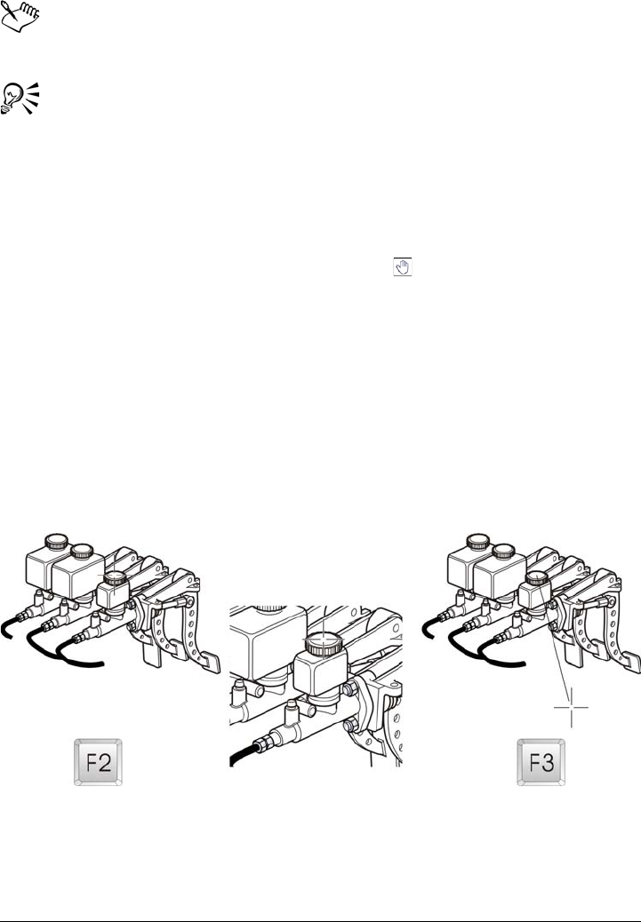
Corel DESIGNER basics 65
The Zoom to selected button is available only if one or more objects are
selected before you click the Zoom tool.
When you are not editing text, you can also access the Zoom tool by pressing
the Z key.
Using the Zoom tool, you can also zoom in by clicking anywhere in the
drawing window or dragging to select a specific area to magnify. To zoom out,
right-click in the drawing window, or drag with the right mouse button to
select a specific area.
You can also zoom in by using the Pan tool and double-clicking in the
drawing window. To zoom out, right-click in the drawing window.
Use the following keyboard shortcuts to zoom during any task, such as when
you are drawing an object:
•F2 — zoom in around the pointer
•F3 — zoom out around the pointer
•F4 — zoom to all objects
•F5 — refresh the drawing window
•F6 — zoom to selected objects
•F7 — zoom to the page
The F2 and F3 shortcut keys let you zoom in and out around the pointer.
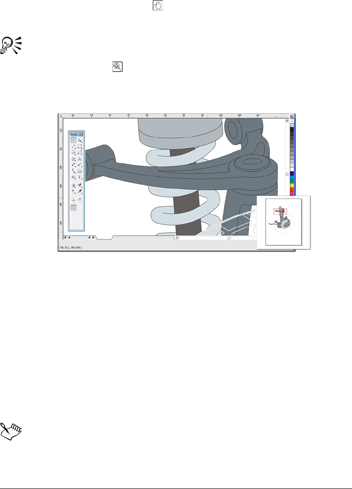
66 Corel DESIGNER X6 User Guide
To pan in the drawing window
1In the toolbox, click the Pan tool .
2Drag in the drawing window until the area you want to view appears.
To pan in the drawing window while zoomed in on the drawing, click the
Navigator button in the lower-right corner of the drawing window.
You can quickly center the page in the drawing window by double-clicking the
Pan tool in the toolbox.
Using the Navigator (lower-right), you can display any part of a drawing
without having to zoom out.
To switch to the Quick Pan mode
1Click any selection, drawing, or shaping tool, and start using it.
2Hold down the middle mouse button or wheel, and drag in the drawing window.
To scroll by using a mouse wheel
• Do one of the following:
• To scroll vertically, press Alt while you move the wheel.
• To scroll horizontally, press Ctrl while you move the wheel.
The mouse wheel can be used for scrolling only if the Scroll option for the
mouse is enabled. For more information, see “To establish default setting for
the mouse wheel” on page 67.

Corel DESIGNER basics 67
To specify default zoom settings
1Click To o l s Options.
2In the list of categories, double-click Wo rks pa c e, double-click To o l b o x , and click
Zoom, Pan tool.
3To specify the action of the Zoom or Pan tool when you right-click in the drawing
window, enable one of the following options:
• Zoom out — zooms out by a factor of 2
• Context menu — displays a menu of commands that let you zoom to a specific
level
4To specify how the page appears when the zoom is set to 100%, enable or disable
the Zoom relative to 1:1 check box.
• When the option is enabled, a 100% zoom displays real-world dimensions.
• When the option is disabled, a 100% zoom displays the full page, regardless of
real-world dimensions.
5To specify how the page appears when you zoom in and out using the mouse wheel,
enable or disable the Center mouse when zooming with the mouse wheel check
box.
• When the option is enabled, the area where the mouse pointer is located moves
to the center of the screen as you zoom in and out using the mouse wheel.
• When the option is disabled, the area where the mouse pointer is located stays in
the same position as you zoom in and out using the mouse wheel.
You can click Calibrate rulers to ensure that one inch on your screen equals
one inch of real-world distance. For more information, see “Calibrating the
rulers” on page 604.
To establish default setting for the mouse wheel
1Click To o l s Options.
2In the list of categories, double-click Wo rks pa c e, and click Display.
3To specify the default action of the mouse wheel, choose Zoom or Scroll from the
Default action for mouse wheel list box.

68 Corel DESIGNER X6 User Guide
Previewing drawings
You can preview a drawing to see how it will look when printed or exported. When you
preview a drawing, only the objects on the drawing page and in the immediate area of
the drawing window are displayed, and you can see all layers that are set to print in the
Object manager docker. If you want a closer look at specific objects in a drawing, you
can select and preview them. When you preview selected objects, the rest of the
drawing is hidden.
Before you preview a drawing, you can specify the preview mode. The preview mode
affects the speed with which your preview appears as well as the amount of detail
displayed in the drawing window.
By default, the borders of a page are displayed in the drawing window, but you can hide
them at any time. If a drawing is intended for print, you can display the area that will
actually print as well as the bleed, the part of the drawing that extends beyond the page
border. Bleeds are useful when a drawing contains a color page background or objects
that are positioned on the page border. Bleeds ensure that no white space appears
between the edges of a drawing and the edge of the paper after the printer cuts, binds,
and trims the document.
To preview a drawing
•Click View Full-screen preview.
Click anywhere on the screen, or press any key, to return to the application window.
You can press Page up and Page down to preview pages in a multipage
drawing.
To preview selected objects
1Select the objects.
2Click View Preview selected only.
Click anywhere on the screen, or press any key, to return to the application window.
If Preview selected only mode is enabled and no objects are selected, Full-
screen preview displays a blank screen.

Corel DESIGNER basics 69
After you return to the application window, you can disable Preview selected
only mode by clicking View Preview selected only.
To choose a full-screen preview mode
1Click To o l s Options.
2In the Wo rk s pa ce list of categories, click Display.
3In the Full-screen preview area, enable one of the following options:
• Use draft view — Drawings appear without PostScript fills or high-resolution
bitmaps, and no anti-aliasing is used.
• Use enhanced view — Drawings appear with or without PostScript fills, and
anti-aliasing is used to sharpen the display of the drawings.
You can display PostScript fills when you preview a drawing in Enhanced mode
by enabling the Show PostScript fills in enhanced view check box.
To set the page display
1Click To o l s Options.
2In the Document list of categories, click Page size.
3Enable one of the following options:
• Show page border — displays page borders
• Show bleed area — displays the area of the drawing extending beyond the page
border. To change the bleed area, type a value in the Bleed box.
When preparing a drawing for commercial printing, you may also need to set
a bleed limit. For more information, see “To set a bleed limit” on page 725.
You can also click View Show Page border, or View Show Bleed.
You can display the printable area of a drawing by clicking View Show
Printable area. The printable area is usually indicated by two dotted lines
inside or around the page, depending on the current printer settings. One
outline indicates the area that can be printed on the current printer; the other
outline indicates the paper size that your printer is set to use.

70 Corel DESIGNER X6 User Guide
Choosing viewing modes
As you work, Corel DESIGNER lets you display a drawing in any of the following
modes:
•Simple wireframe — displays an outline of the drawing by hiding fills, extrusions,
contours, drop shadows, and intermediate blend shapes; also displays the bitmaps
in monochrome. This mode lets you quickly preview basic elements in a drawing.
•Wireframe — displays a drawing in simple wireframe mode plus intermediate
blend shapes
•Draft — displays fills and bitmaps with a low resolution. This mode eliminates
some detail to allow you to focus on the color balances in a drawing.
•Normal — displays a drawing without PostScript fills or high-resolution bitmaps.
This mode refreshes and opens slightly faster than the Enhanced mode.
•Enhanced — displays a drawing with PostScript fills, high-resolution bitmaps, and
anti-aliased vector graphics.
•Pixels — displays a pixel-based rendition of the drawing, which allows you to
zoom in on an area of an object, and then position and size the object more
precisely. This view also lets you see what the drawing will look like when it is
exported to a bitmap file format.
•Simulate overprints — simulates the color of areas where overlapping objects
were set to overprint and displays PostScript fills, high-resolution bitmaps, and
anti-aliased vector graphics. For information about overprinting objects, see “To
overprint selected objects” on page 730.
•Rasterize complex effects — rasterizes the display of complex effects, such as
transparencies, bevels, and drop shadows when in Enhanced view. This option is
useful for previewing how the complex effects will be printed. To ensure the
successful printing of complex effects, most printers require complex effects to be
rasterized.
The viewing mode you choose affects the amount of time it takes for a drawing to open
or be displayed on the monitor. For example, a drawing displayed in Simple Wireframe
view takes less time to refresh or open than does a drawing displayed in Simulate
Overprints view.

Corel DESIGNER basics 71
Left to right: Simple wireframe, Draft, and Enhanced views
To choose a viewing mode
•Click View, and click one of the following modes:
• Simple wireframe
• Wireframe
• Draft
• Normal
• Enhanced
• Pixels
• Simulate overprints
• Rasterize complex effects
If you are overprinting, it is important to preview the objects in the Simulate
overprints mode before printing. The type of objects you are overprinting and
the type of colors you are mixing determine how overprinted colors are
combined. For more information about overprinting, see “Working with color
trapping and overprinting” on page 729.
You can set the default viewing mode by clicking To o l s Options, clicking
General in the Document list of categories, and choosing an option from the
View mode list box.
You can quickly switch between the selected viewing mode and the previous
viewing mode by pressing Shift + F9.
72 Corel DESIGNER X6 User Guide
Working with views
You can save a view of any part of a drawing. For example, you can save a view of an
object at 230% magnification and then return to this specific view at any time.
If a document contains multiple pages, you can view them all at once by using the
Page Sorter view. You can also display consecutive left-hand and right-hand pages on
the screen at the same time (facing pages) and create objects that span two pages.
To save a view
1Click Window View manager.
2Use the Zoom tools in the View manager docker to set up a view.
3Click the Add current view button .
If you disable the page icon next to a saved view in the docker,
Corel DESIGNER switches to the magnification level only, not the page, when
you switch to that view. Similarly, if you disable the magnifying glass icon ,
Corel DESIGNER switches to the page only, not the magnification level.
You can also save the current view by clicking the Zoom or Pan tool in the
toolbox, clicking in the Zoom levels list box on the standard toolbar, typing
a name, and pressing Enter.
To switch to a saved view
1Click Window View manager.
2Click a view in the View manager docker.
You can also
Rename a view Double-click a view name, and type a new
name.
Delete a saved view Click a view, and click the Delete current
view button .

Corel DESIGNER basics 73
You can also switch to a saved view by selecting it from the Zoom levels list
box on the standard toolbar.
To view all pages in a multipage document
•Click View Page sorter view.
To return to the default page view, click the Page sorter view button on the
property bar.
To view facing pages
1Click Layout Page setup.
2In the Document list of categories, click Layout.
3Enable the Facing pages check box.
4Choose one of the following settings from the Start on list box:
• Left side — starts the document on a left-hand page
• Right side — starts the document on a right-hand page
You cannot view facing pages if the document uses a Tent Card or Top-fold
Card layout style, or if it contains multiple page orientations. The Left side
option is available only for the Full Page and Book layout styles.
When you enable the Facing pages check box, the content on the facing pages
is merged on one page. The layer structure for the merged page is based on the
left-hand page. The layers from the right-hand page are inserted above the
layers on the left-hand page. This rule also applies if you reorder the pages. If
you disable the Facing pages check box, the layers and content are
redistributed across separate pages. Objects that cross both pages are assigned
to a page according to where the center of the object is found.
It is recommended that you avoid switching back and forth between individual
pages and facing pages within the same document.
Saving drawings
By default, drawings are saved to the Corel DESIGNER file format (DES). You can save
a drawing to other vector file formats as well. If you want to use a drawing in another

74 Corel DESIGNER X6 User Guide
application, you must save it to a file format that is supported by that application. For
information about saving files to other formats, see “Exporting files” on page 746.
When you save a drawing, Corel DESIGNER lets you add reference information so that
you can easily find and organize drawings later on. On Windows 7 and Windows 8, you
can attach tags (also known as properties) such as title, subject, and rating. On
Windows XP, you can assign notes and keywords to a drawing.
You can also save selected objects in a drawing. For large drawings, saving only the
selected objects reduces the file size, which can decrease the time it takes to load the
drawing.
When saving a file, you can use advanced options to control how bitmaps, textures, and
vector effects, such as blends and extrusions, are saved with the drawing.
You can also save a drawing as a template, which lets you create other drawings with
the same properties. For information about saving a drawing as a template, see
“Working with templates” on page 561.
To save a drawing
1Click File Save as.
2Type a filename in the File name box.
3Locate the folder where you want to save the file.
If you want to save the drawing to a vector file format other than DES -
Corel DESIGNER, choose a file format from the Save as type list box.
You can also
Save only selected objects With objects selected, click File Save as,
and enable the Selected only check box.
Locate the folder where you want to save the
file, type a filename in the File name box,
and click Save.
Add reference information (Windows 7 and
Windows 8)
Do any of the following:
•Type a title, subject, tag, comment,
author, or revision number in the
corresponding box.
•Assign a rating to the file.
•Add copyright information.
Corel DESIGNER basics 75
If you are using an expired trial version of Corel DESIGNER, you will not be
able to save drawings.
Saving a drawing to a previous version of Corel DESIGNER may result in loss
of certain effects that were not available in the previous version of the
application.
You can also save a drawing by clicking File Save.
You can also save a drawing by clicking the Save button on the Standard
toolbar.
To use advanced options when saving
1Click File Save as.
2Click Advanced.
3Enable any of the following check boxes:
• Save presentation exchange (CMX) — saves a drawing as a Corel®
Presentations™ Exchange (CMX) file so that you can open and edit it in other
Corel applications, such as WordPerfect
• Use bitmap compression — reduces the file size by compressing bitmap
effects, such as bitmap extrusions, transparencies, and drop shadows
• Use graphic object compression — reduces the file size by compressing vector
objects, such as polygons, rectangles, ellipses, and perfect shapes
Using compression increases the time required for opening and saving a drawing.
4If a drawing contains texture fills, enable one of the following options:
• Save textures with the file — saves custom texture fills with the file
• Rebuild textures when opening the file — re-creates texture fills when you
open the saved drawing
5If a drawing contains blends and extrusions, enable one of the following options:
• Save blends and extrudes with the file — saves all blends and extrusions
included in a drawing
Save notes or keywords with the file
(Windows XP)
Type notes or keywords in the corresponding
box.
You can also

76 Corel DESIGNER X6 User Guide
• Rebuild blends and extrudes when opening the file — re-creates blends and
extrusions when you open the saved drawing
Choosing to save textures, blends, and extrusions with the file increases the file
size but lets you open and save a drawing more quickly. Conversely, choosing
to rebuild textures, blends, and extrusions when a saved drawing is opened
decreases the file size but increases the time required for saving or opening a
drawing.
To save a drawing that is compatible with an older version of
Corel DESIGNER
1Click File Save as.
2Type a filename in the File name box.
3Locate the folder where you want to save the file.
4Choose a version from the Version list box.
5Click Save.
If the drawing includes text, enable one of the following options from the Save to a
previous version dialog box:
• Keep text appearance — converts text to curves so it displays correctly when
opened in a previous version of Corel DESIGNER. However, the text is no longer
editable.
• Keep text editable — preserves text so it remains editable. However, this
option may change the appearance and flow of text when opened in a previous
version of Corel DESIGNER.
Backing up and recovering files
Corel DESIGNER can automatically save backup copies of drawings and prompt you
to recover them in the event of a system error.
The auto-backup feature saves drawings that you have opened and modified. During
any working session with Corel DESIGNER, you can set the time interval for
automatically backing up files and specify whether you want the files to be saved in your
temporary folder (the default location) or in a specified folder.
Corel DESIGNER basics 77
You can recover the backup files from the temporary or specified folder when you restart
Corel DESIGNER after a system error. If you choose not to recover the backup file, it
is automatically erased when you quit the application.
To specify auto-backup settings
1Click To o l s Options.
2In the Wo rk s pa ce list of categories, click Save.
3Enable the Auto-backup every check box, and choose a value from the Minutes
list box.
4In the Always back up to area, enable one of the following options:
• Users temporary folder — lets you save auto-backup files in the temporary
folder
• Specific folder — lets you specify the folder for auto-backup files
Auto-backup files are named auto_backup_of_filename and can be saved in
any folder you specify. Backup files are created when you save a drawing. They
are named backup_of_filename and are always stored in the same folder as
the original drawing.
All open or modified files that are not in the Corel DESIGNER (DES) file
format are backed up as Corel DESIGNER files.
You can cancel the creation of an auto-backup file by pressing Esc while a file
is being saved.
To recover a backup file
1Restart Corel DESIGNER.
2Click OK in the file recovery dialog box that appears.
The file recovery dialog box appears upon startup after a system error.
You can also
Create a backup file every time you save Enable the Make backup on save check
box.
Disable the auto-backup feature Choose Never from the Minutes list box.

78 Corel DESIGNER X6 User Guide
3Save and rename the file in the specified folder.
Recovered files are named GraphicsX.des, where X is a numbered increment.
If you click Cancel, Corel DESIGNER ignores the backup file and deletes it
when you quit the application.
Adding and accessing drawing information
Corel DESIGNER lets you add reference information, such as title, author, subject,
keywords, rating, and other notes to a drawing. Although adding document
information is optional, doing so makes it easier to organize and locate drawings later
on.
The application also lets you access other important document information, such as the
number of pages and layers, fonts, object and text statistics, and the types of objects the
drawing contains. You can also view color information such as the color profiles that are
used to define document colors as well as the primary color mode and rendering intent.
To add drawing information
1Click File Document properties.
2In the Document properties dialog box, type text in any of the following boxes:
• Title
• Subject
• Author
• Copyright
• Keywords
• Notes
3To specify a rating, choose a rating from the Rating list box.
4Click OK.
You can modify the drawing information at any time.
To access drawing information
•Click File Document properties.
Corel DESIGNER basics 79
Closing drawings and quitting Corel DESIGNER
You can close one drawing, or multiple drawings, at any time before quitting
Corel DESIGNER.
To close drawings
If you are unable to close a document, you may have a task, such as printing or
saving, in progress or a task that has failed. Please refer to the status bar to view
the status of a task.
To quit Corel DESIGNER
•Click File Exit.
You can also quit Corel DESIGNER by pressing Alt + F4.
To Do the following
Close one drawing Click File Close.
Close all drawings Click File Close all.

Finding and managing content 81
Finding and managing content
Corel DESIGNER lets you access, search and browse CorelDRAW Technical Suite X6
Content, a collection of clipart, photos, fonts, symbols, frames, patterns, and image
lists. In addition, you can find content located on your computer, local network, or the
Web site of an online content provider. When you find the content that you need, you
can import it into your document, open it in its associated application, or collect it in a
tray for future reference.
Corel DESIGNER is fully integrated with the search capabilities that are offered by
Windows 7, Windows 8, and Windows Vista. On Windows XP, you must have
Windows Search installed and running to search for content by using keywords. By
default, the application searches all locations that Windows Search is configured to
index. For information about modifying indexing options in Windows Search, see the
Windows Help. Windows Search is available as a free download from the Microsoft
Download Center. For more information, visit http://www.microsoft.com/windows/
desktopsearch/downloads/default.mspx. If you are using another third-party computer
indexing and search tool (for example, Google Desktop) or you don’t have Windows
Search installed, the application has limited search capabilities and lets you search only
by filename.
This section contains the following topics:
• Exploring Corel CONNECT
• Accessing content
• Browsing and searching for content
•Viewing content
• Using content
• Installing pattern fills and fonts
• Managing content
Exploring Corel CONNECT
You can browse and search for content by using Corel CONNECT. Corel CONNECT
is available both as a standalone utility and as a docker. You can choose whichever mode
better suits your workflow.
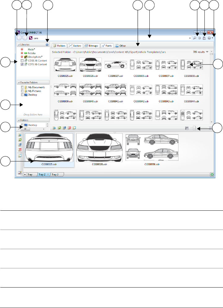
82 Corel DESIGNER X6 User Guide
The image below shows the main components of the Corel CONNECT utility:
Part Description
1. Libraries pane Lets you access content provided by Corel
and Corel partners
2. Favorite folders pane Provides quick access to frequently used
folders
3. Folders pane Displays a representation of the file structure
available on your computer
4. Tr a y pane Lets you collect files from one or more
folders
3
6
2
1
14 13 11 10 9 8
5
4
712
Finding and managing content 83
In docker mode, the search utility has two components: Connect docker and Tr a y
docker. The Connect docker has two viewing modes: single pane and full view. In full
view, all panes are displayed. In single-pane view, either the viewing pane or the
Libraries, Favorite folders, and Folders panes are displayed. You can resize the docker
to display all panes or toggle between the viewing pane and the Libraries, Favorite
folders, and Folders panes.
5. Zoom slider Lets you adjust the size of thumbnails in the
viewing pane
6. Viewing pane Lets you view thumbnails of content files
7. Help and options button Lets you open a menu of commands that
allow you to access Help, configure content
libraries, set preferences, and view version
and license information.
8. Go to parent folder button Lets you go one level up from the current
folder
9. Refresh/Cancel button Reloads the results from your last search or
initiates a new search based on the criteria
that you have specified. When a search is in
progress, the button changes to the Cancel
mode , which allows you to stop a search
at any time.
10. Search and address box Lets you search for files by using search
terms, typing a folder path, or specifying a
Web address
11. Filter toolbar Lets you choose which type of content to
display in the viewing area: folders, vector
images, bitmap images, fonts, or files saved
to file formats that are not supported by the
suite
12. Configure content libraries button Lets you activate access to local and online
content libraries
13. Navigate forward button Takes you to the next page of content
14. Navigate back button Takes you to the previous page of content
Part Description
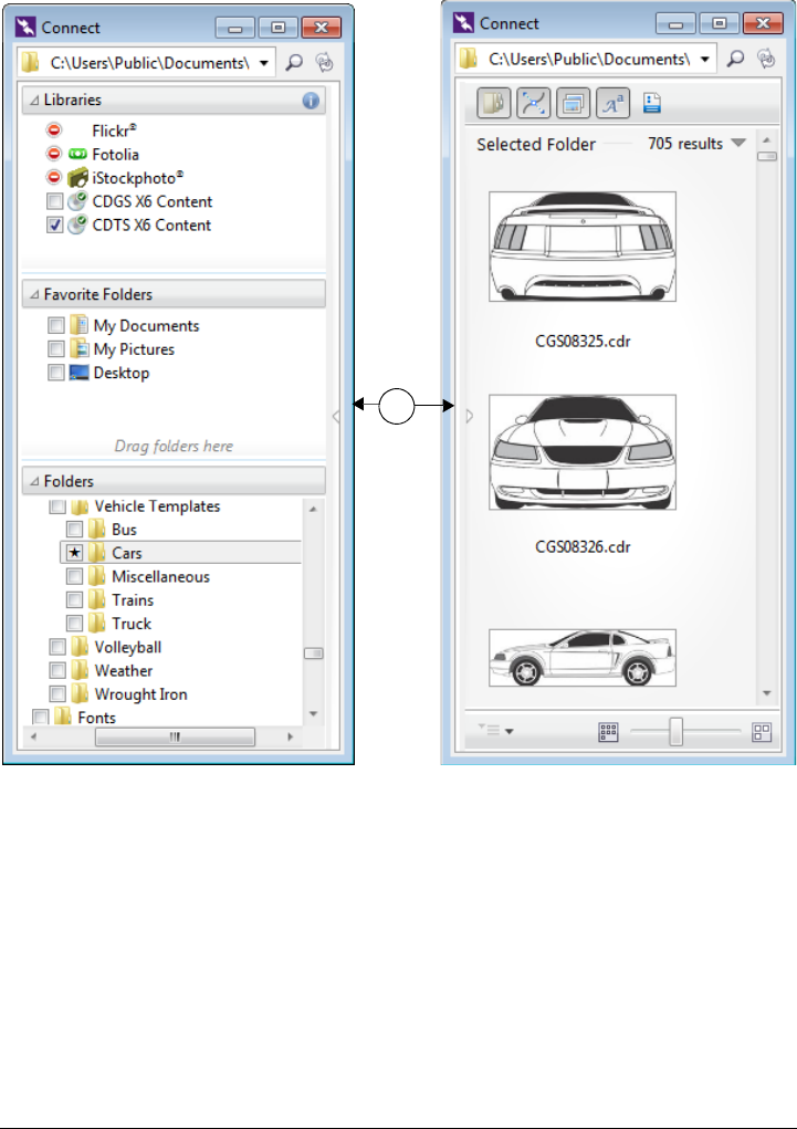
84 Corel DESIGNER X6 User Guide
The Connect docker with the viewing pane hidden (left) and the navigation
pane hidden (right). Click the toggle arrow (1) to display or hide panes. Resize
the docker to display both panes.
You can also customize the size and display of individual panes.
1
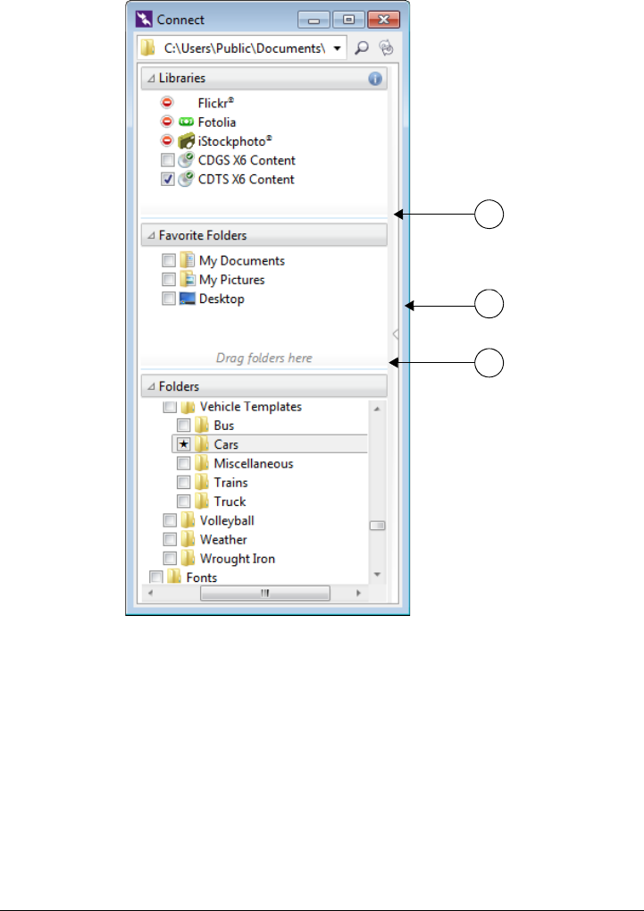
Finding and managing content 85
The grab area (1, 2, 3) lets you resize a pane.
You can use the Favorite folders pane to create shortcuts to folders that you visit
frequently. You can add locations to and remove locations from the Favorite folders
pane.
2
3
1

86 Corel DESIGNER X6 User Guide
To start Corel CONNECT
To resize a pane
• Point to the pane’s grab area, and when the cursor changes to a two-directional
arrow, drag the edge of the pane.
To display or hide a pane
• Click the arrow to toggle between displaying and hiding the pane.
To add a location to the Favorite Folders pane
• Drag a folder from the Libraries, Folders, or viewing pane to the Favorite folders
pane.
You can also add locations to the Favorite folders pane by right-clicking a
folder in the Libraries or Folders pane, and clicking Add to favorites.
To remove a location from the Favorite Folders pane
• Right-click a location in the Favorite folders pane, and click Remove from
favorites.
Accessing content
CorelDRAW Technical Suite provides a content library that contains clipart, fonts,
photos, frames, pattern fills, and more. You can access this content by adding the
To Do the following
Start the standalone utility On the Windows taskbar, click Start All
Programs
CorelDRAW Technical Suite X6
Corel CONNECT X6.
Display or hide the Connect docker In Corel DESIGNER, click Window
Connect.
Display or hide the Tr a y docker In Corel DESIGNER, click Window Tr a y.

Finding and managing content 87
content library to your computer during product installation. The content library is
installed to the Users\Public\Documents\Corel\Content X6 folder, which makes the
content easy to access from Corel DESIGNER, Corel CONNECT, CorelDRAW, and
Corel PHOTO-PAINT. Alternatively, you can access the CorelDRAW Technical Suite
content library from the product DVD.
To access clipart and other content included on a CD or DVD from a previous version
of the software, you must insert the CD or DVD, or browse to the folder to which you
have copied the content.
You can also find content on the Web sites of online content providers such as Flickr®,
Fotolia, and iStockphoto®. You can disable or restore access to a content provider at
any time. The images that you find online are often subject to usage restrictions and
may be watermarked or low-resolution. For information about using such images, see
“Using content” on page 93.
To access online content, you need to agree to the terms and conditions of the content
providers. Note that online content is unavailable in workplaces with restricted Internet
access.
To access a content library stored on a CD or DVD
• Insert the content CD or DVD.
The content library appears in the Libraries pane.
To access a CD or DVD content library that was copied to your computer
1In the Libraries pane, click the Configure content libraries button .
A warning sign next to a content library shows that it needs to be configured.
2Click a content library, click Locate, and browse to the folder where the library is
stored.
The content library appears in the Libraries pane.
To activate access to online content
1In the Libraries pane, click the Configure content libraries button.
2In the viewing pane, click an online content provider.
3Click Activate.
4Review the terms and conditions of the online content provider, and click Accept.

88 Corel DESIGNER X6 User Guide
Browsing and searching for content
With the Corel CONNECT docker, you can browse for content, or you can search for
content by using keywords.
You can browse and search for content in one or multiple locations on your computer
or local network as well as online. You can also navigate to previously viewed content.
Searching for content
You can search by the name, category (for example, clipart, photo images, or fonts), or
reference information (for example, tags or notes) associated with a file. When you type
a term in the Search and address box and initiate a search, all matching files are
displayed as thumbnail images in the viewing pane. For example, if you type flower,
the application automatically filters out all files that do not match, and you see only the
files that have the word flower in the filename, category, or tags assigned to the file.
You can also type phrases and multiple words, and you can fine-tune your search by
using Boolean operators such as AND, NOT, and OR. For example, you can find
content that contains both flower and sun images by typing flowers AND sun.
To increase the search speed for local content and improve results, you can adjust
Windows Search options by adding more locations to the index.
You can also find all images on a Web page by typing the Web address. For example,
typing www.corel.com displays all the images that appear on the Corel Web site.
Refining your search
By default, your search results include all relevant content such as vector graphics,
bitmaps, and fonts. You can narrow the search results by excluding content. For
example, if you are searching for graphics, you can display only vector graphics or only
bitmaps. If you need to choose a font for your project, you can display only fonts.
You can also
Disable access to an online content provider Disable the I have read and agree to the
terms of use of any content sourced from
this content provider check box.
The name of the content provider disappears
from the Libraries pane.
Restore access to an online content provider Click the Configure content libraries
button, and activate access.
Finding and managing content 89
You can widen the scope of a search, and you can cancel a search at any time.
To browse for content
• Click a location in one of the following panes:
• Libraries — lets you browse online and local content
• Favorite folders — lets you browse your favorite locations
• Folders — lets you browse the folder structure available on your computer
You can browse the contents of only one folder at a time.
To search for content
1Click a location in any of the following panes:
• Libraries — lets you search for online and local content as well as content on a
CD or DVD
• Favorite folders — lets you search for content in your favorite locations
• Folders — lets you search for content in the folder structure available on your
computer
2Type a word or multiple words in the Search and address box, and press Enter.
Files that match the search terms appear in the viewing pane.
If you want to search for a phrase, enclose the phrase with quotation marks.
You can also
Specify the location where you want to
browse for content
Type or paste a path in the Search and
address box, and press Enter.
The Search and address bar keeps track
only of the locations that you enter
manually. To delete all locations, click the
drop-down arrow, and click Clear list.
You can also
Search for content in multiple locations Enable the check boxes for the libraries and
folders that you want to search, and click the
Refresh button .
Show or hide search results for a location In the viewing pane, click the Show/Hide
arrow to the right of the location.

90 Corel DESIGNER X6 User Guide
Specify how many online search results to
display
Click an online content provider in the
Libraries pane, and choose a number from
the Search results list box. This number
determines the initial number of search
results that are displayed in the viewing
pane, as well as the additional results that
are displayed each time you click More
from.
Fine-tune a search by using Boolean
operators
Type one of the following Boolean operators
between the search terms:
AND — lets you find content that contains
all search terms in the Search and address
box. Instead of AND, you can also use the
plus sign (+).
NOT — lets you exclude content that
contains the search term after NOT. Instead
of NOT, you can also use the minus sign (-).
OR — lets you find content that contains at
least one of the search terms
Change Windows Search options In the viewing pane, click Configure
Windows search.
You can also
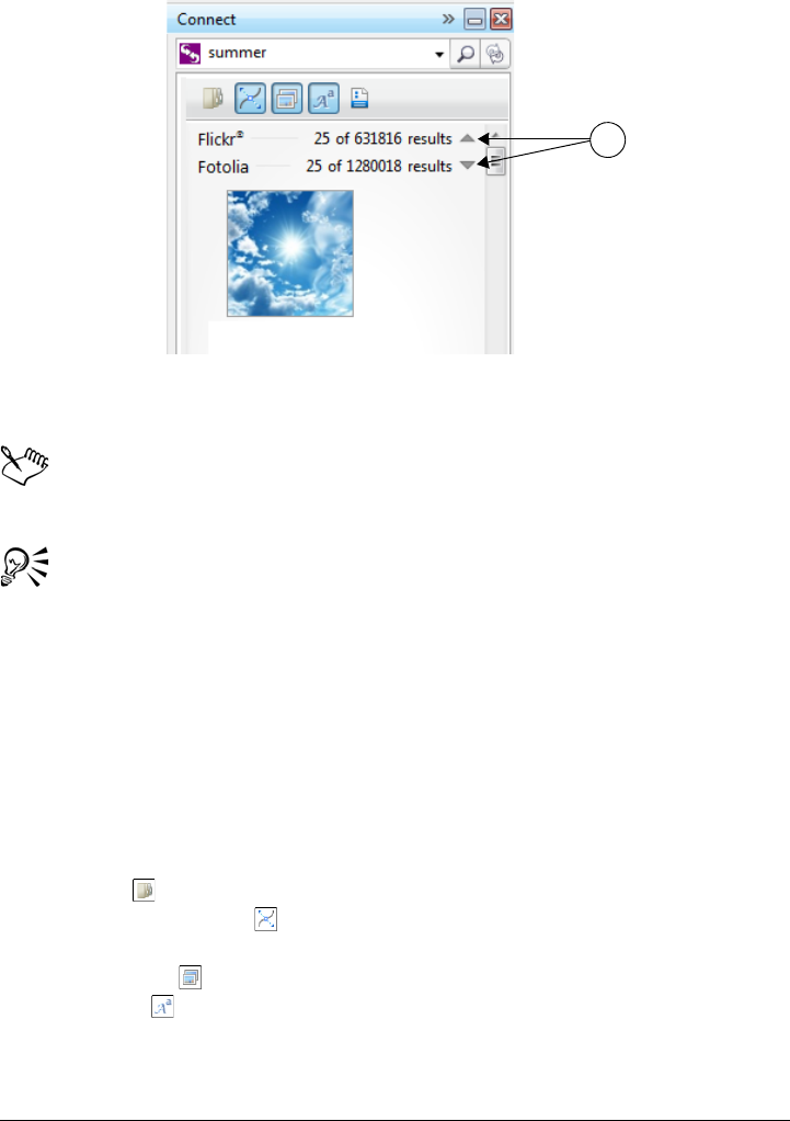
Finding and managing content 91
Clicking a Show/Hide arrow (1) lets you show or hide the search results for
a specific location.
When you search for online content, only vector files and bitmaps are included
in the search results.
If you want to browse the folder where a file is stored or access the source Web
page of an image, right-click the file, and click Open source location.
To find all images on a Web page
• Type a Web address (for example, www.corel.com) in the Search and address
box.
To refine your search
•On the Filter toolbar, click one of the following buttons:
• Folders — to hide or display folders in selected folders
• Vector drawing files — to hide or display vector graphics that are supported
by the suite
• Bitmap files — to hide or display bitmaps that are supported by the suite
• Font files — to hide or display TrueType (TTF), OpenType (OTF), and
PostScript fonts (PFB and PFM)
1
92 Corel DESIGNER X6 User Guide
• Other files — to hide or display file formats that are not supported by the
suite
A category is included in the search results if the button appears pressed.
To navigate to previously viewed content
•Click the Navigate back or Navigate forward button.
You can also go back to the previous search results by pressing Backspace.
You can also navigate to previously viewed content by clicking the Search and
address bar drop-down arrow and choosing a location from the list. The
Search and address bar keeps track only of the locations that you enter
manually.
To stop a search
•Click the Cancel search button .
Viewing content
Clipart, photos, and fonts appear in the viewing pane as thumbnail images. You can
select individual, multiple, or all thumbnails.
By positioning your pointer over a thumbnail, you can display a larger preview. You can
also display file information such as filename, file size, image resolution, and color mode
for content that was not provided by an online content provider. You can also preview
the fonts that you find. Thumbnail zooming makes recognizing a particular file easier
and faster.
To select a thumbnail
• Click a thumbnail.

Finding and managing content 93
To view file information
• Hover over a thumbnail.
To preview a font
• Double-click a font thumbnail.
You can also preview a font by right-clicking a font thumbnail and clicking
Open.
To adjust the size of thumbnails
•Drag the Zoom slider to the left to decrease the size of the thumbnails, or to the
right to increase the size of the thumbnails.
Using content
If you want to view or edit a file before you incorporate it into your project, you can
open it in CorelDRAW, Corel DESIGNER, Corel PHOTO-PAINT, or its associated
application.
You can insert and place content in your document. Images that are obtained from
online sources, such as iStockphoto and Fotolia, may be subject to copyright and usage
restrictions. Such images, also referred to as “comp images,” are often low-resolution or
watermarked. To use comp images, you must first check with the owner if you have
You can also
Select multiple thumbnails Do one of the following:
•Drag around the thumbnails that you
want to select.
•Hold down Ctrl, and in the viewing pane
click the thumbnails that you want to
select.
•Click a thumbnail, and holding down
Shift, click the last thumbnail in the range
that you want to select.
Select all thumbnails Press Ctrl + A.
94 Corel DESIGNER X6 User Guide
rights to use them and purchase them if necessary. Then, you can replace the comp
images in your document with the purchased images. You can also view a list of all comp
images in a document.
In addition, in Corel CONNECT, you can perform many tasks (such as renaming,
printing, compressing, emailing, and faxing files) that are available through the
Windows operating system. Right-click a file in the viewing pane, and choose a
command.
To open a file
• Select a thumbnail, and choose an action from the following table.
You can also open a file by right-clicking it and choosing the option that you
want.
You can also open multiple selected files.
To Do the following
Open a file by using the Corel CONNECT
utility
Click one of the following buttons:
•Open — lets you open a file in the
application it is associated with or navigate
to the source Web page of an online image
•Open in CorelDRAW or Import in
CorelDRAW — lets you open or
import a file in CorelDRAW
•Open in Corel DESIGNER or Import in
Corel DESIGNER — lets you open or
import a file in Corel DESIGNER
•Open in Corel PHOTO-PAINT
— lets you open a file in
Corel PHOTO-PAINT
Open a file by using the Connect docker Do one of the following:
•In full view, click the Open button .
•In single pane view, click the File
commands button , and click Open.
Open a file by using the Tr a y docker Click the Open button .
Finding and managing content 95
To insert a file into an active document
You can also insert a file into an active document by dragging the file from the
viewing pane or the Tr a y docker to the active document.
To Do the following
Insert a file into an active document by using
the Corel CONNECT utility
Drag a file from the Tr a y or viewing pane to
the active document.
Insert a file into an active document by using
the Connect docker
Do one of the following:
•Drag a file from the viewing pane of the
Connect docker to the active document.
•In single pane view, select a file in the
viewing pane, click the File commands
button , click Import, and click in your
document.
•In full view, select a file in the viewing
pane, click the Import button , and
click in your document.
Insert a file into an active document by using
the Tr a y docker
Select the file, and click one of the following
buttons in the Tr a y docker:
•Import — lets you insert a file as an
embedded object
•Import and link — lets you insert a
file as a linked object
•Import at original position — lets you
import and place a vector graphic at the
original position it was created relative to
the page
Note that the Import buttons are not
available in the standalone utility.
Insert and place a vector graphic in a
document
Click the Import or Import and link
button and do one of the following:
•Drag to place and resize the graphic.
•Press Enter to center the graphic on page.
•Press Spacebar to place the vector graphic
at the original position it was created
relative to the page.

96 Corel DESIGNER X6 User Guide
You can also insert a file into an active document by right-clicking the file in
the viewing pane and choosing an import command.
You can also insert multiple selected files.
To check, purchase, and replace a comp image
1In your document, right-click a comp image, and click Open comp source.
2On the Web site of the online content provider, check the copyright and usage
restrictions for the image, and purchase it if necessary.
3In your document, right-click a comp image, and click Replace comp.
4Navigate to the purchased image, and click Import.
Transformations, such as scaling, rotating, and resizing, that were applied to
the comp image are preserved in the final image.
To view a list of all comp images in a document
• Open a document, and do one of the following:
• Click File Print, click the Preflight (Issues) tab, and click Some images may
be subject to copyright and usage restrictions.
• Click File Document properties.
When you export a document to the Adobe Illustrator (AI), Scalable Vector
Graphics (SVG), HTML, or PDF file format, you can view a list of all comp
images in the preflight summaries.
Installing pattern fills and fonts
You can install bitmaps and vector graphics (clipart) that you find as pattern fills for
future use. You can also install the fonts that you find.
For information about finding pattern fills and fonts, see “To browse for content” on
page 89 and “To search for content” on page 89.
Finding and managing content 97
To install content as a pattern fill
Bitmap pattern fills are installed to the Users\[UserName]\My
Documents\Corel\Corel Content\Bitmap Patterns folder.
Vector pattern fills are installed to the Users\[UserName]\My
Documents\Corel\Corel Content\Vector Patterns folder.
To install a font
1In Corel CONNECT or the Connect docker, browse to or search for the font that
you want to install.
2In the viewing pane, right-click the font thumbnail, and click Install.
A check mark appears in the lower-right corner of the font thumbnail to show that
the font is installed.
To uninstall a font, right-click the font thumbnail, and click Uninstall.
Managing content
You can organize your content by using trays or by adding content files to specific
folders on your computer.
A tray is useful for gathering content from various folders. While the files are referenced
in the tray, they actually remain in their original location. You can add and remove
content from the tray. The tray is shared between CorelDRAW, Corel DESIGNER,
Corel PHOTO-PAINT, and Corel CONNECT. You can also open files from the tray to
preview them more easily.
To install Do the following
A bitmap pattern fill In the viewing pane of Corel CONNECT or
the Connect docker, right-click the
thumbnail of a bitmap, and click Install as
bitmap pattern.
A vector pattern fill In the viewing pane, right-click the
thumbnail of a vector graphic, and click
Install as vector pattern.
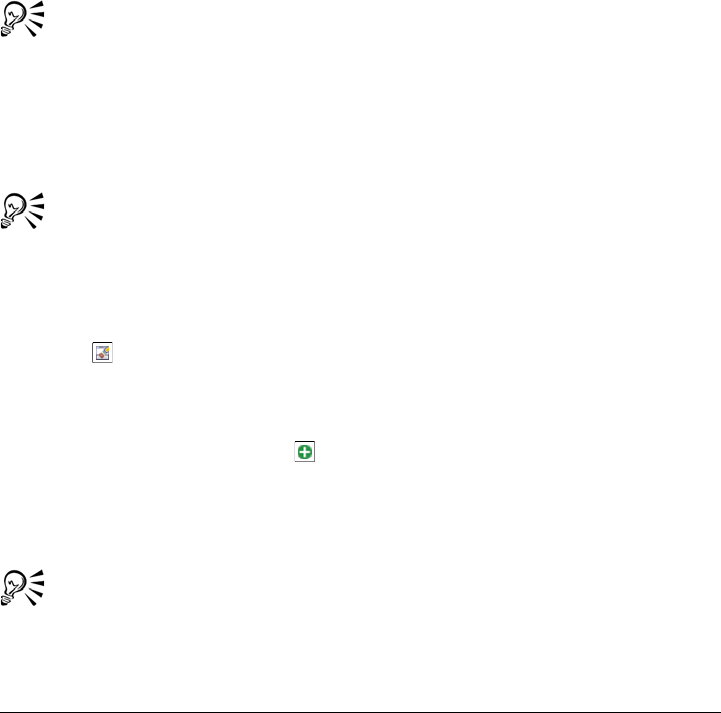
98 Corel DESIGNER X6 User Guide
You can create trays so that you can organize your content. Trays are saved to your user
folder with .Tray file extensions. You can change the default folder to which trays are
saved. For example, you can save a tray to a network folder to share it with others.
You can rename trays to give them meaningful names. When working with multiple
trays, you can close some trays temporarily to avoid clutter. You can easily reopen a tray
when you need it. In addition, you can load a tray file that is not listed among the
available trays. You can delete a tray at any time.
To add content to a tray
• Select one or more thumbnails in the viewing pane, and drag them to the tray.
If you want to open a file from the tray, double-click its thumbnail.
You can also drag content from a folder on your computer to the tray.
To add content to a folder
• Select one or more thumbnails in the viewing area, and drag them to a folder in the
Favorite folders or Folders pane, or any other folder on your computer.
You can drag content from the tray to a folder.
To remove content from a tray
• Select one or more thumbnails in the tray, and click the Remove from tray
button .
To create a tray
•Click the Add new tray button , which is located in the lower-right corner of the
tray pane.
By default, a tray is saved to the Users\[UserName]\My
Documents\Corel\Corel Content\Trays folder.
You can email trays that contain only online content.

Finding and managing content 99
To change the folder to which trays are saved
1In the standalone utility, click the arrow on the Help and options button, and
click Options.
2Type a path in the Default tray location box.
To browse to a folder, click the Browse button next to the Default tray
location box.
To share a tray, you can save it to a network folder.
To work with trays
You can also close and delete a selected tray from the All trays menu.
To Do the following
Select a tray Click the tray tab.
Rename a tray Right-click the tray tab, click Rename, and
type a new name.
Open a tray Click the All trays arrow, and click a tray.
An open tray has a check mark beside its
name.
Close a tray Right-click the tray tab, and click Close.
Load a tray file Click the All trays arrow, click Open tray
file, and navigate to the tray file.
Navigate through multiple trays Holding down Ctrl, press Ta b .
Delete a tray Right-click the tray tab, and click Delete.

Working with precision 101
Working with precision
Precision is essential when you work with technical graphics. With Corel DESIGNER,
you can create precise objects and position them accurately by using gravity snapping,
constrain keys, dynamic guides, and object coordinates.
When you draw or modify objects, gravity snapping lets you specify the exact
placement of a point. If you want to constrain an object to a particular shape as you
draw, or control the angle of lines, you can use constrain keys. For example, when
drawing a rectangle, you can use constrain keys so that the rectangle is drawn as a
square.
You can use these features for all drawing and editing operations. For example, before
rotating an object, you can snap the center point to the corner of another object and
then rotate the object around that point.
Dynamic guides, which are temporary guidelines that you can display from eligible snap
points in objects, help you draw and position objects with precision. In addition, you
can draw and modify objects by specifying object coordinates.
This section contains the following topics:
• Using gravity snapping
• Using dynamic guides
• Using alignment guides
• Using constrain keys
• Using object coordinates
Using gravity snapping
Gravity snapping is the attraction of the pointer to a snap point. Snap points are precise
mathematical drawing coordinates. When the pointer approaches a snap point, the
gravity source of the snap point is highlighted. The highlighting identifies the snap
point as the target that the pointer will snap to. Snap points are also known as “gravity-
snapping candidates.”
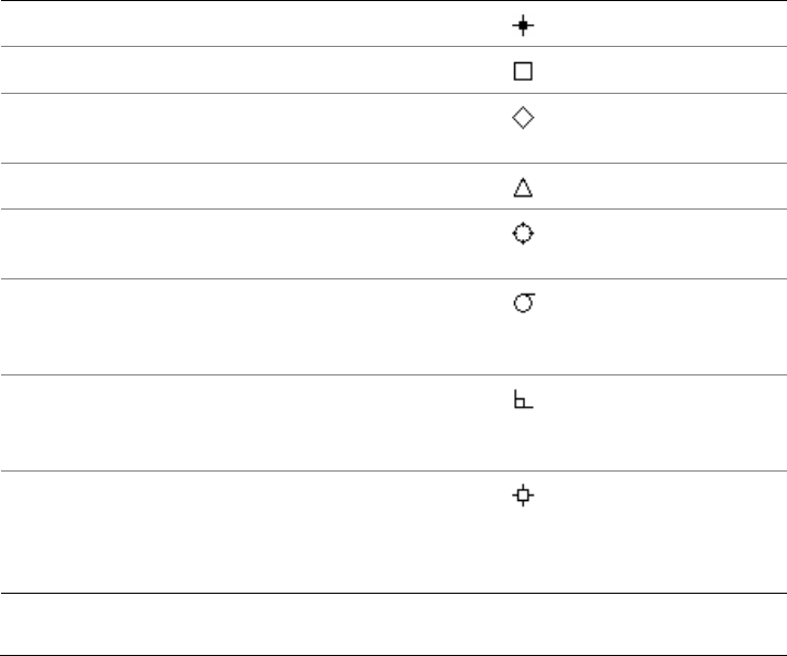
102 Corel DESIGNER X6 User Guide
The gravity field of each snap point has a radius of 10 screen pixels (not document
pixels) by default. When the pointer enters a gravity field, a gravity source indicator
appears around the point, and the name of the gravity source appears on the screen. You
can turn gravity snapping on and off.
Gravity shortcut keys let you activate a single type of gravity snap. By default, gravity
shortcut keys are the first letters in the names of gravity-snapping candidates. When
you hold down a gravity shortcut key, all other gravity snap points become inactive. For
example, if you hold down the M key, only the Midpoint gravity snap point is active.
If the pointer is within the gravity fields of two or more gravity-snapping candidates,
the gravity-snapping candidate closest to the pointer has priority. If the gravity-
snapping candidates are the same distance from the pointer, the pointer snaps to the
gravity-snapping candidate with the higher priority, as listed in the following table.
Gravity-snapping
candidate Description
Gravity
source
indicator
Gravity
shortcut
key
Pixel Point on the pixel grid S
Node Node on an object N
Intersection Geometric intersection of line
segments, arcs, or guidelines
I
Midpoint Midpoint of line segment M
Quadrant Points that are at 0°, 90°, 180°,
and 270° on a circle, ellipse, or arc
Q
Tangent Point on the outside edge of an arc,
circle, or ellipse where a line will
touch but not intersect the object
T
Perpendicular Point on the outside edge of a
segment where a line will be
perpendicular to the object
P
Edge Point that touches the nearest
perpendicular edge (shortest
perpendicular distance from the
pointer to the edge)
E
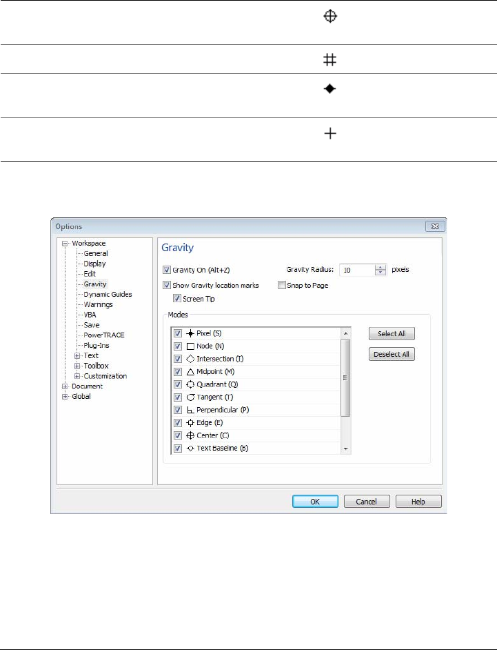
Working with precision 103
You can make gravity-snapping candidates active or inactive and set other options to
customize snapping.
Corel DESIGNER lets you control how gravity snapping works.
To turn gravity snapping on or off
1Click To o l s Gravity.
2Enable or disable the Gravity on check box.
Center Center of the closest object (arc,
regular polygon, or curve centroid)
C
Grid Visible or invisible grid point G
Text baseline Point in the baseline of artistic or
paragraph text
B
Absolute Pointer location; temporarily
suspends all gravity snaps
A
Gravity-snapping
candidate Description
Gravity
source
indicator
Gravity
shortcut
key

104 Corel DESIGNER X6 User Guide
You can also toggle gravity snapping on and off by pressing Alt + Z.
To use gravity snapping
1Move the pointer close to where you want to snap.
2Click when the gravity source becomes highlighted.
If you are dragging to draw a line or select an object, release the mouse button.
To set gravity options
1Click To o l s Gravity.
2Perform one or more tasks from the following table.
You can also
Snap an object to another object Drag an object close to where you want to
snap. When the gravity source becomes
highlighted, release the mouse button.
Snap to guidelines Move the pointer to the edge of a guideline
or to the intersection of two guidelines.
To turn off snapping to guidelines, click
Tools Gravity, and disable the Edge mode
on the Gravity page of the Options dialog
box.
To Do the following
Activate snapping objects to page elements
(edges, edge midpoints, and page center)
Enable the Snap to page check box.
Activate a gravity-snapping candidate In the Modes area, enable the corresponding
check box.
Activate all gravity-snapping candidates Click Select all.
Disable all gravity-snapping candidates
without turning off gravity snapping
Click Deselect all.
Display gravity source indicators Enable the Show gravity location marks
check box.
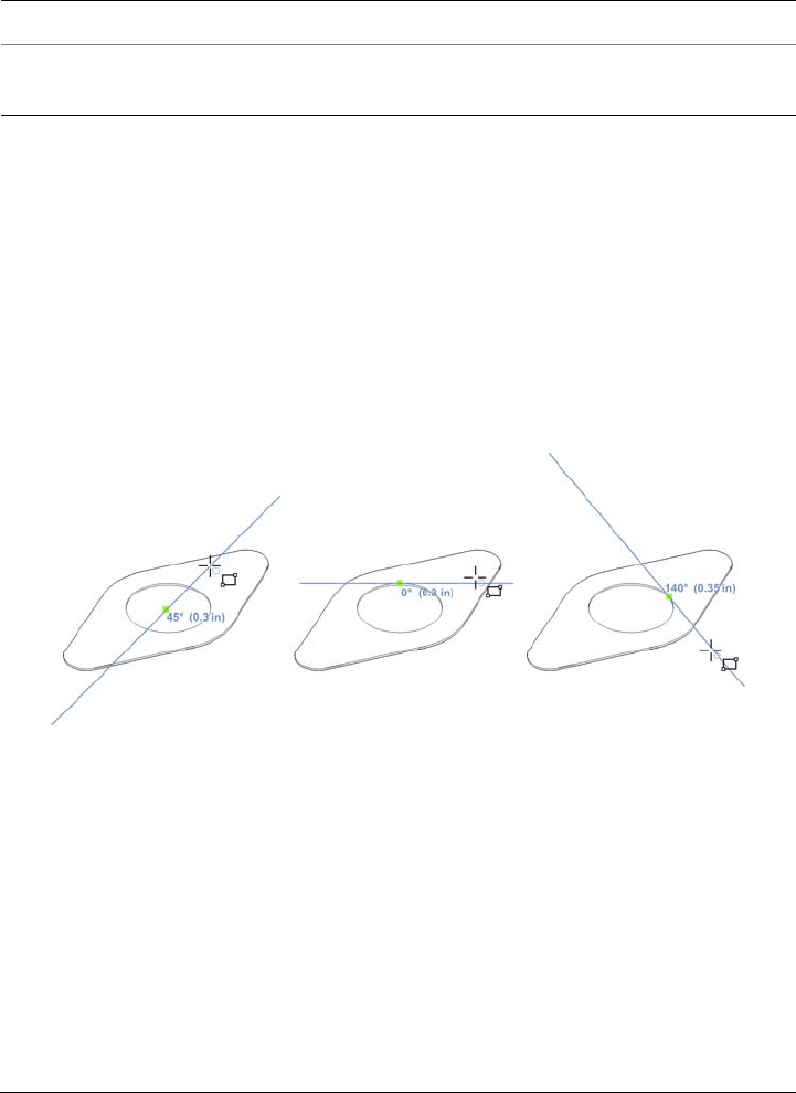
Working with precision 105
Using dynamic guides
You can display dynamic guides to help you move, align, and draw objects in precise
relation to other objects. Dynamic guides are temporary guidelines that you can display
from the following snap points in objects: center, node, quadrant, and text-baseline end
nodes. For more information about snap points and snapping modes, see “Using gravity
snapping” on page 101.
You can also display dynamic guides that are tangent, perpendicular, or parallel to
objects, as well as dynamic guides that are extensions of line segments.
Left to right: The 2-point rectangle tool is used to display dynamic guides
from a center snap point, a quadrant snap point, and a tangent snap point.
Display the name of the gravity source Enable the Screen tip check box.
Change the size of the gravity field around
gravity-snapping candidates
Type a value in the Gravity radius box.
To Do the following
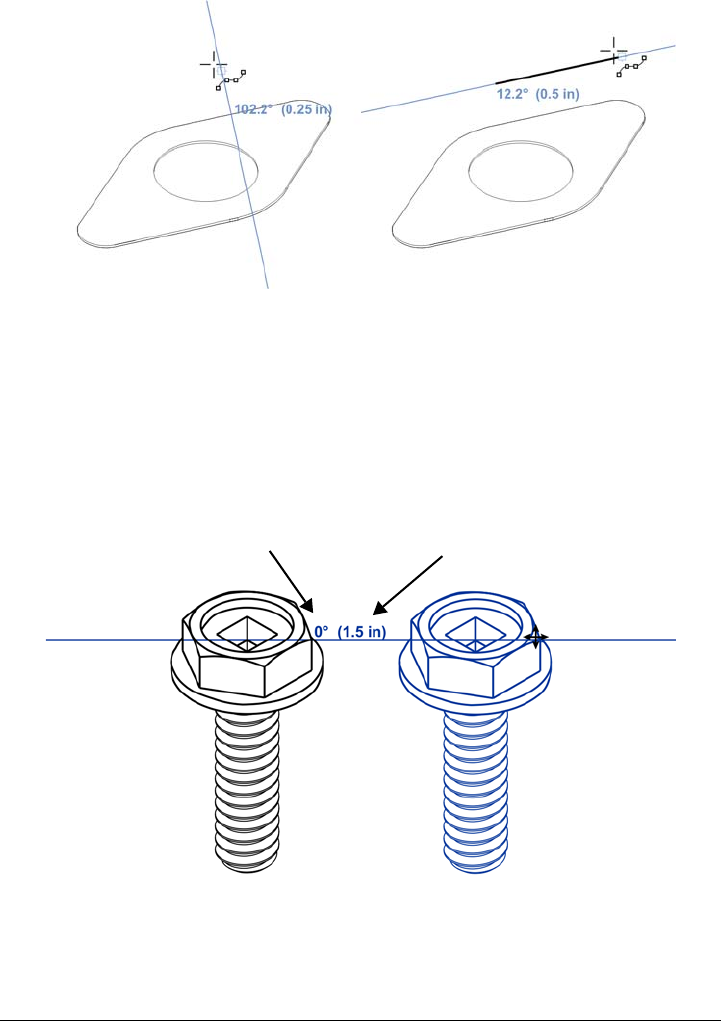
106 Corel DESIGNER X6 User Guide
Perpendicular dynamic guide (left) and parallel dynamic guide (right)
As you drag an object along a dynamic guide, you can view the distance between the
object and the snap point that was used to create the dynamic guide. You can then
position the object precisely. Dynamic guides can also help you draw parallel lines and
draw objects in relation to other objects. In addition, you can display intersecting
dynamic guides and place an object at the intersection point.
A dynamic guide was displayed from a node in the bolt on the left. The screen
tip next to the node displays the angle of the dynamic guide(0º) and the
distance between the node and the pointer (1.5 inches). The bolt on the right
was dragged along the dynamic guide and positioned precisely 1.5 inches away
from the node that was used to generate the dynamic guide.
Angle screen tip Distance screen tip
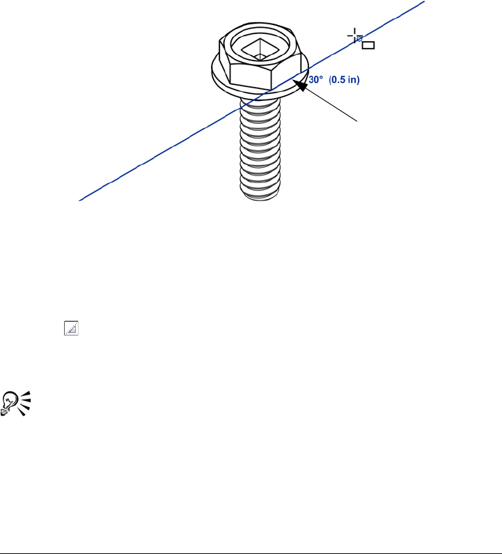
Working with precision 107
Dynamic guides contain invisible divisions, called ticks, to which your pointer
gravitates. Ticks let you move objects along a dynamic guide with precision. You can
adjust tick spacing to suit your needs, and you can disable snapping to ticks. You can
set other options for dynamic guides. For example, you can choose to display dynamic
guides at one or more preset angles or at custom angles that you specify. You can
preview the angle settings. You can also customize the color and line style of dynamic
guides. When you no longer need a dynamic guide at a certain angle, you can delete the
angle settings. You can also display dynamic guides that are extensions of line segments.
This dynamic guide is an extension of a line segment.
You can turn off dynamic guides at any time.
To enable or disable dynamic guides
1Click To o l s Alignment and dynamic guides, and click the Dynamic guides
button .
2In the Alignment and dynamic guides docker, enable or disable the check box in
upper-right corner of the Dynamic guides section.
You can toggle dynamic guides on and off by pressing Shift + Alt +D.
To display dynamic guides
1With dynamic guides enabled, click a drawing tool.
2Move the pointer over and then off a node, center, quadrant, or text-baseline snap
point of an object.
Line segment

108 Corel DESIGNER X6 User Guide
3Repeat step 2 with other objects to display other dynamic guides.
The snap points you point to are registered in a queue and used to create dynamic
guides.
You can also Do the following
Display a dynamic guide that is a tangent to
the edge of an object
Move the pointer over the edge of an object.
When an edge snap point becomes
highlighted, press H. Then, display the
dynamic guide by moving the pointer off the
snap point as if to draw a tangent.
Display a dynamic guide that is
perpendicular to an object
Move the pointer over the edge of an object.
When a snap point becomes highlighted,
press U. Then, display the dynamic guide by
moving the pointer off the snap point as if to
draw a perpendicular line.
Display a dynamic guide that is parallel to a
line segment
Click To o l s Alignment and dynamic
guides, click the Dynamic guides button,
and ensure that the Generate parallel
guides button is enabled. Start to draw a
straight line, and then move the pointer over
the edge of an existing line segment to
register the angle. Then, display the
dynamic guide by moving the pointer back
as if to draw a line parallel to the line
segment you just pointed to.
You can use the 2-point line tool , Multi-
point line tool , or 3-point rectangle
tool to display parallel dynamic guides.
Display a dynamic guide that is an extension
of a line segment
Click To o l s Alignment and dynamic
guides, click the Dynamic guides button,
and click the Extend along segment
button. Move the pointer over an end node
in the line segment until the snap point
becomes highlighted. Then, display the
dynamic guide by moving the pointer as if to
extend the line segment.

Working with precision 109
The node, center, quadrant, and text-baseline snap points appear only when
the corresponding gravity modes are activated. For more information about
snap points and gravity modes, see “Using gravity snapping” on page 101.
You can avoid displaying too many dynamic guides by clicking in the drawing
window or by pressing Esc. Either of these actions clears the queue of points.
You can use the snap points you registered to display intersecting dynamic
guides. First, display a dynamic guide, and then move the pointer along it to
where an intersecting dynamic guide would be displayed from a registered snap
point.
To position an object in relation to another object
1With dynamic guides enabled, select an object.
2Drag the object to a node, center, quadrant, or text-baseline snap point of the
target object.
3When the snap point of the target object becomes highlighted, drag the object
along the dynamic guide to position it.
The node, center, quadrant, and text-baseline snap points are displayed only
when the corresponding gravity modes are activated. For more information
about snap points and gravity modes, see “Using gravity snapping” on
page 101.
To draw an object in relation to another object
1With dynamic guides enabled, click a drawing tool.
2Move the pointer over a node, center, quadrant, or text-baseline end-node snap
point of an object.
3When the snap point becomes highlighted, move the pointer to display a dynamic
guide.
4Move the pointer along the dynamic guide to the point where you want to draw,
and drag to draw an object.
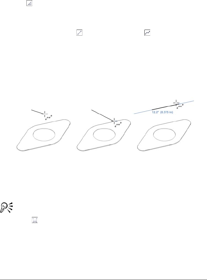
110 Corel DESIGNER X6 User Guide
To draw parallel lines
1Click To o l s Alignment and dynamic guides, and click the Dynamic guides
button .
2Ensure that the Generate parallel guides button is enabled.
3Draw a straight line or an object that contains straight line segments.
4Using the 2-point line tool or Multi-point line tool , start to draw another
straight line, and then move the pointer over the edge of an existing straight line
segment.
5Move the pointer back to where you want to draw the parallel line.
6When a parallel dynamic guide appears, continue to drag along the guide until the
line is the length you want.
To draw a parallel line, start drawing a straight line (left). Next, move the
pointer over the edge of a straight line segment (middle). Finally, move the
pointer back until a parallel dynamic guide appears, and drag along the guide
until the parallel line is the length you want (right).
With the help of parallel dynamic guides, you can use the 3-point rectangle
tool to draw rectangles that are parallel to straight line segments.
To position an object at the intersection of dynamic guides
1With dynamic guides enabled, select an object.
If you want to move the object by a specific snap point, move the pointer over the
snap point until the point becomes highlighted.
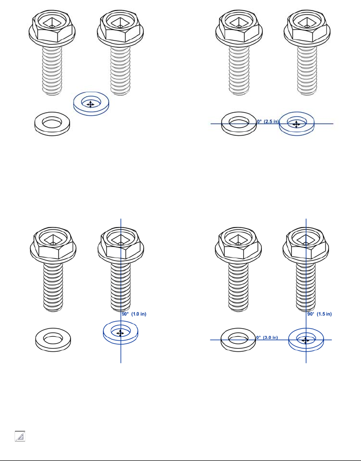
Working with precision 111
2Drag the object to an eligible snap point on another object, and continue to drag
until a dynamic guide appears.
Don’t release the mouse button.
3Drag the object to another eligible snap point, and don’t release the mouse button.
4When the snap point becomes highlighted, continue to drag until another dynamic
guide appears where the two dynamic guides would intersect.
5When the intersection point appears, release the mouse button.
To set options for dynamic guides
1Click To o l s Alignment and dynamic guides.
2In the Alignment and dynamic guides docker, click the Dynamic guides button
.

112 Corel DESIGNER X6 User Guide
3Perform one or more tasks from the following table.
Using alignment guides
You can align objects interactively on the drawing page by using alignment guides.
Alignment guides are temporary guidelines that appear when you create, resize, or
move objects in relation to nearby objects. While dynamic guides provide precise
measurements for creating technical illustrations, alignment guides are useful in page
layout to align text or graphic elements quickly and accurately.
To Do the following
Change the line style of dynamic guides Open the Line style picker, and choose a
line style.
Change the color of dynamic guides Open the Line color picker, and choose a
color.
Display or hide the angle of dynamic guides
and the distance from the snap point that
was used to create the dynamic guide
Click the Display screen tips button .
Snap to specified invisible divisions along the
dynamic guide
Click the Snap to tick spacing button ,
and type a value in the Tick spacing box.
Choose the angles at which to display the
dynamic guides
Enable or disable the angle check boxes.
When you enable an angle check box, a
preview of the dynamic guide appears in the
Guides preview window.
Add a custom dynamic guide angle Type a value in the Custom angle box, and
click the Add custom angle button .
Delete a custom dynamic guide angle Select a dynamic guide in the list, and click
the Delete custom angle button .
Display dynamic guides at all available
angles
Click the Select all button .
Disable dynamic guides at all available
angles
Click the Deselect all button .
Working with precision 113
Alignment guides appear as an object is moved.
Alignment guides help you align the centers and edges of objects. If you want to align
an object at a set distance from the edge of another object, you can set margins for the
alignment guides. You can display the margin alignment guides in addition to other
alignment guides, or disable all other alignment guides and show only the margin
alignment guides.
Margin alignment guides let you use offset margins, inset margins, or both. There are
separate controls for horizontal and vertical margin alignment guides, so you can
modify settings for one without affecting the other.
You can offset (left) and inset (right) margin alignment guides.
Alignment guides are turned off by default. You can easily enable or disable alignment
guides, or modify their default settings, including the color and line style. You can
choose whether alignment guides appear for individual objects in a group, or for the
bounding box of the group as a whole.
114 Corel DESIGNER X6 User Guide
The Intelligent Spacing feature lets you precisely arrange and position an object in
relation to other onscreen objects, and the Intelligent Dimensioning feature lets you
intuitively scale and rotate an object in relation to other onscreen objects.
Intelligent Dimensioning displays indicators when an object is rotated to the
same angle (top) or scaled to same size (bottom) as the closest object.
Intelligent Spacing displays indicators when an object is equidistant from two
other objects (left) or has the same spacing as the closest onscreen objects (right).

Working with precision 115
To enable or disable alignment guides
1Click To o l s Alignment and dynamic guides.
2In the Alignment and dynamic guides docker, click the Alignment guides
button .
3Enable or disable the check box in the upper-right corner of the Alignment guides
section.
You can also enable or disable alignment guides by clicking the Alignment
guides button on the Layout toolbar. To open the Layout toolbar, click
Layout Layout toolbar or View To o l b a r s Layout.
You can also enable alignment guides by pressing Shift + Alt + A.
To modify alignment guide settings
1Click To o l s Alignment and dynamic guides.
2In the Alignment and dynamic guides docker, click the Alignment guides
button .
3Perform any of the following tasks.
To Do the following
Change the color of alignment guides Open the Line color picker, and choose a
color.
Change the line style of alignment guides Open the Line style picker, and choose a
line style.
Set guides to align the edge of an object with
the edge of another object
Click the Object edges button .
Set guides to align the edge of an object with
the center of another object
Click the Object centers button .
Set guides to align to individual objects in a
group
Click the Individual objects in a group
button .
Distribute objects using the same spacing as
the closest onscreen objects
Ensure that the Intelligent spacing button
is enabled, and drag the object until
indicator arrows appear.
116 Corel DESIGNER X6 User Guide
You can access some alignment guide controls on the Layout toolbar by
clicking the Layout toolbar button .
To add margin alignment guides
1Click To o l s Alignment and dynamic guides.
2In the Alignment and dynamic guides docker, click the Alignment guides
button .
3Perform any of the following tasks.
Position an object equidistantly between two
other objects
Ensure that the Intelligent spacing button
is enabled, and drag the object between two
other objects until indicator arrows appear.
Scale objects to the same dimensions as other
onscreen objects
Ensure that the Intelligent dimensioning
button is enabled, and scale the object
until indicator arrows appear.
Rotate objects to the same angle as other
rotated onscreen objects
Ensure that the Intelligent dimensioning
button is enabled, and rotate the object until
rotation indicators appear.
To Do the following
Add margin alignment guides Enable the Margins check box. If the
Margins check box is not displayed, click
the arrow button located at the bottom
of the Alignment guides section.
Change the line color of margins Open the Margin line color picker, and
choose a color.
Change the line style of margins Open the Margin line style picker, and
choose a line style.
To Do the following

Working with precision 117
Set horizontal margins Type a value in the Horizontal margin box,
click the Horizontal margin button, and
choose one of the following options:
•Offset horizontally — creates a
margin of the specified distance around an
object
•Inset horizontally — creates a margin
of the specified distance within an object
•Offset and inset horizontally —
creates margins of the specified distance
around and within an object
Set vertical margins Type a value in the Vertical margin box,
click the Vertical margin button, and
choose one of the following options:
•Offset vertically — creates a margin
of the specified distance around an object
•Inset vertically — creates a margin of
the specified distance within an object
•Offset and inset vertically — creates
a margin of the specified distance around
and within an object
Lock the ratio between vertical and
horizontal margins
Click the Lock ratio button
View only margin alignment guides Disable the Object edges button , the
Object centers button , the Intelligent
spacing button , and the Intelligent
dimensioning button .
Disable horizontal margins Click the Horizontal margin button, and
choose No horizontal margin .
Disable vertical margins Click the Vertical margin button, and
choose No vertical margin .
To Do the following

118 Corel DESIGNER X6 User Guide
Using constrain keys
Constrain keys let you restrict how objects are drawn or edited. For example, when
drawing a line, you can constrain it to be perfectly horizontal or vertical. You can also
change which key is used as the constrain key. You can change the constrain key from
Ctrl to Shift, which is the Windows standard.
To constrain an object while drawing or editing
• Start drawing or editing, and hold down the Ctrl key.
If you are drawing or editing a line, the pointer movement is restricted to the
specified constrain angle. If you are drawing or editing an object, the shape of the
object is restricted.
A rectangle is constrained to a square, an ellipse to a circle, and a polygon to a
shape that has sides of equal length.
To change the direction of a line that you’re drawing, release Ctrl, and move
the pointer in the direction you want. Then, hold down Ctrl again to restrict
movement of the pointer to the constrain angle.
To change the constrain angle, click To o l s Options. In the Wor ks p ac e list
of categories, click Edit, and type a value in the Constrain angle box.
To change the constrain key
1Click To o l s Options.
2In the Wo rk s pa ce, To o l b o x list of categories, click Pick tool.
3Enable one of the following options:
• Traditional Corel DESIGNER: Ctrl = Constrain, Shift = Transform from
center — sets the Ctrl key as the constrain key
• Windows standard: Ctrl = Duplicate/Leave original, Shift = Constrain —
sets the Shift key as the constrain key
Working with precision 119
Using object coordinates
You can use the Object coordinates docker to draw and modify shapes and lines with
precision. The live preview in the drawing window lets you see the effects of your
adjustments.
Yo u c a n t y p e c o o r d i n a t e v a l u e s to specify the exact position, dimensions, and angle of
rotation of an object. You can also set object attributes interactively by dragging in the
drawing window.
Drawing rectangles and squares
To draw a rectangle with precision, you can specify an origin point, which is one of nine
points in the rectangle (four corner points, four midpoints, and one center point). If you
rotate the rectangle, the origin point is used as the center of rotation. You can also
specify the angle of rotation, and the width and height of a rectangle.
If the angle of rotation is 0, you can specify the position of the lower-left and upper-
right corners of the rectangle.
To draw a square, you can specify the origin point, the length of a side, and an angle of
rotation.
Left: The origin point of a rectangle appears as a blue node in the live preview.
You can select the center point, or any corner or midpoint, as the origin point.
Drawing ellipses and circles
To draw an ellipse with precision, you can specify an origin point, which is one of nine
points in the bounding box that can be drawn around the ellipse. The origin point is
used as the center of rotation.
You can also specify the ellipse diameters, which are the width and height of the
bounding box around the ellipse, and the angle of rotation. If the angle of rotation is 0,
120 Corel DESIGNER X6 User Guide
you can specify the exact position of the lower-left and upper-right corners of the
bounding box around the ellipse.
To draw a circle, you can specify the origin point, diameter, and angle of rotation.
You can specify the width and height of the bounding box that can be drawn
around an ellipse.
Drawing polygons
To draw a polygon, you can specify the number of sides, the angle of rotation, or the
center and diameters of the bounding ellipse that can be drawn around the polygon.
The center of the bounding ellipse, also known as the “polygon center,” is used as the
center of rotation.
You can also draw regular polygons with precision. All sides of a regular polygon are of
equal length. You can specify the side length and angle of rotation, or the center and
diameter of the bounding circle that can be drawn around the regular polygon.
You can specify the diameters of the bounding ellipse that can be drawn around
the polygon.
Working with precision 121
Drawing lines
You can draw a straight line by using one of two methods. With the first method, you
specify the start point and endpoint of the line. With the second method, you specify
the start point and length of the line, plus an angle of rotation.
You can create complex lines by specifying the coordinates of multiple points. You can
delete points, and you can modify the coordinates of existing points. After adding all
the points you want, you can close the curved line by connecting its start point to its
endpoint.
Straight and multipoint lines
Modifying existing objects
You can use the Object coordinates docker to modify existing objects with precision.
Note that when you modify an existing object, it is replaced with a new object. As a
result, the following transformations and effects applied to the original objects are lost:
envelope effects, rotations, and skew effects. In addition, any changes that were
previously applied to the nodes on a polygon are lost.
To draw or modify a rectangle by using object coordinates
1Click Window Object coordinates.
If you want to modify an existing rectangle, select the rectangle.
2Click the Rectangle button .
3Make any of the following adjustments:
• To set the origin point of the rectangle, click a point in the Origin area.
• To specify the exact position of the origin point, type values in the x and y boxes.
• To specify the width and height of the rectangle, type values in the Object size
boxes.

122 Corel DESIGNER X6 User Guide
• To specify only the height or width of the rectangle and have the other
dimensions automatically adjusted in proportion, enable the Proportional check
box.
• To rotate the rectangle at a specified angle, type a value in the Angle of rotation
box. The origin point of the rectangle is used as the center of rotation.
4Click one of the following:
• Create object — adds a new rectangle to the drawing window
• Replace object — replaces the selected rectangle with a new one
To draw or modify a square by using object coordinates
1Click Window Object coordinates.
If you want to replace an existing square, select the square.
You can also
Draw a rectangle by specifying the exact
position of its lower-left and upper-right
corners
In the Bounding box area, type values in
the x and y boxes.
The first pair of boxes controls the position
of the lower-left corner. The second pair
of boxes controls the position of the
upper-right corner.
This method for drawing rectangles is
available only when no rotation is applied.
Set the lower-left and upper-right corners of
a rectangle directly in the drawing window
In the Bounding box area, click the Set
lower-left corner interactively button or
the Set upper-right corner interactively
button , and click in the drawing window.
Set the origin point directly in the drawing
window
Click the Set origin point interactively
button , and click in the drawing window.
Specify the dimensions of the rectangle
directly in the drawing window
Click either of the Set dimensions
interactively buttons , and drag in the
drawing window.
Set the angle of rotation directly in the
drawing window
Click the Set angle interactively button ,
and drag in the drawing window.
Working with precision 123
2Click the arrow at the bottom of the Rectangle button, and click the Square
button .
3Make any of the following adjustments:
• To set the origin point of the square, click a point in the Origin area.
• To specify the exact position of the origin point, type values in the x and y boxes.
• To specify the length of a side, type a value in the Object size box.
• To rotate the square at a specified angle, type a value in the Angle of rotation
box. The origin point of the rectangle is used as the center of rotation.
4Click one of the following:
• Create object — adds a new square to the drawing window
• Replace object — replaces the selected square with a new one
To draw or modify an ellipse by using object coordinates
1Click Window Object coordinates.
If you want to modify an existing ellipse, select the ellipse.
2Click the Ellipse button .
3Make any of the following adjustments:
• To set the origin point of the ellipse, click a point in the Origin area.
• To specify the exact position of the origin point, type values in the x and y boxes.
• To specify the diameters (width and height) of the ellipse, type values in the
Object size boxes.
• To specify only one of the diameters and have the other diameter automatically
adjusted in proportion, enable the Proportional check box.
• To rotate the ellipse at a specified angle, type a value in the Angle of rotation
box. The origin point of the ellipse is used as the center of rotation.
4Click one of the following:
• Create object — adds a new ellipse to the drawing window
You can also
Set the origin point directly in the drawing
window
Click the Set origin point interactively
button , and click in the drawing window.
Specify the length of a square side directly in
the drawing window
Click the Set dimensions interactively
button , and drag in the drawing window.
Set the angle of rotation directly in the
drawing window
Click the Set angle interactively button ,
and drag in the drawing window.
124 Corel DESIGNER X6 User Guide
• Replace object — replaces the selected ellipse with a new one
To draw or modify a circle by using object coordinates
1Click Window Object coordinates.
If you want to replace an existing circle, select the circle.
2Click the arrow at the bottom of the Ellipse button, and click the Circle
button .
3Make any of the following adjustments:
• To set the origin point of the square, click a point in the Origin area.
• To specify the exact position of the origin point, type values in the x and y boxes.
• To specify the diameter of a circle, type a value in the Object size box.
You can also
Draw an ellipse by specifying the lower-left
and upper-right corners of the bounding box
around an ellipse
In the Bounding box area, type values in
the x and y boxes.
The first pair of boxes controls the position
of the lower-left corner of the bounding box.
The second pair of boxes controls the
position of the upper-right corner of the
bounding box.
This method for drawing ellipses is available
only when no rotation is applied to the
ellipse.
Set the lower-left and upper-right corners of
an ellipse’s bounding box directly in the
drawing window
In the Bounding box area, click the Set
lower-left corner interactively or Set
upper-right corner interactively
button , and click in the drawing window.
Set the origin point directly in the drawing
window
Click the Set origin point interactively
button , and click in the drawing window.
Specify the dimensions of the ellipse directly
in the drawing window
Click either of the Set diameter
interactively buttons , and drag in the
drawing window.
Set the angle of rotation directly in the
drawing window
Click the Set angle interactively button ,
and drag in the drawing window.
Working with precision 125
• To rotate the circle at a specified angle, type a value in the Angle of rotation
box. The origin point of the circle is used as the center of rotation.
4Click one of the following:
• Create object — adds a new circle to the drawing window
• Replace object — replaces the selected circle with a new one
To draw or modify a polygon by using object coordinates
1Click Window Object coordinates.
If you want to modify an existing polygon, select the polygon.
2Click the Polygon button .
3In the Object size area, type a value in the Points or sides box.
4Make any of the following adjustments:
• To rotate the polygon at a specified angle, type a value in the Angle of rotation
box.
• To specify the polygon center, type values in the x and y boxes in the Bounding
ellipse area. The polygon center is the center of the bounding ellipse that can be
drawn around the polygon. The polygon center is used as the center of rotation.
• To specify the diameters of the bounding ellipse around the polygon, type values
in the Object size boxes in the Bounding ellipse area.
• To specify only one diameter and have the other diameter automatically adjusted
in proportion, enable the Proportional check box.
5Click one of the following:
• Create object — adds a new polygon to the drawing window
• Replace object — replaces the selected polygon with a new one
You can also
Set the origin point directly in the drawing
window
Click the Set origin point interactively
button , and click in the drawing window.
Specify the diameter of a circle directly in the
drawing window
Click the Set diameter interactively
button , and drag in the drawing window.
Set the angle of rotation directly in the
drawing window
Click the Set angle interactively button ,
and drag in the drawing window.
126 Corel DESIGNER X6 User Guide
To draw or modify a regular polygon by using object coordinates
1Click Window Object coordinates.
If you want to modify an existing polygon, select the polygon.
2Click the arrow at the bottom of the Polygon button, and click the Regular
polygon button .
3In the Object size area, type a value in the Points or sides box.
4Type a value in the Side length box.
5Make any of the following adjustments:
• To rotate the polygon at a specified angle, type a value in the Angle of rotation
box.
• To specify the polygon center, type values in the x and y boxes in the Bounding
circle area.
• To specify the diameter of the bounding circle around the polygon, type a value
in the Object size box.
6Click one of the following:
• Create object — adds a new polygon to the drawing window
• Replace object — replaces the selected polygon with a new one
You can also
Set the angle of rotation directly in the
drawing window
Click the Set angle interactively button ,
and drag in the drawing window.
Set the polygon center directly in the
drawing window
Click the Set polygon center interactively
button , and click in the drawing window.
Specify the diameters of the bounding ellipse
directly in the drawing window
Click either of the Set diameter
interactively buttons , and drag in the
drawing window.
You can also
Set the side length directly in the drawing
window
Click the Set dimensions interactively
button , and drag in the drawing window.
Set the angle of rotation directly in the
drawing window
Click the Set angle interactively button ,
and drag in the drawing window.

Working with precision 127
To draw or modify a straight line by using object coordinates
1Click Window Object coordinates.
If you want to modify an existing line, select the line.
2Click the 2-point line button .
3To specify the start point and endpoint along the x and y rulers, type values in the
x and y boxes in the Points area.
In the live preview, the start point is highlighted.
4Click one of the following:
• Create object — adds a new line to the drawing window
• Replace object — replaces the selected line with a new one
Set the polygon center directly in the
drawing window
Click the Set polygon center interactively
button , and click in the drawing window.
Specify the diameter of the bounding circle
directly in the drawing window
Click the Set diameter interactively
button , and drag in the drawing window.
You can also
Draw a straight line by specifying its start
point, length, and angle of rotation
In the Points area, type values in the Start
point x and y boxes. In the Object size area,
type a value in the Line length box. Then,
type a value in the Angle of rotation box.
Set the start point or endpoint of a line
directly in the drawing window
In the Points area, click one of the Set point
interactively buttons , and click in the
drawing window.
Set the line length directly in the drawing
window
In the Object size area, click the Set line
length interactively button , and drag in
the drawing window.
Set the angle of rotation directly in the
drawing window
In the Object size area, click the Set angle
interactively button , and drag in the
drawing window.
You can also
128 Corel DESIGNER X6 User Guide
To draw or modify a multi-point line by using object coordinates
1Click Window Object coordinates.
If you want to replace an existing line with a new one, select the line.
2Click the Multi-point line button .
3Click the Add point button at the bottom of the Object coordinates docker.
4Make either of the following adjustments:
• To specify the exact position of the point along the x and y rulers, type values in
the X and Y boxes.
• To add another point, click the Add point button , and type values in the X
and Y boxes.
5After specifying all the points you need, click one of the following:
• Create object — adds a new line to the drawing window
• Replace object — replaces the selected line with a new one
Use the following keyboard shortcuts to create a multi-point line quickly:
• To add a point, click in the Points area, and press Insert.
• To delete a selected point, press Delete.
• To activate the X or Y box of a selected point, press F2.
• To navigate through the X and Y boxes of the available points, select a
box and press Ta b repeatedly.
• To navigate backward through the X or Y boxes of the available points,
select a box and press Shift + Tab repeatedly.
• To activate the Set point interactively button, double-click a point in
the docker.
You can also
Specify the position of a point directly in the
drawing window
Click a point in the Object coordinates
docker. Click the Set point interactively
button , and click in the drawing window.
Delete a point Click a point in the Object coordinates
docker, and click the Delete point
button .
Connect the start point with the endpoint of
a line
Click the Auto-close/open curve
button .

Collaborating 129
Collaborating
You can share designs and ideas with clients and co-workers in a Web-based
environment by using ConceptShare™. You can create multiple workspaces, upload
your designs, and invite others to post comments.
This section includes the topic “Using ConceptShare” on page 129.
Using ConceptShare
You can access ConceptShare from Corel DESIGNER by opening a ConceptShare
account. After you log into your account and create one or more workspaces, you can
upload your document to one of the workspaces you have created. Each workspace can
contain multiple documents or designs. You can then invite others to one or more of
your workspaces. Each workspace has separate user permissions, and the people who
have access to a workspace have access to all documents within that workspace.
Each person who has permission to enter your workspace can view and mark up
elements of the design you have posted. Users can also write comments, or respond to
previous comments posted by others. If multiple users are logged in at the same time,
they can interact in real time, providing instant feedback. For more information, visit
the ConceptShare Web site.
To open a ConceptShare account
1Click Window ConceptShare.
The ConceptShare docker opens.
2Click the Sign up button.
3Follow the instructions.
The ConceptShare online content may not be available in all languages. Some
languages that are currently unavailable may become available in the future.

130 Corel DESIGNER X6 User Guide
To log into ConceptShare
1Click Window ConceptShare.
The ConceptShare docker opens.
2Type your email address and password in the text boxes.
3Click the Submit button.
The ConceptShare online content may not be available in all languages. Some
languages that are currently unavailable may become available in the future.
You can also access your ConceptShare account online at the ConceptShare
Web site.
To publish the current page to a ConceptShare workspace
1Make sure you are logged into your ConceptShare account.
If you have logged in from a browser and you want to publish a document from
Corel DESIGNER, you must log in again from Corel DESIGNER.
2Click Window ConceptShare.
The ConceptShare docker opens.
3Choose a workspace, and click the Publish page link.
You can also publish the current page to a workspace by clicking File
Publish page to ConceptShare, right-clicking the page tab at the bottom of
the screen and choosing Publish page to ConceptShare, or right-clicking the
page in the Object manager docker and choosing Publish page to
ConceptShare.

Lines, shapes, and outlines 131
Lines, shapes, and outlines
Working with lines, outlines, and brushstrokes . . . . . . . . . . . . . . . . . . .133
Drawing shapes. . . . . . . . . . . . . . . . . . . . . . . . . . . . . . . . . . . . . . . . . . . .175
Shaping objects. . . . . . . . . . . . . . . . . . . . . . . . . . . . . . . . . . . . . . . . . . . .191
Projecting objects . . . . . . . . . . . . . . . . . . . . . . . . . . . . . . . . . . . . . . . . . .235

Working with lines, outlines, and brushstrokes 133
Working with lines, outlines, and
brushstrokes
Corel DESIGNER lets you add lines and brushstrokes by using a variety of techniques
and tools. After you draw lines or apply brushstrokes to lines, you can format them.
You can also format the outlines that surround objects.
The program provides you with preset objects that you can spray along a line.
You can also create connector lines, dimension lines, and callouts in drawings.
This section contains the following topics:
• Setting the default property values
• Drawing lines
• Closing multiple line segments
• Drawing callouts
• Drawing connector lines
• Drawing dimension lines
• Formatting lines and outlines
• Adding arrowheads to lines and curves
• Drawing calligraphic, pressure-sensitive, and preset lines
• Applying linear-pattern brushstrokes
• Spraying linear patterns along a line
Setting the default property values
All objects that you create are based on the default property values, which include
outline style and fill color. You can change the properties for a selected object, but the
default property values are applied automatically when you draw a new object.
There are several ways to change the default property values.
134 Corel DESIGNER X6 User Guide
To change the default property values
You can also click To o l s Save settings as default to save the current
settings, or you can access the Options dialog box to set specific settings. See
“Saving defaults” on page 855 for more information.
Drawing lines
You can draw many different kinds of lines, including straight lines, curved lines, lines
that contain both straight and curved segments, and straight lines that are
perpendicular or tangent to objects. In addition, you can draw straight or curved
segments and then add one node at a time. You can also draw curved segments by
specifying the width and height.
By using control points, you can easily shape a curved line and draw B-splines, which
are typically smooth, continuous curved lines. B-splines touch the first and last control
points and are pulled by the points in between. However, unlike the nodes on Bézier
curves, control points don’t let you specify the points through which a curve passes
when you want to align a curve with other drawing elements.
The control points that touch the line are referred to as “clamped”. Clamped control
points function as anchors. The control points that pull the line but do not touch it are
referred to as “floating”. The first and last control points are always clamped on
open-ended B-splines. The points in between float by default, but you can clamp points
To Do the following
Set the default property values to be the
same as the selected object
Click the Keep settings button on the
property bar.
Set the default property values when nothing
is selected
Change a property on a property bar, color
palette, dialog box, or docker. For example,
in the Property manager docker, click the
Fountain fill button to have all future
objects have the fountain fill you created.
You can also click a color on the color palette
to change the default fill color, or right-click
a color to change the default outline color.
Set the default fill color by dragging Drag a color from the color palette, and drop
it on a blank area in the drawing window.
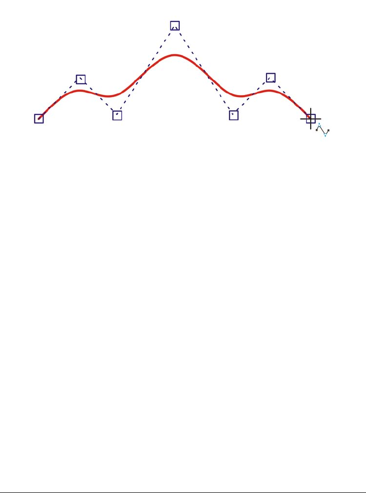
Working with lines, outlines, and brushstrokes 135
if you want to create cusps or straight lines within the B-spline. You can edit completed
B-splines by using the control points.
The path of a B-spline curve is determined by the control points you set.
Some lines have nodes and control points that you can manipulate to shape the lines as
you draw. For information about node types, see “Working with curve objects” on
page 191.
Corel DESIGNER provides preset lines that let you create thick strokes in a variety of
shapes. After you draw a preset line, you can apply a fill to it. For information about
applying fills, see “Filling objects” on page 361.
When drawing lines using the curve tools, you can hide the bounding box that displays
around the lines once they are drawn. The curve tools include: the Linear Pattern tools,
the Freehand tool, the 2-point line tool, the Bézier curve tool, the Pen tool, the
Multi-point line tool, the B-spline tool, and the 3-point curve tool.
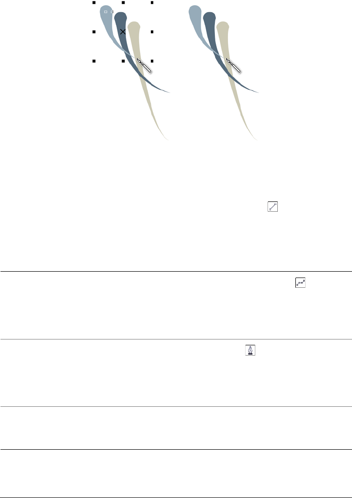
136 Corel DESIGNER X6 User Guide
You can hide the bounding box to enhance the fluidity of drawing lines in
quick succession.
To draw a straight line
1Click the Curve tools button, and click the 2-point line tool .
2Point to where you want to start the line, and drag to draw the line.
As you drag, the length and angle of the segment appear in the status bar.
You can also
Draw a line by using the Multi-point line
tool
Click the Multi-point line tool . Click
where you want to start the line, and click
where you want to end the first line
segment. Click to add additional segments.
Double-click to end the line.
Draw a line by using the Pen tool Click the Pen tool . Click where you want
to start the line segment, and click where
you want to end the first line segment. Click
to add additional segments. Double-click to
end the line.
Add a line segment to a selected line With the 2-point line tool, point to the end
node of a selected line, and drag to draw the
line.
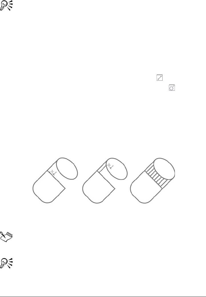
Working with lines, outlines, and brushstrokes 137
You can constrain a two-point line to a straight vertical or horizontal line by
holding down Ctrl while you drag. You can change the angle of this line by
clicking To o l s Options, clicking Edit in the Wor ks p ac e list of categories,
and changing the value in the Constrain angle box.
You can use snapping to specify the start points and endpoints of lines. For
information, see “Working with precision” on page 101.
To draw a perpendicular line
1Click the Curve tools button, and click the 2-point line tool .
2On the property bar, click the Perpendicular 2-point line button .
3Click the edge of an object, and drag to where you want the line to end.
If you want to draw a line that is perpendicular to two objects, drag to the edge of
the second object, and release the mouse button when the perpendicular snap point
appears.
To extend the line beyond the second object, hold down Ctrl when the
perpendicular snap point appears, and drag to where you want the line to end.
Drawing a perpendicular line
This procedure cannot be used for drawing a line that is perpendicular to the
baseline of a text object.
You can also drag from an existing curve to draw a perpendicular line.
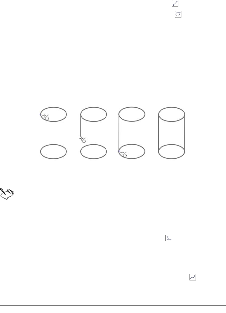
138 Corel DESIGNER X6 User Guide
To draw a tangent line
1Click the Curve tools button, and click the 2-point line tool .
2On the property bar, click the Ta n g e n t i a l 2 - p o i n t line button .
3Click the edge of a curved segment in an object, and drag to where you want the
tangent line to end.
If you want to draw a line that is tangent to two objects, drag to the edge of the
second object, and release the mouse button when the tangent snap point appears.
When the quadrant snap point coincides with tangent snap point, the quadrant
snap point appears.
To extend the line beyond the second object, hold down Ctrl when the tangent
snap point appears, and drag to where you want the line to end.
Drawing tangent lines
The Tangential 2-point line mode can be used for drawing the sides of the
cylinder.
To draw a curved line
1Click the Curve tools button, and click the Freehand tool .
2Point to where you want to start the curve, and drag to draw the line.
You can also
Draw a curved line by using the Multi-point
line tool
Click the Multi-point line tool . Point to
where you want to start the curve, and drag
across the drawing page. Double-click to
finish the curve.
Working with lines, outlines, and brushstrokes 139
You can erase a portion of a freehand curve by holding down Shift and
dragging backward over the line before releasing the mouse button.
You can close an open curve object by clicking Arrange Join curves. The
distance between the endpoints of the open curve should not exceed the Gap
tolerance value in the Join curves docker.
To draw a curved line by specifying width and height
1Click the Curve tools button, and click the 3-point curve tool .
2Click where you want to start the curve, and drag to where you want the curve to
end.
The start and end positions appear in the status bar.
3Release the mouse button, and click where you want the apex of the curve to be.
As you position the apex, the length of the segment appears in the status bar.
To draw a B-spline
1Click the Curve tools button, and click the B-spline tool .
2Click where you want to start the line.
Draw a curved line by using the Bézier
curve tool
Click the Bézier curve tool . Click where
you want to place the first node, and drag
the control point in the direction you want
the curve to bend. Release the mouse button.
Point to where you want to place the next
node, and drag the control point to create
the curve you want. Double-click to finish
the curve. The length of the line appears in
the status bar as you drag.
Draw a curved line by using the Pen tool Click the Pen tool . Click where you want
to place the first node, and drag the control
handle to where you want to place the next
node. Release the mouse button, and drag
the control handle to create the curve you
want. Double-click to finish the curve.
You can also
140 Corel DESIGNER X6 User Guide
3Click to set as many control points as you need to shape your line.
Control points float by default, but you can clamp control points to the line by
pressing V while clicking.
4Double-click to finish the line.
Pressing Esc cancels the line instead of finishing it.
If you add to a B-spline by selecting the first or last control point, the clamped
control point automatically changes to a floating control point as you draw the
new portion of the line.
You can change whether a control point is floating or clamped by holding
down V and clicking a control point with the Shape tool.
You can also
Reshape the line by using control points Select the line using the Shape tool , and
reposition the control points to reshape the
line.
Float a control point Select the line using the Shape tool , click
a clamped control point, and click the Float
control point button on the property
bar.
Clamp a control point Select the line using the Shape tool , click
a floating control point, and click the Clamp
control point button on the property
bar.
Add a control point Select the line using the Shape tool , and
double-click along a control line.
Delete a control point Select the line using the Shape tool , and
double-click the control point that you want
to delete.
Select multiple control points Select the line using the Shape tool , and
hold down Shift while you click the control
points that you want to select.

Working with lines, outlines, and brushstrokes 141
You can also add control points while you draw a B-spline by pressing
Spacebar instead of clicking.
By choosing Arrange Convert to curves, you can convert a B-spline line to
curves and then reshape it by using nodes. After a line has been converted, you
can no longer edit it by using B-spline control points.
To draw a preset line
1Click the Linear pattern tools button, and click the Linear pattern preset
tool .
2Choose a preset line shape from the Preset stroke list box.
3Drag until the line is the shape you want.
If you want to adjust the line width, type a value in the Stroke width box on the
property bar.
To hide the bounding box when using curve tools
1In the toolbox, click one of the following curve tools:
• Linear pattern tools
• Freehand
• 2-point line
• Bézier curve
• Pen
• B-spline
• Multi-point line
• 3-point curve
2Click the Bounding box button on the property bar.
When you hide the bounding box while working with one curve tool, the
bounding box remains hidden for all curve tools. For example, if you hide the
bounding box when using the Freehand tool, it remains hidden when you
switch to the Bézier curve tool.
You can also hide the bounding box when drawing with the curve tools by
clicking To o l s Options. In the Wo rk spa ce list of categories, click Display,
and enable the Hide bounding box for curve tools check box.
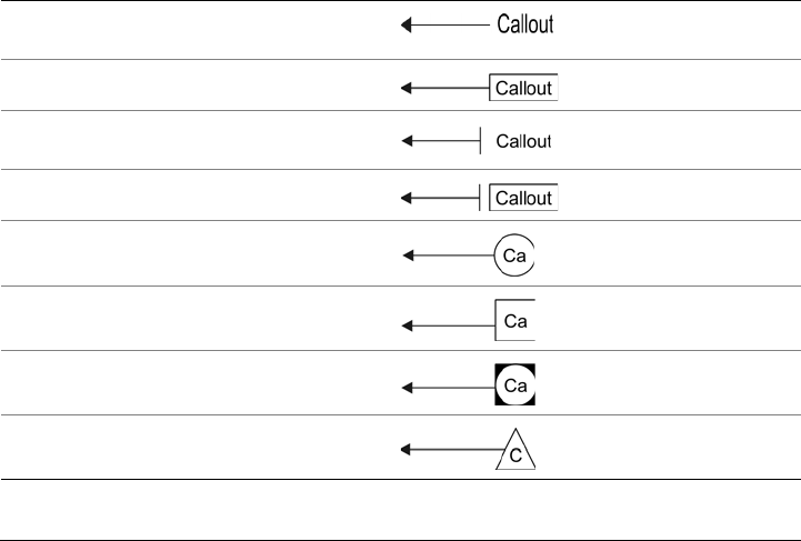
142 Corel DESIGNER X6 User Guide
Closing multiple line segments
The Arrange Join curves command lets you create a closed object from line segments
by selecting which lines you want to connect and the shape of the connecting line.
You can connect lines by using the closest nodes between lines. The connecting line can
be either straight or curved. You can also connect lines by using their start nodes and
end nodes. The end node of the first selected line connects directly with the start node
of the closest selected line. The connected lines will have the properties of the first line
selected. For more information about closing multiple line segments, see “To join
curves” on page 193.
Drawing callouts
You can draw callouts, which are lines with text that point to and identify objects in a
drawing. You can choose from a variety of line ends, including arrowheads and other
styles. Callouts can have one, two, or three line segments, or “legs,” between the line
end and the text.
You can use different shapes for the callout text within a drawing.
Callout shape Example
None
Box
Line (side bar)
Box and line
Circle
Square
Circle and square
Tr i a n g l e
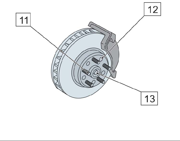
Working with lines, outlines, and brushstrokes 143
You can enhance callouts in several ways. For instance, you can change the line width
and color, and you can adjust the gap between the line and the text.
In addition to typing text, you can insert text from the Clipboard or from object
properties, or you can add a value and increase it in increments as you add more callouts.
For more information about object properties, see “Working with object data” on
page 319.
You can link a callout to its source object by snapping the callout arrowhead to a snap
point. Linked callouts, also known as “sticky callouts,” are attached to the source objects
similarly to connector lines. When you move the source object, the linked callout moves
with it. You can specify how linked callouts move with the object. One option is to
adjust the length of the leader line, leaving the callout text in place. The other option
is to move both the leader line and callout text, preserving the appearance of the callout
group. You can break the link between a callout and its source object at any time.
You can also add a halo behind the callout. A halo is a mask behind the leader line and
text that makes the callout easier to see when it is on top of another object. Usually, the
halo is the same color as the page, although you can choose any color you like.
White halos are applied to the callouts to make them stand out against the
underlying objects.
Callouts are added as linked groups. You can break the callout apart if necessary.
144 Corel DESIGNER X6 User Guide
You can change the default properties of callouts, such as callout style, callout gap, and
halo justification, from the Object styles docker (Window Object styles). For more
information, see “To edit default object properties” on page 576.
To draw a callout
1Click the Callout tools button, and click one of the following tools:
• 1-leg callout
• 2-leg callout
• 3-leg callout
2Click where you want to place the arrowhead and drag to where you want to end
the first line segment.
3Click to end each line segment.
4Add the callout text.
To add text to a callout
1Click the Callout tools button, and click the Text source button .
2Enable one of the following options:
• Interactive — lets you type the text at the end of the callout line
• Clipboard — pastes text from the Clipboard to the callout
• Object property — adds an object property that you choose, such as the
object name, to the callout. For more information, see “To draw a callout that
shows object properties” on page 146.
• Increment — adds a numeric value to the callout. The value is increased in
increments as you continue to add callouts, and you can specify the start value
and the increment amount. The increment values that you set apply only to the
active drawing.
You can also
Change the callout end Select the callout line, and choose a style
from the Start arrowhead list box on the
property bar.
Change the line style Choose a style from the Line style list box
on the property bar.
Change the distance between the leader line
and the callout text
Type a value in the Gap box on the property
bar.
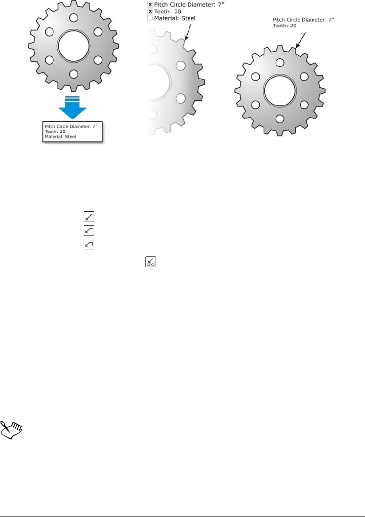
Working with lines, outlines, and brushstrokes 145
If properties are associated with an object, you can show them in callouts.
To draw a linked callout
1Click the Callout tools button, and click one of the following tools:
• 1-leg callout
• 2-leg callout
• 3-leg callout
2Click the Link callout button on the property bar, and choose one of the
following options:
• Change leader line — adjusts the length of the leader line, leaving the callout
text in place
• Move linked callout — moves both the leader line and callout text with the
object
3Point to where you want to place the arrowhead on the object, click when a gravity
source (snap point) appears, and drag to where you want to end the first line
segment.
4Click to end each line segment.
5Add the callout text.
Links between callouts and objects are not maintained when a drawing is saved
to an earlier version of Corel DESIGNER.
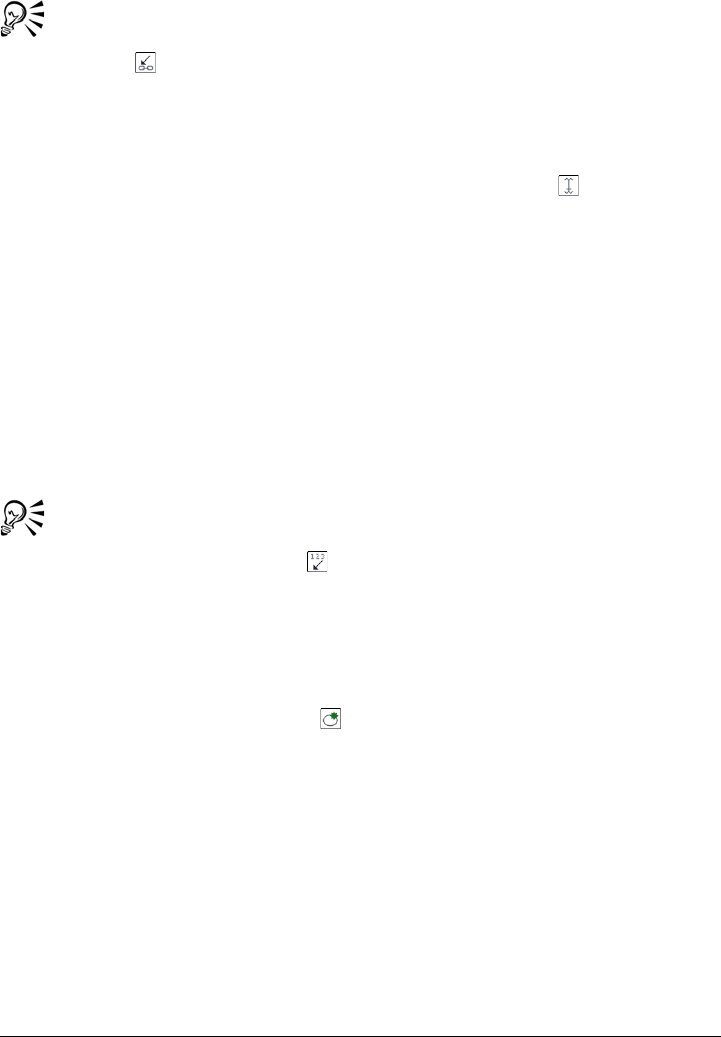
146 Corel DESIGNER X6 User Guide
To break the link between the callout and the object, click the Link callout
button on the property bar, and choose Break callout link. You can also
right-click the callout and choose Break callout link from the context menu.
To draw a callout that shows object properties
1Click the Callout tools button, and click the Text source tool .
2Enable the Object property option.
3Using a callout tool, draw a callout.
4In the Callout data dialog box, enable any of the following check boxes:
• Include field name — includes the field name (such as name or cost) in the
callout text
• Keep updated — automatically updates the callout text when the object data is
modified. This option is available only for linked callouts.
• Apply as default — sets the current settings in the dialog box as the defaults for
new callouts. The dialog box will not be shown when you draw other callouts
that include object data.
You can change how object data is displayed in a callout by clicking the
Callout object data button on the property bar and modifying the settings
you want.
To add a halo to a callout
1Using the Pick tool, select a callout.
2Click the Halo properties button on the property bar.
3Enable the Halo options check box.
4Adjust any of the following settings:
• Width — lets you specify the width of the halo on each side of the line
• Color — lets you access a color palette to change the color of the halo, or use the
color of the page
• Opacity — lets you control the transparency of the halo and the visibility of
objects underneath the halo by specifying a percentage value (with values less
than 100 allowing visibility)
• Justification — lets you specify the position of the halo in relation to the callout
line
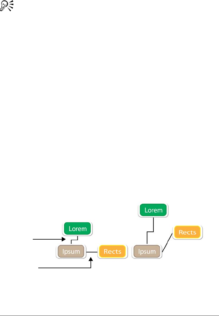
Working with lines, outlines, and brushstrokes 147
To remove a halo from a callout, select the callout, click the Halo properties
button, and disable the Halo options check box.
To break a callout apart
• Right-click the callout, and click Break callout apart.
Drawing connector lines
You can draw connector lines, also known as “flow lines,” in flowcharts and wiring
diagrams to link shapes and demonstrate how different elements in the drawing are
connected. After you attach a connector line to an object, it remains attached to the
object even when you move it. You can also leave an end of a connector line unattached
to any object, and you can add arrowheads to connector lines to demonstrate the flow
direction. For information about drawing flowchart shapes, see “Drawing predefined
shapes” on page 183.
There are several types of connector lines that you can draw. In addition to drawing
straight lines, you can draw right-angle connector lines and automatically create right
angles as you draw. You can choose between the Right-angle connector tool, which
draws a right angle with a sharp corner, and the Right-angle round connector tool,
which draws a rounded corner. You can also draw curved connector lines by using either
the B-spline connector tool or the Bézier curve connector tool.
Examples of connector lines
Connector lines are attached to objects by anchor points. By default, each object has
four anchor points, located on the top, bottom, left, and right sides of the object. Each
Right-angle
connector line
Straight
connector line
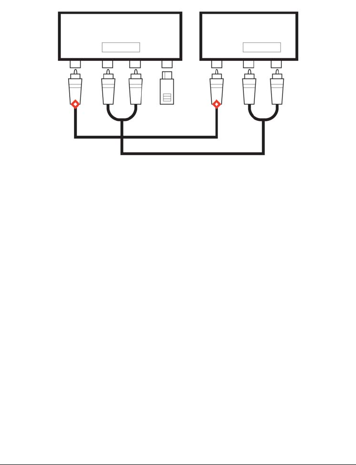
148 Corel DESIGNER X6 User Guide
anchor point appears as a small red diamond on the object. You can move an anchor
point along the edge of an object, or you can move an anchor point to any area inside
or outside the object. You can also add an anchor point to an object.
Anchor points appear as small red diamonds.
When you move an object in a drawing, the connector line will snap to the nearest
available anchor point. When you add an anchor point to an object, it is not available
as a snapping point for connector lines. However, you can set a property on the anchor
point to make it available as a snapping point.
You can set an object to repel right-angle, round right-angle, and B-spline connector
lines. If the object is in a connector line route, the connector line flows around it. If there
is no route for the connector line to follow without intersecting the object, it flows
through the object. Straight-line and Bézier-curve connector lines cannot flow around
objects.
You can add halos to connector lines. A halo is a mask behind the connector line that
makes the line easier to see when it is on top of another object. Usually, the halo is the
same color as the page, although you can choose any color you like. Halos also let you
modify a connector line without requiring extra node editing.
You can also convert connector lines to curves. When you convert a connector line to a
curve, any attached text label changes to an artistic text object.
Working with lines, outlines, and brushstrokes 149
To draw a straight connector line
1Click the Connector tools button, and click the Straight-line connector tool .
2Click where you want to start the line and drag to where you want to end the line.
After you snap a connector line to an anchor point on an object, the connector
line always snaps to that anchor point, even if you move the object around in
the drawing. To ensure that the line connects to the closest available anchor
point when you move the object, release the mouse button to end the connector
line inside the object when drawing the line.
To change the direction of a connector line
1Click the Connector tools button, and click the Edit anchor tool .
2Click the anchor point from which you want to change the connector line direction.
3On the property bar, click the Adjust anchor direction button .
4In the Anchor direction box, type one of the following values:
• 0 — directs the connector line to the right
• 90 — directs the connector line straight up
• 180 — directs the connector line to the left
• 270 — directs the connector line straight down
You can also
Draw a right-angle connector line Click the Connector tools button, and click
the Right-angle connector tool or the
Right-angle round connector tool .
Click where you want to start the line and
drag to where you want to end the line.
Draw a curved connector line Click the Connector tools button, and click
the B-spline connector tool or the
Bézier curve connector tool . Click
where you want to start the line and drag to
where you want to end the line. To change
the shape of the line, reposition the control
points as needed.
150 Corel DESIGNER X6 User Guide
You can change the direction only of right-angle and Bézier-curve connector
lines.
To add an anchor point to an object
1Click the Connector tools button, and click the Edit anchor tool .
2Double-click anywhere on the object to add an anchor point.
By default, anchor points that you add to an object are not available as snap
points for a connector line when the object is moved around in the drawing. To
make an anchor point available as a snap point, select it with the Edit anchor
tool, and click the Auto anchor button on the property bar.
By default, the position of the anchor point is calculated relative to the page.
You can set the anchor point position relative to the object that it is attached
to, which is useful if you want to set anchor points in the same relative position
in multiple objects. To set the anchor point position relative to the object,
select the anchor point with the Edit anchor tool . On the property bar,
click the Relative to object button , and type the coordinates in the Anchor
position box.
To move or delete an anchor point
To set a connector line to flow around objects
1Using the Pick tool , select the object to which the connector line is attached.
2Click Window Property manager.
3In the Property manager docker, click the Summary button.
To Do the following
Move the anchor point anywhere along the
perimeter of an object
Drag the anchor point to another point on
the perimeter.
Move the anchor point to the middle of an
object
Drag the anchor point to any point inside
the object.
Delete an anchor point On the property bar, click the Delete
anchor button .
Working with lines, outlines, and brushstrokes 151
4Enable the Wrap connector line check box.
To convert a connector line to a curve
1Select the connector line and the objects it is attached to.
2Right-click, and click Convert to curves.
You can also convert a curve or a shape, such as a rectangle or an ellipse, to a
connector line by clicking Arrange Convert to connector.
To add a text label to a connector line
1Click the Connector tools button, and click a connector tool.
2Double-click the connector line.
A text cursor appears.
3Ty p e t h e t e x t .
As you move the connector line, the text label remains attached to it.
To add a halo to a connector line
1Using the Pick tool , select the connector line.
2On the property bar, click the Halo properties button .
3Enable the Halo options check box.
4Adjust any of the following settings:
• Width — lets you specify the width of the halo on each side of the line
• Color — lets you access a color palette to change the color of the halo, or use the
color of the page
• Opacity — lets you control the transparency of the halo and the visibility of
objects underneath the halo by specifying a percentage value (with values less
than 100 allowing visibility)
To remove a halo from a line, select the line, click the Halo properties
button , and disable the Halo options check box.
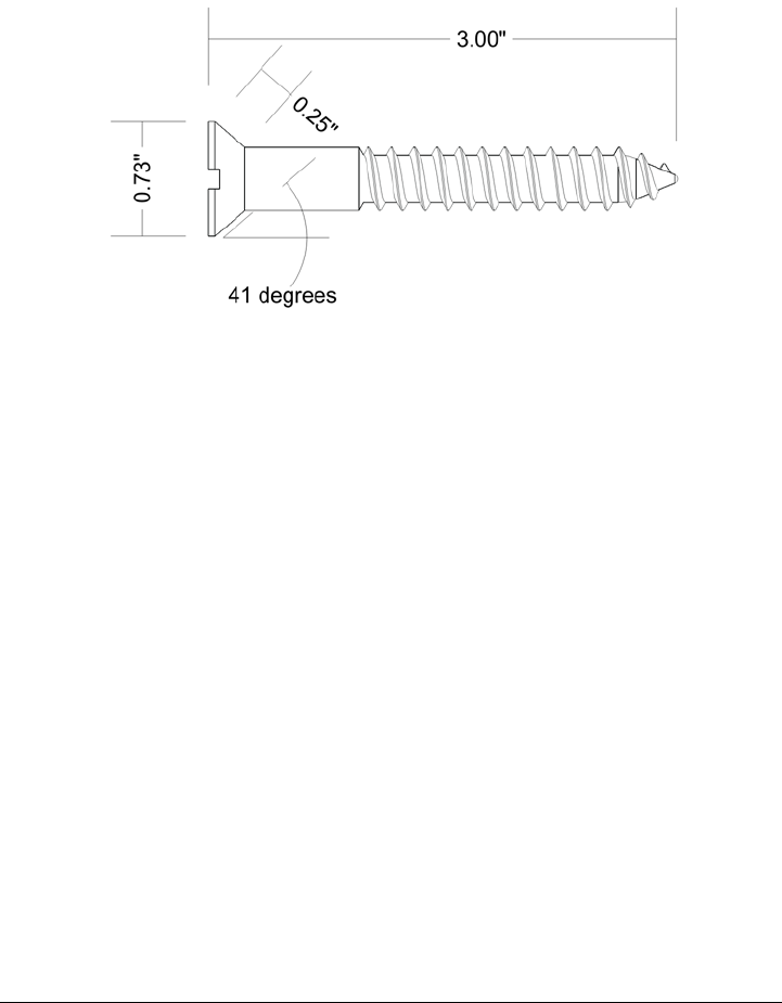
152 Corel DESIGNER X6 User Guide
Drawing dimension lines
You can draw dimension lines to indicate the measurements of objects in a drawing,
such as length, width, height, depth, and distance.
Dimension lines indicate the measurements of objects in a drawing.
You can add several types of dimension lines:
• Vertical or horizontal dimension lines — measure the vertical (y-axis) or horizontal
(x-axis) distance between any two nodes.
• Parallel dimension lines — measure the actual distance between two nodes.
• Angular dimension lines — measure angles.
• Segment dimension lines — measure the linear distance between the end nodes of a
segment, or the linear distance between the two most distant nodes in multiple
segments. Segment dimension lines can also measure selected successive segments.
• Radial or diametric dimension lines — measure the radius or diameter of a circle or
a partial circle.
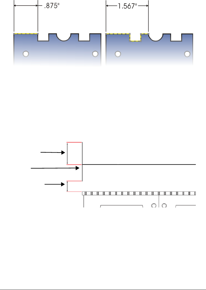
Working with lines, outlines, and brushstrokes 153
You can measure the distance between the end nodes of a segment (left) or
between the two most distant nodes in multiple segments (right).
You can set how dimension text and lines are displayed. For example, you can choose
the unit of measurement, specify the position and font of the dimension units, and add
a prefix or suffix to dimension text. You can also customize the extension lines on which
dimension lines rest. You can specify the distance between the extension lines and the
object that is measured, and the length of the extension overhang. Extension overhang
is the portion of the extension line that falls beyond the dimension arrows.
By default, dimension text is dynamic. If you resize the object to which a dimension line
is attached, the dimension text is updated automatically to display the new size.
However, you can make the dimension text static, if necessary.
When a dimension line is so small that its arrowheads overlap, the application
automatically places them outside the leader lines.
Distance from object
Extension overhang
Extension line
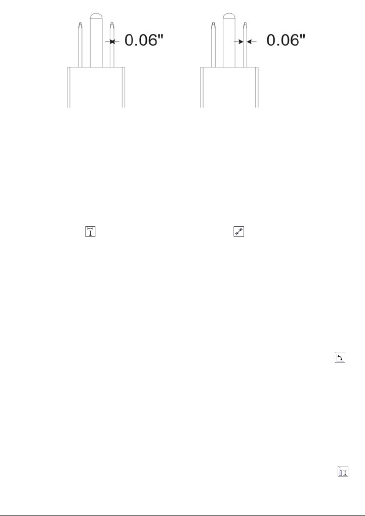
154 Corel DESIGNER X6 User Guide
Arrowheads are reversed when a dimension line is too small.
For more information about formatting lines, see “Formatting lines and outlines” on
page 157.
To draw a vertical, horizontal, or parallel dimension line
1Click the Dimension tools button, and click the Horizontal or vertical
dimension tool or the Parallel dimension tool .
2Click to place the starting point, and drag to where you want to place the endpoint
of the dimension line.
3Move the pointer to position the dimension line, and click to place the dimension
text.
By default, the dimension text is centered on the dimension line.
To draw an angular dimension line
1Click the Dimension tools button, and click the Angular dimension tool .
2Click where you want the two lines that measure the angle to intersect, and drag to
where you want the first line to end.
3Click where you want the second line to end.
4Click where you want the angle label to appear.
To draw a segment dimension line
1Click the Dimension tools button, and click the Segment dimension tool .
2Click the segment that you want to measure.
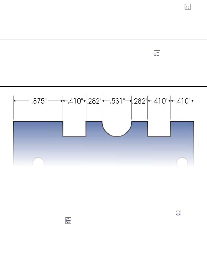
Working with lines, outlines, and brushstrokes 155
3Move the pointer to where you want to position the dimension line, and click
where you want to place the dimension text.
Segment dimension lines can be applied automatically to selected successive
segments.
To draw a radial or diametric dimension line
1Click the Dimension tools button, and click the Radial dimension or
Diametric dimension tool.
2Click a circle or an arc, and drag to where you want the line to change direction.
You can hold down the constrain key while dragging to constrain the leader line to
the current constrain angle.
3Move the pointer, and then click to place the dimension text.
You can also
Measure the distance between the two most
distant nodes in multiple segments
Using the Segment dimension tool ,
marquee select the segments, move the
pointer to position the dimension line, and
click where you want to place the dimension
text.
Measure successive segments automatically Click the Automatic successive
dimensioning button on the property
bar, and marquee select the segments that
you want to measure. Move the pointer to
position the dimension line, and click where
you want to place the dimension text.
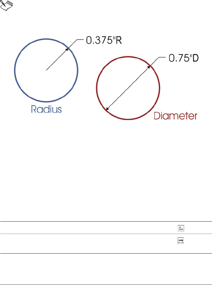
156 Corel DESIGNER X6 User Guide
If you want to add a symbol to the dimension text, choose a symbol from the
Dimension symbol list box on the property bar.
If you transform a circle to an ellipse after applying a radial or diametric
dimension line, the dimension measurement does not appear. When you
transform the ellipse back to a circle, the correct measurement is displayed.
Examples of radial and diametric dimension lines
To set the display of dimension units
1Select a dimension line.
2On the property bar, choose options from the following list boxes:
• Dimension style — lets you choose fractional, decimal, or standard dimension
units
• Dimension precision — lets you choose a level of precision for the
measurements
• Dimension units — lets you choose the unit of measurement
You can also
Hide dimension units Click the Display units button .
Specify the position of dimension units Click the Text position button on the
property bar, and choose a text position.

Working with lines, outlines, and brushstrokes 157
To customize extension lines
1Select a dimension line.
2On the property bar, click the Extension line options button .
3To specify the distance between the extension lines and the object, enable the
Distance from object check box, and type a value in the Distance box.
4To specify the length of the extension overhang, enable the Extension overhang
check box, and type a value in the Distance box.
Formatting lines and outlines
You can change the appearance of both lines and outlines. For example, you can specify
their color, width, style, corner shape, and cap style. You can also remove a line or
outline, and you can create your own line or outline style.
Change the point size and font of dimension
units
Select the dimension text using the Pick
tool . On the property bar, choose a font
style from the Font list box, and type a
value in the Font size box.
Specify a prefix or suffix for dimension text Type a prefix or suffix in the Prefix or Suffix
box on the property bar.
Hide or show a leading zero with a
dimension value
Click the Show leading zero button on
the property bar.
The leading zero appears in dimension lines
by default.
Make dimension text static Click the Dynamic dimensioning
button on the property bar.
Most dimension line controls on the property
bar become unavailable. If you change the
size of the object to which the line is
attached, the dimension line text is not
updated.
You can also
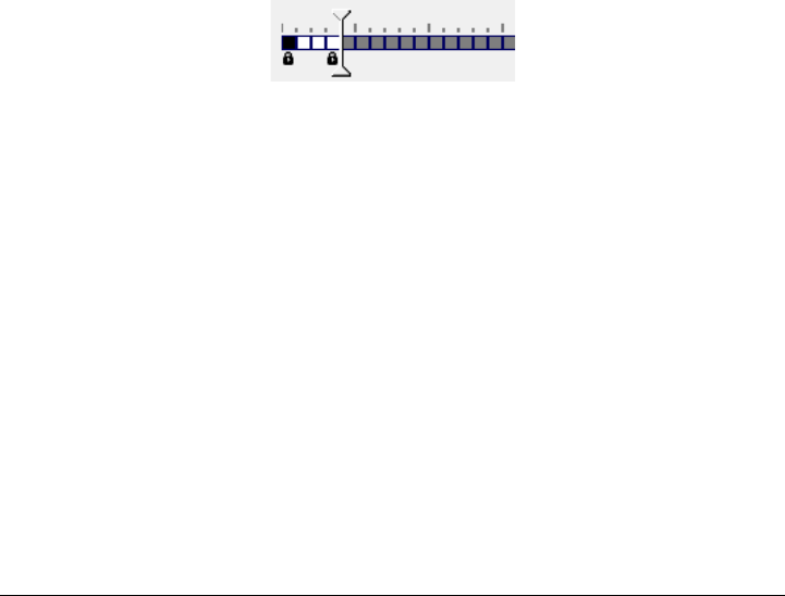
158 Corel DESIGNER X6 User Guide
The program also lets you copy the color of an outline to other objects and convert
outlines to objects so that you can fill them. For more information about filling objects,
see “Filling objects” on page 361.
Setting the miter limit for outlines lets you specify at what angle a sharp corner is either
mitered (pointed) or beveled (squared off).
Line styles
You can choose from a variety of line styles. Line styles are organized into two
categories: standard and enhanced.
Standard line styles consist exclusively of dashes and spaces. The dashes and spaces vary
to create different patterns. You can use a preset pattern or create a custom pattern.
Each line style pattern is defined by units. There are fifty units — each of which can be
“on” (filled in) or “off ” (blank) to define a pattern that contains a maximum of ten
dashes or spaces. You can also set the pattern length. When you increase or decrease the
pattern length, the dashes and spaces appear longer or shorter because you are changing
the size of the units to fit the specified pattern length. The line width is not affected if
you change the pattern length.
In the Edit line style dialog box, each box represents a unit that can be filled
in to create a dash, or left blank to create a space. You can move the white slider
to the right to increase the number of units in your pattern.
Enhanced line styles consist of shapes, zigzags, or multiple lines to create diverse
patterns. You can edit an enhanced line style by changing the width of the lines or the
width of the overall pattern.
When you apply an enhanced line style to a filled object, the fill is contained within the
path of the object, not the outline. For example, if you have an object with a zigzag line
style, the fill does not extend into the points of the zigzag.
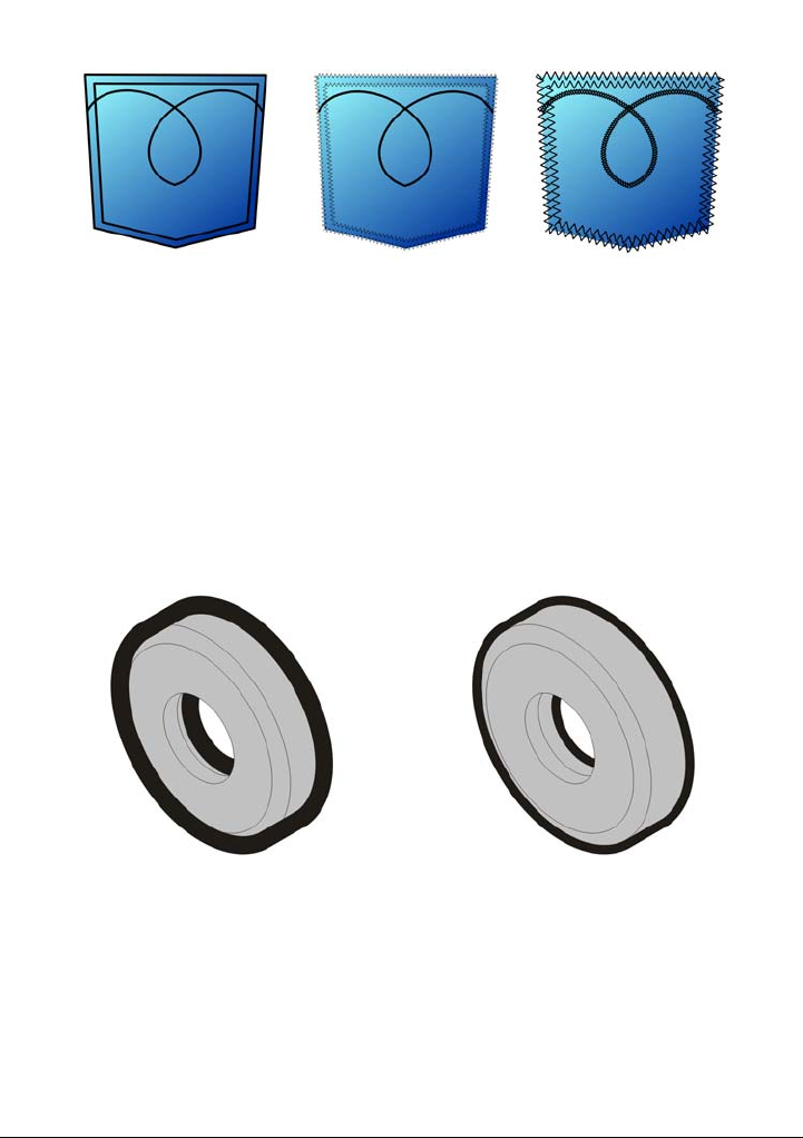
Working with lines, outlines, and brushstrokes 159
These pocket drawings use a standard line style (left), an enhanced line style
with low pattern-width settings (center), and an enhanced line style with
higher pattern-width settings (right). The fill is always contained within the
object’s path, not the object’s outline.
The outline created by a standard or enhanced line style can appear in front of or behind
a fill. For example, you may want an outline to appear behind a fill to line up the outline
with the outer edge of the fill.
In the drawing on the left, the outline is in front of the fill. Because the outline
width is centered on the object’s path, the outline covers part of the object’s fill.
In the drawing on the right, the outline width is the same, but the outline has
been moved behind the fill and therefore lines up with the outer edge of the
object.
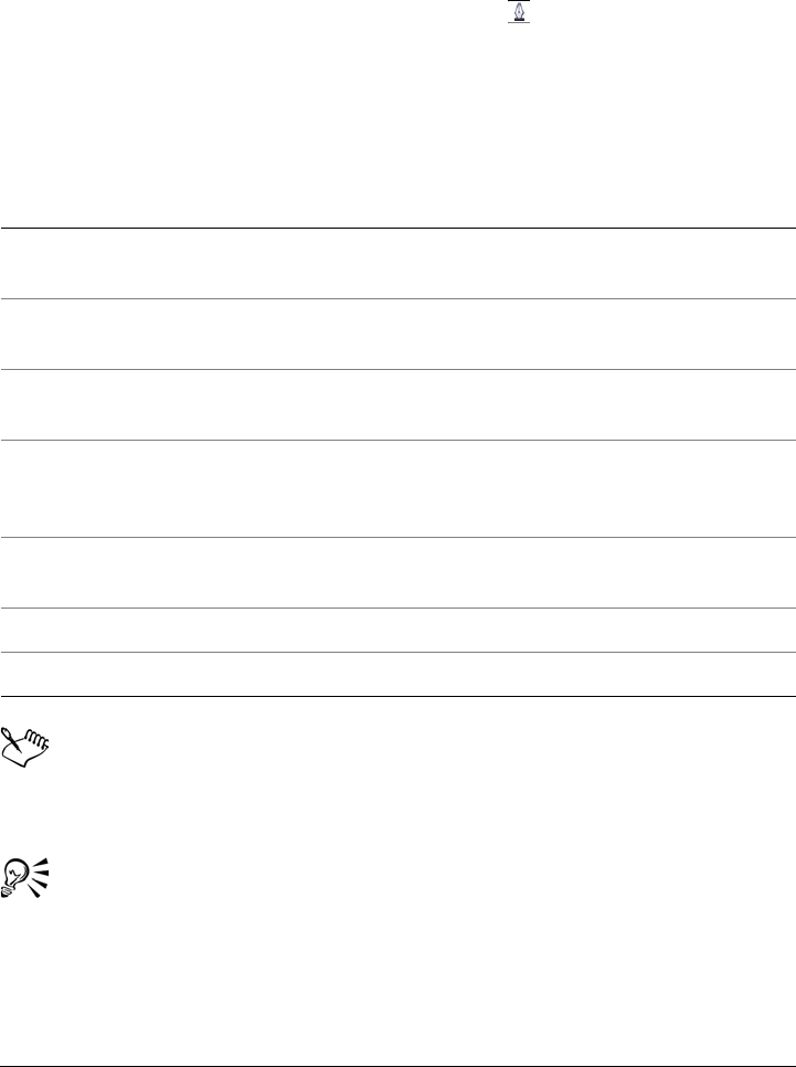
160 Corel DESIGNER X6 User Guide
To specify line and outline settings
1Select an object.
2On the property bar, click the Outline pen button .
3In the Pattern style area of the Outline pen dialog box, enable the Standard or
Enhanced option.
4Choose a line style from the Pattern list box.
5Specify the settings you want.
If the pattern Width value is too low, the pattern might not appear as
expected. To view the pattern on your object, try increasing the pattern Width
value and decreasing the outline Width value.
You can also specify line settings from the property bar or the Outline area of
the Property manager docker.
You can also change the color of a line or outline by right-clicking a color
swatch on the color palette.
To Do the following
Change the line or outline color In the Outline area, choose a color from the
color picker.
Change the line or outline width In the Outline area, type a value in the
Width box.
Change the pattern length of a standard
pattern
In the Pattern style area, type a value in the
Length box.
Change the width of an enhanced pattern In the Pattern style area, type a value in the
Width box. The pattern width value must
be higher than the outline width value.
Automatically scale the line or outline if an
object is resized
Enable the Scale with image check box.
Position the outline beneath the fill Enable the Behind fill check box.
Set the miter limit Type a value in the Miter limit box

Working with lines, outlines, and brushstrokes 161
To edit a standard line style
1Select an object.
2On the property bar, click the Outline pen button .
3In the Pattern style area, enable the Standard option.
4Choose a line style from the Pattern list box.
5Click Edit style.
6Follow the instructions in the Edit line style dialog box to edit the pattern.
7Click Replace.
To create a standard line style
1Select an object.
2On the property bar, click the Outline pen button .
3In the Pattern style area, enable the Standard option.
4Click Edit style.
5Follow the instructions in the Edit line style dialog box to create a new pattern.
6Click Add to save your new pattern in the Pattern list box.
To copy an outline to another object
1Using the Pick tool , select the object that has the outline to be copied.
2Right-click the object, and drag to the second object.
A blue outline of the first object follows the pointer to the second object.
3Release the mouse button over the second object, and choose Copy outline here.
For more information about copying object properties, see “Copying object
properties, transformations, and effects” on page 253.
To convert an outline to an object
1Select an object.
2Click Arrange Convert outline to object.

162 Corel DESIGNER X6 User Guide
The gear drawing on the left has a gray fill and a blue outline. By converting
the outline to an object, you can separate the new object (center) from the old
filled shape (right).
To remove an outline from an object
1Select an object.
2On the property bar, choose None from the Outline width list box.
You can also remove an object’s outline by selecting the object and
right-clicking the No color swatch on the color palette.
Adding arrowheads to lines and curves
Arrowheads let you enhance the starting points and endpoints of lines and curves. You
can specify the attributes of an arrowhead with precision. For example, you can define
the exact size of an arrowhead as well as offset or rotate the arrowhead by a precise
amount. You can also flip arrowheads vertically and horizontally. You can save your
specified attributes as arrowhead presets for later use.
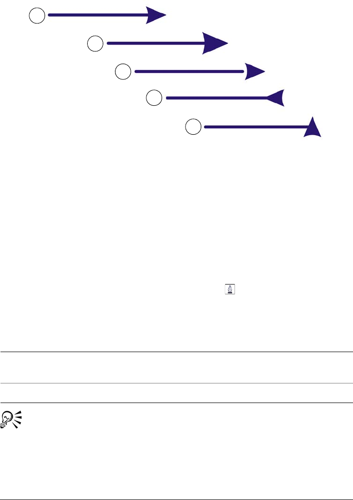
Working with lines, outlines, and brushstrokes 163
Arrowhead in its original form (1), resized (2), with offset of 60% along the
x-axis (3), flipped horizontally (4), and rotated at 90 degrees (5).
You can edit existing arrowhead presets, and you can create an arrowhead preset based
on an existing one. You can also create an arrowhead preset based on an object such as
a curve or a closed shape. When you no longer need an arrowhead preset, you can delete
it.
To add an arrowhead
1Select a line or curve.
2On the property bar, click the Outline pen button .
3In the Arrowheads area of the dialog box, open the Start arrowhead or End
arrowhead picker, and click a shape.
You can also add an arrowhead by using the Start arrowhead or End
arrowhead picker on the property bar.
You can also
Switch arrowheads from one end of a line or
curve to another
Click Options, and choose Swap.
Remove an arrowhead from a line or curve Click Options, and choose None.
1
2
3
4
5
164 Corel DESIGNER X6 User Guide
To specify the arrowhead attributes of a line or curve
1Using the Pick tool , select a line or curve that has an arrowhead.
2On the property bar, click the Outline pen button .
If you want the start and end arrowheads to have the same size, offset, rotation
angle, and orientation, enable the Share attributes check box in the Arrowheads
area of the Outline pen dialog box.
3In the Arrowheads area of the Outline pen dialog box, click Options below the
Start arrowhead or End arrowhead picker, and click Attributes.
4In the Arrowhead attributes dialog box, perform any of the tasks in the following
table.
Specifying the attributes of an arrowhead does not change the arrowhead preset
that was applied.
To Do the following
Specify the size of an arrowhead In the Size area, type a value in the Length
or Width box.
If you want to create a nonproportional
arrowhead, disable the Proportional check
box.
Offset an arrowhead In the Offset area, type values in the X and
Y boxes.
Mirror an arrowhead In the Mirror area, enable the Horizontally
or Vertically check box.
Rotate an arrowhead Specify an angle in the Rotation box.
Save custom arrowhead attributes as an
arrowhead preset
Enable the Save as arrowhead preset check
box.
You can access the new arrowhead preset
from the Start arrowhead and End
arrowhead pickers on the property bar.

Working with lines, outlines, and brushstrokes 165
To edit an arrowhead preset
1Using the Pick tool , select an object that has an arrowhead.
2On the property bar, click the Outline pen button .
3In the Arrowheads area of the Outline pen dialog box, click Options, and choose
Edit.
4In the Arrowhead attributes dialog box, specify the attributes you want.
For information about the attributes you can specify, see “To specify the arrowhead
attributes of a line or curve” on page 164.
You can create an arrowhead preset that is based on an existing preset. In the
Arrowheads area of the Outline pen dialog box, click Options, and choose
New. Then, specify the attributes you want in the Arrowhead attributes
dialog box, and type a preset name in the Save arrowhead area.
To delete an arrowhead preset, select the preset from the Start or End
arrowhead picker in the Outline pen dialog box, click Options, and choose
Delete.
To create an arrowhead preset from an object
1Select an object to use as an arrowhead.
2Click To o l s Create Arrowhead.
3In the Create arrowhead dialog box, type a value in the Length box or Width
box.
If you want to create a nonproportional arrowhead, disable the Proportional check
box, and type values in both the Length and Width boxes.
Drawing calligraphic, pressure-sensitive, and preset lines
Corel DESIGNER lets you simulate the effect of a calligraphic pen when you draw lines.
Calligraphic lines vary in thickness according to the direction of the line and the angle
of the pen nib. By default, calligraphic lines appear as closed shapes drawn with a pencil.
You can control the thickness of a calligraphic line by changing the angle of the line that
you draw in relation to a specified calligraphic angle. For example, when the line that
you draw is perpendicular to the calligraphic angle, the line is at the maximum
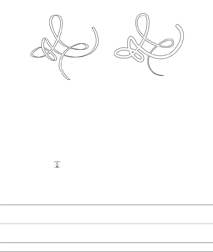
166 Corel DESIGNER X6 User Guide
thickness specified by the pen width. Lines drawn at the calligraphic angle, however,
have little or no thickness.
By using either a mouse or a pressure-sensitive pen and graphics tablet, you can create
pressure-sensitive lines that vary in thickness. Both methods result in lines with curved
edges and varying widths along a path. For information about using a pressure-sensitive
pen on a graphics tablet, see the manufacturer’s instructions.
An image drawn by using two different linear pattern lines: calligraphic lines
(left), and flat preset lines (right).
You can use preset lines to create thick strokes of various shapes.After you draw a
calligraphic or preset line, you can apply a fill to it. For information about applying fills,
see “Filling objects” on page 361.
To draw a calligraphic line
1In the toolbox, click the Linear pattern tools button, and then click the
Calligraphic tool .
2Type a value in the Calligraphic angle box on the property bar.
3Drag until the line is the shape you want.
You can also
Set the width of the line Type a value in the Stroke width box on the
property bar.
Smooth the edges of the line Type a value in the Freehand smoothing
box on the property bar.
Working with lines, outlines, and brushstrokes 167
The width you set is the maximum line width. The angle of the line you draw
in relation to the calligraphic angle determines the line’s actual width.
You can also access calligraphic lines by clicking Effects Linear patterns
and specifying the settings that you want in the Linear patterns docker.
To draw a pressure-sensitive line
1In the toolbox, click the Linear pattern tools button, and then click the Pressure
tool .
If you are using the mouse, press the Up arrow or Down arrow to simulate
changes in pen pressure, which change the width of the line.
2Drag until the line is the shape you want.
The width you set represents the line’s maximum width. The amount of
pressure that you apply determines the line’s actual width.
Apply transformations to line thickness
when scaling
Click the Scale stroke with object
button on the property bar.
Hide the bounding box for drawing Click the Bounding box button on the
property bar.
You can also
Set the width of the line Type a value in the Stroke width box on the
property bar.
Smooth the edges of the line Type a value in the Freehand smoothing
box on the property bar.
Apply transformations to line thickness
when scaling
Click the Scale stroke with object
button on the property bar.
Hide the bounding box for drawing Click the Bounding box button on the
property bar.
You can also
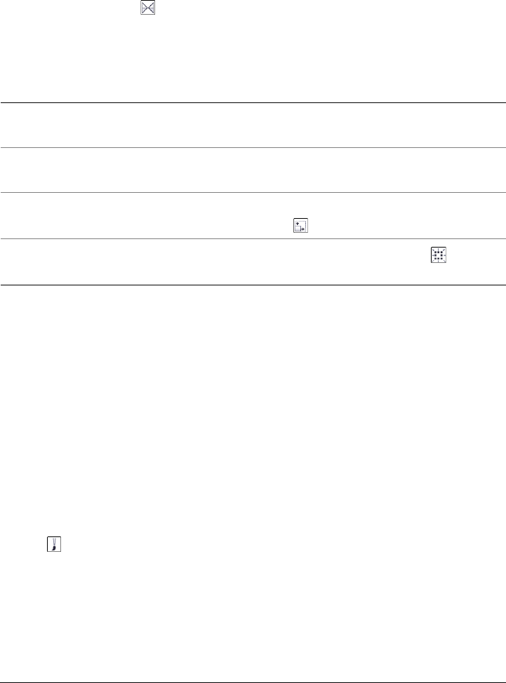
168 Corel DESIGNER X6 User Guide
To draw a preset line
1In the toolbox, click the Linear pattern tools button, and click the Linear
pattern preset tool .
2Choose a line shape from the Preset stroke list box on the property bar.
3Drag until the line is the shape you want.
Applying linear-pattern brushstrokes
Corel DESIGNER lets you apply a variety of preset brushstrokes, ranging from
brushstrokes with arrowheads to brushstrokes that are filled with patterns. When you
draw a preset brushstroke, you can specify some of its attributes. For example, you can
change the width of a brushstroke and specify its smoothness.
You can also create custom brushstrokes by using an object or a group of vector objects.
When you create a custom brushstroke, you can save it as a preset.
To apply a preset brushstroke
1Click the Linear pattern tools button, and click the Linear pattern brush
tool .
2Choose a brush category from the Category list box on the property bar.
3Choose a brushstroke from the Brushstroke list box on the property bar.
4Drag until the stroke is the shape you want.
You can also
Set the width of the line Type a value in the Stroke width box on the
property bar.
Smooth the edges of the line Type a value in the Freehand smoothing
box on the property bar.
Apply transformations to line thickness
when scaling
Click the Scale stroke with object
button on the property bar.
Hide the bounding box for drawing Click the Bounding box button on the
property bar.
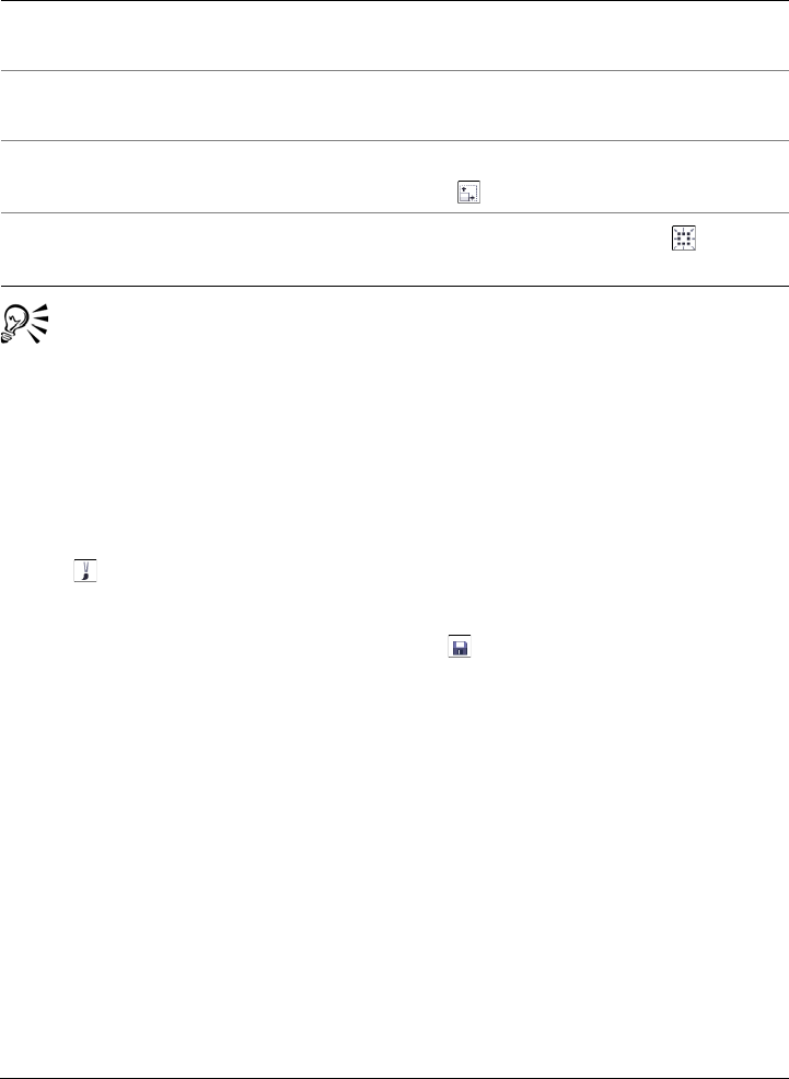
Working with lines, outlines, and brushstrokes 169
If you have access to a brushstroke that is not listed in the Brushstroke list
box, you can apply it by clicking the Browse button on the property bar, and
locating the brushstroke file.
To create a custom brushstroke
1Select an object or a set of grouped objects.
2Click the Linear pattern tools button, and click the Linear pattern brush
tool .
3Click the object or grouped objects.
4Click the Save linear pattern stroke button on the property bar.
5Type a filename for the brushstroke.
6Click Save.
You can also
Set the width of the stroke Type a value in the Stroke width box on the
property bar.
Smooth the edges of the stroke Type a value in the Freehand smoothing
box on the property bar.
Apply transformations to stroke thickness
when scaling
Click the Scale stroke with object
button on the property bar.
Hide the bounding box for drawing Click the Bounding box button on the
property bar.
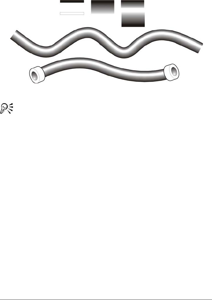
170 Corel DESIGNER X6 User Guide
Example of a custom linear pattern brushstroke
You can also create custom brushstrokes by clicking Window Linear
patterns and specifying the settings that you want in the Linear patterns
docker.
Spraying linear patterns along a line
Corel DESIGNER lets you spray a series of objects along a line. You can spray graphics,
text, or imported bitmaps or symbols.
You can control how a sprayed line appears by adjusting the spacing between objects,
so that they are closer or farther apart from each other. You can also vary the order of
objects in the line. For example, if you are spraying a series of objects that includes a
star, a triangle, and a square, you can change the spray order so that the square appears
first, the triangle second, and the star third. The program also lets you shift the position
of objects in a sprayed line by rotating them along the path, or by offsetting them in
one of four different directions: alternating, left, random, or right. For instance, you can
choose a left offset direction to align the sprayed objects to the left of the path.
You can also create a new spraylist with objects of your own.
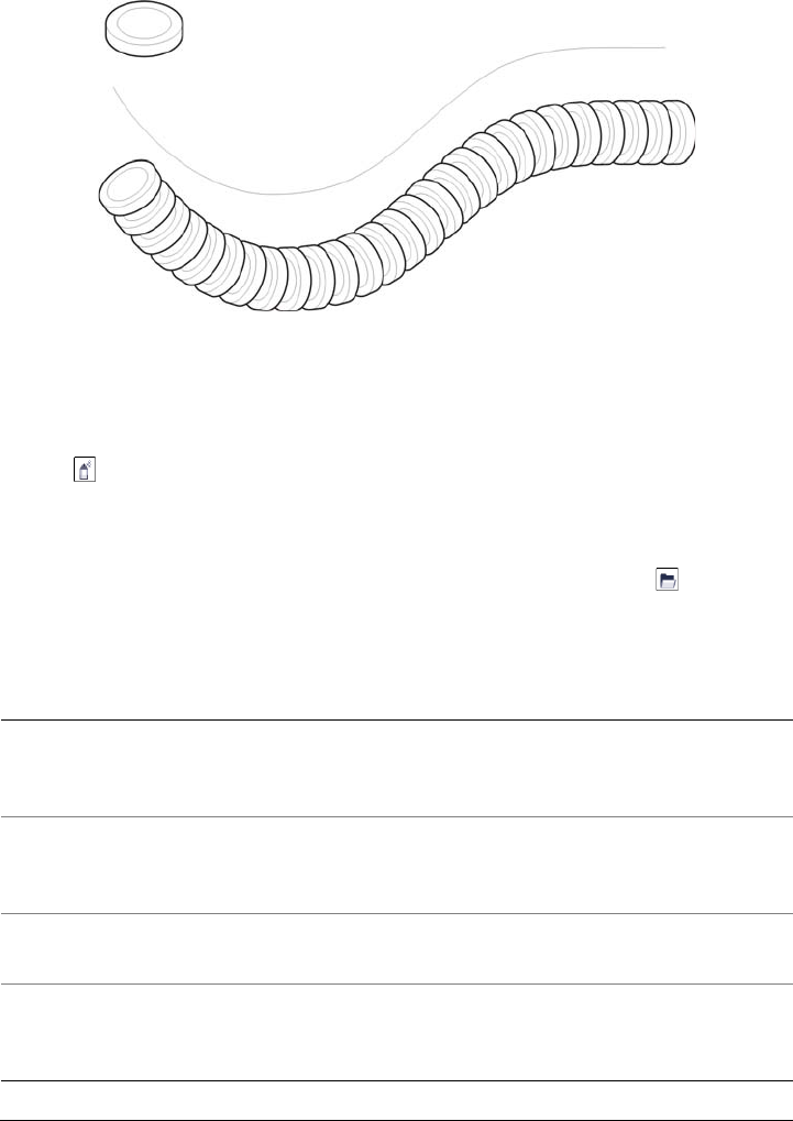
Working with lines, outlines, and brushstrokes 171
The Linear pattern sprayer tool lets you repeat objects along a line.
To spray a line
1Click the Linear pattern tools button, and click the Linear pattern sprayer
tool .
2Choose a spray pattern category from the Category list box on the property bar.
3Choose a spray pattern from the Spray pattern list box on the property bar.
If the spraylist that you want is not listed, click the Browse button on the
property bar and navigate to the folder where the file is located.
4Drag to draw the line.
You can also
Adjust the number of objects sprayed at each
spacing point
Type a number in the upper portion of the
Images per dab and image spacing box on
the property bar.
Adjust the spacing between dabs Type a number in the lower portion of the
Images per dab and image spacing box on
the property bar.
Set the spray order Choose a spray order from the Spray order
list box on the property bar.
Adjust the size of spray objects Type a number in the upper portion of the
Size of sprayed objects box on the property
bar.
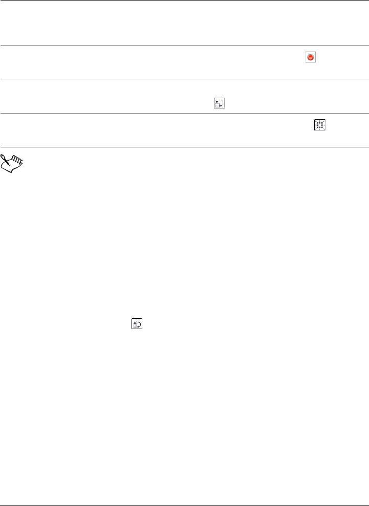
172 Corel DESIGNER X6 User Guide
Increasing the value for the size of the objects to be sprayed along the line
causes objects to become larger as they are distributed along the path.
Spraylists that have more complex objects use more system resources. Lines
that contain complex objects take longer to produce, and these objects increase
the file size. Using symbols for each group in the list can help reduce file size
and the demands on your system. For more information about creating
symbols, see “Working with symbols” on page 277.
To rotate the objects to be sprayed
1Select a spraylist.
2Click the Rotation button on the property bar.
3Type a value between zero and 360 in the Angle of rotation box.
If you want each object in the spraylist to rotate incrementally, enable the
Increment check box, and type a value in the box.
4Enable one of the following options:
• Relative to path — rotates objects in relation to the line
• Relative to page — rotates objects in relation to the page
5Press Enter.
Increase or decrease the size of the objects to
be sprayed as they progress along the line
Type a number in the lower portion of the
Size of sprayed objects box on the property
bar.
Reset a spraylist to its saved settings Click the Reset values button on the
property bar.
Apply transformations to stroke thickness
when scaling
Click the Scale stroke with object
button on the property bar.
Hide the bounding box for drawing Click the Bounding box button on the
property bar.
You can also

Working with lines, outlines, and brushstrokes 173
To offset the objects to be sprayed
1Select a spraylist.
2Click the Offset button on the property bar.
3Enable the Use offset check box to offset objects from the path of the line sprayed.
If you want to adjust the offset distance, type a new value in the Offset box.
4Choose an offset direction from the Direction list box.
If you want to alternate between the left and the right of the line, choose
Alternating.
To create a new spraylist
1Click Effects Linear patterns.
2Select an object, a set of grouped objects, or a symbol.
3Click the Save button in the Linear patterns docker.
4In the Create a new stroke dialog box, enable the Object sprayer option.
5Click OK.
6Type a filename in the File name box.
7Click Save.
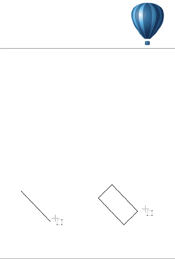
Drawing shapes 175
Drawing shapes
Corel DESIGNER lets you draw basic shapes, which you can modify using special
effects and reshaping tools.
This section contains the following topics:
• Drawing rectangles and squares
• Drawing ellipses, circles, arcs, and wedges
• Drawing polygons and stars
•Drawing grids
• Drawing predefined shapes
• Drawing projected shapes
• Drawing by using shape recognition
Drawing rectangles and squares
Corel DESIGNER lets you draw rectangles and squares. You can draw a rectangle or
square by dragging diagonally with the 2-point rectangle tool or by specifying the
width and height with the 3-point rectangle tool. The 3-point rectangle tool lets you
quickly draw rectangles at an angle.
You can create a 3-point rectangle by first drawing its baseline and then
drawing its height. The resulting rectangle is angled.
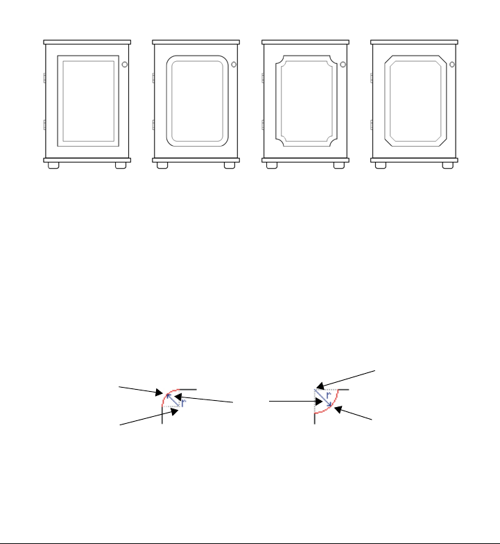
176 Corel DESIGNER X6 User Guide
You can also draw a rectangle or square with rounded, scalloped or chamfered corners.
You can modify each corner individually or apply the changes to all corners. In addition,
you can specify that all corners scale relative to the object. You can also specify the
default corner size for drawing rectangles and squares.
Understanding rounded, scalloped, and chamfered corners
Rounding produces a curved corner, scalloping replaces the corner with an edge that has
a curved notch, and chamfering replaces the corner with a straight edge, also known as
a bevel.
The cabinet doors have different styles applied to the corners. From left to right
you can see standard corners with no changes, filleted corners, scalloped corners,
and chamfered corners.
To draw rectangles or squares with rounded, scalloped, or chamfered corners, you need
to specify the corner size. For rounding or scalloping a corner, the corner size determines
the corner radius. The radius is measured from the curve’s center to its perimeter.
Higher corner size values produce more rounded corners or deeper scalloped corners.
From left to right, you can see the radius of a rounded corner and the radius of
a scalloped corner.
Center
Center
Perimeter
Perimeter
Radius
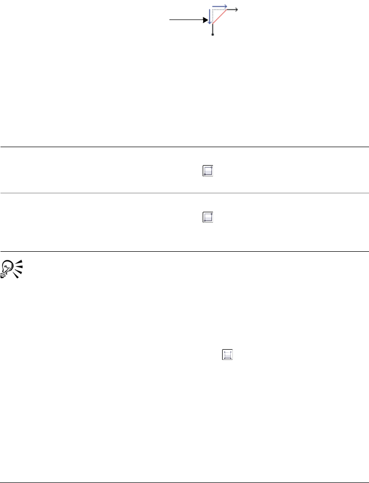
Drawing shapes 177
The size value for chamfering a corner represents the distance from the original corner
to the beginning of the chamfered edge. Higher values produce a longer chamfered
edge.
For more information about modifying the corners of curve objects, such as lines, text,
or bitmaps, see “Filleting, scalloping, and chamfering corners of curve objects” on
page 206.
To draw a rectangle or square by dragging diagonally
You can draw a rectangle from its center outward by holding down Shift as
you drag. You can also draw a square from its center outward by holding down
Shift + Ctrl as you drag.
To draw a 3-point rectangle
1In the toolbox, click the 3-point rectangle tool .
2In the drawing window, point to where you want to start the rectangle, drag to
draw the width, and release the mouse button.
3Move the pointer to draw the height, and click.
To adjust the size of the rectangle, type values in the Object size boxes on the
Tr a n s f o r m toolbar. To open the Tr a n s f o r m toolbar, click View To o l b a r s
Tr a n s f o r m .
To Do the following
Draw a rectangle In the toolbox, click the 2-point rectangle
tool . Drag in the drawing window until
the rectangle is the size you want.
Draw a square In the toolbox, click the 2-point rectangle
tool . Hold down Ctrl, and drag in the
drawing window until the square is the size
you want.
Distance
178 Corel DESIGNER X6 User Guide
To constrain the angle of the baseline to a preset increment, known as constrain
angle, hold down Ctrl as you drag. For information about changing the
constrain angle, see “To constrain an object while drawing or editing” on
page 118.
To draw a rectangle or square with rounded, scalloped, or chamfered
corners
1Click a rectangle or square.
2Click one of the following buttons on the property bar:
• Round corner — produces a curved corner
• Scalloped corner — replaces a corner with an edge that has a curved notch
• Chamfered corner — replaces a corner with a flat edge
3Type values in the Corner radius boxes on the property bar.
4Press Enter.
If you modify the corners of a rectangle or square and save it to a previous
version of Corel DESIGNER, the shape may be converted to curves.
You can also modify the corners of a selected rectangle or square by clicking
the Shape tool , clicking a corner option button on the property bar, and
then dragging a corner node toward the shape’s center. If you want to modify
only one corner, hold down Ctrl as you drag.
To specify the default corner size for drawing rectangles and squares
1Click To o l s Options.
2Double-click To o l b o x from the Work sp ace list of categories.
3Click Rectangle tool.
You can also
Apply the same changes to all corners Click the Edit corners together button
on the property bar.
Disable the scaling of corners relative to the
object
Click the Relative corner scaling button
on the property bar.
Drawing shapes 179
4In the Rectangle corners area, type values in the boxes.
Drawing ellipses, circles, arcs, and wedges
You can draw an ellipse by dragging diagonally or by specifying three points. You can
also draw a circle by specifying three points, or you can specify the center and a point
on the radius.
Another way to create an ellipse is to convert a curve object. The object to be converted
must have a recognizable elliptical shape to be eligible. For instructions, see “To convert
a curve to an ellipse” on page 194.
Drawing an arc or wedge (pie shape) is similar to drawing a circle or an ellipse, except
that you move the line end points around to create the shape.
To draw an ellipse or a circle
•Click the Circle tools or Ellipse tools button, and click the tool that you want to
use.
You can also
Apply the same changes to all corners Click the Edit corners together button .
Disable the scaling of corners relative to the
object
Click the Relative corner scaling
button .
To draw a Do the following
3-point circle Click the 3-point circle tool . Drag to
specify the centerline of the circle, move the
pointer, and click to specify the third point.
Center-point circle Click the Center-point circle tool . Click
where you want to place the center, drag
until the circle is the size you want, and
release the mouse button.
Center-radius circle Click the Center-radius circle tool . In
the Circle dialog box, type a value for the
radius, and click where you want to place the
center point.
180 Corel DESIGNER X6 User Guide
When you draw a circle, holding down the constrain key while dragging
constrains the shape to the current constrain angle. See “Using constrain keys”
on page 118 for more information. Holding down the constrain key while
drawing an ellipse constrains the shape to a circle.
You can draw a two-point or three-point ellipse from its center outward by
holding down the Shift key as you drag (if the constrain key is Ctrl).
To draw an arc or a wedge
•Click the Circle tools or Ellipse tools button, and click the tool that you want to
use.
When you draw an arc, the ellipse or circle must have an outline.
2-point ellipse Click the 2-point ellipse tool . Drag
diagonally until the ellipse is the size you
want, and release the mouse button.
3-point ellipse Click the 3-point ellipse tool . Drag to
specify the centerline of the ellipse, and
release the mouse button. Move the pointer
until the ellipse is the size and shape you
want, and click.
To draw Do the following
An arc Click the Arc button on the property bar.
Drag in the drawing window until the arc is
the shape you want.
A wedge Click the Pie button on the property bar.
Drag in the drawing window until the
wedge is the shape you want.
To draw a Do the following
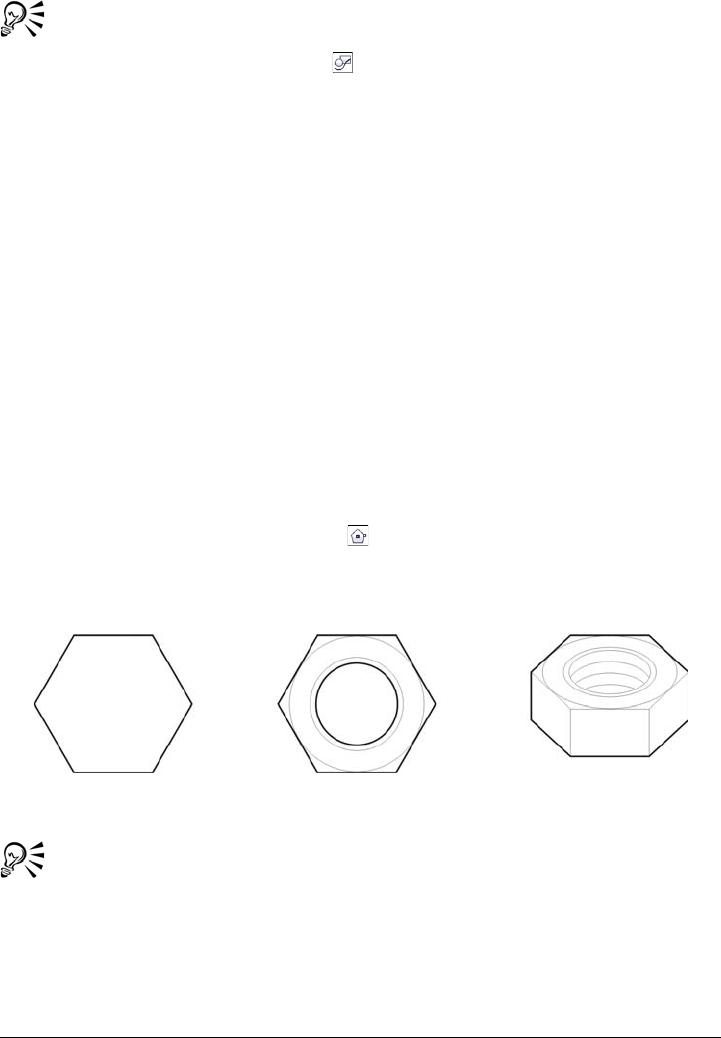
Drawing shapes 181
You can change the direction of a selected arc or a wedge by clicking the
Geometric properties button on the property bar and clicking Direction
in the Property manager docker.
Drawing polygons and stars
Corel DESIGNER lets you draw polygons and two types of stars: perfect and complex.
You can draw polygons and stars and then reshape them. For example, you can convert
a polygon to a star by dragging its nodes, and you can change the number of sides on a
polygon.
Perfect stars are traditional-looking stars and can have a fill applied to the entire star
shape. Complex stars have intersecting sides and produce original results with a fill
applied.
You can also draw a predefined star shape. For more information, see “To draw a
predefined shape” on page 183.
To draw a polygon
1Click the Center-point polygon tool .
2Point to where you want the center, and drag in the drawing window until the
polygon is the size you want.
Example of using a polygon to create a nut
You can change a polygon to a star by selecting the polygon with the Shape
tool, clicking a node on one of the sides, and dragging toward the center of the
polygon.
182 Corel DESIGNER X6 User Guide
To draw a star
To reshape a polygon
To modify a star
When you use the Shape tool to reshape a perfect star, the node movement is
constrained. Also, you cannot add or delete nodes, or convert line segments to
curves.
To Do the following
Draw a perfect star In the toolbox, click the Star tool , and
drag in the drawing window until the star is
the size you want.
Draw a complex star In the toolbox, click the Complex star
tool , and drag in the drawing window
until the star is the size you want.
To Do the following
Reshape a polygon Click the Shape tool , and click a node on
the polygon. Drag the node to change the
polygon’s shape.
Change the number of sides of a polygon Select a polygon. Type a value in the Points
or sides box on the property bar, and press
Enter.
To Do the following
Change the number of points on a star Select a star, type a value in the Points or
sides box on the property bar, and press
Enter.
Reshape a star Select a star, click the Shape tool , and
drag a node on the star.
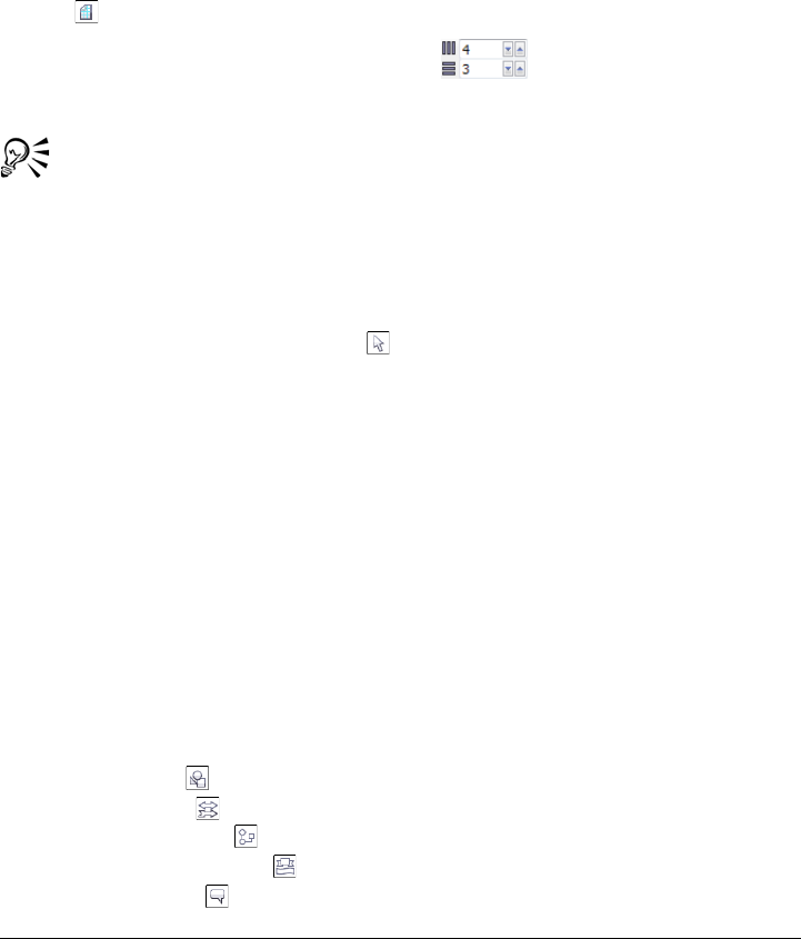
Drawing shapes 183
Drawing grids
You can draw a grid and set the number of rows and columns. A grid is a grouped set
of rectangles that you can break apart.
To draw a grid
1In the toolbox, click the Rectangle tools button, and click the Graph paper
tool .
2Type values in the Columns and rows box on the property bar.
3Drag diagonally to draw the grid.
If you want to draw the grid from its center point outward, hold down Shift as
you drag. If you want to draw a square grid, hold down Ctrl as you drag; if the
grid has an equal number of rows and columns, the cells will be square as well.
To ungroup a grid
1Select a grid by using the Pick tool .
2Click Arrange Ungroup.
Drawing predefined shapes
You can draw predefined shapes, such as basic shapes, arrows, and stars using the Perfect
Shapes collection. Basic shapes, arrow shapes, and star shapes have glyphs which let you
modify their appearance.
You can add text to the inside or outside of the shape. For example, you might want to
put a label inside a flowchart symbol.
To draw a predefined shape
1Click the Perfect Shapes tools button, and click one of the following tools:
• Basic shapes
• Arrow shapes
• Flowchart shapes
• Miscellaneous shapes
• Callout shapes

184 Corel DESIGNER X6 User Guide
2Open the Perfect shapes picker on the property bar, and click a shape.
3Drag in the drawing window until the shape is the size you want.
Perfect Shapes can be modified like any other shapes.
To modify a predefined shape
1Select a shape with a glyph.
2Drag the glyph until the shape is modified the way you want.
The right-angle triangle, explosion, and flowchart shapes do not have glyphs.
To add text to a predefined shape
1Click the Te x t tool .
2Position the cursor inside the shape’s outline until it changes to a text cursor
box , and then click.
3Type and format text inside the shape.
Drawing projected shapes
You can draw thread shapes, well shapes, cylinders, and prisms in projected view. These
shapes are useful for creating illustrations of bolts, nuts, and well nuts.
You can adjust the length and radius of the projected shapes by specifying values or by
moving their control handles in the drawing window.
With thread and well shapes, you can set the distance from the first thread to the start
of the object and the distance from the last thread to the end of the object. You can also
adjust the pitch, which is the distance in projected space from one thread to the next,
or adjust the number of threads per inch.
With prisms, you can specify the number of sides of the base faces.
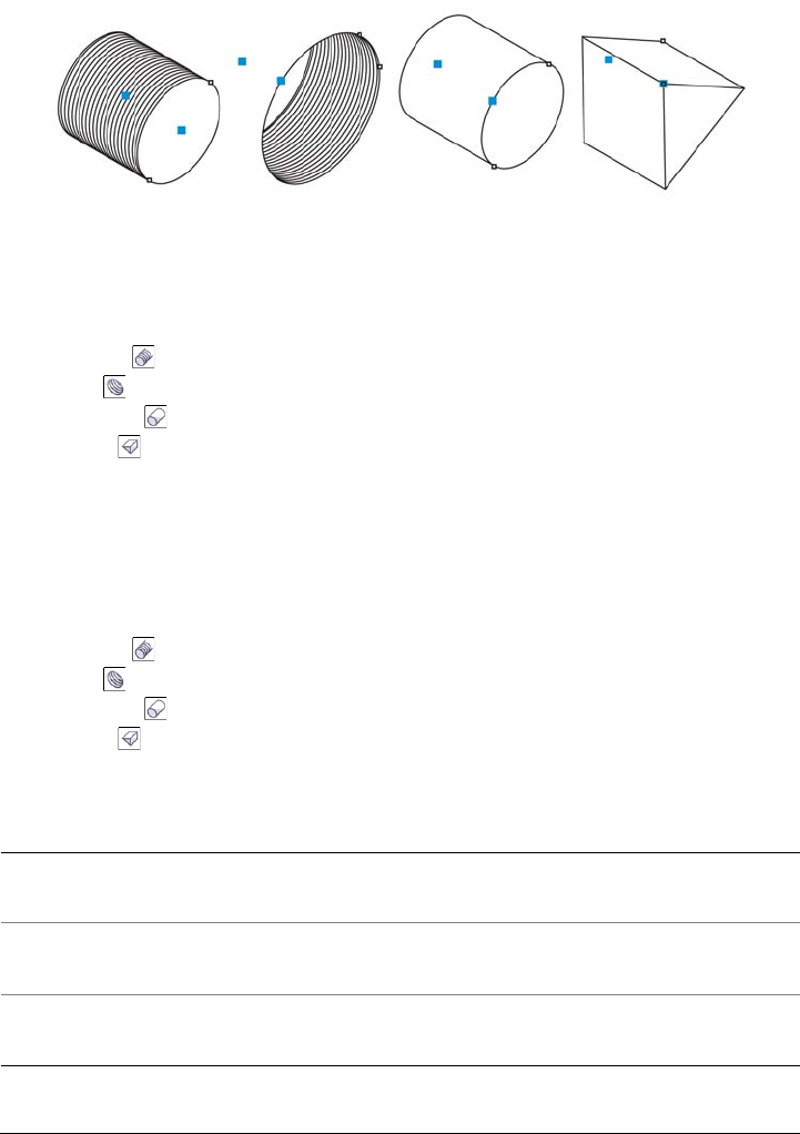
Drawing shapes 185
Examples of projected shapes
To draw a projected shape
1Click the Projected shape tools button, and click one of the following tools:
• Thread
• Well
• Cylinder
• Prism
2Drag in the drawing window to set the radius of the shape, then move the pointer
to set the length, and click.
To modify a projected shape
1Click the Projected shape tools button, and click one of the following tools:
• Thread
• Well
• Cylinder
• Prism
2Click the projected shape, and perform any of the following tasks.
To Do the following
Set the radius Type a value in the top portion of the Radius
and length box on the property bar.
Set the length Type a value in the bottom portion of the
Radius and length box on the property bar.
Set the pitch of a thread or well shape Click the Pitch button on the property bar,
and type a value in the Pitch box.
186 Corel DESIGNER X6 User Guide
The radius, length, and distance values are applied in projected space.
To adjust a projected shape by using control handles
1Using a projected shape tool, click the shape.
2Perform any of the following tasks:
Set the number of threads per inch for a
thread or well shape
Click the Threads per inch button on the
property bar, and type a value in the
Threads per inch box.
Set the distance between the start of a well
or thread shape and the first thread
Type a value in the top portion of the
Distance from start or end box.
Set the distance between the end of a well or
thread shape and the last thread
Type a value in the bottom portion of the
Distance from start or end box.
Specify the number of sides of the base faces
of a prism
Type a value in the Sides box.
To Do the following
Adjust the shape radius Drag the radius control handle.
Adjust the shape length Drag the length control handle.
Rotate a prism Drag the radius control handle.
To Do the following

Drawing shapes 187
Using control handles to adjust the radius (left) and length (right) of a thread
shape
Drawing by using shape recognition
You can use the Smart drawing tool to draw freehand strokes that can be recognized
and converted to basic shapes. Rectangles and ellipses are translated to native
Corel DESIGNER objects; trapezoids and parallelograms are translated to Perfect
Shapes objects; lines, triangles, squares, diamonds, circles, and arrows are translated to
curve objects. If an object is not converted to a shape, it is smoothed. Objects and curves
drawn with shape recognition are editable. You can set the level at which
Corel DESIGNER recognizes shapes and converts them to objects. You can also specify
the amount of smoothing applied to curves.
You can set the length of time to elapse between drawing the shape and the
implementation of shape recognition. For example, if the timer is set to one second and
you draw a circle, shape recognition takes effect one second after you draw the circle and
release the mouse button.
You can make corrections as you draw. You can also change the thickness and line style
of a shape that was drawn using shape recognition.
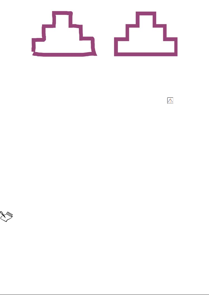
188 Corel DESIGNER X6 User Guide
Shapes created with the Smart drawing tool are recognized and smoothed.
To draw a shape or line by using shape recognition
1Click the Curve tools button, and click the Smart drawing tool .
2Choose a recognition level from the Shape recognition level list box on the
property bar.
3Choose a smoothing level from the Smart smoothing level list box on the
property bar.
4Draw a shape or line in the drawing window.
To set shape recognition delay
1Click To o l s Options.
2In the Wo rk s pa ce list of categories, double-click To o l b o x .
3Click Smart drawing tool.
4Move the Drawing assistance delay slider.
The slider moves in increments of 0.25 seconds; the maximum delay is 2
seconds.
To make a correction while using shape recognition
• Before the recognition delay has elapsed, hold down Shift, and drag over the area
that you want to erase. Release Shift to continue drawing.
You must start erasing the shape or line from the last point drawn.

Drawing shapes 189
If you are drawing a freehand shape consisting of several curves, you can delete
the last curve drawn by pressing Esc.
To change the outline thickness of an object drawn with shape recognition
1Click the Curve tools button, and click the Smart drawing tool .
2Click the shape.
3From the Outline width list box on the property bar, choose an outline thickness.
When lines drawn with the Smart drawing tool overlap, the outline thickness
is determined by the average.
You can change the line style of a shape drawn with shape recognition. For
more information, see “To specify line and outline settings” on page 160.

Shaping objects 191
Shaping objects
You can shape objects in various ways.
This section contains the following topics:
• Working with curve objects
• Shaping curve objects by using Reflect Nodes mode
• Cropping, splitting, and erasing objects
• Trimming objects
• Filleting, scalloping, and chamfering corners of curve objects
• Welding and intersecting objects
• Creating new objects from boundaries
• Creating PowerClip™ objects
• Smudging and smearing objects
•Adding twirl effects
• Roughening objects
• Shaping objects by attracting or pushing away nodes
• Applying distortion effects
• Shaping objects by using envelopes
For more information about working with paths and subpaths, see “Reference: Shaping
objects” on page 233.
Working with curve objects
Objects can be shaped by manipulating their nodes and segments. An object’s nodes are
the tiny squares that appear along the object’s outline. The line between two nodes is
called a segment. Moving an object’s segments lets you make coarse adjustments to the
object’s shape, while changing the position of its nodes lets you fine-tune the shape of
the object.
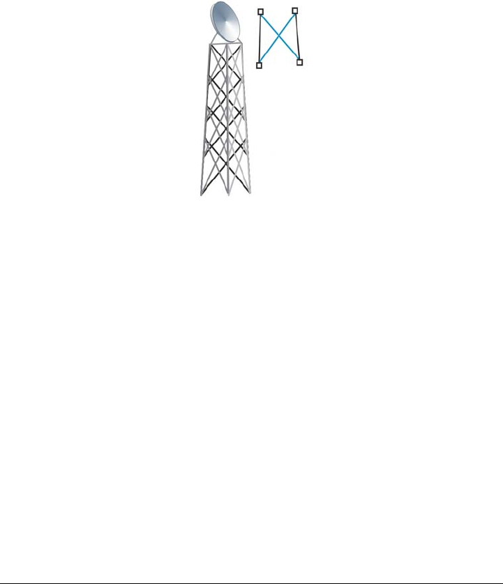
192 Corel DESIGNER X6 User Guide
Most objects that are added to a drawing are not curve objects, with the exception of
freehand and Bézier curves. Therefore, if you want to customize the shape of an object,
it is recommended that you convert that object to a curve object. By converting objects
to curves, you can shape them by adding, removing, positioning, aligning, or
transforming their nodes. You can join two or more open curves or arcs to make a single
curve object, and you can convert curve objects to ellipses, if they have a basic ellipse
shape to begin with.
Joining multiple line segments can be the starting point for a more complex
drawing.
Before you can manipulate an object’s nodes, you must select them. When working
with curve objects, you can select individual, multiple, or all of the object’s nodes.
Selecting multiple nodes lets you shape different parts of an object simultaneously.
When you add nodes, you increase the number of segments, and therefore the amount
of control you have over the shape of the object. You can also remove nodes to simplify
an object’s shape.
When you create an object, it is made up of one or multiple paths. If you are working
on an open object, such as a freehand curve, you can join its start and end nodes. When
you join the start and end nodes, the two nodes are pulled together to create a closed
object. You can add color to the inside of closed paths that you create. For information
on applying fills, see “Filling objects” on page 361. If the paths consist of multiple
subpaths, you can break the paths apart to extract a subpath. For information on
breaking paths apart, see “Cropping, splitting, and erasing objects” on page 198.
After you create a curve object, you can align its nodes horizontally or vertically.

Shaping objects 193
You can change the nodes on a curve object to one of four types: cusp, smooth,
symmetrical, or line. Cusp nodes make the node’s intersecting line take on the shape of
a corner or point when you adjust the position of the node’s control points. Smooth
nodes make the node’s intersecting line take on the shape of a curve. Each control point
can be shortened or lengthened independently, giving you smaller or larger angles to
work with. Symmetrical nodes make the node’s intersecting line take on the shape of a
curve as well as intersect the node at exactly the same angle. Line nodes let you shape
objects by changing the shape of their segments. You can make a curve segment straight
or a straight segment curved.
You can also change the direction of a segment by reversing the position of its start and
end nodes. The effect is visible only when the ends of a segment are different from each
other.
You can also shape objects by stretching, scaling, rotating, and skewing their nodes. For
example, you can scale the corner nodes of a curve object to enlarge the curve object
proportionally. Stretching, on the other hand, elongates a curve object so that its shape
is distorted. All or parts of a curve object can be rotated in a counterclockwise or
clockwise direction. You can also skew nodes to shape a curve object.
To convert objects to curve objects
1Select the object.
2Click Arrange Convert to curves.
You can convert artistic text to curves so that you can shape individual
characters.
To join curves
1Using the Pick tool , hold down Shift, and select each object.
2Click Arrange Join curves.
3In the Join curves docker, choose one of the following options:
• Extend
• Chamfer
• Fillet
• Bézier curve
4Click Apply.
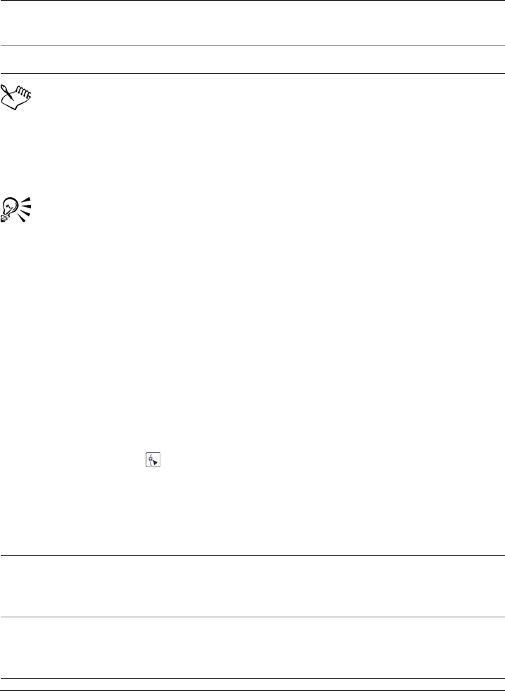
194 Corel DESIGNER X6 User Guide
You cannot join interior points, only endpoints.
Endpoints must be within the specified tolerance to be joined.
If endpoints to be joined do not share coordinates, the endpoints are extended
to their intersection.
You can also connect the subpaths in a group of objects.
You can also select curves by marquee selecting. If the curves are marquee
selected, the properties from the top object on a layer are used. You can verify
which object is the top one in the Object manager docker. If the Object
manager docker is not open, click Window Object manager.
To convert a curve to an ellipse
1Select the curve object to convert.
2Click Arrange Convert to ellipse.
To select a node
1Click the Shape tool .
2Select a curve object.
3Click a node.
You can also
Specify the maximum distance between
endpoints
Type a value in the Gap tolerance box.
Specify the radius Type a value in the Radius box.
You can also
Marquee select multiple nodes On the property bar, choose Rectangular
from the Selection mode list box, and drag
around the nodes that you want to select.
Freehand marquee select multiple nodes On the property bar, choose Freehand from
the Selection mode list box, and drag
around the nodes that you want to select.
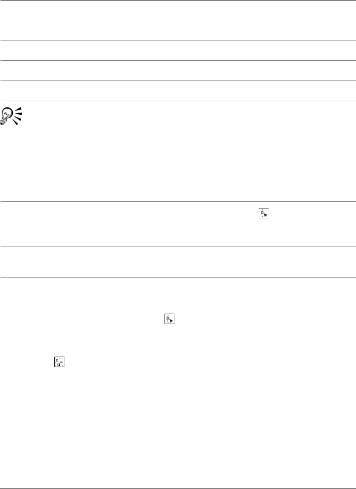
Shaping objects 195
When a curve is selected with the Shape tool, you can select the first node in
a curve object by pressing Home, or the last node by pressing End.
To add or remove a node
To reduce the number of nodes in a curve object
1In the toolbox, click the Shape tool .
2Click a curve object, and do one of the following:
• To reduce the number of nodes in the entire object, click the Select all nodes
button on the property bar.
• To reduce the number of nodes in a part of a curve object, marquee select the part
that you want to change.
3Do one of the following:
• Click Reduce nodes on the property bar to have overlapping and redundant
nodes automatically removed.
• Move the Curve smoothness slider to control the number of nodes that are
removed. Removing many nodes can reshape the curve object.
Select multiple nodes Press Shift, and click each node.
Select all nodes on a selected curve Click Edit Select all Nodes.
Deselect a node Press Shift, and click a selected node.
Deselect multiple nodes Press Shift, and click each selected node.
Deselect all nodes Click a blank space in the drawing window.
To Do the following
Add a node Click the Shape tool , select a curve
object, and double-click where you want to
add a node.
Delete a node Click the Shape tool, select a curve object,
and double-click a node.
You can also
196 Corel DESIGNER X6 User Guide
To join the end nodes of a single subpath
1Click the Shape tool .
2Click a subpath.
3Click the Close curve button on the property bar.
You can close multiple subpaths by clicking Arrange Join curves.
To join the nodes of multiple subpaths
1Click the Shape tool .
2Hold down Shift, and click a node from each subpath.
3Click the Extend curve to close button on the property bar.
If you want to join nodes from separate curve objects, you must first combine
them into a single curve object, and then join the end nodes of the new
subpaths. For information about combining objects, see “Combining objects”
on page 271.
To align nodes
1Click the Shape tool .
2Select a curve object.
3Hold down Shift, and select the nodes that you want to align.
4Click the Align nodes button on the property bar.
5In the Node align dialog box, enable the alignment options you want.
To make a node cusp, smooth, or symmetrical
1Click the Shape tool .
2Click a node.
3On the property bar, click one of the following buttons:
• Cusp node
• Smooth node
• Symmetrical node
Shaping objects 197
You can also change an existing node from one type to another by using
shortcut keys. To change a smooth node to a cusp node or a cusp node to a
smooth node, click the node using the Shape tool, and press C. To change a
symmetrical node to a smooth node or a smooth node to a symmetrical node,
click the node using the Shape tool, and press S.
To manipulate a curve object’s segments
1Click the Shape tool .
2Select a curve object.
3Drag a segment until it’s the shape you want.
To stretch, scale, rotate, or skew nodes
1Click the Shape tool .
2Select a curve object.
3Select the nodes along the curve that you want to transform.
4On the property bar, click one of the following buttons:
• Stretch or scale nodes
• Rotate or skew nodes
5Drag a set of handles to transform the nodes.
You can also
Straighten a curve segment Click a curve segment, and click the
Convert to line button on the property
bar.
Curve a straight segment Click a straight segment, and click the
Convert to curve button on the
property bar.
Change the direction of the curve Click a segment, and click the Reverse
direction button on the property bar.
198 Corel DESIGNER X6 User Guide
Shaping curve objects by using Reflect Nodes mode
Reflect Nodes mode lets you edit nodes and have the same edits take place in reverse on
corresponding nodes. For example, you can move a node to the right and have its
corresponding node move the same distance to the left.
This is useful when you want to shape curve objects and have the changes mirrored
across their left and right or top and bottom.
Usually, you will start with one curve object that is more or less symmetrical, or two
curve objects, where the second was created by mirroring the first.
To shape a curve object by using Reflect Nodes mode
1Click the Shape tool .
2Select corresponding nodes on the left and right or top and bottom.
To select multiple nodes, drag to select the nodes, or click a node, hold down Shift,
and click each additional node.
3On the property bar, click one of the following buttons:
• Reflect nodes vertically
• Reflect nodes horizontally
4Edit the nodes on one side.
The changes occur in reverse on corresponding nodes on the other side.
To shape multiple objects by using Reflect Nodes mode, click the first object,
and drag to select nodes; or hold down Shift, and click each node on the first
object. Then hold down Shift, click the second object, and drag to select nodes,
or hold down Shift and click each node on the second object.
Cropping, splitting, and erasing objects
You can crop, split, and erase portions of objects.
Cropping objects
Cropping lets you quickly remove unwanted areas in objects and imported graphics,
eliminating the need to ungroup objects, break linked groups apart, or convert objects
to curves. You can crop vector objects and bitmaps.

Shaping objects 199
Cropping objects
When cropping objects, you define a rectangular area (cropping area) that you want to
keep. Object portions outside the cropping area are removed. You can specify the exact
position and size of the cropping area, and you can rotate and resize it. You can also
remove the cropping area.
You can crop only selected objects without affecting other objects in a drawing, or you
can crop all objects on the drawing page. In either case, the affected text and shape
objects are automatically converted to curves.
Splitting objects
You can split a bitmap or vector object in two and reshape it by redrawing its path. You
can split a closed object along a straight or jagged line. Corel DESIGNER lets you
choose between splitting an object into two objects, or leaving it as one object composed
of two or more subpaths. You can specify whether you want to close the paths
automatically or keep them open.
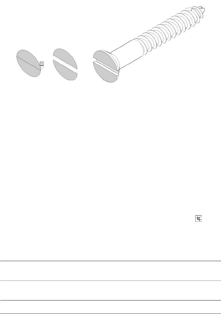
200 Corel DESIGNER X6 User Guide
The Knife tool creates two separate objects by cutting the ellipse in half. The
two objects are separated and used to form the top of the screw.
Erasing portions of objects
You can erase unwanted portions of bitmaps and vector objects. Erasing automatically
closes any affected paths and converts the object to curves. If you erase connecting lines,
you create subpaths rather than individual objects. You can also delete portions of
objects, called virtual line segments, that are between intersections. For example, you
can delete loops from a curved line, or you can delete interior lines from overlapping
shapes.
To crop objects
1Select the objects that you want to crop.
If no objects on the drawing page are selected, all objects will be cropped.
2In the toolbox, click the Deletion tools button, and click the Crop tool .
3Drag to define a cropping area.
4Double-click inside the cropping area.
You can also
Specify the exact position of the cropping
area
Type values in the Crop position boxes on
the property bar, and press Enter.
Specify the exact size of the cropping area Type values in the Crop size boxes on the
property bar, and press Enter.
Shaping objects 201
Objects on locked, hidden, Grid, or Guides layers cannot be cropped. Also, you
cannot crop OLE and Internet objects, rollovers, or the content of PowerClip™
objects.
During cropping, affected linked groups, such as contours, blends, and
extrusions, are automatically broken apart.
You can move, rotate, and size the cropping area interactively as you would any
object. To move the cropping area, drag it to a new position. To size the
cropping area, drag any of its handles . To rotate the cropping area, click
inside, and drag a rotation handle .
You can remove the cropping area by pressing Esc.
To split an object
1Click the Deletion tools button, and click the Knife tool .
2Position the Knife tool over the object’s outline where you want to start cutting.
The Knife tool snaps upright when positioned properly.
3Click the outline to start cutting.
4Position the Knife tool where you want to stop cutting, and click again.
Rotate the cropping area Type values in the Angle of rotation box on
the property bar.
Remove the cropping area Click Clear crop marquee on the property
bar.
You can also
Split an object along a freehand curve Point to where you want to start the cut, and
drag to where you want it to end.
You can also
202 Corel DESIGNER X6 User Guide
By default, objects are split into two objects and paths are automatically closed.
When you use the Knife tool on a selected object, the object becomes a curve
object.
To divide an object into equal segments
1Select the object that you want to divide.
2Click Arrange Shaping Equal divide.
3In the Shaping docker, specify the following:
• Divisions — number of segments to divide the object into
• Gap — amount of space between segments
If you want to group the segments after the divide, enable the Group divisions
check box.
If you want the segments to be combined as one object, enable the Combine
divisions check box. Disable the check box if you want the segments to be
individual objects.
Split an object along a Bézier curve Hold down Shift, click where you want to
start cutting an object, drag the control
handle to where you want to position the
next node, and click. Continue clicking to
add more straight segments to the line.
If you want to add a curved segment, point
to where you want to place the node and
drag to shape the curve.
If you want to constrain the line to 15-
degree increments, hold down Shift + Ctrl.
Split an object into two subpaths Click the Keep as one object button on
the property bar.
Split an object while keeping only one of its
parts
Click the object’s outline where you want to
start the cut, and point to where you want
the cut to end. Press Ta b once or twice until
only the part of the object that you want to
keep is selected, and then click.
You can also
Shaping objects 203
If you do not want to delete the original object, disable the Delete selected object
check box.
4Click Apply.
This feature creates a copy of the object and applies the divisions to the new
object. If you do not delete the original object, you will have two objects one
on top of the other, and the object will appear unchanged.
The resulting object inherits the original object’s edge and fill properties.
You can divide curves, arcs, rectangles, and polygons. To divide other objects,
you must first convert them to curves. You cannot divide images.
You can select multiple objects to divide at one time. If you also enable the
Group divisions check box, all the objects that you divide are grouped into a
single group.
To break a path
To erase portions of an object
1Select an object.
2Click the Deletion tools button, and click the Eraser tool .
3Drag over the object.
To Do the following
Break a path Click the Shape tool . Select a node, and
click the Break curve button on the
property bar.
Extract a broken path from an object Click the Shape tool . Right-click a path,
and click Break apart. Select a segment,
node, or group of nodes that represents the
portion of the path that you want to extract,
and click the Extract subpath button on
the property bar.
204 Corel DESIGNER X6 User Guide
When you erase portions of objects, any affected paths are automatically
closed.
You can erase in straight lines by clicking where you want to start erasing, and
then clicking where you want to finish erasing. Hold down Ctrl if you want to
constrain the line’s angle.
You can also erase an area of a selected object by double-clicking the area with
the Eraser tool.
To delete a virtual line segment
1Click the Deletion tools button, and click the Virtual segment delete tool .
2Move the pointer to the line segment that you want to delete.
The Virtual segment delete tool snaps upright when positioned properly.
3Click the line segment.
You can also
Change the size of the eraser nib Type a value in the Eraser thickness box on
the property bar, and press Enter.
Change the shape of the eraser nib Click the Eraser shape button on the
property bar.
Maintain all the nodes of the area that is
being erased
Disable the Reduce nodes button on the
property bar.
You can also
Delete multiple line segments at the same
time
Drag the pointer to enclose or intersect all
target segments.
Delete a virtual line segment that intersects
with a curve
Hold down Alt and drag to draw a curve.
Weld line segments Hold down Shift, and click the two
overlapping end points. You can also hold
down Alt + Shift and drag to marquee
select the overlapping nodes.

Shaping objects 205
The Virtual segment delete tool does not work on linked groups (like drop
shadows), text, or images.
Trimming objects
Trimming creates irregularly shaped objects by removing object areas that overlap. You
can trim almost any object, including clones, objects on different layers, and single
objects with intersecting lines. However, you cannot trim paragraph text, dimension
lines, or masters of clones.
Before you trim objects, you must decide which object you want to trim (the target
object) and which object you want to use to perform the trimming (the source object).
For example, if you want to create a star-shaped cutout of a square object, the star is the
source object because you are using it to trim the square. The square is the target object
because it’s the object that you want to trim. The source object trims the part of the
target object it overlaps. For example, if you trim a rectangle by using a circle, the area
of the rectangle that was covered by the circle is removed, creating an irregular shape.
The target object retains its fill and outline attributes.
Corel DESIGNER lets you trim objects in different ways. You can use a front object as
the source object to trim an object behind it, or use the back object to trim a front
object. You can also remove hidden areas of overlapping objects, so that only the visible
areas remain in the drawing. Removing the hidden areas can reduce file size when you
convert vector graphics to bitmaps.
To trim an object
1Select the source and target objects.
2Click Arrange Shaping Tr i m .
3In the Shaping docker, click Indicate target.
4Click the object to trim.
If you want to delete objects during the trim, enable the Delete selected
object or Delete target object check box in the Shaping docker.

206 Corel DESIGNER X6 User Guide
To trim front and back objects
1Marquee select the source and target objects.
2Click Arrange Shaping, and click one of the following:
• Back minus front — removes the front object from the back one
• Front minus back — removes the back object from the front one
3Click Apply in the Shaping docker.
You can trim the control object of a PowerClip object so that the object inside
the PowerClip object assumes the new shape of the PowerClip container. For
information about PowerClip objects, see “Creating PowerClip objects” on
page 212.
Text on a path is converted to a curve object before it is trimmed.
To trim overlapping areas among objects
1Marquee select the objects that you want to trim.
2Click Arrange Shaping Simplify.
3Click Apply in the Shaping docker.
You can trim the control object of a PowerClip object, so that the object inside
the PowerClip object assumes the new shape of the PowerClip container. For
information about PowerClip objects, see “Creating PowerClip objects” on
page 212.
Text on a path is converted to a curve object before it is trimmed.
Filleting, scalloping, and chamfering corners of curve objects
You can fillet, scallop, or chamfer the corners of any curve object, whether it originates
from a shape, lines, text, or a bitmap. Filleting produces a rounded corner, scalloping
rounds and inverts the corner to create a notch, and chamfering bevels a corner so that
it appears flat. Corel DESIGNER also lets you preview the corners before you apply the
changes to them. For information about modifying the corners of squares and
rectangles, see “Drawing rectangles and squares” on page 175.

Shaping objects 207
The cabinet doors have different styles applied to the corners. From left to right
you can see standard corners, filleted corners, scalloped corners, and chamfered
corners.
When you fillet, scallop, or chamfer non-curve shapes, they are automatically converted
to curves. Text objects must be converted to curves manually by using the Convert to
curves command. Changes apply to all corners unless you select individual nodes. You
cannot fillet, scallop, or chamfer a smooth or symmetrical curve; the corner must be
created by two lines that intersect at an angle of less than 180 degrees.
If a fillet, scallop, or chamfer value is too high, the operation is not applied to some or
all of the corners. This occurs when line segments aren’t long enough to apply the radius
or chamfer distance. Even if the line segments appear long enough at the beginning of
the operation, you must consider that the line segments shorten as the radius or chamfer
values are applied across the object.
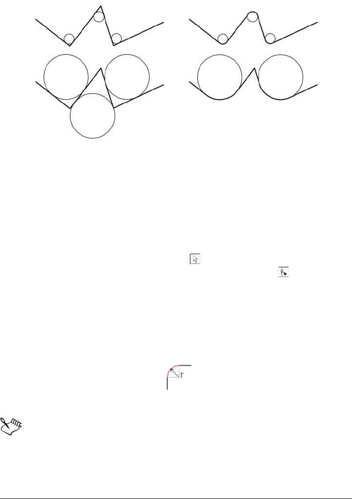
208 Corel DESIGNER X6 User Guide
In the example above, the circles represent fillet radius settings. The upper lines
show the proposed fillets on the left and the successful results on the right. The
lower lines also show the proposed fillets on the left, but the results on the right
show that not all corners are filleted. After the first fillet is applied, the next
corner can’t be filleted because the line segment isn’t long enough. This corner
is skipped, and the final corner is filleted.
To round object corners by filleting
1 Do one of the following:
• Select a curve object using the Pick tool .
• Select individual nodes on a curve object using the Shape tool .
2Click Window Fillet/Scallop/Chamfer.
3In the Fillet/Scallop/Chamfer docker, enable the Fillet option.
4Type a value in the Radius box.
The radius is used to create a circular arc whose center is equidistant from either
side of a corner. Higher values produce more rounded corners.
5Click Apply.
The Apply button is disabled if no valid objects or nodes are selected.
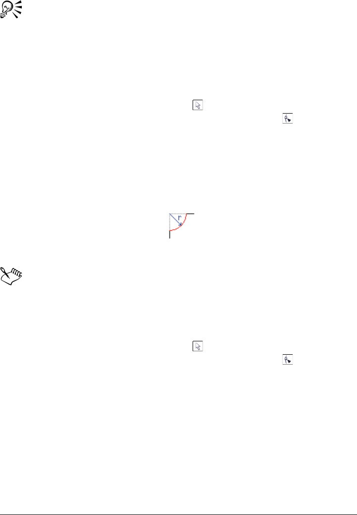
Shaping objects 209
If you have a square or rectangle, you can also round all corners at once by
dragging a corner node toward the center of the object while the Shape tool is
active. The shape is not converted to curves if you use this method.
To scallop object corners
1 Do one of the following:
• Select a curve object using the Pick tool .
• Select individual nodes on a curve object using the Shape tool .
2Click Window Fillet/Scallop/Chamfer.
3In the Fillet/Scallop/Chamfer docker, enable the Scallop option.
4Type a value in the Radius box.
The radius value is measured from the original corner point to create a scalloping
arc.
5Click Apply.
The Apply button is disabled if no valid objects or nodes are selected.
To bevel object corners by chamfering
1 Do one of the following:
• Select a curve object using the Pick tool .
• Select individual nodes on a curve object using the Shape tool .
2Click Window Fillet/Scallop/Chamfer.
3In the Fillet/Scallop/Chamfer docker, enable the Chamfer option.
4In the Chamfer distance area, type a value in the A box to set where the chamfer
will begin in relation to the original corner.

210 Corel DESIGNER X6 User Guide
If you do not want the ends of the chamfer to be equidistant from the original
corner, click the Lock button , and type a different value in the B box. A and B
values are applied according to the direction in which the line is drawn.
5Click Apply.
Welding and intersecting objects
You can create irregular shapes by welding and intersecting objects. You can weld or
intersect almost any object, including clones, objects on different layers, and single
objects with intersecting lines. However, you cannot weld or intersect paragraph text,
dimension lines, or masters of clones.
You can weld objects to create one object with a single outline. The new object uses the
welded objects’ perimeter as its outline and adopts the fill and outline properties of the
target object. All intersecting lines disappear.
You can weld objects regardless of whether they overlap each other. If you weld objects
that do not overlap, they form a weld group that acts as a single object. In both cases,
the welded object takes on the fill and outline attributes of the target object.
You can weld single objects with intersecting lines so that the object breaks into several
subpaths, but its appearance remains the same.
Intersecting creates an object from the area where two or more objects overlap. The
shape of this new object can be simple or complex, depending on the shapes you
intersect. The new object’s fill and outline attributes depend on the object you define as
the target object.
To weld an object
1Select the source object or objects.
2Click Arrange Shaping We ld.
3In the Shaping docker, click Indicate target.
4Click the object to weld.

Shaping objects 211
If you want to delete objects during welding, enable the Delete selected
object or Delete target object check box.
To intersect an object
1Select the source object or objects.
2Click Arrange Shaping Intersect.
3In the Shaping docker, click Indicate target.
4Click the object to intersect with.
If you want to delete objects, enable the Delete selected object or Delete
target object check box.
To intersect multiple objects, marquee select the source objects.
Creating new objects from boundaries
You can draw a boundary around the outer or inner edges of complex shapes to create
a new closed curve object with the current properties (line weight, fill color, and so on).
During this process, if you specify a point outside the selected objects, an outline is
wrapped around the outside edge. If you specify a point on the inside of selected objects,
an outline is drawn around the inner edges. If the objects do not overlap, each object is
outlined separately. Error messages appear if you click directly on a line or if there is not
sufficient space to create the boundary.
Boundaries cannot be drawn around text, bitmaps, or open line endings.
To create a new object from a boundary
1Select the objects for the boundary.
2Click Arrange Shaping Boundary.
If you want the boundary object to be placed behind the current objects, enable the
Place behind selected option in the Shaping docker.
3Click Indicate target.
4Click a point outside or inside the selected objects.
212 Corel DESIGNER X6 User Guide
If you want to delete the original objects, enable Delete selected object.
Creating PowerClip objects
Corel DESIGNER lets you place vector objects and bitmaps, such as photos, inside
other objects, or containers. A frame can be any object, for example artistic text or a
rectangle.When the object is larger than the frame, the object, called the contents, is
cropped to fit the form of the frame. This creates a PowerClip object.
You can create more complex PowerClip objects by placing one PowerClip object inside
another to produce a nested PowerClip object. You can also copy the contents of one
PowerClip object to another.
You can create an empty PowerClip frame from an object, or convert a PowerClip frame
back to an object. Creating empty PowerClip frames or text frames is useful when you
want to define the layout of your document before adding the content. For more
information about text frames, see “Adding paragraph text” on page 457. After you
create an empty PowerClip frame, you can add contents to it. You can also add contents
to a PowerClip frame that already contains another object.
After you create a PowerClip object, you can select or edit its contents, or reposition the
contents inside the frame. Whenever a PowerClip object is selected, a floating toolbar
appears.
The PowerClip toolbar lets you edit, select, extract, lock, or reposition the
contents inside the frame. The toolbar appears whenever a PowerClip object is
selected.
You can lock the PowerClip contents, so that when you move the frame, the content
moves with it. If you want to delete the contents of a PowerClip object or modify it
without affecting the frame, you can extract the contents.
You can set the default behavior for dragging content to PowerClip frames, centering
new content, and marking empty PowerClip frames.
To create a PowerClip object
1Select the object that you want to use as PowerClip contents.

Shaping objects 213
2Click Effects PowerClip Place inside frame.
3Click the object that you want to use as a frame.
If you want to create a nested PowerClip object, drag the PowerClip object inside
another PowerClip object, and hold down the W key as you release the mouse
button to place the object inside the frame.
You can also right-click an object or a group of objects, click PowerClip
inside, and then click the object that you want to use as a frame.
If the content is placed so that it falls outside the frame in its current position,
it is automatically centered inside the frame to make it visible. To change this
setting, click To o l s Options, choose PowerClip frame in the Wo rks pac e
list of categories, and set the options you want in the Auto-center new
content area.
To create an empty PowerClip frame
1Select an object that you want to use as a frame.
2Click Effects PowerClip Create empty PowerClip frame.
You can also right-click the object, choose Frame type, and click Create
empty PowerClip frame.
You can also click the PowerClip frame button on the Layout toolbar. To
open the Layout toolbar, click View To o l b a r s Layout or Layout Layout
toolbar.
To add content to a PowerClip frame
1Drag an object to the PowerClip frame.
When the object approaches the frame, the frame is highlighted.
2Do one of the following:
• To add the object to an empty PowerClip frame, release the mouse button.
• To add the object to a full PowerClip frame, hold down the W key as you release
the mouse button.
You can also drag content to the PowerClip frame directly from
Corel CONNECT, or from the Connect docker.

214 Corel DESIGNER X6 User Guide
If the content is placed so that it falls outside the frame, it is automatically
centered inside the frame to make it visible. To change this setting, click To o l s
Options, choose PowerClip frame in the Wo rks pa c e list of categories, and
set the options you want in the Auto-center new content area.
To convert a PowerClip frame back to an object
• Right-click the PowerClip frame, choose Frame type, and click None.
If the frame contains content, the content is deleted when the frame reverts to
a regular object. To avoid losing the content, you can first extract it from the
PowerClip object.
You can also convert a frame back to an object by clicking the No frame
button on the Layout toolbar. To open the Layout toolbar, click View
To o l b a r s Layout or Layout Layout toolbar.
To select the contents of a PowerClip object
1Select the PowerClip object.
The PowerClip toolbar appears.
2Click the Select PowerClip contents button on the PowerClip toolbar.
To position the contents inside a PowerClip frame
1Select a PowerClip object.
2Perform a task from the following table.
To Do the following
Center the contents inside the PowerClip
frame
Click Effects PowerClip Center
contents.
Shaping objects 215
The Fit contents proportionally, Fill frame proportionally, and the Stretch
contents to fill frame commands modify the PowerClip contents. The content
remains modified even if you extract it from the frame.
You can also position the contents by clicking the Fit contents button on the
PowerClip toolbar and clicking a command.
Fit the contents proportionally inside the
PowerClip frame
Click Effects PowerClip Fit contents
proportionally.
The content is resized so that its longest
dimension fits inside the frame. The content
is not distorted, and its aspect ratio is
preserved. The whole content is visible, but
there may be empty areas in the frame.
Fill the PowerClip frame proportionally Click Effects PowerClip Fill frame
proportionally.
The content is resized so that it fills the
frame without being distorted. The content’s
aspect ratio is preserved. The frame is full,
but there may be parts of the content that
fall outside the frame and are not visible.
Fill the PowerClip frame by stretching the
contents
Click Effects PowerClip Stretch
contents to fill frame.
The content is resized and distorted so that it
fills the frame. The content’s aspect ratio is
not preserved. The frame is full, and all of
the content is visible.
To Do the following
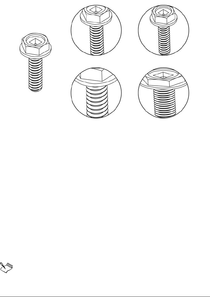
216 Corel DESIGNER X6 User Guide
Examples of PowerClip contents positioned by using the following commands:
Center contents (top left), Fit contents proportionally (top right), Fill
frame proportionally (bottom left), and Stretch contents to fill frame
(bottom right).
To copy the content of a PowerClip object
1Select an object.
2Click Effects Copy effect PowerClip from.
3Click a PowerClip object.
To edit the content of a PowerClip object
1Select a PowerClip object.
2Click Effects PowerClip Edit PowerClip.
3Edit the contents of the PowerClip object.
4Click Effects PowerClip Finish editing this level.
While you edit, the container is displayed in Wireframe mode and cannot be
selected.

Shaping objects 217
To lock or unlock the contents of a PowerClip object
1Select a PowerClip object.
2Click Effects PowerClip Lock contents to PowerClip.
When the content is unlocked, it is separated from the frame, so that the frame
can be moved independently. If you move the frame while the content is
unlocked, the content remains stationary and is not visible until you move the
frame over it.
You can also right-click a PowerClip object and click Lock contents to
PowerClip, or you can select the PowerClip object and click the Lock
contents to PowerClip button on the PowerClip toolbar.
To extract the content of a PowerClip object
1Select a PowerClip object.
2Click Effects PowerClip Extract contents.
You must extract the contents of each level in a nested PowerClip separately.
After the content is extracted, the frame remains as an empty PowerClip frame.
You can also right-click a PowerClip object and click Extract contents, or you
can select the PowerClip object and click the Extract contents button on the
PowerClip toolbar.
To set default options for PowerClip frames
1Click To o l s Options.
2In the Wo rk s pa ce category, click PowerClip frame.
3Perform a task from the following table.

218 Corel DESIGNER X6 User Guide
Smudging and smearing objects
Smudging and smearing let you shape an object by pulling extensions or making
indents along its outline. With smudging, the extensions and indents resemble streaks
that vary little in width as you drag with the Smudge brush tool. With smearing, the
extensions and indents have a more fluid shape that decreases in width as you drag with
the Smear tool.
To Do the following
Set the default behavior for dragging content
to a PowerClip frame
In the Drag content inside PowerClip
area, choose PowerClip with content or
Empty PowerClip from the list box, and
then choose one of the following options:
•Ignore PowerClip frame — places the
content on top of the PowerClip frame
instead of inside
•Add content to PowerClip frame
•Replace existing content (available only
for PowerClip frames with content)
Set the default behavior for centering new
content in a PowerClip frame
In the Auto-center new content area,
choose one of the following options:
•When content is completely outside
the frame — centers content only if it is
beyond the boundaries of the PowerClip
frame and will not be visible otherwise
•Always — always centers new content
•Never — turns off auto-centering
Mark empty PowerClip frames Enable the Show lines in empty
PowerClip frames check box, and choose
one of the following options:
•Always — displays lines in empty
PowerClip frames on screen and in printed
or exported documents
•On screen only — displays lines in empty
PowerClip frames only on screen
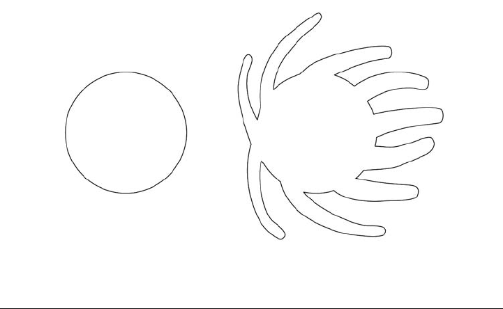
Shaping objects 219
Smudging objects
Smudging lets you distort an object by dragging its outline. When applying smudging
to an object, you can control the extent and shape of the distortion, whether you use a
pen tablet or a mouse.
The smudging effect responds to both the angle of rotation — or bearing — and the
tilt angle of the stylus (also known as a pressure-sensitive pen). Rotating the stylus
changes the angle of the smudging effect and tilting the stylus flattens the brush tip and
changes the shape of the smudging. If you are using a mouse, you can simulate the
bearing and tilt of the stylus by specifying values. Increasing the bearing angle from 0
to 359° changes the angle of the brushstroke. As you decrease the tilt angle from 90°
to 15°, you change the smudging shape by flattening the brush tip.
Smudging can respond to the pressure of a stylus on a pen tablet where the smudging
widens with more pressure and narrows with less. If you are using a mouse or want to
override stylus pressure, you can enter real values to simulate the pressure of a stylus on
a pen tablet. Negative values to -10 create a narrowing distortion, 0 maintains an even
stroke width, and positive values to 10 create an expanding distortion.
Whether you are using a pen tablet or a mouse, you must specify the nib size. The nib
size determines the width of the smudging applied to an object.
You can apply the smudging effect to the inside and outside of an object.
Smudging objects
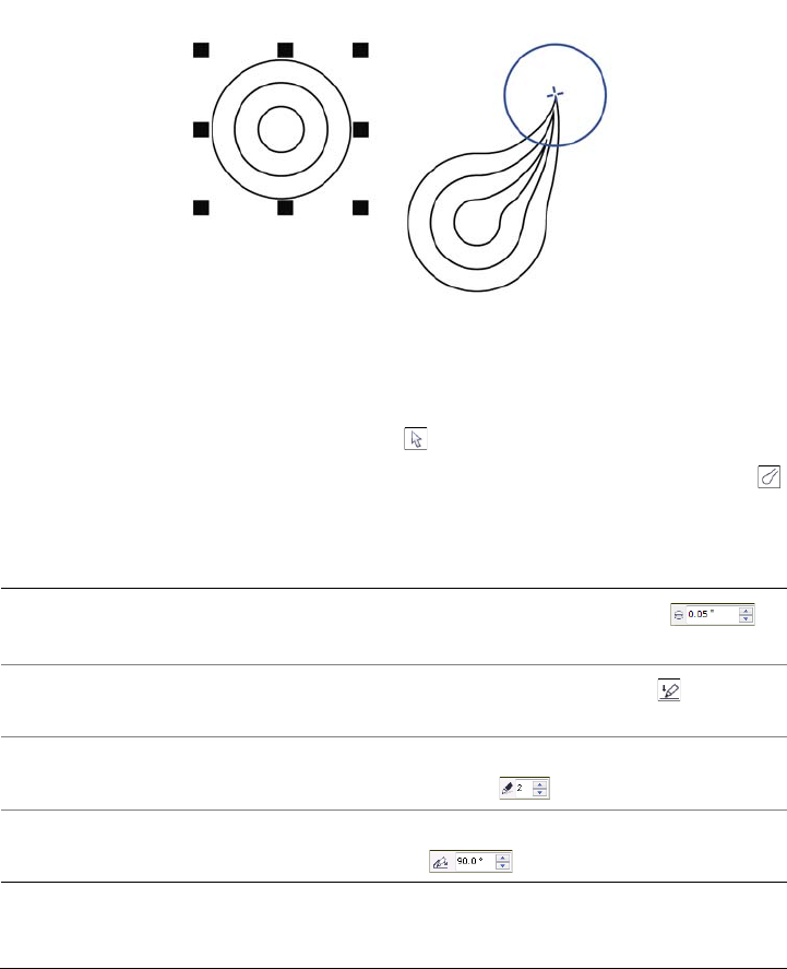
220 Corel DESIGNER X6 User Guide
Smearing objects
To control the smearing effect, you can set the size of the brush nib and the amount of
effect to apply, and you can use the pressure of your digital pen. You can use smooth
curves or curves with sharp corners when smearing objects.
Smearing an object
To smudge an object
1Select a curve object using the Pick tool .
2Click the Shape tools button in the toolbox, and click the Smudge brush tool .
3Drag around the outline to distort it.
You can also
Change the size of the brush nib Type a value in the Nib size box
on the property bar.
Change the size of the brush nib when using
a pen tablet
Click the Pen pressure button on the
property bar, and apply pressure to the pen.
Widen or narrow the smudging Type a value between -10 and 10 in the
Dryout box on the property bar.
Specify the shape of the smudging Type a value between 15 and 90 in the Tilt
box on the property bar.
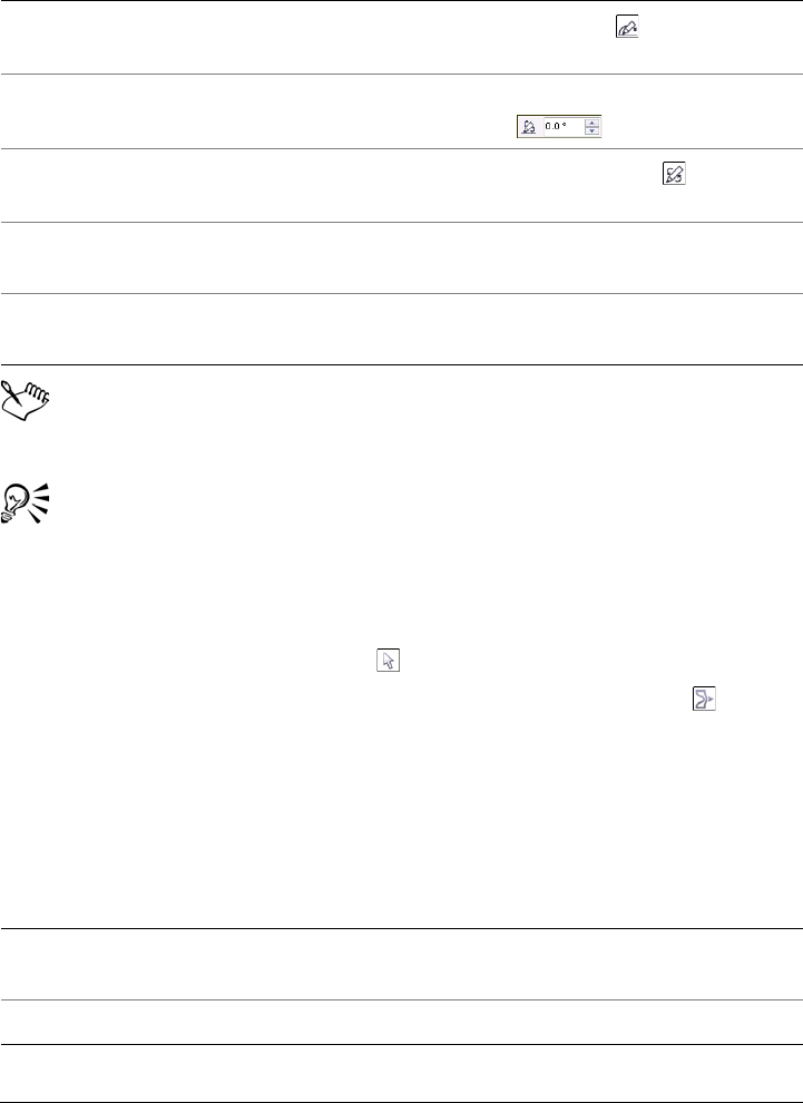
Shaping objects 221
You cannot apply smudging to Internet or embedded objects, linked images,
grids, masks, mesh-filled objects, or objects with blend and contour effects.
To see the minimum and maximum values for the smudging controls, right-
click the control on the property bar and click Settings.
To smear an object
1Select a curve object using Pick tool .
2Click the Shape tools button in the toolbox, and click the Smear tool .
3Do one of the following:
• To smear the outside of an object, click outside an object, close to its edge, and
drag outwards.
• To smear the inside of an object, click inside an object, close to its edge, and drag
inwards.
Change the shape of the smudging when
using a pen tablet
Click the Pen tilt button on the property
bar.
Specify the angle of the nib shape for
smudging
Type a value between 0 and 359 in the
Bearing box on the property bar.
Change the angle of the nib shape for
smudging when using a pen tablet
Click the Pen bearing button on the
property bar.
Smudge the inside of an object Click the outside of an object and drag
inwards.
Smudge the outside of an object Click the inside of an object an drag
outwards.
You can also
Change the radius of the brush nib Type a value in the Nib radius box on the
property bar.
Set the amount of smearing Type a value in the Pressure box.
You can also
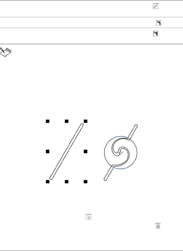
222 Corel DESIGNER X6 User Guide
The difference between a smooth smear and pointy smear is noticeable only
with higher Pressure values.
Adding twirl effects
You can add twirl effects to objects. You can set the radius, speed, and direction of the
twirl effects, and you can use the pressure of your digital pen to change the intensity of
the twirl effect.
Adding a twirl effect
To add a twirl effect to an object
1Select a curve object using Pick tool .
2Click the Shape tools button in the toolbox, and click the Tw i r l tool .
3Click the edge of the object, and hold down the mouse button until the twirl is the
size you want.
Use the pressure of a digital pen to control
the amount of smearing
Click the Pen pressure button on the
property bar.
Use smooth curves when smearing Click the Smooth smear button .
Use curves with sharp corners when
smearing
Click the Pointy smear button .
You can also
Shaping objects 223
To position and reshape the twirl, you can drag while holding down the mouse
button.
Roughening objects
The roughening effect lets you apply a jagged or spiked edge to objects, including lines,
curves, and text. You can control the size, angle, direction, and number of the
indentations, whether you use a pen tablet or a mouse.
The roughening effect is determined by the movements of the stylus (or pressure-
sensitive pen), by fixed settings, or by automatically applying perpendicular spikes to
the line. Tilting the stylus toward and away from the tablet’s surface increases and
decreases the size of the spikes. If you are using a mouse, you can specify a tilt angle
between 0 and 90°. You can determine the direction of the spikes by changing the angle
of rotation (or bearing) of the stylus as you apply the roughening effect to an object.
When you are using a mouse, you can set the bearing angle from 0 to 359°. You can
also increase or decrease the number of spikes that are applied as you drag.
The roughening effect also responds to the pressure of the stylus on the tablet. The more
pressure you apply, the more spikes are created in the roughened area. If you are using
a mouse, you can specify values to simulate the stylus pressure.
You can also change the brush nib size.
You can also
Set the radius of the twirl effect Type a value in the Nib radius box on the
property bar.
Set the rate at which the twirl effect is
applied
Type a value between 1 and 100 in the Rate
box on the property bar.
Set the direction of the twirl effect Click the Counterclockwise twirl
button or the Clockwise twirl
button .
Use the pressure of a digital pen to control
the intensity of the twirl effect
Click the Pen pressure button on the
property bar.
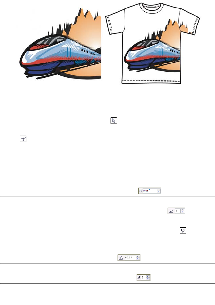
224 Corel DESIGNER X6 User Guide
Roughening allows you to apply jags or spikes to part of an outline or path.
To roughen an object
1Select a curve object using the Pick tool .
2Click the Shape tools button in the toolbox, and click the Roughen brush
tool .
3Point to the area on the outline that you want to roughen, and drag the outline to
distort it.
You can also
Specify the size of the roughening spikes Type a value between 0.01 and 2.0 in the
Nib size box on the property bar.
Change the number of spikes in a roughened
area
Type a value between 1 and 10 in the
Frequency of spikes box on the
property bar.
Change the number of spikes in a roughened
area when using a pen tablet
Click the Pen pressure button on the
property bar.
Specify the height of the roughening spikes Type a value between 0 and 90 in the Tilt
box on the property bar.
Increase the number of roughening spikes as
you drag
Type a value between -10 and 10 in the
Dryout box on the property bar.
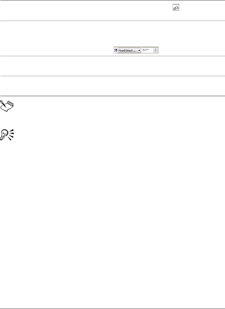
Shaping objects 225
Objects with distortions, envelopes, and perspective applied to them are
converted to curve objects before the roughening effect is applied.
To make the tilt angle and bearing responsive to the stylus, right-click the
roughened object with the Roughen brush tool, and select a command from
the context menu.
To see the minimum and maximum values for the roughening controls, right-
click the control on the property bar, and click Settings.
Shaping objects by attracting or pushing away nodes
The Attract and Repel tools let you shape objects by attracting nodes or pushing nodes
away. To control the shaping effect, you can vary the size of the brush nib and the speed
at which the nodes are attracted or pushed away, and you can use the pressure of your
digital pen.
Change the height of the roughening spikes
when using a pen tablet
Click the Pen tilt button on the property
bar.
Specify the direction of the roughening
spikes
Choose Fixed direction from the Spike
direction list box. Type a value between 0
and 359 in the Pen bearing box
on the property bar.
Change the direction of the roughening
spikes when using a pen tablet
Choose Stylus setting from the Spike
direction list box on the property bar.
Create roughening spikes perpendicular to
the path or outline
Choose Auto from the Spike direction list
box on the property bar.
You can also
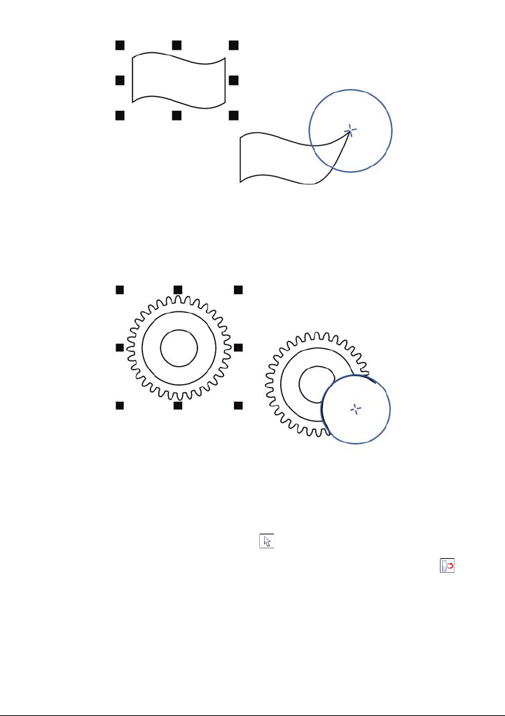
226 Corel DESIGNER X6 User Guide
Using the Attract tool to shape an object
Using the Repel tool to shape an object
To shape an object by attracting nodes
1Select a curve object using the Pick tool .
2Click the Shape tools button in the toolbox, and click the Attract tool .
3Click inside or outside the object, close to its edge, and hold down the mouse
button to reshape the edge. For a more pronounced effect, drag while holding
down the mouse button.
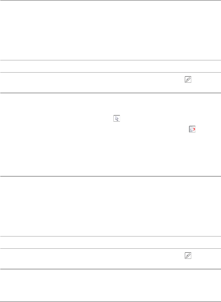
Shaping objects 227
To shape an object by pushing nodes away
1Select a curve object using the Pick tool .
2Click the Shape tools button in the toolbox, and click the Repel tool .
3Click inside or outside the object, close to its edge, and hold down the mouse
button to reshape the edge. For a more pronounced effect, drag while holding
down mouse button.
You can also
Set the radius of the brush nib Type a value in the Nib radius box on the
property bar.
To change the radius of the brush nib, you
can also drag in the document window while
holding down Shift. Drag towards the nib’s
center to decrease the radius, and away from
the nib’s center to increase it.
Set the speed of the attraction Type a value in the Rate box.
Use the pressure of a digital pen to control
the effect
Click the Pen pressure button on the
property bar.
You can also
Set the radius of the brush nib Type a value in the Nib radius box on the
property bar.
To change the radius of the brush nib, you
can also drag in the document window while
holding down Shift. Drag towards the nib’s
center to decrease the radius, and away from
the nib’s center to increase it.
Set the speed of the repel effect Type a value in the Rate box.
Use the pressure of a digital pen to control
the effect
Click the Pen pressure button on the
property bar.

228 Corel DESIGNER X6 User Guide
Applying distortion effects
You can apply three types of distortion effects to shape objects.
After you distort an object, you can change the effect by altering the center of
distortion. This point is identified by a diamond-shaped handle, around which a
distortion appears. It is similar to a mathematical compass, where the pencil moves
around a stationary point. You can place the center of distortion anywhere in the
drawing window, or choose to center it in the middle of an object so that the distortion
is distributed evenly and the shape of the object changes in relation to its center.
You can create an even more dramatic effect by applying a new distortion to an already
distorted object. You don’t lose the effect of the original distortion if, for example, you
apply a zipper distortion on top of a twister distortion. Corel DESIGNER also lets you
remove and copy distortion effects.
To distort an object
1Click the Interactive tools button in the toolbox, and click the Distort tool .
2On the property bar, click one of the following buttons, and specify the settings
you want:
• Push and pull distortion
• Zipper distortion
• Twister distortion
3Point to where you want to place the center of distortion, and drag until the object
is the shape you want.
Distortion effect Description
Push and pull Lets you push the edges of an object in or
pull the edges of an object out.
Zipper Lets you apply a sawtooth effect to the edges
of the object. You can adjust the amplitude
and frequency of the effect.
Twister Lets you rotate an object to create a swirl
effect. You can choose the direction of the
swirl, as well as the origin, degree, and
amount of rotation.
Shaping objects 229
You can reapply the effects to distorted objects.
You can center a distortion by clicking the Center distortion button on the
property bar.
To remove a distortion
1Select a distorted object.
2Click Effects Clear distortion.
Removing a distortion this way clears the most recent distortion you’ve
applied.
You can also remove a distortion from a selected object by clicking the Clear
distortion button on the property bar.
To copy a distortion
1Select the object to which you want to copy a distortion.
2Click Effects Copy effect Distortion from.
3Click a distorted object.
You can also
Change the center of distortion Drag the diamond-shaped position handle to
a new location.
Adjust the number of points on a zipper
distortion
Move the slider on the center of the
distortion handle.
Apply a preset distortion Choose a distortion preset from the Preset
list box on the property bar.
Apply more than one distortion to an object Choose another distortion type on the
property bar, click an object, and drag.

230 Corel DESIGNER X6 User Guide
You can also use the Attributes eyedropper tool to copy the effect. For
more information, see “To copy object properties from one object to another”
on page 253.
Shaping objects by using envelopes
Corel DESIGNER lets you shape objects, including lines, artistic text, and paragraph
text frames by applying envelopes to them. Envelopes are made of multiple nodes that
you can move to shape the envelope and, as a result, change the shape of the object. You
can apply a basic envelope that conforms to the shape of an object, or you can apply a
preset envelope. After you apply an envelope, you can edit it, or add a new envelope to
continue changing the object’s shape. Corel DESIGNER also lets you copy and remove
envelopes.
You can edit an envelope by adding and positioning its nodes. Adding nodes gives you
more control over the shape of the object contained in the envelope. Corel DESIGNER
also lets you delete nodes, move multiple nodes simultaneously, change nodes from one
type to another, and change a segment of an envelope to a line or curve. For more
information about the different types of nodes, see “Working with curve objects” on
page 191.
You can also change the mapping mode of an envelope to specify how the object fits to
the envelope. For example, you can stretch an object to fit the basic dimensions of the
envelope, and then apply the horizontal mapping mode to compress it horizontally so
that it fits the shape of the envelope.
To apply an envelope
1Select an object.
2Click the Interactive tools button in the toolbox, and click the Envelope tool .
3On the property bar, click one of the following buttons:
• Straight line mode — creates envelopes based on straight lines, adding
perspective to objects
• Single-arc mode — creates envelopes with an arc shape on one side, giving
objects a concave or convex appearance
• Double-arc mode — creates envelopes with an S shape on one or more sides
• Unconstrained mode — creates freeform envelopes that let you change the
properties of the nodes, and add or delete nodes
Shaping objects 231
4Click the object.
5Drag the nodes to shape the envelope.
If you want to reset the envelope, press Esc before releasing the mouse button.
You can prevent the object’s straight lines from being converted to curves by
enabling the Keep lines button on the property bar.
To copy an envelope
1Select an object to which you want to copy an envelope.
2Click Effects Copy effect Envelope from.
3Select the object from which you want to copy the envelope.
You can also copy an envelope by selecting an object with the envelope you
want to copy, clicking the Copy envelope properties button on the property
bar when the Envelope tool is active, and selecting the object to which you
want to apply the effect.
To edit an envelope’s nodes and segments
1Click the Interactive tools button in the toolbox, and click the Envelope tool .
2Select an object with an envelope.
3Double-click the envelope to add a node, or double-click a node to delete it.
You can also
Apply a preset envelope Choose an envelope from the Preset list box
on the property bar.
Apply an envelope to an object with an
envelope
Click the Add new envelope button on
the property bar, and drag the nodes to
change the shape of the envelope.
Remove an envelope Click Effects Clear envelope.

232 Corel DESIGNER X6 User Guide
To change the mapping mode
1Click the Interactive tools button in the toolbox, and click the Envelope tool .
2Click an object with an envelope.
3On the property bar, choose one of the following from the Mapping mode list box:
• Horizontal — stretches the object to fit the basic dimensions of the envelope
and then compresses the object horizontally to fit the shape of the envelope
You can also
Move several envelope nodes at once Click the Unconstrained mode button
on the property bar, marquee select the
nodes that you want to move, and drag any
node to a new position.
Marquee select multiple nodes On the property bar, choose Rectangular
from the Selection mode list box, and drag
around the nodes that you want to select.
Freehand marquee select multiple nodes On the property bar, choose Freehand from
the Selection mode list box, and drag
around the nodes that you want to select.
Move opposing nodes an equal distance in
the same direction
Press Shift, select two opposing nodes, and
drag them to a new position.
Move opposing nodes an equal distance in
opposite directions
Click the Single-arc mode or Double-
arc mode button on the property bar,
hold down Shift, and drag one of the nodes
to a new position.
Change an envelope node type Click the Unconstrained mode button on
the property bar, and click the Cusp node
, Smooth node , or Symmetrical
node button.
Change an envelope segment to a straight
line or curve
Click the Unconstrained mode button on
the property bar, click a line segment, and
click the Convert to line button or the
Convert to curve button .

Shaping objects 233
• Original — maps the corner handles of the object’s selection box to the
envelope’s corner nodes. The other nodes are mapped linearly along the edge of
the object’s selection box.
• Putty — maps the corner handles of the object’s selection box to the envelope’s
corner nodes
• Vertical — stretches the object to fit the basic dimensions of the envelope and
then compresses the object vertically to fit the shape of the envelope
4Drag the nodes or the nodes’ control points.
You can’t change the mapping mode of paragraph text frames to which you’ve
applied an envelope.
Reference: Shaping objects
Objects created in Corel DESIGNER follow a path that gives them their defining shape.
When this path is broken or cut, subpaths remain.
Paths and subpaths
• Paths outline an object’s shape and are often visible as one or more line or curve
segments. You can disconnect line segments from one another to create subpaths.
Even though they are not connected, subpaths are still part of the defining path of
the original object; however, you can extract a subpath to create two separate
objects: the extracted subpath and the object it was extracted from.
• Subpaths are the basic curves and shapes from which a single curve object is
constructed. For example, a single curve object with subpaths is often created when
text is converted to curves. The letter “O,” for instance, is composed of two ellipses:
the outside ellipse that defines the letter’s shape and the inside ellipse that defines
the “hole.” The ellipses are subpaths that compose the single curve object, “O”.
One of the basic reasons for creating an object with subpaths is that you can
produce objects with holes in them.

234 Corel DESIGNER X6 User Guide
1) The letter “O” is converted to curves. 2) The resulting subpaths are the
outside ellipse that defines the shape of the letter and the inside ellipse (tinted
gray) that defines the hole. 3) In comparison, the black ellipse consists of a
single path and cannot contain a “hole.”
31 2

Projecting objects 235
Projecting objects
The Corel DESIGNER application lets you work in projected drawing modes. You can
use drawing profiles to project objects onto drawing planes and create the illusion of a
three-dimensional image.
This section contains the following topics:
• Understanding projected drawing modes
• Using projected drawing modes
• Customizing drawing profiles
Understanding projected drawing modes
Corel DESIGNER provides preset drawing profiles for working in projected drawing
modes. After choosing a drawing profile, you then draw or project objects onto its three
drawing planes (top, front, and right) to create the illusion of a three-dimensional
image. When you close your drawing, the last drawing profile you used is saved along
with it; this drawing profile is automatically activated the next time you open the file.
Corel DESIGNER provides 11 preset drawing profiles:
•one isometric (default)
•four dimetric
•four trimetric
• one cavalier oblique
• one cabinet oblique
You can choose a different drawing profile at any time; however, if you change drawing
profiles after you have begun a project, the geometry of your existing objects will not
change.
If the preset drawing profiles do not meet your needs, you can create new ones or edit
existing ones. For more information, see “Customizing drawing profiles” on page 240.
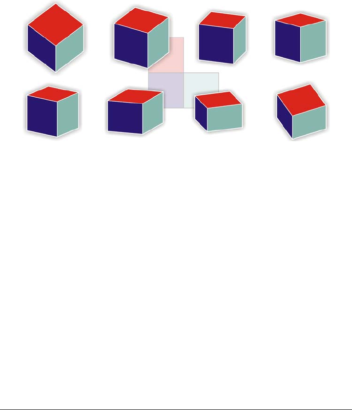
236 Corel DESIGNER X6 User Guide
Each default drawing profile is associated with a set of three numbers, which correspond
to the x, y, and z axes, respectively. The x-axis is measured in degrees, clockwise from a
line perpendicular to the y-axis. The y-axis is measured in degrees, counterclockwise
from the true horizontal, which is 0° east. The z-axis is measured in degrees,
counterclockwise from a line perpendicular to the y-axis. The isometric drawing profile,
for example, has measurements of (30,90,30) while the cavalier oblique drawing profile
has measurements of (0,90,45).
This image depicts a cube displayed by using eight different drawing profiles.
Top row, left to right: Dimetric (37,90,37); Dimetric (16,90,37);
Dimetric (7,90,42); Dimetric (15,90,15).
Bottom row, left to right: Tr i m e t r i c (12,90,23); Tr i m e t r i c (5,90,30);
Tr i m e t r i c (45,90,7); Tr i m e t r i c (54,90,17)
You can choose to work from one of four drawing planes:
• orthographic — draws on a flat plane, such as the top, front, or right drawing
plane
• top — draws onto a projected plane bounded by the x and z axes defined in the
drawing profile
• front — draws onto a projected plane bounded by the x and y axes defined in the
drawing profile
• right — draws onto a projected plane bounded by the y and z axes defined in the
drawing profile
The default drawing plane is orthographic. Although you can change drawing planes at
any time, only one drawing plane can be active at a time.
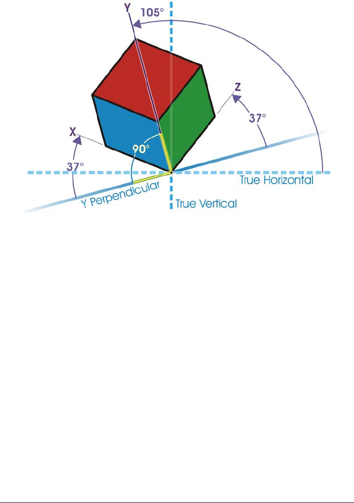
Projecting objects 237
In this example, a drawing profile is depicted. The x-axis is 37° clockwise
from a line perpendicular to the y-axis. The y-axis is 105° counterclockwise
from the true horizontal. The z-axis is 37° counterclockwise from a line
perpendicular to the y-axis. Therefore, the drawing profile has a value of
(37,105, 37).
Using projected drawing modes
You can specify a projected drawing mode by choosing drawing profiles and drawing
planes from the Drawing plane toolbar. However, you can have only one drawing
profile and one drawing plane active at a time.
You can draw an object in a projected drawing mode, or you can project an object onto
a drawing plane. You can also unproject an object from a drawing plane; this
reconstructs the object as it would appear in an orthographic view.
To display or hide the Drawing Plane toolbar
•Click View To o l b a r s Drawing plane.
A check mark beside the Drawing plane command indicates that the Drawing
plane toolbar is displayed.
238 Corel DESIGNER X6 User Guide
To choose a preset drawing profile
•From the Drawing profiles list box on the Drawing plane toolbar, choose one of
the following preset drawing profiles:
• Cabinet oblique (0, 90, 60)
• Cavalier oblique (0,90,45)
• Dimetric (37,90,37)
• Dimetric (16,90,37)
• Dimetric (7,90,42)
• Dimetric (15,90,15)
• Isometric (30,90,30)
• Trimetric (12,90,23)
• Tr i m e t r i c ( 5 , 9 0 , 3 0 )
• Trimetric (45,90,7)
• Trimetric (54,90,17)
To choose a drawing plane
•On the Drawing plane toolbar, choose one of the following drawing planes:
• Orthographic
• To p
• Front
• Right
To draw an object in a projected drawing mode
1From the Drawing profiles list box on the Drawing plane toolbar, choose a
drawing profile.
2On the Drawing plane toolbar, choose the To p , Front, or Right drawing plane.
3Draw an object.
To project an object onto a drawing plane
1Select an object.
2Click Arrange Tr a n s f o r m a t i o n s Project.
3In the Tr a n s f o r m a t i o n s docker, choose Project from the list box.
4In the Plane area, click one of the following buttons:
• To p — projects the object onto the top plane
• Front — projects the object onto the front plane

Projecting objects 239
• Right — projects the object onto the right plane
5To specify an origin point on the drawing around which to project the selected
object, do one of the following:
• Type values in the X and Y boxes to specify coordinates along the horizontal and
vertical axes.
• Click the Specify point button next to the X and Y boxes, and click a point
on the drawing.
• Enable the Relative origin check box, and click the point on the origin locator
that corresponds to the point on the object from which you want to project
the object.
If you want to leave the original object unchanged and apply the transformation to
a copy, type 1 in the Copies box. The number of copies cannot exceed one.
6Click Apply.
Applying a contour to a projected object may not produce the desired results.
It is recommended that you apply a contour to the object in its unprojected
state and then project the object. Contour groups can be unlinked by clicking
Arrange Break contour group apart.
To unproject an object from a drawing plane
1Select an object.
2Click Arrange Tr a n s f o r m a t i o n s Project.
3In the Tr a n s f o r m a t i o n s docker, choose Unproject from the list box.
4In the Plane area, click one of the following buttons:
• To p — unprojects the object from the top plane
• Front — unprojects the object from the front plane
• Right — unprojects the object from the right plane
5To specify an origin point in the drawing around which to unproject the selected
object, do one of the following:
• Type values in the X and Y boxes to specify coordinates along the horizontal and
vertical axes.
• Click the Specify point button next to the X and Y boxes, and click a point
on the drawing.

240 Corel DESIGNER X6 User Guide
• Enable the Relative origin check box, and click the point on the origin
locator that corresponds to the point on the object from which you want to
unproject the object.
If you want to leave the original object unchanged and apply the transformation to
a copy, type 1 in the Copies box. The number of copies cannot exceed one.
6Click Apply.
Customizing drawing profiles
You can use the Projected axes docker to create and edit drawing profiles. The
Projected axes docker features a real-time preview of a cube, which represents the
projected axes and scales for the chosen drawing profile. When you change drawing
profiles, or when you modify the projected axes or scales, the preview is automatically
updated.
The Projected axes docker allows you to set the degree offsets for the x, y, and z axes.
For information on how these offsets are calculated, see “Understanding projected
drawing modes” on page 235. The Projected axes docker also allows you to set a scale
factor for each axis. For example, if you use a drawing profile with a scale of 50% on the
x-axis, projected objects will display at half their original size along their x-axis.
You can create a customized drawing profile from an existing one. You can also edit
preset and custom drawing profiles, or you can delete them altogether.
To display or hide the Projected Axes docker
•Click Window Projected axes.
A check mark beside the Projected axes command indicates that the Projected
axes docker is displayed.
To create or edit a drawing profile
1If the Projected axes docker is hidden, click Window Projected axes to display
it.
If you want to edit a drawing profile, choose a profile from the list.
2In the Projected axes docker, do one of the following:
• Enter a value between -360 and 360 in the X axis angle box. Repeat for the y
and z axes.

Projecting objects 241
• Click the User specified angle button next to the Angle box, and drag the
pointer in the drawing window.
3Enter a value between 10 and 500 in the X axis scale box. Repeat for the y and z
axes.
4Click the Save button .
5Choose where you want to save the file, and type a filename in the Filename box.
6Click Save.
You can create a custom axonometric drawing profile by having the application
calculate the scale values automatically. To do this, type values in the X axis
angle, Y axis angle, and Z axis angle boxes, and enable the Auto
axonometric check box. Note that the Auto axonometric check box may be
disabled for some angle values. In such cases, you first need to adjust the angle
values so that the option becomes available.
To delete a drawing profile
1In the Projected axes docker, choose a drawing profile from the list box.
2Click the Delete button .

Objects, symbols, and layers 243
Objects, symbols, and layers
Working with objects . . . . . . . . . . . . . . . . . . . . . . . . . . . . . . . . . . . . . . .245
Working with symbols . . . . . . . . . . . . . . . . . . . . . . . . . . . . . . . . . . . . . .277
Creating objects for the Web . . . . . . . . . . . . . . . . . . . . . . . . . . . . . . . . .289
Working with layers . . . . . . . . . . . . . . . . . . . . . . . . . . . . . . . . . . . . . . . .305
Object linking and embedding . . . . . . . . . . . . . . . . . . . . . . . . . . . . . . . .315
Working with object data . . . . . . . . . . . . . . . . . . . . . . . . . . . . . . . . . . . .319

Working with objects 245
Working with objects
Working with objects is an essential part of creating drawings.
This section contains the following topics:
• Selecting objects
• Changing object properties
• Copying, duplicating, and deleting objects
• Copying object properties, transformations, and effects
•Cloning objects
• Moving objects
• Sizing and scaling objects
• Rotating objects
• Mirroring objects
• Skewing objects
• Aligning and distributing objects
• Changing the order of objects
• Grouping objects
• Combining objects
•Locking objects
• Finding and replacing objects
• Accessing and displaying geometric information about objects
•Inserting bar codes
Selecting objects
Before you can change an object, you must select it. You can select visible objects,
hidden objects, a single object in a group or a nested group, and each object in the order
in which it was created. You can also select all objects simultaneously and deselect
objects.
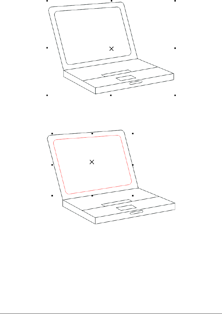
246 Corel DESIGNER X6 User Guide
A selection box appears around a selected object, and an “X” appears at its
center.
You can select a single object in a group.
You can select all objects using the Pick tool. However, some tools allow you to select
only objects that are appropriate to the active tool. For example, if a curve tool is active,
you can select any curve object, but you cannot select other object types.
When you select an object, either a selection box, rotation and skew handles, or the
object’s nodes appear. Clicking a selected object changes its selection mode. The
selection modes are
•Drag and scale — a selection box appears around the object.

Working with objects 247
•Rotate and skew — rotation and skew handles appear around the object.
•Shape/Edit — the object’s nodes appear.
You can drag, rotate, or shape the object by its snap points, depending on which
selection mode is active. See “Using gravity snapping” on page 101 for a list of snap
points.
To select objects
To select Do the following
An object Click the object using the Pick tool .
Multiple objects Hold down Shift, and click each object that
you want to select.
Multiple objects by using a marquee
selection area of irregular shape
Click the Freehand pick tool , and drag
around the objects that you want to select.
Objects that are only partially enclosed by
the selection area are not selected.
To select objects that are only partially
enclosed by the selection area, hold down Alt
while dragging.
To constrain the selection area to a
rectangular shape, hold down Ctrl while
dragging.
An object, starting with the first object
created and moving toward the last object
created
Press Shift + Ta b until a selection box
appears around the object that you want to
select.
An object, starting with the last object
created and moving toward the first object
created
Press Ta b until a selection box appears
around the object that you want to select.
All objects Press Ctrl + A.
Or click Edit Select all Objects.
An object in a group Hold down Ctrl, and click an object in a
group.
248 Corel DESIGNER X6 User Guide
The status bar displays a description of each object as you select it.
You can also select one or more objects by dragging around the object or
objects using the Pick tool. This method is called “marquee select.”
If you hold down Alt while dragging, any objects you intersect are also
selected.
To deselect objects
An object in a nested group Hold down Ctrl, and click the object that
you want to select until a selection box
appears around it.
A hidden object Hold down Alt, and click the topmost object
until a selection box appears around the
hidden object that you want to select.
Multiple hidden objects Hold down Shift + Alt, and click the
topmost object until a selection box appears
around the hidden objects that you want to
select.
A hidden object in a group Hold down Ctrl + Alt, and click the
topmost object until a selection box appears
around the hidden object that you want to
select.
To deselect Do the following
All objects Press Esc.
Or click the Pick tool , and click a blank
space in the drawing window.
A single object in multiple selected objects Hold down Shift, and click the object using
the Pick tool.
To select Do the following

Working with objects 249
Changing object properties
After you’ve created an object, you can change its properties. There are several ways to
do this, including using the property bar, color palette, and dialog boxes. For more
information about changing the default properties for new objects, see “Setting the
default property values” on page 133.
In addition, you can copy object properties such as outline, fill, and text properties from
one object to another. For more information, see “Copying object properties,
transformations, and effects” on page 253.
Copying, duplicating, and deleting objects
Corel DESIGNER provides you with several ways to copy objects. When you no longer
need an object, you can delete it.
Cutting, copying, and pasting
You can cut or copy an object to place it on the Clipboard and paste it into a drawing
or another application. Cutting an object places it on the Clipboard and removes it from
the drawing. Copying an object places it on the Clipboard but keeps the original in the
drawing.
Duplicating
Duplicating an object places a copy directly in the drawing window and does not use
the Clipboard. Duplicating is faster than copying and pasting. Also, when duplicating
an object, you can specify the distance between the duplicate and the original object
along the x and y axes. This distance is known as the offset.

250 Corel DESIGNER X6 User Guide
Duplicate offset
Copying objects at a specified position
You can create multiple copies of objects simultaneously, while specifying their position,
without using the Clipboard. For example, you can distribute object copies horizontally,
to the left or right of the original object; or you can distribute copies of objects vertically,
below or above the original object. You can specify the spacing between copies of
objects, or you can specify the offset at which copies of objects are created in relation to
each other.
To cut or copy an object
1Select an object.
2Click Edit, and click one of the following:
• Cut
• Copy
You can also cut or copy an object by right-clicking the object and clicking Cut
or Copy.
To paste an object into a drawing
•Click Edit Paste.

Working with objects 251
To duplicate an object
1Select an object.
2Click Edit Duplicate.
The duplicate is placed at an offset from the original object.
When you duplicate objects for the first time, the Duplicate offset dialog box
appears. To specify the distance between the duplicate and the original object along
the x and y axes, type values in the Horizontal offset and Vertical offset boxes.
• Offset values of 0 place the duplicate on top of the original.
• Positive offset values place the duplicate up and to the right of the original.
• Negative offset values place the duplicate down and to the left of the original.
If you’ve set the Ctrl and Shift keys to the Windows standard
(Ctrl=Duplicate/Leave original, Shift=Constrain), you can duplicate an
object as you place the duplicate where you want in the drawing window. To
do this, first select the object using the Pick tool . Holding down Ctrl, drag
the object to where you want to create a duplicate, and release the mouse
button. For information about setting the Ctrl and Shift keys to the Windows
standard, see “To change the constrain key” on page 118.
You can also duplicate a selected object by pressing Ctrl + D.
You can change the offset at which duplicates are created. Click To o l s
Options. In the Document list of categories, click General, and type values
in the Horizontal and Vertical boxes in the Duplicate offset area.
To delete an object
1Select an object.
2Click Edit Delete.
You can also delete an object by clicking the object and pressing Delete.
To create copies of an object at a specified position
1Select an object.
2Click Edit Step and repeat.
3In the Step and repeat docker, type a value in the Number of copies box.
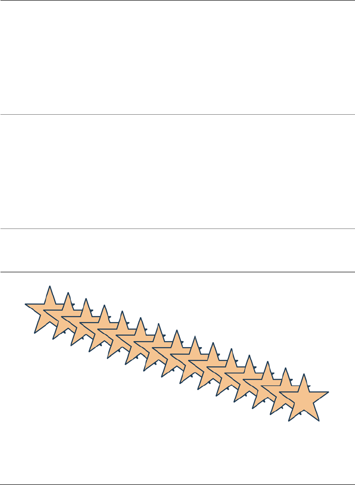
252 Corel DESIGNER X6 User Guide
Multiple copies of an object are offset by a specified distance.
To Do the following
Distribute copies of objects horizontally In the Vertical settings area, choose No
offset from the Mode list box. In the
Horizontal offset area, choose Spacing
between objects from the Mode list box. To
specify the spacing between object copies,
type a value in the Distance box. To place
the object copies to the right or left of the
original, choose Right or Left from the
Direction list box.
Distribute copies of objects vertically In the Horizontal settings area, choose No
offset from the Mode list box. In the
Vertical offset area, choose Spacing
between objects from the Mode list box. To
specify the spacing between copies of objects,
type a value in the Distance box. To place
the copies above or below the original,
choose Up or Down from the Direction list
box.
Offset all copies of objects by a specified
distance
In the Horizontal offset and Vertica l offset
areas, choose Offset from the Mode list box,
and type values in the Distance boxes.

Working with objects 253
Copying object properties, transformations, and effects
You can copy object properties such as outline, fill, and text properties from one object
to another. You can copy object transformations such as sizing, rotating, and positioning
as well as effects applied to an object.
To copy object properties from one object to another
1Click the Eyedropper tools button, and click the Attributes eyedropper tool .
2Click Properties on the property bar, and enable any of the following check boxes:
• Outline
• Fill
• Te x t
3Click the edge of the object whose properties you want to copy.
The Attributes eyedropper tool automatically switches to the Apply object
attributes mode.
4Click the edge of the object to which you want to apply the copied properties.
Any Tr a n s f o r m a t i o n s and Effects options on the property bar that are
enabled are also applied when you copy properties.
You can also copy fill or outline properties, or both, by right-clicking an object
with the Pick tool , dragging over another object, and choosing Copy fill
here, Copy outline here, or Copy all properties.
You can also copy object properties to a selected object by clicking Edit Copy
properties from and clicking the object whose properties you want to copy.
To copy size, position, or rotation from one object to another
1Click the Eyedropper tools button, and click the Attributes eyedropper tool .
2Click Tr a n s f o r m a t i o n s on the property bar, and enable any of the following check
boxes:
• Size
• Rotation
• Position
3Click the edge of the object whose transformations you want to copy.

254 Corel DESIGNER X6 User Guide
The Attributes eyedropper tool automatically switches to the Apply object
attributes mode.
4Click the edge of the object to which you want to apply the copied transformations.
Any Properties and Effects options on the property bar that are enabled are
also applied when you copy properties.
To copy effects from one object to another
1Click the Eyedropper tools button, and click the Attributes eyedropper tool .
2Click Effects on the property bar, and enable any of the following check boxes:
• Perspective
• Envelope
• Blend
• Extrude
• Contour
• Lens
• PowerClip
• Drop shadow
• Distortion
3Click the edge of the object whose effects you want to copy.
The Attributes eyedropper tool automatically switches to the Apply object
attributes mode.
4Click the edge of the object to which you want to apply the copied effects.
Any Properties and Tr a n s f o r m a t i o n s options on the property bar that are
enabled are also applied when you copy properties.
Cloning objects
When you clone an object, you create a copy of an object that is linked to the original.
Any changes you make to the original object are reflected automatically in the clone.
Changes you make to the clone are not automatically reflected in the original, however.
You can remove changes made to the clone by reverting to the original.
Cloning lets you modify multiple copies of an object simultaneously by changing the
master object. This type of modification is especially useful if you want the clone and
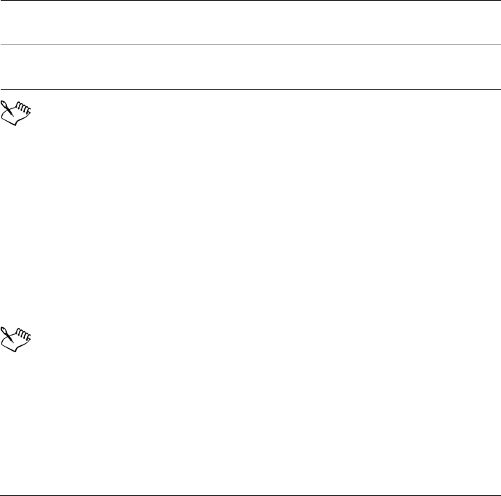
Working with objects 255
master objects to differ by certain properties, such as fill and outline color, but the
master object to control other properties, such as shape.
If you simply want to use the same object in a drawing multiple times, consider using
symbols, instead of clones, to keep the file size manageable. For more information about
symbols, see “Working with symbols” on page 277.
To clone an object
1Select an object.
2Click Edit Clone.
You can clone a master object multiple times, but you cannot clone a clone.
To revert to the master object of a clone
1Right-click a modified clone, and click Revert to master.
2Enable any of the following check boxes:
• Clone fill — restores the master fill attributes
• Clone outline — restores the master outline attributes
• Clone path shape — restores the master shape attributes
• Clone transformations — restores the master shape and size attributes
• Clone bitmap color mask — restores the master color settings
Only the clone properties that are different from the master object are available
in the Revert to master dialog box.
Moving objects
You can move objects by dragging, by specifying distance and direction, or by nudging.
You can also move an object while you are drawing it.
You can also
Select the master object of a clone Right-click the clone, and click Select
master.
Select the clone objects of a master Right-click the master, and click Select
clones.

256 Corel DESIGNER X6 User Guide
Super nudging and micro nudging let you move objects into place by increments. By
default, you can nudge objects in 0.01-inch increments, but you can change the nudge
values to suit your needs.
To move an object
1Select an object.
2Click Arrange Tr a n s f o r m a t i o n s Position.
The Tr a n s f o r m a t i o n s docker appears.
3Use one of the following methods:
• Horizontal and vertical — type the horizontal and vertical values to move the
object
• Length and angle — type the distance and angle to move the object
• Set distance interactively — click the Set position interactively button ,
and drag the pointer in the drawing window to specify the distance and angle to
move the object
• Gap and direction — enable the second option in the docker, type a value for
the gap, and choose the direction to move the object. This option moves the
object in the selected direction at a distance equal to the height or width of its
bounding box plus the specified gap.
If you want to leave the original object unchanged and apply the transformation to
copies that are created, type a number in the Copies box.
4Click Apply.
By default, the point of origin (0,0) is at the lower-left corner of the drawing
page. When you enable the Relative position check box in the
Tr a n s f o r m a t i o n s docker, the position of the center anchor point of the object,
and not the point of origin of the drawing page, is identified as 0,0 in the H
and V boxes. When you specify a different position in the H and V boxes, the
values represent a change from the current position as measured from the
center anchor point of the object.
You can also move a selected object by dragging it to another position in the
drawing.
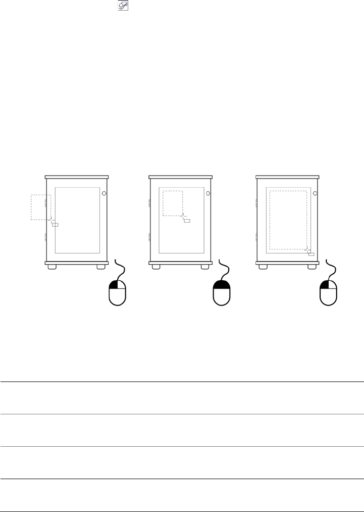
Working with objects 257
You can set a precise location for the object by clicking the Geometric
properties button on the property bar and typing values in the Property
manager docker.
You can use snapping to move an object with precision. For more information,
see “Working with precision” on page 101.
To move an object while drawing
1Start drawing an object.
2Hold down the right mouse button without releasing the left mouse button, and
drag the unfinished object to its new position.
3Release the right mouse button, and continue drawing.
Moving an object while drawing
To nudge an object
To Do the following
Nudge a selected object by the nudge
distance
Press an Arrow key.
Nudge a selected object by a fraction of the
nudge distance (Micro nudge)
Hold down Ctrl, and press an Arrow key.
Nudge a selected object by a multiple of the
nudge distance (Super nudge)
Hold down Shift, and press an Arrow key.

258 Corel DESIGNER X6 User Guide
To set nudge distances
1Click To o l s Options.
2In the Document list of categories, click Rulers.
3Type a value in the Nudge box.
4Type a value in one of the following boxes:
• Super nudge
• Micro nudge
You can also set the nudge distance by deselecting all objects and typing a
value in the Nudge distance box on the property bar.
To save the new nudge distances to use in new drawings, click To o l s Save
settings as default.
Sizing and scaling objects
Corel DESIGNER lets you size and scale objects. In both cases, you can change the
dimensions of an object proportionally by preserving its aspect ratio. You can size an
object by specifying values or changing the object interactively. Scaling changes an
object’s dimensions by a specified percentage.
Objects are sized or scaled from the object’s origin. You can change an object’s origin
from its center to any one of its eight selection handles.
You can also specify a rectangular area for selected objects to scale into.
To specify the size of an object
1Select an object.
2Click View To o l b a r s Tr a n s f o r m .
3Type values in the Object size boxes on the Tr a n s f or m toolbar.
You can also
Apply the sizing according to the object’s
position rather than the x and y coordinates
Click the Relative to object button on
the Tr a n s f o r m toolbar.

Working with objects 259
To size an object interactively
You can set a precise size for the object by clicking the Geometric properties
button on the property bar and typing values in the Property manager
docker.
To scale an object
1Select an object.
2Click the Shape tools button in the toolbox, and click the Free transform tool .
Size an object by using the Tr a n s f o r m a t i o n s
docker
Clicking Arrange Tr a n s f o r m a t i o n s
Size, and type values in the X and Y boxes
to set the width and height of the object.
Preserve the original ratio of width to height
when transforming the object
In the Tr a n s f o r m a t i o n s docker, enable the
Proportional check box.
Size from a point on the selected object In the Tr a n s f o r m a t i o n s docker, click the
point on the origin locator that
corresponds to the point on the object from
which you want to size the object.
Leave the original object unchanged and
apply the transformation to copies that are
created
In the Tr a n s f o r m a t i o n s docker, type a
number in the Copies box.
To Do the following
Size a selected object Drag any of the corner selection handles.
Size a selected object from its center Hold down Shift, and drag one of the
selection handles.
Size a selected object to a multiple of its
original size
Hold down Ctrl, and drag one of the
selection handles.
Stretch a selected object as you size it Hold down Alt, and drag one of the
selection handles.
You can also

260 Corel DESIGNER X6 User Guide
3Click the Free scale button on the property bar.
If you want to change the reference point to use when scaling the object, locate the
Object origin icon on the property bar and click the box that corresponds to
the reference point you want to set.
4On the property bar, type values in the Scale factor boxes to specify a percentage
by which to scale the object horizontally or vertically.
If you want to maintain the aspect ratio, click the Lock ratio button on the
property bar.
You can also scale an object by dragging a selection handle.
You can also scale an object by typing values in the Scale factor boxes on the
Tr a n s f o r m toolbar. To display the Tr a n s f o r m toolbar, click View To o l b a r s
Tr a n s f o r m .
You can also
Apply the scaling according to the object’s
position rather than the x and y coordinates
Click the Relative to object button on
the Tr a n s f o r m toolbar.
To open the Tr a n s f o r m toolbar, click View
Toolbars Tr a n s f o r m .
Scale an object by using the
Transformations docker
Click Arrange Transformations Scale
and mirror, and type values in the X and Y
boxes to scale the object horizontally or
vertically.
Specify a rectangular area into which to scale
the object
In the Tr a n s f o r m a t i o n s docker, enable the
Fit to box option.
Preserve the original ratio of width to height
when transforming the object
In the Tr a n s f o r m a t i o n s docker, enable the
Proportional check box.
Scale from a point on the selected object In the Tr a n s f o r m a t i o n s docker, click the
point on the origin locator that
corresponds to the point on the object from
which you want to scale the object.
Leave the original object unchanged and
apply the transformation to copies that are
created
In the Tr a n s f o r m a t i o n s docker, type a
number in the Copies box.
Working with objects 261
Rotating objects
You can rotate an object in a drawing by specifying an angle of rotation. You can also
specify a point on the drawing around which to rotate, or rotate around a point on the
selected object.
To rotate an object
1Select an object.
2Click the Shape tools button in the toolbox, and click the Free transform tool .
3Click the Free rotation button on the property bar.
If you want to change the reference point to use when rotating the object, locate
the Object origin icon on the property bar and click the box that corresponds
to the reference point you want to set.
4Type a value in the Angle of rotation box on the property bar.
To specify a point on the drawing to rotate around, type coordinates in the Center
of rotation boxes on the property bar.
You can also
Apply the rotation according to the object’s
position rather than the x and y coordinates
Click the Relative to object button on
the Tr a n s f o r m toolbar.
To open the Tr a n s f o r m toolbar, click View
Toolbars Tr a n s f o r m .
Rotate an object using the Transformations
docker
Click Arrange Transformations
Rotate.
Specify two points for the angle by dragging In the Tr a n s f o r m a t i o n s docker, click the
Rotation angle button next to the
Angle of rotation box, and drag in the
drawing window.
Specify a point on the drawing to rotate
around by clicking
In the Tr a n s f o r m a t i o n s docker, click the
Specify point button next to the X and
Y boxes, and click a point on the drawing.
262 Corel DESIGNER X6 User Guide
You can also rotate a selected object by dragging a rotation handle
clockwise or counterclockwise.
You can also rotate an object by typing a value in the Angle of rotation box
on the Tr a n s f o r m toolbar. To display the Tr a n s f o r m toolbar, click View
To o l b a r s Tr a n s f o r m .
Mirroring objects
With Corel DESIGNER, you can create mirror images of objects. Mirroring an object
flips it from left to right or top to bottom. By default, the anchor point is in the center
of the object.
To mirror an object
1Select an object.
2Click Arrange Tr a n s f o r m a t i o n s Scale and mirror.
3In the Tr a n s f o r m a t i o n s docker, enable the Mirror horizontally option or the
Mirror vertically option .
4In the Tr a n s f o r m a t i o n s docker, click the point on the origin locator that
corresponds to the point on the object about which you want to mirror the object.
Rotate around a point on the selected object In the Center area of the Transformations
docker, enable the Relative center check
box, and click the point on the origin locator
that corresponds to the center of rotation
that you want to set.
Adjust the object orientation when rotating In the Tr a n s f o r m a t i o n s docker, enable the
Rotate orientation option .
Keep the object orientation when rotating In the Tr a n s f o r m a t i o n s docker, enable the
Retain orientation option .
Leave the original object unchanged and
apply the transformation to a copy
In the Tr a n s f o r m a t i o n s docker, type a
number in the Copies box.
You can also
Working with objects 263
To leave the original object unchanged and apply the transformation to a copy, type
1 in the Copies box in the Tr a n s f o r m a t i o n s docker.
5Click Apply.
You can also mirror a selected object by holding down Ctrl and dragging a
selection handle to the opposite side of the object.
Skewing objects
When you skew an object, you slant it horizontally, vertically, or both. You can specify
the degree by which you want to slant the object. You can also change the skew and
sizing anchor point of an object from its default center position.
To skew an object
1Select an object.
2Click the Shape tools button in the toolbox, and click the Free transform tool .
3Click the Free skew button on the property bar.
If you want to change the object’s reference point to use when skewing the object,
locate the Object origin icon on the property bar and click the box that
corresponds to the reference point you want to set.
4Type values in the Skew angle boxes on the property bar.
You can also
Apply the skewing according to the object’s
position rather than the x and y coordinates
Click the Relative to object button on
the property bar.
Skew an object using the Transformations
docker
Click Arrange Tr a n s f o r m a t i o n s Skew,
and type values in the X and Y boxes to
skew the object horizontally or vertically.
Skew from a point on the selected object In the Tr a n s f o r m a t i o n s docker, enable the
Use anchor point check box, and click the
point on the origin locator that
corresponds to the point on the object from
which you want to skew the object.

264 Corel DESIGNER X6 User Guide
If you move the skew anchor point, you can reset it to the center again by
clicking Arrange Clear transformations.
You can also skew an object interactively by dragging one of its skew handles.
You can also skew an object by typing values in the Skew angle boxes on the
Tr a n s f o r m toolbar. To display the Tr a n s f o r m toolbar, click View To o l b a r s
Tr a n s f o r m .
Aligning and distributing objects
Corel DESIGNER lets you precisely align and distribute objects in a drawing. You can
instantly view the effect of changes as you modify the options in the Align and
distribute docker. By default, objects are aligned and distributed based on their paths.
You can also align and distribute objects from the edge of their outlines.
You can align objects to each other or to parts of the drawing page such as the center,
edges, and grid. When you align objects to objects, you can line them up by their
centers or by their edges. You can also align objects with a reference point by specifying
its exact x and y coordinates.
Corel DESIGNER lets you align multiple objects to the center of the drawing page
horizontally or vertically.
You can distribute objects at equal intervals in a specified area.
Leave the original object unchanged and
apply the transformation to a copy
In the Tr a n s f o r m a t i o n s docker, type a
number in the Copies box.
You can also
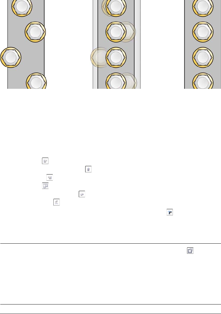
Working with objects 265
Example of aligning objects to each one’s center
To align objects
1Select the objects.
2Click Arrange Align and distribute Align and distribute.
3In the Align area of the docker, click one of the following buttons to use an object
edge or center for aligning.
• Align left — to align the left edges of objects
• Align center horizontally — to align object centers along a vertical axis
• Align right — to align the right edges of objects
• Align top — to align the top edges of objects
• Align center vertically — to align object centers along a horizontal axis
• Align bottom — to align the bottom edges of objects
To align objects from their outlines, click the Outline button .
4In the Align objects to area, perform any of the following tasks.
To Do the following
Align an object with a specific object Click the Active objects button .
If you select the objects one at a time, the
last object selected is the reference point for
aligning the other objects. If you marquee
select the objects, the object that is
positioned in the upper-left corner of the
selection is used as a reference point.
266 Corel DESIGNER X6 User Guide
You can also align objects with another object quickly, without using the Align
and distribute docker, by clicking Arrange Align and distribute and
clicking any of the first six alignment commands. The letter next to a
command name indicates the keyboard shortcut that you can use to align
objects. For example, the letter L next to the Align left command shows that
you can press L to align objects with the leftmost point of the object that is used
as a reference point.
You can use snapping to precisely specify the alignment point. For more
information, see “Working with precision” on page 101.
Align an object with the page edge Click the Page edge button .
Align an object with the page center Click the Page center button .
To align the center of the object with the
page center, make sure that the Align
center horizontally button and Align
center vertically button in the Align
area are enabled.
Align an object with the closest grid line Click the Grid button .
Align an object with a specified point Click the Specified point button , and
type values in the Specify coordinates
boxes.
You can also specify a point interactively by
clicking the Specify point button and
clicking in the document window.
Set an alignment option for text objects In the Te x t area, choose one of the following
options:
•First line baseline — aligns text by the
baseline of the first line
•Last line baseline — aligns text by the
baseline of the last line
•Bounding box — aligns text by its
bounding box
To Do the following
Working with objects 267
To distribute objects
1Select the objects.
2Click Arrange Align and distribute Align and distribute.
3To distribute objects horizontally, click one of the following buttons:
• Distribute left — evenly spaces the left edges of the objects
• Distribute center horizontally — evenly spaces the center points of the
objects along a horizontal axis
• Distribute right — evenly spaces the right edges of the objects
• Distribute space horizontally — places equal intervals between the objects
along a horizontal axis
4To distribute objects vertically, click one of the following buttons:
• Distribute top — evenly spaces the top edges of the objects
• Distribute center vertically — evenly spaces the center points of the objects
along a vertical axis
• Distribute bottom — evenly spaces the bottom edges of the objects
• Distribute space vertically — places equal intervals between the objects
along a vertical axis
5To choose the area over which the objects are distributed, click one of the following
buttons in the Distribute objects to area:
• Extent of selection — distributes the objects over the area of the bounding
box surrounding them
• Extent of page — distributes the objects over the drawing page
Changing the order of objects
You can change the stacking order of objects on a layer by sending objects to the front
or back, or behind or in front of other objects. You can also position objects precisely in
the stacking order, as well as reverse the stacking order of multiple objects.

268 Corel DESIGNER X6 User Guide
Changing the stacking order corrects the appearance of this graphic by bringing
the object to the front. (Tip: Hold down Alt and drag the pointer to select any
object you intersect.)
To change the order of objects
1Select an object.
2Click Arrange Order, and click one of the following:
• To f r o n t of page — moves the selected object in front of all other objects on the
page
• To back of page — moves the selected object behind all other objects on the
page
• To front of layer — moves the selected object in front of all other objects on the
active layer
• To back of layer — moves the selected object behind all other objects on the
active layer
• Forward one — moves the selected object forward one position. If the selected
object is in front of all other objects on the active layer, it is moved to the layer
above.
• Back one — moves the selected object behind one position. If the selected object
is behind all other objects on the selected layer, it is moved to the layer below.
• In front of — moves the selected object in front of the object that you click in
the drawing window
• Behind — moves the selected object behind the object that you click in the
drawing window

Working with objects 269
An object cannot be moved to a locked (non-editable) layer; instead, it is
moved to the closest editable layer. For example, if you apply the To front of
page command, and the topmost layer is locked, the object is moved to the
topmost editable layer. Any objects on the locked layer remain in front of the
object.
By default, all objects on the master page appear on top of the objects on other
pages. For information about reordering content on master page layers, see “To
move a layer” on page 314.
An Order command is unavailable if the selected object is already positioned
in the specified stacking order. For example, the To front of page command
is unavailable if the object is already in front of all the other objects on the page.
To reverse the order of multiple objects
1Select the objects.
2Click Arrange Order Reverse order.
Grouping objects
When you group two or more objects, they are treated as a single unit. This feature lets
you apply the same formatting and other properties to all objects within the group at
the same time. In addition, grouping helps prevent accidental changes to the position
of an object in relation to other objects. You can also create nested groups by grouping
together existing groups.
Single objects retain their attributes when they are grouped.

270 Corel DESIGNER X6 User Guide
You can add objects to or remove objects from a group, and you can delete objects that
are members of a group. You can also edit a single object in a group without ungrouping
the objects. If you want to edit multiple objects in a group at the same time, you must
first ungroup the objects. If a group contains nested groups, you can ungroup all objects
in the nested groups simultaneously.
To group objects
1Select the objects.
2Click Arrange Group.
You can create a nested group by selecting two or more groups of objects and
clicking Arrange Group.
The status bar indicates that a group of objects is selected.
You can select objects from different layers and group them; however, once
grouped, the objects will reside on the same layer, based on the last selected
object.
You can also group objects by dragging an object’s name in the Object
manager docker over the name of another object.
To add an object to a group
•In the Object manager docker, drag the name of the object to the name of the
group that you want to add it to.
If the Object manager docker is not open, click Window Object manager.
To remove an object from a group
• Double-click the name of the group in the Object manager docker, and do one of
the following:
• To remove an object from a group, drag it out of the group in the object list.
• To delete an object that’s in a group, select the object in the object list and click
Edit Delete.
If the Object manager docker is not open, click Window Object manager.

Working with objects 271
You can select an object within a group by holding Ctrl and clicking the object.
You can then press Delete to delete the object from the drawing.
To edit a single object in a group
1Click the Pick tool .
2Hold down Ctrl, and click an object in a group.
3Edit the object.
You can also select a single object in a group by clicking the name of the object
in the Object manager docker. To access the Object manager docker, click
Window Object manager.
To ungroup objects
1Select one or more groups.
2Click Arrange, and click one of the following commands:
• Ungroup — ungroups single objects but leaves nested groups intact
• Ungroup all — ungroups all objects, including objects in nested groups
Combining objects
Combining two or more objects creates a single object with common fill and outline
attributes. This feature is often used to create objects with holes.
Combining objects

272 Corel DESIGNER X6 User Guide
You can combine rectangles, ellipses, polygons, stars, spirals, graphs, or text so that they
are converted to a single curve object. If you need to modify the attributes of an object
that has been combined from separate objects, you can break apart the combined object.
You can extract a subpath from a combined object to create two separate objects. You
can also weld two or more objects to create a single object. For information about
welding objects, see “Welding and intersecting objects” on page 210.
To combine objects
1Select the objects.
2Click Arrange Combine.
Combined text objects become larger blocks of text.
To break apart a combined object
1Select a combined object.
2Click Arrange Break curve apart.
If you break apart a combined object that contains artistic text, the text breaks
apart into lines first, then into words. Paragraph text breaks into separate
paragraphs.
To extract a subpath from a combined object
1Select a segment, node, or group of nodes on a combined object using the Shape
tool .
2Click the Extract subpath button on the property bar.
The Extract subpath button is available only if you select nodes from a single
subpath. If you select nodes from more than one subpath, this option is disabled.
After you have extracted the subpath, the path’s fill and outline properties are
removed from the combined object.

Working with objects 273
Locking objects
Locking an object prevents you from accidentally moving, sizing, transforming, filling,
or otherwise changing it. You can lock single, multiple, or grouped objects. To change
a locked object, you need to unlock it first. You can unlock one object at a time, or all
locked objects at the same time.
To lock an object
• Select an object, and click Arrange Lock object.
You can also lock an object by right-clicking it and then clicking Lock object.
To unlock objects
1Select one or more locked objects.
2Click Arrange, and then click one of the following:
• Unlock object
• Unlock all objects
You can also unlock an object by right-clicking it and then clicking Unlock
object.
Finding and replacing objects
Yo u c a n u s e t h e Find and Replace wizards to locate and edit objects in a large drawing.
Using search criteria that you specify, the Find wizard guides you step by step when you
need to find and select objects in a drawing. The search criteria can include object type
and its related properties, fill and outline properties, vector effects applied to objects, or
the name of an object or style. For example, you can search for and select all rectangles
with rounded corners and without fill, or all text on a path. You can also search for
objects that contain the same properties as a selected object. You can change the search
criteria in the middle of a search. You can also save search criteria for later use.
The Replace wizard guides you through the process of finding objects that contain the
properties you specify and then replacing those properties with others. For example, you
can replace all object fills of a certain color with fills of a different color. You can also

274 Corel DESIGNER X6 User Guide
replace color models and palettes, outline properties, and text attributes, such as font
and font size.
You can also search for specific words and replace them with other words. For more
information, see “Finding, editing, and converting text” on page 469.
To find and select objects
1Click Edit Find and replace Find objects.
2Follow the instructions in the Find wizard.
If you save an object search, you can reactivate the last search you performed
by clicking Edit Find and replace Recent search.
You can also reactivate an older search, if it was saved, by clicking Edit Find
and replace Find objects, enabling the Load a search from disk option in
the Find wizard, and following the instructions in the wizard.
To replace object properties
1Click Edit Find and replace Replace objects.
2Follow the instructions in the Replace wizard.
Accessing and displaying geometric information about objects
You can access geometric information, such as the length, perimeter, and area of objects.
You can also calculate the volume of an object by specifying a desired depth. Object
geometric information can be copied to the Clipboard and displayed in the drawing
window.
To access geometric information
1Select an object.
2Click To o l s Geometric information.
3To calculate the volume of the selected object, enter a value in the Depth box.
To access geometric information about another object, select the object, and click
Refresh in the Geometric information dialog box.
Working with objects 275
To display geometric information in the drawing window
1Select an object.
2Click To o l s Geometric information.
3In the Geometric information dialog box, enable any of the following check
boxes:
• Perimeter
• Area
4Click Create text to display the copied value below the selected object in the
drawing window.
You can copy the geometric information and display it in a new location in the
drawing window by clicking Copy in the Geometric information dialog box,
and then clicking Edit Paste.
Inserting bar codes
The Barcode wizard in Corel DESIGNER lets you add bar codes to drawings. A bar
code is a group of bars, spaces, and sometimes numbers that is designed to be scanned
and read into computer memory. Bar codes are most commonly used to identify
merchandise, inventory, and documents.
The Barcode wizard guides you through the process of inserting a bar code. If you need
additional information at any step, you can consult the Help in the Barcode wizard.
You can also
Display volume information In the Volume area, enter a value in the
Depth box, enable the Volume check box,
and click the Create text check box.
Reset the depth values to zero In the Volume area, click Reset.
Change the unit of measurement of the
values
Choose a unit of measurement from the
Units list box.
Change the number of decimal places in a
value
Enter the number of decimal places in the
Precision box (minimum 0, maximum 5).

276 Corel DESIGNER X6 User Guide
To insert a bar code
1Click Edit Insert barcode.
2Follow the instructions in the Barcode wizard.
A bar code is inserted into a drawing as an object.

Working with symbols 277
Working with symbols
Symbols are graphics that are defined once and can be referenced many times in a
drawing. Using symbols for objects that appear many times in a drawing helps to
reduce file size.
With this application, you can link to symbols that have already been created, or you
can create objects and save them as local symbols within a document. Symbols that you
can link to are stored in library files, which have a .csl filename extension.
Each time you insert a symbol into a drawing, you create an instance of the symbol. You
can have multiple instances of a symbol in a drawing with little impact on file size.
Editing a drawing is quicker and easier, as changes made to a symbol are automatically
inherited by all instances. Symbol definitions, as well as information about instances, are
stored in the Corel DESIGNER (DES) file.
This section contains the following topics:
• Using symbols in drawings
• Managing collections and libraries
• Creating, editing, and deleting symbols
• Sharing symbols between drawings
For information about modifying symbol instances and about unsupported object types,
see “Reference: Working with symbols” on page 286.
Using symbols in drawings
You can insert a symbol into a drawing, which creates a symbol instance. A symbol
instance can be modified in ways which do not affect the symbol definition in the library.
For example, you can modify the size and position of a symbol instance, without
affecting the symbol definition. You can also have the symbol instance scaled
automatically to match the current drawing scale.
For a list of object properties that can be modified in a symbol instance, see “Modifying
symbol instances” on page 286.
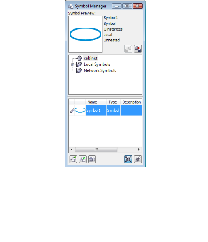
278 Corel DESIGNER X6 User Guide
If a symbol stored in a library is changed, you can update the link to refresh the symbol
instances.
You can revert a symbol instance to an object or objects while preserving its properties.
You can also delete a symbol instance, and purge unused symbol definitions. Purging
removes all symbol definitions that are not instanced in a drawing.
You use the Symbol manager docker to work with symbols.
Symbol manager docker
The preview area shows a symbol and information about it, including
•name
• number of instances in the active document
•type of link:
linked — the symbol definition is added from a library file
local — (also known as “internal”) the symbol was created in the active document
Working with symbols 279
or was made local by breaking a link
• type of symbol: nested or un-nested
Just below the preview area, a tree view lets you see all linked and local symbol
definitions in the active document, including symbols that are not instanced. You can
also navigate to symbol libraries.
Examples of symbols
To locate a symbol
1Click Edit Symbol Symbol manager.
2Click the active document at the top of the tree view to see symbols in the current
document.
Click a folder to choose a collection, and click a symbol library to see
symbols in a file.
To insert a symbol instance
1Click Edit Symbol Symbol manager.
2Choose a symbol library in the tree view.
3Choose a symbol from the Symbols list.
If you want the symbol scaled automatically to match the current drawing scale,
ensure that the Scale to world units button is enabled.
4Click the Insert symbol button .

280 Corel DESIGNER X6 User Guide
You can also insert a symbol instance by dragging a symbol from the Symbol
manager docker to the drawing window.
To modify a symbol instance
1Select a symbol instance in the drawing window.
2Make any changes.
If a symbol contains multiple objects, all objects in the symbol instance are
treated as if they were a group. You cannot modify individual objects in a
symbol instance.
Not all properties of a symbol instance can be modified. For a list of properties
that can be modified, see “Modifying symbol instances” on page 286.
To update a link
1Select a symbol in the active document.
2Click Edit Symbol Update from link.
You can also click Window Link manager and use the Links and
bookmarks docker to update links to symbols. An exclamation mark appears
next to objects that need to be updated.
To revert a symbol instance to an object or objects
1Select a symbol instance.
2Click Edit Symbol Revert to objects.
The symbol definition remains in the active document.
You can also revert a symbol instance to an object by right-clicking the symbol
instance and clicking Revert to objects.
Working with symbols 281
To delete a symbol instance
1Select a symbol instance.
2Press Delete.
The symbol definition remains in the active document.
To purge unused symbol definitions
1In the Symbol manager docker, click the active document.
2Click the Purge unused definitions button .
Managing collections and libraries
Most of the symbols you will use have already been created and are stored in library files
that are grouped into collections.
The Symbol manager docker always displays libraries and collections that are in your
local Symbols folder. You can add collections and libraries to your Symbols folder from
elsewhere on the network. When you insert a local or external symbol into a drawing,
a copy of the symbol definition is added to the document but it remains linked to the
source symbol.
To add a collection or library
1Click Window Symbol manager.
2In the tree, click Local symbols or Network symbols.
3Click the Add library button .
4Locate and choose a collection or library.
5Click OK.
By default, library files are referenced from their original location. If you want
to copy a library to your User symbols folder (under Application data for
your user name), enable the Copy libraries locally check box.
If you are adding a collection, you can enable the Recursive check box to
include subfolders.

282 Corel DESIGNER X6 User Guide
To delete a collection or library
1In the Symbol manager docker, click a collection or library.
2Press Delete.
The collection or library is removed from the tree in the Symbol manager
docker but files are not deleted.
Creating, editing, and deleting symbols
Local symbols can be created in three ways: by creating one on a blank drawing page,
by converting an existing object or objects to a symbol, or by making a linked symbol
a local one by breaking its link.
You can edit a local symbol; any changes you make affect all instances in a drawing.
Linked symbols cannot be edited within the drawing, but can be edited directly in the
library file where they are stored. You can tell whether a symbol is local or linked by
looking in the preview area of the Symbol manager docker.
If a nested symbol contains a local definition, you can edit the local symbol within the
drawing. External symbols in nested symbols can also be edited, but you must first
convert the external symbols to local. For information about converting symbols from
external to local, see “To make a linked symbol local” on page 283.
You can also delete a symbol from the drawing and remove all instances.
To convert an object to a symbol
1Select an object or multiple objects.
2Click Edit Symbol New symbol.
3Type a name for the symbol.
Symbols cannot span layers. If you convert objects on different layers to a
symbol, the objects are combined on the topmost object’s layer. For more
information about layers, see “Working with layers” on page 305.
Working with symbols 283
You can also convert an existing object or objects to a symbol by dragging the
object or objects to the Symbol manager docker. The symbol name is
automatically added.
To make a linked symbol local
1Select a symbol.
2Click Edit Symbol Break link.
If other instances of the symbol are in the drawing, the links to all instances are
broken.
You can also make a linked symbol local by right-clicking the symbol and
choosing Break link.
To edit a local symbol
1In the Symbol manager docker, click the active document, and choose a symbol
from the Symbols list.
If you want to name or rename the symbol, double-click the symbol’s name box,
and type a name.
2Click the Edit symbol button .
3Modify the objects on the drawing page.
4Click the Finish editing object tab in the lower-left corner of the drawing window.
Changes made to a symbol are automatically made to all instances in the active
drawing.
You cannot add layers while in symbol edit mode.
While editing a symbol, you can insert an instance of another symbol, which
creates a nested symbol. You cannot, however, insert an instance of the same
symbol.

284 Corel DESIGNER X6 User Guide
To edit a linked symbol
1Click File Open.
2Choose the drive and folder where the library is stored.
3Click a library filename.
Library files have a .csl filename extension.
4Click Open.
5In the Symbol manager docker, click the active document, and choose a symbol
from the Symbols list.
If you want to rename the symbol, click the name again, and type a new name.
6Click the Edit symbol button .
7Modify the objects on the drawing page.
8Click the Finish editing object tab in the lower-left corner of the drawing window.
9Click File Save.
You may need permission to change files on the network.
To edit a nested symbol
1In the Symbol manager docker, click the active document, and choose the nested
symbol from the Symbols list.
2Click the Edit symbol button .
3Modify the editable objects on the drawing page.
4Click the Finish editing object tab in the lower-left corner of the drawing window.
While you are editing a nested symbol, linked symbols cannot be edited.
To delete a symbol from a document
1In the Symbol manager docker, click the active document, and choose a symbol
from the Symbols list.
2Click the Delete symbol button .

Working with symbols 285
When you delete a symbol, it is removed from the active drawing, and all
instances of the symbol are removed from the drawing.
If the symbol is linked, its symbol definition is removed from the active
document but remains in the library file.
Sharing symbols between drawings
Symbols can be stored within a drawing or in library files. You can share symbols
between drawings by copying and pasting. Copying symbols to the Clipboard leaves the
originals in the drawing or library file.
You can also copy and paste instances of a symbol to and from the Clipboard. Pasting a
symbol instance places the symbol in the active document and also places an instance
of the symbol in the drawing. Subsequent pasting will place another instance of the
symbol in the drawing without adding to the document. Symbol instances are copied,
cut, and pasted in the same way other objects are. For more information, see “Copying,
duplicating, and deleting objects” on page 249.
You can export symbols from a document and create a new library file, or you can create
a symbol library from any drawing file. You can create a new library by exporting the
symbol library from a document or by saving the symbols in a drawing as a new library.
If you put the new file in a shared folder, other users will be able to use the symbols.
To copy, paste, or duplicate symbols
To Do the following
Copy symbols to the Clipboard In the Symbol manager docker, select the
symbol or symbols from the Symbols list,
right-click, and click Copy.
Paste symbols from the Clipboard In the Symbol manager docker, right-click,
and click Paste.
Duplicate symbols In the Symbol manager docker, right-click
the symbol, and click Duplicate.

286 Corel DESIGNER X6 User Guide
To export a symbol library
1In the Symbol manager docker, click the active document.
2Click the Export library button .
3Choose the drive and folder where you want to save the library file.
4Type a filename in the File name box.
5Click Save.
To create a new library
1Click File Save.
2Choose the drive and folder where you want to store the library.
3Type a filename in the File name box.
4Choose CSL - Corel Symbol Library from the Save as type list box.
5Click Save.
To add a symbol to an existing library
1Click File Open.
2Choose the drive and folder where the library is stored.
3Choose CSL - Corel Symbol Library from the Files of type list box.
4Click Open.
5In the Symbol manager docker, choose the library file where you want to add a
symbol.
6Paste a symbol to the document.
7Save the library file.
Reference: Working with symbols
This reference section contains additional information about working with symbols.

Working with symbols 287
Modifying symbol instances
The following object properties can be modified for symbol instances. If a symbol
contains multiple objects, all objects in the symbol instance are treated collectively as a
single object, just as if they were grouped.
Property Notes
Position Type values in the Object position boxes on
the Tr a n s f o r m toolbar. For more
information, see “Moving objects” on
page 255.
Size Type width and height values in the Object
size boxes on the Tr a n s f o r m toolbar. For
more information, see “Sizing and scaling
objects” on page 258.
Skew See “Skewing objects” on page 263.
Rotation angle Type a value in the Angle of rotation box on
the Tr a n s f o r m toolbar. For more
information, see “Rotating objects” on
page 261.
Transparency Uniform transparency only. In the Symbol
area of the Property manager docker, move
the Transparency slider. For more
information, see “Applying transparencies”
on page 439.
The transparency slider is disabled if the
symbol contains an object with transparency
already applied to it.
Mirroring See “Mirroring objects” on page 262.
Wrap paragraph text In the Summary area in the Property
manager docker, choose an option from the
Wrap paragraph text list box. See
“Wrapping text” on page 474.
Order See “Changing the order of objects” on
page 267.

288 Corel DESIGNER X6 User Guide
Unsupported object types
Most objects in Corel DESIGNER can be converted to symbols, with the following
exceptions.
Name The name of an instance is displayed in the
Object manager docker. Click twice to
change it.
Unsupported object type Notes
Linked or embedded objects
Callouts
Control objects in link groups All related objects in the link group must be
included in the symbol. For example, if an
object has a drop shadow, you cannot
convert the object without the drop shadow.
Linked bitmaps
Placed PDF or EPS files
Locked object Object must be unlocked.
Paragraph text
Connector and dimension lines Must be broken apart or included with the
linked object or objects
Guidelines
Rollovers You cannot convert a rollover to a symbol;
however, you can include a symbol instance
in a rollover state.
Property Notes

Creating objects for the Web 289
Creating objects for the Web
Corel DESIGNER lets you export objects that are optimized for viewing in a Web
browser. You can also create interactive rollovers from Corel DESIGNER objects. In
addition, you can add hyperlinks and bookmarks to a drawing.
After creating the Web-compatible object in Corel DESIGNER, you can add the object
to a design using a Web-authoring tool. You can also export the object to HTML. For
more information, see “Exporting to HTML” on page 779.
This section contains the following topics:
• Exporting bitmaps for the Web
• Saving and applying Web presets
• Exporting objects with transparent colors and backgrounds
• Creating rollovers
• Adding bookmarks and hyperlinks to documents
• Adding hotspots and alternate text to objects
Exporting bitmaps for the Web
Corel DESIGNER lets you export the following Web-compatible file formats: GIF,
PNG, and JPEG.
While specifying exporting options, you can preview an image with up to four different
configurations of settings. You can compare file formats, preset settings, download
speeds, compression, file size, image quality, and color range. You can also examine
previews by zooming and panning within the preview windows.

290 Corel DESIGNER X6 User Guide
Component Description
1. Preview window Displays a preview of the document.
2. Preview modes Lets you preview the adjustments in a single
or split frame.
3. Zooming and panning tools Lets you zoom in and out of a document
displayed in the preview window, pan an
image displayed at zoom level higher than
100%, and fit an image in the preview
window.
4. Eyedropper tool and sampled color swatch Lets you sample a color and display the
sampled color.
1
7
23
6
89
45

Creating objects for the Web 291
You can export Web-compatible files using preset settings. This allows you to optimize
the file, without the need to modify individual settings. You can also customize the
settings to produce a specific result. For example, you can adjust its color, display
quality, and file size.
Choosing a Web-compatible file format
This table is a quick reference for choosing a Web-compatible file format.
5. Preset list box Lets you choose preset settings for a file
format.
6. Export settings Lets you customize export setting, such as
color, display options, and size.
7. Format information Lets you view file-format information, which
is available for each preview frame.
8. Color information Displays the color values for a selected color.
9. Speed list box Lets you choose an Internet speed for saving
the file.
File format Ideal for
GIF Line drawings, text, images with few colors, or images with sharp
edges, such as scanned black-and-white images or logos.
GIF offers several advanced graphic options, including transparent
backgrounds, interlaced images, and animation. It also lets you
create custom palettes for the image.
PNG Various image types, including photos and line drawings.
The PNG file format (unlike the GIF and JPEG formats) supports
the alpha channel. This allows you to save transparent images with
superior results.
Component Description

292 Corel DESIGNER X6 User Guide
Exporting palette-based documents
Palette-based documents, such as paletted GIF and 8-bit PNG, allow individual pixels
to retain their exact color value. This lets you control the display of colors in the file
when exporting. Palette-based documents also allow you to introduce transparency to
a file by choosing a color in the image and making it transparent. For information, see
“Exporting objects with transparent colors and backgrounds” on page 297.
To adjust the object-export preview
1Click File Export for Web.
2Perform one or more tasks from the following table.
JPEG Photos and scanned images.
JPEG files use file compression to store an approximation of an
image, which results in some loss of image data, but does not
compromise the quality of most photographs. You can choose the
image quality when you save an image — the higher the image
quality, the larger the file size.
To Do the following
View the bitmap in a single preview frame Click the Full preview button on the
View toolbar.
View two versions of the bitmap in side-by-
side frames
Click the Two vertical previews button .
View the two versions of the bitmap with
one frame placed above the other
Click the Two horizontal previews
button .
View four versions of the bitmap in separate
frames
Click the Four previews button .
Fit a bitmap in the preview window Click the Zoom to fit button .
Display each pixel in the image data to a
single pixel on-screen
Click the Zoom 1:1 pixel button .
Display a bitmap at its actual size Click the Zoom to actual size button .
File format Ideal for
Creating objects for the Web 293
To export a Web-compatible bitmap
1Click File Export for Web.
2In the Export for Web dialog box, choose preset settings from the Preset list box
in the upper-right corner of the dialog box.
If you want modify the preset settings, you can change the exporting options in the
dialog box.
3Click Save as.
4Choose the drive and folder where you want to save the file.
5Ty p e a n a m e i n t h e File name box.
6Click Save.
You can also export to a Web-compatible format by clicking File Export,
and choosing a file format from the Save as type list box.
You can choose an Internet connection speed from the Speed list box at the
bottom of the dialog box.
Pan to another area of the bitmap Using the Pan tool , drag the image until
the area you want to see is visible.
Zoom in and out Using the Zoom in tool or Zoom out
tool , click in the preview window.
Change the display options for the object in
a preview frame
Click a frame, then choose different export
settings from the export settings area.
You can also
Choose a color mode In the Settings area, choose a color mode
from the Color mode list box.
This option is unavailable for the GIF file
format.
Embed the color profile In the Advanced area, enable the Embed
color profile check box.
To Do the following

294 Corel DESIGNER X6 User Guide
To resize an object when exporting a Web-compatible bitmap
•From the Export for Web dialog box, perform one or more tasks from the
following table.
To customize options for exporting a JPEG bitmap
1From the Export for Web dialog box, choose JPEG from the Format list box.
2Perform one or more tasks from the following table.
To Do the following
Choose a unit of measurement for the
bitmap
In the Transformation area, choose a unit of
measurement from the Units list box.
Specify the bitmap dimensions In the Tr a n s f o r m a t i o n area, type values in
the Width and Height boxes.
Resize the bitmap to a percentage of its
original size
In the Tr a n s f o r m a t i o n area, type values in
the Width % and Height % boxes.
Avoid distortion by maintaining the width-
to-height ratio of the bitmap
In the Tr a n s f o r m a t i o n area, enable the
Maintain aspect ratio check box.
Specify the bitmap resolution In the Tr a n s f o r m a t i o n area, type a value in
the Resolution box.
Maintain the size of the file on your hard
disk when you change the resolution of the
bitmap
In the Tr a n s f o r m a t i o n area, enable the
Maintain size check box.
To Do the following
Control document quality In the Settings area, choose a quality option
from the Quality list box, or type a
percentage value.
Choose an encoding setting In the Settings area, choose an option from
the Sub-format list box.
Blur the transition between adjacent pixels
of different colors
In the Settings area, type a value in the Blur
box.

Creating objects for the Web 295
To specify display-quality options for exporting Web-compatible bitmaps
•From the Export for Web dialog box, perform one or more tasks from the
following table.
Load the JPEG file gradually in certain Web
browsers to display only portions of the
image before it finishes loading
In the Advanced area, enable the
Progressive check box.
Use the optimal encoding method to
produce the smallest JPEG file size
In the Advanced area, enable the Optimize
check box.
You can also
Apply the document-color settings In the Advanced area, enable the Use
document color settings option.
Apply the color-proof settings to the
document
In the Advanced area, enable the Use color
proof settings option.
Enable the overprinting of black when
exporting to CMYK
In the Settings area, enable the Overprint
black check box.
Apply a matte color to the object’s
background to help blend the edges of anti-
aliased objects
In the Settings area, open the Matte color
picker, and click a color.
To Do the following
Apply a matte color to the object’s
background to help blend the edges of anti-
aliased objects
In the Settings area, open the Matte color
picker, and click a color.
Smooth the edges of the object In the Advanced area, enable the Anti-
aliased check box.
Load the file gradually in certain Web
browsers to display only portions of the
image before it finishes loading
In the Advanced area, enable the
Interlaced check box.
To Do the following

296 Corel DESIGNER X6 User Guide
To specify color settings for exporting palette-based Web-compatible bitmap
•From the Export for Web dialog box, perform one or more tasks from the
following table.
To Do the following
Choose a color mode In the Settings area, choose a color mode
from the Color mode list box.
This option is unavailable for the GIF file
format.
Choose a color palette In the Settings area, choose a palette from
the Color palette list box.
Specify a dithering setting and amount In the Settings area, choose a dithering
option from the Dithering list box, and type
a value in the box.
Embed the color profile In the Advanced area, enable the Embed
color profile check box.
You can also
Load a color palette In the Settings area, click the arrow next to
Color palette list box, and click Load
palette.
Sample a color and add it to a color palette Click the Eyedropper on the toolbar, and
then click in the drawing window to choose
a color. In the Settings area, click the Add
the sampled color to palette button .
Add or modify colors Double-click a color swatch on the color
palette.
Choose the number of colors that you want
to display
In the Settings area, choose a value from the
Number of colors list box.
Delete a color from the color palette In the Settings area, click a color on the
color palette, and then click the Delete the
selected color button.

Creating objects for the Web 297
You can also add transparency to a palette-based document by choosing a color
in the image and making it transparent. For information, see “Exporting
objects with transparent colors and backgrounds” on page 297.
Saving and applying Web presets
Web presets allow you to save custom settings for exporting Web-compatible file
formats.
To save a preset for exporting Web-compatible images
1From the Export for Web dialog box, choose a file format from the Format list
box.
2Choose the settings that you want to store as a preset.
3Click the arrow next to the Preset list box, and click Save preset.
4Type the name of the preset in the File name box.
5Click Save.
You can delete a saved preset by choosing a preset from the Preset list box,
clicking the arrow next to the Preset list box, and clicking Delete preset.
To apply a preset for exporting Web-compatible images
1From the Export for Web dialog box, click the arrow next to the Preset list box,
and click Load preset.
2Click the name of the file.
3Click Open.
Exporting objects with transparent colors and backgrounds
Corel DESIGNER lets you export palette-based bitmaps, such as paletted GIF or 8-bit
PNG, with transparent colors and backgrounds. These bitmaps can contain objects,
such as buttons and logos, which are commonly used on Web pages with colored or
patterned backgrounds.
298 Corel DESIGNER X6 User Guide
If you place an object with an opaque background onto a Web page, the object
background color appears as a rectangle on the page. By making an object background
transparent, the object background blends in with the page. Transparent object
backgrounds also let you change the color or pattern of a Web page background
without having to change the backgrounds of the objects to match.
You can create a GIF with a transparent background to use on a Web page.
To save a bitmap with a transparent background
1From the Export for Web dialog box, choose a paletted file format, such as GIF or
8-bit PNG, from the Format list box.
2Perform one or more tasks from the following table.
For best results, choose None from the Dithering list box in the Settings area.
To Do the following
Make the background of the object
transparent
In the Settings area, enable the
Tr a n s p a r e n c y check box.
Make a selected color transparent Click the Eyedropper on the toolbar, and
then click the image to choose a color. In the
Settings area, click the Make the selected
color transparent button .
Apply a matte color to the object’s
background to help blend the edges of anti-
aliased objects
In the Settings area, open the Matte color
picker, and click a color.
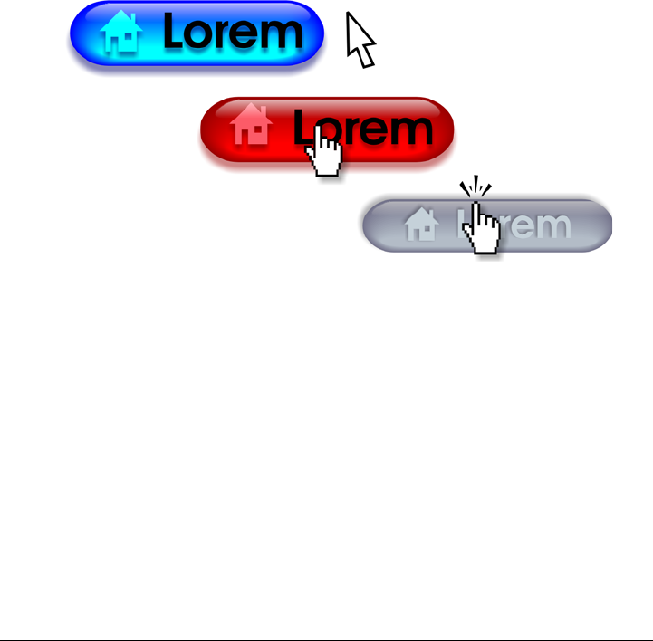
Creating objects for the Web 299
Creating rollovers
Rollovers are interactive objects that change in appearance when you click or point to
them. You can create rollovers using objects.
To create a rollover, you add the following rollover states:
•Normal — the default state of a button when no mouse activity is associated with
the button
•Over — the state of a button when the pointer passes over it
•Down — the state of a clicked button
You can apply different object properties to each of the rollover states. You can also
preview the rollover states.
Rollovers showing Normal (left), Over (center), and Down (right) states
To add the rollover object to a web design, you must first save it to Macromedia®
Flash® (SWF) format. For more information about creating and editing objects such as
rollovers, see “Working with objects” on page 245.
To create a rollover object
1Select an object.
2Click Effects Rollover Create rollover.
To modify an object’s rollover state
1Click View To o l b a r s Internet.
The Internet toolbar appears.
300 Corel DESIGNER X6 User Guide
2Click the rollover object to select it.
3On the Internet toolbar, click the Edit rollover button .
4From the Active rollover state list box, choose a state:
• Normal
• Over
• Down
5Modify the object properties, such as the color.
6Click the Finish editing rollover button .
You cannot close a drawing in which you are editing a rollover. You must finish
editing first.
To view rollover properties
1Click Window Object manager.
2Click the page and layer where the rollover resides.
3Click the rollover name, and expand the Normal, Over, and Down states.
You can preview a rollover object’s states in the drawing page by clicking the
Live preview of rollovers button on the Internet toolbar. To quit
previewing the rollover so that you can edit it, click the Live preview of
rollovers button . You cannot undo while previewing a rollover.
You can also
Delete a rollover state On the Internet toolbar, click the Deletes
rollover state button .
Duplicate a rollover state On the Internet toolbar, click the
Duplicate states button .
Undo a rollover On the Internet toolbar, click the Extract
all objects from rollover button .
Specify what frame appears when the
rollover is clicked
On the Internet toolbar, choose a target
frame from the Ta r g e t f r a m e list box.
Creating objects for the Web 301
Adding bookmarks and hyperlinks to documents
Corel DESIGNER lets you add bookmarks and hyperlinks to your document. You can
apply these to objects, including text objects, rollovers, and bitmaps. For information,
see “Including hyperlinks, bookmarks, and thumbnails in PDF files” on page 761.
Bookmarks
To create an internal link within a file, you can assign a bookmark to text or to an object.
You can then assign a link to an object so that, when it’s clicked, it opens the bookmark.
Hyperlinks
You can also assign a hyperlink to an object. You can link to a Web address, FTP server,
email address, bookmark, or file. When the object is clicked, it opens to the assigned
location in a appropriate application. After you create hyperlinks, you can display and
verify them. You can also delete links and bookmarks. When working with text, you
can assign a hyperlink to both artistic and paragraph text.
Hyperlinks are maintained when you export files to CGM Version 4 profiles. For
information about exporting CGM files, see “Computer Graphics Metafile (CGM)” on
page 792.
To assign a bookmark
1Click Window Links and bookmarks.
2In the workspace, click the object that you want to bookmark.
3Click the New bookmark button .
4Type the name of the bookmark in the name box.
To assign a hyperlink to an object
1Click Window Links and bookmarks.
2In the workspace, click the object to which you want to apply a hyperlink.
3Click the New link button .
4From the Link type list box, choose one of the following link types:
Link types
http:// Type a Web address, or URL, for a Web page
that opens when you click the link.
302 Corel DESIGNER X6 User Guide
To assign a hyperlink to text
1Click Window Links and bookmarks.
2Using the Te x t tool , select the text characters to which you want to assign a
hyperlink.
3Click the New link button .
4From the Link type list box, choose one of the following link types:
You can also assign a hyperlink from the Internet toolbar by clicking View
To o l b a r s Internet to display the toolbar.
To verify a link
1Click Window Links and bookmarks.
2Choose the link that you want to open.
3Click the Open link button .
To delete a bookmark or link
1Click Window Links and bookmarks.
2Choose the link or bookmark that you want to delete.
3Click the Delete button .
ftp:// Type a Web address, or URL, to the FTP
server that opens when you click the link.
mailto: Type an email address.
file:// Click the browse button and navigate to the
file that you want to open when you click
the link.
bookmark Choose a previously created bookmark from
the list.
Link types
Creating objects for the Web 303
Adding hotspots and alternate text to objects
You can also set a hotspot that follows the outline of the object, or fills the object’s
bounding box. Corel DESIGNER applies a crosshatch pattern to an object containing
a link. You can change the color of the crosshatch pattern as well as its background fill.
In addition, you can add alternate text to objects for text-only browsers or screen
readers.
To set a hotspot
1Click Window Property manager.
2Click the Internet button .
3Choose Link from the Behavior list box, and type a Web address in the URL box.
4In the Define hotspot using area, click one of the following buttons:
• Shape — defines the hotspot using the object’s shape
• Bounds — defines the hotspot using the object’s bounding box
5Open the Cross-hatch color picker , and click a color.
6Open the Background color picker , and click a color.
If you choose a hyperlinked object first and then change the crosshatch and
background hotspot colors, the change applies to the selected object only.
To add alternate text to an object
1Click Window Property manager.
2Click the Internet button .
3Type the alternate text in the ALT comments text box.
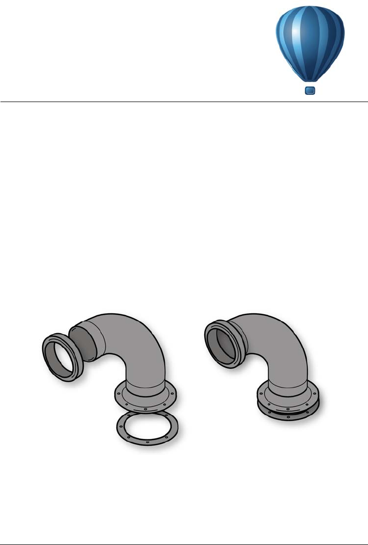
Working with layers 305
Working with layers
You can work with layers to help you organize and arrange objects in complex
illustrations.
This section contains the following topics:
• Creating layers
• Changing layer properties
• Moving and copying layers and objects
Creating layers
All Corel DESIGNER drawings consist of stacked objects. The vertical order of these
objects — the stacking order — contributes to the appearance of the drawing. An
effective way to organize these objects is by using invisible planes called layers.
Drawings can be assembled by placing objects on various levels or layers.
Layering gives you added flexibility when you organize and edit the objects in complex
drawings. You can divide a drawing into multiple layers, each containing a portion of
the drawing’s contents. For example, you can use layers to organize an architectural

306 Corel DESIGNER X6 User Guide
plan for a building. You can organize the building’s various components (for example,
plumbing, electrical, structural) by placing them on separate layers.
Local layers and master layers
All content is placed on a layer. Content that applies to a specific page is placed on a
local layer. Content that applies to all pages in a document can be placed on a global
layer called a master layer. Master layers are stored on a virtual page called the Master
Page.
The Object manager docker displays the default layer structure. The names
of the active page and layer appear at the top.
You can create master layers for all pages, for even pages, or for odd pages. For example,
placing content on an even master layer means that the content will appear on all even
pages but not on the odd pages.
Each new file is created with a default page (Page 1) and a Master Page. The default
page contains the following layers:
•Guides — stores page-specific (local) guidelines. All objects placed on the Guides
layer appear as outlines only, and the outlines act as guidelines.
•Layer 1 — represents the default local layer. When you draw objects on the page,
the objects are added to this layer unless you choose a different layer.
The Master Page is a virtual page that contains the information that applies to all pages
in a document. You can add one or more layers to a master page to hold content such
as headers, footers, or a static background. By default, a master page contains the
following layers:
Working with layers 307
•Guides (all pages) — contains the guidelines that are used for all pages of the
document. All objects placed on the Guides layer appear as outlines only, and the
outlines act as guidelines.
•Desktop — contains objects that are outside the borders of the drawing page. This
layer lets you store objects that you may want to include in the drawing at a later
time.
•Document grid — contains the document grid that is used for all pages of the
document. The document grid is always the bottom layer.
The default layers on the master page cannot be deleted or copied. Layers that you add
to the master page appear at the top of the stacking order unless the stacking order is
changed in the Current page, layers only view in the Object manager docker
(accessible through the Layer manager view button).
To add content to a layer, you must first select the layer so that it becomes the active
layer.
Viewing layers, pages, and objects
You can choose different views that let you display pages, layers, or all the objects in
your document. The view you choose depends on the complexity of your document and
the task you are performing. For example, in a long multipage document, you can
choose a pages-only view so that you can navigate the document more easily and view
only one page at a time. The Current page, layers only view lets you view and reorder
all the layers that affect the current page, including the master layers.
To create a layer
1If the Object manager docker is not open, click Window Object manager.
2Perform a task from the following table.
To Do the following
Create a local layer In the upper-right corner of the Object
manager docker, click the flyout button ,
and click New layer.
Create a master layer for all pages In the upper-right corner of the Object
manager docker, click the flyout button ,
and click New master layer (all pages).
308 Corel DESIGNER X6 User Guide
To use a layer in the drawing, you must first make the layer active by clicking
the layer name in the Object manager docker. The layer name appears in a
red bold font to indicate that it is the active layer. When you start a drawing,
the default layer (Layer 1) is the active layer.
Master layers are always added to the master page. Content added to these
layers is visible on all pages of the document, all odd pages, or all even pages,
depending on the type of master layer that you have chosen.
Master layers for odd and even pages cannot be created in Facing Pages view.
If you have created odd and even master pages before switching to Facing
Pages view, the odd and even master layers will be converted to all-page master
layers. For more information about facing pages, see “To view facing pages” on
page 73.
You can also add a layer by clicking the New layer button in the Object
manager docker.
You can also create new master layers by clicking the respective button in the
Object manager docker: New master layer (all pages) , New master
layer (odd pages) , or New master layer (even pages) .
You can make any layer a master layer by right-clicking the layer name, and
clicking Master (all pages), Master (odd pages), or Master (even pages).
Create a master layer for odd pages In the upper-right corner of the Object
manager docker, click the flyout button ,
and click New master layer (odd pages).
This command is available only when the
active page is an odd page.
Create a master layer for even pages In the upper-right corner of the Object
manager docker, click the flyout button ,
and click New master layer (even pages).
This command is available only when the
active page is an even page.
To Do the following
Working with layers 309
To make a layer active
1If the Object manager docker is not open, click Window Object manager.
2In the Object manager docker, click the layer name.
The layer name appears in a red bold font to indicate that it is the active layer.
By default, the active layer is Layer 1.
The name of the active layer, as well as the currently selected object, appears
in the status bar at the bottom of the application window. The names of the
active page and layer also appear at the top of the Object manager docker.
To display pages, layers, and objects in the Object Manager docker
1If the Object manager docker is not open, click Window Object manager.
2Perform a task from the following table.
The name of the active layer, as well as the currently selected object, appears
in the status bar at the bottom of the application window. The names of the
active page and layer also appear at the top of the Object manager docker.
To delete a layer
1If the Object manager docker is not open, click Window Object manager.
To Do the following
Display pages Click the flyout button , and then click
Show pages.
Display all layers for the current page Click the name of a page, click the Layer
manager view button , and then click
Current page, layers only.
Display all layers and objects across all pages Click the Layer manager view button ,
and then click All pages, layers and
objects.
Display objects Click the flyout button , and then click
Expand to show selection.
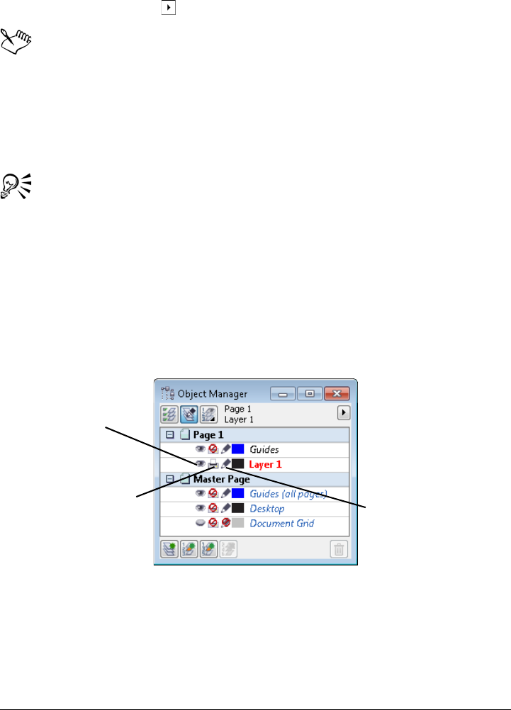
310 Corel DESIGNER X6 User Guide
2Click the name of a layer.
3Click the flyout button , and click Delete layer.
When you delete a layer, you also delete all the objects on it. To preserve an
object, move it to a different layer before you delete the current layer.
You can delete any unlocked layer except the following default layers:
Document grid, Desktop, Guides, and Guides (all pages). For more
information about locking and unlocking layers, see “To set the editing
properties of a layer” on page 312.
You can also delete a layer by right-clicking the layer name in the Object
manager docker and choosing Delete.
Changing layer properties
For each new layer that you create, the display, editing, and printing and exporting
properties are enabled by default. You can change these properties at any time. You can
also turn a local layer into a master layer, or a master layer into a local layer. For
information about master layers, see “Creating layers” on page 305.
The icons to the left of a layer’s name let you change the layer’s properties.
Showing and hiding layers
You can choose to show or hide layers in a drawing. Hiding a layer lets you identify and
edit the objects on other layers. It also reduces the time required for your drawing to
refresh when you edit it.
Displays or hides the
layer
Enables or disables
printing and
exporting for a layer
Makes a layer editable
or locks it to prevent
changes

Working with layers 311
Printing and exporting layers
You can set printing and exporting properties for a layer to control whether a layer is
displayed in the printed or exported drawing. Note that hidden layers are displayed in
the final output if the printing and exporting properties are enabled. The Document
grid layer cannot be printed or exported.
Setting a layer’s editing properties
You can allow editing of the objects on all layers or restrict editing so that you can only
edit objects on the active layer. You can also lock a layer to prevent accidental changes
to the objects it contains. When you lock a layer, you cannot select or edit the objects
on that layer.
Renaming layers
You can rename layers to indicate their contents, their position in the stacking order, or
their relationship with other layers.
Using layer color to view objects
You can change the layer color so that objects on the layer are displayed with the layer
color when you use Wireframe view. For example, if you place various components of an
architectural plan (plumbing, electrical, structural) on separate layers, you can use layer
color to quickly identify to which component the objects belong.
To change layer properties
1If the Object manager docker is not open, click Window Object manager.
2Right-click the layer, and click Properties.
3Specify the settings you want.
To show or hide a layer
1If the Object manager docker is not open, click Window Object manager.
2Click the Show or hide icon beside the layer name.
The layer is hidden when the Show or hide icon is grayed out.
Objects on a hidden layer are displayed in the printed or exported drawing
unless the layer’s printing and exporting properties are disabled.
312 Corel DESIGNER X6 User Guide
You can also show or hide a layer by right-clicking the layer in the Object
manager docker and then clicking Visible.
To enable or disable printing and exporting of a layer
1If the Object manager docker is not open, click Window Object manager.
2Click the Enable or disable printing and exporting icon beside the layer
name.
Disabling the printing and exporting of a layer prevents its contents from
appearing in the printed or exported drawing, or in full-screen previews. For
information about full-screen previews, see “Previewing drawings” on page 68.
You can also enable or disable the printing and exporting of a layer by right-
clicking the layer in the Object manager docker and clicking Printable.
To set the editing properties of a layer
1If the Object manager docker is not open, click Window Object manager.
2In the Object manager docker, click the name of the layer that you want to edit.
The layer name appears in a red bold font to indicate that the layer is active.
3Perform a task from the following table.
If you disable editing across layers, you can work only on the active layer and
the Desktop layer. You cannot select or edit objects on inactive layers. For
To Do the following
Lock or unlock a layer Click the Lock or unlock icon beside the
layer name.
Allow editing on all layers Click the flyout button , and click Edit
across layers.
Allow editing on the active layer only Click the flyout button , and disable Edit
across layers.

Working with layers 313
example, if you use the Pick tool to marquee-select multiple objects on the
drawing page, only the objects on the active layer are selected.
You cannot lock or unlock the Document grid layer.
You can also allow editing on all layers by clicking the Edit across layers
button in the Object manager docker. Editing across layers is enabled
when the button appears pressed. Clicking the button again restricts editing to
the active layer.
You can also lock or unlock a layer by right-clicking the layer in the Object
manager docker and then clicking Editable.
To rename a layer
1If the Object manager docker is not open, click Window Object manager.
2Right-click the layer name, and click Rename.
You can also rename a layer by clicking the layer name twice and typing a new
name.
To change the layer color
•In the Object manager docker, double-click the color swatch that appears to the
left of the layer name, and choose a color.
Objects on the layer are displayed with the layer color when you use Wireframe
view (View Wireframe).
You can also choose to display only the objects on a specific layer in Wireframe
view by right-clicking the layer name, choosing Properties, and enabling the
Override full color view check box in the layer properties dialog box.
Moving and copying layers and objects
You can move or copy layers on a single page or between pages. You can also move or
copy selected objects to new layers, including layers on the master page.
Moving and copying layers affects the stacking order. Moving or copying an object to a
layer below its current layer causes the object to become the top object on its new layer.

314 Corel DESIGNER X6 User Guide
Similarly, moving or copying an object to a layer above its current layer causes the object
to become the bottom object on its new layer.
To move a layer
1If the Object manager docker is not open, click Window Object manager.
2In the layers list, drag a layer name to a new position.
You can change the order of the master layers relative to local layers by
displaying the list of all layers for the current page and dragging a layer name
to a new position in the layers list. To display all layers for a page, click a page
name, click the Layer manager view button at the top of the Object
manager docker, and choose Current page, layers only.
To copy a layer
1If the Object manager docker is not open, click Window Object manager.
2In the layers list, right-click the layer that you want to copy, and click Copy.
3Right-click the layer above which you want to place the copied layer, and click
Paste.
The layer and the objects it contains are pasted above the selected layer.
To move or copy an object to another layer
1If the Object manager docker is not open, click Window Object manager.
2Click an object in the Object manager docker.
3Click the flyout button , and click one of the following:
• Move to layer
• Copy to layer
4Click the destination layer.
When you move objects to or from a layer, the layer must be unlocked.
You can move and copy an object to another layer by dragging the object to a
new layer in the Object manager docker.

Object linking and embedding 315
Object linking and embedding
Object linking and embedding (OLE) is a method of exchanging information between
applications. Using OLE, you can take selected objects or entire files from one
application, called the source application, and place them into another application,
called the destination application. Objects that are placed into an application using
OLE are called OLE objects. You can freely move objects and files between applications
as long as all the applications involved support OLE.
Corel DESIGNER lets you create and edit OLE objects, as well as insert objects and files
created in other applications.
Linking results in a larger file size but is useful when you want to use an object or file
in multiple files. To change every instance of the object or the file, you only need to
change the object in the source application. Linking is also useful when the destination
application does not directly support files created in the source application. Embedding
is useful when you want to include all objects in one file.
This section contains the following topics:
• Inserting linked or embedded objects
• Editing linked or embedded objects
Inserting linked or embedded objects
You can insert a linked or embedded object. A linked object remains connected to its
source file; whereas an embedded object is not linked to its source file but is integrated
into the new file. You can insert an embedded object or create an embedded object. You
can also insert a linked or embedded object by copying it from the source application
and pasting it to the destination application.
To insert a linked object
1In the source application, select an object.
2Click Edit Copy.

316 Corel DESIGNER X6 User Guide
3In Corel DESIGNER, click Edit Paste special.
4Enable the Paste link option.
The file from which you copy the object in the source application must be saved
before you insert the object in Corel DESIGNER.
To insert an embedded object
1Click Edit Insert new object.
2Enable the Create from file option.
3Click the Browse button.
4Click a filename.
You can also create an embedded object by enabling the Create new option in
the Insert new object dialog box, and choosing the application in which you
want to create the object from the Object type list box.
You can also insert an embedded object by selecting an object in the source
application, and dragging it to the application window of Corel DESIGNER.
Editing linked or embedded objects
You can edit a linked or embedded object. You can edit a linked object by editing its
source file. Any changes you make to the source file are automatically applied to the
linked object. You can also modify a linked object; for example, you can update a linked
object, substitute the source file of a linked object for another, or break a link between
a linked object and its source file.
To edit a linked or embedded object
1Double-click the linked or embedded object to start the source application.
2Edit the object in the source application.
3Save the changes in the source application.
4Close the source application.
5Return to the active application window to review the edits.

Object linking and embedding 317
In most cases, you can edit OLE objects only in the source application. If you
try to change an OLE object using Corel DESIGNER, note the following
limitations. Depending on the source of the OLE object, you might not be able
to rotate, skew, clone, trim, weld, intersect, use as symbols, or combine OLE
objects. Also, you might not be able to apply any of the effects in the Effects
menu to OLE objects, except for PowerClip objects. You can only size, move,
and copy OLE objects and place them into PowerClip containers.
You can also edit linked or embedded objects by starting the source application
and opening the file directly.
To modify a linked object
1Select a linked object using the Pick tool .
2Click Edit Links.
3Click one of the following buttons:
• Update now — updates the linked object to reflect changes made in the source
file
• Open source — opens the object in the source application
• Change source — redirects the link to another file
• Break link — disconnects the link so that the object is embedded in the file

Working with object data 319
Working with object data
The Object Data Manager is an advanced hotspotting feature that is particularly
useful as a project management tool when you create or supervise a large project. You
can enter many types of project data about individual objects or groups of objects.
This section contains the following topics:
• Setting up the project database
• Managing object data
• Applying CGM data to objects
Setting up the project database
Before you assign project data to objects in a drawing, you need to know what
information you want to display. By default, Corel DESIGNER creates multiple data
fields including: Name, Cost, and Comments. These fields can be edited or deleted as
required.
Corel DESIGNER also provides common ActiveCGM®, WebCGM, and WebCGM
S1000D fields. When you import or export CGM files, the object data is maintained.
For more information on importing and exporting CGM files, see “Computer Graphics
Metafile (CGM)” on page 792.
Object data is also maintained when you import or export SVG files. For more
information on importing and exporting SVG files, see “Scalable Vector Graphics
(SVG)” on page 833.
You can create and assign as many data fields as you want, as long as they use permitted
format variables. For more information about assigning data fields, see “Managing
object data” on page 321. In addition, you can add a child field to an existing field to
create a hierarchical structure. However, the field you choose must support the creation
of a child field.
At any time, you can change the setting, such as the name or format, of a data field.

320 Corel DESIGNER X6 User Guide
If you require custom fields, you can define their formats using four basic field formats:
General, Date/time, Linear/angular, and Numeric. Each of these formats provides a
series of common settings. If the preset formats in Corel DESIGNER don’t provide the
information you want in your data summary, you can create your own custom formats
using the variables available for the format type you’re using. The field format you select
is used for all objects in the active drawing.
When you delete a field, you also delete all data entered for that field in the active
document and any children that are associated with the field.
To add a data field
1Click Window Object data manager.
2In the Object data docker, click the Open field editor button .
3In the Object data field editor dialog box, click New field.
4Double-click the Element name cell in the new field. Choose an element type
from the list box, and press Enter.
5Double-click the Name cell in the new field. Type a name for the field, and press
Enter.
If you want to change the field’s value, double-click the Default value cell, type a
new value, and press Enter.
If you want to change the field’s constraint, double-click the Constraint cell, type
a constraint, and press Enter.
6Double-click the Ty p e cell in the new field, and choose one of the following format
types from the list box:
• String
• Number
• Event
• Action
7Double-click the Ta r g e t cell in the new field, and choose one of the following
targets from the list box:
• General
• ActiveCGM
• Web CGM
8In the Add field to area, enable one or both of the following check boxes:
• Application defaults — stores the new field in the application
• Document defaults — stores the new field in the current document

Working with object data 321
You can also use this procedure to change the settings of an existing data field.
Managing object data
After creating all the data fields you want for a drawing, you can create a database from
a template. The database stores all the data you apply to the objects in your drawing.
You can choose from three different templates; because each template saves to an
external, tagged XML file, you can store the data for different workflows
simultaneously.
The Object Data Manager provides all the commands and features you need to add,
edit, and delete object data — even behaviors that were applied using the Internet
toolbar.
You can also
Add a child data field to an existing field Select the data field to which you want to
add a child, and click New child field.
The field you choose as a parent field must
support the creation of a child field.
Change the format of a data field Select the data field, and click Change in the
Format area.
In the Format definition dialog box, enable
the option beside the format type you want
to use, and choose a format from the Format
type list.
Create a custom format for a data field Select the data field, and click Change in the
Format area.
In the Format definition dialog box, enable
the option beside the format type you want
to create.
Type the format in the Create box, and press
Enter.
Delete a data field Choose the name of the data field from the
list. To choose multiple fields, hold down
Ctrl, and click the names in the list.
Click Delete field(s).
322 Corel DESIGNER X6 User Guide
You can use one object’s data entries to update another object’s data entries. This
function does not replace an object’s data entries; rather, it appends fields and data
where appropriate.
Corel DESIGNER also provides common ActiveCGM, WebCGM, and WebCGM
S1000D fields. When you import or export CGM files, the object data is maintained.
For more information on importing and exporting CGM files, see “Computer Graphics
Metafile (CGM)” on page 792.
Object data is also maintained when you import or export SVG files. For more
information about importing and exporting SVG files, see “Scalable Vector Graphics
(SVG)” on page 833.
To choose a database template
1Click Window Object data manager.
2From the list box, choose one of the following templates:
• General
• ActiveCGM
• S1000D issue 4.0
• Web C GM
You can also view all existing database entries by choosing All from the list
box.
To add or edit data for an object
1Select the object using the Pick tool .
2Click Window Object data manager.
3Select a data field.
A check mark indicates whether that field is applied to the selected object.
An icon indicates the field type:
• Te x t
• Number
• Action
• Event
4Type text in the Value column for the field, and press Enter.
Working with object data 323
5Double-click in the Constraint column for the field, and specify a constraint value
in the Object data field editor dialog box.
6Repeat steps 3 to 5 to add data to other fields.
Applying CGM data to objects
This section provides a sample of the CGM data that you can apply to objects. It is
divided into three parts:
• Sample of WebCGM commands
• Sample of ActiveCGM commands
• Sample of WebCGM S1000D commands
When you choose an action as the type, any of the following can function as
the value:
• one or more ActiveCGM commands
• BasicScript® subroutine name
• operating system command
• external application
When you choose an event as the type, only one or more Active CGM
commands can function as the value.
You can also
Display or hide behaviors Click the Show/hide behaviors button .
Display or hide data Click the Show/hide data button .
Display active fields only Click the Show active fields only button
.
Copy data from another object to the
selected object
Click the Copy data from button , and
click the object from which you want to copy
data.
Clear all fields Click the Clear all fields button .

324 Corel DESIGNER X6 User Guide
Sample of WebCGM commands
button1press
•Ty p e : event
•Description: Triggers when you click any of the members of the group.
•Value: WebCGM_button1press, or any of the WebCGM actions
•Constraint: none
content
•Ty p e : text
•Description: Allows you to declare the first priority when searching the text
content of a ‘para’ APS.
•Value: none
•Constraint: none
cursorenter
•Ty p e : event
•Description: Triggers when the pointer moves within two pixels of any of the
members of the group.
•Value: WebCGM_cursorenter, or any of the WebCGM actions
•Constraint: none
cursorexit
•Ty p e : event
•Description: Triggers when the pointer moves off all members of the group.
•Value: WebCGM_cursorexit, or any of the WebCGM actions.
•Constraint: none
hover
•Ty p e : event
•Description: Triggers when the pointer moves over any member of the group.
•Value: any of the WebCGM actions
•Constraint: none
linkuri
•Ty p e : action
•Description: Loads a file in the target window as specified by the URI.
•Value: either one or three strings entered by user input

Working with object data 325
• If it is one string, it will represent the URI.
Example: “http://www.corel.com”
• If it is three strings, the first string is the URI, the second is the empty string,
and the third is the target frame.
Example: “http://www.corel.com” “” “_blank”
The target frames are as follows:
•_blank — viewer loads the content in a new window
•_self — viewer loads the content in the same window
•_parent — viewer loads the content in the immediate frameset parent
of the active window
•_top — viewer loads the content in the full original window
•Constraint: none
name
•Ty p e : text
•Description: Names the group.
•Value: entered by user input
Example: “Corel Designer Group”
•Constraint: none
region
•Ty p e : text
•Description: Provides an optional spatial region, associated with a graphic object,
allowing the user to pick operations for the object. Simple regions of type rectangle,
ellipse, polygon, and continuous polybezier can be defined.
• For a rectangle, two corner points of the viewport are provided, as in (x1,y1)
(x2,y2).
Example: -820084 215104 342822 867138
• For an ellipse, three points are provided. The first point specifies the center of the
ellipse, while the remaining two points specify the CDP points, as in (x1,y1)
(x2,y2) (x3,y3).
Example: -275602 514233 -786474 514233 -275602 282324
• For a polygon, points are provided where n is the number of vertices in the
polygon using the formula n*(x.y).
• For a polybezier, points are provided where n is the number of contiguous cubic
segments using the formula 3n+1(x,y).
Example (polybezier with three vertices): 235270 712532 -235270
712532 342822 87386 342822 87386 342822 87386 -235270

326 Corel DESIGNER X6 User Guide
87386 -235270 87386 -235270 87386 -235270 712532 -
235270 712532
•Value: none
•Constraint: none
screentip
•Ty p e : text
•Description: Causes the value to be displayed as a screen-tip when the pointer is
positioned over the group.
•Value: entered by user input as a single string that is associated with a graphic
object or a group
Example: “This is a screentip”
•Constraint: none
viewcontext
•Ty p e : number
•Description: Lets you specify the initial view of an object when you position the
pointer over the graphic object that contains this attribute.
The value of the viewcontext specifies the two corner points of the viewport
rectangle as (x1,y1) (x2,y2), where x1, y1 is the top-right point of the viewport
rectangle and x2, y2 is the bottom-left point of the viewport rectangle.
Example: -925688030 586990613 -799207691 509452731
•Value: entered by user input
•Constraint: none
WebCGM_button1press
•Ty p e : action
•Description: Erases all usertip message boxes in the target window.
Example: ‘eraseusertip;execute -extension “linkuri”’
•Value: eraseusertip;execute -ext
•Constraint: none
WebCGM_cursorenter
•Ty p e : action
•Description: Displays the specified usertip.
Example: ‘displayusertip -tip “<This is a screentip>”’
•Value: displayusertip -tip
•Constraint: none

Working with object data 327
WebCGM_cursorexit
•Ty p e : action
•Description: Erases all usertip message boxes in the target window.
•Value: eraseusertip
•Constraint: none
Sample of ActiveCGM commands
@ML_button1press
•Ty p e : event
•Description: Makes the group visible.
•Value: @ML_ToVisible
•Constraint: none
@ML_button1release
•Ty p e : event
•Description: Makes the group invisible.
•Value: @ML_ToInvisible
•Constraint: none
@ML_cursorenter
•Ty p e : event
•Description: Changes the group color to red.
•Value: @ML_ToRed
•Constraint: none
@ML_cursorexit
•Ty p e : event
•Description: Changes the group color to its original color.
•Value: @ML_ToNative
•Constraint: none
@ML_ToInvisible
•Ty p e : action
•Description: Makes the group invisible.
•Value: changegroup -vis off
•Constraint: fixed
@ML_ToNative

328 Corel DESIGNER X6 User Guide
•Ty p e : action
•Description: Changes the group color to its original color.
•Value: changegroup -co native
•Constraint: fixed
@ML_ToRed
•Ty p e : action
•Description: Changes the group color to red.
•Value: changegroup -co red
•Constraint: fixed
@ML_ToVisible
•Ty p e : action
•Description: Makes the group visible.
•Value: changegroup -vis on
•Constraint: fixed
button1press
•Ty p e : event
•Description: Triggers when you click any of the members of the group.
•Value: PressButton1, or any of the WebCGM or ActiveCGM actions
•Constraint: none
button1release
•Ty p e : event
•Description: Triggers when you release the left mouse button while the pointer is
positioned over any of the members of the group.
•Value: ReleaseButton1, or any of the WebCGM or ActiveCGM actions
•Constraint: none
cursorenter
•Ty p e : event
•Description: Triggers when the pointer moves within two pixels of any of the
members of the group.
•Value: ToRed, or any of the WebCGM or ActiveCGM actions
•Constraint: none
cursorexit
•Ty p e : event

Working with object data 329
•Description: Triggers when the pointer moves off all members of the group.
•Value: ToNative, or any of the WebCGM or ActiveCGM actions
•Constraint: none
description
•Ty p e : text
•Description: This behavior is undefined.
•Value: entered by user input
Example: “product description”
•Constraint: fixed
Sample of WebCGM S1000D commands
desc
•Ty p e : text
•Description: This behavior is undefined.
•Value: entered by user input
Example: “product description”
•Constraint: fixed
linkuri
•Ty p e : action
•Description: Loads a file in the target window as specified by the URI.
•Value: either one or three strings entered by user input
• If it is one string, it will represent the URI.
Example: “http://www.corel.com”
• If it is three strings, the first string is the URI, the second is the empty string,
and the third is the target frame.
Example: “http://www.corel.com” “” “_blank”
The target frames are as follows:
•_blank — viewer loads the content in a new window
•_self — viewer loads the content in the same window
•_parent — viewer loads the content in the immediate frameset parent
of the active window
•_top — viewer loads the content in the full original window
•Constraint: none
region
•Ty p e : text

330 Corel DESIGNER X6 User Guide
•Description: Provides an optional spatial region, associated with a graphic object,
allowing the user to pick operations for the object. Simple regions of type rectangle,
ellipse, polygon, and continuous polybezier can be defined.
• For a rectangle, two corner points of the viewport are provided, as in (x1,y1)
(x2,y2).
Example: -820084 215104 342822 867138
• For an ellipse, three points are provided. The first point specifies the center of the
ellipse, while the remaining two points specify the CDP points, as in (x1,y1)
(x2,y2) (x3,y3).
Example: -275602 514233 -786474 514233 -275602 282324
• For a polygon, points are provided where n is the number of vertices in the
polygon using the formula n*(x.y).
• For a polybezier, points are provided where n is the number of contiguous cubic
segments using the formula 3n+1(x,y).
Example (polybezier with three vertices): 235270 712532 -235270
712532 342822 87386 342822 87386 342822 87386 -235270
87386 -235270 87386 -235270 87386 -235270 712532 -
235270 712532
screentip
•Ty p e : text
•Description: Causes the value to be displayed as a screen-tip when the pointer is
positioned over the group.
•Value: entered by user input as a single string that is associated with a graphic
object or a group
Example: “This is a screentip”
•Constraint: none
viewcontext
•Ty p e : number
•Description: Lets you specify the initial view of an object when you position the
pointer over the graphic object that contains this attribute.
The value of the viewcontext specifies the two corner points of the viewport
rectangle as (x1,y1) (x2,y2), where x1, y1 is the top-right point of the viewport
rectangle and x2, y2 is the bottom-left point of the viewport rectangle.
Example: -925688030 586990613 -799207691 509452731
•Value: entered by user input
•Constraint: none

Color and fills 331
Color and fills
Working with color . . . . . . . . . . . . . . . . . . . . . . . . . . . . . . . . . . . . . . . . .333
Filling objects . . . . . . . . . . . . . . . . . . . . . . . . . . . . . . . . . . . . . . . . . . . . .361
Using color management . . . . . . . . . . . . . . . . . . . . . . . . . . . . . . . . . . . .385

Working with color 333
Working with color
Corel DESIGNER lets you choose and create colors by using a wide variety of
industry-standard color palettes, color mixers, and color models. You can store
frequently used colors for future use by using the Document palette or creating and
editing custom color palettes.
You can customize how a color palette appears on your screen by changing the size of
swatches, the number of rows, and other properties.
You can also create and save colors for future use by using color styles. For more
information, see “Working with color styles” on page 581.
This section contains the following topics:
• Understanding color models
• Understanding color depth
• Choosing colors
• Using the Document palette
• Creating and editing custom color palettes
• Organizing and displaying color palettes
• Displaying or hiding color palettes in the Palette libraries
• Setting the properties of color palettes
Understanding color models
Color models provide a precise method for defining colors, each model defining colors
through the use of specific color components. There is a range of color models to choose
from when creating graphics.
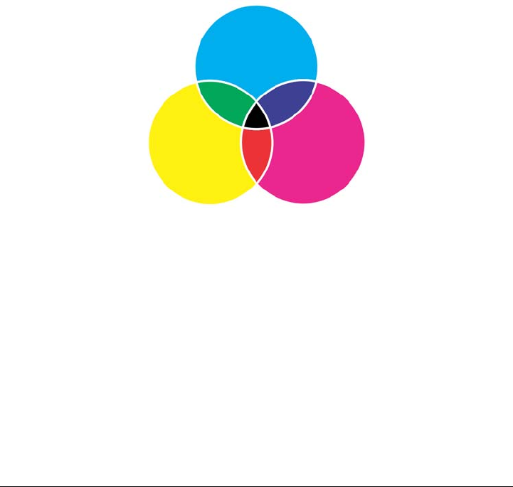
334 Corel DESIGNER X6 User Guide
CMYK color model
The CMYK color model, which is used in printing, uses the components cyan (C),
magenta (M), yellow (Y), and black (K) to define color. Values for these components
range from 0 to 100 and represent percentages.
In subtractive color models, such as CMYK, color (that is, ink) is added to a surface,
such as white paper. The color then “subtracts” brightness from the surface. When the
value of each color component (C,M,Y) is 100, the resulting color is black. When the
value of each component is 0, no color is added to the surface, so the surface itself is
revealed — in this case, the white paper. Black (K) is included in the color model for
printing purposes because black ink is more neutral and darker than blending equal
amounts of cyan, magenta, and yellow. Black ink produces sharper results, especially for
printed text. In addition, black ink is usually less expensive than using colored ink.
Black is the result of combining the three CMY colors at their highest
intensities.
RGB color model
The RGB color model uses the components red (R), green (G), and blue (B) to define
the amounts of red, green, and blue light in a given color. In a 24-bit image, each
component is expressed as a number from 0 to 255. In an image with a higher bit rate,
such as a 48-bit image, the value range is greater. The combination of these components
defines a single color.
In additive color models, such as RGB, color is produced from transmitted light. RGB
is therefore used on monitors, where red, blue, and green lights are blended in various
ways to reproduce a wide range of colors. When red, blue, and green lights are
combined at their maximum intensities, the eye perceives the resulting color as white.
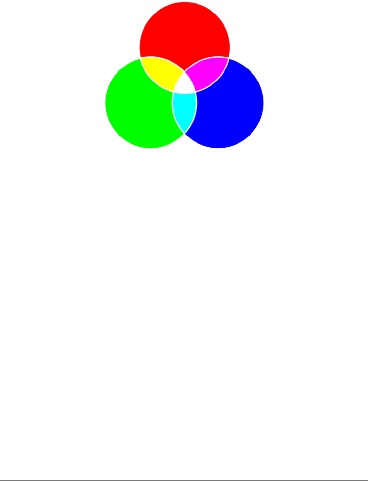
Working with color 335
In theory, the colors are still red, green, and blue, but the pixels on a monitor are too
close together for the eye to differentiate the three colors. When the value of each
component is 0, which signifies an absence of light, the eye perceives the color as black.
White is the result of combining the three RGB colors at their maximum
intensities.
RGB is the most commonly used color model, because it allows a broad range of colors
to be stored and displayed.
HSB color model
The HSB color model uses hue (H), saturation (S), and brightness (B) as components
for defining color. HSB is also known as HSV (with the components hue, saturation,
and value). Hue describes the pigment of a color and is expressed in degrees to represent
the location on the standard color wheel. For example, red is 0 degrees, yellow is 60
degrees, green is 120 degrees, cyan is 180 degrees, blue is 240 degrees, and magenta is
300 degrees.
Saturation describes the vividness or dullness of a color. Values of saturation range from
0 to 100 and represent percentages (the higher the value, the more vivid the color).
Brightness describes the amount of white in the color. Like saturation values, brightness
values range from 0 to 100 and represent percentages (the higher the value, the brighter
the color).
336 Corel DESIGNER X6 User Guide
HSB color model
Grayscale color model
The grayscale color model defines color by using only one component, lightness, which
is measured in values ranging from 0 to 255. Each grayscale color has equal values of
the red, green, and blue components of the RGB color model. Changing a color photo
to grayscale creates a black-and-white photo.
Grayscale color model
Understanding color depth
Color depth refers to the maximum number of colors an image can contain. Color depth
is determined by the bit depth of an image (the number of binary bits that define the

Working with color 337
shade or color of each pixel in a bitmap). For example, a pixel with a bit depth of 1 can
have two values: black and white. The greater the bit depth, the more colors an image
can contain, and the more accurate the color representation is. For example, an 8-bit
GIF image can contain up to 256 colors, but a 24-bit JPEG image can contain
approximately 16 million colors.
Usually, RGB, grayscale, and CMYK images contain 8 bits of data per color channel.
That is why an RGB image is often referred to as 24-bit RGB (8 bits x 3 channels), a
grayscale image is referred to as 8-bit grayscale (8 bits x channel), and a CMYK image
is referred to as 32-bit CMYK (8 bits x 4 channels).
Regardless of how many colors an image contains, the image displayed onscreen is
limited to the highest number of colors supported by the monitor on which it is viewed.
For example, an 8-bit monitor can display only up to 256 colors in a 24-bit image.
Choosing colors
You can choose fill and outline colors by selecting a color from the Document palette,
custom color palettes, palettes from the Palette libraries, color viewers, or color blends.
When you want to use a color that already exists in an object or document, you can
sample the color by using the Color eyedropper tool to achieve an exact match.
For information about applying the colors you choose, see “Applying uniform fills” on
page 361 and “Formatting lines and outlines” on page 157. For information about
saving colors for future use, see “Working with color styles” on page 581.
Default color palette
A color palette is a collection of color swatches. In some programs, color palettes are
known as “swatch palettes.”
In Corel DESIGNER, the default color palette is based on the primary color mode of
the document. For example, if the document’s primary color model is RGB, the default
color palette is also RGB. For more information, see “Understanding color models” on
page 333. You choose the default color model when you create a new drawing. You can
open and use additional color palettes at any time.
You can choose both fill and outline colors by using the default color palette. The
selected fill and outline colors appear in the color swatches on the status bar.
338 Corel DESIGNER X6 User Guide
Document palette
When you create a new drawing, the application automatically generates an empty
palette, called the Document palette. It helps you keep track of the colors that you use
by storing them with your document for future use. For more information, see “Using
the Document palette” on page 346.
Palette libraries and custom color palettes
The color palettes that are found in the Palette libraries cannot be edited directly. Some
of them are provided by third-party manufacturers, for example PANTONE, HKS®
Colors, and TRUMATCH. It may be useful to have on hand a manufacturer’s swatch
book, which is a collection of color samples that shows exactly what each color looks like
when printed.
The PANTONE solid coated palette is an example of a color palette from the
Palette libraries.
Some palettes found in the Palette libraries — PANTONE, HKS Colors, TOYO®,
DIC®, Focoltone, and SpectraMaster® — are collections of spot colors. If you create
color separations when you print, each spot color requires a separate printing plate,
which can significantly affect the cost of the printing job. If you want to use color
separations but would like to avoid using spot colors, you can convert the spot colors to
Working with color 339
process colors when printing. For more information, see “Printing color separations” on
page 727.
Custom color palettes can include colors from any color model, including palettes from
the Palette libraries, such as a spot color palette. You can save a custom color palette for
future use. For more information about working with custom color palettes, see
“Creating and editing custom color palettes” on page 350 and “Organizing and
displaying color palettes” on page 354.
Sampling colors
When you want to use a color that already exists in a drawing, palette, or on your
desktop, you can sample the color to achieve an exact match. By default, you sample a
single pixel from the drawing window.
Color viewers
Color viewers provide a representation of a range of colors by using either one-
dimensional or three-dimensional shapes. The default color viewer is based on the HSB
color model, but you can use this viewer to choose CMYK, CMY, or RGB colors. For
information about color models, see “Understanding color models” on page 333.
An example of a color viewer
340 Corel DESIGNER X6 User Guide
Color blends
When you choose a color by using color blends, you combine base colors to produce the
color you want. The color blender displays a grid of colors that it creates from the four
base colors you choose.
An example of color blends
Choosing Web colors
You can use Web colors when you design documents that will be published to the Web.
With Corel DESIGNER, you can define Web colors by using RGB hexadecimal values
(for example, #aa003f).
To choose a color by using the default color palette
To Do the following
Choose a fill color for a selected object Click a color swatch.
Choose an outline color for a selected object Right-click a color swatch.
Choose from different shades of a color Click and hold a color swatch to display a
pop-up color picker, and then click a color.
View more colors on the default color palette Click the scroll arrows at the top and bottom
of the color palette.
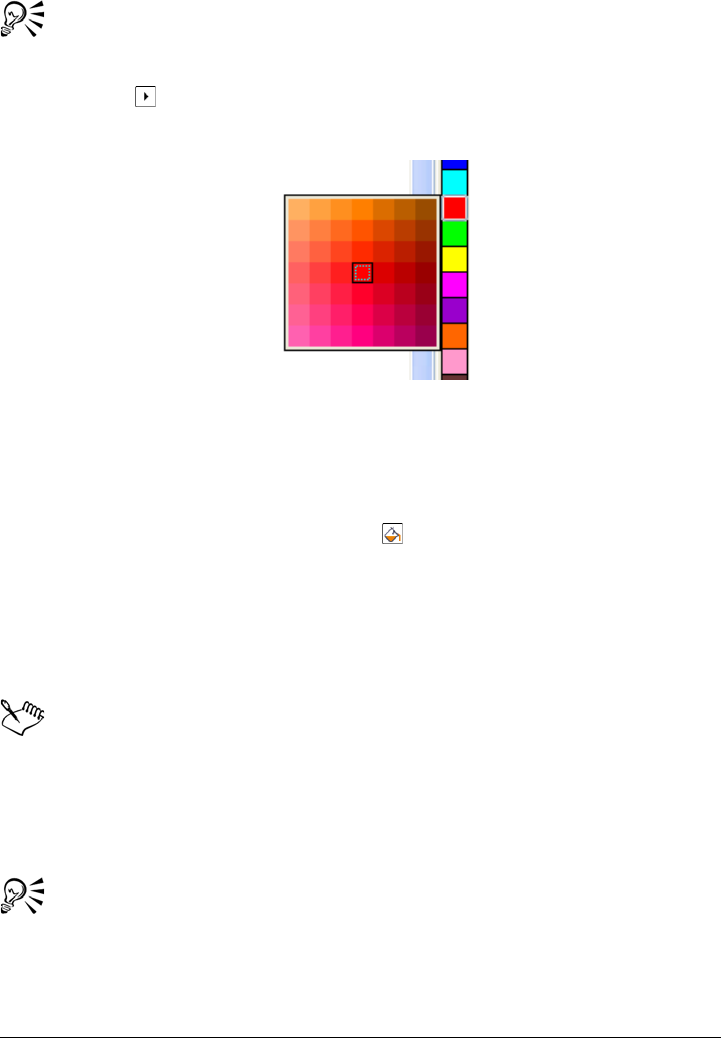
Working with color 341
You can display color values by pointing to a swatch.
To display color names instead of color values, click the Options flyout
button at the top of the default palette, and click Show color names. This
action undocks the default color palette and displays the color names.
An example of a pop-up color palette
To choose a color by using a color palette
1Select an object.
2On the property bar, click the Fill button , and click Fill color dialog.
3Click the Palettes tab.
4Choose a color palette from the Palette list box.
5Move the color slider to set the range of colors displayed in the color selection area.
6Click a color in the color selection area.
Each spot color swatch on a color palette is marked with a small white square.
You should use the same color model for all colors in a drawing; the colors will
be consistent and you will be able to predict the colors of the final output more
accurately. For more information about reproducing colors accurately, see
“Using color management” on page 385.
You can display or hide the names of colors in the fill dialog boxes by clicking
Options and choosing Show color names.
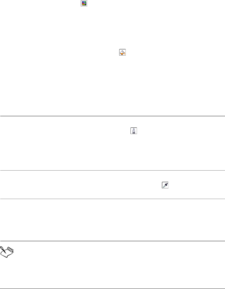
342 Corel DESIGNER X6 User Guide
You can swap the Old color (of the selected object) and the New color (which
has been chosen in the color selection area) by clicking Options and choosing
Swap colors.
You can also access color palettes in the Color docker by clicking the Show
color palettes button and choosing a palette from the list box. If the Color
docker is not open, click Window Color.
To choose a color by using a color viewer
1Select an object.
2On the property bar, click the Fill button , and click Fill color dialog.
3On the Models page, choose a color model from the Model list box.
4Click Options, choose Color viewers, and click a color viewer.
5Move the color slider.
6Click a color in the color selection area.
If you choose a color that is out of the printer’s gamut, Corel DESIGNER
allows you to replace it with a similar color that is in the printer’s gamut. To
replace the color, click the Bring color into gamut button, which appears to
You can also
Choose an outline color On the property bar, click the Outline pen
button . In the Outline area of the
Outline pen dialog box, choose a color from
the color picker.
If you want to view more color options, click
More to open the Select color dialog box.
Sample a color from the drawing or desktop In the Uniform fill dialog box, click the
Eyedropper button , and click the
drawing or desktop.
Swap colors Click Options, and choose Swap colors.
This swaps the Old color (the current
foreground or background color) and the
New color (which has been chosen in the
color selection area).
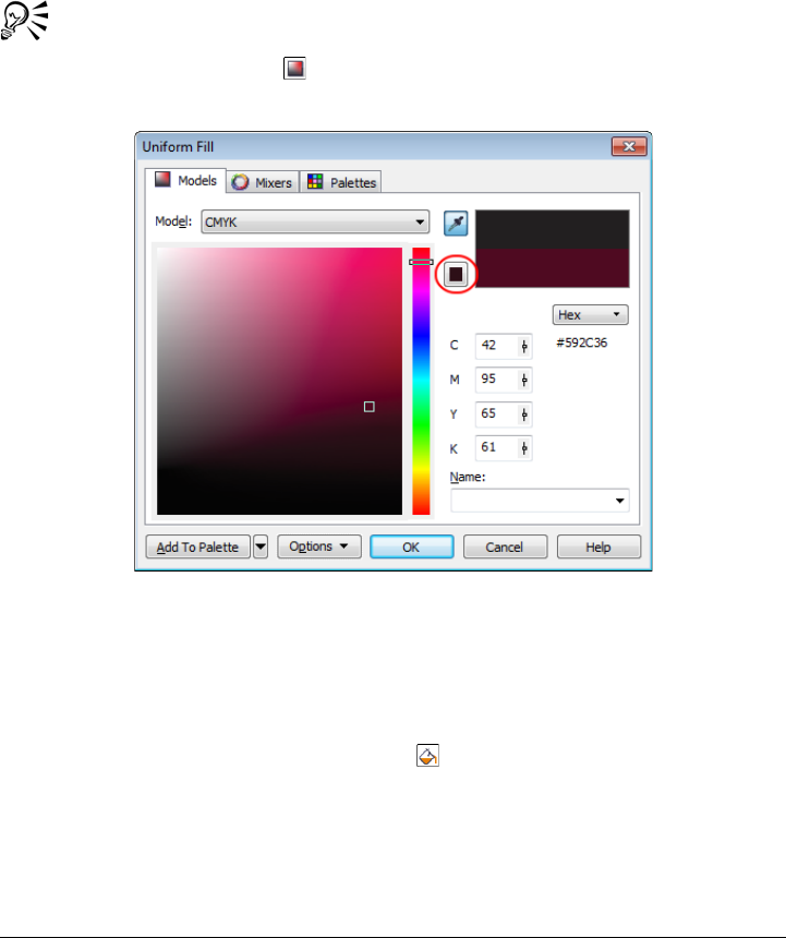
Working with color 343
the left of the New color swatch. For information about color correction, see
“Using color management” on page 385.
You should use the same color model for all colors in a drawing; the colors will
be consistent and you will be able to predict the colors of the final output more
accurately. It is preferable to use the same color model in your drawing that
you will be using for the final output.
You can also access color models in the Color docker by clicking the Show
color viewers button and choosing a color model from the list box. If the
Color docker is not open, click Window Color.
When you choose a color that is out of the printer’s gamut, the Bring color
into gamut button appears below the Eyedropper button.
To choose a color by using color blends
1Select an object.
2On the property bar, click the Fill button , and click Fill color dialog.
3Click the Mixers tab.
4Click Options, choose Mixers, and then click Color blend.
5Open each color picker, and click a color.
6Click a color in the color selection area.
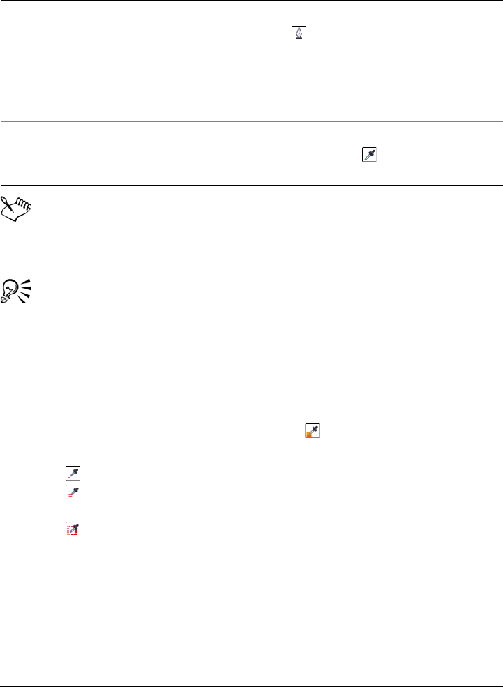
344 Corel DESIGNER X6 User Guide
Only colors that are on the default color palette can be blended. To blend other
colors, you must change the default color palette. For more information, see
“To display or hide a custom color palette” on page 355.
You can change the cell size of the color grid by moving the Size slider.
You can swap the Old color (of the selected object) and the New color (which
has been chosen in the color selection area) by clicking Options and choosing
Swap colors.
To sample a color
1In the toolbox, click the Color eyedropper tool .
2On the property bar, click one of the following buttons:
• 1×1 — lets you choose the color of the pixel you click
• 2×2 — lets you choose the average color in a sample area of 2 × 2 pixels.
The pixel you click is in the middle of the sample area.
• 5×5 — lets you choose the average color in a sample area of 5 × 5 pixels
If you want to sample a color outside the drawing window, click Select from
desktop on the property bar, and click a color on the desktop.
3Click the color that you want to sample.
The Color eyedropper tool automatically switches to the Apply color mode.
4Perform a task from the following table.
You can also
Choose an outline color On the property bar, click the Outline pen
button . In the Outline area of the
Outline pen dialog box, choose a color from
the color picker.
If you want to view more color options, click
More to open the Select color dialog box.
Sample a color from the drawing or desktop In the Uniform fill dialog box, click the
Eyedropper button , and click the
drawing or desktop.
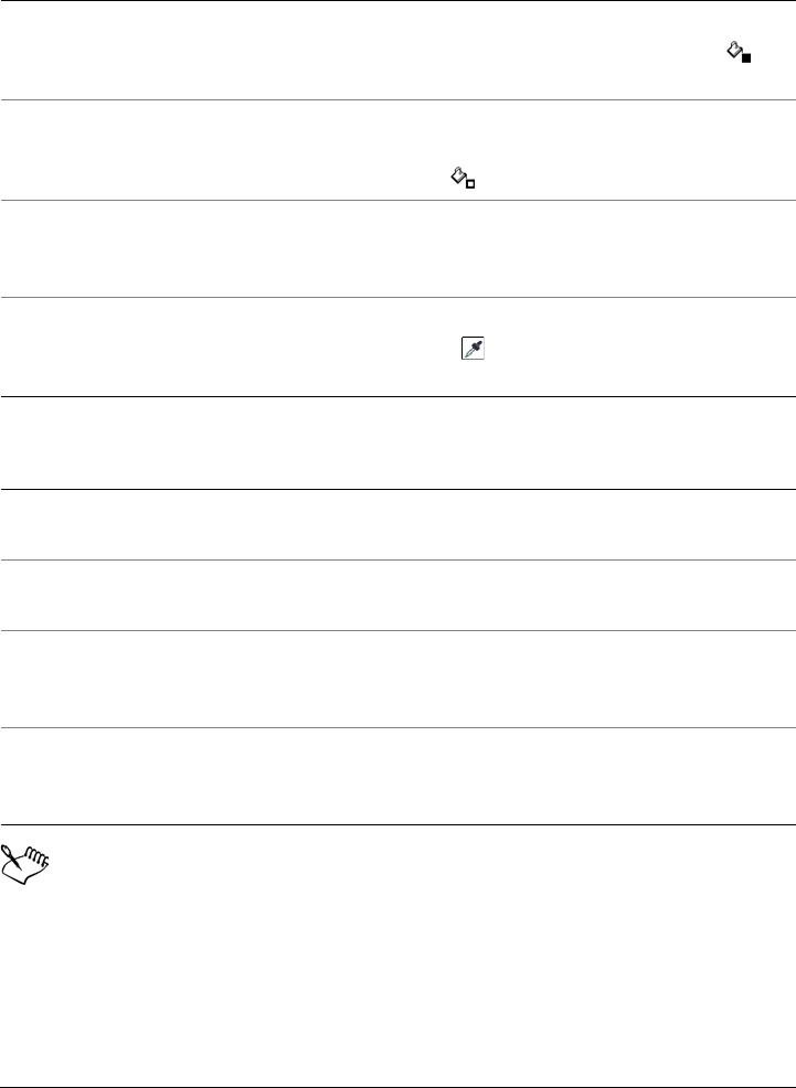
Working with color 345
In some cases, the sampled color may be an RGB or CMYK color that is the
closest equivalent to the original color, rather than being a complete match.
To Do the following
Fill an object with a sampled color Hover over an object. When the Apply color
pointer changes to a solid color swatch ,
click to apply the sampled color.
Fill an object’s outline color with the
sampled color
Hover over an object’s outline. When the
Apply color pointer changes to an outline
shape , click to apply the sampled color.
Add the sampled color to the Document
palette
On the property bar, click the arrow next to
Add to palette, and choose Document
palette.
Sample an additional color On the property bar, click the Select color
button , and then click the color that you
want to sample.
You can also
Drag a sampled color from one object to
another
Drag the color to another object.
Apply a sampled color from the Selected
color swatch on the property bar
Drag the sampled color from the Selected
color swatch to the object.
Apply a sampled color from the Uniform
fill swatch in the lower-right corner of the
drawing window
Drag a color from the Uniform fill swatch
to the object.
Add the sampled color to the Document
palette
Drag the sampled color from the Selected
color swatch or the Uniform fill swatch to
the Document palette.

346 Corel DESIGNER X6 User Guide
To choose a Web color
1Select an object.
2Click Window Color.
3In the Color docker, choose RGB from the list box.
4Type or paste a value in the Hex value box.
Whether you use a three-digit (#fff) or six-digit format (#ffffff), the final value is
presented in the six-digit format.
5Click one of the following buttons:
• Fill — fills the selected object with the new color
• Outline — applies the color to the outline of the object
You can specify hexadecimal color values only when working with RGB colors.
If you type an invalid hexadecimal value, the color does not change.
You can view hexadecimal color values on the status bar.
You can also choose Web colors from the Select color dialog box (on the
property bar, click the Outline pen button, open the color picker in the
Outline pen dialog box, and click More) and the Uniform fill dialog box (on
the property bar, click the Fill button, and choose Fill color dialog), which let
you view and copy the hexadecimal equivalents of non-hexadecimal color
values.
Using the Document palette
When you start a new drawing, an empty color palette, called the Document palette,
appears docked in the lower-left corner of the drawing window. Every time you use a
color in your drawing, it’s automatically added to the Document palette. However, if
you prefer to control which colors are added to the Document palette, you can disable
the automatic updates and add colors manually.
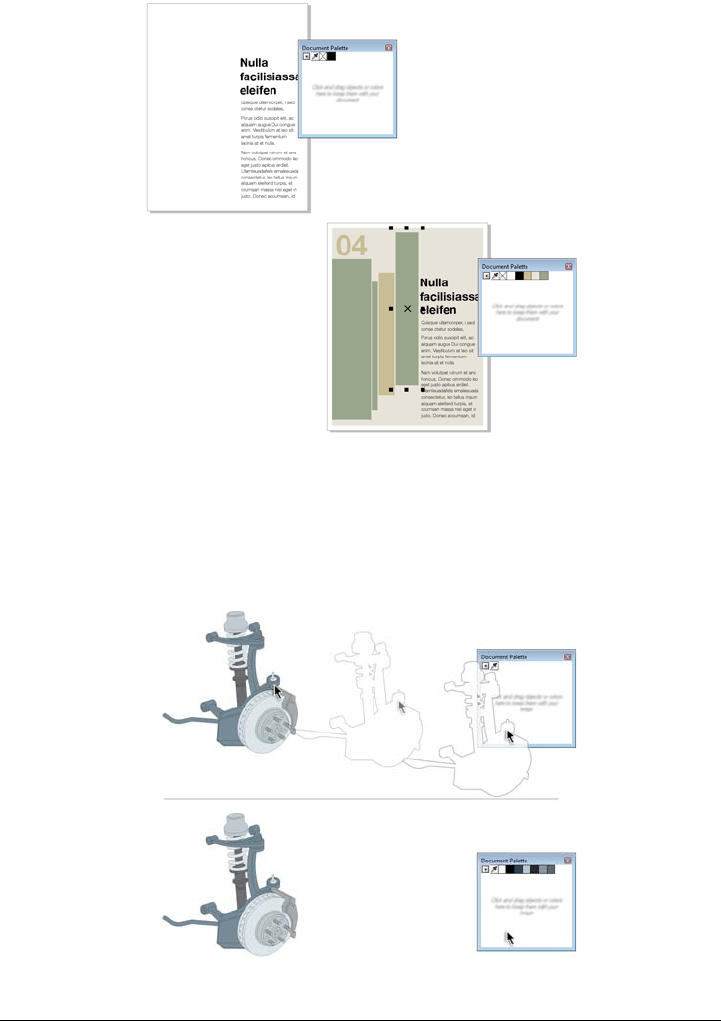
Working with color 347
An example of the Document palette before (above) and after (below) colors are
added to a document.
You can add colors from a color palette, an external image, a color picker, or a color-
related dialog box, such as the Uniform fill dialog box. In addition, you can add colors
from an imported image or object.
Drag a bitmap to the Document palette to add colors.
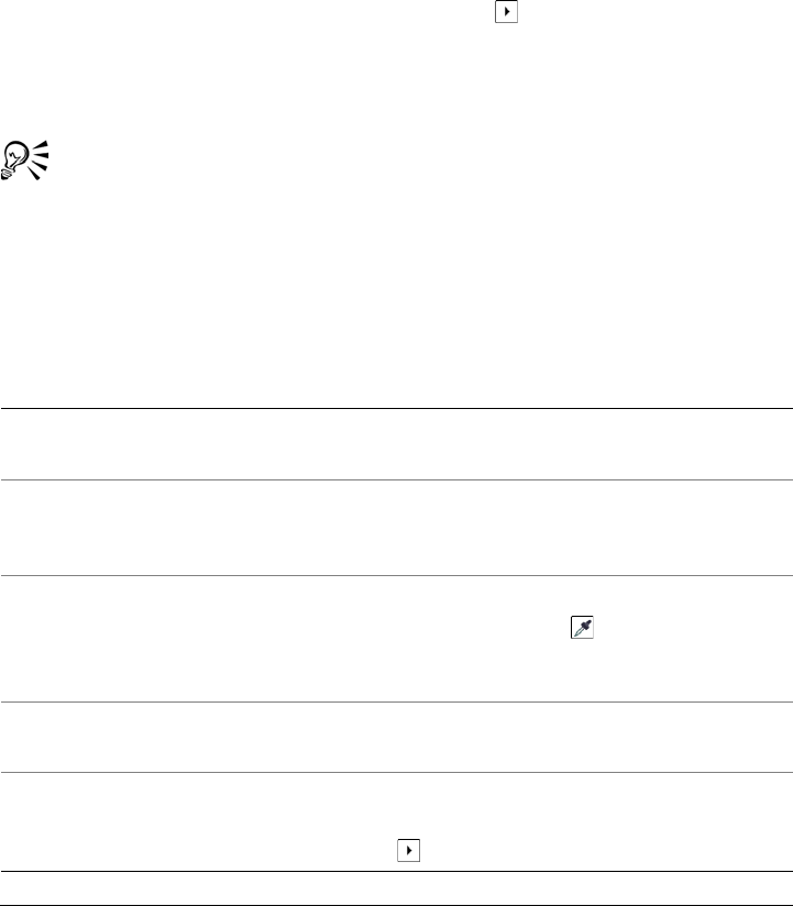
348 Corel DESIGNER X6 User Guide
When you open documents that were created in a previous version of
Corel DESIGNER, only color styles and spot colors are added to the Document palette.
However, you can add all colors from an existing drawing to the Document palette.
You can clear the Document palette of any unwanted or unused colors by removing
colors individually or resetting the palette to remove all unused colors at once.
To disable the automatic adding of color to the Document palette
• On the Document palette, click the flyout button , and click Automatically
update.
By default, the Document palette is docked above the status bar at the bottom of
the application window.
You can also disable the automatic adding of color by clicking To o l s
Customization, clicking Color palette in the Customization list of
categories, and disabling the Automatically update the document palette
check box.
To manually add colors to the Document palette
To Do the following
Add a color from another color palette Drag a color from an open color palette to
the Document palette.
Add a color from a bitmap image On the Document palette, click the
Eyedropper button, and click a color in the
image.
Add multiple colors from an image On the Document palette, click the
Eyedropper button , hold down Ctrl,
and then click the image until you add the
colors that you want.
Add multiple colors from an image or object
by dragging
Drag an image or object from the drawing
window to the Document palette.
Add colors from a selection Select an object or multiple objects. On the
Document palette, click the flyout button
, and click Add from selection.
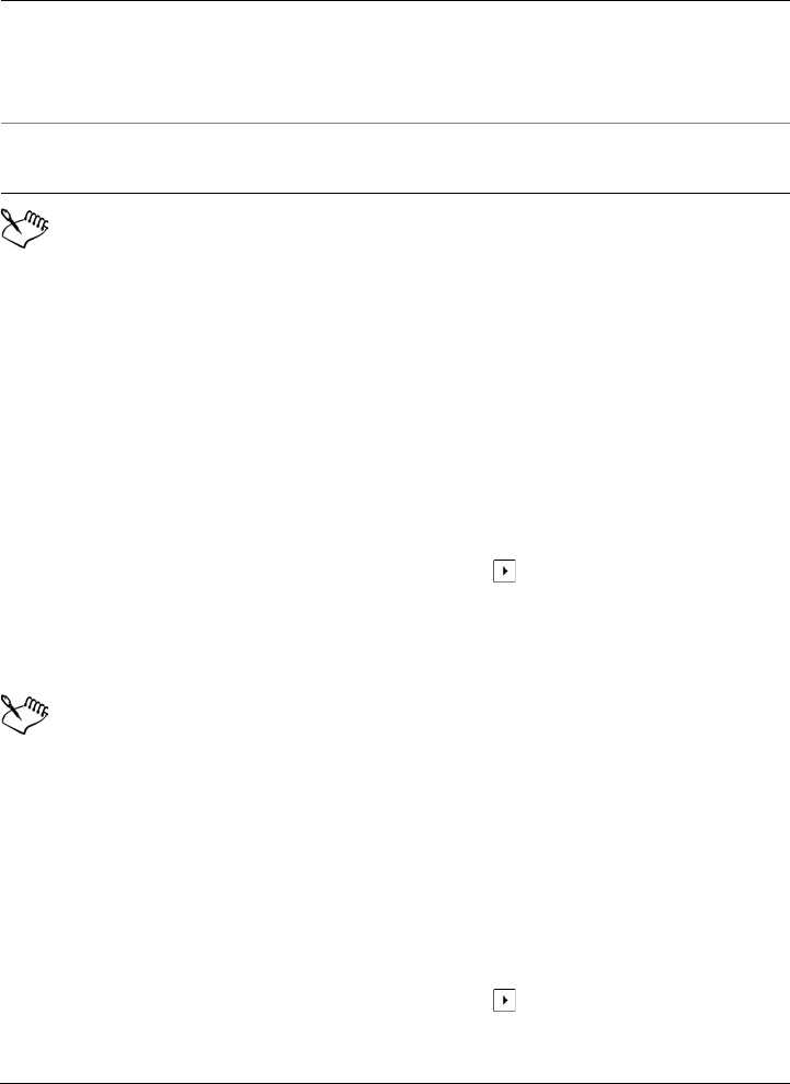
Working with color 349
When dragging most vector objects to the palette, you add all object colors to
the palette. When dragging a bitmap, you can specify the number of colors
that you want to be added to the palette. If an object includes a fountain fill,
texture fill, or pattern fill, only colors that are defined during the fill creation
are supported. Colors from PostScript fills are not supported.
By default, the Document palette is docked above the status bar at the bottom
of the application window.
To add colors from an existing drawing to the Document palette
1Open a drawing.
2On the Document palette, click the flyout button , and click Add from
document.
By default, the Document palette is docked above the status bar at the bottom of
the application window.
If you have a document with both vector and bitmap images, and you want to
add only the colors from the vector images to the Document palette, specify 0
in the Add colors from bitmap dialog box.
If the drawing was created in a previous version of Corel DESIGNER and it
includes custom spot colors, they appear in the Document palette.
To remove a color from the Document palette
1Click a color swatch on the Document palette.
2On the Document palette, click the flyout button , and click Delete color.
Add a color from a color-related dialog box In the dialog box, click a color swatch, click
the arrow next to Add to palette, choose
Document palette, and then click Add to
palette.
Move a color swatch Drag a color swatch to a new position on the
Document palette.
To Do the following

350 Corel DESIGNER X6 User Guide
By default, the Document palette is docked above the status bar at the bottom of
the application window.
You can also remove all colors that are no longer used from the Document
palette by clicking the flyout button , choosing Palette, and clicking Reset
palette.
To reset the Document palette
• On the Document palette, click the flyout button , choose Palette, and click
Reset palette.
By default, the Document palette is docked above the status bar at the bottom of
the application window.
To hide the Document palette
•Click Window Color palettes Document palette.
Hiding the Document palette does not disable the automatic adding of color.
Creating and editing custom color palettes
Custom color palettes are collections of colors or color styles that you save. They can
include colors or color styles from any color model, including spot colors, or any color
palette found in the Palette libraries. You can create a custom palette to store all colors
or color styles that you need in a current, or future, project.
It’s easy to share color palettes with others. The custom palettes are accessible from the
My palettes folder in the Color Palette Manager.
You can create a custom color palette by choosing individual colors or color styles, or by
using the colors in a selected object or an entire document. You can also edit, rename,
and delete custom color palettes.
Custom color palettes are saved as XML files and are stored in the My Documents\My
Palettes folder.
Working with color 351
To create a custom color palette from scratch
1Click Window Color palette manager.
2Click the Creates a new empty color palette button .
3Type a filename in the File name box.
4Click Save.
5In the Color Palette Manager, choose the custom palette that you created.
6Click the Opens the palette editor button .
7In the Palette editor dialog box, click Add color.
8In the Select color dialog box, choose a color, and click Add to palette.
To add a color to a custom color palette
1Open a custom color palette.
2Perform a task from the following table.
You can also
Treat the color as a spot color In the Selected color area of the Palette
editor dialog box, choose Spot from the
Tr e a t a s list.
Treat the color as a process color In the Selected color area of the Palette
editor dialog box, choose Process from the
Tr e a t a s list.
Rename a color Click a color in the color selection area, and
type a name in the Name box.
To Do the following
Add a color from another color palette Drag a color from an open color palette to
the custom palette.
Add a color from an image On the custom palette, click the
Eyedropper button , and click the color
that you want to add.
352 Corel DESIGNER X6 User Guide
When dragging most vector objects to the palette, you add all object colors to
the palette. When dragging a bitmap, you can specify the number of colors
that you want to be added to the palette. If an object includes a fountain fill,
texture fill, or pattern fill, only colors that are defined during the fill creation
are supported. Colors from PostScript fills are not supported.
To create a color palette from an object
1Select an object.
2Click Window Color palettes Create palette from selection.
3Type a filename in the File name box.
4Click Save.
To create a color palette from a document
1Click Window Color palettes Create palette from document.
2Type a filename in the File name box.
Add multiple colors from an image On the custom palette, click the
Eyedropper button , hold down Ctrl,
and click the image until you add the colors
that you want.
Add multiple colors from an image or object Drag an image or object from the drawing
window to the custom palette.
Add a color from a color-related dialog box In the dialog box, click a color swatch, click
the arrow next to Add to palette, choose the
name of your custom palette from the list,
and then click Add to palette.
Add colors from a selection Select an object or multiple objects. On the
custom palette, click the flyout button ,
and click Add from selection.
Move a color swatch Drag a color swatch to a new position on the
palette.
To Do the following

Working with color 353
3Click Save.
To edit a custom color palette
1Click Window Color palettes Palette editor.
2Choose a palette from the list box.
3Perform a task from the following table.
You can delete multiple colors by holding down Shift or Ctrl, clicking the
colors that you want to delete, and clicking Delete color.
To Do the following
Add a color Click Add color. In the Select color dialog
box, click the Models tab, click a color in
the color selection area, and click Add to
palette.
Treat a color as a spot color In the Selected color area of the Palette
editor dialog box, choose Spot from the
Tr e a t a s list.
Treat a color as a process color In the Selected color area of the Palette
editor dialog box, choose Process from the
Tr e a t a s list.
Change a color In the color selection area, click a color, and
click Edit color. In the Select color dialog
box, click the Models tab, and click a new
color in the color selection area.
Delete a color In the color selection area, click a color, and
click Delete color.
Sort colors Click Sort colors, and choose a color sorting
method.
Move a color Drag a color swatch to a new position.
Rename a color Click a color in the color selection area, and
type a name in the Name box.

354 Corel DESIGNER X6 User Guide
If you add a process color to the palette, but treat it as a spot color, the color is
changed to spot and the color name is preserved. However, if you choose a spot
color with a trademarked name, for example a PANTONE color, and convert
it to a process color, the trademarked name is substituted with the color
components for that color.
To rename a custom color palette
1Click Window Color palette manager.
2From the My Palettes folder, right-click a custom palette, and click Rename.
3Type a new name, and press Enter.
To delete a custom color palette
1Click Window Color palette manager.
2From the My Palettes folder, right-click a custom palette, and click Delete.
Organizing and displaying color palettes
The Color Palette Manager is a docker that lets you quickly access the available color
palettes, including the Document palette and the Color Styles palette, and create
custom color palettes. The color palettes in the Color Palette Manager are divided into
two main folders: My palettes and Palette libraries.
Color Palette Manager
Working with color 355
You can use the My palettes folder to store all the custom color palettes that you create.
You can add folders to store and organize your color palettes for different projects. You
can also copy a color palette or move it to a different folder. You can open and control
the display of all color palettes.
The Palette libraries folder of the Color Palette Manager contains collections of preset
color palettes from which you can choose colors. You cannot edit any of the color
palettes that are found in the Palette libraries folder. However, you can create a custom
color palette by copying a color palette from the Palette libraries folder. For more
information, see “Displaying or hiding color palettes in the Palette libraries” on
page 356.
To open the Color Palette Manager
•Click Window Color palette manager.
To display or hide a custom color palette
1Open the Color Palette Manager.
2In the My palettes folder, click the Show or hide icon beside the custom
palette name.
If you want to set a custom color palette as the default palette, click the custom
palette flyout button , and click Set as default.
To open a custom color palette
1Open the Color Palette Manager.
2Click the Opens a palette button .
3Choose the drive and folder where the custom color palette is stored.
If you want to open a color palette (.cpl file) that was created in a previous version
of Corel DESIGNER, select Legacy custom palette (*.cpl) from the Files of type
list box.
4Click the custom palette.
5Click Open.
356 Corel DESIGNER X6 User Guide
If the custom color palette (.xml) was saved to the My palettes folder, you can
open it by clicking Window Color palettes and choosing the custom palette
from the list.
When you open a legacy custom palette (.cpl) file, it is automatically converted
to the XML format (.xml). The XML version is stored in the x:\Documents
and Settings\your name\My Documents folder, and also appears in the My
palettes folder in the Color Palette Manager.
To create a folder for storing custom color palettes
1Open the Color Palette Manager.
2Click the Create a new folder button .
3Type a new name, and press Enter.
If you want to move a custom color palette, drag it to the new folder.
To cut or copy a custom color palette
1Open the Color Palette Manager.
2In the My palettes folder, right-click a custom palette, and click one of the
following:
• Cut
• Copy
If you want to paste the custom palette to a different folder, right-click the folder,
and click Paste.
To copy a palette from the Palette libraries for editing
1Open the Color Palette Manager.
2Drag a palette from the Palette libraries folder to the My palettes folder.
An editable copy of the color palette appears in the My palettes folder.
Displaying or hiding color palettes in the Palette libraries
The Palette libraries contain a collection of color palettes. You can control the display of
the default color palettes, such as the default RGB and default CMYK color palettes.
The main Palette libraries that are included are Process color and Spot color.
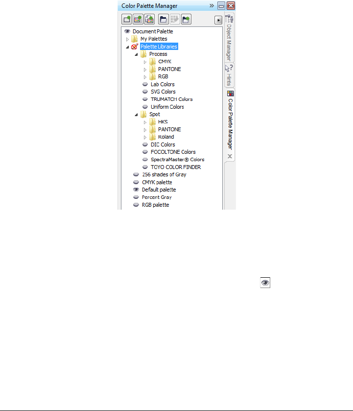
Working with color 357
The Process color library contains the default RGB, CMYK, and Grayscale color
palettes. In addition, you can find preset color palettes that have a specific theme, such
as nature. The Spot color library contains color palettes that are provided by third-party
manufacturers, such as HKS Colors, PANTONE, Focoltone, and TOYO. These color
palettes can be very useful when you need specific company-approved colors for your
printed projects. The color palette libraries are locked, which means that you cannot
edit them.
Palette libraries
To display a color palette in the Palette libraries
1Open the Color Palette Manager.
2In the Palette libraries folder, click the Show or hide icon beside the color
palette name.
To display spot or process color palettes
1Open the Color Palette Manager.
2In the Palette libraries folder, double-click one of the following folders:
• Spot
• Process
358 Corel DESIGNER X6 User Guide
3Click the Show or hide icon beside the color palette name.
Setting the properties of color palettes
You can customize color palettes.
Color palettes can be either docked or floating. Docking a color palette attaches it to
the edge of the application window. Undocking a color palette pulls it away from the
edge of the application window, so it floats and can be easily moved around.
With color swatches, you can set the right mouse button either to display a context
menu or to set the outline color. You can also adjust the color swatch border and size,
and you can hide or display the No color well.
To dock or undock a color palette
You can also change the number of rows on a docked color palette by clicking
To o l s Customization, clicking Color palette in the Customization list of
categories, and typing a value in the Maximum palette rows when docked
box. You can set a maximum of seven rows on a color palette.
To set the action of the right mouse button for color swatches
1Click To o l s Customization.
2In the Customization list of categories, click Color palette.
To Do the following
Dock a color palette Click the top of the color palette border, and
drag the color palette to any edge of the
application window until a thin black
toolbar outline appears.
Undock a color palette Click the dotted border of the color palette,
and drag the color palette away from the
edge of the application window.
Change the number of rows on a docked
color palette
On the palette, click the flyout button ,
click Rows, and choose an option from the
list.

Working with color 359
3Enable one of the following check boxes:
• Context menu
• Set outline color
If you enable Set outline color, you can still display the context menu by
right-clicking anywhere on the border of a color palette.
To customize color swatches
1Click To o l s Customization.
2In the Customization list of categories, click Color palette.
3Enable or disable any of the following check boxes:
• Wide borders
• Large swatches
• Show “no color” well
You can also display color names in the color swatches by clicking the flyout
button on a color palette and clicking Show color names.

Filling objects 361
Filling objects
You can add colored, patterned, textured, and other fills to the inside of objects. You
can customize a fill and set it as a default, so that each object you draw has the same
fill.
This section contains the following topics:
• Applying uniform fills
• Applying fountain fills
• Applying hatch fills
• Applying pattern fills
• Applying texture fills
• Applying PostScript texture fills
• Applying mesh fills
• Applying fills to areas
•Working with fills
Applying uniform fills
You can apply a uniform fill to objects. Uniform fills are solid colors you can choose or
create using color models and color palettes. For information about creating colors, see
“Working with color” on page 333.
To apply a uniform fill
1Select an object.
2Click a color on the color palette.
If you want to mix colors in a uniform fill, press Ctrl and click another color on the
color palette.

362 Corel DESIGNER X6 User Guide
You can also choose a uniform fill by clicking
•the Uniform fill button in the Fill section of the Property
manager docker
•the Interactive fill tools button in the toolbox, clicking the Fountain
fill tool , and choosing Uniform fill from the Fill type list box on
the property bar.
Applying fountain fills
A fountain fill is a smooth progression of two or more colors that adds depth to an
object. Fountain fills are also known as gradient fills.
There are four types of fountain fills: linear, radial, conical, and square. A linear fountain
fill flows in a straight line across the object, a conical fountain fill creates the illusion of
light hitting a cone, a radial fountain fill radiates from the center of the object, and a
square fountain fill is dispersed in concentric squares from the center of the object.
You can apply preset fountain fills, two-color fountain fills, and custom fountain fills to
objects. Custom fountain fills can contain two or more colors, which you can position
anywhere in the fill’s progression. After you create a custom fountain fill, you can save
it as a preset.
When you apply a fountain fill, you can specify attributes for the fill type you choose,
such as the direction of a fill’s color blend, the fill’s angle, center point, midpoint, and
edge pad. You can also adjust the print and display quality of the fountain fill by
specifying the number of fountain steps. By default, the fountain step setting is locked
so that the print quality of the fountain fill is determined by the value specified in the
print settings and the display quality is determined by the default value you set.
However, you can unlock the fountain steps setting and specify a value that applies to
both the print and view quality of the fill. For information about setting fountain fill
steps for printing, see “Fine-tuning print jobs” on page 704.
To apply a preset fountain fill
1Select an object.
2Click Edit Property manager.
3In the Property manager docker, click the Fountain fill button to display
fountain fill options.
Filling objects 363
4Select a fountain fill type.
5Click the arrow button to display more fill options.
6Choose a fill from the Fill presets list box.
You can add a color to a fountain fill by clicking the Interactive fill tools
button in the toolbox, clicking the Fountain fill tool , and dragging a color
from the color palette to an object’s interactive vector handle.
To apply a two-color fountain fill
1Select an object.
2Click Edit Property manager.
3In the Property manager docker, click the Fountain fill button to display
fountain fill options.
4Select a fountain fill type.
5Enable the Two-color blend option.
6Open the From color picker, and click a color.
7Open the To color picker, and click a color.
8Move the fill midpoint slider to adjust the color progression between the start and
end fill colors.
9Click the arrow button to display more fill options.
10 Specify the settings you want.
You can also apply a two-color fountain fill by clicking the Interactive fill
tools button in the toolbox, clicking the Fountain fill tool , and choosing a
fountain fill from the Fill type list box on the property bar.
You can mix colors in a two-color fountain fill by clicking the Fountain fill
tool, selecting one of the interactive vector handles, pressing Ctrl, and clicking
a color on the color palette. You can replace a color in a fountain fill by
dragging a color from the color palette to an object’s interactive vector handle.
To apply a custom fountain fill
1Select an object.

364 Corel DESIGNER X6 User Guide
2Click Edit Property manager.
3In the Property manager docker, click the Fountain fill button to display
fountain fill options.
4Select a fountain fill type.
5Enable the Custom-color blend option.
6Click the first color swatch above the color band, open the Current color picker,
and click a color on the color palette.
7Click the end color swatch above the color band, open the Current color picker,
and click a color on the color palette.
8To adjust the midpoint between the colors, double-click between the two color
swatches on the color band, and drag the new color swatch.
If you want to specify the exact position of the midpoint, type a value in the
Position box.
9Click the arrow button to display more fill options.
10 Specify the attributes you want.
You can also
Add an intermediate color Click the intermediate color swatch above
the color band, open the Current color
picker, and click a color on the color palette.
Change a color Click the corresponding color swatch above
the color band, open the Current color
picker, and click a color on the color palette.
Delete an intermediate color Double-click the corresponding color
swatch.
Change the position of an intermediate color Drag the color swatch to a new location
above the color band, or type a value in the
Position box.
Specify other fill attributes Click the arrow button at the bottom of
the Fill section to display more fill options,
and specify the attributes you want.
Filling objects 365
You can also click the Interactive fill tools button in the toolbox, click the
Fountain fill tool , and drag colors from the color palette in the document
window onto the object’s interactive vector handles.
To change the fountain fill print and display quality
1Select an object.
2In the toolbox, click the Interactive fill tools button, and click the Fountain fill
tool .
3From the Fill type list box on the property bar, choose one of the following
fountain fills:
• Linear
• Radial
• Conical
• Square
4Click the Lock fountain steps button on the property bar, type a value in the
Fountain steps box, and press Enter.
When the Fountain steps box is locked, the number of steps in the printed
fountain fill is determined by the value specified in the Print dialog box. For
information about setting fountain fill steps for printing, see “Fine-tuning print
jobs” on page 704.
To set the display quality for fountain fills
1Click To o l s Options.
2In the list of categories, double-click Wo rks pa c e, and click Display.
3Type a value in the Preview fountain steps box.
Save the fill as a preset Type a name in the Fill presets box, and
click the Save preset button .
If the Fill presets box is not displayed, click
the arrow button at the bottom of the
Fill section.
You can also
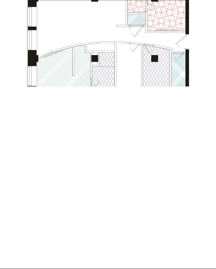
366 Corel DESIGNER X6 User Guide
Applying hatch fills
You can fill objects with hatch patterns to clearly distinguish materials or object
relationships in a drawing. For example, a drawing of a floor plan may use hatching to
indicate different flooring materials, or to indicate where two floors overlap.
Hatch fills can be used to indicate different materials.
Hatch fills are composed of vector-based lines. You can use preset hatch fills or edit fills
by setting different line patterns and colors for the foreground, or by changing the color
of the background. When you edit hatch fills in the Hatch fill dialog box, the changes
apply only to the currently selected object. You can also create new hatch fills and add
them to a library.
When you create new hatch fills, the currently selected fill is used as a starting point. If
no fill is selected, the default fill is used. You can add new lines, specify line style
attributes, set the position and angle for the lines, and control the spacing and offset for
each instance of a line.
You can use hatch fills on projected objects to create the illusion of a three-dimensional
image. Hatch fills use the active drawing plane.
Transforming and scaling hatch fills
Hatch fills can retain their properties independently of changes made to the object, or
they can be transformed and scaled with the object. If you choose to transform the hatch
fill with the object, only the transformations you apply from that point forward are
applied — previous object transformations are not applied to the hatch fill.
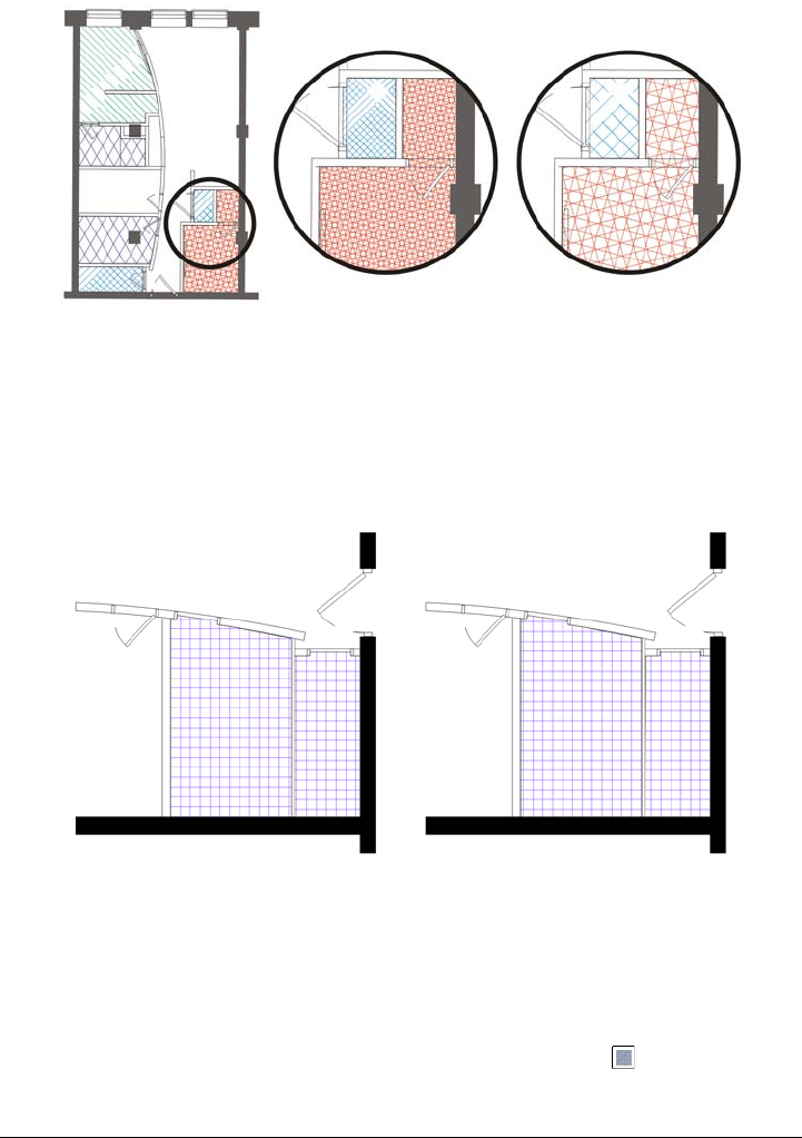
Filling objects 367
The original hatch fill (left) isn’t scaled with the object in the first example
(center) and is scaled with the object in the second example (right).
Aligning hatch fills
When you apply the same hatch fill to more than one object, you can retain the fill
alignment for the individual objects, or you can align the fills.
The hatch fills are aligned in the drawing on the right.
To apply a hatch fill
1Select an object for which you want to apply or edit a hatch fill.
2Click Edit Property manager.
3In the Property manager docker, click the Hatch fill button to display hatch
fill options.
368 Corel DESIGNER X6 User Guide
4Click the Hatch fill properties button .
5In the Hatch fill dialog box, choose a hatch fill library from the Library list box.
6Choose a hatch fill from the Fill picker located below the Library list box.
If a hatch fill is already applied to the selected object, it appears in the Fill picker.
7Specify the attributes you want.
If you want to preview the fill on the object, click Preview.
When you edit a hatch fill in the Hatch fill dialog box, the changes are applied
only to the object selected in the drawing window. Only custom hatch fills
created in the New hatch from selected dialog box can be added to a library.
You can also apply a hatch fill by clicking the Interactive fill tools button in
the toolbox, clicking the Fountain fill tool , choosing Hatch fill from the
Fill type list box on the property bar, and specifying the properties you want.
To Do the following
Change the line color Choose a color from the Front color picker.
Change the background color Choose a color from the Back color picker.
Change line spacing In the Fill area, type a value in the Spacing
box. Larger numbers increase the distance
between lines; smaller numbers decrease the
distance.
Change line width In the Fill area, type a value in the
Thickness box. Larger numbers increase the
line width; smaller numbers decrease the line
width.
Skew lines Type a value in the Skew box to set the
degrees by which the lines are skewed.
Rotate lines Type a value in the Rotate box to set the
degrees by which the lines are rotated.

Filling objects 369
To create a custom hatch fill
1Click Window Property manager.
2In the Property manager docker, click the Hatch fill button to display hatch
fill options.
3Click the Hatch fill properties button .
4In the Hatch fill dialog box, click New hatch.
The new hatch fill is based on the current fill.
5In the New hatch from selected dialog box, click a line to edit from the Hatch
lines list.
The selected line is displayed in red in the Hatch preview window. Unselected
lines are displayed in their applied color.
6In the Line style area, specify the attributes you want.
7In the Line origin area, specify the following:
• y-Origin — lets you set the y-origin for the line. This setting is important if you
have more than one line in the hatch fill. The y-Origin value can be used to set
the spacing between different lines. For example, to ensure that a new line isn’t
positioned directly over an existing line, type a new value in the y-Origin box.
• x-Origin — lets you set the x-origin for the line. This setting is effective when
you have more than one dashed line and you want to offset the patterns of the
different lines. It has no visible effect on standard solid lines.
8In the Line angle box, type a value to set the angle of the line.
9In the Shift box, type a value to offset each instance of a line.
This setting is effective when you have one dashed line and you want to stagger the
pattern. It has no visible effect on standard solid lines.
10 Type a value in the Spacing box to set the distance between two instances of the
line.
The distance between lines is set from the path for the line, not the edge of the
outline. If the Outline width value is high and the Spacing value is low, the lines
might overlap.
11 Repeat steps 5 through 10 for each line you want to edit.
12 Click OK to return to the Hatch fill dialog box, choose a library from the Library
list box, and click Add to library.

370 Corel DESIGNER X6 User Guide
To scale or transform a hatch fill with an object
1Select an object.
2Click Edit Property manager.
3In the Property manager docker, click the Hatch fill button to display hatch
fill options.
4Click the Hatch fill properties button .
5In the Hatch fill dialog box, enable the following options:
• Transform fill with object — automatically transforms the hatch fill to reflect
all future transformations applied to the object
• Scale line width with object — automatically scales hatch lines when the
object is resized
To align hatch fills across multiple objects
1Select two or more objects that have the same hatch fill.
2On the property bar, click the Fill button , and choose Hatch fill dialog.
3Enable the Use world coordinates option.
Applying pattern fills
You can fill objects with two-color, full-color, or bitmap pattern fills.
You can also
Add lines Click the Add button . When you add a
new line, it is created directly over the
previous line. Change the y-Origin value to
view the new line.
Delete lines In the Hatch lines list, choose a line, and
click the Delete button .
Hide or show lines in the Hatch preview
window
In the Hatch lines list, click the Eye icon
to the left of the line name. When the eye
appears closed, the line is hidden. When the
eye appears open, the line is displayed.
Filling objects 371
A two-color pattern fill is composed only of the two colors that you choose. A full-color
pattern fill (also known as “vector pattern”) is a more complex vector graphic that can
be composed of lines and fills. A full-color fill can have color or transparent background.
A bitmap pattern fill is a bitmap image whose complexity is determined by its size,
image resolution, and bit depth.
Corel DESIGNER provides a collection of full-color (vector) and bitmap pattern fills
that you can access and search. You can preview thumbnails of the available pattern fills.
For more information, see “Accessing content” on page 87.
You can also create your own pattern fills. For example, you can create pattern fills from
objects that you draw or images that you import.
You can change the tile size of pattern fills. You can also specify exactly where these fills
begin by setting the tile origin. Corel DESIGNER also lets you offset tiles in a fill.
Adjusting the horizontal or vertical position of the first tile, relative to the top of the
object, affects the rest of the fill.
You can mirror the fill so that alternating tiles are reflections of each other. If you want
a pattern fill to change according to actions you perform on the filled object, you can
set the fill to transform with the object. For example, if you enlarge the object, the
pattern becomes larger while the number of tiles remains the same.
To apply a two-color pattern fill
1Select an object.
2Click Edit Property manager.
3In the Property manager docker, click the Pattern fill button to display
pattern fill options.
4In the Ty p e area, click the Tw o - c o l o r pattern fill button .
5Choose a fill from the Pattern fill picker.
6Open the Front color picker, and click a color.
7Open the Back color picker, and click a color.
You can also mix colors in a two-color pattern fill by pressing Ctrl and clicking
a color on the color palette.
You can also apply a pattern fill by clicking the Interactive fill tools button
in the toolbox, clicking the Fountain fill tool , and choosing Tw o - c o l o r
pattern from the Fill type list box on the property bar. You can drag colors
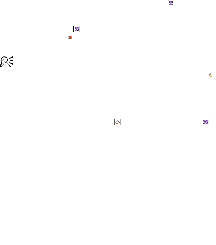
372 Corel DESIGNER X6 User Guide
from the color palette to the interactive handles to change the colors of the fill.
You can mix colors by holding down Ctrl while dragging a color to the
interactive handles.
To apply a full-color or bitmap pattern fill
1Select an object.
2Click Edit Property manager.
3In the Property manager docker, click the Pattern fill button to display
pattern fill options.
4In the Ty p e area, click one of the following buttons:
• Full-color pattern fill
• Bitmap pattern fill
5Choose a fill from the Pattern fill picker.
You can also apply a full-color or a bitmap pattern fill by clicking the
Interactive fill tools button in the toolbox, clicking the Fountain fill tool ,
and choosing an option from the Fill type list box on the property bar.
To create a two-color pattern fill
1Select an object.
2On the property bar, click the Fill button , and choose Pattern fill dialog .
3Enable the 2-color option.
4Open the following color pickers, and click a color:
• Front — to choose a foreground color
• Back — to choose a background color
5Click Create.
6In the Two-color pattern editor dialog box, enable one of the following options in
the Bitmap size area:
• 16 X 16 — changes the resolution of the Edit grid to 16 x 16 squares
• 32 X 32 — changes the resolution of the Edit grid to 32 x 32 squares
• 64 X 64 — changes the resolution of the Edit grid to 64 x 64 squares
7In the Pen size area, enable one of the following options:
• 1 X 1 — changes the pen size to a 1-grid square
• 2 X 2 — changes the pen size to a 2 x 2 square

Filling objects 373
• 4 X 4 — changes the pen size to a 4 x 4 square
• 8 X 8 — changes the pen size to an 8 x 8 square
8Click in the grid to enable a square. If you want to disable a square, right-click the
square.
Squares that are enabled form the foreground, and squares that are disabled form
the background.
You can also create a foreground pattern by dragging in the grid.
To create a two-color pattern fill from an image
1Click To o l s Create Pattern fill.
2Enable the Tw o - c o l o r option.
3In the Resolution area, enable one of the following options:
• Low — creates a low-resolution, two-color pattern
• Medium — creates a medium-resolution, two-color pattern
• High — creates a high-resolution, two-color pattern
4Click OK.
5Select the image or area of the image that you want to use in the pattern.
To create a full-color pattern from an image
1Click To o l s Create Pattern fill.
2Enable the Full-color option.
3Click OK.
4Select the image or area of the image that you want to use in the pattern.
5Click OK in the dialog box that appears.
6In the Save vector pattern dialog box, type a filename for the pattern in the File
name box.
Full-color patterns can have transparent or color background.
To create a pattern fill from an imported image
1Select an object.
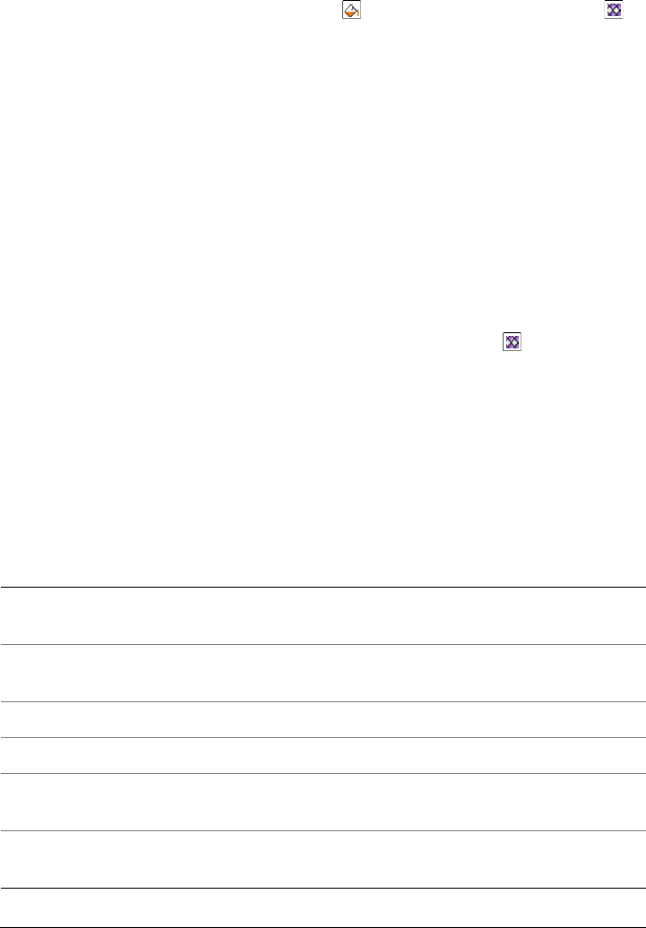
374 Corel DESIGNER X6 User Guide
2On the property bar, click the Fill button , and choose Pattern fill dialog .
3Enable one of the following options:
• 2-color
• Full-color
• Bitmap
4Click Browse.
5In the Import dialog box, locate the image that you want to use, and double-click
the filename.
To change the size of pattern tiles
1Select an object.
2Click Edit Property manager.
3In the Property manager docker, click the Pattern fill button to display
pattern fill options.
4Select a pattern fill type.
5To display more pattern fill options, click the arrow button located below the tile
size buttons.
6Type a value in any of the following boxes:
• Tile width — lets you change the width of a pattern tile
• Tile height — lets you change the height of a pattern tile
You can also
Move the center of the pattern fill up, down,
left, or right
Type values in the X and Y boxes.
Specify a row or column offset as a
percentage of the tile’s width or height
Enable the Row offset or Column offset
option, and type a value in the % of tile box.
Rotate the pattern at a specified angle Type a value in the Rotate pattern box.
Modify the pattern shape Type a value in the Skew pattern box.
Arrange the tiles so that alternating tiles are
reflections of each other
Enable the Mirror fill check box.
Apply object changes to the pattern fill Enable the Transform with object check
box.

Filling objects 375
You can also change the size of pattern tiles by clicking the Interactive fill
tools button in the toolbox, clicking the Fountain fill tool , selecting an
object, and clicking the Small tile, Medium tile, or Large tile button on the
property bar.
You can also skew or rotate tiles by clicking the Interactive fill tools button
in the toolbox, clicking the Fountain fill tool , selecting an object, and
dragging the skewing or rotation handles to change the appearance of the
pattern.
Applying texture fills
A texture fill is a randomly generated fill that you can use to give your objects a natural
appearance. Corel DESIGNER provides preset textures, and each texture has a set of
options that you can change. You can use colors from any color model or palette to
customize texture fills. Texture fills can hold only RGB colors; however, other color
models and palettes can be used as a reference to select colors. For information about
color models, see “Understanding color models” on page 333.
You can change the tile size of texture fills. Increasing the resolution of a texture tile
increases the accuracy of the fill. You can also specify exactly where these fills begin by
setting the tile origin. Corel DESIGNER also lets you offset tiles in a fill. Adjusting the
horizontal or vertical position of the first tile, relative to the top of the object, affects the
rest of the fill.
You can rotate or skew the fill, adjust the tile size, and change the center of the texture
to create a custom fill.
If you want a texture fill to change according to the actions you perform on the filled
object, you can set the fill to transform with the object. For example, if you enlarge the
filled object, the texture becomes larger while the number of tiles remains the same.
Texture fills can enhance a drawing. However, they also increase the size of a file and the
time it takes to print, so you may want to use them in moderation.
To apply a texture fill
1Select an object.
2Click Edit Property manager.

376 Corel DESIGNER X6 User Guide
3In the Property manager docker, click the Texture fill button to display
texture fill options.
4Choose a texture library from the Texture fill list box.
5Choose a texture from the Texture fill picker.
To create a custom texture fill
1Select an object.
2On the property bar, click the Fill button , and choose Texture dialog .
3Choose a texture library from the Texture library list box.
4Choose a texture from the Texture list.
5Specify the settings you want in the texture attributes area.
You can modify the texture you choose from the texture library and save it to
another library, but you cannot save textures to or overwrite textures in the
texture library.
You can also
Change the size of texture tiles Click Tiling, and type values in the Width
and Height boxes.
Move the center of the texture fill up, down,
left, or right
Click Tiling, and type values in the X and Y
boxes in the Origin area.
Specify a row or column offset as a
percentage of the tile’s width or height
Click Tiling, and enable the Row or
Column option. Type a value in the % of
tile size box.
Rotate the texture fill at a specified angle Click Tiling, and type a value in the Rotate
box.
Modify the texture shape Click Tiling, and type a value in the Skew
box.
Apply object changes to the texture fill Click Tiling, and enable the Transform fill
with object check box.
Arrange the tiles so that alternating tiles are
reflections of each other
Click Tiling, and enable the Mirror fill
check box.
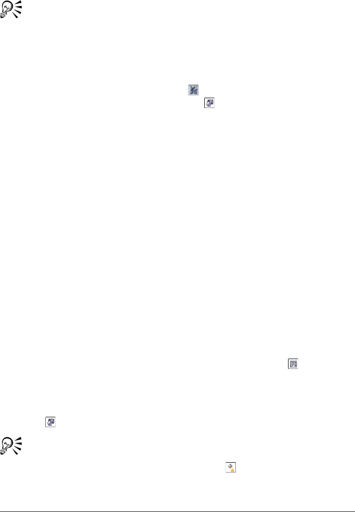
Filling objects 377
You can save a custom texture fill by clicking the plus sign (+) in the Texture
fill dialog box and typing a name in the Texture name box.
You can remove texture tiling by typing “0” in the X and Y boxes in the
Origin area.
You can also edit a texture fill in the Fill section of the Property manager
docker. Click the Texture fill button to display the texture fill options, and
click the Texture fill properties button to open the Texture fill dialog
box. Specify the options you want.
Applying PostScript texture fills
You can apply PostScript texture fills to objects. A PostScript texture fill is created in
the PostScript language. Some textures are very complex, and large objects that contain
PostScript texture fills may take time to print or to update on the screen. Depending on
the view mode you are using, the letters “PS” — rather than the fill — may appear. For
more information about displaying PostScript fills, see “Working with views” on
page 72.
When you apply a PostScript texture fill, you can change several properties, such as the
size, line width, and the amount of gray that appears in the texture’s foreground and
background.
To apply a PostScript texture fill
1Select an object.
2Click Edit Property manager.
3In the Property manager docker, click the Postscript fill button to display
postscript fill options.
4Choose a fill from the PostScript fill textures list box.
If you want to change the fill properties, click the PostScript fill properties
button , and specify the settings you want.
You can also apply a PostScript fill by clicking the Interactive fill tools button
in the toolbox, clicking the Fountain fill tool , choosing PostScript fill
from the Fill type list box on the property bar, and choosing a fill from the
PostScript fill textures list box.
378 Corel DESIGNER X6 User Guide
Applying mesh fills
When you fill an object with a mesh fill, you can create unique effects. For example, you
can create smooth color transitions in any direction without having to create blends or
contours. When you apply a mesh fill, you specify the number of columns and rows in
the grid, and you specify the grid’s intersecting points. After you have created a mesh
object, you can edit the mesh fill grid by adding and removing nodes or intersections.
You can also remove the mesh.
A mesh fill can be applied only to closed objects or a single path. If you want to apply
a mesh fill to a complex object, you must first create a mesh-filled object and combine
it with the complex object to form a PowerClip object. For more information about
working with PowerClip objects, see “Creating PowerClip objects” on page 212.
You can add color to a patch of a mesh fill and to the individual intersection nodes. You
can also choose to mix colors for a more blended appearance.
In addition, you can smooth the color in a mesh fill to reduce the appearance of hard
edges. You can also reveal objects underneath a selected area by applying transparency
to the mesh fill.
To apply a mesh to an object
1Select an object.
2In the toolbox, click the Interactive fill tools button, and click the Mesh fill
tool .
3Type the number of columns in the top portion of the Grid size box on the
property bar.
4Type the number of rows in the bottom portion of the Grid size box on the
property bar, and press Enter.
5Adjust the grid nodes on the object.
You can also
Add a node or an intersection Click once within a grid, and click the Add
intersection button on the property bar.
You can also add a node or an intersection by
double-clicking within a grid.
Filling objects 379
If the mesh object contains color, adjusting the intersection nodes of the mesh
affects how the colors blend together.
You can also marquee select or freehand marquee select nodes to shape an
entire area of the mesh. To marquee select nodes, choose Rectangular from the
Selection mode list box on the property bar, and drag around the nodes that
you want to select. To freehand select nodes, choose Freehand from the
Selection mode list box, and drag around the nodes that you want to select.
Holding down Alt while dragging lets you toggle between the Rectangular
and Freehand selection modes.
You can add an intersection or a node by double-clicking in a space, or you can
add a single line by double-clicking a line.
To fill a mesh with color
1Select a mesh-filled object.
2In the toolbox, click the Interactive fill tools button, and click the Mesh fill
tool .
3Drag a color from the color palette to a patch in the object.
Remove a node or an intersection Click a node, and click the Delete nodes
button on the property bar.
Shape the mesh fill Drag a node to a new location.
Remove the mesh fill Click the Clear mesh button on the
property bar.
You can also
Color a node in a mesh fill Click a node, and click a color on the color
palette.
You can also drag a color from the color
palette to a node.
You can also
380 Corel DESIGNER X6 User Guide
You can also marquee select or freehand marquee select nodes to apply a color
to an entire area of the mesh. To marquee select nodes, choose Rectangular
from the Selection mode list box on the property bar, and drag around the
nodes that you want to select. To freehand select nodes, choose Freehand from
the Selection mode list box on the property bar, and drag around the nodes
that you want to select. Holding down Alt while dragging lets you toggle
between the Rectangular and Freehand selection modes.
To smooth the appearance of color in a mesh fill
1Select a mesh-filled object.
2In the toolbox, click the Interactive fill tools button, and click the Mesh fill
tool .
3Make sure that the Smooth mesh color button on the property bar is enabled.
To apply transparency to a mesh fill
1Select a mesh-filled object.
2In the toolbox, click the Interactive fill tools button, and click the Mesh fill
tool .
3Click a node to select part of the mesh.
4On the property bar, move the Transparency slider to the right to increase the
transparency of the selected area.
Applying fills to areas
You can apply fills to any enclosed area by using the Smart fill tool. Unlike other fill
tools, which fill only objects, the Smart fill tool detects the edges of an area and creates
a closed path so that the area can be filled. For example, if you draw a freehand line that
crosses over itself to create loops, the Smart fill tool can detect the edges of the loops
Mix a color in a mesh fill Select part of the mesh, press Ctrl, and click
a color on the color palette.
You can also
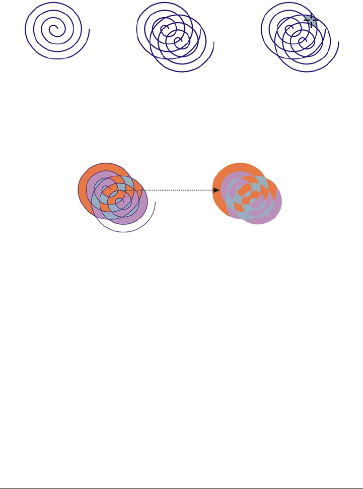
Filling objects 381
and fill them. As long as the paths of one or more objects completely enclose an area, it
can be filled.
In the example above, the original spiral object is duplicated and offset,
resulting in enclosed areas that can be filled by using the Smart fill tool.
Because the Smart fill tool creates a path around the area, it essentially creates a new
object that can be filled, moved, copied, or edited. This means that the tool can be used
in one of two ways: to fill an area or to create a new object from an area.
Although primarily used to fill areas, the Smart fill tool can also be used to
create new objects. In the example above, the original objects — the two spirals
(left) — are deleted (right), but the fill remains because each filled area is
actually an object.
You can apply the default fill and outline to the area, use the property bar to specify a
specific fill color and outline, or create an outline with no fill.
When you use the Smart fill tool on areas that already have fills applied to them,
remember the following:
• An object with transparency applied to it is considered completely transparent —
paths under any area of the object are detected, regardless of whether the specific
area appears opaque.
• PostScript fills are considered transparent — paths under any area of a PostScript
fill are detected.
• All fills other than PostScript fills are considered opaque — paths under these fills
are not detected.

382 Corel DESIGNER X6 User Guide
To apply a fill to an enclosed area
1In the toolbox, click the Interactive fill tools button, and click the Smart fill
tool .
2On the property bar, choose one of the following options from the Fill options list
box:
• Use default — lets you apply the default fill settings
• Specify — lets you fill the area with a solid color by choosing a color from the
Fill color picker on the property bar
• No fill — applies no fill to the area
3From the Outline options box, choose one of the following options:
• Use default — lets you apply the default outline settings
• Specify — lets you choose a line width from the Outline width box and a line
color from the Outline color color picker
• No outline — applies no outline to the area
4Click inside the enclosed area that you want to fill.
A new object is created from the enclosed area, and the selected fill and outline
options on the property bar are applied to it. The new object appears on top of the
existing objects in the layer.
If you click outside an enclosed area, a new object is created from all objects on
the page, and the selected fill and outline options on the property bar are
applied to the new object.
The outline width is centered on an object’s path. Because the Smart fill tool
detects paths, not outlines, thick outlines appear partially covered by the new
object. You can uncover the original outlines by changing the stacking order
of the objects. For information about changing the stacking order of objects,
see “To change the order of objects” on page 268.
Working with fills
There are a number of tasks that are common to all types of fills. You can choose a
default fill color so that every object that you add to a drawing has the same fill. You
can also remove a fill, copy it to another object, or use it to fill an area surrounded by
an open curve.

Filling objects 383
To choose a default fill color
1Click a blank area on the drawing page to deselect all objects.
2Click any rectangle or circle tool.
3On the property bar, click the Fill button , and choose Fill color dialog .
4In the Uniform fill dialog box, specify any fill settings.
You can also change the default fill color by editing the default style sets in the
Object styles docker. For more information, see “Managing default object
properties” on page 576.
To remove a fill
1Select an object.
2Click Edit Property manager.
3In the Property manager docker, click the No fill button .
You cannot remove mesh fills by following this procedure. To remove a mesh
fill from an object, select the object by using the Mesh fill tool , and click
the Clear mesh button on the property bar.
To copy a fill to another object
1Using the Pick tool , select the object from which you want to copy the fill.
2With the right mouse button, drag the object over the destination object to which
you want to apply the fill.
A blue outline of the first object follows the pointer to the destination object.
3When the pointer changes to a crosshair pointer , release the mouse button, and
choose Copy fill here from the context menu.
You can also use the Attributes eyedropper tool to copy a fill. For more
information, see “To copy object properties from one object to another” on
page 253.
You can also sample the color of an existing object and apply the sampled color
to another object as a uniform fill. For more information, see “To sample a
color” on page 344.

384 Corel DESIGNER X6 User Guide
To show fills in open curves
1Click To o l s Options.
2In the list of categories, double-click Document, and click General.
3Enable the Fill open curves check box.

Using color management 385
Using color management
Color management helps ensure colors appear consistent when you work with files
from various sources and output these files on different devices.
This section contains the following topics:
• Understanding color management
• Getting started with color management in Corel DESIGNER
• Installing, loading, and embedding color profiles
• Assigning color profiles
• Converting colors to other color profiles
• Choosing color-conversion settings
• Soft proofing
• Working with color management presets
• Working with color management policies
• Managing colors when opening documents
• Managing colors when importing and pasting files
• Managing colors for print
• Using a safe CMYK workflow
• Managing colors for online viewing
Understanding color management
This section provides answers to the following commonly asked questions about color
management:
• Why don’t colors match?
•What is color management?
• Why do I need color management?
• How do I get started with color management?
• Is my monitor displaying the correct colors?
• Should I assign a color profile or convert colors to a color profile?
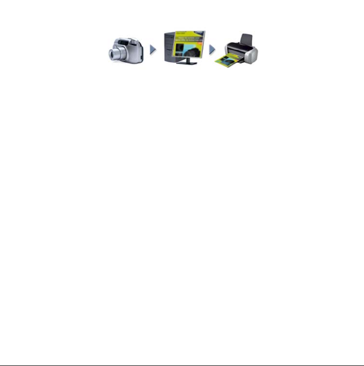
386 Corel DESIGNER X6 User Guide
• What is a rendering intent?
Why don’t colors match?
Different tools are used during the process of creating and sharing a document. For
example, you may start with a file that was created in another application or import an
image that was captured by a digital camera or scanner. After completing the
document, you may print it or email it to a colleague for review. Each of the tools that
you use in your workflow has a different way of interpreting color. In addition, each tool
has its own range of available colors, called a color space, which is a set of numbers that
define how each color is represented.
Example of a document workflow
In other words, when defining and interpreting color, each tool speaks a unique
language. Consider a color in the color space of your digital camera: a vivid blue RGB
color with the values Red = 0, Green = 0, and Blue =255. This color may appear as
a different color in the color space of your monitor. In addition, the color space of your
printer may not contain a match for this color. As a result, when your document moves
through the workflow, this vivid blue color gets lost in the translation and is not
accurately reproduced. A color management system is designed to improve the
communication of color in the workflow so that the color of the output matches your
intended color.

Using color management 387
Colors are defined by their color space. 1. Lab color space. 2. sRGB color space,
displayed against the Lab color space. 3. U.S. Web Coated (SWOP) v2 color
space. 4. ProPhoto RGB color space.
What is color management?
Color management is a process that lets you predict and control color reproduction,
regardless of the source or destination of the document. It ensures a more accurate color
representation when a document is viewed, modified, shared, exported to another
format, or printed.
A color management system, also known as a color engine, uses color profiles to
translate the color values from one source to another. For example, it translates the
colors that are displayed on the monitor into the colors that a printer can reproduce.
Color profiles define the color space of monitors, scanners, digital cameras, printers, and
the applications that you use to create or edit documents.
Why do I need color management?
If your document requires accurate color representation, you may want to learn more
about color management. The complexity of your workflow and the ultimate
destination of your documents are also important considerations. If your documents are
destined only for online viewing, color management may not be as important. However,
if you plan to open documents in another application or if you are creating documents
for print or multiple types of output, then proper color management is essential.
Color management lets you do the following:
• reproduce colors consistently across your workflow, especially when opening
documents that were created in other applications
1
4
3
2

388 Corel DESIGNER X6 User Guide
• reproduce colors consistently when sharing files with others
• preview (or “soft-proof ”) colors before they are sent to their final destination, such
as a printing press, a desktop printer, or the Web
• reduce the need to adjust and correct documents when sending them to different
destinations
A color management system does not offer identical color matching, but it greatly
improves color accuracy.
How do I get started with color management?
Here are some suggestions for adding color management to your workflow:
• Make sure that your monitor is displaying the correct colors. For more information,
see “Is my monitor displaying the correct colors?” on page 388.
• Install color profiles for any input or output devices that you are planning to use.
For more information, see “Installing, loading, and embedding color profiles” on
page 395.
• Become familiar with the color management features of Corel DESIGNER. The
default settings for color management produce good color results, but you can
change these default settings so that they suit your specific workflow. For more
information, see “Getting started with color management in Corel DESIGNER” on
page 391.
• Soft-proof documents to preview final results on-screen. For more information, see
“Soft proofing” on page 400.
• Embed color profiles when saving and exporting files. In this way, you help ensure
color consistency when the files are viewed, modified, or reproduced. For more
information, see “Installing, loading, and embedding color profiles” on page 395.
Is my monitor displaying the correct colors?
Calibrating and profiling the monitor are essential steps for ensuring color accuracy.
When you calibrate a monitor, you set it to display colors according to an established
standard of accuracy. After calibration, you can create a color profile of the monitor,
which describes how the monitor interprets colors. This custom color profile is usually
installed in your operating system by the profiling software, so it can be shared with
other devices and applications. Calibration and profiling work together to achieve color
accuracy: If a monitor is incorrectly calibrated, its color profile is not useful.
Calibration and profiling are complex and usually require third-party calibration
devices, such as colorimeters and specialized software. Furthermore, improper
calibration may do more harm than good. You can learn more about monitor calibration

Using color management 389
and custom color profiles by researching color management techniques and products.
You can also refer to the documentation that was provided with your operating system
or monitor.
How you perceive the color that your monitor displays is also important for managing
color consistency. Your perception is influenced by the environment in which you are
viewing the documents. Here are some ways to create a suitable viewing environment:
• Ensure that your room has a consistent flow of light. For example, if the room is
filled with sunlight, use a shade, or if possible, work in a room without windows.
• Set the monitor background to a neutral color, such as gray, or apply a grayscale
image. Avoid using colorful wallpapers and screensavers.
• Don’t wear bright clothing that can clash with the display of colors on the monitor.
For example, wearing a white shirt reflects onto the monitor and alters your
perception of color.
Should I assign a color profile or convert colors to a color profile?
When you assign a color profile, the color values, or numbers, in the document do not
change. Instead, the application uses the color profile to interpret the document colors.
However, when you convert colors to another color profile, the color values in the
document change.
The best practice is to choose a suitable color space when you create a document and to
use the same color profile throughout your workflow. You should avoid assigning color
profiles and converting colors to other color profiles while working on a document. For
more information, see “Assigning color profiles” on page 398 and “Converting colors to
other color profiles” on page 399.
What is a rendering intent?
A color management system can perform effective translation of document colors to
multiple devices. However, when converting colors from one color space to another, a
color management system may be unable to match certain colors. This translation
failure occurs because some colors in the source may not fit within the range (or gamut)
of the destination color space. For example, the bright red and blue colors that you see
on your monitor are often outside the gamut of colors that your printer can produce.
These “out-of-gamut” colors can dramatically change the look of the document,
depending on how they are interpreted by the color management system. Each color
management system has four methods of interpreting out-of-gamut colors and
mapping them into the gamut of the destination color space. These methods are known

390 Corel DESIGNER X6 User Guide
as “rendering intents.” The choice of a rendering intent depends on the graphical
content of the document.
Many colors in an sRGB document may be out of gamut for the U.S. Web
Coated (SWOP) v2 color space. The out-of-gamut colors are mapped into
gamut according to the rendering intent.
The following rendering intents are available:
•The Relative colorimetric rendering intent is suitable for logos or other graphics
that contain only a few out-of-gamut colors. It matches the out-of-gamut source
colors with the closest in-gamut colors at the destination. This rendering intent
causes the white point to shift. If you print on white paper, the whiteness of the
sRGB color space U.S. Web Coated (SWOP)
v2 color space
Out-of-gamut colors
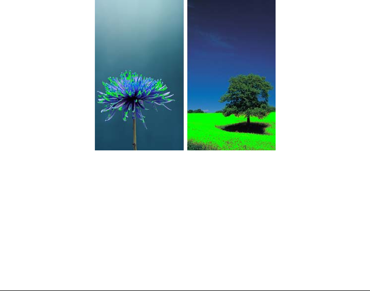
Using color management 391
paper is used to reproduce the white areas of the document. Therefore, this
rendering intent is a good option if your document will be printed.
•The Absolute colorimetric rendering intent is suitable for logos, or other
graphics, that require very precise colors. If no match is found for the source colors,
then the closest possible match is used. The Absolute colorimetric and Relative
colorimetric rendering intents are similar, but the Absolute colorimetric
rendering intent preserves the white point through the conversion and does not
adjust for the whiteness of the paper. This rendering intent is used mainly for
proofing.
•The Perceptual rendering intent is suitable for photographs and bitmaps that
contain many out-of-gamut colors. The overall color appearance is preserved by
changing all the colors, including the in-gamut colors, to fit within the range of
colors at the destination. This rendering intent maintains the relationships between
colors to produce the best results.
•The Saturation rendering intent produces more concentrated solid colors in
business graphics, such as charts and graphs. Colors may be less accurate than those
produced by other rendering intents.
The number of out-of-gamut colors (indicated by the green overlay) may
influence your choice of a rendering intent. Left: The Relative colorimetric
rendering intent is suitable for this photo, which contains only a few
out-of-gamut colors. Right: The Perceptual rendering intent is a good choice
for this photo, which contains many out-of-gamut colors.
Getting started with color management in Corel DESIGNER
Corel DESIGNER has two types of color management settings: default settings for
color management and document color settings. The default settings for color

392 Corel DESIGNER X6 User Guide
management control the colors of new documents and any documents that do not
contain color profiles (also known as “untagged documents”). Documents that were
created in earlier versions of Corel DESIGNER are treated as untagged. Document
color settings affect only the colors of the active document.
Default settings for color management
The default settings for color management are essential for producing consistent colors.
•Presets — If you are new to color management and create designs for a specific
output, you can choose a preset to help you get started with the right color
management settings such as default color profiles and color-conversion settings.
Examples are the North America Prepress preset, which is suitable for projects to
be printed by North American print service providers, and the Europe Web preset,
which is suitable for Web projects that are created in Europe. For more information
about color management presets, see “Working with color management presets” on
page 404.
•Default color profiles — define the RGB, CMYK, and grayscale colors in new
and untagged documents. You can change these settings so that all new documents
use the color profiles that you specify. In some applications, default color profiles
are called “working space profiles.”
•Primary color mode — determines the document color palette that is displayed
when you open or start a document as well as the default color mode of a document
that is exported as a bitmap. The primary color mode is set for all new and
untagged documents, but you can change this setting for the active document in
the Document color settings dialog box. Note that the primary color mode does
not limit colors in a Corel DESIGNER document to a single color mode.
•Rendering intent — lets you choose a method for mapping out-of-gamut colors
in new and untagged documents. If the default rendering intent is not suitable for
the active document, you can change it in the Document color settings dialog
box. For information about choosing the right rendering intent for your projects,
see “What is a rendering intent?” on page 389.
•Color conversion settings — control how colors are matched when you are
converting colors from one color profile to another. For example, you can change
the color engine or specify options for converting pure black colors in RGB,
CMYK, Lab, or Grayscale documents. For more information, see “Choosing color-
conversion settings” on page 399.
•Spot color definition — lets you display spot colors by using their Lab, CMYK,
or RGB color values. These alternative color values are also used when spot colors
are converted to process colors.
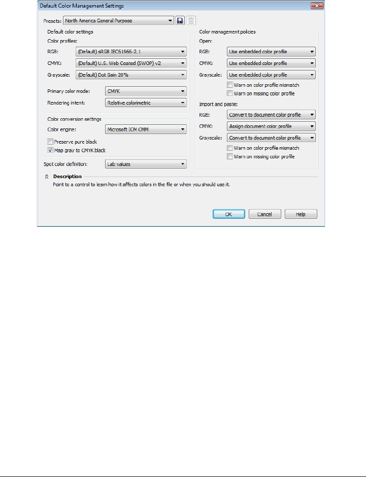
Using color management 393
•Color management policies — manage colors in files that you open, or import or
paste in an active document. For more information about color management
policies, see “Working with color management policies” on page 406.
Default color management settings dialog box
Document color settings
You can view and edit the color settings of the active document, without affecting new
and untagged documents. You can see what color profiles are assigned to the document
as well as what are the default color profiles of the application. The color profiles that
are assigned to an active document determine the document color space for RGB,
CMYK, and grayscale colors.
You can also assign different color profiles to the active document or convert its colors
to specific color profiles. For information about assigning color profiles, see “Assigning
color profiles” on page 398. For information about converting document colors to other
color profiles, see “Converting colors to other color profiles” on page 399.
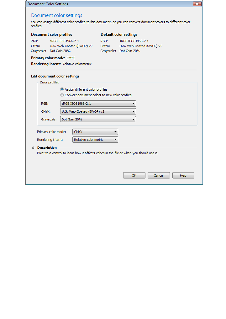
394 Corel DESIGNER X6 User Guide
Document color settings dialog box
In addition, you can change the primary color mode and rendering intent for the active
document.
Getting help
You can find information about each control available in the Default color settings and
Document color settings dialog boxes by pointing to the control and viewing the
description in the Description area.
To access default settings for color management
•Click To o l s Color management Default settings.
Using color management 395
To change the default color profiles
1Click To o l s Color management Default settings.
2In the Default color settings area, choose a color profile from the following list
boxes:
• RGB — describes RGB colors in new and untagged documents
• CMYK — describes CMYK colors in new and untagged documents
• Grayscale — describes grayscale colors in new and untagged documents
To access document color settings
•Click To o l s Color management Document settings.
You can also view the document color settings in the Document properties
dialog box by clicking File Document properties.
The status bar displays the color profiles that are used in the active document.
Installing, loading, and embedding color profiles
To ensure color accuracy, a color management system needs ICC-compliant profiles for
monitors, input devices, external monitors, output devices, and documents.
• Monitor color profiles — define the color space that is used by your monitor to
display document colors. Corel DESIGNER uses the primary monitor profile that
is assigned by the operating system. The monitor profile is very important for color
accuracy. For more information, see “Is my monitor displaying the correct colors?”
on page 388.
You can also
Change the primary color mode Choose a color mode from the Primary
color mode list box.
Changing the primary color mode in the
Default color management settings dialog
box does not affect the active document.
Change the rendering intent Choose a rendering intent from the
Rendering intent list box.

396 Corel DESIGNER X6 User Guide
• Input device color profiles — used by input devices such as scanners and digital
cameras. These color profiles define which colors can be captured by specific input
devices.
• Display color profiles — include monitor profiles that are not associated with your
monitor in the operating system. These color profiles are especially useful for soft-
proofing documents for monitors that are not connected to your computer.
• Output device color profiles — define the color space of output devices such as
desktop printers and printing presses. The color management system uses these
profiles to map accurately document colors to the colors of the output device.
• Document color profiles — define the RGB, CMYK, and grayscale colors of a
document. Documents that contain color profiles are known as “tagged.”
Finding color profiles
Many color profiles are installed with your application or can be generated with
profiling software. Manufacturers of monitors, scanners, digital cameras, and printers
also provide color profiles. In addition, you can access color profiles from Web sites such
as:
• http://www.color.org/findprofile.xalter — This Web site of the International Color
Consortium (ICC) can help you find commonly used standard color profiles.
• http://www.eci.org/doku.php?id=en:downloads — This Web site of the European
Color Initiative (ECI) provides standard ISO profiles as well as profiles that are
specific to Europe
• http://www.tftcentral.co.uk/articles/icc_profiles.htm — This Web site provides
ICC profiles for many different types of LCD (Liquid Crystal Display) monitors to
help you display consistent colors. However, if color accuracy is essential for your
workflow, you should calibrate and profile your monitor instead of relying on
readily available monitor profiles. For more information, see “Is my monitor
displaying the correct colors?” on page 388.
Installing and loading color profiles
If you don’t have the necessary color profile, you can install it, or you can load it within
the application. Installing a color profile adds it to the Color folder of the operating
system; loading a color profile adds it to the Color folder of the application.
CorelDRAW Graphics Suite can access color profiles from both Color folders.
Embedding color profiles
When you save or export a document to a file format that supports color profiles, the
color profiles are embedded in the file by default. Embedding a color profile attaches

Using color management 397
the color profile to the document to ensure that the same colors you used are shared
with anyone who views or prints the document.
To install a color profile
• In Windows Explorer, right-click a color profile, and click Install profile.
To load a color profile
1Click To o l s Color management Default settings.
2In the Default color setting area, choose Load color profiles from the RGB,
CMYK, or Grayscale list boxes.
3In the Open dialog box, navigate to the color profile.
After you load a color profile, you can also access it from the Color proof
settings docker, Print dialog box, and Document color setting dialog box.
Note that you can load a color profile of any color mode from any list box:
RGB, CMYK, or Grayscale. However, after you load the profile, you can
access it only from the list box of the respective color mode. For example, you
can load an RGB color profile from the CMYK list box, but you can access the
profile only from the RGB list box.
You can also load a color profile from the Document color settings dialog
box.
To embed a color profile
1Click File, and then click one of the following commands:
• Save as
• Export
• Export for Web
2In the dialog box that appears, enable the Embed color profiles check box.
When you save or export a file to the Corel DESIGNER (DES) or Adobe
Portable Document Format (PDF) file format, you can embed up to three color
profiles.
398 Corel DESIGNER X6 User Guide
Embedding a color profile increases the file size of a document. To avoid
increasing the file size unnecessarily, Corel DESIGNER embeds only color
profiles for colors that are used in the document. For example, if your
document contains only RGB objects, only the RGB color profile will be
embedded.
Assigning color profiles
When you open or import a document that is missing a color profile, by default the
application automatically assigns a color profile to the document. If the document has
a color profile that is not suitable for the required destination, you can assign a different
color profile to the document. For example, if the document is intended to be displayed
on the Web or to be printed on a desktop printer, you should make sure that sRGB is
the document RGB profile. If the document is destined for print production, the Adobe
RGB (1998) profile is a better choice, because it has a larger gamut and produces good
results when RGB colors are converted to a CMYK color space.
When you assign a different color profile to a document, the colors may appear
different, although the color values do not change.
Left: The SWOP 2006_Coated3v2.icc color profile is assigned to the active
document. Right: When the Japan Color 2002 Newspaper color profile is
assigned to the document, the colors appear much less saturated.
To assign color profiles to a document
1Click To o l s Color management Document settings.

Using color management 399
2In the Edit document color settings area, enable the Assign different color
profiles option.
3Choose color profiles from the RGB, CMYK, and Grayscale list boxes.
Converting colors to other color profiles
When you convert document colors from one color profile to another, the color values
in the document are changed according to the rendering intent, but the appearance of
colors is preserved. The main purpose of converting colors is to match the appearance
of colors in the source color space as closely as possible to colors in the destination color
space.
Because multiple color conversions deteriorate accuracy, it is recommended that you
convert colors only once. Wait until the document is ready and you are sure of the color
profile that will be used for the final output. For example, if you designed a document
in the Adobe® RGB (1998) color space, and the document will be posted on the Web,
you can convert document colors to the sRGB color space.
You can choose the color management engine that is used for converting colors. For
more information, see “Choosing color-conversion settings” on page 399.
To convert colors to other color profiles
1Click To o l s Color management Document settings.
2In the Edit document color settings area, enable the Convert document colors
to new color profiles option.
3Choose a color profile from the RGB, CMYK, and Grayscale list box.
4Choose a suitable rendering intent from the Rendering intent list box. For
information about the available rendering intents, see “What is a rendering
intent?” on page 389.
Choosing color-conversion settings
When you choose color profiles, colors are matched between devices as closely as
possible by the color management module (CMM) of the Microsoft® Image Color
Management (ICM), which is the default CMM. Color management modules are also
known as “color engines.”
400 Corel DESIGNER X6 User Guide
On Windows Vista, you can also use the Windows Color System (WCS) color
management module. In addition, you can use the Adobe® CMM if it is installed on
your computer. To download and install the Adobe CMM, visit the Adobe Web site.
Handling pure black and grayscale colors
You can preserve pure black color in the destination color space during color
conversion. For example, if you are converting an RGB document to a CMYK color
space, pure RGB black (R=0, G=0, B=0) can be mapped to pure black CMYK
colors (K=100). This option is recommended for grayscale documents or documents
that contain mostly text. Note that preserving pure black during color conversion may
create solid edges of black in effects and gradient fills that contain black.
By default, grayscale colors are converted to the CMYK black (K) channel. This
process ensures that all grayscale colors print as shades of black, and no cyan, magenta,
and yellow inks are wasted during printing.
To choose color-conversion settings
1Click To o l s Color management Default settings.
2In the Color conversion settings area, choose a color engine from the Color
engine list box.
Soft proofing
Soft proofing provides an on-screen preview of a document as it will appear when it is
reproduced by a specific printer or displayed on a specific monitor. Unlike the “hard-
proofing” technique that is used in a traditional printing workflow, soft proofing lets
you look at the final result without committing ink to paper. You can verify whether the
color profile of the document is suitable for a specific printer or monitor and avoid
unwanted results.
You can also Do the following
Keep pure black in the source color space as
pure black in the destination color space
Enable the Preserve pure black check box.
Map grayscale colors to CMYK black during
conversion
Enable the Map gray to CMYK black check
box.
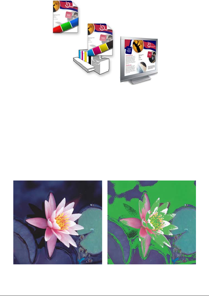
Using color management 401
Top left: An RGB color profile is assigned to the document. Middle and right:
Assigning a specific CMYK profile allows an on-screen simulation of the
printed output.
To simulate the output colors that are produced by a device, you need to choose the
color profile of the device. Because the color spaces of the document and device are
different, some document colors may not have matches in the gamut of the device color
space. You can enable the gamut warning, which lets you preview the on-screen colors
that cannot be reproduced accurately by the device. When the gamut warning is
enabled, an overlay highlights all the out-of-gamut colors for the device that you are
simulating. You can change the color of the out-of-gamut overlay, and you can also
make it more transparent to see the underlying colors.
The gamut warning highlights colors that a printer or monitor cannot
reproduce accurately.

402 Corel DESIGNER X6 User Guide
You can change how out-of-gamut colors are brought into the gamut of the proof profile
by changing the rendering intent. For more information, see “What is a rendering
intent?” on page 389.
You can preserve the RGB, CMYK, or grayscale color values of the document when
soft-proofing. For example, if you are soft-proofing a document to be printed to a
printing press, you can keep the original document CMYK color values in the soft proof.
In this case, all colors will be updated on-screen, but only the RGB and grayscale color
values of the document will be changed in the soft proof. Preserving the CMYK color
values can help you prevent unwanted color conversions in the final output.
If you often need to soft-proof documents for a specific output, you can create and save
custom proof presets. You can delete the presets that you no longer need at any time.
You can save soft proofs by exporting them to the JPEG, TIFF, Adobe Portable
Document Format (PDF), or Corel PHOTO-PAINT (CPT) file format. You can also
print proofs.
By default, soft proofing is disabled when you start a new document or when you open
a document. However, you can make sure that soft proofing is turned on by default at
all times.
To turn soft proofing on or off
•Click To o l s Proof colors.
When you turn soft proofing on, colors in the document window, color
palettes, and preview windows of dialog boxes appear different.
Simulating printer output may cause on-screen colors to appear dull because
all colors are brought into a CMYK color space, which has a smaller gamut
than an RGB color space.
You can also enable or disable soft proofing by clicking the Proof colors
button on the status bar.
To specify soft-proof settings
1Click To o l s Color proof settings.
2Perform any of the following tasks.
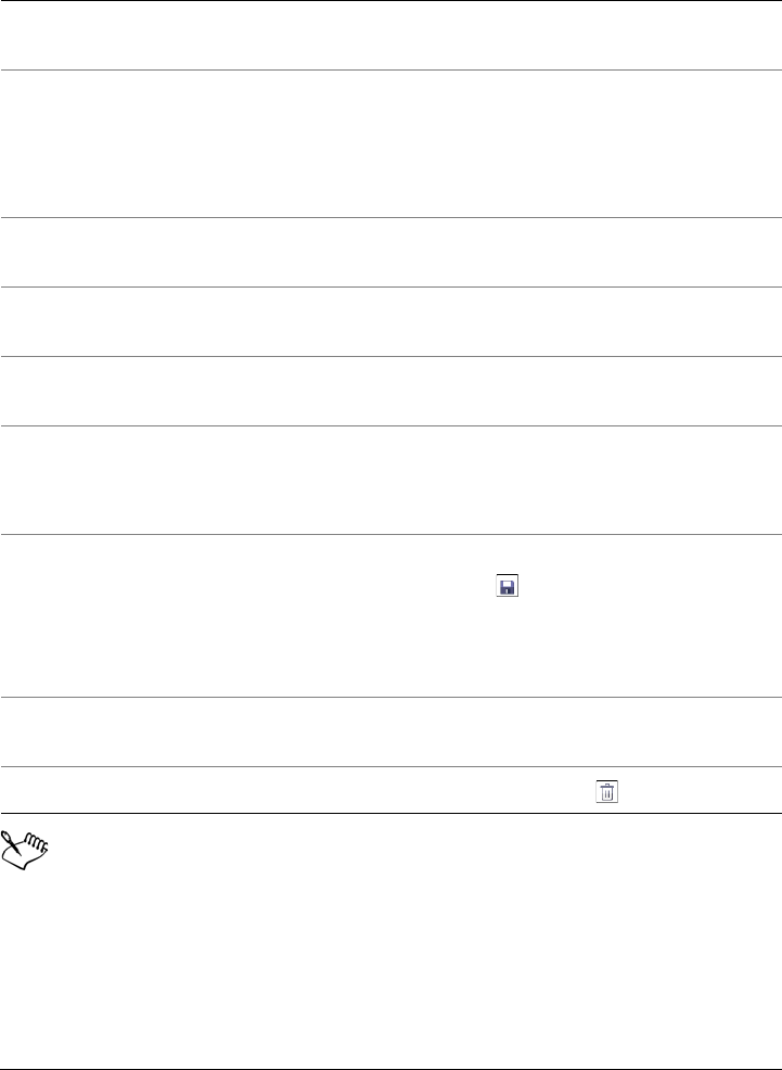
Using color management 403
The accuracy of the simulation depends on factors such as the quality of your
monitor, the color profile of the monitor and the output device, and the
ambient lighting in your work area.
To export a soft proof
1Click To o l s Color proof settings.
To Do the following
Simulate the output of a specific device From the Simulate environment list box,
choose the color profile of the device.
Keep specific color values unchanged Enable the Preserve numbers check box.
Depending on the color profile in the
Simulate environment box, the check box
lets you preserve CMYK, RGB, or grayscale
color values.
Change the rendering intent Choose a rendering intent from the
Rendering intent list box.
Enable the gamut warning In the Gamut warning area, enable the
Out-of-gamut colors check box.
Change the color of the out-of-gamut
overlay
In the Gamut warning area, choose a color
from the color picker.
Change the transparency of the out-of-
gamut overlay
In the Gamut warning area, type a value in
the Transparency box.
The value should be between 1 and 100.
Save a custom proof preset Choose the settings that you want, click the
Save button , and then type a name in the
Save preset as box.
Out-of-gamut settings are not included in
the proof preset.
Choose a proof preset From the Proof preset list box, choose a
preset.
Delete a proof preset Click the Delete button .

404 Corel DESIGNER X6 User Guide
2In the Color proof settings docker, click the Export soft proof button.
3Type a filename in the File name box.
4From the Save as type list box, choose one of the following options:
• JPG - JPEG Bitmaps
• PDF - Adobe Portable Document Format
• TIF - TIFF Bitmap
• CPT - Corel PHOTO-PAINT image
5Choose any settings in the dialog box that appears.
To print a proof
1Click To o l s Color proof settings.
2In the Color proof settings docker, click the Print proof button.
To turn soft proofing on by default
1Click To o l s Options.
2In the Wo rk s pa ce list of categories, click Display.
3Enable the Proof colors by default check box.
Working with color management presets
The application provides color management presets, which are default color settings
that are applied to new and untagged documents. You can choose a color management
preset that is suitable for the geographic region where a document is created or for the
location of its final output.
You can also create your own presets, which allows you to retain your selections in the
Default color management settings dialog box and reuse them in other documents.
If you no longer need a preset, you can delete it.
To choose a color management preset for new documents
1Click To o l s Color management Default settings.
2Choose one of the following color management presets from the Presets list box:
• North America General Purpose — suitable for designs that will be used in
multiple types of output in North America

Using color management 405
• Europe General Purpose — suitable for designs that will be used in multiple
types of output in Europe
• Europe Prepress — suitable for designs that will be printed by print service
providers in Europe
• Europe Web — suitable for Web designs that are created in Europe
• Japan General Purpose — suitable for designs that will be used in multiple
types of output in Japan
• Japan Prepress — suitable for designs that will be printed by print service
providers in Japan
• Japan Web — suitable for Web designs that are created in Japan
• Minimal Color Management — preserves the original RGB, CMYK, and
Grayscale color values when opening, importing, or pasting documents
• North America Prepress — suitable for designs that will be printed by print
service providers in North America
• North America Web — suitable for Web designs that are created in North
America
• Simulate Color Management Off — produces the color-conversion results of
the Color Management Off preset that is available in earlier versions of
Corel DESIGNER
• Simulate Corel DESIGNER Technical Suite X4 — displays colors as they
appear in Corel DESIGNER Technical Suite X4
To add a color management preset
1Click To o l s Color management Default settings.
2Change any default color settings.
3Click the Save button next to the Presets list box.
4In the Save color management style dialog box, type a name in the Save style as
box.
To delete a color management preset
1Click To o l s Color management Default settings.
2Choose a preset from the Presets list box.
3Click the Delete button .

406 Corel DESIGNER X6 User Guide
Working with color management policies
Color management policies determine how colors are managed in documents that you
open and work with in an application. In Corel DESIGNER, you can set one color-
management policy for opening documents and another for importing and pasting files
and objects in the active document.
The color management policy for opening files determines what RGB, CMYK, and
Grayscale color profiles are used in each file you want to open. By default, the
application uses the color profiles embedded in the file. You can also choose to assign
the default color profiles to the file or convert colors in the file to the default color
profiles.
By default, the color management policy for importing and pasting files converts the
RGB and Grayscale colors of the files to the document color profiles, and assigns the
document CMYK color profile to files in the CMYK mode. You can also choose to
assign the document color profiles to the file, or convert the colors of the active
document to the color profiles that are embedded in the file.
The files that you are opening or importing may be missing color profiles, or may
contain color profiles that do not match the default color profiles. By default, the
application does not warn you about missing or mismatched color profiles but makes
color management choices that produce good results. However, you can activate
warning messages if you want to have full control over the colors in your documents.
To set a color management policy for opening documents
1Click To o l s Color management Default settings.
2In the Open section of the Color management policies area, choose one of the
following options from the RGB list box:
• Use embedded color profile — preserves the RGB color profile that is
embedded in the file. This option is recommended, because it preserves the
original RGB color appearance and RGB color values of the document.
• Assign default color profile — uses the default RGB color profile to define
document colors. RGB color values are preserved, but the appearance of RGB
colors may change.
• Convert to default color profile — converts colors to the default RGB color
profile. The appearance of RGB colors in documents is preserved, but the color
values may change.

Using color management 407
3From the CMYK list box in the Open area, choose an option for managing CMYK
colors in documents. The options are the same as the options that are available for
RGB colors.
4From the Grayscale list box in the Open area, choose an option for managing the
grayscale colors in documents. The options are the same as the options that are
available for RGB colors.
To set a color management policy for importing and pasting files
1Click To o l s Color management Default settings.
2In the Import and paste section of the Color management policies area, choose
one of the following options from the RGB list box:
• Convert to document color profile — converts the RGB colors of the
imported or pasted file to the RGB color profile of the active document. This
option is used when the imported file contains a color profile that does not match
the color profile of the document.
• Assign document color profile — assigns the RGB color profile of the
document to the imported or pasted file. The RGB color values of the file are
preserved but the color appearance may change.
• Use embedded color profile — uses the RGB color profile that is embedded in
the file, preserving the RGB color values and appearance of the imported or
pasted file. This option converts document colors to the color profile that is
embedded in the imported or pasted file.
3From the CMYK list box in the Import and paste area, choose an option for
managing CMYK colors in imported and pasted files. The options are the same as
the options that are available for RGB colors.
4From the Grayscale list box in the Import and paste area, choose an option for
managing the grayscale colors in imported and pasted files. The options are the
same as the options that are available for RGB colors.
To activate warning messages for missing and mismatched color profiles
1Click To o l s Color management Default settings.
2In the Color management policies area, enable any of the following check boxes
in the Open and Import and paste areas:
• Warn on color profile mismatch
• Warn on missing color profile

408 Corel DESIGNER X6 User Guide
Managing colors when opening documents
The default color management policy for opening documents preserves colors in all
tagged documents that you open and assigns the default color profiles to untagged
documents.
If a document that you open is missing a color profile or contains color profiles that do
not match the default color profiles of the application, Corel DESIGNER makes color-
management choices based on the color management policy. If you are comfortable with
color management, you can view warnings about missing and mismatched color profiles
and choose different color management options. For more information about how to
activate warnings, see “To activate warning messages for missing and mismatched color
profiles” on page 407.
Opening documents with missing color profiles
The document you are opening may support one or multiple color modes and therefore
be missing one or more color profiles. For example, a Corel DESIGNER (DES) or PDF
document may contain three types of objects: RGB, CMYK, and Grayscale, so up to
three color profiles may be missing from such a document.
The following options are available when you are opening a document with a missing
color profile and have activated warnings for missing color profiles.
•Assign color profile — lets you assign a color profile to the document. This
option preserves color values, but may change the appearance of colors. For
example, if the RGB color profile is missing from the document, the default RGB
color profile of the application is assigned by default. The RGB color values are
preserved but the RGB colors may not appear as originally designed. You can also
choose to assign a color profile that is different from the default color profile of the
application. This option is recommended only if you know the original color space
of the document and have the associated color profile installed.
•Convert to default color profile — Used in conjunction with the Assign color
profile control, this option converts colors from the assigned color profile to the
default color profile. Colors will appear as they would in the assigned color space,
but the color values may change.
Using color management 409
Corel DESIGNER displays this warning dialog box for a document that is
missing an RGB color profile.
Opening documents with mismatched color profiles
When a document contains a color profile that does not match the default color profile,
you can choose one of the following options:
•Use embedded color profile — This option ensures that the color values are
preserved and colors are displayed as originally intended.
•Ignore embedded color profile, and use default color profile — Assigning the
default color profile will preserve the color values but may change the appearance
of colors.
•Convert from embedded color profile to default color profile — This option
converts colors from the embedded color profile to the default color profile. The
appearance of colors will be preserved, but the color values may change. This
option is recommended if you have already set color management options suitable
for your workflow. For example, you may be creating graphics for the Web, and you
may have chosen sRGB as the application default color space. Enabling this option
ensures that the document uses the sRGB color space, and document colors are
consistent and suitable for the Web.
Opening documents with missing and mismatched color profiles
Documents that support multiple color modes can be missing color profiles and contain
mismatched color profiles at the same time. For example, a document that contains

410 Corel DESIGNER X6 User Guide
RGB, Grayscale, and CMYK objects may be missing an RGB profile and may have a
mismatched CMYK color profile. In such cases, you are presented with warning dialog
boxes that include options for missing and mismatched color profiles.
Managing colors when importing and pasting files
The default color policy for importing and pasting files converts the colors of imported
and pasted files to the color profile of the active document. If the color profile of the
imported or pasted file matches the color profile of the active document, no color
conversion is performed. For more information about color management policies, see
“Working with color management policies” on page 406.
However, you can choose to view warnings about missing and mismatched profiles and
set other color management options. For more information about how to view
warnings, see “To activate warning messages for missing and mismatched color profiles”
on page 407.
Importing and pasting files with missing color profiles
If color profiles are missing from a file, you can choose to assign specific color profiles to
the file, and then convert its colors to the document color profiles. The color values of
the file will change.
Importing and pasting files with mismatched color profiles
If a file contains color profiles that do not match the document color profile, the
following options are available:
•Ignore embedded color profile, and assign the document color profile —
Color values are preserved, but the appearance of colors may change.
•Convert from embedded color profile to the document color profile (default
option) — The color of the imported file are converted from the embedded color
space to the document color space. The appearance of colors is preserved, but the
color values may change.
•Convert document colors to embedded color profile — Document colors are
converted to the color profile embedded in the imported file. The appearance and
color values of the imported or pasted file are preserved.

Using color management 411
Importing and pasting files with missing and mismatched color profiles
Some files can be missing color profiles and contain mismatched color profiles at the
same time. In such cases, you are presented with dialog boxes that include options for
missing and mismatched color profiles.
Managing colors for print
By default, Corel DESIGNER does not perform color conversions when a document is
sent to the printer. The printer receives the color values and interprets the colors.
However, if there is a color profile associated with the printer in the operating system,
Corel DESIGNER detects the color profile and uses it to convert document colors to the
color space of the printer.
If you have a PostScript printer, you can let Corel DESIGNER or the PostScript printer
perform any necessary color conversion. When Corel DESIGNER manages the color
conversion, document colors are converted from the assigned color space to the color
space of the PostScript printer. Note that you must disable color management in the
printer driver. Otherwise, both application and printer manage colors during printing,
and document colors are corrected twice, which causes unwanted color shifts.
When the PostScript printer converts document colors, the color management feature
must be enabled in the printer driver. Only PostScript printers and RIP engines that
support printer color conversions can be used in this advanced method. Although it
increases the file size, this method has the advantage of ensuring consistent colors when
you send the same print job to different print service providers.
For more information about reproducing colors for print, see “Printing colors
accurately” on page 706.
You can also manage colors in PDF files that you create for commercial printing. For
more information, see “Specifying color management options for exporting PDF files”
on page 767.
Using a safe CMYK workflow
Often, you may use specific CMYK color values in your projects. To ensure reliable color
reproduction, you may obtain these CMYK color values from a color swatch book. By
preserving these CMYK color values throughout the printing process, you can help
prevent unwanted color conversions and ensure that colors are reproduced as they

412 Corel DESIGNER X6 User Guide
appeared in the original design. A workflow that preserves the CMYK color values is
known as a “safe” CMYK workflow.
Corel DESIGNER supports a safe CMYK workflow. By default, CMYK color values are
preserved in any document that you open, import, or paste. Also, CMYK color values
are preserved by default when you print documents.
In some cases, you may want to bypass the safe CMYK workflow and preserve the
appearance of CMYK colors when you open, import, or paste documents. This option
is useful when you want to see the original colors of a design on-screen, or view a copy
that is printed to a desktop printer. To preserve the appearance of CMYK colors, you
can set color management policies that convert CMYK colors in documents that you
open, import, or paste. In addition, when printing to a PostScript printer, you can
convert CMYK colors to the printer color profile by disabling the Preserve CMYK
numbers check box on the Color page of the Print dialog box.
Managing colors for online viewing
Managing colors for online viewing can be even more complex than managing colors
for print. Documents and images on the Web are displayed on a great variety of
monitors, which are often uncalibrated. In addition, most Web browsers do not support
color management and ignore the color profiles that are embedded in files.
When you design documents for exclusive Web use, it is recommended that you use the
sRGB color profile as your document RGB color profile and choose RGB colors. If a
document contains a different color profile, you should convert document colors to
sRGB before saving the document for use on the Web.
When you create a PDF file for online viewing, you can embed color profiles in the file
to reproduce colors consistently in Adobe® Reader® and Adobe® Acrobat®. For more
information, see “To specify color management options for exporting PDF files” on
page 767.
When you start a new document that is destined for online viewing, you can choose a
preset that can help you achieve good color results. In addition, Corel DESIGNER
offers color management presets for Web documents. For information about how to
choose a color management preset, see “To choose a color management preset for new
documents” on page 404.

Special effects 413
Special effects
Adding 3D effects to objects . . . . . . . . . . . . . . . . . . . . . . . . . . . . . . . . .415
Changing the transparency of objects . . . . . . . . . . . . . . . . . . . . . . . . . .439
Using lenses with objects . . . . . . . . . . . . . . . . . . . . . . . . . . . . . . . . . . . .447

Adding 3D effects to objects 415
Adding 3D effects to objects
You can create the illusion of three-dimensional (3D) depth in objects by adding
contour, perspective, extrusion, bevel, or drop shadow effects.
This section contains the following topics:
• Contouring objects
• Applying perspective to objects
• Creating extrusions
• Creating bevel effects
• Creating drop shadows
• Blending objects
Contouring objects
You can contour an object to create a series of concentric lines that progress to the inside
or outside of the object. Corel DESIGNER also lets you set the number and distance of
the contour lines.
In addition to creating interesting 3D effects, you can use contours to create cuttable
outlines for output to devices such as plotters, engraving machines, and vinyl cutters.
After contouring an object, you can copy or clone its contour settings to another object.
With cloning, any changes you make to the master object are automatically applied to
its clones. You can also change the colors of the fill between the contour lines and the
contour outlines themselves. You can set a color progression in the contour effect, where
one color blends into another. The color progression can follow a straight, clockwise, or
counterclockwise path through the color range of your choice.
You can also choose how contour corners appear. For example, you can use pointed or
rounded corners, or you can bevel (square off) sharp contour corners.
You can separate an object from its contour lines.
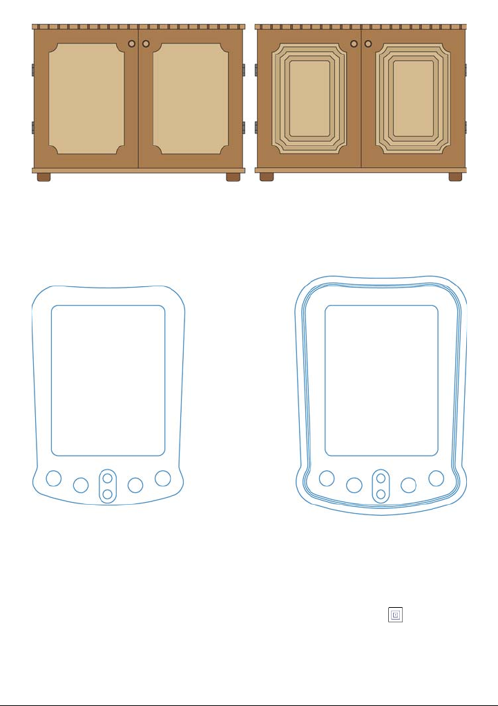
416 Corel DESIGNER X6 User Guide
A center contour has been applied to the cabinet on the right. The number of
contour lines, as well as the distance between lines, can be changed.
An outside contour has been applied to the above object. Note that an outside
contour projects from the outside edge of the object.
To contour an object
1Click the Interactive tools button, and click the Contour tool .
2Click an object or a set of grouped objects, and drag the start handle toward the
center to create an inside contour or away from the center to create an outside
contour.
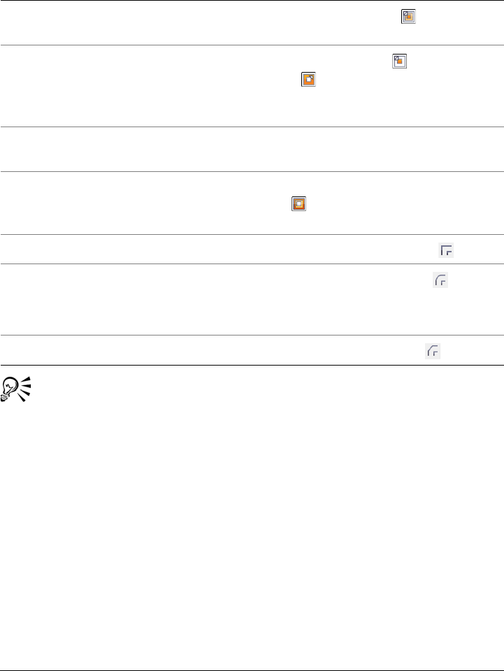
Adding 3D effects to objects 417
3Move the object slider to change the number of contour steps.
You can create contours by clicking Effects Contour and specifying the
settings you want in the Contour docker.
To copy or clone a contour
1Select the object to which you want to apply the contour effect.
2Click Effects, and click one of the following:
• Copy effect Contour from
• Clone effect Contour from
3Click the object whose contour effect you want to copy or clone.
You can also
Add contour lines to the center of the
selected object
Click the To c e n t e r button .
Specify the number of contour lines Click the Inside contour or Outside
contour button on the property bar, and
type a value in the Contour steps box on
the property bar.
Specify the distance between contour lines Type a value in the Contour offset box on
the property bar.
Accelerate contour line progression Click the Object and color acceleration
button on the property bar, and move the
object slider.
Use pointed contour corners Click the Mitered corners button .
Use rounded contour corners Click the Round corners button .
The effect of this control is more obvious
with outside contours.
Use beveled contour corners Click the Bevel corners button .
418 Corel DESIGNER X6 User Guide
You can also use the Attributes eyedropper tool to copy a contour. For
more information, see “To copy effects from one object to another” on
page 254.
To set the fill color for a contour object
1Click the Interactive tools button, and click the Contour tool .
2Select a contour object.
3Open the Fill color picker on the property bar, and click a color.
If you cannot apply the fill color, you need to make sure the Fill color option is
enabled on the status bar.
If the original object has a fountain fill, a second color picker appears.
You can accelerate the fill color progression by clicking the Object and color
acceleration button on the property bar.
You can change the contour center’s color by dragging a color from the color
palette to the end fill handle.
To specify an outline color for the contour object
1Click the Interactive tools button, and click the Contour tool .
2Select a contour object.
3Open the Outline color picker on the property bar, and click a color.
To set the fill progression
1Click the Interactive tools button, and click the Contour tool .
2Select a contour object.
3Click one of the following buttons on the property bar:
• Linear contour colors
• Clockwise contour colors
• Counterclockwise contour colors
To separate an object from its contour lines
1Using the Pick tool , select a contoured object.
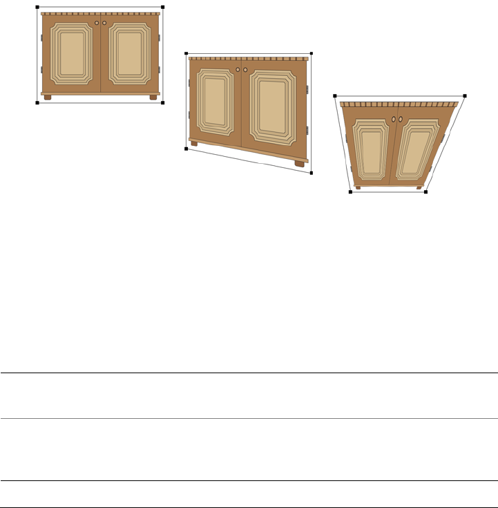
Adding 3D effects to objects 419
2Click Arrange Break contour group apart.
Applying perspective to objects
You can create a perspective effect by shortening one or two sides of an object. This
effect gives an object the appearance of receding in one or two directions, thereby
creating a one-point perspective or a two-point perspective.
Perspective effects can be added to objects or grouped objects. You can also add a
perspective effect to linked groups, such as contours, blends, and extrusions. You can’t
add perspective effects to paragraph text, bitmaps, or symbols.
The original graphic (left) with one-point (middle) and two-point (right)
perspectives applied to it.
After you apply a perspective effect, you can copy it to other objects in a drawing, adjust
it, or remove it from the object.
To apply a perspective
To
Apply a one-point perspective Click Effects Add perspective. Press
Ctrl, and drag a node.
Apply a two-point perspective Click Effects Add perspective. Drag the
nodes on the outside of the grid to apply the
effect you want.
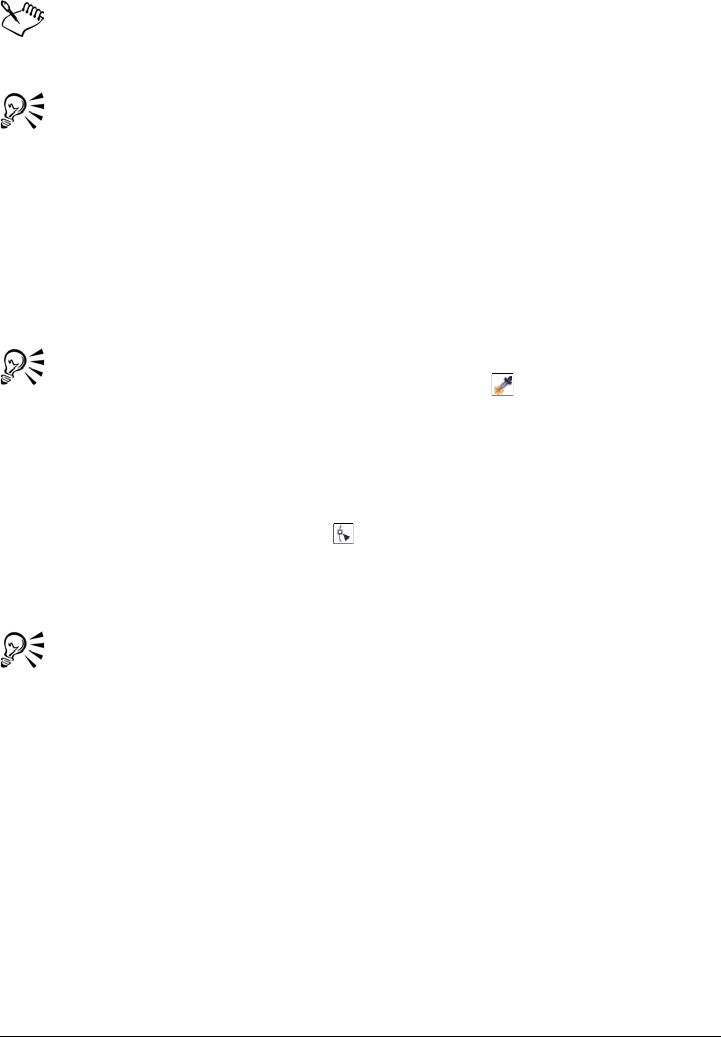
420 Corel DESIGNER X6 User Guide
Pressing Ctrl constrains the node’s movement to the horizontal or vertical axis
to create a one-point perspective effect.
You can move opposing nodes the same distance in opposite directions by
pressing Ctrl + Shift as you drag.
To copy an object’s perspective effect
1Select an object to which you want to apply a perspective effect.
2Click Effects Copy effect Perspective from.
3Select an object whose perspective effect you want to copy.
You can also use the Attributes eyedropper tool to copy a perspective
effect. For more information, see “To copy effects from one object to another”
on page 254.
To adjust the perspective
1In the toolbox, click the Shape tool
2Select an object that has a perspective effect.
3Drag a node to a new position.
You can also adjust the perspective by dragging one or both of the vanishing
points.
You can move opposing nodes the same distance in opposite directions by
pressing Ctrl + Shift while dragging the node.
To remove a perspective effect from an object
1Select an object that has a perspective effect.
2Click Effects Clear perspective.

Adding 3D effects to objects 421
Creating extrusions
You can make objects appear three-dimensional by creating extrusions. You can create
extrusions by projecting points from an object and joining them to create an illusion of
three dimensions. Corel DESIGNER also lets you apply a vector extrusion to an object
in a group.
After you create an extrusion, you can copy or clone its attributes to a selected object.
Cloning and copying transfer the extrusion attributes of an extruded object to another.
However, the cloned extrusion settings cannot be edited independently from the
master.
You can change an extruded form by rotating it, changing its direction, changing its
depth, and rounding its corners.
Corel DESIGNER also lets you remove a vector extrusion.
Bevels
Another way in which you can give an object a three-dimensional appearance is by
applying a beveled edge to an extrusion. A bevel creates the illusion that an object’s
extruded edges are cut on an angle. You can specify the angle and depth values of the
bevel to control the effect.
You can create a bevel effect without extruding an object. For more information, see
“Creating bevel effects” on page 426.
Extruded fills
You can apply fills to an entire extrusion or only to the extruded surfaces. You can cover
each surface individually with the fill, or you can drape the fill so that it blankets the
entire object with no breaks to the pattern or texture.
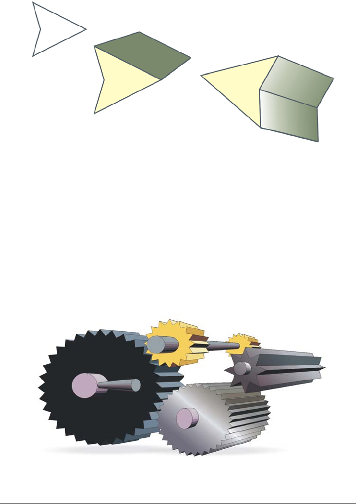
422 Corel DESIGNER X6 User Guide
Left to right: a simple shape, the shape with an extruded fill of solid color, the
shape with an extruded gradient fill and a rotation applied.
Lighting
You can enhance extrusions by applying light sources. You can add up to three light
sources to project toward the extruded object with varying intensity. When you no
longer need light sources, you can remove them.
Vanishing points
You can create a vector extrusion in which the lines of the extrusion converge at a
vanishing point. The vanishing point of a vector extrusion can be copied to another
object so that both objects appear to recede toward the same point.
Extrusions with the same vanishing point
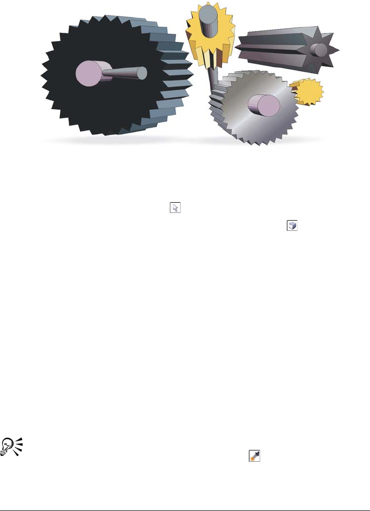
Adding 3D effects to objects 423
You can also give two extrusions different vanishing points.
Extrusions with different vanishing points
To create an extrusion
1Select an object using the Pick tool .
2Click the Interactive tools button, and click the Extrude tool .
3Choose a preset from the Presets list box on the property bar.
4Choose an extrusion type from the Extrusion type list box on the property bar.
5Select an object.
6Drag the object’s selection handles to set the direction and depth of the extrusion.
If you want to reset the extrusion, press Esc before releasing the mouse button.
To copy or clone an extrusion
1Select the object you want to extrude.
2Click Effects and click one of the following:
• Copy effect Extrude from
• Clone effect Extrude from
3Click an object whose extrusion properties you want to copy.
You can also use the Attributes eyedropper tool to copy an extrusion. For
more information, see “To copy effects from one object to another” on
page 254.
424 Corel DESIGNER X6 User Guide
To change the form of a vector extrusion
To remove a vector extrusion
1Select an extruded object.
2Click Effects Clear extrusion.
You can also remove a vector extrusion by clicking the Clear extrusion
button on the property bar.
To apply a fill to an extrusion
1Select an extruded object with the Extrude tool .
2Click the Extrusion color button on the property bar.
3Click one of the following buttons:
• Use object fill — applies the object’s fill to the extrusion
• Use solid color — applies a solid color to the extrusion
• Use color shading — applies a gradient fill to the extrusion
To Do the following
Rotate an extrusion Select an extruded object. Click the Extrude
rotation button on the property bar.
Drag the extrusion in the direction you
want.
Change the direction of an extrusion Using the Extrude tool , click an
extrusion. Click the vanishing point, and
drag in the direction you want.
Change the depth of an extrusion Using the Extrude tool , click an
extrusion. Drag the slider between the
interactive vector handles.
Round the corners of an extruded rectangle
or square
In the toolbox, click the Shape tool .
Drag a corner node along the outline of the
rectangle or square.
Adding 3D effects to objects 425
You can apply an unbroken pattern or texture fill to an object by enabling the
Drape fills check box before you click the Use object fill button.
To apply beveled edges to an extrusion
1Click the Interactive tools button, and click the Extrude tool .
2Select an extruded object.
3Click the Extrusion bevels button on the property bar.
4Enable the Use bevel check box.
5Type a value in the Bevel depth box.
6Type a value in the Bevel angle box.
You can also set the bevel depth and angle by using the Bevel interactive
display box below the Use bevel check box.
You can show only the bevel and hide the extrusion by enabling the Show
bevel only check box.
To add light to an extrusion
1Select an extruded object.
2Click the Extrusion lighting button on the property bar.
3Click any of the three Light buttons .
The lights appear as numbered circles in the preview window.
4Drag the numbered circles in the Light intensity preview window to position the
lights.
If you want to create more realistic shading, enable the Use full color range check
box.
You can also
Adjust the intensity of a light source Select a light in the Light intensity preview
window, and move the Intensity slider.
Remove a light source Click an active Light button.

426 Corel DESIGNER X6 User Guide
To change the vanishing point of an extrusion
Creating bevel effects
A bevel effect adds 3D depth to a graphic or text object by making its edges appear
sloped (cut at an angle). Bevel effects can contain both spot and process (CMYK) colors,
so they are ideal for printing.
You can remove a bevel effect at any time.
Bevel effects can be applied only to vector objects and text, not to bitmaps.
Bevel styles
You can choose from the following bevel styles:
•Soft edge — creates beveled surfaces that appear shaded in some areas
•Emboss — makes an object appear as a relief
To Do the following
Lock a vanishing point Double-click an extruded object. Choose VP
locked to object or VP locked to page
from the Vanishing point properties list
box on the property bar.
Copy a vanishing point Double-click an extruded object whose
vanishing point you want to change. From
the Vanishing point properties list box on
the property bar, choose Copy VP from.
Select the extruded object that has the
vanishing point you want to copy.
Set one vanishing point for two extrusions Double-click an extruded object. Choose
Shared vanishing point from the
Vanishing point properties list box on the
property bar. Select the extruded object that
has the vanishing point you want to share.

Adding 3D effects to objects 427
Left to right: Object without a bevel effect, with a Soft Edge bevel effect, and
with an Emboss bevel effect
Beveled surfaces
You can control the intensity of the bevel effect by specifying the width of the beveled
surface.
Light and color
An object with a bevel effect appears lit by white ambient (surrounding) light and a
spotlight. The ambient light is of low intensity and cannot be changed. The spotlight
is also white by default, but you can change its color, intensity, and location. Changing
the spotlight color affects the color of the beveled surfaces. Changing the spotlight’s
intensity lightens or darkens the beveled surfaces. Changing the location of the
spotlight determines which beveled surfaces appear lit.
You can change the location of the spotlight by specifying its direction and altitude.
Direction determines where the light source is located in the plane of the object (for
example, to the left or right of an object). Altitude determines how high the spotlight
is located in relation to the object’s plane. For example, you can place the spotlight flush
with the horizon (altitude of 0°) or directly above the object (altitude of 90°).
In addition, you can change the color of the beveled surfaces that are in shadow by
specifying a shadow color.
To create a Soft Edge bevel effect
1Select an object that is closed and has a fill applied to it.
428 Corel DESIGNER X6 User Guide
2Click Effects Bevel.
3In the Bevel docker, choose Soft edge from the Style list box.
4Enable one of the following Bevel offset options:
• To c e n t e r — lets you create beveled surfaces that meet in the middle of the
object
• Distance — lets you specify the width of the beveled surfaces. Type a value in
the Distance box.
The lowest altitude value (0°) places the spotlight on the plane of the object;
the highest altitude value (90°) places the spotlight directly above the object.
Using a given altitude value, you can change the spotlight’s location by
changing the direction value. For example, at an altitude of 45°, the following
direction values change the spotlight location as noted:
• 45° places the spotlight on the upper right.
• 135° places the spotlight on the upper left.
• 225° places the spotlight on the lower left.
• 315° places the spotlight on the lower right.
The effect of the shadow color is most apparent when the spotlight is located
close to the object’s plane (low altitude value).
You can also
Change the color of beveled surfaces in
shadow
Choose a color from the Shadow color
picker.
Beveled surfaces change to a shade of the
specified shadow color.
Choose a spotlight color Choose a color from the Light color picker.
Change the intensity of the spotlight Move the Intensity slider.
Specify the position of the spotlight Move either of the following sliders:
•Direction
•Altitude
Direction values range from 0° to 360°;
altitude values range from 0° to 90°.
Adding 3D effects to objects 429
To create an Emboss effect
1Select an object that is closed and has a fill applied to it.
2Click Effects Bevel.
3In the Bevel docker, choose Emboss from the Style list box.
4In the Distance box, type a low value.
5To change the intensity of the spotlight, move the Intensity slider.
6To specify the direction of the spotlight, move the Direction slider.
7Click Apply.
If you want to create a more pronounced bevel effect, type a higher value in the
Distance box, and reapply the effect.
The Emboss bevel effect is achieved by creating two duplicates of the object.
The duplicates are offset in opposite directions: one toward the light source and
the other away from the light source. The color of the duplicate placed toward
the spotlight is a blend of the spotlight and object colors and depends on the
light intensity. The color of the duplicate placed away from the spotlight is a
50 percent blend of the shadow and object colors.
The Altitude slider is disabled for the Emboss bevel style.
To remove a bevel effect
1Select an object with a bevel effect applied.
2Click Effects Clear effect.
Creating drop shadows
Drop shadows simulate light falling on an object from one of five particular
perspectives: flat, right, left, bottom, and top. You can add drop shadows to most
objects or groups of objects, including artistic text, paragraph text, and bitmaps.
You can also
Choose a shadow color Choose a color from the Shadow color
picker.
Choose a spotlight color Choose a color from the Light color picker.
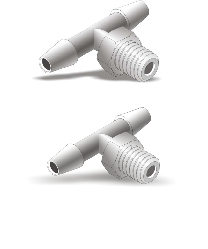
430 Corel DESIGNER X6 User Guide
Drop shadows created in Corel DESIGNER are ideal for printed outputs, but are not
appropriate for output to devices such as vinyl cutters and plotters. Cuttable shadows
are needed for such projects. To add a cuttable shadow to an object, you need to
duplicate the object, fill the duplicate with a dark color, and then place it behind the
original object. When you add a drop shadow, you can change its perspective, and you
can adjust attributes such as color, opacity, fade level, angle, and feathering.
A drop shadow applied to an object
The feathered effect softens the edges of a drop shadow.
After you create a drop shadow, you can copy it or clone it to a selected object. When
you copy a drop shadow, the original and copy have no connection and can be edited
independently. With cloning, the master object’s drop shadow attributes are
automatically applied to its clone.

Adding 3D effects to objects 431
By separating a drop shadow from its object, you gain more control over the drop
shadow itself. For example, you can edit the drop shadow as you would edit a
transparency. For information about editing a transparency, see “Applying
transparencies” on page 439.
As with transparencies, you can apply a merge mode to a drop shadow to control how
the color of the drop shadow blends with the color of the object underneath.
You can remove a drop shadow.
To add a drop shadow
1Click the Interactive tools button, and click the Drop shadow tool .
2Click an object.
3Drag from the center or side of the object until the drop shadow is the size you
want.
4Specify any attributes on the property bar.
Drop shadows cannot be added to linked groups, such as blended objects,
contoured objects, beveled objects, extruded objects, objects created with the
Linear pattern brush tool , or other drop shadows.
To add a cuttable shadow
1Select an object.
2Click Edit Duplicate.
3Click a dark color on the onscreen color palette.
4Click Arrange Order Behind, and click the original to position the duplicate
behind it.
5Adjust the position of the duplicate.
To copy or clone a drop shadow
1Select the object to which you want to copy or clone a drop shadow.
2Click Effects and click one of the following:
• Copy effect Drop shadow from
• Clone effect Drop shadow from
3Click the drop shadow of an object.
432 Corel DESIGNER X6 User Guide
You can also use the Attributes eyedropper tool to copy a drop shadow.
For more information, see “To copy effects from one object to another” on
page 254.
To separate a drop shadow from an object
1Select an object’s drop shadow.
2Click Arrange Break drop shadow group apart.
3Drag the shadow.
To apply a merge mode to a drop shadow
1Click the Interactive tools button, and click the Drop shadow tool .
2Select an object with a drop shadow, and choose a merge mode from the
Transparency operation list box on the property bar.
The default merge mode Multiply produces natural-looking drop shadows.
To remove a drop shadow
1Select an object’s drop shadow.
2Click Effects Clear drop shadow.
You can also remove a drop shadow from an object by clicking the Clear drop
shadow button on the property bar.
Blending objects
Corel DESIGNER lets you create blends, such as straight-line blends, blends along a
path, and compound blends. Blends are often used for creating realistic shadows and
highlights in objects.
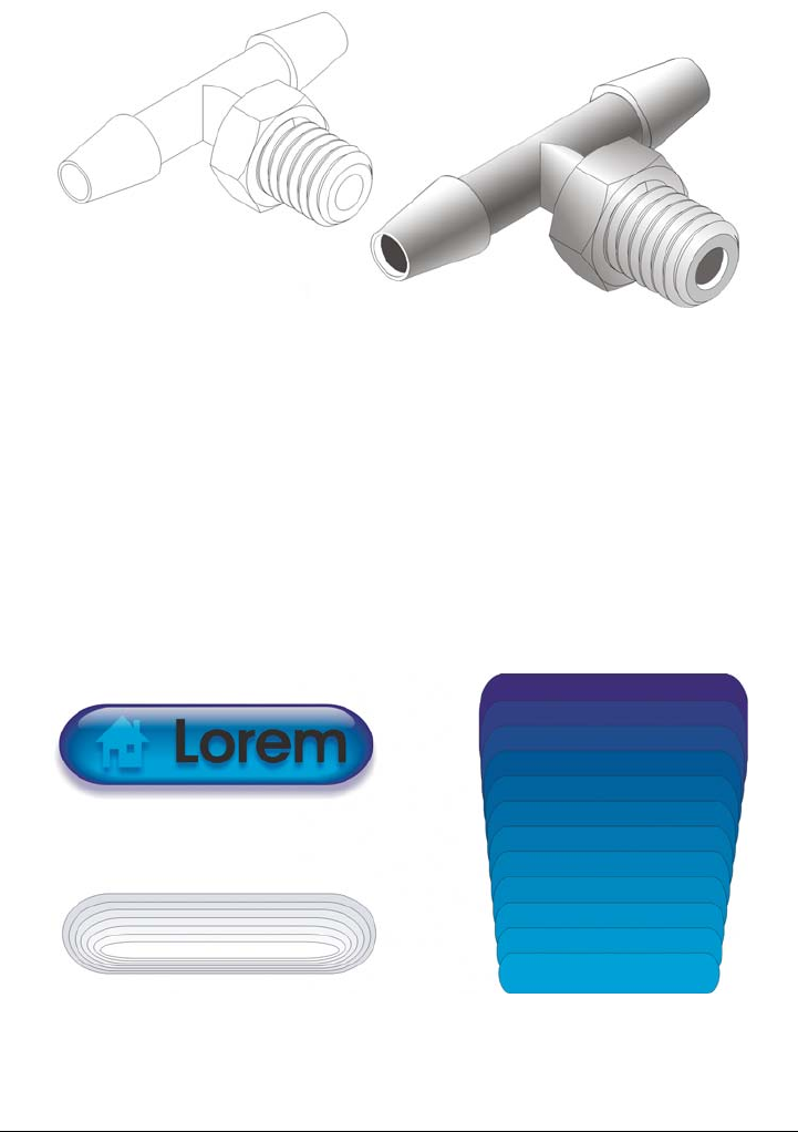
Adding 3D effects to objects 433
The highlights and shadows in the object on the right were created by using
blends.
A straight-line blend shows a progression in shape and size from one object to another.
The outline and fill colors of the intermediate objects progress along a straight-line path
across the color spectrum. The outlines of intermediate objects show a gradual
progression in thickness and shape.
After you create a blend, you can copy or clone its settings to other objects. When you
copy a blend, the object takes on all the blend-related settings, except for the outline
and fill attributes. When you clone a blend, changes you make to the original blend
(also called the master) are applied to the clone.
Straight-line blends can be used to create graphics with a glass-like
appearance. The rollover button (left) contains a blend of tightly overlapped
blended objects.

434 Corel DESIGNER X6 User Guide
You can fit objects along part or all of a path’s shape, and you can add one or more
objects to a blend to create a compound blend.
The straight-line blend (top) is fitted to a curved path (bottom).
You can change the appearance of a blend by adjusting the number and spacing of its
intermediate objects, the blend’s color progression, the nodes the blends map to, the
blend’s path, and the start and end objects. You can fuse the components of a split or
compound blend to create a single object.
You can also split and remove a blend.
By mapping nodes, you can control the appearance of a blend.
Adding 3D effects to objects 435
To blend objects
To copy or clone a blend
1Select the two objects that you want to blend.
2Click Effects, and click one of the following:
• Copy effect Blend from
• Clone effect Blend from
3Select the blend whose attributes you want to copy or clone.
You can’t copy or clone a compound blend.
To Do the following
Blend along a straight line Click the Interactive tools button, and click
the Blend tool . Select the first object,
and drag over the second object. If you want
to reset the blend, press Esc as you drag.
Blend an object along a freehand path Click the Interactive tools button, and click
the Blend tool . Select the first object.
Hold down Alt, and drag to draw a line to
the second object.
Fit a blend to a path Click the Interactive tools button, and click
the Blend tool . Click the blend. Click
the Path properties button on the
property bar. Click New path. Using the
curved arrow, click the path to which you
want to fit the blend.
Stretch the blend over an entire path Select a blend that is already fitted on a path.
Click the More blend options button on
the property bar, and enable the Blend
along full path check box.
Create a compound blend Using the Blend tool, drag from an object to
the start or end object of another blend.
436 Corel DESIGNER X6 User Guide
You can also use the Attributes eyedropper tool to copy a blend. For more
information, see “To copy object properties from one object to another” on
page 253.
To set the number of intermediate objects in a blend
1Select a blend.
2Type a value in the Blend objects box on the property bar.
3Press Enter.
You can set object and color acceleration rates by clicking the Object and
color acceleration button on the property bar and moving the
corresponding slider.
To set the distance between objects in a blend that is fit to a path
1Select a blend that is fit to a path.
2Click the Blend spacing button on the property bar.
3Type a value in the Blend objects box on the property bar.
4Press Enter.
If you have used the Blend along full path command, the Blend spacing
button is unavailable.
You can set object and color acceleration rates by clicking the Object and
color acceleration button on the property bar and moving the
corresponding slider.
To set the color progression in a blend
1Select a blend.
2On the property bar, click one of the following:
• Direct blend
• Clockwise blend
• Counterclockwise blend
Adding 3D effects to objects 437
You can’t create color progressions by using blended objects filled with
bitmaps, texture, pattern, or PostScript fills.
You can set how fast the object’s colors transform from the first to the last
object by clicking the Object and color acceleration button on the
property bar and moving the corresponding sliders.
To map the nodes of a blend
1Select a blend.
2Click the More blend options button on the property bar, and click Map
nodes.
3Click a node on the start object and on the end object.
To work with the start or end objects in a blend
You can reverse the direction of the blend by clicking Arrange Order
Reverse order.
To Do the following
Select the start or end object Select a blend, click the Starting and
ending objects button on the property
bar, and click Show start or Show end.
Change the start or end object of a blend Select a blend, click the Starting and
ending objects button on the property bar,
and click New start or New end. Click an
object outside the blend that you want to use
as the start or end of the blend.
Fuse the start or end object in a split or
compound blend
Hold down Ctrl, click a middle object in a
blend, and then click a start or end object.
Click the More blend options button on
the property bar. If you have selected the
start object, click the Fuse start button .
If you have selected the end object, click the
Fuse end button .
438 Corel DESIGNER X6 User Guide
To change the blend path
1Select a blend.
2Click the Path properties button on the property bar, and click New path.
3Click the path you want to use for the blend.
To select the blend path, click the Path properties button , and click Show
path.
To split a blend
1Select a blend.
2Click the More blend options button on the property bar.
3Click the Split button .
4Click the intermediate object at the point at where you want to split the blend.
You can’t split a blend at the intermediate object that is immediately adjacent
to the start or end object.
To remove a blend
1Select a blend.
2Click Effects Clear blend.
You can also remove a selected blend by clicking the Clear blend button
on the property bar.
You can also
Detach a blend from a path Click the Path properties button on the
property bar, and click Detach from path.
Change the path of a selected freehand blend Click the blend path with the Shape tool
, and drag a path’s node.

Changing the transparency of objects 439
Changing the transparency of
objects
You can apply a transparency to an object so that all objects behind it show through.
The Corel DESIGNER application also lets you specify how the color of the
transparent object combines with the color of the object beneath it.
This section contains the following topics:
• Applying transparencies
•Applying merge modes
Applying transparencies
When you apply a transparency to an object, you make the objects beneath it partially
visible. You can apply transparencies using the same kind of fills you apply to objects;
that is, uniform, fountain, texture, and pattern. For more information about these fills,
see “Filling objects” on page 361.
By default, the program applies all transparencies to the object’s fill and outline;
however, you can specify whether you want the transparency to apply only to the
object’s outline or fill.
You can also copy a transparency from one object to another.
When you position a transparency over an object, you can freeze it, making the view of
the object move with the transparency.
To apply a uniform transparency
1Select an object.
2Click the Interactive tools button, and click the Transparency tool .
3On the property bar, choose Uniform from the Transparency type list box.
4Type a value in the Starting transparency box on the property bar, and press
Enter.
440 Corel DESIGNER X6 User Guide
You can click a color on the color palette to apply a color to the transparency.
To apply a fountain transparency
1Select an object.
2Click the Interactive tools button, and click the Transparency tool .
3On the property bar, choose one of the following fountain transparencies from the
Transparency type list box:
• Linear
• Radial
• Conical
• Square
4Reposition the interactive vector handles that appear, or point to where you want
the transparency to start on the object, and drag to where you want the
transparency to end.
If you want to reset the transparency, press Esc before releasing the mouse button.
5Type a value in the Transparency midpoint box on the property bar, and press
Enter.
You can create a custom fountain transparency by dragging colors, whose
shades convert to grayscale, from the color palette onto the object’s interactive
vector handles .
To apply a textured transparency
1Select an object.
2In the toolbox, click the Interactive tools button, and click the Tr a n s p a r en c y tool
.
3Choose Texture from the Tr a n s p a r e n c y t y p e list box on the property bar.
4Choose a sample from the Texture library list box on the property bar.
5Open the Transparency pattern picker on the property bar, and click a texture.
6On the property bar, type values in the following boxes:
• Starting transparency — lets you change the opacity of the starting color
• Ending transparency — lets you change the opacity of the ending color

Changing the transparency of objects 441
To apply a pattern transparency
1Select an object.
2In the toolbox, click the Interactive tools button, and click the Tr a n s p a r e n c y tool
.
3From the Tr a n s p a r e n c y t y p e list box on the property bar, choose one of the
following:
• Two-color pattern — a simple picture composed of “on” and “off ” pixels. The
only shades included in the picture are the two that you assign.
• Full-color pattern — a picture composed of lines and fills, instead of dots of
color like bitmaps. These vector graphics are smoother and more complex than
bitmap images and are easier to manipulate.
• Bitmap pattern — a color picture composed of patterns of light and dark or
differently colored pixels in a rectangular array.
4Open the Transparency pattern picker on the property bar, and click a pattern.
5On the property bar, type values in the following boxes:
• Starting transparency
• Ending transparency
To specify the extent of a transparency
1In the toolbox, click the Interactive tools button, and click the Tr a n s p a r e n c y tool
.
2Select an object to which a transparency has been applied.
3From the Tr a n s p a r e n c y t a r g e t list box on the property bar, choose one of the
following:
• Fill
• Outline
• All
To copy a transparency to another object
1Select the object to which you want to copy the transparency.
2Click Effects Copy effect Lens from.
3Click the object from which you want to copy the transparency.

442 Corel DESIGNER X6 User Guide
To freeze the contents of a transparency
1In the toolbox, click the Interactive tools button, and click the Tr a n s p a r en c y tool
.
2Select an object to which a transparency has been applied.
3Click the Freeze transparency button on the property bar.
The view of the object beneath the transparency moves with it; however, the
actual object remains unchanged.
Applying merge modes
You can apply a merge mode to a transparency to specify how the color of a transparency
is combined with the color of the object behind it. The following merge modes available
for transparencies can also be applied to drop shadows.
Merge mode Description
Normal Applies the transparency color on top of the
base color
Add Adds the values of the transparency color
and the base color
Subtract Adds the values of the transparency color
and the base color together, and then
subtracts 255
Difference Subtracts the transparency color from the
base color and multiplies by 255. If the
transparency color value is 0, the result will
always be 255.
Multiply Multiplies the base color by the transparency
color, and then divides by 255. This has a
darkening effect, unless you are applying
color to white. Multiplying black with any
color results in black. Multiplying white
with any color leaves the color unchanged.

Changing the transparency of objects 443
Divide Divides the base color by the transparency
color, or conversely, divides the transparency
color by the base color, depending on which
color has the higher value
If lighter Replaces any base color pixels that are a
darker color with the transparency color.
Base color pixels that are lighter than the
transparency color are not affected.
If darker Replaces any base color pixels that are a
lighter color with the transparency color.
Base color pixels that are darker than the
transparency color are not affected.
Texturize Converts the transparency color to grayscale,
and then multiplies the grayscale value by
the base color
Color Uses the hue and saturation values of the
source color and the lightness value of the
base color to create a result. This merge
mode is the opposite of the Lightness merge
mode.
Hue Uses the hue of the transparency color, as
well as the saturation and lightness of the
base color. If you are adding color to a
grayscale image, there will be no change
because the colors are desaturated.
Saturation Uses the lightness and hue of the base color
and the saturation of the transparency color
Lightness Uses the hue and saturation of the base color
and the lightness of the transparency color
Invert Uses the transparency color’s
complementary color. If a transparency color
value is 127, there will be no change because
the color value falls in the center of the color
wheel.
Merge mode Description

444 Corel DESIGNER X6 User Guide
Logical AND Converts the transparency and base colors to
binary values, and then applies the Boolean
algebraic formula AND to these values
Logical OR Converts the transparency and base colors to
binary values, and then applies the Boolean
algebraic formula OR to these values
Logical XOR Converts the transparency and base colors to
binary values, and then applies the Boolean
algebraic formula XOR to these values
Behind Applies the source color to those areas of the
image that are transparent. The effect is
similar to looking through the clear, silver-
free areas on a 35-mm negative.
Screen Inverts the source and base color values,
multiplies them, and then inverts the result.
The result color is always lighter than the
base color.
Overlay Multiplies or screens the source color
according to the value of the base color
Soft light Applies a soft, diffused light to the base color
Hard light Applies a hard, direct spotlight to the base
color
Color dodge Simulates the photographic technique called
dodging, which lightens image areas by
decreasing the exposure
Color burn Simulates the photographic technique called
burning, which darkens image areas by
increasing the exposure
Exclusion Excludes the transparency color from the
base color. This mode is similar to the
Difference mode.
Merge mode Description

Changing the transparency of objects 445
To apply a merge mode to a transparency
1Click the Interactive tools button, and click the Transparency tool .
2Select an object with a transparency.
3Choose a merge mode from the Transparency operation list box on the property
bar.
Red Applies the transparency color to the red
channel of RGB objects
Green Applies the transparency color to the green
channel of RGB objects
Blue Applies the transparency color to the blue
channel of RGB objects
Merge mode Description

Using lenses with objects 447
Using lenses with objects
Lenses contain creative effects that let you change the appearance of an object without
actually changing the object.
This section contains the following topics:
• Applying lenses
• Editing lenses
Applying lenses
Lenses change how the object area beneath the lens appears, not the actual properties
and attributes of the objects. You can apply lenses to any vector object, such as a
rectangle, ellipse, closed path, or polygon. You can also change the appearance of artistic
text and bitmaps. When you apply a lens over a vector object, the lens itself becomes a
vector image. Likewise, if the lens is placed over a bitmap, the lens also becomes a
bitmap.
After you apply a lens, you can copy it and use it with another object.
The following are the types of lenses that you can apply to objects.
Lens Description
Brighten Lets you brighten and darken object areas
and set the rate of the brightness and
darkness
Color add Lets you simulate an additive light model.
The colors of the objects beneath the lens are
added to the color of the lens as if you were
mixing colors of light. You can choose the
color and the amount of color you want to
add.

448 Corel DESIGNER X6 User Guide
Color limit Lets you view an object area with only black
and the lens color showing through. For
example, if you place a green color limit lens
over a bitmap, all colors except green and
black are filtered out in the lens area.
Custom color map Lets you change all the colors of the object
area beneath the lens to a color ranging
between two colors you specify. You can
choose the range’s start and end colors and
the progression between the two colors. The
progression can follow a direct, forward, or
reverse route through the color spectrum.
Fish eye Lets you distort, magnify, or shrink the
objects beneath the lens, according to the
percentage value you specify
Heat map Lets you create the effect of an infrared
image by mimicking the heat levels of colors
in object areas beneath the lens
Invert Lets you change the colors beneath the lens
to their complementary CMYK colors.
Complementary colors are colors that are
opposite each other on the color wheel.
Magnify Lets you magnify an area on an object by an
amount that you specify. The magnify lens
overrides the original object’s fill, making
the object look transparent.
Tinted grayscale Lets you change the colors of object areas
beneath the lens to their grayscale
equivalents. Tinted grayscale lenses are
particularly effective for creating sepia-tone
effects.
Transparency Lets you make an object look like a piece of
tinted film or colored glass
Lens Description

Using lenses with objects 449
To apply a lens
1Select an object.
2Click Effects Lens.
3Choose a lens type from the list box in the Lens docker.
4Specify the settings you want.
You cannot apply the lens effect directly to linked groups such as contoured
objects, beveled objects, extruded objects, paragraph text or objects created
with Linear pattern tools.
You can preview the different types of lenses in real time without auto-
applying them to a drawing by clicking the Lock button and then choosing a
lens and settings to preview. When you find the lens you want to use, click
Apply, or click the Lock button again to resume auto-applying the lenses
while previewing them.
To copy a lens
1Select the object to which you want to copy the lens.
2Click Effects Copy effect Lens from.
3Click the object from which you want to copy the lens.
Editing lenses
You can edit a lens to change how it affects the area beneath it. For example, you can
change the viewpoint of a lens, indicated by an X in the drawing window, to display any
Wireframe Lets you display the object area beneath the
lens with the outline or fill color of your
choice. For example, if you set red for the
outline and blue for the fill, all areas beneath
the lens appear to have red outlines and blue
fills.
Lens Description

450 Corel DESIGNER X6 User Guide
part of a drawing. The viewpoint represents the center point of what is being viewed
through the lens. You can position the lens anywhere in the drawing window, but it
always shows the area around its viewpoint marker. For example, you can use the
viewpoint marker on the Magnify lens to enlarge part of a map.
You can also display a lens only where it overlaps other objects or the background. As a
result, the lens effect is not seen where the lens covers blank space (white space) in the
drawing window.
Freezing the current view of a lens lets you move the lens without changing what’s
displayed through it. In addition, changes you make to the areas beneath the lens have
no effect on the view.
To edit a lens
1Select an object.
2Click Effects Lens.
3Enable the Viewpoint check box on the Lens docker.
If you want to display a lens only where it covers other objects, enable the Remove
face check box.
4Click Edit to display the viewpoint marker.
5Drag the viewpoint marker in the drawing window to a new location.
6Click End.
If you want to freeze the current view of a lens, enable the Frozen check box.
7Click Apply.
The Remove face check box is not available for the Fish Eye and Magnify
lenses.

Text 451
Text
Adding and manipulating text . . . . . . . . . . . . . . . . . . . . . . . . . . . . . . . .453
Formatting text . . . . . . . . . . . . . . . . . . . . . . . . . . . . . . . . . . . . . . . . . . . .483
Working with text in different languages . . . . . . . . . . . . . . . . . . . . . . .521
Managing fonts. . . . . . . . . . . . . . . . . . . . . . . . . . . . . . . . . . . . . . . . . . . .529
Using writing tools . . . . . . . . . . . . . . . . . . . . . . . . . . . . . . . . . . . . . . . . .533

Adding and manipulating text 453
Adding and manipulating text
Corel DESIGNER provides multiple ways to add and manipulate text (also known as
‘type’). You can create two types of text objects: artistic text and paragraph text.
Artistic text is useful for adding a single word or a short line of text. Paragraph text is
suitable for creating text-intensive documents, such as newsletters or brochures.
You can change the position and appearance of text. For example, you can fit text to a
path, wrap text around objects, or rotate text. You can also format the appearance of
characters and paragraphs. For more information, see “Formatting text” on page 483.
This section contains the following topics:
• Importing and pasting text
• Adding artistic text
•Adding paragraph text
•Adding columns to text frames
• Combining and linking paragraph text frames
• Aligning text by using the baseline grid
• Selecting text
• Finding, editing, and converting text
• Shifting, rotating, mirroring, and flipping text
•Moving text
•Wrapping text
• Fitting text to a path
• Embedding graphics and adding special characters
• Working with legacy text
454 Corel DESIGNER X6 User Guide
Importing and pasting text
You can import text in a new or existing document. This allows you to author text in a
word processor and then add it to a Corel DESIGNER document. Corel DESIGNER
supports the following text file formats:
•ANSI Text (TXT)
• Microsoft Word Document (DOC) files
• Microsoft Word Open XML Document (DOCX) files
• WordPerfect file (WPD)
•Rich Text Format (RTF) files
When importing or pasting text, you can choose to keep or discard fonts and
formatting. Maintaining fonts ensures that imported or pasted text retains its original
font. Maintaining formatting preserves information such as bullets and columns. If you
choose to discard fonts and formatting, the properties of the selected text are applied to
the imported or pasted text. If no text is selected, the default font and formatting
properties are applied to the imported or pasted text. For more information about
importing files, see “Importing files” on page 741. For more information about pasting,
see “To paste an object into a drawing” on page 250.
The text import cursor lets you place text on the drawing page.
You can import text in a selected text frame, or, if you did not select a text frame, the
imported text is automatically inserted in a new text frame in the document window.
By default, the size of text frames remains static, regardless of how much text you add
to them. Any text that does not fit the frame is hidden and the frame appears red until
you enlarge it or link it to another text frame. You can adjust the text size so that the
text fits perfectly in the frame. For more information, see “Combining and linking
paragraph text frames” on page 463.

Adding and manipulating text 455
To import text in a document
1Using the Te x t tool , position the cursor in the text frame where you want to
import the text.
If you do not have a text frame in the document, skip step 1 and proceed to step 2.
2Click File Import.
3Choose the drive and folder where the file is stored.
4Click the filename.
5Click Import.
6In the Importing/Pasting text dialog box, choose one of the following options:
• Maintain fonts and formatting
• Maintain formatting only
• Discard fonts and formatting
If you want to apply CMYK black to the imported black text, enable the Force
CMYK black check box. This check box is available when you choose an option
that maintains text formatting.
7Do one of the following:
• Position the import cursor in the drawing page, and click.
• Click and drag on the drawing page to define the size of the text frame.
• Press the Spacebar to place the imported text in the default location.
For more information about importing a specific file format, see “Supported file
formats” on page 783.
To paste text in a document
1Copy or cut text.
2Click Edit Paste.
3In the Importing/Pasting text dialog box, enable one of the following options:
• Maintain fonts and formatting
• Maintain formatting only
• Discard fonts and formatting
If you want to apply CMYK black to the imported black text, enable the Force
CMYK black check box. This check box is available when you choose an option
that maintains text formatting.
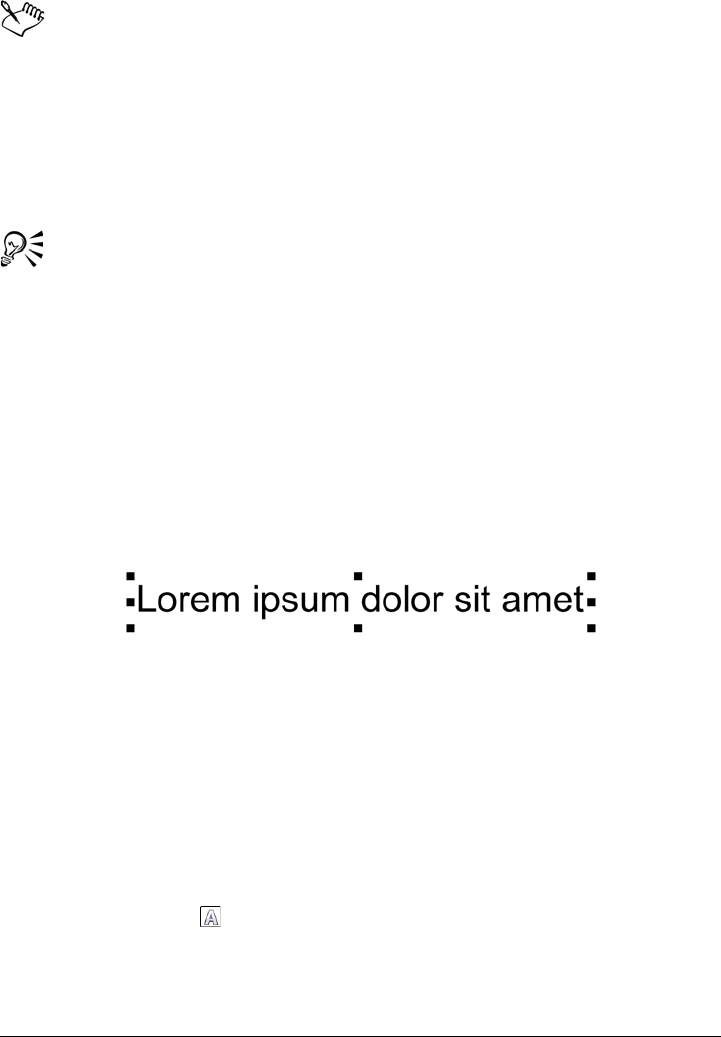
456 Corel DESIGNER X6 User Guide
If you choose to maintain fonts, but the text that you import requires a font
that is not installed on your computer, the PANOSE font matching system
substitutes the font for you. For more information, see “Substituting fonts” on
page 529.
You can also set hyphenation options for imported text. For more information
about hyphenation options, see “To create a custom definition for optional
hyphenation” on page 516.
If you want to use the same formatting options whenever you import or paste
text, enable the Don’t show this warning again check box. To reactivate the
warning, click To o l s Options, click Wa r ni n gs in the Work sp ac e list of
categories, and enable the Pasting and importing text check box.
Adding artistic text
Artistic text is useful for adding single words or short lines of text, such as headlines, to
a document. You can then apply a wide range of effects to the artistic text, such as drop
shadows or a contour.
Artistic text appears in a bounding box in the document window
You can add artistic text along an open or closed path or fit existing artistic to a path.
For more information, see “Fitting text to a path” on page 476.
In addition, you can assign hyperlinks to text. For more information, see “To assign a
hyperlink to text” on page 302.
To add artistic text
•Using the Te x t tool , click anywhere on the drawing page, and type.
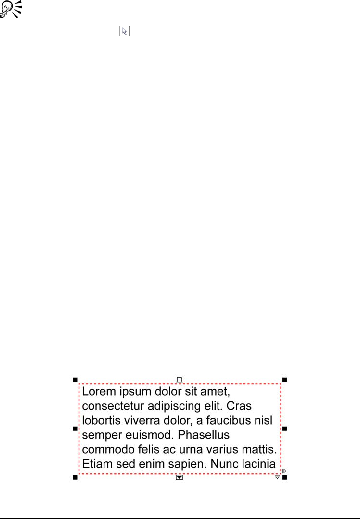
Adding and manipulating text 457
You can convert artistic text to paragraph text by selecting the artistic text
using the Pick tool and then clicking Te x t Convert to paragraph text.
Adding paragraph text
You add paragraph text in a document by using text frames. Paragraph text, also known
as “block text,” is generally reserved for larger bodies of text that have greater
formatting requirements. For example, you can use paragraph text when creating
brochures, newsletters, catalogues, or other text-intensive documents.
You can insert a text frame directly in the drawing window. You can also place text
inside a graphic object, which increases the number of different shapes that you can use
as text frames. You can create a text frame from a closed object and then type text inside
the frame. You can separate the frame from the object at any time, so that you can
modify them independently. You can convert a text frame back to an object.
If you want to see the layout of your document before you add the final content, you
can fill the text frames with temporary placeholder text. You can also use custom
placeholder text.
By default, text frames have a fixed size, regardless of how much text you add to them.
You can increase or decrease the frame size, so that the text fits in the frame. If you add
more text than a frame allows, the text continues past the lower-right border of the text
frame, but remains hidden. The color of the frame turns red to alert you that there's
additional text. You can fix the overflow manually by increasing the frame size,
adjusting the text size, adjusting the column width, or linking the frame to another text
frame. For more information, see “Combining and linking paragraph text frames” on
page 463.
The text frame turns red to indicate that there is additional text.
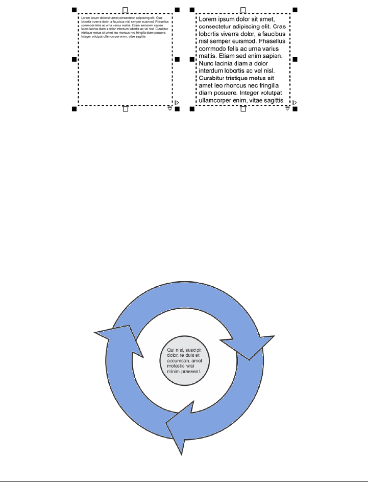
458 Corel DESIGNER X6 User Guide
You can also choose to automatically adjust the point size of text so that it fits neatly
inside a frame. If the text overflows, Corel DESIGNER automatically decreases the
point size; if you have little text, the application expands it to fill the frame.
The point size of the text in the frame (left) was automatically adjusted so that
it fits neatly inside the frame (right).
You can also change the formatting of selected paragraph text frames and any frames to
which they are linked. For information, see “To specify formatting preferences for text
frames” on page 466. You can also align text inside a text frame by using the baseline
grid. For more information, see “Aligning text by using the baseline grid” on page 467.
In addition, you can assign hyperlinks to paragraph text. For more information, see “To
assign a hyperlink to text” on page 302. You can also change the text orientation for
Asian text. For more information, see “To choose a text orientation for Asian text” on
page 522.
Paragraph text placed inside an object.
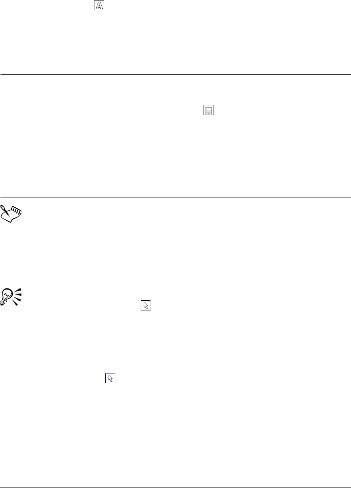
Adding and manipulating text 459
To add paragraph text
1Click the Te x t tool .
2Drag in the drawing window to size the paragraph text frame.
3Type in the text frame.
A red text frame indicates text overflow. You can fix the overflow manually by
increasing the frame size, adjusting the text size, or linking the frame to
another text frame. For more information, see “Combining and linking
paragraph text frames” on page 463. You can also fix the overflow
automatically by clicking Te x t Paragraph text frame Fit text to frame.
You can use the Pick tool to adjust the size of a paragraph text frame. Click
the text frame, and drag any selection handle.
To create a frame from an object
1Do one of the following:
• Using the Pick tool , click the object in which you want to insert a text frame.
• Using a shape tool, draw a closed shape.
2Select the object, and click Te x t Paragraph text frame Create empty text
frame.
You can also
Set text frame column width to adjust
automatically to fit the text
Click Window Property manager. In the
Property manager docker, click the Frame
button to display the frame-related
options. In the Frame area, click the
Columns buttons. In the Column settings
dialog box, enable the Automatically adjust
frame width option.
Apply a background color to a text frame Open the Background color picker, and
click a color.
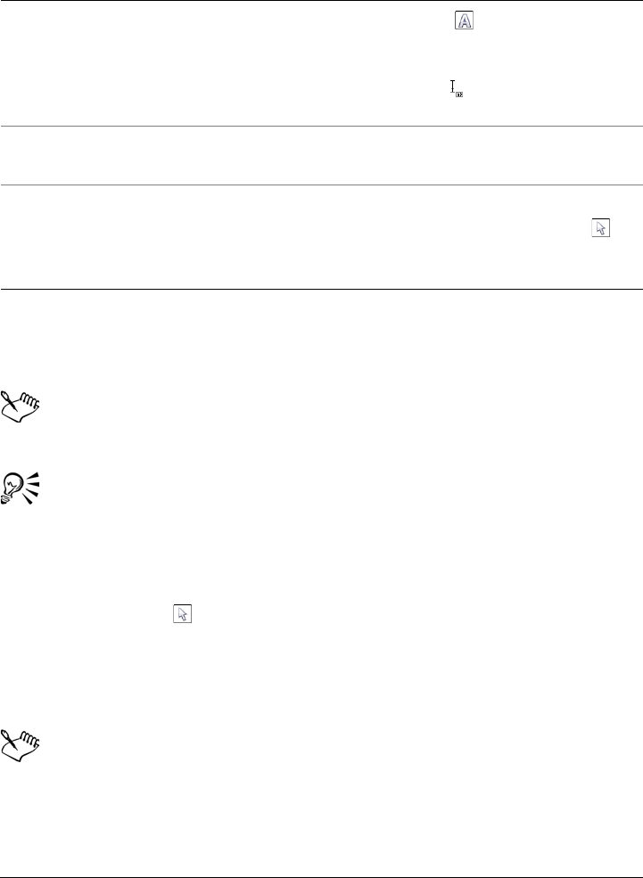
460 Corel DESIGNER X6 User Guide
To convert a text frame back to an object
• Right-click the text frame, choose Frame type, and click None.
If the frame contains content, the content is deleted when the frame reverts to
a regular object.
You can also click the No frame button on the Layout toolbar. To open the
Layout toolbar, click View To o l b a r s Layout or Layout Layout toolbar.
To separate a text frame from an object
1Click the Pick tool .
2Select the object that includes the text frame.
3Click Arrange Break paragraph text inside a path apart.
The text frame and the object can now be moved or edited separately.
When you separate a text frame from some objects, such as ellipses or stars, the
text does not retain the shape of the object. Alternatively, the text is contained
in a standard rectangular text frame.
You can also
Create a text frame from an object by using
the Te x t tool
Click the Te x t tool . Move the pointer
over the outline of the object, and click the
object when the pointer changes to an Insert
in object pointer . Type inside the text
frame.
Create a text frame from an object from the
right-click menu
Right-click the object, and click Frame type
Create empty text frame.
Create a text frame from an object by using
the Layout toolbar
Click View Toolbars Layout or Layout
Layout toolbar. Using the Pick tool ,
click the object in which you want to insert a
text frame. Click the Te x t f r a m e button.

Adding and manipulating text 461
To insert placeholder text
1Select an empty text frame.
2Click Te x t Paragraph text frame Insert placeholder text.
You can customize the placeholder text by creating text in a word processor or
text application and saving the document as placeholder.rtf. You then need to
store the file in the following Users folder: My Documents\Corel\Corel
Content. The next time that you launch the application, the customized
placeholder text is inserted in the text frame. However, if you save the file using
an incorrect file name or in the wrong folder, the default Lorem ipsum
placeholder text is inserted in the text frame.
You can insert placeholder text in multiple frames by clicking Pick tool ,
selecting the text frames while holding down Shift, and then clicking Te x t
Paragraph text frame Insert placeholder text.
You can also select the empty text frame, right-click, and choose Insert
placeholder text.
You can undo inserting placeholder text by clicking Edit Undo insert
placeholder text.
To adjust text to fill the text frame
1Select a text frame.
2Click Te x t Paragraph text frame Fit text to frame.
If you choose to fit text to a frame that is linked to other frames, the application
adjusts the size of text in all linked text frames. For more information about
linking text frames, see “Combining and linking paragraph text frames” on
page 463.
Adding columns to text frames
You can lay out text in columns. You can create columns of equal or varying widths and
gutters. You can also apply right-to-left text flow to the columns for bidirectional (bidi)
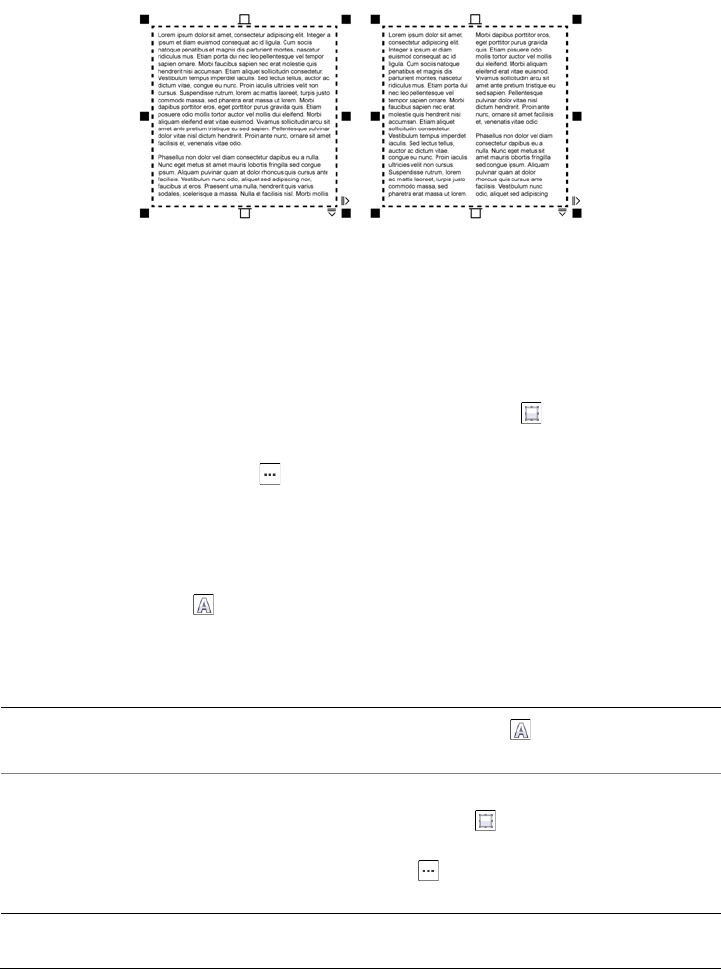
462 Corel DESIGNER X6 User Guide
text, such as Arabic and Hebrew (Note that this option is available only for certain
languages).
The text in the frame (left) was laid out in two columns (right).
To add columns to a text frame
1Select a paragraph text frame.
2Click Window Property manager.
3In the Property manager docker, click the Frame button to display the frame-
related options.
4Click the Columns button .
5In the Column settings dialog box, type a value in the Number of columns box.
To resize text frame columns
1Click the Te x t tool and select a text frame with columns.
2Perform a task from the following table.
To Do the following
Manually adjust column and gutter width Click the Te x t tool . Drag a column side
selection handle.
Set a specific column and gutter width In the Object properties docker, click the
Frame button to display the frame-
related options. Click the Columns
button , and type values in the Width or
Gutter boxes.

Adding and manipulating text 463
To change the flow of bidirectional text in columns
1Select a paragraph text frame.
2Click Window Property manager.
3In the Property manager docker, click the Frame button to display the frame-
related options.
4Enable the Right-to-left columns check box.
The Right-to-left columns option is available only for bidirectional
languages, such as Hebrew and Arabic. The proper keyboard must also be
installed.
Combining and linking paragraph text frames
You can combine text frames. You can also break text frames apart into subcomponents
— columns, paragraphs, bullets, lines, words, and characters. Every time you break
apart a text frame, the subcomponents are placed into separate text frames.
Linking text frames directs the overflow text of one text frame to another. If you resize
a linked frame, or change the size of the text, the amount of text in the next frame is
automatically adjusted. You can link text frames before or after you type text.
You cannot link artistic text. However, you can link a paragraph frame to an open or
closed object. When you link a frame to an open object, such as a line, the text flows
along the path of the line. Linking a text frame to a closed object, such as a rectangle,
inserts a text frame and directs the flow of text inside the object. If text exceeds the open
or closed path, you can link the text to another frame or object. You can also link to
existing frames and objects across pages or create a linked frame in the same location on
another page.
Automatically create columns of equal width In the Object properties docker, click the
Frame button to display the frame-
related options. Click the Columns
button , and enable the Equal column
width check box.
To Do the following
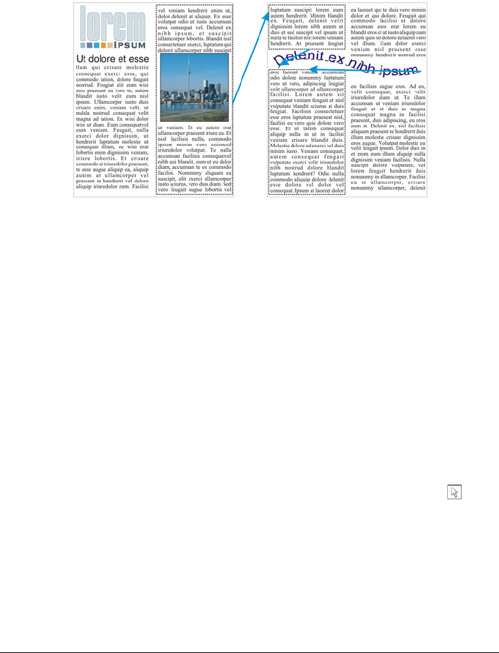
464 Corel DESIGNER X6 User Guide
After linking text frames, you can redirect the flow from one object or text frame to
another. When you select the text frame or object, a blue arrow indicates the direction
of the text flow. You can hide or display these arrows.
You can make text flow between text frames and objects by linking the text.
You can remove links between multiple frames, and between frames and objects. When
you have only two linked frames and you remove the link, the overflow text is merged
back into the first frame. Removing the link from a frame that is part of a series of linked
frames redirects the text flow into the next frame or object.
By default, paragraph formatting, such as columns, drop caps, and bullets, is applied to
the selected text frames only. However, you can change your settings so that formatting
is applied to all linked text frames, or to all selected and subsequently linked text
frames. For example, if you apply columns to the text in one frame, you can choose
whether to apply columns to the text in all the linked frames.
To combine or break apart paragraph text frames
1Select a text frame.
If you are combining text frames, hold down Shift, and use the Pick tool to
select subsequent text frames.
2Click Arrange, and click one of the following:
• Combine
• Break apart
Adding and manipulating text 465
Text frames with envelopes, text fitted to a path, and linked text frames cannot
be combined.
If you first select a text frame with columns, the combined text frame will have
columns.
To link paragraph text frames and objects
1Using the Te x t tool , select the starting text frame.
2Click the Te x t f l o w tab at the bottom of the text frame or object.
If the text frame cannot hold all the text, the tab contains an arrow and the text
frame becomes red.
3When the pointer changes to a Link to pointer , do one of the following:
• To link to a frame or object on the same page, click the text frame or object into
which you want to continue the text flow.
• To link to an existing frame or object on a different page, click the corresponding
Page tab on the document navigator, and then click the text frame or object.
• To create a new linked frame on another page, click the corresponding Page tab
on the document navigator, and hover over the area of the drawing page that
corresponds to the position of the first frame. When a preview of the frame
appears, click to create the linked frame. The new frame has the same size and
position as the original frame. If you click elsewhere on the page, the text frame
that is created is the size of the entire page.
If a text frame is linked, the Te x t f l o w tab changes , and a blue arrow
indicates the direction of text flow. If the linked text is on another page, the
page number and a dashed blue line are displayed. To hide or display these
indicators, see “To specify formatting preferences for text frames” on page 466.
To link text frames successfully, you have to make sure that the automatic
sizing of frames is disabled. For more information, see “To add paragraph text”
on page 459.
To redirect text flow to a different text frame or object
1Using the Pick tool , click the Te x t f l o w tab at the bottom of the frame or
object that contains the text flow that you want to modify.
2Select the new frame or object into which you want the text flow to continue.

466 Corel DESIGNER X6 User Guide
To remove links between text frames or objects
• Right-click a linked frame, and click Undo link paragraph text frames.
You can disconnect linked frames on different pages only if they are on facing
pages.
You can also remove links by clicking a text frame, and then clicking Arrange
Break apart text.
To specify formatting preferences for text frames
1Click To o l s Options.
2In the Wo rk s pa ce list of categories, double-click Te x t , and click Paragraph text
frame.
If you want to hide or display the text flow indicators, disable or enable the Show
linking of text frames check box.
3In the When editing, apply paragraph frames formatting to area, enable one of
the following options:
• All linked frames — applies paragraph formatting to selected text frames and
all text frames that are linked to them
• Selected frames only — applies paragraph formatting to the selected text
frames only
• Selected and subsequent frames — applies paragraph formatting to selected
text frames and any text frames that are later linked to them.
You can also
Display and hide text frames Click To o l s Options, double-click Te x t ,
and click Paragraph text frame from the
Work spa c e list of categories. Enable the
Show text frames check box.
Enable automatic expanding and shrinking
of frames to fit text
Click To o l s Options, double-click Te x t ,
and click Paragraph text frame from the
Work spa c e list of categories. Enable the
Expand and shrink paragraph text
frames to fit text check box.
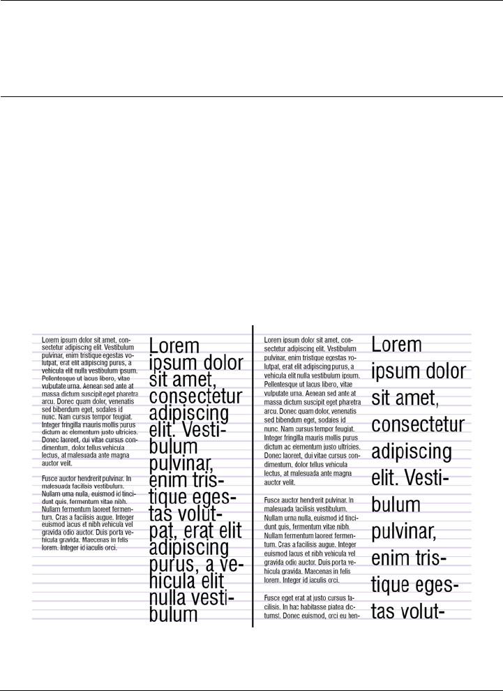
Adding and manipulating text 467
Aligning text by using the baseline grid
You can align text within a frame or in different frames by using the baseline grid. This
is useful, for example, when you want to align two or more text frames that contain
different fonts, font sizes, and spacing.
All objects can snap to the baseline grid; only text frames can align to the baseline grid.
Snapping is turned on or off for all objects (it’s a grid setting). Alignment is turned on
or off for individual frames (it’s a text frame setting). For information about displaying
or hiding the baseline grid, turning snapping on or off, changing the grid color, and
setting the line spacing, see “Setting up the baseline grid” on page 606.
Text columns with different fonts and font sizes (left) are aligned by using the
baseline grid (right).
Ensure all text frames are Web-compatible Click To o l s Options, double-click Te x t ,
and click Paragraph text frame from the
Work spa c e list of categories. Enable the
Make all new paragraph text frames Web
compatible check box.
You can also

468 Corel DESIGNER X6 User Guide
When you align paragraph text to the baseline grid, the line spacing is adjusted
automatically so that the lines of text sit on the baseline grid. When text is aligned to
the baseline grid, the line spacing is controlled by the grid rather than by the text
properties that have been previously set. For more information about line spacing, see
“Adjusting line and paragraph spacing” on page 502.
You can set one or more text frames to align to the baseline grid. When this option is
enabled, the text in the text frame is aligned to the baseline grid when part or all of the
text frame overlaps with the drawing page. If the text frame is moved completely
outside the drawing page, the text is no longer aligned to the baseline grid.
If you align a text frame to the baseline grid and then link it to another frame, both
frames are aligned to the baseline grid. If you align one of several already linked frames
to the baseline grid, only the selected frame is aligned. For more information about
linking text frames, see “Combining and linking paragraph text frames” on page 463.
To align paragraph text to the baseline grid
1Click View Grid Baseline grid.
2Select a text frame.
3Click Te x t Align to baseline grid.
You can also right-click the text frame and choose Align to baseline grid.
You can align multiple selected frames at the same time.
Selecting text
Corel DESIGNER lets you select text for to edit specific characters or modify it as an
object. For example, you can select specific characters to change the font or select a text
object, such as a text frame, so you can move, resize, or rotate it.
To select a text object
To Do the following
Select artistic text Using the Pick tool , click the artistic
text.
Select a text frame Using the Pick tool , click the text frame.

Adding and manipulating text 469
You can use the Pick tool to select multiple text objects. Hold down Shift,
and click each text object.
To select text for editing
Finding, editing, and converting text
You can find text in a document and replace it automatically. You can also find special
characters, such as an em dash or optional hyphen. You can edit text directly in the
drawing window or in a dialog box.
Corel DESIGNER lets you convert artistic text to paragraph text if you require more
formatting options, and paragraph text to artistic text if you’d like to apply special
effects.
You can also convert both paragraph and artistic text to curves. By transforming
characters into lines or curve objects, you can add, delete, or move the nodes of
individual characters to alter their shape. For more information, see “Working with
curve objects” on page 191.
When you convert text to curves, the appearance of the text is preserved, including font,
style, character position and rotation, spacing, and any other text settings and effects.
Any linked text objects are also converted to curves. If you convert paragraph text in a
fixed-sized text frame to curves, any text that overflows the text frame is deleted. For
information about fitting text to a text frame, see “Formatting text” on page 483.
To find text
1Click Edit Find and replace Find text.
2Type the text that you want to find in the Find box.
If you want to find the exact case of the text that you specified, enable the
Match case check box.
To Do the following
Select specific characters of artistic or
paragraph text for editing
Using the Te x t tool , drag across the text.
Select a text frame for editing Using the Te x t tool , click the text frame.
470 Corel DESIGNER X6 User Guide
3Click Find next.
You can also find special characters by clicking the right arrowhead next to the
Find box, choosing a special character, and clicking Find next.
To find and replace text
1Click Edit Find and replace Replace text.
2Type the text that you want to find in the Find box.
If you want to find the exact case of the text that you specified, enable the
Match case check box.
3Type the replacement text in the Replace with box.
4Click one of the following buttons:
• Find next — finds the next occurrence of the text that is specified in the Find
box
• Replace — replaces the selected occurrence of the text that is specified in the
Find box. If no occurrence is selected, Replace finds the next occurrence.
• Replace all — replaces every occurrence of the text that is specified in the Find
box
To edit text
1Click the Te x t tool .
2Perform a task from the following table.
Text that has been converted to curves cannot be edited.
You can also edit text by clicking Te x t Edit text, and making changes to the
text in the Edit text dialog box.
To Do the following
Edit artistic text Click in the artistic text.
Edit paragraph text Click in the text frame.
Adding and manipulating text 471
To convert text
Paragraph text cannot be converted to artistic text when it’s in a linked frame
or has special effects applied to it.
You can also convert text to curves by clicking the Pick tool , right-clicking
the text, and clicking Convert to curves.
Shifting, rotating, mirroring, and flipping text
You can shift the characters of artistic and paragraph text vertically or horizontally or
rotate them to create interesting effects.You can straighten characters into their original
position, and you can return vertically shifted characters to the baseline. You can also
mirror or flip artistic and paragraph text characters.
If you want to adjust the position of an entire text object that is fitted to a path, such
as a circle or a freehand line, see “To adjust the position of text that is fitted to a path”
on page 477.
To Do the following
Convert paragraph text to artistic text Using the Pick tool , select the text, and
click Te x t Convert to artistic text.
Convert artistic text to paragraph text Using the Pick tool , select the text, and
click Te x t Convert to paragraph text.
Convert artistic or paragraph text to curves Using the Pick tool , select the text, and
click Arrange Convert to curves.
472 Corel DESIGNER X6 User Guide
Rotated characters
To shift or rotate a character
1Using the Te x t tool , select the character or characters.
2In the Property manager docker, click the Character button to display the
character-related options.
To d i s p l a y t h e Property manager docker, click Window Property manager.
3Click the arrow button at the bottom of the Character area to display
additional options.
4Type a value in one of the following boxes:
• Horizontal character offset — A positive number moves characters to the
right, and a negative number moves characters to the left.
• Vertical character offset — A positive number moves characters up, and a
negative number moves characters down.
• Character angle — A positive number rotates characters counterclockwise, and
a negative number rotates characters clockwise.
You can also use the Shape tool to shift or rotate characters. Select the
character node or nodes, and then type values in the Horizontal character
offset box , Vertical character offset box , or Character angle box
on the property bar.
To straighten a shifted or rotated character
1Using the Te x t tool , select one or more characters.
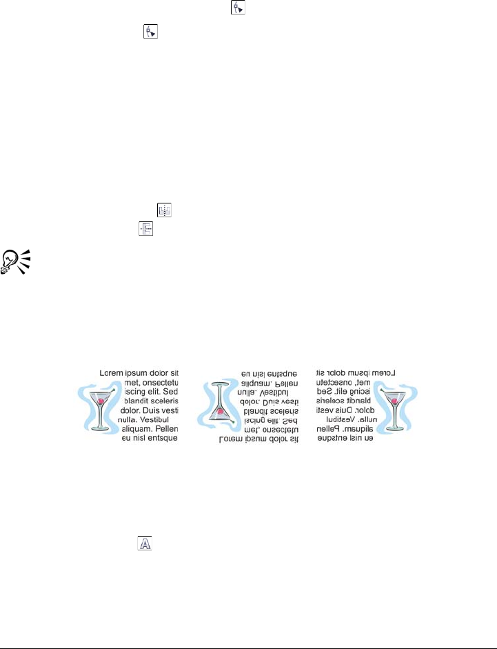
Adding and manipulating text 473
2Click Te x t Straighten text.
To return a vertically shifted character to the baseline
1In the toolbox, open the Shape tool flyout.
2Click the Shape tool .
3Select the text object, and select the node to the left of the shifted character.
4Click Te x t Align to baseline.
To mirror text
1Using the Pick tool, select a text object.
2Click View To o l b a r s Tr a n s f o r m .
3On the Tr a n s f o r m toolbar, click one of the following buttons.
• Mirror horizontally — flips the text characters from left to right
• Mirror vertically — flips the text characters from top to bottom
You can also mirror text by holding down Ctrl and dragging a selection handle
to the opposite side of the object.
You can also mirror text fitted to a path. For more information, see “To mirror
text that is fitted to a path” on page 478.
Left to right: Text in original form, mirrored vertically, and mirrored
horizontally
To flip text by dragging diagonally
1Using the Te x t tool , select the artistic text or the paragraph text frame.
2Drag a middle selection handle across the text and past the corner handle on the
opposite side.
474 Corel DESIGNER X6 User Guide
Moving text
Corel DESIGNER lets you move paragraph text between frames, and artistic text
between artistic text objects. Conversely, you can move paragraph text to an artistic text
object, or artistic text to a paragraph text frame.
To move a text object
1Click the Pick tool .
2Drag the text object to a new position in the drawing window.
To move a text selection
1Click the Te x t tool .
2Select the text that you want to move.
3Perform a task from the following table.
Wrapping text
You can change the shape of text by wrapping paragraph text around an object, artistic
text, or a text frame. You can wrap text by using contour or square wrapping styles. The
contour wrapping styles follow the curve of the object. The square wrapping styles
To Do the following
Move text within the same text object Drag the text to a new position within the
text object. The text cursor appears to
indicate the insertion point.
Move the text to another text object. Drag the text to another text object. The
text cursor appears to indicate the insertion
point.
Move or copy selected text to a new text
object
With the right mouse button, drag the text
to a new position, release the mouse button,
and click Copy here or Move here.
Move an individual character freely in the
drawing window
Click the Shape tool , select the text
object, and drag a character’s selection
handle in the lower-left corner of the
character.
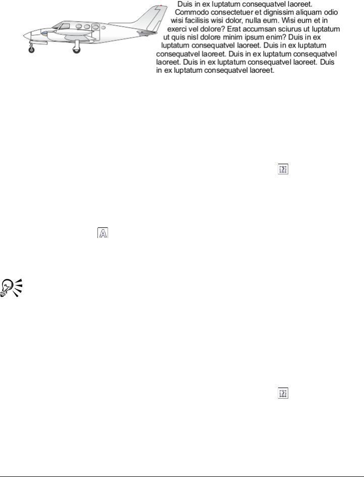
Adding and manipulating text 475
follow the bounding box of the object. You can also adjust the amount of space between
paragraph text and the object or text, and you can remove any previously applied
wrapping style.
Text wrapped around an object by using the contour wrapping style
To wrap paragraph text around an object, artistic text, or a text frame
1Select the object or text around which you want to wrap text.
2Click Window Property manager.
3In the Property manager docker, click the Summary button .
4Choose a wrapping style from the Wrap paragraph text list box.
If you want to change the amount of space between wrapped text and the object or
text, change the value in the Te x t w r a p o f f s e t box.
5Click the Te x t tool , and drag over the object or text to create a paragraph text
frame.
6Type text in the text frame.
You can wrap existing paragraph text around a selected object by applying a
wrapping style to the object and dragging the text frame over the object.
To remove a wrapping style
1Select the wrapped text or the object it wraps.
2Click Window Property manager.
3In the Property manager docker, click the Summary button .
4Choose None from the Wrap text list box.
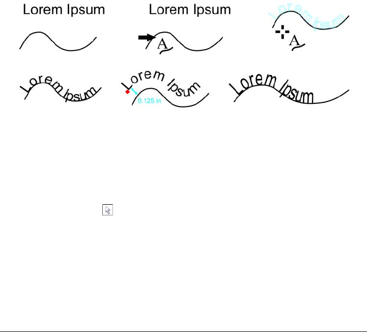
476 Corel DESIGNER X6 User Guide
Fitting text to a path
You can add artistic text along the path of an open object (for example, a line) or a closed
object (for example, a square). You can also fit existing text to a path. Paragraph text in
a text frame can be fitted to open paths only.
After you fit text to a path, you can adjust the text position relative to that path. For
example, you can mirror the text horizontally, vertically, or both. Using tick spacing,
you can specify an exact distance between the text and the path.
Corel DESIGNER treats text fitted to a path as one object; however, you can separate
the text from the object if you no longer want it to be part of the path. When you
separate text from a curved or closed path, the text retains the shape of the object to
which it was fitted. You can also modify the text and path properties independently.
The text reverts to its original appearance when you straighten it.
Text and curve as separate objects (upper left), choosing a path with the Fit
Text to Path pointer (upper middle), aligning text while fitting it to path
(upper right), text fitted to path (lower left), interactive feedback about offset
distance (lower middle), and text and curve stretched horizontally by 200%
(lower right)
To add text along a path
1Using the Pick tool , select a path.
2Click Te x t Fit text to path.
The text cursor is inserted on the path. If the path is open, the text cursor is
inserted at the beginning of the path. If the path is closed, the text cursor is
inserted at the center of the path.
3Type along the path.

Adding and manipulating text 477
Text cannot be added to the path of another text object.
You can also fit text to a path by clicking the Te x t tool and pointing to a
path. When the pointer changes to a Fit Text to Path pointer, click where you
want the text to begin, and type.
To fit text to a path
1Using the Pick tool , select a text object.
2Click Te x t Fit text to path.
The pointer changes to the Fit Text to Path pointer . By moving the pointer over
the path, you can preview where the text will be fitted.
3Click a path.
If the text is fitted to a closed path, the text is centered along the path. If the text is
fitted to an open path, the text flows from the point of insertion.
Artistic text can be fitted to open or closed paths. Paragraph text can be fitted
to open paths only.
Text cannot be fitted to the path of another text object.
To adjust the position of text that is fitted to a path
1Using the Pick tool , select the text that is fitted to a path.
2Choose a setting from any of the following list boxes on the property bar:
• Te x t o r i e n t a t i o n — specifies how the text bends to follow the path
• Distance from path — distance between the text and the path
• Offset — horizontal position of the text along the path
478 Corel DESIGNER X6 User Guide
To mirror text that is fitted to a path
1Using the Pick tool , click the text that is fitted to a path.
2In Mirror text area of the property bar, click one of the following buttons:
• Mirror text horizontally — flips the text characters from left to right
• Mirror text vertically — flips the text characters upside down
You can apply a 180-degree rotation to text that is fitted to a path by clicking
both the Mirror text horizontally and the Mirror text vertically buttons.
To separate text from a path
1Using the Pick tool , select the path and the fitted text.
2Click Arrange Break text apart.
You can also
Use tick spacing to increase the distance
between the path and the text in specified
increments
Select the text. On the property bar, click
Tick snapping, enable the Tick snapping
on option, and type a value in the Tick
spacing box.
When you move the text from the path, it
moves in the increment you specified in the
Tick spacing box. When you move the text,
the distance from the path is displayed below
the original text.
Change the horizontal position of fitted text Using the Shape tool , select the text, and
drag the character nodes that you want to
reposition.
Move fitted text along or off the path Using the Pick tool , drag the red glyph
that appears next to the text.
When you drag the glyph along the path, a
preview of the text is displayed. When you
drag the glyph off the path, the distance
between the text preview and the path is
displayed.

Adding and manipulating text 479
To straighten text
1Using the Pick tool , select the path and the fitted text.
2Click Arrange Break text apart.
3Using the Pick tool, select the text.
4Click Te x t Straighten text.
Embedding graphics and adding special characters
You can embed a graphic object or bitmap in text. The graphic object or bitmap is
treated as a text character. As a result, you can apply formatting options according to
the type of text in which you embed the graphic object. You can also remove an
embedded object from text, after which the object returns to its original state.
You can also add special characters as text or as graphic objects. When you add special
characters as text, you can format the characters as you do the text. When you add
special characters as graphic objects, the characters are curves. Consequently, you can
edit them as you would other graphic objects.
To embed a graphic object in text
1Select a graphic object.
2Click Edit, and click one of the following:
• Cut
• Copy
3Using the Te x t tool , click where you want to embed the graphic object.
4Click Edit Paste.
To remove an embedded object from text
1Using the Te x t tool , select an embedded object.
2Click Edit Cut.
3Click the Pick tool , and click outside the text object.
4Click Edit Paste.

480 Corel DESIGNER X6 User Guide
To add a special character as a text object
1Using the Te x t tool , click where you want to add the special character.
2Click Te x t Insert symbol character.
3In the Insert character docker, choose a font from the Font list box.
4Double-click a character in the list.
The size of the character is determined by the font size of the text.
The Insert character docker displays the keyboard shortcuts that you can use
to add special characters.
To add a special character as a graphic object
1Click Te x t Insert symbol character.
2In the Insert character docker, choose a font from the Font list box.
3Type a value in the Character size box.
4Drag a special character from the list to the drawing window.
The special character is inserted with the default graphic style. For information
about graphic styles, see “Working with styles and style sets” on page 569.
Working with legacy text
If a document contains text and was created in a previous version of Corel DESIGNER,
such as Corel DESIGNER X5, you must update the legacy text before you can use new
text features such as OpenType options and aligning text with the baseline grid. For
more information, see “Working with OpenType features” on page 494 and “Aligning
text by using the baseline grid” on page 467.
To update legacy text
1Open the document with legacy text.
An Update toolbar appears at the top of the drawing window.
2Click Update.
To undo the update, click Undo on the Update toolbar. However, once you make
changes to the updated text, this option is no longer available.

Adding and manipulating text 481
When legacy text is updated, its flow and layout may change.
You can also update legacy text by clicking the Update button in the
Character area of the Property manager docker.

Formatting text 483
Formatting text
The Corel DESIGNER application lets you use text to create documents or annotate
drawings.
This section contains the following topics:
• Choosing typefaces and fonts
• Formatting characters
•Changing text color
• Kerning a range of characters
•Changing text case
• Working with OpenType features
• Adjusting character and word spacing
• Adjusting line and paragraph spacing
• Adding bullets to text
•Inserting drop caps
• Changing character position and angle
• Aligning text
• Adding tabs and indents
• Working with text styles
• Hyphenating text
• Inserting formatting codes
• Displaying nonprinting characters
Choosing typefaces and fonts
Text is an important element in the design and layout of documents. In
Corel DESIGNER, you can choose the typeface that is best suited to your project. You
can specify the font size and style. In addition, you can use an OpenType font to achieve
a unique and distinctive style. For more information, see “Working with OpenType

484 Corel DESIGNER X6 User Guide
features” on page 494. The default unit of measure for text is points; however, you can
change the unit of measure for the active drawing and all subsequent drawings. For
information about previewing fonts, see “Previewing and displaying fonts” on
page 531.
Fonts vs. typefaces
“Font” and “typeface” are two typography terms that are often used interchangeably,
but they do not have the same meaning. A font is a collection of characters that includes
letters, numbers, and symbols of one variation of a typeface, such as bold or italic. A
typeface, which is also known as a font family, is made up of several fonts that share
similar design characteristics. In other words, a font is the mechanism that allows you
to render the characters onscreen or in print, whereas the typeface, which embodies the
style and visual distinctiveness of the characters, refers to the design and style of the
type.
The following table lists a few examples of typefaces and fonts. just as in type a font is
the delivery mechanism and a typeface is the creative work.
Choosing a typeface
Typefaces come in different shapes and sizes and have unique characteristics and
expressive qualities. Choosing the right typeface is an important design consideration
because it can set the tone of the project. Moreover, it can help, or hinder, effective
communication. For example, if you design a poster with a typeface that is difficult to
read, or sets the wrong tone, your message may not effectively reach your intended
audience.
Here are a few basic tips for choosing the right typeface:
• Choose a typeface that best suits the tone of your design.
• Choose a typeface that is appropriate for the final output of your design (e.g. web
or print).
• Use less typefaces in your document. The general rule is not to exceed three or four
typefaces in a document.
Typeface (Font family) Font
Helvetica Helvetica Bold-Italic
Times New Roman Normal
Ve r d a n a Ve r d a n a B o l d - I t a li c
Formatting text 485
• Make sure the typeface characters are easy to read and recognize.
• Choose a typeface that is appropriate for the age of your target audience.
• Make sure the typeface of headings stands out and looks good when displayed at
larger sizes.
• Make sure the typeface of body text enhances readability.
• Choose a typeface that supports multiple languages if you’re working on
multilingual documents.
To change the font
1Using the Te x t tool , select a character or a block of text.
If the Property manager docker is not open, click Window Property manager.
2In the Property manager docker, click the Character button to display the
character-related options.
3In the Character area of the Property manager docker, perform one or more tasks
from the following table.
The method of “greeking” text helps increase the redraw speed, which is useful
for creating prototypes of documents or drawings. You can make text readable
again by reducing the greeking value or by zooming in on the text.
You can also change the font and font size from the property bar.
You can also change the font style of selected text by clicking the Bold
button , Italic button , or Underline button on the property bar.
To Do the following
Choose a typeface Choose a typeface from the Font list box.
Set font size Type a value in the Font size box.
Change the font style Choose a style from the Font style list box.
Use lines to represent text that is smaller
than a specific font size
Click To o l s Options, click Te x t in the
Work spa c e list of categories, and then type
a value in the Greek text below box.
486 Corel DESIGNER X6 User Guide
To resize text
1Using the Te x t tool , select a character or a block of text.
2On the property bar, choose a size from the Font size list box.
You can also resize the text from the Character area of the Property manager
docker, by choosing a size from the Font size list box.
Formatting characters
You can change the position and appearance of characters by displaying them as
subscript or superscript, which is useful in drawings with scientific notations. If you
select an OpenType font that supports subscript and superscript, you can apply the
OpenType feature. However, if you select a font, including an OpenType font, that does
not support subscript and superscript, you can apply a synthesized version of the
character, which Corel DESIGNER produces by altering the characteristics of the
You can also
Resize artistic text using the Pick tool Click the Pick tool , and drag one of the
corner handles.
Resize paragraph text using the Pick tool Click the Pick tool , press Alt, and then
drag one of the corner handles.
Increase the size of text Press Num Lock to activate the number pad
on your keyboard, and use the Te x t tool
to select the text. Then, hold down Ctrl, and
press 8 on the number pad.
Decrease the size of text Using the Te x t tool , select the text.
Then, hold down Ctrl, and press 2 on the
number pad.
Set an increment for resizing text Click To o l s Options. In the Wo r ksp ace
list of categories, click Te x t , and type a value
in the Keyboard text increment box.
Change the default unit of measure Click To o l s Options. In the Wor k spa ce
list of categories, click Te x t , and choose a
unit from the Default text units list box.
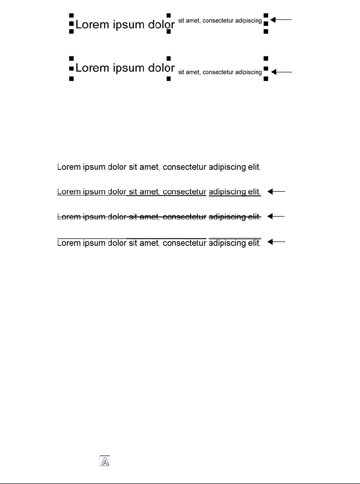
Formatting text 487
default font character. For more information, see “Working with OpenType features” on
page 494.
Artistic text with superscript (1) and subscript (2) applied
You can also add underlines, strikethrough lines, and overlines to selected characters.
Artist text with underline (1), strikethrough (2), and overline (3) applied to
the text using both single and double line styles.
If you want to reuse the formatting of selected text, you can use styles or copy the text
attributes and apply them to another text selection. For more information, see
“Working with styles and style sets” on page 569 and “Copying object properties,
transformations, and effects” on page 253.
You can modify the behavior of the text cursor that displays onscreen and enable text
highlighting, which is useful when formatting text.
In addition, you can change the text color and add a background color to paragraph text
frames, the bounding box of artistic text, or selected text characters.
To insert superscript or subscript text
1Using the Te x t tool , select a character or a block of text.
1
2
1
2
3

488 Corel DESIGNER X6 User Guide
If the Property manager docker is not open, click Window Property manager.
2In the Property manager docker, click the Character button to display the
character-related options.
3In the Character area of the Property manager docker, click the Position button,
and choose one of the following options.
• None — turns off all the features in the list
• Superscript (auto) — applies the OpenType feature if the font supports it, or
applies a synthesized version if the font does not support superscript
• Subscript (auto) — applies the OpenType feature if the font supports it, or
applies a synthesized version if the font does not support subscript
• Superscript (synthesized) — applies a synthesized version of the superscript
feature, which looks the same as in previous versions of Corel DESIGNER
• Subscript (synthesized) — applies a synthesized version of the subscript
feature, which looks the same as in previous versions of Corel DESIGNER
Some OpenType fonts may appear to support features that are unsupported.
For example, Superscript and Subscript options may appear available, but are
not. If you apply one of these OpenType fonts, Corel DESIGNER cannot
provide a synthesized version of Superscript and Subscript.
To underline, overline, or strikethrough text
1Using the Te x t tool , select a character or a block of text.
If the Property manager docker is not open, click Window Property manager.
2In the Property manager docker, click the Character button to display the
character-related options.
3In the Character area of the Property manager docker, click the arrow button
located at the bottom of Character area to display the additional character options.
4Perform one or more tasks from the following table.
To Do the following
Underline text Click the Underline button and choose a
style from the list box.
Apply a line through the selected text Choose a style from the Character
strikethrough list box.
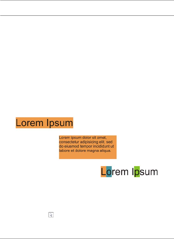
Formatting text 489
To modify the text cursor behavior
1Click To o l s Options.
2In the list of categories, click Te x t .
3In the Te x t c u r s o r area, enable any of the following check boxes:
• Highlight formatting changes
• Enhanced text cursor
Changing text color
You can quickly change both the fill and outline color of text. You can change the fill,
outline, and background color of text. You can change the color of individual characters,
a block of text, or all characters in a text object.
Left to right: Background color is applied to artistic text, paragraph text, and
selected characters
To quickly change the color of a text object
1Using the Pick tool , click a text object to select it.
2Perform a task from the following table.
Apply a line above the selected text. Choose a style from the Character overline
list box.
To Do the following

490 Corel DESIGNER X6 User Guide
To change the color of a text selection
1Using the Te x t tool , select a character or a block of text.
If the Property manager docker is not open, click Window Property manager.
2In the Property manager docker, click the Character button to display the
character-related options.
3In the Character area of the Property manager docker, perform one or more tasks
from the following table.
To Do the following
To fill characters in a text object with one
color
Click any color swatch on the default color
palette or drag a color swatch to the text
object.
To apply an outline color to all characters in
a text object
Right-click any color swatch on the default
color palette or drag a color swatch to the
edge of a character in the text object.
To Do the following
Choose a fill color In the text color area, choose a fill from the
Fill type list box, open the Te x t c o l o r
picker, and then click a color.
Modify fill settings In the text color area, click the Fill settings
button , and modify the settings in the
dialog box.
Choose a background fill color In the text background color area, choose a
fill from the Background fill type list box,
open the Text background color picker,
and then click a color.
Modify background fill settings In the text background color area, click the
Fill settings button, and modify the settings
in the dialog box.
Choose an outline width In the text outline color area, click the
Outline width button, and choose an option
from the list.
Formatting text 491
To add a background color to text
You can also add a background color to text by using the Background color
controls in the Character area of the Property manager docker. To access the
Property manager docker, click Window Property manager.
Kerning a range of characters
You can kern pairs of selected characters. Kerning refers to the repositioning of two
characters to balance the optical space between them. For example, kerning is often
used to decrease the space in character pairs such as AW, WA, VA, or TA. Such character
pairs are known as “kerning pairs.” Kerning increases readability and makes letters
appear balanced and proportional, especially at larger font sizes.
Choose an outline color In the text outline color area, click the
Outline color picker, and click a color.
Modify line outline settings In the text outline color area, click the
Outline settings button , and modify the
settings in the Outline pen dialog box.
To Do the following
Add a background color to paragraph or
artistic text
Using the Pick tool , select the text.
Open the Background color picker on the
property bar, and pick a color.
Add a background color to specific
characters
Using the Te x t tool , select the characters.
Open the Character background color
picker on the property bar, and pick a color.
To Do the following

492 Corel DESIGNER X6 User Guide
Decreasing the kerning between two characters
To kern text
1Using the Te x t tool , select the characters that you want to kern.
If the Property manager docker is not open, click Window Property manager.
2In the Property manager docker, click the Character button to display the
character-related options.
3In the Character area of the Property manager docker, type a value in the Range
kerning box.
Negative values decrease the spacing between characters; positive values increase
the spacing between characters.
Changing text case
Corel DESIGNER lets you change the text case of artistic and paragraph text. For
example, you can apply small caps to acronyms so they visually blend with the text. If
you apply default capitalization, the text stands out too much and impacts the
readability. In the following example, the acronym “A.M.” is shown with both the
default uppercase and small caps applied.
You control the case of words, sentences, or paragraphs of selected text. For example,
you can apply title case to selected text to capitalize the initial letter of every word. This
is a useful formatting technique for headings, such as book or chapter titles.
Default uppercase Small caps
The class begins at 9:00 A.M. in room 132. The class begins at 9:00 A.M. in room 132.

Formatting text 493
You can automatically convert text to lowercase or uppercase without deleting or
retyping letters. For example, if you accidentally pressed the Caps Lock key and added
uppercase text, you can convert the text to lowercase without retyping it.
To change the text case
1Using the Te x t tool , select a character or a block of text.
If the Property manager docker is not open, click Window Property manager.
2In the Property manager docker, click the Character button to display the
character-related options.
3In the Character area of the Property manager docker, click the Caps button,
and click one of the following options:
• None — turns off all of the features in the list
• All caps — substitutes lowercase characters with upper case equivalents
• Titling caps — applies the OpenType version of the feature if the font supports
it
• Small caps (auto) — applies the OpenType version of the feature if the font
supports it
• All small caps — substitutes characters with a scaled-down version of the upper
case characters
• Small caps from caps — applies the OpenType version of the feature if the font
supports it
• Small caps (synthesized) — applies a synthesized version of Small caps, which
appears the same as in previous versions of Corel DESIGNER
If you choose a non-OpenType that supports Caps styles, Corel DESIGNER
provides a synthesized version of the Small caps and All small caps styles.
Some OpenType fonts may appear to support features that are unsupported.
You can also change text case by selecting a character or a block of text,
clicking Te x t Change case, and enabling an option in the Change case
dialog box.
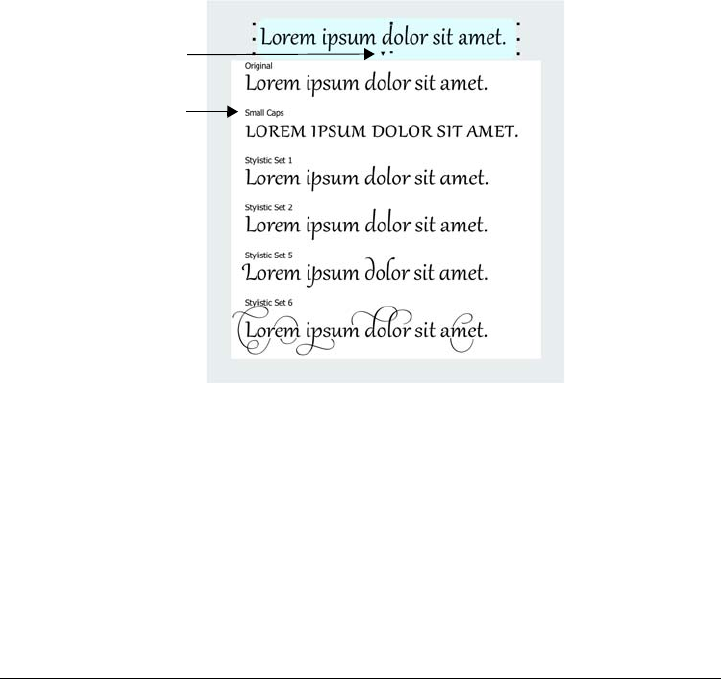
494 Corel DESIGNER X6 User Guide
Working with OpenType features
Corel DESIGNER supports OpenType fonts so you can take advantage of their
advanced typographic features. OpenType features allow you to choose an alternate
appearance for an individual character (also referred to as a glyph) or a sequence of
characters. For example, you can choose alternate glyphs for numbers, fractions, or
ligature sets.
You can access OpenType commands and options in the Character area of the Property
manager docker. You can also let Corel DESIGNER prompt you which OpenType
features you can apply by enabling the Interactive OpenType option. When you select
text, an indicator arrow appears below the text if an OpenType feature is available. You
can click the indicator to access a list of the most popular OpenType features that are
available for the selected text.
Clicking the Interactive OpenType indicator arrow (1) expands a list of the
most popular OpenType features that are available for the selected text.
The OpenType font specification was created jointly by Adobe and Microsoft. Based on
Unicode, OpenType fonts extend the capabilities of older font technologies. The most
notable advantages of OpenType are:
• cross-platform support (Windows and Mac)
• extended character sets that offer better language support and advanced
typographic features
• coexistence with Type 1 (PostScript) and TrueType fonts
1
2
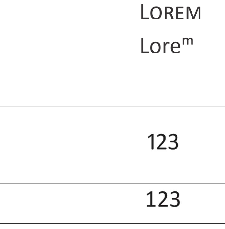
Formatting text 495
• support for a larger glyph limit (64k)
OpenType features
The following table describes the OpenType features that you can apply in
Corel DESIGNER provided that the feature is included in the font.
In addition, Corel DESIGNER also provides synthesized versions of some Caps and
Position OpenType features. For example, if a font does not support a feature, such as
Small Caps, Corel DESIGNER produces its own version of the glyph by scaling the
font.
OpenType feature Description Example
Caps Changes the case of text, which
is useful for inserting titles and
acronyms Small caps
Position Displays characters as
superscript or subscript, which is
useful for inserting footnotes or
mathematical symbols. If you
select an OpenType font that
does not support subscript and
superscript, or a non-OpenType
font, you can apply a synthesized
glyph.
Superscript
Number styles Includes features for controlling
the appearance of numbers
See examples below
Number styles —
Proportional lining
Displays numbers of varying
width, which is best suited for
inserting numbers in body text.
However, the numbers have a
fixed height, which generally
matches the height of capital
letters.
Number styles —
Tabular lining
Displays numbers of equal
width, spacing, and height,
which is useful for aligning text
and displaying text in a table

496 Corel DESIGNER X6 User Guide
Number styles —
Proportional
Oldstyle
Displays numbers of varying
width and height. The style is
best suited for blending numbers
with mixed text case.
Number styles —
Tabular Oldstyle
Displays numbers of equal
width, but varying height
Fraction Displays numbers separated by a
slash as fractions. The number of
available fractions vary from font
to font. Apply this feature only
to the numbers that you want to
display as a fraction.
See examples below
Fraction —
Numerator
Displays a numerator, such as
456/, as a fraction glyph. This is
useful for displaying a non-
standard fraction, such as 456/
789, as a fraction. Use the
Numerator feature in
conjunction with the
Denominator feature to display
non-standard fractions as
fractions.
Fraction —
Denominator
Displays a denominator, such as
/789, as a fraction glyph. This is
useful for displaying a non-
standard fraction, such as 456/
789, as a fraction. Use the
Denominator feature in
conjunction with the Numerator
feature to display non-standard
fractions as fractions.
OpenType feature Description Example
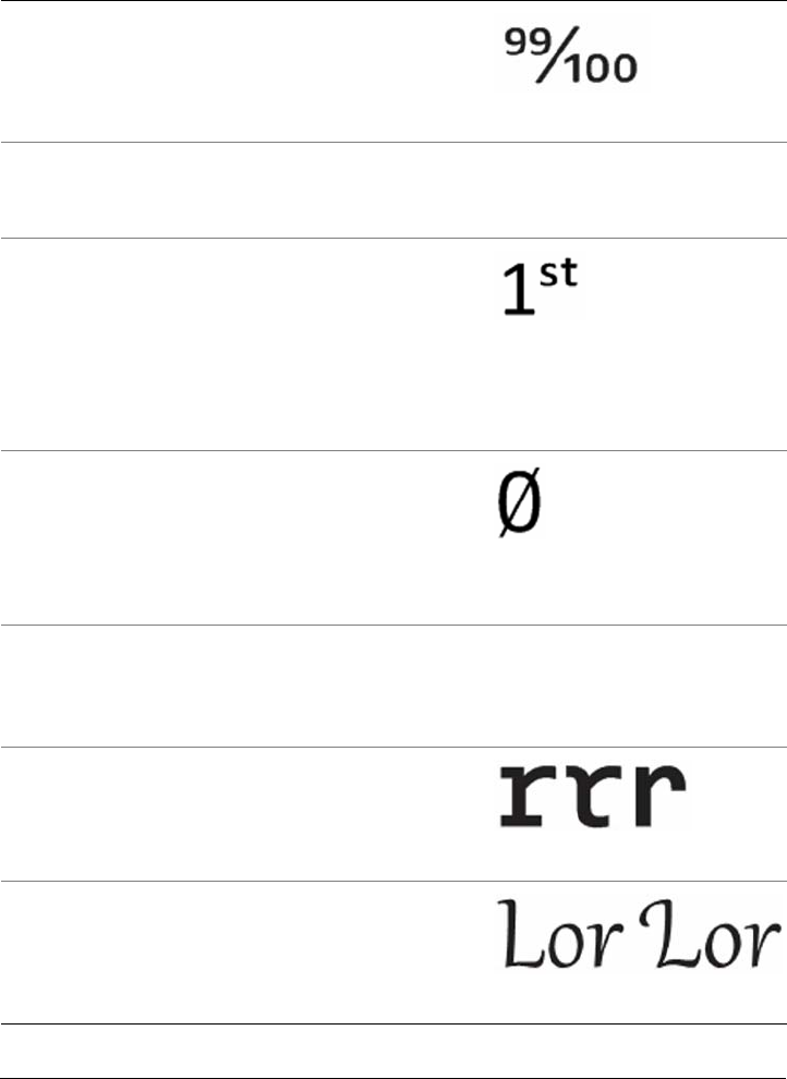
Formatting text 497
Fraction — Fraction Displays standard fractions as
fraction glyphs
Fraction —
Alternative fraction
Displays a fraction by using a
horizontal dividing line instead
of a slant or slash
Not available
Ordinals Displays ordinals by using a
number and a suffix in
superscript. For example, you
can display “first” as 1st or
“second” as 2nd. Apply this
feature only to the text that you
want to display as an ordinal.
Slashed zero Displays zeros with a diagonal
slash, which makes them easy to
distinguish from the letter O.
This feature is useful for
displaying numbers in financial
reports.
Ornaments Substitutes a character with an
ornament that was created by
the font designer to match the
font’s motif
Not available
Stylistic alternates Applies an alternate design to
characters
Stylistic sets Applies an alternate design to a
text selection
OpenType feature Description Example
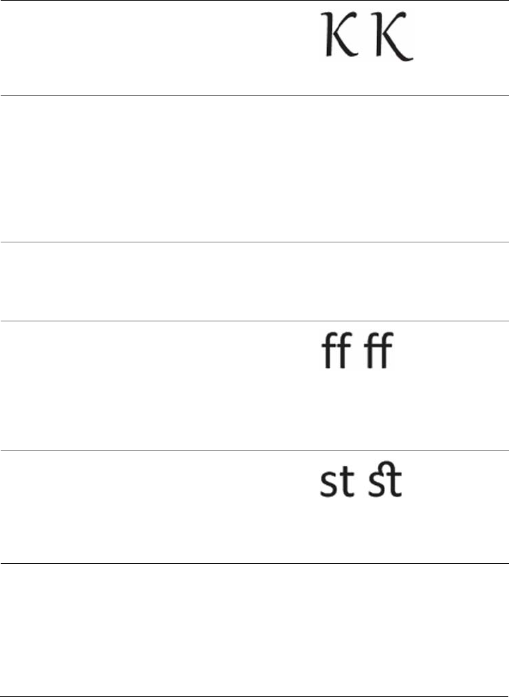
498 Corel DESIGNER X6 User Guide
Swash Variants Inserts calligraphic-type
decorative characters
Contextual alternates Lets you fine-tune text by
applying an alternate design to a
single character, or a sequence of
characters, based on its
surrounding characters. For
example, you can apply this
feature to script-based text so
that it flows more naturally.
Not available
Case-sensitive forms Shifts the position of
punctuation marks so they align
with capitalized text or lining
numbers
Not available
Standard Ligatures Replaces a letter pair (or a
sequence of letters) with one
glyph, which is called a ligature.
Many OpenType fonts include
standard ligatures for fi, fl, ff, ffi,
and ffl. Their purpose is to
improve text readability.
Discretionary
Ligatures
Replaces a non-standard letter
combination with a ligature.
Discretionary ligatures designed
to be decorative and are not
supported by the majority of
OpenType fonts.
OpenType feature Description Example

Formatting text 499
To apply an OpenType feature to text
1Using the Te x t tool , a single character or a sequence of characters.
If the Property manager docker is not open, click Window Property manager.
2In the Property manager docker, click the Character button to display the
character-related options.
3In the Character area of the Property manager docker, click an OpenType feature
button, and, if applicable, choose a feature from the list.
Some OpenType fonts may appear to support features that are unsupported.
Contextual ligatures Inserts a glyph that best suits
the surrounding characters.
Contextual ligatures are
designed to increase readability
by improving the joining
behavior between the characters
of a ligature.
Not available
Historical ligatures Substitutes a letter pair, or a
letter sequence, with a ligature
that is based on historical
usages. Historical ligatures are
designed to be ornamental and
are not supported by the
majority of OpenType fonts. The
most commonly-used historical
ligatures are the letter s
combined with another
character, such as sh si sl ss, and
st.
Not available
Historical forms Substitutes modern characters
with characters that were
commonly used in historical
documents. Historical forms are
useful for recreating historical
text.
Not available
OpenType feature Description Example
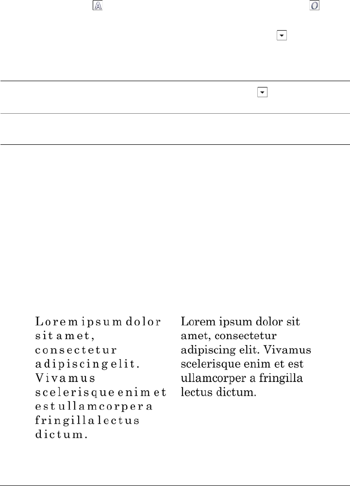
500 Corel DESIGNER X6 User Guide
To enable the onscreen OpenType feature indicator
•Click the Te x t tool , and then click the Interactive OpenType button on the
property bar.
If an OpenType feature is available for the selected text, an arrow displays below
the text.
Adjusting character and word spacing
You can improve text readability by adjusting the character and word spacing. When
letters or words are too close together, or too far apart, they become difficult to read.
Corel DESIGNER offers you different tools for controlling text spacing.
Character spacing
You can change the spacing between characters (also known as “letter spacing”) in a
block of text. For example, fully justifying a block of text may insert too much space
between characters, which creates a visual imbalance. To improve readability, you can
decrease the character spacing.
Increased character spacing (left) makes it difficult to read the text. Decreased
character spacing (right) improves readability.
You can also
View a list of the most popular OpenType
features onscreen
Click the down arrow below the text in
the document window.
Apply an OpenType feature to a text
selection
Hover over an option in the OpenType
feature list, and click an option.
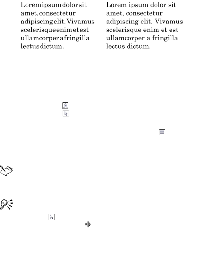
Formatting text 501
If you want to change the spacing between several characters, you need to adjust the
kerning. For more information, see “Kerning a range of characters” on page 491.
Word spacing
You can also adjust the spacing between words.
Decreased word spacing makes it difficult to discern the individual words in a
paragraph (left). Increased word spacing (right) makes easier to read the
paragraph.
To adjust character spacing
1Do one of the following:
• Using the Te x t tool , position the cursor in a block of text.
• Using the Pick tool , click an artistic text object or a text frame.
If the Property manager docker is not open, click Window Property manager.
2In the Property manager docker, click the Paragraph button to display the
paragraph-related options.
3In the Paragraph area of the Property manager docker, type a value in the
Character spacing box.
Values for adjusting spacing represent a percentage of the space character. The
Character values range from -100 to 2000 percent. All other values range
from 0 to 2000 percent.
You can also change the character spacing proportionally by clicking the
Shape tool , selecting the text object, and dragging the Interactive
horizontal spacing arrow in the lower-right corner of the text object.
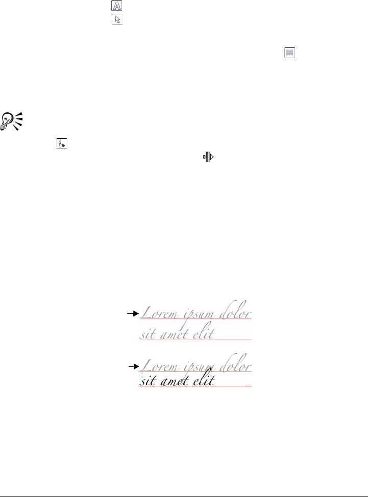
502 Corel DESIGNER X6 User Guide
To adjust word spacing
1Do one of the following:
• Using the Te x t tool , position the cursor in a block of text.
• Using the Pick tool , click an artistic text object or a text frame.
If the Property manager docker is not open, click Window Property manager.
2In the Property manager docker, click the Paragraph button to display the
paragraph-related options.
3In the Paragraph area of the Property manager docker, type a value in the Wor d
spacing box.
You can also change the word spacing proportionally by clicking the Shape
tool , holding down Shift, selecting the text object, and dragging the
Interactive horizontal spacing arrow in the lower-right corner of the text
object.
Adjusting line and paragraph spacing
You can change the spacing between lines of text, which is also known as “leading” or
“interline spacing.” When changing the line spacing for artistic text, it applies only to
the lines of text that are separated by a hard return. The line spacing of paragraph text
applies only to the lines of text within the same paragraph.
Well-balanced line spacing (1) can improve the readability of text. Insufficient
line spacing can reduce readability by causing letters to overlap (2).
In Corel DESIGNER, you can also adjust line spacing of a text object by using the
Shape tool.
1
2
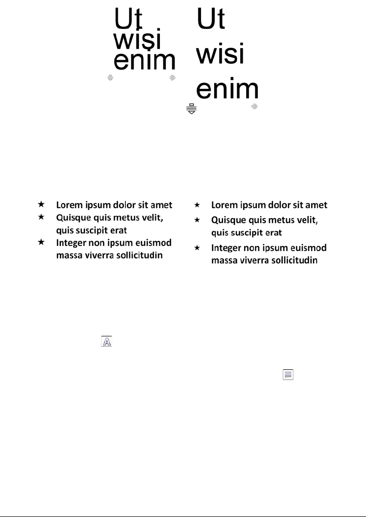
Formatting text 503
Adjusting line spacing proportionally by using the Shape tool
You can change the spacing between paragraphs, which is useful for copyfitting text. If
a paragraph is positioned at the top or bottom of a frame, the spacing does not apply to
the space between the paragraph text and the frame.
The spacing in between the lines in the bulleted list (left) was increased by
adjusting the before and after paragraph spacing (right).
To adjust interline spacing
1Using the Te x t tool , select the paragraph text.
If the Property manager docker is not open, click Window Property manager.
2In the Property manager docker, click the Paragraph button to display the
paragraph-related options.
3In the Paragraph area of the Property manager docker, choose one of the
following units of measurement from the Vertical spacing units list box:
• % of Char height — lets you use a percentage value that is relative to the
character height
• Points — lets you use points
• % of Pt.size — lets you use a percentage value that is relative to the character
point size
4Type a value in the Line spacing box.
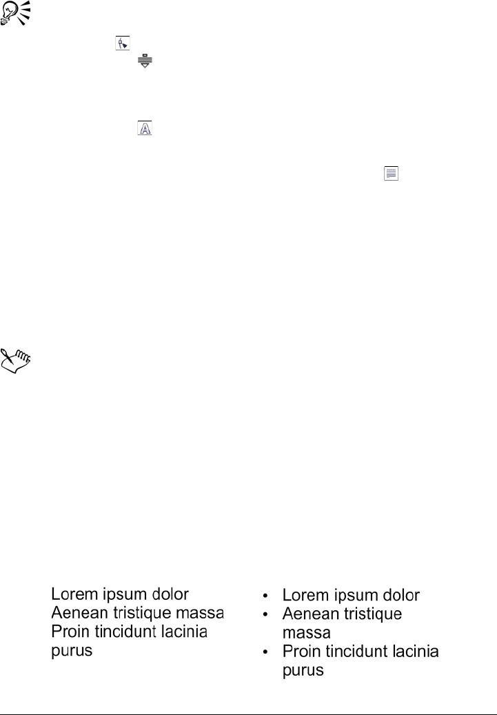
504 Corel DESIGNER X6 User Guide
You can also change the spacing between lines proportionally by clicking the
Shape tool , selecting the text object, and dragging the Interactive vertical
spacing arrow in the lower-left corner of the text object.
To adjust the spacing between paragraphs
1Using the Te x t tool , select the paragraph text.
If the Property manager docker is not open, click Window Property manager.
2In the Property manager docker, click the Paragraph button to display the
paragraph-related options.
3In the Paragraph area of the Property manager docker, choose a unit of
measurement for line spacing from the Vertical spacing units list box.
4Type a value in one of the following boxes:
• Before paragraph spacing — lets you specify the amount of space to insert
above the paragraph text
• After paragraph spacing — lets you specify the amount of space to insert
below the paragraph text
You can also use this procedure to adjust the spacing between items in a
bulleted list.
Adding bullets to text
You can use bulleted lists to format information. You can wrap text around bullets, or
you can offset a bullet from text to create a hanging indent. Corel DESIGNER lets you
customize bullets by changing their size, position, and distance from text. You can also
change the spacing between items in a bulleted list. For more information, see “To
adjust interline spacing” on page 503. You can remove a bullet without deleting the
text.
Three paragraphs (left) were converted into a bulleted list (right)
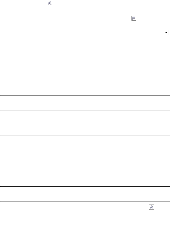
Formatting text 505
To add bullets
1Using the Te x t tool , select the paragraph text.
If the Property manager docker is not open, click Window Property manager.
2In the Property manager docker, click the Paragraph button to display the
paragraph-related options.
3In the Paragraph area of the Property manager docker, click the arrow button
located at the bottom of Paragraph area to display additional options.
4Enable the Bullets check box.
5Click the Bullet settings button.
6In the Bullets dialog box, perform a task from the following table.
To Do the following
Preview text with bullets Enable the Preview check box.
Choose a font In the Appearance area, choose a font from
the Font list box.
Choose a symbol Open the Symbol picker, and click a
symbol.
Set a bullet size Type a value in the Size box.
Adjust the bullet position Type a value in the Baseline shift box.
Set the distance from the text frame In the Spacing area, type a value in the Te x t
frame to bullet box.
Set the distance between the bullet and the
text
Type a value in the Bullet to text box.
You can also
Add a bullet with a hanging indent Enable the Use hanging indent style for
bulleted lists check box.
Change the color of a bullet Select the bullet with the Te x t tool , and
click a color on the color palette.
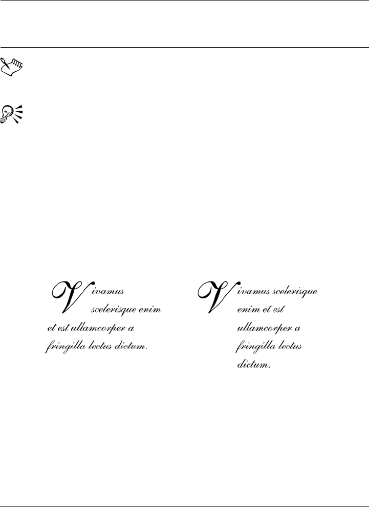
506 Corel DESIGNER X6 User Guide
Bullets are inserted at the beginning of each new line that is preceded by a
return.
You can adjust the spacing in between bullets by increasing or decreasing the
space before and after a paragraph. For more information, see “To adjust the
spacing between paragraphs” on page 504.
Inserting drop caps
Applying drop caps, also known as initial caps, to paragraphs enlarges the initial letter
and insets it into the body of text. You can customize a drop cap by changing different
settings. For example, you can change the distance between the drop cap and the body
of text, or specify the number of lines of text that you want to appear next to the drop
cap. You can remove the drop cap at any point without deleting the letter.
You can add a drop cap (left) or a hanging indent drop cap (right).
You can preview a drop cap before you add it to a drawing. The changes you make are
temporarily applied to the text in the drawing window, so you can see how the drop cap
will look when you add it.
Remove bullets In the Paragraph area of the Property
manager docker, disable the Bullets check
box.
You can also

Formatting text 507
To add a drop cap
1Using the Te x t tool , select the paragraph text.
If the Property manager docker is not open, click Window Property manager.
2In the Property manager docker, click the Paragraph button to display the
paragraph-related options.
3In the Paragraph area of the Property manager docker, click the arrow button
located at the bottom of Paragraph area to display additional options.
4Enable the Drop caps check box.
5Click the Drop caps settings button.
6In the Drop cap dialog box, perform a task from the following table.
Changing character position and angle
You can modify the appearance of text by shifting the characters vertically or
horizontally, which changes the position of the selected characters relative to the
surrounding characters.
You can also rotate characters by specifying an angle of rotation.
To D o
Specify the number of lines next to a drop
cap
In the Appearance area, type a value in the
Number of lines dropped box.
Set the distance between the drop cap and
the body of text
In the Appearance area, type a value in the
Space after drop cap box.
This sets the space to the right of the drop
cap.
Preview a drop cap Enable the Preview check box.
Offset the drop cap from the body of text Enable the Use hanging indent style for
drop cap check box.
Remove drop caps In the Paragraph area of the Property
manager docker, disable the Drop caps
check box.
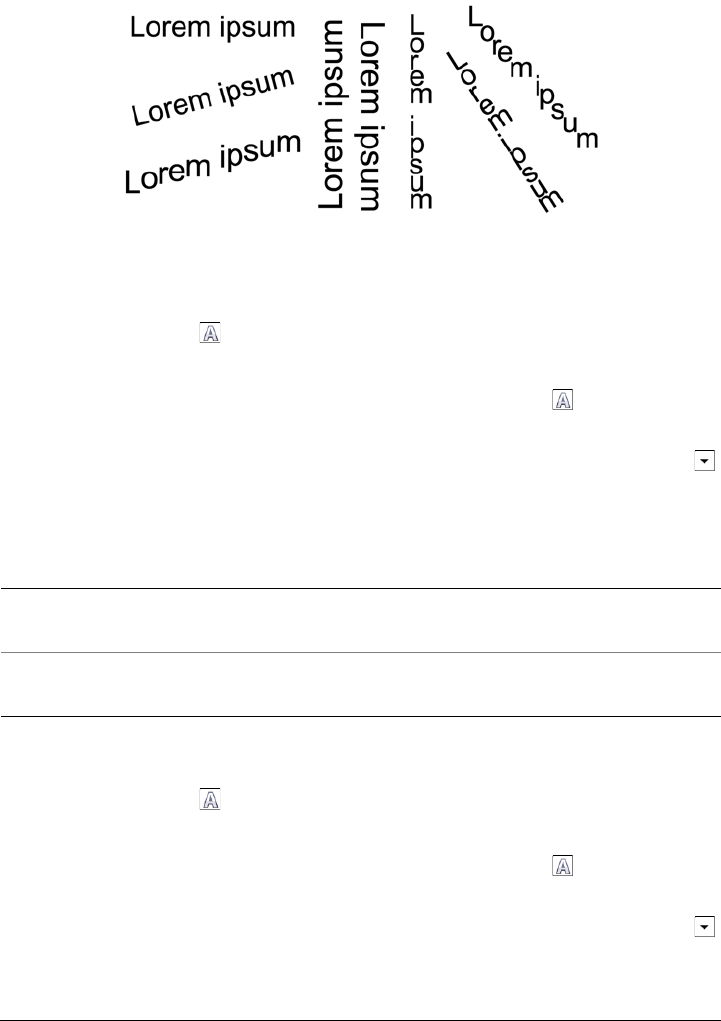
508 Corel DESIGNER X6 User Guide
Different examples of rotating text
To shift a character
1Using the Te x t tool , select a character or a block of text.
If the Property manager docker is not open, click Window Property manager.
2In the Property manager docker, click the Character button to display the
character-related options.
3In the Character area of the Property manager docker, click the arrow button
located at the bottom of Character area to display additional options.
4Perform one or more tasks from the following table.
To rotate a character
1Using the Te x t tool , select a character or a block of text.
If the Property manager docker is not open, click Window Property manager.
2In the Property manager docker, click the Character button to display the
character-related options.
3In the Character area of the Property manager docker, click the arrow button
located at the bottom of Character area to display additional options.
4Type a value in the Character angle box.
To Do the following
Shift characters horizontally Type a value in the Horizontal character
offset box.
Shift characters vertically Type a value in the Vertical character offset
box.
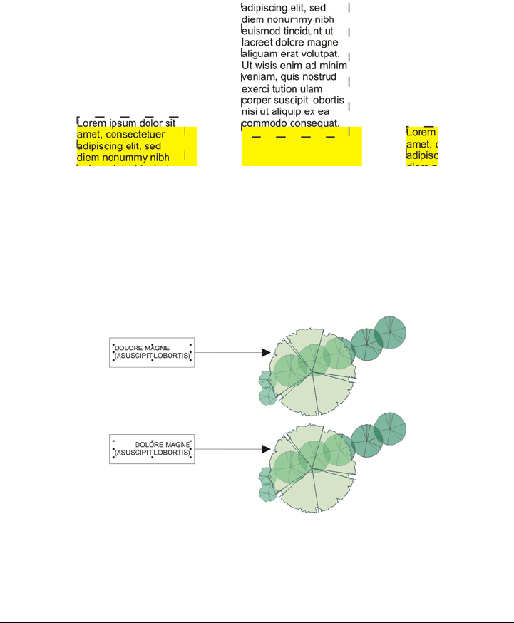
Formatting text 509
Aligning text
Corel DESIGNER lets you align text in various ways. You can align paragraph text
horizontally and vertically in relation to its text frame. You can align paragraph text
with the baseline grid. For more information, see “Aligning text by using the baseline
grid” on page 467. You can also align text to a selected object.
You can align a text object with other objects by using the baseline of the first
line, the baseline of the last line, or the edge of the text frame.
Artistic text can be aligned horizontally, but not vertically. When you align artistic text,
the entire text object is aligned in relation to the bounding box. If characters have not
been shifted horizontally, applying no alignment produces the same result as applying
left alignment.
Artistic text is aligned within the bounding box, which is indicated by eight
selection handles (black squares). The text at the top is left-aligned; the text
at the bottom is right-aligned.

510 Corel DESIGNER X6 User Guide
To align text horizontally
1Do one of the following:
• Using the Te x t tool , select the text that you want to align.
• Using the Pick tool , click an artistic text object or a text frame whose content
you want to align.
If the Property manager docker is not open, click Window Property manager.
2In the Property manager docker, click the Paragraph button to display the
paragraph-related options.
3In the Paragraph area of the Property manager docker, click one of the following
buttons:
• No horizontal alignment — applies the default alignment setting
• Align left — aligns text with the left side of the text frame or the bounding box
of artistic text
• Center — centers text within the text frame
• Align right — aligns text with the right side of the text frame and the bounding
box of artistic text
• Full justify — aligns text, with the exception of the last line, with the left and
right sides of the text frame
• Force justify — aligns text, including the last line, with the left and right sides
of the text frame
You can also align text horizontally by clicking the Horizontal alignment
button on the property bar and choosing an alignment style from the list box.
The property bar displays an icon that corresponds to the current alignment
style.
You can align multiple paragraphs in a text frame by selecting them with the
Te x t tool and choosing an alignment style.
To align paragraph text vertically
1Using the Pick tool , click a text frame.
If the Property manager docker is not open, click Window Property manager.
2In the Property manager docker, click the Frame button to display the frame-
related options.
3In the Frame area of the Property manager docker, choose an alignment option
from the Vertical alignment list box.
Formatting text 511
You can also align text vertically by clicking the Vertical alignment button on
the property bar and choosing an alignment style from the list box. The
property bar displays the alignment icon that corresponds to the current
alignment style.
To align text with an object
1Using the Pick tool , hold down Shift, click the text object, and then click the
object.
2Click Arrange Align and distribute Align and distribute.
3In the Te x t area, click one of the following buttons:
• First line baseline — uses the baseline of the first line of text to align the
objects
• Last line baseline — uses the baseline of the last line of text to align the
objects
• Bounding box — aligns text with its bounding box
4In the Align objects to area, click the Active objects button .
5In the Align area, click one of the following buttons to use an object edge or center
for aligning.
• Align left — to align the left edges of objects
• Align center horizontally — to align object centers along a vertical axis
• Align right — to align the right edges of objects
• Align top — to align the top edges of objects
• Align center vertically — to align object centers along a horizontal axis
• Align bottom — to align the bottom edges of objects
To align objects from their outlines, click the Outline button .
If you select the text objects one at a time, the last object selected is the
reference point for aligning the other objects. If you marquee select the objects
before you align them, the object that is positioned in the upper-left corner of
the selection is used.
If you have applied a linear transformation, such as rotation, to the text and are
aligning objects with a baseline, the objects align with the baseline point of the
starting edge of the text object.
512 Corel DESIGNER X6 User Guide
Adding tabs and indents
You can modify existing tab stops by changing their alignment. You can also add
trailing leader characters, so that dots, or other characters, automatically precede the
tab stops. In addition, you can add new tab stops and remove existing tab stops.
Indenting changes the space between a text frame and the text that it contains. You can
add and remove indents without deleting or retyping text. You can indent an entire
paragraph, the first line of a paragraph, or all lines of a paragraph except the first line
(a hanging indent). You can also indent from the right side of the text frame.
To modify a tab stop
1Click Window Property manager.
2In the Property manager docker, click the Paragraph button to display the
paragraph-related options.
3In the Paragraph area of the Property manager docker, click the arrow button
located at the bottom of Paragraph area to display additional options.
4Click the Tab settings button.
5Perform a task from the following table.
You can also add, move, or delete tab stops on the horizontal ruler at the top
of the drawing window. Click to add a tab stop, drag a tab marker to move it,
To Do the following
Change the alignment of tab stops Click the cell in the Alignment column, and
choose an alignment option from the list
box.
Set tab stops with trailing leader characters Click the cell in the Leaders column, and
choose On from the list box.
Delete a tab stop Click the cell, and click Remove.
Change the default leader character Click Leader options, open the Character
picker, and click a character.
Change the default leader spacing Click Leader options, and type a value in
the Spacing box.

Formatting text 513
and drag a tab marker off the ruler to delete it. For information about rulers,
see “Using the rulers” on page 602.
To add a tab stop
1Using the Te x t tool , select the paragraph text.
2Click Window Property manager.
3In the Property manager docker, click the Paragraph button to display the
paragraph-related options.
4In the Paragraph area of the Property manager docker, click the arrow button
located at the bottom of Paragraph area to display additional options.
5Click the Tab settings button.
6Click Add.
7Click the new cell in the Ta b s column, and type a value.
To indent paragraph text
1Using the Te x t tool , select the paragraph text.
2Click Window Property manager.
3In the Property manager docker, click the Paragraph button to display the
paragraph-related options.
4In the Paragraph area of the Property manager docker, type values in the
following boxes:
• First line indent — indents the first line of text relative to the left side of the
frame
• Left line indent — creates a hanging indent relative to the left side of the text
frame; all lines, except the first line, are indented
• Right line indent — indents the text relative to the right side of the frame
You can remove indents by typing 0 in the First line indent, Left line indent,
and Right line indent boxes.
You can indent an entire paragraph by typing the same value in both the First
line indent and the Left line indent boxes.
514 Corel DESIGNER X6 User Guide
Working with text styles
Corel DESIGNER provides advanced style capabilities that allow you to format
document text with speed, ease, and consistency. A style is a collection of formatting
attributes defining object properties, such as artistic and paragraph text properties. For
example, to define a character style, you can specify font type, font style and size, text
color and background color, character position, caps, and more. You can create styles
and style sets for text. You can also change the default text style, so that the same
properties are applied to all new artistic or paragraph text. For example, you can change
the font type and size, or change the text to bold or italic. For more information, see
“Working with styles and style sets” on page 569.
Hyphenating text
Hyphenation can be used to break a word if the entire word does not fit at the end of a
line. You can hyphenate automatically by using a preset hyphenation definition in
combination with your own hyphenation settings. You can set the minimum number of
characters before and after a hyphen. You can also specify the number of characters in
the “hot zone,” which is the area at the end of a line where hyphenation can occur.
You can insert an optional hyphen in a word to produce a specific word break at the end
of a line. You can also create custom definitions that specify the location of optional
hyphens in specific words whenever you type, paste, or import the words in the
application.
To hyphenate paragraph text automatically
1Using the Te x t tool , select the text frame or paragraph text.
If the Property manager docker is not open, click Window Property manager.
2In the Property manager docker, click the Paragraph button to display the
paragraph-related options.
3In the Paragraph area of the Property manager docker, click the arrow button
located at the bottom of Paragraph area to display additional options.
4Enable the Hyphenation check box.
5Click the Hyphenation settings button.
6In the Hyphenation settings dialog box, enable the Automatically hyphenate
paragraph text check box.

Formatting text 515
Hyphenation can be used for any languages that have corresponding writing
tools installed with the application. For more information about language
modules, see “Working with languages” on page 540.
If you do not see any hyphenated words in the paragraph after applying
hyphenation, you may need to modify the hyphenation settings.
To modify the hyphenation settings
1Using the Te x t tool , select the text frame or paragraph text.
If the Property manager docker is not open, click Window Property manager.
2In the Property manager docker, click the Paragraph button to display the
paragraph-related options.
3In the Paragraph area of the Property manager docker, click the arrow button
located at the bottom of Paragraph area to display additional options.
4With the Hyphenation check box enabled, click the Hyphenation settings
button.
5In the Hyphenation settings dialog box, perform one or more tasks from the
following table.
To Do the following
Hyphenate capitalized words Enable the Break capitalized words check
box.
Hyphenate words that contain all uppercase
letters
Enable the Break words using ALL CAPS
check box.
Set a minimum word length for automatic
hyphenation
In the Hyphenation criteria area, type a
value in the Minimum word length box.
This value represents the minimum number
of characters that hyphenated words must
contain.
Set the minimum number of characters to
precede a hyphen
In the Hyphenation criteria area, type a
value in the Minimum characters before
box.
516 Corel DESIGNER X6 User Guide
To insert an optional hyphen
1Using the Te x t tool , click in a word where you want to place an optional
hyphen.
2Click Te x t Insert formatting code Optional hyphen.
You can insert an optional hyphen by pressing Ctrl + -.
To create a custom definition for optional hyphenation
1Click Te x t Insert formatting code Custom optional hyphens.
2In the Wo rd box, type the word for which you want to create the hyphenation
definition.
When you type in the Wo rd box, the same text is entered in the Hyphenated
word box.
3In the Hyphenated word box, click where you want the optional hyphen inserted,
and press the Hyphen key (-).
4Click Add definition.
Set the minimum number of characters to
follow a hyphen
In the Hyphenation criteria area, type a
value in the Minimum characters after
box.
Set the “hot zone” In the Hyphenation criteria area, type a
value in the Distance from right margin
box. This value represents the number of
characters in the hot zone. A word that does
not fit within this zone is hyphenated or
moved to the next line.
You can also
Create a custom hyphen definition for a
specific language keyboard
Enable the Show all languages check box,
and choose a language option from the
Language list box.
To Do the following
Formatting text 517
The custom hyphenation definition is defined only for the language specified
in the Language list box. You can choose another language without affecting
your keyboard.
You can create a custom optional hyphen definition by selecting a word in the
document. The word appears in the Wo rd box of the Custom optional
hyphens dialog box. After you insert the optional hyphen in the Hyphenated
word box, you can apply it by clicking Apply to selection.
You can find and replace optional hyphens. For more information, see “To find
text” on page 469 and “To find and replace text” on page 470.
Inserting formatting codes
You can insert formatting codes, such as em dashes and nonbreaking spaces. In some
programs, formatting codes are also known as “symbols.” The following table lists the
available formatting codes and their corresponding keyboard shortcuts.
Automatically insert custom optional
hyphens when typing
Enable the When typing check box.
Automatically insert custom optional
hyphens when typing, pasting, or importing
text
Enable the When pasting and importing
text check box.
Delete a custom optional hyphen definition Click Remove definition.
Formatting code Keyboard shortcut
Em space Ctrl + Shift + M
En space Ctrl + Shift + N
1/4 em space Ctrl + Alt + Space
Nonbreaking space Ctrl + Shift + Space
Ta b Ta b
You can also
518 Corel DESIGNER X6 User Guide
All shortcut keys for formatting codes are customizable. For information about
customizing these shortcut keys, see the Te x t commands category in “To assign a
keyboard shortcut to a command” on page 859.
You can find and replace formatting codes. For more information, see “To find text” on
page 469 and “To find and replace text” on page 470.
To insert a formatting code
1Using the Te x t tool , click to place the cursor where you want to insert a
character or space.
2Click Te x t Insert formatting code, and choose a formatting code from the
menu.
The Insert formatting code menu is unavailable when the Te x t tool is not
active.
You can insert a character not listed in the Insert formatting code menu by
clicking Te x t Insert symbol character and clicking the character in the
Insert character docker.
Displaying nonprinting characters
You can display nonprinting characters, such as spaces, tabs, and formatting codes. For
example, when you display nonprinting characters, a space appears as a tiny black dot,
a nonbreaking space appears as a circle, and an em space appears as a line. When
enabled, nonprinting characters are displayed only when you add or edit text.
Column break or text-frame break Ctrl + Enter
Em dash Alt + _
En dash Alt + -
Nonbreaking hyphen Ctrl + Shift + -
Optional hyphen Ctrl + -
Formatting code Keyboard shortcut

Formatting text 519
To display nonprinting characters
•Click Te x t Show non-printing characters.
You can also display nonprinting characters by clicking To o l s Options,
choosing Te x t from the Wor k sp ace list of categories, and then enabling the
Show non-printing characters check box.

Working with text in different languages 521
Working with text in different
languages
If you are running Corel DESIGNER on an Asian operating system, or if you have
Asian language support installed on another operating system, you can take advantage
of the Asian text formatting capabilities available with Corel DESIGNER.
This section contains the following topics:
• Formatting Asian text
• Using line-breaking rules for Asian text
• OpenType support for Asian text
• Formatting multilingual text
• Displaying text correctly in any language
Formatting Asian text
Asian character input is only supported in Corel DESIGNER when using an Asian
operating system or when language support is installed on a non-Asian operating
system. You can choose a default font and text orientation (either horizontal or vertical)
when typing text. When you type artistic or paragraph text, the program uses a default
artistic or paragraph text style.
To choose a default font for Asian text
1Click the Te x t tool .
2Press Esc to ensure that no objects are selected.
3Choose an input method from the Input Method Editor (IME) on the Windows
status bar.
If the Windows Language bar is displayed, you can choose an input method from
the Language bar.
4Choose a font from the Font list box on the property bar.
5Choose a font style from the Font style list box.

522 Corel DESIGNER X6 User Guide
To choose a text orientation for Asian text
1Using the Pick tool , select the frame that contains the text whose orientation
you want to change.
2Click Window Property manager.
3In the Property manager docker, click the Frame button to display the frame-
related controls.
4Choose one of the following orientation options from the Te x t o r i e n t a t i o n list box:
• Horizontal
• Vertical
The default orientation for Asian text is horizontal.
When you change the text orientation from horizontal to vertical, underlines
become left lines and overlines become right lines.
The text orientation setting applies to the entire text object. You cannot have
text with different orientations in one text object.
If you have Asian text support installed with your operating system, you can
also change text orientation by clicking the Vertical text orientation or
Horizontal text orientation buttons on the Te x t toolbar.
Using line-breaking rules for Asian text
Corel DESIGNER includes line-breaking rules for use with Asian text when you have
an Asian operating system. For most Asian languages, a line of text can break between
any two characters, with a few exceptions. Some characters cannot appear at the
beginning of a line. These characters are referred to as “leading characters.” Other
characters — referred to as “following characters” — cannot appear at the end of a line.
The line breaks either after the following character or before the character that precedes
the following character. Still others — referred to as “overflow characters” — are not
wrapped but are, instead, allowed to extend beyond the right or bottom margin.
To enforce one or more of the line-breaking rules, you can enable any of the rules. To
customize the rules, you can add or remove characters. You can also reset the rules to
the default.

Working with text in different languages 523
To disable or enable line-breaking rules
1Click Te x t Line-breaking rules.
2In the Asian line-breaking rules dialog box, enable any of the following check
boxes:
• Leading characters — ensures that a line does not break before any of the
characters in the list
• Following characters — ensures that a line does not break after any of the
characters in the list
• Overflow characters — ensures that the characters in the list are allowed to
extend beyond the margin of the line
You must have Asian text support installed on your operating system to view
the Line-breaking rules menu item.
To add or remove characters to a line-breaking rule
1Click Te x t Line-breaking rules.
2Type or remove the characters in the appropriate box.
You must have Asian text support installed on your operating system to view
the Line-breaking rules menu item.
To reset a line-breaking rule to the default
1Click Te x t Line-breaking rules.
2Click the Reset button beside a rule.
You must have Asian text support installed on your operating system to view
the Line-breaking rules menu item.
OpenType support for Asian text
You can apply advanced OpenType typography features to Asian text. OpenType
features can be accessed from the Character area in the Property manager docker
(Window Property manager). The following table lists the OpenType features that
you can use with Asian text provided the features are included in the font.

524 Corel DESIGNER X6 User Guide
Formatting multilingual text
Corel DESIGNER includes controls that let you format text in different languages. You
can limit any font, style, and size changes to only Latin, Asian, or Middle Eastern text
by choosing the script type. For example, if you want to change the font size of Korean
text in a document that includes both English and Korean text, you can choose the
Asian script type, and then change the font size. This applies the new font size only to
OpenType feature Description
Asian widths Changes the width by spacing or replacing
the glyphs
The Centered CJK punctuation feature
centers punctuation marks horizontally and
vertically.
Asian forms Replaces the selected characters with a
different glyph form. Forms cannot be
combined.
Asian vertical metrics The Alternate vertical metrics feature
centers shorter characters vertically relative
to full-height characters. This feature also
applies to full-width Latin glyphs.
The Alternate vertical half metrics feature
centers characters vertically relative to half-
height characters.
Horizontal Kana alternates Substitutes the standard kana glyph with a
horizontal kana glyph
Vertical Kana alternates Substitutes the standard kana glyph with a
vertical kana glyph
Vertical alternates and rotation Substitutes characters with forms suitable for
vertical text, often rotating them at 90
degrees
Alternate annotation forms Applies an annotation form to the selected
characters. This OpenType feature applies to
both Latin and Asian text.

Working with text in different languages 525
the Korean text, the English text font size is unaffected. You can also enable right-to-
left text flow when working with bidirectional languages, such as Middle Eastern
languages. In addition, you can mix latin text with Asian or Middle Eastern in one text
object and set the spacing between the two words.
To limit font property changes to multilingual text
1Using the Te x t tool , select the paragraph text.
If the Property manager docker is not open, click Window Property manager.
2In the Property manager docker, click the Character button to display the
character-related options.
3In the Character area of the Property manager docker, choose one of the
following language options from the Language group and script list box:
• All languages
• Latin
• Asian
• Middle Eastern
4Change any font properties.
The Language group and script list box is available only when using an Asian
or Middle Eastern operating system or when language support is installed on
the operating system.
To set right-to-left text flow in a text frame
1Do one of this following:
• Using the Te x t tool , position the cursor in a block of text.
• Using the Pick tool , click an artistic text object or a text frame.
If the Property manager docker is not open, click Window Property manager.
2In the Property manager docker, click the Paragraph button to display the
paragraph-related options.
3In the Paragraph area of the Property manager docker, choose an option from
the Te x t d i r e c t i o n list box.

526 Corel DESIGNER X6 User Guide
The Te x t d i r e c t i o n option is available, and visible, only when you use a Middle
Eastern operating system or when language support is installed on a non-
Middle Eastern operating system.
You can also change the direction of text flow in columns. For more
information, see “To change the flow of bidirectional text in columns” on
page 463.
To specify spacing between Latin and Asian words
1Using the Te x t tool , select the paragraph that combines both the Latin and
Asian text.
2In the Property manager docker, click the Paragraph button to display the
paragraph-related properties.
3In the Paragraph area of the Property manager docker, type values in the
Language spacing box.
The language spacing value is based on the percentage of a standard space. For
example, two spaces are represented by typing a value of 200.
Displaying text correctly in any language
In Corel DESIGNER, all text that is added to a document is encoded using the Unicode
character set. When you open or import a drawing that contains text,
Corel DESIGNER converts the encoding system that was used in the file to Unicode.
For example, if you import an older document that includes 8-bit ANSI text that uses
a specific code page (e.g. (949 ANSI/OEM - Korean), Corel DESIGNER converts code
page 949 to Unicode. If the code page is not specified when you open a document,
Corel DESIGNER uses a default code page to convert the text. Therefore, this may
cause some text to display incorrectly in Corel DESIGNER. However, you can display
the text correctly by selecting it and converting it back to Unicode by using the
appropriate code page.
Encoding settings do not affect the display of text outside the drawing window, such as
keywords, filenames, and text entries in the Object manager and Object data
manager dockers. For these types of text, you must use code page settings in the Open
or Import dialog boxes to set the proper characters. For information about using code
page settings, see “Starting and opening drawings” on page 54.

Working with text in different languages 527
To display text correctly in any language
1Using the Te x t tool , select the text object that is displaying incorrectly.
2Click Te x t Encode.
3In the Te x t e n c o d i n g dialog box, choose the Other encoding option.
4From the Other encoding list, choose an encoding setting that makes the text
readable.
The preview window displays the text with the selected encoding setting.
Changing the encoding allows you to use Unicode fonts, even if your original
text was using non-Unicode fonts.

Managing fonts 529
Managing fonts
Corel DESIGNER allows you to manage fonts.
This section contains the following topics:
• Substituting fonts
• Previewing and displaying fonts
• Using the Bitstream Font Navigator
Substituting fonts
You can use PANOSE font matching to access a list of fonts that can be used as
substitutes for fonts used in a drawing but not installed on your computer.
You can set options for font matching. You can use font matching in text only or in both
text and text styles. You can also turn off font matching. When you use font matching,
you can accept the default substitute font, or you can choose another font to substitute
for the missing font. You can apply the substitution temporarily or permanently to the
drawing.
You can build a list of exceptions to font substitutions. Exceptions override the font
substitutions recommended by the PANOSE font-matching feature. A list of exceptions
can be useful when you share drawings across platforms, because sometimes the same
font is spelled differently on each platform.
To set options for font matching
1Click To o l s Options.
2In the Wo rk s pa ce list of categories, double-click Te x t , and click Fonts.
3Click PANOSE font matching.
4In the PANOSE font matching preferences dialog box, enable one of the
following options:

530 Corel DESIGNER X6 User Guide
• Te x t — lets you choose font substitutions for text in the document and applies
default font substitutions for text styles
• Te x t a n d s t y l e s — lets you choose font substitutions for text in the document
and for text styles
• Never show — applies default font substitutions for text in the document and
for text styles
To use PANOSE font matching
1Open a drawing.
If the drawing contains missing fonts, the Font substitution for missing fonts
dialog box opens. The name of the missing font appears in the Missing font list,
and the recommended substitute appears in the Substituted font list.
2Enable one of the following options:
• Te m p o r a r y — replaces the missing font with the substitution in the current
session of the drawing
• Permanent — permanently replaces the missing font with the substitution.
When you save and reopen the file, the new font is used.
To substitute a missing font
1Open a drawing.
If the drawing contains missing fonts, the Font matching results dialog box
opens.
2Enable the Substitute font with option.
3Enable one of the following options:
• Show fonts in the same code page as missing font — displays only missing
fonts that support the code page of the active drawing
• Show all fonts — displays all missing fonts
4Choose a missing font from the Missing font list.
5Choose a font from the Substitute font with list box.
6Enable one of the following options:
• Te m p o r a r y — replaces the missing font with the substitution in the current
session of the drawing
• Permanent — permanently makes the font substitution in the document. When
you save and reopen the file, the new font is used.

Managing fonts 531
You can save font substitutions by enabling the Save this exception for
future font matching check box.
You can substitute a font for more than one missing font by holding down
Shift and selecting the fonts in the Missing font list in the Font substitution
for missing fonts dialog box.
To build a list of exceptions to font substitutions
1Click To o l s Options.
2In the Wo rk s pa ce list of categories, double-click Te x t , and click Fonts.
3Click PANOSE font matching.
4In the PANOSE font matching preferences dialog box, click Exceptions.
5In the PANOSE font matching exceptions dialog box, type the name of the
missing font in the Missing font box.
6Choose a font that is installed on your computer from the Substituted font list
box.
Previewing and displaying fonts
Corel DESIGNER lets you preview fonts before you use them. You can also preview a
font in all available styles, such as bold and italic.
To preview a font
1Click the Te x t tool .
2On the property bar, click the Font list box.
The font name appears in the given font.
The names of symbol fonts are displayed in the default user interface font, with
examples of the symbol font appearing to the right of the symbol font name.
If a font has other styles, such as bold or italic, you can preview them by
pointing to the flyout arrow next to the font name.

532 Corel DESIGNER X6 User Guide
To display fonts in a document
1Click Te x t Font list options.
2Enable the Show document fonts only check box.
Only the fonts used in the active drawing appear in the Font list box on the
property bar when the Te x t tool is active.
The fonts you used most recently are displayed at the top of the Font list box.
By default, the list displays the five most recently used fonts. You can modify
the number of fonts that appear in this list by typing a value in the Number
of most recently used fonts displayed box. The maximum number of
recently used fonts that you can display is 20.
Using the Bitstream Font Navigator
The Bitstream Font Navigator is the font management system included with your
application. The Bitstream Font Navigator lets you store up to 2,000 fonts in a database
(“catalog”). You can access fonts quickly, organize them, and preview them before using
them. For more information, see the Help in the Bitstream Font Navigator.
To start Bitstream Font Navigator
• From the Windows taskbar, click Start All Programs
CorelDRAW Technical Suite X6 Bitstream Font Navigator.
To access the Bitstream Font Navigator Help
• In Bitstream Font Navigator, click Help Help topics.

Using writing tools 533
Using writing tools
You can use writing tools to correct errors in spelling and grammar, correct mistakes
automatically, and refine your writing style.
This section contains the following topics:
• Using QuickCorrect
• Using the spelling checker and Grammatik
• Using the thesaurus
• Working with languages
• Customizing the writing tools
• Using checking styles
• Using rule classes
•Analyzing a drawing
• Using word lists
• Checking statistics
For more information about using the writing tools, see “Reference: Using writing
tools” on page 552.
Using QuickCorrect
QuickCorrect™ automatically corrects misspelled words and capitalization errors. You
can customize QuickCorrect by specifying which types of errors you want to correct
automatically.
In Corel DESIGNER, the quotation marks that are applied to text vary according to
the language that you have selected. You can further customize the quotation marks for
different languages by using QuickCorrect. For example, you can change the style of
double, single, and straight quotation marks for a language.
Adding words to QuickCorrect lets you replace words and abbreviations that you often
mistype. The next time you type the misspelled word, QuickCorrect corrects the word

534 Corel DESIGNER X6 User Guide
automatically. You can use this feature to create shortcuts to frequently used words and
phrases. For example, you can store the phrase “for your information” under the
abbreviation “FYI” so that each time you type “FYI” followed by a space, it is replaced
with the phrase.
You can have QuickCorrect add corrections made with the spelling checker to its word
list so that the next time you misspell the word the same way, it is automatically
corrected.
You can also undo a QuickCorrect correction.
To customize QuickCorrect
1Click Te x t Writing tools QuickCorrect.
2Enable any of the following check boxes:
• Capitalize first letter of sentences
• Correct two initial, consecutive capitals
• Capitalize names of days
• Automatic hyperlink
• Replace text while typing
The Correct two initial, consecutive capitals option doesn’t make a change
when a capital letter is followed by a space or period, or if a word contains other
capital letters.
Instead of enabling the Capitalize first letter of sentences check box, you can
change the text case to sentence case. For more information, see “To change
the text case” on page 493.
To customize quotation marks for different languages
1Click Te x t Writing tools QuickCorrect.
2Choose a language from the Language list box.
3Perform a task from the following table.
To Do the following
Change straight quotation marks to
typographic (“curly”) quotation marks
Enable the Change straight quotes to
typographic quotes check box.

Using writing tools 535
Straight quotation marks are sometimes used to represent feet ( ' ) and inches
( " ).
To add words to QuickCorrect
1Click Te x t Writi ng tools QuickCorrect.
2Enable the Replace text while typing check box.
3In the Replace box, type the text to be replaced.
4Type the replacement text in the With box.
5Click Add.
You can use this feature to create shortcuts to frequently used words and
phrases. Type the abbreviation in the Replace box, and the word or phrase in
the With box.
To add spelling corrections to QuickCorrect
1Click To o l s Options.
2In the Wo rk s pa ce list of categories, double-click Te x t , and click Spelling.
3Enable the Add corrections to QuickCorrect check box.
To undo a QuickCorrect correction
•Click Edit Undo QuickCorrect.
Insert straight quotation marks when the
quotation mark follows a number
Enable the Use straight quotation marks
after numbers check box.
Change the appearance of single quotation
marks
Choose a quotation mark style from the
Open and Close list boxes, or type a
character in each of the boxes.
Change the appearance of double quotation
marks
Choose a quotation mark style from the
Open and Close list boxes, or type a
character in each of the boxes.
To Do the following

536 Corel DESIGNER X6 User Guide
Using the spelling checker and Grammatik
The writing tools let you check your text in many ways. By using the spelling checker
and Grammatik, you can check the spelling and grammar in an entire drawing, part of
a drawing, or only selected text.
You can manually edit text and then resume checking the drawing.
The spelling checker and Grammatik replace words or phrases in two ways: you can
choose a word, or define an automatic replacement for a word. Defining automatic
replacement words is useful for words that are regularly misspelled. Automatic
replacement words are stored in a user word-list file. For more information about user
word-list files, see “Using word lists” on page 548.
You can skip a writing error once but flag subsequent occurrences of the problem, or
you can skip the error throughout the entire proofreading session.
To check the spelling or grammar in an entire drawing
1Click Te x t Writing tools, and click one of the following:
• Spell check
• Grammatik
2Choose Document from the Check list box.
3Click Start.
To check the spelling or grammar in part of a drawing
1Click Te x t Writing tools, and click one of the following:
• Spell check
• Grammatik
2From the Check list box, choose one of the following:
• Paragraph
• Selected text
• Sentence
• Word
3Click one of the following:
• Start — begins a new check
• Resume — continues an interrupted check

Using writing tools 537
The options available from the Check list box vary according to the type of
drawing that you are checking.
To check the spelling or grammar of selected text
1Select the text you want to check.
2Click Te x t Writing tools, and click one of the following:
• Spell check
• Grammatik
By default, the Auto start command is enabled for the spelling checker and
Grammatik. If you want to disable the Auto start command, click Options
Auto start; to check a drawing, you must click the Start button in the Writing
tools dialog box.
To edit text manually
1Click Te x t Writing tools, and click one of the following:
• Spell check
• Grammatik
2When the spelling or grammar checker stops on a word or phrase, click where you
want to make changes.
3Edit the text.
To replace a word or phrase
1Click Te x t Writing tools, and click one of the following:
• Spell check
• Grammatik
2When the spelling or grammar checker stops, choose a word or phrase from the
Replacements list.
3Click Replace.
If the spelling checker does not offer replacement words, you can edit text
manually in the Replace with box.

538 Corel DESIGNER X6 User Guide
To define automatic text replacements
1Click Te x t Writing tools, and click one of the following:
• Spell check
• Grammatik
2When the spelling or grammar checker stops on a word, click Auto replace.
To skip a spelling or grammar error once
1Click Te x t Writing tools, and click one of the following:
• Spell check
• Grammatik
2When the spelling or grammar checker stops, click Skip once.
To skip all occurrences of an error
1Click Te x t Writing tools, and click one of the following:
• Spell check
• Grammatik
2When the spelling or grammar checker stops, click Skip all.
You can also skip all occurrences of a word for all proofreading sessions by
adding it to a user word list. For more information about user word-list files,
see “Using word lists” on page 548.
Using the thesaurus
You can use the thesaurus to refine your writing style. The thesaurus lets you look up
options such as synonyms, antonyms, and related words.
You can replace a word by using the thesaurus. When you look up a word, the thesaurus
provides a short definition and a list of the lookup options selected. The thesaurus also
maintains a history list of the words that you have looked up. Each time you start the
thesaurus, it begins a new history list.
The thesaurus automatically replaces a word with a suggested word, but you can also
use the thesaurus to insert words.
Using writing tools 539
To replace a word
1Select a word.
2Click Te x t Writing tools Thesaurus.
3Click Look up.
4In the list of categories, double-click a definition and click a word.
5Click Replace.
In some instances, you are prompted to select the correct form of the word that
you want to insert. This prompt appears when the word that you want to
replace is spelled the same in both the present and past tenses (for example,
“read”), or when the word can be used as more than one part of speech (for
example, “wonder,” which can be used as either a noun or a verb).
Click the left and right arrows to scroll through word lists.
To insert a word
1In the drawing, click where you want to insert the word.
2Click Te x t Writing tools Thesaurus.
3Type a word in the box at the top of the Thesaurus page.
4Click Look up.
5Choose a word from the list box.
6Click Insert.
You can also
Look up words suggested by the thesaurus View definitions in the pane to the right of
the suggested words.
Look up any word Type a word in the list box at the top of the
Thesaurus page. Click Look up.
Look up recently checked words Choose a word from the list box at the top of
the Thesaurus page.

540 Corel DESIGNER X6 User Guide
In some instances, you are prompted to select the correct form of the word that
you want to insert. This prompt appears when the word that you want to
replace is spelled the same in both the present and past tenses (for example,
“read”), or when the word can be used as more than one part of speech (for
example, “wonder,” which can be used as either a noun or a verb).
Working with languages
A drawing can contain text that alternates between different languages. For example,
if English is the default language of your computer’s operating system, and you also
have a French language module installed, you can use the writing tools to check the
spelling or grammar of both French and English text. When you run the spelling
checker or Grammatik, Corel DESIGNER checks words, phrases, and sentences
according to their assigned language. This prevents foreign words from being marked
as misspellings. You can use the writing tools the same way you would if the text were
all in one language.
You can select from a list of writing tool languages when you install the application. If
you did not perform a custom installation to include additional languages, only the
default writing tool language is installed.
For more information about installing a Writing Tools language module, see “Changing
languages” on page 5.
You can also check for the formatting conventions of another language. For example,
the spelling checker can format all dates in a drawing according to French conventions
(such as “12 avril 2005”).
Many of the languages support hyphenation. Hyphenation lets you reduce the
raggedness of text along the right margin by dividing a word that falls at the end of a
line, instead of forcing the entire word to the next line.
You can also specify which quotation marks to use for different languages. For more
information, see “To customize quotation marks for different languages” on page 534.
To assign a language to text
1Select the text.
2Click Te x t Writing tools Language.
3In the Text language dialog box, choose a language from the list.

Using writing tools 541
You can assign a language to selected words, sentences, or paragraphs.
To use the writing tools for the language you select in the Text language
dialog box, the module for that language must be installed.
You can check which language has been assigned to text by selecting the text
and viewing the three-letter language code that appears in the status bar.
Customizing the writing tools
You can customize how the spelling is checked in a drawing. For example, you can
choose how the spelling checker starts and whether it searches for misspelled words,
irregular capitalization, duplicate words, or words with numbers.
You can customize how Grammatik checks grammar in a drawing. For example, you
can customize Grammatik to start automatically, to prompt you before it automatically
replaces words, and to show spelling suggestions for misspelled words.
You can customize the thesaurus to look up words or close automatically. The thesaurus
can also be customized to suggest spelling suggestions for misspelled words and to
display multiple alternative word lists.
To set spelling checker options
1Click Te x t Writing tools Spell check.
2Click Options, and then click one of the following:
• Auto start
• Beep on misspelled
• Recheck all text
• Check words with numbers
• Check duplicate words
• Check irregular capitalization
• Prompt before auto replacement
• Show phonetic suggestions
The options you click are applied the next time you open the spelling checker.

542 Corel DESIGNER X6 User Guide
To set Grammatik options
1Click Te x t Writing tools Grammatik.
2Click Options, and click one of the following:
• Auto start
• Prompt before auto replacement
• Suggest spelling replacements
The options you click are applied the next time you open Grammatik.
To set thesaurus options
1Click Te x t Writing tools Thesaurus.
2Click Options, and click one of the following:
• Auto look up
• Auto close
• Spelling assist
The options you click are applied the next time you open the thesaurus.
Using checking styles
A checking style is a preset writing style rule applied to a drawing. Using a checking
style lets you check a drawing that has a specific type of writing. For example, you can
choose an advertising checking style to check advertising copy or marketing materials.
You can create, delete, edit, and restore a checking style.
You can specify a maximum number of items when Grammatik checks the grammar of
a drawing. For example, you can specify the maximum number of consecutive nouns
that Grammatik allows.
Choosing a formality level lets Grammatik check a drawing for strict or relaxed use of
language and diction. Each checking style has a default level of formality assigned to it.
Each formality level focuses on a different style of writing. You can choose from three
formality levels: informal, standard, and formal.
To select a checking style
1Click Te x t Writing tools Grammatik.

Using writing tools 543
2Click Options Checking styles.
3In the Checking styles dialog box, choose one of the following:
• Spelling plus
• Quick check
• Very strict
• Formal memo or letter
• Informal memo or letter
• Technical or scientific
• Documentation or speech
• Student composition
• Advertising
• Fiction
• Grammar As-You-Go™
4Click Select.
A checking style remains in effect until you disable the checking style or choose
another one.
To create a checking style
1Click Te x t Writing tools Grammatik.
2Click Options Checking styles.
3In the Checking styles dialog box, choose Very stri ct from the list.
4Click Edit.
5In the Edit checking styles dialog box, disable any rule classes in the Rule classes
list that you do not want to include.
6Modify any of the settings.
7Click Save as.
8In the Save as checking style dialog box, type a name in the Custom style name
box.
To delete a checking style
1Click Te x t Writing tools Grammatik.
2Click Options Checking styles.
3In the Checking styles dialog box, choose a checking style from the list.

544 Corel DESIGNER X6 User Guide
4Click Delete.
You can delete custom checking styles, but you cannot delete preset checking
styles.
To edit a checking style
1Click Te x t Writing tools Grammatik.
2Click Options Checking styles.
3In the Checking styles dialog box, choose a checking style.
4Click Edit.
5Modify any of the settings.
6Click Save.
When you save an edited checking style, an asterisk (*) is added to the style
name.
To restore an edited checking style
1Click Te x t Writi ng tools Grammatik.
2Click Options Checking styles.
3In the Checking styles dialog box, choose an edited checking style from the list.
4Click Edit.
5Click Restore.
If you want to save an edited or restored checking style with a new name, click
Save as, and type the new name in the Save as checking style dialog box.
Custom checking styles saved with new names cannot be returned to default
settings.
To specify the maximum number of specific items
1Click Te x t Writing tools Grammatik.
2Click Options Checking styles.
3In the Checking styles dialog box, choose a checking style from the list.

Using writing tools 545
4Click Edit.
5In the Maximum allowed area, type values in any of the following boxes:
• Consecutive nouns
• Consecutive prepositional phrases
• Long sentence length
• Spell numbers below or equal to
• Words allowed in split infinitive
Set the Spell numbers below or equal to value to zero if you do not want
numerals to be flagged as errors.
To change a formality level
1Click Te x t Writing tools Grammatik.
2Click Options Checking styles.
3In the Checking styles dialog box, choose a checking style from the list.
4Click Edit.
5In the Formality levels area, enable one of the following:
• Informal
• Standard
• Formal
Using rule classes
Rule classes contain groups of grammar and style rules. Grammatik uses rule classes to
detect common writing errors.
You can enable or disable rules at any time during a Grammatik session. When you
disable a rule, Grammatik ignores all the errors associated with that rule during the
current proofreading session. You can also choose which rule classes to apply during a
Grammatik session or save a new set of rules as a checking style.
To enable a rule
1Click Te x t Writing tools Grammatik.
2Click Options Turn on rules.

546 Corel DESIGNER X6 User Guide
3In the Turn on rules dialog box, choose the rules you want to enable from the
Rules list.
The Turn on rules command is available only when you have disabled a rule
during proofreading. Otherwise, it is grayed.
To disable a rule
1Click Te x t Writing tools Grammatik.
2Start a new grammar-checking session.
3When Grammatik alerts you to an error that you do not want to flag, click Tu r n
off.
To add rule classes
1Click Te x t Writing tools Grammatik.
2Click Options Checking styles.
3In the Checking styles dialog box, choose a checking style from the list.
4Click Edit.
5In the Edit checking styles dialog box, enable any check boxes beside the rule
classes in the Rule classes list that you want to add.
To save a set of rules as a new checking style
1Click Te x t Writing tools Grammatik.
2Click Options Save rules.
3In the Save rules dialog box, click Save as.
4In the Save as checking style dialog box, type a name in the Custom style name
box.
The Save rules command is available only when a rule has been turned off.

Using writing tools 547
Analyzing a drawing
Grammatik lets you analyze the grammatical structure of text in a drawing. You can
analyze parts of a sentence and parts of speech. When Grammatik analyzes a sentence,
it assigns a sentence part to each word or group of words. Grammatik uses Parse Tree
to let you view the parts of a sentence. When Grammatik analyzes text, it assigns a part
of speech to each word in a sentence. You can view the parts of speech that Grammatik
assigns to a sentence.
You can view a basic counts report to analyze a writing style. The basic counts report
determines if there are too many long words or if paragraphs are too long and
complicated for the reader to easily understand.
You can also view a flagged errors report to analyze a writing style. The flagged errors
report lists the types of errors flagged in a drawing and reports the number of times each
error was flagged. You can also use this report to identify the types of grammar
problems that often appear in a drawing.
Viewing a readability report lets you analyze the amount of skill required for a reader
to understand the text in a drawing. Grammatik analyzes the readability of a drawing
by comparing the text with a comparison document. You can choose from one of three
Grammatik comparison documents, or you can add a custom comparison document.
To view a parse tree
1Click Te x t Writi ng tools Grammatik.
2Click Options Analysis Parse tree.
The location of the cursor determines the sentence that appears in the parse
tree.
To view parts of speech
1Click Te x t Writing tools Grammatik.
2Click Options Analysis Parts of speech.
The location of the cursor determines the sentence that appears in the Parts of
speech dialog box.

548 Corel DESIGNER X6 User Guide
To view a basic counts report
1Click Te x t Writing tools Grammatik.
2Click Options Analysis Basic counts.
To view a flagged errors report
1Click Te x t Writing tools Grammatik.
2Click Options Analysis Flagged.
To view the readability of a drawing
1Click Te x t Writing tools Grammatik.
2Click Options Analysis Readability.
3In the Readability dialog box, choose a comparison document from the
Comparison document list box.
To add a comparison document
1Open the drawing you want to use as a comparison document.
2Click Te x t Writing tools Grammatik.
3Click Options Analysis Readability.
4In the Readability dialog box, click Add document.
Grammatik lets you add only one custom comparison document. If you add a
second document, it overwrites the first custom comparison document.
Using word lists
A word list is a list of words or phrases scanned when you proof text by using the writing
tools. Writing tools scan two types of word lists: user word lists and main word lists.
Each language comes with a default user word list. You can customize user word lists
by adding, deleting, or replacing words. Main word lists are lists of specialized words
used by the spelling checker for a particular language, field or company.
You can choose a user word list to help proof a text. You can have up to 10 user word
lists active simultaneously. For example, if you want the spelling checker to scan both
the US English and the Canadian English main word lists, choose both lists. If you work

Using writing tools 549
in the medical profession, you can select a third-party medical word list that runs with
the writing tools. Each language supported by the spelling checker has a default main
word list. The active user word lists are scanned first; if the word or phrase is not found
there, the active main word lists are scanned. You can add, disable, or remove word lists.
You can add a word to a user word list so that the word is not flagged as an error. You
can also add replacement words to a user word list, which lets you choose a replacement
when the spelling checker or Grammatik stops on a word.
You can edit or delete words in a user word list at any time.
To choose a user word list
1Click Te x t Writi ng tools, and click one of the following:
• Spell check
• Grammatik
2Click Options User word lists.
3Enable the User word list check box.
If there is only one user word list, no check box appears.
The default user word list for the language is always enabled.
To add a user word list
1Click Te x t Writing tools, and click one of the following:
• Spell check
• Grammatik
2Click Options User word lists.
3Click in the User word lists list where you want to position the new user word list.
4Click Add list.
5In the Add user word list dialog box, choose the new user word list.
6Click Open.
The filename extension for a user word list is .uwl.
When you check a drawing, the user word lists are scanned in the order of their
appearance in the User word lists dialog box.

550 Corel DESIGNER X6 User Guide
To disable a user word list
1Click Te x t Writing tools, and click one of the following:
• Spell check
• Grammatik
2Click Options User word lists.
3Disable the check box that corresponds to a user word list.
The default user word list for the language is always enabled.
To remove a user word list
1Click Te x t Writing tools Spell check.
2Click Options User word lists.
3Choose a user word list.
4Click Remove list.
You cannot remove the default language word list.
To add a word to a user word list
1Click Te x t Writing tools, and click one of the following:
• Spell check
• Grammatik
2Click Options User word lists.
3In the User word lists dialog box, choose a user word list.
4Type a word in the Wor d/ ph ra se box.
5If you want to add a replacement word, type it in the Replace with box.
6Click Add entry.
7Click Close.
In the spelling checker, replacement words appear in the Replacements box.
Click Add from the Spell checker or Grammatik pages to add the word to
the current user word list.

Using writing tools 551
You can also add short phrases to a user word list.
To add alternative words to a user word list
1Click Te x t Writing tools, and click one of the following:
• Spell check
• Grammatik
2Click Options User word lists.
3In the User word lists dialog box, choose a user word list.
4Type a word in the Wor d/ ph ra se box.
5Type a replacement word in the Replace with box.
6Click Add entry.
7Click Close.
You can also add short phrases to a user word list.
To edit a word or phrase in a user word list
1Click Te x t Writi ng tools, and click one of the following:
• Spell check
• Grammatik
2Click Options User word lists.
3Choose the user word list that contains the word or phrase you want to edit.
4Choose the word or phrase you want to edit.
5Edit the word or phrase in the Replace with box.
6Click Replace entry.
If the word list you want to edit does not appear in the User word lists dialog
box, click Add list to open the list.
To delete a word or phrase from a user word list
1Click Te x t Writing tools, and click one of the following:
• Spell check
• Grammatik
552 Corel DESIGNER X6 User Guide
2Click Options User word lists.
3Choose the word list you want to edit.
4Choose the word or phrase you want to delete.
5Click Delete entry.
Checking statistics
You can check text statistics to count text elements, including the number of lines,
words, characters, and the names of the fonts and styles used. You can display statistics
either for selected text objects or for the entire drawing. If no text is selected, all text
elements in the drawing, including tab and space characters, are counted.
To count text elements for an entire drawing
1Click a blank space in the drawing window.
2Click Te x t Te x t s t a t i s t i c s .
If you want to display information about the styles used, enable the Show style
statistics check box.
Reference: Using writing tools
Grammatik uses the following notations to identify parts of speech or parts of a
sentence.
You can also
Count text elements for selected text Select a block of text. Click Te x t Te x t
statistics.

Using writing tools 553
Notation in
Grammatik Grammatical term Explanation
3v third-person present
verb
The following sentences use the third-person
present-tense verb form:
“He waits.”
“She brushes her hair.”
“Does it sing?”
<> punctuation Punctuation clarifies the meaning of a phrase
or statement. Examples:
•period (.)
•comma (,)
•question mark (?)
abrv abbreviation An abbreviation is a shortened version of a
word. For example, “etc.” is an abbreviation of
“etcetera.”
adj adjective An adjective modifies a noun. Example: a
“good” book.
adv adverb An adverb modifies a verb or an adjective.
Examples:
•go “quickly”
•a “very” good book
aux auxiliary verb An auxiliary verb is a form of “be,” “have,” or
“do.” Examples:
•“is” coming
•“had” not run
•“did” he say
bv base verb A base verb is the form of a verb that comes
after “to” in an infinitive, or after a modal
(such as “would”).
c/s comparative/
superlative
The comparative and superlative forms of
adjectives or adverbs indicate a degree of
comparison. Examples:
•happier
•slowest

554 Corel DESIGNER X6 User Guide
cj conjunction A conjunction joins words, phrases, or clauses.
Examples:
•the book “and” the pen
•I want to leave “because” it is late.
det determiner A determiner is a type of adjective. Examples:
•a
•an
•the
•some
•these
•any
direct object direct object A direct object receives the action. Example:
Bob opened “the box.”
ij interjection An interjection is an exclamation. Examples:
•Hi!
•Oh!
•Hey!
indirect object indirect object An indirect object tells “to whom” or “for
whom” the action of the sentence occurs.
Examples:
• Bob gave “her” an apple.
•I sent “him” a postcard.
inf split infinitive A split infinitive is a verb in its infinitive form
(to be, to run) that is split by intervening
modifiers. For example, in the split infinitive
“to boldly go,” the adverb “boldly” splits the
infinitive “to go.”
main clause main clause A main clause is complete in meaning without
any other sentence component. Examples:
• Let’s have the picnic today unless it rains.
(Main clause: “Let’s have the picnic today”)
•When not in school, children play. (Main
clause: “children play”)
Notation in
Grammatik Grammatical term Explanation

Using writing tools 555
mod modal A modal is a type of auxiliary verb. Examples:
• will
•must
•can
•should
•might
num number A number expresses a quantity. Examples:
•“three” boys
•“497” days
•“62” percent
phrasal phrasal preposition A phrasal preposition is a preposition that
belongs to, but is separated from, a verb
phrase. Example: put the book “down.”
pn plural noun A plural noun is the plural form of a noun.
Examples:
• books
•children
poss possessive noun A possessive noun shows ownership. It is used
as an adjective to modify another noun.
Examples:
• “dog’s” leg
•,“students’” cars
•,“Joe’s” son
ppt past participle A past participle is a past-tense verb form.
Example: The note was “written” in ink.
prep phr prepositional phrase A prepositional phrase consists of a preposition
and its object, plus any modifiers.
Prepositional phrases function as adjectives,
adverbs, or nouns. Example: We came back
“for the second show.”
Notation in
Grammatik Grammatical term Explanation

556 Corel DESIGNER X6 User Guide
pres-p present participle A present participle is a verb form that can
function as part of a verb phrase or as an
adjective. It is usually created by adding “ing”
to the base verb. Examples:
•He is “writing” a book.
•She is “going” to bed.
•The lawyers presented “closing” arguments.
prn pronoun A pronoun takes the place of a noun.
Examples:
•I
•me
•you
•mine
•yourself
•these
•who
•which
pv past tense The past tense expresses actions that have
already occurred. Examples:
•He “wrote” the book.
•We “went” to the store.
relative clause relative clause A relative clause is a type of subordinate clause
that acts like an adjective, describing the noun
or pronoun that precedes it. A relative clause
usually begins with a relative pronoun, such as
“who,” “whom,” or “what.” Example: The
employees “who worked diligently” were
rewarded.
rel prn relative pronoun A relative pronoun introduces a subordinate
clause and links it with an independent clause.
Examples: The noise “that” scared you was
made by the boy “who” lives next door.
Notation in
Grammatik Grammatical term Explanation

Using writing tools 557
sn singular noun A singular noun is the name of one person,
place, thing, or idea. Examples:
•Tom
•Canada
•pen
•health
subject subject The subject of a clause performs an action. A
subject can be one word or several. Examples:
•“John” ran.
•“The cats” meowed.
•“All the children and their mothers” took
naps.
subordinate
clause
subordinate clause A subordinate clause, which is also called a
dependent clause cannot stand alone. It
depends on another clause to complete its
meaning. Example: We will have the meeting
today, “because everyone is here.”
that clause that-clause A that-clause is a specialized subordinate
clause starting with “that.” Example: We were
sure “that you would pay us.”
verb or verb
phrase
verb or verb phrase A verb or verb phrase shows action. Verbs can
contain one word or several words, but
Grammatik uses “verb phrase” when the verb
consists of more than one word. Examples:
•John “ran.”
•He “has gone.
wh-clause wh-clause A wh-clause is a specialized subordinate clause
starting with “when,” “how,” “why,” or
“where.” A wh-clause can serve as a noun, an
adverb, or an adjective. Examples:
•We knew “where she would go.”
•I will tell you “when I go.”
Notation in
Grammatik Grammatical term Explanation

Templates and styles 559
Templates and styles
Working with templates . . . . . . . . . . . . . . . . . . . . . . . . . . . . . . . . . . . . .561
Working with styles and style sets . . . . . . . . . . . . . . . . . . . . . . . . . . . . .569
Working with color styles . . . . . . . . . . . . . . . . . . . . . . . . . . . . . . . . . . . .581

Working with templates 561
Working with templates
A template is a collection of styles and page layout settings that govern the layout and
appearance of a drawing. Templates are sometimes referred to as “templets.”
You can use the preset templates provided with Corel DESIGNER, and you can create
and use custom templates.
This section includes the following topics:
• Searching for templates
• Using templates
•Creating templates
• Editing templates
Searching for templates
Corel DESIGNER provides an easy way of finding templates.
Searching
You can search by the name, category, or reference information associated with a
template. For example, if you type “contemporary” in the text field, the application
automatically filters out all files that do not match, and you see only the files that have
the word “contemporary” in the template name, category, or designer notes attached to
the file.
By default, the application searches all locations that Instant Search (on Windows 7,
Windows 8, and Windows Vista) or Windows® Search (on Windows XP) are
configured to index. You can also browse for templates in other locations, which Instant
Search and Windows Search are not configured to index. For more information about
configuring Instant Search on Windows 7, Windows 8, and Windows Vista, see the
Windows Help. For more information about Windows Search, visit the Microsoft®
We b s i t e .
You can cancel a search at any time.

562 Corel DESIGNER X6 User Guide
Filtering search results
You can narrow the search results by using different criteria, such as document type (for
example, brochure, flyer, newsletter, or postcard) and industry (for example, hospitality
or retail). You can choose to view only templates that you have created or all templates
(the templates included with Corel DESIGNER and provided by third-party designers,
as well as templates that you have created).
Viewing templates and template information
You can increase the size of thumbnails to recognize a particular template easier and
faster, and you can decrease thumbnail size to view more search results at a
glance.When you select a template in the viewing area, additional information is
displayed about the template’s category, style, pagination, and fold options, as well as
any designer notes related to its intended use.
To search for templates
1Click File New from template.
2In the New from template dialog box, type a word in the Search box, and press
Enter.
Thumbnails that match the search term appear in the Te m p l a t e s pane.
3From the View by list box in the Filter pane, choose one of the following
categories:
• Ty p e — sorts templates by document type, such as brochure, flyer, or newsletter
• Industry — sorts templates by the industry that the template was designed for
(for example, hospitality, retail, or services)
4In the category list, click a category.
To view all templates (that is, templates included with Corel DESIGNER, created
by third-party designers, or created by you or others), click All. To view only
templates that you have created, click My templates.
Custom templates that do not contain any category information are displayed
under My templates.
If the Corel DESIGNER shell integration components are not installed (that is,
if you have disabled the Windows Shell Extension option under Utilities in
the Setup wizard during a custom installation), you can search for templates
only by filename, not by name, keywords, or other reference information.

Working with templates 563
If you are using Windows XP, and if Windows Search is not installed, the
application searches by filename only in the following folder:
If you are using Windows XP and install Windows Search after installing
Corel DESIGNER, you must add the location of the
CorelDRAW Technical Suite installation to the indexed locations of Windows
Search. For more information about modifying search options in Windows
Search, see “Set search locations” in the Windows Search Help.
Windows Search is available as a free download from the Microsoft Download
Center. For more information, visit http://www.microsoft.com/windows/
desktopsearch/downloads/default.mspx.
You can also start a search by entering a search term in the Search box and
clicking the Start search button.
To view templates and template information
1Click File New from template.
2In the New from template dialog box, search for templates.
3Perform one or more tasks from the following table.
To Do the following
Increase or decrease the size of thumbnails Drag the Zoom slider to the right or left.
View template details Click a thumbnail in the Te m p l a t e s pane.
The template details are displayed in the
Template details pane.
If the Te m p l a t e d e t a i l s pane is hidden, click
the Show/Hide template details button
to display it.
View designer notes Click a thumbnail in the Te m p l a t e s pane.
The designer notes are displayed in the
Designer notes pane.

564 Corel DESIGNER X6 User Guide
Using templates
When you start a document from a template by using the File New from template
command, Corel DESIGNER formats the page according to the page layout settings in
the template and then loads all objects and template’s styles into the new document.
With this method, you can search and browse for templates.
If you want to use only the styles from a template, you can create a blank document by
using the File Open command.
You can also import styles from a template into a document at any time.
To start a document from a template
1Click File New from template.
2Search or browse for templates.
3Choose a template from the Te m p l a t e s list.
4Click Open.
For information about searching for templates, see “To search for templates”
on page 562.
You can also start a document from a template by clicking File Open,
locating the template, double-clicking it, and enabling the New from
template check box in the Open dialog box. If you want to use only the
template’s styles, disable the With contents check box.
To import styles from a template into a document
1Click Window Object styles.
Print designer notes Click the Print designer notes button in
the lower-left corner of the Designer notes
pane.
If there are no designer notes associated with
a template, the Print designer notes button
is disabled.
To Do the following

Working with templates 565
2In the Object styles docker, open the Import, export, or save defaults flyout,
and then click the Import style sheet button .
3Locate the folder where the template is stored.
4Click the template that contains the styles that you want to load.
5Click Open.
Only the template styles are imported. Page layout settings and objects saved
with the template are ignored. The attributes of existing objects are
maintained.
Creating templates
If the preset templates do not meet your needs, you can create your own templates,
based on documents that you often use. For example, if you regularly put together a
newsletter, you can save the page layout settings and styles to a template.
When you save a template, Corel DESIGNER allows you to add reference information,
such as pagination, folds, category, industry, and other important notes. Although
adding template information is optional, doing so makes it easier to organize and locate
templates later on. For example, adding descriptive notes to a template lets you
subsequently search for that template by entering text from the notes.
To create a template
1Click File Save as template.
2Ty p e a n a m e i n t h e File name list box.
3Locate the folder where you want to save the template.
4Click Save.
5In the Template properties dialog box, specify the options you want:
• Name — Assign a name to your template. This name will appear with the
thumbnail in the Te m p l a t e s pane.
• Sided — Choose a pagination option.
• Folds — Choose a fold from the list, or choose Other and type the fold type in
the text box next to the Folds list box.
• Ty p e — Choose an option from the list, or choose Other and type the template
type in the text box next to the Ty p e list box.

566 Corel DESIGNER X6 User Guide
• Industry — Choose an option from the list, or choose Other and type the
industry for which the template is designed.
• Designer notes — Type important information about the intended use of the
template.
If you click Cancel, you close the Te m p l a t e p r o p e r t i e s dialog box without
saving the template.
If you save a template to a previous version of CorelDRAW Technical Suite
(12.5 or earlier), you cannot add reference information.
The Designer notes text box supports HTML markup, so you can paste such
content as graphics and hyperlinks. Graphics pasted from an HTML file are
referenced from their original location and are not embedded in the
Corel DESIGNER document. Therefore, if you plan to share a template with
others, make sure that they have access to the location of the graphics. If you
paste formatted text (also known as “rich text”) from a Rich Text Format (RTF)
or HTML file, the formatting properties of the text are preserved.
If you don’t want to add reference information, click OK without specifying
any of the options.
You can also enter designer notes by copying content from another document
and pasting it into the Designer notes text box.
To format text in the Designer notes text box, use the following shortcut
keys:
•Ctrl + B — applies bold formatting to selected text
•Ctrl + I — italicizes selected text
•Ctrl + U — underlines selected text
•Ctrl + K — lets you assign a hyperlink to selected text
Editing templates
You can edit a template by making changes to the styles, page layout settings, or
objects. For example, if you like a template but want to make it more versatile, you can
add styles that you’ve created or that you’ve taken from another template. For
information about editing styles, see “Editing styles and style sets” on page 574. For

Working with templates 567
information about setting page layout options, see “Specifying the page layout” on
page 591.
To edit a template
1Click File Open.
If you are using Windows XP, choose CDT - CorelDRAW template from the
Files of type list box.
2Locate the folder where the template is stored.
If you are using Windows XP, you can preview the contents of a template by
enabling the Preview check box.
3Double-click a template filename.
4In the Open dialog box, enable the Open for editing check box.

Working with styles and style sets 569
Working with styles and style sets
Corel DESIGNER provides advanced style capabilities that allow you to format your
documents with speed, ease, and consistency. You can create and apply styles and style
sets to different types of objects: graphic objects, artistic and paragraph text, callout
and dimension objects, and any objects created with the Artistic Media tools.
Styles and style sets are groups of attributes that determine the appearance of objects.
When you apply a style or style set to an object, all the attributes defined in that style
are applied to the object in one step. That is how you can format simultaneously many
different objects and significantly reduce your set-up and production time. What is
more, when you edit a style or style set, all the objects defined by that style are
automatically updated.
You can also export styles and style sets as style sheets for use in other documents, or
import them from previously saved style sheets.
This section includes the following topics:
• Creating styles and style sets
• Applying styles and style sets
• Editing styles and style sets
• Managing default object properties
• Exporting and importing style sheets
• Assigning keyboard shortcuts to styles or style sets
• Finding objects that use a specific style or style set
• Breaking the link between objects and styles or style sets
Creating styles and style sets
A style is a group of formatting attributes that defines an object property, such as
outline or fill. For example, to define an outline style, you can specify attributes such as
outline width, color, and type of line. To define a character style, you can specify the font
type, font style and size, text color and background color, character position, caps, and

570 Corel DESIGNER X6 User Guide
more. Corel DESIGNER lets you create and apply outline, fill, paragraph, character,
and text frame styles.
Corel DESIGNER lets you group styles into style sets. A style set is a collection of styles
that helps you define the appearance of an object. For example, you can create a style
set containing a fill style and an outline style that you can apply to graphic objects such
as rectangles, ellipses, and curves.
There are two options for creating styles. You can create a style or style set based on the
formatting of an object that you like, or you can create a style or style set from scratch
by setting the object attributes in the Object styles docker.
In Corel DESIGNER, styles can contain other styles. A style that contains another style
is called a parent; a style that is contained within another style is called a child.
Properties are automatically inherited from the parent; however, you can override
inherited properties for a child and set its own specific properties. When you modify the
parent style, the child style is updated automatically. If you set child-specific attributes,
the attributes are no longer related to the parent, so if you modify the parent, the child-
specific attributes will not be modified. The parent-child relationship applies to style
sets as well.
You can use child and parent styles in documents where you want objects to share some,
but not all, attributes, and you need to make global changes on a regular basis. For
example, if you are working on a long document and you want to have headings and
subheadings with similar formatting, you can create a parent character style for the
headings and a child character style for the subheadings. The parent and the child styles
can share the same color and font type but differ in size. If you choose a different color
or font type for the parent, both the headings and the subheadings will be updated
automatically. The subheadings, however, will still appear smaller than the headings.
To create a style from an object
1Using the Pick tool , right-click an object.
2Choose Object styles, choose New style from, and click a style type.
3In the New style from dialog box, type a name in the New style name box.
If the Object styles docker is not open, enable the Open object styles docker
check box in the New style from dialog box.
Working with styles and style sets 571
You can also create a style from an object by right-clicking the Styles folder in
the Object styles docker, choosing New from selected, and then choosing a
style type.
To create a style set from an object
1Using the Pick tool , right-click an object.
2Choose Object styles, and click New style set from.
3In the New style set from dialog box, type a name in the New style set name
box.
If the Object styles docker is not open, enable the Open object styles
docker check box in the New style set from dialog box.
You can also create a style set from an object by dragging the object to the
Style sets folder in the Object styles docker. If you drag the object over an
existing style set in the Style sets folder, the attributes of the object replace the
attributes of the style set, and all objects to which the style set has been applied
are automatically updated.
To define a style
1Click Window Object styles.
2In the Object styles docker, click the New style button , and choose a style
type.
The style appears in the Styles folder with a name assigned by the application, for
example “Fill 1.”
3Specify the style attributes that you want.
You can also
Rename a style Right-click a style, click Rename, type a
new name, and press Enter.
572 Corel DESIGNER X6 User Guide
To define a style set
1Click Window Object styles.
2In the Object styles docker, click the New style set button to create an empty
style set to which you can add styles.
The style set appears in the Style sets folder with a name assigned by the
application, for example “Style Set 1.”
3Do one of the following:
• Click the Add or remove style button next to the style set, and select the
style types that you want to add to the style set. Then, set the properties of each
style.
• From the Styles folder, drag existing styles to the new style set.
Delete a style Do one of the following:
•Select a style in the Styles folder, and click
the Delete style button .
•Right-click a style, and click Delete.
Duplicate a style Right-click a style, and click Duplicate.
Create a child style Do one of the following:
•Select a style in the Styles folder, and click
the New child style button .
• Right-click a style, and click New child
style.
You can also
Rename a style set Right-click a style set in the Style sets
folder, click Rename, type a new name, and
press Enter.
Delete a style set Do one of the following:
•Select a style set in the Style sets folder,
and click the Delete style set button .
•Right-click a style set, and click Delete.
Duplicate a style set Right-click a style set, and click Duplicate.
You can also
Working with styles and style sets 573
Applying styles and style sets
When you apply a style or a style set to an object, the object takes on only the attributes
that are defined by the style or style set. For example, if you apply an outline style, the
object outline changes while its other attributes stay the same.
You can apply styles and styles sets by using the Object styles docker and the Property
manager docker.
In the Property manager docker, attributes which are defined by a style appear with a
source indicator that is green and has a vertical line in the middle . (The source
indicator is the little square next to the attribute name.) If there is no style applied, the
source indicator appears blank . If there is an override of the applied style, the source
indicator color is orange with a horizontal line in the middle .
To apply a style or style set to an object
1Using the Pick tool , select an object.
2Click Window Object styles.
3In the Object styles docker, select a style or style set, and click Apply to selected.
You can also apply a style by clicking a source indicator next to an object
property (outline, fill, character, paragraph, or frame) in the Property
manager docker and choosing a style from the list of styles.
Create a child style set Do one of the following:
•Select a style set in the Style sets folder,
and click the New child style set
button .
•Right-click a style set, and click New
child style set.
You can also

574 Corel DESIGNER X6 User Guide
You can also apply a style or style set to a selected object by using any of the
following methods:
•In the Object styles docker, double-click a style or style set.
• Right-click the object, choose Object styles, choose Apply style, and
then choose a style or style set from the list.
•In the Object styles docker, right-click a style or style set, and choose
Apply style or Apply style set.
•In the Object styles docker, select a style or style set, and drag it to the
object.
Editing styles and style sets
You can edit a style or style set either by changing its attributes in the Object styles
docker, or by changing the attributes of an object linked to the style or style set, and
then applying these changes to the style or style set.
You can also edit a style or style set by copying attributes from an object to the style or
style set.
You can override style attributes. When you override an attribute, it is no longer related
to the style definition, and changes to the style do not affect the object until you remove
the override.
To edit a style
1Click Window Object styles.
2In the Object styles docker, open the Styles folder, and select a style.
3In the style properties area of the Object styles docker, modify the attributes you
want.
To edit a style set
1Click Window Object styles.
2In the Object styles docker, open the Style sets folder, and select a style set.
3Click the Add or remove style button next to the style set, and click the style
type that you want to add or remove from the style set.
Check marks appear next to the style types that are included in the style set.

Working with styles and style sets 575
In the style properties area of the Object styles docker, you can edit the styles that
are included in the style set.
To edit a style or style set by editing an object
1Using the Pick tool , select an object that has a style or style set applied to it.
2Click Edit Property manager.
3In the Property manager docker, edit the object properties.
4In the document window, right-click the object, choose Object styles from the
context menu, and choose Apply to style.
The new attributes of the object replace the attributes of the styles or style sets
associated with this object.
To edit a style or style set by copying properties from an object
1Click Window Object styles.
2Drag an object from the document window over a style or style set name in the
Object styles docker.
You can also copy the properties of an object to a style or style set by right-
clicking the style or style set in the Object styles docker, choosing Copy
properties from, and then clicking an object in the document window.
To override a style attribute
1Using the Pick tool , select an object that has a style applied to it.
2Click Edit Property manager.
3In the Property manager docker, edit an object attribute defined by a style.
The source indicator next to the attribute changes from green with a vertical line
to orange with a horizontal line , showing that the object attribute is no longer
defined by the style.

576 Corel DESIGNER X6 User Guide
To remove a style override, do one of the following:
• Click the orange source indicator , and choose Revert.
• In the document window, right-click the object by using the Pick tool
, choose Object styles from the context menu, and choose Revert to
style.
Managing default object properties
The default object properties in Corel DESIGNER control the appearance of text and
graphic objects in the active document. For example, when you install
Corel DESIGNER for the first time, the default properties for graphic objects determine
that each new graphic object has a black outline and no fill.
You can modify the default properties of the following types of objects: artistic media,
artistic text, callout, dimension, graphic, and paragraph text. When you modify the
defaults, Corel DESIGNER automatically saves these changes to the current document.
If you want to use the custom settings in subsequent documents that you create, you
can set them as the new document defaults.
You can specify which object styles, style sets, color styles, or default object properties
in the active drawing are set as the new document defaults.
To edit default object properties
1Click Window Object styles.
2In the Object styles docker, open the Default object properties folder, and
choose one of the following object types:
• Artistic Media
• Artistic text
• Callout
• Dimension
• Graphic
• Paragraph text
3Modify the attributes you want.
Any changes you make are applied to all new objects in the active document and
are automatically saved with the document.
Working with styles and style sets 577
You can also edit the default object properties while editing any object in the
document window. Right-click the Default object properties folder in the
Objects styles docker, and choose Update default properties when editing
objects. Any change you make to an object becomes the default setting for
new objects.
To set the current style settings as the new document defaults
1Click Window Object styles.
2In the Object styles docker, click the Import, export, or save defaults
button , and click Set as new document defaults.
3Enable the check boxes for the settings that you’d like to save as the default
settings for new documents.
You can also save settings as the default settings for new documents by using
the Options dialog box. For more information, see “Saving defaults” on
page 855.
You can also
Undo changes by reverting selected default
properties to the new document defaults
Do one of the following:
•Click the Revert to new document
default button next to the object type.
•Right-click the object type, and choose
Revert to new document default.
Undo changes to the default object
properties for all object types by reverting to
the new document defaults
Do one of the following:
•Click the Revert all to new document
default button next to the Default
object properties folder.
•Right-click the Default object properties
folder, and click Revert all to new
document default.
Set selected object properties as the default
settings for new documents
Do one of the following:
•Click the Set as new document default
button next to the object type.
•Right-click the object type, and click Set
as new document default.

578 Corel DESIGNER X6 User Guide
Exporting and importing style sheets
You can make styles and style sets available for use in other documents by exporting
them to a Corel DESIGNER style sheet (.cdss) file. A style sheet contains all the object
styles, style sets, color styles, and default object properties in the active document. You
can also use styles and style sets from other documents by importing the style sheet to
which they were saved.
To export a style sheet
1Click Window Object styles.
2In the Object styles docker, click the Import, export, or save defaults
button , and click Export style sheet.
3In the Export style sheet dialog box, choose the folder where you want to save the
style sheet.
4Ty p e a f i l e n a m e i n t h e File name box.
5Click Export.
6Enable the check boxes for the settings you’d like to export from the document.
To import a style sheet
1Click Window Object styles.
2In the Object styles docker, click the Import, export, or save defaults
button , and click Import style sheet.
3In the Import style sheet dialog box, choose the folder where the style sheet is
stored.
4Select the file name, and click Import.
5Enable the check boxes for the settings you’d like to import into the document.
You can also import styles and style sets from an existing Corel DESIGNER
file by selecting the file in the Import style sheet dialog box and clicking
Import.

Working with styles and style sets 579
Assigning keyboard shortcuts to styles or style sets
You can assign a keyboard shortcut to a style or style set. When you press the keyboard
shortcut, Corel DESIGNER applies the style or style set to the selected object. A
keyboard shortcut can use up to four different keystrokes.
If a keyboard shortcut is already assigned to another command, you can override the
existing setting.
For more information about working with keyboard shortcuts, see “Customizing
keyboard shortcuts” on page 858.
To assign a keyboard shortcut to a style or style set
1Click Window Object styles.
2In the Object styles docker, right-click a style or style set, and click Assign
keyboard shortcut.
The Options dialog box opens with the Shortcut keys tab of the Commands
page displayed and Apply styles in the top list box selected.
3Select the style or style set to which you want to assign a shortcut.
If you have already assigned a keyboard shortcut to the selected style, the shortcut
is displayed in the Current shortcut keys box.
4Click in the New shortcut key box, and press a key combination.
If the key combination is already assigned to another command, that command is
listed in the Currently assigned to box.
5Click Assign.
If the same keyboard shortcut is already assigned to another command, the
second assignment overwrites the first. By enabling the Navigate to conflict
on assign check box, you can automatically navigate to the command whose
shortcut you reassigned and assign a new shortcut.
Finding objects that use a specific style or style set
Corel DESIGNER allows you to find objects with a specific style or style set in the active
drawing. For example, you can find all text objects that use a specific heading style.

580 Corel DESIGNER X6 User Guide
To find objects that use a specific style or style set
1Click Window Object styles.
2In the Object styles docker, open the styles or styles sets folder that contains a
specific style or style set.
3Right-click the style or style set, and choose Select objects using style.
Breaking the link between objects and styles or style sets
You can break the link between an object and the style or style set applied to it. When
you break the link, the object retains its current appearance. Subsequent changes to the
style or style set will not affect the object attributes.
To break the link between an object and a style or style set
• In the document window, right-click an object by using the Pick tool , choose
Object styles from the context menu, and click Break link to style.
If the Break link to style command is not available, there are no styles or style
sets applied to this object.
You can also break the link between an object and a style by clicking the source
indicator next to the styled property (outline, fill, paragraph, character, or
frame) in the Property manager docker and choosing Not styled.

Working with color styles 581
Working with color styles
A color style is a color you save and apply to objects in a document. Any time you
update a color style, you also update all objects using that color style. Color styles
allow you to apply custom colors with ease and consistency.
This section contains the following topics:
• Creating and applying color styles
•Editing color styles
• Exporting and importing color styles
• Breaking the link between a color style and an object
Creating and applying color styles
You can create color styles from the colors of an existing object or from scratch. When
you create a color style, the new color style is saved to the active document and to the
Color styles palette.
After you create a color style, you can apply it to objects in the document.
Corel DESIGNER lets you access available color styles through various controls: the
Color styles docker, the Object styles docker, the Property manager docker, the
Color styles palette, and the Document palette. (A color style is automatically added to
the Document palette when you apply it to an object.)
Color styles can be combined into groups called harmonies. A harmony allows you to
link color styles into hue-based relationships and modify them together as a set. By
editing color styles in a harmony, you can quickly create a variety of alternate color
schemes by shifting the colors together, or you can alter the color composition of your
artwork in one step.
Corel DESIGNER allows you to create a special type of color harmony called a gradient.
A gradient consists of a master color style and a number of shades of that color style.
For most of the available color models and palettes, the derivative color styles share the
same hue as the master color style but have different saturation and brightness levels.
582 Corel DESIGNER X6 User Guide
With the PANTONE MATCHING SYSTEM® and Custom spot color palettes, the
master color style and the derivative color styles are linked to one another but have
different tint levels.
You can create a harmony from the colors of an existing object or from scratch.
Corel DESIGNER also lets you select all color styles that are not used in the document
or merge unwanted color styles into others. It also lets you convert color styles to
different color modes or to spot colors to prepare your document for production
printing.
To create a color style or harmony from a selected object
1Select an object by using the Pick tool .
2Click Window Color styles.
3In the Color styles docker, click the New color style button , and choose New
from selected.
4In the Create color styles dialog box, enable one of the following options in the
Create color styles from area:
• Object fill — creates a color style from the color of the object fill
• Object outline — creates a color style from the color of the object outline
• Both fill and outline — creates color styles from the object fill and outline
colors
5To group the new color styles based on hues of similar saturation and value, enable
the Group color styles into harmonies check box, and specify the number of
harmonies in the box.
If you want to convert the color styles to a different color mode, enable the
Convert all color styles to check box, and choose a color mode from the list
box.
You can also create color styles or color harmonies from a selected object by
using any of the following methods:
• Drag the selected object to the top part of the gray area in the Color
styles docker to create independent color styles, or drag the selected
object to the bottom part of the gray area to create color styles grouped
Working with color styles 583
into harmonies. Then, specify the settings you want in the Create
color styles dialog box.
• Right-click the object in the document window, and choose Color
styles New from Selected. Then, specify the settings you want in
the Create color styles dialog box.
• Click the arrow button on the Color styles palette, and choose Add
from selection.
To create a color style
1Click Window Color styles.
2Drag a swatch from any open palette to the top part of the gray area in the Color
styles docker.
If you want to create color styles from all the colors in your document, do one
of the following:
•In the Color styles docker, click the New color style button , and
choose New from document.
• In the document window, right-click an object using the Pick tool ,
and choose Color styles New from document.
•On the Color styles palette, click the arrow button and choose Add
from Document.
You can also create a color style by clicking the New color style button ,
choosing New color style, and choosing a color in the Color editor. The
Color editor provides a variety of options to choose the right color:
Eyedropper tool, color viewers, sliders, and palettes. For more information
about choosing colors, see “Working with color” on page 333.
To create a color harmony
1Click Window Color styles.
2In the Color styles docker, click the New color harmony button , and choose
New color harmony.
A folder icon for the color harmony appears in the bottom part of the gray area.
3Drag any color swatches or color style swatches to the harmony folder.
584 Corel DESIGNER X6 User Guide
You can also duplicate a harmony by selecting its folder in the Color styles
docker, clicking the New color harmony button , and choosing Duplicate
harmony.
You can resize the Color harmonies area so that you can view available color
harmonies without scrolling by pointing to the grab area, and when the cursor
changes to a two-directional arrow, dragging the edge of the pane.
To create a gradient
1Click Window Color styles.
2In the Color styles docker, select a color style as the master color for the gradient.
3Click the New color harmony button , and choose New gradient.
4In the New gradient dialog box, specify the number of shades in the Number of
colors box.
5Adjust the Shade similarity slider.
Move the slider to the left to create very different shades; move the slider to the
right to create very similar shades.
6Enable one of the following options:
• Lighter shades — creates shades that are lighter than the master color
• Darker shades — creates shades that are darker than the master color
• Both — creates an equal number of light and dark shades
To apply a color style
1Click Window Color styles.
2Select an object by using the Pick tool .
3In the Color styles docker, do one of the following:
• Double-click a color style to apply a fill.
• Right-click a color style to apply an outline.
You can also
Delete a color style Select the color style, and click the Delete
button .
Merge selected color styles with the last
selected color style
Click the Merge button .

Working with color styles 585
You can also apply a color style to a selected object by using any of the
following methods:
•On the Color styles palette or the Document palette, click a color
style to apply a fill or right-click a color style to apply an outline. To
open the Color styles palette, click Window Color palettes Color
styles palette.
• Drag a color style from a palette or the Color styles docker to the
object.
•In the Outline or Fill section of the Property manager docker, click
the source indicator next to the color picker, and choose from the list of
previously created color styles.
• You can also use the Object styles docker to apply a color style, if the
object style that is assigned to an object contains a color attribute, such
as a fill or outline. In the style properties area of the Object styles
docker, click the source indicator next to a color picker, and choose
from the list of previously saved color styles.
Editing color styles
You can edit an individual color style or a color style in a harmony.
When you edit a harmony, you can edit color styles simultaneously by preserving the
relationship between them, or you can modify individual color styles within the
harmony.
When you change the hue of the master color style in a gradient, all its derivative shades
are updated based on the new hue and the original saturation and brightness value.
Swap color styles Select two color styles in the Color styles
docker, and click the Swap color styles
button . The fill color style becomes the
object outline, and the outline color style
becomes the object fill.
Select all color styles which are not used in
the document
Click the Select unused button .
You can also
586 Corel DESIGNER X6 User Guide
To edit a color style
1Click Window Color styles.
2In the Color styles docker, select an individual color style or a color style in a
harmony.
3In the Color editor or Harmony editor, edit the color style by using any of the
available controls: Eyedropper tool, color viewers, sliders, and palettes.
For more information about choosing colors, see “Working with color” on
page 333.
To edit a color harmony
1Click Window Color styles.
2In the Color styles docker, click a harmony folder.
3Do any of the following:
• In the Harmony editor, click a selector ring and drag to edit the color styles in
the harmony. To constrain the movement of the selector ring, hold down Ctrl
while dragging the selector ring to preserve the original saturation, or hold down
Shift to preserve the original hue.
• In the Color editor, choose a color by using any of the available controls:
Eyedropper tool, color viewers, sliders, and palettes. For more information about
choosing colors, see “Working with color” on page 333.
4In the Harmony editor, move the Brightness slider to change the tint of the
color.
If you want to specify the exact tint, type a value in the Brightness box.
You can also
Rename a color style Select the color style in the Color styles
docker, and type a new name in the name
box at the top of the docker.
Convert a color style to a different color
mode
Click the Convert button , and choose a
color mode from the flyout.
Convert a color style to a spot color Click the Convert button , and choose
Convert to Spot.

Working with color styles 587
To edit an individual color style in the harmony, select the style by clicking its
swatch in the harmony folder, or by clicking its respective selector ring or
swatch in the Harmony editor.
You can resize the Color harmonies area so that you can view available color
harmonies without scrolling by pointing to the grab area, and when the cursor
changes to a two-directional arrow, dragging the edge of the pane.
You can reorder color harmonies by dragging a color swatch.
Exporting and importing color styles
You can reuse color styles by adding them to custom palettes, saving them as the new
document defaults, or exporting them to a style sheet. You can also import color styles
from other documents. For more information, see “Creating and editing custom color
palettes” on page 350, “Managing default object properties” on page 576, and
“Exporting and importing style sheets” on page 578.
Breaking the link between a color style and an object
When you break the link between a color style and an object, the object no longer
derives its color properties from the color style; you can update the color style without
modifying the object.
To break the link between a color style and an object
• Right-click an object by using the Pick tool , and choose Color styles Break
link to color styles.
You can also break the link to a color style in the Property manager docker.
Click the source indicator next to the color picker in the Outline or Fill
sections of the Property manager docker, and choose Break link to color
style.


Working with pages and layout tools 591
Working with pages and layout
tools
Corel DESIGNER lets you specify the size, orientation, unit of scale, and background
of the drawing page. You can customize and display page grids and guidelines to help
you organize objects and place them exactly where you want. Rulers can help you
position grids, guidelines, and objects along a scale that uses units of your choice. Also,
you can add and delete pages.
Page layout settings and tools are fully customizable and can be used as defaults for
other drawings.
This section contains the following topics:
• Specifying the page layout
• Choosing a page background
• Adding, duplicating, renaming, and deleting pages
• Inserting page numbers
• Using the rulers
• Calibrating the rulers
• Setting up the document grid
• Setting up the baseline grid
• Setting up guidelines
• Modifying guidelines
• Setting the drawing scale
Specifying the page layout
You can begin working on a drawing by specifying settings for the size, orientation, and
layout style of the page. The options you choose when specifying the page layout can
be used as a default for all new drawings you create. You can also adjust the page size
and orientation settings to match the standard paper settings for printing.

592 Corel DESIGNER X6 User Guide
Page size
There are two options for specifying a page size: choosing a preset page size and creating
your own. You can choose from many preset page sizes, ranging from legal-size paper
and envelopes to posters and Web pages. If a preset page size does not meet your needs,
you can create a custom page size by specifying a drawing’s dimensions.
You can save custom page sizes as presets for later use, and you can delete any custom
preset page sizes that you no longer need.
Page orientation
The orientation of the page can be landscape or portrait. In landscape orientation, the
drawing’s width is greater than its height, and in portrait orientation, the drawing’s
height is greater than its width. Any pages you add to a drawing have the current
orientation; however, you can change the orientation of individual pages at any time.
Layout styles
When you use the default layout style (Full Page), each page in a document is
considered a single page and prints on one sheet. You can choose layout styles for
multipage publications, such as booklets and brochures. The multipage layout styles —
Book, Booklet, Tent Card, Side-fold Card, Top-fold Card, and Tri-fold Brochure — split
the page size into two or more equal parts. Each part is considered a separate page. The
advantage of working with separate parts is that you can edit each page in upright
orientation, and in sequential order in the drawing window, regardless of the layout
required to print your document. When you are ready to print, the application
automatically arranges the pages in the order required for printing and binding.
Label styles
You can choose from more than 800 preset label formats from different label
manufacturers. You can preview the dimensions of labels and see how they fit on a
printed page. If Corel DESIGNER does not provide a label style that meets your
requirements, you can modify an existing style or create and save your own original
style.
To set the page size and orientation
1Click Layout Page setup.
The Options dialog box appears with the Page size page displayed.
2Perform a task from the following table.
Working with pages and layout tools 593
You can also specify the page size and orientation by clicking View Page
sorter view and adjusting the controls on the property bar.
You can also open the Options dialog box with the Page size page displayed
by double-clicking the shadow of the drawing page.
To add or delete custom preset page sizes
1Click Layout Page setup.
The Options dialog box appears with the Page size page displayed.
2Perform a task from the following table.
To Do the following
Choose a preset page size Choose a page size from the Size list box.
Match the page size and orientation to the
printer settings
Click the Get page size from printer
button.
Specify a custom page size Type values in the Width and Height boxes.
Set the page orientation Click the Landscape or the Portrait button.
Set the page size and orientation for an
individual page in a multipage document
Make sure that the page you want to change
is displayed in the drawing window, choose a
page size and orientation, and enable the
Apply size to current page only check box.
Display the page border Enable the Show page border check box.
Add a frame around the page Click Add page frame.
Choose a rendering resolution for the
document
Choose a resolution from the Rendering
resolution list box.
Set a bleed limit Enable the Show bleed area check box, and
type a value in the Bleed box.

594 Corel DESIGNER X6 User Guide
With the Pick tool active and no objects selected, you can also add or delete
custom preset page sizes by clicking Edit this list at the bottom of the Page
size list box on the property bar.
To choose a layout style
1Click Layout Page setup.
The Options dialog box appears with the Page size page displayed.
2In the Document list of categories, click Layout.
3Choose a layout style from the Layout list box.
Each layout style is accompanied by a short description and illustration.
To use a label style
1Click Layout Page setup.
2In the Document list of categories, click Label, and enable the Labels option.
3Choose a manufacturer name from the list.
4Choose the label style you want from the list.
If you want to customize the label style, click Customize label, and adjust the
label size, margins, gutters, and the number of labels appearing on each sheet.
If you want to save the custom label style you created, click the Add button ,
and type a name for the new label style in the Save as box.
You cannot use label styles if a drawing contains multiple pages.
To Do the following
Add a custom preset page size Specify a custom page size in the Width and
Height boxes, click the Save button, and
type a name for the custom page in the Save
custom page type as box.
The custom preset page size appears in the
Size list box.
Delete a preset page size Choose a page size from the Size list box,
and click the Delete button.

Working with pages and layout tools 595
For best results, choose Letter paper size and Portrait orientation before
applying a label style.
To save the current page layout as the default
1Click To o l s Options.
2In the list of categories, click Document.
3Enable the Save options as defaults for new documents check box.
4Enable the Page options check box.
Choosing a page background
You can choose the color and type of background for a drawing. For example, you can
use a solid color if you want a uniform background. If you want a more intricate or
dynamic background, you can use a bitmap.
When you choose a bitmap as the background, it is embedded in the drawing by
default. This option is recommended. However, you can also link the bitmap to the
drawing so that if you later edit the source image, the change is automatically reflected
in the drawing. If you send a drawing with a linked image to someone else, you must
also send the linked image.
You can make a background bitmap printable and exportable, or you can save computer
resources by exporting and printing a drawing without the background bitmap.
If you no longer need a background, you can remove it.
To use a solid color as the background
1Click Layout Page background.
2Enable the Solid option.
3Open the color picker, and click a color.
When you export files to a bitmap format, the background color is used for
anti-aliasing edges. If the bitmaps are of irregular shape and will be placed
against a background different from white, it is recommended that you select
a matching page background color. For example, if you are planning to place

596 Corel DESIGNER X6 User Guide
the exported bitmap against a blue background, you may want to choose a
similar blue color for the page background.
To use a bitmap as the background
1Click Layout Page background.
2Enable the Bitmap option.
3Click Browse.
4Locate the folder in which the file is stored.
5Double-click the filename.
6In the Options dialog box, enable one of the following options:
• Linked — links the bitmap to the drawing so that changes made to the source
file are reflected in the bitmap background
• Embedded — embeds the bitmap in the drawing so that changes made to the
source file are not reflected in the bitmap background
If you want the background to be printed and exported with the drawing, enable
the Print and export background check box.
7Enable one of the following options:
• Default size — lets you use the bitmap’s current size
• Custom size — lets you specify the dimensions of the bitmap by typing values
in the H and V boxes.
If you want to specify nonproportional height and width values, disable the
Maintain aspect ratio check box.
If the bitmap is smaller than the drawing page, it is tiled across the drawing
page. If it is larger than the drawing page, it is cropped to fit the drawing page.
A background bitmap is not an object and cannot be edited.
To remove a background
1Click Layout Page background.
2Enable the No background option.
Working with pages and layout tools 597
Adding, duplicating, renaming, and deleting pages
Corel DESIGNER lets you add pages to a drawing or duplicate existing pages. You can
also rename pages and delete a single page or an entire range of pages. You can move
objects from one page to another.
When you duplicate a page, you can choose to copy only the layer structure of the page
or to copy the layers and all the objects they contain. For more information about layers,
see “Working with layers” on page 305.
You can use the Page Sorter view to manage pages while viewing the page contents. The
Page Sorter view lets you change the order of pages as well as copy, add, rename, and
delete pages.
To add a page
1Click Layout Insert page.
2In the Pages area, type the number of pages you want to add in the Number of
pages box.
3To place the new page before or after the current page, enable one of the following
options:
• Before
• After
If you want to insert a page before or after a page other than the current page, type
the page number in the Existing page box.
You can also insert a page before or after the current page by clicking one of
the Add page buttons in the document navigator.
You can also add a page by right-clicking a page tab in the document navigator
and clicking Insert page after or Insert page before.
You can also
Specify the page size Choose a page size from the Size list box.
Specify a custom page size Type values in the Width and Height boxes.
Set the page orientation Click the Landscape or the Portrait button.

598 Corel DESIGNER X6 User Guide
To duplicate a page
1In the Object manager docker, click the name of the page that you want to
duplicate.
If the Object manager docker is not open, click Window Object manager.
2Click Layout Duplicate page.
3In the Insert new page area of the Duplicate page dialog box, choose one of the
following options:
• Before selected page
• After selected page
4At the bottom of the dialog box, choose one of the following options:
• Copy layer(s) only — lets you duplicate the layer structure without copying the
contents of the layers
• Copy layer(s) and their contents — lets you duplicate the layers and all their
contents
You can also duplicate a page by right-clicking a page name and choosing
Duplicate page.
To rename a page
1Click Layout Rename page.
2Type the name of the page in the Page name box.
You can also rename a page in the Object manager docker by clicking the
page name twice and typing a new name. To access the Object manager
docker, click Window Object manager.
To delete a page
1Click Layout Delete page.
2In the Delete page dialog box, type the number of the page that you want to
delete.
You can delete a range of pages by enabling the Through to page check box
and typing the number of the last page to delete in the Through to page box.

Working with pages and layout tools 599
To change the order of pages
• Drag the page tabs in the document navigator.
To move an object to another page
1Drag the object over the appropriate page tab in the document navigator.
The destination page appears in the drawing window.
2Without releasing the mouse button, drag to position the object on the page.
You can also move an object to another page by dragging the object name in
the Object manager docker over a layer name on the destination page.
To manage pages while viewing their contents
1Click View Page sorter view.
2Perform a task from the following table.
You can also copy a page by right-clicking the page and choosing Duplicate
page.
To Do the following
Change the order of pages Drag a page to a new location.
Copy a page With the right mouse button, drag the page
to a new location, release the mouse button,
and click Copy here.
Add a page Right-click a page, and click Insert page
before or Insert page after.
Rename a page Click the page name below a selected page,
and type a new name.
Delete a page Right-click a page, and click Delete page.
Return to normal view Double-click a page.

600 Corel DESIGNER X6 User Guide
Inserting page numbers
You can insert page numbers on the current page, all pages, all odd pages, or all even
pages. When you insert page numbers on multiple pages, a new master layer is
automatically created, and the page number is placed on it. The master layer can be an
all-page master layer, an odd-page master layer, or an even-page master layer. For more
information about master layers, see “Creating layers” on page 305.
Page numbers are automatically updated when you add or delete pages in your
document.
You can also insert a page number inside existing artistic or paragraph text. If the text
is located on a local layer, the page number is inserted on the current page only. If the
text is located on a master layer, the page number becomes part of the master layer and
appears on all pages where the master layer is visible. For more information about
artistic and paragraph text, see “Adding and manipulating text” on page 453.
If the page numbers are on a master layer, you can hide the page number on a specific
page by hiding the master layer on that page.
You can change the default page number settings before or after you insert page
numbers in your document. For example, you can start the page count at a specific
number other than 1. This is particularly useful if you want to create multiple
Corel DESIGNER files that will be put together as one publication.
You can also specify whether to start page numbering on the first page or on another
page. For example, if you choose to start page numbering on page 3, page 3 displays
the number 1. If you insert a new page between 1 and 2, it becomes the new page 2,
whereas the old page 2 becomes page 3 — the page where the first page number is
displayed.
You can also choose from a variety of commonly used page number styles.
When you save to an earlier version of Corel DESIGNER, page numbers are preserved
as editable artistic text. However, if you add or delete a page, the page count will not
be updated.
Manipulating page numbers as objects
Page numbers are artistic text objects (unless you insert them in paragraph text) that
can be modified and manipulated like any other artistic text object. For example, you
can resize, scale, or rotate a page number, change its color, or apply effects such as
texture fill or a drop shadow.

Working with pages and layout tools 601
When the page number is on a master layer, applying transformations to it affects all
page numbers.
The following table lists various ways to manipulate page numbers as objects.
To insert a page number
•Click Layout Insert page number, and choose one of the following options:
• On active layer — lets you insert a page number on the layer that is currently
selected in the Object manager docker. If the active layer is a master layer, page
numbers are inserted on all pages of the document where the master layer is
visible. If the active layer is a local layer, the page number is inserted on the
current page only.
• On all pages — lets you insert page numbers on all pages. The page number is
inserted on a new all-page master layer.
• On all odd pages — lets you insert page numbers on all odd pages. The page
number is inserted on a new odd-page master layer.
• On all even pages — lets you insert page numbers on all even pages. The page
number is inserted on a new even-page master layer.
The page number is centered at the bottom of the page.
In the Object manager docker, the page number appears as an artistic text
object with the name “Page number.”
You can insert page numbers on odd pages only if the current page is an odd
page, and you can insert page numbers on even pages only if the current page
is an even page.
You can For more information see
Resize and scale a page number “Sizing and scaling objects” on page 258
Rotate a page number “Rotating objects” on page 261
Mirror a page number “Mirroring objects” on page 262
Change the color of a page number “Choosing colors” on page 337
Apply texture to a page number “Applying texture fills” on page 375
Apply a drop shadow to a page number “Creating drop shadows” on page 429

602 Corel DESIGNER X6 User Guide
You can move the page number anywhere on the page by selecting it with the
Pick tool and dragging it to a new location. If you move a page number outside
the drawing page, the page number turns into the generic number sign (#). If
you then place it on another page, it displays the correct number of the page.
You can also insert a page number inside an existing text object. Using the
Te x t tool, type artistic or paragraph text. With the cursor inside the text
object, click Layout Insert page number On active layer. The page
number is added as part of the existing text, and it will not appear as a separate
object in the Object manager docker.
To hide the page number on a single page
1Select the page in the Object manager docker.
If the Object manager docker is not open, click Window Object manager.
2Click the Layer manager view button , and then click Current page, layers
only.
Only layers on the current page are displayed. Changes you make to the layer
visibility in this view affect only the current page.
3Click the Show or hide icon beside the master layer where the page number
object is located.
The application hides the page number of the current page, but the page is still
included in the page count. All other pages continue to display their page numbers.
To modify page number settings
1Click Layout Page number settings.
2In the Page number settings dialog box, choose any of the following options.
• Start at number — lets you start the page count at a specific number
• Start on page — lets you specify the page on which to start page numbering
• Style — lets you choose from commonly used page number styles
Using the rulers
You can display rulers in the drawing window to help you draw, size, and align objects
precisely. You can hide the rulers or move them to another position in the drawing
window. You can also customize the ruler settings to suit your needs. For example, you

Working with pages and layout tools 603
can set the ruler origin, choose a unit of measure, and specify how many marks or ticks
appear within each full unit mark.
By default, Corel DESIGNER applies the units used for the rulers to the duplicate and
nudge distances. You can change the default and specify different units for these and
other settings. For information about nudging, see “Moving objects” on page 255.
To hide or display the rulers
•Click View Rulers.
A check mark beside the Rulers command indicates that the rulers are displayed.
To move a ruler
• Hold down Shift, and drag a ruler to a new position in the drawing window.
To customize ruler settings
1Click To o l s Options.
2In the Document list of categories, click Rulers.
3In the Units area, choose a unit of measure from the Horizontal list box.
If you want to use a different unit of measure for the vertical ruler, disable the
Same units for horizontal and vertical rulers check box, and choose a unit of
measure from the Vertical list box.
4In the Origin area, type values in the following boxes:
• Horizontal
• Vertical
5Type a value in the Tick divisions box.
If you change the unit of measure for rulers, the unit of measure for nudge
distances automatically changes as well, unless you first disable the Same units
for duplicate distance, nudge and rulers check box in the Nudge area.
You can access ruler settings directly by double-clicking a ruler.
You can specify nudge settings by typing values in the Nudge, Super nudge,
and Micro nudge boxes in the Nudge area.

604 Corel DESIGNER X6 User Guide
Calibrating the rulers
You can have one inch on your screen equal one inch of “real” distance. This lets you
work with real-world distances as opposed to relative distances that depend on screen
resolution. This tool is particularly useful when you work with signs or draw in 1:1
zoom mode.
Before you can perform this procedure, you must have a clear plastic ruler for comparing
real-world and on-screen distances. This ruler should use the same unit of measure that
you set for the Corel DESIGNER rulers. For information about ruler settings, see
“Using the rulers” on page 602.
To calibrate the rulers to real-world distance
1Click To o l s Options.
2In the Wo rks pa ce list of categories, double-click To o l b o x , and click Zoom, Pan
tool.
3Click Calibrate rulers.
4Place a clear plastic ruler under the on-screen horizontal ruler.
5Click the up or down arrows on the Horizontal box to match one unit of measure
on the on-screen ruler with one unit of measure on the actual ruler.
6Place the ruler beside the on-screen vertical ruler.
7Click the up or down arrows on the Vertical box to match one unit of measure on
the on-screen ruler with one unit of measure on the actual ruler.
Setting up the document grid
The document grid is a series of non-printing intersecting lines that you can display in
the drawing window. You can use the document grid to precisely align and position
objects.
You can customize the look of the document grid by changing the grid display and grid
spacing. The grid display lets you view the document grid as lines or as dots. The
spacing lets you set the distance between the grid lines. The spacing options are based
on the unit of measure for the ruler. For example, if the ruler unit of measure is set to
inches, the spacing options are based on inches.

Working with pages and layout tools 605
If the ruler unit of measure is set to pixels, or if you enabled the Pixel preview, you can
specify the color and opacity of the pixel grid. For more information about the Pixel
preview, see “Choosing viewing modes” on page 70.
You can also have objects snap to the document grid or the pixel grid, so that when you
move the objects, they align with the grid lines.
To display or hide the document grid
•Click View Grid Document grid.
A check mark beside the Document grid command indicates that the document
grid is displayed.
To set the grid display
1Click To o l s Options.
2In the Document list of categories, click Grid.
3Enable the Show grid check box, and enable one of the following options:
• As lines
• As dots
To set the grid spacing
1Click To o l s Options.
2In the Document list of categories, click Grid.
3In the Document grid area, type a value in the Horizontal box.
If you want to change the grid spacing intervals or the number of lines displayed
per unit of measure, choose an option from the list box. The options are based on
the unit of measure used for the ruler.
4Type a value in the Vertical box.
The unit of measure used for grid spacing is the same as that used for rulers.
For information about ruler settings, see “To customize ruler settings” on
page 603.
To change the color and opacity of the pixel grid
1Click To o l s Options.

606 Corel DESIGNER X6 User Guide
2In the Document list of categories, click Grid.
3In the Pixel grid area, open the Color picker, and click a color.
4Move the Opacity slider to the right to increase the opacity of the grid.
You can disable the Show grid (at 800% or higher zoom) check box if you
do not want the pixel view to automatically display zoomed in at 800% or
higher.
To set objects to snap to the document grid
1On the standard toolbar, click Snap to, and enable the Snap to document grid
check box.
2Move the objects with the Pick tool .
To set objects to snap to the pixel grid
1On the standard toolbar, click Snap to, and enable the Snap to pixels check box.
2Move the objects with the Pick tool .
This option is available only when pixel view is enabled. For more information,
see “Choosing viewing modes” on page 70.
Setting up the baseline grid
The guides of the baseline grid run across the drawing page and follow the pattern of a
ruled notebook. You can display or hide the baseline grid, turn snapping on or off,
change the grid color, and set the line spacing. By default, the line spacing is 14 pt. All
objects can snap to the baseline grid; only text frames can align to baseline grid. For
more information, see “Aligning text by using the baseline grid” on page 467.
To display or hide the baseline grid
•Click View Grid Baseline grid.
A check mark beside the Baseline grid command indicates that the baseline grid is
displayed.

Working with pages and layout tools 607
To set baseline grid spacing and color
1Click To o l s Options.
2In the Document list of categories, click Grid.
3Perform a task from the following table.
To turn baseline grid snapping on or off
• On the standard toolbar, click Snap to, and enable the Snap to baseline grid
check box.
Setting up guidelines
Guidelines are lines that can be placed anywhere in the drawing window to aid in object
placement. In some applications, guidelines are known as guides.
There are three types of guidelines: horizontal, vertical, and angled. By default, the
application displays guidelines that you add to the drawing window, but you can hide
them at any time. You can also use objects as guides.
You can set guidelines for individual pages or you can set guidelines for the entire
document. For more information about local and master guidelines, see “Local layers
and master layers” on page 306.
You can add a guideline wherever you need one; however, you can also choose to add
preset guidelines. There are two types of preset guidelines: Corel presets and user-
defined presets. An example of a Corel preset is one with guidelines that appear at one-
inch margins. User-defined presets are guidelines whose location you specify. For
To Do the following
Set spacing In the Baseline grid area, type a value in the
Spacing box.
Set distance from top Type a value in the Start from top box.
Setting this value to 0 makes the first line of
the baseline grid overlap with the top edge
of the drawing page.
Set color Open the Color picker, and choose a color.

608 Corel DESIGNER X6 User Guide
example, you can add preset guidelines that display margins at a distance you specify or
that define a column layout or grid. You can remove guidelines at any time.
Guidelines use the unit of measure specified for rulers. For information about ruler
settings, see “To customize ruler settings” on page 603.
To display or hide the guidelines
•Click View Guidelines.
A check mark beside the Guidelines command indicates that the guidelines are
displayed.
You can also display or hide the guidelines by clicking To o l s Guidelines and
clicking the Show or hide guidelines button .
You can also access the Guidelines docker by right-clicking a ruler and then
clicking Guidelines setup.
To add a horizontal or vertical guideline
1Click To o l s Guidelines.
2Choose one of the following options from the Guideline type list box:
• Horizontal
• Vertical
3Specify the location of the guideline in the x or y box.
4Click Add.
You can also add a guideline by dragging from the horizontal or vertical ruler
to the drawing window.
To add an angled guideline
1Click To o l s Guidelines.
2Choose Angled from the Guideline type list box
3Specify the location of the guideline in the x and y boxes.
4Ty p e a v a l u e i n Angle of rotation box.
5Click Add.

Working with pages and layout tools 609
You can also add an angled guideline by dragging from the horizontal or
vertical ruler in the drawing window, and typing a value in the Angle of
rotation box on the property bar.
To use an object as a guide
1In the Object manager docker, click the Guides layer on the page you want.
If the Object manager docker is not open, click Window Object manager.
2Draw and position the object you want to use as a guide.
To set guidelines for the entire document
1In the Object manager docker, click Guides (all pages) on the Master page.
If the Object manager docker is not open, click Window Object manager.
2In the drawing window, add the guidelines you want.
The guidelines that you set on the Guides (all pages) layer of the Master page
appear on all pages of the document. These guidelines appear in addition to any
guidelines that you set for individual pages.
To add preset guidelines
1Click To o l s Options.
2In the Document, Guidelines list of categories, click Presets.
3Enable one of the following options:
• Corel presets
• User-defined presets
4Specify guideline settings by enabling the corresponding check boxes.
If you enable the User-defined presets option, specify values in the Margins,
Columns, or Grid area.
5Click Apply presets.
To remove a guideline
1Click To o l s Guidelines.
2Choose a guideline from the list.
610 Corel DESIGNER X6 User Guide
You can choose multiple guidelines by holding down Ctrl as you click.
3Click the Delete guideline button .
You can also remove individual guidelines by dragging them off the document
window, or clicking a guideline with the Pick tool and pressing Delete.
To delete a preset guideline, click To o l s Options. In the Document,
Guidelines list of categories, click Presets. Disable the check box beside the
preset guideline that you want to delete.
To have objects snap to the guidelines
1On the standard toolbar, click Snap to, and enable the Snap to guidelines check
box.
2Drag the object to the guideline.
To snap the center of an object to a guideline, select the object, and drag it by its
center over the guideline until the center snaps to the guideline.
You can also set objects and editable areas to snap to a guideline by clicking
To o l s Guidelines and clicking the Snap to guidelines button .
Modifying guidelines
After you add a guideline, you can select it, move it, rotate it, or lock it in place. You
can also change the line style and color of guidelines.
To select a guideline
To Do the following
Select a single guideline Click the guideline with the Pick tool .
Select all guidelines on a page Click Edit Select all Guidelines. The
local guidelines and master guidelines are
selected.

Working with pages and layout tools 611
To move or rotate a guideline
1Click To o l s Guidelines.
2Select the guideline.
3Perform any of the following tasks.
To lock or unlock a guideline
• Right-click the guideline, and click Lock object or Unlock object.
You can also click To o l s Guidelines and click the Lock guideline
button .
To set the line style and color of a guideline
1Click To o l s Guidelines.
2Open the Guideline color picker, and choose a guideline color.
3Open the Guideline style picker, and choose a line style.
Setting the drawing scale
You can choose a preset or custom drawing scale so that distances in a drawing are
proportionate to real-world distances. For example, you can specify that 1 inch in the
drawing corresponds to 1 meter in the physical world. A preset drawing scale lets you
To Do the following
Move a guideline Specify the new location of the guideline in
the x and y boxes, and click Modify.
You can also drag a guideline to a new
position in the drawing window.
Rotate a guideline Choose Angled from the Guideline type list
box, type a value in the Angle of rotation
box, and click Modify.
You can also use the Pick tool to click the
guideline twice and then rotate the guideline
when skewing handles appear.

612 Corel DESIGNER X6 User Guide
set a typical scale, such as 1:2 or 1:10. A custom drawing scale lets you set any distance
on the page to correspond to a real-world distance. For example, you can set a more
precise scale that includes decimal numbers, such as 4.5 to 10.6.
Drawing scales are particularly useful if you are creating a technical or architectural
drawing with dimension lines. For information about dimension lines, see “Drawing
dimension lines” on page 152.
To choose a preset drawing scale
1Click To o l s Options.
2In the Document list of categories, click Rulers.
3Click Edit scale.
4Choose a drawing scale from the Ty p i c a l s c a l e s list box.
To create a custom drawing scale
1Click To o l s Options.
2In the Document list of categories, click Rulers.
3Click Edit scale.
4Choose Custom from the Ty p i c a l s c a l e s list box.
5Specify the settings you want.
The Edit scale button does not appear if the ruler’s unit of measure is pixels.
If the drawing scale is set to anything other than 1:1, the units on the vertical
ruler are the same as the units on the horizontal ruler.

Working with tables 613
Working with tables
A table provides a structured layout that lets you present text or images within a
drawing. You can draw a table, or you can create a table from paragraph text. You can
easily change the look of a table by modifying the table properties and formatting. In
addition, because tables are objects, you can manipulate them in various ways. You can
also import existing tables from a text file or a spreadsheet.
This section contains the following topics:
• Adding tables to drawings
• Selecting, moving, and navigating table components
• Inserting and deleting table rows and columns
• Resizing table cells, rows, and columns
• Formatting tables and cells
• Working with text in tables
• Converting tables to text
• Merging and splitting tables and cells
• Manipulating tables as objects
• Adding images, graphics, and backgrounds to tables
• Importing tables in a drawing
Adding tables to drawings
With Corel DESIGNER, you can add a table to a drawing to create a structured layout
for text and images. You can draw a table, or you can create a table from existing text.

614 Corel DESIGNER X6 User Guide
In this example, a table was used to create the title block of a drawing.
To add a table to a drawing
1Click the Ta b l e tool .
2Type values in the Rows and columns boxes on the property bar.
The value that you type in the top portion specifies the number of rows; the value
that you type in the bottom portion specifies the number of columns.
3Drag diagonally to draw the table.
You can also create a table by clicking Ta b l e Create new table, and then
typing values in the Number of rows, Number of columns, Height, and
Width boxes.
To create a table from text
1Click the Pick tool .
2Select the text that you want to convert to a table.
3Click Ta b l e Convert text to table.
4In the Create columns based on the following separator area, choose one of the
following options:
• Commas — creates a column where a comma appears and a row where a
paragraph marker appears
• Ta b s — creates a column where a tab appears and a row where a paragraph
marker appears

Working with tables 615
• Paragraphs — creates a column where a paragraph marker appears
• User defined — creates a column where a specified marker appears and a row
where a paragraph marker appears
If you enable the User defined option, you must type a character in the User
defined box.
If you do not type a character in the User defined box, only one column is
created, and each paragraph of text creates a table row.
You can also convert a table to text. For more information, see “To convert a
table to text” on page 624.
Selecting, moving, and navigating table components
You must select a table, table rows, table columns, or table cells before you insert rows
or columns, change the table border properties, add a background fill color, or edit other
table properties. You can move selected rows and columns to a new location in a table.
You can also copy or cut a row or column from one table and paste it in another table.
In addition, you can move from one table cell to another when editing the table cell
text, and you can set the direction in which the Ta b key lets you move around a table.
To select a table, row, or column
1Click the Ta b l e tool , and then click a table.
2Perform one of the following tasks.
To Do the following
Select a table Click Ta b l e Select Ta b l e .
Select a row Click in a row, and click Ta b l e Select
Row.
Select a column Click in a column, and click Ta b l e Select
Column.
Select all table contents Position the Ta b l e tool pointer over the
upper-left corner of the table until a diagonal
arrow appears , and click.
616 Corel DESIGNER X6 User Guide
To select table cells
You can also select a cell by inserting the Ta b l e tool pointer in an empty cell
and pressing Ctrl + A.
You can also use the Shape tool to select a single cell by clicking it, or to
select adjacent cells by dragging over them.
To move a table row or column
1Select the row or column that you want to move.
2Drag the row or column to another location in the table.
Use a keyboard shortcut to select a table With the Ta b l e tool pointer inserted in an
empty cell, press Ctrl + A + A.
Select a row interactively Position the Ta b l e tool pointer over the table
border to the left of the row that you want to
select. When a horizontal arrow appears ,
click the border to select the row.
Select a column interactively Position the Ta b l e tool pointer over the top
border of the column that you want to
select. When a vertical arrow appears ,
click the border to select the column.
To Do the following
Select a table cell Click the Ta b l e tool , click a table, and
click a cell. Then, click Ta b l e Select
Cell.
Select adjacent table cells Using the Ta b l e tool, click inside the first
cell that you want to select, and drag over
the adjacent cells that you want to select.
Select nonadjacent table cells Using the Ta b l e tool, click a table. Then,
hold down Ctrl, and click each table cell that
you want to select.
To Do the following

Working with tables 617
To move a table row to another table
1Select the table row that you want to move.
2Click Edit Cut.
3Select a row in the other table.
4Click Edit Paste.
5Choose one of the following options:
• Replace selected row
• Insert above selected row
• Insert below selected row
To move a table column to another table
1Select the table column that you want to move.
2Click Edit Cut.
3Select a column in the other table.
4Click Edit Paste.
5Choose one of the following options:
• Replace selected column
• Insert left of the selected column
• Insert right of the selected column
To move to the next table cell
•With the Ta b l e tool inserted in a cell, press Ta b .
If you are pressing Ta b in a table for the first time, you must choose a tab order
option from the Tab order list box.
You can use the Ta b key to move to the next cell only if the Move to the next
cell option is enabled in the Tab key options dialog box.
To change the navigational direction of the Tab key
1Click To o l s Options.
2In the Wo rk s pa ce, To o l b o x list of categories, click Ta b l e t o o l .
3Enable the Move to the next cell option.
618 Corel DESIGNER X6 User Guide
4From the Tab order list box, choose one of the following options:
• Left to right, top to bottom
• Right to left, top to bottom
You can program the Ta b key to insert a tab character in the table text by
enabling the Insert a tab character into the text option.
Inserting and deleting table rows and columns
You can insert and delete the rows and columns in a table.
To insert a table row
1Select a row in the table.
2Perform a task from the following table.
When you use either the Row above command or the Row below command
from the Ta b l e Insert menu, the number of rows that are inserted depends
on how many rows you have selected. For example, if you have selected two
rows, then two rows are inserted in the table.
To insert a table column
1Select a column.
2Perform a task from the following table.
To Do the following
Insert a row above the selected row Click Ta b l e Insert Row above.
Insert a row below the selected row Click Ta b l e Insert Row below.
Insert multiple rows above the selected row Click Ta b l e Insert Insert rows, type a
value in the Number of rows box, and
enable the Above the selection option.
Insert multiple rows below the selected row Click Ta b l e Insert Insert rows, type a
value in the Number of rows box, and
enable the Below the selection option.
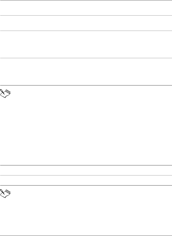
Working with tables 619
When you use the Column left command or the Column right command
from the Ta b l e Insert menu, the number of columns that are inserted
depends on how many columns you have selected. For example, if you have
selected two columns, then two columns are inserted in the table.
To delete a row or column from a table
1Select the row or column that you want to delete.
2Perform a task from the following table.
If you select a row but choose the option to delete a column, or if you select a
column but choose the option to delete a row, the whole table is deleted.
To Do the following
Insert a column to the left of the selected
column
Click Ta b l e Insert Column left.
Insert a column to the right of the selected
column
Click Ta b l e Insert Column right.
Insert multiple columns to the left of the
selected column
Click Ta b l e Insert Insert columns,
type a value in the Number of columns
box, and enable the Left of the selection
option.
Insert multiple columns to the right of the
selected column
Click Ta b l e Insert Insert columns,
type a value in the Number of columns
box, and enable the Right of the selection
option.
To Do the following
Delete a row Click Ta b l e Delete Row.
Delete a column Click Ta b l e Delete Column.
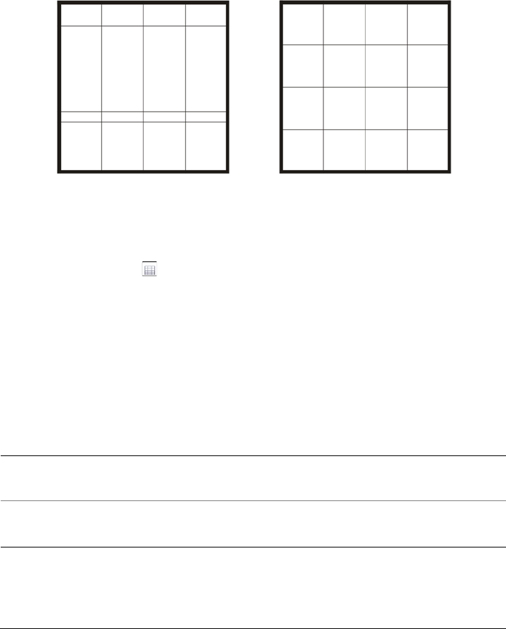
620 Corel DESIGNER X6 User Guide
Resizing table cells, rows, and columns
You can resize table cells, rows, and columns. In addition, if you previously changed the
sizes of some rows or columns, you can redistribute all rows or all columns so that they
are the same size.
If table rows are different sizes (left), you can distribute them so that they are
the same size (right).
To resize a table cell, row, or column
1Click the Ta b l e tool , and then click the table.
2Select the cell, row, or column that you want to resize.
3On the property bar, type values in the Table width and height boxes.
To distribute table rows and columns
1Select the table cells that you want to distribute.
2Perform a task from the following table.
To Do the following
Make the height of all selected rows the
same
Click Ta b l e Distribute Rows evenly.
Make the width of all selected columns the
same
Click Ta b l e Distribute Columns
evenly.
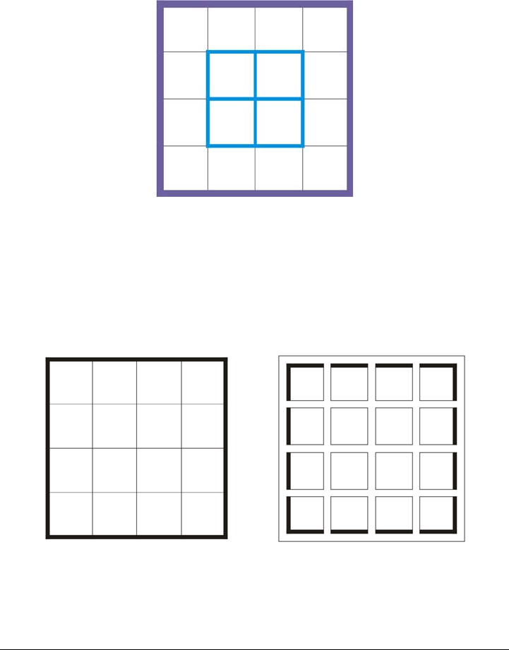
Working with tables 621
Formatting tables and cells
You can change the look of a table by modifying both table and cell borders. For
example, you can change the table border width or color.
You can modify both table and table cell borders.
In addition, you can change the table cell margins and cell border spacing. The cell
margins let you increase the space between the cell borders and the text in the cell. By
default, table cell borders overlap to form a grid. However, you can increase the cell
border spacing to move the borders away from each other. As a result, the cells do not
form a grid, but appear as individual boxes (also known as “separated borders”).
You can modify an existing table (left) by applying separated borders (right).
622 Corel DESIGNER X6 User Guide
To modify table borders and cell borders
1Select the table or table area that you want to modify.
A table area can include a cell, a group of cells, rows, columns, or the entire table.
2Click the Border selection button on the property bar, and choose the borders
that you want to modify.
3Perform a task from the following table.
To modify cell margins in tables
1Click the Ta b l e tool , and then click the table.
2Select the cells that you want to modify.
3Click Margins on the property bar.
4Type a value in the To p m a r g i n box.
By default, the value in the top margin box is applied to all margins, so that equal
margins are created.
If you want to apply different values for the margins, click the Lock margins
button to unlock the margin boxes, and type values in the To p m a r g i n , Bottom
margin, Left margin, and Right margin boxes.
5Press Enter.
To modify cell border spacing in tables
1Click the Ta b l e tool , and then click the table.
2Click Options on the property bar.
3Enable the Separated cell borders check box.
To Do the following
Modify the border thickness Choose a border width from the Outline
width list box on the property bar.
Modify the border color Click the Outline color picker on the
property bar, and then click a color on the
color palette.
Modify the border line style Click the Outline pen button on the
property bar, and set outline properties in
the Outline pen dialog box.

Working with tables 623
4Type a value in the Horizontal cell spacing box.
By default, the vertical cell spacing is equal to the horizontal cell spacing.
If you do not want equal cell spacing, click the Lock cell spacing button to unlock
the Vertical cell spacing box, and then type values in both the Horizontal cell
spacing and Vertical cell spacing boxes.
5Press Enter.
Working with text in tables
You can easily add text to table cells, and you can modify this text as you would any
other paragraph text. For example, you can change the font, add bullets, or add indents
to table text. You can change the text properties of a single table cell, or of multiple
table cells simultaneously. In addition, you can add tab stops to table cells so that text
is shifted away from the cell margins.
When you type text in a new table, you can choose to automatically adjust the size of
table cells.
To type text in a table cell
1Click the Ta b l e tool .
2Click a cell.
3Type text in the cell.
You can select text in a cell by pressing Ctrl + A.
To change the properties of text in table cells
1Using the Ta b l e tool, click a table.
2Hold down Ctrl, and click the table cells that contain text to be formatted.
3Click Te x t Te x t p r o p e r t i e s , and specify the settings you want in the Te x t
properties docker.
For more information about formatting text, see “Formatting text” on
page 483.

624 Corel DESIGNER X6 User Guide
To change the text properties for an entire row, column, or table
simultaneously, you must first select the table component or table. For more
information, see “To select a table, row, or column” on page 615.
To insert a tab stop in a table cell
•With the Ta b l e tool pointer inserted in a cell, click Te x t Insert formatting code
Ta b .
Another way to insert a tab stop is by pressing the Ta b key. To use this
method, you must set the Ta b key to insert tab stops. For information about
changing the Ta b key options, see “To change the navigational direction of the
Tab key” on page 617.
To automatically resize table cells when you type
1Click the Pick tool , and then click the table.
2Click Options on the property bar, and enable the Automatically resize cells
while typing check box.
This option can be applied to new tables that do not yet have text or other
content.
If a table already contains text, only cells to which new text is added will be
resized.
Converting tables to text
If you no longer want table text to appear in a table, you can convert the table text to
paragraph text. For more information about converting text to a table, see “To create a
table from text” on page 614.
To convert a table to text
1Click the Ta b l e tool , and then click the table.
2Click Ta b l e Convert table to text.
3In the Separate cell text with area, choose one of the following options:

Working with tables 625
• Commas — replaces each column with a comma and replaces each row with a
paragraph marker
• Ta b s — replaces each column with a tab and replaces each row with a paragraph
marker
• Paragraphs — replaces each column with a paragraph marker
• User defined — replaces each column with a specified character and replaces
each row with a paragraph marker
If you enable the User defined option, you must type a character in the User
defined box.
If you do not type a character in the User defined box, each of the table rows
is converted into a paragraph, and the table columns are ignored.
Merging and splitting tables and cells
You can change how a table is configured by merging adjacent cells, rows, and columns.
If you merge table cells, the formatting of the upper-left cell is applied to all merged
cells. Alternatively, you can unmerge cells that were previously merged.
You can change the look of a table (left) by merging adjacent table cells (right).
You can also split table cells, rows, or columns. Splitting lets you create new cells, rows,
or columns without changing the size of the table.
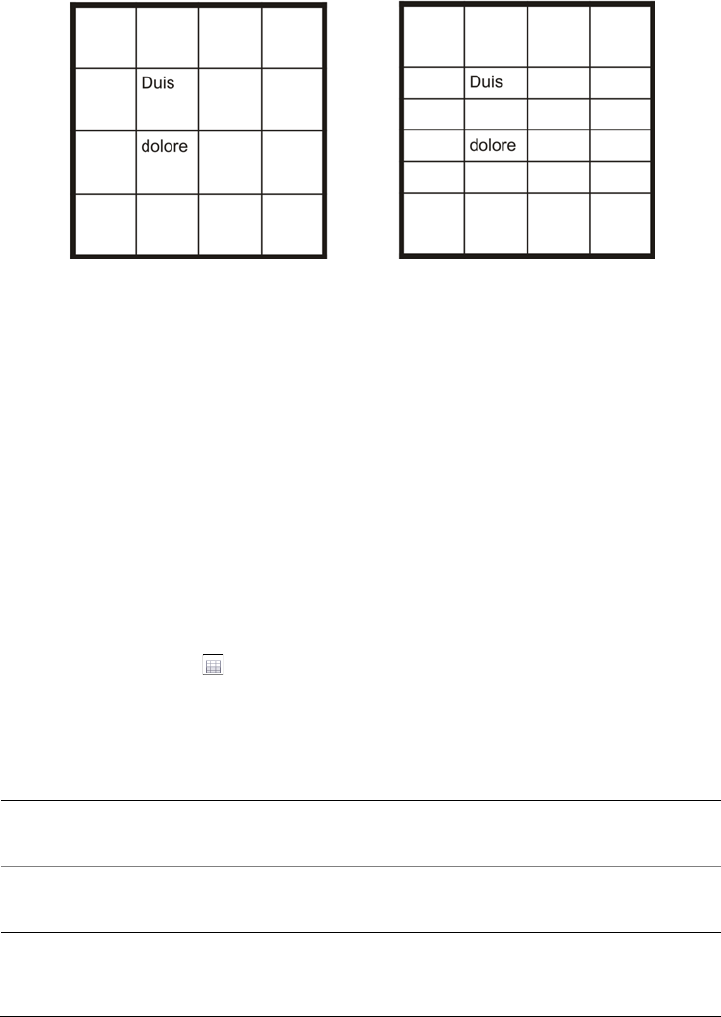
626 Corel DESIGNER X6 User Guide
You can insert additional rows in a table (left) by splitting table cells (right).
To merge table cells
1Select the cells to be merged.
The selected cells must be contiguous.
2Click Ta b l e Merge cells.
To unmerge table cells
1Select the cell that you want to unmerge.
2Click Ta b l e Unmerge cells.
To split table cells, rows, or columns
1Click the Ta b l e tool .
2Select the cell, row, or column that you want to divide.
3Perform a task from the following table.
To Do the following
Split a selection horizontally Click Ta b l e Split into rows, and type a
value in the Number of rows box.
Split a selection vertically Click Ta b l e Split into columns, and type
a value in the Number of columns box.
Working with tables 627
Manipulating tables as objects
You can manipulate tables as you would other objects.
The following table lists the various ways to manipulate a table as an object.
Adding images, graphics, and backgrounds to tables
If you want to arrange bitmap images or vector graphics in a structured layout, you can
add them to tables. You can also change the look of a table by adding a background
color.
To insert an image or a graphic in a table cell
1Copy an image or a graphic.
2Click the Ta b l e tool, and select the cell where you want to insert the image or
graphic.
3Click Edit Paste.
You can also insert a graphic or an image by holding down the right mouse
button over the image, dragging the image to a cell, releasing the right mouse
button, and then clicking Place inside cell.
You can For more information see
Resize and scale a table “Sizing and scaling objects” on page 258
Rotate a table “Rotating objects” on page 261
Mirror a table “Mirroring objects” on page 262
Lock a table “Locking objects” on page 273
Convert a table to a bitmap “Converting vector graphics to bitmaps” on
page 633
Break a table apart “To convert objects to curve objects” on
page 193

628 Corel DESIGNER X6 User Guide
To add a background color to a table
1Click the Ta b l e tool , and then click the table.
2Click the Background color picker, and then click a color on the color palette.
You can also modify the background color of specific cells, rows, or columns by
selecting the cells, clicking the Background color picker on the property bar,
and then clicking a color on the color palette.
Importing tables in a drawing
With Corel DESIGNER, you can create tables by importing content from Quattro
Pro® (.qpw) and Microsoft® Excel® (.xls) spreadsheets. You can also import tables
created in a word-processing application, such as WordPerfect or Microsoft® Word.
To import a table from Quattro Pro or Excel
1Click File Import.
2Choose the drive and folder where the spreadsheet is stored.
3Click the file to select it.
4Click Import.
The Import/Paste dialog box appears.
5From the Import tables as list box, choose Ta b l e s .
6Choose one of the following options:
• Maintain fonts and formatting — imports all fonts and formatting that are
applied to the text
• Maintain formatting only — imports all formatting that is applied to the text
• Discard fonts and formatting — ignores all fonts and formatting that are
applied to the text
To import a table from a word-processing document
1Click File Import.
2Choose the drive and folder where the text file is stored.
3Click the file.
4Click Import.

Working with tables 629
5From the Import tables as list box, choose Ta b l e s .
6Choose one of the following options:
• Maintain fonts and formatting — imports all fonts and formatting that are
applied to the text
• Maintain formatting only — imports all formatting that is applied to the text
• Discard fonts and formatting — ignores all fonts and formatting that are
applied to the text

Bitmaps 631
Bitmaps
Working with bitmaps . . . . . . . . . . . . . . . . . . . . . . . . . . . . . . . . . . . . . .633
Working with bitmap color modes . . . . . . . . . . . . . . . . . . . . . . . . . . . . .661
Tracing bitmaps and editing traced results . . . . . . . . . . . . . . . . . . . . . .671
Working with RAW camera files . . . . . . . . . . . . . . . . . . . . . . . . . . . . . . .687

Working with bitmaps 633
Working with bitmaps
You can convert a vector graphic to a bitmap. You can also import and crop bitmaps in
Corel DESIGNER.
You can also add color masks and special effects, and you can change the color and tone
of the images.
This section contains the following topics:
• Converting vector graphics to bitmaps
• Importing bitmaps
•Cropping bitmaps
• Changing the dimensions and resolution of bitmaps
• Straightening bitmaps
• Using Digimarc watermarks to identify bitmaps
• Removing dust and scratch marks from bitmaps
• Applying special effects in bitmaps
• Working with colors in bitmaps
• Using the Image Adjustment Lab
• Adjusting color and tone
• Using the Tone Curve filter
• Transforming color and tone
• Editing bitmaps with Corel PHOTO-PAINT
Converting vector graphics to bitmaps
When you convert a vector graphic to a bitmap, you can apply special effects that are
unavailable for vector graphics or objects. The process of converting a vector graphic to
a bitmap is also known as “rasterizing.”
When you convert the vector graphic, you can select the color mode of the bitmap. A
color mode determines the number and kind of colors that make up the bitmap, so the

634 Corel DESIGNER X6 User Guide
file size is also affected. For more information about color modes, see “Changing the
color mode of bitmaps” on page 661.
You can also specify settings for such controls as dithering, anti-aliasing, overprinting
black, and background transparency.
When you export a file to a bitmap file format, such as TIFF, JPEG, CPT, or PSD, the
same bitmap conversion options are available. For more information about exporting,
see “Exporting files” on page 746.
To convert a vector graphic to a bitmap
1Select an object.
2Click Bitmaps Convert to bitmap.
3Choose a resolution from the Resolution list box.
4Choose a color mode from the Color mode list box.
5Enable any of the following check boxes:
• Dithered — simulates a greater number of colors than those available. This
option is available for images that use 256 or fewer colors.
• Always overprint black — overprints black when black is the top color.
Enabling this option prevents gaps from appearing between black objects and
underlying objects when you print bitmaps.
• Anti-aliasing — smooths the edges of the bitmap
• Tr a n s p a r e n t b a c k g r o u n d — makes the background of the bitmap transparent
You can change the black threshold for the Always overprint black option.
For information about setting the black threshold, see “To set the overprint
black threshold” on page 732.
If you export a vector file to a bitmap format, such as GIF, you are prompted
to set the bitmap conversion options described in the procedure above before
you export the file.
Making the background of a bitmap transparent lets you see images or a
background otherwise obscured by the bitmap background.

Working with bitmaps 635
To convert a vector graphic to a bitmap when exporting
1Click File Export.
2Choose the folder where you want to save the file.
3Choose a bitmap file format from the Save as type list box, and type a filename in
the File name list box.
4Set the options you want, and click Export.
5In the Convert to bitmap dialog box, type values in one of the following pairs of
boxes:
• Width and Height — let you specify the image dimensions
• Width % and Height % — let you resize the image to a percentage of its
original size
6To specify the resolution, type a value in the Resolution box.
7Choose a color mode from the Color mode list box.
8Enable any of the following check boxes:
• Dithered — simulates a greater number of colors than those available. This
option is available for images that use 256 or fewer colors.
• Always overprint black — overprints black when black is the top color.
Enabling this option when you print bitmaps prevents gaps from appearing
between black objects and underlying objects.
9In the Options area, enable any of the following:
• Anti-aliasing — smooths the edges of the bitmap
• Maintain layers — preserves layers
• Tr a n s p a r e n t b a c k g r o u n d — makes the background of the bitmap transparent
You can change the black threshold for the Always overprint black option.
For information about setting the black threshold, see “To set the overprint
black threshold” on page 732.
Not all options in the Convert to bitmap dialog box are available for all
bitmap file formats.
Making the background of a bitmap transparent lets you see images or a
background otherwise obscured by the bitmap background.
636 Corel DESIGNER X6 User Guide
Importing bitmaps
You can import a bitmap into a drawing either directly or by linking it to an external
file. When you link to an external file, edits to the original file are automatically
updated in the imported file. After you import a bitmap, the status bar provides
information about its color mode, size, and resolution. For more information about
importing bitmaps, see “Importing files” on page 741. For more information about
managing externally linked bitmaps, see “Adding bookmarks and hyperlinks to
documents” on page 301.
You can also resample or crop a bitmap while importing. For more information, see “To
resample a bitmap while importing” on page 744 and “To crop a bitmap while
importing” on page 745.
Cropping bitmaps
Cropping removes unwanted areas of a bitmap. To crop a bitmap into a rectangular
shape, you can use the Crop tool. For more information, see “To crop objects” on
page 200. To crop a bitmap into an irregular shape, you can use the Shape tool and the
Crop bitmap command.
To crop a bitmap
1Click the Shape tool .
2Select a bitmap.
3Drag the corner nodes to reshape the bitmap.
If you want to add a node, double-click the node boundary (dotted line) by using
the Shape tool where you want the node to appear.
4Click Bitmaps Crop bitmap.
You cannot crop a bitmap comprised of more than one object.
You can also crop a selected bitmap after you drag the corner nodes by clicking
the Pick tool , then clicking the Crop bitmap button on the property
bar.

Working with bitmaps 637
Changing the dimensions and resolution of bitmaps
After you add a bitmap to a drawing, you can change its dimensions and resolution.
Changing dimensions
You can change the physical dimensions of bitmaps by increasing or decreasing their
height and width. When you increase the dimensions, the application inserts new pixels
between existing pixels, and their colors are based on the colors of adjacent pixels. If you
increase the dimensions of bitmaps significantly, bitmaps may appear stretched and
pixelated.
The size of the bitmap on your screen depends on the pixel height and width of the
bitmap, on the zoom level, and on your monitor settings. As a result, the size of the
bitmap may appear different on your screen and in print.
Changing bitmap resolution
You can change the resolution of a bitmap to increase or decrease its file size. Resolution
is measured by the number of dots per inch (dpi) when the bitmap is printed. The
resolution you choose depends on how the bitmap is output. Typically, bitmaps created
only for display on computer monitors are 96 or 72 dpi and bitmaps created for the Web
are 72 dpi. Bitmaps created for printing on desktop printers are generally 150 dpi, while
professionally printed bitmaps are usually 300 dpi, or higher.
Higher-resolution bitmaps contain smaller and more densely packed pixels than lower-
resolution bitmaps. Upsampling increases the resolution of a bitmap by adding more
pixels per unit of measure. Bitmap quality may be reduced because the new pixels are
interpolated based on the colors of neighboring pixels; the original pixel information is
simply spread out. You cannot use upsampling to create detail and subtle color
gradations where none existed in the original image.
Downsampling decreases the resolution of a bitmap by removing a specific number of
pixels per unit of measure. Best results are usually achieved when downsampling is done
after color and tone corrections but before sharpening.
To change the dimensions of a bitmap
1Select a bitmap.
2Click Bitmaps Resample.
3Choose a unit of measure from the list box next to the Width and Height boxes.
4Type values in any of the following boxes:

638 Corel DESIGNER X6 User Guide
• Width
• Height
If you want to minimize the jagged appearance of curves, enable the Anti-alias
check box.
If you want to maintain the file size, enable the Maintain original size check box.
When this check box is enabled, the resolution of the bitmap is automatically
adjusted as you change the image dimensions.
You can maintain the proportions of the bitmap by enabling the Maintain
aspect ratio check box and typing a value in either the Width or Height box.
You can also resample the bitmap as a percentage of its original size by typing
values in the Width % and Height % boxes.
To change the resolution of a bitmap
1Select a bitmap.
2Click Bitmaps Resample.
3In the Resolution area, type values in any of the following boxes:
• Horizontal
• Vertical
If you want to maintain the proportions of the bitmap, enable the Maintain aspect
ratio check box.
If you want to maintain the file size, enable the Maintain original size check box.
When this check box is enabled, the height and width of the bitmap are
automatically adjusted as you change the resolution.
You can also resample a selected bitmap by clicking the Resample button
on the property bar.
Enable the Anti-alias check box to minimize the jagged appearance of curves.
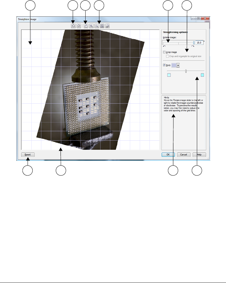
Working with bitmaps 639
Straightening bitmaps
The Straighten image dialog box lets you straighten bitmap images quickly. This
feature is useful for straightening photos that were taken or scanned at an angle.
Straighten image dialog box
You can access the Straighten image dialog box by clicking Bitmaps Straighten
image.
1. Preview window 6. Options for cropping and resampling
2. Rotation tools 7. Reset button
3. Pan tool 8. Grid
4. Zoom tools 9. Hint for active control
5. Rotate Image controls 10. Grid control
1 2 3 4 5 6
7 8 9 10

640 Corel DESIGNER X6 User Guide
The Straighten image dialog box lets you rotate an image by moving a slider, typing
a rotation angle, or using the arrow keys. You can specify a custom rotation angle from
-15 to 15 degrees.
You can use the preview window to dynamically preview the adjustments that you are
making. If you want to change the orientation of the image before straightening it, you
can start by rotating the image 90 degrees clockwise and 90 degrees counterclockwise.
A grid is displayed in the preview window to help you straighten the image. You can
make more precise adjustments by controlling the cell size of the grid. To heighten the
contrast of the grid against the colors of the image, you can change the grid’s color. You
can also hide the grid if you want to preview the final result without the gridlines. In
addition, you can zoom in and out, and pan the image in the preview window to
evaluate the results.
By default, the straightened image is cropped to the cropping area that is displayed in
the preview window. The final image has the same aspect ratio as the original image,
but it has smaller dimensions. However, you can preserve the original width and height
of the image by cropping and resampling the image.
You can also produce an image at an angle by disabling cropping and then using the
Crop tool to crop the image in the drawing window.
To straighten an image
1Select an image.
2Click Bitmaps Straighten image.
3Move the Rotate image slider, or type a value between 15 and -15 in the Rotate
image box.
4If necessary, move the Grid slider to adjust the size of the grid cells.
5To crop and straighten the image, enable the Crop image check box.
The image is cropped to preserve the aspect ratio of the original image, which
means that the final image is smaller than the original image.
If you want to preserve the width and height of the original image, enable the
Crop and resample to original size check box. The final image is resampled.

Working with bitmaps 641
Using Digimarc watermarks to identify bitmaps
A Digimarc® watermark embeds copyright details, contact information, and image
attributes in an image. A watermark makes subtle changes to the brightness of pixels
in an image. These changes cannot be readily seen; however, at high magnification, you
might notice changes in the brightness of some pixels. Digimarc watermarks aren’t
affected by normal editing, printing, and scanning.
Detecting watermarks
When you open an image in Corel DESIGNER, you can check for a watermark. If a
watermark is present, a copyright symbol appears on the title bar. You can find
information about the watermarked image by reading the embedded message and by
linking to the contact profile in the Digimarc database.
Embedding watermarks
In Corel DESIGNER, you can also embed Digimarc watermarks in images. First, you
must obtain a unique Creator ID by subscribing to Digimarc’s online service. The
Creator ID includes contact details, such as name, phone number, address, email, and
Web addresses.
Once you have a Creator ID, you can embed a watermark in an image. You can specify
the copyright year, image attributes, and the durability of a watermark. You can also
specify the target output method for an image, such as print or the Web.
Digimarc watermarks do not prevent unauthorized image use or copyright
infringement. But the watermarks do communicate copyright claims. They also provide
contact information for those who want to use or license an image.
For more information about Digimarc, see www.digimarc.com.
To detect a watermark
1Click Bitmaps Plug-ins Digimarc Read watermark.
2Click Web lo ok u p to view the Web page with contact details, or call the Digimarc
fax-back service at the listed fax number.
This feature is not supported by the 64-bit version of
CorelDRAW Technical Suite.

642 Corel DESIGNER X6 User Guide
To get a Creator ID
1Click Bitmaps Plug-ins Digimarc Embed watermark.
2Click Personalize.
3In the Personalize Creator ID dialog box, click Register, and follow the
instructions on the Digimarc Web site.
4In the Personalize Creator ID dialog box, type your Creator ID in the Creator
ID box.
To embed a watermark
1Click Bitmaps Plug-ins Digimarc Embed watermark.
2In the Copyright year(s) box, type a year or years.
3In the Image attributes area, enable the check boxes for the applicable attributes.
4Choose an option from the Ta r g e t o u t p u t list box.
5Type a value in the Watermark durability box.
Higher values increase the persistence of the watermark under common image
modifications such as dithering, cropping, compression, and scaling.
If you want to confirm the information available to viewers when they detect the
watermark, enable the Verify check box.
In the Copyright year(s) box, you cannot type a year before 1922 or after the
current year. Separate the years with commas.
In the Ta r g e t o u t p u t box, the Monitor and Web controls require a setting of
less than 200 per inch (dpi), and the Printer control requires a setting of 300
dpi or higher.
Combine all objects with the background before adding a watermark. For more
information about combining objects with the background, see “Combining
objects” on page 271.

Working with bitmaps 643
Removing dust and scratch marks from bitmaps
You can quickly improve the appearance of a bitmap by removing dust and scratch
marks. The dust and scratch filter works by eliminating the contrast between pixels that
exceed the contrast threshold you set. You can set a radius to determine how many
pixels are affected by the changes. The settings you choose depend on the size of the
blemish and the area surrounding it. For example, to remove a white scratch that is 1
or 2 pixels wide on a dark background, you can set a radius of 2 or 3 pixels and set the
contrast threshold higher than you would for a similar scratch on a light background.
To remove dust and scratch marks from a bitmap
1Click Effects Correction Dust and scratch.
2Move the following sliders:
• Radius — sets the range of pixels used to produce the effect. To retain image
detail, choose a setting as low as possible.
• Threshold — sets the amount of noise reduction. To retain image detail, choose
a setting as high as possible.
Applying special effects in bitmaps
You can apply a wide range of special effects to bitmaps, such as three-dimensional (3D)
and artistic effects.
Special effect category Description
3D Effects Lets you create the illusion of depth. Effects include
Emboss, Page Curl, and Perspective.
Art Strokes Lets you apply hand-painted techniques. Effects
include Crayon, Impressionist, Pastels, Watercolor,
and Pen & Ink.
Blur Lets you blur an image to simulate movement,
speckling, or gradual change. Effects include Gaussian
Blur, Motion Blur, and Zoom.
Camera Lets you simulate the effect produced by a diffusion
lens

644 Corel DESIGNER X6 User Guide
Adding plug-in filters to Corel DESIGNER provides additional features and effects that
you can use to edit images. You can add plug-in filters, and you can remove them when
you no longer need them.
Corel DESIGNER automatically inflates a bitmap so that a special effect covers the
entire image. You can disable automatic inflation and manually specify dimensions for
the inflated bitmap.
To apply a special effect
1Select a bitmap.
2Click Bitmaps, choose a special effect type, and click an effect.
3Adjust any special effect settings.
Color Transform Lets you create photographic illusions by using color
reduction and replacements. Effects include Halftone,
Psychedelic, and Solarize.
Contour Lets you highlight and enhance the edges of an image.
Effects include Edge Detect and Trace Contour.
Creative Lets you apply various textures and shapes to an
image. Effects include Fabric, Glass Block, Crystalize,
Vortex, and Stained Glass.
Distort Lets you distort image surfaces. Effects include Ripple,
Blocks, Swirl, and Tile.
Noise Lets you modify the graininess of an image. Effects
include Add Noise, Remove Moiré, and Remove
Noise.
Sharpen Lets you add a sharpening effect to focus and enhance
edges. Effects include Adaptive Unsharp, High Pass,
and Unsharp Mask.
Plug-ins Lets you apply effects from a third-party filter to
bitmaps in Corel DESIGNER. An installed plug-in
appears at the bottom of the Bitmaps menu.
Special effect category Description

Working with bitmaps 645
To add a plug-in filter
1Click To o l s Options.
2In the list of categories, double-click Wo rks pa c e, and click Plug-ins.
3Click Add.
4Choose a folder containing a plug-in.
To remove a plug-in filter, click a plug-in folder from the Plug-in folders list,
and click Remove.
To inflate a bitmap manually
1Select a bitmap.
2Click Bitmaps Inflate bitmap Manually inflate bitmap.
3In the Width and Height areas, do one of the following:
• In the Inflate to boxes, type the number of pixels that should make up the
dimensions of the inflated bitmap.
• In the Inflate by boxes, type the percentages by which to inflate the original
bitmap.
4To inflate the bitmap proportionally, enable the Maintain aspect ratio check box.
To automatically inflate the bitmap to cover the entire image, click Bitmaps
Inflate bitmap Auto inflate bitmap.
Working with colors in bitmaps
Corel DESIGNER lets you change colors in monochrome images, hide and show colors,
and mask colors. Monochrome bitmaps have two colors: black and white. You can
replace the black and white pixels with any color on a color palette.
You can hide and display selected colors by masking them. Hiding colors in a bitmap
lets objects or backgrounds show through the image. Hiding a color can also alter the
apparent shape of a bitmap. For example, if a bitmap shows a person on a black
background, you can hide the background so that the bitmap appears to take on the
shape of the person rather than a rectangular shape. Also, hiding colors in bitmaps can
increase the speed at which objects are rendered on the screen. You can also display

646 Corel DESIGNER X6 User Guide
certain colors in a bitmap to change the appearance of the image or to see where a
particular color has been applied. You can mask as many as 10 colors in a bitmap.
Color masking also lets you change selected colors without altering the other colors in
an image. You can also save a bitmap color mask to a file and open the file for future use.
To color a monochrome bitmap
1Select a bitmap by using the Pick tool .
2Right-click a color on the color palette to change the color of the foreground
(black) pixels.
3Click a color on the color palette to change the color of the background (white)
pixels.
To hide or display a color in a bitmap
1Select the bitmap by using the Pick tool .
2Click Bitmaps Bitmap color mask.
3Enable one of the following options:
• Hide colors
• Show colors
4Enable the check box next to the channel that you want to hide or display.
5Move the Tolerance slider to set the color tolerance for the color.
6Click the Color selector button .
7Click the color that you want to hide or display.
8Click Apply.
Higher tolerance levels target a broader range of colors around the color you
select. For example, if you select baby blue and increase the tolerance,
Corel DESIGNER hides or displays such colors as pastel blue or electric blue.
To open a bitmap color mask
1Click Bitmaps Bitmap color mask.
2Click the Open mask button .
3Choose the folder where the color mask file is stored.
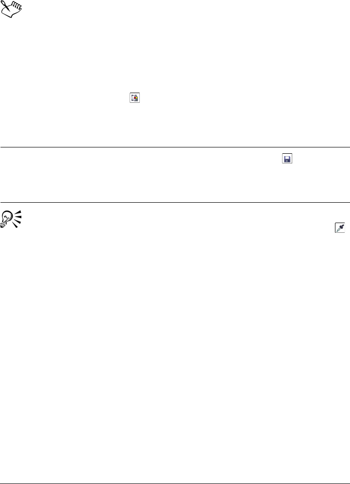
Working with bitmaps 647
4Double-click the file.
Files containing bitmap color mask have the filename extension .ini.
To change a masked color
1Click Bitmaps Bitmap color mask.
2Choose a color from the list of masked colors.
3Click the Edit color button .
4Use the controls in the Select color dialog box to edit the color.
You can also change a masked color by clicking the Color selector button ,
selecting another color from the bitmap, and clicking Apply.
Using the Image Adjustment Lab
The Image Adjustment Lab lets you correct the color and tone of most photos quickly
and easily. You can access the Image Adjustment Lab by clicking Bitmaps Image
Adjustment Lab.
You can also
Save a bitmap color mask Click the Save mask button . Choose the
folder where you want to save the current
color mask. Type a name for the file in the
File name list box. Click Save.
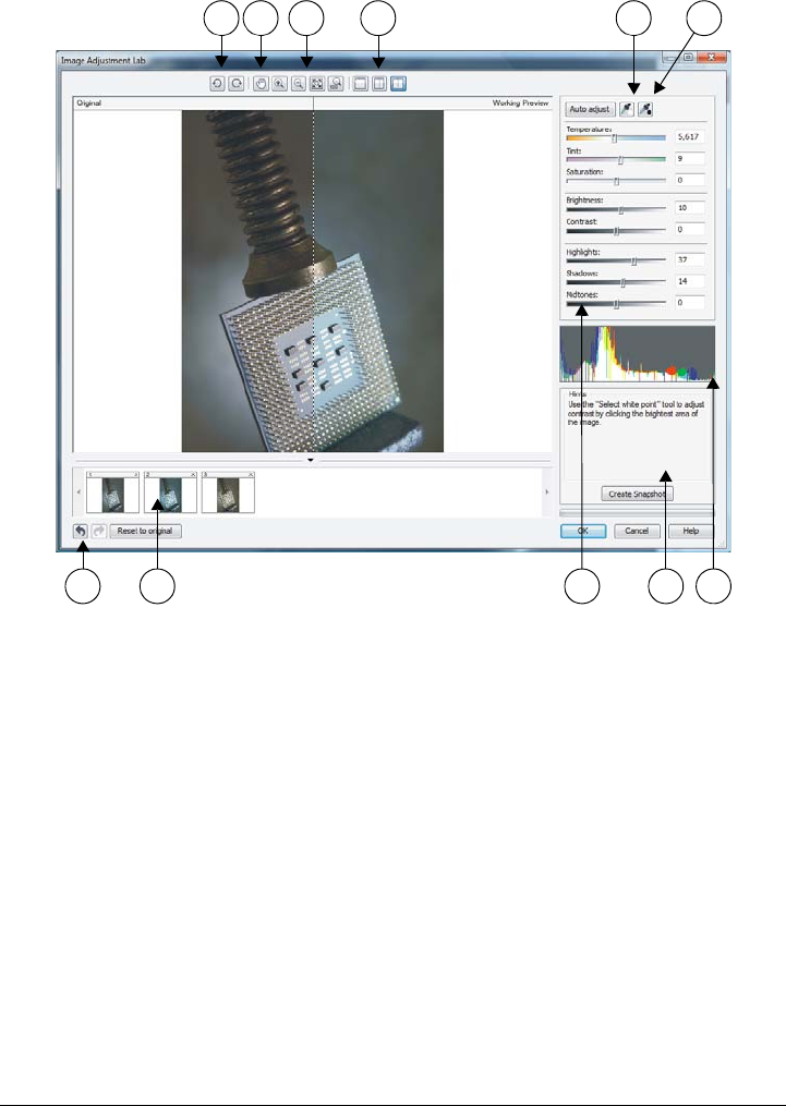
648 Corel DESIGNER X6 User Guide
The Image Adjustment Lab consists of automatic and manual controls, which are
organized in a logical order for image correction. By starting in the upper-right corner
and working your way down, you can select only the controls you need to correct the
problems specific to your image. It is best to crop or retouch any areas of the image
before beginning the color and tone corrections.
When you work in the Image Adjustment Lab, you can take advantage of the following
features:
•Create snapshot — You can capture the corrected version of an image in a
“snapshot” at any time. Thumbnails of the snapshots appear in a window below the
1. Rotation tools 5. Select white point 9. Sliders
2. Pan tool 6. Select black point 10. Hint for current tool
3. Zoom tools 7. Undo, Redo, and Reset 11. Histogram
4. Preview Modes 8. Snapshots
1 2 3 4 5 6
7 8 9 10 11

Working with bitmaps 649
image. Snapshots make it easy to compare different corrected versions of the image
so you can choose the best one.
•Undo, Redo, and Reset to original — Image correction can be a trial-and-error
process, so the ability to undo and redo corrections is important. The Reset to
original command lets you clear all corrections so that you can start again.
Using automatic controls
You can begin by using the automatic correction controls:
•Auto adjust — automatically corrects the contrast and color in an image by
detecting the lightest and darkest areas and adjusting the tonal range for each color
channel. In some cases, this control may be all you need to improve an image. In
other cases, you can undo the changes and proceed with more precise controls.
•Select white point tool — automatically adjusts the contrast in an image
according to the white point that you set. For example, you can brighten an image
that is too dark by using the Select white point tool.
•Select black point tool — automatically adjusts the contrast in an image
according to the black point that you set. For example, you can darken an image
that is too light by using the Select black point tool.
Using color correction controls
After using the automatic controls, you can correct color casts in your image. Color casts
are typically caused by the lighting conditions when a photo is taken, and they can be
influenced by the processor in your digital camera or scanner.
•Te m p e r a t u r e slider — lets you correct color casts by “warming” or “cooling” the
color in an image to compensate for the lighting conditions at the time the photo
was taken. For example, to correct a yellow color cast caused by taking a photo
indoors in dim incandescent lighting, you can move the slider toward the blue end
to increase the temperature values (based on degrees Kelvin). Lower values
correspond to low lighting conditions, such as candlelight or light from an
incandescent light bulb; these conditions cause an orange cast. Higher values
correspond to intense lighting conditions, such as sunlight; these conditions cause a
blue cast.
•Tint slider — lets you correct color casts by adjusting the green or magenta in an
image. You can add green by moving the slider to the right; you can add magenta
by moving the slider to the left. Moving the Tint slider after using the
Te m p e r a t u r e slider lets you fine-tune an image.
•Saturation slider — lets you adjust the vividness of colors. For example, by moving
the slider to the right, you can increase the vividness of a blue sky in an image. By
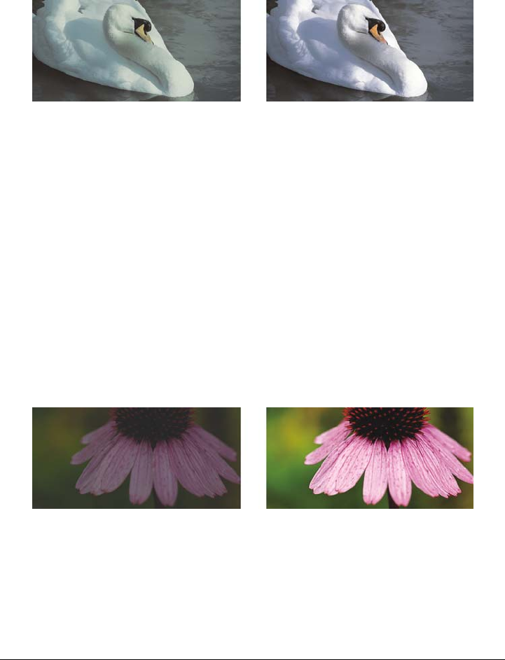
650 Corel DESIGNER X6 User Guide
moving the slider to the left, you can reduce the vividness of colors. You can create
a black-and-white photo effect by moving the slider all the way to the left, so that
all color in the image is removed.
Correction of a color cast. The image on the right is the corrected version.
Adjusting brightness and contrast across an entire image
You can brighten, darken, or improve the contrast in an entire image by using the
following controls:
•Brightness slider — lets you brighten or darken an entire image. This control can
correct exposure problems caused by too much light (overexposure) or too little
light (underexposure) at the time the photo was taken. If you want to lighten or
darken specific areas of an image, you can use the Highlights, Shadows, and
Midtones sliders. Adjustment made by the Brightness slider is nonlinear, so the
current white point and black point values are not affected.
•Contrast slider — increases or decreases the difference in tone between the dark
and light areas of an image. Moving the slider to the right makes the light areas
lighter and the dark areas darker. For example, if the image has a dull, gray tone,
you can sharpen the detail by increasing the contrast.
Adjusting the brightness and contrast of an image can reveal more image
detail.
Adjusting highlights, shadows, and midtones
You can brighten or darken specific areas of an image. In many cases, the position or
strength of the lighting at the time a photo is taken causes some areas to appear too
dark and other areas to appear too light.
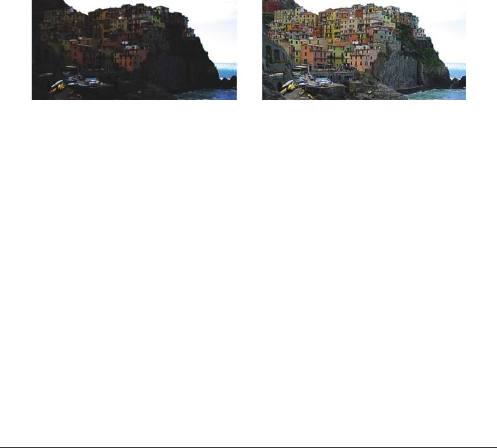
Working with bitmaps 651
•Highlights slider — lets you adjust brightness in the lightest areas of an image.
For example, if you take a photo with a flash, and the flash washes out the
foreground subjects, you can move the Highlights slider to the left to darken the
washed-out areas of the image. You can use the Highlights slider in conjunction
with the Shadows and Midtones sliders to balance the lighting.
•Shadows slider — lets you adjust the brightness in the darkest areas of an image.
For example, a bright light behind a photo subject (backlighting) at the time a
photo is taken can cause the subject to appear in shadow. You can correct the photo
by moving the Shadow slider to the right to lighten the dark areas and reveal more
detail. You can use the Shadows slider in conjunction with the Highlights and
Midtones sliders to balance the lighting.
•Midtones slider — lets you adjust the brightness of the midrange tones in an
image. After adjusting the highlights and shadows, you can use the Midtones
slider to fine-tune the image.
The Highlights and Shadows sliders can lighten or darken specific areas of
an image.
Using the histogram
The histogram lets you view the tonal range of an image to evaluate and adjust the color
and tone. For example, a histogram can help you detect hidden detail in a photo that is
too dark because of underexposure (a photo taken with insufficient light).
The histogram plots the brightness values of the pixels in an image on a scale of 0 (dark)
to 255 (light). The left part of the histogram represents the shadows, the middle part
represents the midtones, and the right part represents the highlights. The height of the
spikes indicates how many pixels are at each brightness level. For example, a higher
number of pixels on the left side of the histogram indicates the presence of image detail
in the dark areas of the image.
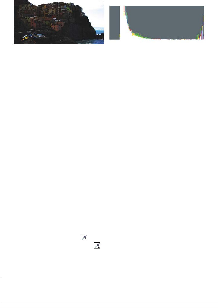
652 Corel DESIGNER X6 User Guide
The photo on the left is underexposed. Right: The histogram indicates a large
amount of image detail in the dark areas of the photo.
Viewing images in the Image Adjustment Lab
The tools in the Image Adjustment Lab let you view images in various ways, so that you
can evaluate the color and tone adjustments you make. For example, you can rotate
images, pan to a new area, zoom in or out, and choose how to display the corrected
image in the preview window.
Using other adjustment filters
Although the Image Adjustment Lab lets you correct the color and tone of most images,
a specialized adjustment filter is sometimes required. Using the powerful adjustment
filters in the application, you can make precise adjustments to images. For example, you
can adjust images by using a tone curve. For more information about adjustment filters,
see “Adjusting color and tone” on page 654.
To correct color and tone in the Image Adjustment Lab
1Click Bitmaps Image Adjustment Lab.
2Click Auto adjust.
Auto adjust automatically adjusts color and contrast by setting the white point
and black point for an image.
If you want to control the white point and black point setting more precisely, click
the Select white point tool , and click the lightest area of your image. Then
click the Select black point tool , and click the darkest area of your image.
3Perform one or more tasks from the following table.
To Do the following
Correct color in the image Adjust the Te m p e r a t u r e slider to warm or
cool the colors, and then fine-tune the color
correction by adjusting the Tint slider.
Working with bitmaps 653
The Image Adjustment Lab is not available for CMYK images. For CMYK
images, you can access the Auto adjust filter and other adjustment filters from
the Effects menu.
You can capture the current version of your image by clicking the Create
snapshot button. Thumbnails of the snapshots appear in a window below your
image. Each snapshot is numbered sequentially and can be deleted by clicking
the Close button in the upper-right corner of the snapshot title bar.
You can undo or redo the last correction you made by clicking the Undo
button or the Redo button . To undo all corrections, click the Reset to
original button.
To view images in the Image Adjustment Lab
1Click Bitmaps Image Adjustment Lab.
2Perform a task from the following table.
Make colors more vivid or less vivid Move the Saturation slider to the right to
increase the amount of color in the image;
move the slider to the left to decrease the
amount of color in the image.
Brighten or darken an image Move the Brightness slider to the right to
lighten the image; move the slider to the left
to darken the image.
Improve image sharpness by adjusting tone Move the Contrast slider to the right to
make the light areas lighter and the dark
areas darker.
Brighten or darken specific areas Move the Highlights slider to brighten or
darken the lightest areas of the image. Then,
move the Shadows slider to lighten or
darken the darkest areas of the image.
Finally, move the Midtones slider to fine-
tune the midrange tones in the image.
To Do the following
654 Corel DESIGNER X6 User Guide
Adjusting color and tone
Corel DESIGNER lets you adjust the color and tone of bitmaps. For example, you can
replace colors and adjust the brightness, lightness, and intensity of colors.
By adjusting color and tone, you can restore detail lost in shadows or highlights, remove
color casts, correct underexposure or overexposure, and generally improve the quality
of the bitmaps. You can also correct color and tone quickly by using the Image
Adjustment Lab. For more information, see “Using the Image Adjustment Lab” on
page 647.
You can adjust the color and tone of bitmaps automatically by using the Auto Adjust
command or by using the following filters.
To Do the following
Rotate the image Click the Rotate left button or the
Rotate right button .
Pan to another area of an image Using the Pan tool , drag the image until
the area you want to see is visible.
Zoom in and out Using the Zoom in tool or the Zoom
out tool , click in the preview window.
Fit an image in the preview window Click the Zoom to fit button.
Display an image at its actual size Click the 100% button.
View the corrected image in a single preview
window
Click the Full preview button .
View the corrected image in one window and
the original image in another window
Click the Before and after full preview
button .
View the image in one window with a
divider between the original and corrected
versions
Click the Before and after split preview
button . Move your pointer over the
dashed divider line, and drag to move the
divider to another area of the image.

Working with bitmaps 655
Effect Description
Contrast enhancement Lets you adjust the tone, color, and contrast
of a bitmap while preserving shadow and
highlight detail. An interactive histogram
lets you shift or compress brightness values
to printable limits. The histogram can also
be adjusted by sampling values from the
bitmap.
Local equalization Lets you enhance contrast near edges to
reveal detail in both light and dark regions.
You can set the height and width around the
region to accentuate contrast.
Sample/Target balance Lets you adjust color values in a bitmap with
sample colors taken from the image. You can
choose sample colors from the dark,
midtone, and light ranges of an image and
apply target colors to each of the sample
colors.
Tone curve Lets you perform color corrections precisely,
by controlling individual pixel values. By
changing pixel brightness values, you can
make changes to shadows, midtones, and
highlights. For more information, see “Using
the Tone Curve filter” on page 657.
Brightness/contrast/intensity Lets you adjust the brightness of all colors
and the difference between light and dark
areas
Color balance Lets you add cyan or red, magenta or green,
and yellow or blue to selected tones in a
bitmap
Gamma Lets you accentuate detail in low contrast
areas without affecting shadows or
highlights

656 Corel DESIGNER X6 User Guide
To adjust color and tone automatically
1Select a bitmap.
2Click Bitmaps Auto adjust.
Hue/saturation/lightness Lets you adjust the color channels in a
bitmap and change the position of colors in
the spectrum. This effect allows you to
change colors and their richness, as well as
the percentage of white in an image.
Selective color Lets you change color by changing the
percentage of spectrum CMYK process
colors from the red, yellow, green, cyan,
blue, and magenta color spectrums in a
bitmap. For example, decreasing the
percentage of magenta in the reds spectrum
results in a color shift toward yellow.
Replace colors Lets you replace one bitmap color with
another color. A color mask is created to
define the color to be replaced. Depending
on the range you set, you can replace one
color or shift an entire bitmap from one color
range to another. You can set the hue,
saturation, and lightness for the new color.
Desaturate Lets you reduce the saturation of each color
in a bitmap to zero, remove the hue
component, and convert each color to its
grayscale equivalent. This creates a grayscale
black-and-white photo effect without
changing the color model.
Channel mixer Lets you mix color channels to balance the
colors of a bitmap. For example, if a bitmap
has too much red, you can adjust the red
channel in an RGB bitmap to improve image
quality.
Effect Description
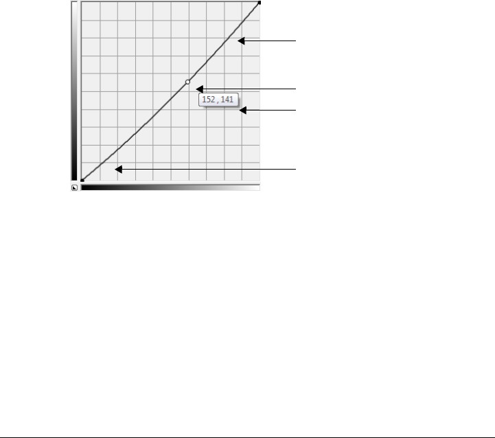
Working with bitmaps 657
To adjust color and tone by using an adjustment filter
1Select a bitmap.
2Click Effects Adjust, and click an adjustment filter.
3Specify any settings you want.
Using the Tone Curve filter
The To n e c u r v e filter lets you perform color and tonal corrections by adjusting either
individual color channels or the composite channel (all channels combined). Individual
pixel values are plotted along a tone curve that appears in a graph and represents the
balance between shadows (bottom of graph), midtones (middle of graph), and
highlights (top of graph). The x-axis of the graph represents the tonal values of the
original image; the y-axis of the graph represents the adjusted tonal values.
The tone curve shows the balance between the shadows, midtones, and
highlights of an image. The original (x) and adjusted (y) pixel values are
displayed side by side when you drag the tone curve. This example shows a
small adjustment to the tonal range, in which pixel values of 152 are replaced
with pixel values of 141.
You can fix problem areas by adding nodes to the tone curve and dragging the curve. If
you want to adjust specific areas in an image, you can use the Eyedropper tool and
select the areas in the image window. You can then drag the nodes that appear on the
tone curve to achieve the effect you want.
Highlights
Shadows
Midtones
Dynamic preview of
original and adjusted
values

658 Corel DESIGNER X6 User Guide
Original image (left); the image with adjusted tonal range (right)
The histogram lets you view the adjusted tonal range and evaluate the results. For more
information about histograms, see “Using the histogram” on page 651.
To fine-tune your adjustments, you can choose a curve style from the Style list box. For
example, you can redraw the curve by using freehand lines or straight line segments.
You can adjust the color and tone of an image by applying a preset. To access a preset,
click the Open button to the right of the Presets box. You can also save tone settings
as presets to use with other images.
In addition, you can equalize the tonal range of an image by clicking Auto balance
tone. To specify the outlying pixels (clipped pixels) at each end of the tonal range, you
can click Settings and type values in the Auto-adjust range dialog box.
Transforming color and tone
You can transform the color and tone of an image to produce a special effect. For
example, you can create an image that looks like a photographic negative or flatten the
appearance of an image. To transform the color and tone of images, you can use the
following effects:
•Deinterlace — lets you remove lines from scanned or interlaced images
•Invert — lets you reverse the colors of an image. Inverting an image creates the
appearance of a photographic negative.
•Posterize — lets you reduce the number of tonal values in an image. Posterize
removes gradations and creates larger areas of flat color.
To transform color and tone
1Select a bitmap.

Working with bitmaps 659
2Click Effects Tr a n s f o r m , and click any of the following:
• Deinterlace
• Invert
• Posterize
Editing bitmaps with Corel PHOTO-PAINT
You can access Corel PHOTO-PAINT, a complete image-editing application, from
within Corel DESIGNER. When you finish editing a bitmap, you can quickly resume
your work with Corel DESIGNER.
To send a bitmap to Corel PHOTO-PAINT, you can click the Edit bitmap button on
the property bar, or you can use the Edit bitmap command from the Bitmaps menu.
You can also enable an option that lets you access Corel PHOTO-PAINT by double-
clicking a bitmap.
You can copy selected objects from Corel PHOTO-PAINT and then paste them into
your drawing. The selected objects are pasted as a group of bitmaps.
For more information about editing images with Corel PHOTO-PAINT, click Help
Help topics from the Corel PHOTO-PAINT menu bar.
To edit a bitmap with Corel PHOTO-PAINT
1Using the Pick tool , select the bitmap that you want to edit.
2On the property bar, click Edit bitmap to start Corel PHOTO-PAINT.
The selected bitmap is displayed in the image window of Corel PHOTO-PAINT.
3Edit the bitmap.
4On the standard toolbar, click Finish editing to quit Corel PHOTO-PAINT.
The edited bitmap appears on the drawing page of Corel DESIGNER.
You can also use this procedure to edit groups of bitmaps.
Corel PHOTO-PAINT opens the group of bitmaps as separate objects. If the
bitmaps in the group have different color modes, you are prompted to change
the color mode of all bitmaps in the group to the color mode of the bottom-
most bitmap.
You can also open Corel PHOTO-PAINT by clicking Bitmaps Edit
bitmaps.

660 Corel DESIGNER X6 User Guide
To access Corel PHOTO-PAINT by double-clicking a bitmap
1Click To o l s Options.
2In the Wo rk s pa ce list of categories, click Edit.
3On the Edit page, enable the Double-click to edit bitmaps in PHOTO-PAINT
check box.
Enabling this check box lets you access Corel PHOTO-PAINT by double-clicking
the bitmap in Corel DESIGNER.

Working with bitmap color modes 661
Working with bitmap color modes
Changing an image to another color mode, such as RGB, CMYK, or Grayscale,
changes a bitmap’s color structure.
This section contains the following topics:
• Changing the color mode of bitmaps
• Changing bitmaps to black-and-white images
• Changing bitmaps to duotones
• Changing bitmaps to the paletted color mode
Changing the color mode of bitmaps
The colors of the images that you work with in Corel DESIGNER are based on color
modes. Color modes define the color characteristics of images and are described by their
component colors. The CMYK color mode is composed of cyan, magenta, yellow, and
black values; the RGB color mode is composed of red, green, and blue values.
Although you may not be able to see the difference between an image in the CMYK
color mode and an image in the RGB color mode on screen, the images are quite
different. For the same image dimensions, an RGB image has a smaller file size than a
CMYK image, and the RGB color space, or gamut, can display more colors. Therefore,
images intended for the Web or desktop printers, which require accurate color fidelity,
are generally in RGB mode. Where accurate print reproduction is needed, such as on a
commercial printing press, images are generally created in CMYK mode. Paletted color
images attempt to preserve color fidelity while reducing the file size, making them ideal
for on-screen uses.
Each time you convert an image, you may lose color information. For this reason, you
should save an edited image before you change it to a different color mode. For more
information about color modes, see“Working with color” on page 333.
Corel DESIGNER supports the following color modes:
• Black and White (1-bit)

662 Corel DESIGNER X6 User Guide
•Duotone (8-bit)
• Grayscale (8-bit)
• Paletted (8-bit)
• RGB Color (24-bit)
• Lab Color (24-bit)
• CMYK Color (32-bit)
To change the color mode of a bitmap
1Click a bitmap.
2Click Bitmaps Mode, and click a color mode.
The current mode of the selected bitmap is not available in the menu.
Changing bitmaps to black-and-white images
You can change any image to a black-and-white image. In addition to conversion
settings such as threshold, screen type, and intensity, there are seven conversion options
that affect how the converted images will look.
Conversion
Line art Produces a high-contrast, black-and-white
image. Colors with a grayscale value lower
than the threshold value that you set change
to black, while colors with a grayscale value
higher than the threshold value change to
white.
Ordered Organizes the gray levels into repeating
geometric patterns of black and white pixels.
Solid colors are emphasized and image edges
are hard. This option is best suited for
uniform colors.

Working with bitmap color modes 663
To change a bitmap to a black-and-white image
1Click a bitmap.
2Click Bitmaps Mode Black-and-white (1-bit).
3Choose an option from the Conversion method list box.
4Move the Intensity slider.
If you want to view different parts of the image, you can drag the image in the
Preview window.
The Intensity slider is not available for the Halftone conversion option.
Changing bitmaps to duotones
To convert an image to a duotone, you change a bitmap to the grayscale color mode and
enhance it using one to four additional colors, giving the image greater tonal depth.
Halftone Creates different shades of gray by varying
the pattern of black and white pixels in an
image. You can choose the screen type, angle
for the halftone, lines per unit, and the unit
of measure.
Cardinality-Distribution Creates a textured look by applying a
calculation and distributing the result to the
screen.
Jarvis Applies the Jarvis algorithm to the screen.
This form of error diffusion is suitable for
photographic images.
Stucki Applies the Stucki algorithm to the screen.
This form of error diffusion is suitable for
photographic images.
Floyd-Steinberg Applies the Floyd-Steinberg algorithm to
the screen. This form of error diffusion is
suitable for photographic images.
Conversion

664 Corel DESIGNER X6 User Guide
The following four variations of the color mode correspond to the number of additional
inks:
•Monotone — a grayscale image colored with a single tone
•Duotone — a grayscale image colored with two tones. In most cases, one is black
and the other is colored.
•Tr i t o n e — a grayscale image colored with three tones. In most cases, one is black
and the other two are colored.
•Quadtone — a grayscale image colored with four tones. In most cases, one is black
and the other three are colored.
Adjusting tone curves
When you change an image to a duotone, a tone curve grid that represents the dynamic
tone curves that are used throughout the conversion is displayed. The horizontal plane
(x-axis) displays the 256 possible shades of gray in a grayscale image (0 is black; 255 is
white). The vertical plane (y-axis) indicates the intensity of a color (from 0 to 100
percent) that is applied to the corresponding grayscale values. For example, a grayscale
pixel with a color value of 25 is printed with a 25-percent tint of the color. By adjusting
the tone curves, you can control the color and intensity of the tone that is added to an
image.
Saving and loading inks
You can save an adjusted duotone tone curve and ink settings and then load them for
use with other bitmaps.
Specifying how overprint colors display
When you change an image to a duotone, you can specify the colors to overprint when
you print an image. Overprint colors are used to preserve color integrity when inks
overlap. When you display the image, each color is applied on the screen in sequence,
creating a layered effect.
You can view all instances in which the colors you choose for the duotone conversion
overlap. Associated with each instance is the color that is produced by the overlap. You
can also choose new overprint colors to see how they overlap.
Duotones hold their color ink information when you save to EPS, PDF,
Corel DESIGNER (DES), and Corel PHOTO-PAINT (CPT) file formats. Other file
formats don’t support duotone images.
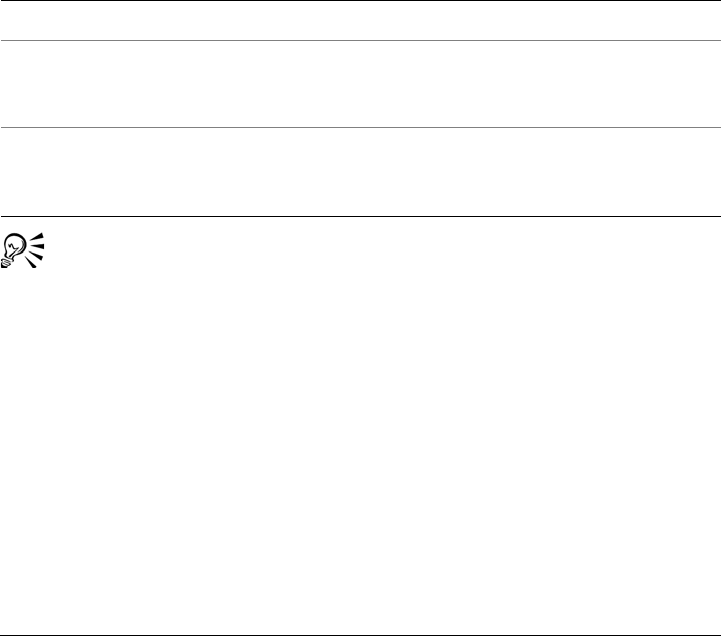
Working with bitmap color modes 665
To change an image to a duotone
1Click a bitmap.
2Click Bitmaps Mode Duotone (8-bit).
3Click the Curves tab.
4Choose a duotone type from the Ty p e list box.
5Double-click an ink color in the Ty p e window.
6In the Select color dialog box, choose a color, and click OK.
If you want to adjust the color’s tone curve, click the ink tone curve on the grid to
add a node, and drag the node to adjust the percentage of color at that point on the
curve.
7Repeat steps 5 and 6 for each ink color you want to use.
You can load preset ink colors by clicking Load, locating the file in which the
ink settings are stored, and double-clicking the filename.
Changing bitmaps to the paletted color mode
The paletted color mode, also called indexed color mode, is sometimes used for images
on the World Wide Web. When you convert an image to the paletted color mode, a
fixed color value is assigned to each pixel. These values are stored in a compact color
table, or palette, containing up to 256 colors. As a result, the paletted color mode image
contains less data than a 24-bit color mode image, and it has a smaller file size.
Conversion to paletted color mode works best on images that have a limited range of
colors.
You can also
Display all the ink tone curves on the grid. Enable the Show all check box.
Save the ink settings Click Save. Choose the disk and folder where
you want to save the file, and type a filename
in the File name box.
Specify how overprint colors display Click the Overprint tab, and enable the Use
overprint check box. Double-click the color
you want to edit, and choose a new color.

666 Corel DESIGNER X6 User Guide
Choosing, editing, and saving a color palette
When you change an image to the paletted color mode, you can use a predefined
palette, or you can customize a color palette by replacing individual colors.
Saving conversion settings
After you choose a color palette and set the dithering and range sensitivity for changing
an image to the paletted color mode, you can save the settings as a conversion preset
that you can use with other images. You can add as many conversion presets as you
want.
The color palette you use is called the processed color palette. It can be saved for use
with other images.
For more information about the predefined color palettes available for the paletted color
mode, see “Palette types” on page 667. For more information about creating and
opening custom color palettes, see “Creating and editing custom color palettes” on
page 350.
Dithering
Changing images to the paletted color mode lets you use dithering to enhance color
information. Dithering places pixels with specific colors or values relative to other pixels
of a specific color. The relationship of one colored pixel to another creates the
appearance of additional colors that do not exist in the color palette.
You can use two types of dithering: ordered dithering and error diffusion. Ordered
dithering approximates color blends using fixed dot patterns; as a result, solid colors are
emphasized and edges appear harder. Error diffusion scatters pixels irregularly, making
edges and colors softer. Jarvis, Stucki, and Floyd-Steinberg are conversion options that
provide error diffusion.
The Ordered dithering option applies more quickly than the error diffusion options
(Jarvis, Stucki, and Floyd-Steinberg) but is less accurate.
Specifying a range-sensitivity color
You can change an image to the paletted color mode and specify a focus color and a
range sensitivity for the focus color, so that the focus color and colors that fall within
the range settings are included in the processed color palette. You can also specify how
much emphasis to place on the range sensitivity. Because the palette has a maximum of
256 colors, emphasizing a focus color reduces the number of colors that fall outside the
range sensitivity.

Working with bitmap color modes 667
Palette types
The table below outlines available palette types.
Palette type Description
Uniform Provides a range of 256 colors with equal
parts of red, green, and blue
Standard VGA Provides the Standard VGA 16-color palette
Adaptive Provides colors original to the image and
preserves the individual colors (the entire
color spectrum) in the image
Optimized Creates a color palette based on the highest
percentage of colors in the image. You can
also specify a range-sensitivity color for the
color palette. This is the most common color
palette for photographic images.
Black Body Contains colors that are based on
temperature. For example, black may
represent cold temperatures, while red,
orange, yellow, and white may represent hot
temperatures.
Grayscale Provides 256 shades of gray, ranging from
black to white
System Provides the predefined palette of colors used
by the operating system
Web-safe Provides a predefined palette of 216 non-
dithered colors that will display the same on
most browsers. This palette is not
recommended for use with photographs and
only benefits users with older computers.
Custom Lets you add colors to create a customized
color palette
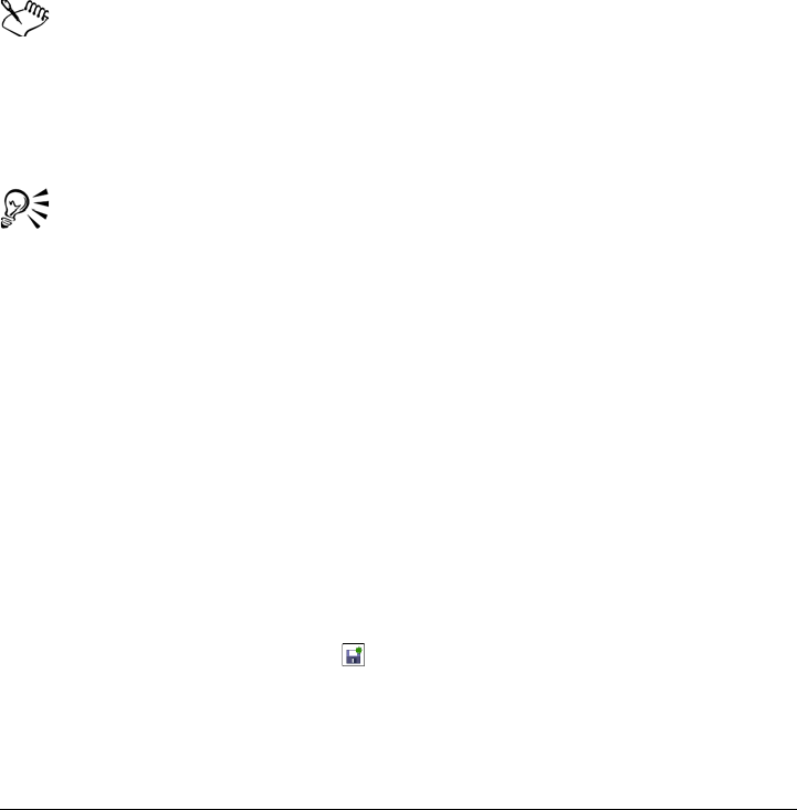
668 Corel DESIGNER X6 User Guide
To change an image to the paletted color mode
1Click a bitmap.
2Click Bitmaps Mode Paletted (8-bit).
3Click the Options tab.
4Choose a color palette type from the Palette list box.
5Choose an option from the Dithering list box.
6Move the Dithering intensity slider.
If you want to save the conversion settings as a preset, click the Add preset button,
and type a name in the Save preset box.
You can achieve better color fidelity by choosing the palette you want to use
when you change an image to a paletted bitmap or when you export a GIF or
PNG. For example, the standard color palette provides more colors than
necessary for an image with a limited range of colors, but you can choose an
optimized palette to ensure that color representation is accurate.
You can choose a custom color palette by clicking Open, locating the color
palette file you want, and double-clicking the filename.
You can load preset conversion settings by choosing a preset from the Preset
list box.
To create a custom processed color palette
1Click a bitmap.
2Click Bitmaps Mode Paletted (8-bit).
3Click the Processed palette tab.
4Click a color, and click the Edit button.
5In the Color table, specify the color you want, and click Edit color.
6Edit the color, and click OK.
7Click the Save palette as button to save the new palette.
8Choose the disk and folder where you want to store the color palette.
9Ty p e a n a m e i n t h e Name box, and click Save.

Working with bitmap color modes 669
To change a bitmap by setting range sensitivity
1Click a bitmap.
2Click Bitmaps Mode Paletted (8-bit).
3Click the Options tab.
4Choose Optimized from the Palette list box.
5Enable the Color range sensitivity to check box.
6Click the Eyedropper tool , and click a color in the image.
7Click the Range sensitivity tab.
8Move the range sensitivity sliders.
If you want to preview the color palette, click the Processed palette tab.

Tracing bitmaps and editing traced results 671
Tracing bitmaps and editing traced
results
Corel DESIGNER lets you trace bitmaps to convert them to fully editable and scalable
vector graphics. You can trace artwork, photos, scanned sketches, or logos and then
easily integrate them into your designs.
For information about the difference between vector graphics and bitmaps, see
“Understanding vector graphics and bitmaps” on page 53.
This section contains the following topics:
• Tracing bitmaps
•PowerTRACE controls
• Previewing traced results
• Fine-tuning traced results
• Adjusting colors in traced results
• Setting default tracing options
• Tips for tracing bitmaps and editing traced results
Tracing bitmaps
You can trace a bitmap in one step by using the Quick Trace command. Alternatively,
you can choose a suitable tracing method and preset style and then use the
PowerTRACE controls to preview and adjust the traced results. Corel DESIGNER
offers two methods for tracing bitmaps: Centerline Trace and Outline Trace.
Choosing a tracing method
The Centerline Trace method uses unfilled closed and open curves (strokes) and is
suitable for tracing technical illustrations, maps, line drawings, and signatures. This
method is also referred to as “stroke tracing.”
672 Corel DESIGNER X6 User Guide
The Centerline Trace method was used to convert the original bitmap (top) into
a vector graphic (bottom).
The Outline Trace method uses curve objects with no outlines and is suitable for tracing
clipart, logos, and photo images. The Outline Trace method is also referred to as “fill”
or “contour tracing.”
Choosing a preset style
A preset style is a collection of settings that are appropriate for the specific type of
bitmap you want to trace (for example, line art or a high-quality photo image). Each
tracing method comes with specific preset styles.
The Centerline Trace method offers two preset styles: one for technical illustrations and
another for line drawings.
The Outline Trace method offers the following preset styles that are suitable for line art,
logos, clipart, and photo images.
Technical illustration Line drawing
Tracing bitmaps and editing traced results 673
Adjusting traced results
You can adjust the traced results by using the controls in the PowerTRACE dialog box.
For more information, see “Fine-tuning traced results” on page 677 and “Adjusting
colors in traced results” on page 680.
To trace a bitmap by using Quick Trace
1Select a bitmap.
2Click Bitmaps Quick Trace.
Line art Logo
Detailed logo Clipart
Low-quality image
High-quality image

674 Corel DESIGNER X6 User Guide
You can also trace a bitmap in one step by clicking the Trace bitmap flyout
button on the property bar and clicking Quick Trace.
You can change the settings that are used by Quick Trace. For more
information, see “Setting default tracing options” on page 684.
To trace a bitmap by using the Centerline Trace method
1Select a bitmap.
2Click Bitmaps Centerline trace, and click one of the following:
• Technical illustration — to trace black-and-white illustrations with thin, faint
lines
• Line drawing — to trace black-and-white sketches with thick, prominent lines
If necessary, adjust the traced results by using the controls of the PowerTRACE
dialog box.
You can also access PowerTRACE from the Trace bitmap flyout button on the
property bar.
To trace a bitmap by using the Outline Trace method
1Select a bitmap.
2Click Bitmaps Outline trace, and click one of the following:
• Line art — lets you trace black-and-white sketches and illustrations
• Logo — lets you trace simple logos with little detail and few colors
• Detailed logo — lets you trace logos that contain fine detail and many colors
• Clipart — lets you trace ready-to-use graphics that vary according to their
amount of detail and number of colors
• Low quality image— lets you trace photos that lack fine detail (or that contain
fine detail that you want to ignore)
• High quality image — lets you trace high-quality, highly detailed photos
If necessary, adjust the traced results by using the controls of the PowerTRACE
dialog box.
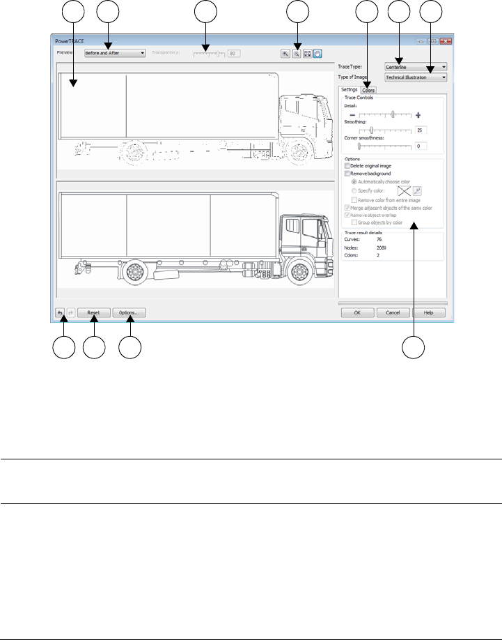
Tracing bitmaps and editing traced results 675
PowerTRACE controls
The PowerTRACE dialog box contains controls that help you preview and edit traced
results.
Circled numbers correspond to the numbers in the following table, which
describes the main controls of PowerTRACE.
Control Description
1. Preview window Lets you preview the traced result and
compare it to the source bitmap
1 2 3 4 5 6 7
111098

676 Corel DESIGNER X6 User Guide
2. Preview list box Lets you choose one of the following
previewing options:
•Before and after — lets you display both
the source bitmap and the traced result
•Large preview — lets you preview a
traced result in a single-pane preview
window
•Wireframe overlay — lets you display a
wireframe (outline) view of the traced
result on top of the source bitmap
3. Transparency slider Controls visibility of the source bitmap
below the wireframe when the Wireframe
overlay option is selected
4. Zooming and panning tools Let you zoom in and out of an image
displayed in the preview window, pan an
image displayed at a zoom level higher than
100%, and fit an image to the preview
window.
5. Colors page Contains controls for modifying the colors of
the traced results. For more information, see
“Adjusting colors in traced results” on
page 680.
6. Tr a c e t y p e list box Lets you change the tracing method
7. Type of image list box Lets you choose a suitable preset style for the
image to be traced. The available preset
styles change, depending on the tracing
method you choose.
8. Undo and Redo buttons Let you undo and redo the last action you
performed
9. Reset button Lets you restore the first settings used to
trace the source bitmap
Control Description

Tracing bitmaps and editing traced results 677
Previewing traced results
By default, PowerTRACE displays both the source bitmap and the traced result. You
can also preview a traced result in a single-pane preview window, or you can display a
wireframe (outline) view of the traced graphic on top of the source bitmap.
You can zoom in and out to get a better view of the graphic, and you can pan to view
areas that fall outside the preview window.
To preview traced results
• In PowerTRACE, choose one of the following options from the Preview list box:
• Before and after — displays both the source bitmap and the traced result
• Large preview — displays a preview of the traced result in PowerTRACE
• Wireframe overlay — displays a wireframe (outline) preview of the traced result
on top of the original bitmap. To control the visibility of the original bitmap
underneath the wireframe, move the Transparency slider.
Fine-tuning traced results
PowerTRACE lets you perform the following adjustments to fine-tune your trace
results.
10. Options button Lets you access the PowerTRACE options
page in the Options dialog box to set
default tracing options. For more
information, see “Setting default tracing
options” on page 684.
11. Settings page Contains controls for adjusting the traced
results. The Tr a c e d r e s u l t d e t a i l s area on
the Settings page lets you view the number
of objects, nodes, and colors in the traced
result while you are making adjustments.
For more information about adjusting traced
results, see “Fine-tuning traced results” on
page 677.
Control Description
678 Corel DESIGNER X6 User Guide
Adjusting detail and smoothing
You can adjust the amount of detail in the traced result and smooth curved lines. When
you adjust detail, you change the number of objects in the traced result. If you used the
Outline Trace method to trace the bitmap, adjusting the traced result also changes the
number of colors. Smoothing changes the number of nodes in the traced result. You can
also control the appearance of corners in the traced result by setting the threshold for
corner smoothness.
Left to right: Original image (left); outline tracing with a low detail value
(middle); outline tracing with a high detail value (right)
Completing a trace
By default, the source bitmap is preserved after being traced, and objects in the traced
result are automatically grouped. You can have the source bitmap automatically deleted
after the trace is complete.
Removing and preserving the background
You can choose to remove or preserve the background in the traced result. With the
Outline Trace method, you can also specify the background color to be removed. If the
background color around the edges is removed but some background color still shows
through some areas of the image, you can remove the background from the entire
image.
Setting other Outline Trace options
By default, object areas that are hidden from view by overlapping objects are removed
from the traced result. You can choose to keep the underlying object areas. This feature
is useful for traced results that will be output to vinyl cutters and screen printers.

Tracing bitmaps and editing traced results 679
To reduce the number of objects in the traced result, you can combine adjacent objects
of the same color. You can also group objects of the same color so that you can
manipulate them more easily in Corel DESIGNER.
Undoing and redoing actions
You can adjust the settings in PowerTRACE and retrace a bitmap as many times as
necessary until you are satisfied with the result. If you make a mistake, you can undo or
redo an action, or you can revert to the first traced result.
To fine-tune traced results
1Select a bitmap.
2Do one of the following:
• Click Bitmaps Centerline trace, and click a command.
• Click Bitmaps Outline trace, and click a command.
3On the Settings page, move any of the following sliders:
• Detail — lets you control the amount of original detail that is preserved in the
traced result. Higher values maintain more detail and result in a greater number
of objects and colors; lower values discard some detail and result in fewer objects.
• Smoothing — lets you smooth curved lines and control the number of nodes in
the traced result. Higher values result in fewer nodes and produce curves that do
not closely follow the lines in the source bitmap. Lower values result in more
nodes and produce more accurate trace results.
• Corner smoothness — This slider works in conjunction with the Smoothing
slider and lets you control the appearance of corners. Lower values maintain the
appearance of corners; higher values smooth corners.
You can also
Change the tracing method Choose a method from the Tr a c e t y p e list
box.
Change the preset style Choose a preset style from the Type of
image list box.
Keep the source bitmap after a trace In the Options area, disable the Delete
original image check box.
Discard or preserve the background in the
traced result
Enable or disable the Remove background
check box.
680 Corel DESIGNER X6 User Guide
You can also access PowerTRACE from the Trace bitmap flyout button on the
property bar.
Adjusting colors in traced results
When the source bitmap is traced, the application generates a color palette for the
traced result. The color palette uses the color mode of the source bitmap (for example,
RGB or CMYK). The number of colors on the color palette is determined by the
number of colors in the source bitmap and the selected preset style.
Specify the background color you want to
remove (Outline Trace)
Enable the Specify color option, click the
Eyedropper tool , and click a color in the
preview window. To specify an additional
background color to remove, hold down
Shift, and click a color in the preview
window.
The last specified color is displayed next to
the Eyedropper tool.
Remove a background color from the entire
image (Outline Trace)
Enable the Remove color from entire
image check box.
Keep object areas that are hidden by
overlapping objects (Outline Trace)
Disable the Remove object overlap check
box.
Group objects by color (Outline Trace) Enable the Group objects by color check
box.
This check box is available only when the
Remove object overlap check box is
disabled.
Merge adjacent objects that have the same
color (Outline Trace)
Enable the Merge adjacent objects of the
same color check box.
Undo or redo an action Click the Undo or Redo button.
Revert to the first traced result Click Reset.
You can also

Tracing bitmaps and editing traced results 681
You can change the color mode of the traced result, and you can reduce the number of
colors in the traced result.
Left to right: Original image (left); traced graphic that contains 152 colors
(middle); traced graphic that contains 5 colors (right)
Sorting colors
To edit the color palette more easily, you can sort colors by similarity or frequency.
Sorting by similarity arranges the colors based on their hue and lightness. Colors of
similar hue and lightness appear close to each other on the color palette. Sorting by
frequency arranges the colors based on how much they are used in the traced results.
The colors that are used most appear at the top of the color palette.
Selecting colors
You can select a color by clicking it on the color palette of the traced result or by clicking
the color in the preview window. You can also select multiple colors.
Editing, merging, and deleting colors
When editing a color, you can choose a color from a color model that is different from
that of other colors on the palette. For example, if you are editing a color in an RGB
traced result, you can change the color to a spot color, creating a mixed color palette.
This feature is useful when you are preparing the traced result for commercial printing.
With the Outline Trace method, you can also merge and delete colors.
By default, when two or more colors are merged, their color values are averaged to
produce a new color. The merged colors are replaced by the new color. However, you
can change the default setting to replace the colors to be merged with the first color that
682 Corel DESIGNER X6 User Guide
you selected. For information on how to change the default setting, see “Setting default
tracing options” on page 684.
When you delete a color from the color palette, the deleted color is replaced by the next
color on the color palette.
Using and creating color palettes
If you want the traced result to contain only colors from a specific color palette, you can
open that color palette in PowerTRACE. The colors of the traced result are replaced by
their closest match on the color palette.
After you edit the color palette of the traced graphic, you can save it to create a custom
color palette for later use.
To adjust the colors of a traced result
1Select a bitmap.
2Do one of the following:
• Click Bitmaps Centerline trace, and click a command.
• Click Bitmaps Outline trace, and click a command.
3Click the Colors tab, and perform any of the following tasks.
To Do the following
Change the color mode Choose a color mode from the Color mode
list box.
Reduce the number of colors in a traced
result (Outline Trace)
Type a value in the Number of colors box,
and click outside the box.
Select a color Do one of the following:
•Click a color on the color palette. The
selected color swatch button appears
pressed.
•Click the Eyedropper tool , and click a
color in the preview window. A marquee
appears around the selected color. To select
an additional color, hold down Shift, and
click a color in the preview window. To
deselect a color, hold down Ctrl, and click
a color.

Tracing bitmaps and editing traced results 683
The number of colors cannot be reduced, and colors cannot be merged, when
you use the Centerline Trace method.
Select a range of adjacent colors Hold down Shift, and click the first and last
color swatch in the range you are selecting
on the color palette.
Select multiple nonadjacent colors Hold down Ctrl, and click the nonadjacent
color swatches on the color palette.
Edit a color Select the color you want to edit, click Edit,
and modify settings in the Select color
dialog box.
Merge colors (Outline Trace) Select the colors that you want to merge,
and click Merge.
If you want to specify how to merge the
colors, click Options to access the Options
dialog box, and enable an option in the
Merge colors area.
Delete a color from a traced result (Outline
Tr a c e )
Select a color, and click the Delete color
button .
The deleted color is replaced by the next
color on the color palette.
Use a custom color palette Click the Open color palette button ,
find the folder where the palette is stored,
and click a filename.
Color palettes have a .cpl filename
extension.
Each color of the traced graphic is mapped
to a similar color on the custom palette.
Create a custom color palette from the
edited color palette of a traced result
Click the Save color palette button . In
the Save palette as dialog box, type a name
in the File name box.
To Do the following

684 Corel DESIGNER X6 User Guide
To increase the number of colors in a traced result, you need to change the
preset style or increase the amount of detail. For information about how to
change the preset style and the amount of detail, see “To fine-tune traced
results” on page 679.
Setting default tracing options
You can enable any of the following tracing options.
•Quick Trace method — You can change the default Quick Trace settings to any
preset style, or to the most recently used settings.
•Performance — This option determines how source bitmaps between 1 and 5
megapixels in size are handled, and how the quality of the traced results is affected.
The performance of PowerTRACE depends on the size and color depth of the
source bitmaps as well as on the available system memory. High-quality traced
results require high-quality source bitmaps, which are often quite large. The larger
the source bitmap, the more resources are required. Bitmaps that are too large need
to be downsampled before tracing, which may decrease the image quality. To trace
large bitmaps without sacrificing quality, you can set PowerTRACE to trace images
as large as 5 megapixels (provided RAM is sufficient). To achieve maximum
performance, you can set PowerTRACE to prompt you to downsample bitmaps
larger that 1 megapixel.
•Merge colors — You can choose whether to merge colors in a traced result by
averaging their values or by replacing the colors to be merged with the first color
you select.
To set default tracing options
1Click To o l s Options.
2In the Wo rk s pa ce list of categories, click PowerTRACE.
3Perform any of the following tasks.
To Do the following
Choose a Quick Trace method From the Quick Trace method list box,
choose a preset style or the most recently
used settings.
Tracing bitmaps and editing traced results 685
You can also access the PowerTRACE page in the Options dialog box by
clicking Options in PowerTRACE.
Tips for tracing bitmaps and editing traced results
The following tips can help you achieve high-quality trace results.
• Use high-quality source bitmaps. If dithering or JPEG compression was used in the
source bitmap, the bitmap may contain additional noise. For best traced results,
remove the noise before tracing the bitmap.
• For best results when you use the Centerline Trace method, convert the bitmap to
the black-and-white color mode before tracing. Note that in this case you cannot
adjust detail.
• When tracing technical illustrations and sketches with faint lines, you can improve
the results by applying the Find edges special effect to the source bitmap. To do
this, click Bitmaps Contour Find edges.
• For outline tracing, reduce the color depth of the bitmap by changing the color
mode, and then adjust the color and contrast.
• You can adjust the traced results at any time, including during a trace, by changing
the PowerTRACE settings.
• To trace a specific area in a bitmap, use the Shape tool to define the area before
clicking Bitmaps Tr a c e b i t m a p .
Determine performance level and quality of
a traced result
Move the Performance slider to the left to
increase performance, or to the right to
increase the quality of the traced results. The
lowest value prompts you to downsample all
bitmaps that exceed 1 megapixel. The
highest value prompts you to downsample
all bitmaps that exceed 5 megapixels.
Choose how to merge colors in a traced
result
In the Merge colors area, enable an option.
The Average merging colors option
replaces the colors to be merged with a color
of their average value. The Merge to first
color selected option replaces the colors to
be merged with the first selected color.
To Do the following

686 Corel DESIGNER X6 User Guide
• If important detail has been removed from the traced results, you can disable the
Remove background check box on the Settings page of PowerTRACE. You can
also try enabling the Specify color option on the Settings page and sampling the
color you want to specify as a background color.
• If background color is removed around the edges but remains within image areas,
enable the Remove from entire image check box.
• If too many colors or details are lost, move the Detail slider on the Settings page.
• To preserve detail in bitmaps that have fine details, thin lines, and no anti-aliasing
applied, choose Line art from the Ty p e o f i m a g e list box on the Settings page.

Working with RAW camera files 687
Working with RAW camera files
You can import and process RAW camera files in Corel DESIGNER.
This section contains the following topics:
•Using RAW camera files
• Bringing RAW camera files into Corel DESIGNER
• Adjusting the color and tone of RAW camera files
• Sharpening and reducing noise in RAW camera files
• Previewing RAW camera files and obtaining image information
Using RAW camera files
RAW camera files contain picture data that is captured by the image censor of a digital
camera. These files are called RAW because, unlike JPEG and TIFF files, they contain
minimal in-camera processing and need to be edited and prepared for printing in an
image-editing application.
With RAW camera files, you can control the processing of image data, rather than
having the camera make automatic color adjustments and conversions. You can adjust
the white balance, tonal range, contrast, color saturation, and sharpness of a RAW
image without any loss of image quality. In addition, you can reprocess RAW images at
any time to achieve the results you want. In this sense, RAW camera files can be
compared to an exposed but undeveloped film.
To take advantage of RAW camera files, you need to set your camera to save files to its
own RAW file format. Corel DESIGNER lets you import RAW camera files from
supported camera models.To find a list of supported cameras, visit the Corel Knowledge
Base.

688 Corel DESIGNER X6 User Guide
Bringing RAW camera files into Corel DESIGNER
When you open single or multiple RAW camera files in Corel DESIGNER, they are first
displayed in the Camera RAW Lab. You can use the controls in the Camera RAW Lab
to adjust the color and tone of the RAW camera images.If you are satisfied with the
adjustments of a file, you can apply the same adjustments to the remaining files.
After processing RAW camera files, you can edit them further by using the tools and
effects available in Corel DESIGNER. Then, you can save the RAW camera files as TIFF
or JPEG files, or you can save them to any other file format supported by
Corel DESIGNER.
Note that RAW camera files cannot be saved to a RAW camera file format in
Corel DESIGNER. Any changes made to the RAW camera files in the Camera RAW
Lab are lost unless you save the files to a supported file format.
Processing RAW camera files
The Camera RAW Lab includes controls that are organized in a logical order for color
correction and other adjustments of RAW camera images. It is recommended that you
start from the top of the Color page and work your way down. Once you finish
correcting the color and tone of your image, you can sharpen it and remove noise by
using the controls on the Detail page. For information about the settings on the Color
page, see “Adjusting the color and tone of RAW camera files” on page 691. For
information about the settings on the Detail page, see “Sharpening and reducing noise
in RAW camera files” on page 694.
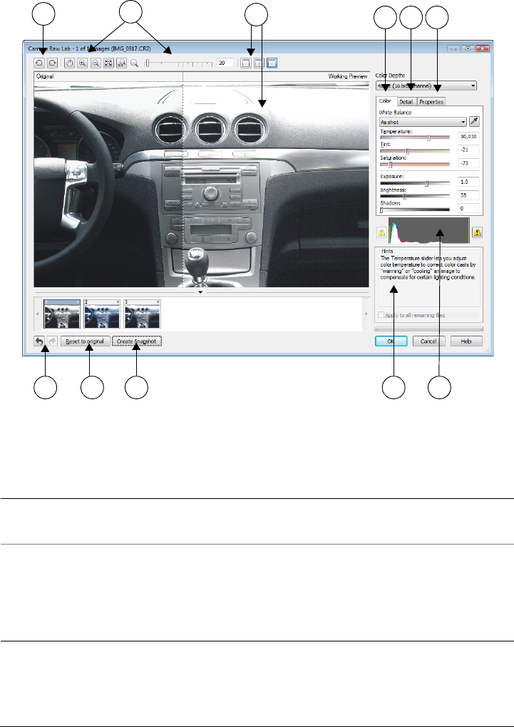
Working with RAW camera files 689
Camera RAW Lab: circled numbers correspond to the numbers in the following
table, which describes the main components of the lab.
Component Description
1. Rotation tools Let you rotate the image 90 degrees
clockwise and counterclockwise
2. Zooming and panning tools Let you zoom in and out of an image
displayed in the preview window, pan an
image displayed at a zoom level higher than
100%, and fit an image to the preview
window
123456
7 8 9 10 11

690 Corel DESIGNER X6 User Guide
To bring a RAW camera file into Corel DESIGNER
1Click File Import.
2Select the RAW camera file or files that you want to import, and click Import.
3In the Camera RAW Lab, adjust the color and tone of the RAW camera image. If
necessary, you can also sharpen the image and reduce the amount of noise.
3. Preview modes and Preview window Let you preview the adjustments made to a
RAW camera image in a single or split
window. To compare the original and the
adjusted image, you can display them side
by side.
4. Color page Contains controls that let you adjust the
color and tone of RAW camera images to
remove color casts and reveal hidden detail
5. Detail page Contains controls that let you remove noise
from RAW camera images
6. Properties page Contains controls that let you view
information about a RAW camera image,
such as size, color mode, and camera settings
7. Undo and Redo buttons Let you undo and redo the last action you
performed
8. Reset to original button Lets you clear all corrections so that you can
start with the original RAW camera image
9. Create snapshot Lets you capture the corrected version of an
image in a “snapshot” at any time.
Thumbnails of the snapshots appear in a
window below the image.
10. Hints area Displays information about the active
control
11. Histogram Lets you preview the tonal range of the
image.
Component Description

Working with RAW camera files 691
If you selected multiple RAW camera files and want to apply the same adjustments
to all of them, enable the Apply to all remaining files check box.
You can rotate the image by clicking the Rotate left button or Rotate
right button .
Adjusting the color and tone of RAW camera files
You can adjust the color and tone of an image by using the following settings.
Color depth
Color depth refers to the number of colors an image can contain. One of the advantages
of using RAW camera files is that they can contain more colors than photos saved as
JPEG or TIFF files. This greater number of colors makes it easier to reproduce colors
accurately, reveal detail in shadows, and adjust brightness levels.
The Camera RAW Lab lets you process the RAW camera files as 48-bit or 24-bit
images. 48-bit images offer more accurate color representation and prevent loss of
image quality during retouching. Note that some of the special effects available in
Corel DESIGNER cannot be applied to 48-bit images.
White balance
White balance is the process of removing unnatural color casts from images so that
image colors appear as they do in real life. White balance takes into consideration the
lighting conditions in which a photo was taken and sets the color balance to produce
realistic image colors.
By default, when a RAW camera file is brought into Corel DESIGNER, it reflects the
camera setting for white balance. This setting appears as the preset As shot in the
White balance list box. If you are not satisfied with this setting, you can have the white
balance adjusted automatically by choosing the preset Auto. You can also apply any of
the following presets: Daylight, Cloudy, Shade, Tu n g s t e n , Fluorescent, or Flash.
These presets let you simulate different lighting conditions.
In addition, you can use the Eyedropper tool to automatically adjust the contrast in an
image according to the white or gray point that you sample in the preview window.
If the White balance options do not produce the results you want, you can use the
following controls to remove color casts:

692 Corel DESIGNER X6 User Guide
•Te m p e r a t u r e slider — lets you correct color casts by adjusting the color
temperature of an image to compensate for the lighting conditions at the time the
photo was taken. For example, to correct a yellow color cast caused by taking a
photo indoors in dim incandescent lighting, you can move the slider to the left.
Conversely, to correct a blue color cast caused by intense lighting conditions, you
can move the slider to the right.
•Tint slider — lets you correct color casts by adjusting the green or magenta in an
image. You can add green by moving the slider to the right; you can add magenta
by moving the slider to the left. Moving the Tint slider after using the
Te m p e r a t u r e slider lets you fine-tune an image.
Tonal adjustments
You can use the following controls to adjust the tone of RAW camera files.
•Saturation slider — lets you adjust the vividness of colors. For example, by moving
the slider to the right, you can increase the vividness of a blue sky in an image. By
moving the slider to the left, you can reduce the vividness of colors.
•Exposure slider — lets you compensate for the lighting conditions at the time the
photo was taken. Exposure is the amount of light allowed to fall on the image
sensor of a digital camera. High exposure values result in areas that are completely
white (no detail); low values result in increased shadows. Exposure values (EV)
range from -3.0 to + 3.0.
•Brightness slider — lets you brighten or darken an entire image. If you want to
darken only the darkest areas of an image, you must use the Shadow slider.
•Shadow slider — lets you adjust the brightness in the darkest areas of an image
without affecting the lighter areas. For example, a bright light behind a photo
subject (backlighting) at the time a photo is taken can cause the subject to appear
in shadow. You can correct the photo by moving the Shadow slider to the right to
lighten dark areas and reveal more detail.
Using the histogram
While you are making adjustments, you can view the tonal range of the image on the
histogram to check for any clipping of shadow or highlight areas. Clipping is the
shifting of image pixels to white (highlight clipping) or black (shadow clipping).
Clipped highlight areas appear completely white and contain no detail; clipped shadow
areas appear completely black and contain no detail.
The button on the left side of the histogram displays a warning if the image contains
shadow clipping. The button on the right side of the histogram displays a warning if
Working with RAW camera files 693
the image contains highlight clipping. You can also choose to apply shading to the
clipped areas in the preview window.
To adjust the color and tone of a RAW camera file
1Click File Import.
2Select the RAW camera file or files that you want to import, and click Import.
3From the Color depth list box, choose one of the following options:
• 48-bit (16 bits/channel)
• 24-bit (8 bits/channel)
4To remove a color cast, select the Auto option from the White balance list box.
If you are not satisfied with the results, you can set the white point more precisely
by using the Eyedropper tool to sample a white or gray color in your image.
5Perform one or more tasks from the following table.
To Do the following
Simulate different lighting conditions Select an option from the White balance list
box.
Correct color in the image Adjust the Te m p e r a t u r e slider, and then
fine-tune the color correction by adjusting
the Tint slider.
Make colors more vivid or less vivid Move the Saturation slider to the right to
increase the amount of color in the image or
to the left to decrease the amount of color in
the image.
Adjust exposure Move the Exposure slider to the left to
compensate for high-exposure camera
settings or to the right to compensate for
low-exposure camera settings.
Brighten or darken an image Move the Brightness slider to the right to
lighten the image or to the left to darken the
image.
Adjust the brightness in the darker areas of
an image without changing the lighter areas
Move the Shadow slider.
Show clipped shadow areas Click the button to the left of the histogram.

694 Corel DESIGNER X6 User Guide
You can capture the current version of your image by clicking Create
snapshot. Thumbnails of the snapshots appear in a window below your image.
Each snapshot is numbered sequentially and can be deleted by clicking the
close button in the upper right corner of the snapshot title bar.
To change a color or tone setting one increment at a time, you can click in the
box to the right of a slider, and press the Up or Down arrow keys.
You can undo or redo the last correction you made by clicking Undo or Redo.
To undo all corrections, click Reset to original.
Sharpening and reducing noise in RAW camera files
You can sharpen RAW camera files to enhance image edges.
RAW camera files may contain luminous (grayscale) and color (chroma) noise that is
especially obvious in the darker areas of an image. Luminous noise appears as a “white
snow” effect; color noise appears as random pixels of different colors scattered against
image areas. You can reduce noise in RAW camera files to improve image quality.
To sharpen a RAW camera file
1Click File Import.
2Select the RAW camera file or files that you want to import, and click Import.
3In the Camera RAW Lab, click the Detail tab.
4Move the Sharpness slider to enhance the edges in an image.
To reduce noise in a RAW camera file
1Click File Import.
2Select the RAW camera file or files that you want to import, and click Import.
3Click the Detail tab.
4Move any of the following sliders to the right:
Show clipped highlight areas Click the button to the right of the
histogram.
To Do the following

Working with RAW camera files 695
• Luminance noise — to reduce the amount of luminance noise
• Color noise — to reduce the amount of color noise. Note that higher settings
may decrease the color accuracy of an image.
Adjusting both the Luminance noise and Color noise settings produces
better results.
Previewing RAW camera files and obtaining image information
By previewing RAW camera files in various ways, you can evaluate the color and tone
adjustments you make. For example, you can rotate images, pan to a new area, zoom in
or out, and choose how to display the processed image in the preview window.
You can obtain information about the color mode, size, and resolution of a RAW camera
file. In addition, you can obtain information about the camera and camera settings used
when the photo was taken.
To preview a RAW camera file
1Click File Import.
2Select the RAW camera file or files that you want to import, and click Import.
3In the Camera RAW Lab, perform a task from the following table.
To Do the following
Pan to another area of an image Using the Pan tool , drag the image until
the area that you want to see is visible.
Zoom in and out Using the Zoom in tool or Zoom out
tool , click in the preview window.
You can also zoom in and out by dragging
the Zoom slider.
Fit an image in the preview window Click the Zoom to fit button.
Display an image at its actual size Click the 100% button.
View the corrected image in a single preview
window
Click the Full preview button .

696 Corel DESIGNER X6 User Guide
To obtain information about a RAW camera file
1Click File Import.
2Select the RAW camera file or files that you want to import, and click Import.
3In the Camera RAW Lab, click the Properties tab, and view any of the properties
that are available for the selected RAW camera file, such as color space, camera
manufacturer and model, focal length, exposure time, and ISO speed ratings.
View the corrected image in one window and
the original image in another window
Click the Before and after full preview
button .
View the image in one window with a
divider between the original and corrected
versions
Click the Before and after split preview
button . Move your pointer over the
dashed divider line, and drag to move the
divider to another area of the image.
To Do the following


Printing basics 699
Printing basics
Corel DESIGNER provides extensive options for printing your work.
This section includes the following topics:
• Printing your work
• Laying out print jobs
• Previewing print jobs
• Applying print styles
• Fine-tuning print jobs
• Printing colors accurately
• Printing to a PostScript printer
•Using print merge
• Viewing preflight summaries
Printing your work
Using Corel DESIGNER, you can print one or more copies of the same drawing. You
can also specify the page type and the page range that you want to print.
Before printing a drawing, you can specify printer properties, including paper size and
device options. For example, you can specify printer features such as duplexing stapling.
To set printer properties
1Click File Print.
2Click the General tab.
3In the Destination area, choose a printer from the Printer list box.
4Click Preferences.
5Set any properties in the dialog box.
700 Corel DESIGNER X6 User Guide
To print your work
1Click File Print.
2Click the General tab.
3In the Destination area, choose a printer from the Printer list box.
4In the Destination area, choose a page size and orientation option from the Page
list box.
5In the Copies area, type a value in the Number of copies box.
If you want the copies collated, enable the Collate check box.
6In the Print range area, enable one of the following options:
• Current document — prints the active drawing
• Current page — prints the active page
• Pages — prints the pages that you specify
• Documents — prints the documents that you specify
• Selection — prints the objects that you have selected
If you enable the Pages option, you can choose to print a range of pages, only even
pages, only odd pages, or both even and odd pages.
You must select objects before printing a selection.
Certain printers support the automatic matching of page size and orientation.
To enable this option, you need to modify the driver compatibility settings for
the printer by clicking To o l s Options. In the list of categories, double-click
Global, double-click Printing, click Driver compatibility, and enable the
Printer can match document page sizes check box. In the Print dialog box,
you can then choose Match orientation and size from the Page list box.
You can also
Automatically match the printer orientation
to the document orientation
In the Destination area, choose Match
orientation from the Page list box.
Apply the printer’s default page size In the Destination area, choose Use printer
default from the Page list box.

Printing basics 701
Laying out print jobs
You can lay out a print job by specifying the size, position, and scale. Tiling a print job
prints portions of each page on separate sheets of paper that you can assemble into one
sheet. You would, for example, tile a print job that is larger than your printer paper.
To specify the size and position of a print job
1Click File Print.
2Click the Layout tab.
3In the Image position and size area, enable one of the following options:
• As in document — maintains the image size as it is in the document
• Fit to page — sizes and positions the print job to fit to a printed page
• Reposition images to — lets you reposition the print job by choosing a position
from the list box
Enabling the Reposition images to option lets you specify size, position, and
scale in the corresponding boxes.
You can also choose an imposition layout, such as 2 x 2 (4-up) or 2 x 3 (6-
up), from the Imposition layout list box. For more information, see
“Working with imposition layouts” on page 720.
To tile a print job
1Click File Print.
2Click the Layout tab.
3In the Image position and size area, enable the Print tiled pages check box.
4Type values in the following boxes:
• Tile overlap — lets you specify the amount by which to overlap tiles
• % of page width — lets you specify the percentage of the page width the tiles
will occupy
You can include tiling alignment marks by enabling the Tiling marks check
box.
702 Corel DESIGNER X6 User Guide
Previewing print jobs
You can preview your work to show how the position and size of the print job will appear
on paper. For a detailed view, you can zoom in on an area. You can view how the
individual color separations will appear when printed.
Before printing your work, you can view a summary of issues for a print job to find
potential printing problems. For example, you can check the current print job for print
errors, possible print problems, and suggestions for resolving issues.
To preview a print job
•Click File Print preview.
To close the print preview, click File Close print preview.
You can quickly preview a print job in the Print dialog box by clicking File
Print and clicking the Mini preview button .
To magnify the preview page
1Click File Print preview.
2Click View Zoom.
3Enable the Percent option, and type a value in the box.
You can also magnify the preview page by choosing a preset zoom level.
You can also zoom in on a portion of the print preview by clicking the Zoom
tool in the toolbox and marquee selecting an area.
To preview color separations
1Click File Print preview.
2On the property bar, click the Enable color separations button .
You can preview the composite by clicking View Preview separations
Composite.
You can view individual color separations by clicking the tabs at the bottom of
the application window.

Printing basics 703
To view a summary of issues for a print job
1Click File Print.
2Click the Preflight tab.
If there are no print job issues, the tab name displays as No issues. If there are
issues, the tab name displays the number of issues that were found.
If you want to exclude certain issues from the preflight check, click Settings,
double-click Printing, and disable any check boxes that correspond to issues you
want overlooked.
You can save settings by clicking the Add preflight settings button and
typing a name in the Save preflight style box.
Applying print styles
A print style is a set of saved printing options. Each print style is a separate file. This
lets you move a print style from one computer to another, back up a print style, and
keep document-specific styles in the same directory as the document file.
You can select an existing print style, create a new print style, or edit a print style and
save the changes. You can also delete print styles.
To choose a print style
1Click File Print.
2Click the General tab.
3Choose one of the following from the Print style list box:
• Corel DESIGNER defaults
• Browse
To create a print style
1Click File Print.
2Click the General tab.
3Set any printing options.
4Click Save as.
5Choose the folder where you want to save the print style.

704 Corel DESIGNER X6 User Guide
6Type a name for the style in the Filename box.
When you save a print style, a dialog box opens that includes a section called
Settings to include. The settings in this section correspond to the printing
options you have already selected. You can also specify which settings to
include in a print style in this dialog box.
You can also save a print style by clicking File Print preview, and clicking
the Save print style as button.
To edit a print style
1Click File Print.
2Choose a print style from the Print style list box.
3Modify any of the printing options.
4Click Save as.
5Choose the folder where the print style is stored.
6Click the filename.
7Click Save.
You should save the modified settings as a print style or apply the changes
before canceling; otherwise, you’ll lose all the modified settings.
To delete a print style
1Click File Print preview.
2Select a print style.
3Click the Delete print style button .
Fine-tuning print jobs
You can fine-tune print jobs to ensure print quality. Because problems sometimes occur
when you are printing text to a non-PostScript printing device (GDI printer), you can
decrease printing time by specifying driver compatibility for non-PostScript printing
devices. For more information, see “Printing colors accurately” on page 706.

Printing basics 705
If a printing device has difficulty processing large bitmaps, you can divide a bitmap into
smaller, more manageable chunks by setting an output threshold. If any lines appear
when the printing device prints the chunks, you can set an overlap value to produce a
seamless image.
On occasion, you may experience difficulties with printing complex files. To print
complex files, you may need to spend a considerable amount of time fixing and
correcting the files. Another option is to convert a page to a bitmap, also known as
rasterizing, which can allow you to print complex files more easily.
To reduce file size, you can downsample bitmaps. Because bitmaps are made up of
pixels, when you downsample a bitmap, the number of pixels per line decreases, which
decreases the file size.
To specify driver compatibility settings
1Click To o l s Options.
2In the list of categories, double-click Global, double-click Printing, and click
Driver compatibility.
3Choose a non-PostScript printing device from the Printer list box.
4Enable any of the check boxes that correspond to the settings that you want to
specify.
To choose a threshold and chunk overlap
1Click To o l s Options.
2In the list of categories, double-click Global, and click Printing.
3From the Special settings list, choose one of the following:
• Bitmap output threshold (K)
• Bitmap chunk overlap pixels
4Choose a value from the Setting list box.
To print as a bitmap
1Click File Print.
2On the General tab, enable the Print as bitmap check box, and type a number in
the dpi box to set the resolution.

706 Corel DESIGNER X6 User Guide
To downsample bitmaps
1Click File Print.
2Click the Prepress tab.
3In the Bitmap downsampling area, enable any of the following check boxes and
type a value in the corresponding box:
• Color and grayscale
• Monochrome
Downsampling bitmaps affects them only when their resolution is higher than
the resolution specified in the Bitmap downsampling area.
Printing colors accurately
Corel DESIGNER allows you to manage colors when printing to ensure accurate color
reproduction. You can print the document with the document colors settings applied or
you can choose alternate color settings only for printing. You can also print a document
using the color proofing settings that you previously specified in the Color proof
settings docker. For more information, see “Using color management” on page 385.
In addition, you can choose a rendering intent to effectively interpret the out-of-gamut
colors when printing. The rendering intent that you choose depends on the graphic
content of the document. For more information, see “Understanding color
management” on page 385.
For more information about color management, see “Using color management” on
page 385.
Notes for GDI printers
GDI printers support only two color spaces: RGB and Grayscale. If your document
contains colors from multiple color spaces, for example RGB, CMYK, and spot colors,
you must convert all the colors to RGB or Grayscale before printing.
You can determine if a printer is a GDI printer by clicking File Print and
choosing a printer from the Printer list box. If the PostScript tab does not
appear at the top of the dialog box, the selected printer is a GDI printer.
The following table describes different ways of managing color when printing to a GDI
printer.

Printing basics 707
Notes for PostScript printers
Most PostScript printers support the use of multiple color spaces in a document. For
example, a document can contain colors from multiple colors spaces, such as RGB,
CMYK, and Grayscale.
The following table describes different ways of managing color when printing to a
PostScript printer.
To specify color settings for printing
1Click File Print.
How to In the Print dialog box
Print the document and preserve the RGB or
Grayscale colors
Click the Color tab, and choose the
appropriate color mode from the Output
colors as list box.
Print the document with original colors Click the Color tab, and choose the
document color profile from the Document
profile area of the Correct colors using
color profile list box.
Print the document and convert the
document colors to the printer colors
Choose the printer color profile from the
Correct colors using color profile list box.
How to In the Print dialog box
Print the document with the original colors Click the Color tab, and choose Native from
the Output colors as list box.
Print a document that contains multiple
color modes using one color mode
Click the Color tab, and choose a color
mode from the Output colors as list box.
If the printer supports only one color mode,
you can control the color conversion within
Corel DESIGNER.
Print a document that contains only one
color mode
Click the Color tab, and choose the color
profile from the Output color as list box
and from the Correct colors using color
profile list box.

708 Corel DESIGNER X6 User Guide
2Click the Color tab.
3Enable the Use document color settings option.
If you selected a PostScript printer, you can choose one of the following options
from the Color conversion performed by list box:
• Corel DESIGNER — lets the application perform the color conversion
• (selected printer) — lets the selected printer perform the color conversion (This
option is only available for PostScript printers.)
4Choose a color model from the Output colors as list box.
This allows you to merge all document colors into a specific color model when
printing.
To print using color proofing settings
1Click File Print.
2Click the Color tab.
3Enable the Use color proof settings option to apply the color settings that are
defined in the Color proof settings docker.
If you want to correct the proof colors, you can choose a color profile from the
Correct colors using color profiles list box.
4Click Print.
You can also
Convert spot colors to process colors Enable the Convert spot colors to check
box.
If you selected Native from the Output
colors as list box, you need to select a color
mode from the list box.
Choose a color profile for correcting colors
when printing to a specific printer
Choose a color profile from the Correct
colors using color profiles list box.
This option is available only for certain color
models.
Retain the color values associated with the
selected color model
Enable the Preserve (color model)
numbers check box.

Printing basics 709
To specify a rendering intent for printing
1Click File Print.
2Click the Color tab.
3From the Rendering intent list box, choose one of the following options:
• Relative colorimetric — for producing proofs on printers, without preserving
the white point
• Absolute colorimetric — for preserving the white point and proofing
• Perceptual — for a variety of images, especially bitmaps and photographs
• Saturation — for vector graphics and for preserving highly saturated colors
(lines, text, and solid-colored objects, such as charts)
Printing to a PostScript printer
PostScript is a page-description language that sends printing instructions to a PostScript
device. All the elements in a print job (for example, curves and text) are represented by
lines of PostScript code that the printing device uses to produce the document. For
improved compatibility, you can choose a device-independent PostScript option. You
can also select a PostScript Printer Description (PPD) file. A PostScript Printer
Description file describes the capabilities and features of your PostScript printer and is
available from your printer’s manufacturer.
You can automatically increase the fountain steps in a fountain fill to decrease banding.
Increasing the number of steps used to render fountain fills produces smoother shading
when printing.
A print job that contains too many fonts may not print properly, and a print job that
contains too many spot colors increases file size. You can set the PostScript options to
warn you when a print job contains more than a set number of fonts or spot colors.
By default, the printing device driver downloads Type 1 fonts to the printing device.
You can disable the Download Type 1 Fonts option so that fonts are printed as
graphics (either curves or bitmaps). This may be useful when the file contains many
fonts that would take a long time to download or would fail to download because of
their file size. Bitmap versions of TrueType® fonts look better in small print and print
faster than regular fonts. You can choose the maximum number of bitmap fonts that a
print job can contain.

710 Corel DESIGNER X6 User Guide
To select a PostScript Printer Description (PPD) file
1Click File Print.
2Click the General tab.
3In the Destination area, choose a PostScript printer from the Printer list box.
4Enable the Use PPD check box.
5Choose the folder where the file is stored.
6Double-click the filename.
To print to a PostScript device
1Click File Print.
2Click the General tab.
3In the Destination area, choose a PostScript printer from the Printer list box.
4Click the PostScript tab.
5From the list box in the Compatibility area, choose the PostScript level that
corresponds to the printer.
If you want to compress bitmaps when printing, choose an option from the
Compression type list box in the Bitmaps area. If you choose JPEG compression,
you can move the JPEG quality slider to adjust the compression.
Bitmap compression settings can be saved in PostScript Interpreted (PS or
PRN) files when you print to a file using a PostScript driver. For information
about printing to a file, see “To print to a file” on page 719.
To test fountain fills for banding
1Click File Print.
2Click the Preflight tab.
If there are no print job issues, the tab name displays as No issues.
3Click Settings.
4Double-click Printing.
5Enable the Banded fountain fills check box.
If you want to optimize fountain fills to reduce complexity, enable the Optimize
fountain fills check box on the PostScript tab.

Printing basics 711
Testing fountain fills for banding applies only to linear fountain fills.
To automatically increase fountain steps
1Click File Print.
2Click the PostScript tab.
3Enable the Auto increase fountain steps check box.
To set color separations and font warning options
1Click To o l s Options.
2In the list of categories, double-click Global, and click Printing.
3Choose Spot color separations warning from the Special settings list.
4Choose one of the following from the Setting list box:
• If any spot colors are used
• If more than 1 spot color used
• If more than 2 spot colors used
• If more than 3 spot colors used
5Choose Many fonts (preflight) from the Special settings list, and choose a
number from the Setting list box that appears.
To disable the downloading of Type 1 fonts
1Click File Print.
2Click the PostScript tab.
3Disable the Download Type1 fonts check box.
Type 1 fonts can be downloaded only for PostScript devices.
When the Download Type1 fonts check box is enabled, the Convert
Tr u e Ty p e t o Ty p e 1 check box is enabled by default. This ensures that
TrueType fonts are converted to Type 1 fonts so that they can be downloaded.
Disable the Convert TrueType to Type1 check box only if the output device
has difficulty interpreting Type 1 fonts.
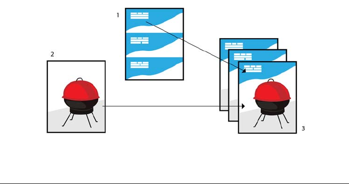
712 Corel DESIGNER X6 User Guide
To choose the maximum number of bitmap fonts
1Click To o l s Options.
2In the list of categories, double-click Global, and click Printing.
3Choose Bitmap font limit (PS) from the Special settings list.
4Choose a value from the Settings list box.
If you want to set a maximum bitmap font size, choose a font size from the Bitmap
font size threshold (PS) list box.
Using print merge
Corel DESIGNER lets you combine text from a data source with a drawing. When you
merge documents, you can produce several different copies of a drawing. You can use
merged documents to create personalized documents, such as mailing lists,
questionnaires, and targeted marketing documents, where each printed document
contains specific information from a record in a data source, such as a text file or an
ODBC data source (a Microsoft Excel or Microsoft® Access™ file).
When you merge documents, you create a form document in Corel DESIGNER and
combine it with a data source. A form document provides the pattern and layout for a
merged document. A data source supplies information for a drawing during the merge.
Corel DESIGNER supports the following data source files: Text (TXT) files,
comma-separated values (CSV) files, Rich Text Format (RTF) files, and files that can be
opened by means of an ODBC data source.
Data source document (1), form document (2), and merged documents (3)

Printing basics 713
Creating a data source file
Information in a data source file is organized into fields and records. A field can contain
one or more characters. Fields can contain alphanumeric data or only numeric data. For
example, a record may include a first name, last name, address, and other contact
information. Each item within the record, such as first name, last name, or address, is
recognized as a field. A record can contain one or more fields.
You can create a data source file or import an existing one. You can create a data text
file by using Corel DESIGNER or a text editor. You can edit the data in a data source
file at any time.
Creating a form document
Creating form documents is similar to creating regular drawings. For form documents,
however, you insert merge fields, which are replaced by information from the data
source during the merge.
Associating a form document with a data source file
When you use Corel DESIGNER to create a data file, or when you import an existing
data file into Corel DESIGNER, the data file is associated with the form document. The
association is always stored with the document and cannot be changed.
Performing a merge
Corel DESIGNERprovides different output options for merge documents. You can
print a merge document or save it to a new document. When you print a merge
document, the form document is merged with the data source file during printing.
When you save the merged document to a new file, the application merges the form
document with the data from the data source file in a new Corel DESIGNER file. You
can use this file to preview your final output and make minor adjustments before
printing. For major changes, such as the addition or repositioning of merge fields or the
addition of new records, you must work in the form document.
To create a data source file by using Corel DESIGNER
1Click File Print merge Create/Load merge fields to launch the Print merge
wizard.
2Enable the Create new text option, and click Next.
3On the Add fields page, do one or both of the following:

714 Corel DESIGNER X6 User Guide
• To create a text field, type a field name in the Te x t f i e l d box, click Add, and then
click Next.
• To create a numeric field, type a field name in the Numeric field box, click Add,
and then click Next.
4On the Add or edit records page of the Print merge wizard, do any of the
following:
• To add a record, click New, and then click Next.
• To add data in a field, click in the field, type data, and click Next.
• To modify existing data in a field, click in the field, modify the data, and click
Next.
5Enable the Save data settings as check box.
6Type a filename, choose the drive and folder where you want to save the file, and
click Finish.
You can also
Apply formatting to the data in a numeric
field
On the Add fields page of the Print merge
wizard, click a numeric field in the list, and
choose a format from the Numeric format
list box.
Different numeric formats are available in
Corel DESIGNER. For example, the X.0
format represents the value 1 as 1.0; the
00X format represents the value 1 as 001.
Automatically increment the value in a
numeric field
Enable the Continually increment the
numeric field check box, and specify
starting and ending values in the
corresponding boxes.
Change the order of merge fields Select a field in the list and click Move up or
Move down.
Delete a record On the Add or edit records page of the
Print merge wizard, click Delete.
Printing basics 715
You can edit the fields and records in an existing data source file by clicking
File Print merge Edit merge fields and following the instructions in the
Print merge wizard.
To create a data source by using a text editor
1Open a text editor, and create a new file.
2On the first line, type the number of merge fields that you want to insert in the
drawing. For example:
3
3On the second line, type the names of the merge fields by separating them with a
backslash. Each merge field must begin and end with a backslash. For example:
\Name\\Date\\Instructor\
4On the next lines, type the data that you want to appear in the merged document.
Each line constitutes a record. For example:
\Pixie Parsons\\6 September 2007\\Mr. Randy Harris\
View records On the Add or edit records page of the
Print merge wizard, choose one of the
following options from the Current view list
box:
•All records — lets you display all records
in a source data file
•Single record — lets you display one
record at a time
Browse records On the Add or edit records page of the
Print merge wizard, click any of the
following buttons:
•First record
•Next record
•Previous record
•Last record
Find text in a data file On the Add or edit records page of the
Print merge wizard, type a search term in
the box, and press Enter.
You can also

716 Corel DESIGNER X6 User Guide
\Shirley Wilkinson\\13 January 2007\\Ms. Corinne Pitts\
5Save the file as an ANSI text file (.txt extension) or as an RTF file.
Backslashes function as markers to indicate the beginning and end of merge
fields; therefore, you cannot use them as data in fields.
Data in fields must end with a character. Blank spaces or lines before
backslashes prevent the merge from being completed successfully.
To import a data source file
1Click File Print merge Create/Load merge fields.
2In the Print merge wizard, enable the Import text from a file or an ODBC data
source option, and click Next.
3Enable the File option, and navigate to the drive and folder where the data file is
stored.
4Choose a file.
5Click Open.
6Click Next.
7Follow the instructions in the Print merge wizard.
To import an ODBC data source file
1Click File Print merge Create/Load merge fields.
2In the Print merge wizard, enable the Import text from a file or an ODBC data
source option, and click Next.
3Enable the ODBC data source option, and click Select ODBC data source.
4In the Select data source dialog box, click the Machine data source tab.
5Under Data source name, select Excel files, and click OK.
6In the Select workbook dialog box, choose the database that you want to import,
and click OK.
To create a form document
1Open a drawing in which you want to insert merge fields.
2Click File Print merge Create/Load merge fields.

Printing basics 717
3Follow the instructions in the Print merge wizard to associate the drawing with a
data source file, and then exit the Print merge wizard.
The Print merge toolbar appears.
4On the Print merge toolbar, choose a field name from the Field list box, and click
Insert.
Corel DESIGNER places the merge field in the center of the current view. If you
want to reposition the merge field, drag it to a new location on the drawing page.
5Repeat step 4 to insert additional fields.
To perform a merge and print the document
1Do one of the following:
• Click File Print merge Perform merge.
• Click File Print. In the Perform merge dialog box, enable the Perform print
merge option, and click OK.
• On the Print merge toolbar, click Merge to new document, and click Print.
2Specify any printer settings.
3Click Print.
If you want to print all records and pages, enable the Current document option.
To perform a merge and save the document to a new file
•Click File Print merge Merge to new document.
You can also perform a merge and save the document to a new file by clicking
Merge to new document on the Print merge toolbar.
Viewing preflight summaries
Preflight checks the status of your file before you decide to output it and provides a
summary of issues and potential problems, and suggestions for resolving them. You can
specify which issues Preflight checks for. You can also save Preflight settings. For more
information about specific Preflight settings, see any of the following:
• To check for issues related to printing a file, see “To view a summary of issues for a
print job” on page 703.

718 Corel DESIGNER X6 User Guide
• To check for issues related to publishing a PDF file, see “To view the preflight
summary for a PDF file” on page 772.
• To check for issues related to exporting a SWF file, see “To view the issues summary
for an Adobe Flash file” on page 839.
• To check for issues related to exporting an SVG file, see “Scalable Vector Graphics
(SVG)” on page 833.

Preparing files for print service providers 719
Preparing files for print service
providers
With Corel DESIGNER, you can prepare a print job for sending to a print service
provider.
This section contains the following topics:
• Preparing a print job for a print service provider
• Working with imposition layouts
• Printing printers’ marks
• Maintaining OPI links
• Printing color separations
• Working with color trapping and overprinting
• Specifying In-RIP trapping settings
•Printing to film
• Working with a print service provider
Preparing a print job for a print service provider
You can print a drawing to a file, which lets the print service provider send the file
directly to an output device. If you are unsure about which settings to choose, consult
the print service provider.
For more information about commercial printing, see “Working with a print service
provider” on page 737.
To print to a file
1Click File Print.
2Click the General tab.
3In the Destination area, enable the Print to file check box.
4Click the flyout arrow, and click one of the following commands:
• For Mac — saves the drawing to be readable on a Macintosh computer

720 Corel DESIGNER X6 User Guide
• Single file — prints all pages in a document to a single file
• Pages to separate files — prints each page to a separate file
• Plates to separate files — prints each plate to a separate file
5Click Print.
6Choose one of the following from the Save as type list box:
• Print file — saves the file as a PRN file
• PostScript file — saves the file as a PS file
7Choose the folder where you want to save the file.
8Type a filename in the File name box.
9Click Save.
If you prefer not to prepare PostScript files, print service providers equipped
with the application in which you created your work can take the original files
(for example, Corel DESIGNER files) and apply the required prepress settings.
Working with imposition layouts
Working with imposition layouts lets you print more than one page of a document on
each sheet of paper. You can choose a preset imposition layout to create documents such
as magazines and books to print on a commercial printing press; produce documents
that involve cutting or folding, such as mailing labels, business cards, pamphlets, or
greeting cards; or print multiple thumbnails of a document on one page. You can also
edit a preset imposition layout to create your own layout.
You can select a binding method by choosing from three preset binding methods, or you
can customize a binding method. When you choose a preset binding method, all but
the first signature are automatically arranged.
You can arrange pages on a signature manually or automatically. When you arrange the
pages automatically, you can choose the angle of the image. If you have more than one
page across or down, you can specify the size of gutters between pages; for example, you
can choose the automatic gutter spacing option, which sizes gutters so that the
document’s pages fill the entire available space in the layout.
When printing on a desktop printer, you can adjust the margins to accommodate the
non-printable area of a page. If the margin is smaller than the non-printable area, the
edges of some pages or some printers’ marks may be clipped by your printer.

Preparing files for print service providers 721
To choose a preset imposition layout
1Click File Print.
2Click the Layout tab.
3Choose an imposition layout from the Imposition layout list box.
The layout you choose does not affect the original document, only the way it is
printed.
To edit an imposition layout
1Click File Print.
2Click the Layout tab.
3Choose an imposition layout from the Imposition layout list box.
4Click Edit.
5Edit any imposition layout settings.
6Click File Save imposition layout.
7Type a name for the imposition layout in the Save as box.
When editing an imposition layout, you should save it with a new name;
otherwise the settings for a preset imposition layout will be overwritten.
To select a binding method
1Click File Print preview.
2Click the Imposition layout tool .
3Choose Edit basic settings from the What to edit list box on the property bar.
4Type values in the Pages across/down boxes.
If you want the page to be double-sided, click the Single/double sided button .
5Choose one of the following binding methods from the Binding mode list box:
• Perfect binding — cuts apart individual pages and glues them at the spine
• Saddle stitch — folds pages and inserts them into one another
• Collate and cut — collates and stacks all signatures together
• Custom binding — lets you arrange the pages that are printed in each signature
722 Corel DESIGNER X6 User Guide
If you choose either Saddle stitch or Custom binding, type a value in the
corresponding box.
When you click the Single/double sided button for double-sided printing,
and you are printing on a non-duplex printing device, a wizard automatically
provides instructions on how to insert the paper into the printer, so that you
can print on both sides of the page.
To arrange pages
1Click File Print preview.
2Click the Imposition layout tool .
3Choose Edit page placements from the What to edit list box on the property bar.
4Click one of the following buttons:
• Intelligent auto-ordering — automatically arranges the pages on a
signature
• Sequential auto-ordering — arranges the pages from left to right and top
to bottom
• Cloned auto-ordering — places the working page in each frame of the
printable page
If you want to arrange the page numbering manually, click on the page and specify
the page number in the Page sequence number box.
5Choose an angle from the Page rotation list box.
To edit gutters
1Click File Print preview.
2Click the Imposition layout tool .
3Choose Edit gutters and finishing from the What to edit list box on the property
bar.
4Click one of the following buttons:
• Auto gutter spacing — sizes gutters so that the document’s pages fill the
entire available space in the layout
• Equal gutters — lets you set equal horizontal and vertical gutters
5Click one of the following buttons:
• Cut location — places cut marks between pages
Preparing files for print service providers 723
• Fold location — places fold marks between pages
If you click the Equal gutters button, you must specify a value in the Gutter
size box.
You can edit the gutters only if you’ve selected an imposition layout with two
or more pages across and down.
To adjust margins
1Click File Print preview.
2Click the Imposition layout tool .
3Choose Edit margins from the What to edit list box on the property bar.
4Click one of the following buttons:
• Auto margins — sets the margins automatically
• Equal margins — lets you make the right margin equal to the left one, and
the bottom margin equal to the top one
If you click the Equal margins button, you must specify values in the To p / l e f t
margin boxes.
When preparing a job for a commercial press, the print service provider may
request minimum margin sizes, such as for page grippers and printers’ marks.
Printing printers’ marks
Printing printers’ marks lets you display information on a page about how a document
should be printed.The available printers’ marks are as follows:
•Crop/fold marks — represent the size of the paper and print at the corners of the
page. You can print crop/fold marks to use as guides to trim the paper. If you print
multiple pages per sheet (for example, two rows by two columns), you can choose
to print the crop/fold marks on the outside edge of the page so that all crop/fold
marks are removed after the cropping process, or you can choose to add crop marks
around each row and column. Crop/fold marks ensure that marks appear on each
plate of a separated CMYK file.
•Bleed limit — determines how far an image can extend beyond the crop marks.
When you use a bleed to extend the print job to the edge of the page, you must set
a bleed limit. A bleed requires that the paper you are printing on is larger than the

724 Corel DESIGNER X6 User Guide
size of paper you ultimately want, and the print job must extend beyond the edge
of the final paper size.
•Registration marks — are required to line up film for proofing or printing plates
on a color press. They print on each sheet of a color separation.
•Color calibration bars — are color scales that print on each sheet of a color
separation and ensure accurate color reproduction. To see calibration bars, make
sure that the page size of the print job is larger than the page size of the work you
are printing.
•Densitometer scale — is a series of gray boxes ranging from light to dark. These
boxes are required to test the density of halftone images. You can position the
densitometer scale anywhere on the page. You can also customize the levels of gray
that appear in each of the seven squares on the densitometer scale.
•Page numbers — helps you collate pages of an image that do not include any
page numbers or do not contain page numbers that correspond to the actual
number of pages
•File information — prints file information, such as, the color profile; halftone
settings; name, date, and time the image was created; plate number; and job name
To print crop and fold marks
1Click File Print.
2Click the Prepress tab.
3In the Crop/folds marks area, enable the Crop/fold marks check box.
If you want to print all crop/fold marks, disable the Exterior only check box.
To print crop and fold marks, ensure that the paper on which you print is 0.5
inches larger on all sides than the page size of the image that you are printing.
To set crop and fold marks, see “To edit gutters” on page 722.
To print composite crop and fold marks
1Click To o l s Options.
2In the list of categories, double-click Global, and click Printing.
3Choose Composite crop marks (PS) from the Option list.
4Choose Output on all plates from the Setting list box.

Preparing files for print service providers 725
To set a bleed limit
1Click File Print.
2Click the Layout tab.
3Enable the Bleed limit check box.
4Type a value in the Bleed limit box.
Usually, a bleed limit of 0.125 to 0.25 inches is sufficient. Any object
extending beyond that uses memory needlessly and may cause problems when
you print multiple pages with bleeds on a single sheet of paper.
To print registration marks
1Click File Print.
2Click the Prepress tab.
3In the Registration marks area, enable the Print registration marks check box.
4Choose a registration mark style from the Style picker.
To print registration marks, ensure that the paper on which you print is 0.5
inches larger on all sides than the page size of the image that you are printing.
To print color calibration bars and densitometer scales
1Click File Print.
2Click the Prepress tab.
3In the Calibration bars area, enable any of the following check boxes:
• Color calibration bar
• Densitometer scales
If you want to customize the levels of gray in one of the densitometer scale squares,
choose a number from the Densities list (lower values represent lighter squares),
and type a new density for that square.
To print page numbers
1Click File Print.
2Click the Prepress tab.
726 Corel DESIGNER X6 User Guide
3In the File information area, enable the Print page numbers check box.
If you want to position the page number inside the page, enable the Position
within page check box.
To print file information
1Click File Print.
2Click the Prepress tab.
3In the File information area, enable the Print file information check box.
4Type a job name in the Print file information box.
If you want to position the file information inside the page, enable the Position
within page check box.
To position printers’ marks
1Click File Print preview.
2Click the Marks placement tool .
3Click the Auto-position marks rectangle button on the property bar.
4Type values in the Marks alignment rectangle boxes.
You can also change the position of printers’ marks by clicking a printers’ mark
icon in the print preview window and dragging the bounding box.
If you want to affix printers’ marks to the object’s bounding box instead of to
the page bounding box, click File Print, click the Prepress tab, and enable
the Marks to objects check box.
Maintaining OPI links
Open Prepress Interface (OPI) lets you use low-resolution images as placeholders for the
high-resolution images that appear in your final work. When a print service provider
receives your file, the OPI server substitutes the high-resolution images for the low-
resolution placeholders.
To maintain OPI links
1Click File Print.

Preparing files for print service providers 727
2Click the PostScript tab.
3Enable the Maintain OPI links check box.
The Maintain OPI links option is available for PostScript devices only.
You can reduce your work time by using OPI and print management server
solutions, such as Creo® Color Central®. Low-resolution samples are
automatically created from the high-resolution originals and are placed in
Corel DESIGNER. These files contain their own OPI comments, which the
Creo Color Central server recognizes when it receives the job and then
substitutes the high-resolution version of the file for the low-resolution version.
Low-resolution images must be flagged as OPI images (this must be done
using third-party software) before you can import them into a document.
Printing color separations
When you send color work to a print service provider or printing shop, either you or the
print service provider must create color separations. Color separations are necessary
because a typical printing press applies only one color of ink at a time to a sheet of paper.
You can specify the color separations to print, including the order in which they print.
Printing presses produce color using either process color or spot color, or both. You can
convert the spot colors to process colors at printing time. For more information on spot
and process colors, see “Choosing colors” on page 337.
When setting halftone screens to print color separations, we recommend that you use
the default settings; otherwise, screens can be improperly set and result in undesirable
moiré patterns and poor color reproduction. However, if you are using an imagesetter,
the screen technology should be set to match the type of imagesetter the print service
provider uses. Before customizing a halftone screen, consult the print service provider
to determine the correct setting.
If you have overprinted areas, you can choose how you want those areas to print. For
more information about overprinting, see “Working with color trapping and
overprinting” on page 729.
To print color separations
1Click File Print.
2Click the Color tab.

728 Corel DESIGNER X6 User Guide
3Enable the Print separations option.
If you want to print specific color separations, click the Separations tab, and
enable the corresponding check box in the list of color separations.
You can change the order in which color separations print, by enabling the Use
advanced settings check box in the Options area. In the separations list at the
bottom of the dialog box, click in the Order column next to the color
separation that you want to change. Chose a new order value from the list box.
If you want to print separations using a color profile that is different from the
document color profile, you can click the Color tab and choose a color profile
from the Correct colors using color profile list box.
To convert spot colors to process colors
1Click File Print.
2Click the Color tab.
3Enable the Print separations option.
4Enable the Convert spot colors to check box.
Changing the spot colors to process colors does not affect the original
Corel DESIGNER file; it affects the way colors are sent to the printer.
To customize a halftone screen
1Click File Print.
2Click the Color tab.
3Enable the Print separations option.
4Click the Separations tab.
5In the Options area, enable the Use advanced settings check box.
6Click Advanced.
7Change any of the following settings:
• Screening technology
• Resolution
• Basic screen
• Halftone type

Preparing files for print service providers 729
You can set the screen frequency, screen angle, and overprint options for spot
colors as well as process colors. For example, if you have a fountain fill made up
of two spot colors, you can set one to print at 45 degrees and the other at 90
degrees.
Working with color trapping and overprinting
When colors are trapped, they are intentionally overlapped so that misalignments of
print separations are not noticeable. In manual trapping, one color must overprint the
other. Overprinting is achieved by printing one color over another. Overprint trapping
works best when the top color is much darker than the underlying color; otherwise, an
undesirable third color may result (for example, cyan over yellow results in a green
object). In some cases, you might actually want to create a third color; for example, you
can overprint two spot colors to create a third color.
How overprinted colors mix depends on the type of colors and ink you are mixing and
the types of objects you are overprinting. For example, an object that uses a CMYK
color overprints differently from an object that uses a spot color. Bitmaps also overprint
differently from vector objects. You can preview a simulation of how overprinted colors
will mix by enabling the Enhanced viewing mode and the Simulate overprints
viewing mode. For more information about choosing a viewing mode, see “Choosing
viewing modes” on page 70. Some variation between the preview and the printed
version may occur, depending on the printer you use.
When you are ready to print, you can choose to preserve overprint settings if you want
to trap objects in a document, or if you want to mix the overlapping colors for effect.
You can also choose to knock out the overprinted areas so that only the top color is
visible. If you want to print a proof version of the file, you can simulate overprints.
Simulating overprints rasterizes the file, and it prints using process colors only.
You can set a group of objects to overprint. You can allow text to overprint overlying
objects. You can also overprint bitmaps; or each vector object’s fill, or outline, or both.
In addition, you can overprint specific color separations and specify in which order they
will print, as well as whether you want to overprint graphics, or text, or both.
The two methods for automatic color trapping include always overprinting black and
auto-spreading. Overprinting black creates a color trap by causing any object that
contains 95% black or more to overprint any underlying objects. This option is useful
for artwork containing a lot of black text, but it should be used with caution on artwork

730 Corel DESIGNER X6 User Guide
with a high graphics content. You can adjust the threshold, if the print service provider
recommends a black threshold value other than 95%.
Auto-spreading creates color trapping by assigning an outline to an object that is the
same color as the object’s fill and having it overprint underlying objects. Auto-spreading
is created for all objects in the file that meet three conditions: they do not already have
an outline, are filled with a uniform fill, and have not already been designated to
overprint.
For advanced trapping options, see “Specifying In-RIP trapping settings” on page 733.
To preserve or ignore overprints when printing
1Click File Print.
2Click the Color tab.
3Choose one of the following options:
• Print composite
• Print separations
4Click one of the following tabs:
• Separations
• Composite
5From the Document overprints list box, choose one of the following options:
• Ignore — does not overprint areas; color on top prints and underlying colors are
knocked out
• Preserve — preserves overprinted areas
To print a simulated overprint
1Click File Print.
2Click the Color tab.
3Enable the Print composite option.
4Click the Composite tab.
5From the Document overprints list box, choose Simulate.
The Simulate option rasterizes the file; the file is printed with process colors.
To overprint selected objects
1Select an object.

Preparing files for print service providers 731
2Click Edit, and choose any of the following:
• Overprint outline
• Overprint fill
• Overprint bitmap
You can also set an object to overprint by right-clicking the object and
choosing an overprint option from the context menu.
To overprint selected color separations
1Click File Print.
2Click the Color tab.
3Enable the Print separations option.
4Click the Separations tab.
5In the Options area, enable the Use advanced settings check box.
6Click Advanced.
7In the Advanced separations settings dialog box, choose a color separation from
the Screening technology list box.
8In the Overprint column, click one or both of the following icons:
• Overprint graphics
• Overprint text
The icons appear darker when the separation is set to overprint.
You can change the order in which color separations print by selecting a color
separation and choosing an order from the Order list box.
To trap by always overprinting black
1Click File Print.
2Click the Color tab.
3Choose one of the following options:
• Print composite
• Print separations
4Click one of the following tabs:

732 Corel DESIGNER X6 User Guide
• Separations
• Composite
5In the Options area, enable the Always overprint black check box.
To set the overprint black threshold
1Click To o l s Options.
2In the list of categories, double-click Global, and click Printing.
3Choose Overprint black threshold (PS) from the Option list.
4Choose a number from the Setting list box.
The number you choose represents the percentage of black above which black
objects overprint.
To trap by auto-spreading
1Click File Print.
2Click the Color tab.
3Choose one of the following options:
• Print composite
• Print separations
4Click one of the following tabs:
• Separations
• Composite
5In the PostScript trapping or Trapping area, do one of the following:
• Enable the Auto-spreading option, and type a value in the Maximum box.
• Enable the Fixed width option, and type a value in the Width box.
6Type a value in the Te x t a b o v e box.
The value that you type in the Te x t a b o v e box represents the minimum size to
which auto-spreading is applied. If you set this value too low, small text may
be rendered illegible when auto-spreading is applied.
The amount of spread assigned to an object depends on the maximum trap
value specified in the Maximum box and the object’s color. The lighter the
color, the greater the percentage of the maximum trap value. The darker the
color, the smaller the percentage of the maximum trap value.

Preparing files for print service providers 733
Specifying In-RIP trapping settings
In-RIP trapping allows you to specify advanced trapping settings. Before selecting In-
RIP trapping, ensure that your PostScript 3 printer supports In-RIP trapping options.
You can select a trap width — the amount that one color spreads into another. You can
also specify image trap placement, which determines where the trap occurs. You can, for
example, specify whether the trap is a choke or a spread, depending upon the neutral
densities of adjacent colors. Neutral density indicates the lightness or darkness of a color
and helps determine how adjacent colors spread into one another.
You can specify a threshold at which a trap is created by specifying a step trap limit. If
trap colors are of similar neutral densities, the trap placement adjusts accordingly. The
step trap limit specifies a threshold at which a trap adjusts.
Before trapping, you can set the inks; for example, you can set an ink to opaque, as in
the case of a metallic ink, so that nothing shows through it. To reduce the visibility of a
trap, you can decrease the amount of ink color in a trap. This is especially helpful in the
case of pastel colors, contrasting colors, and colors with similar neutral densities.
To select a trap width
1Click File Print.
2Click the Color tab.
3Enable the Print composite option.
4Click the PostScript tab.
5Choose PostScript 3 from the Compatibility list box.
6Click the Composite tab.
7Enable the PostScript level 3 In-RIP trapping check box.
8Click Settings.
9Type a value in the Tr a p w i d t h box.
If you are trapping to black, type a value in the Black trap width box.
To select In-RIP trapping options, you must have selected PostScript 3 from
the Compatibility list box under the PostScript tab of the Print dialog box.

734 Corel DESIGNER X6 User Guide
To specify image trap placement
1Click File Print.
2Click the Color tab.
3Enable the Print composite option.
4Click the PostScript tab.
5Choose PostScript 3 from the Compatibility list box.
6Click the Composite tab.
7Enable the PostScript Level 3 In-RIP trapping check box.
8Click Settings.
9From the Image trap placement list box, choose one of the following placements:
• Neutral density — used to determine the lighter object and thus the direction
and placement of the trap
• Choke — used to trap a dark foreground object to a light background image
• Spread — used to trap a light foreground object to a dark background image
• Centerline — used when adjacent images and objects have similar neutral
densities or when image density changes along an object’s edge
If you want to trap an object to an image, enable the Trap objects to images
check box.
To specify a threshold
1Click File Print.
2Click the Color tab.
3Enable the Print composite option.
4Click the PostScript tab.
5Choose PostScript 3 from the Compatibility list box.
6Click the Composite tab.
7Enable the PostScript 3 In-RIP trapping check box.
8Click Settings.
9Type a value in one or more of the following boxes:
• Step limit — specifies a threshold between color variations. The lower the
threshold value, the more likely it is that a trap will be created.
• Black limit — specifies the threshold at which process black is considered pure
black

Preparing files for print service providers 735
• Black density limit — specifies a neutral density value for the black ink
• Sliding trap limit — specifies the difference between the neutral densities of
adjacent colors at which a trap adjusts (slides) from the darker side of a color edge
toward the centerline. The lower the sliding trap limit, the more gradual the
transition.
To choose In-RIP trapping options, you must have selected PostScript 3 from
the Compatibility list box under the PostScript tab in the Print dialog box.
To set inks for trapping
1Click File Print.
2Click the Color tab.
3Enable the Print composite option.
4Click the Composite tab.
5Enable the PostScript Level 3 In-RIP trapping check box.
6Click Settings.
7In the Ty p e column, select one of the following for each color separation:
• Tr a n s p a r e n t — the selected ink doesn’t get trapped, but anything beneath it
does
• Neutral density — the neutral density of the selected ink determines how it is
treated
• Opaque — the selected ink is treated as opaque
• Opaque ignore — the selected ink doesn’t get trapped nor does anything
beneath it
To choose In-RIP trapping options, you must have selected PostScript 3 from
the Compatibility list box under the PostScript tab in the Print dialog box.
To select a trap color reduction
1Click File Print.
2Click the Color tab.
3Enable the Print composite option.
4Click the Composite tab.

736 Corel DESIGNER X6 User Guide
5Enable the PostScript 3 In-RIP trapping check box.
6Click Settings.
7Type a value in the Trap color reduction box.
A reduction value of 100% indicates no reduction, while a lower value reduces
the neutral density.
Printing to film
You can set up a print job to produce negative images. An imagesetter produces images
on film that may need to be produced as negatives depending on which printing device
you are using. Consult your print service provider to determine whether you can
produce images on film.
You can specify to print with the emulsion down. Printing with the emulsion down
produces a backward image on desktop printers.
To print a negative
1Click File Print.
2Click the Prepress tab.
3In the Paper/film settings area, enable the Invert check box.
Do not choose negative film if you are printing to a desktop printer.
To specify film with the emulsion down
1Click File Print.
2Click the Prepress tab.
3In the Paper/film settings area, enable the Mirror check box.

Preparing files for print service providers 737
Working with a print service provider
When you send a file to a print service provider, the provider takes your file and converts
it directly to film or to plates.
When you prepare a print job for printing, you can send camera-ready paper output or
the work on disk. If you send the work on disk, the print service provider needs either
a PostScript file or a native file from the application that you use. If you are creating a
file to send to an imagesetter or a plate-setter, speak with the print service provider
about the best file format and printing device settings to use. Always provide a final
printout of the work to the print service provider, even if it is only a black-and-white
representation. This helps the print service provider to identify and assess any potential
problems.
Before printing a drawing, you must choose and properly configure the appropriate
printing device driver. Consult the printing device manufacturer instructions, or the
print service provider or printing shop that you use to print the work, to find out the
best way to set up the printing device driver.

File formats 739
File formats
Importing and exporting files . . . . . . . . . . . . . . . . . . . . . . . . . . . . . . . . .741
Working with 3D models . . . . . . . . . . . . . . . . . . . . . . . . . . . . . . . . . . . .751
Exporting to PDF . . . . . . . . . . . . . . . . . . . . . . . . . . . . . . . . . . . . . . . . . . .757
Working with office productivity applications . . . . . . . . . . . . . . . . . . . .777
Exporting to HTML . . . . . . . . . . . . . . . . . . . . . . . . . . . . . . . . . . . . . . . . .779
Supported file formats . . . . . . . . . . . . . . . . . . . . . . . . . . . . . . . . . . . . . .783

Importing and exporting files 741
Importing and exporting files
Your application provides filters that convert files from one format to another when
you import or export files.
This section contains the following topics:
•Importing files
•Exporting files
Importing files
You can import files created in other applications. For example, you can import an
Adobe Portable Document Format (PDF), JPEG, or Adobe Illustrator (AI) file. You can
import a file and place it in the active application window as an object. You can also
resize and center a file as you import it. The imported file becomes part of the active file.
You can also import a bitmap as an externally linked image. When you import a linked
bitmap, edits to the original (external) file are automatically updated in the imported
file.
While importing a bitmap, you can resample it to reduce the file size, or crop it to
eliminate unused areas of the image. You can also crop a bitmap to select only the exact
area and size of the image that you want to import.
When you import a file from an earlier version of Corel DESIGNER that contains text
in a language different from the language of your operating system, you can use code
page settings to ensure that object names, keywords, and notes saved with the file are
displayed correctly.
To import a file into an active drawing
1Click File Import.
2Choose the folder where the file is stored.

742 Corel DESIGNER X6 User Guide
If necessary, you can search for a file by using the search box. You can search for
such things as file name, title, subject, author, keyword, comment, bitmap name,
object name, and so on.
3Choose a file format from the list box next to the File name box (Windows 7 and
Windows 8) or the Files of type list box (Windows XP).
If you don’t know the file’s format, choose All file formats.
4Click the file name.
If the file contains text in a language different from that of your operating system,
choose the corresponding option from the Select code page list box (Windows 7
and Windows 8) or Code page list box (Windows XP) to ensure that object names,
keywords, and notes are correctly displayed.
These options are not available for all file formats.
5Click Import, and do one of the following:
• Click the drawing page to maintain the dimensions of the file and position its
top-left corner where you click.
• Drag on the drawing page to resize the file. The import cursor displays the
dimensions of the resized file as you drag on the drawing page.
• Press Enter to center the file on the drawing page.
• Press the Spacebar to place the file in the same position as it was in the original
file (CDR and AI files only).
Active snapping options are applied to the imported file.
You can also
Link to a bitmap externally instead of
embedding it
Click the arrow on the Import button, and
then click Import as externally linked
image (Windows 7 and Windows 8) or
enable the Link bitmap externally check
box (Windows XP).
If you want to display a list of the linked
images, click Window Dockers Links
and bookmarks.

Importing and exporting files 743
Link to a high-resolution file for Open
Prepress Interface (OPI) output
Click the arrow on the Import button, and
then click Import as high-resolution file
for output using OPI (Windows 7 and
Windows 8) or enable the Link to high-
resolution file for output using OPI check
box (Windows XP).
This procedure inserts a low-resolution
version of a TIFF or Scitex® Continuous
Tone (CT) file into a document. The low-
resolution version is linked to the high-
resolution image, which resides on an Open
Prepress Interface (OPI) server.
Merge layers in an imported bitmap Enable the Combine multi-layer bitmap
check box.
Save the embedded International Color
Consortium (ICC) profile
Enable the Extract embedded ICC profile
check box to save the ICC profile to the color
folder where the application is installed.
This option is not available for all file
formats.
Check for watermark or copyright
information
Enable the Check for watermark check
box.
This option is not available for all file
formats.
Use the default settings for the filter instead
of opening the dialog box
Enable the Do not show filter dialog check
box.
This option is not available for all file
formats.
Preserve layers and pages in an imported file Enable the Maintain layers and pages
check box. If you disable the check box, all
layers are combined into a single layer.
This option is not available for all file
formats.
You can also
744 Corel DESIGNER X6 User Guide
Not all importing options are available for all file formats.
You can import multiple files. Hold down Shift and click to select consecutive
files in a list. Hold down Ctrl and click to select non-consecutive files.
To import a bitmap as an externally linked image
1Click Window Links and bookmarks.
2In the Links and bookmarks docker, click the New linked image button.
3Browse to the drive and folder where the image is stored.
4Click Import.
5Click in the workspace to place the image.
To resample a bitmap while importing
1Click File Import.
2Choose the folder where the image is stored.
3Choose a file format from the Files of type list box.
4Click the file name.
Select the pages to import when importing
multi-page TIFF documents
In the Import TIFF dialog box, enable an
option in the Select the page(s) to import
area.
This option is available only for the TIFF file
format.
Open only part of an image (Windows 7 and
Windows 8)
In the Load partial file dialog box, type the
range of frames to open in the Load frames
box.
You can also
Update a linked image Click the Update linked image button.
Break the link to an externally linked image Click the Break link button.
You can also
Importing and exporting files 745
5Do one of the following:
• (Windows 7 and Windows 8) Click the arrow next to the Import button, and
then click Resample and load.
• (Windows XP) Choose Resample from the list box beside the Files of type list
box, and click Import.
6In the Resample image dialog box, type values in any of the following boxes:
• Width — specifies the width of the graphic in a chosen unit of measure or as a
percentage of its original width
• Height — specifies the height of the graphic in a chosen unit of measure or as a
percentage of its original height
7In the Resolution area, type values in the following boxes:
• Horizontal — lets you specify the horizontal resolution of the graphic in pixels
or dots per inch (dpi)
• Vertical — lets you specify the vertical resolution of the graphic in pixels or dots
per inch (dpi)
8Click the drawing page.
If a dialog box for the import format opens, specify the options you want. For
detailed information about file formats, see “Supported file formats” on
page 783.
Not all importing options are available for all file formats.
To crop a bitmap while importing
1Click File Import.
2Choose the folder where the image is stored.
3Choose a file format from the Files of type list box.
4Click the file name.
You can also
Maintain the width-to-height ratio of the
image
Enable the Maintain aspect ratio check
box.
Change the unit of measure Choose a unit type from the Units list box.
Maintain equal horizontal and vertical
resolution values automatically
Enable the Identical values check box.

746 Corel DESIGNER X6 User Guide
5Do one of the following:
• (Windows 7 and Windows 8) Click the arrow next to the Import button, and
click Crop and load.
• (Windows XP) Choose Crop from the list box beside the Files of type list box,
and click Import.
6In the Crop image dialog box, type values in any of the following boxes:
• To p — specifies the area to remove from the top of the graphic
• Left — specifies the area to remove from the left edge of the graphic
• Width — specifies the width of the graphic that you want to keep
• Height — specifies the height of the graphic that you want to keep
7Click the drawing page.
You can also resize a graphic by dragging the selection handles in the preview
window.
You can change the unit of measure by choosing a unit type from the Units
list box in the Crop image dialog box.
Exporting files
Yo u c a n u s e t h e File Export command to export files to a variety of bitmap and vector
file formats that can be used in other applications. For example, you can export a file to
the Adobe Illustrator (AI) or JPG format. You can also export a file so that it is
optimized for use with a suite of office productivity applications, such as Microsoft
Office or Corel WordPerfect Office.
When you are exporting a file, the original file is left open in the drawing window in its
existing format.
You can use the File Save as command to save files to various vector formats. After
you save a file to a different format, the saved file is displayed immediately in the
drawing window. It is recommended that you first save the file as a Corel DESIGNER
file because some file formats do not support all of the features found in a
Corel DESIGNER file.
To export a file
1Click File Export.
2Choose the folder where you want to save the file.

Importing and exporting files 747
3Choose a file format from the Save as type list box.
4Ty p e a f i l e n a m e i n t h e File name list box.
5Enable any of the following check boxes:
• Export this page only — exports only the current page in a multipage file
• Selected only — saves only the objects selected in the active drawing
• Do not show filter dialog — suppresses dialog boxes that offer more advanced
exporting options
These options are not available for all file formats.
6Click Export.
If a dialog box for the export format opens, specify the options you want. For
detailed information about file formats, see “Supported file formats” on page 783.
Not all of the options or compression types in the Export dialog box are
available for all file formats.
Objects on a hidden layer are displayed in the exported file unless the printing
and exporting function for the hidden layer is disabled.
For information about the options available when you export to a bitmap file
format, see “To convert a vector graphic to a bitmap when exporting” on
page 635.
If you are using an expired trial version, you will not be able to export files.
You can specify which layers will appear in the exported file. For more
information, see “To enable or disable printing and exporting of a layer” on
page 312.
To export a file to Microsoft Office or WordPerfect Office
1Click File Export for Office.
You can also
Compress a file on export Choose a compression type from the
Compression type list box.
Specify information about a file Type any comments you want in the Notes
box.
748 Corel DESIGNER X6 User Guide
2From the Export to list box, choose one of the following:
• Microsoft Office — lets you set options to meet the output requirements of
Microsoft Office applications
• WordPerfect Office — optimizes the image for Corel WordPerfect Office by
converting it to a WordPerfect Graphics file (WPG)
3If you chose Microsoft Office, choose one of the following options from the
Graphic should be best suited for list box:
• Compatibility — lets you save the drawing as a Portable Network Graphic
(PNG) bitmap. This preserves the appearance of the drawing when you import it
into an office application.
• Editing — lets you save the drawing in the Extended Metafile Format (EMF).
This retains most of the editable elements in vector drawings.
4If you chose Microsoft Office and Compatibility, choose one of the following
options from the Optimized for list box:
• Presentation — lets you optimize the file for outputs such as slide shows or
online documents (96 dpi)
• Desktop printing — lets you maintain good image quality for desktop printing
(150 dpi)
• Commercial printing — lets you optimize the file for high-quality printing
(300 dpi)
An estimated file size appears in the lower-left corner of the dialog box.
5Click OK.
6Locate the folder in which you want to save the file.
7Ty p e a f i l e n a m e i n t h e File name list box.
8Click Save.
The Graphic should be best suited for and Optimized for options are
available only if you choose the Microsoft Office and Compatibility options.
You can also
Zoom in and out in the preview window Using the Zoom in or Zoom out
tool, click in the preview window.
Pan to view another area of the drawing Using the Pan tool , drag in the preview
window until the area that you want to see
becomes visible.
Importing and exporting files 749
Layers in a drawing are flattened when exported to Microsoft Office or
Corel WordPerfect Office.
To save a file to a different format
1Click File Save as.
2Choose the folder where you want to save the file.
3Choose a file format from the Save as type list box.
4Ty p e a f i l e n a m e i n t h e File name list box.
5Enable any of the following check boxes:
• Selected only — saves only the objects selected in the active drawing
• Save with embedded VBA project — lets you save, with the file, macros you
have created in the VBA editor
These options are not available for all file formats.
6Click Save.
Not all of the options or the compression types in the Save drawing dialog box
are available for all file formats.
You can also
Specify information about a file Type any comments you want in the Add
comments box (Windows 7 and
Windows 8) or Notes box (Windows XP).
Add keywords Type any keywords you want in the Add a
tag box (Windows 7 and Windows 8) or
Keywords box (Windows XP).

Working with 3D models 751
Working with 3D models
CorelDRAW Technical Suite X6 includes software that lets you add three-dimensional
(3D) models to your technical illustrations. By using XVL Studio 3D Corel Edition, a
3D-authoring application produced by Lattice Technology, you can view 3D models
and import them as 2D vector graphics when you work with Corel DESIGNER.
This section contains the following topics:
• Installing XVL Studio 3D Corel Edition
• Importing 3D models
• Inserting and adjusting 3D models
Installing XVL Studio 3D Corel Edition
To work with 3D models, you must install XVL Studio 3D Corel Edition, the 3D-
authoring application that is included with CorelDRAW Technical Suite X6.
You can install XVL Studio 3D Corel Edition while you install
CorelDRAW Technical Suite X6, or you can update your installation later to include
XVL Studio 3D Corel Edition.
You can upgrade your version of XVL Studio 3D Corel Edition to XVL Studio 3D CAD
Corel Edition to receive these exclusive features:
• Additional native 3D CAD file format support to ensure support for assemblies and
parts from 3D CAD systems, including CATIA®, Inventor®, PTC Creo,
SolidWorks®, NX™ and more
• Support for many 3D CAD exchange file formats to easily access and re-purpose
files saved to IGES, STEP, JT, and other commonly used file formats
• Output 3D files as U3D (for 3D PDF)
• Import and export metadata (for example, part lists)
• Advanced tools for Disassembly views to illustrate assembly and maintenance
instructions
• 3D Dimension and Measurement tools

752 Corel DESIGNER X6 User Guide
• Animation tools
For more detailed information about XVL Studio 3D Corel Edition and direct
comparison to XVL Studio 3D CAD Corel Edition, please visit www.corel.com/
designer.
Trial versions of CorelDRAW Technical Suite X6 include a trial version of XVL Studio
3D CAD Corel Edition that will become deactivated after the trial period expires.
When you convert a trial version of CorelDRAW Technical Suite X6 to a fully licensed
software package, XVL Studio 3D Corel Edition becomes available. You can purchase
an unlock key to upgrade to XVL Studio 3D CAD Corel Edition from the corel.com
estore or by launching XVL Studio 3D Corel Edition and clicking Help XVL Studio
3D CAD Corel Edition.
To update a CorelDRAW Technical Suite X6 installation to include XVL Studio
3D Corel Edition
1Close any open programs.
2Insert the disc in the DVD drive of your computer.
3On the Windows taskbar, click Start Control panel.
4Do one of the following:
• (Windows 7 and Windows 8) Click Uninstall a program.
• (Windows XP) Click the Add or remove programs icon.
5Do one of the following:
• (Windows 7 and Windows 8) Double-click CorelDRAW Technical Suite X6
from the Uninstall or change a program page.
• (Windows XP) Choose CorelDRAW Technical Suite X6 from the Currently
installed programs list, and click Change/Remove.
6In the installation wizard, enable the Modify option.
7Click Next.
8In the Programs list, enable the XVL Studio 3D Corel Edition check box.
9Click Install now.
Importing 3D models
Corel DESIGNER lets you add 3D models as 2D vector graphics to your illustrations.
Before importing a graphic into Corel DESIGNER, you must open it with XVL Studio

Working with 3D models 753
3D Corel Edition. After you open the 3D image, you can preview it from different
angles. For example, you can specify parallel or perspective projected views. You can
also change the position, orientation, and size of a 3D model, and you can create cross-
sections. When you are satisfied with the view of the 3D model in XVL Studio 3D
Corel Edition, you can import it as a 2D vector graphic into the active drawing or save
it for later use.
XVL Studio 3D Corel Edition lets you import files saved to the following 3D file
formats:
• AutoCAD® (DWG and DXF)
•3ds Max® (3DS)
•VRML
• Universal 3D (U3D)
If you want to use additional file formats, you can upgrade to XVL Studio 3D CAD
Corel Edition, which supports native 3D CAD file formats including CATIA®,
SolidWorks®, Autodesk® Inventor®, and NX™. It also supports 3D CAD exchange
formats such as JT, IGES, STEP, and Parasolid®.
For a detailed list of the 3D CAD file formats supported by XVL Studio 3D CAD Corel
Edition, see the Help system within XVL Studio 3D Corel Edition.
To import a 3D model
1Click File 3D Import.
If this menu command is not available, you must install XVL Studio 3D Corel
Edition.
2In XVL Studio 3D Corel Edition, open and adjust the 3D model that you want to
import.
3Click File Send to Corel DESIGNER.
If you want to adjust the size and position of the 2D graphic, specify the settings
you want in the Send to Corel DESIGNER dialog box.
4Click Send.
You can also
Access Help In XVL Studio 3D Corel Edition, click Help
Help.

754 Corel DESIGNER X6 User Guide
Inserting and adjusting 3D models
You can insert and view 3D models in Corel DESIGNER by using the embedded
interface of XVL Player, a 3D viewer for XVL® files. In addition, you can use the
controls of the XVL player to adjust the view of the 3D model by panning, rotating,
zooming, and choosing a different view.
Inserted 3D models are linked with the source 3D files. Any adjustments that you make
to an inserted file affect the source file. You can break the link between the inserted files
and the source 3D files at any time.
To insert a 3D model
1Click File Insert 3D model.
If this menu command is not available, you must update your installation to
include XVL Player. For more information, see “To modify or repair a
CorelDRAW Technical Suite installation” on page 4.
2Locate and open the XVL file that you want to insert.
3Drag in the drawing window to insert the file at the desired size and position.
You can insert only 3D models saved to the XVL® file format. To insert a 3D
model saved to another file format, you must first import it (File 3D
Import), save it as an XVL file (including snapshots, animations, and cross
section), and then insert it.
Export a 3D model In the Send to Corel DESIGNER dialog
box, click Export.
Preview a 3D model In the Send to Corel DESIGNER dialog
box, click Preview.
Open a 2D view of a 3D model in
Corel PHOTO-PAINT
Click File Send to Corel PHOTO-
PAINT.
You can also

Working with 3D models 755
To adjust the view of a 3D model
1Double-click the graphic in the drawing window.
2Using the controls in the XVL player, do any of the following:
• Pan the 3D model.
• Rotate the 3D model.
• Zoom in and out of the 3D model.
• Change the view.
To adjust the view of a 3D model, you can also right-click the graphic in the
drawing window, and click Edit 3D model.
To break the link between an inserted 3D model and its source file
1Using the Pick tool, select the inserted graphic.
2Click Window Links and bookmarks.
3In the Links and bookmarks docker, click the Break link button .

Exporting to PDF 757
Exporting to PDF
PDF is a file format designed to preserve fonts, images, graphics, and formatting of an
original application file.
This section contains the following topics:
• Exporting documents as PDF files
• Including hyperlinks, bookmarks, and thumbnails in PDF files
• Reducing the size of PDF files
• Working with text and fonts in PDF files
• Specifying an encoding format for PDF files
• Specifying a viewing option for EPS files
• Specifying color management options for exporting PDF files
• Setting security options for PDF files
• Optimizing PDF files
• Viewing preflight summaries for PDF files
• Preparing PDF files for a print provider
Exporting documents as PDF files
You can export a document as a PDF file. A PDF file can be viewed, shared, and printed
on any platform provided that users have Adobe® Acrobat®, Adobe Reader, or a PDF-
compatible reader installed on their computers. A PDF file can also be uploaded to an
intranet or the Web. You can also export an individual selection or an entire document
to a PDF file.
When you export a document as a PDF file, you can choose from several PDF presets,
which apply specific settings. For example, with the Web preset, the resolution of the
images in the PDF file is optimized for the Web.

758 Corel DESIGNER X6 User Guide
You can also create a new PDF preset or edit any existing preset. PDF file security
settings are not saved with a PDF preset. For information about PDF file security
options, see “Setting security options for PDF files” on page 768.
If you have used symbols in a document, they will be supported in the PDF file. For
more information on symbols, see “Working with symbols” on page 277.
To export a document as a PDF file
1Click File Export.
You can also save a PDF file by clicking File Save as.
2Choose PDF - Adobe Portable Document Format from the Save as type list
box.
3Locate the folder in which you want to save the file.
4Type a filename in the File name box.
5Click Export.
The PDF settings dialog box appears.
6In the Export range area, enable one of the following options:
• Current document — exports the current document
• Documents — exports the documents that you specify
• Selection — exports the objects that you have selected
• Current page — exports the active page
• Pages — exports the pages that you specify
7In the Page size area, choose one of the following options:
• As defined in CorelDRAW — applies the page size that is defined in the
document
• Set by the selected objects — allows the page size to be determined by the size
of the objects on the page
8Choose one of the following from the PDF preset list box:
• Archiving (CMYK) — creates a PDF/A-1b file, which is suitable for archiving
purposes. In comparison to traditional PDF files, PDF/A-1b files are better suited
for long-term preservation of documents because they are more self-contained
and more device-independent. PDF/A-1b files include embedded fonts, device-
independent color, and their own description as XMP metadata. This PDF style
preserves any spot or Lab colors included in the original document, but it
converts all other colors, such as grayscale or RGB, to the CMYK color mode. In

Exporting to PDF 759
addition, this style embeds a color profile to specify how CMYK colors should be
interpreted on the rendering device.
• Archiving (RGB) — similarly to the previous style, creates a PDF/A-1b file,
preserving any spot and Lab colors. All other colors are converted to the RGB
color mode.
• Current proof settings — applies the proofing color profile to the PDF
• Document distribution — creates a PDF file that can be printed on a laser or
desktop printer and is suitable for general document delivery. This style enables
JPEG bitmap image compression and can include bookmarks and hyperlinks.
• Editing — creates a high-quality PDF file intended to be sent to a printer or
digital copier. This style enables LZW compression, embeds fonts, and includes
hyperlinks, bookmarks, and thumbnails. It displays the PDF file with all the
fonts, with all of the images at full resolution, and with hyperlinks, so that you
can edit the file at a later date.
• PDF/X-1a — enables ZIP bitmap image compression, converts all objects to the
destination CMYK color space
• PDF/X-3 — This style is a superset of PDF/X-1a. It allows both CMYK and
non-CMYK data (such as Lab or Grayscale) in the PDF file.
• Prepress — enables ZIP bitmap image compression, embeds fonts, and
preserves spot color options best designed for high-end quality printing. Before
preparing a PDF file for printing, it’s always best to consult your print provider
to find out which settings are recommended.
• Web — creates a PDF file intended for online viewing, such as a PDF file to be
distributed by email or published on the Web. This style enables JPEG bitmap
image compression, compresses text, and includes hyperlinks.
If you want to create a PDF file for archiving purposes that conforms to the
PDF/A-1b standards, embedding must be allowed for all the fonts in your
document. To check for fonts that cannot be embedded, view the preflight
summary of the PDF file. For more information about viewing summaries, see
“To view the preflight summary for a PDF file” on page 772. You can
substitute any fonts that cannot be embedded, or you can convert all text to
curves by enabling the Export all text as curves check box on the Objects
page of the Publish to PDF settings dialog box.
To check if a font can be embedded, you can view licensing information and
embedding restrictions by using a free tool, such as the Font properties
extension tool available on the Microsoft Web site.

760 Corel DESIGNER X6 User Guide
To quickly export a document as a PDF file
1Click File Publish to PDF.
2Locate the folder in which you want to save the file.
3Type a filename in the File name box.
If you want to modify the PDF file settings, click Settings.
4Click Save.
To export multiple documents as a single PDF file
1Click File Export.
You can also export a PDF file by clicking File Save as.
2Choose PDF - Adobe Portable Document Format from the Save as type list
box.
3Locate the folder in which you want to save the file.
4Type a filename in the File name box.
5Click Export.
The PDF settings dialog box appears.
6On the General tab, enable the Documents option from the Export range area.
7Enable the check box for each document you want to save.
To create a PDF preset
1Click File Export.
2Choose PDF - Adobe Portable Document Format from the Save as type list
box.
3Locate the folder in which you want to save the file.
4Type a filename in the File name box.
5Click Export.
6In the PDF settings dialog box, specify any settings.
7Click the General tab.
8Click the Add PDF preset button next to the PDF preset list box.
9Type a name for the style in the Save PDF preset as list box.
Exporting to PDF 761
If you want to delete a PDF style, select the style and click the Delete PDF
preset button next to the PDF preset list box.
To edit a PDF preset
1Click File Export.
2Choose PDF - Adobe Portable Document Format from the Save as type list
box.
3Locate the folder in which you want to save the file.
4Type a filename in the File name box.
5Click Export.
6In the PDF settings dialog box, specify any settings.
7Click the General tab.
8Click the Add PDF preset button next to the PDF list box.
9Choose the style you want to edit from the Save PDF preset as list box.
If you save changes you make to preset settings, the original settings will be
overwritten. To avoid this, save any changes to preset settings with a new
name.
Including hyperlinks, bookmarks, and thumbnails in PDF files
You can include hyperlinks, bookmarks, and thumbnails in a PDF file. Hyperlinks are
useful for adding jumps to Web pages or to Internet URLs. Bookmarks allow you to
link to specific areas in a PDF file. You can specify whether bookmarks or thumbnails
are displayed when the PDF file is first opened in Adobe Acrobat or Acrobat Reader.
To include hyperlinks, bookmarks, and thumbnails in a PDF file
1Click File Export.
2Choose PDF - Adobe Portable Document Format from the Save as type list
box.
3Locate the folder in which you want to save the file.
4Type a filename in the File name box.

762 Corel DESIGNER X6 User Guide
5Click Export.
The PDF settings dialog box appears.
6Click the Document tab.
7In the Bookmarks area, enable any of the following check boxes:
• Include hyperlinks
• Generate bookmarks
• Generate thumbnails
If you want to display bookmarks or thumbnails on startup, enable the
Bookmarks or Thumbnails button in the On start, display area.
Reducing the size of PDF files
You can compress bitmap images, text, and line art to reduce the size of a PDF file.
Options for bitmap image compression include JPEG, LZW, and ZIP. Bitmap images
that use JPEG compression have a quality scale ranging from 2 (high quality, less
compression) to 255 (lower quality, more compression). The higher the image quality,
the larger the file size.
You can also reduce the size of a PDF file by downsampling color, grayscale, or
monochrome bitmap images.
Using symbols in a drawing can help you reduce the file size of the PDF file when
publishing to PDF. For more information, see “Working with symbols” on page 277.
To set the bitmap compression in a PDF file
1Click File Export.
2Choose PDF - Adobe Portable Document Format from the Save as type list
box.
3Locate the folder in which you want to save the file.
4Type a filename in the File name box.
5Click Export.
The PDF settings dialog box appears.
6Click the Objects tab.
7Choose one of the following from the Compression type list box:
• None
• LZW

Exporting to PDF 763
• JPEG
• ZIP
• JP2
The JP2 (JPEG 2000) option is available only for Adobe Acrobat 6.0, Adobe
Acrobat 8.0, and Adobe Acrobat 9.0
If you choose JPEG compression, you can specify the compression quality by
moving the JPEG quality slider.
To compress text and line art in a PDF file
1Click File Export.
2Choose PDF - Adobe Portable Document Format from the Save as type list
box.
3Locate the folder in which you want to save the file.
4Type a filename in the File name box.
5Click Export.
The PDF settings dialog box appears.
6Click the Objects tab.
7Enable the Compress text and line art check box.
To downsample bitmap images in a PDF file
1Click File Export.
2Choose PDF - Adobe Portable Document Format from the Save as type list
box.
3Locate the folder in which you want to save the file.
4Type a filename in the File name box.
5Click Export.
The PDF settings dialog box appears.
6Click the Objects tab.
7Enable any of the following check boxes, and type a value in the corresponding
box:

764 Corel DESIGNER X6 User Guide
• Color
• Grayscale
• Monochrome
Downsampling color, grayscale, or monochrome bitmap images is effective
only when the resolution of the bitmap image is higher than the resolution
specified in the Bitmap downsampling area.
Working with text and fonts in PDF files
You can determine how the text in your PDF file outputs by setting text and font
options.
You can embed fonts in a PDF file. Embedding increases the file size but makes a PDF
file more portable, since the fonts do not have to reside on other systems. When you
embed base 14 fonts, the fonts are added to your PDF file, thus eliminating font
variances on different systems. The base 14 fonts are resident on all PostScript devices.
You can also convert TrueType fonts to Type 1 fonts, which can increase file size if there
are many fonts in a file. When you convert fonts, you can reduce file size by subsetting
fonts if you use only a smaller number of characters (for example, English characters A
to E). You can also include a percentage of fonts used. For example, you can create a
subset that contains 50 percent of the fonts. If the number of characters used in the
document exceeds 50 percent, the whole set of characters is embedded. If the number
of characters used in the document is less than 50 percent, only the characters used are
embedded.
You can also eliminate font variances on different computers by exporting text as curves.
For example, if you are using unusual text characters, you can export the text as curves.
Exporting text as curves increases the complexity of the file and can increase file size.
For general document publication, embed fonts in a document rather than convert text
to curves.
To embed fonts in a PDF file
1Click File Export.
2Choose PDF - Adobe Portable Document Format from the Save as type list
box.
3Locate the folder in which you want to save the file.

Exporting to PDF 765
4Type a filename in the File name box.
5Click Export.
The PDF settings dialog box appears.
6Click the Objects tab.
7Enable the Embed fonts in document check box.
If you want to install the basic fonts to your PDF file, enable the Embed base 14
fonts check box.
Enabling the Embed base 14 fonts check box increases file size, and,
therefore, it is not recommended for publishing to the Web.
To convert TrueType fonts to Type 1 fonts
1Click File Export.
2Choose PDF - Adobe Portable Document Format from the Save as type list
box.
3Locate the folder in which you want to save the file.
4Type a filename in the File name box.
5Click Export.
The PDF settings dialog box appears.
6Click the Objects tab.
7Enable the Convert TrueType to Type 1 check box.
If you want to reduce file size, you can create a subset of fonts by enabling the
Subset fonts check box and typing a percentage of fonts used in the Under% of
charset box.
If you create a subset of fonts, some characters from the font may not be
present in the file when editing the PDF file in Adobe Acrobat.
To export text as curves
1Click File Export.
2Choose PDF - Adobe Portable Document Format from the Save as type list
box.

766 Corel DESIGNER X6 User Guide
3Locate the folder in which you want to save the file.
4Type a filename in the File name box.
5Click Export.
The PDF settings dialog box appears.
6Click the Objects tab.
7Enable the Export all text as curves check box.
Specifying an encoding format for PDF files
ASCII and binary are encoding formats for documents. When you publish a file to PDF,
you can choose to export ASCII or binary files. The ASCII format creates files that are
fully portable to all platforms. The binary format creates smaller files, but they are less
portable, because some platforms cannot handle the file format.
To specify an encoding format for a PDF file
1Click File Export.
2Choose PDF - Adobe Portable Document Format from the Save as type list
box.
3Locate the folder in which you want to save the file.
4Type a filename in the File name box.
5Click Export.
The PDF settings dialog box appears.
6Click the Document tab.
7Enable one of the following options:
• ASCII 85
• Binary
Specifying a viewing option for EPS files
EPS files are PostScript files that are embedded in a document. You can choose how
encapsulated PostScript (EPS) files are viewed in a PDF document. The PostScript
option includes high-resolution images in the PDF document but does not let you view
them in Adobe Acrobat. The Preview option includes high-resolution images in the
PDF file and displays their low-resolution bitmap representation in Adobe Acrobat.

Exporting to PDF 767
To choose a viewing option for EPS files
1Click File Export.
2Choose PDF - Adobe Portable Document Format from the Save as type list
box.
3Locate the folder in which you want to save the file.
4Type a filename in the File name box.
5Click Export.
The PDF settings dialog box appears.
6Click the Objects tab.
7Choose one of the following from the EPS files list box:
• PostScript — includes high-resolution images in the PDF document but does
not let you view them
• Preview — includes high-resolution images in the PDF file and displays their
low-resolution bitmap representation
Specifying color management options for exporting PDF files
You can specify color management options for exporting files to PDF. You can choose a
color profile or leave the objects in their original color space. You can also embed the
color profile with the PDF.
If you have spot colors in your file, you can either preserve the spot colors or convert
them to process colors so that the file produces four plates for CMYK output.
If you want to export to PDF for the purpose of soft-proofing the document, you can
apply the document’s color proofing settings. In addition, you can choose additional
soft-proofing options, such as preserving document overprints and overprinting black.
To specify color management options for exporting PDF files
1Click File Export.
2Choose PDF - Adobe Portable Document Format from the Save as type list
box.
3Locate the folder in which you want to save the file.
4Type a filename in the File name box.
5Click Export.

768 Corel DESIGNER X6 User Guide
The PDF settings dialog box appears.
6Click the Color tab.
7In the Color management area, enable the Use document color settings option.
8Choose a color profile option from the Output colors as list box:
• RGB
• CMYK
• Grayscale
• Native
If you choose the Native option from the Output colors as list box, a
maximum of three color spaces are displayed, or embedded, in the PDF file.
Setting security options for PDF files
You can set security options to protect PDF files that you create. Security options let
you control whether, and to what extent, a PDF file can be accessed, edited, and
reproduced when viewed in Adobe Reader.
The level of security that is available is also determined by which version of Adobe
Reader you use to create the PDF file. The encryption levels provided by Adobe Reader
have increased over time. For example, if you save to Adobe Reader version 6, or lower,
it has standard encoding, version 8 has 128-bit encoding, and version 9 has 256-bit
encoding. For more information about choosing a version, see “Optimizing PDF files”
on page 770.
The security options are controlled by two passwords: the Permission password and the
Open password.
The Permission password is the master password that lets you control whether a file can
be printed, edited, or copied. For example, as the owner of the file, you can protect the
integrity of the file’s content by choosing permission settings that prevent editing.
You can also set an Open password that lets you control who can access the file. For
example, if your file contains sensitive information, and you want to limit the users who
can view it, you can set an Open password. It is not recommended that you set an Open
password without setting a Permission password, because users would then have
unrestricted access to the PDF file — including the ability to set a new password.
The security options are applied when you save the PDF file. These settings can be
viewed when a PDF file is opened in Adobe Acrobat.

Exporting to PDF 769
To open and edit a secured PDF file, you must enter the Permissions password (or the
Open password if no Permission password is set). For information about opening and
importing PDF files, see “Adobe Portable Document Format (PDF)” on page 824.
To set PDF file permissions
1Click File Export.
2Choose PDF - Adobe Portable Document Format from the Save as type list
box.
3Locate the folder in which you want to save the file.
4Type a filename in the File name box.
5Click Export.
The PDF settings dialog box appears.
6Click the Security tab.
7Enable the Permission password check box.
8Type a password in the Password box.
9Retype the password in the Confirm Permission password box.
10 In the Printing permissions box, choose one of the following options:
• None — lets users view the PDF on-screen but prevents them from printing the
PDF file
• Low resolution — lets users print a low resolution version of the PDF file. This
option is available for PDF files compatible with Adobe Acrobat 5 or higher.
• High resolution — lets users print a high resolution version of the PDF file
11 In the Editing permissions box, choose one of the following options:
• None — prevents users from editing the PDF file
• Insert, delete, and rotate pages — lets users insert, delete, and rotate pages
when editing the PDF file. This option is available for PDF files compatible with
Adobe Acrobat 5 or higher.
• Any except extracting pages — lets users edit the PDF file but prevents them
from removing pages from the file
If you want to allow copying of content from the PDF file to other documents,
enable the Enable copying of text, images, and other contents check box.

770 Corel DESIGNER X6 User Guide
The Permission password is the master password for the document. It can be
used by the file owner to set permissions, or to open the file if an Open
password is set.
Some PDF compatibility options, such as PDF/X-3 and PDF/A-1b, do not let
you set PDF file permissions. If you choose such a compatibility option, all
controls on the Security page appear disabled. To change the compatibility,
see “To select a compatibility option” on page 771.
To set a user password for a PDF file
1Click File Export.
2Choose PDF - Adobe Portable Document Format from the Save as type list
box.
3Locate the folder in which you want to save the file.
4Type a filename in the File name box.
5Click Export.
The PDF settings dialog box appears.
6Click the Security tab.
7Enable the Open password check box.
8Type a password in the Password box.
9Retype the password in the Confirm Open password box.
If you set an Open password, it is recommended that you also set a Permission
password.
Optimizing PDF files
You can optimize PDF files for different versions of Adobe Acrobat or Acrobat Reader
by choosing a compatibility option that matches the type of viewer used by the
recipients of the PDF file. In Corel DESIGNER, you can select one of the following
compatibility options: Acrobat 4.0, Acrobat 5.0, Acrobat 6.0, Acrobat 8.0, Acrobat
9.0, PDF/X-1a, PDF/X-3, or PDF/A-1b.The available controls differ, depending on
which compatibility option you choose. If you are publishing a PDF file for a wide
distribution, it is better to choose an earlier compatibility option such as Acrobat 5.0 or

Exporting to PDF 771
6.0 to ensure that the file can be viewed in earlier versions of Acrobat. However, if
security is a concern, you may want to choose a later version because the encryption
levels are higher. For example, if you save to Adobe Reader version 6, or lower, it has
standard encoding, version 8 has 128-bit encoding, and version 9 has 256-bit encoding.
For more information, see “Setting security options for PDF files” on page 768.
You can optimize the viewing of a PDF document on the Web to speed up the loading
time of the PDF.
If you added complex fills to the document, you can choose to convert them to bitmaps,
which is also known as rasterizing. This may increase the PDF file size, but it will ensure
that the complex fills display correctly.
To select a compatibility option
1Click File Export.
2Choose PDF - Adobe Portable Document Format from the Save as type list
box.
3Locate the folder in which you want to save the file.
4Type a filename in the File name box.
5Click Export.
The PDF settings dialog box appears.
6Click the General tab.
7From the Compatibility list box, choose a compatibility option.
To preserve layers and layer properties in the published PDF file, you must
choose the Acrobat 6.0, Acrobat 8.0, or Acrobat 9.0 option. Note that master
layers will not be preserved.
To preserve transparencies in the published PDF file, you must choose the
Acrobat 5.0, Acrobat 6.0, Acrobat 8.0, or Acrobat 9.0 option.
To optimize a PDF file for viewing on the Web
1Click File Export.
2Choose PDF - Adobe Portable Document Format from the Save as type list
box.
3Locate the folder in which you want to save the file.

772 Corel DESIGNER X6 User Guide
4Type a filename in the File name box.
5Click Export.
The PDF settings dialog box appears.
6Click the Document tab.
7Enable the Optimize for fast web view check box.
To convert complex fills to bitmaps
1Click File Export.
2Choose PDF - Adobe Portable Document Format from the Save as type list
box.
3Locate the folder in which you want to save the file.
4Type a filename in the File name box.
5Click Export.
The PDF settings dialog box appears.
6Click the Objects tab.
7Enable the Render complex fills as bitmaps check box.
Viewing preflight summaries for PDF files
Before saving a document as a PDF file, you can preflight your document to find
potential problems. Preflighting checks and displays a summary of errors, possible
problems, and suggestions for resolving issues. By default, many PDF issues are checked
during a preflight, but you can disable the issues that you do not want to check.
To view the preflight summary for a PDF file
1Click File Export.
2Choose PDF - Adobe Portable Document Format from the Save as type list
box.
3Locate the folder in which you want to save the file.
4Type a filename in the File name box.
5Click Export.
The PDF settings dialog box appears.

Exporting to PDF 773
6Click the Preflight tab.
You can limit the issues to check during the preflight by clicking the No issues
tab, clicking Settings, and, in the Preflight settings dialog box, disabling the
check boxes next to the items that you want the preflight to overlook.
You can save settings by clicking the No issues tab, clicking Settings, and, in
the Preflight settings dialog box, clicking the Add preflight settings
button and typing a name in the Save preflight style as box.
Preparing PDF files for a print provider
Open Prepress Interface (OPI) lets you use low-resolution images as placeholders for the
high-resolution images that appear in your final work. When a print provider receives
your file, the OPI server substitutes the low-resolution images with the high-resolution
images.
Printers’ marks provide information to the print provider about how the work should
be printed. You can specify which printers’ marks to include on the page. The available
printers’ marks are as follows:
•Crop marks — represent the size of the paper and appear at the corners of the
page. You can add crop marks to use as guides in trimming the paper. If your
output has multiple pages per sheet (for example, two rows by two columns), you
can add the crop marks on the outside edge of the page so that all crop marks are
removed after the cropping process, or you can choose to add crop marks around
each row and column. A bleed determines how far an image can extend beyond the
crop marks. A bleed requires that the paper you are printing on is larger than the
size of paper you ultimately want, and the image area must extend beyond the edge
of the final paper size.
•Registration marks — are required to line up the film, analog proofs, or print
plates on a color press. Registration marks print on each sheet of a color separation.
•Densitometer scale — is a series of gray boxes ranging from light to dark. These
boxes are required to test the density of halftone images. You can position the
densitometer scale anywhere on the page. You can also customize the levels of gray
that appear in each of the seven squares on the densitometer scale.
•File information — can be printed, including the color profile; name, date, and
time the image was created; and page number.

774 Corel DESIGNER X6 User Guide
To maintain OPI links in a PDF file
1Click File Export.
2Choose PDF - Adobe Portable Document Format from the Save as type list
box.
3Locate the folder in which you want to save the file.
4Type a filename in the File name box.
5Click Export.
The PDF settings dialog box appears.
6Click the Prepress tab.
7Enable the Maintain OPI links check box.
Don’t use OPI links if you are not sure whether your PDF file is destined for
an OPI server.
To include printers’ marks in a PDF file
1Click File Export.
2Choose PDF - Adobe Portable Document Format from the Save as type list
box.
3Locate the folder in which you want to save the file.
4Type a filename in the File name box.
5Click Export.
The PDF settings dialog box appears.
6Click the Preflight tab.
7Enable any of the following check boxes:
• Crop marks
• File information
• Registration marks
• Densitometer scales
If you want to include a bleed, enable the Bleed limit check box, and type a bleed
amount in the corresponding box.

Exporting to PDF 775
Usually, a bleed amount of 0.125 to 0.25 inch is sufficient. Any object
extending beyond this amount uses space needlessly and may cause problems
when you print multiple pages with bleeds on a single sheet of paper.

Working with office productivity applications 777
Working with office productivity
applications
Corel DESIGNER is highly compatible with office productivity applications such as
Microsoft Word and WordPerfect Office. You can import and export files between
applications, and you can copy or insert objects from Corel DESIGNER into office
productivity documents.
This section contains the following topics:
• Importing files from office productivity applications
• Exporting files to office productivity applications
• Adding objects to documents
Importing files from office productivity applications
Corel DESIGNER lets you import files created in other applications. For example, you
can import a file from a Microsoft Office or WordPerfect Office application. For more
information about importing files, see “WordPerfect Document (WPD)” on page 843
and “Microsoft Word (DOC, DOCX, or RTF)” on page 797.
Exporting files to office productivity applications
You can export a file so that it is optimized for use with office productivity applications
such as Microsoft Word or WordPerfect. For more information about exporting files
from Corel DESIGNER, see “To export a file to Microsoft Office or WordPerfect Office”
on page 747.
Adding objects to documents
Corel DESIGNER lets you copy an object and paste it into a drawing. You can also copy
an object and place it into a document created in an office productivity application such
as Microsoft Word or WordPerfect. For more information about copying objects, see
“Copying, duplicating, and deleting objects” on page 249.

778 Corel DESIGNER X6 User Guide
You can insert an object into a Corel DESIGNER document, or into an office
productivity document, such as one created in Microsoft Word or WordPerfect. For
more information about inserting objects into Corel DESIGNER documents, see
“Finding and managing content” on page 81. For information about inserting objects
into office productivity documents, see “Inserting linked or embedded objects” on
page 315, or see the Help in the office productivity application.

Exporting to HTML 779
Exporting to HTML
You can ensure that your Corel DESIGNER files and objects publish to HTML
successfully by setting document elements to be HTML-compatible, selecting the
settings you want, and checking Preflight issues. You can then publish to HTML. The
resulting HTML code and images can be used in HTML authoring software for
creating a Web site or page.
This section contains the following topics:
• Setting preferences for exporting images to HTML
• Creating Web-compatible text
• Previewing and verifying files before exporting to HTML
• Exporting to HTML
Setting preferences for exporting images to HTML
You can set preferences for exporting images that are destined to be viewed on the Web.
For example, you can determine layout options, such as size and position of the image
white space.
You can also publish your document as a single image, from which the application
creates an image map. An image map is a hypergraphic whose hotspots link to different
URLs — including pages, locations, and images — when you view the HTML
document with a browser. Note that large image maps might cause slow downloads for
those with a slow Internet connection.
To set preferences for exporting images to HTML
1Click To o l s Options.
2In the list of categories, double-click Document, and click Export HTML.
3Set any bitmap options.

780 Corel DESIGNER X6 User Guide
Creating Web-compatible text
When you convert paragraph text to Web-compatible text, you can edit the text of the
published document in an HTML editor. If you are exporting text to HTML, you can
change text font characteristics, including the font type, size, and style. The Web-
compatible text sizes, numbered 1 through 7, correspond to particular point sizes
between the 10-point and 48-point range. For more information about formatting text,
see “Formatting text” on page 483.
The default Web font style is used automatically unless you override it with another
font. If you choose to override it, the default font is used when visitors to your Web site
don’t have the same font installed on their computers. The bold, italic, and underline
text styles are also available. You can apply uniform fills, but not outlines, to Web-
compatible text.
Any non-Web-compatible text in your drawing is converted to bitmaps when you
publish your drawing to the World Wide Web as HTML.
You can also
Specify the number of pixels text can be
automatically nudged to avoid introducing
rows or columns that are only a few pixels in
size
Type a value in the Position tolerance box.
Specify the number of pixels that can occur
in an empty cell before it’s merged with an
adjacent cell
Type a value in the Image white space box.
This lets you avoid splitting a single graphic
that spans adjacent cells.
Specify the amount of white space allowed in
an image
Type a value in the Position white space
box.
Create a Server-side image map In the Image map type area, enable the
Server check box, and choose a format.

Exporting to HTML 781
To make text Web-compatible
Ensure that the Web-compatible text does not intersect or overlap other
objects or extend beyond the boundaries of the drawing page; otherwise the
text will be converted to a bitmap, and it will lose its Internet properties.
Artistic text cannot be converted to Web-compatible text and is always treated
as a bitmap. However, you can convert it to paragraph text and then make it
Web compatible. For information on converting text, see “Finding, editing,
and converting text” on page 469.
Previewing and verifying files before exporting to HTML
You can preview your files and objects in a browser before exporting them to HTML.
You can also identify any potential exporting problems by checking for Preflight issues.
To preview a Web page
1Click File Export HTML.
2Click Browser preview.
To set HTML preflight options
1Click File Export HTML.
2Click the Issues tab.
3Click Settings.
To Do the following
Change paragraph text to Web-compatible
text
Using the Pick tool , select the paragraph
text frame. Click Te x t Make text Web
compatible.
Make new text Web-compatible Click To o l s Options. In the list of
categories, double-click Works p ace , Te x t ,
and click Paragraph. Enable the Make all
new paragraph text frames Web
compatible check box.

782 Corel DESIGNER X6 User Guide
4In the Issues to check for list, expand the HTML export tree.
5Deselect the issues you do not want to check for.
Exporting to HTML
When publishing a document or selection to the World Wide Web, you can choose
several options, such as image format, HTML layout, export range, and file transfer
protocol (FTP) site parameters.
To export to HTML
1Click File Export HTML.
2Set the following options in the Export HTML dialog box:
• General — contains options for HTML layout, folders for HTML file and
images, and FTP site and export range. You can also select, add, and remove
presets.
• Details — contains details of HTML files produced, and allows you to change
the page name and file name
• Images — lists all images for the current HTML export. You can set individual
objects to JPEG, GIF, and PNG formats. Click Options to select presets for each
image type.
• Advanced — provides options for generating JavaScript for rollovers and
cascading style sheets, and maintaining links to external files
• Summary — shows statistics for files according to various download speeds
• Issues — displays a list of potential issues, including explanations, suggestions,
and tips
Corel DESIGNER assigns the extension .htm to documents you publish in the
HTML format. By default, HTML files share the same name as the
Corel DESIGNER (DES) source file and are saved in the last folder you used to
store exported Web documents.

Supported file formats 783
Supported file formats
A file format defines how an application stores information in a file. If you want to use
a file created in a different application than the one you are currently using, you must
import that file. Conversely, if you create a file in one application and want to use it in
another application, you must export the file to a different file format.
When you name a file, an application automatically appends a filename extension,
usually three characters in length (for example, .cdr, .bmp, .tif, and .eps). This
filename extension helps you and the computer differentiate between files of different
formats.
The following list includes all file formats used in this application. Note that not all file
format filters are installed by default. If you cannot export or import a file from the list,
you need to update your installation of CorelDRAW Technical Suite X6. For more
information, see “To modify or repair a CorelDRAW Technical Suite installation” on
page 4.
• 3D file formats
• Adobe Illustrator (AI)
• Adobe Type 1 Font (PFB)
• Windows Bitmap (BMP)
•OS/2 Bitmap (BMP)
• Computer Graphics Metafile (CGM)
•CorelDRAW (CDR)
• Corel Presentation Exchange (CMX)
• Corel PHOTO-PAINT (CPT)
• Corel Symbol Library (CSL)
• Cursor Resource (CUR)
• Microsoft Word (DOC, DOCX, or RTF)
• Microsoft Publisher (PUB)
• Corel DESIGNER (DES, DSF, DS4, or DRW)

784 Corel DESIGNER X6 User Guide
• AutoCAD Drawing Database (DWG) and AutoCAD Drawing Interchange
Format (DXF)
• Encapsulated PostScript (EPS)
• PostScript (PS or PRN)
•GIF
•HTML
•JPEG (JPG)
• JPEG 2000 (JP2)
• Kodak Photo CD Image (PCD)
•PICT (PCT)
•PaintBrush (PCX)
• Adobe Portable Document Format (PDF)
• HPGL Plotter File (PLT)
• Portable Network Graphics (PNG)
• Adobe Photoshop (PSD)
• Corel Painter (RIF)
• Scalable Vector Graphics (SVG)
• Adobe Flash (SWF)
• TARGA (TGA)
•TIFF
• TrueType Font (TTF)
• Visio (VSD)
• WordPerfect Document (WPD)
• WordPerfect Graphic (WPG)
• RAW camera file formats
• Wavelet Compressed Bitmap (WI)
• Windows Metafile Format (WMF)
• Additional file formats
• Recommended formats for importing graphics
• Recommended formats for exporting graphics
• General notes on importing text files

Supported file formats 785
3D file formats
3D files contain 3D models of objects. Usually, 3D files are constructed of polygons and
surfaces, and include descriptions of related elements, such as color, texture, and
reflections. The 3D-authoring software that is included in
CorelDRAW Technical Suite X6 supports only polygon 3D models.
Corel DESIGNER lets you import files of the following 3D file types:
• AutoCAD Drawing Interchange Format (DXF). For more information, see
“AutoCAD Drawing Database (DWG) and AutoCAD Drawing Interchange
Format (DXF)” on page 803.
•3DS
•OBJ
•STL
•Universal 3D (U3D)
•VRML
•XVL
Corel DESIGNER licenses 3D applications from Lattice Technologies — XVL Studio
3D Corel Edition and XVL Player — to provide 3D file format support. You can
upgrade XVL Studio 3D Corel Edition to XVL Studio 3D CAD Corel Edition, which
supports additional native 3D CAD and advanced 3D exchange file formats.
For information about working with 3D models, see “Working with 3D models” on
page 751.
Adobe Illustrator (AI)
The Adobe Illustrator (AI) file format was developed by Adobe Systems, Incorporated
for the Macintosh® and Windows platforms. It is primarily vector-based, although
later versions support bitmap information.
You can import AI files for use in Corel DESIGNER or export Corel DESIGNER files
to the AI file format. Before exporting a document as an AI file, you can preflight your
document to find potential problems. Preflighting checks and displays a summary of
errors, possible problems, and suggestions for resolving issues. By default, many AI
issues are checked during a preflight, but you can disable the issues that you do not want
to check.

786 Corel DESIGNER X6 User Guide
To import an Adobe Illustrator file
1Click File Import.
2Locate the folder in which the file is stored.
3Click the filename.
4Click Import.
5Click in the drawing page where you want to import the file.
To export an Adobe Illustrator file
1Click File Export.
2Locate the folder in which you want to save the file.
3Choose AI - Adobe Illustrator from the Save as type list box.
4Type a filename in the File name list box.
5Click Export.
6From the Compatibility list box, choose an Adobe Illustrator file format.
7In the Export range area, enable one of the following options:
• Current document — exports the active drawing
• Current page — exports the active page
• Selection — exports the objects that you have selected
• Pages — exports the pages that you specify (This option is only available for CS
4 and later versions.)
8In the Export text as area, enable one of the following options:
• Curves — lets you export text as curves
• Te x t — lets you export text as editable characters
You can also
Convert transparent areas to bitmaps In the Tr a n s p a r e n c y area, enable the
Preserve appearance and convert
transparent areas to bitmaps option.
(This option is only available for version 8
and lower.)

Supported file formats 787
If you enable the Simulate complex filled curves check box, an object that is
composed of complex curves, such as a text object that was converted to curves,
may be broken into several objects on export to help minimize the complexity
of the object.
If you disable the Include placed images check box and export the file, the
exporting process generates one Adobe Illustrator file and a series of EPS files.
The EPS files contain individual objects and images which are linked to the AI
file. Always store the EPS files with the AI file to preserve the link to the AI file.
To view the preflight summary for an AI file
1Click File Export.
2Locate the folder in which you want to save the file.
3Choose AI - Adobe Illustrator from the Save as type list box.
4Type a filename in the File name list box.
5Click Export.
Discard transparent areas and preserve
curves and text
In the Tr a n s p a r e n c y area, enable the
Preserve curves and text by removing
transparent effects option.
(This option is only available for version 8
and lower.)
Convert an outline to an object to create an
unfilled closed object with the outline’s
shape
In the Options area, enable the Convert
outlines to objects check box.
Convert complex outlines to curves In the Options area, enable the Simulate
complex filled curves check box.
Convert spot colors to process colors In the Options area, enable the Convert
spot colors to CMYK check box.
Embed the color profile In the Options area, enable the Embed
color profiles check box.
Generate a preview of the document in the
Adobe Illustrator File open dialog box
In the Options area, enable the Include
preview images check box.
You can also

788 Corel DESIGNER X6 User Guide
6In the Adobe Illustrator Export dialog box, click the second tab.
You can limit the issues to check during the preflight by clicking the Settings
button, double-clicking AI Export, and disabling the check boxes next to the
items that you want the preflight to overlook.
You can save settings by clicking the Add preflight settings button and
typing a name in the Save preflight style as box.
Adobe Illustrator (AI) technical notes
Importing an AI file
• You can import AI file formats up to and including Adobe Illustrator CS6.
• For files saved in Adobe Illustrator CS or higher with PDF-compatibility, text can
be imported as text or curves.
• Objects with gradient fills that were created in CS5 may not appear correctly when
imported.
• Corel programs cannot import AI files containing bitmaps linked as EPS files.
• Adobe Illustrator graphics are imported into the program as a group of objects.
Click Arrange Ungroup to manipulate objects in the imported graphic. If you
open an AI file instead of importing it, you do not need to ungroup objects.
• For AI CS4, CS5, and CS6 files, each Artboard is imported as an individual
Corel DESIGNER page. In multi-page documents, objects that are placed off a
page are placed on the first page of the Corel DESIGNER document.
• Objects filled by using Live Color groups (color schemes) appear correctly in
Corel DESIGNER, but the Live Color groups are not maintained as color styles.
• Certain compression settings in Adobe Illustrator may further compress the file to
save space, making it difficult to open the file in Corel DESIGNER To avoid this
problem, open the file in Adobe Illustrator and change the document settings so
that the file is not compressed.
• Symbols, objects with patterns, and objects that have 3d extrude or bevel applied
are converted as curves.
• Objects that have the Feather or Transparency effect applied are converted using
the applicable lens effect in Corel DESIGNER.
• Objects that have the texture, drop shadow, blur, or brushstroke effect applied are
converted as bitmap objects in Corel DESIGNER.

Supported file formats 789
Exporting an AI file
• During export conversion, objects can become complex, making it difficult to edit
them in other drawing programs, or in Corel DESIGNER if you reimport them. To
avoid this problem, keep a copy of the image in Corel DESIGNER (DES) format,
and use Corel DESIGNER for all editing.
• If you create a file that will be printed in other programs, such as Adobe®
PageMaker®, export it using the Encapsulated PostScript (EPS) filter, not the
Adobe Illustrator (AI) filter. The Encapsulated PostScript filter supports more
drawing effects than the Adobe Illustrator filter does and yields better results
overall.
• Most linear and radial fountain fills are preserved. Conical and square fountain fills
are exported as a series of filled bands, an effect similar to that achieved by
blending. You can set the number of bands by clicking To o l s Options. In the
Wor kspa ce list of categories, click Display, and type a number in the Preview
fountain steps box. The maximum number of bands supported is 256.
• You can export text as text when you are exporting AI files from versions CS and
later.
• When exporting multi-page Corel DESIGNER files to the CS4, CS5, and CS6
formats, individual pages are exported as Artboards. They are also layed out using
the Arrange by row format.
• When exporting multi-page Corel DESIGNER files to the CS4, CS5, and CS6
formats, objects that are placed off of the page are removed.
Adobe Type 1 Font (PFB)
The Adobe Type I Font (PFB) is a file format that stores Adobe Type 1 fonts. Most
Type 1 fonts are single master fonts that permit only style editing; for example,
Roman, italic, bold. A single master Type 1 font contains two files: a Printer Font
Metrics (PFM) file and a Printer Font Binary (PFB) file.
Some Type 1 fonts are also available in multiple master format. You can customize
design elements of multiple master fonts such as weight, width, style, and optical size.
A multiple master base font is the multiple master font itself, from which you create
variations called multiple master instances. A multiple master base font is composed of
a PFM file, a PFB file, and a Multiple Master Metrics (MMM) file. A multiple master
instance is composed of a PFM file and a PostScript Printer Stub (PSS) file.
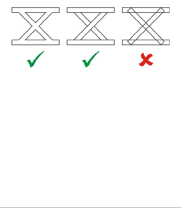
790 Corel DESIGNER X6 User Guide
Adobe Type 1 Fonts technical notes
• Adobe Type 1 fonts exported from Corel DESIGNER are unhinted.
• Each exported character constitutes a single object. Before you export multiple
objects, you must combine them by clicking Arrange Combine. You cannot
export multiple objects or grouped objects.
• For best results, avoid intersecting lines. Any object in your character should lie
completely inside or outside of others, as shown in the following example.
Left to right: three objects correctly combined; five objects correctly combined;
five objects incorrectly combined
• Fill and outline attributes applied to objects are not exported.
• Adobe Type 1 fonts you create are compatible with Adobe Type Manager version
2.0, but not with earlier versions.
Windows Bitmap (BMP)
The Windows® bitmap (BMP) file format was developed as a standard for representing
graphic images as bitmaps on the Windows operating system.
To import a bitmap file
1Click File Import.
2Locate the folder in which the file is stored.
3Do one of the following:

Supported file formats 791
• (Windows 7 and Windows 8) Choose BMP - Windows bitmap (*.bmp; *.dib;
*.rle) from the list box next to the File name box.
• (Windows XP) Choose BMP - Windows bitmap from the Files of type list box.
4Click the filename.
5Click Import.
6Click the drawing page.
To export a bitmap file
1Click File Export.
2Locate the folder in which you want to save the file.
3Choose BMP - Windows bitmap from the Save as type list box.
4Type a filename in the File name list box.
5Click Export.
6In the Convert to bitmap dialog box, adjust the width, height, resolution, color
mode, or any of the other settings.
Windows Bitmap (BMP) technical notes
Importing a BMP file
• You can import Windows Bitmap files conforming to the Windows and OS/2 BMP
specifications.
• Windows Bitmap files may be black-and-white, 16 colors, grayscale, paletted, or
RGB color (24-bit), and print accordingly, depending on your printer.
• Run-length encoding (RLE) compression may be used on all bitmaps, except RGB
color (24-bit), and black-and-white bitmaps.
• The resolution ranges from 72 to 300 dpi, or higher if you choose custom settings.
• The maximum image size is 64,535 64,535 pixels.
Exporting a BMP file
• Because raster images such as bitmaps are mapped pixel by pixel to the page, the
resolution does not increase. Instead, your bitmap appears jagged, with an
apparent loss of resolution.

792 Corel DESIGNER X6 User Guide
OS/2 Bitmap (BMP)
This type of bitmap file is designed for the OS/2 operating system. The OS/2 Bitmap
file format supports a maximum image size of 64,535 64,535 pixels. OS/2 uses Run-
length encoding (RLE) compression.
OS/2 Bitmap (BMP) technical notes
• Corel programs support Standard Version 1.3 and Enhanced Version 2.0, or later
versions of the OS/2 Bitmap file format.
• Corel programs support the following color depths when importing and exporting
BMP files: 1-bit black and white, 256 shade (8-bit) grayscale, 16-color (4-bit) and
256-color (8-bit) paletted, and 24-bit RGB.
Computer Graphics Metafile (CGM)
Computer Graphics Metafile (CGM) is an open, platform-independent metafile format
used for storing and exchanging two-dimensional graphics. It supports RGB color.
CGM files can contain both vector graphics and bitmaps, but they usually contain one
graphic type or the other — rarely both.
Corel DESIGNER supports CGM Version 1, CGM Version 3, and three CGM Version
4 profiles — ACGM, WebCGM, S1000D, and GREX. The CGM Version 4 profiles are
subsets of the CGM standard; each profile contains some CGM features. Files of these
profiles allow associating of non-graphical data with graphical elements, and are often
referred to as “intelligent graphics.” Below is a short description of the supported
Version 4 profiles:
•ACGM (ActiveCGM) — supports hyperlinking of both vector graphics and
bitmaps, zooming, panning, hotspots, and database links. It is very suitable for
displaying 2D drawings on the Internet.
•WebCGM (Versions 1.0, 2.0, and 2.1) — a binary file format that supports
hyperlinks, document navigation, picture structuring and layers, as well as
searching on WebCGM picture contents. It also supports Unicode and Web fonts.
The WebCGM profile is used widely in Web electronic documents.
•WebCGM S1000D Profile — a standard that specifies requirements for creating
graphics that are compliant with S1000D. S1000D is an international, SGML/
XML-based standard for creating and managing technical publications. It was
originally developed by the Aerospace and Defense Industries Association of
Europe (ASD) for creating technical publications for military aircrafts. The

Supported file formats 793
standard has since been modified and is now supported by numerous industries for
creating technical publications.
•GREX (ATA GREXCHANGE) — very similar to WebCGM in its rules for
graphical elements. Unlike WebCGM, this profile supports only Western encoding
and some base fonts. Although it does not support URL links, it does support
references that can be externally resolved. The GREX profile is widely used in the
automotive, aerospace, and defence industries.
To import a CGM file
1Click File Import.
2Locate the folder in which the file is stored.
3Do one of the following:
• (Windows 7 and Windows 8) Choose CGM - Computer Graphics Metafile
(*.cgm) from the list box next to the File name box.
• (Windows XP) Choose CGM - Computer Graphics Metafile from the Files of
type list box.
4Click the filename.
5Click Import.
To export a CGM file
1Click File Export.
2Locate the folder in which you want to save the file.
3Choose CGM - Computer Graphics Metafile from the Save as type list box.
4Type a filename in the File name list box.
5Click Export.
6In the CGM export dialog box, choose a version from the Export version list box.
If the version you selected supports text encoding, enable one of the following
encoding options:
• Te x t
• Binary
Choose an encoding type from the Ty p e list box.

794 Corel DESIGNER X6 User Guide
Computer Graphics Metafile (CGM) technical notes
Importing a CGM file
• Corel DESIGNER can import CGM Version 1, 3 and 4 files. Version 4 files include
WebCGM 1.0, 2.0, 2.1, and S1000D files.
• The CGM filter accepts only markers supported by the CGM file format standard.
Private-use markers are ignored.
• Text is editable, provided the file is exported from the source program with the
correct text options specified. The typeface you see may not correspond to the one
used in the source program; however, you can easily correct the typeface in the
Corel program.
• If the CGM file contains a font that is not on your computer, the PANOSE font-
matching dialog box lets you replace the font with an available one.
• When you import a CGM file, some object types are converted to
Corel DESIGNER objects. For example, hyperbolic and parabolic elements are
converted to Bézier curves.
• When you import a WebCGM (Version 2.0 and 2.1) or WebCGM S1000D file in
Corel DESIGNER, objects attributes stored in an XML companion file (XCF) are
imported.
Exporting a CGM file
• Corel DESIGNER can export version 1, 3, and 4 CGM and WebCGM 1.0 files.
• When you export to the WebCGM format, you choose from three Text encoding
options: UTF-8, UTF-16, and ISO 8859-1.
• You can export WebCGM (Version 2.0 and 2.1) or S1000D CGM files with objects
attributes stored in an XML companion file (XCF).
• You have the option of compressing WebCGM 2.1 files on export.
• CGM files can be saved in text or binary format. Text-encoded files can be opened
in an ASCII text editor.
• PostScript textures are converted to curves.
CorelDRAW (CDR)
CorelDRAW (CDR) files are primarily vector graphic drawings. Vectors define a picture
as a list of graphic primitives (rectangles, lines, text, arcs, and ellipses). Vectors are
mapped point by point to the page, so if you reduce or increase the size of a vector
graphic, the original image will not be distorted.

Supported file formats 795
Vector graphics are created and edited in graphics design applications, such as
CorelDRAW, but you can also edit vector graphics in image-editing applications such
as Corel PHOTO-PAINT. You can use vector images of various formats in desktop
publishing programs.
To import a CorelDRAW file
1Click File Import.
2Locate the folder in which the file is stored.
3Do one of the following:
• (Windows 7 and Windows 8) Choose CDR - CorelDRAW (*.cdr) from the list
box next to the File name box.
• (Windows XP) Choose CDR - CorelDRAW from the Files of type list box.
4Click the filename.
5Click Import.
6Click the drawing page.
CorelDRAW (CDR) technical notes
• Imported CorelDRAW files appear as a group of objects. Click
Arrange Ungroup to manipulate individual objects in the imported graphic.
Corel Presentation Exchange (CMX)
Corel Presentation Exchange (CMX) is a metafile format that supports bitmap and
vector information and the full range of PANTONE, RGB, and CMYK colors. Files
saved in CMX format can be opened and edited in other Corel applications.
To import a Corel Presentation Exchange file
1Click File Import.
2Locate the folder in which the file is stored.
3Do one of the following:
• (Windows 7 and Windows 8) Choose CMX - Corel Presentation Exchange
(*.cmx) from the list box next to the File name box.
• (Windows XP) Choose CMX - Corel Presentation Exchange from the Files of
type list box.

796 Corel DESIGNER X6 User Guide
4Click the filename.
5Click Import.
6Click the drawing page.
To export a Corel Presentation Exchange file
1Click File Export.
2Locate the folder in which you want to save the file.
3Choose CMX - Corel Presentation Exchange from the Save as type list box.
4Type a filename in the File name list box.
5Click Export.
Corel Presentation Exchange (CMX) technical notes
• The following versions are supported: 5, 6, 7, 8, 9, 10, 11, 12, X3, X4, X5, and
X6.
• Corel DESIGNER imports Corel Presentation Exchange (CMX) files as bitmaps.
• When you import a CMX file from an earlier version, any text color backgrounds
included in the file are not preserved.
Corel PHOTO-PAINT (CPT)
Files saved to the Corel PHOTO-PAINT (CPT) file format are bitmaps that represent
shapes as pixels arranged to form an image. When you save a graphic to the
Corel PHOTO-PAINT format, masks, floating objects, and lenses are saved with the
image. Corel DESIGNER can import and export files in Corel PHOTO-PAINT
format, including files that contain color and grayscale information.
To export a Corel PHOTO-PAINT file
1Click File Export.
2Locate the folder in which you want to save the file.
3Choose CPT - Corel PHOTO-PAINT image from the Save as type list box.
4Type a filename in the File name list box.
5Click Export.

Supported file formats 797
6In the Convert to bitmap dialog box, adjust the width, height, resolution, color
mode, or any of the other settings.
You can export Corel DESIGNER layers as objects in the CPT file format.
You can export to an image with transparent background.
Corel PHOTO-PAINT (CPT) technical notes
• This filter is available in Corel DESIGNER.
• Corel PHOTO-PAINT files may be black-and-white, grayscale, paletted, CMYK
color (32-bit), RGB color (24-bit), or Lab.
Corel Symbol Library (CSL)
Corel Symbol Library (CSL) files store symbols that can be used in other files.
Corel Symbol Library (CSL) files can be stored locally or on a network, allowing easy
deployment and management of symbol collections.
For more information, see “Managing collections and libraries” on page 281.
Cursor Resource (CUR)
The Windows® 3.x/NT Cursor Resource (.cur files) file format is used to create cursors
for Windows® 3.1, Windows® NT, and Windows® 95 interfaces. It supports cursor
graphic elements that are used in Windows pointers. You can select a color for
Transparent and Inverse masks.
The Windows 3.x/NT Cursor Resource file format supports a maximum image size of
32 32 pixels.
Cursor Resource (CUR) technical notes
• Corel programs support the following color depths when importing .cur files: 1-bit
black-and-white, 16-color (4-bit) paletted, and 256-color (8-bit) paletted.
Microsoft Word (DOC, DOCX, or RTF)
You can import the following Microsoft Word files:

798 Corel DESIGNER X6 User Guide
• Microsoft Word Document (DOC) files from versions 97, 2000, 2002, and 2003.
In addition, files saved as DOC from MS Word 2007 and 2010.
• Microsoft Word Open XML Document (DOCX) files. This file format is based on
Open XML and uses ZIP compression. It was introduced with Microsoft Word
2007.
• Rich Text Format (RTF) files. Rich Text Format (RTF) is a text format that stores
plain text and text formatting, such as bold. When you import an RTF file to
Corel DESIGNER, the text and any embedded Windows Metafile Format (WMF)
graphics are transferred. However, graphic elements are not transferred in an RTF
file exported from Corel DESIGNER.
Because Microsoft Word is a proprietary file format, it’s sometimes difficult to precisely
import all aspects of a Microsoft Word file in Corel DESIGNER. To successfully import
text with fewer inconsistencies, it is recommended that you install the Microsoft Office
Compatibility Pack. If the Microsoft Office Compatibility Pack was not previously
installed on your computer, you will be prompted to install it when you attempt to
import text.
To import a Microsoft Word file
1Click File Import.
2Do one of the following:
• (Windows 7 and Windows 8) Choose DOC, DOCX - MS Word or RTF - Rich
Te x t Fo r m a t from the All file formats list box.
• (Windows XP) Choose DOC, DOCX - MS Word or RTF - Rich Text Format
from the Files of type list box.
3Choose the drive and folder where the file is stored.
4Click the filename.
5Click Import.
If the Microsoft Office Compatibility Pack was not previously installed on your
computer, the Install compatibility pack dialog box appears. The installation of
the Microsoft Office Compatibility Pack is highly recommended. To proceed with
the installation, click Ok and follow the instructions in the installation wizard.
6In the Importing/Pasting text dialog box, you can choose to maintain or discard
text formatting. You can also choose to import tables as tables or text.
7Position the import cursor in the drawing window, and click.

Supported file formats 799
Any embedded Windows Metafile Format (WMF) or Enhanced Metafile
Format (EMF) graphics are preserved in the imported file. If the file contains
other graphic elements, these are lost during conversion and do not appear in
Corel DESIGNER.
You can place your imported text by dragging a marquee to define a paragraph
text box, or by pressing the Spacebar to place the imported text in the default
location.
If you import text and choose not to install the Microsoft Office Compatibility
Pack, the Install compatibility pack dialog box will reappear the next time
you import text, unless you enable the Do not ask me this question again
check box. You can reactivate the Install compatibility pack dialog box by
clicking To o l s Options. In the list of categories, double-clicking
Wor k sp ace , clicking Warn in g s, and enabling the Install Compatibility
Pack for DOC and DOCX check box from the Show warnings when list
box.
To export a Microsoft Word file
1Open a drawing that contains a text object.
2Click File Export.
3Choose DOC - MS Word for Windows 6/7 or RTF - Rich Text Format from the
Save as type list box.
4Type a filename in the File name list box.
5Click Export.
The filename extension for the format you choose is appended to the filename
automatically.
Only text in drawings can be exported to the Microsoft Word file formats.
Other graphical elements, such as lines, curves, and rectangles, are lost during
conversion and do not display in the file. To export graphics, use a graphic
format such as WMF.

800 Corel DESIGNER X6 User Guide
Microsoft Word (DOC, DOCX, and RTF) technical notes
Importing a DOC, DOCX, and RTF file
• To successfully import text with fewer inconsistencies, it is recommended that you
install the Microsoft Office Compatibility Pack. If the Microsoft Office
Compatibility Pack was not previously installed on your computer, you will be
prompted to install it when you attempt to import text.
• The following Microsoft Word versions are supported: Microsoft Word 97-2007,
Microsoft Word for Windows 6/7, Microsoft Word for Windows 2.x, Microsoft
Word 3.0, 4.0, 5.0, and 5.5.
• The embedded-field method for building indexes in Microsoft Word is supported,
but the style-implied method for building indexes is not.
• The Corel program matches the fonts in the file you are importing with the same or
similar fonts, depending on the fonts installed on your computer. However, the
Normal text style in Microsoft Word is converted to the default text style. To set
the default text style, click To o l s Options. In the list of categories, double-click
Document, enable the Save options as defaults for new document check box,
and then enable the Styles check box.
• Whenever possible, the program automatically converts characters available in the
sets “Symbol” or “MS Linedraw” to the corresponding Windows character set
entries.
• Most fonts are proportionally spaced, and text is reflowed when imported. As a
result, soft line and page breaks often appear in new locations if you are converting
to a fixed-pitch or nonscalable font.
• When you import text, the page size in the original document is ignored. The text
is adjusted to fit the current page size, which may affect the placement of text.
• If a table is longer then the current page, the table data continues down and off the
page.
• Nested tables are not fully supported. The text within a nested table appears within
the text box of the top-level table cell as text only (no bounding lines).
• Nested bullets are not fully supported.
• Objects and graphs are not supported.
• Equations are not maintained — the data and results may be maintained but they
are unlinked.
• Text direction is not maintained.

Supported file formats 801
Microsoft Publisher (PUB)
Microsoft® Publisher (PUB) is the native format for files created in Microsoft Publisher,
an application in the Microsoft Office line of products used for creating publications and
market materials.
Microsoft Publisher (PUB) technical notes
• Corel DESIGNER imports Microsoft Publisher files from versions 2002, 2003,
2007, and 2010.
• Exporting is not supported.
• Two-page spread is imported as separate pages.
• Master pages are not supported. A master page is imported as a separate layer on
the page. The name of the layer corresponds to the name of the master page in
Microsoft Publisher.
• Headers and footers are not supported. Text from the header/footer is placed in the
appropriate position on each page.
• Tables are supported. Not all border types are supported. If a border type is not
supported, it is replaced with an outline of the desired thickness and color.
• Border art is not supported.
• Styles are not supported. Style and formatting attributes are mapped to text.
• Some underline styles are not supported. Unsupported underline styles are replaced
with the best-match underline style available in Corel DESIGNER.
• Shadow, Emboss, and Engrave font effects are not supported.
• Horizontal rules in text objects are not supported.
• Color schemes are not supported. Color scheme colors are mapped to object colors.
• Font schemes are not supported. Font names and styles are mapped to their
equivalents in Corel DESIGNER.
• 3D shapes are supported. Surface textures are not supported.
• Word art is imported as artistic text in Corel DESIGNER. Surface textures for
extrudes are not supported.
• Linked text boxes are supported.
• Bookmarks and hyperlinks are supported.
• Form objects (Microsoft Publisher 2002) are not supported.

802 Corel DESIGNER X6 User Guide
Corel DESIGNER (DES, DSF, DS4, or DRW)
You can import Corel DESIGNER files. Files from version 10 and later have the
filename extension .des. Files from Micrografx versions 6 to 9 have the filename
extension .dsf. Version 4 files have the filename extension .ds4. The .drw filename
extension is used for a Micrografx 2.x or 3.x file. Micrografx template files (DST) are
also supported.
To import a Corel DESIGNER file
1Click File Import.
2Locate the folder in which the file is stored.
3Do one of the following:
• (Windows 7 and Windows 8) Choose DES - Corel DESIGNER (*.des) or DSF,
DRW, DST, MGX - Corel/Micrografx Designer (*.dsf; *.drw; *.ds4) from
the list box next to the File name box.
• (Windows XP) Choose DSF, DRW, DST, MGX - Corel/Micrografx Designer
or DES - Corel DESIGNER from the Files of type list box.
4Double-click the filename.
5In the Import dialog box, adjust any of the settings.
Corel DESIGNER (DSF) technical notes
• Guidelines are preserved. Grid settings are not converted, however.
• Snap points are not converted — the program preserves the default gravity
settings.
• Objects on some pages may be grouped together. You may want to select the group
and then ungroup it before editing.
• DSF files display OLE data as picture objects. OLE data object types are lost in the
conversion.
• Curvygons are converted to curves.
• Any part of a graphic that is outside the extents that Corel DESIGNER can
support cannot be accessed. You should resize the graphic before converting.
• Enhanced line styles are preserved.
• Gradient transparency may be offset in some cases.
• Hatch fills are preserved in the imported file.

Supported file formats 803
• Unclosed, filled lines are converted to two objects: one for the line and one for the
fill.
• Block text in Corel DESIGNER 9 files is converted to paragraph text in
Corel DESIGNER X6. Freeform text is converted to artistic text.
• Warped text is converted to curves.
• Repelled text (block text that wraps around an object) is converted to multiple text
objects.
• Each line of a nonrectangular text object (text placed within an object) is converted
to a separate text object.
• For block text that has many transformations, tab stops may stretch or shrink.
• Text flowing between containers is not preserved; each container is converted to a
separate object.
• Dimensions of text in small caps vary when the text is imported.
Corel DESIGNER (DES) technical notes
• Dimension lines and connector lines are converted to curves when you save a file to
an earlier version of Corel DESIGNER.
AutoCAD Drawing Database (DWG) and AutoCAD Drawing Interchange
Format (DXF)
AutoCAD Drawing Database (DWG) files are vector files used as a native format for
AutoCAD drawings.
The Drawing Interchange Format (DXF) is a tagged data representation of the
information contained in an AutoCAD drawing file. The Drawing Interchange format
is a native file format of AutoCAD. It has become a standard for exchanging CAD
drawings and is supported by many CAD applications. The Drawing Interchange
format is vector-based and supports up to 256 colors.
To import an AutoCAD Drawing Database file (DWG) or AutoCAD Drawing
Interchange Format (DXF)
1Click File Import.
2Locate the folder in which the file is stored.
3Do one of the following:

804 Corel DESIGNER X6 User Guide
• (Windows 7 and Windows 8) Choose DWG - AutoCAD (*.dwg) or DXF -
AutoCAD (*.dxf) from the list box next to the File name box.
• (Windows XP) Choose DWG - AutoCAD or DXF - AutoCAD from the Files
of type list box.
4Click the filename.
5Click Import.
6From the 3D projection list box in the Import AutoCAD file dialog box, choose
a plane projection of a three-dimensional object as seen from a given focal point.
7In the Scaling area, enable one of the following options:
• Automatic — scales the drawing using the scale of the AutoCAD source file
• English (1 unit = 1 inch) — lets you scale the drawing in inches
• Metric (1 unit = 1 mm) — lets you scale the drawing in millimeters
If you want to reduce the number of nodes on the imported object, enable the
Auto-reduce nodes check box.
8Click OK.
If the file is password protected, type the password in the Password box.
If views are specified in your file, they appear automatically in the 3D
projection list box.
If your computer is missing a font that is included in a file you are importing,
a PANOSE font matching dialog box appears and lets you substitute the font
with a similar font.
To export an AutoCAD Drawing Database file (DWG) or an AutoCAD Drawing
Interchange file (DXF)
1Click File Export.
2Locate the folder in which you want to save the file.
3From the Save as type list box, choose one of the following options:
• DWG - AutoCAD
• DXF - AutoCAD
4Type a filename in the File name list box.
5Click Export.
6In the Export to AutoCAD dialog box, choose an AutoCAD version from the
Export version list box.

Supported file formats 805
7Choose a unit of measure from the Export units list box.
8In the Export text as area, enable one of the following options:
• Curves — lets you export text as curves
• Te x t — lets you export text as editable characters
9In the Export bitmap as area, enable one of the options to export the bitmaps in a
drawing to a supported bitmap format.
10 In the Fill unmapped fills area, enable one of the following options:
• Color — fills all unmapped fills with color. To change the color, click the Color
picker and choose a color on the palette.
• Unfilled — leaves unmapped fills unfilled
AutoCAD Data Interchange Format (DXF) technical notes
• The program supports AutoCAD files from version R2.5 to 2013.
• Layers are retained on import and export.
Importing an AutoCAD DXF file
• If a DXF file is too complex to import into Corel DESIGNER, you can configure
your AutoCAD output device as an HP7475 plotter and perform a plot-to-file of
the drawing. Then you should be able to import this plot file using the import
filter. Newer versions of AutoCAD allow you to create EPS files.
• Corel graphics programs try to center the imported image. The image is scaled
down if the coordinates are larger than the maximum page size available in
Corel DESIGNER — 150 150 feet.
• Model space pages are imported as master pages.
• Solid and trace entities are filled.
• Dimension lines are imported as curves, not as dimension objects.
• A point is imported as an ellipse of minimum size.
• Files exported as “Entities only” may not appear as expected in the Corel program
because of a lack of header information.
• Imported AutoCAD files that contain formatted paragraph text preserve text
formatting such as spacing, alignment, and indents.
• Justification of text entries may not be preserved, especially if fonts are replaced in
the imported files. For best results, avoid justification of text.
• If the DXF file contains a font that is not on the user’s computer, the PANOSE
font matching dialog box lets the user replace the font with an available one.

806 Corel DESIGNER X6 User Guide
• Lines with a number of points that exceed the maximum supported in
Corel DESIGNER will be broken into multiple lines, and their fills will be
dropped.
• 3D solids are not directly supported in Corel DESIGNER. Users can import 3D
solids with the 3D Import program.
Exporting an AutoCAD DXF file
• Corel DESIGNER saves drawings in a vector format accepted by computer-aided
design/computer-aided manufacturing (CAD/CAM) programs and devices, such as
AutoCAD and certain computer-driven sign and glass cutters.
• Password protection is not available in the exported files.
• Only the outlines of objects are exported.
• Filled objects with no outlines have an outline appended to them on export.
• All text is exported by using a generic font. Text formatting is not preserved.
AutoCAD Drawing Database (DWG) technical notes
• Corel DESIGNER can import AutoCAD files from version R2.5 to 2013 and
export AutoCAD files from version R2.5 to 2013.
• If the DWG file contains a font that is not on your computer, the PANOSE font
matching dialog box lets you replace the font with an available one.
• Password protection is not available in the exported files.
Encapsulated PostScript (EPS)
EPS files can contain text, vector graphics, and bitmaps and are intended to be included
(encapsulated) in other documents. Unlike other PostScript files, which can contain
multiple pages, an EPS file is always a single page.
EPS files usually contain a preview image (header) that lets you view the file content
without the help of a PostScript interpreter. An EPS file without a preview image is
displayed as a gray box in Corel applications.
You can import and export EPS files. You can import an EPS file as a group of editable
objects as you would import any other PostScript (PS) file. You can also bring the file as
encapsulated, placing the preview image in the drawing window. The preview image is
linked to the file. It is recommended that you import an EPS file as encapsulated in the
following situations:

Supported file formats 807
• You want text in the EPS file to be displayed with the original fonts, without any
font substitutions.
• You are working with a large EPS file, and you don’t want to slow down the
application.
During the CorelDRAW Technical Suite X6 installation, you have the option of
installing Ghostscript®, which is an application that interprets the PostScript file
format. Ghostscript allows you to import PostScript Level 3 files. If you did not install
Ghostscript when you first installed the product, you can do so now.
To import an encapsulated PostScript file
1Click File Import.
2Locate the folder in which the file is stored.
3Do one of the following:
• (Windows 7 and Windows 8) Choose PS, EPS, PRN - PostScript (*.ps; *.eps;
*.prn) from the list box next to the File name box.
• (Windows XP) Choose PS, EPS, PRN - PostScript from the Files of type list
box.
4Click the filename.
5Click Import.
6In the Import EPS dialog box, enable one of the following options:
• Import as editable —brings in the file as a group of Corel DESIGNER objects
that you can modify
• Place as encapsulated PostScript —places the preview image in the drawing.
You cannot modify specific parts of the file, but you can edit the file as a whole by
applying transformations, such as sizing and rotation.
7If you are importing the file as editable, enable one of the following text options:
• Te x t — preserves text objects in the imported file so that you can edit the text
• Curves — converts text to curves
8Click OK.
9Click the drawing page.
Some restrictions apply when you modify EPS files imported as editable. For
more information, see “PostScript (PS or PRN) technical notes” on page 814.

808 Corel DESIGNER X6 User Guide
If the EPS file contains text converted to curves, the text in the imported file is
not editable, even if you choose to import the text as text.
You can also drag an EPS file from Windows Explorer into the drawing
window.
To export an encapsulated PostScript file
1Click File Export.
2Locate the folder in which you want to save the file.
3Choose EPS - Encapsulated PostScript from the Save as type list box.
4Type a filename in the File name list box.
5Click Export.
6In the EPS export dialog box, adjust any of the settings.
To set general exporting options
1In the EPS export dialog box, click the General tab.
2Perform one or more tasks from the following table.
To Do the following
Specify the color mode for exporting to eps In the Color management area, choose an
option from the Output colors as list box:
•Native
•RGB
•CMYK
•Grayscale
If you choose the Native option, all objects
preserve the color mode in which they were
created, for example RGB, CMYK,
Grayscale, or spot.
Convert spot colors In the Color management area, enable the
Convert spot colors to check box, and
select an option from the list box.
Supported file formats 809
Objects are always output as CMYK. Bitmaps have the option of different
color modes.
If you choose the 8-bit TIFF format for previewing images, you can make the
background of the bitmap transparent by enabling the Transparent
background check box in the Preview image area.
To set advanced exporting options
1In the EPS export dialog box, click the Advanced tab.
2Perform one or more tasks from the following table.
Choose a file format for previewing the
PostScript image
In the Preview image area, choose one of
the following options:
•None
•TIFF
•WMF
If you choose the TIFF format, choose a color
mode and resolution.
Specify how to export text Enable one of the following options in the
Export text as area:
•Curves — lets you export text as curves
•Te x t — lets you export text as editable
characters
If you want to include PostScript font
information with your file, enable the
Include fonts check box.
Choose a compatibility option From the Compatibility list box, choose a
PostScript level that is supported by the
printer or the application with which you
will be printing or displaying the file.
To Do the following
Specify the author’s name Type a name in the Author box.
To Do the following

810 Corel DESIGNER X6 User Guide
Apply bitmap compression In the Bitmap compression area, enable
the Use JPEG compression check box.
Move the JPEG quality slider to adjust the
quality of the bitmaps.
Apply a trapping option In the Tr a p p i n g area, enable any of the
following options:
•Preserve document overprint settings
— maintains current settings on objects
•Always overprint black — creates a color
trap by causing any objects that contain
at least 95 percent black to overprint any
underlying objects
•Auto-spreading — creates a color trap by
assigning an outline to an object that is
the same color as its fill and having it
overprint underlying objects
•Maximum — lets you specify the amount
of spread that the Auto-spreading option
assigns to an object
If you want to specify the minimum font size
to which Auto-Spreading is applied, type a
value in the Text above box.
If you want the outlines of all objects on the
page to have the same width, enable the
Fixed width check box.
To Do the following
Supported file formats 811
The Use JPEG compression check box remains disabled until you choose a
PostScript level that supports this feature.
To install Ghostscript
1Close any open programs.
2On the Windows taskbar, click Start Control panel.
3Do one of the following:
• In Windows 7 or Windows 8, click Uninstall a program.
• In Windows XP, click the Add or remove programs icon.
4Do one of the following:
• In Windows 7 or Windows 8, double-click CorelDRAW Technical Suite X6 from
the Uninstall or change a program page.
• In Windows XP, choose CorelDRAW Technical Suite X6 from the Currently
installed programs list.
5Click Modify.
6Click the Features tab.
Apply a bounding box In the Bounding box area, enable any of
the following options:
•Objects — aligns the bounding box
exactly to the objects in the file
•Page — aligns the bounding box to the
page
•Bleed limit — lets you specify how far the
bleed extends beyond the edge of the area
to be printed
•Crop marks — lets you use crop marks as
alignment aids when you trim the print
output to its final size
•Floating point numbers — lets you use
numbers with decimals
Maintain OPI link Enable the Maintain OPI links check box
to use low-resolution images as placeholders
for high-resolution images.
To Do the following

812 Corel DESIGNER X6 User Guide
7Enable the GPL Ghostscript check box.
8Follow the instructions in the installation wizard.
Encapsulated PostScript (EPS) technical notes
Importing an EPS file
• If the encapsulated PostScript file was imported with the Place as Encapsulated
PostScript option, and if it contains a preview image (called a header), the preview
image is imported and displayed. The EPS information remains attached to the
header and is used when the image is printed to a PostScript printer.
• The PostScript Interpreted filter converts the objects in the encapsulated PostScript
file to native Corel DESIGNER objects on import.
• When you import a file with large or complex gradient fills, you may generate a
large number of objects.
Exporting an EPS file
• On a PostScript printer, graphics exported to the encapsulated PostScript (EPS)
format print from other programs exactly as they do from a Corel graphics
programs.
• You can save a header to the Tagged Image file format (TIFF) or Windows Metafile
format (WMF) in black and white, 4-bit grayscale or color, or 8-bit grayscale or
color. You can set the header resolution between 1 and 300 dots per inch (dpi); the
default header resolution is 72 dpi. If the program importing the EPS file has a
limitation on the image header size, you might receive an error message stating
that the file is too large. To reduce file size, in the EPS export dialog box, choose
Black and White from the Mode box, and lower the header resolution before
exporting the file. The setting determines only the resolution of the header and has
no impact on the print quality of a drawing. Color headers are useful for viewing
EPS files. If the program in which you are going to use the file does not support
color headers, try exporting with a mono header instead. You can also export
without a header.
• Along with the graphic, exported EPS files contain a filename, program name, and
date.
• To save font information in an EPS file, enable the Include fonts check box in the
Export text as area.
• If you export text as curves, text is converted to vector curves.

Supported file formats 813
• If a font used in the file is not available on the printer or has not been saved in the
file, either the text is printed in Courier font or the drawing is not printed.
PostScript (PS or PRN)
PostScript (PS) files use PostScript language to describe the layout of text, vector
graphics, or bitmaps for printing and display purposes. They can contain multiple
pages. PostScript files are imported as a group of objects that you can edit.
PostScript files usually have a .ps filename extension, but you can also import PostScript
files with a .prn extension. Files with a .prn filename extension, commonly known as
Printer (PRN) files, contain instructions about how a file should be printed. These files
let you reprint a document even if the application in which the document was created
is not installed on your computer.
During the CorelDRAW Technical Suite X6 installation, you have the option of
installing Ghostscript, which is an application that interprets the PostScript file format.
Ghostscript assists the file importing process. If you did not install Ghostscript during
the installation, see “To install Ghostscript” on page 811.
You can also import encapsulated PostScript (EPS) files. For more information, see
“Encapsulated PostScript (EPS)” on page 806.
To import a PostScript (PS or PRN) file
1Click File Import.
2Locate the folder in which the file is stored.
3Do one of the following:
• (Windows 7 and Windows 8) Choose PS, EPS, PRN - PostScript (*.ps; *.eps;
*.prn) from the list box next to the File name box.
• (Windows XP) Choose PS, EPS, PRN - PostScript from the Files of type list
box.
4Click the filename, and click Import.
5In the Import text as area, enable one of the following text options:
• Te x t — preserves text objects in the imported file so that you can edit the text
• Curves — converts text to curves
6Click OK.
7Click the drawing page.

814 Corel DESIGNER X6 User Guide
When the PostScript file contains text converted to curves, the text in the
imported file is not editable, even if you choose to import the text as text.
PostScript (PS or PRN) technical notes
• PostScript files containing mesh fills with spot colors, DeviceN images, or duotone
images cannot be imported. Installing Ghostscript resolves this issue.
• Mesh fills in the CMYK color mode are imported as bitmaps and cannot be edited.
• Gradient fills are imported as a group of filled objects simulating the gradient fill
appearance and cannot be edited as gradient fills.
• RGB bitmaps are converted to CMYK in imported PS files. Installing Ghostscript
resolves this issue.
• Font information is maintained only if the font was embedded in the original file
before it was imported.
• Files that are too large cannot be imported into some programs because of memory
limitations. This problem can be caused by complex gradient fills that increase the
number of objects in a graphic.
• Only Printer (PRN) files, PS files, and EPS files in PostScript format are supported.
GIF
GIF is a bitmap-based format designed for use on the Web. It is highly compressed to
minimize file transfer time and supports images with up to 256 colors. The GIF file
format supports a maximum image size of 30,000 30,000 pixels and uses LZW
compression.
The GIF format provides the ability to store multiple bitmaps in a file. When the
multiple images are displayed in rapid succession, the file is called an animated GIF file.
For Internet use, you can also save images to the JPEG and PNG formats. If you want
to publish an image to the Web and are not sure which format to use, see “Exporting
bitmaps for the Web” on page 289.
To import a GIF file
1Click File Import.
2Locate the folder in which the file is stored.
3Do one of the following:

Supported file formats 815
• (Windows 7 and Windows 8) Choose GIF - CompuServe Bitmap (*.gif) from
the list box next to the File name box.
• (Windows XP) Choose GIF - CompuServe Bitmap from the Files of type list
box.
4Click the filename.
5Click Import.
6Click the drawing page.
You can drag on the drawing page to resize the image.
GIF technical notes
• Corel programs import versions 87A and 89A of the GIF file format, but export
only to version 89A. Version 87A supports basic features and interlacing. The
newer version, 89A, includes all features found in 87A plus the ability to use
transparent colors and to include comments and other data from the image file.
• Corel programs support the following color depths when importing animated GIF
files: black and white (1-bit), 16 colors, grayscale (8-bit), and 256 color paletted (8-
bit).
HTML
HTML files are plain-text (also known as ASCII) files that can be created using any text
editor, including SimpleText and TextEdit. HTML files are intended for display on a
Web browser.
You can import HTML files to edit text and add Web objects, bookmarks, and
hyperlinks. For more information about preparing files and objects for Web publishing
and uploading to the Web, see “Exporting to HTML” on page 779.
You can also
Resample a graphic while importing For more information, see “To resample a
bitmap while importing” on page 744.
Crop a graphic while importing For more information, see “To crop a bitmap
while importing” on page 745.

816 Corel DESIGNER X6 User Guide
To import an HTML file
1Click File Import.
2Locate the folder in which the file is stored.
3Do one of the following:
• (Windows 7 and Windows 8) Choose HTM - HyperText Markup Language
(*.htm) from the list box next to the File name box.
• (Windows XP) Choose HTM - HyperText Markup Language from the Files of
type list box.
If you don’t see this option, you first need to add the HTML filter to your
installation of CorelDRAW Technical Suite X6. For information about modifying
your installation, see “To modify or repair a CorelDRAW Technical Suite
installation” on page 4.
4Click the filename.
5Click Import.
6In the Use default text colors area, enable one of the following options:
• Ye s — uses the default color for text and for visited, unvisited, and active links,
ignoring the colors specified in the HTML file
• No — uses the colors specified in the HTML file
7Click the drawing page.
HTML technical notes
Importing an HTML file
• The HTML import filter extracts editable information from a Web document and
brings objects into Corel DESIGNER in a manner similar to the original layout.
• The HTML import filter extracts editable information from a Web document and
brings objects into Corel DESIGNER in a manner similar to the original layout.
• Imported HTML files that exceed the boundaries of the drawing page continue
down the workspace without a page break.
JPEG (JPG)
JPEG is a standard format developed by the Joint Photographic Experts Group.
Through the use of superior compression techniques, this format allows the transfer of
Supported file formats 817
files among a wide variety of platforms. JPEG supports 8-bit grayscale, 24-bit RGB,
and 32-bit CMYK color modes.
The JPEG format is commonly used on the Web. For more information about exporting
to the JPEG file format, see “Exporting bitmaps for the Web” on page 289.
To import a JPEG file
1Click File Import.
2Locate the folder in which the file is stored.
3Do one of the following:
• (Windows 7 and Windows 8) Choose JPG - JPEG Bitmaps (*.jpg; *.jtf; *.jff;
*.jpeg) from the list box next to the File name box.
• (Windows XP) Choose JPG - JPEG Bitmaps from the Files of type list box.
4Click the filename.
5Click Import.
6Click the drawing page.
You can drag on the drawing page to resize the image.
JPEG technical notes
• JPEG files can contain EXIF data. This data may affect how the JPEG files open.
JPEG 2000 (JP2)
The JPEG 2000 (JP2) file format is a JPEG image with advanced compression and file
data capabilities. JPEG 2000 standard files can store more descriptive file data (or
metadata), such as dimensions, tone scale, color space, and intellectual property rights,
than JPEG 2000 codestream files. Codestream files are optimized for network
You can also
Resample a graphic while importing For more information, see “To resample a
bitmap while importing” on page 744.
Crop a graphic while importing For more information, see “To crop a bitmap
while importing” on page 745.

818 Corel DESIGNER X6 User Guide
transmission since they resist bit errors that can cause data loss on low-bandwidth
channels.
Not all Web browsers support JPEG 2000 formats. You may require a plug-in to view
these files.
When you export the image to a JP2 file, you can choose to view download progression
by resolution, quality, and position.
To import a JPEG 2000 file
1Click File Import.
2Locate the folder in which the file is stored.
3Do one of the following:
• (Windows 7 and Windows 8) Choose JP2 - JPEG 2000 Bitmaps (*.jp2; *.j2k)
from the list box next to the File name box.
• (Windows XP) Choose JP2 - JPEG 2000 Bitmaps from the Files of type list
box.
4Click the filename.
5Click Import.
6Click the drawing page.
To export a JPEG 2000 bitmap
1Click File Export.
2Choose JP2 - JPEG 2000 bitmaps from the Save as type list box.
3Ty p e a n a m e i n t h e File name box.
4Click Export.
5Choose a JPEG 2000 preset from the Preset list list box in the upper-right corner
of the dialog box.
If you want modify the preset settings, you can change the exporting options in the
dialog box.
6Click OK.
You can also
Choose a color mode In the Settings area, choose a color mode
from the Color mode list box.

Supported file formats 819
JPEG 2000 (JP2) technical notes
• Corel DESIGNER can import either JP2 or JPC files but export only to the JP2
format.
• Corel DESIGNER supports exporting JPEG 2000 files in 24-bit RGB, and 8-bit
grayscale.
• CMYK, 48-bit RGB, and black-and-white images are not supported for export.
Kodak Photo CD Image (PCD)
Kodak® Photo CD image file is a raster format developed by Eastman Kodak for
scanning photographic images onto compact discs. PCD images are derived from 35-
mm film negatives or slides that have been converted to digital format and stored on a
CD. Photo CD allows high-quality digital storage and manipulation of photographic
Embed the color profile In the Advanced area, enable the Embed
color profile check box.
Control image quality In the Settings area, choose a quality option
from the Quality list box or type a value.
Set the JPEG 2000 download from low to
high resolution so that the size of the entire
image increases
In the Advanced area, choose
Resolution\Quality from the Progression
list box.
Set the JPEG 2000 download from the
upper-left corner of the image to the lower-
right corner
In the Advanced area, choose
Resolution\Position from the Progression
list box.
Set the JPEG 2000 download from the
upper-left corner of the image to the lower-
right corner
In the Advanced area, choose Position from
the Progression list box.
Set the JPEG 2000 download progressively
by color channel
In the Advanced area, choose Channels
from the Progression list box.
Allow JPEG 2000 codestream In the Advanced area, enable the
Codestream check box.
You can also
820 Corel DESIGNER X6 User Guide
images. The PCD format is typically used by photofinishers and service bureaus who
provide the service of placing photographs on CDs.
This file format is not supported by the 64-bit version of
CorelDRAW Technical Suite X6.
To import a Kodak Photo CD image file
1Click File Import.
2Choose the folder in which the file is stored.
3Do one of the following:
• (Windows 7 and Windows 8) Choose PCD - Kodak Photo-CD image (*.pcd)
from the list box next to the File name box.
• (Windows XP) Choose PCD - Kodak Photo-CD image from the Files of type
list box.
4Click the filename.
5Click Import.
6In the PCD import dialog box, move any of the following sliders:
• Brightness — lets you set the amount of light
• Contrast — lets you specify the contrast between the pixels in the image
• Saturation — lets you specify the purity of a color
• Red — lets you specify the amount of red in the image
• Green — lets you specify the amount of green in the image
• Blue — lets you specify the amount of blue in the image
7From the Resolutions list box, choose an image size.
8From the Image type list box, choose a color mode.
9Position the import placement start cursor on the drawing window, and click.
You can drag on the drawing page to resize the image.
You can also
Resample a graphic while importing For more information, see “To resample a
bitmap while importing” on page 744.
Crop a graphic while importing For more information, see “To crop a bitmap
while importing” on page 745.

Supported file formats 821
You can remove the adjustments made by the photofinisher at the time the
original image was scanned and placed on the Photo CD disk by enabling the
Subtract scene balance check box.
You can identify out-of-gamut areas of the image by enabling the Show colors
out of gamut check box, which renders the out-of-gamut pixels in pure red or
pure blue.
Kodak Photo CD Image (PCD) technical notes
• Kodak Photo CD (PCD) images may be subject to copyright. The Corel program
does not display a warning message about this.
• Other Kodak-compatible programs may install the Kodak pcdlib.dll file in the
Windows folder instead of the Windows\System folder. This difference in the
folder location produces an error message.
•When you import Photo CD files, a dialog box appears and prompts you to choose
the desired file resolution and color. The resolution is limited to 72 dpi and the
maximum image size is 3072 2048 pixels.
• You can import the following color modes: RGB (24-bit), paletted (8-bit), and
grayscale (8-bit).
PICT (PCT)
The Macintosh PICT file format was developed for the Mac® OS platform by Apple®
Computer Inc. It is a native file format of QuickDraw® and can contain both vectors
and bitmaps. The Macintosh PICT file format is widely used in Macintosh applications.
To import a PICT file
1Click File Import.
2Locate the folder in which the file is stored.
3Do one of the following:
• (Windows 7 and Windows 8) Choose PCT - Macintosh PICT (*.pct; *.pict)
from the list box next to the File name box.
• (Windows XP) Choose PCT - Macintosh PICT from the Files of type list box.
4Click the filename.
5Click Import.
6Click the drawing page.

822 Corel DESIGNER X6 User Guide
You can drag on the drawing page to resize the image.
To export a PICT file
1Click File Export.
2Locate the folder in which you want to save the file.
3Choose PCT - Macintosh PICT from the Save as type list box.
4Type a filename in the File name list box.
5Click Export.
PICT (PCT) technical notes
• Corel graphics programs can import vector drawings and bitmaps contained in
PICT (PCT) files.
• Objects that contain a fill and an outline open as a group of two objects. One object
is the outline, and the other is the fill.
• PICT fills are often bitmap patterns, and the Corel program tries to maintain these
fills as bitmap patterns.
• Pattern outlines are converted to a solid color.
• Text in PICT files opens as editable text. If a typeface in the imported file is not
available on your computer, it is converted to the font that it most closely
resembles.
• Text alignment may not be preserved in the original file. This is due to the
differences in font size, and intercharacter and interword spacing between the two
formats. Any misalignment is easily corrected using the text formatting settings in
the program.
PaintBrush (PCX)
The PaintBrush (PCX) file format is a bitmap format originally developed by the ZSoft
Corporation for the PC Paintbrush program.
To import a PaintBrush file
1Click File Import.
2Locate the folder in which the file is stored.

Supported file formats 823
3Do one of the following:
• (Windows 7 and Windows 8) Choose PCX - PaintBrush (*.pcx) from the list
box next to the File name box.
• (Windows XP) Choose PCX - PaintBrush from the Files of type list box.
4Click the filename.
5Click Import.
6Click the drawing page.
To export a PaintBrush file
1Click File Export.
2Locate the folder in which you want to save the file.
3Choose PCX - PaintBrush from the Save as type list box.
4Type a filename in the File name list box.
5Click Export.
6In the Convert to bitmap dialog box, adjust the width, height, resolution, color
mode, or any of the other settings.
7In the Convert to paletted dialog box, adjust any of the settings.
PaintBrush (PCX) technical notes
Exporting a PCX file
• Bitmaps may be black-and-white, 16 colors, grayscale (8-bit), paletted (8-bit), or
RGB color (24-bit).
• Run-length encoding (RLE) compression is supported, and the maximum image
size is 64,535 64,535 pixels.
• These files may contain one, two, or four color planes.
• This file format is supported in Corel DESIGNER.
Importing a PCX file
• PCX files can be imported if they conform to the following PCX specifications: 2.5,
2.8, and 3.0.
• Bitmaps may be black-and-white, 16 colors, grayscale (8-bit), paletted (8-bit), or
RGB color (24-bit).
• RLE compression is supported and the maximum image size is 64,535 64,535
pixels.

824 Corel DESIGNER X6 User Guide
• These files may contain one, two, or four color planes. Files containing three color
planes or more than four color planes cannot be imported.
Adobe Portable Document Format (PDF)
The Adobe Portable Document Format (PDF) is a file format designed to preserve fonts,
images, graphics, and formatting of an original file. Using Adobe Reader and Adobe
Acrobat, a PDF file can be viewed, shared, and printed by Mac OS, Windows, and
UNIX® users.
You can open or import a PDF file. When you open a PDF file, it is opened as a
Corel DESIGNER file. When you import a PDF file, the file is imported as grouped
objects and can be placed anywhere within your current document. You can import an
entire PDF file, individual pages from the file, or multiple pages.
Some PDF files are secured by a password. You are prompted to enter a password before
you can open and edit a secured PDF file. For information about PDF security options,
see “Setting security options for PDF files” on page 768.
You can save a file in the PDF format. For more information, see “Exporting to PDF”
on page 757.
Importing text
The method by which PDF files store information affects how text looks and how easily
it can be edited. To help ensure the best results for your document, you can choose
whether to import the text in your file as text or as curves.
When you import text as text, the font and text are preserved, and the text is fully
editable as artistic or paragraph text. However, some effects and formatting may be lost.
This option is recommended if you have a PDF file that contains large blocks of text,
such as a newsletter, and you want to reformat the text or add text content.
When you import text as curves, the appearance of the text, including all effects applied
to it, are preserved, and each letter is converted to a curve object. With this option, the
text formatting features can no longer be used to edit the text. If you have a PDF file
that contains a small amount of text that does not require editing, or if you do not have
the fonts used in the PDF file, you can import the text as curves. For more information
about converting text to curves, see “Finding, editing, and converting text” on
page 469.

Supported file formats 825
Importing comments
Some PDF files can contain comments and annotations. These may consist of text,
curves, and other drawings or shapes that are added to the PDF document by a
reviewer. If commenting rights have been granted, you have the option of importing
the comments with the PDF file. When comments are imported, they are placed on a
separate “Comments” layer in the document. By default, this layer is set as non-
printable.
If the PDF document contains comments written by multiple reviewers, the comments
are grouped on the “Comments” layer based on the author’s name.
To import an Adobe Portable Document Format file
1Click File Import.
2Locate the folder in which the file is stored.
3Do one of the following:
• (Windows 7 and Windows 8) Choose PDF - Adobe Portable Document
Format or All file formats from the list box next to the File name box.
• (Windows XP) Choose PDF - Adobe Portable Document Format or All file
formats from the Files of type list box.
4Click the filename.
5Click Import.
If the file is protected by a password, type a valid password in the Password box.
6In the Import text as area, choose one of the following options:
• Te x t — lets you edit and reformat the text from the PDF file
• Curves — converts text to curves. Choose this option when you do not need to
edit the text from the PDF file, and you want to maintain the appearance of the
original text.
If you are importing a multipage document, select the pages you want to import,
and click OK.
If the document contains comments that you want to import, check the Import
comments and place on a separate layer check box.
7Click the drawing page.
If a block of text is imported as separate text objects, you can combine the text
objects by selecting them and clicking Arrange Combine.

826 Corel DESIGNER X6 User Guide
Adobe Portable Document Format (PDF) technical notes
Publishing a PDF file
• Texture fills created in Corel DESIGNER are exported and imported as bitmap
patterns.
Importing a PDF file
• Corel DESIGNER imports Adobe Portable Document Format files.
• Transparency applied to text and graphics is preserved.
• Character attributes of text, including OpenType features, are preserved.
• DeviceN color spaces may be converted to RGB or CMYK processed colors in the
imported file, depending on the file content.
• Layers are preserved in files created with Adobe Acrobat 6 and later.
• Xform objects, headers and footers are converted to symbols.
• Symbols are preserved when PDF files created with version 1.3 or later undergo
round-tripping.
• Comments are preserved and imported on a separate “Comments” layer in the
document.
• Text annotations, including free text and pop-up annotations, are imported as
paragraph text.
• Sticky Notes display as a rectangle with the appropriate background and border
color. Headers in Sticky Notes are not supported.
• Line annotations display as straight lines with the appropriate width and color.
Arrows with different fill and outline colors display fill and outline of the same
color.
• Square and circle annotations display as rectangles and ellipses with the appropriate
fill/outline properties. Polygon and polyline annotations are mapped as polycurves
with similar fill/outline properties. Cloud shapes display as polygons.
• Text markup annotations, such as highlights, underlining, and strikeouts, are
imported.
• Standard ink and stamp annotations are supported. Custom stamp annotations are
not supported.
HPGL Plotter File (PLT)
The HPGL Plotter File (PLT) format, developed by Hewlett-Packard®, is vector-based.
It is used in programs such as AutoCAD for printing drawings on plotters. Other Corel

Supported file formats 827
applications can interpret a SUBSET of the HPGL and HPGL/2 command set. This
format uses a scaling factor of 1,016 plotter units to 1 inch.
To import an HPGL Plotter file
1Click File Import.
2Locate the folder in which the file is stored.
3Do one of the following:
• (Windows 7 and Windows 8) Choose PLT - HPGL Plotter File (*.plt; *.hgl)
from the list box next to the File name box.
• (Windows XP) Choose PLT - HPGL Plotter File from the Files of type list.
4Click the filename.
5Click Import.
6In the HPGL options dialog box, adjust any of the settings.
To export an HPGL Plotter file
1Click File Export.
2Locate the folder where you want to store the file.
3Choose PLT - HPGL Plotter File from the Save as type list box.
4Type a filename in the File name list box.
5Click Export.
6In the HPGL export dialog box, adjust any of the settings.
HPGL Plotter (PLT) technical notes
Importing a PLT file
• Corel programs support versions 1 and 2 of PLT file formats although some
features of version 2 are not supported.
• You can import images larger than the Corel program’s maximum page size by
enabling the Scale option in the HPGL options dialog box, which lets you resize
the imported image.
• The curve resolution factor can be set to a value between 0.0 and 1.0 inch. The
value can be very precise; up to eight decimal places are accepted. A setting of 0.0
results in the highest resolution, but it also greatly increases file size. A curve
resolution of 0.004 inch is recommended.

828 Corel DESIGNER X6 User Guide
• The PLT file format does not contain color information. Instead, the various objects
in a PLT file have certain pen numbers associated with them. When imported into
a Corel program, each pen number is assigned a specific color. You can specify the
color assigned to a particular pen, so that you can match the original colors of the
graphic.
•The Pen selection list contains 256 pens, although not all of the pens may be
assigned. You can change the color assignments by choosing the pen and then
choosing a new color for that pen from the Pen color list box. Choosing Custom
colors brings up a color definition dialog box that allows you to define a custom
color according to RGB values.
• You can change the pen width assignments by choosing the pen and then choosing
a new width for that pen from the Pen width list box.
• You can change the pen velocity by choosing the pen and then choosing a new
velocity for that pen from the Pen velocity list box. This is useful only for
exporting PLT files.
• You can set a defined pen to the Unused option. You can also reset the current Pen
Library pen settings to the previously saved settings.
• Corel programs support numerous dotted, dashed, and solid line types of the PLT
file format. The pattern number of a line in a PLT file is translated to a line type
pattern.
• If the PLT file contains a font that is not on the user’s computer, the PANOSE font
matching dialog box lets the user replace the font with an available one.
Exporting a PLT file
• In Corel DESIGNER X6, you have the option of setting the Plotter origin to To p
left.
• Only the outlines of objects are exported to the PLT file format.
• Dotted lines, dashed lines, and arrowheads are mapped to standard line types of the
PLT file format.
• Bézier curves are converted to line segments.
• Outline thickness and calligraphic settings are lost.
• Outline colors are limited to eight: black, blue, red, green, magenta, yellow, cyan,
and brown.

Supported file formats 829
Portable Network Graphics (PNG)
The Portable Network Graphics (PNG) file format is an excellent file format for lossless,
portable, and well-compressed storage of bitmaps. It takes up a minimum amount of
disk space and can be easily read and exchanged between computers. The Portable
Network Graphics format provides a replacement for the GIF format and can also
replace many common uses of the TIFF format.
The Portable Network Graphics format is designed to work well in online viewing, such
as on the Web, and it’s fully streamable with a progressive display option. Some Web
browsers do not support all formatting and features. You can export images to the
Portable Network Graphics file format if you want to use transparent backgrounds,
image interlacing, image maps, or animation in your Web pages.
Exporting graphics to the Portable Network Graphics format converts them to bitmaps
that can be used in desktop publishing programs and Microsoft Office applications. You
can also edit Portable Network Graphics in image-editing programs such as
Corel PHOTO-PAINT and Adobe Photoshop. For more information, see “Exporting
bitmaps for the Web” on page 289.
You can also save images to the GIF and JPEG formats to use on the Internet. If you
want to publish an image to the Web but are not sure which format to use, see
“Exporting bitmaps for the Web” on page 289.
To import a Portable Network Graphics file
1Click File Import.
2Locate the folder in which the file is stored.
3Do one of the following:
• (Windows 7 and Windows 8) Choose PNG - Portable Network Graphics
(*.png) from the list box next to the File name box.
• (Windows XP) Choose PNG - Portable Network Graphics from the Files of
type list box.
4Click the filename.
5Click Import.
6Click the drawing page.

830 Corel DESIGNER X6 User Guide
You can drag on the drawing page to resize the image.
Portable Network Graphics (PNG) technical notes
• You can import Portable Networks Graphics (PNG) files from 1-bit black and
white to 24-bit color; 48-bit color is not supported.
• Masks and indexed-color, grayscale, and true color images are supported. Masks,
however, are not saved in 1-bit black-and-white or 8-bit paletted files.
• LZ77 compression is supported, and the maximum image size is 30,000 30,000
pixels. Sample depths range from 1 to 16 bits.
• The PNG file format also checks full-file integrity and detects common
transmission errors. The PNG file format can store gamma and chromatic data for
improved color matching on different platforms.
Adobe Photoshop (PSD)
The Adobe Photoshop (PSD) file format is the native bitmap file format for Adobe
Photoshop.
To import an Adobe Photoshop file
1Click File Import.
2Locate the folder in which the file is stored.
3Do one of the following:
• (Windows 7 and Windows 8) Choose PSD - Adobe Photoshop (*.psd; *.pdd)
from the list box next to the File name box.
• (Windows XP) Choose PSD - Adobe Photoshop from the Files of type list
box.
4Click the filename.
You can also
Resample a graphic while importing For more information, see “To resample a
bitmap while importing” on page 744.
Crop a graphic while importing For more information, see “To crop a bitmap
while importing” on page 745.

Supported file formats 831
5Click Import.
6Click the drawing page.
To export an Adobe Photoshop file
1Click File Export.
2Locate the folder in which you want to save the file.
3Choose PSD - Adobe Photoshop from the Save as type list box.
4Type a filename in the File name list box.
5Click Export.
6In Convert to bitmap dialog box, adjust the width, height, resolution, color mode,
or any of the other settings.
You can export to an image with a transparent background.
Adobe Photoshop (PSD) technical notes
Importing a PSD file
• Monotone, grayscale, duotone, 48-bit RGB, and up to 32-bit CMYK images are
supported.
• Some layer effects cannot be imported. (Gradient map adjustment layer is imported
without Noise, Opacity stops, and Dither.)
• Imported layers using the Darken Color and Lighten Color blend modes map to
the If Darker and If Lighter merge modes, respectively. For more information about
working with merge modes, see “Applying merge modes” on page 442.
• Files that contain spot color channels are imported as multichannel (DeviceN)
bitmaps.
You can also
Resample a graphic while importing For more information, see “To resample a
bitmap while importing” on page 744.
Crop a graphic while importing For more information, see “To crop a bitmap
while importing” on page 745.

832 Corel DESIGNER X6 User Guide
Exporting a PSD file
• This format supports 1-bit black-and-white and up to 32-bit CMYK color images.
• Layers are supported.
• Text is rasterized.
• Spot color channel information is preserved in the exported file.
Corel Painter (RIF)
Imported Corel Painter (RIF) files retain information such as floating objects, which
makes the files much larger than GIF or JPEG files. Corel Painter files can be imported
for resizing and adjusting floaters.
To import a Corel Painter file
1Click File Import.
2Locate the folder in which the file is stored.
3Do one of the following:
• (Windows 7 and Windows 8) Choose RIFF - Painter (*.rif) from the list box
next to the File name box.
• (Windows XP) Choose RIFF - Painter from the Files of type list box.
4Click the filename.
5Click Import.
6Click the drawing page.
Corel Painter (RIF) technical notes
• The embedded color profile is preserved, but can be changed after importing the
file.
• If the Corel Painter image contains a transparent background, which is called a
canvas in Corel Painter, it is preserved.
You can also
Resample a graphic while importing For more information, see “To resample a
bitmap while importing” on page 744.
Crop a graphic while importing For more information, see “To crop a bitmap
while importing” on page 745.

Supported file formats 833
• Vector shapes are not preserved in the imported file.
• Text and annotations are not preserved.
• Bitmap layers are imported as grouped objects.
• Liquid Ink, Watercolor, Digital Watercolor, and plug-in layers are imported as
RGB objects.
• Mosaics and tesselations are imported as RGB objects.
• Image slicing is not retained.
Scalable Vector Graphics (SVG)
Scalable Vector Graphics (SVG) is an open standard graphics file format that allows
designers to put the power of vector graphics to work on the Web. It was created by the
World Wide Web Consortium (W3C®).
SVG files are described in Extensible Markup Language (XML). They are vector graphic
images, which can provide superior detail and faster download times than bitmaps.
Compressed SVG files have an .svgz filename extension.
To view SVG files, you need an SVG viewer plug-in such as the Corel SVG viewer.
Unicode support
SVG files support Unicode encoding for text. When exporting an SVG file, you can
choose a Unicode encoding method.
Embedding and linking
You can embed information in an SVG file, or you can create additional files to store
some of the information. For example, you can embed a style sheet in an SVG file, or
you can create an external cascading style sheet and link it to the SVG file. By default,
JavaScript, such as JavaScript related to rollovers, is embedded in the exported file, but
you can choose to store it as a separate file linked to the SVG file. Also, you can embed
bitmaps, or you can save bitmaps as externally linked files.
Exporting text
You can export text as text or curves. When exporting text as text, you can choose to
embed all fonts in a Scalable Vector Graphics file to have full editing capabilities. You
can also embed only the fonts used, and common English or common Roman fonts.

834 Corel DESIGNER X6 User Guide
Using preset export options
To make your work easier, you can use preset export options, and you can create custom
preset export options that you can reuse later.
Using SVG colors
SVG colors correspond to color keywords. You can use the SVG color palette available
in the application to help ensure that colors in the exported SVG file are defined by color
keywords. To ensure that the SVG color names you choose are retained in the SVG
exported file, it is recommended that you disable color correction. For information
about color correction, see “Getting started with color management in
Corel DESIGNER” on page 391.
Adding reference information to SVG objects
Reference information can be added and retained in an exported Scalable Vector
Graphics object. You can add information to an object so that the information appears
in the file’s XML tags. These tags are derived from the data field names, each of which
is formatted as general text, data and time, linear and angular dimensions, or numbers.
For example, you can name individual objects in the drawing and add comments for
each of these objects. The name and comments for each object display in the tags of the
exported Scalable Vector Graphics file.
To export a Scalable Vector Graphics file
1Click File Export.
2Locate the folder in which you want to save the file.
3Choose SVG - Scalable vector graphics or SVGZ - Compressed SVG from the
Save as type list box.
4Type a filename in the File name list box.
5Click Export.
6From the Compatibility list box, choose an SVG version for the exported file.
7From the Encoding method list box, choose one of the following encoding
options:
• Unicode - UTF-8 — produces a smaller file size. This is the default encoding
method and is useful in most circumstances.
• Unicode - UTF-16 — produces a bigger file size
8In the Export text area, enable one of the following options:
Supported file formats 835
• As text — exports text as editable characters, known as glyphs
• As curves — exports text as curves
9Choose one of the following options from the Styling options list box:
• Presentation attributes — lets you specify attributes directly in an element in
the exported file
• Internal style sheet — uses the CLASS attribute to embed the style sheet in the
Scalable Vector Graphics file
• External CSS — creates an external cascading style sheet file and links it to the
Scalable Vector Graphics file
JavaScript related to rollovers can be saved to a separate file by enabling the Link
externally check box in the JavaScript area.
You can also
Embed a font Enable the Embed font in file check box.
Choose which fonts you want to embed from
the Character subsetting list box.
Give an embedded font priority over the
default browser font
Enable the Give embedded font priority
check box.
Set the drawing precision From the Drawing precision list box, select
the drawing precision defined as a ratio of
units.
Set the number of fountain fill steps to
export
In the Fountain steps box, type the number
of fill levels.
Export bitmaps to the JPEG, GIF, or PNG
file format
Choose a bitmap format from the Bitmap
export type list box, and enable one of the
following options:
•Link images — saves each bitmap as a
separate file that is linked to the SVG file
•Embed images — embeds each bitmap in
the SVG file
Apply preset export options Choose a preset from the Presets list box.
Create custom preset export options Choose the settings you want, click the Add
preset button beside the Presets list
box, and type a name for the settings.
Preview the exported file Click Preview.

836 Corel DESIGNER X6 User Guide
You must embed fonts when you require the display of a specific font that the
users may not have installed on their computers.
As the number of fonts or fountain fill steps increases, so does the size of the file.
Objects with mesh fills or drop shadows are exported as bitmaps.
If no single element in a drawing is selected, the content of the entire page is
exported.
To choose a color by using the SVG color palette
1Select an object.
2Click Window Color palettes More palettes.
The Color palette manager opens.
3From the Palette libraries folder, double-click the Process folder.
4Click the Show or hide icon beside the SVG colors palette.
5Click a color swatch on the SVG color palette.
To add reference information to a Scalable Vector Graphics object
1Select an object using the Pick tool .
2Click Window Object data manager.
3In the Name/value list, click a data field name.
4Type the information in the text box.
You can also
Rename a data field Click the Open field editor button .
Choose the name of the data field, and type a
new name.
Add a data field Click the Open field editor button. Click
the Create new field button, and type the
name of the new field.
Change the data field format Click the Open field editor button. Click a
field name and then click the Change
button. Enable a field type option.

Supported file formats 837
Fields containing no values are ignored when a file is exported to the Scalable
Vector Graphics format.
Scalable Vector Graphics (SVG) technical notes
Importing an SVG file
• Most of the information in SVG files created in other programs is preserved in the
imported file, even if Corel DESIGNER does not support a feature. For example,
information about ink strokes in an SVG file created in another program is
preserved in the imported file, even though the ink strokes are not displayed.
• Clipped and masked objects are imported as PowerClip objects.
• Group, object, and symbol names and IDs are retained in the imported file.
• Symbols in the imported file appear in the Symbol manager docker.
• Bitmap files embedded in an SVG file are retained.
• SVG color definitions and names are supported.
• Round-tripping is supported.
• Metadata is supported.
• Hyperlinks are supported.
Exporting an SVG file
• Scalable Vector Graphics (SVG) allows three types of graphic objects: vector
graphic shapes (for example, paths consisting of straight lines and curves), images,
and text.
• Drop shadows are rasterized in SVG files.
• Hotspot information added to a drawing is retained in the exported file. For
information about hotspotting, see “Managing object data” on page 321.
• All Corel DESIGNER symbols are supported on export as SVG symbols.
• Object, layer, group, and symbol names are also supported. If the names are the
same, the SVG file appends unique numbers to the object IDs. Invalid names are
corrected on export.
• Graphical objects can be grouped, styled, transformed, and combined into
previously rendered objects.
• You can export text as editable characters, so that after you publish an SVG graphic
to the Web, text continues to be recognized as text. Text strings can be restyled,
copied and pasted, or indexed by search engines. Text can also be edited by SVG-

838 Corel DESIGNER X6 User Guide
capable editing programs, eliminating the need for maintaining multiple versions
of graphic images for editing.
• The SVG standard allows the use of Cascading Style Sheets (CSS) to define font,
text, and color properties of objects on a page.
• Layers are retained as groups in the exported file. If you import the file back into
Corel DESIGNER, the layer groups are converted into layers with the original
layer names preserved.
• Only the active page in a drawing is exported. If you want to export only a part of
a drawing, enable the Selected only check box in the Export dialog box.
• URLs assigned to text objects are retained in the exported file.
• Transformations, such as rotation and skewing, are usually retained in the exported
files. In some cases, transformations may be lost, and transformed shapes may be
converted into curves.
Adobe Flash (SWF)
Adobe® Flash® is a file format for creating and displaying vector-based images and
animation. Macromedia Flash files are extremely compact and of high quality, making
them ideal for use on the Web.
Before you save a file to the Adobe Flash file format, you can determine whether the file
has potential export problems. You can check the current file and display a summary of
errors, possible problems, and a suggestion for resolving the issue.
To export an Adobe Flash file
1Click File Export.
2Locate the folder in which you want to save the file.
3Choose SWF - Adobe Flash from the Save as type list box.
4Type a filename in the File name list box.
5Click Export.
6In the Flash export dialog box, choose values from any of the following list boxes:
• JPG compression — specifies the amount of JPEG file compression
• Resolution (dpi) — specifies the resolution of the image
• Smoothing — tones down differences between adjacent pixels
7Enable one of the following options in the Bounding box size area:
• Page — applies the bounding box to the page

Supported file formats 839
• Objects — aligns the bounding box to the objects in the file
8Enable any of the following check boxes in the Optimization area:
• Convert dashed outlines — converts dashed outlines to solid lines
• Rounded caps and corners — rounds the corners and endpoints of lines and
curves
• Use default fountain steps — lets you use the default number of steps for
fountain fills
You can save the settings in the Flash export dialog box to a preset by clicking
the Add preset button and typing a name in the Setting name box.
To preview a Adobe Flash file in a browser, you must have the Adobe Flash
Player plug-in installed on your computer.
To view the issues summary for an Adobe Flash file
1Click File Export.
2Locate the folder in which you want to save the file.
3Choose SWF - Adobe Flash from the Save as type list box.
4Type a filename in the File name list box.
5Click Export.
6In the Flash export dialog box, click the Issues tab.
7Click an error or warning in the error list to see the details and suggestions for
resolving the issue.
If you want to overlook certain issues, click Settings, and disable the check boxes
that correspond to those issues.
The Issues tab heading indicates the number of issues. The icon on the tab
heading changes, depending on the severity of the issue or issues identified.
Adobe Flash (SWF) technical notes
• Adobe Flash (SWF) files cannot be imported into Corel DESIGNER.

840 Corel DESIGNER X6 User Guide
TARGA (TGA)
The TARGA (TGA) graphics format is used for saving bitmaps. It supports various
compression systems and can represent bitmaps ranging from black-and-white to RGB
color. You can import or export TGA files in Corel DESIGNER.
To export a TARGA file
1Click File Export.
2Locate the folder in which you want to save the file.
3Choose TGA - Targa bitmap from the Save as type list box.
4Type a filename in the File name list box.
To compress an image while exporting it, choose a compression type from the
Compression type list box.
5Click Export.
6In the Convert to bitmap dialog box, adjust the width, height, resolution, color
mode, or any of the other settings, and click OK.
7In the TGA export dialog box, enable one of the following options:
• Normal
• Enhanced
Black-and-white images cannot be saved as TARGA files.
TARGA (TGA) technical notes
• The following features are supported: uncompressed color-mapped images,
uncompressed RGB images, run-length encoding (RLE) compressed color-mapped
images, RLE-compressed RGB images (types 1, 2, 9, and 10 as defined by the
AT&T Electronic Photography and Imaging Center), and masks.
• The type of file produced depends on the number of colors exported. For example,
24-bit color TARGA (TGA) files are exported as RLE-compressed RGB bitmaps.
• You can import TGA files from 8-bit grayscale to 24-bit RGB.
• Masks are not saved in 1-bit black-and-white or 8-bit paletted files.
• RLE compression is supported, and the maximum image size is 64,535 64,535
pixels.

Supported file formats 841
TIFF
The Tagged Image File format (TIFF) is a raster format designed as a standard. Almost
every graphics application can read and write TIFF files. TIFF supports various color
modes and bit depths.
For information about importing TIFF files, see “To import a file into an active drawing”
on page 741.
To export a TIFF file
1Click File Export.
2Locate the folder in which you want to save the file.
3Choose TIF - TIFF bitmap from the Save as type list box.
4Type a filename in the File name list box.
5Click Export.
6In the Convert to bitmap dialog box, adjust the width, height, resolution, color
mode, or any of the other settings, and click OK.
TIFF technical notes
• When importing a TIFF that contains multiple pages, you can import all pages or
choose the individual pages that you want to import.
• Black-and-white, color, and grayscale TIFF files up to and including the 6.0
specification can be imported and exported.
• TIFF files compressed using JPEG, ZIP, CCITT, Packbits 32773, or LZW
compression can also be imported. However, you may notice additional loading
time with these files because the program decodes the file compression.
TrueType Font (TTF)
The TrueType Font (TTF) file format was created jointly by Apple Computer and
Microsoft Corporation. It is the most common format for fonts used in both Macintosh
and Windows operating systems. The TTF file format prints font characters as bitmaps
or vectors depending on the capabilities of your printer. True Type fonts appear the
same in print and on-screen, and they can be resized to any height.

842 Corel DESIGNER X6 User Guide
TrueType Fonts (TTF) technical notes
• TrueType fonts exported from Corel DESIGNER are unhinted.
• Each exported character constitutes a single object. Before you export multiple
objects, you must combine them by clicking Arrange Combine. You cannot
export multiple objects or grouped objects.
• Fill and outline attributes applied to objects are not exported.
• For best results, avoid intersecting lines. Any object in your character should lie
completely inside or outside of others, as shown in the following example.
Left to right: three objects correctly combined; five objects correctly combined;
five objects incorrectly combined
Visio (VSD)
• VSD is the Visio drawing format. It can contain bitmaps and vectors.
• You can import all VSD file types, up to VSD 2007.
• Rectangle shapes are imported as rectangle objects.
• Circle and ellipse shapes are imported as ellipse objects.
• Curvygon, pentagon, hexagon, heptagon, octagon, and megagon shapes are
imported as polygon objects.
• All other shapes are imported as polycurves.

Supported file formats 843
WordPerfect Document (WPD)
The WordPerfect Document format (WPD) is the native file format for WordPerfect
files. Corel DESIGNER supports WPD files from WordPerfect 4.2 to 14. WordPerfect
files for versions 4 and 5 have the file extensions .wp4 and .wp5.
For more information, see “General notes on importing text files” on page 849.
WordPerfect Document (WPD) technical notes
• When you import text from a WPD file, you can maintain formatting, maintain
fonts and formatting, or discard fonts and formatting.
• When you import or export a WordPerfect file, only text is transferred. Graphic
elements are not imported or exported.
• The following features are not supported: index functions, text in tables of
contents, and style sheets.
• Equations and formulas created in the WordPerfect equation language are
converted to regular text.
• Graphic features like HLine and VLine are not converted.
• When importing text, the page size in the original document is ignored. The text is
fit to the current page size, which may affect the placement of text.
WordPerfect Graphic (WPG)
The Corel WordPerfect Graphic file format (WPG) is primarily a vector graphic format,
but it can store both bitmap and vector data. The WPG files may contain up to 256
colors, chosen from a palette of more than 1 million colors.
To import a WordPerfect Graphic file
1Click File Import.
2Locate the folder in which the file is stored.
3Do one of the following:
• (Windows 7 and Windows 8) Choose WPG - Corel WordPerfect Graphic
(*.wpg) from the list box next to the File name box.
• (Windows XP) Choose WPG - Corel WordPerfect Graphic from the Files of
type list box.
4Click the filename.

844 Corel DESIGNER X6 User Guide
5Click Import.
6Click the drawing page.
Any embedded Windows Metafile Format (WMF) or Enhanced Metafile
Format (EMF) graphics are preserved in the imported file. If the file contains
other graphic elements, these are lost during conversion and do not appear in
Corel DESIGNER.
To export a WordPerfect Graphic file
1Click File Export.
2Locate the folder in which you want to save the file.
3Choose WPG - Corel WordPerfect Graphic from the Save as type list box.
4Type a filename in the File name list box.
5Click Export.
6Enable one of the following options in the Export colors area:
• 16 colors — exports the image as a 16-color image
• 256 colors — exports the image as a 256-color image
7Enable one of the following options in the Export text as area:
• Te x t — exports text as editable characters
• Curves — exports text as curves
8Enable one of the following options in the Export file as area:
• WordPerfect Version 1.0 — supported by WordPerfect 5.1 and earlier
• WordPerfect Version 2.0 — supported by WordPerfect 6 and later
WordPerfect Graphic (WPG) technical notes
• Graphics Text Type 2 is not supported.
RAW camera file formats
A RAW camera file is a data file captured by the image censor of a high-end digital
camera. RAW camera files contain minimal in-camera processing, such as sharpening
or digital zoom, and they give you full control over the sharpness, contrast, and
saturation of images. Various RAW camera file formats exist, so the files can have
different filename extensions, such as .nef, .crw, .dcr, .orf, or .mrw.

Supported file formats 845
You can import RAW camera files directly into Corel DESIGNER. For more
information, see “Working with RAW camera files” on page 687.
Wavelet Compressed Bitmap (WI)
This file format is not supported by the 64-bit version of the suite.
Importing a WI file
• Corel programs support the following color depths when you import Wavelet
Compressed Bitmap (.wi) files: 256-shade (8-bit) grayscale, and 24-bit RGB.
Exporting a WI file
• Corel programs support the following color depths when you export to the Wavelet
Compressed Bitmap file format: 256 shade (8-bit) grayscale, 24-bit RGB.
• The Wavelet Compressed Bitmap file format supports Wavelet compression. It also
supports a minimum image size of 16 pixels and a maximum size of 2,048 pixels.
Windows Metafile Format (WMF)
Developed by Microsoft Corporation, this file format stores both vector and bitmap
information. It was developed as the internal file format for Microsoft Windows 3. It
supports 24-bit RGB color and is supported by most Windows applications.
Windows Metafile Format (WMF) technical notes
Importing a WMF file
• Corel DESIGNER substitutes fonts that are missing from a file in the WMF format
from similar fonts available on your computer.
• The following features are not supported: PANOSE font matching and rotated and
skewed bitmaps.
Exporting a WMF file
• The WMF format is used to export graphics to Windows programs.
• A header contains additional information, such as sizing. Therefore, a WMF file can
successfully be exported from Corel DESIGNER if the header is included.
• Text is maintained as text when exported, and WMF files can be very large. This
can cause problems in programs that limit the size of imported files.

846 Corel DESIGNER X6 User Guide
• The WMF format is 16 bits, while Corel DESIGNER is 32 bits. When you export
a WMF file, the 32-bit numbers are converted to 16 bits. For example, lines that
are thinner than 0.01388 inch appear as hairlines because the WMF format does
not have enough precision to specify these widths accurately.
Additional file formats
Corel DESIGNER also supports the following file formats:
• ANSI Text (TXT) — ANSI Text (TXT) is a vector format that stores ANSI
characters. This format is able to store text information but not formatting
information, such as the font type or size. When a TXT file is imported to or
exported from Corel DESIGNER, only the text is transferred. If the file has graphic
elements, they are not imported or exported.
• CALS Compressed Bitmap (CAL) — CALS Raster (CAL) is a bitmap format used
mainly for document storage by high-end CAD programs. It supports a
monochrome (1-bit) color depth and is used as a data graphics exchange format for
computer-aided design and manufacturing, technical graphics, and image-
processing applications.
• Corel ArtShow 5 (CPX) — The CPX file format is a native file format of Corel
ArtShow 5. It can contain both vectors and bitmaps.
• Corel Presentations (SHW) — The SHW file format is a native format of Corel
Presentations.
• Corel R.A.V.E.™ (CLK) — The CLK file format is an animation file format that is
native to Corel R.A.V.E.
• CorelDRAW Compressed (CDX) — The CDX file format is a compressed
CorelDRAW file.
• Corel DESIGNER or CorelDRAW Template (CDT) — The CDT file format is for
a Corel DESIGNER or CorelDRAW template file.
• Encapsulated PostScript (Desktop Color Separation) — The DCS file format,
developed by QuarkXPress, is an extension of the standard encapsulated PostScript
(EPS) file format. Typically, the DCS file format consists of five files. Four of the five
files contain information about high-resolution color. This information is expressed
in CMYK (cyan, magenta, yellow and black) format. The fifth file, considered the
master file, contains a PICT preview of the DCS file.
• EXE — The EXE format is a Windows 3.x/NT bitmap resource.
• FPX — The FlashPix® file format stores images at different resolutions in a single
file. This file format is not supported by the 64-bit version of the suite.

Supported file formats 847
• Frame Vector Metafile (FMV) — The FMV file format is used for a Frame Vector
Metafile.
• GEM Paint (IMG) — GEM Paint (IMG) is a bitmap format that is the native
bitmapped file format of the GEM environment. IMG files support 1- and 4-bit
paletted color and are compressed by using an RLE method. IMG was a common
format in the early days of desktop publishing.
• GEM File (GEM) — The GEM file format is used for a GEM file.
• GIMP (XCF) — XCF is the native GIMP format. It supports layers and other
GIMP-specific information.
• ICO — The ICO format is a Windows 3.x/NT icon resource.
• MacPaint Bitmap (MAC) — MacPaint (MAC) is a bitmap format that uses the
filename extensions MAC, PCT, PNT, and PIX. It is the format used by the
MacPaint program that was included with the Macintosh 128. It supports only two
colors and a palette of patterns. It is used mainly by Macintosh graphics
applications to store black-and-white graphics and clipart. The maximum size for
MAC® images is 720 576 pixels.
• Macromedia® FreeHand® (FH) — the FH format is the native vector file format
for Macromedia Freehand. Corel graphics applications support versions 7 and 8 of
Macromedia FreeHand.
• MET Metafile (MET) — The MET file format is for a MET Metafile.
• Micrografx Picture Publisher 4 & 5 (PP4, PP5) — The PP4 file format is a native
file format of Micrographx Picture Publisher 4. The PP5 file format is a native file
format of Micrographx Picture Publisher 5. This file format is not supported by the
64-bit version of the suite.
• Picture Publisher File (PPF) — The PPF file format is native to Micrografx Picture
Publisher 6, 7, 8, 9, and 10. This file format is not supported by the 64-bit version
of the suite.
• Microsoft Excel (XLS) — The XLS file format is the native file format of a
Microsoft Excel workbook.
• Microsoft® PowerPoint® (PPT) — The PPT file format is native to Microsoft
PowerPoint.
• NAP Metafile (NAP) — The NAP file format is used for a NAP Metafile.
• Pattern File (PAT) — The PAT file format is used for a pattern file.
• PostScript Interpreted (PS or PRN) — PRN PostScript (PS or PRN) is a metafile
format for PostScript printers. This format is written in ANSI text. The PostScript
Interpreted import filter can import PS, PRN, and EPS PostScript files.

848 Corel DESIGNER X6 User Guide
• SCITEX CT Bitmap (SCT) — The SCT file format is used for importing 32-bit
color and grayscale SCITEX images. SCITEX bitmaps are created from high-end
scanners. The bitmaps are then processed for output by film recorders or high-end
page layout programs.
• XPixMap Image (XPM) — The XPM file format is used with an XPixMap Image
file.
Recommended formats for importing graphics
The table below shows what file formats to use when you are importing graphics from
other applications.
Recommended formats for exporting graphics
When exporting graphics to be used in Adobe PageMaker, use the encapsulated
PostScript file format if you have a PostScript printer. If you have a non-PostScript
printer, the WMF format is recommended.
The following table lists the recommended file formats for exporting to page layout and
desktop publishing packages that have graphics editing capabilities.
Application Recommended import format
Adobe Illustrator AI, PDF
AutoCAD DXF, DWG, HPGL (PLT files)
Text editors Clipboard and Paragraph text import
Application Recommended format
Adobe Illustrator AI
AutoCAD DXF
Macromedia FreeHand and other vector
programs
PCT, AI
WordPerfect Office WPG
Micrografx Designer CGM

Supported file formats 849
The HPGL or DXF outlines formats are recommended for exporting graphics to be
output to devices such as plotters and computer-driven cutters.
General notes on importing text files
• When you import a text file into a Corel program, it appears almost the same as in
the source program. However, some formatting attributes and page layout features
may not be supported. In such cases, the program tries to simulate the results of a
feature when a reasonable substitution can be made.
• The following word-processing features are not supported: headers, footers,
footnotes and endnotes, columns, and macros.
• Font matching support is included. You can modify font-matching settings in the
Font matching results dialog box. Fonts are converted by size and by family,
provided the source file format includes font family information that the program
can access.
•Rich Text Format (.rtf) files are automatically converted to the Microsoft Windows
ANSI (American National Standards Institute) character set. The Macintosh
Character Set and Standard IBM PC Code Page 437 are also supported.
• Corel graphics programs match characters as closely as possible. Font matching is
used if the imported text font is not on the user’s system. However, if a match
cannot be made, the font characters appear in the program as unrecognizable text.
• Conversion of font sizes is supported.
• Corel graphics programs support all font families for the following word-processing
programs and formats: Corel WordPerfect, Microsoft RTF, Microsoft Word PC,
Microsoft Word Macintosh, Word for Windows.
• Corel graphics programs support only selected fonts from the fonts supported by
Ami Professional. This typically includes Standard PostScript fonts and the
Standard HP PCL fonts.
• When Macintosh files are converted, font support is limited to the supported font
families of the Windows formats.
• Fonts converted to formats other than those listed in the table above are mapped to
fonts that Corel graphics programs find as the best fit.
• You may encounter alignment problems when converting from and to a
proportional and nonproportional font. Therefore, if you import a document
created in a nonproportional font to a proportional font, some pages may have
more text on a page than the original document.

850 Corel DESIGNER X6 User Guide
• Source documents that contain a table of contents and index are converted into the
appropriate functions in an .rtf file.
• Data that is automatically outlined is converted to regular text.
• Style sheet properties are converted to RTF. The file appears as in the source
program; however, the style sheet from the original program is not imported.
• Text contained within a frame or a positioned object is retained.

Customizing and automating 851
Customizing and automating
Setting basic preferences . . . . . . . . . . . . . . . . . . . . . . . . . . . . . . . . . . . .853
Customizing Corel DESIGNER . . . . . . . . . . . . . . . . . . . . . . . . . . . . . . . . .855
Using macros to automate tasks . . . . . . . . . . . . . . . . . . . . . . . . . . . . . .875

Setting basic preferences 853
Setting basic preferences
This section includes the following topics:
• Disabling warning messages
• Viewing system information
• Corel Application Recovery Manager (Windows XP)
Disabling warning messages
You may encounter warning messages while working in the application. Warning
messages explain the consequences of an action you are about to perform, and inform
you of permanent changes that might result from that action. Although the warnings
are helpful, you can disable them so you don’t have to view them after you become
familiar with the software. Avoid disabling warning messages until you are comfortable
with the application and familiar with the results of the commands you use.
To disable warning messages
1Click To o l s Options.
2In the Wo rk s pa ce list of categories, click Wa rn i ng s.
3Disable one or more of the check boxes.
Viewing system information
You can view information about your computer as well as information about the
application itself. For example, you can view details about your computer’s setup. You
can view detailed information about your system, display and printing properties, Corel
applications and DLL files, and system DLL files. You can use this feature, for instance,
to find out how much space you have on the drive to which you want to save a file.

854 Corel DESIGNER X6 User Guide
To view system information
1Click Help About Corel DESIGNER.
2Click System info.
3Choose a category from the Choose a category list box.
Click the Save button to store system information for printing.
Corel Application Recovery Manager (Windows XP)
Corel® Application Recovery Manager™ (C.A.R.M.) is an online wizard that allows
you to save your work and exit in case the application becomes unstable. You can also
send an online report to Corel that documents the nature of the problem and the events
that led to it. Note that C.A.R.M. can be used only in Windows XP.
The C.A.R.M. wizard opens automatically at program failure and offers three courses of
action:
• saving the drawing and closing the application
• exiting the application without saving the drawing
•continue working
With the last option, there is no guarantee that you can recover any work in your
drawing after the last time you saved or kept the program open.
After you have made your selection, you can report the details of the problem to Corel
with an attached program log. Your report will be vital part of Corel’s product
improvement efforts.
You can disable C.A.R.M., but doing so can result in your losing any work since the last
time you saved.
To disable Corel Application Recovery Manager
1Click To o l s Options.
2In the list of categories, click Global.
3Disable the Enable CARM check box.
All Corel applications installed on your computer are affected when C.A.R.M.
is disabled.

Customizing Corel DESIGNER 855
Customizing Corel DESIGNER
You can customize your application by arranging command bars and commands to suit
your needs. Command bars include menus, toolbars, the property bar, and the status
bar.
Help topics are based on the application’s default settings. When you customize
command bars, commands, and buttons, the Help topics associated with them do not
reflect your changes.
This section contains the following topics:
•Saving defaults
• Using multiple workspaces
• Customizing keyboard shortcuts
• Customizing menus
• Customizing toolbars
• Customizing the property bar
• Customizing the status bar
• Customizing feedback sounds
•Customizing filters
• Customizing file associations
Saving defaults
Many application settings apply to the active drawing only. These include page layout
options, grid and ruler settings, guideline settings, style options, save options, some tool
settings, and Web publishing options. Saving the current settings as defaults lets you
use the settings of the active drawing for all new drawings you create. You can also
choose to save only specific settings as defaults.

856 Corel DESIGNER X6 User Guide
To save current settings as defaults
•Click To o l s Save settings as default.
To save specific settings as defaults
1Click To o l s Options.
2In the list of categories, click Document.
3Enable the Save options as defaults for new documents check box.
4Enable the check boxes that correspond to the options you want to save.
Using multiple workspaces
A workspace is a configuration of settings that specifies how the various command bars,
commands, and buttons are arranged when you open the application. You can create
and delete workspaces, and you can choose a preset workspace included in the
application.You can also reset the current workspace to the default settings.
You can export and import workspaces to and from other computers that use the same
application. For example, you can customize a workspace and share it with a group of
users.
To create a workspace
1Click To o l s Customization.
2In the list of categories, click Wor ks p ac e.
3Click New.
4Type the name of the workspace in the Name of new workspace box.
5From the Base new workspace on list box, choose an existing workspace on
which to base the new workspace.
If you want to include a description of the workspace, type a description in the
Description of new workspace box.
Custom workspaces are saved as XML files and exported as XML-based
Extensible Stylesheet Language Transformations (XSLT) files.

Customizing Corel DESIGNER 857
To choose a workspace
1Click To o l s Customization.
2In the list of categories, click Wo rk spa ce.
3Enable the check box beside a workspace in the Work spa ce list.
If you want to be able to choose a workspace as you start the application, make sure
that the Select workspace at startup check box is enabled.
To delete a workspace
1Click To o l s Customization.
2In the list of categories, click Wo rk spa ce.
3Choose a workspace from the Wor ks pa ce list.
4Click Delete.
You cannot delete the default workspace.
To reset the current workspace
1Exit the application.
2Restart the application while holding down F8.
To import a workspace
1Click To o l s Customization.
2In the list of categories, click Wo rk spa ce.
3Click Import.
4In the Import workspace dialog box, click Browse.
5Choose the folder where the file is stored.
6Double-click the file.
7Follow the instructions on screen.
To export a workspace
1Click To o l s Customization.
2In the list of categories, click Wo rk spa ce.

858 Corel DESIGNER X6 User Guide
3Click Export.
4Enable the check boxes beside the workspace items you want to export.
5Click Save.
6Choose the folder where you want to save the file.
7Type a filename in the File name box.
8Click Save.
9Click Close.
The workspace items available for export are dockers, toolbars (including the
property bar and toolbox), menus, status bar, and shortcut keys.
Custom workspaces are exported as XML-based Extensible Stylesheet
Language Transformations (XSLT) files. You can use a workspace saved to the
XSLT format when you set up or deploy custom workspaces.
You can send a workspace as an email attachment by clicking Email in the
Export workspace dialog box.
Customizing keyboard shortcuts
Although your application has preset keyboard shortcuts, you can change them, or add
your own shortcuts, to suit your working style. You can assign keyboard shortcuts to
the commands and text styles that you use the most, and you can delete keyboard
shortcuts. Assigning a keyboard shortcut to a text style lets you quickly change the style
of selected text.
You can print a list of keyboard shortcuts. You can also export a list of keyboard
shortcuts to the CSV file format — a comma delimited format that is easily opened by
word processors and spreadsheet applications.
When you change keyboard shortcuts, the changes are saved in a file called an
accelerator table. Your application comes with the following accelerator tables which
can be customized to suit your work habits:
• Anchor editing table — contains shortcut keys for anchor editing
• Main table — contains all non-text-related shortcut keys
• Table editing table — contains non-text-related shortcut keys for table editing
• Table text editing table — contains shortcut keys for editing text in tables

Customizing Corel DESIGNER 859
• Text editing table — contains all text-related shortcut keys
To assign a keyboard shortcut to a command
1Click To o l s Customization.
2In the Customization list of categories, click Commands.
3Click the Shortcut keys tab.
4Choose a shortcut key table from the Shortcut key table list box.
5Choose a command category from the top list box.
6Click a command in the Commands list.
The shortcut keys currently assigned to the selected command are displayed in the
Current shortcut keys box.
7Click the New shortcut key box, and press a key combination.
If the key combination is already assigned to another command, that command is
listed in the Currently assigned to box.
8Click Assign.
If the same keyboard shortcut is already assigned to another command, the
second assignment overwrites the first. By enabling the Navigate to conflict
on assign check box, you can automatically navigate to the command whose
shortcut you reassigned, prompting you to assign a new shortcut.
You can reset all keyboard shortcuts by clicking Reset all.
You can view all of the existing keyboard shortcuts by clicking View all.
To assign a keyboard shortcut to a text style
1Click To o l s Customization.
2In the Customization list of categories, click Commands.
3Click the Shortcut keys tab.
4Choose Apply styles from the top list box.
5Choose one of the following text styles from the list:
• Artistic text
• Paragraph text

860 Corel DESIGNER X6 User Guide
If any shortcut keys are currently assigned for applying the selected style, they are
displayed in the Current shortcut keys box.
6Click the New shortcut key box, and press a key combination.
If the key combination is already assigned to another command, that command is
listed in the Currently assigned to box.
7Click Assign.
If the same keyboard shortcut is already assigned to another command, the
second assignment overwrites the first. By enabling the Navigate to conflict
on assign check box, you can automatically navigate to the command whose
shortcut you reassigned, prompting you to assign a new shortcut.
You can reset all keyboard shortcuts by clicking Reset all.
To delete a keyboard shortcut
1Click To o l s Customization.
2In the Customization list of categories, click Commands.
3Click the Shortcut keys tab.
4Choose a shortcut key table from the Shortcut key table list box.
5Choose a command category from the top list box.
6Click a command in the Commands list.
7Click a shortcut key in the Current shortcut keys box.
8Click Delete.
To print keyboard shortcuts
1Click To o l s Customization.
2In the Customization list of categories, click Commands.
3Click the Shortcut keys tab.
4Click View all.
5Click Print.

Customizing Corel DESIGNER 861
To export a list of keyboard shortcuts
1Click To o l s Customization.
2In the Customization list of categories, click Commands.
3Click the Shortcut keys tab.
4Click View all.
5Click Export to CSV
.
6Choose the folder where you want to save the file.
7Type a filename in the File name box.
8Click Save.
Customizing menus
Corel customization features let you modify the menu bar and the menus it contains.
You can change the order of menus and menu commands; add, remove, and rename
menus and menu commands; and add and remove menu command separators. You can
search for a menu command if you do not remember the menu in which it belongs. You
can also reset menus to the default setting.
The customization options apply to the menu bar menus as well as to shortcut menus
that you access by right-clicking.
Help topics are based on the application’s default settings. When you customize menus
and menu commands, the Help topics associated with them do not reflect your changes.
To change the order of menus and menu commands
1Click To o l s Customization.
2In the Customization list of categories, click Commands.
3In the application window, drag a menu on the menu bar to the left or right.
If you want to change the order of menu commands, click a menu on the menu bar,
click a menu command, and drag it up or down.
If you want to change the order of context menu commands, right-click in the
application window to display the context menu, and drag a menu command to a
new position.

862 Corel DESIGNER X6 User Guide
To rename a menu or menu command
1Click To o l s Customization.
2In the Customization list of categories, click Commands.
3Choose a command category from the top list box.
4Click a menu or command in the list.
A black arrow displayed next to a name in the list indicates a menu.
5Click the Appearance tab.
6Ty p e a n a m e i n t h e Caption box.
An ampersand (&) before a letter in the Caption box indicates a shortcut, also
known as a mneumonic accelerator key. Menus are displayed by pressing Alt
+ the letter. Commands are invoked by pressing the letter that is underlined
when the menu is displayed.
You can reset the name to the default by clicking Restore defaults.
To add or remove an item on the menu bar
1Click To o l s Customization.
2In the Customization list of categories, click Commands.
If you want to remove an item, drag it off the menu bar.
3Choose a command category from the top list box.
4Drag an item to the menu bar.
A black arrow displayed next to a name in the list indicates a menu. All other items
in the list are commands.
To add or remove a command on a menu
1Click To o l s Customization.
2In the Customization list of categories, click Commands.
If you want to remove a command from a menu, click the menu name, and when
the menu displays, drag the command off the menu.
3Choose a command category from the top list box.
4Drag a command to a menu in the application window.

Customizing Corel DESIGNER 863
To add or remove a command separator on a menu
1Click To o l s Customization.
2In the Customization list of categories, click Commands.
If you want to remove a command separator from a menu, click the menu name,
and when the menu displays, drag the command separator off the menu.
3Choose User menus from the top list box.
4Click Separator, and drag it onto a menu in the application window.
To find a menu command quickly
1Click To o l s Customization.
2In the Customization list of categories, click Commands.
3Click the Search button .
4In the Find text dialog box, type the menu command in the Find what box.
5Click Find next.
To reset menus to the default setting
1Click To o l s Customization.
2In the Customization list of categories, click Command bars.
3Choose Menu bar from the list.
4Click Reset.
Customizing toolbars
You can customize toolbar position and display. For example, you can move or resize a
toolbar, and you can choose to hide or display a toolbar.
Toolbars can be either docked or floating. Docking a toolbar attaches it to the edge of
the application window. Undocking a toolbar pulls it away from the edge of the
application window, so it floats and can be easily moved around.
You can create, delete, and rename custom toolbars. You can customize toolbars by
adding, removing, and arranging toolbar items. You can adjust toolbar appearance by
resizing buttons; adjusting the toolbar border; and displaying images, captions, or both.
You can also edit toolbar button images.
864 Corel DESIGNER X6 User Guide
When moving, docking, and undocking toolbars, you use the grab area of the toolbar.
If you do not want to move docked toolbars by mistake, you can lock them. Locked
toolbars do not have a dotted line along their left edge.
A locked toolbar
To customize toolbar position and display
For a The grab area is
Docked and unlocked
toolbar
Identified by a dotted line at
the top or left edge of the
toolbar
Floating toolbar The title bar. If the title is
not displayed, the grab area
is identified by a dotted line
at the top or left edge of the
toolbar.
To Do the following
Move a toolbar Click the toolbar’s grab area, and drag the
toolbar to a new position.
Dock a toolbar Click the toolbar’s grab area, and drag the
toolbar to any edge of the application
window.
Undock a toolbar Click the toolbar’s grab area, and drag the
toolbar away from the edge of the
application window.
Resize a floating toolbar Point to the edge of the toolbar and, using
the two-directional arrow, drag the edge of
the toolbar.
Hide or display a toolbar Click To o l s Customization, click
Command bars, and disable or enable the
check box next to the toolbar name.

Customizing Corel DESIGNER 865
Docked toolbars cannot be moved when they are locked. For information
about unlocking toolbars, see “To lock or unlock toolbars” on page 867.
To add, delete, or rename a custom toolbar
To add or remove an item on a toolbar
1Click To o l s Customization.
2In the Customization list of categories, click Commands.
3Choose a command category from the top list box.
4Drag a toolbar item from the list to a toolbar in the application window.
If you want to remove an item from a toolbar, drag the toolbar item off the toolbar.
To arrange toolbar items
1Click To o l s Customization.
2In the Customization list of categories, click Commands.
Reset a toolbar to its default setting Click To o l s Customization, click
Command bars, click a toolbar, and click
Reset.
To Do the following
Add a custom toolbar Click To o l s Customization, click
Command bars, click New, and type a
name in the Command bars list. Holding
down Alt + Ctrl, drag a tool or button in
the application window to the new toolbar.
Delete a custom toolbar Click To o l s Customization, click
Command bars, click a toolbar, and click
Delete.
Rename a custom toolbar Click To o l s Customization, click
Command bars, click a toolbar name twice,
and type a new name.
To Do the following

866 Corel DESIGNER X6 User Guide
3On the toolbar in the application window, drag the toolbar item to a new position.
If you want to move a toolbar item to another toolbar, drag the toolbar item icon
from one toolbar to the other.
You can copy a toolbar item to another toolbar by holding down Ctrl while
dragging a toolbar item.
To modify toolbar appearance
1Click To o l s Customization.
2In the Customization list of categories, click Command bars.
3Click a toolbar name in the list.
If you want to choose multiple toolbars, hold down Ctrl, and click the other
toolbar names.
4Choose a size from the Button list box.
5In the Border box, click an arrow to specify a value from 1 to 10 pixels for the
toolbar border.
6From the Default button appearance list box, choose one of the following:
• Caption below image
• Caption only
• Caption to right of image
• Default
• Image only
If you want to hide the title when the toolbar is floating, disable the Show title
when toolbar is floating check box.
You can reset a built-in toolbar to its default settings by clicking Reset.
To edit a toolbar button image
1Click To o l s Customization.
2In the Customization list of categories, click Commands.
3Choose a command category from the top list box.
4Click a toolbar command.
5Click the Appearance tab.

Customizing Corel DESIGNER 867
6Edit the button image using the options in the Image area.
When you choose either Small or Medium in the Size list box, you edit the
small or medium versions of a particular button image. You cannot edit the
large version of a button image. For information about how to display all
buttons as small, medium, or large, see “To modify toolbar appearance” on
page 866.
You can reset toolbar button images to the default settings by clicking Restore
defaults.
To lock or unlock toolbars
•Click View To o l b a r s Lock toolbars.
The Lock toolbars command is enabled when a check mark appears beside it.
When you launch the application for the first time, the toolbars are locked by
default.
Floating toolbars cannot be locked.
You can also lock or unlock toolbars by right-clicking a toolbar and clicking
Lock toolbars.
Customizing the property bar
You have control over the placement and content of the property bar. You can move the
property bar anywhere on screen. Placing it inside the application window creates a
floating property bar. Placing it on any of the four sides of the application window docks
it, making it part of the window border.
When moving, docking, or undocking the property bar, you use the grab area of the
property bar, which is the same as the grab area of a toolbar. For more information about
the grab area, see “Customizing toolbars” on page 863.
You can also set up a custom property bar by adding, removing, and rearranging toolbar
items. This lets you customize what appears on the property bar when you choose
various tools. For example, when the Te x t tool is active, you can have the property bar
868 Corel DESIGNER X6 User Guide
display additional commands for text-related tasks such as increasing or decreasing font
size, or changing case.
To position the property bar
To add or remove a toolbar item on the property bar
1Click To o l s Customization.
2In the Customization list of categories, click Commands.
3Choose a command category from the top list box.
4Drag a toolbar item from the list to the property bar.
If you want to remove an item from the property bar, drag the toolbar item icon off
the property bar.
The new item is displayed on the property bar for the active tool or task. When
the property bar content changes, the item is not displayed. The new item is
displayed again when the related tool or task is activated.
To rearrange toolbar items on the property bar
1Click To o l s Customization.
2In the Customization list of categories, click Commands.
3Drag the toolbar item icon to a new position on the property bar.
To Do the following
Move the property bar Click the property bar’s grab area, and drag
the property bar to a new position.
Undock the property bar Click the property bar’s grab area, and drag
the property bar away from the edge of the
application window.
Dock the property bar Click the property bar’s grab area, and drag
the property bar to any edge of the
application window.
Customizing Corel DESIGNER 869
Customizing the status bar
The status bar displays information about selected objects, such as color, fill type, and
outline. The status bar also shows the current cursor position and relevant commands.
In addition, it displays document color information, such as the document color profile
and color proofing status. You can customize the status bar by changing the information
that is displayed and by resizing it. If you want to see more of the application window,
you can hide the status bar. You can also customize the status bar by adding, removing,
and resizing toolbar items. In addition, you can restore the status bar to its default
settings.
To change the information the status bar displays
1On the first line of the status bar, click the flyout button next to the displayed
information and choose one of the following options:
• Object details
• Information about selected tool
2On the second line of the status bar, click the flyout button next to the
displayed information and choose one of the following options:
• Cursor position
• Color information
To resize the status bar
1Click To o l s Customization.
2In the Customization list of categories, click Command bars.
3Click Status bar, and enable the check box.
4Ty p e 1 or 2 in the Number of lines when docked box.
To hide the status bar
1Click To o l s Customization.
2In the Customization list of categories, click Command bars.
3Disable the check box beside Status bar.
You can also switch between hiding and displaying the status bar by clicking
View To o l b a r s Status bar.

870 Corel DESIGNER X6 User Guide
You can also switch between hiding and displaying the status bar by right-
clicking any toolbar and clicking Status bar.
To add or remove a toolbar item on the status bar
1Click To o l s Customization.
2In the Customization list of categories, click Commands.
3Choose a command category from the top list box.
4Drag a toolbar item from the list to the status bar.
If you want to remove a toolbar item from the status bar, drag the item off the
status bar.
To resize toolbar items on the status bar
1Click To o l s Customization.
2In the Customization list of categories, click Command bars.
3Click Status bar, and enable the check box.
4Choose one of the following options from the Button list box:
• Small
• Medium
• Large
Only toolbar items you have added to the status bar are affected by resizing.
The size of the default icons remains unchanged.
To restore the status bar default settings
• Right-click the status bar, and click Customize Status bar Reset to default.
Customizing feedback sounds
Your application supports sounds through the Windows operating system. These
sounds, which provide feedback through audio cues, are associated with certain user
interface events. Though your application registers events available for sound cues, it
does not supply any sounds. You can assign feedback sounds to specific events. Once
assigned, feedback sounds are enabled by default, but you can disable them.

Customizing Corel DESIGNER 871
To assign feedback sounds (Windows 7 and Windows 8)
1Click Start Control panel on the Windows taskbar.
2Click Hardware and sound.
3In the Sound area, click Change system sounds.
The Sound dialog box appears.
4In the Program events list, click an event below the application name.
5Choose a sound from the Sounds list box.
For more information about feedback sounds, consult the Windows Help.
To assign feedback sounds (Windows XP)
1Click Start on the Windows taskbar.
2Click Control panel.
3Click Sounds, speech, and audio devices.
4Click Sounds and audio devices.
5In the Sounds and audio properties dialog box, click the Sounds tab.
6From the Program events list, choose an event below the application name.
7Choose a sound from the Sounds list box.
To disable feedback sounds
1Click To o l s Options.
2In the Wo rk s pa ce list of categories, click General.
3Disable the Enable sounds check box.
You must restart the application for the disable command to take effect.
Customizing filters
Filters are used to convert files from one format to another. They are organized into four
types: raster, vector, animation, and text. You can customize filter settings by adding or
removing filters so that only the filters you need are loaded. You can also change the
order of the list of filters and reset filters to the default setting.

872 Corel DESIGNER X6 User Guide
To add a filter
1Click To o l s Options.
2In the list of categories, double-click Global, and click Filters.
3Double-click a type of filter in the Available file types list.
4Click a filter.
5Click Add.
To remove a filter
1Click To o l s Options.
2In the list of categories, double-click Global, and click Filters.
3Click a filter in the List of active filters.
4Click Remove.
To change the order of the list of filters
1Click To o l s Options.
2In the list of categories, double-click Global, and click Filters.
3Click a filter in the List of active filters.
4Click one of the following:
• Move up — moves the filter up the list
• Move down — moves the filter down the list
You can reset the List of active filters to the default setting by clicking Reset.
Customizing file associations
You can associate a number of different file types with Corel applications. When you
double-click a file you have associated with an application, the application starts and the
file opens. When you no longer need a file type association, you can break it.
To associate a file type with Corel DESIGNER
1Click To o l s Options.
2In the list of categories, double-click Global, and click Filters.

Customizing Corel DESIGNER 873
3Click Associate.
4In the Associated file extensions with Corel DESIGNER list, enable the check
box of the file type you want to associate.
(Windows 7 and Windows 8) Associating a file type with an application adds
the application to the list of recommended programs for opening this file type.
To open a file of an associated file type in Corel DESIGNER while browsing in
Windows, you also need to make Corel DESIGNER the default program. To
do this, click the Start button on the Windows taskbar, and then click Default
programs. Next, click Associate a file type or protocol with a program. For
detailed instructions about how to change the default program for a file type,
see the Windows Help.
You can reset file associations by clicking Reset.
To break a Corel DESIGNER file type association
1Click To o l s Options.
2In the list of categories, double-click Global, and click Filters.
3Click Associate.
4In the Associated file extensions with Corel DESIGNER list, disable the check
box of the file type association you want break.
You can reset file associations by clicking Reset.

Using macros to automate tasks 875
Using macros to automate tasks
You can use macros to speed up repetitive tasks, combine multiple or complex actions,
or make an option more easily accessible. You create macros by using the built-in
features for Visual Basic for Applications (VBA) or Visual Studio Tools for Applications
(VSTA).
Using a macro is similar to using the speed-dialing feature on a phone. On many
phones, you can set a frequently dialed number to a speed-dial button; then, the next
time you need to dial that number, you can save time by pressing its speed-dial button.
Similarly, a macro lets you set the actions that you want to repeat; then, the next time
that you need to repeat those actions, you can save time by playing that macro.
This section contains the following topic:
• Working with macros
Working with macros
You can save time by using a macro to automate a series of repetitive tasks. A macro
lets you specify a sequence of actions so that you can quickly repeat those actions later.
You don’t need any programming experience to use macros — in fact, the basic tools
for working with macros are available within the main application window. However, if
you want to have more control over your macros, you can use the following built-in
programming environments:
• Microsoft Visual Basic for Applications (VBA) — a subset of the Microsoft Visual
Basic (VB) programming environment, and an excellent choice for beginners. You
can use VBA to create basic macros for personal use, but you can also use it to
create more advanced macro projects.
• Microsoft Visual Studio Tools for Applications (VSTA) — the successor to VBA,
and an excellent choice for developers and other programming experts. VSTA
provides the tools and features that you need to create the most advanced kinds of
macro projects.

876 Corel DESIGNER X6 User Guide
For detailed information on the differences between VBA and VSTA, please see
the Corel DESIGNER Macros Help file (des_om.chm, which is located in the
Data folder for the installed software).
Getting started with macros
The macro features for VBA and VSTA are installed with the software by default, but
you can manually install these features if necessary. You can specify options for the VBA
feature.
The macro features provide several tools for working with macros in the main
application window:
• Macros toolbar — provides easy access to common macro functions
• Macro Manager docker — provides easy access to all available macro projects for
VBA, and to basic functions for working with those projects
• Macro Editor (formerly the Visual Basic Editor) — provides advanced functions for
creating VBA-based macro projects
• VSTA Editor — provides advanced functions for creating VSTA-based macro
projects
Creating macros
Macros are stored in modules (also called “code modules”), which are stored in macro
projects. The Macro Manager docker lets you view and manage all of the macro
projects, modules, and macros that are available to you.
You can use the Macro Manager docker to create macro projects in the form of Global
Macro Storage (GMS) files. Using a GMS file is an excellent way to bundle the
components of your macro project for sharing with others. You can use the Macro
Manager docker to open (or “load”) the macro projects that you create, as well as the
macro projects that install with the software or that are otherwise made available to you.
You can also use the Macro Manager docker to rename macro projects, as well as to copy
and close (or “unload”) GMS-based macro projects.
Some macro projects are locked and cannot be modified.
When you create a document, a macro project for that document is
automatically added to the Macro Manager docker. Although you can store
macros within the macro project for a document — for example, to create an

Using macros to automate tasks 877
all-in-one template — it is recommended that you instead use GMS files to
store your macro projects.
Each macro project contains at least one module. You can use the Macro Manager
docker to add a module to a VBA-based macro project, or to open existing VBA
modules for editing. You can also use the Macro Manager docker to rename or delete
VBA modules.
The editing feature is disabled for some modules.
Finally, you can use the Macro Manager docker to create macros within the available
modules. You don’t need any programming experience to create macros; however, if you
have programming experience and want to edit VBA macros, you can do so by using
the Macro Editor. You can also use the Macro Manager docker to rename and delete
VBA macros.
Corel DESIGNER includes sample macros, which supply additional
functionality, demonstrate automation in the software, and provide sample
code. For information on these sample macros, please see the
Corel DESIGNER Macros Help file (des_om.chm, which is located in the
Data folder for the installed software).
Recording macros
You can record macros and save them for later use.
You can also record temporary macros for actions that you need to repeat only a few
times. A temporary macro is accessible until a new temporary macro is recorded.
The recording feature is disabled for some macro projects.
Before recording a macro, make sure that you know exactly which actions you
want to record and the order in which you want to record them. When you
start recording, the macro recorder captures every change that you make in a
drawing. For example, if you create a shape, resize the shape, and then change
its color, the macro records all the changes. When you are done making the
changes, you must stop recording the macro.
878 Corel DESIGNER X6 User Guide
Playing macros
You can perform the actions that are associated with a macro by playing that macro.
You can also play a temporary macro.
Learning more about macros
Corel DESIGNER provides additional resources that contain helpful information about
macros. These additional resources, which are located in the Data folder for the installed
software, are described in the following table.
The Macros Help file includes documentation on every feature and function that can be
automated in the application. (Collectively, these features and functions are called an
“object model.”) You can easily access the Macros Help file from within the Macro
Editor.
For more detailed information about VBA and its programming environment,
please consult the Microsoft Visual Basic Help from the Help menu in the
Macro Editor.
For more detailed information about VSTA and its programming
environment, please consult the Help menu in the VSTA Editor.
To manually install the macro features
1Insert the installation disc into your computer.
Resource Description and filename
Macros Help file Provides detailed information about the features and
functions for creating macro projects in
Corel DESIGNER
des_om.chm
Macro Programming Guide Provides an instructional approach to creating macro
projects for Corel DESIGNER
Macro Programming Guide.pdf
Object Model Diagram Provides a hierarchical representation of the features and
functions that can be automated in Corel DESIGNER
Corel DESIGNER Object Model Diagram.pdf

Using macros to automate tasks 879
If the installation wizard does not start automatically, locate and run the Setup.exe
file on the installation disc.
2Follow the on-screen instructions for modifying the software.
3On the Features page of the setup, enable the following check boxes in the
Utilities list box:
• Visual Basic for Applications
• Visual Studio Tools for Applications
The macro features for VBA and VSTA are installed with the software by
default.
To specify VBA options
1Click To o l s Options.
2In the Wo rk s pa ce list of categories, click VBA.
3In the Security area, specify how to control the risk of running malicious macros by
clicking Security options.
If you want to bypass this security feature, enable the Tru s t a l l i n s t a l l e d G M S
modules check box, and then proceed to step 6.
4On the Security level page of the Security dialog box, enable one of the following
options:
• Very high — allows only macros installed in trusted locations to run. All other
signed and unsigned macros are disabled.
• High — allows only signed macros from trusted sources to run. Unsigned
macros are automatically disabled.
• Medium — lets you choose which macros run, even if they are potentially
harmful
• Low (not recommended) — allows all potentially unsafe macros to run. Enable
this setting if you have virus-scanning software installed, or if you check the
safety of all documents that you open.
5On the Trusted publishers page of the Security dialog box, review which macro
publishers are trusted. Click View to display details on the selected macro
publisher, or click Remove to delete the selected macro publisher from the list.
If desired, you can enable or disable the Trust access to Visual Basic project
check box for the selected macro publisher.
880 Corel DESIGNER X6 User Guide
6Disable the Delay load VBA check box if you want to load the VBA feature at
start-up.
To access the macro tools
To create a macro project
•In the Macro Manager docker, do one of the following:
• Click Visual Basic for Applications in the list, click New, and then click New
macro project.
• Right-click Visual Basic for Applications in the list, and then click New
macro project.
To Do the following
Display the Macros toolbar Click View Toolbars Macros.
A check mark next to the command
indicates that the toolbar is displayed.
Display the Macro Manager docker Do one of the following:
•Click Tools Macros Macro Manager.
•Click the Macro Manager button on
the Macros toolbar.
Display the Macro Editor Do one of the following:
•Click Tools Macros Macro Editor.
•Click the Macro Editor button on the
Macros toolbar.
•Right-click Visual Basic for
Applications in the Macro Manager
docker, and then click Show IDE.
Display the VSTA Editor Click To o l s Macros VSTA Editor.

Using macros to automate tasks 881
You can also
Open (or “load”) a macro project Do one of the following:
•Click Visual Basic for Applications in
the list, click Load, and then choose the
project.
•Right-click Visual Basic for
Applications in the list, click Load
macro project, and then choose the
project.
Rename a macro project Right-click the project in the list, and then
click Rename.
Copy a GMS-based macro project Right-click the project in the list, click Copy
to, and then choose the target location for
the copied project.
NOTE: You cannot copy a document-based
macro project. Such projects are stored
within a document and cannot be managed
separately from that document.
Display or hide all modules in the list Click the Simple mode button .
Add a module to a macro project Do one of the following:
•Click the project in the list, click New, and
then click New module.
•Right-click the project in the list, and then
click New module.
Edit a module in a macro project Do one of the following:
•Click the module in the list, and then click
the Edit button .
•Right-click the module in the list, and
then click Edit.
Rename a module in a macro project Right-click the module in the list, and then
click Rename.
882 Corel DESIGNER X6 User Guide
Some macro projects are locked and cannot be modified.
To create a macro
•In the Macro Manager docker, do one of the following:
• Click the desired container module, click New, and then click New macro.
• Right-click the desired container module, and then click New macro.
Some macro projects are locked and cannot be modified.
Delete a module from a macro project Do one of the following:
•Click the module in the list, and then click
the Delete button .
•Right-click the module in the list, and
then click Delete.
Close (or “unload”) a GMS-based macro
project
Right-click the macro project in the list, and
then click Unload macro project.
NOTE: You can close a document-based
macro project only by closing the document
in which it is stored.
You can also
Edit a macro Do one of the following:
•Click the macro in the list, and then click
the Edit button .
•Right-click the macro in the list, and then
click Edit.
Delete a macro Do one of the following:
•Click the macro in the list, and then click
the Delete button .
•Right-click the macro in the list, and then
click Delete.
You can also
Using macros to automate tasks 883
To record a macro
1Do one of the following:
• Click To o l s Macros Start recording, or click the Start recording button
on the Macros toolbar, to store the macro in the default macro project for
recordings.
• In the Macro Manager docker, click the project in which to store the macro, and
then click the Record button .
The Record macro dialog box appears.
2In the Macro name box, type a name for the macro.
Macro names can contain numerals, but they must begin with a letter. Macro
names cannot contain spaces or non-alphanumeric characters other than
underscores ( _ ).
3Type a description of the macro in the Description box, and then click OK.
4Perform the actions that you want to record.
The application begins recording your actions. If you want to pause recording, do
one of the following:
• Click To o l s Macros Pause recording. Repeat this step to resume recording.
• Click the Pause recording button on the Macros toolbar or in the Macro
Manager docker. Repeat this step to resume recording.
5To stop recording, do one of the following:
• Click To o l s Macros Stop recording.
• Click the Stop recording button on the Macros toolbar or in the Macro
Manager docker.
You cannot record a macro if all available macro projects are locked.
Not all actions can be recorded — some because of their complexity (although
many such actions can be manually coded in the Macro Editor). When an
action cannot be recorded, a comment is placed in the macro code (“The
recording of this command is not supported.”), but the recording
process continues until you stop it. You can view any comments in the code by
opening the macro in the Macro Editor.
You can specify the default macro project for recordings by right-clicking the
project in the Macro Manager docker, and then clicking Set as recording
project. However, you cannot specify a locked macro project.
884 Corel DESIGNER X6 User Guide
You can cancel recording a macro, and discard any commands recorded thus
far, by clicking To o l s Macros Cancel recording.
To record a temporary macro
1Click To o l s Macros Record temporary macro.
2Perform the actions that you want to record.
The application begins recording your actions. If you want to pause recording, do
one of the following:
• Click To o l s Macros Pause recording. Repeat this step to resume recording.
• Click the Pause recording button on the Macros toolbar or in the Macro
Manager docker. Repeat this step to resume recording.
3To stop recording, do one of the following:
• Click To o l s Macros Stop recording.
• Click the Stop recording button on the Macros toolbar or in the Macro
Manager docker.
The macro is temporarily saved to the default recording project. When the current
session is ended, the macro is deleted from that project.
You cannot record a temporary macro if all available macro projects are locked.
Not all actions can be recorded.
You can specify the default recording project by right-clicking the project in
the Macro Manager docker, and then clicking Set as recording project. (You
cannot specify a locked macro project.) If you want, you can create multiple
temporary recordings by assigning each one to its own macro project.
You can cancel recording a macro, and discard any commands recorded thus
far, by clicking To o l s Macros Cancel recording.
You can also
Save the actions in the Undo list as a VBA
macro
Click To o l s Undo, perform the actions
that you want to record, and then click the
Save list to a VBA macro button in the
Undo docker.

Using macros to automate tasks 885
To play a macro
• Do any of the following:
• Click To o l s Macros Run macro, or click the Run macro button on the
Macros toolbar. From the Macros in list box, choose the project or file in which
the macro is stored. From the Macro name list, choose the macro. Click Run.
• In the Macro Manager docker, double-click the macro in the list.
• In the Macro Manager docker, click the macro in the list, and then click the
Run button .
• In the Macro Manager docker, right-click the macro in the list, and then click
Run.
To play a temporary macro
•Click To o l s Macros Run temporary macro.
This option is enabled only after you record a temporary macro.
If you have created multiple temporary macros, you must specify which macro
project contains the one that you want to run. Right-click the project in the
Macro Manager docker, and then click Set as recording project.
To access the Macros Help file from within the Macro Editor
1While in Microsoft Visual Basic for Applications, press F2 to display the Object
Browser.
The Object Browser displays all the features and functions that can be automated
in the Macro Editor.
2Choose Corel DESIGNER from the Library list box.
The Object Browser is updated to display only the features and functions of
Corel DESIGNER that can be automated in the Macro Editor. Collectively, these
features and functions are called an “object model.”
3Do one of the following:
• Display the home page for the Macros Help file by pressing F1. You can browse
the object-model documentation for the application by accessing the “Object
Model Reference” section of the Help file.
• Display the Help topic for a specific item in the Object Browser by clicking that
item and pressing F1.

886 Corel DESIGNER X6 User Guide
You can also display a Help topic for any item in the Code window of the
Macro Editor by clicking that item and pressing F1.


Comparing features 889
Comparing features
If you are moving from another technical graphics program, you will find many
familiar features in Corel DESIGNER. However, some of these features have different
names.
The following table lists features and standard industry terms used in other technical
graphics programs that have different names in Corel DESIGNER.
Technical graphic term Corel DESIGNER feature
Banner Status bar
Bevel Chamfer
Block select Marquee select (definition: marquee select)
Block text Paragraph text (see “Adding paragraph text”
on page 457)
Bounding box Selection box
Canvas Drawing window
Clone Duplicate
Color depth Color mode
Construction lines Guidelines
Dynamic snap Snap to point (see Gravity snapping)
Edit image Edit bitmap
Fillet Rounded corner
Freeform text Artistic text (see “Adding artistic text” on
page 456)

890 Corel DESIGNER X6 User Guide
Gradient fill Fountain fill (see “Applying fountain fills” on
page 362)
Image fill Bitmap pattern fill (see “Applying pattern
fills” on page 370)
Line attributes Line settings
Line style overall width Pattern width
Line style width Outline width
Magnetism Gravity snapping
Magnify Magnify lens
Masked object PowerClip object
Object explorer Object Manager
Object fill 2-color or full color pattern fill (see “To apply
a two-color fountain fill” on page 363)
Hotspots Object Data Manager
Page manager Page sorter view
Palette window Toolbox
Path text Text fit to path (see “Fitting text to a path”
on page 476)
Pivot point Center of rotation
Prompt and report area Status bar
Reflection Flipping objects
Ribbon Property bar
Rotation point Center of rotation
Rubberband box Marquee select (definition: marquee select)
Smash Convert to curves
Technical graphic term Corel DESIGNER feature

Comparing features 891
Snap points Gravity snapping
Snap to rulers Snap to grid (see Gravity snapping)
Solid color fill Uniform fill (see “Applying uniform fills” on
page 361)
Stretchable box Marquee select (definition: marquee select)
Structure view Object Manager (see To create a layer)
Target sheet Active layer
Text container Text frame (see “Combining and linking
paragraph text frames” on page 463)
Technical graphic term Corel DESIGNER feature

Glossary 893
Glossary
A
accelerator table
A file that contains a list of shortcut keys. Different tables are active depending on the
task that you are performing.
alignment guides
Temporary guidelines that help align objects as you create, resize, or move them in
relation to other nearby objects.
anchor point
The point that remains stationary when you stretch, scale, mirror, or skew an object.
Anchor points correspond to the eight handles that appear when an object is selected,
as well as the center of a selection box marked by an X.
animation file
A file that supports moving images; for example, animated GIF and QuickTime®
(MOV).
anti-aliasing
A method of smoothing curved and diagonal edges in images. Intermediate pixels along
edges are filled to smooth the transition between the edges and the surrounding area.
arrow keys
Direction keys that move or “nudge” selected objects in small increments. You can also
use arrow keys to position the cursor when you type or edit text on-screen or in a dialog
box.
artistic text
A type of text created with the Te x t tool. Use artistic text to add short lines of text, such
as titles, or to apply graphic effects, such as fitting text to a path, creating extrusions
and blends, and creating all other special effects. An artistic text object can contain up
to 32,000 characters.
aspect ratio
The ratio of the width of an image to its height (expressed mathematically as x:y). For
example, the aspect ratio of an image that is 640 x 480 pixels is 4:3.

894 Corel DESIGNER X6 User Guide
axonometric
A type of orthographic projection in which three faces of a projected cube are visible.
Dimetric, trimetric, and isometric are types of axonometric projection.
B
base color
The color of the object that appears under a transparency. The base color and the color
of the transparency combine in various ways depending on the merge mode you apply
to the transparency.
baseline
An invisible line upon which text characters sit.
baseline grid
A series of evenly spaced horizontal lines that follow the pattern of a ruled notebook and
help align text and objects.
baseline shift
The process of moving text characters above or below the baseline.
Bézier line
A straight or curved line made up of segments connected by nodes. Each node has
control handles that allow the shape of the line to be modified.
bit depth
The number of binary bits that define the shade or color of each pixel in a bitmap. For
example, a pixel in a black-and-white image has a depth of 1 bit, because it can only be
black or white. The number of color values that a given bit depth can produce is equal
to 2 to the power of the bit depth. For example, a bit depth of 1 can produce two color
values (2 1=2), and a bit depth of 2 can produce 4 color values (2 2 = 4).
Bit depth ranges between 1 and 64 bits per pixel (bpp) and determines the color depth
of an image.
bitmap
An image composed of grids of pixels or dots.
See also vector graphic.

Glossary 895
black point
A brightness value that is considered black in a bitmap image. In
Corel PHOTO-PAINT, you can set the black point to improve the contrast of an
image. For example, in a histogram of an image, with a brightness scale of 0 (dark) to
255 (light), if you set the black point at 5, all pixels with a value greater than 5 are
converted to black.
black-and-white color mode
A 1-bit color mode that stores images as two solid colors — black and white — with
no gradations. This color mode is useful for line art and simple graphics. To create a
black-and-white photo effect, you can use the grayscale color mode.
See also grayscale.
bleed
The part of the printed image that extends beyond the edge of the page. The bleed
ensures that the final image goes right to the edge of the paper after binding and
trimming.
blend
An effect created by transforming one object into another through a progression of
shapes and colors.
bookmark
An indicator for marking an address on the Internet.
bounding box
The invisible box indicated by the eight selection handles surrounding a selected object.
brightness
The amount of light that is transmitted or reflected from a given pixel. In the HSB color
mode, brightness is a measure of how much white a color contains. For example, a
brightness value of 0 produces black (or shadow in photos), and a brightness value of
255 produces white (or highlight in photos).

896 Corel DESIGNER X6 User Guide
C
calligraphic angle
The angle that controls the orientation of a pen to the drawing surface, like the slant of
the nib on a calligraphy pen. A line drawn at the calligraphic angle has little or no
thickness, but widens as its angle gets farther from the calligraphic angle.
cascading style sheet (CSS)
An extension to HTML that allows styles such as color, font, and size to be specified for
parts of a hypertext document. Style information can be shared by multiple HTML files.
See also HTML.
center of rotation
The point around which an object rotates.
CGI script
An external application that is executed by an HTTP server in response to an action you
perform in a Web browser, such as clicking a link, image, or another interactive element
of a Web page.
character
A letter, number, punctuation mark, or other symbol.
child color
A color style created as a shade of another color style. For most of the available color
models and palettes, child colors share the same hue as the parent, but have different
saturation and brightness levels.
See also parent color.
choke
In commercial printing, a form of trapping created by extending the background object
into the foreground object.
clipart
Ready-made images that can be imported into Corel applications and edited if required.
Clipboard
An area that is used to temporarily store cut or copied information. The information is
stored until new information is cut or copied to the Clipboard, replacing the old.

Glossary 897
clone
A copy of an object or an area of an image that is linked to a master object or image
area. Most changes made to the master are automatically applied to its clones.
See also symbol.
closed object
An object defined by a path whose start point and end point are connected.
closed path
A path whose start point and end point are connected.
color cast
A color tint that often occurs in photos as a result of lighting conditions or other factors.
For example, taking a photo indoors in dim incandescent light can result in a yellow
color cast, and taking a photo outdoors in bright sunlight can result in a blue color cast.
color depth
The maximum number of colors an image can contain. Color depth is determined by
the bit depth of an image and the displaying monitor. For example, an 8-bit image can
contain up to 256 colors, while a 24-bit image can contain roughly up to 16 million
colors. A GIF image is an example of an 8-bit image; a JPEG image is an example of a
24-bit image.
CMYK
A color mode made up of cyan (C), magenta (M), yellow (Y), and black (K). CMYK
printing produces true blacks and a wide tonal range. In the CMYK color mode, color
values are expressed as percentages; therefore, a value of 100 for an ink means that the
ink is applied at full saturation.
code page
A code page is a table in the DOS or Windows operating system that defines which
ASCII or ANSI character set is used for displaying text. Different character sets are used
for different languages.
collection
A group of symbol library files.

898 Corel DESIGNER X6 User Guide
color channel
An 8-bit grayscale version of an image. Each channel represents one level of color in the
image; for example, RGB has three color channels, while CMYK has four. When all the
channels are printed together, they produce the entire range of colors in the image.
See also RGB and CMYK.
color gamut
The range of colors that can be reproduced or perceived by any device. For example, a
monitor displays a different color gamut than a printer, making it necessary to manage
colors from original images to final output.
color mode
A system that defines the number and kind of colors that make up an image. Black-
and-white, grayscale, RGB, CMYK, and paletted are examples of color modes.
color model
A simple color chart that defines the range of colors displayed in a color mode. RGB
(red, green, blue), CMY (cyan, magenta, yellow), CMYK (cyan, magenta, yellow,
black), HSB (hue, saturation, brightness), HLS (hue, lightness, saturation), and CIE
L*a*b (Lab) are examples of color models.
color palette
A collection of solid colors from which you can choose colors for fills and outlines.
color profile
A description of the color-handling capabilities and characteristics of a device.
color separation
In commercial printing, the process of splitting colors in a composite image to produce
a number of separate grayscale images, one for each primary color in the original image.
In the case of a CMYK image, four separations (one for cyan, magenta, yellow, and
black) must be made.
color space
In electronic color management, a virtual representation of a device or the color gamut
of a color model. The boundaries and contours of a device’s color space are mapped by
color management software.
See also color gamut.

Glossary 899
color swatch
A solid-colored patch in a color palette.
color trapping
A printing term used to describe a method of overlapping colors to compensate for
misaligned color separations (misregistration). This method avoids white slivers that
appear between adjoining colors on a white page.
See also spread, choke, and overprinting.
color value
A set of numbers that define a color in a color mode. For example, in the RGB color
mode, color values of 255 for red (R) and zero for both green (G) and blue (B) result in
the color red.
combined object
An object created by combining two or more objects and converting them into a single
curve object. A combined object takes on the fill and outline attributes of the last
selected object. Sections where an even number of objects overlapped have no fill.
Sections where an odd number of objects overlapped are filled. The outlines of the
original objects remain visible.
compound blend
A blend created by blending the start or end object of one blend with another object.
concave
Hollowed or rounded inward like the inside of a bowl.
content
The object or objects that appear inside a container object when you apply PowerClip
effects.
This term is also used to describe graphics resources included with the product such as
clipart, photos, symbols, fonts, and objects.
constrain key
A key you hold to constrain drawing and editing to a shape or at an angle. The default
key is Ctrl. You can change the default key to Shift, the Windows standard, on the Pick
tool page of the Options dialog box.

900 Corel DESIGNER X6 User Guide
contour
An effect created by adding evenly spaced concentric shapes inside or outside the
borders of an object. This effect can also be used for creating cuttable outlines for
devices, such as plotters, engraving machines, and vinyl cutters.
contrast
The difference in tone between the dark and light areas of an image. Higher contrast
values indicate greater differences and fewer gradations between dark and light.
control object
The original object used to create effects such as envelopes, extrusions, drop shadows,
contours, and objects created with the Linear pattern tool. Changes made to the
control object control the appearance of the effect.
control handles
The handles that extend from a node along a curve that is being edited with the Shape
tool. Control handles determine the angle at which the curve passes through the node.
convex
Curved or rounded outwards like the exterior of a sphere or circle.
crop
To cut unwanted areas of an image without affecting the resolution of the part that
remains.
curve object
An object that has nodes and control handles, which you can manipulate to change the
object’s shape. A curve object can be any shape, including a straight or curved line.
cusp
A point or corner created where two curves meet.
D
desktop
The area in a drawing where you can experiment and create objects for future use. This
area is outside the borders of the drawing page. You can drag objects from the desktop
area to the drawing page when you decide to use them.

Glossary 901
DeviceN
A type of color space and device color model. This color space is multi-component,
allowing color to be defined by other than the standard set of three (RGB) and four
(CMYK) color components.
diacritical mark
An accent mark above, below, or through a written character; for example, the acute
(é) and cedilla (ç) accents.
dimension line
A line that displays the size of objects or the distance or angle between objects.
dithering
A process used to simulate a greater number of colors when only a limited number of
colors are available.
document grid
A series of evenly spaced horizontal and vertical lines that are used to help draw and
arrange objects.
document navigator
The area at the bottom-left of the application window that contains controls for moving
between pages and adding pages. The document navigator also displays the page
number of the active page and the total number of pages in a drawing.
dpi (dots per inch)
A measure of a printer’s resolution in dots per inch. Typical desktop laser printers print
at 600 dpi. Imagesetters print at 1270 or 2540 dpi. Printers with higher dpi capabilities
produce smoother and cleaner output. The term dpi is also used to measure scanning
resolution and to indicate bitmap resolution.
drawing
A document you create in Corel DESIGNER.
drawing page
The portion of a drawing window enclosed by a rectangle with a shadow effect.

902 Corel DESIGNER X6 User Guide
drawing plane
The area bounded by two axes in the drawing profile. The top drawing plane is bounded
by the x and z axes. The front drawing plane is bounded by the x and y axes. The right
drawing plane is bounded by the y and z axes.
drawing profile
A group of settings that determines how three-dimensional objects are represented in
two dimensions.
drawing window
The portion of the application window on which you can create, add, and edit objects.
drop shadow
A three-dimensional shadow effect that gives objects a realistic appearance.
duotone
An image in the duotone color mode is an 8-bit grayscale image that has been enhanced
with one to four additional colors.
dynamic guides
Temporary guidelines that appear from the following snap points in objects — center,
node, quadrant, and text baseline.
E
envelope
A closed shape that can be placed around an object to change the object’s shape. An
envelope consists of segments connected by nodes. After an envelope has been placed
around an object, the nodes can be moved to change the shape of the object.
exposure
A photographic term referring to the amount of light used to create an image. If not
enough light is permitted to interact with the sensor (in a digital camera) or film (in a
traditional camera), the image appears too dark (underexposed). If too much light is
permitted to interact with the sensor or film, the image appears too light (overexposed).
extrusion
A feature that lets you apply a three-dimensional perspective by projecting lines from
an object to create the illusion of depth.

Glossary 903
F
feathering
The level of sharpness along the edges of a drop shadow.
fill
A color, bitmap, fountain, or pattern applied to an area of an image.
filter
An application that translates digital information from one form to another.
floating object
A bitmap with no background. Floating objects are also referred to as photo objects or
cutout images.
font
A set of characters with a single style (such as italic), weight (such as bold), and size
(such as 10 point) for a typeface such as Times New Roman.
fountain fill
A smooth progression of two or more colors applied to an area of an image that follow
a linear, radial, conical, or square path. Two-color fountain fills have a direct progression
from one color to another, while custom fills may have a progression of many colors.
fountain step
The shades of color that make up the appearance of a fountain fill. The more steps in a
fill, the smoother the transition from the beginning color to the end color.
freehand marquee select
To marquee select objects or nodes while dragging the Shape tool and controlling the
shape of the marquee box enclosure as if you were drawing a freehand line.
See also marquee select.
FTP (File Transfer Protocol)
A method of moving files between two computers. Many Internet sites have established
repositories of material that can be accessed by using FTP.

904 Corel DESIGNER X6 User Guide
G
GIF
A graphic file format designed to use a minimum of disk space and be easily exchanged
between computers. This format is commonly used to publish images of 256 or fewer
colors to the Internet.
glyph
Diamond-shaped handles that can be dragged to alter the form of a shape.
grab area
The area of a command bar that can be dragged. Dragging the grab area moves the bar,
while dragging any other area of the bar has no effect. The location of the grab area
depends on the operating system you are using, the orientation of the bar, and whether
the bar is docked or undocked. Command bars with grab areas include toolbars, the
toolbox, and the property bar.
gravity candidate
A snap point that attracts the pointer. A box, tooltip, or status bar prompt appears
when the gravity candidate is active and has become a gravity source.
gravity field
The area around a gravity candidate. When the pointer is within this distance, a box or
tooltip may appear, and a prompt appears on the status bar.
gravity source
An active gravity candidate that is the snap point when you click.
grayscale
A color mode that displays images by using 256 shades of gray. Each color is defined as
a value between 0 and 255, where 0 is darkest (black) and 255 is lightest (white).
Grayscale images, especially photos, are commonly referred to as “black and white.”
greeking
A method of representing text by using either words that have no meaning or a series
of straight lines.
grid
A series of evenly spaced horizontal and vertical lines that are used to help draw and
arrange objects.

Glossary 905
See also document grid.
group
A set of objects that behave as one unit. Operations you perform on a group apply
equally to each of its objects.
guideline
A horizontal, vertical, or slanted line that can be placed anywhere in the drawing
window to aid in object placement.
gutter
The space between columns of text, also called the alley. In printing, the white space
formed by the inside margins of two facing pages.
H
halftone
An image that has been converted from a continuous tone image to a series of dots of
various sizes to represent different tones.
handles
A set of eight black squares that appear at the corners and sides of an object when the
object is selected. By dragging individual handles, you can scale, resize, or mirror the
object. If you click a selected object, the shape of the handles changes to arrows so that
you can rotate and skew the object.
halo
A mask behind a line that makes it easier to see when the line is on top of another object.
Halos are usually the same color as the page.
histogram
A histogram consists of a horizontal bar chart that plots the brightness values of the
pixels in your bitmap image on a scale from 0 (dark) to 255 (light). The left part of the
histogram represents the shadows of an image, the middle part represents the midtones,
and the right part represents the highlights. The height of the spikes indicates the
number of pixels at each brightness level. For example, a large number of pixels in the
shadows (the left side of the histogram) indicates the presence of image detail in the dark
areas of the image.

906 Corel DESIGNER X6 User Guide
hotspot
The area of an object that you can click to jump to the address specified by a URL.
hot zone
The distance from the right margin at which hyphenation begins.
HSB (hue, saturation, brightness)
A color model that defines three components: hue, saturation, and brightness. Hue
determines color (yellow, orange, red, and so on); brightness determines perceived
intensity (lighter or darker color); and saturation determines color depth (from dull to
intense).
HTML
The World Wide Web authoring standard comprised of markup tags that define the
structure and components of a document. The tags are used to tag text and integrate
resources (such as images, sound, video, and animation) when you create a Web page.
hue
The property of a color that allows it to be classified by its name. For example, blue,
green, and red are all hues.
hyperlink
An electronic link that provides access directly from one place in a document to another
place in that document or to another document.
I
icon
A pictorial representation of a tool, object, file, or other application item.
image map
A graphic in an HTML document that contains clickable areas that link to locations on
the World Wide Web, to other HTML documents, or to graphics.
image resolution
The number of pixels per inch in a bitmap measured in ppi (pixels per inch) or dpi (dots
per inch). Low resolutions can result in a grainy appearance of the bitmap; high
resolutions can produce smoother images but result in larger file sizes.

Glossary 907
imagesetter
A high-resolution device that creates film or film-based paper output used in the
production of plates for printing presses.
insert
To import and place a photo image, clipart object, or sound file into a drawing.
intensity
Intensity is a measure of the brightness of the light pixels in a bitmap compared with
the darker midtones and dark pixels. An increase in intensity increases the vividness of
whites while maintaining true darks.
interlacing
In GIF images, a method that lets you display a Web-based image on the screen at a
low, blocky resolution. As the image data loads, the image quality improves.
isometric
A type of projection characterized by three axes at right angles. Objects can be
represented as three-dimensional by projecting them. A square becomes one of the faces
of a cube when it is projected. Isometric projections use angles that are increments of
30 degrees.
J
JavaScript®
A scripting language used on the Web to add interactive functions to HTML pages.
JPEG
A format for photographic images that offers compression with some loss of image
quality. Because of their compression (up to 20 to 1) and small file size, JPEG images
are widely used in Internet publishing.
JPEG 2000
An improved version of the JPEG file format that features better compression and
allows you to attach image information and assign a different compression rate to an
image area.

908 Corel DESIGNER X6 User Guide
justify
To modify the spacing between characters and words so that the edges on the left, right,
or both margins of a block of text are even.
K
kerning
The space between characters, and the adjustment of that space. Often, kerning is used
to place two characters closer together than usual, for example WA, AW, TA, or VA.
Kerning increases readability and makes letters appear balanced and proportional,
especially at larger font sizes.
knockout
A printing term that refers to an area where underlying colors have been removed so
that only the top color prints. For example, if you print a small circle on a large circle,
the area under the small circle is not printed. This ensures that the color used for the
small circle remains true instead of overlapping and mixing with the color used for the
large circle.
L
Lab
A color model that contains a luminance (or lightness) component (L) and two
chromatic components: “a” (green to red) and “b” (blue to yellow).
layer
A transparent plane on which you can place objects in a drawing.
leader tabs
A row of characters placed between text objects to help the reader follow a line across
white space. Leader tabs are often used in place of tab stops, especially before text that
is flush right such as in a list or table of contents.
leading
The spacing between lines of text. Leading is important for both readability and
appearance.
library
The area in a Corel DESIGNER (DES) file that contains symbol definitions and
information about instances.

Glossary 909
lightness
The level of brightness that is shared between a transparency and the object to which it
is applied. For example, if a transparency is applied to an object whose color appears
bright, the transparency color takes on a comparable brightness. The same is true for a
transparency that is applied to an object whose color appears dark — the transparency
takes on a comparable darkness.
lossless
A kind of file compression that maintains the quality of an image that has been
compressed and decompressed.
lossy
A kind of file compression that results in noticeable degradation of image quality.
LZW
A lossless file compression technique that results in smaller file size and faster processing
time. LZW compression is commonly used on GIF and TIFF files.
M
marquee select
To select objects or nodes by dragging the Pick tool or Shape tool diagonally and
enclosing objects in a marquee box with a dotted outline.
master object
An object that has been cloned. Most changes you make to the master object are
automatically applied to the clone.
master layer
A layer on a master page whose objects appear on every page of a multipage drawing.
A master page can have more than one master layer.
master page
A virtual page that contains global objects, guidelines, and grid settings that apply to
all pages in your document.
mesh fill
A type of fill that lets you add patches of color to the inside of a selected object.

910 Corel DESIGNER X6 User Guide
micro nudge
To move an object in small increments.
See also nudge and super nudge.
miter limit
A value that determines when two lines that meet at a sharp angle switch from a
pointed (mitered) joint to a squared-off (beveled) joint.
moiré pattern
The visual effect of radiating curves created by superimposing two regular patterns. For
example, a moiré pattern can result from overlapping two halftone screens of different
angles, dot spacing, and dot size. Moiré patterns are the undesirable result of
rescreening an image with a different halftone screen or with the same halftone screen
on an angle different from the original.
multiple select
To select multiple objects by using the Pick tool, or multiple nodes by using the Shape
tool.
N
nested group
A group of two or more groups that behaves as one object.
nested PowerClip objects
Containers that hold other containers to form complex PowerClip objects.
nested symbol
A symbol definition that contains one or more other definitions.
nodes
The square points at each end of a line or curve segment. You can change the shape of
a line or curve by dragging one or more of its nodes.
noise
In bitmap editing, random pixels on the surface of a bitmap, resembling static on a
television screen.

Glossary 911
nonprinting characters
Items that appear on the screen but do not print. They include the rulers, guidelines,
table gridlines, hidden text, and formatting symbols, such as spaces, hard returns, tabs,
and indents.
nudge
To move an object in increments.
See also micro nudge and super nudge.
O
object
A generic term for any item you create or place in a drawing. Objects include lines,
shapes, graphics, and text.
one-point perspective
An effect created by lengthening or shortening one side of an object to create the
impression that the object is receding from view in one direction.
opacity
The quality of an object that makes it difficult to see through. If an object is 100 percent
opaque, you cannot see through it. Opacity levels under 100 percent increase the
transparency of objects.
See also transparency.
open object
An object defined by a path whose start point and end point are not connected.
origin
The point in the drawing window at which the rulers intersect.
orthogonal
A view of an object that is perpendicular to one plane. A cube appears as a square since
only one plane is visible.
output resolution
The number of dots per inch (dpi) that an output device, such as an imagesetter or laser
printer, produces.

912 Corel DESIGNER X6 User Guide
outline
The line that defines the shape of an object.
overexposure
Excessive light in an image that gives it a washed-out appearance.
See also exposure.
overprinting
Overprinting is achieved by printing one color over another. Depending on the colors
you choose, the overprinted colors mix to create a new color, or the top color covers the
bottom color. Overprinting a dark color on a light color is often used to avoid
registration problems that occur when color separations are not precisely aligned.
See also color trapping, choke, and spread.
P
paletted color mode
An 8-bit color mode that displays images of up to 256 colors. You can convert a
complex image to the paletted color mode to reduce file size and to achieve more precise
control of the colors used throughout the conversion process.
pan (Corel DESIGNER)
To move the drawing page around in the drawing window. Panning changes the page
view in the same way that scrolling moves the drawing up, down, to the left, or to the
right in the drawing window. When working at high magnification levels where not all
of the drawing is displayed, you can quickly pan to see parts of the drawing that were
previously hidden.
PANOSE font matching
A feature that lets you choose a substitute font if you open a file that contains a font not
installed on your computer. You can make a substitution for the current working
session only, or you can make a permanent substitution, so that the new font is
automatically displayed when you save and reopen the file.
PANTONE process colors
The colors that are available through the PANTONE Process Color System, which is
based on the CMYK color model.

Glossary 913
paragraph text
A text type that allows you to apply formatting options and directly edit large blocks
of text.
parent color
An original color style that you can save and apply to objects in a drawing. You can
create child colors from the parent color.
See also child color.
path
The basic component from which objects are constructed. A path can be open (for
example, a line) or closed (for example, a circle), and it can be made up of a single line
or curve segment or many joined segments.
pattern fill
A fill consisting of a series of repeating vector objects or images.
pixel
A colored dot that is the smallest part of a bitmap.
See also resolution.
PNG (Portable Network Graphics)
A graphic file format designed for use in online viewing. This format can import 24-bit
color graphics.
point
A unit of measure used primarily in typesetting to define type sizes. There are
approximately 72 points to an inch and 12 points to a pica.
PostScript fill
A type of texture fill designed using the PostScript language.
PowerClip effect
A way of arranging objects that lets you contain one object inside another.

914 Corel DESIGNER X6 User Guide
PowerClip object
An object created by placing objects (contents objects) inside other objects (container
objects). If the contents object is larger than the container object, the contents object is
automatically cropped. Only the contents that fit inside the container object are visible.
process color
In commercial printing, colors that are produced from a blend of cyan, magenta, yellow,
and black. This is different from a spot color, which is a solid ink color printed
individually (one printing plate is required for each spot color).
progressive
In JPEG images, a method of having the image appear on screen in its entirety, at a low,
blocky resolution. As the image data loads, the image quality progressively improves.
Q
QuickCorrect™
A feature that automatically displays the fully worded form for abbreviations or the
correct form for errors as you type. You can use QuickCorrect to capitalize words or to
correct common spelling and typographic errors automatically; for example,
QuickCorrect can replace “asap” with “as soon as possible” and “hte” with “the.”
A feature that automatically displays the fully worded form for abbreviations or the
correct form for errors as you type. You can use QuickCorrect™ to capitalize words or
to correct common spelling and typographic errors automatically; for example,
QuickCorrect can replace “asap” with “as soon as possible” and “hte” with “the.”
R
radius
As applied to orbits, sets the distance between the center of the brushstroke and the nibs
that travel around the center of the brushstroke when you paint with orbits. Increasing
this value increases the size of the brushstroke.
range sensitivity
A paletted color mode option that lets you specify a focus color for the paletted
conversion. You can adjust the color and specify its importance to guide converting.

Glossary 915
rasterized image
An image that has been rendered into pixels. When you convert vector graphic files to
bitmap files, you create rasterized images.
render
To capture a two-dimensional image from a three-dimensional model.
resample
To change the resolution and dimensions of a bitmap. Upsampling increases the size of
the image; downsampling decreases the size of the image. Resampling with fixed
resolution lets you maintain the resolution of the image by adding or subtracting pixels
while varying the image size. Resampling with variable resolution keeps the number of
pixels unchanged while changing the image size, resulting in lower or higher resolution
than that of the original image.
resolution
The amount of detail that an image file contains, or that an input, output, or display
device is capable of producing. Resolution is measured in dpi (dots per inch) or ppi
(pixels per inch). Low resolutions can result in a grainy appearance; high resolutions can
produce higher quality images but result in larger file sizes.
rich text
Rich text supports text formatting, such as bold, italics, and underlining, as well as
different fonts, font sizes, and colored text. Rich text documents can also include page
formatting options, such as custom page margins, line spacing, and tab widths.
RGB
A color mode in which the three colors of light (red, green, and blue) are combined in
varying intensities to produce all other colors. A value between 0 and 255 is assigned to
each channel of red, green, and blue. Monitors, scanners, and the human eye use RGB
to produce or detect color.
rollover
An interactive object or group of objects that changes its appearance when you click or
point to it.

916 Corel DESIGNER X6 User Guide
round-tripping
The conversion of a document saved in one file format, such as Portable Document
Format (PDF), to another format, such as Corel DESIGNER (DES) and then back
again.
rotate
To reposition and reorient an object by turning it around its center of rotation.
ruler
A horizontal or vertical bar marked off in units and used to determine the size and
position of objects. By default, the rulers appear on the left side and along the top of the
application window, but they can be hidden or moved.
S
saturation
The purity or vividness of a color, expressed as the absence of white. A color that has
100 percent saturation contains no white. A color with 0 percent saturation is a shade
of gray.
scale
To change an object’s horizontal and vertical dimensions proportionally by a specified
percentage. For example, scaling a rectangle that is 1 inch high and 2 inches wide by
150 percent results in a rectangle that is 1.5 inches high and 3 inches wide. The aspect
ratio of 1:2 (height to width) is maintained.
segment
The line or curve between nodes in a curve object.
selection box
An invisible rectangle with eight visible handles that appears around any object you
select using the Pick tool.
simple wireframe view
An outline view of a drawing that hides fills, extrusions, contours, and intermediate
blend shapes. Bitmaps are displayed in monochrome.

Glossary 917
size
To change an object’s horizontal and vertical dimensions proportionally by changing
one of the dimensions. For example, a rectangle with a height of 1 inch and a width of
2 inches can be sized by changing the value of the height to 1.5 inches. A width of
3 inches automatically results from the new height value. The aspect ratio of 1:2 (height
to width) is maintained.
skew
To slant an object vertically, horizontally, or both.
snap
To force an object that is being drawn or moved to align automatically to a point on the
grid, a guideline, or another object.
source object
The object you use to perform a shaping action on another object, such as welding,
trimming, or intersecting. The source object receives the fill and outline attributes of
the target object.
See also target object.
splash screen
The screen that appears when Corel DESIGNER starts. It monitors the progress of the
startup process and provides information about copyright and registration.
split blend
A single blend that is broken into two or more components to create a compound blend.
The object where the blend is split becomes the end object for one component of the
blend and start object for the other.
spot color
In commercial printing, a solid ink color that prints individually, one plate per spot
color.
spread
In commercial printing, a type of trap that is created by extending the foreground
object into the background object.

918 Corel DESIGNER X6 User Guide
style
A set of attributes that controls the appearance of a specific type of object. There are
three style types: graphic styles, text styles (artistic and paragraph), and color styles.
subpaths
Subpaths are the basic curves and shapes from which a single curve object is
constructed.
subscript
Text characters that are positioned below the baseline of the other characters in a line
of text.
subtractive color model
A color model, such as CMYK, that creates color by subtracting wavelengths of light
reflected from an object. For example, a colored ink appears blue if it absorbs all colors
except blue.
super nudge
To move an object in large increments by pressing Shift and an Arrow key. The super
nudge value is multiplied by the nudge value to obtain the distance by which the object
is moved.
See also nudge and micro nudge.
superscript
Text characters that are positioned above the baseline of the other characters in a line
of text.
swap disk
Hard drive space used by applications to artificially increase the amount of memory
available in your computer.
swatch
One of a series of solid-colored patches used as a sample when selecting color. A printed
booklet of swatches is called a swatchbook. Swatch also refers to the colors contained in
the color palette.
symbol
A reusable object or group of objects. A symbol is defined once and can be referenced
many times in a drawing.

Glossary 919
symbol instance
An occurrence of a symbol in a drawing. A symbol instance automatically inherits any
changes made to the symbol. You can also apply unique properties to each instance,
including size, position, and uniform transparency.
T
target object
The object you perform a shaping action on, such as welding, trimming, or intersecting
with another object. The target object retains its fill and outline attributes while
copying these attributes to the source objects used to perform the action.
See also source object.
template
A predefined set of information that sets the page size, orientation, ruler position, and
grid and guideline information. A template may also include graphics and text that can
be modified.
text frame
The rectangle that appears as a series of dashed lines around a block of paragraph text
created using the Te x t tool.
text style
A set of attributes that controls the appearance of text. There are two text style types:
artistic text styles and paragraph text styles.
texture fill
A fractally generated fill that, by default, fills an object or image area with one image
instead of with a series of repeating images.
threshold
A level of tolerance for tonal variation in a bitmap.
thumbnail
A miniature, low-resolution version of an image or illustration.
tick
Invisible divisions to which your pointer gravitates.

920 Corel DESIGNER X6 User Guide
tiling
The technique of repeating a small image across a large surface. Tiling is often used to
create a patterned background for Web pages.
tint
In photo editing, a tint often refers to a semitransparent color applied over an image.
Also called a color cast.
In printing, a tint refers to a lighter shade of a color created with halftone screening —
for example, a spot color.
See also halftone.
tonal range
The distribution of pixels in a bitmap image from dark (a value of zero, indicating no
brightness) to light (a value of 255, indicating full brightness). Pixels in the first third
of the range are considered shadows, pixels in the middle third of the range are
considered midtones, and pixels in the last third of the range are considered highlights.
Ideally, the pixels in an image should be distributed across the entire tonal range. A
histogram is an excellent tool for viewing and evaluating the tonal range of images.
tone
The variations in a color or the range of grays between black and white.
transparency
The quality of an object that makes it easy to see through. Setting lower levels of
transparency causes higher levels of opacity and less visibility of the underlying items or
image.
See also opacity.
trapping
See color trapping.
tree view
A hierarchical view of folders, sub-folders, and files. In the Symbol manager docker, the
tree shows the current document at the top, followed by collections and library files.
TrueType® fonts
A font specification developed by Apple. TrueType fonts print the way they appear on
the screen and can be resized to any height.

Glossary 921
TWAIN
By using the TWAIN driver supplied by the manufacturer of the imaging hardware,
Corel graphics applications can acquire images directly from a digital camera or scanner.
two-point perspective
An effect created by lengthening or shortening two sides of an object to create the
impression that the object is receding from view in two directions.
U
underexposure
Insufficient light in an image.
See also exposure.
uniform fill
A type of fill used to apply one solid color to your image.
See also fill.
Unicode
A character encoding standard that defines character sets for all written languages in
the world by using a 16-bit code set and more than 65, 000 characters. Unicode lets
you handle text effectively regardless of the language of the text, your operating system,
or the application you are using.
URL (Uniform Resource Locator)
A unique address that defines where a Web page is located on the Internet.
V
vanishing point
A marker that appears when you select an extrusion or an object to which perspective
has been added. With an extrusion, the vanishing point marker indicates the depth
(parallel extrusion) or the point at which the extruded surfaces would meet if extended
(perspective extrusion). In both cases, the vanishing point is indicated by an X.
vector graphic
An image generated from mathematical descriptions that determine the position,
length, and direction in which lines are drawn. Vector graphics are created as collections
of lines rather than as patterns of individual dots or pixels.

922 Corel DESIGNER X6 User Guide
See also bitmap.
vector object
A specific object within a drawing that is created as a collection of lines rather than as
patterns of individual dots or pixels. Vector objects are generated from mathematical
descriptions that determine the position, length, and direction in which lines are drawn.
W
watermark
A small amount of random noise added to the luminance component of the image pixels
which carries information about the image. This information survives normal editing,
printing, and scanning.
weld
To combine two objects into a single curve object with a single outline. A source object
is welded to a target object to create a new object that takes on the fill and outline
attributes of the target object.
white point
The measurement of white on a color monitor that influences how highlights and
contrast appear.
In image correction, the white point determines the brightness value that is considered
white in a bitmap image. In Corel PHOTO-PAINT, you can set the white point to
improve the contrast of an image. For example, in a histogram of an image, with a
brightness scale of 0 (dark) to 255 (light), if you set the white point at 250, all pixels
with a value greater than 250 are converted to white.
Windows Image Acquisition (WIA)
A standard interface and driver, created by Microsoft, for loading images from
peripheral devices, such as scanners and digital cameras.
Z
zoom
To reduce or magnify the view of a drawing. You can zoom in to see details or zoom out
for a broader view.

Glossary 923
ZIP
A lossless file compression technique that results in smaller file size and faster processing
time.

Index 925
Corel DESIGNER Index
Numerics
1-Leg Callout tool . . . . . . . . . . . . . . . . . 42
2-Leg Callout tool . . . . . . . . . . . . . . . . . 42
2-Point Ellipse tool . . . . . . . . . . . . . . . . . 40
2-Point Line tool . . . . . . . . . . . . . . . . . . 37
using . . . . . . . . . . . . . . . . . . . . . . . 136
2-Point Rectangle tool . . . . . . . . . . . . . . 38
3D effects . . . . . . . . . . . . . . . . . . . . . . 415
3D file formats . . . . . . . . . . . . . . . . . . . 785
3D models . . . . . . . . . . . . . . . . . . . . . . 751
converting to 2D . . . . . . . . . . . . . . 752
importing . . . . . . . . . . . . . . . . . . . 752
inserting . . . . . . . . . . . . . . . . . . . . 754
3-Leg Callout tool . . . . . . . . . . . . . . . . . 42
3-Point Circle tool . . . . . . . . . . . . . . . . . 39
3-Point Curve tool . . . . . . . . . . . . . . . . . 38
using . . . . . . . . . . . . . . . . . . . . . . . 139
3-Point Ellipse tool . . . . . . . . . . . . . . . . . 40
3-Point Rectangle tool . . . . . . . . . . . . . . 39
using . . . . . . . . . . . . . . . . . . . . . . . 177
64-bit support . . . . . . . . . . . . . . . . . . . . 20
A
absolute colorimetric . . . . . . . . . . . . . . 391
accelerator table (definition) . . . . . . . . 893
acquiring images . . . . . . . . . . . . . . . . . . 60
actions
automating. See macros
repeating . . . . . . . . . . . . . . . . . . . . . 62
undoing and redoing . . . . . . . . . . . . 62
undoing and redoing in PowerTRACE .
680
active layer, creating . . . . . . . . . . . . . . 309
ActiveCGM
object data . . . . . . . . . . . . . . . . . . .321
Adaptive palette type . . . . . . . . . . . . . .667
Add Preset button . . . . . . . . . . . . . . . . .51
Adobe Illustrator (AI) files . . . . . . . . . .785
technical notes . . . . . . . . . . . . . . . .788
viewing preflight summaries . . . . . .787
Adobe Photoshop (PSD) files . . . . . . . .830
technical notes . . . . . . . . . . . . . . . .831
Adobe Portable Document Format (PDF)
files . . . . . . . . . . . . . . . . . . . . . . . . . . . . 824
technical notes . . . . . . . . . . . . . . . .826
Adobe Type 1 Font (PFB) files . . . . . . .789
technical notes . . . . . . . . . . . . . . . .790
AI files . . . . . . . . . . . . . . . . . . . . . . . . . .785
aligning
nodes . . . . . . . . . . . . . . . . . . . . . . .196
objects . . . . . . . . . . . . . . . . . . . . . .264
objects to other objects . . . . . . . . . .109
objects when drawing . . . . . . . . . . .109
objects with one another . . . . . . . . .265
objects with page center . . . . . . . . .266
objects with page edge . . . . . . . . . . .266
objects with precision . . . . . . . . . . .105
objects with specified point . . . . . . .266
text . . . . . . . . . . . . . . . . . . . . . . . . .509
text objects . . . . . . . . . . . . . . . . . . .266
using alignment guides . . . . . . . . . .112
alignment guides . . . . . . . . . . . . . . . . . .112
adding margins . . . . . . . . . . . . . . . .116
alternate text, HTML . . . . . . . . . . . . . . 303
anchor points . . . . . . . . . . . . . . . . . . . .147
(definition) . . . . . . . . . . . . . . . . . . .893
deleting . . . . . . . . . . . . . . . . . . . . .150
moving . . . . . . . . . . . . . . . . . . . . . .150

926 Index
angle, changing text . . . . . . . . . . . . . . . 507
angular dimension lines . . . . . . . . . . . . 154
Angular Dimension tool . . . . . . . . . . . . 41
animation file (definition) . . . . . . . . . . 893
ANSI Text (TXT) files . . . . . . . . . . . . . 846
anti-aliasing
(definition) . . . . . . . . . . . . . . . . . . 893
bitmaps . . . . . . . . . . . . . . . . . . . . . 295
application . . . . . . . . . . . . . . . . . . . . . . . . 3
changing language . . . . . . . . . . . . . . 5
changing startup options . . . . . . . . . . 6
customizing . . . . . . . . . . . . . . . . . 855
installing . . . . . . . . . . . . . . . . . . . . . . 3
product updates . . . . . . . . . . . . . . . . . 6
support . . . . . . . . . . . . . . . . . . . . . . . 7
terms and concepts . . . . . . . . . . . . . 29
uninstalling . . . . . . . . . . . . . . . . . . . . 4
using multiple workspaces . . . . . . . 856
arcs, drawing . . . . . . . . . . . . . . . . . . . . 180
arrow keys (definition) . . . . . . . . . . . . 893
Arrow Shapes tool . . . . . . . . . . . . . . . . 45
arrowheads . . . . . . . . . . . . . . . . . . . . . 162
adding to lines . . . . . . . . . . . . . . . . 163
creating preset . . . . . . . . . . . . . . . . 165
editing presets . . . . . . . . . . . . . . . . 165
specifying attributes . . . . . . . . . . . . 164
artistic text . . . . . . . . . . . . . . . . . . . . . 456
(definition) . . . . . . . . . . . . . . . . . . 893
adding . . . . . . . . . . . . . . . . . . . . . 456
aligning . . . . . . . . . . . . . . . . . . . . 509
converting to curves . . . . . . . . . . . . 193
converting to paragraph text . . . . . . 471
default properties . . . . . . . . . . . . . 576
fitting to path . . . . . . . . . . . . . . . . 476
shaping by using envelopes . . . . . . 230
spacing . . . . . . . . . . . . . . . . . . . . . 509
Asian text
choosing default font . . . . . . . . . . . 521
formatting . . . . . . . . . . . . . . . 521, 525
OpenType features . . . . . . . . . . . . 523
OpenType support . . . . . . . . . . . . . 523
orientation . . . . . . . . . . . . . . . . . . . 522
aspect ratio (definition) . . . . . . . . . . . . 893
Attract tool . . . . . . . . . . . . . . . . . . 36, 226
Attributes Eyedropper tool . . . . . . . . . . 50
auto-backup settings . . . . . . . . . . . . . . . 77
AutoCAD Drawing Database (DWG) files
803
technical notes . . . . . . . . . . . . . . . . 806
AutoCAD Drawing Interchange Format
(DXF) files . . . . . . . . . . . . . . . . . . . . . . 803
technical notes . . . . . . . . . . . . . . . . 805
automating tasks . . . . . . . . . . . . . . . . . 875
auto-spreading . . . . . . . . . . . . . . . . . . . 732
axonometric (definition) . . . . . . . . . . . 894
B
background
for pages . . . . . . . . . . . . . . . . . . . . 595
in bitmaps, exporting as transparent 297
in tables . . . . . . . . . . . . . . . . . . . . . 628
in traced results . . . . . . . . . . . . . . . 678
backup files . . . . . . . . . . . . . . . . . . . . . . 76
auto-backup settings . . . . . . . . . . . . 77
recovering . . . . . . . . . . . . . . . . . . . . 77
banding in fountain fills . . . . . . . . . . . . . 710
bar codes, inserting . . . . . . . . . . . . . . . 275
base color (definition) . . . . . . . . . . . . . 894
baseline (definition) . . . . . . . . . . . . . . . 894
baseline grid . . . . . . . . . . . . . . . . . . . . . 606
displaying and hiding . . . . . . . . . . . 606
setting spacing and color . . . . . . . . 607
snapping objects to . . . . . . . . . . . . . 607

Index 927
baseline shift (definition) . . . . . . . . . . . 894
Basic Shapes tool . . . . . . . . . . . . . . . . . . 45
bevel effects . . . . . . . . . . . . . . . . . . . . . 421
Emboss . . . . . . . . . . . . . . . . . . . . . 429
light and color . . . . . . . . . . . . . . . . 427
removing . . . . . . . . . . . . . . . . . . . . 429
Soft Edge . . . . . . . . . . . . . . . . . . . . 427
styles . . . . . . . . . . . . . . . . . . . . . . . 426
beveling corners . . . . . . . . . . . . . . . . . 209
bevels, depth and angle . . . . . . . . . . . . 425
Bézier Curve Connector tool . . . . . . . . 44
Bézier Curve tool . . . . . . . . . . . . . . . . . 37
Bézier curves, drawing . . . . . . . . . . . . 138
Bézier line (definition) . . . . . . . . . . . . . 894
bit depth (definition) . . . . . . . . . . . . . . 894
bitmap font limit . . . . . . . . . . . . . . . . . 712
bitmaps . . . . . . . . . . . . . . . . . . . . . . . . 633
(definition) . . . . . . . . . . . . . . . . . . 894
adjusting brightness and contrast . . 650
adjusting color and tone . . . . . . . . . 654
adjusting highlights, shadows, and mid-
tones . . . . . . . . . . . . . . . . . . . . . . . 650
anti-aliasing . . . . . . . . . . . . . . . . . . 295
applying lenses . . . . . . . . . . . . . . . . 447
as background . . . . . . . . . . . . . . . . 596
changing to black and white . . . . . . 662
changing to duotone . . . . . . . . . . . 663
changing to paletted color mode . . . 665
checking for watermarks . . . . . . . . . 741
color and tone effects . . . . . . . . . . . 658
color for exporting . . . . . . . . . . . . . 296
color masks . . . . . . . . . . . . . . . . . . 645
color modes . . . . . . . . . . . . . . . . . . 661
coloring monochrome . . . . . . . . . . 646
compressing in PDF files . . . . . . . . 762
compressing when saving . . . . . . . . . 75
converting complex fills in PDF files 772
converting vector graphics . . . . . . . .633
creating PowerClip objects . . . . . . .212
cropping . . . . . . . . . . . . . . . . . . . . .636
cropping while importing . . . . . . . .745
display options . . . . . . . . . . . . . . . .295
displaying and hiding colors . . . . . .646
dithering . . . . . . . . . . . . . . . . . . . .666
downsampling for printing . . . . . . .706
downsampling in PDF files . . . . . . .763
editing in Corel PHOTO-PAINT . .659
embedding in text . . . . . . . . . . . . . .479
exporting for Web . . . . . . . . . . . . . .293
exporting with transparent background .
297
extracting embedded color profiles . .741
importing . . . . . . . . . . . . . . . . . . . .636
inflating . . . . . . . . . . . . . . . . . . . . .645
interlacing . . . . . . . . . . . . . . . . . . .295
linking externally . . . . . . . . . . 741, 744
optimizing for Web . . . . . . . . . . . . .289
printing large bitmaps . . . . . . . . . . .704
removing dust and scratch marks . . .643
resampling . . . . . . . . . . . . . . . . . . .638
resampling while importing . . . . . .744
resizing . . . . . . . . . . . . . . . . . . . . .637
special effects . . . . . . . . . . . . . . . . .643
tracing . . . . . . . . . . . . . . . . . . . . . .671
understanding . . . . . . . . . . . . . . . . .53
using as fills . . . . . . . . . . . . . . . . . .372
using the histogram . . . . . . . . . . . .651
using the Image Adjustment Lab . . .647
Black Body palette type . . . . . . . . . . . .667
black point . . . . . . . . . . . . . . . . . . . . . .649
black-and-white color mode . . . . . . . .662
(definition) . . . . . . . . . . . . . . . . . . .895
bleed (definition) . . . . . . . . . . . . . . . . .895
bleed area, displaying . . . . . . . . . . . . . . . 69
bleed limit . . . . . . . . . . . . . . . . . . . . . . . 592
(definition) . . . . . . . . . . . . . . . . . . .723

928 Index
in PDF files . . . . . . . . . . . . . . . . . 773
setting . . . . . . . . . . . . . . . . . . . . . . 725
Blend tool . . . . . . . . . . . . . . . . . . . . . . . 47
using . . . . . . . . . . . . . . . . . . . . . . 435
blending modes. See merge modes
blends . . . . . . . . . . . . . . . . . . . . . . . . . 432
(definition) . . . . . . . . . . . . . . . . . . 895
changing path . . . . . . . . . . . . . . . . 438
color acceleration . . . . . . . . . . . . . 436
copying and cloning . . . . . . . . . . . 435
copying attributes . . . . . . . . . . . . . 254
creating . . . . . . . . . . . . . . . . . . . . . 435
end objects . . . . . . . . . . . . . . . . . . 437
mapping nodes . . . . . . . . . . . . . . . 437
mesh fills . . . . . . . . . . . . . . . . . . . 378
removing . . . . . . . . . . . . . . . . . . . 438
saving with file . . . . . . . . . . . . . . . . 75
setting color progression . . . . . . . . 436
setting distance between objects . . . 436
setting number of objects . . . . . . . . 436
splitting . . . . . . . . . . . . . . . . . . . . 438
start objects . . . . . . . . . . . . . . . . . . 437
BMP files
OS/2 Bitmap . . . . . . . . . . . . . . . . . 792
Windows Bitmap . . . . . . . . . . . . . 790
bold type . . . . . . . . . . . . . . . . . . . . . . . 485
bookmarks . . . . . . . . . . . . . . . . . . . . . 301
(definition) . . . . . . . . . . . . . . . . . . 895
assigning . . . . . . . . . . . . . . . . . . . . 301
deleting . . . . . . . . . . . . . . . . . . . . . 302
in PDF files . . . . . . . . . . . . . . . . . 761
borders
page . . . . . . . . . . . . . . . . . . . . . . . 592
table . . . . . . . . . . . . . . . . . . . . . . . 622
table cell . . . . . . . . . . . . . . . . . . . . 622
boundaries
creating objects from . . . . . . . . . . . 211
bounding box
(definition) . . . . . . . . . . . . . . . . . . 895
hiding . . . . . . . . . . . . . . . . . . . . . . 141
breaking file associations . . . . . . . . . . . 873
brightness
(definition) . . . . . . . . . . . . . . . . . . 895
adjusting in bitmaps . . . . . . . . . . . . 650
browsing content . . . . . . . . . . . . . . . . . . 88
brushstrokes . . . . . . . . . . . . . . . . . . . . 133
applying . . . . . . . . . . . . . . . . . . . . 168
applying preset . . . . . . . . . . . . . . . . 168
creating custom . . . . . . . . . . . . . . . 169
scaling . . . . . . . . . . . . . . . . . . . . . . 168
B-Spline Connector tool . . . . . . . . . . . . 43
B-Spline tool . . . . . . . . . . . . . . . . . . . . . 38
B-splines, drawing . . . . . . . . . . . . . . . . 139
bulleted text . . . . . . . . . . . . . . . . . . . . 504
bullets . . . . . . . . . . . . . . . . . . . . . . . . . 505
buttons, Web . . . . . . . . . . . . . . . . . . . . 299
C
C.A.R.M. . . . . . . . . . . . . . . . . . . . . . . . 854
calibrating rulers . . . . . . . . . . . . . . . . . 604
calligraphic lines, drawing . . . . . . . . . . 166
Calligraphic tool . . . . . . . . . . . . . . . . . . . 47
Callout Shapes tool . . . . . . . . . . . . . . . . 46
Callout tools (category) . . . . . . . . . . . . . 42
callouts . . . . . . . . . . . . . . . . . . . . . . . . . 142
adding halos . . . . . . . . . . . . . . . . . 146
adding text . . . . . . . . . . . . . . . . . . . 144
breaking apart . . . . . . . . . . . . . . . . 147
default properties . . . . . . . . . . . . . . 576
drawing . . . . . . . . . . . . . . . . . . . . . 144
linked . . . . . . . . . . . . . . . . . . . . . . 145
CALS Compressed Bitmap (CAL) files 846
Camera RAW Lab . . . . . . . . . . . . . . . . 688

Index 929
capitalization, text . . . . . . . . . . . . . . . . 492
caps, OpenType . . . . . . . . . . . . . . . . . 495
cardinality-distribution
black-and-white conversion . . . . . . 663
cascading style sheet (definition) . . . . . 896
case, changing text . . . . . . . . . . . . . . . . 492
case-sensitive-forms, OpenType . . . . . 498
CDR files . . . . . . . . . . . . . . . . . . . . . . . 794
CDT files . . . . . . . . . . . . . . . . . . . . . . . 846
CDX files . . . . . . . . . . . . . . . . . . . . . . . 846
center of rotation (definition) . . . . . . . 896
Centerline Trace method . . . . . . . . . . 674
Center-Point Circle tool . . . . . . . . . . . . 39
Center-Point Polygon tool . . . . . . . . . . . 40
Center-Point Polygon tools (category) . 40
Center-Radius Circle tool . . . . . . . . . . . 39
CGI script (definition) . . . . . . . . . . . . . 896
CGM data . . . . . . . . . . . . . . . . . . . . . . 323
applying to objects . . . . . . . . . . . . . 323
WebCGM commands . . . . . . . . . . 324
WebCGM S1000D commands . . . . 329
CGM files . . . . . . . . . . . . . . . . . . . . . . . 792
chamfering corners . . . . . . . . . . . . . . . 206
in rectangles and squares . . . . . . . . 176
character spacing . . . . . . . . . . . . . . . . . 500
characters . . . . . . . . . . . . . . . . . . . . . . 483
(definition) . . . . . . . . . . . . . . . . . . 896
changing properties . . . . . . . . . . . . 485
formatting . . . . . . . . . . . . . . . . . . . 486
nonprinting . . . . . . . . . . . . . . . . . . 518
returning to baseline . . . . . . . . . . . 471
rotating . . . . . . . . . . . . . . . . . 471, 508
shifting . . . . . . . . . . . . . . . . . 471, 508
spacing between. See spacing, text
special . . . . . . . . . . . . . . . . . . . . . . 518
straightening . . . . . . . . . . . . . . . . .471
child colors
(definition) . . . . . . . . . . . . . . . . . . .896
choke (definition) . . . . . . . . . . . . . . . . .896
circle text . . . . . . . . . . . . . . . . . . . . . . .476
Circle tools (category) . . . . . . . . . . . . . . 39
circles . . . . . . . . . . . . . . . . . . . . . . . . . .179
drawing . . . . . . . . . . . . . . . . . . . . .179
using object coordinates . . . . . . . . .124
clipart
(definition) . . . . . . . . . . . . . . . . . . .896
browsing . . . . . . . . . . . . . . . . . . . . .88
searching for . . . . . . . . . . . . . . . . . . .88
Clipboard (definition) . . . . . . . . . . . . . .896
CLK files . . . . . . . . . . . . . . . . . . . . . . . .846
clone (definition) . . . . . . . . . . . . . . . . . 897
cloning
blends . . . . . . . . . . . . . . . . . . . . . .435
contours . . . . . . . . . . . . . . . . . . . . .417
drop shadows . . . . . . . . . . . . . . . . .431
extrusions . . . . . . . . . . . . . . . . . . . .423
objects . . . . . . . . . . . . . . . . . . . . . .254
closed object (definition) . . . . . . . . . . .897
closed path (definition) . . . . . . . . . . . . . 897
closing . . . . . . . . . . . . . . . . . . . . . . . . . . .79
application . . . . . . . . . . . . . . . . . . . .79
drawings . . . . . . . . . . . . . . . . . . . . .79
macro projects . . . . . . . . . . . . . . . .882
CMM . . . . . . . . . . . . . . . . . . . . . . . . . .399
CMX files . . . . . . . . . . . . . . . . . . . . . . .795
CMYK color mode
(definition) . . . . . . . . . . . . . . . . . . .897
in PDF files . . . . . . . . . . . . . . . . . .767
CMYK color model . . . . . . . . . . . . . . .333
code modules. See modules, code

930 Index
code pages
(definition) . . . . . . . . . . . . . . . . . . 897
choosing . . . . . . . . . . . . . . . . . . . . . 60
collection (definition) . . . . . . . . . . . . . 897
color acceleration, in blends . . . . . . . . 436
color and tone . . . . . . . . . . . . . . . . . . . 654
special effects . . . . . . . . . . . . . . . . 658
color blends . . . . . . . . . . . . . . . . . . . . 340
choosing colors with . . . . . . . . . . . 343
color calibration bars . . . . . . . . . . . . . 723
printing . . . . . . . . . . . . . . . . . . . . 725
color channel (definition) . . . . . . . . . . 898
color depth . . . . . . . . . . . . . . . . . . . . . 336
color engines . . . . . . . . . . . . . . . . . . . . 399
Color Eyedropper tool . . . . . . . . . . . . . 50
using . . . . . . . . . . . . . . . . . . . . . . 344
color gamut (definition) . . . . . . . . . . . 898
color harmonies . . . . . . . . . . . . . . .15, 340
about . . . . . . . . . . . . . . . . . . . . . . 581
creating . . . . . . . . . . . . . . . . . . . . . 583
creating from objects . . . . . . . . . . . 582
editing . . . . . . . . . . . . . . . . . . . . . 586
color management . . . . . . . . . . . .385, 387
default settings . . . . . . . . . . . . . . . 392
document settings . . . . . . . . . . . . . 393
FAQ . . . . . . . . . . . . . . . . . . . . . . . 385
for new documents . . . . . . . . . . . . . 56
for online viewing . . . . . . . . . . . . . 412
for print . . . . . . . . . . . . . . . . . . . . 411
importing and pasting files . . . . . . 410
in PDF files . . . . . . . . . . . . . . . . . 767
monitor calibration and profiling . . 388
opening documents . . . . . . . . . . . . 408
presets . . . . . . . . . . . . . . . . . . . . . 404
soft proofing . . . . . . . . . . . . . . . . . 400
color management policies . . . . . . . . . 406
for importing and pasting files . . . . 407
for opening documents . . . . . . . . . . 406
color masks . . . . . . . . . . . . . . . . . . . . . 645
changing . . . . . . . . . . . . . . . . . . . . 647
opening . . . . . . . . . . . . . . . . . . . . . 646
saving . . . . . . . . . . . . . . . . . . . . . . 647
color models . . . . . . . . . . . . . . . . . . . . 333
(definition) . . . . . . . . . . . . . . . . . . 898
color modes
(definition) . . . . . . . . . . . . . . . . . . 898
black and white . . . . . . . . . . . . . . . 662
changing in bitmaps . . . . . . . . . . . . 661
changing in traced results . . . . . . . . 682
choosing for PDF files . . . . . . . . . . 767
duotone . . . . . . . . . . . . . . . . . . . . . 663
for new documents . . . . . . . . . . . . . . 56
GDI printers . . . . . . . . . . . . . . . . . 706
paletted . . . . . . . . . . . . . . . . . . . . . 665
PostScript printers . . . . . . . . . . . . . 707
Color Palette Manager . . . . . . . . . . . . 354
creating folders . . . . . . . . . . . . . . . 356
opening . . . . . . . . . . . . . . . . . . . . . 354
color palettes . . . . . . . . . . . . . . . . . . . . . 31
(definition) . . . . . . . . . . . . . . . . . . 898
choosing colors with . . . . . . . . . . . . 337
Color Palette Libraries . . . . . . . . . . 341
copying locked . . . . . . . . . . . . . . . . 356
creating custom palettes . . . . . . . . . 350
creating from documents . . . . . . . . 352
creating from objects . . . . . . . . . . . 352
creating from traced results . . . . . . . 683
custom . . . . . . . . . . . . . . . . . . . . . 338
custom, using . . . . . . . . . . . . . . . . 341
customizing . . . . . . . . . . . . . . . . . . 358
customizing color swatches . . . . . . 359
docking or undocking . . . . . . . . . . 358
Document palette . . . . . . . . . . . . . 338
Palette library . . . . . . . . . . . . . . . . 338
using . . . . . . . . . . . . . . . . . . . . . . . 333
using in PowerTRACE . . . . . . . . . 682

Index 931
color profiles . . . . . . . . . . . . . . . . . . . . 395
(definition) . . . . . . . . . . . . . . . . . . 898
assigning . . . . . . . . . . . . . . . . . . . . 398
converting colors to . . . . . . . . . . . . 399
embedding . . . . . . . . . . . . . . . . . . . 396
for new documents . . . . . . . . . . . . . . 56
for printing . . . . . . . . . . . . . . . . . . 708
in PDF files . . . . . . . . . . . . . . . . . . 767
installing and loading . . . . . . . . . . . 396
warning messages . . . . . . . . . . . . . 407
color proofing
printing with . . . . . . . . . . . . . . . . . 708
soft proofing . . . . . . . . . . . . . . . . . 400
color separations . . . . . . . . . . . . . . . . . 727
(definition) . . . . . . . . . . . . . . . . . . 898
overprinting . . . . . . . . . . . . . . . . . . 731
previewing . . . . . . . . . . . . . . . . . . . 702
printing . . . . . . . . . . . . . . . . . . . . . 727
setting print warnings . . . . . . . . . . . 711
color settings
for Web bitmaps . . . . . . . . . . . . . . 296
color spaces
(definition) . . . . . . . . . . . . . . . . . . 898
GDI printers . . . . . . . . . . . . . . . . . 706
PostScript printers . . . . . . . . . . . . . 707
color styles . . . . . . . . . . . . . . . . . . . 14, 581
applying . . . . . . . . . . . . . . . . 581, 584
breaking link to an object . . . . . . . . 587
creating . . . . . . . . . . . . . . . . . 581, 583
creating from objects . . . . . . . . . . . 582
creating gradients . . . . . . . . . . . . . . 584
creating harmonies . . . . . . . . . . . . . 583
creating harmonies from objects . . . 582
editing . . . . . . . . . . . . . . . . . . . . . . 586
exporting and importing . . . . . . . . . 587
gradients, about . . . . . . . . . . . . . . . 581
harmonies, about . . . . . . . . . . . . . . 581
color swatch (definition) . . . . . . . . . . . 899
color temperature . . . . . . . . . . . . . . . .649
color trapping . . . . . . . . . . . . . . . . . . . .729
(definition) . . . . . . . . . . . . . . . . . . .899
auto-spreading . . . . . . . . . . . . . . . .732
In-RIP trapping . . . . . . . . . . . . . . .733
overprinting black . . . . . . . . . . . . . .731
color value (definition) . . . . . . . . . . . . .899
color viewers . . . . . . . . . . . . . . . . . . . .339
choosing colors . . . . . . . . . . . . . . . .342
color, text . . . . . . . . . . . . . . . . . . . . . . .489
color-conversion settings . . . . . . . . . . . 399
colors . . . . . . . . . . . . . . . . . . . . . . . . . .333
adding to mesh fills . . . . . . . . . . . . .379
adjusting . . . . . . . . . . . . . . . . . . . .647
adjusting in RAW camera files . . . .691
changing text . . . . . . . . . . . . . . . . .489
choosing . . . . . . . . . . . . . . . . . . . . .337
color blends . . . . . . . . . . . . . . . . . .340
color harmonies . . . . . . . . . . . . . . .340
color palettes . . . . . . . . . . . . . . . . .341
color separations . . . . . . . . . . . . . . .727
color viewers . . . . . . . . . . . . . . . . . .339
contour fills . . . . . . . . . . . . . . . . . .418
contour outline . . . . . . . . . . . . . . . .418
controlling in traced results . . . . . . .680
custom palettes . . . . . . . . . . . . . . . .350
default color palette . . . . . . . . . . . .340
default for fills . . . . . . . . . . . . . . . .383
displaying and hiding in bitmaps . . .646
displaying spot or process . . . . . . . .357
for hotspots and hypergraphics . . . .303
in bevel effects . . . . . . . . . . . . . . . .427
in bitmaps . . . . . . . . . . . . . . . . . . .645
mixing . . . . . . . . . . . . . . . . . . . . . .343
printing . . . . . . . . . . . . . . . . . . . . .727
printing accurately . . . . . . . . . . . . .706
sampling from images . . . . . . . . . . .339
setting progression in blends . . . . . .436
swapping . . . . . . . . . . . . . . . . . . . .337

932 Index
using the histogram . . . . . . . . . . . . 651
vector extrusions . . . . . . . . . . . . . . 424
Web colors . . . . . . . . . . . . . . . . . . 340
columns, text . . . . . . . . . . . . . . . .461, 462
combined object (definition) . . . . . . . . 899
combining
objects . . . . . . . . . . . . . . . . . . . . . 271
paragraph text frames . . . . . . . . . . 463
comments, adding to files . . . . . . . . . . 749
commercial printing
preparing print jobs for a print service pro-
vider . . . . . . . . . . . . . . . . . . . . . . . 719
comp images . . . . . . . . . . . . . . . . . . . . . 93
checking and replacing . . . . . . . . . . 96
viewing list . . . . . . . . . . . . . . . . . . . 96
comparing features . . . . . . . . . . . . . . . 889
compatibility . . . . . . . . . . . . . . . . . . . . 777
exporting to Microsoft Office . . . . . 747
exporting to WordPerfect Office . . . 747
optimizing PDF files . . . . . . . . . . . 770
printer drivers . . . . . . . . . . . . . . . . 705
Complex Star tool . . . . . . . . . . . . . . . . . 40
compound blend (definition) . . . . . . . . 899
compressing . . . . . . . . . . . . . . . . . . . . 762
bitmaps in PDF files . . . . . . . . . . . 762
text and line art in PDF files . . . . . 763
Computer Graphics Metafile (CGM) . 792
technical notes . . . . . . . . . . . . . . . 794
concave (definition) . . . . . . . . . . . . . . . 899
ConceptShare . . . . . . . . . . . . . . . . . . . 129
logging in . . . . . . . . . . . . . . . . . . . 130
opening account . . . . . . . . . . . . . . 129
publishing to . . . . . . . . . . . . . . . . . 130
Connect docker . . . . . . . . . . . . . . . . . . 81
adding locations to the Favorites pane 86
displaying and hiding panes . . . . . . . 86
removing locations from the Favorites
pane . . . . . . . . . . . . . . . . . . . . . . . . 86
resizing panes . . . . . . . . . . . . . . . . . 86
connector lines . . . . . . . . . . . . . . . . . . 149
converting to curves . . . . . . . . . . . . 151
drawing . . . . . . . . . . . . . . . . . . . . . 149
flowing . . . . . . . . . . . . . . . . . . . . . 150
Connector tools (category) . . . . . . . . . . 43
constrain keys . . . . . . . . . . . . . . . . . . . 118
(definition) . . . . . . . . . . . . . . . . . . 899
changing . . . . . . . . . . . . . . . . . . . . 118
using . . . . . . . . . . . . . . . . . . . . . . . 118
content . . . . . . . . . . . . . . . . . . . . . . . . . 10
(definition) . . . . . . . . . . . . . . . . . . 899
browsing . . . . . . . . . . . . . . . . . . . . . 81
finding . . . . . . . . . . . . . . . . . . . . . . 81
inserting . . . . . . . . . . . . . . . . . . . . . 95
managing . . . . . . . . . . . . . . . . . . . . 97
opening . . . . . . . . . . . . . . . . . . . . . . 94
placing . . . . . . . . . . . . . . . . . . . . . . 95
searching for . . . . . . . . . . . . . . . . . . 81
storing . . . . . . . . . . . . . . . . . . . . . . . 81
using . . . . . . . . . . . . . . . . . . . . . . . . 93
content libraries
accessing . . . . . . . . . . . . . . . . . . . . . 87
from previous versions . . . . . . . . . . . 87
on CD or DVD . . . . . . . . . . . . . . . . 87
contextual alternates, OpenType . . . . 498
contextual ligatures, OpenType . . . . . 499
Contour tool . . . . . . . . . . . . . . . . . . . . . 48
using . . . . . . . . . . . . . . . . . . . . . . . 416
contours . . . . . . . . . . . . . . . . . . . . . . . 415
(definition) . . . . . . . . . . . . . . . . . . 900
applying . . . . . . . . . . . . . . . . . . . . 416
color settings . . . . . . . . . . . . . . . . . 418
copying and cloning . . . . . . . . . . . . 417
copying attributes . . . . . . . . . . . . . . 254
outline color . . . . . . . . . . . . . . . . . 418

Index 933
separating . . . . . . . . . . . . . . . . . . . 418
setting fill progression . . . . . . . . . . 418
contrast
(definition) . . . . . . . . . . . . . . . . . . 900
adjusting . . . . . . . . . . . . . . . . . . . . 650
control handles (definition) . . . . . . . . . 900
control object (definition) . . . . . . . . . . 900
conventions for documentation . . . . . . . 24
converting
colors to color profiles . . . . . . . . . . . 399
objects to curves . . . . . . . . . . . . . . . 193
outlines to objects . . . . . . . . . . . . . . 161
table to text . . . . . . . . . . . . . . . . . . 624
text to curves . . . . . . . . . . . . . . . . . 469
text to table . . . . . . . . . . . . . . . . . . 614
vector graphics to bitmaps . . . . . . . 633
convex (definition) . . . . . . . . . . . . . . . . 900
copying
blends . . . . . . . . . . . . . . . . . . . . . . 435
contours . . . . . . . . . . . . . . . . . . . . 417
distortion effects . . . . . . . . . . . . . . . 229
envelopes . . . . . . . . . . . . . . . . . . . . 231
extrusions . . . . . . . . . . . . . . . . . . . 423
fills . . . . . . . . . . . . . . . . . . . . . . . . 383
layers . . . . . . . . . . . . . . . . . . . . . . . 313
lenses . . . . . . . . . . . . . . . . . . . . . . 449
locked color palettes . . . . . . . . . . . . 356
macro projects . . . . . . . . . . . . . . . . 881
object effects . . . . . . . . . . . . . . . . . 254
object outlines . . . . . . . . . . . . . . . . 161
object properties . . . . . . . . . . . . . . . 253
object transformations . . . . . . . . . . 253
objects . . . . . . . . . . . . . . . . . . . . . . 250
pages . . . . . . . . . . . . . . . . . . . . . . . 597
perspective effects . . . . . . . . . . . . . . 420
transparencies . . . . . . . . . . . . . . . . 441
Corel Application Recovery Manager . 854
disabling . . . . . . . . . . . . . . . . . . . . 854
Corel ArtShow 5 (CPX) files . . . . . . . . 846
Corel CONNECT . . . . . . . . . . . . . . . . .81
adding locations to the Favorites pane 86
displaying and hiding panes . . . . . . . 86
removing locations from the Favorites
pane . . . . . . . . . . . . . . . . . . . . . . . . .86
resizing panes . . . . . . . . . . . . . . . . . .86
Corel DESIGNER (DES, DSF, DS4 or DRW)
files . . . . . . . . . . . . . . . . . . . . . . . . . . . . 802
technical notes (DES files) . . . . . . .803
technical notes (DSF files) . . . . . . .802
Corel DESIGNER features
comparing . . . . . . . . . . . . . . . . . . .889
Corel DESIGNER Template (CDT) files . .
846
Corel Painter (RIF) files . . . . . . . . . . . . 832
technical notes . . . . . . . . . . . . . . . .832
Corel PHOTO-PAINT
editing bitmaps in . . . . . . . . . . . . . .659
Corel PHOTO-PAINT (CPT) files . . . .796
technical notes . . . . . . . . . . . . . . . .797
Corel Presentation Exchange (CMX) files .
795
technical notes . . . . . . . . . . . . . . . .796
Corel Presentations (SHW) files . . . . . .846
Corel Professional Services . . . . . . . . . .28
Corel R.A.V.E. (CLK) files . . . . . . . . . .846
Corel Support Services . . . . . . . . . . . . . . .7
Corel Symbol Library (CSL) files . . . . . 797
Corel Technology Partners . . . . . . . . . . 28
Corel Training Partners (CTPs) . . . . . . .28
CorelDRAW (CDR) files . . . . . . . . . . .794
technical notes . . . . . . . . . . . . . . . .795
CorelDRAW Compressed (CDX) files 846
CorelDRAW Template (CDT) files . . . 846
corners

934 Index
beveling . . . . . . . . . . . . . . . . . . . . 209
chamfering . . . . . . . . . . . . . . . . . . 209
filleting . . . . . . . . . . . . . . . . . . . . . 208
rounding . . . . . . . . . . . . . . . . . . . . 208
scalloping . . . . . . . . . . . . . . . . . . . 209
correcting
color and tone in bitmaps . . . . . . . 647
text . . . . . . . . . . . . . . . . . . . . . . . . 533
CPT files . . . . . . . . . . . . . . . . . . . . . . . 796
CPX files . . . . . . . . . . . . . . . . . . . . . . . 846
crop marks . . . . . . . . . . . . . . . . . . . . . 723
in PDF files . . . . . . . . . . . . . . . . . 773
printing . . . . . . . . . . . . . . . . . . . . 724
printing composite . . . . . . . . . . . . 724
Crop tool . . . . . . . . . . . . . . . . . . . . . . . 49
using . . . . . . . . . . . . . . . . . . . . . . 200
cropping
(definition) . . . . . . . . . . . . . . . . . . 900
bitmaps . . . . . . . . . . . . . . . . . . . . . 636
bitmaps while importing . . . . . . . . 745
objects . . . . . . . . . . . . . . . . . . . . . 198
CSL files . . . . . . . . . . . . . . . . . . . . . . . 797
CUR files . . . . . . . . . . . . . . . . . . . . . . . 797
Cursor Resource (CUR) files . . . . . . . 797
technical notes . . . . . . . . . . . . . . . 797
curve objects . . . . . . . . . . . . . . . . . . . . 191
(definition) . . . . . . . . . . . . . . . . . . 900
adding and deleting nodes . . . . . . . 195
chamfering corners . . . . . . . . . . . . 206
converting objects to . . . . . . . . . . . 193
converting to ellipse . . . . . . . . . . . . 194
curving a straight segment . . . . . . . 197
filleting corners . . . . . . . . . . . . . . . 206
joining . . . . . . . . . . . . . . . . . . . . . 193
modifying nodes . . . . . . . . . . . . . . 196
reducing number of nodes . . . . . . . 195
Reflect Nodes mode . . . . . . . . . . . . 198
scalloping corners . . . . . . . . . . . . . 206
straightening segments . . . . . . . . . . 197
Curve tools (category) . . . . . . . . . . . . . . 37
hiding bounding box . . . . . . . . . . . 141
curved lines . . . . . . . . . . . . . . . . . . . . . 134
adding arrowheads . . . . . . . . . . . . . 162
drawing . . . . . . . . . . . . . . . . . . . . . 138
curves . . . . . . . . . . . . . . . . . . . . . . . . . 469
converting text to . . . . . . . . . . . . . . 469
open, filling . . . . . . . . . . . . . . . . . . 384
cusp (definition) . . . . . . . . . . . . . . . . . . 900
cusp nodes . . . . . . . . . . . . . . . . . . . . . . 196
custom color palettes . . . . . . . . . . . . . 350
adding colors . . . . . . . . . . . . . . . . . 351
cutting or copying . . . . . . . . . . . . . 356
deleting . . . . . . . . . . . . . . . . . . . . . 354
displaying . . . . . . . . . . . . . . . . . . . 355
editing . . . . . . . . . . . . . . . . . . . . . . 353
opening legacy . . . . . . . . . . . . . . . . 355
renaming . . . . . . . . . . . . . . . . . . . . 354
Custom palette type . . . . . . . . . . . . . . 667
customer support . . . . . . . . . . . . . . . . . . 7
product updates . . . . . . . . . . . . . . . . . 6
customizing . . . . . . . . . . . . . . . . . . . . . 855
application . . . . . . . . . . . . . . . . . . . 855
auto-backup settings . . . . . . . . . . . . 77
color palettes of traced results . . . . . 682
constrain keys . . . . . . . . . . . . . . . . 118
default fill color . . . . . . . . . . . . . . . 383
drawing profiles . . . . . . . . . . . . . . . 240
feedback sounds . . . . . . . . . . . . . . . 870
file associations . . . . . . . . . . . . . . . 872
filters . . . . . . . . . . . . . . . . . . . . . . . 871
grid . . . . . . . . . . . . . . . . . . . . . . . . 605
hyphenation . . . . . . . . . . . . . . . . . 516
keyboard shortcuts . . . . . . . . . . . . . 858
menus . . . . . . . . . . . . . . . . . . . . . . 861
mouse wheel . . . . . . . . . . . . . . . . . . 67
new drawing presets . . . . . . . . . . . . . 58

Index 935
property bar . . . . . . . . . . . . . . . . . . 867
rulers . . . . . . . . . . . . . . . . . . . . . . . 603
startup options . . . . . . . . . . . . . . . . . . 6
status bar . . . . . . . . . . . . . . . . . . . . 869
thumbnails . . . . . . . . . . . . . . . . . . . 59
toolbars . . . . . . . . . . . . . . . . . . . . . 863
Undo settings . . . . . . . . . . . . . . . . . . 63
user interface language . . . . . . . . . . . . 5
zooming and panning . . . . . . . . . . . 67
cuttable shadows . . . . . . . . . . . . . . . . . 431
Cylinder tool . . . . . . . . . . . . . . . . . . . . . 44
cylinders . . . . . . . . . . . . . . . . . . . . . . . . 185
D
data fields . . . . . . . . . . . . . . . . . . . . . . . 319
adding and deleting . . . . . . . . . . . . 320
data source files . . . . . . . . . . . . . . . . . . 712
adding fields to . . . . . . . . . . . . . . . 715
browsing records . . . . . . . . . . . . . . 715
changing merge field order . . . . . . . 714
creating with a text editor . . . . . . . . 715
creating with Corel DESIGNER . . 713
deleting records . . . . . . . . . . . . . . . 714
formatting numeric fields . . . . . . . . 714
importing . . . . . . . . . . . . . . . . . . . 716
importing ODBC files . . . . . . . . . . 716
incrementing numeric fields . . . . . . 714
viewing records . . . . . . . . . . . . . . . 715
databases . . . . . . . . . . . . . . . . . . . . . . . 319
adding fields . . . . . . . . . . . . . . . . . 320
choosing templates . . . . . . . . . . . . . 322
managing data . . . . . . . . . . . . . . . . 321
DCS files . . . . . . . . . . . . . . . . . . . . . . . 846
default color
profiles . . . . . . . . . . . . . . . . . . . . . 395
settings . . . . . . . . . . . . . . . . . . . . . 392
default settings . . . . . . . . . . . . . . . . . . . 855
saving current . . . . . . . . . . . . . . . . 856
saving custom . . . . . . . . . . . . . . . . .856
defaults
restoring . . . . . . . . . . . . . . . . . . . . . . .3
Delete Preset button . . . . . . . . . . . . . . .51
Deletion tools (category) . . . . . . . . . . . .48
densitometer scale . . . . . . . . . . . . . . . . 723
in PDF files . . . . . . . . . . . . . . . . . .773
printing . . . . . . . . . . . . . . . . . . . . .725
deployment guide . . . . . . . . . . . . . . . . . .27
DES files . . . . . . . . . . . . . . . . . . . . . . . .802
deselecting objects . . . . . . . . . . . . . . . . 248
designer notes . . . . . . . . . . . . . . . . . . .564
adding to templates . . . . . . . . . . . . .565
printing . . . . . . . . . . . . . . . . . . . . .564
viewing . . . . . . . . . . . . . . . . . . . . .563
desktop (definition) . . . . . . . . . . . . . . . 900
Desktop layer . . . . . . . . . . . . . . . . . . . .305
DeviceN (definition) . . . . . . . . . . . . . . .901
diacritical mark (definition) . . . . . . . . . .901
diametric dimension lines . . . . . . . . . . .155
Diametric Dimension tool . . . . . . . . . . .42
Digimarc digital watermarks. See water-
marks
digital cameras . . . . . . . . . . . . . . . . . . . .60
loading photos . . . . . . . . . . . . . . . . .61
dimension lines . . . . . . . . . . . . . . . . . . .152
(definition) . . . . . . . . . . . . . . . . . . .901
angular . . . . . . . . . . . . . . . . . . . . . .154
changing display units . . . . . . . . . .156
default properties . . . . . . . . . . . . . .576
diametric . . . . . . . . . . . . . . . . . . . .155
drawing . . . . . . . . . . . . . . . . . . . . .152
horizontal . . . . . . . . . . . . . . . . . . .154
parallel . . . . . . . . . . . . . . . . . . . . . .154
radial . . . . . . . . . . . . . . . . . . . . . . .155
segment . . . . . . . . . . . . . . . . . . . . .154

936 Index
vertical . . . . . . . . . . . . . . . . . . . . . 154
Dimension tools (category) . . . . . . . . . . 41
discretionary ligatures, OpenType . . . 498
Distort tool . . . . . . . . . . . . . . . . . . . . . . 48
using . . . . . . . . . . . . . . . . . . . . . . 228
distortion effects . . . . . . . . . . . . . . . . . 228
applying . . . . . . . . . . . . . . . . . . . . 228
copying . . . . . . . . . . . . . . . . . . . . . 229
removing . . . . . . . . . . . . . . . . . . . 229
distributing objects . . . . . . . . . . . . . . . 267
dithering . . . . . . . . . . . . . . . . . . . . . . . 666
(definition) . . . . . . . . . . . . . . . . . . 901
dividing objects equally . . . . . . . . . . . . 202
DOC files . . . . . . . . . . . . . . . . . . . . . . 797
dockers . . . . . . . . . . . . . . . . . . . . . . . . . 31
using . . . . . . . . . . . . . . . . . . . . . . . 51
docking
property bar . . . . . . . . . . . . . . . . . 868
toolbars . . . . . . . . . . . . . . . . . . . . . 864
document color settings . . . . . . . . . . . 393
document grid
displaying and hiding . . . . . . . . . . 605
snapping objects to . . . . . . . . . . . . 606
document navigator . . . . . . . . . . . . . . . 31
(definition) . . . . . . . . . . . . . . . . . . 901
Document palette . . . . . . . . . . . . . . . . . 31
adding colors . . . . . . . . . . . . . . . . . 348
choosing colors with . . . . . . . . . . . 338
hiding . . . . . . . . . . . . . . . . . . . . . . 350
removing colors . . . . . . . . . . . . . . . 349
resetting . . . . . . . . . . . . . . . . . . . . 350
using . . . . . . . . . . . . . . . . . . . . . . 346
DOCX files . . . . . . . . . . . . . . . . . . . . . 797
downsampling bitmaps
for printing . . . . . . . . . . . . . . . . . . 706
in PDF files . . . . . . . . . . . . . . . . . 763
dpi (definition) . . . . . . . . . . . . . . . . . . . 901
drawing
arcs . . . . . . . . . . . . . . . . . . . . . . . . 179
circles . . . . . . . . . . . . . . . . . . . . . . 179
circles using object coordinates . . . . 119
ellipses . . . . . . . . . . . . . . . . . . . . . . 179
ellipses using object coordinates . . . 119
flow lines . . . . . . . . . . . . . . . . . . . . 147
grids . . . . . . . . . . . . . . . . . . . . . . . 183
lines . . . . . . . . . . . . . . . . . . . . . . . 136
lines using object coordinates . . . . . 121
parallel lines . . . . . . . . . . . . . . . . . 110
polygons . . . . . . . . . . . . . . . . . . . . 181
polygons using object coordinates . . 120
predefined shapes . . . . . . . . . . . . . 183
preset lines . . . . . . . . . . . . . . . 141, 168
pressure-sensitive lines . . . . . . . . . . 167
projected objects . . . . . . . . . . . . . . 235
rectangles and squares . . . . . . . . . . 175
rectangles using object coordinates . 119
shapes . . . . . . . . . . . . . . . . . . . . . . 175
squares using object coordinates . . . 119
stars . . . . . . . . . . . . . . . . . . . . . . . . 181
using shape recognition . . . . . . . . . 187
wedges . . . . . . . . . . . . . . . . . . . . . 179
drawing information . . . . . . . . . . . . . . . 78
accessing . . . . . . . . . . . . . . . . . . . . . 78
adding . . . . . . . . . . . . . . . . . . . . . . . 78
adding when saving . . . . . . . . . . . . . 74
editing . . . . . . . . . . . . . . . . . . . . . . . 78
drawing page . . . . . . . . . . . . . . . . . . . . . 31
(definition) . . . . . . . . . . . . . . . . . . 901
Drawing Plane toolbar . . . . . . . . . . . . . . 34
displaying or hiding . . . . . . . . . . . . 237
drawing planes . . . . . . . . . . . . . . . . . . . 235
(definition) . . . . . . . . . . . . . . . . . . 902
choosing . . . . . . . . . . . . . . . . . . . . 238
projecting objects . . . . . . . . . . . . . . 238
specifying . . . . . . . . . . . . . . . . . . . 237

Index 937
unprojecting objects . . . . . . . . . . . . 239
drawing profiles . . . . . . . . . . . . . . . . . . 235
(definition) . . . . . . . . . . . . . . . . . . 902
choosing . . . . . . . . . . . . . . . . . . . . 238
choosing preset . . . . . . . . . . . . . . . 238
creating . . . . . . . . . . . . . . . . . . . . . 240
customizing . . . . . . . . . . . . . . . . . . 240
deleting . . . . . . . . . . . . . . . . . . . . . 241
editing . . . . . . . . . . . . . . . . . . . . . . 240
specifying . . . . . . . . . . . . . . . . . . . 237
drawing scale . . . . . . . . . . . . . . . . . . . . 611
choosing preset . . . . . . . . . . . . . . . 612
creating custom . . . . . . . . . . . . . . . 612
drawing window . . . . . . . . . . . . . . . . . . 31
(definition) . . . . . . . . . . . . . . . . . . 902
drawings . . . . . . . . . . . . . . . . . . . . . . . . 53
(definition) . . . . . . . . . . . . . . . . . . 901
adding tables . . . . . . . . . . . . . . . . . 613
choosing preset destination . . . . . . . . 56
closing . . . . . . . . . . . . . . . . . . . . . . . 79
creating new . . . . . . . . . . . . . . . . . . 56
creating preset destination . . . . . . . . 58
inserting bar codes . . . . . . . . . . . . . 275
opening . . . . . . . . . . . . . . . . . . . . . . 59
panning . . . . . . . . . . . . . . . . . . . . . . 66
previewing . . . . . . . . . . . . . . . . . . . . 68
reverting to saved . . . . . . . . . . . . . . . 63
saving . . . . . . . . . . . . . . . . . . . . . . . 74
saving default settings . . . . . . . . . . 855
scrolling . . . . . . . . . . . . . . . . . . . . . . 66
sharing symbols . . . . . . . . . . . . . . . 285
starting from templates . . . . . . . . . . 564
using symbols . . . . . . . . . . . . . . . . 277
zooming . . . . . . . . . . . . . . . . . . . . . 64
drop caps . . . . . . . . . . . . . . . . . . . . . . . 507
inserting . . . . . . . . . . . . . . . . . . . . 506
Drop Shadow tool . . . . . . . . . . . . . . . . . 48
using . . . . . . . . . . . . . . . . . . . . . . . 431
drop shadows . . . . . . . . . . . . . . . . . . . .429
(definition) . . . . . . . . . . . . . . . . . . .902
adding . . . . . . . . . . . . . . . . . . . . . .431
applying merge mode . . . . . . . . . . .432
copying and cloning . . . . . . . . . . . .431
copying attributes . . . . . . . . . . . . . .254
removing . . . . . . . . . . . . . . . . . . . .432
separating from objects . . . . . . . . . .432
DRW files . . . . . . . . . . . . . . . . . . . . . . .802
DS4 files . . . . . . . . . . . . . . . . . . . . . . . .802
DSF files . . . . . . . . . . . . . . . . . . . . . . . .802
duotone color mode . . . . . . . . . . . . . .663
(definition) . . . . . . . . . . . . . . . . . . .902
changing images to . . . . . . . . . . . . .665
overprinting . . . . . . . . . . . . . . . . . .664
saving and loading inks . . . . . . . . . .664
tone curve . . . . . . . . . . . . . . . . . . . .664
duplicating
objects . . . . . . . . . . . . . . . . . . . . . .251
pages . . . . . . . . . . . . . . . . . . . . . . .598
dust marks, removing from bitmaps . . . 643
DWG files . . . . . . . . . . . . . . . . . . . . . . .803
DXF files . . . . . . . . . . . . . . . . . . . . . . .803
dynamic guides . . . . . . . . . . . . . . . . . . . 105
(definition) . . . . . . . . . . . . . . . . . . .902
displaying . . . . . . . . . . . . . . . . . . . .107
drawing parallel lines . . . . . . . . . . .110
enabling and disabling . . . . . . . . . .107
parallel . . . . . . . . . . . . . . . . . . . . . .107
perpendicular . . . . . . . . . . . . . . . . .107
settings . . . . . . . . . . . . . . . . . . . . . .111
snapping objects to intersection . . . .110
tangent . . . . . . . . . . . . . . . . . . . . . .107
E
Edit Anchor tool . . . . . . . . . . . . . . . . . . . 44
editing bitmaps . . . . . . . . . . . . . . . . . . . 659

938 Index
editing text . . . . . . . . . . . . . . . . . . . . . 469
effects . . . . . . . . . . . . . . . . . . . . . . . . . 415
3D . . . . . . . . . . . . . . . . . . . . . . . . 415
bevel . . . . . . . . . . . . . . . . . . . . . . . 426
color and tone . . . . . . . . . . . . . . . . 654
contours . . . . . . . . . . . . . . . . . . . . 415
distortion . . . . . . . . . . . . . . . . . . . 228
lenses . . . . . . . . . . . . . . . . . . . . . . 449
push and pull . . . . . . . . . . . . . . . . 228
twister . . . . . . . . . . . . . . . . . . . . . . 228
zipper . . . . . . . . . . . . . . . . . . . . . . 228
Ellipse tools (category) . . . . . . . . . . . . . 40
ellipses . . . . . . . . . . . . . . . . . . . . . . . . . 119
converting curves . . . . . . . . . . . . . . 194
drawing . . . . . . . . . . . . . . . . . . . . 179
using object coordinates . . . . . . . . . 123
embedded objects . . . . . . . . . . . . . . . 315
editing . . . . . . . . . . . . . . . . . . . . . 316
inserting . . . . . . . . . . . . . . . . . . . . 315
embedding
color profiles . . . . . . . . . . . . . . . . . 396
fonts in PDF files . . . . . . . . . . . . . 764
objects in text . . . . . . . . . . . . . . . . 479
watermarks . . . . . . . . . . . . . . . . . . 641
Emboss effect . . . . . . . . . . . . . . . . . . . 429
embossing, bevels . . . . . . . . . . . . . . . . 429
Encapsulated PostScript (DCS) files . . 846
Encapsulated PostScript (EPS) files . . . 806
advanced exporting options . . . . . . 809
displaying in PDF files . . . . . . . . . 766
general exporting options . . . . . . . . 808
technical notes . . . . . . . . . . . . . . . 812
encoding formats for PDF files . . . . . . 766
encoding text . . . . . . . . . . . . . . . . . . . 454
Envelope tool . . . . . . . . . . . . . . . . . . . . 48
envelopes . . . . . . . . . . . . . . . . . . . . . . 230
(definition) . . . . . . . . . . . . . . . . . . 902
applying . . . . . . . . . . . . . . . . . . . . 230
copying . . . . . . . . . . . . . . . . . . . . . 231
copying attributes . . . . . . . . . . . . . . 254
editing . . . . . . . . . . . . . . . . . . . . . . 231
mapping modes . . . . . . . . . . . . . . . 232
removing . . . . . . . . . . . . . . . . . . . . 230
EPS files . . . . . . . . . . . . . . . . . . . . . . . . 806
Eraser tool . . . . . . . . . . . . . . . . . . . . . . . 49
erasing
objects . . . . . . . . . . . . . . . . . . . . . . 198
straight lines . . . . . . . . . . . . . . . . . 203
error diffusion . . . . . . . . . . . . . . . . . . . 666
EXE files . . . . . . . . . . . . . . . . . . . . . . . 846
exiting Corel DESIGNER . . . . . . . . . . . . 79
export filters . . . . . . . . . . . . . . . . . . . . 783
exporting . . . . . . . . . . . . . . . . . . . . . . . 746
Adobe Illustrator (AI) files . . . . . . . 786
bitmaps for the Web . . . . . . . . . . . . 289
bitmaps with transparent backgrounds .
297
converting vector graphics to bitmaps 635
files . . . . . . . . . . . . . . . . . . . . . . . . 746
files to Microsoft Office . . . . . . . . . 777
files to WordPerfect Office . . . . . . . 777
JPEG file format . . . . . . . . . . . . . . 294
layers . . . . . . . . . . . . . . . . . . . . . . . 312
object styles . . . . . . . . . . . . . . . . . . 578
recommended file formats . . . . . . . 848
soft proofs . . . . . . . . . . . . . . . . . . . 403
supported file formats . . . . . . . . . . . 783
text as curves in PDF files . . . . . . . . 765
to Microsoft Office . . . . . . . . . . . . . 747
to PDF . . . . . . . . . . . . . . . . . . . . . 757
to the Web . . . . . . . . . . . . . . . . . . . 782
to WordPerfect Office . . . . . . . . . . 747
workspace . . . . . . . . . . . . . . . . . . . 857
extension lines, customizing . . . . . . . . 157
external images . . . . . . . . . . . . . . . . . . 744

Index 939
updating . . . . . . . . . . . . . . . . . . . . 744
extracting . . . . . . . . . . . . . . . . . . . . . . . 203
embedded ICC profile . . . . . . . . . . . 59
paths from objects . . . . . . . . . . . . . 203
PowerClip contents . . . . . . . . . . . . 217
Extrude tool . . . . . . . . . . . . . . . . . . . . . . 47
using . . . . . . . . . . . . . . . . . . . . . . . 423
extruded fills . . . . . . . . . . . . . . . . . . . . 421
extrusions . . . . . . . . . . . . . . . . . . . . . . 421
(definition) . . . . . . . . . . . . . . . . . . 902
beveled edges . . . . . . . . . . . . . . . . . 425
changing . . . . . . . . . . . . . . . . . . . . 424
copying and cloning . . . . . . . . . . . . 423
copying attributes . . . . . . . . . . . . . . 254
creating . . . . . . . . . . . . . . . . . . . . . 423
filling . . . . . . . . . . . . . . . . . . . . . . 424
light sources . . . . . . . . . . . . . . . . . . 425
removing . . . . . . . . . . . . . . . . . . . . 424
saving with file . . . . . . . . . . . . . . . . . 75
vanishing points . . . . . . . . . . . . . . . 426
Eyedropper tools (category) . . . . . . . . . 50
F
facing pages, viewing . . . . . . . . . . . . . . . 73
factory defaults, restoring . . . . . . . . . . . . 3
feathering (definition) . . . . . . . . . . . . . 903
feedback sounds . . . . . . . . . . . . . . . . . 870
assigning to events . . . . . . . . . . . . . 871
disabling . . . . . . . . . . . . . . . . . . . . 871
Windows XP . . . . . . . . . . . . . . . . . 871
FH files . . . . . . . . . . . . . . . . . . . . . . . . . 846
file associations . . . . . . . . . . . . . . . . . . 872
breaking . . . . . . . . . . . . . . . . . . . . 873
customizing . . . . . . . . . . . . . . . . . . 872
file encryption, PDF . . . . . . . . . . . . . . . 768
file formats . . . . . . . . . . . . . . . . . . . . . . 783
3D models . . . . . . . . . . . . . . . . . . . 785
recommended for exporting . . . . . .848
recommended for importing . . . . . .848
file information . . . . . . . . . . . . . . . . . . .726
printing . . . . . . . . . . . . . . . . . . . . .726
file properties . . . . . . . . . . . . . . . . . . . . .78
changing . . . . . . . . . . . . . . . . . . . . .78
displaying . . . . . . . . . . . . . . . . . . . . .78
File Transfer Protocol (definition) . . . .903
file types . . . . . . . . . . . . . . . . . . . . . . . .872
associating with Corel DESIGNER .872
files . . . . . . . . . . . . . . . . . . . . . . . . . . . . 741
exporting . . . . . . . . . . . . . . . . . . . .746
exporting to Microsoft Office . . . . . .747
exporting to WordPerfect Office . . .747
importing . . . . . . . . . . . . . . . . . . . .741
saving to different formats . . . . . . . .749
Fill button . . . . . . . . . . . . . . . . . . . . . . . . 51
Fill tool . . . . . . . . . . . . . . . . . . . . . . . . . 362
filleting corners . . . . . . . . . . . . . . . . . . .206
in rectangles and squares . . . . . . . .176
fills . . . . . . . . . . . . . . . . . . . . . . . . . . . . 361
(definition) . . . . . . . . . . . . . . . . . . .903
applying to areas outside objects . . .380
applying to extrusions . . . . . . . . . . .424
copying . . . . . . . . . . . . . . . . . . . . .383
copying to objects . . . . . . . . . . . . . .253
extruded . . . . . . . . . . . . . . . . . . . . .421
fountain . . . . . . . . . . . . . . . . . . . . .362
gradient. See fountain fills
hatch . . . . . . . . . . . . . . . . . . . . . . .366
in open curves . . . . . . . . . . . . . . . .384
mesh . . . . . . . . . . . . . . . . . . . . . . .378
pattern . . . . . . . . . . . . . . . . . . . . . .370
PostScript . . . . . . . . . . . . . . . . . . . .377
saving as styles . . . . . . . . . . . . . . . .570
texture . . . . . . . . . . . . . . . . . . . . . .375
uniform . . . . . . . . . . . . . . . . . . . . .361
film, printing to . . . . . . . . . . . . . . . . . . . 736

940 Index
filters . . . . . . . . . . . . . . . . . . . . . . . . . . 871
(definition) . . . . . . . . . . . . . . . . . . 903
adding . . . . . . . . . . . . . . . . . . . . . 872
changing order . . . . . . . . . . . . . . . 872
customizing . . . . . . . . . . . . . . . . . 871
removing . . . . . . . . . . . . . . . . . . . 872
finding
images on a Web page . . . . . . . . . . . 91
menu commands . . . . . . . . . . . . . . 863
objects . . . . . . . . . . . . . . . . . . . . . 273
templates . . . . . . . . . . . . . . . . . . . 562
text . . . . . . . . . . . . . . . . . . . . . . . . 469
fitting text to path . . . . . . . . . . . . . . . . 476
Flash (SWF) files . . . . . . . . . . . . . . . . . 838
technical notes . . . . . . . . . . . . . . . 839
viewing issues . . . . . . . . . . . . . . . . 839
FlashPix (FPX) files . . . . . . . . . . . . . . . 846
flipping
objects . . . . . . . . . . . . . . . . . . . . . 262
text . . . . . . . . . . . . . . . . . . . . . . . . 473
floating object (definition) . . . . . . . . . . 903
flow lines, drawing . . . . . . . . . . . . . . . 149
Flowchart Shapes tool . . . . . . . . . . . . . . 45
flowing, connector lines . . . . . . . . . . . 150
Floyd-Steinberg
black-and-white conversion . . . . . . 663
FMV files . . . . . . . . . . . . . . . . . . . . . . . 846
fold marks . . . . . . . . . . . . . . . . . . . . . . 723
printing . . . . . . . . . . . . . . . . . . . . 724
printing composite . . . . . . . . . . . . 724
font matching . . . . . . . . . . . . . . . . . . . 529
exceptions . . . . . . . . . . . . . . . . . . . 531
fonts . . . . . . . . . . . . . . . . . . . . . . . . . . 529
(definition) . . . . . . . . . . . . . . . . . . 903
Asian OpenType support . . . . . . . . 523
Asian text . . . . . . . . . . . . . . . . . . . 521
bitmap font limit . . . . . . . . . . . . . . 712
converting TrueType to Type 1 in PDF
files . . . . . . . . . . . . . . . . . . . . . . . . 765
disabling downloading of Type 1 fonts .
711
displaying . . . . . . . . . . . . . . . . . . . 532
embedding in PDF files . . . . . . . . . 764
in PDF files . . . . . . . . . . . . . . . . . . 764
installing . . . . . . . . . . . . . . . . . . . . . 96
most recently used . . . . . . . . . . . . . 532
OpenType . . . . . . . . . . . . . . . . . . . 494
previewing . . . . . . . . . . . . . . . . . . . 531
setting print warnings . . . . . . . . . . 711
substituting . . . . . . . . . . . . . . . . . . 529
formatting
characters . . . . . . . . . . . . . . . . . . . 486
multilingual text . . . . . . . . . . . . . . 524
text characters . . . . . . . . . . . . . . . . 485
text frames . . . . . . . . . . . . . . . . . . . 466
formatting codes . . . . . . . . . . . . . . . . . 518
inserting . . . . . . . . . . . . . . . . . . . . 517
Fountain Fill tool . . . . . . . . . . . . . . . . . . 49
fountain fills . . . . . . . . . . . . . . . . . . . . . 362
(definition) . . . . . . . . . . . . . . . . . . 903
applying custom . . . . . . . . . . . . . . . 363
applying preset . . . . . . . . . . . . . . . . 362
applying two-color . . . . . . . . . . . . . 363
increasing steps during printing . . . 711
print quality . . . . . . . . . . . . . . . . . . 365
setting display quality . . . . . . . . . . . 365
testing for printing . . . . . . . . . . . . . 710
fountain steps . . . . . . . . . . . . . . . . . . . 362
(definition) . . . . . . . . . . . . . . . . . . 903
FPX files . . . . . . . . . . . . . . . . . . . . . . . . 846
fraction, OpenType . . . . . . . . . . . . . . . 496
Frame Vector Metafile (FMV) files . . . . 846
frame, page . . . . . . . . . . . . . . . . . . . . . 592
Free Transform tool . . . . . . . . . . . . . . . 36
freehand curves . . . . . . . . . . . . . . . . . . 138

Index 941
freehand marquee select (definition) . . 903
Freehand Pick tool . . . . . . . . . . . . . . . . . 35
Freehand tool . . . . . . . . . . . . . . . . . . . . 37
FTP (definition) . . . . . . . . . . . . . . . . . . 903
full-screen preview mode . . . . . . . . . . . 69
G
gamut warning . . . . . . . . . . . . . . . . . . . 403
GDI printers . . . . . . . . . . . . . . . . . . . . 706
GEM File (GEM) . . . . . . . . . . . . . . . . . 846
GEM Paint (IMG) files . . . . . . . . . . . . . 846
geometric information . . . . . . . . . . . . . 274
Geometric Properties button . . . . . . . . 51
GIF (definition) . . . . . . . . . . . . . . . . . . . 904
GIF files . . . . . . . . . . . . . . . . . . . . . . . . 814
saving with transparent background 297
technical notes . . . . . . . . . . . . . . . . 815
GIMP (XCF) files . . . . . . . . . . . . . . . . . 846
glyph (definition) . . . . . . . . . . . . . . . . . 904
grab area (definition) . . . . . . . . . . . . . . 904
gradient fills. See fountain fills
gradients
about . . . . . . . . . . . . . . . . . . . . . . . 581
creating . . . . . . . . . . . . . . . . . . . . . 584
grammar checking . . . . . . . . . . . . . . . . 547
analyzing . . . . . . . . . . . . . . . . . . . . 552
assigning languages . . . . . . . . . . . . 540
automatic replacements . . . . . . . . . 538
checking styles . . . . . . . . . . . . . . . . 542
comparing documents . . . . . . . . . . 548
customizing . . . . . . . . . . . . . . . . . . 542
entire drawing . . . . . . . . . . . . . . . . 536
formality level . . . . . . . . . . . . . . . . 545
replacing words . . . . . . . . . . . . . . . 537
rule classes . . . . . . . . . . . . . . . . . . . 545
skipping errors . . . . . . . . . . . . . . . .538
user word lists . . . . . . . . . . . . . . . . .548
viewing basic counts . . . . . . . . . . . .548
viewing flagged errors . . . . . . . . . . .548
viewing parse tree . . . . . . . . . . . . . .547
Graph Paper tool . . . . . . . . . . . . . . . . . . 39
using . . . . . . . . . . . . . . . . . . . . . . .183
Graphic Interchange Format (GIF) files 814
graphics, adding to tables . . . . . . . . . . .627
gravity candidate (definition) . . . . . . . .904
gravity field (definition) . . . . . . . . . . . . .904
gravity snapping . . . . . . . . . . . . . . . . . .101
setting options . . . . . . . . . . . . . . . .104
turning on and off . . . . . . . . . . . . . .103
gravity source (definition) . . . . . . . . . . .904
grayscale (definition) . . . . . . . . . . . . . . . 904
grayscale color mode . . . . . . . . . . . . . .663
duotone . . . . . . . . . . . . . . . . . . . . .663
in PDF files . . . . . . . . . . . . . . . . . .767
grayscale color model . . . . . . . . . . . . . .333
Grayscale palette type . . . . . . . . . . . . .667
greeking
(definition) . . . . . . . . . . . . . . . . . . .904
text . . . . . . . . . . . . . . . . . . . . . . . . .483
grid . . . . . . . . . . . . . . . . . . . . . . . . . . . . 604
(definition) . . . . . . . . . . . . . . . . . . .904
customizing . . . . . . . . . . . . . . . . . .605
customizing pixel grid . . . . . . . . . . .605
displaying and hiding . . . . . . . . . . .605
Grid layer . . . . . . . . . . . . . . . . . . . . . . .305
grids
drawing . . . . . . . . . . . . . . . . . . . . .183
ungrouping . . . . . . . . . . . . . . . . . .183
group (definition) . . . . . . . . . . . . . . . . . 905
grouping objects . . . . . . . . . . . . . . . . . .269
adding objects to a group . . . . . . . . .270

942 Index
editing a single object . . . . . . . . . . 271
removing objects from a group . . . . 270
selecting objects in a group . . . . . . 247
ungrouping . . . . . . . . . . . . . . . . . . 271
guidelines . . . . . . . . . . . . . . . . . . . . . . 607
(definition) . . . . . . . . . . . . . . . . . . 905
adding . . . . . . . . . . . . . . . . . . . . . 608
adding preset . . . . . . . . . . . . . . . . . 609
angled . . . . . . . . . . . . . . . . . . . . . . 608
deleting . . . . . . . . . . . . . . . . . . . . . 609
displaying and hiding . . . . . . . . . . 608
document . . . . . . . . . . . . . . . . . . . 609
locking and unlocking . . . . . . . . . . 611
moving . . . . . . . . . . . . . . . . . . . . . 611
removing . . . . . . . . . . . . . . . . . . . 609
rotating . . . . . . . . . . . . . . . . . . . . . 611
selecting . . . . . . . . . . . . . . . . . . . . 610
setting default color . . . . . . . . . . . . 611
setting default line style . . . . . . . . . 611
snapping to . . . . . . . . . . . . . . . . . . 101
using objects as guides . . . . . . . . . . 609
Guides layer . . . . . . . . . . . . . . . . . . . . 305
guides, dynamic . . . . . . . . . . . . . . . . . . 105
guides. See guidelines
gutters
(definition) . . . . . . . . . . . . . . . . . . 905
in imposition layouts . . . . . . . . . . . 722
H
halftone
(definition) . . . . . . . . . . . . . . . . . . 905
black-and-white conversion . . . . . . 663
halos
(definition) . . . . . . . . . . . . . . . . . . 905
adding to callouts . . . . . . . . . . . . . 146
handles (definition) . . . . . . . . . . . . . . . 905
harmonies. See color harmonies
hatch fills . . . . . . . . . . . . . . . . . . . . . . . 366
aligning . . . . . . . . . . . . . . . . . . . . . 370
applying . . . . . . . . . . . . . . . . . . . . 367
creating . . . . . . . . . . . . . . . . . . . . . 369
editing . . . . . . . . . . . . . . . . . . . . . . 367
scaling with object . . . . . . . . . . . . . 370
transforming with object . . . . . . . . 370
Help . . . . . . . . . . . . . . . . . . . . . . . . . . . . 24
accessing . . . . . . . . . . . . . . . . . . . . . 25
changing language . . . . . . . . . . . . . . . 5
printing . . . . . . . . . . . . . . . . . . . . . . 25
searching . . . . . . . . . . . . . . . . . . . . . 25
Hex values . . . . . . . . . . . . . . . . . . . . . . 346
hidden objects . . . . . . . . . . . . . . . . . . . 247
highlights, adjusting . . . . . . . . . . . . . . . 650
histogram . . . . . . . . . . . . . . . . . . . . . . . 651
historical forms, OpenType . . . . . . . . . 499
historical ligatures, OpenType . . . . . . . 499
horizontal dimension lines . . . . . . . . . . 154
Horizontal or Vertical Dimension tool . 41
hot zone (definition) . . . . . . . . . . . . . . 906
hotspots
(definition) . . . . . . . . . . . . . . . . . . 906
changing colors . . . . . . . . . . . . . . . 303
setting . . . . . . . . . . . . . . . . . . . . . . 303
hotspotting, Object Data Manager . . . 319
HPGL Plotter File (PLT) . . . . . . . . . . . 826
technical notes . . . . . . . . . . . . . . . . 827
HSB color model . . . . . . . . . . . . . . . . . 333
(definition) . . . . . . . . . . . . . . . . . . 906
HTML . . . . . . . . . . . . . . . . . . . . . . . . . 779
(definition) . . . . . . . . . . . . . . . . . . 906
alternate text . . . . . . . . . . . . . . . . . 303
exporting to . . . . . . . . . . . . . . . . . . 782
hotspots . . . . . . . . . . . . . . . . . . . . . 303
previewing files . . . . . . . . . . . . . . . 781
setting preflight options . . . . . . . . . 781

Index 943
settings for exporting images . . . . . . 779
support for . . . . . . . . . . . . . . . . . . . 815
technical notes . . . . . . . . . . . . . . . . 816
text . . . . . . . . . . . . . . . . . . . . . . . . 780
hue (definition) . . . . . . . . . . . . . . . . . . 906
hyperlinks . . . . . . . . . . . . . . . . . . . . . . 301
(definition) . . . . . . . . . . . . . . . . . . 906
assigning . . . . . . . . . . . . . . . . . . . . 301
assigning to rollovers . . . . . . . . . . . 299
assigning to text . . . . . . . . . . . . . . . 302
deleting . . . . . . . . . . . . . . . . . . . . . 302
in PDF files . . . . . . . . . . . . . . . . . . 761
verifying . . . . . . . . . . . . . . . . . . . . 302
hyphenating text . . . . . . . . . . . . . . . . . 514
hyphens, optional . . . . . . . . . . . . . . . . . 516
I
ICC profiles
extracting while opening drawings . . 59
ICO files . . . . . . . . . . . . . . . . . . . . . . . . 846
icon (definition) . . . . . . . . . . . . . . . . . . 906
Image Adjustment Lab . . . . . . . . . . . . . 647
correcting color and tone . . . . . . . . 652
creating snapshots . . . . . . . . . . . . . 648
using automatic controls . . . . . . . . 649
using color correction controls . . . . 649
viewing images . . . . . . . . . . . . . . . 653
image map (definition) . . . . . . . . . . . . . 906
image resolution (definition) . . . . . . . . 906
images . . . . . . . . . . . . . . . . . . . . . . . . . 647
adjusting color and tone . . . . . . . . . 647
color and tone effects . . . . . . . . . . . 658
correcting in Image Adjustment Lab 652
exporting to HTML . . . . . . . . . . . . 779
inserting in tables . . . . . . . . . . . . . . 627
scanning . . . . . . . . . . . . . . . . . . . . . 61
updating external . . . . . . . . . . . . . . 744
viewing in Image Adjustment Lab . .653
imagesetter (definition) . . . . . . . . . . . . 907
IMG files . . . . . . . . . . . . . . . . . . . . . . . .846
import filters . . . . . . . . . . . . . . . . . . . . . 783
importing . . . . . . . . . . . . . . . . . . . . . . . 741
3D file formats . . . . . . . . . . . . . . . .785
3D models . . . . . . . . . . . . . . . . . . .752
Adobe Illustrator (AI) files . . . . . . .786
bitmaps . . . . . . . . . . . . . . . . . . . . .636
cropping bitmaps . . . . . . . . . . . . . .745
files . . . . . . . . . . . . . . . . . . . . . . . .741
Microsoft Office files . . . . . . . . . . . .777
object styles . . . . . . . . . . . . . . . . . .578
RAW camera files . . . . . . . . . . . . . .688
recommended formats for graphics .848
resampling bitmaps . . . . . . . . . . . . .744
supported file formats . . . . . . . . . . .783
tables . . . . . . . . . . . . . . . . . . . . . . .628
text files . . . . . . . . . . . . . . . . . . . . .849
WordPerfect Office files . . . . . . . . .777
workspace . . . . . . . . . . . . . . . . . . .857
imposition layouts . . . . . . . . . . . . . . . . .720
adjusting margins . . . . . . . . . . . . . .723
arranging pages . . . . . . . . . . . . . . .722
choosing . . . . . . . . . . . . . . . . . . . . .721
editing . . . . . . . . . . . . . . . . . . . . . .721
editing gutters . . . . . . . . . . . . . . . . .722
selecting binding method . . . . . . . .721
indenting text . . . . . . . . . . . . . . . . 512, 513
indexed color mode . . . . . . . . . . . . . . .665
inflating bitmaps . . . . . . . . . . . . . . . . . .645
initial caps, inserting . . . . . . . . . . . . . . .506
In-RIP trapping . . . . . . . . . . . . . . . . . . . 733
color reduction . . . . . . . . . . . . . . . .735
inks . . . . . . . . . . . . . . . . . . . . . . . .735
threshold . . . . . . . . . . . . . . . . . . . .734
trap placement . . . . . . . . . . . . . . . .734
trap width . . . . . . . . . . . . . . . . . . . .733

944 Index
insert (definition) . . . . . . . . . . . . . . . . . 907
inserting 3D models . . . . . . . . . . . . . . 754
installing
applications . . . . . . . . . . . . . . . . . . . . 3
color profiles . . . . . . . . . . . . . . . . . 397
macro features . . . . . . . . . . . . . . . . 878
pattern fills . . . . . . . . . . . . . . . . . . . 96
XVL Studio 3D Corel Edition . . . . 751
Intelligent Spacing . . . . . . . . . . . . . . . . 114
intensity (definition) . . . . . . . . . . . . . . 907
Interactive Fill tools (category) . . . . . . . 49
Interactive OpenType, enabling . . . . . 500
Interactive tools (category) . . . . . . . . . . 47
interlacing
(definition) . . . . . . . . . . . . . . . . . . 907
bitmaps . . . . . . . . . . . . . . . . . . . . . 295
interlanguage spacing . . . . . . . . . . . . . 526
Internet
bitmaps . . . . . . . . . . . . . . . . . . . . . 289
bitmaps with transparent background .
297
creating objects for . . . . . . . . . . . . 289
exporting to . . . . . . . . . . . . . . . . . . 779
publishing to . . . . . . . . . . . . . . . . . 782
setting preflight options . . . . . . . . . 781
Internet toolbar . . . . . . . . . . . . . . . . . . . 33
intersecting objects . . . . . . . . . . . . . . . 210
isometric (definition) . . . . . . . . . . . . . . 907
italics . . . . . . . . . . . . . . . . . . . . . . . . . . 485
J
Jarvis
black-and-white conversion . . . . . . 663
JavaScript (definition) . . . . . . . . . . . . . 907
joining
curves . . . . . . . . . . . . . . . . . . . . . . 193
end nodes . . . . . . . . . . . . . . . . . . . 196
subpath nodes . . . . . . . . . . . . . . . . 196
JPEG (definition) . . . . . . . . . . . . . . . . . 907
JPEG files . . . . . . . . . . . . . . . . . . . . . . . 816
exporting . . . . . . . . . . . . . . . . . . . . 294
technical notes . . . . . . . . . . . . . . . . 817
justify (definition) . . . . . . . . . . . . . . . . . 908
K
Keep Settings button . . . . . . . . . . . . . . . 51
kerning . . . . . . . . . . . . . . . . . . . . . . . . . 492
(definition) . . . . . . . . . . . . . . . . . . 908
keyboard shortcuts . . . . . . . . . . . . . . . 858
assigning to commands . . . . . . . . . 859
assigning to styles . . . . . . . . . . . . . . 579
assigning to text styles . . . . . . . . . . 859
customizing . . . . . . . . . . . . . . . . . . 858
deleting . . . . . . . . . . . . . . . . . . . . . 860
exporting a list of . . . . . . . . . . . . . . 861
printing . . . . . . . . . . . . . . . . . . . . . 860
keywords, file
adding when exporting . . . . . . . . . . 749
adding when saving . . . . . . . . . . . . . 75
Knife tool . . . . . . . . . . . . . . . . . . . . . . . . 49
using . . . . . . . . . . . . . . . . . . . . . . . 201
knockout (definition) . . . . . . . . . . . . . . 908
Kodak Photo CD Image (PCD) files . . 819
technical notes . . . . . . . . . . . . . . . . 821
L
Lab (definition) . . . . . . . . . . . . . . . . . . . 908
labels . . . . . . . . . . . . . . . . . . . . . . . . . . 592
languages . . . . . . . . . . . . . . . . . . . . . . . 540
adding to writing tools . . . . . . . . . . . . 5
changing for user interface and Help . 5
customizing quotation marks . . . . . 534
displaying text correctly . . . . . . . . . 527

Index 945
installing . . . . . . . . . . . . . . . . . . . . . . 5
writing tools . . . . . . . . . . . . . . . . . . 540
layers . . . . . . . . . . . . . . . . . . . . . . . . . . 305
(definition) . . . . . . . . . . . . . . . . . . 908
activating . . . . . . . . . . . . . . . . . . . . 312
active . . . . . . . . . . . . . . . . . . . . . . . 309
changing colors . . . . . . . . . . . . . . . 313
changing stacking order . . . . . . . . . 314
changing the order of objects . . . . . 267
copying . . . . . . . . . . . . . . . . . . . . . 314
copying objects to . . . . . . . . . . . . . . 314
creating . . . . . . . . . . . . . . . . . . . . . 307
deleting . . . . . . . . . . . . . . . . . . . . . 309
displaying . . . . . . . . . . . . . . . . . . . 309
editing . . . . . . . . . . . . . . . . . . . . . . 310
locking and unlocking . . . . . . . . . . 312
maintaining while opening drawings 59
master page . . . . . . . . . . . . . . . . . . 306
master page settings . . . . . . . . . . . . 311
moving . . . . . . . . . . . . . . . . . . . . . 313
moving objects to . . . . . . . . . . . . . . 314
preserving while importing files . . . 741
printing and exporting . . . . . . . . . . 312
properties . . . . . . . . . . . . . . . . . . . 312
renaming . . . . . . . . . . . . . . . . . . . . 313
showing and hiding . . . . . . . . . . . . 311
stacking order . . . . . . . . . . . . . . . . 305
layout
binding method . . . . . . . . . . . . . . . 721
for printing . . . . . . . . . . . . . . . . . . 701
gutters . . . . . . . . . . . . . . . . . . . . . . 722
imposition layouts . . . . . . . . . . . . . 720
margins . . . . . . . . . . . . . . . . . . . . . 723
styles . . . . . . . . . . . . . . . . . . . . . . . 591
leader tabs (definition) . . . . . . . . . . . . . 908
leading . . . . . . . . . . . . . . . . . . . . . . . . . 509
(definition) . . . . . . . . . . . . . . . . . . 908
learning resources . . . . . . . . . . . . . . . . . 23
choosing . . . . . . . . . . . . . . . . . . . . . 23
lenses . . . . . . . . . . . . . . . . . . . . . . . . . .447
applying . . . . . . . . . . . . . . . . . . . . .449
copying . . . . . . . . . . . . . . . . . . . . .449
copying attributes . . . . . . . . . . . . . .254
editing . . . . . . . . . . . . . . . . . . . . . .449
library (definition) . . . . . . . . . . . . . . . . .908
lighting
applying to extrusions . . . . . . . . . . .425
enhancing extrusions . . . . . . . . . . .422
in bevel effects . . . . . . . . . . . . . . . .427
removing from extrusions . . . . . . . .425
lightness (definition) . . . . . . . . . . . . . . .909
line art
black-and-white conversion . . . . . .662
line segments . . . . . . . . . . . . . . . . . . . .142
adding . . . . . . . . . . . . . . . . . . . . . .136
closing . . . . . . . . . . . . . . . . . . . . . .142
line spacing . . . . . . . . . . . . . . 501, 502, 503
line styles . . . . . . . . . . . . . . . . . . . . . . .161
creating . . . . . . . . . . . . . . . . . . . . .161
editing . . . . . . . . . . . . . . . . . . . . . .161
Linear Pattern Brush tool . . . . . . . . . . . .46
Linear Pattern Preset tool . . . . . . . . . . . 46
Linear Pattern Sprayer tool . . . . . . . . . .46
Linear Pattern tools (category) . . . . . . . .46
line-breaking rules . . . . . . . . . . . . . . . . 522
adding and removing characters . . .523
enabling and disabling . . . . . . . . . .523
following characters . . . . . . . . . . . .522
leading characters . . . . . . . . . . . . . .522
lines . . . . . . . . . . . . . . . . . . . . . . . . . . .133
adding arrowheads . . . . . . . . . . . . .162
Bézier curves . . . . . . . . . . . . . . . . .138
calligraphic . . . . . . . . . . . . . . . . . . .165
callout . . . . . . . . . . . . . . . . . . . . . .144
dimension . . . . . . . . . . . . . . . . . . .152
drawing . . . . . . . . . . . . . . . . . . . . .134

946 Index
drawing B-splines . . . . . . . . . . . . . 139
drawing curved . . . . . . . . . . . . . . . 138
drawing flow . . . . . . . . . . . . . . . . . 149
drawing multi-point . . . . . . . . . . . 128
drawing preset . . . . . . . . . . . . . . . . 141
drawing straight . . . . . . . . . . . . . . 136
extension . . . . . . . . . . . . . . . . . . . 157
formatting . . . . . . . . . . . . . . . . . . . 157
hiding bounding box . . . . . . . . . . . 141
miter limit . . . . . . . . . . . . . . . . . . . 160
offsetting sprayed . . . . . . . . . . . . . 173
parallel . . . . . . . . . . . . . . . . . . . . . 110
perpendicular . . . . . . . . . . . . . . . . 137
preset . . . . . . . . . . . . . . . . . . . . . . 165
pressure-sensitive . . . . . . . . . . . . . 165
rotating sprayed . . . . . . . . . . . . . . . 172
scaling . . . . . . . . . . . . . . . . . . . . . 165
shaping by using envelopes . . . . . . 230
specifying settings . . . . . . . . . . . . . 160
spraying . . . . . . . . . . . . . . . . . . . . 170
tangent . . . . . . . . . . . . . . . . . . . . . 138
using object coordinates . . . . . . . . . 127
linked callouts . . . . . . . . . . . . . . . . . . . 145
linked objects . . . . . . . . . . . . . . . . . . . 316
editing . . . . . . . . . . . . . . . . . . . . . 316
inserting . . . . . . . . . . . . . . . . . . . . 315
source links . . . . . . . . . . . . . . . . . . 317
linking
bitmaps . . . . . . . . . . . . . . . . . . . . . 741
paragraph text . . . . . . . . . . . . . . . . 465
links
assigning to Web objects . . . . . . . . 301
between text frames or objects . . . . 463
deleting from Web objects . . . . . . . 302
to external images . . . . . . . . . . . . . 744
updating in symbols . . . . . . . . . . . 280
verifying in Web objects . . . . . . . . . 302
Links and Bookmarks docker . . . . . . . 280
list of comp images . . . . . . . . . . . . . . . . 96
loading
color profiles . . . . . . . . . . . . . . . . . 397
macro projects . . . . . . . . . . . . . . . . 881
photos . . . . . . . . . . . . . . . . . . . . . . . 61
trays . . . . . . . . . . . . . . . . . . . . . . . . 99
locked color palettes . . . . . . . . . . . . . . 356
copying . . . . . . . . . . . . . . . . . . . . . 356
locking
layers . . . . . . . . . . . . . . . . . . . . . . . 312
objects . . . . . . . . . . . . . . . . . . . . . . 273
PowerClip objects . . . . . . . . . . . . . 217
toolbars . . . . . . . . . . . . . . . . . . . . . 867
lossless (definition) . . . . . . . . . . . . . . . . 909
lossy (definition) . . . . . . . . . . . . . . . . . . 909
Lotus 1-2-3 (WK) files . . . . . . . . . . . . . 846
Lotus PIC (PIC) files . . . . . . . . . . . . . . 846
LZW (definition) . . . . . . . . . . . . . . . . . 909
M
MacPaint Bitmap (MAC) files . . . . . . . . 846
Macro Editor . . . . . . . . . . . . . . . . . . . . 876
accessing Help . . . . . . . . . . . . . . . . 885
displaying . . . . . . . . . . . . . . . . . . . 880
Macro Manager docker . . . . . . . . . . . . 876
displaying . . . . . . . . . . . . . . . . . . . 880
macro modules. See modules, code
macro programming guide . . . . . . . . . . 26
macro projects . . . . . . . . . . . . . . . . . . . 876
adding modules . . . . . . . . . . . . . . . 881
closing . . . . . . . . . . . . . . . . . . . . . . 882
copying . . . . . . . . . . . . . . . . . . . . . 881
creating . . . . . . . . . . . . . . . . . . . . . 880
deleting modules . . . . . . . . . . . . . . 882
displaying or hiding modules . . . . . 881
editing modules . . . . . . . . . . . . . . . 881
opening . . . . . . . . . . . . . . . . . . . . . 881
renaming . . . . . . . . . . . . . . . . . . . . 881

Index 947
renaming modules . . . . . . . . . . . . . 881
Macromedia FreeHand (FH) files . . . . 846
macros . . . . . . . . . . . . . . . . . . . . . . . . . 875
accessing Help . . . . . . . . . . . . . . . . 885
creating . . . . . . . . . . . . . . . . . . . . . 882
creating from Undo lists . . . . . . . . . 884
deleting . . . . . . . . . . . . . . . . . . . . . 882
editing . . . . . . . . . . . . . . . . . . . . . . 882
installing features . . . . . . . . . . . . . . 878
playing . . . . . . . . . . . . . . . . . . . . . 878
recording . . . . . . . . . . . . . . . . . . . . 877
resources . . . . . . . . . . . . . . . . . . . . 878
specifying VBA options . . . . . . . . . 879
tools . . . . . . . . . . . . . . . . . . . . . . . 880
Macros toolbar . . . . . . . . . . . . . . . . . . 876
displaying . . . . . . . . . . . . . . . . . . . 880
magnifying
drawings . . . . . . . . . . . . . . . . . . . . . 64
lenses . . . . . . . . . . . . . . . . . . . . . . 447
print preview . . . . . . . . . . . . . . . . . 702
managing projects . . . . . . . . . . . . . . . . 319
mapping nodes in blends . . . . . . . . . . . 437
margins
alignment guides . . . . . . . . . . . . . . 113
page . . . . . . . . . . . . . . . . . . . . . . . 723
table cell . . . . . . . . . . . . . . . . . . . . 622
marquee selecting
(definition) . . . . . . . . . . . . . . . . . . 909
nodes . . . . . . . . . . . . . . . . . . . . . . . 194
masking colors . . . . . . . . . . . . . . . . . . . 646
master layers . . . . . . . . . . . . . . . . . . . . . 20
(definition) . . . . . . . . . . . . . . . . . . 909
creating . . . . . . . . . . . . . . . . . . . . . 307
creating for even pages . . . . . . . . . . 308
creating for odd pages . . . . . . . . . . . 308
master object (definition) . . . . . . . . . . 909
master page
(definition) . . . . . . . . . . . . . . . . . . .909
layers . . . . . . . . . . . . . . . . . . . . . . .306
settings . . . . . . . . . . . . . . . . . . . . . .311
matte color
for Web bitmaps . . . . . . . . . . . . . . .295
menu bar . . . . . . . . . . . . . . . . . . . . . . . . 30
menus . . . . . . . . . . . . . . . . . . . . . . . . . . 861
adding and removing commands . . .862
adding and removing separators . . .863
adding to menu bar . . . . . . . . . . . . .862
changing order of . . . . . . . . . . . . . .861
customizing . . . . . . . . . . . . . . . . . .861
finding commands . . . . . . . . . . . . .863
removing from menu bar . . . . . . . .862
renaming . . . . . . . . . . . . . . . . . . . .862
resetting . . . . . . . . . . . . . . . . . . . . .863
merge fields . . . . . . . . . . . . . . . . . . . . .715
changing order . . . . . . . . . . . . . . . .714
creating data source files . . . . . . . . .713
inserting in form documents . . . . . .716
merge modes . . . . . . . . . . . . . . . . . . . .442
applying to drop shadows . . . . . . . .432
merging colors
in traced results . . . . . . . . . . . . . . .682
merging documents . . . . . . . . . . . . . . . 712
creating data source files . . . . . . . . .713
creating form documents . . . . . . . . .716
importing data source files . . . . . . .713
inserting merge fields . . . . . . . . . . .716
performing a merge . . . . . . . . . . . .713
printing . . . . . . . . . . . . . . . . . . . . .717
saving to a new file . . . . . . . . . . . . .717
merging table cells . . . . . . . . . . . . . . . . 626
Mesh Fill tool . . . . . . . . . . . . . . . . . . . . .50
using . . . . . . . . . . . . . . . . . . . . . . .378
mesh fills . . . . . . . . . . . . . . . . . . . . . . . .378
(definition) . . . . . . . . . . . . . . . . . . .909
adding and removing nodes . . . . . .378

948 Index
adding colors . . . . . . . . . . . . . . . . . 379
applying to objects . . . . . . . . . . . . . 378
applying transparency . . . . . . . . . . 380
removing . . . . . . . . . . . . . . . . . . . 379
smoothing colors . . . . . . . . . . . . . . 380
MET Metafile (MET) files . . . . . . . . . . 846
micro nudge (definition) . . . . . . . . . . . 910
Micrografx Designer (DSF or DS4) . . . 802
Micrografx Picture Publisher (PP4, PP5) files
. . . . . . . . . . . . . . . . . . . . . . . . . . . . . . . 846
Microsoft Excel (XLSX or XLSM) files 846
Microsoft Office . . . . . . . . . . . . . . . . . 777
copying objects . . . . . . . . . . . . . . . 777
exporting files to . . . . . . . . . . . . . . 747
importing files from . . . . . . . . . . . . 777
Microsoft PowerPoint (PPT) files . . . . 846
Microsoft Publisher (PUB) files . . . . . . 801
technical notes . . . . . . . . . . . . . . . 801
Microsoft Word (DOC, DOCX, or RTF)
files . . . . . . . . . . . . . . . . . . . . . . . . . . . 797
technical notes . . . . . . . . . . . . . . . 800
midtones, adjusting . . . . . . . . . . . . . . . 650
mirroring
objects . . . . . . . . . . . . . . . . . . . . . 262
text fitted to path . . . . . . . . . . . . . . 478
Miscellaneous Shapes tool . . . . . . . . . . . 46
mismatched color profiles
when importing files . . . . . . . . . . . 410
when opening documents . . . . . . . 409
when pasting files . . . . . . . . . . . . . 410
missing color profiles
when importing files . . . . . . . . . . . 410
when opening documents . . . . . . . 408
when pasting files . . . . . . . . . . . . . 410
missing fonts, substituting . . . . . . . . . . 530
miter limit
(definition) . . . . . . . . . . . . . . . . . . 910
setting . . . . . . . . . . . . . . . . . . . . . . 160
modules, code . . . . . . . . . . . . . . . . . . . 876
creating . . . . . . . . . . . . . . . . . . . . . 881
deleting . . . . . . . . . . . . . . . . . . . . . 882
displaying or hiding . . . . . . . . . . . . 881
editing . . . . . . . . . . . . . . . . . . . . . . 881
renaming . . . . . . . . . . . . . . . . . . . . 881
moiré pattern (definition) . . . . . . . . . . 910
monitor display . . . . . . . . . . . . . . . . . . 388
monochrome bitmaps . . . . . . . . . . . . . 646
mouse wheel settings . . . . . . . . . . . . . . 67
moving
objects . . . . . . . . . . . . . . . . . . . . . . 255
objects precisely . . . . . . . . . . . . . . . 105
objects while drawing . . . . . . . . . . . 257
text . . . . . . . . . . . . . . . . . . . . . . . . 474
multilingual text
formatting . . . . . . . . . . . . . . . . . . . 524
limiting font changes to . . . . . . . . . 525
multiple select (definition) . . . . . . . . . . 910
Multi-Point Line tool . . . . . . . . . . . . . . . 37
using . . . . . . . . . . . . . . . . . . . . . . . 136
multi-point lines
drawing curved . . . . . . . . . . . . . . . 138
drawing straight . . . . . . . . . . . . . . . 136
N
NAP Metafile (NAP) . . . . . . . . . . . . . . 846
navigating drawings . . . . . . . . . . . . . . . . 66
Navigator . . . . . . . . . . . . . . . . . . . . . . . . 31
using . . . . . . . . . . . . . . . . . . . . . . . . 66
nested group (definition) . . . . . . . . . . . 910
nested PowerClip objects (definition) . 910
nested symbols . . . . . . . . . . . . . . . . . . 282
(definition) . . . . . . . . . . . . . . . . . . 910

Index 949
network deployment guide . . . . . . . . . . 27
new features . . . . . . . . . . . . . . . . . . . . . . 9
nodes
(definition) . . . . . . . . . . . . . . . . . . 910
adding and removing . . . . . . . . . . . 195
aligning . . . . . . . . . . . . . . . . . . . . . 196
attracting and repelling . . . . . . . . . 225
cusp . . . . . . . . . . . . . . . . . . . . . . . . 196
editing in envelopes . . . . . . . . . . . . 231
joining . . . . . . . . . . . . . . . . . . . . . . 196
joining subpath . . . . . . . . . . . . . . . 196
maintaining in erased areas . . . . . . 203
mapping in blends . . . . . . . . . . . . . 437
mirroring . . . . . . . . . . . . . . . . . . . . 198
reducing number in curves . . . . . . . 195
rotating . . . . . . . . . . . . . . . . . . . . . 197
scaling . . . . . . . . . . . . . . . . . . . . . . 197
selecting and deselecting . . . . . . . . 194
skewing . . . . . . . . . . . . . . . . . . . . . 197
smooth . . . . . . . . . . . . . . . . . . . . . 196
stretching . . . . . . . . . . . . . . . . . . . . 197
symmetrical . . . . . . . . . . . . . . . . . . 196
working with . . . . . . . . . . . . . . . . . 191
noise (definition) . . . . . . . . . . . . . . . . . 910
nonprinting characters
(definition) . . . . . . . . . . . . . . . . . . 911
displaying . . . . . . . . . . . . . . . . . . . 518
notes, adding to files . . . . . . . . . . . . . . . 75
nudge (definition) . . . . . . . . . . . . . . . . . 911
nudging objects . . . . . . . . . . . . . . . . . . 257
changing nudge distance . . . . . . . . 258
number styles, OpenType . . . . . . . . . . 495
O
object coordinates . . . . . . . . . . . . . . . . 119
drawing circles . . . . . . . . . . . . . . . . 124
drawing ellipses . . . . . . . . . . . . . . . 123
drawing multi-point lines . . . . . . . . 128
drawing polygons . . . . . . . . . . . . . .125
drawing rectangles . . . . . . . . . . . . .121
drawing squares . . . . . . . . . . . . . . .122
drawing straight lines . . . . . . . . . . .127
object data . . . . . . . . . . . . . . . . . . . . . . 321
adding . . . . . . . . . . . . . . . . . . . . . .322
applying CGM data . . . . . . . . . . . .323
editing . . . . . . . . . . . . . . . . . . . . . .322
Object Data Manager . . . . . . . . . . . . . . 319
adding fields . . . . . . . . . . . . . . . . . .320
choosing templates . . . . . . . . . . . . .322
Object Manager docker
displaying pages, layers, and objects .309
Object Styles docker . . . . . . . . . . . . . . 569
objects . . . . . . . . . . . . . . . . . . . . . . . . .245
(definition) . . . . . . . . . . . . . . . . . . .911
aligning and distributing . . . . . . . . .264
aligning text to . . . . . . . . . . . . . . . .511
aligning to other objects . . . . . . . . .109
aligning using alignment guides . . .112
applying distortion effects . . . . . . . .228
applying lenses . . . . . . . . . . . . . . . .447
blending . . . . . . . . . . . . . . . . . . . . .432
breaking apart combined . . . . . . . . .272
breaking paths . . . . . . . . . . . . . . . .203
changing order . . . . . . . . . . . . . . . .267
changing properties . . . . . . . . . . . .249
cloning . . . . . . . . . . . . . . . . . . . . . .254
combining . . . . . . . . . . . . . . . . . . .271
constraining while drawing . . . . . . .118
converting outlines to . . . . . . . . . . .161
converting to symbols . . . . . . . . . . .282
copying . . . . . . . . . . . . . . . . . . . . .249
copying between applications . . . . .777
copying effects . . . . . . . . . . . . . . . .254
copying fills . . . . . . . . . . . . . . . . . .383
copying outline . . . . . . . . . . . . . . . .161
copying properties . . . . . . . . . . . . . .253
copying to another layer . . . . . . . . .314

950 Index
copying transformations . . . . . . . . 253
creating color palettes from . . . . . . 352
creating from boundaries . . . . . . . . 211
creating from symbol instances . . . 280
creating multiple copies . . . . . . . . . 251
creating Web-enabled . . . . . . . . . . 289
cropping . . . . . . . . . . . . . . . . . . . . 198
curve . . . . . . . . . . . . . . . . . . . . . . . 191
deleting . . . . . . . . . . . . . . . . . . . . . 251
deselecting . . . . . . . . . . . . . . . . . . 248
displaying . . . . . . . . . . . . . . . . . . . 309
displaying geometric information . . 274
dividing equally . . . . . . . . . . . . . . 202
dividing multiple . . . . . . . . . . . . . . 203
drawing in relation to other objects 109
drawing projected . . . . . . . . . . . . . 238
duplicating . . . . . . . . . . . . . . . . . . 249
embedding in text . . . . . . . . . . . . . 479
erasing . . . . . . . . . . . . . . . . . . . . . 200
erasing portions . . . . . . . . . . . . . . . 203
extracting subpaths . . . . . . . . . . . . 272
filling . . . . . . . . . . . . . . . . . . . . . . 361
fills . . . . . . . . . . . . . . . . . . . . . . . . 361
finding and replacing . . . . . . . . . . 273
finding with styles . . . . . . . . . . . . . 579
flipping . . . . . . . . . . . . . . . . . . . . . 262
grouping and ungrouping . . . . . . . 269
intersecting . . . . . . . . . . . . . . . . . . 210
linking and embedding . . . . . . . . . 315
linking with text frames . . . . . . . . . 465
locking . . . . . . . . . . . . . . . . . . . . . 273
mirroring . . . . . . . . . . . . . . . . . . . 262
moving . . . . . . . . . . . . . . . . . . . . . 255
moving to another layer . . . . . . . . . 314
moving to another page . . . . . . . . . 599
moving while drawing . . . . . . . . . . 257
nudging . . . . . . . . . . . . . . . . . . . . 257
pasting into drawings . . . . . . . . . . 250
paths and subpaths . . . . . . . . . . . . 233
PowerClip . . . . . . . . . . . . . . . . . . . 212
previewing selected . . . . . . . . . . . . . 68
projecting . . . . . . . . . . . . . . . . . . . 235
removing outline . . . . . . . . . . . . . . 162
reversing order . . . . . . . . . . . . . . . . 269
rotating . . . . . . . . . . . . . . . . . . . . . 261
roughening . . . . . . . . . . . . . . . . . . 223
saving selected . . . . . . . . . . . . . . . . . 74
selecting . . . . . . . . . . . . . . . . . . . . 245
setting nudge distance . . . . . . . . . . 258
shaping . . . . . . . . . . . . . . . . . . . . . 191
shaping by using envelopes . . . . . . . 230
sizing and scaling . . . . . . . . . . . . . . 258
skewing . . . . . . . . . . . . . . . . . . . . . 263
smearing . . . . . . . . . . . . . . . . . . . . 218
smudging . . . . . . . . . . . . . . . . . . . 218
snapping to document grid . . . . . . . 606
snapping to guidelines . . . . . . . . . . 101
snapping to pixel grid . . . . . . . . . . . 606
splitting . . . . . . . . . . . . . . . . . . . . . 199
spraying . . . . . . . . . . . . . . . . . . . . . 170
styles . . . . . . . . . . . . . . . . . . . . . . . 569
trimming . . . . . . . . . . . . . . . . . . . . 205
unlocking . . . . . . . . . . . . . . . . . . . 273
unprojecting . . . . . . . . . . . . . . . . . 239
using as guides . . . . . . . . . . . . . . . . 609
using dynamic guides . . . . . . . . . . . 105
welding . . . . . . . . . . . . . . . . . . . . . 210
wrapping text around . . . . . . . . . . . 474
zooming . . . . . . . . . . . . . . . . . . . . . 64
ODBC data source . . . . . . . . . . . . . . . 716
office productivity applications . . . . . . 777
offsetting sprayed lines . . . . . . . . . . . . 173
OLE objects . . . . . . . . . . . . . . . . . . . . . 315
editing . . . . . . . . . . . . . . . . . . . . . . 316
inserting . . . . . . . . . . . . . . . . . . . . 315
one-point perspective (definition) . . . . 911
online content . . . . . . . . . . . . . . . . . . . . 87
accessing . . . . . . . . . . . . . . . . . . . . . 87
disabling access . . . . . . . . . . . . . . . . 88

Index 951
opacity
(definition) . . . . . . . . . . . . . . . . . . 911
setting . . . . . . . . . . . . . . . . . . . . . . 439
open object (definition) . . . . . . . . . . . . 911
Open Prepress Interface (OPI) . . . . . . 773
linking bitmaps . . . . . . . . . . . . . . . 741
maintaining OPI links . . . . . . . . . . 726
maintaining OPI links in PDF . . . . 774
opening
content . . . . . . . . . . . . . . . . . . . . . . 94
drawings . . . . . . . . . . . . . . . . . . . . . 59
macro projects . . . . . . . . . . . . . . . . 881
RAW camera files . . . . . . . . . . . . . . 688
OpenType features . . . . . . . . . . . . . . . 495
for Asian text . . . . . . . . . . . . . . . . . 523
onscreen indicator . . . . . . . . . . . . . 500
OpenType fonts
applying features . . . . . . . . . . . . . . 494
OpenType support . . . . . . . . . . . . . . . . 16
Asian text . . . . . . . . . . . . . . . . . . . . 523
Optimized palette type . . . . . . . . . . . . 667
optimizing
bitmaps for Web . . . . . . . . . . . . . . 289
PDF files . . . . . . . . . . . . . . . . . . . . 770
order of objects . . . . . . . . . . . . . . . . . . 267
changing . . . . . . . . . . . . . . . . . . . . 268
reversing . . . . . . . . . . . . . . . . . . . . 269
ordered black-and-white conversion . . 662
ordinals, OpenType . . . . . . . . . . . . . . . 497
orientation
Asian text . . . . . . . . . . . . . . . . . . . . 522
page . . . . . . . . . . . . . . . . . . . . . . . 592
origin (definition) . . . . . . . . . . . . . . . . . 911
ornaments, OpenType . . . . . . . . . . . . 497
orthogonal (definition) . . . . . . . . . . . . . 911
OS/2 Bitmap (BMP) files . . . . . . . . . . . 792
technical notes . . . . . . . . . . . . . . . .792
Outline Pen button . . . . . . . . . . . . . . . . . 51
Outline Trace method . . . . . . . . . . . . .674
Outline view. See Wireframe view
outlines . . . . . . . . . . . . . . . . . . . . . . . . .133
(definition) . . . . . . . . . . . . . . . . . . .912
changing for shapes . . . . . . . . . . . .189
converting to objects . . . . . . . . . . . .161
copying color . . . . . . . . . . . . . . . . .161
copying to objects . . . . . . . . . . . . . .253
formatting . . . . . . . . . . . . . . . . . . .157
removing . . . . . . . . . . . . . . . . . . . .162
roughening . . . . . . . . . . . . . . . . . . .223
saving as styles . . . . . . . . . . . . . . . .570
specifying settings . . . . . . . . . . . . . .160
out-of-gamut overlay . . . . . . . . . . . . . .403
output resolution (definition) . . . . . . . .911
overexposure (definition) . . . . . . . . . . . 912
overlining text . . . . . . . . . . . . . . . . . . .488
overprinting . . . . . . . . . . . . . . . . . 664, 729
(definition) . . . . . . . . . . . . . . . . . . .912
black . . . . . . . . . . . . . . . . . . . . . . .731
proofing . . . . . . . . . . . . . . . . . . . . .730
selected color separations . . . . . . . .731
selected objects . . . . . . . . . . . . . . . .730
setting black threshold . . . . . . . . . .732
viewing . . . . . . . . . . . . . . . . . . . . . . 70
P
page background . . . . . . . . . . . . . . . . .595
removing . . . . . . . . . . . . . . . . . . . .596
using bitmap . . . . . . . . . . . . . . . . .596
using solid color . . . . . . . . . . . . . . .595
page border . . . . . . . . . . . . . . . . . . . . .593
page borders, displaying . . . . . . . . . . . . . 69
page frame . . . . . . . . . . . . . . . . . . . . . . 592

952 Index
page layout . . . . . . . . . . . . . . . . . . . . . 591
choosing style . . . . . . . . . . . . . . . . 594
for new documents . . . . . . . . . . . . . 56
orientation . . . . . . . . . . . . . . . . . . 592
setting default . . . . . . . . . . . . . . . . 595
page numbers . . . . . . . . . . . . . . . .600, 725
hiding . . . . . . . . . . . . . . . . . . . . . . 602
inserting . . . . . . . . . . . . . . . . . . . . 601
printers’ marks . . . . . . . . . . . . . . . 723
printing . . . . . . . . . . . . . . . . . . . . 725
settings . . . . . . . . . . . . . . . . . . . . . 602
pages . . . . . . . . . . . . . . . . . . . . . . . . . . 591
adding and deleting . . . . . . . . . . . . 597
background . . . . . . . . . . . . . . . . . . 595
bleed limit . . . . . . . . . . . . . . . . . . . 592
border . . . . . . . . . . . . . . . . . . . . . . 592
changing order . . . . . . . . . . . . . . . 599
custom preset page sizes . . . . . . . . 593
deleting . . . . . . . . . . . . . . . . . . . . . 598
displaying . . . . . . . . . . . . . . . . . . . 309
duplicating . . . . . . . . . . . . . . . . . . 597
frame . . . . . . . . . . . . . . . . . . . . . . 592
inserting page numbers . . . . . . . . . 600
layout styles . . . . . . . . . . . . . . . . . 591
maintaining while opening drawings 59
managing . . . . . . . . . . . . . . . . . . . 599
matching printer settings . . . . . . . . 593
moving objects . . . . . . . . . . . . . . . 599
orientation . . . . . . . . . . . . . . . . . . 591
previewing . . . . . . . . . . . . . . . . . . . 69
renaming . . . . . . . . . . . . . . . . . . . 598
rendering resolution . . . . . . . . . . . 592
settings . . . . . . . . . . . . . . . . . . . . . 591
size . . . . . . . . . . . . . . . . . . . . . . . . 591
viewing all . . . . . . . . . . . . . . . . . . . 73
viewing facing pages . . . . . . . . . . . . 73
zooming . . . . . . . . . . . . . . . . . . . . . 64
PaintBrush (PCX) files . . . . . . . . . . . . 822
technical notes . . . . . . . . . . . . . . . 823
Palette Libraries . . . . . . . . . . . . . . . . . . 356
displaying color palettes from . . . . . 357
palette types . . . . . . . . . . . . . . . . . . . . 667
paletted color mode . . . . . . . . . . . . . . 665
(definition) . . . . . . . . . . . . . . . . . . 912
custom palettes . . . . . . . . . . . . . . . 668
palette types . . . . . . . . . . . . . . . . . . 667
palettes. See color palettes . . . . . . . . . 333
Pan tool . . . . . . . . . . . . . . . . . . . . . . . . . 50
settings . . . . . . . . . . . . . . . . . . . . . . 67
using . . . . . . . . . . . . . . . . . . . . . . . . 66
panning
(definition) . . . . . . . . . . . . . . . . . . 912
in drawings . . . . . . . . . . . . . . . . . . . 66
in PowerTRACE . . . . . . . . . . . . . . 677
settings for . . . . . . . . . . . . . . . . . . . . 67
PANOSE (definition) . . . . . . . . . . . . . . 912
PANOSE font matching . . . . . . . . . . . . 529
preferences . . . . . . . . . . . . . . . . . . 529
substitute font lists . . . . . . . . . . . . . 531
using . . . . . . . . . . . . . . . . . . . . . . . 530
PANTONE process colors (definition) 912
paragraph text
(definition) . . . . . . . . . . . . . . . . . . 913
adding . . . . . . . . . . . . . . . . . . . . . . 459
adding columns . . . . . . . . . . . 461, 462
adding within object . . . . . . . . . . . 460
adjusting frames . . . . . . . . . . . . . . . 459
aligning . . . . . . . . . . . . . . . . . . . . . 509
before and after spacing . . . . . . . . . 504
converting to artistic text . . . . . . . . . 471
default properties . . . . . . . . . . . . . . 576
fitting to frame . . . . . . . . . . . . . . . . 461
indenting . . . . . . . . . . . . . . . . . . . . 513
making Web-compatible . . . . . . . . 781
modifying hyphenation settings . . . 515
placeholder . . . . . . . . . . . . . . . . . . 461
separating frame from object . . . . . 460

Index 953
spacing . . . . . . . . . . . . . . . . . . . . . 509
wrapping . . . . . . . . . . . . . . . . . . . . 474
parallel dimension lines . . . . . . . . . . . . 154
Parallel Dimension tool . . . . . . . . . . . . . 41
parallel lines, drawing . . . . . . . . . . . . . 110
parent colors
(definition) . . . . . . . . . . . . . . . . . . 913
passwords, adding to PDF files . . . . . . 768
pasting . . . . . . . . . . . . . . . . . . . . . . . . . 455
objects . . . . . . . . . . . . . . . . . . . . . . 250
text . . . . . . . . . . . . . . . . . . . . . . . . 455
paths . . . . . . . . . . . . . . . . . . . . . . . . . . 233
(definition) . . . . . . . . . . . . . . . . . . 913
adjusting text on . . . . . . . . . . . . . . 477
breaking . . . . . . . . . . . . . . . . . . . . 203
changing in blends . . . . . . . . . . . . . 438
closed . . . . . . . . . . . . . . . . . . . . . . 897
detaching from blends . . . . . . . . . . 438
extracting from objects . . . . . . . . . . 203
fitting text to . . . . . . . . . . . . . . . . . 476
mirroring text on . . . . . . . . . . . . . . 478
separating text from . . . . . . . . . . . . 478
Pattern File (PAT) . . . . . . . . . . . . . . . . 846
pattern fills . . . . . . . . . . . . . . . . . . . . . . 370
(definition) . . . . . . . . . . . . . . . . . . 913
applying . . . . . . . . . . . . . . . . . . . . 370
applying bitmap . . . . . . . . . . . . . . . 372
applying two-color . . . . . . . . . . . . . 371
bitmap . . . . . . . . . . . . . . . . . . . . . . 372
changing pattern tiles . . . . . . . . . . . 374
choosing colors . . . . . . . . . . . . . . . 371
creating from imported image . . . . . 373
creating full-color from image . . . . 373
creating two-color . . . . . . . . . . . . . 372
creating two-color from image . . . . 373
installing . . . . . . . . . . . . . . . . . . . . . 96
mirroring and rotating . . . . . . . . . . 374
sizing . . . . . . . . . . . . . . . . . . . . . . 374
skewing . . . . . . . . . . . . . . . . . . . . .374
tile size . . . . . . . . . . . . . . . . . . . . . .374
patterns, line . . . . . . . . . . . . . . . . . . . . . 160
PCD files . . . . . . . . . . . . . . . . . . . . . . .819
PCT files . . . . . . . . . . . . . . . . . . . . . . . .821
PCX files . . . . . . . . . . . . . . . . . . . . . . .822
PDF . . . . . . . . . . . . . . . . . . . . . . . . . . . 824
adding bookmarks . . . . . . . . . . . . .301
adding links . . . . . . . . . . . . . . . . . .301
bitmap compression . . . . . . . . . . . .762
bookmarks . . . . . . . . . . . . . . . . . . .761
choosing a color mode . . . . . . . . . .767
compressing text and line art . . . . . .763
converting complex fills to bitmaps .772
converting TrueType to Type 1 fonts 765
creating presets . . . . . . . . . . . . . . . .760
displaying EPS files . . . . . . . . . . . .766
downsampling bitmaps . . . . . . . . . .763
editing presets . . . . . . . . . . . . . . . . .761
embedding fonts . . . . . . . . . . . . . . .764
exporting multiple documents as a single
PDF . . . . . . . . . . . . . . . . . . . . . . . .760
exporting text as curves . . . . . . . . . .765
exporting to . . . . . . . . . . . . . . . . . .757
file encryption . . . . . . . . . . . . . . . .768
fonts and text . . . . . . . . . . . . . . . . .764
hyperlinks . . . . . . . . . . . . . . . . . . .761
including printers’ marks . . . . . . . .774
OPI links . . . . . . . . . . . . . . . . . . . .774
optimizing . . . . . . . . . . . . . . . . . . .770
optimizing for the Web . . . . . . . . . .771
preflight summaries . . . . . . . . . . . .772
prepress settings . . . . . . . . . . . . . . .773
reducing file size . . . . . . . . . . . . . . .762
saving files . . . . . . . . . . . . . . . . . . .757
setting compatibility options . . . . . .771
setting file permissions . . . . . . . . . .769
setting security options . . . . . . . . . .768
setting user password . . . . . . . . . . .770

954 Index
specifying encoding format . . . . . . 766
technical notes . . . . . . . . . . . . . . . 826
thumbnails . . . . . . . . . . . . . . . . . . 761
pen tablets
roughening objects . . . . . . . . . . . . 223
smudging objects . . . . . . . . . . . . . . 218
Pen tool . . . . . . . . . . . . . . . . . . . . . . . . . 38
perceptual rendering . . . . . . . . . . . . . . 391
Perfect Shapes tools (category) . . . . . . 45
perpendicular lines . . . . . . . . . . . . . . . 137
perspective . . . . . . . . . . . . . . . . . . . . . 419
applying to effects . . . . . . . . . . . . . 419
copying attributes . . . . . . . . . . . . . 254
copying effects . . . . . . . . . . . . . . . . 420
removing . . . . . . . . . . . . . . . . . . . 420
two-point (definition) . . . . . . . . . . 921
PFB files . . . . . . . . . . . . . . . . . . . . . . . 789
photos . . . . . . . . . . . . . . . . . . . . . . . . . . 60
browsing . . . . . . . . . . . . . . . . . . . . . 88
loading from digital cameras . . . . . . 61
sampling colors . . . . . . . . . . . . . . . 339
scanning . . . . . . . . . . . . . . . . . . . . . 61
searching for . . . . . . . . . . . . . . . . . . 88
straightening . . . . . . . . . . . . . . . . . 639
PIC files . . . . . . . . . . . . . . . . . . . . . . . . 846
Pick tools (category . . . . . . . . . . . . . . . 35
PICT (PCT) files . . . . . . . . . . . . . . . . . 821
technical notes . . . . . . . . . . . . . . . 822
Picture Publisher File (PPF) . . . . . . . . . 846
pixel grid . . . . . . . . . . . . . . . . . . . . . . . 604
changing color and opacity . . . . . . 605
snapping objects to . . . . . . . . . . . . 606
pixels . . . . . . . . . . . . . . . . . . . . . . . . . . 606
(definition) . . . . . . . . . . . . . . . . . . 913
snapping objects to . . . . . . . . . . . . 606
viewing . . . . . . . . . . . . . . . . . . . . . . 70
placeholder text . . . . . . . . . . . . . . . . . . 461
placing files. See importing files
planes, drawing . . . . . . . . . . . . . . . . . . 238
playing
macros . . . . . . . . . . . . . . . . . . . . . . 878
macros, saved . . . . . . . . . . . . . . . . . 885
macros, temporary . . . . . . . . . . . . . 885
PLT files . . . . . . . . . . . . . . . . . . . . . . . . 826
plug-in filters, adding and removing . . . 645
PNG (definition) . . . . . . . . . . . . . . . . . 913
PNG files . . . . . . . . . . . . . . . . . . . . . . . 829
point (definition) . . . . . . . . . . . . . . . . . 913
polygons . . . . . . . . . . . . . . . . . . . . 120, 181
drawing . . . . . . . . . . . . . . . . . . . . . 181
drawing regular polygons . . . . . . . . 126
reshaping . . . . . . . . . . . . . . . . . . . . 182
using object coordinates . . . . . . . . . 125
Portable Network Graphics (PNG) files 829
technical notes . . . . . . . . . . . . . . . . 830
position
changing text . . . . . . . . . . . . . . . . . 507
OpenType . . . . . . . . . . . . . . . . . . . 495
PostScript (PS or PRN) files . . . . . . . . . 813
technical notes . . . . . . . . . . . . . . . . 814
PostScript fills
(definition) . . . . . . . . . . . . . . . . . . 913
applying . . . . . . . . . . . . . . . . . . . . 377
PostScript Interpreted (PRN or PS) files . .
846
PostScript printers . . . . . . . . . . . . 707, 709
PostScript texture fills . . . . . . . . . . . . . 377
PowerClip effect (definition) . . . . . . . . 913
PowerClip objects . . . . . . . . . . . . . . . . 212
(definition) . . . . . . . . . . . . . . . . . . 914
adding content . . . . . . . . . . . . . . . . 213
converting frames to objects . . . . . . 214

Index 955
copying . . . . . . . . . . . . . . . . . . . . . 216
copying attributes . . . . . . . . . . . . . . 254
creating . . . . . . . . . . . . . . . . . . . . . 212
creating empty frames . . . . . . . . . . 213
editing contents . . . . . . . . . . . . . . . 216
extracting contents . . . . . . . . . . . . . 217
locking and unlocking . . . . . . . . . . 217
positioning contents . . . . . . . . . . . . 214
selecting contents . . . . . . . . . . . . . . 214
PowerTRACE . . . . . . . . . . . . . . . . . . . 671
dialog box . . . . . . . . . . . . . . . . . . . 675
panning and zooming . . . . . . . . . . 677
redoing actions . . . . . . . . . . . . . . . . 680
tracing bitmaps . . . . . . . . . . . . . . . 674
PP4 files . . . . . . . . . . . . . . . . . . . . . . . . 846
PP5 files . . . . . . . . . . . . . . . . . . . . . . . . 846
PPF files . . . . . . . . . . . . . . . . . . . . . . . . 846
PPT files . . . . . . . . . . . . . . . . . . . . . . . . 846
preflight . . . . . . . . . . . . . . . . . . . . . . . . 717
options for Web . . . . . . . . . . . . . . . 781
summaries for PDF . . . . . . . . . . . . 772
preserving pure black . . . . . . . . . . . . . 400
preset destination . . . . . . . . . . . . . . . . . 55
preset fountain fills . . . . . . . . . . . . . . . . 362
preset lines . . . . . . . . . . . . . . . . . . . . . 165
drawing . . . . . . . . . . . . . . . . . . . . . 168
presets
color management . . . . . . . . . . . . . 404
soft proofing . . . . . . . . . . . . . . . . . 403
Pressure tool . . . . . . . . . . . . . . . . . . . . . 47
pressure-sensitive lines
drawing . . . . . . . . . . . . . . . . . . . . . 167
previewing
bleed area . . . . . . . . . . . . . . . . . . . . 69
drawings . . . . . . . . . . . . . . . . . . . . . 68
full screen . . . . . . . . . . . . . . . . . . . . 69
page border . . . . . . . . . . . . . . . . . . . 69
print jobs . . . . . . . . . . . . . . . . . . . .702
printable area . . . . . . . . . . . . . . . . . .69
RAW camera files . . . . . . . . . . . . . .695
selected objects . . . . . . . . . . . . . . . . .68
traced results . . . . . . . . . . . . . . . . .677
Web pages . . . . . . . . . . . . . . . . . . .781
primary color mode . . . . . . . . . . . . . . . . 56
print merge . . . . . . . . . . . . . . . . . . . . .712
browsing records . . . . . . . . . . . . . . .715
changing order of fields . . . . . . . . . .714
creating data source files . . . . . . . . .713
creating form documents . . . . . 713, 716
deleting records . . . . . . . . . . . . . . .714
formatting numeric fields . . . . . . . .714
importing data source files . . . . . . .716
importing ODBC data source files . .716
printing . . . . . . . . . . . . . . . . . . . . .717
saving to a new file . . . . . . . . . . . . .717
viewing records . . . . . . . . . . . . . . . .715
Print Merge toolbar . . . . . . . . . . . . . . . .33
print preview . . . . . . . . . . . . . . . . . . . .702
color separations . . . . . . . . . . . . . . .702
viewing summary of issues . . . . . . .703
zooming . . . . . . . . . . . . . . . . . . . . .702
print service providers
working with . . . . . . . . . . . . . . . . .737
print styles . . . . . . . . . . . . . . . . . . . . . .703
creating . . . . . . . . . . . . . . . . . . . . .703
deleting . . . . . . . . . . . . . . . . . . . . .704
editing . . . . . . . . . . . . . . . . . . . . . .704
printable area, displaying . . . . . . . . . . . . 69
printer driver compatibility . . . . . . . . .705
printers’ marks . . . . . . . . . . . . . . . . . . .723
in PDF files . . . . . . . . . . . . . . . . . .773
positioning . . . . . . . . . . . . . . . . . . .726
printing . . . . . . . . . . . . . . . . . . . . .723
printing
applying styles . . . . . . . . . . . . . . . .703

956 Index
arranging pages . . . . . . . . . . . . . . . 722
as bitmap . . . . . . . . . . . . . . . . . . . 705
bitmap font limit . . . . . . . . . . . . . . 712
bleed limit . . . . . . . . . . . . . . . . . . . 723
color calibration bars . . . . . . . . . . . 723
color management . . . . . . . . . . . . . 411
color proofing . . . . . . . . . . . . . . . . 708
color separations . . . . . . . . . . . . . . 727
color settings . . . . . . . . . . . . . . . . . 708
color trapping . . . . . . . . . . . . . . . . 729
colors accurately . . . . . . . . . . . . . . 706
converting spot colors to process colors .
728
crop/fold marks . . . . . . . . . . . . . . . 723
customizing halftone screens . . . . . 728
densitometer scale . . . . . . . . . . . . . 723
disabling Type 1 fonts . . . . . . . . . . 711
drawings . . . . . . . . . . . . . . . . . . . . 699
driver compatibility . . . . . . . . . . . . 705
file information . . . . . . . . . . . . . . . 723
fine-tuning print jobs . . . . . . . . . . 704
fountain fill quality . . . . . . . . . . . . 365
GDI printers . . . . . . . . . . . . . . . . . 706
gutters . . . . . . . . . . . . . . . . . . . . . 722
Help topics . . . . . . . . . . . . . . . . . . . 25
imposition layouts . . . . . . . . . . . . . 720
increasing fountain steps . . . . . . . . 711
In-RIP trapping . . . . . . . . . . . . . . 733
large bitmaps . . . . . . . . . . . . . . . . . 704
layers . . . . . . . . . . . . . . . . . . . . . . 312
layout . . . . . . . . . . . . . . . . . . . . . . 701
maintaining OPI links . . . . . . . . . . 726
margins . . . . . . . . . . . . . . . . . . . . 723
merged documents . . . . . . . . .712, 717
negative images . . . . . . . . . . . . . . . 736
overprinting . . . . . . . . . . . . . . . . . 729
page numbers . . . . . . . . . . . . . . . . 723
PostScript printers . . . . . . . . . . . . . 707
preflight . . . . . . . . . . . . . . . . . . . . 717
preparing print jobs for a print service pro-
vider . . . . . . . . . . . . . . . . . . . . . . . 719
previewing print jobs . . . . . . . . . . . 702
printers’ marks . . . . . . . . . . . . . . . . 723
registration marks . . . . . . . . . . . . . 723
rendering intent . . . . . . . . . . . . . . . 709
selecting binding method . . . . . . . . 721
setting printer properties . . . . . . . . 699
setting warnings . . . . . . . . . . . . . . . 711
soft proofs . . . . . . . . . . . . . . . . . . . 404
spot colors . . . . . . . . . . . . . . . . . . . 708
testing fountain fills for banding . . . 710
tiling print jobs . . . . . . . . . . . . . . . 701
to file . . . . . . . . . . . . . . . . . . . . . . . 719
to film . . . . . . . . . . . . . . . . . . . . . . 736
to PostScript printer . . . . . . . . . . . . 709
Prism tool . . . . . . . . . . . . . . . . . . . . . . . 45
prisms . . . . . . . . . . . . . . . . . . . . . . . . . 185
PRN files . . . . . . . . . . . . . . . . . . . . . . . 813
process colors . . . . . . . . . . . . . . . . . . . 727
(definition) . . . . . . . . . . . . . . . . . . 914
color separations . . . . . . . . . . . . . . 727
converting spot colors . . . . . . . . . . . 728
displaying palettes . . . . . . . . . . . . . 357
processed color palettes . . . . . . . . . . . 668
product updates . . . . . . . . . . . . . . . . . . . 6
changing settings . . . . . . . . . . . . . . . . 6
profiles, drawing . . . . . . . . . . . . . . . . . 235
choosing . . . . . . . . . . . . . . . . . . . . 238
creating . . . . . . . . . . . . . . . . . . . . . 240
deleting . . . . . . . . . . . . . . . . . . . . . 241
editing . . . . . . . . . . . . . . . . . . . . . . 240
progressive (definition) . . . . . . . . . . . . 914
project database . . . . . . . . . . . . . . . . . 319
Projected Axes docker
displaying or hiding . . . . . . . . . . . . 240
projected drawing modes . . . . . . . . . . 235
objects . . . . . . . . . . . . . . . . . . . . . . 238

Index 957
specifying . . . . . . . . . . . . . . . . . . . 237
understanding . . . . . . . . . . . . . . . . 235
projected shapes . . . . . . . . . . . . . . . . . 184
control handles . . . . . . . . . . . . . . . 186
drawing . . . . . . . . . . . . . . . . . . . . . 185
editing . . . . . . . . . . . . . . . . . . . . . . 185
Projected Shapes tools (category) . . . . . 44
projecting objects . . . . . . . . . . . . . . . . 238
understanding . . . . . . . . . . . . . . . . 235
proofing overprints . . . . . . . . . . . . . . . 730
property bar . . . . . . . . . . . . . . . . . . . . . 30
adding and removing items . . . . . . 868
customizing . . . . . . . . . . . . . . . . . . 867
docking and undocking . . . . . . . . . 868
moving . . . . . . . . . . . . . . . . . . . . . 868
rearranging items . . . . . . . . . . . . . . 868
using . . . . . . . . . . . . . . . . . . . . . . . . 51
property values
changing default . . . . . . . . . . . . . . 134
objects . . . . . . . . . . . . . . . . . . . . . . 133
PS files . . . . . . . . . . . . . . . . . . . . . . . . . 813
PSD files . . . . . . . . . . . . . . . . . . . . . . . . 830
PUB files . . . . . . . . . . . . . . . . . . . . . . . 801
Pull distortion . . . . . . . . . . . . . . . . . . . 228
Push distortion . . . . . . . . . . . . . . . . . . . 228
Q
Quattro Pro (WB) files . . . . . . . . . . . . 846
Quick Pan mode . . . . . . . . . . . . . . . . . . 66
Quick Trace method . . . . . . . . . . . . . . 673
settings . . . . . . . . . . . . . . . . . . . . . 684
QuickCorrect . . . . . . . . . . . . . . . . . . . 533
(definition) . . . . . . . . . . . . . . . . . . 914
adding words . . . . . . . . . . . . . . . . . 535
customizing . . . . . . . . . . . . . . . . . . 534
quotation marks . . . . . . . . . . . . . . . 534
quitting Corel DESIGNER . . . . . . . . . . . 79
quotation marks, customizing . . . . . . .534
R
radial dimension lines . . . . . . . . . . . . . .155
Radial Dimension tool . . . . . . . . . . . . . . 42
radius (definition) . . . . . . . . . . . . . . . . . 914
range sensitivity
(definition) . . . . . . . . . . . . . . . . . . .914
setting for bitmaps . . . . . . . . . . . . .666
rasterized image (definition) . . . . . . . . .915
rasterizing
complex fills in PDF files . . . . . . . .772
for printing . . . . . . . . . . . . . . . . . . .705
vector graphics . . . . . . . . . . . . . . . .633
while exporting . . . . . . . . . . . . . . . .635
RAW camera files . . . . . . . . . . . . . . . . . 687
adjusting color and tone . . . . . . . . .691
opening and importing . . . . . . . . . .688
previewing . . . . . . . . . . . . . . . . . . .695
reducing noise . . . . . . . . . . . . . . . .694
sharpening . . . . . . . . . . . . . . . . . . .694
support for . . . . . . . . . . . . . . . . . . .844
using . . . . . . . . . . . . . . . . . . . . . . .687
using histogram . . . . . . . . . . . . . . .692
viewing properties . . . . . . . . . . . . . .695
white balance . . . . . . . . . . . . . . . . .691
recording
macros . . . . . . . . . . . . . . . . . . . . . .877
macros, for future use . . . . . . . . . . .883
macros, for temporary use . . . . . . . .884
records . . . . . . . . . . . . . . . . . . . . . . . . .713
browsing . . . . . . . . . . . . . . . . . . . .715
deleting from data source files . . . . .714
viewing . . . . . . . . . . . . . . . . . . . . .715
recovering
backup files . . . . . . . . . . . . . . . . . . .77

958 Index
work . . . . . . . . . . . . . . . . . . . . . . . 854
Rectangle tool
using . . . . . . . . . . . . . . . . . . . . . . 177
Rectangle tools (category) . . . . . . . . . . 38
rectangles . . . . . . . . . . . . . . . . . . . . . . 175
adjusting corners . . . . . . . . . . . . . . 178
drawing 2-point . . . . . . . . . . . . . . 177
drawing 3-point . . . . . . . . . . . . . . 177
using object coordinates . . . . . . . . . 121
redoing actions . . . . . . . . . . . . . . . . . . . 62
Reflect Nodes mode . . . . . . . . . . . . . . 198
shaping objects . . . . . . . . . . . . . . . 198
registration marks
in PDF files . . . . . . . . . . . . . . . . . 773
in print jobs . . . . . . . . . . . . . . . . . 723
printing . . . . . . . . . . . . . . . . . . . . 725
relative colorimetric . . . . . . . . . . . . . . 390
render (definition) . . . . . . . . . . . . . . . . 915
rendering intents . . . . . . . . . . . . . . . . . 389
for printing . . . . . . . . . . . . . . . . . . 709
rendering resolution
for current document . . . . . . . . . . . 592
for new documents . . . . . . . . . . . . . 56
repeating actions . . . . . . . . . . . . . . . . . . 62
Repel tool . . . . . . . . . . . . . . . . . . . .37, 227
replacing
comp images . . . . . . . . . . . . . . . . . . 96
object properties . . . . . . . . . . . . . . 273
text . . . . . . . . . . . . . . . . . . . . . . . . 470
resample (definition) . . . . . . . . . . . . . . 915
resampling bitmaps . . . . . . . . . . . . . . . 637
while importing . . . . . . . . . . . . . . 744
resizing
bitmaps . . . . . . . . . . . . . . . . . . . . . 637
exporting bitmaps . . . . . . . . . . . . . 294
text . . . . . . . . . . . . . . . . . . . . . . . . 486
resolution
(definition) . . . . . . . . . . . . . . . . . . 915
changing in bitmaps . . . . . . . . . . . . 637
resources
Corel Support Services . . . . . . . . . . . . 7
product updates . . . . . . . . . . . . . . . . . 6
training . . . . . . . . . . . . . . . . . . . . . . 27
RGB (definition) . . . . . . . . . . . . . . . . . . 915
RGB color mode
in PDF files . . . . . . . . . . . . . . . . . . 767
RGB color model . . . . . . . . . . . . . . . . . 333
rich text (definition) . . . . . . . . . . . . . . . 915
RIF files . . . . . . . . . . . . . . . . . . . . . . . . 832
Right-Angle Connector tool . . . . . . . . . . 43
Right-Angle Round Connector tool . . . . 43
rollovers . . . . . . . . . . . . . . . . . . . . . . . . 299
(definition) . . . . . . . . . . . . . . . . . . 915
creating . . . . . . . . . . . . . . . . . . . . . 299
deleting states . . . . . . . . . . . . . . . . 299
duplicating states . . . . . . . . . . . . . . 299
modifying states . . . . . . . . . . . . . . . 299
previewing . . . . . . . . . . . . . . . . . . . 300
viewing states . . . . . . . . . . . . . . . . . 299
rotating
(definition) . . . . . . . . . . . . . . . . . . 916
nodes . . . . . . . . . . . . . . . . . . . . . . . 197
objects . . . . . . . . . . . . . . . . . . . . . . 261
sprayed lines . . . . . . . . . . . . . . . . . 172
text . . . . . . . . . . . . . . . . . . . . 471, 508
rotation center . . . . . . . . . . . . . . . . . . 896
Roughen Brush tool . . . . . . . . . . . . . . . . 36
roughening objects . . . . . . . . . . . . . . . 223
rounding corners . . . . . . . . . . . . . . . . . 208
in rectangles and squares . . . . . . . . 176
round-tripping (definition) . . . . . . . . . . 916
RTF files . . . . . . . . . . . . . . . . . . . . . . . . 797

Index 959
rule classes . . . . . . . . . . . . . . . . . . . . . . 545
adding . . . . . . . . . . . . . . . . . . . . . . 546
enabling and disabling . . . . . . . . . . 546
rulers . . . . . . . . . . . . . . . . . . . . . . . . . . . 31
(definition) . . . . . . . . . . . . . . . . . . 916
calibrating . . . . . . . . . . . . . . . . . . . 604
customizing . . . . . . . . . . . . . . . . . . 603
moving . . . . . . . . . . . . . . . . . . . . . 603
using . . . . . . . . . . . . . . . . . . . . . . . 602
running macros. See playing macros
S
safe CMYK workflow . . . . . . . . . . . . . 411
sampling colors . . . . . . . . . . . . . . . . . . 344
saturation . . . . . . . . . . . . . . . . . . . . . . . 391
(definition) . . . . . . . . . . . . . . . . . . 916
saving
advanced options . . . . . . . . . . . . . . . 75
auto-backup . . . . . . . . . . . . . . . . . . . 77
default settings . . . . . . . . . . . . . . . . 855
drawings . . . . . . . . . . . . . . . . . . . . . 73
selected objects . . . . . . . . . . . . . . . . . 74
templates . . . . . . . . . . . . . . . . . . . . 565
to different formats . . . . . . . . . . . . . 749
to PDF . . . . . . . . . . . . . . . . . . . . . 758
views . . . . . . . . . . . . . . . . . . . . . . . . 72
Web presets . . . . . . . . . . . . . . . . . . 297
Scalable Vector Graphics (SVG) files . . 833
adding reference information . . . . . 836
choosing colors . . . . . . . . . . . . . . . 836
technical notes . . . . . . . . . . . . . . . . 837
scale, drawing
choosing preset . . . . . . . . . . . . . . . 612
creating custom . . . . . . . . . . . . . . . 612
scaling
(definition) . . . . . . . . . . . . . . . . . . 916
brushstrokes . . . . . . . . . . . . . . . . . . 168
lines . . . . . . . . . . . . . . . . . . . . . . . 165
nodes . . . . . . . . . . . . . . . . . . . . . . .197
objects . . . . . . . . . . . . . . . . . . . . . .258
sprayed lines . . . . . . . . . . . . . . . . . .171
scalloping corners . . . . . . . . . . . . . . . . .206
in rectangles and squares . . . . . . . .176
scanning images . . . . . . . . . . . . . . . . . . .60
SCITEX CT Bitmap (SCT) files . . . . . . 846
scratch marks, removing from bitmaps 643
scrolling . . . . . . . . . . . . . . . . . . . . . . . . . 64
search results for content
fine-tuning . . . . . . . . . . . . . . . . . . . .90
narrowing and expanding . . . . . . . . .91
settings . . . . . . . . . . . . . . . . . . . . . . .90
showing and hiding . . . . . . . . . . . . .90
searching . . . . . . . . . . . . . . . . . . . . . . . . 10
for content . . . . . . . . . . . . . . . . . . . .88
for Help . . . . . . . . . . . . . . . . . . . . . .25
for templates . . . . . . . . . . . . . . . . . .561
segment dimension lines . . . . . . . . . . .154
Segment Dimension tool . . . . . . . . . . . . 41
segments
(definition) . . . . . . . . . . . . . . . . . . .916
deleting virtual line . . . . . . . . . . . . .204
editing in envelopes . . . . . . . . . . . .231
working with . . . . . . . . . . . . . . . . .191
selecting
objects . . . . . . . . . . . . . . . . . . . . . .245
text . . . . . . . . . . . . . . . . . . . . . . . . .468
selection box (definition) . . . . . . . . . . .916
separating text from path . . . . . . . . . . . 478
shadows, drop. See drop shadows
shadows, image . . . . . . . . . . . . . . . . . .650
shape recognition . . . . . . . . . . . . . . . . .187
changing outline thickness . . . . . . .189
correcting . . . . . . . . . . . . . . . . . . . .188
setting recognition delay . . . . . . . . .188

960 Index
Shape tool . . . . . . . . . . . . . . . . . . . . . . . 35
Shape tools (category) . . . . . . . . . . . . . 35
shapes
drawing . . . . . . . . . . . . . . . . . . . . 175
shifting text . . . . . . . . . . . . . . . . . .471, 508
SHW files . . . . . . . . . . . . . . . . . . . . . . 846
simple wireframe view (definition) . . . 916
simulating overprints . . . . . . . . . . . . . . . 70
sizing
(definition) . . . . . . . . . . . . . . . . . . 917
objects . . . . . . . . . . . . . . . . . . . . . 258
skewing
(definition) . . . . . . . . . . . . . . . . . . 917
nodes . . . . . . . . . . . . . . . . . . . . . . 197
objects . . . . . . . . . . . . . . . . . . . . . 263
slashed zero, OpenType . . . . . . . . . . . 497
Smart Drawing tool . . . . . . . . . . . . . . . . 38
using . . . . . . . . . . . . . . . . . . . . . . 188
Smart Fill tool . . . . . . . . . . . . . . . . . . . . 49
using . . . . . . . . . . . . . . . . . . . . . . 380
Smear tool . . . . . . . . . . . . . . . . . . . .36, 221
smooth nodes . . . . . . . . . . . . . . . . . . . 196
Smudge Brush tool . . . . . . . . . . . . . . . . 36
using . . . . . . . . . . . . . . . . . . . . . . 220
smudging objects . . . . . . . . . . . . . . . . . 218
snapping
(definition) . . . . . . . . . . . . . . . . . . 917
objects to other objects . . . . . . . . . . 109
objects when drawing . . . . . . . . . . 109
to document grid . . . . . . . . . . . . . . 606
to dynamic guides . . . . . . . . . . . . . 105
to guidelines . . . . . . . . . . . . . . . . . 101
to pixels . . . . . . . . . . . . . . . . . . . . 606
snapping, gravity . . . . . . . . . . . . . . . . . 101
snapshots in Image Adjustment Lab . . 649
Soft Edge bevel effect . . . . . . . . . . . . . 427
soft proofing . . . . . . . . . . . . . . . . . . . . 400
preserving color values . . . . . . . . . . 403
presets . . . . . . . . . . . . . . . . . . . . . . 403
settings . . . . . . . . . . . . . . . . . . . . . 402
turning on and off . . . . . . . . . . . . . 402
turning on by default . . . . . . . . . . . 404
soft proofs
exporting . . . . . . . . . . . . . . . . . . . . 403
printing . . . . . . . . . . . . . . . . . . . . . 404
source object (definition) . . . . . . . . . . . 917
spacing
interlanguage . . . . . . . . . . . . . . . . . 526
line . . . . . . . . . . . . . . . . 501, 502, 503
paragraph text . . . . . . . . . . . . 502, 509
text . . . . . . . . . . . . . . . . . . . . 500, 509
special characters . . . . . . . . . . . . . . . . 479
special effects
applying to bitmaps . . . . . . . . . . . . 643
color and tone . . . . . . . . . . . . . . . . 658
lenses . . . . . . . . . . . . . . . . . . . . . . 449
plug-in filters . . . . . . . . . . . . . . . . . 645
spell checking . . . . . . . . . . . . . . . . . . . . 536
automatic replacements . . . . . . . . . 538
customizing . . . . . . . . . . . . . . . . . . 541
entire drawing . . . . . . . . . . . . . . . . 536
replacing words . . . . . . . . . . . . . . . 537
skipping errors . . . . . . . . . . . . . . . . 538
user word lists . . . . . . . . . . . . . . . . 548
splash screen (definition) . . . . . . . . . . . 917
split blend (definition) . . . . . . . . . . . . . 917
splitting objects . . . . . . . . . . . . . . . . . . 198
spot colors . . . . . . . . . . . . . . . . . . . . . . 338
(definition) . . . . . . . . . . . . . . . . . . 917
color separations . . . . . . . . . . . . . . 727
converting to process colors . . . . . . 728
displaying palettes . . . . . . . . . . . . . 357

Index 961
printing . . . . . . . . . . . . . . . . . . . . . 708
setting print warnings . . . . . . . . . . . 711
spraying
lines . . . . . . . . . . . . . . . . . . . . . . . 170
spraylists
creating . . . . . . . . . . . . . . . . . . . . . 173
specifying settings . . . . . . . . . . . . . 171
spread (definition) . . . . . . . . . . . . . . . . 917
spreadsheets, importing as tables . . . . 628
squares . . . . . . . . . . . . . . . . . . . . . . . . . 175
adjusting corners . . . . . . . . . . . . . . 178
drawing . . . . . . . . . . . . . . . . . . . . . 177
using object coordinates . . . . . . . . . 122
stacking order
of layers . . . . . . . . . . . . . . . . . . . . . 314
of objects . . . . . . . . . . . . . . . . . . . . 267
standard ligatures, OpenType . . . . . . . 498
Standard VGA palette type . . . . . . . . . 667
Star tool . . . . . . . . . . . . . . . . . . . . . . . . . 40
stars . . . . . . . . . . . . . . . . . . . . . . . . . . . 181
drawing . . . . . . . . . . . . . . . . . . . . . 182
reshaping . . . . . . . . . . . . . . . . . . . . 182
starting
Corel CONNECT . . . . . . . . . . . . . . 86
Corel DESIGNER . . . . . . . . . . . . . . 54
drawings . . . . . . . . . . . . . . . . . . . . . 54
startup options . . . . . . . . . . . . . . . . . . . . . 6
statistics, text . . . . . . . . . . . . . . . . . . . . 552
status bar . . . . . . . . . . . . . . . . . . . . . . . . 31
adding and removing items . . . . . . 870
customizing . . . . . . . . . . . . . . . . . . 869
hiding or displaying . . . . . . . . . . . . 869
resizing . . . . . . . . . . . . . . . . . . . . . 869
resizing items . . . . . . . . . . . . . . . . . 870
restoring default . . . . . . . . . . . . . . . 870
using . . . . . . . . . . . . . . . . . . . . . . . . 52
Step and Repeat docker . . . . . . . . . . . .251
Straighten Image Lab . . . . . . . . . . . . . .639
straightening
images . . . . . . . . . . . . . . . . . . . . . .639
text . . . . . . . . . . . . . . . . . . . . . . . . .479
Straight-Line Connector tool . . . . . . . . .43
stretching nodes . . . . . . . . . . . . . . . . . .197
strikethrough text . . . . . . . . . . . . . . . .488
Stucki
black-and-white conversion . . . . . .663
style sheets . . . . . . . . . . . . . . . . . . . . . .578
exporting . . . . . . . . . . . . . . . . . . . .578
importing . . . . . . . . . . . . . . . . . . . .578
styles . . . . . . . . . . . . . . . . . . . . . . . . 13, 569
(definition) . . . . . . . . . . . . . . . . . . .918
applying . . . . . . . . . . . . . . . . . . . . .573
assigning shortcuts . . . . . . . . . . . . .579
bevel effects . . . . . . . . . . . . . . . . . .426
breaking links to objects . . . . . . . . .580
color. See color styles
creating . . . . . . . . . . . . . . . . . . . . .569
creating from objects . . . . . . . . . . . .570
creating from scratch . . . . . . . . . . . .571
editing . . . . . . . . . . . . . . . . . . . . . .574
exporting and importing . . . . . . . . .578
finding objects . . . . . . . . . . . . . . . .579
for tracing bitmaps . . . . . . . . . . . . .672
importing from templates . . . . . . . .564
label . . . . . . . . . . . . . . . . . . . . . . . .592
loading from templates . . . . . . . . . .564
PDF . . . . . . . . . . . . . . . . . . . . . . . .760
printing . . . . . . . . . . . . . . . . . . . . .703
text wrapping . . . . . . . . . . . . . . . . .474
stylistic alternates, OpenType . . . . . . .497
stylistic sets, OpenType . . . . . . . . . . . . 497
subpaths . . . . . . . . . . . . . . . . . . . . . . . .233
(definition) . . . . . . . . . . . . . . . . . . .918

962 Index
closing . . . . . . . . . . . . . . . . . . . . . 196
extracting from combined objects . . 272
working with . . . . . . . . . . . . . . . . . 191
subscript
(definition) . . . . . . . . . . . . . . . . . . 918
text . . . . . . . . . . . . . . . . . . . . . . . . 487
substituting fonts . . . . . . . . . . . . . . . . . 529
PANOSE font matching . . . . . . . . 530
subtractive color model (definition) . . 918
super nudge (definition) . . . . . . . . . . . 918
superscript
(definition) . . . . . . . . . . . . . . . . . . 918
text . . . . . . . . . . . . . . . . . . . . . . . . 487
support . . . . . . . . . . . . . . . . . . . . . . . . . . 7
product updates . . . . . . . . . . . . . . . . . 6
SVG files . . . . . . . . . . . . . . . . . . . . . . . 833
swap disk (definition) . . . . . . . . . . . . . 918
swapping colors . . . . . . . . . . . . . . . . . 337
swash variants, OpenType . . . . . . . . . 498
swatch (definition) . . . . . . . . . . . . . . . 918
SWF files . . . . . . . . . . . . . . . . . . . . . . . 838
swirl effects . . . . . . . . . . . . . . . . . . . . . 222
symbol collections . . . . . . . . . . . . . . . . 281
adding . . . . . . . . . . . . . . . . . . . . . 281
deleting . . . . . . . . . . . . . . . . . . . . . 281
symbol instance (definition) . . . . . . . . 919
symbol libraries . . . . . . . . . . . . . . . . . . 281
adding . . . . . . . . . . . . . . . . . . . . . 281
adding symbols to . . . . . . . . . . . . . 286
creating . . . . . . . . . . . . . . . . . . . . . 286
deleting . . . . . . . . . . . . . . . . . . . . . 281
editing . . . . . . . . . . . . . . . . . . . . . 283
exporting . . . . . . . . . . . . . . . . . . . 285
sharing . . . . . . . . . . . . . . . . . . . . . 285
Symbol Manager docker . . . . . . . . . . . 277
symbols . . . . . . . . . . . . . . . . . . . . . . . . 277
(definition) . . . . . . . . . . . . . . . . . . 918
adding to libraries . . . . . . . . . . . . . 286
breaking links . . . . . . . . . . . . . . . . 283
collections . . . . . . . . . . . . . . . . . . . 281
converting objects to . . . . . . . . . . . . 282
copying and pasting . . . . . . . . . . . . 285
creating . . . . . . . . . . . . . . . . . . . . . 282
creating libraries . . . . . . . . . . . . . . 286
deleting . . . . . . . . . . . . . . . . . . . . . 284
deleting instances . . . . . . . . . . . . . . 280
editing . . . . . . . . . . . . . . . . . . . . . . 282
editing in a library . . . . . . . . . . . . . 283
editing local . . . . . . . . . . . . . . . . . . 283
editing nested . . . . . . . . . . . . . . . . 284
exporting libraries . . . . . . . . . . . . . 285
formatting codes . . . . . . . . . . . . . . 517
inserting . . . . . . . . . . . . . . . . . . . . 279
libraries . . . . . . . . . . . . . . . . . . . . . 281
locating . . . . . . . . . . . . . . . . . . . . . 279
modifying . . . . . . . . . . . . . . . . . . . 280
modifying instances . . . . . . . . . . . . 286
nested . . . . . . . . . . . . . . . . . . . . . . 282
purging unused definitions . . . . . . . 281
reverting instances to objects . . . . . . 280
sharing between drawings . . . . . . . 285
unsupported object types . . . . . . . . 287
updating links . . . . . . . . . . . . . . . . 280
using in drawings . . . . . . . . . . . . . . 277
symmetrical nodes . . . . . . . . . . . . . . . . 196
system information, viewing . . . . . . . . 853
System palette type . . . . . . . . . . . . . . . 667
T
tab stops
adding to text . . . . . . . . . . . . . 512, 513
in table cells . . . . . . . . . . . . . . . . . . 624
modifying . . . . . . . . . . . . . . . . . . . 512
tab stops, adding . . . . . . . . . . . . . . . . . 512
Table tool . . . . . . . . . . . . . . . . . . . . . . . 45

Index 963
using . . . . . . . . . . . . . . . . . . . . . . . 614
tables . . . . . . . . . . . . . . . . . . . . . . . . . . 613
adding background color . . . . . . . . 628
adding to drawings . . . . . . . . . . . . . 613
borders . . . . . . . . . . . . . . . . . . . . . 622
breaking into curve objects . . . . . . . 627
cell border spacing . . . . . . . . . . . . . 622
cell margins . . . . . . . . . . . . . . . . . . 622
converting to bitmap . . . . . . . . . . . 627
converting to text . . . . . . . . . . . . . . 624
creating . . . . . . . . . . . . . . . . . . . . . 614
creating from text . . . . . . . . . . . . . . 614
customizing Tab key navigation . . . 617
cutting and pasting columns . . . . . . 617
cutting and pasting rows . . . . . . . . . 617
deleting rows and columns . . . . . . . 619
distributing rows and columns . . . . 620
formatting . . . . . . . . . . . . . . . . . . . 621
importing from spreadsheets . . . . . . 628
importing from text files . . . . . . . . . 628
inserting columns . . . . . . . . . . . . . 618
inserting images and graphics . . . . . 627
inserting rows . . . . . . . . . . . . . . . . 618
inserting tab stops . . . . . . . . . . . . . 624
inserting text . . . . . . . . . . . . . . . . . 623
locking . . . . . . . . . . . . . . . . . . . . . 627
merging cells . . . . . . . . . . . . . . . . . 625
mirroring . . . . . . . . . . . . . . . . . . . . 627
moving rows and columns . . . . . . . 616
navigating . . . . . . . . . . . . . . . . . . . 615
navigating cells . . . . . . . . . . . . . . . 617
resizing . . . . . . . . . . . . . . . . . . . . . 627
resizing cells automatically . . . . . . . 624
resizing cells, rows, and columns . . 620
rotating . . . . . . . . . . . . . . . . . . . . . 627
selecting . . . . . . . . . . . . . . . . . . . . 615
selecting cells . . . . . . . . . . . . . . . . . 616
selecting rows and columns . . . . . . 615
splitting cells . . . . . . . . . . . . . . . . . 625
tabs. See tab stops
Tagged Image File Format (TIFF) . . . . .841
tangent lines . . . . . . . . . . . . . . . . . . . . . 138
TARGA (TGA) files . . . . . . . . . . . . . . . .840
technical notes . . . . . . . . . . . . . . . .840
target object (definition) . . . . . . . . . . . .919
technical graphic terms . . . . . . . . . . . . 889
templates . . . . . . . . . . . . . . . . . . . . . . .561
(definition) . . . . . . . . . . . . . . . . . . .919
adding reference information . . . . .565
choosing for databases . . . . . . . . . . .322
creating . . . . . . . . . . . . . . . . . . . . .565
creating files from templates . . . . . .564
editing . . . . . . . . . . . . . . . . . . . . . .566
finding . . . . . . . . . . . . . . . . . . . . . .562
importing styles . . . . . . . . . . . . . . .564
loading styles from . . . . . . . . . . . . .564
printing designer notes . . . . . . . . . .564
starting drawings from . . . . . . . . . .564
viewing designer notes . . . . . . . . . .563
viewing details . . . . . . . . . . . . . . . .563
templets. See templates
temporary macros
playing . . . . . . . . . . . . . . . . . . . . . .885
recording . . . . . . . . . . . . . . . . . . . .884
text . . . . . . . . . . . . . . . . . . . . . . . . 453, 483
adding bullets . . . . . . . . . . . . . . . . .505
adding columns . . . . . . . . . . . 461, 462
adding drop caps . . . . . . . . . . . . . .507
adding paragraphs . . . . . . . . . . . . .459
adding special characters . . . . . . . . .479
adding tab stops . . . . . . . . . . . . . . .512
adding to callouts . . . . . . . . . . . . . .144
adding to drawings . . . . . . . . . . . . .456
adding to predefined shapes . . . . . .184
adding to tables . . . . . . . . . . . . . . .623
adjusting position on path . . . . . . . .477
aligning . . . . . . . . . . . . . . . . . 266, 509
alternate for Web . . . . . . . . . . . . . .303

964 Index
applying OpenType features . . . . . 494
artistic. See artistic text
Asian . . . . . . . . . . . . . . . . . . . . . . 521
assigning hyperlinks . . . . . . . . . . . 302
case and capitalization . . . . . . . . . . 492
changing appearance . . . . . . . . . . . 483
changing case . . . . . . . . . . . . . . . . 493
changing character properties . . . . 485
changing color . . . . . . . . . . . . . . . 489
changing flow . . . . . . . . . . . . . . . . 465
changing unit of measure . . . . . . . 486
color . . . . . . . . . . . . . . . . . . . . . . . 489
combining and breaking apart frames . .
464
combining frames . . . . . . . . . . . . . 463
compressing in PDF files . . . . . . . . 763
converting . . . . . . . . . . . . . . . . . . . 469
converting artistic text to curves . . . 193
converting tables to . . . . . . . . . . . . 624
converting to table . . . . . . . . . . . . . 614
copying . . . . . . . . . . . . . . . . . . . . . 474
copying to objects . . . . . . . . . . . . . 253
correcting . . . . . . . . . . . . . . . . . . . 533
displaying correctly . . . . . . . . . . . . 527
editing . . . . . . . . . . . . . . . . . . . . . 470
embedding graphics . . . . . . . . . . . 479
embedding objects . . . . . . . . . . . . . 479
encoding . . . . . . . . . . . . . . . . . . . . 454
exporting as curves in PDF files . . . 765
finding . . . . . . . . . . . . . . . . . . . . . 469
finding and replacing . . . . . . . . . . 469
fitting to path . . . . . . . . . . . . . . . . 476
fitting to text frame . . . . . . . . . . . . 461
flipping . . . . . . . . . . . . . . . . . . . . . 473
formatting . . . . . . . . . . . . . . . . . . . 486
formatting codes . . . . . . . . . . . . . . 517
formatting multilingual . . . . . . . . . 524
greeking . . . . . . . . . . . . . . . . . . . . 485
gutter (definition) . . . . . . . . . . . . . 905
HTML compatible . . . . . . . . . . . . 780
hyphenating . . . . . . . . . . . . . . . . . 514
importing text files . . . . . . . . . . . . . 849
indenting . . . . . . . . . . . . . . . . . . . . 513
inserting formatting codes . . . . . . . 518
inserting special characters . . . . . . . 480
kerning . . . . . . . . . . . . . . . . . . . . . 492
linking with objects . . . . . . . . . . . . 465
mirroring . . . . . . . . . . . . . . . . . . . . 478
moving . . . . . . . . . . . . . . . . . . . . . 474
multilingual . . . . . . . . . . . . . . . . . . 521
overlining . . . . . . . . . . . . . . . . . . . 488
pasting . . . . . . . . . . . . . . . . . . . . . 455
placeholder . . . . . . . . . . . . . . . . . . 461
position and angle . . . . . . . . . . . . . 507
removing wrapping style . . . . . . . . 475
resizing . . . . . . . . . . . . . . . . . . . . . 486
returning to baseline . . . . . . . . . . . 473
right-to-left flow . . . . . . . . . . . . . . 525
rotating . . . . . . . . . . . . . . . . . . . . . 471
selecting . . . . . . . . . . . . . . . . . . . . 468
separating from path . . . . . . . . . . . 478
shaping by using envelopes . . . . . . . 230
shifting . . . . . . . . . . . . . . . . . . . . . 471
spacing . . . . . . . . . . . . . . . . . . . . . 509
statistics . . . . . . . . . . . . . . . . . . . . . 552
straightening . . . . . . . . . . . . . . . . . 479
strikethrough . . . . . . . . . . . . . . . . . 488
subscript (definition) . . . . . . . . . . . 918
superscript . . . . . . . . . . . . . . . . . . . 487
superscript (definition) . . . . . . . . . . 918
TrueType fonts (definition) . . . . . . 920
underlining . . . . . . . . . . . . . . . . . . 488
wrapping . . . . . . . . . . . . . . . . . . . . 474
text cursor, modifying . . . . . . . . . . . . . 489
text frames
(definition) . . . . . . . . . . . . . . . . . . 919
adding columns . . . . . . . . . . . 461, 462
adjusting automatically . . . . . . . . . 459
aligning paragraph text . . . . . . . . . . 510
combining and breaking apart . . . . 463

Index 965
fitting text . . . . . . . . . . . . . . . . . . . 461
fixed size . . . . . . . . . . . . . . . . . . . . 463
formatting . . . . . . . . . . . . . . . . . . . 463
linking . . . . . . . . . . . . . . . . . . . . . . 463
separating from object . . . . . . . . . . 460
shaping by using envelopes . . . . . . . 230
unlinking . . . . . . . . . . . . . . . . . . . . 466
Text Source button . . . . . . . . . . . . . . . . 43
text styles . . . . . . . . . . . . . . . . . . . . . . . 514
(definition) . . . . . . . . . . . . . . . . . . 919
Text tool . . . . . . . . . . . . . . . . . . . . . . . . 41
using . . . . . . . . . . . . . . . . . . . . . . . 456
Text toolbar . . . . . . . . . . . . . . . . . . . . . . 33
texture fills . . . . . . . . . . . . . . . . . . . . . . 375
(definition) . . . . . . . . . . . . . . . . . . 919
applying . . . . . . . . . . . . . . . . 375, 376
creating . . . . . . . . . . . . . . . . . . . . . 376
PostScript . . . . . . . . . . . . . . . . . . . 377
rotating, skewing, and mirroring . . . 376
saving with file . . . . . . . . . . . . . . . . . 75
tile size . . . . . . . . . . . . . . . . . . . . . 376
tiles . . . . . . . . . . . . . . . . . . . . . . . . 376
TGA files . . . . . . . . . . . . . . . . . . . . . . . 840
thesaurus . . . . . . . . . . . . . . . . . . . . . . . 538
customizing . . . . . . . . . . . . . . . . . . 541
inserting words . . . . . . . . . . . . . . . 539
replacing words . . . . . . . . . . . . . . . 539
thread shapes . . . . . . . . . . . . . . . . . . . . 185
Thread tool . . . . . . . . . . . . . . . . . . . . . . 44
three-dimensional effects . . . . . . . . . . 415
bevels . . . . . . . . . . . . . . . . . . . . . . 426
blends . . . . . . . . . . . . . . . . . . . . . . 432
contours . . . . . . . . . . . . . . . . . . . . 415
drop shadows . . . . . . . . . . . . . . . . . 429
extrusions . . . . . . . . . . . . . . . . . . . 421
perspective . . . . . . . . . . . . . . . . . . . 419
threshold (definition) . . . . . . . . . . . . . . 919
thumbnails
(definition) . . . . . . . . . . . . . . . . . . .919
customizing . . . . . . . . . . . . . . . . . . .59
tick (definition) . . . . . . . . . . . . . . . . . . .919
TIFF files . . . . . . . . . . . . . . . . . . . . . . . .841
technical notes . . . . . . . . . . . . . . . .841
tiling . . . . . . . . . . . . . . . . . . . . . . . . . . .370
(definition) . . . . . . . . . . . . . . . . . . .920
print jobs . . . . . . . . . . . . . . . . . . . .701
tint (definition) . . . . . . . . . . . . . . . . . . . 920
title bar . . . . . . . . . . . . . . . . . . . . . . . . . .31
tone
(definition) . . . . . . . . . . . . . . . . . . .920
adjusting . . . . . . . . . . . . . . . . . . . .647
adjusting in RAW camera files . . . .691
tone curve . . . . . . . . . . . . . . . . . . . . . .657
duotone color mode . . . . . . . . . . . .664
tone effects . . . . . . . . . . . . . . . . . . . . . .654
toolbars . . . . . . . . . . . . . . . . . . . . . . . . . 30
adding and deleting . . . . . . . . . . . .865
adding and removing items . . . . . . .865
customizing . . . . . . . . . . . . . . . . . .863
customizing buttons . . . . . . . . . . . .866
docking and undocking . . . . . . . . . .864
editing button images . . . . . . . . . . .866
hiding and displaying . . . . . . . . . . .864
locking . . . . . . . . . . . . . . . . . . . . . .867
moving . . . . . . . . . . . . . . . . . . . . . .864
moving and copying items . . . . . . . .865
renaming . . . . . . . . . . . . . . . . . . . .865
resetting . . . . . . . . . . . . . . . . . . . . .864
resizing . . . . . . . . . . . . . . . . . . . . .864
toolbox . . . . . . . . . . . . . . . . . . . . . . . . . . 31
exploring . . . . . . . . . . . . . . . . . . . . . 34
tooltips . . . . . . . . . . . . . . . . . . . . . . . . . . 24
traced results
adjusting . . . . . . . . . . . . . . . . . . . .678

966 Index
changing color mode . . . . . . . . . . . 682
controlling colors . . . . . . . . . . . . . . 680
creating custom color palette . . . . . 682
determining quality . . . . . . . . . . . . 685
editing . . . . . . . . . . . . . . . . . . . . . 682
grouping objects by color . . . . . . . . 680
keeping object overlaps . . . . . . . . . 680
merging adjacent colors . . . . . . . . . 680
merging colors . . . . . . . . . . . . . . . 684
previewing . . . . . . . . . . . . . . . . . . 677
reducing colors . . . . . . . . . . . . . . . 682
troubleshooting . . . . . . . . . . . . . . . 685
tracing bitmaps . . . . . . . . . . . . . . . . . . 671
Centerline Trace . . . . . . . . . . . . . . 674
changing tracing method . . . . . . . . 679
default options . . . . . . . . . . . . . . . 684
in one step . . . . . . . . . . . . . . . . . . 673
Outline Trace . . . . . . . . . . . . . . . . 674
performance level . . . . . . . . . . . . . 684
Quick Trace . . . . . . . . . . . . . . . . . 673
styles . . . . . . . . . . . . . . . . . . . . . . . 672
tips . . . . . . . . . . . . . . . . . . . . . . . . 685
tracking . . . . . . . . . . . . . . . . . . . . .501, 503
training resources . . . . . . . . . . . . . . . . . 27
Transform toolbar . . . . . . . . . . . . . . . . 33
transformations
copying . . . . . . . . . . . . . . . . . . . . . 253
transparencies . . . . . . . . . . . . . . . . . . . 439
(definition) . . . . . . . . . . . . . . . . . . 920
applying . . . . . . . . . . . . . . . . . . . . 439
applying merge modes to . . . . . . . . 442
applying to mesh fills . . . . . . . . . . . 380
applying to outlines or fills . . . . . . . 441
applying to Web objects . . . . . . . . . 297
copying . . . . . . . . . . . . . . . . . . . . . 441
editing the colors of . . . . . . . . . . . . 442
fountain . . . . . . . . . . . . . . . . . . . . 440
freezing . . . . . . . . . . . . . . . . . . . . 442
patterned . . . . . . . . . . . . . . . . . . . 441
textured . . . . . . . . . . . . . . . . . . . . . 440
uniform . . . . . . . . . . . . . . . . . . . . . 439
Transparency tool . . . . . . . . . . . . . . . . . 47
trapping (definition) . . . . . . . . . . . . . . . 920
Tray docker . . . . . . . . . . . . . . . . . . . . . . 81
adding content to . . . . . . . . . . . . . . . 98
removing content from . . . . . . . . . . . 98
trays . . . . . . . . . . . . . . . . . . . . . . . . . . . . 10
closing . . . . . . . . . . . . . . . . . . . . . . . 99
creating . . . . . . . . . . . . . . . . . . . . . . 98
deleting . . . . . . . . . . . . . . . . . . . . . . 99
loading . . . . . . . . . . . . . . . . . . . . . . 99
navigating . . . . . . . . . . . . . . . . . . . . 99
opening . . . . . . . . . . . . . . . . . . . . . . 99
renaming . . . . . . . . . . . . . . . . . . . . . 99
saving . . . . . . . . . . . . . . . . . . . . . . . 99
selecting . . . . . . . . . . . . . . . . . . . . . 99
tree view (definition) . . . . . . . . . . . . . . 920
trimming objects . . . . . . . . . . . . . . . . . 205
front and back . . . . . . . . . . . . . . . . 206
overlapping areas . . . . . . . . . . . . . . 206
TrueType Font (TTF) files . . . . . . . . . . 841
technical notes . . . . . . . . . . . . . . . . 842
TrueType fonts (TTF) . . . . . . . . . . . . . 765
(definition) . . . . . . . . . . . . . . . . . . 920
converting to Type 1 in PDF . . . . . 765
TTF files . . . . . . . . . . . . . . . . . . . . . . . . 841
TWAIN (definition) . . . . . . . . . . . . . . . 921
twirl effects . . . . . . . . . . . . . . . . . . . . . 222
Twirl tool . . . . . . . . . . . . . . . . . . . . 36, 222
Twister distortion . . . . . . . . . . . . . . . . 228
two-point perspective (definition) . . . . 921
TXT files . . . . . . . . . . . . . . . . . . . . . . . 846
Type 1 fonts
disabling downloading . . . . . . . . . . 711
type. See text

Index 967
U
underexposure (definition) . . . . . . . . . 921
underlining text . . . . . . . . . . . . . . 485, 488
undoing actions . . . . . . . . . . . . . . . . . . . 62
customizing settings . . . . . . . . . . . . . 63
saving as macros . . . . . . . . . . . . . . 884
ungrouping
grids . . . . . . . . . . . . . . . . . . . . . . . 183
objects . . . . . . . . . . . . . . . . . . . . . . 271
Unicode
(definition) . . . . . . . . . . . . . . . . . . 921
uniform fills . . . . . . . . . . . . . . . . . . . . . 361
(definition) . . . . . . . . . . . . . . . . . . 921
applying . . . . . . . . . . . . . . . . . . . . 361
Uniform palette type . . . . . . . . . . . . . . 667
uninstalling applications . . . . . . . . . . . . . . 4
units of measure
displaying . . . . . . . . . . . . . . . . . . . 534
for new documents . . . . . . . . . . . . . . 56
for text . . . . . . . . . . . . . . . . . . . . . . 486
unloading
macro projects . . . . . . . . . . . . . . . . 882
unlocking
guidelines . . . . . . . . . . . . . . . . . . . 611
layers . . . . . . . . . . . . . . . . . . . . . . . 312
objects . . . . . . . . . . . . . . . . . . . . . . 273
PowerClip objects . . . . . . . . . . . . . 217
toolbars . . . . . . . . . . . . . . . . . . . . . 867
unprojecting objects . . . . . . . . . . . . . . 239
updates . . . . . . . . . . . . . . . . . . . . . . . . . . 6
changing settings . . . . . . . . . . . . . . . . 6
URL (definition) . . . . . . . . . . . . . . . . . . 921
user guide . . . . . . . . . . . . . . . . . . . . . . . 24
accessing . . . . . . . . . . . . . . . . . . . . . 26
user interface, changing language . . . . . . 5
user word lists . . . . . . . . . . . . . . . . . . . 548
adding . . . . . . . . . . . . . . . . . . . . . .549
adding words . . . . . . . . . . . . . . . . .550
alternative words . . . . . . . . . . . . . .551
deleting words . . . . . . . . . . . . . . . .551
disabling . . . . . . . . . . . . . . . . . . . .550
editing . . . . . . . . . . . . . . . . . . . . . .551
removing . . . . . . . . . . . . . . . . . . . .550
V
vanishing points . . . . . . . . . . . . . . . . . .422
(definition) . . . . . . . . . . . . . . . . . . .921
VBA . . . . . . . . . . . . . . . . . . . . . . . . . . .875
See also macros
vector graphics
(definition) . . . . . . . . . . . . . . . . . . .921
compressing when saving . . . . . . . . .75
converting to bitmap when exporting 635
converting to bitmaps . . . . . . . . . . .633
understanding . . . . . . . . . . . . . . . . .53
vector objects
(definition) . . . . . . . . . . . . . . . . . . .922
creating PowerClip objects . . . . . . .212
vectorizing bitmaps . . . . . . . . . . . . . . . 671
vertical dimension lines . . . . . . . . . . . .154
viewing modes . . . . . . . . . . . . . . . . . . . .70
choosing . . . . . . . . . . . . . . . . . . . . . .71
views . . . . . . . . . . . . . . . . . . . . . . . . . . .72
all pages . . . . . . . . . . . . . . . . . . . . . .73
changing . . . . . . . . . . . . . . . . . . . . .69
Draft . . . . . . . . . . . . . . . . . . . . . . . .70
Enhanced . . . . . . . . . . . . . . . . . . . . .70
facing pages . . . . . . . . . . . . . . . . . . .73
Normal . . . . . . . . . . . . . . . . . . . . . .70
Pixels . . . . . . . . . . . . . . . . . . . . . . . .70
Rasterize Complex Effects . . . . . . . . .70
saving . . . . . . . . . . . . . . . . . . . . . . . .72
Simple Wireframe . . . . . . . . . . . . . .70
Simulate Overprints . . . . . . . . . . . . .70

968 Index
switching to saved . . . . . . . . . . . . . . 72
Wireframe . . . . . . . . . . . . . . . . . . . . 70
virtual line segments, deleting . . . . . . . 204
Virtual Segment Delete tool . . . . . . . . . 48
Visio (VSD) files . . . . . . . . . . . . . . . . . . 846
Visual Basic Editor. See Macro Editor
Visual Basic for Applications. See VBA
Visual Studio Tools for Applications. See
VSTA
VSD files . . . . . . . . . . . . . . . . . . . . . . . 846
VSTA . . . . . . . . . . . . . . . . . . . . . . . . . . 875
See also macros
VSTA Editor . . . . . . . . . . . . . . . . . . . . 876
displaying . . . . . . . . . . . . . . . . . . . 880
W
warning messages
disabling . . . . . . . . . . . . . . . . . . . . 853
warnings
missing and mismatched color profiles .
407
watermarks . . . . . . . . . . . . . . . . . . . . . 641
(definition) . . . . . . . . . . . . . . . . . . 922
checking while importing . . . . . . . 741
detecting . . . . . . . . . . . . . . . . . . . . 641
embedding . . . . . . . . . . . . . . . . . . 642
getting a Digimarc Creator ID . . . . 642
Wavelet Compressed Bitmap (WI) files 845
WB files . . . . . . . . . . . . . . . . . . . . . . . . 846
Web . . . . . . . . . . . . . . . . . . . . . . . . . . 779
bitmaps with transparent background .
297
choosing colors . . . . . . . . . . . . . . . 346
creating objects for . . . . . . . . . . . . 289
exporting to . . . . . . . . . . . . . . . . . . 782
finding images on a Web page . . . . . 91
image export options . . . . . . . . . . . 779
optimizing PDF files . . . . . . . . . . . 771
preflight options . . . . . . . . . . . . . . . 781
previewing Web pages . . . . . . . . . . 781
saving presets . . . . . . . . . . . . . . . . . 297
Web objects
bitmaps . . . . . . . . . . . . . . . . . . . . . 289
creating text for . . . . . . . . . . . . . . . 781
exporting . . . . . . . . . . . . . . . . . . . . 289
WebCGM . . . . . . . . . . . . . . . . . . . . . . 792
commands . . . . . . . . . . . . . . . . . . . 324
object data . . . . . . . . . . . . . . . . . . . 321
WebCGM S1000D . . . . . . . . . . . . . . . 792
commands . . . . . . . . . . . . . . . . . . . 329
object data . . . . . . . . . . . . . . . . . . . 321
Web-safe palette type . . . . . . . . . . . . . 667
wedges, drawing . . . . . . . . . . . . . . . . . 180
Welcome screen . . . . . . . . . . . . . . . . . . 26
welding
(definition) . . . . . . . . . . . . . . . . . . 922
objects . . . . . . . . . . . . . . . . . . . . . . 210
well shapes . . . . . . . . . . . . . . . . . . . . . 185
Well tool . . . . . . . . . . . . . . . . . . . . . . . . 44
what’s new . . . . . . . . . . . . . . . . . . . . . . . 9
white point . . . . . . . . . . . . . . . . . . . . . 649
(definition) . . . . . . . . . . . . . . . . . . 922
WI files . . . . . . . . . . . . . . . . . . . . . . . . . 845
WIA (definition) . . . . . . . . . . . . . . . . . . 922
Windows Bitmap (BMP) files . . . . . . . . 790
technical notes . . . . . . . . . . . . . . . . 791
Windows Metafile Format (WMF) files 845
technical notes . . . . . . . . . . . . . . . . 845
WK files . . . . . . . . . . . . . . . . . . . . . . . . 846
WMF files . . . . . . . . . . . . . . . . . . . . . . . 845
word spacing . . . . . . . . . . . . . . . . . . . . 500

Index 969
WordPerfect Document (WPD) files . 843
technical notes . . . . . . . . . . . . . . . . 843
WordPerfect Graphic (WPG) files . . . . 843
technical notes . . . . . . . . . . . . . . . . 844
WordPerfect Office . . . . . . . . . . . . . . . 777
copying objects . . . . . . . . . . . . . . . . 777
exporting files to . . . . . . . . . . . . . . 777
importing files from . . . . . . . . . . . . 777
WordStar (WSD) files . . . . . . . . . . . . . 846
workspace . . . . . . . . . . . . . . . . . . . . . . . 30
application window . . . . . . . . . . . . . 30
choosing . . . . . . . . . . . . . . . . . . . . 857
creating . . . . . . . . . . . . . . . . . . . . . 856
customizing . . . . . . . . . . . . . . . . . . 856
deleting . . . . . . . . . . . . . . . . . . . . . 857
dockers . . . . . . . . . . . . . . . . . . . . . . 51
emailing . . . . . . . . . . . . . . . . . . . . 858
exporting . . . . . . . . . . . . . . . . . . . . 857
importing . . . . . . . . . . . . . . . . . . . 857
property bar . . . . . . . . . . . . . . . . . . . 51
restoring default . . . . . . . . . . . . . . . 857
standard toolbar . . . . . . . . . . . . . . . . 32
status bar . . . . . . . . . . . . . . . . . . . . . 52
toolbars . . . . . . . . . . . . . . . . . . . . . . 33
toolbox . . . . . . . . . . . . . . . . . . . . . . 34
tools . . . . . . . . . . . . . . . . . . . . . . . . 31
WPD files . . . . . . . . . . . . . . . . . . . . . . . 843
WPG files . . . . . . . . . . . . . . . . . . . . . . . 843
wrapping text . . . . . . . . . . . . . . . . . . . 474
writing tools . . . . . . . . . . . . . . . . . . . . . 533
analyzing sentences . . . . . . . . . . . . 552
changing language . . . . . . . . . . . . . . . 5
languages . . . . . . . . . . . . . . . . . . . 540
thesaurus . . . . . . . . . . . . . . . . . . . . 538
WSD files . . . . . . . . . . . . . . . . . . . . . . . 846
X
XCF files . . . . . . . . . . . . . . . . . . . . . . . .846
XLSM files . . . . . . . . . . . . . . . . . . . . . .846
XLSX files . . . . . . . . . . . . . . . . . . . . . . .846
XPixMap Image (XPM) files . . . . . . . . .846
XVL Player . . . . . . . . . . . . . . . . . . . . . .754
XVL Studio 3D Corel Edition . . . . . . . . 752
installing . . . . . . . . . . . . . . . . . . . .751
Z
ZIP (definition) . . . . . . . . . . . . . . . . . . . 923
Zipper distortion . . . . . . . . . . . . . . . . .228
Zoom tool . . . . . . . . . . . . . . . . . . . . . . .50
settings . . . . . . . . . . . . . . . . . . . . . . .67
using . . . . . . . . . . . . . . . . . . . . . . . .64
Zoom toolbar . . . . . . . . . . . . . . . . . . . . . 33
zooming
(definition) . . . . . . . . . . . . . . . . . . .922
in drawings . . . . . . . . . . . . . . . . . . .64
in PowerTRACE . . . . . . . . . . . . . .677
print preview . . . . . . . . . . . . . . . . .702
settings for . . . . . . . . . . . . . . . . . . . .67
to objects . . . . . . . . . . . . . . . . . . . . .64
to pages . . . . . . . . . . . . . . . . . . . . . .64
