Corel PSP8 User Guide Paint Shop Pro 9.0 Manual Psp9enug
User Manual: corel PaintShop Pro - 9.0 - User Manual Free User Guide for Corel PaintShop Pro Software, Manual
Open the PDF directly: View PDF ![]() .
.
Page Count: 512 [warning: Documents this large are best viewed by clicking the View PDF Link!]
User Guide
Copyright Information
Copyright © 2004 by Jasc Software, Inc. All rights reserved. No portion of the contents of this
publication may be reproduced or transmitted in any form or by any means without the express
written permission of Jasc Software, Inc.
Trademark Information
Animation Shop, ImageCommander, Media Center Plus, Paint Shop and the Jasc orbit logo are
trademarks of Jasc Software, Inc. Jasc, Paint Shop Pro, and The Power to Create are registered
trademarks of Jasc Software, Inc. Acrobat, PostScript, Photoshop, Photoshop Elements are either
registered trademarks or trademarks of Adobe Systems Incorporated. The Postscript language is
copyrighted by Adobe Systems Incorporated. Macintosh is a registered trademark of Apple
Computer, Inc. Autodesk is a registered trademark of Autodesk, Inc. MacPaint is a product and
trademark of Claris Corporation. GIF is a service mark property and Graphic Interchange Format is
copyright property of CompuServe Inc. CorelDRAW, Ventura Publisher, WordPerfect are either
registered trademarks or trademarks of Corel Corporation. GEM, GEM Paint are either registered
trademarks or trademarks of Digital Research Inc. Digimarc is a registered trademark of
Digimarc Corporation. Deluxe Paint is a registered trademark of Electronic Arts. Kodak Photo CD
is registered trademark of Eastman Kodak Company. OS/2, Lotus 1-2-3 are registered trademarks of
International Business Machines Corporation. Dr. Halo is a registered trademark of Media
Cybernetics. Micrografx Draw is registered trademark of Micrografx, Inc. Microsoft, Windows,
Microsoft Paint, Microsoft Word, Video For Windows are either registered trademarks or
trademarks of Microsoft Corporation. CT is a registered trademark of Scitex Corporation. ZSoft
Paintbrush is a registered trademark of ZSoft Corporation. Portions copyright © 2003 Access
Softek. Portions copyright © 2004 Bengt, Inc. Portions copyright © 2001-2003 Python Software
Foundation. All rights reserved.
All other trademarks or registered trademarks are the property of their respective owners.
We have done our best to ensure that the material found in this publication is both useful and
accurate. However, please be aware that errors may exist in this publication, and that neither the
authors nor Jasc Software, Inc. make any guarantees concerning the accuracy of the information
found here or in the use to which it may be put.
Printed in the United States of America
First Printing
2004
i
Contents
Chapter 1 Getting Started . . . . . . . . . . . . . . . . . . . . . . . 1
What’s New in Version 9 . . . . . . . . . . . . . . . . . . . . . . . . . . . . . . . 2
System Requirements . . . . . . . . . . . . . . . . . . . . . . . . . . . . . . . . . . 6
Installing the Software . . . . . . . . . . . . . . . . . . . . . . . . . . . . . . . . . 6
Learning Paint Shop Pro. . . . . . . . . . . . . . . . . . . . . . . . . . . . . . . . 7
Chapter 2 Getting to Know The Program . . . . . . . . . . . 9
Starting and Exiting Paint Shop Pro . . . . . . . . . . . . . . . . . . . . . . 10
Exploring the User Interface . . . . . . . . . . . . . . . . . . . . . . . . . . . 10
Using Shortcut and Function Keys . . . . . . . . . . . . . . . . . . . . . . . 11
Using Toolbars and Palettes . . . . . . . . . . . . . . . . . . . . . . . . . . . . 12
Working with Dialogs . . . . . . . . . . . . . . . . . . . . . . . . . . . . . . . . 19
Viewing Images . . . . . . . . . . . . . . . . . . . . . . . . . . . . . . . . . . . . . 22
Viewing Image Information . . . . . . . . . . . . . . . . . . . . . . . . . . . . 28
Chapter 3 Getting Images into Paint Shop Pro . . . . . . 29
Importing Images from Digital Cameras and Scanners. . . . . . . . 30
Opening Existing Images . . . . . . . . . . . . . . . . . . . . . . . . . . . . . . 33
Creating Images . . . . . . . . . . . . . . . . . . . . . . . . . . . . . . . . . . . . . 35
Capturing Images from the Computer Screen. . . . . . . . . . . . . . . 41
Opening Frames from Animation Shop . . . . . . . . . . . . . . . . . . . 43
Using the Paint Shop Pro Browser . . . . . . . . . . . . . . . . . . . . . . . 44
Saving Image Files. . . . . . . . . . . . . . . . . . . . . . . . . . . . . . . . . . . 49
Closing Image Files . . . . . . . . . . . . . . . . . . . . . . . . . . . . . . . . . . 52

Contents
ii
Chapter 4 Customizing Paint Shop Pro . . . . . . . . . . . . 53
Using Custom Workspaces . . . . . . . . . . . . . . . . . . . . . . . . . . . . . 54
Customizing Toolbars and Menus. . . . . . . . . . . . . . . . . . . . . . . . 56
Setting General Program Preferences . . . . . . . . . . . . . . . . . . . . . 59
Setting Autosave Preferences . . . . . . . . . . . . . . . . . . . . . . . . . . . 67
Setting File Locations . . . . . . . . . . . . . . . . . . . . . . . . . . . . . . . . . 67
Setting File Format Preferences . . . . . . . . . . . . . . . . . . . . . . . . . 73
Setting File Format Associations. . . . . . . . . . . . . . . . . . . . . . . . . 79
Resetting Application Preferences . . . . . . . . . . . . . . . . . . . . . . . 80
Assigning and Viewing Shortcut Keys . . . . . . . . . . . . . . . . . . . . 81
Adjusting Monitor Display Options . . . . . . . . . . . . . . . . . . . . . . 84
Chapter 5 Improving Photographs. . . . . . . . . . . . . . . . 87
Basic Steps in Improving Photographs . . . . . . . . . . . . . . . . . . . . 88
Using the Digital Camera Noise Removal Filter . . . . . . . . . . . . . 89
Using the Chromatic Aberration Removal Filter. . . . . . . . . . . . . 92
Using the Fill Flash Filter . . . . . . . . . . . . . . . . . . . . . . . . . . . . . . 95
Using the Backlighting Filter . . . . . . . . . . . . . . . . . . . . . . . . . . . 96
How to Approach Color, Contrast, and Saturation Adjustments . 96
Fixing Photos in One Step. . . . . . . . . . . . . . . . . . . . . . . . . . . . . . 97
Correcting Image Distortions . . . . . . . . . . . . . . . . . . . . . . . . . . . 97
Improving Colors . . . . . . . . . . . . . . . . . . . . . . . . . . . . . . . . . . . 100
Improving Contrast . . . . . . . . . . . . . . . . . . . . . . . . . . . . . . . . . . 106
Improving Image Clarity. . . . . . . . . . . . . . . . . . . . . . . . . . . . . . 107
Improving Saturation . . . . . . . . . . . . . . . . . . . . . . . . . . . . . . . . 109
Removing Image Defects and Noise . . . . . . . . . . . . . . . . . . . . . 110
Removing Source Defects. . . . . . . . . . . . . . . . . . . . . . . . . . . . . 114
Retouching Photographs . . . . . . . . . . . . . . . . . . . . . . . . . . . . . . 117
Chapter 6 Making Color and Tonal Corrections. . . . . 125
Key Points to Know Before Making Corrections . . . . . . . . . . . 126
How Corrections Relate to Color Depth . . . . . . . . . . . . . . . . . . 127
Adjusting the Color Balance . . . . . . . . . . . . . . . . . . . . . . . . . . . 128
Adjusting Brightness and Contrast . . . . . . . . . . . . . . . . . . . . . . 134
Replacing Colors. . . . . . . . . . . . . . . . . . . . . . . . . . . . . . . . . . . . 140
Reducing or Removing Colors . . . . . . . . . . . . . . . . . . . . . . . . . 142
Using the Histogram to Analyze Images . . . . . . . . . . . . . . . . . . 145

Contents iii
Chapter 7 Editing Images . . . . . . . . . . . . . . . . . . . . . 151
Adding Borders . . . . . . . . . . . . . . . . . . . . . . . . . . . . . . . . . . . . 152
Changing the Canvas Size . . . . . . . . . . . . . . . . . . . . . . . . . . . . 152
Combining Two Images . . . . . . . . . . . . . . . . . . . . . . . . . . . . . . 153
Correcting Image Perspective. . . . . . . . . . . . . . . . . . . . . . . . . . 155
Cropping Images . . . . . . . . . . . . . . . . . . . . . . . . . . . . . . . . . . . 157
Cutting, Copying, and Pasting . . . . . . . . . . . . . . . . . . . . . . . . . 160
Deleting Images . . . . . . . . . . . . . . . . . . . . . . . . . . . . . . . . . . . . 164
Flipping and Mirroring Images. . . . . . . . . . . . . . . . . . . . . . . . . 164
Repeating Commands. . . . . . . . . . . . . . . . . . . . . . . . . . . . . . . . 165
Resizing Images . . . . . . . . . . . . . . . . . . . . . . . . . . . . . . . . . . . . 166
Rotating Images . . . . . . . . . . . . . . . . . . . . . . . . . . . . . . . . . . . . 168
Scaling and Transforming Images . . . . . . . . . . . . . . . . . . . . . . 171
Using Rulers, Grids, and Guides . . . . . . . . . . . . . . . . . . . . . . . 173
Using Undo/Redo. . . . . . . . . . . . . . . . . . . . . . . . . . . . . . . . . . . 177
Warping Images Using the Mesh Warp Tool . . . . . . . . . . . . . . 178
Using the History Palette . . . . . . . . . . . . . . . . . . . . . . . . . . . . . 181
Chapter 8 Making Selections in Images . . . . . . . . . . 191
Using the Selection Tools. . . . . . . . . . . . . . . . . . . . . . . . . . . . . 192
Using Edit Selection. . . . . . . . . . . . . . . . . . . . . . . . . . . . . . . . . 201
Adjusting Selection Borders. . . . . . . . . . . . . . . . . . . . . . . . . . . 202
Converting a Selection into a Layer . . . . . . . . . . . . . . . . . . . . . 204
Creating Custom Patterns from Selections . . . . . . . . . . . . . . . . 205
Modifying Selections . . . . . . . . . . . . . . . . . . . . . . . . . . . . . . . . 205
Clipping a Selection to the Canvas. . . . . . . . . . . . . . . . . . . . . . 212
Moving Selections within an Image . . . . . . . . . . . . . . . . . . . . . 213
Saving and Loading Selections. . . . . . . . . . . . . . . . . . . . . . . . . 214
Working with Standard and Floating Selections. . . . . . . . . . . . 218
Chapter 9 Applying Effects. . . . . . . . . . . . . . . . . . . . 219
Choosing Effects . . . . . . . . . . . . . . . . . . . . . . . . . . . . . . . . . . . 220
Using Effects Dialogs. . . . . . . . . . . . . . . . . . . . . . . . . . . . . . . . 220
Adding Noise . . . . . . . . . . . . . . . . . . . . . . . . . . . . . . . . . . . . . . 225
Adding Picture Frames. . . . . . . . . . . . . . . . . . . . . . . . . . . . . . . 226
Creating Your Own Effects . . . . . . . . . . . . . . . . . . . . . . . . . . . 228
Using the Displacement Map Effect. . . . . . . . . . . . . . . . . . . . . 228
Using the Radial Blur Effect . . . . . . . . . . . . . . . . . . . . . . . . . . 230
Mathematically Combining Two Images . . . . . . . . . . . . . . . . . 231

Contents
iv
Chapter 10 Working with Colors and Materials . . . . . . 233
Basics of Using the Materials Palette . . . . . . . . . . . . . . . . . . . . 234
Using the Materials Palette . . . . . . . . . . . . . . . . . . . . . . . . . . . . 236
Choosing Colors . . . . . . . . . . . . . . . . . . . . . . . . . . . . . . . . . . . . 239
Choosing Gradients. . . . . . . . . . . . . . . . . . . . . . . . . . . . . . . . . . 244
Choosing Patterns . . . . . . . . . . . . . . . . . . . . . . . . . . . . . . . . . . . 246
Choosing Textures . . . . . . . . . . . . . . . . . . . . . . . . . . . . . . . . . . 247
Working with Swatches . . . . . . . . . . . . . . . . . . . . . . . . . . . . . . 249
Editing Gradients . . . . . . . . . . . . . . . . . . . . . . . . . . . . . . . . . . . 251
Understanding Color and Color Models . . . . . . . . . . . . . . . . . . 256
How Monitor and Print Colors Differ . . . . . . . . . . . . . . . . . . . . 258
Working with Color Channels. . . . . . . . . . . . . . . . . . . . . . . . . . 259
Understanding Color Depth. . . . . . . . . . . . . . . . . . . . . . . . . . . . 260
Working with Image Palettes . . . . . . . . . . . . . . . . . . . . . . . . . . 269
Making a Palette Color Transparent . . . . . . . . . . . . . . . . . . . . . 272
Chapter 11 Raster Painting . . . . . . . . . . . . . . . . . . . . . 275
Setting Brush and Paint Options . . . . . . . . . . . . . . . . . . . . . . . . 276
Painting with the Paint Brush or Airbrush. . . . . . . . . . . . . . . . . 278
Creating Brush Tips . . . . . . . . . . . . . . . . . . . . . . . . . . . . . . . . . 280
Using the Brush Variance Palette . . . . . . . . . . . . . . . . . . . . . . . 282
Filling Areas with Colors, Gradients, Patterns, or Textures . . . 284
Warping Images With the Warp Brush . . . . . . . . . . . . . . . . . . . 286
Erasing Parts of an Image . . . . . . . . . . . . . . . . . . . . . . . . . . . . . 287
Cloning Parts of Images . . . . . . . . . . . . . . . . . . . . . . . . . . . . . . 290
Painting with Picture Tubes . . . . . . . . . . . . . . . . . . . . . . . . . . . 290
Replacing Colors. . . . . . . . . . . . . . . . . . . . . . . . . . . . . . . . . . . . 293
Retouching Images . . . . . . . . . . . . . . . . . . . . . . . . . . . . . . . . . . 294

Contents v
Chapter 12 Art Media Tools . . . . . . . . . . . . . . . . . . . . 297
Art Media Layers . . . . . . . . . . . . . . . . . . . . . . . . . . . . . . . . . . . 298
Using the Mixer Palette . . . . . . . . . . . . . . . . . . . . . . . . . . . . . . 299
Using the Art Media Brushes . . . . . . . . . . . . . . . . . . . . . . . . . . 305
Using the Oil Brush . . . . . . . . . . . . . . . . . . . . . . . . . . . . . . . . . 308
Using the Chalk Tool . . . . . . . . . . . . . . . . . . . . . . . . . . . . . . . . 310
Using the Pastel Tool . . . . . . . . . . . . . . . . . . . . . . . . . . . . . . . . 311
Using the Crayon Tool . . . . . . . . . . . . . . . . . . . . . . . . . . . . . . . 312
Using the Colored Pencil Tool . . . . . . . . . . . . . . . . . . . . . . . . . 313
Using the Marker Tool . . . . . . . . . . . . . . . . . . . . . . . . . . . . . . . 314
Using the Palette Knife Tool . . . . . . . . . . . . . . . . . . . . . . . . . . 315
Using the Smear Tool. . . . . . . . . . . . . . . . . . . . . . . . . . . . . . . . 316
Using the Art Eraser Tool. . . . . . . . . . . . . . . . . . . . . . . . . . . . . 317
Chapter 13 Drawing and Editing Objects . . . . . . . . . . 319
Drawing Objects. . . . . . . . . . . . . . . . . . . . . . . . . . . . . . . . . . . . 320
Drawing Lines with the Pen Tool. . . . . . . . . . . . . . . . . . . . . . . 321
Drawing Bezier Curves with the Pen Tool . . . . . . . . . . . . . . . . 325
Drawing Freehand Curves with the Pen Tool . . . . . . . . . . . . . . 326
Using the Rectangle Tool . . . . . . . . . . . . . . . . . . . . . . . . . . . . . 328
Using the Ellipse Tool . . . . . . . . . . . . . . . . . . . . . . . . . . . . . . . 329
Using the Symmetric Shape Tool . . . . . . . . . . . . . . . . . . . . . . . 330
Using the Preset Shape Tool. . . . . . . . . . . . . . . . . . . . . . . . . . . 331
Creating Custom Line Styles . . . . . . . . . . . . . . . . . . . . . . . . . . 334
Editing Vector Object Properties . . . . . . . . . . . . . . . . . . . . . . . 336
Adding and Closing Contours . . . . . . . . . . . . . . . . . . . . . . . . . 338
Aligning and Arranging Vector Objects . . . . . . . . . . . . . . . . . . 343
Resizing and Reshaping Vector Objects. . . . . . . . . . . . . . . . . . 347
Editing Paths and Contours . . . . . . . . . . . . . . . . . . . . . . . . . . . 349
Editing Nodes. . . . . . . . . . . . . . . . . . . . . . . . . . . . . . . . . . . . . . 351
Chapter 14 Working with Layers. . . . . . . . . . . . . . . . . 359
About Layers . . . . . . . . . . . . . . . . . . . . . . . . . . . . . . . . . . . . . . 360
Adding New Layers to Images . . . . . . . . . . . . . . . . . . . . . . . . . 366
Editing Layer Properties. . . . . . . . . . . . . . . . . . . . . . . . . . . . . . 368
Modifying Layers. . . . . . . . . . . . . . . . . . . . . . . . . . . . . . . . . . . 378
Using Adjustment Layers . . . . . . . . . . . . . . . . . . . . . . . . . . . . . 382
Using the Layers palette. . . . . . . . . . . . . . . . . . . . . . . . . . . . . . 385

Contents
vi
Chapter 15 Working with Masks . . . . . . . . . . . . . . . . . 389
About Masks . . . . . . . . . . . . . . . . . . . . . . . . . . . . . . . . . . . . . . . 390
Creating Masks . . . . . . . . . . . . . . . . . . . . . . . . . . . . . . . . . . . . . 391
Deleting Masks . . . . . . . . . . . . . . . . . . . . . . . . . . . . . . . . . . . . . 396
Editing Masks . . . . . . . . . . . . . . . . . . . . . . . . . . . . . . . . . . . . . . 397
Loading Masks . . . . . . . . . . . . . . . . . . . . . . . . . . . . . . . . . . . . . 399
Saving Masks . . . . . . . . . . . . . . . . . . . . . . . . . . . . . . . . . . . . . . 402
Chapter 16 Working with Text . . . . . . . . . . . . . . . . . . . 405
Creating Text . . . . . . . . . . . . . . . . . . . . . . . . . . . . . . . . . . . . . . 406
Formatting Text . . . . . . . . . . . . . . . . . . . . . . . . . . . . . . . . . . . . 410
Editing Text . . . . . . . . . . . . . . . . . . . . . . . . . . . . . . . . . . . . . . . 411
Moving Text . . . . . . . . . . . . . . . . . . . . . . . . . . . . . . . . . . . . . . . 412
Applying Effects to Text. . . . . . . . . . . . . . . . . . . . . . . . . . . . . . 413
Converting Text to Curves . . . . . . . . . . . . . . . . . . . . . . . . . . . . 413
Creating Text on Object Paths. . . . . . . . . . . . . . . . . . . . . . . . . . 414
Creating Text with Image Patterns . . . . . . . . . . . . . . . . . . . . . . 418
Scaling and Transforming Text . . . . . . . . . . . . . . . . . . . . . . . . . 418
Chapter 17 Automating Tasks . . . . . . . . . . . . . . . . . . . 419
Using and Creating Presets . . . . . . . . . . . . . . . . . . . . . . . . . . . . 420
Processing Multiple Files . . . . . . . . . . . . . . . . . . . . . . . . . . . . . 422
Renaming Multiple Files. . . . . . . . . . . . . . . . . . . . . . . . . . . . . . 424
Scripting Basics . . . . . . . . . . . . . . . . . . . . . . . . . . . . . . . . . . . . 425
Running a Saved Script. . . . . . . . . . . . . . . . . . . . . . . . . . . . . . . 427
Stopping or Undoing a Script . . . . . . . . . . . . . . . . . . . . . . . . . . 427
About Restricted Script Mode. . . . . . . . . . . . . . . . . . . . . . . . . . 428
Recording and Saving a Script . . . . . . . . . . . . . . . . . . . . . . . . . 429
Editing Scripts. . . . . . . . . . . . . . . . . . . . . . . . . . . . . . . . . . . . . . 430
Binding Scripts to Icons . . . . . . . . . . . . . . . . . . . . . . . . . . . . . . 433

Contents vii
Chapter 18 Printing Images . . . . . . . . . . . . . . . . . . . . 435
About Printing . . . . . . . . . . . . . . . . . . . . . . . . . . . . . . . . . . . . . 436
About Printing Options . . . . . . . . . . . . . . . . . . . . . . . . . . . . . . 437
Printing Multiple Images on a Page . . . . . . . . . . . . . . . . . . . . . 439
Printing a Single Image . . . . . . . . . . . . . . . . . . . . . . . . . . . . . . 446
Printing Images from the Browser . . . . . . . . . . . . . . . . . . . . . . 446
Printing Images Using a Template . . . . . . . . . . . . . . . . . . . . . . 448
Placing Text Captions on the Layout . . . . . . . . . . . . . . . . . . . . 451
Printing with CMYK Color Separations. . . . . . . . . . . . . . . . . . 452
Saving Images for Printing. . . . . . . . . . . . . . . . . . . . . . . . . . . . 456
Chapter 19 Sharing and Creating Images for the Web 457
Sending Images via E-Mail . . . . . . . . . . . . . . . . . . . . . . . . . . . 458
Uploading Images to a Photo Sharing Service . . . . . . . . . . . . . 458
Saving Images for the Web . . . . . . . . . . . . . . . . . . . . . . . . . . . 459
Saving Images for Use In Animation Shop. . . . . . . . . . . . . . . . 470
Previewing Images in a Web Browser . . . . . . . . . . . . . . . . . . . 470
Creating Image Rollovers. . . . . . . . . . . . . . . . . . . . . . . . . . . . . 471
Mapping Images. . . . . . . . . . . . . . . . . . . . . . . . . . . . . . . . . . . . 472
Slicing Images . . . . . . . . . . . . . . . . . . . . . . . . . . . . . . . . . . . . . 476
Using Digital Watermarks . . . . . . . . . . . . . . . . . . . . . . . . . . . . 480

Contents
viii
1
Getting Started
Paint Shop Pro sets the standard for affordable, professional image
editing. Version 9 builds on Paint Shop Pro’s legacy of creative
innovation with a new set of art media tools, professional photo
correction filters, and precision graphic design capabilities to offer
users limitless creativity. You can greatly reduce time spent on
production tasks with Paint Shop Pro’s streamlined production tools.
Edit photos, create graphics, draw, paint, and animate, all within a
highly customizable workspace environment. Paint Shop Pro 9
provides advanced tools for advanced imaginations.
Contents What’s New in Version 9 . . . . . . . . . . . . . . . . . . . . . . . . . . . . . . . 2
System Requirements . . . . . . . . . . . . . . . . . . . . . . . . . . . . . . . . . 6
Installing the Software . . . . . . . . . . . . . . . . . . . . . . . . . . . . . . . . . 6
Learning Paint Shop Pro . . . . . . . . . . . . . . . . . . . . . . . . . . . . . . . 7
CHAPTER 1

Chapter 1: Getting Started
2
What’s New in Version 9
Briefly described below are the new features in Paint Shop Pro 9 that
will enhance your ability to work with digital photographs, create
and enhance artwork and graphics, and boost your productivity.
User Interface Enhancements
Although similar to the version 8 interface, Paint Shop Pro 9 has
been updated to include the following.
The History palette lists each command you apply to the active
image. The most recent action appears at the top of the list. The
History palette gives you the ability to quickly undo and redo
actions applied to the current image. In addition to its basic Undo
and Redo To Here functions, the History Palette also offers the
ability to save selected actions as the Quickscript, which you can
then apply to other open images. Refer to Chapter 7 for more
information.
The Mixer palette offers a more natural, intuitive way for artists
to create and pick colors. Working in conjunction with the new
Art Media brush tools and the new Art media layer, the Mixer
palette provides artists with the best way to digitally simulate
real-world painting. Refer to Chapter 12 for more information.
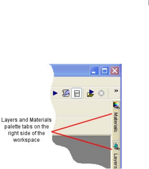
What was labeled the Layers palette in previous versions is now
called the Layers palette.
What was labeled the Material palette in version 8 is now called
the Materials palette. Additionally, the Materials palette now
contains the Frame tab, offering a new (and for some users a
more intuitive) method of choosing colors. Refer to Chapter 10
for more information.
Open images can optionally be displayed in a tabbed format
across the top of the workspace. To make an image active, click
the desired tab. When many images are open, use the forward and
backward buttons to scroll among the tabs. Refer to Chapter 2 for
more information.
The docking behavior of palettes has been modified. Palettes can
be set to slide open and closed from a tab along the right side,
roll up at a user-selected speed, or roll up into the nearest
quadrant of the workspace. Refer to Chapter 2 for more
information.

Chapter 1: Getting Started 3
The Customize dialog now contains a new tab called Scripts.
This tab lets you easily bind a script to one of 50 icons. The icon
can then be dragged onto a toolbar or into a menu. Refer to
Chapter 17 for more information.
The General Program Preferences dialog has new options for the
Crop tool's shading area, as well as the number of steps to save
for the History palette. Additionally the main workspace right-
click context menu now contains the command to access this
dialog in a single click. Refer to Chapter 4 for more information.
In the Adjust menu, the three Automatic correction commands
(Color Balance, Contrast Enhancement, and Saturation
Enhancement) have been pulled out of their former submenus
and now reside as standalone items. Additionally, the Adjust
menu contains a Photo Fix item loaded with helpful commands
geared toward quickly correcting common problems with digital
photos.
New Art Media Tools
Working in conjunction with the new Mixer palette, the new Art
Media tools let you create digital artwork that closely mimics
real-world media, pigments, paints, and artist's tools. The Oil
Brush creates realistic paint strokes, while the Chalk, Pastel,
Crayon, Colored Pencil, and Marker tools are used for making
dry-pigment works of art. Refer to Chapter 12 for more
information.

Chapter 1: Getting Started
4
Image Browser Updates
The Image Browser now contains two tabs, Find and Info, in the
left side of the Browser window. The Find tab contains the
familiar Windows Explorer-like navigation view, and the Info tab
displays image information, creator data, and EXIF data.
Additionally, with the Browser active you can choose File > Sort
and use the Sorting dialog to sort images by EXIF data. Refer to
Chapter 3 for more information.
Raw Camera Image Support
You can now open Raw (unprocessed) images from high-end
digital cameras in Paint Shop Pro. Additionally, a new File
Format Preferences tab contains an option for displaying a dialog
that allows for further Raw image editing before the image opens
in Paint Shop Pro. Refer to Chapter 4 for more information.
New Digital Photo Correction Filters
Four new filters provide innovative methods of correcting common
problems with digital photos:
The Digital Camera Noise Removal filter scans your photo and
removes image noise often inherent to digital cameras while
intelligently preserving normal image textures. You can even
customize noise removal by defining specific regions or color
ranges to focus on or ignore, and then save settings as a Preset
that can be applied to photos taken from the same camera.
The Chromatic Aberration Removal filter helps eliminate the
colored glow that often appears in digital photos, especially in an
image's high contrast images.
The Fill Flash filter corrects underexposed, shadowy areas of
your photos.
The Backlighting filter corrects the opposite problem by
compensating for overexposed areas surrounding the photo's
subject.
Refer to Chapter 5 for more information on these filters.
New Effects
Two new powerful and interesting effects include:

Chapter 1: Getting Started 5
The Displacement Map effect lets you create two or three-
dimensional surface effects using a different, underlying image
as the basis for the effect.
The Radial Blur effect lets you add interesting and fun spin,
twist, and zoom effects to an image.
Refer to Chapter 9 for more information on these effects.
Vector Drawing Tool Updates
Creating vector shapes has never been easier or more powerful.
The Pen tool's functionality has been simplified to offer a clearer,
more intuitive way to create and edit curves and lines.
Three new tools, Rectangle, Ellipse, and Symmetric Shape,
provide all the controls you need to create buttons, banners,
polygons, any kind of rectangle or ellipse or custom shape.
The Preset Shape tool provides you with a variety of arrows,
flowers, gears, and other miscellaneous shapes.
Refer to Chapter 13 for more information.
Text Tool Updates
The Text tool now provides a vertical text layout option, updates
to the text on a path feature, as well as new anti-aliasing
rendering options that generate cleaner text at smaller font sizes.
Refer to Chapter 16 for more information.
Crop Tool Updates
The Crop tool now provides the option of shading the area
outside the crop box. This option can be set in the Transparency
and Shading tab of the General Program Preferences dialog.
Refer to Chapter 7 for more information.
Print Layout Feature Updates
The Print Layout feature now lets you draw a text box on the
layout to easily add custom captions or titles to your printed
pages. Additionally, you can create elliptical cells and apply edits
to multiple cells simultaneously. Refer to Chapter 18 for more
information.

Chapter 1: Getting Started
6
System Requirements
Before installing Paint Shop Pro, make sure that your computer
meets the minimum system requirements, or matches/exceeds the
recommended configuration:
Minimum System Requirements
Windows® 98SE / 2000 (SP4)/ ME / XP
300 MHz processor or faster
256 MB RAM
500 MB free disk space
16-bit display adapter at 800 x 600 resolution
Microsoft Internet Explorer 6.0 or later
Recommended System Configuration
Windows XP
1.0 GHz processor or faster
512 MB RAM
500 MB free disk space
32-bit display adapter at 1024 x 768 resolution
Microsoft Internet Explorer 6.0 or later
Installing the Software
Before installing Paint Shop Pro, close any programs or applications
that you have running on your computer.
To install the software:
1 Insert the Paint Shop Pro CD in your CD-ROM drive. The
installation program starts automatically.
Note: If the installation program does not start automatically, use
Windows Explorer or double-click the My Computer icon,
navigate to the contents of the Paint Shop Pro CD, and double-
click the file Autorun.exe.
2 Follow the prompts to install the program.

Chapter 1: Getting Started 7
Learning Paint Shop Pro
Learn Paint Shop Pro in a variety of ways: in addition to reading this
User Guide, we encourage you to use the Help system, follow the
Quick Guides in the Learning Center palette, and visit our Web site
for even more learning resources.
Using the Quick Guides to Learn
Common Tasks
Quick Guides are short, fast tutorials that guide you through new
tasks and projects using your own image. Perform each step
yourself, or have the program show you where to find the tools
needed to complete the task.
To use Quick Guides:
1 Choose View > Palettes > Learning Center or press F10 to open the
Learning Center window.
2 Click the title of a Quick Guide to view the selected topic.
Using the Help System
When you start up the Paint Shop Pro Help system (by choosing
Help > Help Topics, or by pressing the F1 key) it will open to the
Welcome to Paint Shop Pro page. The left side of the Help window
contains the Contents tab (listing all the main Help pages), the Index
tab, the Search tab, and the Favorites tab. The right side of the Help
window displays the currently selected Help topic.
Most command dialogs have a Help button located along the bottom
of the dialog. Click that button to open a Help topic associated with
the dialog.
Context-Sensitive Help Tool
To display Help about a particular user interface item, such as a tool
or button or menu item, use the Context Help button as follows:
1 Choose Help > Context Help. The cursor shape changes to:
2 Drag the cursor over the item you want to display Help for, and
then click the mouse. The Help file will open and display the
Help topic associated with what you clicked.

Chapter 1: Getting Started
8
Using the Jasc Software Learning
Center
The Jasc Software Learning Center shows you how to use Paint
Shop Pro’s features to create amazing photograph enhancements and
sophisticated graphics. Jasc and third-party tutorials walk you
through the steps for everything from restoring old photographs to
creating metallic text.
To access the Jasc Software Learning Center, use your internet
browser to got to www.Jasc.com, and then click the Support link.
In addition to Learning Center tutorials, you'll also find Knowledge
Base articles and other helpful materials.
Using Web-Based Resources
On the Help menu of Paint Shop Pro, you can access a number of
Web site pages dedicated to support issues. In the Help menu select
one of the following Web site links:
Online Support and Resources Access the Jasc Customer Care
Center to search for answers in our Knowledge Base, submit
questions to Technical Support, or give us feedback.
Register Product Online Register your copy of Paint Shop Pro
online.
Check for Updates Check the Jasc.com Web site for updates to
Paint Shop Pro.
Contact Information Send an e-mail message to Technical
Support.
Getting in Touch with Other Paint Shop Pro Users
Millions of people use and love Paint Shop Pro. There are many
independent (non-Jasc) Paint Shop Pro communities where users
share tips and tricks, ask questions, and get answers about Paint
Shop Pro. There are Web sites, newsgroups, and chatrooms devoted
to Paint Shop Pro. As a starting point, search online for “Paint Shop
Pro.”
Popular newsgroups include forums.jasc.com as well as the Usenet
newsgroup, comp.graphics.apps.paint-shop-pro. You can access
newsgroups using your favorite news reader such as Microsoft
Outlook Express, or an on-line news reader such as Google Groups.

9
Getting to Know The Program
The Paint Shop Pro workspace includes menus, tools, toolbars, and
palettes that you use to create and edit images. Becoming familiar
with this workspace will help you accomplish your photo editing,
painting, and drawing tasks.
Contents Starting and Exiting Paint Shop Pro . . . . . . . . . . . . . . . . . . . . . . 10
Exploring the User Interface. . . . . . . . . . . . . . . . . . . . . . . . . . . . 10
Using Shortcut and Function Keys . . . . . . . . . . . . . . . . . . . . . . . 11
Using Toolbars and Palettes . . . . . . . . . . . . . . . . . . . . . . . . . . . 12
Working with Dialogs . . . . . . . . . . . . . . . . . . . . . . . . . . . . . . . . . 19
Viewing Images. . . . . . . . . . . . . . . . . . . . . . . . . . . . . . . . . . . . . 22
Viewing Image Information. . . . . . . . . . . . . . . . . . . . . . . . . . . . . 28
CHAPTER 2

Chapter 2: Getting to Know The Program
10
Starting and Exiting Paint Shop Pro
To start Paint Shop Pro:
If you chose to place the Paint Shop Pro icon on your desktop
during installation, you can start the program by double-clicking
this icon.
If you chose not to place the Paint Shop Pro icon on your
desktop, start the program by clicking the Start button and
choosing All Programs > Jasc Software > Jasc Paint shop Pro 9.
The first time you start Paint Shop Pro, the program displays the File
Format Associations dialog. This dialog lets you assign file formats
to the program so that your computer always uses Paint Shop Pro to
open files in those formats. You can change associations at any time
by choosing the File > Preferences > File Format Associations menu
commands. For more information, see “Setting File Format
Associations” on page 79.
To exit paint Shop Pro:
Exit Paint Shop Pro using one of the following methods:
Choose File > Exit; or
Click the Close button in the upper right-hand corner of the
main window's title bar; or
Click the Paint Shop Pro icon in the upper left-hand corner
of the main window title bar and choose Close from its menu.
Note: Note: If there are unsaved images open in the
workspace, you'll be prompted to save them before closing the
program.
Exploring the User Interface
When you open Paint Shop Pro, it displays the main program
window. This window is your work area. It contains the commands
and tools used to create, edit, print, and export your images.
The Paint Shop Pro workspace includes the following components:
Menu bar The menu bar displays commands for performing tasks.
Menus are organized by topic. For example, the Effects menu
contains commands for applying effects to images.

Chapter 2: Getting to Know The Program 11
Toolbars The toolbars display buttons for common commands. See
“Using Toolbars” on page 14.
Palettes The palettes display information and help you select tools,
modify options, manage layers, select colors, and perform other
editing tasks. See “Using Palettes” on page 15.
Status bar The Status bar displays text about the selected tool or
menu command as well as image information, including the
dimensions and color depth. See “Viewing Image Information” on
page 28.
Browser Displays thumbnail previews of image files. You can open,
delete, copy, and perform other file commands in the Browser. For
more information, see “Using the Paint Shop Pro Browser” on
page 44.
Print Layout window Displays a window on which you can arrange
and size multiple images, add text captions, apply templates, and
then print the images. For more information, see “Printing a Single
Image” on page 446.
Using Shortcut and Function Keys
To work quickly and easily in Paint Shop Pro, learn the shortcut and
function keys for common tasks. Key combinations like Ctrl + Z
(Undo) and Ctrl + C (Copy) become second nature as you work, and
they save time over using the mouse.
Here are the ways you can use shortcut and function keys in Paint
Shop Pro:
Use shortcut keys to execute menu commands, display palettes,
edit nodes on vector objects, and execute Browser commands.
All menu commands list their shortcut keys on the menu.
Shortcut keys for palettes are listed on the View > Palettes menu.
Use shortcut keys to select tools. Move the cursor over a tool to
display a ToolTip with its shortcut key in parentheses.
Use function keys to display a menu by pressing Alt plus the
underlined letter of the menu name (for example, press Alt + F for
the File menu). Then, press the underlined letter of a menu
command or scroll through menus using the arrow keys. Press
ESC to return to your image without executing a command.
To display all default shortcut keys, choose Help > Keyboard Map.
Customizing Shortcut Keys
If you don’t like the assigned
function keys, you can customize
the function keys to suit your
needs. See “Assigning and
Viewing Shortcut Keys” on
page 81.
To view all assigned keys,
including custom shortcuts, choose
Help > Keyboard Map.

Chapter 2: Getting to Know The Program
12
Using Toolbars and Palettes
One aspect of customizing your workspace involves the ability to
dock, float, resize, and move the toolbars and palettes. The sections
below describe how to work with palettes and toolbars.
To allow for palette docking:
1 Choose View > Docking Options. The Palettes tab of the
Preferences dialog appears.
2 In the Allow docking of section, mark the palettes you want to be
able to dock.
Note: Even if a palette is set for docking, by holding down Ctrl and
then dragging the palette you can place it anywhere in the
workspace.
Pushpin Button in a Toolbar or Palette Title Bar
Be aware of the pushpin button in the toolbar/palette's title bar as
it relates to floating and docking:
When the toolbar/palette is floating:
When the pushpin is pointing down, the toolbar/palette will
remain fully displayed when you move the cursor away from it.
When the pushpin is pointing to the left , the toolbar/palette
will roll up so that only its title bar is visible.
When the palette is docked:
(For palettes only) When the pushpin button is pointing down,
the palette will remain fully displayed in its docked position
when you move the cursor away from it.
Chapter 2: Getting to Know The Program 13
(For palettes only) When the pushpin is pointing to the left, the
palette will slide into the workspace side. You'll then see a tab
with the palette name. To display the palette again, move the
cursor over the tab.
The Animate Auto Hide and Quadrant Rollup
Options
The way in which floating palettes roll up can be modified by two
settings in the Options tab of the Customize dialog. (Choose View >
Customize to display this dialog.)
To set the speed in which floating palettes roll up, mark the
Animate Auto Hide check box, and then drag the Speed slider to
the desired setting.
To have the title bar of rolled up floating palettes move into the
nearest workspace quadrant, mark the Quadrant Rollup check
box. (The Quadrant Rollup check box is marked by default.)
When this box is not marked, floating palettes will roll up and
their title bar will not move.
To dock a toolbar or palette:
Double-click its title bar; or
Drag its title bar to one edge of the workspace. The toolbar or
palette snaps into place.
To float a toolbar:
Double-click its handle; or

Chapter 2: Getting to Know The Program
14
Place the cursor over the handle (you'll get the four-sided mover
icon) and drag the handle to move the toolbar away from the
workspace edge. Note: The handle size and position will vary
depending on the toolbar's size and whether it is vertical or
horizontal.
To move an undocked toolbar or palette:
Drag its title bar to a new position.
To resize a toolbar or palette:
Click and drag the sides or corners of a toolbar or palette to change
its size.
To display all toolbars and palettes:
Press Ctrl + Shift + T.
Note: To hide a specific palette, click the Close button on its title
bar.
Using Toolbars
The toolbars display buttons for the most common tasks. Position the
cursor over a button to display a ToolTip with its name. The Status
bar displays more information about the command.
Display or hide toolbars, or arrange them on the workspace. Dock a
toolbar to snap it into place at an edge of a workspace, or to float it
to move it anywhere on the screen.
Paint Shop Pro contains these toolbars:
Standard toolbar Displays the most common commands, such as
saving images, undoing a command, and cutting items. Paint Shop
Pro automatically displays this toolbar when you first run the
program.
Tools toolbar Crop, paint, draw, type, and perform other image
editing tasks. See “Using the Tools” on page 17.
Browser toolbar Displays commands for using the Paint Shop Pro
Browser.
Effects toolbar Displays commands for applying effects to your
images.
Status bar
The Status bar displays text about
the selected tool or menu
command, as well as image
information including the
dimensions, color depth, and
cursor position. For more
information, see “Viewing Image
Information” on page 28.

Chapter 2: Getting to Know The Program 15
Photo toolbar Displays commands for enhancing photos.
Script toolbar Displays commands for creating and running scripts.
Web toolbar Displays commands for creating and saving images for
the Web.
To execute a toolbar command:
Click the command button. If the button is greyed out, it is not
available.
To display or hide a toolbar:
Do either of the following:
Choose View > Toolbars and choose the toolbar from the menu.
Right-click any toolbar or palette, choose Toolbars, and then
choose the toolbar from the context menu.
Note: To hide a specific toolbar or the palette, click the close
button on its title bar.
Using Palettes
Use palettes to choose tools and tool options, select colors, and
manage layers. Display or hide palettes, or arrange them on the
workspace. Dock a palette to snap it into place at an edge of a
workspace, or to float it to move it anywhere on the screen.
Paint Shop Pro contains these palettes:
Materials palette Select colors and materials for painting, drawing,
filling, and retouching. Refer to Chapter 10 for more information.
Tool Options palette Modify options for the currently selected tool.
See “Setting Tool Options” on page 17.
Layers palette View, organize, and edit image layers. See “About
Layers” on page 360.
History palette Lists the actions taken on the current image, allows
you to undo and redo adjacent or non-adjacent actions, and allows
you to create Quickscripts. Refer to Chapter 7 for more information.
Mixer palette Place and mix pigments for use with the Art Media
tools, allowing you to create realistic oil paint strokes, as well as
chalk, colored pencil, and marker strokes. Refer to Chapter 7 for
more information.
Learning Center palette Displays tutorials for common tasks. See
“Using the Quick Guides to Learn Common Tasks” on page 7.
Customizing toolbars
You can add and remove buttons
from toolbars and create your own
toolbars. For more information, see
“Customizing Toolbars and Menus”
on page 56.
Flyout menu displaying toolbars
Chapter 2: Getting to Know The Program
16
Histogram palette Displays a graph of the distribution of red, green,
blue, greyscale, hue, saturation, and lightness values in an image.
Analyze the distribution of detail in the shadows, midtones, and
highlights to decide how to make corrections. See “Using the
Histogram to Analyze Images” on page 145.
Overview palette Displays a thumbnail view of the active image, as
well as information about the image. See “Using the Overview
Palette” on page 18.
Script Output palette Displays actions you take and the results of
running scripts. See “About the Script Output Palette” on page 427.
Brush Variance palette Sets additional brush options. This palette is
particularly useful if you have a 4D mouse or a pressure-sensitive
tablet. For example, you can vary the opacity of a brush stroke by
applying pressure with the stylus. You can use some options with a
mouse.
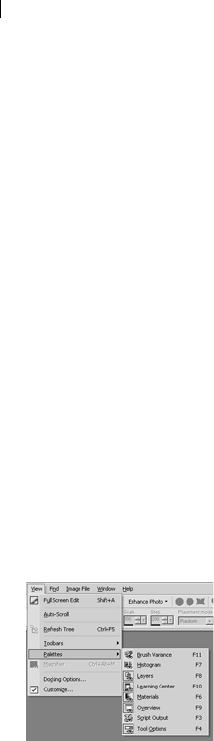
To display or hide a palette:
Do one of the following:
Choose View > Palette and choose the palette name.
Type the palette’s shortcut key (listed to the right of the name).
Right-click any palette and choose the palette name from the
context menu.
To set the docking preference of palettes:
Choose File > Preferences > General Program Preferences and click
the Palettes tab of the dialog. In the Allow docking of group box,
mark the check boxes of the palettes you want Paint Shop Pro to
dock automatically when you drag them to the edge of the
workspace.
Note
You can also open the Palettes tab of the Paint shop Pro 9
Preferences dialog by choosing View > Docking Options.
To resize a palette:
Click and drag a corner or an edge, or use the Minimize and Maximize
buttons in the upper right corner.
Flyout menu displaying pallets
Chapter 2: Getting to Know The Program 17
Using the Tools
Use the Paint Shop Pro tools to perform actions such as crop, paint,
draw, add text, and perform other image editing and creative tasks.
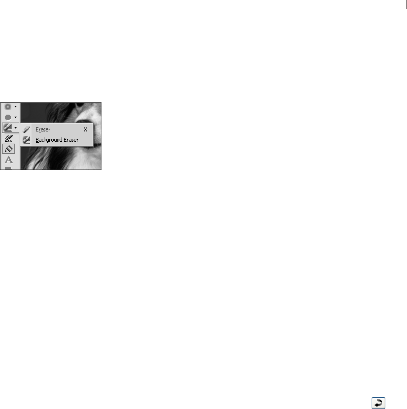
Select a tool by clicking its button on the Tools toolbar. Some tools
(for example Crop, Move, and Text) reside in their own space on the
Tools toolbar. Most other tools, however, are grouped with other
tools that perform similar tasks. A group of tools is denoted by a
small arrow on the right side; click the arrow to reveal the other
tools.
To view information about a tool, hold the cursor over it. A tool tip
displays the tool name and shortcut key, and the Status bar (located
along the bottom of the main Paint Shop Pro window) displays hints
for using the tool.
To use a tool:
1 Click its button on the Tools toolbar. For tools that share a flyout
with other tools, click the down-arrow next to the tool and select
the tool.
2 Specify options using the Tool Options palette. See “Setting Tool
Options” below.
3 Use the tool on the image.
For information on moving, hiding, and displaying the Tools toolbar,
see “Using Toolbars” on page 14.
Resetting Tool Options to Default Values
To reset the Tool Options palette to the default values, click the
Presets drop-list and then click the Reset to default button .
Setting Tool Options
After you select a tool from the Tools toolbar, set its options in the
Tool Options palette. Options include such settings as brush size and
shape for painting tools and line width for drawing tools. By default,
the palette is below the Standard toolbar. The palette displays
options grouped into bands, which you can minimize and drag
within the palette. To display a minimized band, click its handle or
right-facing arrow.
Set the options before you use the tool. You cannot edit settings in
the Tool Options palette for brush strokes or objects you have
already created.
Flyout menu displaying tools
Why some tools are inactive
(greyed out)
Some tools work only on raster or
vector layers. For example, the
Paint Brush and Clone Brush work
only on raster layers; the Object
Selection tool works only on vector
layers.
For information on raster and
vector layers, see “About Layers”
on page 360.

Chapter 2: Getting to Know The Program
18
Although the items in the Tool Options palette depend upon the
active tool, here are features common to all or some of the tools:
Presets Scripts that load specific settings for a tool. For more
information, refer to Chapter 17.
Arrow button When more tool options are available than there
is room to show them, click these buttons to reveal the additional
options.
Apply button Some tools (Crop, for example) have this
button. Click it to apply the changes you have made or execute
the action.
Here is an example of an un-docked Tool Options palette for the Oil
Brush tool:
Using the Overview Palette
Display the Overview palette to preview the entire active image or to
view image information. The Overview palette displays a rectangle
over the part of the image visible in the image window. To show
other areas of the image, click and drag this rectangle.
The Overview palette contains two tabs:
Preview Displays the image preview. The image updates after you
complete an action. Transparent areas of the image appear as white.
Info Displays image status information including height and width,
color depth, memory used, cursor position, rotation, and other
information.
The Overview palette
Chapter 2: Getting to Know The Program 19
Using Context Menus
Context menus provide quick access to commands specific to the
active tool, selection, or palette.
Note
For a complete list of Context menus, choose View > Customize to
open the Customize dialog. Click the Menu tab, and select a context
menu from the Select context menu drop-down list.
To use a context menu:
1 Position the cursor over an image, an empty area of a palette, a
layer name on the Layers palette, a thumbnail in the Browser, or a
toolbar.
2 Right-click to display the context menu.
3 Choose a command from the menu.
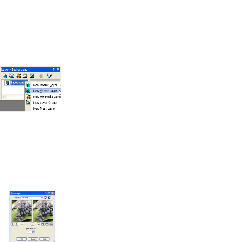
Working with Dialogs
Dialogs are windows that open when you choose certain Paint Shop
Pro commands. Use them to select and preview command options.
All dialogs remember where you last positioned them on the screen
and re-open in the same location.
Most dialogs have the following features in common:
Preview windows Zoom and navigate to see before and after views
of changes.
Presets Saved settings, or scripts, that you can use to make quick
changes to images. Use the presets that come with Paint Shop Pro or
create your own. For more information on creating and using
presets, refer to chapter 17.
Numeric edit controls The controls that you use to select a value.
Color boxes The box you click to select a color.
Randomize parameters button A button you click to try out random
settings in the dialog.
Resize Handle A handle in the lower right corner of the dialog used
to change the size of the dialog.
Context menu for the
Layers palette
The Average dialog
Chapter 2: Getting to Know The Program
20
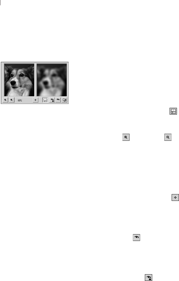
Using Preview Windows
Most dialogs that correct images, apply effects, or modify selections
have two preview windows that show the image before and after
changes are applied. Use the window controls to zoom the preview
in or out, pan it, or proof changes on the actual image.
You can show or hide the preview windows. When you hide
previews, use the main image window to proof changes.
To display or hide preview windows:
Click the Show/Hide Previews button .
To zoom the image preview:
Click the Zoom In or Zoom Out buttons. The zoom
percentage displays next to the Zoom buttons.
To pan the image:
Do either of the following:
Move the cursor over either preview window (the cursor changes
to a hand), and then click and drag the image.
Click and hold the Navigate button , and then center the
selection rectangle over the part of the image you want to
display.
To proof changes in the main image window:
Click the Proof button . All settings in the dialog are applied to
the main image window. Each time you change settings, click the
Proof button to view the changes in the main image window.
To set automatic proofing:
Click the Autoproof button .
Paint Shop Pro automatically applies all dialog settings to the main
image window each time you change a setting.
The preview windows
Size the dialog
In each Paint Shop Pro dialog with
preview windows, you can size the
dialog by clicking and dragging a
corner. Expand a dialog when you
want the preview windows to be
large enough to see detailed
changes. You can also double-
click the dialog title bar to
maximize the dialog.
Exceptions to panning in
the left preview window
In a few dialogs, the left preview
window is used for making
selections (such as selecting a red
eye in the Red Eye Removal
dialog). In these dialogs, the
cursor does not change to a hand
over the left preview window. Use
the right preview window for
panning instead.
Chapter 2: Getting to Know The Program 21
Using Preset Settings
Presets are saved settings, or scripts, that you can use to make quick
changes to images. Use the presets that come with Paint Shop Pro or
create your own. For more information on creating and using
presets, refer to Chapter 17.
Editing Numerical Values
To edit numbers in Paint Shop Pro dialogs, you use the Jasc numeric
edit controls, which provide an easy way to edit numbers and change
settings.
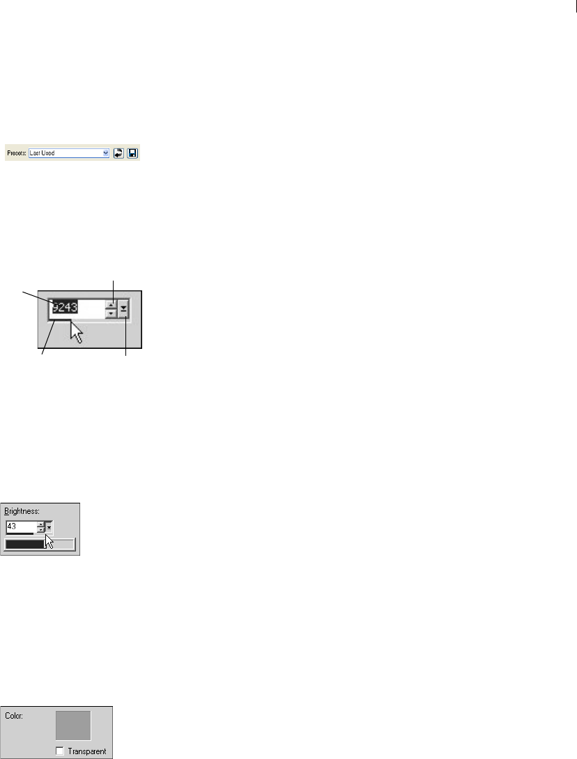
To edit numbers:
Do one of the following:
To enter a specific value, click the edit box, use the Delete or
Backspace key to delete the number as needed, and then type a
new value. You can also double-click the number to highlight it,
and then type a new value.
Note: If you type a value in the edit box that is out of range for
the control, the box turns red.
To increase or decrease the number by one, click the up or down
arrow of the spin controls.
To choose an approximate value, click once at a position on the
meter bar.
To choose from the range of possible settings, click and hold the
mouse button down on the meter bar or the slider button, drag to
select a desired setting, and release the mouse.
Using Color Boxes
In some dialogs, a color box displays the currently selected color.
When you move the cursor over the color box, the cursor changes to
a dropper and displays the RGB values. Click the color box to select
another color:
Left-click the color box to select from the Color dialog.
Right-click the color box to select from recently used colors.
Presets in a dialog
Numeric edit controls
Slider button
Spin controls
Edit
box
Meter bar
Using sliders to select values
The color box in the New Image
dialog.
Chapter 2: Getting to Know The Program
22
Randomizing Parameters
Many correction and effect dialogs have a Randomize parameters
button. Click this button to update all dialog settings with random
values. To try out a variety of settings, click the button multiple
times.
To randomize settings within a dialog:
Click the Randomize parameters button .
Resizing a Dialog
All dialogs contain a Resize Handle in the lower right corner of
the dialog. Click and drag the handle to resize the dialog.
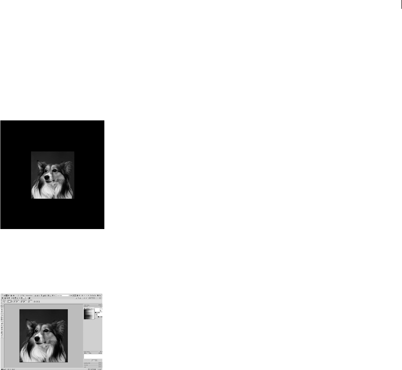
Viewing Images
The image window displays your image. You can move or size the
image window or open the same image in multiple image windows
(for example, to see the image at different magnifications).
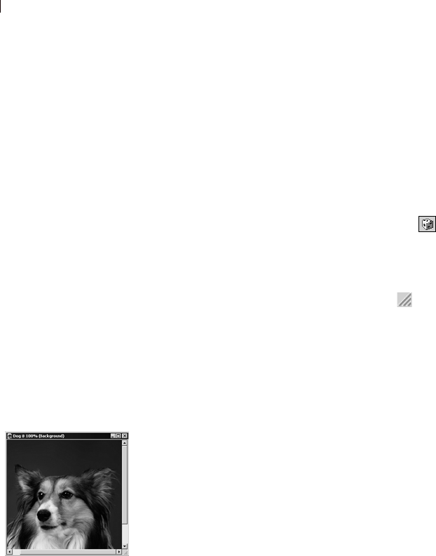
The title bar at the top of the image window shows the file name and
the magnification percentage. An asterisk after the filename
indicates the image has been modified since you last saved it.
To see a thumbnail of the entire image, display the Overview palette.
To move an image window:
Click and drag the title bar to move an image to a new position in the
workspace.
To resize an image window:
Click an edge or a corner of the image window and drag it to a new
position.
If the image is larger than the window, use the scrollbars to view
another area of the image.
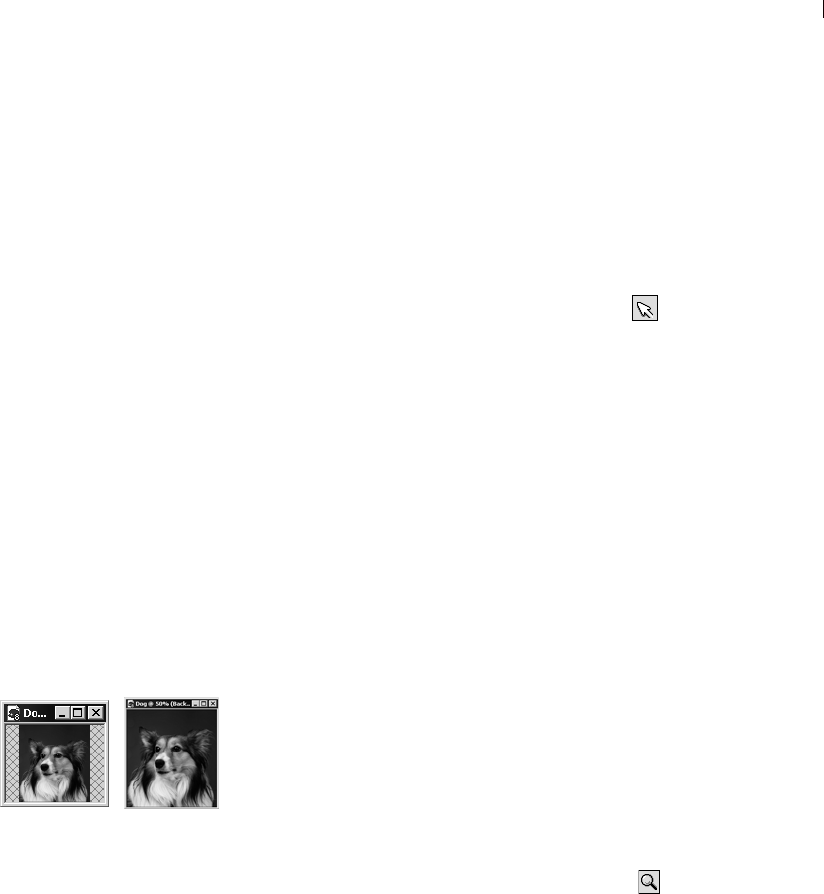
To minimize or maximize an image window:
To minimize an image window so that only its title bar appears, click
the Minimize button located in the upper right corner of the image's
title bar. Click the Restore button to display the image window at its
previous size.
An image window
Does the image have a
watermark?
If the image has an embedded
watermark, a copyright symbol is
displayed in front of its name. For
more information on watermarks,
see “Using Digital Watermarks” on
page 480.

Chapter 2: Getting to Know The Program 23
To maximize an image window that it fills the Paint Shop Pro
workspace, click the Maximize button located in the upper right
corner of the image's title bar.
To close an image window:
Click the Close button located in the upper right corner of the
image's title bar. If you have unsaved changes to the image, you'll be
prompted to save the changes.
To open multiple views of the same image:
Choose Window > New Window or press Shift + W.
A new window opens with another view of the active image. When
you make changes in one window, the other is updated.
To make a copy of the active image:
Choose Window > Duplicate or press Shift + D.
A copy of the active image opens and can be edited independent
from the original image.
To arrange multiple windows:
Do either of the following:
Choose Window > Cascade to display windows stacked and
cascading from the upper left to the lower right of the workspace.
Choose Window > Tile Vertically or Window > Tile Horizontally to
display windows side by side vertically or horizontally. Windows
are resized to fit within the workspace.
To close an image window:
Do either of the following:
To close an active window, choose File > Close or click the Close
button on the title bar of the image.
To close all windows, choose Window > Close All.
If there are any unsaved changes in the images, you will be
prompted to save the files.
Save time by saving
workspaces
Did you know that you can save
entire workspaces, not just
images? The workspace includes
open images, their magnifications
and screen positions, as well as
the positions of palettes, toolbars,
and windows.
For more information, see “Using
Custom Workspaces” on page 54.
Chapter 2: Getting to Know The Program
24
To see a list of all open images:
At the bottom of the Window menu the file names for all open
images appear. The file names are listed in the order they were
opened in Paint Shop Pro.
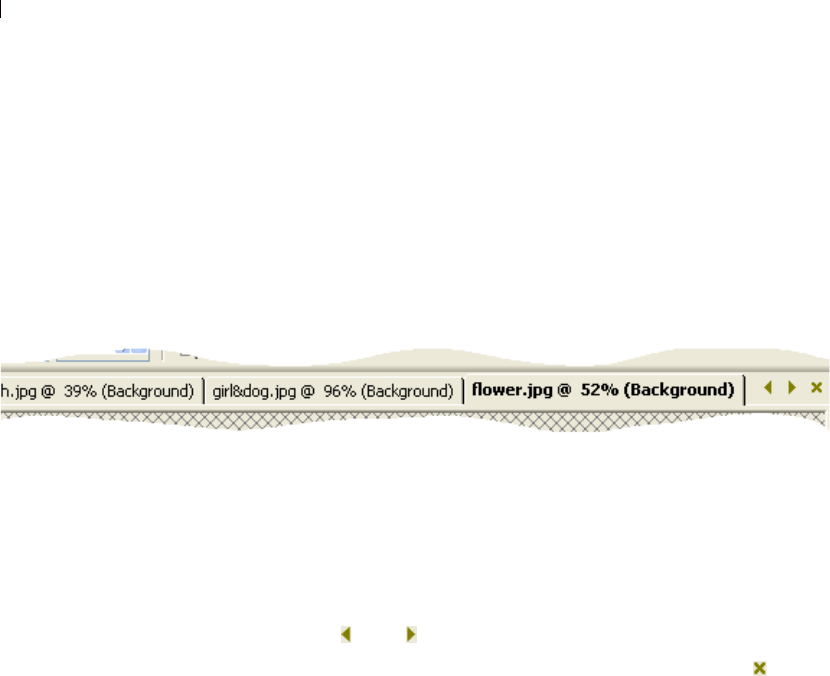
Tabbed Image Windows
Paint Shop Pro 9 gives you the option of displaying open images in a
tabbed format.
To set this option, choose Window > Tabbed Documents. To turn off
this feature and go back to the floating image windows, choose this
option again.
When this option is on, the active image covers the entire
workspace, and its bolded file name appears in a tab across the top of
the workspace. Each open image has a separate tab. To view another
image, click its tab. To access an image tab not in the current view,
click the and buttons.
To close an image in tabbed format, click the Close button .
Note: When the Tabbed Document option is on, the concept of
minimizing and maximizing the image window no longer applies.
Chapter 2: Getting to Know The Program 25
Navigating the View Area
When an image is too large to fit within its window, scroll bars
appear on the bottom and right sides of the image.
To view another area of the image:
Do one of the following:
On the Tools toolbar, choose the Pan tool , and then click and
drag in the image.
Click and drag the horizontal or vertical scroll bar.
Press the arrow keys to move the image by small increments.
Display the Overview palette (choose View > Palettes >
Overview), and then drag the preview rectangle to a new position.
To fit the window to the image:
Choose Window > Fit to Image or press Ctrl + W.
Magnifying and Reducing the View
Magnify the view of an image (zoom in) to view and edit image
details or reduce the view (zoom out) to see the overall image. The
title bar of the image window displays the zoom percentage.
To zoom in:
Do one of the following:
Zoom with the mouse wheel, roll the optional wheel on your
mouse to zoom in or out quickly.
On the Tools toolbar choose the Zoom tool (if necessary, click
the down-arrow next to the Pan tool), and then left-click the area
you want to magnify. The view magnifies to the next preset
percentage with each click, up to the maximum magnification of
5000%.
Choose the Zoom tool or the Pan tool, and then in the Tool
Options palette select a zoom percentage or click the Zoom In or
Zoom In More buttons.
Choose View > Zoom > Zoom In to magnify the view to the next
preset percentage.
Choose View > Zoom > Zoom In More to magnify the view by five
preset percentages.
Zooming in and out
Automatic resizing
By default, when you zoom in or
out the image window is
automatically resized to fit the
image. To change this preference
setting, see “View Preferences” on
page 60.

Chapter 2: Getting to Know The Program
26
To zoom out:
Do one of the following:
On the Tools toolbar, select the Zoom tool (if necessary, click
the down-arrow next to the Pan tool) and then right-click the area
you want to reduce. The view reduces to the previous preset
percentage with each click, down to a minimum magnification of
1%.
Choose the Zoom tool or the Pan tool, and then in the Tool
Options palette select a zoom percentage or click the Zoom Out
or Zoom Out More buttons.
Choose View > Zoom > Zoom Out to reduce the view to the next
preset percentage.
Choose View > Zoom > Zoom Out More to reduce the view by five
preset percentages.
To magnify a specific area:
1 Choose View > Magnifier. This puts the cursor in magnifier mode.
2 Place the cursor over the part of the image you want to magnify.
The selected area is displayed at the highest percentage that will
fit within the window.
3 To turn off magnifier mode, choose View > Magnifier again.
Chapter 2: Getting to Know The Program 27
Previewing and Editing Using the
Full Screen
Use the Full Screen Preview command to preview an image without
any of the menus, toolbars, or palettes visible.
Use the Full Screen Edit command to expand the entire workspace,
giving you the largest possible space for displaying and editing
images. The palettes and toolbars are visible but the menus, Paint
Shop Pro title bar, and Status bar are hidden.
To preview an image on the full screen:
1 Choose View > Full Screen Preview or press Ctrl + Shift +A. The
workspace disappears and the image displays at its current
magnification.
2 To return to the Paint Shop Pro workspace, press any key.
To edit using the full screen:
1 Choose View > Full Screen Edit or press Shift + A. The menu bar
and status bar disappear.
To select from a menu when using the full screen, move the
cursor to the top of the screen and left-click. The menus appear
as you move the mouse along the top.
2 To return the window to its previous size, press Shift + A.
Previewing on the full screen
Editing using the full screen
Chapter 2: Getting to Know The Program
28
Viewing Image Information
As you work with an image, you may want to view information
about it. There are several ways to do this, as described in the
sections below.
To view general image information:
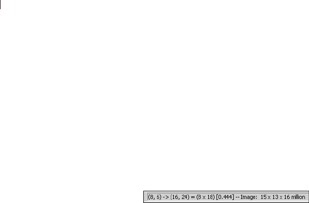
Look at the Status bar (along the bottom of the main Paint Shop
Pro window) to see the cursor position, image height and width
in pixels, and the color depth.
Display the Info tab of the Overview palette to view information
about the image. Choose View > Palettes > Overview, and then
click the Info tab. The information displayed depends on what
tool is selected.
To view image color information:
Choose Image > Count Image Colors to display the number of unique
colors in the image.
To view detailed image information:
1 Choose Image > Image Information, or press Shift + I.
2 Do one of the following:
Click the Image Information tab to view the file name and
format, image dimensions, resolution, and color depth,
modification status, number of layers and alpha channels, and
the amount of RAM and disk space used for the image as well
as its selections, masks, alpha channels, and undo storage.
Click the Creator Information tab to view or edit the image
title, artist name, copyright, description, date created, and date
modified.
Click the Watermark Information tab to view and enter
information on Digimarc watermarking.
Click the EXIF Information tab to view information for images
taken with digital cameras. In the Section group box, mark the
check boxes for the information you want to display: Input
Device, Artist, Date, Image, Shot Conditions, and GPS.

29
Getting Images into Paint Shop Pro
You can get images into Paint Shop Pro in a variety of ways: import
images (from a digital camera, card reader, or scanner), capture
images from the computer screen, duplicate an existing image or
layer, or create a new image.
Contents Importing Images from Digital Cameras and Scanners. . . . . . . . . 30
Opening Existing Images . . . . . . . . . . . . . . . . . . . . . . . . . . . . . . 33
Creating Images . . . . . . . . . . . . . . . . . . . . . . . . . . . . . . . . . . . . 35
Capturing Images from the Computer Screen . . . . . . . . . . . . . . . 41
Opening Frames from Animation Shop . . . . . . . . . . . . . . . . . . . . 43
Using the Paint Shop Pro Browser . . . . . . . . . . . . . . . . . . . . . . . 44
Saving Image Files . . . . . . . . . . . . . . . . . . . . . . . . . . . . . . . . . . 49
Closing Image Files. . . . . . . . . . . . . . . . . . . . . . . . . . . . . . . . . . 52
CHAPTER 3

Chapter 3: Getting Images into Paint Shop Pro
30
Importing Images from Digital Cameras and
Scanners
With Paint Shop Pro you can access and manage your images while
they are in your digital camera. You can also load the images directly
into Paint Shop Pro.
Before you can view and download images from a digital camera,
card reader, or scanner you must install the special software (called
drivers) that enables your computer to connect to the camera, card
reader, or scanner. You must install this software before connecting
the camera, card reader, or scanner to the computer. Refer to the
documentation supplied with your camera, card reader, or scanner
for more information about this software.
Determine which type of connection your camera, card reader, or
scanner uses:
WIA The default for WIA compatible computers running the
Windows XP and ME operating systems. Your camera, card
reader, or scanner must support WIA.
Mounted Drive The default for non-WIA computers, and the most
common type of connection. Some cameras and scanners, and
most card readers are viewed as an additional disk drive when
they are connected to the USB port of your computer.
TWAIN Most cameras and scanners are TWAIN-compliant. Use
this setting if your camera, scanner, or card reader is TWAIN-
compliant.
Running scanning software
In addition to running the scanning
software from Paint Shop Pro, you
can also run the software from the
Windows Start menu. After you
perform the scan, you then need to
run Paint Shop Pro.

Chapter 3: Getting Images into Paint Shop Pro 31
Downloading Images Using
Windows XP, ME and a USB Cable
Paint Shop Pro supports the WIA connection protocol. If your
computer has the Windows XP or ME operating system, your camera
or scanner uses the WIA connection system, and you connect your
camera or scanner to the computer using a USB cable, then Paint
Shop Pro and Windows XP or ME will automatically detect when
you have connected your camera to your computer.
To download from a WIA camera or scanner with Windows XP or
ME:
1 Connect the camera, card reader, or scanner to the computer using
the USB cable.
2 Choose File > Import > From Scanner or Camera to download the
images to your computer.
Downloading Images From a Mounted
Drive
Some cameras, card readers, and scanners display as a separate drive
(assigned a drive letter) on your computer. For example, your
camera may display as My Computer\Removable Disk (G:).
To download from a camera, card reader, or scanner that appears
as a mounted drive:
1 Choose File > Open to open the Open dialog. Or choose File >
Browse and use the browser to locate the images on the mounted
drive.
2 Navigate to the drive for your camera, card reader, or scanner.
3 Locate the images that you want to download in a folder or sub-
folder of that drive.
4 Select the images that you want to download and click Open to
open the images in Paint Shop Pro.
Viewing EXIF Data
EXIF stands for Exchangeable
Image File Format. If your camera
supports this standard, it will record
the time & date the image was
taken, exposure information (ISO,
shutter, aperture) and other camera
details in the header of each image
file. To view EXIF data, choose
Image > Image Information to
open the Current Image
Information dialog, and then click
the EXIF Information tab.

Chapter 3: Getting Images into Paint Shop Pro
32
Importing Images Using the TWAIN
Interface
To import images using the TWAIN interface:
1 Choose File > Import > TWAIN > Select Source. The Select Source
dialog lists the TWAIN-compliant devices connected to your
computer.
Note: You only need to select the source the first time you
connect to the camera, card reader, or scanner.
2 Click the name of the device, then click Select.
3 Choose File > Import > TWAIN > Acquire to run the device’s
software.
4 Do one of the following:
For scanners, perform the scan using the device’s software.
(Refer to the scanner manufacturer’s documentation for
details.)
For digital cameras, an Import dialog displays. Select the
images that you want to download, and then click Download.
When the device and software finish processing the image, the
image is sent to Paint Shop Pro and placed in an image window.
The software remains open so you can continue to acquire
images or close the software.
5 Click the Paint Shop Pro icon in the Windows task bar to display
Paint Shop Pro and your image.
6 Choose File > Save As to save the image.
What does your image
need?
Here are some edits your digital
photograph may need:
Crop the image. Cropping
reduces the amount of memory
the image uses and eliminates
extra areas of color, which may
allow you to make better color
corrections.
Correct colors or retouch parts of
the image.

Chapter 3: Getting Images into Paint Shop Pro 33
Opening Existing Images
You can open images in a variety of file formats. The list of formats
you can open in Paint Shop Pro appears in the Open dialog.
You can select which formats Paint Shop Pro displays as available to
open.
You can open a file using the Open dialog or the Browser or by
choosing a recently used file from the File > Recent Files menu.
With the Open dialog, you can view a preview of each image file
that you select. With the Browser, you can view previews of all
image files within a folder. When you open a file via the Browser,
the Browser window stays open until you close it.
To open an image file using the Open dialog:
1 Do one of the following:
Choose File > Open.
Click the Open button .
Press Ctrl + O.
2 In the Look in drop-down list, select the folder where the file is
stored.
3 Click the name of the file you want to open. To select multiple
files, press Ctrl and click each name.
4 To view information or a preview of the image, choose an option:
Details Click this button to open a pop-up that displays
information about the selected image. Click OK to close this pop-
up.
Show preview Mark this check box to display the selected image
in the preview area. If you have selected multiple files, no
preview is displayed; use the Browse window instead.
5 Click Open.
To open an image file using the Browser:
1 Do one of the following:
Choose File > Browse; or
Click the Browse button ; or
Press Ctrl + B.
From open to browse
While opening a file from the Open
dialog, you may decide you want to
preview all files in a folder. Click
the Browse button to open the
Browser.

Chapter 3: Getting Images into Paint Shop Pro
34
The Browse window opens. Note that the Paint Shop Pro menu
bar displays commands specific to when the Browse window is
active. The Browse menu is active until you open a new file or
click an open image.
2 In the left side of the Browse window you’ll see the Find and
Info tabs. Use the Find tab like you would Windows Explorer to
navigate and then select the folder that contains the file you want
to open. Use the Info tab to display image information on a
selected image. The right side of the Browse window displays
thumbnails of image files located in the selected folder.
3 Select files using one of these methods:
Click a thumbnail image; or
To select non-adjacent files, hold down Ctrl and click each
file; or
To select adjacent files, click the first file, hold down Shift,
and click the last file.
Note: To deselect a file, press Ctrl and click its thumbnail.
4 Open the selected file(s) using one of these methods:
Double-click a single file’s thumbnail or Ctrl + double-click
one thumbnail when multiple files are selected; or
Select a file or multiple files and then drag them onto a blank
part of the work space; or
Press Enter; or
Right-click and select Open from the context menu; or
Choose Image File > Open.
After the file or files open, you can close the Browse window by
clicking its Close button. You may also want to leave the Browse
window open in the workspace.
To open a recently used file:
Choose File > Recent Files and then choose the file name.
By default, the Recent Files menu lists four recently used files. You
can include up to 10 files. For more information, refer to the
Miscellaneous Preferences details in Chapter 4.
Explore the Browser
For more information on using the
Browser, see “Using the Paint Shop
Pro Browser” on page 44.

Chapter 3: Getting Images into Paint Shop Pro 35
Creating Images
About Raster and Vector Graphics
Computer graphics are of two types: raster (also called bitmap) or
vector. With Paint Shop Pro, you create both raster and vector
images, as well as images with Art Media content. You can also
create an image with both raster and vector layers (or Art Media
layers). It’s important to understand the differences between the two
data types.
Raster Images
Raster images are composed of individual elements, called pixels,
arranged in a grid. Each pixel has a specific location and color. If
you magnify raster data, you can see the individual pixels as squares
of colors.
An object in a raster image is defined by its pixels. For example, the
front door in an image of a house is made up of a mosaic of pixels at
certain locations in the image. In bitmap images you edit pixels
rather than objects or shapes.
Raster images can display subtle changes in tones and colors, so they
are most often used for images like photographs and digital artwork.
Raster images contain a fixed number of pixels, so when you
magnify the image you are magnifying the display size of the pixels.
As a result, raster images can display jagged rather than smooth
edges if magnified on screen or printed at a large magnification.
Vector Graphics
Vector graphics or images use geometric characteristics—lines,
curves, and their locations—to define objects. For example, a door
in a graphic of a house is made up of a rectangle with a certain width
and height at a specific location and filled with a certain color. In
vector images you edit objects or shapes rather than pixels.
Vector graphics do not lose clarity or detail when scaled to any size
or printed at any resolution. They work well for technical
illustrations or corporate logos.

Chapter 3: Getting Images into Paint Shop Pro
36
Choosing Raster or Vector
In Paint Shop Pro, you create and edit raster and vector data on
separate layers. With some tools you create raster data (like brush
strokes with the Paint tool) and with other tools (like the Text and
Preset Shapes tools) you can choose whether you want to create
raster or vector data.
In general, use vector objects when you’ll need to edit the object as
an element separate from other parts of the image. For example, if
you add a star to an image, you may want to change its size, color or
location. This is easier if the star is a vector object. You can create
raster data on separate layers so you can easily edit or move them.
To apply tools or commands to vector objects that work only on
raster data (such as the painting tools or the effects commands), you
can create a raster selection of a vector object. Then, paste the
selection to a new raster layer.
About Image Size, Resolution, and Color
Depth
Before you create a new image, think about how you will use it. For
example, will you display the image on a Web site, send it as an e-
mail attachment, or print it? How you use the image helps you
determine the image’s size, resolution, and color depth. All three
elements also contribute to the file size of the image.
Image Size The physical dimensions of the image. In Paint Shop Pro
you define image height and width in pixels, inches, centimeters, or
millimeters.
For printed images for which you know the size you need, use
inches, centimeters, or millimeters. By starting with the final
image dimensions, you can produce an image that will fit the
page.
For printed images that you will import into another software
package (such as a word processor) and resize as needed, use
whichever unit is easiest for you.
For images to be displayed on screen, use pixels.
You can resize an image after you have created it, but doing so may
result in loss of image data. For more information, refer to the
Resizing Images details in Chapter 7.

Chapter 3: Getting Images into Paint Shop Pro 37
Image Resolution The number of pixels per inch (ppi) or pixels per
centimeter in images. It is important to select an appropriate
resolution. Too low a resolution causes pixelation, or large pixels
that produce coarse output. Too high a resolution adds to an image’s
memory requirements without producing a proportional increase in
its quality.
Typical image resolutions are as follows:
For images displayed on Web pages, use 72 or 96 ppi.
For images printed to a high-quality printer, set the image
resolution to one-half to one-quarter of the actual printer
resolution. For example, for a laser printer with a resolution of
600 dots per inch (dpi), use an image resolution of 150 to 300
ppi.
Color Depth The number of colors that a pixel can display. Each
pixel’s color information is stored in a certain number of computer
bits—from 1 bit to 24 bits. In a 1-bit image, each pixel can display
only one of two colors (black or white). In a 24-bit image, each pixel
can display one of 16 million colors. Images with a color depth of 16
million colors look best because they contain the most colors, but
they also require the most memory to store and edit. Not all
computer monitors can display 16 million colors, so some file
formats limit the number of supported colors. For example, GIF
images, a popular format for the Web, contain up to 256 colors (8-bit
depth).
Many of Paint Shop Pro’s effect and correction commands work on
16 million color images only. Therefore, its best to create most
images using 16 million colors. When you have finished working on
the image, you can decrease its color depth and save it in another
format.
For more information, see “Understanding Color Depth” on
page 260.

Chapter 3: Getting Images into Paint Shop Pro
38
Creating an Image
You can create a new image by creating a blank image or by using
another image as a starting point.
For information on using other images, see “Creating New Images
from Existing Images” on page 39.
When you create a new blank image, you select the image size and
resolution, along with the color depth and background color and
material. It’s important to choose a size and resolution that fits with
your desired output type and output quality. For more information,
see “About Image Size, Resolution, and Color Depth” on page 36.
To create a new image:
1 Do one of the following to open the New Image dialog:
Choose File > New; or
Press Ctrl + N; or
Click the New Image button on the toolbar.
2 Choose the image dimensions:
To select a preset size for the new image, in the Presets drop-
list choose a standard size for print materials (such as 4” x 6”
or letter) or computer screens (such as 640 x 480 pixels).
The Presets list defaults to the Last Used option, which
specifies the settings that were used the last time you created a
new image.
To create an image using specific dimensions, in the Image
Dimensions group box, set the following options:
Units The units of the dimensions (pixels, inches, centimeters,
or millimeters).
Width The width of the new image.
Height The height of the new image.
Resolution The resolution of the new image. Specify the
resolution units (pixels/inch or pixels/cm) in the drop-down
list.
3 In the Image Characteristics group box, select from these
options:

Chapter 3: Getting Images into Paint Shop Pro 39
Raster Background, Vector Background, or Art Media
Background The type of the bottommost layer. Choose a raster
background for most photographic applications. Choose a vector
layer if you are creating vector graphics. Choose an Art Media
layer if you are creating an image with the Art Media tools.
Color Click in the Color box and set the background color or
material.
For raster images, click the color box to select from the
Material dialog (for 16 million color images) or the image
palette (for images of all other color depths). To choose a
transparent background (for greyscale or 16 million color
images only), mark the Transparent check box. For more
information on choosing colors or materials, refer to Chapter
10.
For vector images, you only need to choose the color depth.
Vector images start with a transparent vector layer.
Note: The Memory Required field displays the amount of
memory required for the image. Your computer should have at
least two to three times this amount of RAM. To reduce the
memory requirement, reduce the resolution or the dimensions
of the image.
Canvas texture This is available only when Art Media
Background is selected. Select a canvas texture from the drop-
list, and then a fill color for the texture. (Uncheck the Enable fill
color option if you do not want a fill the chosen texture with a
color.) Art Media tool strokes applied to the texture will take on
the properties (bumpy, smooth, etc.) of the texture you choose.
4 Click OK. The new image opens in the work space.
Creating New Images from Existing
Images
You can use a copy of an existing image or a layer to create a new
image. You can also create an image from any graphic data copied to
the Windows clipboard from Paint Shop Pro.
To duplicate an entire image:
1 Open the image you want to duplicate.
2 Choose Window > Duplicate or press Shift + D. A new window
containing the image opens in the work space.

Chapter 3: Getting Images into Paint Shop Pro
40
To create a new image from a layer of another image:
1 On the Layers palette, click the layer you want to copy.
2 Choose Edit > Copy.
Note: If you use the Cut or Copy commands, the current selection
or layer is placed on the clipboard.
3 Choose Edit > Paste > As New Image. A new image window
opens in the work space. The layer you copied is now the
background of the new image.
To create a new image from a layered image:
1 On the Layers palette, click a layer.
2 Choose Edit > Copy Merged.
Note: All layers are merged into one layer and placed on the
clipboard.
3 Choose Edit > Paste > As New Image. A new image window
opens in the work space. The new image contains all layers
merged into one raster layer.
To create a new image from clipboard data:
1 Cut or copy a selection or layer of an image, or an item from
another program.
2 Choose Edit > Paste > As New Image. The clipboard data is
pasted as a new image. If this command is greyed out, then the
data you have copied to the clipboard cannot be pasted as a Paint
Shop Pro image.
Note: A dialog may appear requesting additional information
such as width and height of the new image window. You can
change your preferences so that Paint Shop Pro does not prompt
for size and options when you paste data. Refer to the
preferences information in Chapter 4.

Chapter 3: Getting Images into Paint Shop Pro 41
Capturing Images from the Computer Screen
You can take a picture, called a screen capture, of all or part of the
computer screen. You can then edit and save the screen capture in
Paint Shop Pro. Before you capture screens you should configure the
screen capture options.
Setting Screen Capture Options
Use the Capture Setup dialog to select how you want to capture, how
you activate the screen capture, and to set other options.
To set screen capture options:
1 Choose File > Import > Screen Capture > Setup to open the
Capture Setup dialog.
2 In the Capture group box, select the type of capture:
Area Captures an area of the screen that you select by clicking
once at one corner of the area and clicking again at the opposite
corner.
Full screen Captures the entire computer screen.
Client area Captures the contents of the active program.
Window Captures the active window. If a dialog is open, this
option captures the dialog. If no dialog is open, this option
captures the active application.
Object Captures an object within a program, such as a menu bar,
toolbar, icon, or a document window. When you initiate the
capture, you move the cursor over an object and it is highlighted
with a rectangle.
3 In the Activate capture using group box, select the method for
activating the screen capture:
Right mouse click A right mouse click activates a capture.
Hot key A key (such as F11) or key combination (such as Shift +
F1) activates a capture. Select the option, then click the drop-
down list to select a key or key combination.
Delay timer The screen capture is taken a certain number of
seconds after you start the screen capture.
Add the capture icons to a
toolbar
If you frequently capture screens,
you may want to create a new
toolbar containing the icons for the
screen capture command. Refer to
Chapter 4 for details.

Chapter 3: Getting Images into Paint Shop Pro
42
Note: These options select the method for activating the capture
after you have started the screen capture feature. To start the
screen capture, you click the Capture Now button on this dialog,
or at the Paint Shop Pro work space press Shift + C or choose
File > Import > Screen Capture > Start.
4 In the Options group box, select from the following options:
Include cursor Mark this check box to include the cursor in
screen captures. This check box is not available for area captures.
Multiple captures Mark this check box when you want to take
multiple captures one after the other. Start the screen capture, and
then press the hot key to activate it multiple times. Clear this
check box to have Paint Shop Pro display after you take one
screen capture.
5 Do one of the following:
To start the screen capture feature immediately, click Capture
Now. Screen capture settings are saved and Paint Shop Pro
minimizes to the task bar. Use the hot key to activate the
screen capture. See “Capturing Images from the Computer
Screen” on page 41.
To save the settings, click OK.
Capturing a Screen
Once you have configured the screen capture settings, you can begin
capturing screens.
When you are finished, you can edit the screen captures as needed
and save the image in Paint Shop Pro. For information about saving
images, see “Saving Image Files” on page 49.
To capture a screen:
1 Open or display Paint Shop Pro.
2 To start the screen capture feature, do one of the following:
Choose File > Import > Screen Capture > Start.
Press Shift + C.
Paint Shop Pro minimizes to the Windows task bar.
3 Open or display the image or window that you want to capture.
How do I capture a
Paint Shop Pro screen?
Open two copies of Paint Shop Pro.
In one copy, set up the screen
capture options and start the
capture feature (press Shift + C),
which minimizes the software.
Display the other Paint Shop Pro
and press the hot key to activate
the capture.

Chapter 3: Getting Images into Paint Shop Pro 43
4 To activate the screen capture, right-click or press the hot key
(such as F10) you chose during setup.
If you chose Full Screen, Client Area, or Window during setup,
the screen, area, or window is captured.
5 For Area and Object captures, select the area or object to capture:
For Area captures, click at the top corner of the area you want
to capture, then move the cursor to the bottom corner and
click again. As you move the cursor a rectangle displays the
selection area.
For Object captures, move the cursor until the area you want
is highlighted (with a black rectangle around it), then click to
activate the capture.
6 If you selected to take multiple captures during setup, you can
now take another capture. Right-click or press the hot key for
each screen capture. When you are finished, click the Paint Shop
Pro button in the Windows task bar.
Opening Frames from Animation Shop
Paint Shop Pro allows you to bring in selected frames from Jasc
Animation Shop. After exporting the frames, you can use Paint Shop
Pro's image editing arsenal to modify the frames before sending
them back to Animation Shop.
Before opening Animation Shop frames in Paint Shop Pro, be aware
of the Export option in the Animation Shop Preferences (this option
affects how selected animation frames open in Paint Shop Pro).
To set the export options in Animation Shop:
1 In Animation Shop, choose File > Preferences > General Program
Preferences, and choose the Layered Files tab. The first option is a
check box labeled "Export frames to Paint Shop Pro as layered
images."
2 Your choices are:
If you mark this check box, when you subsequently select
multiple animation frames for export to Paint Shop Pro, the
frames will be contained as individual layers within one Paint
Shop Pro image.
If you do NOT mark this check box, when you subsequently
select multiple animation frames for export to Paint Shop Pro,
each frame will open as its own Paint Shop Pro image file.

Chapter 3: Getting Images into Paint Shop Pro
44
To open frames from Animation Shop:
1 In Animation Shop, select the frames you want to export to Paint
Shop Pro. Only selected frames will be exported.
2 Choose File > Export Frames > To Paint Shop Pro.
If Paint Shop Pro is already open, it will become the active
application, and the selected frame(s) will appear. If Paint Shop Pro
was not open, it will start up, and the selected frame(s) will appear.
Important Notes about Interactivity
While animation frames are open in Paint Shop Pro, the two
programs are “linked,” meaning that modifications made on the
frames in Paint Shop Pro can be automatically updated to the
associated animation in Animation Shop. (To do so, in Paint
Shop Pro, choose Edit > Update Back to Animation Shop). You
can, however, break this link. To do so, in Animation Shop,
choose File > Export Frames > Break Link with Exported Frames.
You can also break the link by closing the images in Paint Shop
Pro without saving changes.
If you also have an older version of Paint Shop Pro, be aware that
Animation Shop will export selected frames to the most recently
used version of Paint Shop Pro.
Using the Paint Shop Pro Browser
With the Paint Shop Pro Browser, you can view, open, sort, and
manage your files.
When you open the Browser window (or when the Browser is the
active window), you'll notice that the menu bar instantly changes
into Browser mode. This provides a variety of options for selecting
files to open and for renaming, moving, copying, and deleting files.
The Image Browser contains two tabs, Find and Info, in the left side
of the Browser window. The Find tab contains the familiar Windows
Explorer-like navigation view, and the Info tab displays image
information, creator data, and EXIF data. Additionally, with the
Browser active you can choose File > Sort and use the Sorting dialog
to sort images by EXIF data.

Chapter 3: Getting Images into Paint Shop Pro 45
To open the Browser:
Choose File > Browse, or press Ctrl + B, or press the Browse button
on the Standard toolbar.
To select all files in a folder:
On the Browser menu, choose Edit > Select All or press Ctrl + A.
To deselect all files in a folder:
On the Browser menu, choose Edit > Select None or press Ctrl + D.
To select files by file characteristics:
1 On the Browser menu, choose File > Select.
In the Select dialog, you can select files that have specific file or
image attributes, such as name, file extension, size, width, bits
per pixel, and date.
2 Select the file and image attributes, then click OK.
To change the order of thumbnails:
Click the file’s thumbnail and drag it to a new position within the
same folder.
To sort thumbnails by file characteristics:
While in Browser mode, the Sorting dialog contains options for
sorting images via their EXIF data.
1 Choose File > Sort to open the Thumbnail Sort dialog.
2 In the Sort condition drop-list of either the Primary sort order or
the Secondary sort order sections, choose the desired options to
sort by (for example, you can sort by EXIF data), and then click
OK.
Note: Sorting thumbnails is a one-time operation. The thumbnails
will not remain sorted if you add new images or change the
properties of the existing files. New images are always added to the
end of the list.
To invert which files are selected:
Choose Edit > Invert Selection. All selected thumbnails are
deselected and all unselected thumbnails are selected.

Chapter 3: Getting Images into Paint Shop Pro
46
To rename files:
1 Press Ctrl + R or right-click the thumbnail and select Rename from
the context menu.
2 Type the new filename. The Browser does not automatically add
an extension.
3 Click OK.
To copy files:
1 Press Ctrl + Y or right-click the thumbnail and select Copy To from
the context menu.
2 Select the folder to copy the file to.
3 Click OK.
To paste files to other applications that support OLE functions:
Press Alt and click the file’s thumbnail, drag it to the application’s
button in the Window task bar until the application opens, then move
the cursor to the application and release the mouse button.
You can paste images into any applications that support meta files,
DIBs, and BMPs, such as Microsoft Word. If the image has more
than one layer, all layers are automatically merged.
To move files:
Do one of the following:
Click the file’s thumbnail and drag it to a different folder in the
left pane of the Browse window. You can also select several
thumbnails and drag them to a new folder.
Select the file or files, then press Ctrl + M or right-click the
thumbnail and choose Move To from the context menu. At the
Browse for Folder dialog, select the desired folder and click OK.
To delete files:
1 Select the file or files you want to delete.
2 Press Ctrl + Delete or right-click the file’s thumbnail and select
Delete from the context menu.
To find files:
1 Choose File > Find Name to open the Find dialog.
Copying one image into
another image
You can copy the layers of one
image into another image. See
“Cutting, Copying, and Pasting” on
page 160.
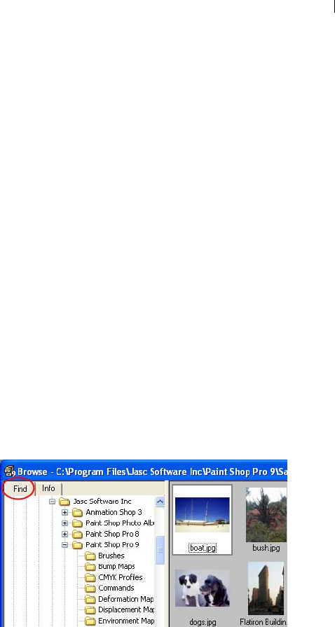
Chapter 3: Getting Images into Paint Shop Pro 47
2 Enter the search criteria and click Find Next or Find All to display
the search results in the Browser window.
To rotate files:
1 Select the files that you want to rotate.
2 Choose ImageFile > JPEG Lossless Rotation, and then choose an
option to rotate the selected files.
Using the Find Tab in the Browser
The Image Browser includes two tabbed panes on the left side, the
Find tab (for navigation) and the Info tab (for displaying image
information).
Use the Find tab's familiar Windows Explorer-like controls to
navigate to the folder containing the desired images. To use the tab:
1 If it is not already open, start up the Image Browser. The Find tab
will be the active tab.
2 Using the Windows Explorer-like interface, navigate to the folder
containing the desired images. Thumbnails of the folder's images
will appear on the right side of the window.
Note: To modify how the thumbnails are displayed, choose File >
Preferences > General Program Preferences (or right-click in the
workspace and choose General Program Preferences from the
context menu) and then choose the Browser tab. Make the desired
settings in this tab to affect the Image Browser.
Using the Info Tab in the Browser
Use the Info tab to display pertinent image information, such as
creator details as well as EXIF details for digital photos. To use the
tab:
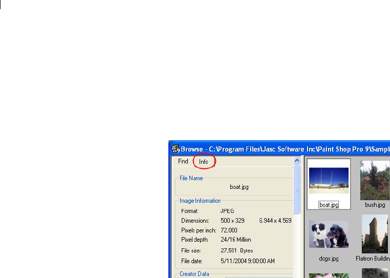
Chapter 3: Getting Images into Paint Shop Pro
48
1 If it is not already open, start up the Image Browser.
2 Click the Info tab located in the upper left portion of the Browser
window.
3 Click an image thumbnail to view its details in the Info tab. If
you're browsing digital camera images, the EXIF data associated
with the image will appear in the Details section of this tab.
Updating Thumbnails
When you open a folder in the Browser, Paint Shop Pro creates
thumbnails for all supported graphic images and stores them in a file
called PspBrwse.jbf. Every folder you have opened in the Browser
has a copy of this thumbnail file. Paint Shop Pro uses this file to
display thumbnails more quickly each time you open a folder.
The default preference setting is to have the thumbnails file update
automatically every time you open the folder. To change this
preference, use the Browser tab in the General Program Preferences
dialog.
Occasionally you may want to update the thumbnails with the
Update Thumbnails command. For example, if you have used
Windows Explorer to delete or add a file in a folder, you can choose
File > Update Thumbnails, or press F5 to update the thumbnails file.
(You can also open the folder again in the Browser for Paint Shop
Pro to update it automatically.)
After a thumbnail file is created, new files are appended to the end of
the thumbnails list. To sort the list alphabetically or by other
characteristics, choose File > Sort.

Chapter 3: Getting Images into Paint Shop Pro 49
Saving Image Files
Paint Shop Pro has a native .PspImage format that supports layers,
alpha channels, and other features you use to create images. You will
find it convenient to save an image in this format while you are
working on it and then convert it to a different format after you have
finished.
Using Autosave
You can use the Autosave feature to save your files automatically at
specified intervals. This can prevent you from losing your work if
your computer shuts down unexpectedly. For more information,
please refer to “Setting Autosave Preferences” on page 67.
Compressing a .PspImage File
An image file in the .PspImage format can be saved without
compression, or it can be compressed to save space. Both of the
compression methods that Paint Shop Pro uses are lossless, and
reduce the file size without losing any image information. Saving a
file without compressing it is the quicker method, but it requires
more hard disk space.
Paint Shop Pro uses two compression methods:
Run length encoding (RLE), which is fast and compresses most
multi-layered images to about 75% of their original sizes. It
works well with images that contain large areas of the same
color.
LZ77 compression, which is slower than RLE, but can compress
an image to a smaller size than RLE. It works well with photo-
realistic images.
Choose a compression option by clicking the Options button in the
various save dialogs.
Saving an Image
You can easily save an image with the same file name and location.
Note that this will overwrite the original image with the modified
image. To save the image using a different name or file format,
choose File > Save As.
Always save a .PspImage
version of your file
To be able to use all Paint Shop
Pro features, we recommend you
save and edit your files in
.PspImage format with a color
depth of 16 million colors. You can
then use the Save As or Export
command to save a copy of the file
in the desired output format. Your
original image stays intact in case
you need to make changes to it
later.
Chapter 3: Getting Images into Paint Shop Pro
50
To save an image:
To automatically save the image with the same file name and
location (overwriting the original image with the modified image):
Choose File > Save.
Press Ctrl + S.
Click the Save button on the toolbar.
Saving a New Image File
The first time you save an image, Paint Shop Pro automatically
opens the Save As dialog, where you select a location, name, and
format for the image. After this, Paint Shop Pro saves changes to the
original image without opening the dialog.
To save a new image:
1 Choose File > Save, press Ctrl + S, or click the Save button on
the toolbar to open the Save As dialog.
2 Use the Save In drop-down list to navigate to the folder in which
you want to save the image file. If you frequently save files to the
same folder, click the Favorites folder and select a folder
from the list.
3 In the File Name field, type a name for the file.
4 To save the file in a new format, select the format from the Save
As Type list.
5 If the file format has save options, click the Options button to
open the Save Options dialog. Select new settings, if appropriate.
If you are unsure of the settings, use the default values. Click OK
to return to the Save As dialog.
6 Click Save to close the dialog and save the file.
You can have Paint Shop Pro display the last used file type when
opening this dialog. Select this option in the Dialogs and Palettes
Preferences tab of the General Program Preferences dialog.

Chapter 3: Getting Images into Paint Shop Pro 51
Saving an Image File in its Original
Format
When you save an image and then edit it, the image title bar displays
a Modified tag (an asterisk) after the file’s name to indicate the file
has been modified. This tag disappears each time you save the file; it
reappears when you again edit the image.
Saving an Image in a New File Format
If you want to save a file in another format, use the Save As
command.
To save a file:
1 Choose File > Save As or press F12 to open the Save As dialog.
2 Navigate to and open the folder in which you want to save the
image file.
3 To rename the image file, type a new name in the File name field.
4 In the Save as type drop-down list, select a new format.
5 If the file format has save options, click the Options button to
open the Save Options dialog. Select new settings, if appropriate.
If you are unsure of the settings, use the default values. Click OK
to return to the Save As dialog.
6 Click Save to save the image file and close the dialog.
Saving a Copy of an Image
When you save an image using the Save Copy As command, you are
copying the original file, not saving it. Use this command to save a
version of a file without affecting the original. The dialog contains
all the same features as the Save As dialog.
Note
When using the Save Copy As command:
The modifier tag is not affected. It does not disappear from the
title bar.
The file name does not change. The copy is titled “Image Name.”
Paint Shop Pro saves the copy to the same directory and in the
same format that was last used with the Save Copy As command
(not the Save As command).

Chapter 3: Getting Images into Paint Shop Pro
52
To save a copy of an image:
1 Choose the File > Save Copy As or press Ctrl + F12 to open the
Save Copy As dialog.
2 Use the Save In drop-down list to navigate to a new folder if you
want to save the copy in a different folder. If necessary, use the
Up One Level button to help navigate, or the Create New Folder
button to create a new folder.
3 In the File Name box, type a name for the file.
4 To save the file in a different format, select the format from the
Save As Type drop-down list.
5 If the file format has save options, click the Options button to
open the Save Options dialog. Select new settings, if appropriate.
If you are unsure of the settings, use the default values. Click OK
to return to the Save As dialog.
6 Click Save to save a copy of the file.
Note
For information about saving several images in a new file format,
refer to Chapter 17.
For information about optimizing images for the Web, refer to
Chapter 19.
Closing Image Files
To close an Image, choose File > Close, or click the Close button
on the image window's title bar. If you haven't saved changes to the
image, you'll be prompted to do so.

53
Customizing Paint Shop Pro
By setting up Paint Shop Pro to appear and respond in ways that
best suit your work, you’ll not only create a better user experience,
but you’ll likely find yourself working faster and more efficiently.
This chapter describes the various ways you can customize Paint
Shop Pro.
Note
CMYK Conversion Preferences are covered in Chapter 16, Printing
Images.
Contents Using Custom Workspaces. . . . . . . . . . . . . . . . . . . . . . . . . . . . . 54
Customizing Toolbars and Menus. . . . . . . . . . . . . . . . . . . . . . . . 56
Setting General Program Preferences. . . . . . . . . . . . . . . . . . . . . 59
Setting Autosave Preferences . . . . . . . . . . . . . . . . . . . . . . . . . . 67
Setting File Locations . . . . . . . . . . . . . . . . . . . . . . . . . . . . . . . . 67
Setting File Format Preferences. . . . . . . . . . . . . . . . . . . . . . . . . 73
Setting File Format Associations . . . . . . . . . . . . . . . . . . . . . . . . 79
Resetting Application Preferences . . . . . . . . . . . . . . . . . . . . . . . 80
Assigning and Viewing Shortcut Keys . . . . . . . . . . . . . . . . . . . . . 81
Adjusting Monitor Display Options . . . . . . . . . . . . . . . . . . . . . . . 84
CHAPTER 4

Chapter 4: Customizing Paint Shop Pro
54
Using Custom Workspaces
The Paint Shop Pro workspace is made up of all the program’s
palettes, toolbars, and open images. You may find that the way you
arrange the workspace while editing photos may differ from your
arrangement for using the Web tools. Fortunately, Paint Shop Pro
allows you to save any number of workspace arrangements, allowing
you to load the specific workspace that best suits the work you
intend to do.
Saving Workspaces
When you save a workspace, Paint Shop Pro saves the information
in a .PspWorkspace file. The following information is stored:
Ruler, grid, and guide information
Menu, palette, and toolbar settings, locations, and docking status
Browser window position (if open)
Full screen edit mode status
Open images, including the images zoom levels and scroll bar
locations
Note: Workspace files do not include an actual copy of any open
images. Workspace files only reference the name and location of
an image. If you delete an image from your computer, it will not
display in a workspace.
To save the current workspace:
1 Choose File > Workspace > Save or press Shift + Alt + S to open
the Save Workspace dialog.
2 To save the workspace in a folder other than the program default
folder, click the File Locations button.
3 In the New Workspace Name field, type a name for the new
workspace.
4 Click Save.
If your workspace contains any modified images that you have not
saved, you will be prompted to save the changes to your image.
Choose from these options:
Yes Saves the image changes and saves the workspace.

Chapter 4: Customizing Paint Shop Pro 55
No Saves the workspace, but does not save the changes to your
image.
Cancel The workspace is not saved.
Loading Workspaces
To load a workspace:
1 Choose File > Workspace > Load or press Shift + Alt + L to open
the Load Workspace dialog.
2 Select the workspace file you want to load.
Note: To load a workspace not displayed in the dialog, click the
File Locations button and use the File Locations dialog to make
the desired workspace folder the active directory.
3 Click Load.
Workspace files do not include an actual copy of any open images.
Workspace files only reference the name and location of an image. If
you delete an image from your computer, it will not display in a
workspace.
If you had two windows open for the same image when you saved
the workspace, they both open again.
If an image from the workspace is already open, Paint Shop Pro
applies the workspace settings to the open image.
Deleting Saved Workspaces
To delete a saved workspace:
1 Choose File > Workspace > Delete or press Shift + Alt + D to open
the Workspace dialog.
2 Select the workspace file you want to delete.
3 Click Delete.
Quick Access to
Workspaces
Load a recently used workspace by
choosing it from the list of recent
workspaces located at the bottom
of the File > Workspace menu.

Chapter 4: Customizing Paint Shop Pro
56
Customizing Toolbars and Menus
Paint shop Pro 9 gives you almost total control over the program’s
toolbars, allowing you to:
Move commands from toolbar to toolbar.
Add almost any command to any toolbar.
Add your own custom scripts to toolbars (Refer to Chapter 17).
Create your own custom toolbar.
Customizing Toolbars
When you display the Customize dialog, the entire Paint Shop Pro
workspace transforms into customize mode. You can click and drag
almost any menu command or tool to any other menu or toolbar. You
can add or delete commands from the menus on the Menu Bar. All
this can be done with the Commands and Toolbars tabs of the
Customize dialog.
To access the toolbar customize mode:
1 To open the Customize dialog, choose View > Customize. You can
click back and forth between tabs to access the controls you need.
2 After making your changes, click Close.
To select which toolbars are displayed:
Choose View > Toolbars, and select the toolbar that you want to
display; or
Choose View > Customize to open the Customize dialog. Click
the Toolbars tab, and mark the checkbox for the toolbars that you
want to display, and then click Close.
To select which Menu Bar is displayed:
1 Click the Menu tab.
2 In the Application Frame Menus group box, select an option from
the Show Menus for drop down list:
Default This set of commands displays when no images are open.
Image This set of commands displays when images are open.
Browser This set of commands displays when the Browser is the
active window.
Right-click access to
Customize dialog
Another way to access the
Customize dialog is to right-click in
the Menu bar, Tool palette, or Tool
Options palette, and then choose
Customize from the context menu.

Chapter 4: Customizing Paint Shop Pro 57
To reset a Menu Bar:
1 Click the Menu tab.
2 In the Application Frame Menus group box, select the menu you
want to reset from the Show Menus for drop-down list.
3 Click the Reset button.
To move a command button or tool:
While in Customize mode, drag the item to another palette or
toolbar.
To add commands or tools to a toolbar:
1 Click the Commands tab of the Customize dialog.
2 From the Categories list, select a category. Paint Shop Pro groups
related commands into categories. For example, click the File
category to display all File menu commands. To list all Paint
Shop Pro commands at once, choose All Commands.
3 From the Commands list, click and drag a command to a toolbar.
To remove commands or tools from a toolbar
Drag the item to an empty workspace area or an empty area
outside a toolbar. Release the mouse button when you see the
cursor change to this shape: ; or
Right-click on the item and choose Delete from the context
menu.
To reset all toolbars:
1 Click the Toolbars tab.
2 Click the Reset All button. All toolbars will revert to the
program’s default settings.
To reset a specific toolbar:
1 Click the Toolbars tab.
2 In the Toolbars list, select the name of the toolbar to reset.
3 Click the Reset button. The selected toolbar will revert to the
program’s default settings.

Chapter 4: Customizing Paint Shop Pro
58
To add a separator to a toolbar:
1 Choose View > Customize to display the Customize dialog.
2 Right-click a button in the toolbar to which you’ll be adding the
separator, and then choose Include Separator from the context
menu that appears. This adds a separator to the left of the button
you clicked.
Note: To rearrange a button relation to the separator, hold down
Alt and drag the button to the desired location.
To delete a separator from a toolbar:
1 Choose View > Customize to display the Customize dialog.
2 Right-click the toolbar button directly to the right of the
separator. This displays the context menu. Notice the check mark
next to the Start Group item.
3 Select the Include Separator item to remove the check mark and
the separator.
Creating a New Toolbar
You can create a custom tool bar with your favorite commands and
tools.
To create a new toolbar:
1 Choose View > Customize to open the Customize dialog.
2 Click the Toolbars tab.
3 Click New to open the Toolbar name dialog.
4 Type a name for the new toolbar and click OK. You’ll see a small,
empty toolbar.
5 Drag this new toolbar off to the side of the Customize dialog so
you can see it better.
6 To add commands to it, choose the Commands tab in the
Customize dialog.
7 Under Categories, choose the menu containing commands you
want to load onto your custom toolbar.
8 Drag command icons into the new toolbar. Add separator bars, if
necessary, as described above.
9 When you’re done adding commands, click Close. Your custom
toolbar is now listed when you choose View > Toolbars.

Chapter 4: Customizing Paint Shop Pro 59
To delete a custom toolbar:
1 Choose View > Customize to open the Customize dialog.
2 Click the Toolbars tab.
3 In the Toolbars list, select the name of the custom toolbar you
want to delete.
4 Click Delete.
5 Click Close.
Customizing Context Menus
Context menus open when you right-click with a certain tool or
right-click over a certain area of the workspace.
To customize a context menu
1 Choose View > Customize to open the Customize dialog.
2 Click the Menu tab.
3 From the Select context menu drop-down list, choose a context
menu. The context menu will display in the workspace. Edit the
menu just like any other toolbar. For instructions see,
“Customizing Toolbars” on page 56.
Setting General Program Preferences
General Program Preferences define the behavior of various
features.
To set General Program Preferences:
1 Choose File > Preferences > General Program Preferences to
open the Paint Shop Pro Preferences dialog.
2 Click the tab containing the preference information you want to
change.
3 Modify the desired settings, and then click OK.
Undo Preferences
The Undo tab controls some settings of the Undo and Redo
commands, as well as one setting for the History palette

Chapter 4: Customizing Paint Shop Pro
60
Undo and Redo Settings
To enable Paint Shop Pro to undo actions, mark the Enable the undo
system check box. This enables you to set all the items in this area of
the Undo tab.
When the undo system is active, you can set the following options:
Limit undo/redo disk usage to n MBytes of storage per open
image Sets the maximum amount of disk space each images
undo/redo steps can use.
Limit undo/redo to n steps per open image Sets the number of
undoable/redoable steps in each open image. The default value is
250. Steps older than 250 will become undoable steps, only 10 of
which will be retained as defined by the Non-undoable steps after
last undoable step setting.
Compress undo/redo information Marking this check box saves
disk space, but slows down undo and redo operations.
Enable the redo system Activates the Redo command, allowing
you to redo actions you have undone.
History Palette Setting
n Non-undoable steps after last undoable step Sets the number
of non-undoable steps that will be retained after the last non-
undoable step limit has been reached. The default value is 10.
View Preferences
The View tab controls some image window behaviors.
Zooming
These options determine if Paint Shop Pro automatically resizes an
image window when you zoom in or zoom out. A window is resized
to include as much of the image as will fit.
New Images
Auto size With this check box marked, Paint Shop Pro automatically
zooms out to fit the entire image in the window if you open an image
that is too large to fit in its image window.

Chapter 4: Customizing Paint Shop Pro 61
After Changing Size
Fit window to image check box is selected, Paint Shop Pro
automatically resizes the image window whenever you resize an
image.
Auto Size With this check box marked, if you increase an image’s
size to more than can fit in its window, Paint Shop Pro reduces the
image’s magnification accordingly.
Display and Caching Preferences
The Display and Caching tab controls presentation and caching.
Presentation Options
Re-use last type in save-as dialog When you mark this check
box, the last file format used to save an image automatically
appears in the Save as type field.
Display all color dropper ToolTips Clear this box to hide the
color information that appears next to the dropper tool when it is
positioned over a color.
Use precise cursors Mark this check box to use a cross hair for
tool cursors instead of the tool’s icon.
Show brush outlines Clear this check box to hide the outline
(shape, size) of the current brush as the cursor moves over an
image.
Thumbnail/Preview Enter a size for the thumbnails in the Effects
Browser and the preview images that display in the Layers
palette.
Zoom/Rescaling Quality Adjust the slider between Faster and
Better. Faster will zoom images faster, but will display less fine
detail. Better will zoom images more slowly, but display more
fine detail.
Caching Options
These options allow for faster image redraws after you make
changes. By default, they are all marked. Turning these options off
will likely slow image redraws.
In the Image group box:
Merged Image Clear this check box to stop saving an image cache
of your entire merged image.
About color pickers
In previous versions of Paint Shop
Pro, you could use the Jasc Color
Picker or the Windows Color
Picker. In Paint shop Pro 9, the
Windows Color Picker is not
available.

Chapter 4: Customizing Paint Shop Pro
62
Merged Below Active Layer Clear this check box to stop saving
an image cache of all the layers below the active one.
Group Layers Options
Merged Group Clear this check box to stop saving an image
cache of the merged image for each group.
Merged Below Active Layer Clear this check box to stop saving
an image cache of all the group layers below the active one.
Palettes Preferences
The Palettes tab controls behaviors of the materials palette as well as
how palettes dock.
Materials Palette Options
Display colors in RGB format or Display colors in HSL format
This option controls the color information that appears in the
materials palette and with the dropper tool.
Decimal display or Hexadecimal display
This option controls how color values will display throughout the
program.
Show rainbow picker or Show document palette
For images with limited palettes (8-bit, 256 color), the document
palette shows only colors that are actually in the image.
Docking Options
Clear the check box beside each palette to prevent the palette
from docking. This will allow you to drag the palette anywhere in
the workspace.
Browser Preferences
The Browser tab controls the appearance and operation of the
Browser.
Thumbnail Size
Enter values (in pixels) for the thumbnail size the Browser
displays. The size range is from 50 to 150 pixels. Clear the
Symmetric check box to adjust thumbnail width and height
independently.
Why use hexadecimal?
Web browsers use the
hexadecimal format to specify
colors.

Chapter 4: Customizing Paint Shop Pro 63
Appearance
Choose Use Windows colors to highlight thumbnails with the
current Windows selection color. Or, choose Use classic colors
and choose a thumbnail highlight color form the Selection color
box.
Clear the Display flat style thumbnails check box to display
thumbnails that look like raised button bars.
Other Options
Display tooltips over thumbnails Clear this check box to hide the
image information that appears when the cursor is over
thumbnails.
Save browser files to disk Clear this check box to stop the
Browser from creating a cache file in folders you browse. By
default, when you view a folder using the Browser, Paint Shop
Pro saves a file called pspbrwse.jbf in that folder. This cache file
allows you to view the thumbnails more quickly the next time
you browse the folder.
Automatically update the thumbnails Mark this check box to
automatically update a folder’s cache file every time the folder is
browsed. When you view a folder with the Browser, the Browser
displays the contents of the folder’s cache file. If you make
changes to the images in the folder, the thumbnails will not show
the results unless the cache file is updated.
File Format Exclusions Click this button (located in the lower
right corner of the Browser preferences tab) to display a dialog
allowing you to exclude selected file formats from appearing in
the browser.
Units Preferences
The Units tab controls ruler options and the default resolutions for
new images.
Rulers
Choose a measurement system for the rulers from the Display
units drop-down list.
Choose Toolbar colors to have the ruler color match
Paint Shop Pro’s toolbars or choose Black on White rulers.
Color choice tip:
Right-click the Selection color
box to pick from the Recent
Colors dialog.
Grid Preferences
To set grid preferences, see
Chapter 6, Editing Images.

Chapter 4: Customizing Paint Shop Pro
64
Default Resolution
Choose a measurement system from the drop-down list and enter
the default resolution for new images. You can override this
resolution on an image-by-image basis by modifying the settings
in the New Image dialog.
Vector Coordinates
When this check box is marked, objects will snap to the center of
pixels while they’re moving. You will have to zoom in very far to
see this.
Transparency and Shading Preferences
The Transparency and Shading tab controls the grid size and color
representing transparent backgrounds and transparent areas of
layers. Additionally, this is where you set the color and opacity of
the Crop shading area.
Setting Transparency Options
Grid size Chose one of the four grid sizes from the drop-down
list.
Grid Colors Choose a color scheme from the Scheme drop-down
list. To customize the grid colors, click inside the Color 1 or
Color 2 boxes and select new colors.
Preview displays your proposed changes to the transparency grid.
Setting Crop Shading Options
Enable crop shading area Mark this check box to activate
shading outside the crop rectangle.
Color Click inside the Color box to choose a shading area color.
Opacity Use the Opacity setting to control how opaque the
shading area color will be.
Warning: When crop shading is enabled and you attempt to crop an
8-bit (256 colors) or less image, the area outside the crop rectangle
will be black. Thus when cropping these types of images, you may
want to disable this option.
Color choice tip:
Right-click the Selection color
box to pick from the Recent
Colors dialog.

Chapter 4: Customizing Paint Shop Pro 65
Warnings Preferences
The Warnings tab controls how warning dialogs will display.
By default, Paint Shop Pro displays a warning dialog whenever you
are about to perform an operation that will result in lost information
or one that can not be applied to the image in its current state.
To prevent a warning from appearing, clear the check box in
front of its description.
Click the Enable All button to mark all the check boxes in the list.
Click the Disable All button to clear all the check boxes in the
list.
Photo Sharing Preferences
The current photo sharing service provider is shown in the Select a
photo sharing service list. When you choose File > Export >
PhotoSharing, that provider’s site will be accessed via your Web
browser.
Auto Action Preferences
Common actions that need to be performed in order to further edit an
image can be automated.
For example, you can only apply effects to 24-bit images. However,
most of the Effects menu items are active even if the active image is
8-bit. When you select an effect in an 8-bit image, the Auto Actions
dialog opens telling you Paint Shop Pro must convert the image to
24-bit to proceed with the effect.
To set the preferences for an Auto Action:
1 Select an Auto Action from the Auto Action Prompt list.
2 Choose one of these options for each action:
Never Prevents the action from happening. Choosing Never will
make certain menu commands inactive if an Auto Action is
required to complete the command. Note that some items in the
list do not have this option available.
Always Performs the action silently (without prompting you).
Prompt Asks if you want to perform the action.

Chapter 4: Customizing Paint Shop Pro
66
Set all the actions in the list to a certain option by clicking
Always All, Never All, or Prompt All.
Reset all the actions in the list to the program’s default settings by
clicking Reset.
Miscellaneous Preferences
The Miscellaneous tab controls a variety of preferences.
Recently used file list Set the maximum number of files that will
appear when you choose File > Recent Files. For example, if the
value is set to four, only the last four saved files will appear on
the list.
Note: You must restart Paint Shop Pro before the new settings
will take effect.
Tolerance to background color when pasting a transparent
selection When you paste data as a transparent selection, Paint
Shop Pro adds it to the current image, defines it as a selection,
and then deselects all the pixels that match the current
background color. The tolerance value you enter determines how
closely the background color must match the transparent color
for it to become transparent. The tolerance scale is 0% to 200%.
Zero percent indicates that only image pixels with a perfect
match to the current background color are made transparent.
200 percent indicates that all image pixels are made
transparent.
Clipboard Data on Exit Choose how Paint Shop Pro will handle
any clipboard data when you exit the program.
Ask Whenever you exit, Paint Shop Pro will ask you what to
do with the clipboard data.
Delete Clipboard data will be deleted on exit.
Leave Data will remain in the clipboard on exit.
Force full window redraw when positioning image elements
Mark this check box to redraw the information in the active
window whenever you move objects in the image.
Show splash screen when application starts Clear this option to
hide the Jasc Software, Inc. splash screen which appears at
program startup.

Chapter 4: Customizing Paint Shop Pro 67
Disable pressure support for puck-type pointing devices Mark
this check box to turn off the pressure sensitive features of puck-
type pointing devices included with graphics tablets.
Setting Autosave Preferences
Paint Shop Pro can automatically save all open images on a set
schedule. These autosaved files can help you recover your work if
your computer crashes. When Paint Shop Pro starts after a crash, it
will open any autosaved files it finds.
Note
To find where Paint Shop Pro saves the autosaved files, select
File > Preferences > File Locations and select the
Undo/Temporary Files folder from the File Type list.
To set the autosave preferences:
1 Choose File > Preferences > Autosave Settings to open the
Autosave dialog.
2 Set the options:
Enable autosave Mark this check box to activate the autosave
feature.
Minutes Set the number of minutes between each autosave.
Setting File Locations
Paint Shop Pro resources include such items as scripts, picture tubes,
patterns, gradients, displacement maps, and workspaces. The full
listing of resources displays along the left side of the File Locations
dialog. Paint Shop Pro saves and searches for resources in several
default folders on your computer. By changing File Locations
preferences, you can change where Paint Shop Pro looks for and
saves these resources. You can also control how plug-ins are used
and which Web browsers are used to preview your images.
Note: By default, all new files you create are saved in the
appropriate folder of the ...My Documents\My PSP Files folder.
Most default program resources are stored in the appropriate folder
in the path ...\Program Files\Jasc Software Inc\Paint Shop Pro 9.

Chapter 4: Customizing Paint Shop Pro
68
Editing File Locations
The File Locations dialog controls where Paint Shop Pro looks for
and saves important files.
Changing File Locations
You can change where Paint Shop Pro to stores and retrieves specific
resources.
To change file locations:
1 Choose File > Preferences > File Locations to open the File
Locations dialog.
2 From the File types list on the left side, select the resource that
you want to change file locations for.
3 At the top of the dialog's right side you'll see the default folders
where the specified resource can be saved to.
Add Select a listed folder and then click this button (or click the
Browse for Folder button at the end of the selected folder) to add
another folder to the list. This will display the Browser for Folder
dialog, allowing you to navigate to and select another folder. To
create a new resource folder, click the Browse for Folder dialog's
Create New Folder button and then enter the folder name.
Remove Select a listed folder and then click this button to
remove the folder for the current resource category.
Select a folder and then click this button to move the folder
up the list.
Select a folder and then click this button to move the folder
down the list.
4 Use the options in the Folder options section to enable the folder
system as well as the subfolders. When these items are
unchecked, Paint Shop Pro will not be able to search for folders
and their subfolders.
5 In the Save to field, click the drop list and then click on the folder
where you want the current resource saved to.
6 Click OK to save your settings and return to Paint Shop Pro.
Important: To create a custom category for a particular resource,
Refer to the Creating a Custom Category section in this chapter.
Edit Paths: another way to
view file locations
You can open the File Locations
dialog by clicking the Edit Paths
button which appears in many
Paint Shop Pro dialogs.

Chapter 4: Customizing Paint Shop Pro 69
Using the Resource Manager Dialog
Paint Shop Pro resources include such items as scripts, picture tubes,
patterns, gradients, displacement maps, and workspaces. The full
listing of resources displays along the left side of the File Locations
dialog. Using a consistent method for managing these resources can
make your workflow easier. This is where the Resource Manager
dialog comes in.
Accessing the Resource Manager Dialog
Wherever you find a Presets control (such as in the Tool Options
palette's Presets drop list for any tool, or in the Presets drop list for a
dialog), or the visual resource drop-list for resources such as Preset
Shapes, Gradients, etc., you'll find the Resource Manager button
. Click this button to access the Resource Manager dialog.
Deleting a Resource
1 If necessary, from the Category drop-list choose the category where
the resource resides.
2 Click the resource from the list.
3 Click the Delete button. You'll be prompted to verify that you
wish to proceed.
4 Click Yes to delete the resource.
Renaming a Resource
1 If necessary, from the Category drop-list choose the category where
the resource resides.
2 Click the resource from the list.
3 Click the Rename button. The Rename Resource dialog appears.
4 Enter the new name for the resource and then click OK.
Copying a Resource to Another Location
1 If necessary, from the Category drop-list choose the category where
the resource resides.
2 Click the resource from the list.
3 Click the Copy button. The Save As dialog appears.
Note: At this point, you could also rename the file via the Save
As dialog's File Name field.

Chapter 4: Customizing Paint Shop Pro
70
4 Navigate to the folder where you want to move the resource, and
then click Save.
Moving a Resource to Another Location
1 If necessary, from the Category drop-list choose the category where
the resource resides.
2 Click the resource from the list.
3 Click the Move button. The Browse for Folder dialog appears.
4 Navigate to the folder where you want to move the resource, and
then click OK.
Note: If you move the resource to a location not currently listed in
the File Locations dialog, you won't see the resource in the visual
resource drop-list, nor in the Resource Manager dialog.
Creating a Custom Category
Create your own categories that will appear for a given resource as
follows:
1 Access the File Locations dialog using one of the following
methods:
Choose File > Preferences > File Locations; or
From the Presets area of a dialog, or Presets area of the Tool
Options palette, or from a resource's visual drop-list, click the
File Locations button.
2 In the File types list on the left side of the dialog, click the
resource for which you wish to create a new category folder.
3 In the File folders list, click once on the folder under which the
sub folder will reside.
4 In the Folder Options area of the File Locations dialog, make
sure the Enable and Use sub folders check boxes are marked, and
then click the Create Sub Folder button. This displays the Enter
Name dialog.
5 Enter a name for the sub folder, and then click OK to close the
Enter Name dialog.
6 (In the Save to field toward the bottom of the File Locations
dialog, note that the category you created automatically becomes
the folder where new resources of that type will be saved.) Click
OK to close the File Locations dialog.

Chapter 4: Customizing Paint Shop Pro 71
To have the new category appear in the Categories drop-list, you
must first save a resource in the folder you just created, or use the
Copy or Move buttons described above to place a resource file in the
new folder.
Setting Plug-in Locations
Paint Shop Pro allows you to use Adobe compatible plug-ins. Use
the File Locations dialog to choose folders containing plug-ins and
control how plug-ins are used.
To control plug-in functions:
1 Choose File > Preferences > File Locations to open the File
Locations dialog.
2 From the File types list, select Plug-ins.
3 Set these options:
Enable plug-ins Mark this box to allow Paint Shop Pro to use
plug-ins.
Limit Loaded plug-in files to those with an .8B* extension
The .8B* extension is the most common plug-in extension. Clear
this check box to load plug-ins with other extensions.
Allow file format plug-ins to request pre-filtering of support file
types Some plug-ins can open files that Paint Shop Pro also
supports. Mark this check box to allow a plug-in to try to open
(pre-filter) the file before it opens in Paint Shop Pro.
To add plug-in locations:
1 Choose File > Preferences > File Locations to open the File
Locations dialog.
2 From the File types list, select Plug-ins.
3 Click the Add button. The Browse for Folder dialog appears.
4 Type the full path name of the folder you want to add and click
OK. This takes you back to the File Locations dialog.
5 Make sure the Enable option is checked in the Folder Options
section of the File Locations dialog, and then click OK.

Chapter 4: Customizing Paint Shop Pro
72
Selecting a Web Browser
Paint Shop Pro allows you to preview your images with Web
browsers. Use the File Locations dialog to select which browser(s)
to use.
To delete or edit Web browsers:
1 Choose File > Preferences > File Locations to open the File
Locations dialog.
2 From the File types list, select Web Browsers.
3 Select a browser from the list.
4 Click Edit to change the browsers location or Delete to remove
the browser from the list.
5 Click OK.
To add Web browsers:
1 Choose File > Preferences > File Locations to open the File
Locations dialog.
2 From the File types list, select Web Browsers.
3 Click Add to open the Browser Information dialog.
4 Type the full path name of the Web browser you want to add or
click the Browse button to find and select the program.
Type a different name in the Web Browser Name field if desired
and Click OK.
5 Click OK.
Another way to select Web
browsers:
Select View > Preview in Web
Browser to open the Preview in
Web Browser dialog. Click the Edit
Web Browser button.

Chapter 4: Customizing Paint Shop Pro 73
Setting File Format Preferences
With File Format Preferences, you can specify how Paint Shop Pro
handles images in the following formats: Windows Metafile, Kodak
PhotoCD, PNG, PostScript, RAW Graphics, and Raw Camera Data.
Setting Raw Camera Data Preferences
To better support the prosumer digital camera user, Paint Shop Pro 9
now supports Raw camera data images. These images contain
unprocessed sensor data captured by high-end digital cameras from
Canon, Fuji, Kodak, Minolta, Nikon, Olympus, and Pentax.
Raw Camera Data Images vs. RAW (Graphics) File
Format Images
In order to avoid confusion, be aware that there is quite a difference
between Raw (unprocessed) camera data images and images in the
RAW graphics file format.
Raw Camera Data Images
This help topic focuses on Raw camera data images produced by
high-end digital cameras. The data from these images in no way
resembles or responds like RAW graphics image data.
RAW (Graphics) File Format Images
RAW graphics images are basic raster data format images with no
compression, and may include an optional non-standard header
which is not supported by Paint Shop Pro. These graphics images are
used primarily by game developers and by the scientific community.
Game developers use RAW graphics images for custom image
texturing, bumpmapping, and shading. The scientific community
uses these images for custom application-based image analysis.
Paint Shop Pro is used not only to create and edit RAW graphics
images, but also to provide conversion from standard formats (such
as TIF, JPEG, or TGA) into the RAW graphics format.
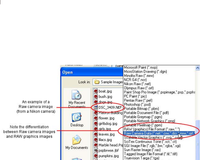
Chapter 4: Customizing Paint Shop Pro
74
Opening Raw Camera Data Images and RAW
Graphics Images
When you choose File > Open, and then check the options in the
Open dialog's Files of type field, you'll notice that RAW graphics
files are differentiated from Raw camera data images as shown here.
Setting Raw File Format Options
You may want the option of displaying a separate dialog for setting
sharpening, white balance, and exposure levels before the Raw
camera images open in Paint Shop Pro. Do this in the Raw Camera
Data tab of the File Format Preferences dialog.
1 Choose File > Preferences > File Format Preferences.
2 Click the Raw Camera Data tab.
3 Make sure the Prompt for override settings each time a raw
camera format is opened check box is marked.
4 Click OK to close the File Format Preferences dialog.
Now when you now attempt to open a Raw camera data image, the
Raw Camera Data dialog will appear, allowing you to override the
camera settings.
If this check box is not marked, the Raw Camera Dialog will not
appear prior to opening a Raw camera image.
Chapter 4: Customizing Paint Shop Pro 75
Using the Raw Camera Data Dialog
1 If necessary, use the zoom in and zoom out buttons to modify the
image preview, and use the Pan button to determine what portion of
the image is shown in the preview area. You can also use one of the
Zoom level presets from the drop-list. To set the image zoom level
to 100 percent, click the button.
2 If you want to rotate the image, use the Rotate Left and Rotate
Right buttons to rotate in 90-degree increments.
3 If you expand the size of the dialog, click the button to
proportionally scale the image to fit the new window size.
4 The Sharpen Mode setting controls the contrast between adjacent
image pixels. Be aware that applying sharpening may introduce
noise in the image. Click the Sharpen Mode drop list and choose
a setting:
Low: applies a minor level of sharpening.
Normal: applies a moderate level of sharpening -- in some case
this may introduce image noise.
High: applies a high level of sharpening -- may introduce image
noise.
Standard: this is the camera-specific default level of sharpening.
Off: no sharpening will be applied.
5 The White Balance settings provide options for correcting the
color cast certain types of lighting may cause. If the photo was
shot indoors in fluorescent lighting, for example, and the camera
was set for outdoor lighting conditions, the photo may have a
green color cast. In this case, you could choose Fluorescent to
correct this problem. Click the White Balance drop list and
choose a setting:
As Shot: uses the camera settings enabled when the photo was
taken.
Incandescent: applies correction for a photo taken in
incandescent light.
Fluorescent: applies correction for a photo taken in fluorescent
light.
Sunny: applies correction for a photo taken in sunlight.
Cloudy: applies correction for a photo taken in cloudy conditions.
Shade: applies correction for a photo taken in the shade.
Flash: applies correction for a photo taken with camera flash.

Chapter 4: Customizing Paint Shop Pro
76
6 Use the Exposure compensation numeric edit control to set an
exposure value. (The default value is 1.0.) The values range from
-2.0 to 2.0; lower values will darken the image, while higher
values will lighten the image.
7 When you're satisfied with the settings, click OK to open the Raw
camera image into the Paint Shop Pro workspace.
Setting Kodak PhotoCD Preferences
The Kodak PhotoCD format (PCD) is used by many photo
developers. This format can provide multiple image resolutions in
one file.
To set PCD file format preferences:
1 Choose File > Preferences > File Format Preferences to open the
File Format Preferences dialog.
2 Click the PCD tab.
3 Choose:
A default resolution setting. For example, 1536 x 1204 pixels.
Ask when loading each file PSP will ask you to pick a default
resolution each time you open a PCD file.
4 Click OK.
Setting Postscript File Preferences
Paint Shop Pro can read PostScript files (including multi-page files)
through level 2 and open them as raster images. When converting,
Paint Shop Pro can anti-alias objects and retain transparency
information.
To set PostScript file import preferences:
1 Choose File > Preferences > File Format Preferences to open the
File Format Preferences dialog.
2 Click the PostScript tab.
3 Choose a prompt setting:

Chapter 4: Customizing Paint Shop Pro 77
Prompt for size and options each time a PostScript file is opened
When you mark this check box, Paint Shop Pro will ask you to
choose settings for each PostScript file you open. Clear this
check box to use the Size and Options when not prompting
settings for all opened PostScript files.
4 If necessary, choose non-prompting options:
Resolution Set the resolution for the converted raster image
Image mode Select a mode from the drop-down list.
Page Size Select a page size from the drop-down list.
By default, if a PostScript file has a bounding box, the program
will match the canvas size to the bounding box.
Landscape Mark this check box to switch the page orientation to
landscape. The default is portrait. This option does not rotate
your images; only use this option for landscape PostScript files.
Anti-aliasing Mark this box to anti-alias PostScript objects as
they are converted to raster images.
Render transparency Clear this check box to use a white
background instead of the default transparent background.
Setting RAW Graphics File Preferences
Paint Shop Pro can read and save RAW graphics image formats. This
format (which is not to be confused with Raw Camera Data images)
is commonly used in graphics images in the scientific and computer
gaming industries.
To set RAW graphics file preferences:
1 Choose File > Preferences > File Format Preferences to open the
File Format Preferences dialog.
2 Click the RAW (Graphics) tab.
3 Set the Save options:
Header size Sets header size of the file.
Flip top and bottom Mark this box to flip the image upside down.
4 Set the 24 bit options:
RGB order or BGR order Choose the color order.
Planar mode Clear this box to turn off planar mode.

Chapter 4: Customizing Paint Shop Pro
78
Setting Metafile Preferences
Windows Meta File (WMF) is the Microsoft Windows native vector
format.
To set WMF image preferences:
1 Choose File > Preferences > File Format Preferences to open the
File Format Preferences dialog.
2 Click the Metafile / Import tab.
3 Choose from the two Load options:
Prompt for size and options each time a file is opened When you
choose this option, Paint Shop Pro will ask you to choose settings
for each WMF image you open.
Use file header information when available Some WMF files
have a file header containing default size information. Choose
this option to use the file header default size (if available). If you
open a file without a header, the size defaults to the values you
type in the Default size when file header is not available group
box.
4 Choose the following options:
Import vector data Mark this check box to import WMF vector
data as objects you can edit with vector tools. Clear this check
box to convert all vector objects to raster images.
Apply smoothing Mark this check box to smooth curved
polylines (vector data only).
Setting PNG Preferences
Set preferences for opening and saving PNG files as described
below.
1 Choose File > Preferences > File Format Preferences. The File
Format Preferences dialog appears.
2 Click the PNG tab.
3 Mark the Load and Save transparency to/from Alpha channel
option to enable feature for PNG files.

Chapter 4: Customizing Paint Shop Pro 79
Setting File Format Associations
File format associations control how Paint Shop Pro will interact
with many types of file formats.
Adding and Removing Associations
You can have certain file formats automatically open in Paint Shop
Pro. For example, when you associate the JPEG file format with
Paint Shop Pro, all JPEG files will open in Paint Shop Pro when you
double-click them from the Windows desktop. The associated JPEG
files will also display Paint Shop Pro icons.
To associate a file with Paint Shop Pro:
1 Choose File > Preferences > File Format Associations to open the
File Format Associations dialog. Do any of the following:
To associate a specific file format, mark the format’s check
box.
To associate all listed formats, click the Select All button.
To associate all listed formats that are not already associated
with other applications, click the Select Unused button.
To associate no file formats with Paint Shop Pro, click the
Remove All button.
2 Click OK.
Note
To add or remove file extensions you want associated with the
selected format, see “Changing File Format Extensions” below.
Changing File Format Extensions
Note
File format extension changes will not take effect until the next time
you start Paint Shop Pro.
To set file extensions:
1 Choose File > Preferences > File Format Associations to open the
File Format Associations dialog.
2 Select the file format that contains the extensions you want to
set.
What if I want to open a file
in another program?
When you associate a file format
with Paint Shop Pro, you can still
open that format in other
programs. Just use the other
program’s Open command.

Chapter 4: Customizing Paint Shop Pro
80
3 Click the Extensions button to open the Extensions dialog. The
preferred extension (the extension that Paint Shop Pro will use to
save files) is at the top of the list.
4 Do one of the following:
To add a file extension, click the Add button. Type in the new
extension and click OK.
Note: File extensions that have been associated with Paint
Shop Pro will have an asterisk (*) after the name.
To delete a file extension, select the extension from the list
and click Delete.
To reset a format to its default extension(s), select the
extension from the list and click Reset.
To make an extension the preferred choice, select the
extension and click Preferred. The extension will move to the
top of the list.
5 Click OK.
Resetting Application Preferences
Various program preferences can be reverted back to their defaults.
To reset application preferences:
1 Choose File > Preferences > Reset Preferences to open the Reset
Application dialog.
2 Select from these choices:
Reset general preferences Mark this check box to reset all
general program preference settings to the program defaults.
Reset file locations Mark this check box to reset all file location
settings to the program defaults.
Reset workspace to default configuration Mark this check box to
reset the current workspace to the program defaults.
Reset dialog positions and last used settings When you mark
this check box, any dialogs that open will appear in their default
locations. Also, Paint Shop Pro will forget the last settings you
used in all dialogs.

Chapter 4: Customizing Paint Shop Pro 81
Delete all cache files Mark this check box to delete (reset) all
existing cache files. Paint Shop Pro saves cache files on your
computer to improve program performance. Cache files can
become corrupted by computer errors.
Make all toolbars/palettes visible and on screen Mark this check
box to view all toolbars and palettes.
3 Click OK.
Assigning and Viewing Shortcut Keys
You can view existing keyboard shortcuts, assign a keyboard
shortcut to menu commands, bound scripts, and tools, and even
modify keyboard shortcuts.
To assign shortcut keys to commands and tools:
1 Choose View > Customize to open the Customize dialog.
2 Click the Keyboard tab.
3 In the Set Accelerator for drop-list, pick which application’s
shortcuts you want to assign. Choose Default (for Paint Shop
Pro’s main workspace) or Browser (for when the Image Browser
is active)
4 In the Category drop-list, select a category. Paint Shop Pro
groups related commands into categories. For example, if you
pick the File category, all the commands in the file menu are
displayed. To list all commands at once, choose All Commands.
5 In the Command list, select a command name.
6 The description of the command and any assigned shortcut keys
are displayed.
7 Click in the Press New Shortcut Key field.
8 Press the new keyboard shortcut you want to assign to the
command. The shortcut will appear in the Press New Shortcut
Key field. If the shortcut is already assigned to another
command, this will display above the field.
9 Click Assign to assign the new shortcut to the selected command.
10 Assign more shortcut keys, or click Close.
To assign a shortcut key to a bound script:
1 Choose View > Customize to open the Customize dialog.

Chapter 4: Customizing Paint Shop Pro
82
2 Click the Keyboard tab.
3 In the Set Accelerator for drop-down list, pick which
application’s shortcuts you want to assign. Choose Default (for
Paint Shop Pro’s main workspace) or Browser (for when the
Image Browser is active).
4 In the Category drop-list, select Bound Script. (Note that the
Bound Scripts that appear in the Commands list match what
appears in the Bound Scripts list of the Scripts tab.)
5 In the Commands list, select the bound script to which you want
to assign a keyboard shortcut.
6 Click in the Press New Shortcut Key field.
7 Press the new keyboard shortcut you want to assign to the bound
script. The shortcut will appear in the Press New Shortcut Key
field. If the shortcut is already assigned to another command, this
will display above the field.
8 Click Assign to assign the new shortcut to the selected bound
script.
9 Assign more shortcut keys as described above, or click Close.
To view all shortcut keys:
1 Choose Help > Keyboard Map to open the Help Keyboard dialog.
2 In the Show Accelerator for drop-down list, pick which
application’s shortcuts you want to view. Choose Default (for
Paint Shop Pro’s main workspace) or Browser (for when the
Image Browser is active)
3 In the Category drop-down list, select a category. Paint Shop Pro
groups related commands into categories. For example, if you
pick the File category, all the commands in the file menu are
displayed. To list all commands at once, choose All Commands.
The commands and their shortcut keys are displayed in the list,
sorted by command name. Click any column heading (Command,
Keys, or Description) to sort alphabetically by that column.
Note: To print the list of the current category of shortcut keys,
click Print in the Keyboard Map dialog’s toolbar. To select
commands and copy their information to the clipboard, click
Copy .
4 When you are finished viewing keys, click the Close button in
the upper right corner of the dialog’s title bar.

Chapter 4: Customizing Paint Shop Pro 83
To modify a keyboard shortcut:
1 Choose View > Customize to open the Customize dialog.
2 Click the Keyboard tab.
3 In the Category drop-list, choose the menu associated with the
command, script, or tool for which you want to modify the
keyboard shortcut.
4 In the Commands list, click the item for which you want to
modify the keyboard shortcut.
5 In the Current Keys field, click once on the shortcut to highlight
it, then click the Remove button located along the bottom of the
dialog.
6 Click inside the Press New Shortcut Key field so the cursor is
blinking, and then press the desired keyboard keys you wish to
assign as the new shortcut. (For example, hold down the Alt key
and press Q; you'll then see Alt + Q in the Press New Shortcut
Key field.) If the keyboard combination you entered is already
assigned, this will be displayed above this field. If the keyboard
combination is not assigned, you'll see "Assigned to: " above this
field. If you make a mistake entering the keyboard combination,
just start over with the correct key since pressing Delete or
Backspace will not erase what you entered.
7 When you're ready to assign the keyboard combination, click
Assign.
8 Click Close to close the Customize dialog.
Adjusting General View Options
The Menu and Options tabs of the Customize dialog control a
variety of general menu and toolbar features.
Menu Tab
Menu animations Choose an animation style for menu opening
and closing from the drop-down list.
Menu icons Clear this check box to hide the Menu Bar icons.

Chapter 4: Customizing Paint Shop Pro
84
Options Tab
Toolbars and Palettes
Show Screen Tips on toolbars Clear this check box to hide the
ToolTips that appear over tools and buttons.
Show shortcut keys in Screen Tips Clear this check box to hide
the shortcut key (if available) that appear in ToolTips.
Large icons Mark this check box to display larger toolbar icons.
Use Quadrant Rollups Mark this check box to have floating
palettes roll up toward the nearest quadrant of the workspace.
Personalized Menus and Toolbars
Menus show recently used commands first Mark this check box
to have Paint Shop Pro simplify its menus to show only recently
used commands. You can expand the menus by clicking the
expansion button.
Show full menus after a short delay If menus are only showing
the most recent items, all items will appear in a moment.
Reset my usage data Click this button to erase the memory of
your recently used menu commands.
Adjusting Monitor Display Options
Calibrating Your Monitor
To get the best results when working with Paint Shop Pro, you need
to properly calibrate your monitor. Calibrating the monitor improves
image quality and allows others to view your images as you intend.
To calibrate your monitor, you need an on-screen aid that helps you
adjust the monitor’s brightness and contrast. The Jasc Web site
provides an on-screen aid as well as detailed instructions for
calibration. Go to the Support section of www.jasc.com.
How often should I calibrate
my monitor?
Monitor performance can change
over time, so it’s best to calibrate
your monitor every few months.

Chapter 4: Customizing Paint Shop Pro 85
Adjusting the Monitor Gamma Setting
Paint Shop Pro’s monitor gamma setting adjusts how colors display
in Paint Shop Pro. This setting does not affect how your monitor
displays colors in other applications.
Most users should not adjust the monitor gamma setting. If you
make color corrections after you change the monitor gamma, the
colors may look distorted on other monitors or in applications other
than Paint Shop Pro.
To adjust the monitor gamma:
1 Choose File > Preferences > Monitor Gamma to open the Monitor
Gamma Adjustment dialog.
2 Lean away from your monitor and look at the red, green, blue,
and grey rectangles. Each color contains an inner, solid color
rectangle and outer, patterned rectangles. On a correctly adjusted
monitor, the inner rectangles are difficult to distinguish from the
outer rectangles.
3 Do one of the following:
To adjust the red, green, and blue values in unison, mark the
Link channels check box.
To adjust the values individually, clear the Link channels
check box.
4 For each color (or for all colors if they are linked), drag the slider
until the inner rectangle seems to blend into the outer rectangle.
Note: If you have difficulty getting the inner rectangle to blend
into the outer rectangle, your monitor may be too old and faded.
5 Click OK.
Note: Click Reset to return no gamma adjustment (1.00).
Using Windows Color Management
Color Management is a feature in Windows 98 or later that improves
color consistency and accuracy between images displayed on
monitors and printed on paper. Color Management also allows you
to preview how images will look when printed on a specific color
printer. Color Management is generally not used for Web images
because most Web browsers don’t use Color Management.
Note about Color
Management
If you enable Windows Color
Management, Paint Shop Pro
ignores the monitor gamma
preference setting.

Chapter 4: Customizing Paint Shop Pro
86
In order for Windows Color Management to work effectively, you
must have proper color profiles for all the devices you are using.
To create proper monitor and printer profiles, you must use third-
party color profiling tools that include software or hardware for
determining how your monitor and printer produce color. If you do
not have custom monitor and printer profiles, using Color
Management is not recommend. For more information on Color
Management, please refer to your Windows documentation.
To use Color Management:
1 Choose File > Preferences > Color Management.
2 Mark the Enable Color Management check box.
3 Choose an option:
Basic color management Adjusts how the monitor displays
colors and how the printer produces colors. Most users should
choose this option.
Proofing Previews on the monitor how colors will appear on a
particular device. This option is best at representing the
limitations of a particular output device, such as a printer.
4 Select the printer and monitor profiles for your devices in the
drop-down lists.
5 For Rendering Intent, select the approach used to map image
colors to the color gamut of your monitor or printer. The
available options depend upon your Windows system. For
detailed descriptions, see your Windows documentation.
6 If you selected the Proofing option, select the Emulated device
profile (the profile of the output device) and the Rendering
Intent.
7 Click OK.
When to use Color
Management
You need to use Color
Management if any of the following
are true:
Your pre-press provider requires
specific color values for a known
set of printing conditions.
You are using the same color
graphics for printing on a printer
and displaying on a monitor.
You plan to use international and
domestic printing presses.

87
Improving Photographs
Once you have photos in Paint Shop Pro, the next step is to correct
any problems with the images. Sometimes the problems are obvious,
such as when the subject is too dark. Sometimes, you know that the
picture could look better, but you don’t know what to fix. This
chapter will help you determine what needs improvement in a photo
and show you how to improve it.
Note
All commands mentioned in this chapter work on 16 million color
and greyscale images only. To increase the color depth of an image,
see “Increasing the Color Depth of an Image” on page 261.
Contents Basic Steps in Improving Photographs . . . . . . . . . . . . . . . . . . . . 88
Using the Digital Camera Noise Removal Filter . . . . . . . . . . . . . . 89
Using the Chromatic Aberration Removal Filter . . . . . . . . . . . . . . 92
Using the Fill Flash Filter. . . . . . . . . . . . . . . . . . . . . . . . . . . . . . 95
Using the Backlighting Filter . . . . . . . . . . . . . . . . . . . . . . . . . . . 96
How to Approach Color, Contrast, and Saturation Adjustments . . 96
Fixing Photos in One Step . . . . . . . . . . . . . . . . . . . . . . . . . . . . . 97
Correcting Image Distortions . . . . . . . . . . . . . . . . . . . . . . . . . . . 97
Improving Colors. . . . . . . . . . . . . . . . . . . . . . . . . . . . . . . . . . . 100
Improving Contrast . . . . . . . . . . . . . . . . . . . . . . . . . . . . . . . . . 106
Improving Image Clarity. . . . . . . . . . . . . . . . . . . . . . . . . . . . . . 107
Improving Saturation . . . . . . . . . . . . . . . . . . . . . . . . . . . . . . . . 109
Removing Image Defects and Noise . . . . . . . . . . . . . . . . . . . . . 110
Removing Source Defects . . . . . . . . . . . . . . . . . . . . . . . . . . . . 114
Retouching Photographs . . . . . . . . . . . . . . . . . . . . . . . . . . . . . 117
CHAPTER 5

Chapter 5: Improving Photographs
88
Basic Steps in Improving Photographs
Paint Shop Pro contains many features you can use to enhance your
photos. Whenever you work on photos, you should follow the same
basic steps in a specific order to get the best results. This is
necessary because some later actions remove image data that is
needed to successfully complete earlier steps.
Improving Photographs
Identify the steps you may need to take to improve your photos.
1 Calibrate your monitor to ensure that screen and print images
match as closely as possible and that colors are consistent from
image to image. For more information, refer to Calibrating Your
Monitor in Chapter 4.
2 Improve colors, contrast, and saturation. Use Paint Shop Pro’s
automatic adjustment commands or use the manual adjustments
to make initial corrections to your images. Refer to How to
Approach Color, Contrast and Saturation Adjustments later in
this chapter.
3 Remove "noise" image artifacts often present in digital photos.
Refer to Using the Digital Camera Noise Removal Filter later in
this chapter.
4 Remove color aberrations often present in digital photos. Refer to
Using the Chromatic Aberration Removal Filter later in this
chapter.
5 Quickly correct problems caused by too much flash or not
enough flash. Refer to Using the Fill Flash Filter and Using the
Backlighting Filter later in this chapter.
6 Correct defects caused by the image source, including unwanted
patterns on scanned images and undesirable lines on video
frames. Refer to Removing Source Defects later in this chapter.
7 Correct image defects, such as black or white specks, and image
distortions caused by camera lenses. Refer to Removing Image
Defects and Noise later in this chapter.
8 Retouch photos, including removing scratches and red-eye
effects on people and animals. During this step you can also
remove unwanted highlights and objects from your photos. Refer
to Retouching Photographs later in this chapter.
Analyzing images using the
histogram
For image editing professionals,
the histogram and its
accompanying adjustment features
are powerful tools for
understanding and correcting
images—especially those with
contrast or brightness problems.
For casual users, getting familiar
with the histogram may not be
necessary because Paint Shop Pro
offers many simpler ways to adjust
images. For information about
using the histogram to analyze
your photos, see “Using the
Histogram to Analyze Images” on
page 145.

Chapter 5: Improving Photographs 89
9 Clarify and sharpen images. Refer to Improving Image Clarity
later in this chapter.
10 Remove red eye from your photo. Refer to Removing Red Eyes
later in this chapter.
Using the Digital Camera Noise Removal Filter
The tiny, non-uniform speckles that can sometimes appear in digital
photos are referred to as "noise." These unwanted image artifacts
usually derive from inevitable sources such as JPEG file
compression, or even as a result of electronic fluctuations inside a
digital camera. A good example would be a photo of a clear blue sky.
Zooming in may reveal tiny specks of color that you know are not
present in the sky. You can use this filter to identify and remove
noise while preserving detail smaller than the noise itself.
In addition to scanning and identifying three potential noise regions
(in the highlight, midtone, and shadow regions of the image), the
Digital Camera Noise Removal filter lets you target additional image
areas for noise removal. This filter works on the entire image, or on
a selection.
Camera Presets and Standard Presets
This filter gives you the option of creating a Camera preset. When a
Camera preset option is checked, the Presets drop-list will only
display these special types of presets. When you load a camera
preset, the image is not sampled at all, but instead the camera preset
settings are applied. You can still create additional sampling regions,
however. Using a camera preset is recommended when your camera
produces consistent noise patterns across each image. Camera
presets tend to work well on similar photos, such as photos of
people.
When you do not use a camera preset, the filter will scan your image
(or selection) and determine potential areas needing correction by
placing sampling regions in the highlight, midtone, and shadow
regions.
Like other dialogs and tools, you can also save and load standard
presets for this filter. When you load a standard preset, the filter will
use the preset's dialog settings, but will still scan the image and place
the three sampling regions.

Chapter 5: Improving Photographs
90
Typical Uses for this Filter
Here are some scenarios in which this filter could be an ideal
solution:
For photos you know are going to contain excessive noise (such
as a video whiteboard capture), use the filter with low settings to
help make the overall image clearer without excessive blurring.
For photos taken with normal settings yet still having image
artifacts surrounding the subject area, use this filter to target just
these key areas needing correction.
For photos taken with the same camera that tend to have noise in
the same area, use this filter to create a camera preset that can be
applied to all images from the camera.
For higher-end photography, use the options in the filter's Protect
Image tab to specify the color ranges to preserve or discard.
Lower-end cameras tend to produce more noise than higher-end
cameras.
Note that in some cases, using the JPEG Artifact Removal filter
before using this filter (or instead of using this filter) can yield
good results. Be aware also that the Digital Camera Noise
Removal filter is not designed to remove moire patterns.
Accessing and Using the Filter
1 Choose Adjust > Photo Fix > Digital Camera Noise Removal.
2 Note the three crosshairs placed on the image preview in the
Remove Noise tab (not in the normal preview area in the top half
of the dialog). These represent noise samples (as determined by
the filter) located in the image's light, midtone, and dark areas.
Click a crosshair to view its sampling region in the upper left
preview window.
To move a crosshair, hold down the right mouse button and
drag the crosshair to a new position. The sampling region will
move accordingly.

Chapter 5: Improving Photographs 91
To create more crosshairs, go to the left preview pane in the
upper half of the dialog, and then drag the cursor over the
areas you want to apply correction. A correction box will
encompass the area you dragged, and in the Remove Noise
section's preview box, a crosshair will appear over the area.
(Note that you may want to maximize the size of the dialog
and zoom in appropriately (in the upper left preview window)
to help identify image areas with noise artifacts.) You can
have a maximum of 10 sampling regions.
Avoid sampling an image edge (this will result in excessive
smoothing), and avoid sampling pure black and pure white
regions of the image.
To make a sampling region's box active in the upper left
preview window, click its associated crosshairs in the Remove
Noise section's preview box.
To remove a crosshair, go into the upper left preview pane and
drag a corner of the correction box onto its diagonally
opposite corner.
3 In the Remove Noise tab, set a level for the Small, Medium and
Large details correction settings. These settings denote the
amount of correction in its respective spatial noise band. Mark
the Lock check box to adjust these settings in proportion to each
other.
4 Use the Correction/Blend setting to determine the percentage of
the corrected image to blend in with the original. Values range
from 0 percent (no noise reduction) to 100 percent (full
processing of the entire image), and the default is 70 percent.
5 Use the Sharpening setting to define the percentage (if any) of
sharpening to apply to the image after the noise reduction is
applied. The default value is 0 percent.
6 To save the current settings as a preset specific to this image and
camera, mark the Camera preset check box, and then save the
preset by clicking the Save button found in the Presets drop-list
at the top of the dialog. Note that when the Camera preset option
is checked, the Presets drop list will only display previously
saved Camera presets, not the standard presets.
7 To save the current settings as a standard Preset, uncheck the
Camera preset option, and then click the Save button found in the
Presets drop list at the top of the dialog.
8 Click OK to apply the correction.

Chapter 5: Improving Photographs
92
Using the Protect Image Tab
For more advanced correction, click the Protect Image tab. The
options in this tab allow you to define regions of color and texture
that can be protected from noise correction. For example, you may
want to protect skin tones in a photo from having any correction
applied to them. You can define as many regions to protect as you
like.
To define a protected region:
1 Select the Protect Image tab.
2 In the dialog's upper left preview window, pan and zoom as
necessary so you can view the region you wish to protect.
3 Hold down the Ctrl key and drag the cursor to over the region
you wish to protect. Note that by holding down Ctrl you will not
create a corresponding crosshair in the Remove Noise tab's
Sampling Regions preview area.
4 In the Protect Image tab, the Hue and Range settings will reflect
the area you sampled. You can manually adjust the Hue knob by
dragging it inside the ring, or by adjusting the Hue and/or Range
settings.
5 Optionally, you can drag any of the seven graph handles
downward to progressively diminish the noise reduction (apply
less correction/smoothing to that segment of the hue range). For
example, dragging just the middle graph handle all the way to the
bottom of the graph will completely suppress the midtone of the
current hue range. Note that you cannot drag the graph handles
laterally.
6 To completely remove all color adjustments (essentially starting
over in this tab), click the Reset All button. To remove color
adjustments for the current color range, click the Reset Current
button.
7 Click OK to apply the correction.
Using the Chromatic Aberration Removal Filter
Chromatic aberration occurs when the imaging system (such as a
camera) places incorrect colors in at least some locations within the
image. In conventional film cameras, this is usually caused by a lens
defect. In digital cameras, a number of effects can contribute to
chromatic aberration, including:

Chapter 5: Improving Photographs 93
The camera's inherent lens aberration (which causes fuzziness at
image edges); often more common with telephoto and zoom
lenses.
The camera's auto-exposure (how it estimates the correct
exposure setting), which can lead to sensor blooming.
The demosaicing process (where different colors are caught by
different camera sensor elements and combined to make one
pixel) taking place inside the camera.
To a much lesser extent, the postprocessing (artifact removal,
noise removal, and sharpening) that takes place inside the
camera.
In your own digital photos, you may notice chromatic aberrations in
these types of situations:
The sky seen through tree branches or leaves
The edges of interior windows where bright light is coming
through the window
Night photos of fireworks or city lights
Photos of fluorescent light fixtures or bare light bulbs
Sun or light reflections on water
Reflections on chrome
The edges of backlit objects
Sunlit white shirts against a dark background
Paint Shop Pro's Chromatic Aberration Removal filter can eliminate
or reduce these types of color defects.
To use this filter:
1 Choose Adjust > Photo Fix > Chromatic Aberration. The
Chromatic Aberration Correction dialog opens.
Note: It's critical in using this dialog that the left and right
preview windows are visible. Make sure the Show/Hide
Previews button is active (appears sunken) .
2 In most cases, you should zoom to at least 200%. This simplifies
targeting problem areas in the photo. Use the dialog's Zoom In
and Zoom Out buttons as needed.

Chapter 5: Improving Photographs
94
3 In the left preview window, dragging the cursor encloses a
sampled area defining an area needing correction. Use the
Navigate button to pan the image and set a viewable image area
in the left preview window. Note the following points:
You can create a maximum of ten samples. If you've identified
more than ten, apply the corrections and then restart the effect.
For each sample box, a corresponding "Sample n" (where n is
1 through 10) appears in the List of Samples area located in
the center of the dialog. Each Sample listing has a color
swatch to the left, indicating a color average for the sampled
area.
Place the cursor over a sample handle to enlarge or reduce a
sample.
To delete a sample, click it (or its corresponding Sample
listing) and then click the Remove button in the bottom right
of the dialog. You can also delete a sample box by dragging a
corner onto its diagonally opposite corner and then releasing
the mouse button when the corners meet.
To select a specific sample, click its corresponding "Sample
n" entry in the List of Samples area.
4 The Range setting (located to the right of the List of Samples
area) displays the color range of the active sample. The color box
directly above the Range setting shows a visual representation of
the range. You can increase or decrease the active sample's range
value to affect the pixel range that will be corrected.
5 Mark the Show Differences check box to show which image
areas will be affected. The affected areas will appear in the right
preview window as white areas on black. The brighter (whiter)
the area, the more degree of correction will be applied.
6 If Show Differences is marked, click the Auto Proof or the Proof
button to preview the results on the image itself.
7 The Radius setting (located to the left of the List of Samples
area) indicates the of the sample's aberration. The default value is
10. Usually values in the range of 4 to 20 produce the most
acceptable results. Values greater than 10 are useful on sampling
areas enclosing sensor blooming aberrations. Values lower than
10 are useful when trying to remove 1 or 2-pixel aberrations
caused by demosaicing, as well as when using the filter on
images less than one megapixel. Generally, set the Radius to the
smallest setting that will effectively remove the aberration.

Chapter 5: Improving Photographs 95
8 Mark the Result on New Layer check box to automatically create
a new raster layer (assuming you click OK to apply corrections)
on which the corrected image will reside. This is a convenient
way to protect your original, unedited image on its own layer. If
you do not mark this check box, the corrections will be applied
on the same layer as the original image.
9 Click OK to apply the corrections.
Applying This Filter to Selections or Layers
Be aware that you can limit the number of "false corrections" by
making a selection and then applying this filter. You can also use this
filter on separate image layers.
Using the Fill Flash Filter
One of the more common problems in photography involves
lighting. Photos taken in bright light often have little detail in the
shadow areas since the camera is attempting to not overexpose the
brighter areas. The Fill Flash filter allows you to lighten the darker,
underexposed areas of a photo. If your photo's background is too
dark, or you feel there's too much difference between the photo's
light and dark areas, this filter is a good choice to help correct that
problem.
Accessing and Using the Filter
1 Choose Adjust > Photo Fix > Fill Flash.
2 Use the Strength value to determine how much the darker areas
will be lightened.
Using Fill Flash in Combination with Backlighting
You may run into a situation where a photo has just enough of a
problem with too-dark areas as well as too-light areas. In that case,
try running the Fill Flash filter on the photo, and then the
Backlighting filter.

Chapter 5: Improving Photographs
96
Using the Backlighting Filter
Another common problem in photography involves photos having
too much lighting from the background, essentially washing out the
entire image. A similar problem involves photos with too much flash
on the subject. The Backlighting filter allows you to darken the
bright, overexposed areas of a photo.
Accessing and Using the Filter
1 Choose Adjust > Photo Fix > Backlighting.
2 Use the Strength value to determine how much the lighter areas
will be darkened.
Using Backlighting in Combination with Fill Flash
You may run into a situation where a photo has just enough of a
problem with too-light areas as well as too-dark areas. In that case,
try running the Backlighting filter on the photo, and then the Fill
Flash filter.
How to Approach Color, Contrast, and Saturation
Adjustments
The color, contrast, and saturation have the most influence on our
perception of a photograph’s quality. If the colors are washed out or
the contrast is low, the photo doesn’t look right.
Paint Shop Pro’s adjustments modify the basic components of color:
hue, saturation, and lightness. Hue is the color (such as red or
yellow). Saturation is the vividness of the color. Lightness is the
intensity of light in the color.
Make adjustments in this order:
For most photos, first adjust the color and then adjust the
contrast. (Contrast adjustment can result in a loss of image
information that is needed for color adjustments.)
For images that are extremely dark or light, first adjust the
contrast to make the colors more visible, then adjust the color. If
necessary, adjust the contrast again.
Always adjust the saturation last.
Curious about color?
For more information about the
qualities of color, see
“Understanding Color and Color
Models” on page 256.

Chapter 5: Improving Photographs 97
Each color, contrast, and saturation adjustment can be made
automatically or manually. For automatic adjustments, you choose a
few settings and Paint Shop Pro does the rest. For manual
adjustments, you analyze the photo and decide what adjustments it
needs.
Note
When correcting color photographs, start with the automatic
adjustments, and see if you like the result. If the photo still isn’t
right, use the manual adjustments.
Fixing Photos in One Step
Use the One Step Photo Fix command to automatically adjust the
color balance, contrast, clarity, saturation, smooth edges, and
sharpen the image.
To fix a photo in one step:
Choose Adjust > One Step Photo Fix; or
On the Photo toolbar, click One Step Photo Fix .
Note: To view the Photo toolbar, choose View > Toolbars >
Photo.
Correcting Image Distortions
Camera lenses can create distortions in photographs. You see these
distortions most often in wide-angle photographs, in close-up
photographs taken with cameras with fixed focal ranges, and in
cameras with inexpensive lenses (such as disposable cameras).
Note
The Barrel and Fisheye Distortion Correction commands work
on 16 million color and greyscale images only. To increase the
color depth of an image, see page 261.
You must correct lens distortions before cropping the image. For
distortion corrections to work properly, the axis of the camera
lens must coincide with the center of the image.
Adjusting greyscale images
Because greyscale and black-and-
white photos have no color, you can
adjust only the contrast. See
“Improving Contrast” on page 106.

Chapter 5: Improving Photographs
98
Correcting Barrel Distortions
If your image has a barrel distortion, it looks pushed out at the
center. Lines that should be straight are curved.
To correct a barrel distortion:
1 Choose Adjust > Photo Fix > Barrel Distortion Correction.
2 Set the Strength of the correction. Adjust this value until the
distortion disappears. Look for lines in the image that are curved
and adjust the Strength Value until they become straight. The
image is resized as you adjust this value.
3 Preserve central scale Whether the scale of the center of the
picture remains the same or is adjusted. If you mark this check
box, pixels are either added to, or removed from the image. Clear
this check box if you do not want to change the size of the image
or layer.
Note: If the Preserve central scale check box is marked, the
size changes to the original image display in the Result size
group box.
4 Click OK.
Correcting Fisheye Distortions
If your image has a fisheye distortion, it looks as though it has been
pasted onto a sphere or blown up like a balloon. Lines that should be
straight are curved and the edges of the image look compressed.
To correct a fisheye distortion:
1 Choose Adjust > Photo Fix > Fisheye Distortion Correction.
2 Adjust the image using the following options:
Field of View The strength of the correction. Adjust this value
until the distortion disappears.
Preserve central scale Whether the scale of the center of the
picture remains the same or is adjusted. If you mark this check
box, pixels are either added to, or removed from the image. Clear
this check box if you do not want to change the size of the image
or layer.
Note: If the Preserve central scale check box is marked, the
size changes to the original image display in the Result size
group box.

Chapter 5: Improving Photographs 99
Correcting Pincushion Distortions
If your image has a pincushion distortion, it looks pushed in at the
center. Lines that should be straight are curved.
To correct a pincushion distortion:
1 Choose Adjust > Photo Fix > Pincushion Distortion Correction.
2 Adjust the image using the following options:
Strength of the correction. Adjust this value until the distortion
disappears. Look for lines in the image that are curved and adjust
the Strength value until they become straight. The image is
resized as you adjust this value.
Preserve central scale Whether the scale of the center of the
picture remains the same or is adjusted. If you mark this check
box, pixels are either added to, or removed from the image. Clear
this check box if you do not want to change the size of the image
or layer.
Note: If the Preserve central scale check box is marked, the
size changes to the original image display in the Result size
group box.
3 Click OK.

Chapter 5: Improving Photographs
100
Improving Colors
To improve your photographs, start by adjusting the colors. Different
types of lighting, photographic equipment, and photo processing can
cause incorrect coloring in images. In addition, scanned images or
digital camera images can have unnatural color casts.
Note
The Automatic Color Balance and Fade Correction commands work
on 16 million color images only. To increase the color depth of an
image, see “Increasing the Color Depth of an Image” on page 261.
Automatically Balancing Colors
To create natural-looking colors and remove any color cast in your
image, use the Automatic Color Balance command. This command
works best for correcting images with several colors rather than
images with variations of one color. You can apply the command to a
selection or an entire image.
To balance colors automatically:
1 Choose Adjust > > Automatic Color Balance.
2 In the preview window, center an important part of the image
(such as a face). Pan the image by clicking and dragging in the
preview window; zoom in or out as necessary.
3 Set the Strength of correction for the image, from 1 (the least) to
100 (the most). Start with 30 and then adjust the strength until the
image looks the most natural.
4 If there is a strong color cast to the image (a particular color
added to all colors in the image), mark the Remove color cast
check box to remove it.
5 In the Illuminant temperature group box, adjust the image’s
illuminant temperature from warmer tones (oranges) to cooler
tones (blues). Type a value or drag the slider. The default setting
is 6500K, which gives the effect of a photo taken in typical
daylight. Photos taken indoors tend to look more orange, while
photos taken in bright sunlight tend to look more blue. Adjust the
value to achieve the desired effect or until the colors look natural.
If colors do not improve, you may not need to make this
adjustment.
6 Click OK.

Chapter 5: Improving Photographs 101
Using Source and Target Colors to
Correct Colors Manually
When it is particularly important to get a certain color right, use the
Manual Color Correction command. Select a color in the image that
needs to be corrected (the source color), and then select the color
you want it to be (the target color). For the target color, choose from
preset color options, a specific color, or a color from another image.
Paint Shop Pro then adjusts all colors in the selection or image based
on the shift from the source color to the target color.
Use this command when the image has skin tones that need to be
corrected or when you want to get a specific color exactly right. This
adjustment also works well for images with grossly incorrect colors.
You can apply the command to a selection or an entire image.
To use the Manual Color Correction dialog:
1 Choose Adjust > Color Balance > Manual Color Correction.
2 In the right preview window, center the area with the source
color. Pan the image by clicking and dragging in the preview
window; zoom in or out as necessary.
Note: You must use the right preview window for panning the
image because you select the source color in the left preview
window.
3 Define the Source color in the left preview window using one of
these methods:
Click once to select a single pixel. Zoom in to make sure you
select the correct color.
Click and drag to select a rectangular area.
To select an irregularly shaped area, mark the Freehand check
box, then click and drag over the image.
To change your selection, click the Clear button or make another
selection.
Choose an area that is mostly one color. You do not have to be
overly precise with the selection area because pixels in the
selection are averaged to determine the source color.
When you select the source color, the Source color box displays
the selected color.
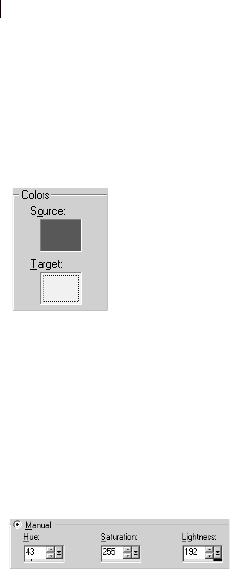
Chapter 5: Improving Photographs
102
4 Choose the Target color using one of these methods:
To choose from a preset color category, select the Preset
colors option, choose a color category from the list, and then
choose a color from within the category. See “Choosing Color
Categories” on page 102.
To choose from the Color dialog, left-click the Target color
box. See “Choosing Colors” on page 239.
To choose from recently used colors, right-click the Target
color box.
To choose from any open image, move the cursor over the
image until it changes into a dropper and then click the color.
To choose a color based on its hue, saturation, and lightness
(HSL) values, select the Manual option, and then enter the
values.
When you select the color, the Target color box displays the
target color.
5 If you are using the Preset colors option or have selected a
source color from the Target color box, choose from the
following options:
Preserve Lightness Mark this check box to preserve the lightness
of the source color in the corrected image. Clear this check box
to match the lightness of the corrected image to the target color’s
lightness.
Preserve Saturation Mark this check box to preserve the
saturation of the source color in the corrected image. Clear this
check box to match the saturation of the corrected image to the
target color’s saturation.
6 Click OK.
Choosing Color Categories
The preset color categories of the Manual Color Correction dialog
consist of a variety of frequently occurring colors. Most of these
categories are called memory colors because people remember them
particularly well and notice when they don’t look natural. Typical
examples are skin tones and sky colors. Memory color categories in
the Color Category list are Beverage, Foliage, Fruits, Grasses,
Grays, Hair Colors, Metals, Skintones, Sky, Various Foods,
Vegetables, Water, and Woods.
The Source and Target color
boxes
Select target colors manually by
entering Hue, Saturation, and
Lightness values
Preserving lightness and
saturation
If you mark Preserve Lightness and
Preserve Saturation, and the
source and target colors are similar
hues, you may not notice much
change in the adjusted image. Try
clearing one or both options.
To match the target color exactly,
clear Preserve Lightness and
Preserve Saturation.

Chapter 5: Improving Photographs 103
There are other categories that you may find helpful when defining
the target colors for your photographs:
Pure Colors The main colors on the color wheel (example, red,
orange, yellow).
Standard A set of colors designed to let you make very subtle
changes in hue. When you select a source color, the Nearest preset
color field above the list displays a number for the color that is the
closest match in the Standard category.
To correct an image using Standard Colors:
1 Choose Adjust > Color Balance > Manual Color Correction.
2 Click in the left preview window to select a source color.
3 Select the Preset colors option.
4 In the list underneath, choose Standard.
The Nearest preset color area above the list box displays the
Standard color that is the closest match to the source color. Click
the Color box to the right of the list and scroll to view the color.
5 Modify the target color using one of the following options:
To shift all hues in the image slightly, choose a color from the
Preset colors list that is similar to the current color.
To shift all hues in the image drastically, choose a color from
the Preset colors list that is quite different from the current
color.
Preserve Lightness Mark this check box to preserve the
lightness of the source color in the corrected image. Clear this
check box to match the lightness of the corrected image to the
target color’s lightness.
Preserve Saturation Mark this check box to preserve the
saturation of the source color in the corrected image. Clear
this check box to match the saturation of the corrected image
to the target color’s saturation.

Chapter 5: Improving Photographs
104
Using Grey World to Adjust Colors
Like the Automatic Color Balance command, the Grey World Color
Balance command corrects image colors, but it uses a different
mathematical algorithm.
The premise behind this command is that the average of all colors in
the image should be neutral. Although this may be a reasonable
approximation for some complex images, it isn't true for all images.
(For example, an image dominated by a blue sky.) You should
therefore use your own judgement to determine if this command is
appropriate for your image.
By default the Grey World Color Balance command balances in way
that causes neutral objects to have approximately equal red, green,
and blue components. When viewed on a typical computer monitor,
this corresponds to a color temperature of about 6500k. The Grey
World command allows you to simulate other color temperatures
relative to 6500k by adjusting the Illuminant Temperature control to
higher values (to produce cooler neutrals with larger blue
components and reduced red and green components) or lower values
(to produce warmer neutrals with smaller blue components and
increased red and green components).
To correct colors using the Grey World dialog:
1 Choose Adjust > Color Balance > Grey World Color Balance.
The right preview window shows the image colors automatically
corrected with the Grey World algorithm.
2 In the preview window, center an important part of the image
(such as a face). Pan the image by clicking and dragging in the
preview window; zoom in or out as necessary.
3 In the Illuminant Temperature group box, type a value or drag the
slider to change the image’s illuminant temperature from warmer
tones (oranges) to cooler tones (blues). The default setting is
6500K, which gives the effect of a photo taken in typical
daylight. Photos taken indoors tend to look more orange, while
photos taken in bright sunlight tend to look more blue. Adjust the
value to achieve the desired effect or until the colors look the
most natural.
4 Click OK.
When not to use Grey World
color correction
This color correction may not work
well for:
Very simple scenes with few
colors
Images with a limited range of
hues (such as mostly blues)
Simple computer-generated
graphics

Chapter 5: Improving Photographs 105
Correcting Faded Images
With time and exposure to the elements, especially light, the dyes in
a photograph fade. Colors become less vivid, the image acquires an
undesirable color cast, and contrast is lost. Use the Fade Correction
command to restore color and contrast to faded photographic
images. You can apply the command to a selection or an entire
image.
The Fade Correction command is a simple, one-step adjustment that
corrects both color and contrast. If the resulting image doesn’t look
as good as you would like, the image may need different
adjustments. Instead, try applying the three automatic adjustments
from the submenus of the Adjust menu in this order: Automatic
Color Balance, Automatic Contrast Enhancement, Automatic
Saturation Enhancement.
To use fade correction:
1 Choose Adjust > Color Balance > Fade Correction.
2 In the preview window, center an important part of the image
(such as a face). Pan the image by clicking and dragging in the
preview window; zoom in or out as necessary.
3 For Amount of correction, start with 45 and adjust the value until
the image looks the most natural.
Note: Use the minimum value that produces a good correction. If
you apply too much correction, highlight and shadow areas may
lose detail and objects may blend together.
4 Click OK.
Color depth
The Fade Correction command
works on 16 million color images
only. To increase the color depth of
an image, see “Increasing the Color
Depth of an Image” on page 261.
Have a faded black-and-
white photo?
Black-and-white photos have no
colors to correct. Instead, use the
Automatic Contrast Enhancement
command to restore the
photograph. See “Automatically
Enhancing Contrast” on page 106.

Chapter 5: Improving Photographs
106
Improving Contrast
The tone scale (contrast) of an image represents the distribution of
lightness values. It is a combination of Brightness and Contrast.
The brightness of an image relates to the overall sensation you get
when it is viewed. If most of the tones are large, the image appears to
be bright. If most of the tones are small, the image appears to be
dark. Adjusting the brightness therefore tends to shift the average
tone value either up (to make the image brighter) or down (to make it
darker).
The contrast of an image relates to the range that the tones occupy. If
most of the tones in an image are similar to each other, then the
image has a low contrast and appears "flat." If the tones are spread
widely across the scale, then its contrast is high. Therefore a contrast
adjustment either spreads the tones out (increasing the contrast) or
compresses them together (lowering the contrast).
Paint Shop Pro has several commands that are useful for adjusting
the brightness and contrast of an image. Go to the Adjust >
Brightness and Contrast submenu for a list of available commands.
Note: The Automatic Contrast Enhancement command works on 16
million color and greyscale images only. To increase the color depth
of an image, see “Increasing the Color Depth of an Image” on
page 261.
Automatically Enhancing Contrast
The Automatic Contrast Enhancement command is useful for
improving the tone distribution of your image. It automatically
adapts its behavior to the tone content of each image. Therefore, it
will be most effective when used without any selections, because
then the entire range of tones will be available for analysis.
Note: If you apply this command to a selection on an image, the
contrast adjustment may not be as effective because all the image
information is not available.
To automatically adjust contrast:
1 Choose Adjust > Automatic Contrast Enhancement.
2 In the preview window; center an important part of the image.
Pan the image by clicking and dragging in the preview window;
zoom in or out as necessary.

Chapter 5: Improving Photographs 107
3 Adjust the Bias (the brightness) of the correction: Lighter,
Neutral, or Darker.
4 Adjust the Strength of correction: Normal or Mild.
5 Adjust the Appearance of the correction:
Flat (a slight difference between light and dark areas)
Natural (an average difference between light and dark areas)
Bold (a striking difference between light and dark areas).
6 Click OK.
Improving Image Clarity
Improving image clarity is the final step in image correction. Use the
Clarify and Sharpen commands to clarify and sharpen your images.
Note
The Clarify and Sharpen Edge commands work on 16 million color
or greyscale images only. To increase the color depth of an image,
see “Increasing the Color Depth of an Image” on page 261.
Clarifying Images
Use the Clarify command to give your image a crisp, focused look so
objects stand out. This command adds a sense of depth and clarity to
the image. It can also make hazy, foggy, or slightly out of focus
images look clearer.
To clarify images:
1 Make sure the image has no selections. If necessary, choose
Selections > Select None. The Clarify command is not available if
the image contains a selection.
2 Choose Adjust > Brightness/Contrast > Clarify.
3 In the preview window, center an important part of the image
(such as a face). Pan the image by clicking and dragging in the
preview window; zoom in or out as necessary.
4 For Strength of effect, use the smallest value that gives a
satisfying result.
5 Click OK.
Accentuating Edges and
Contrast Areas
Use Edge effects to accentuate
edges and contrast areas in your
image. For more information on
Edge effects, see “Applying Edge
Effects” on page 222.

Chapter 5: Improving Photographs
108
Sharpening Images
Paint Shop Pro contains several commands that sharpen your image
by increasing the contrast of adjacent pixels:
Sharpen and Sharpen More Focus the image and improve its clarity
by increasing the contrast between adjacent pixels where there are
significant color contrasts, usually at the edges of objects. The
Sharpen More command sharpens with a stronger effect than the
Sharpen command. Both commands are automatically applied to the
image.
Unsharp Mask Sharpens the mid- to high-contrast edges in the image
without enhancing noise. This command locates adjacent pixels that
have a difference in lightness values that you specify and increases
their contrast by an amount you specify. This command is typically
used in professional color corrections.
To use the Sharpen or Sharpen More command:
Choose Adjust > Sharpness > Sharpen or Adjust > Sharpness >
Sharpen More.
To use the Unsharp Mask dialog:
1 Choose Adjust > Sharpness > Unsharp Mask.
2 In the preview window, center an important part of the image
(such as a face). Pan the image by clicking and dragging in the
preview window; zoom in or out as necessary.
3 Sharpen the image with the following options:
Radius The number of pixels to adjust around each edge. A value
between 0.5 and 2 works best, depending on the image. A lower
value sharpens only the edge pixels, while a higher value
sharpens a wider band of pixels. The effect is much less
noticeable in print than on-screen because a small radius (for
example, 1 pixel) represents a smaller area in a high-resolution
printed image. Therefore, use lower values for on-screen images
and higher values for high resolution printed images.
Strength The amount of contrast to increase in the image’s
pixels. Start with a low value and increase it gradually.
Clipping The difference in lightness values that adjacent pixels
must have before they are sharpened.
4 Click OK.

Chapter 5: Improving Photographs 109
Improving Saturation
After you have adjusted the tones of your image (by using the
Automatic Contrast Enhancement command), adjust the saturation.
Saturation is an indicator of the relative amount of color vividness.
Imagine a highly saturated color like bright orange. As the saturation
is reduced (keeping the hue and lightness unchanged), the orange
color becomes brownish, then taupe and finally a middle neutral
grey (after the saturation has been set all the way down to zero).
Reducing the saturation "drains" the color away, leaving just the
greyscale component. Taupe and mauve are familiar, fairly low
saturation colors because they are quite neutral, with just a touch of
color. Apple red and banana yellow are high saturation colors.
Generally speaking, saturation is a measure of how different a color
is from a neutral grey of the same brightness.
For digital images, increasing the saturation can give the image
brilliant color and "punch." But too much saturation will distort
colors such as skin tones.
Paint Shop Pro has several commands that are useful for adjusting
the saturation of an image. Go to the Adjust > Hue and Saturation
submenu for a list of available commands.
Automatically Enhancing Saturation
The Automatic Saturation Enhancement command is useful for
improving the saturation of your image. It automatically adapts its
behavior to the color content of each image. Therefore, it will be
most effective when used without any selections, because then the
entire range of colors will be available for analysis.
Note
This command works on 16 million color and greyscale images
only. To increase the color depth of an image, see “Increasing the
Color Depth of an Image” on page 261.
If you apply this command to a selection (rather than the entire
image), the saturation adjustment may not be as effective because
all image information is not available.
This command has no effect on greyscale images because they
have no color, it can be used on sepia or duotone images.
To automatically enhance saturation:
1 Choose Adjust > Automatic Saturation Enhancement.

Chapter 5: Improving Photographs
110
2 In the preview window, center an important part of the image
(such as a face). Pan the image by clicking and dragging in the
preview window; zoom in or out as necessary.
3 Set the Bias (which is the overall saturation) to your preferred
target saturation. The command will automatically adjust the
saturation to match this target.
4 Set the Strength of the correction to Weak, Normal or Strong.
5 Mark the Skintones present check box if appropriate. With this
enabled, the saturation adjustment algorithm is modified in a way
that produces more natural looking skin tones.
6 Click OK to apply the correction.
Removing Image Defects and Noise
Sometimes images have defects that are called noise—black, white,
or colored specks ranging in size from very tiny to relatively large or
all-over noise that gives surfaces a grainy look. You can use Paint
Shop Pro’s Noise commands to remove noise from images. Before
you decide which command to use, determine the type of noise that
your image contains.
Note
All Noise commands work on 16 million color and greyscale images
only. To increase the color depth of an image, see “Increasing the
Color Depth of an Image” on page 261.
Removing Single-Pixel Specks
Use the Despeckle command to remove single-pixel specks that are
mostly white or black. This command analyzes the brightness of
each pixel and compares it to the surrounding pixels to determine if
it should be removed.
To remove single-pixel specks in an image:
1 Select the area that contains the specks.
2 Choose Adjust > Add/Remove Noise > Despeckle. The selection
is despeckled.

Chapter 5: Improving Photographs 111
Removing Multiple-Pixel Black or
White Specks
Use the Salt and Pepper Filter command to remove multiple-pixel
black or white specks, such as those caused by dust on film or video.
This command compares an area of pixels to the surrounding pixels
and adjusts an area that is a speck to match those surrounding pixels.
To remove multiple-pixel specks:
1 Select the area that contains the specks. See “Using the Selection
Tools” on page 192.
2 Choose Adjust > Add/Remove Noise > Salt And Pepper Filter.
3 Define the adjustment using the following options:
Speck size The minimum size, in pixels, of the largest speck that
can be completely removed. The value is always an odd number.
Sensitivity to specks How different an area must be from its
surrounding pixels to be considered a speck.
4 Mark the Include all lower speck sizes check box to have Paint
Shop Pro remove all lower speck sizes. Results are usually better
if you mark this check box.
5 Mark or clear the Aggressive action check box to set whether the
strength of correction is normal (if the check box is cleared) or
aggressive (if the check box is marked).
6 Click OK.
Removing Noise While Preserving
Edge Details
Use the Edge Preserving Smooth command to remove noise in an
image without losing edge details. This command finds details such
as object edges and preserves them, while smoothing the areas
between the edges. For example, you can preserve the edges of facial
features while removing a blotchy complexion.
You can also use the Edge Preserving Smooth command to minimize
film grain.
To remove noise while preserving edge details:
1 Select the area that contains the noise.
Should I make a
selection first?
You can apply the Edge Preserving
Smooth command to a selection or
an image. It is faster and more
effective when applied to a
selection.

Chapter 5: Improving Photographs
112
2 Choose Adjust > Add/Remove Noise > Edge Preserving Smooth.
3 For Amount of smoothing, change the value until you are
satisfied with the adjustment. Choose the smallest amount of
smoothing that removes the specks while retaining image detail.
4 Click OK.
Removing Small Areas of Noise
Use the Median Filter command to remove small random specks or
areas of noise that are distinctly different from the surrounding area.
You can also use the command to remove single-pixel colored
specks.
The Median Filter command adjusts the intensity of each pixel in the
image to the median intensity of surrounding pixels. The median
intensity is the middle value (not the average) in the range of values.
To preserve object edges, the Median Filter command adjusts a pixel
that is very different from surrounding pixels more than a pixel that
is similar to surrounding pixels. You can choose the number of
surrounding pixels to use in the calculation. If you choose a large
number, more noise is removed and so more detail is lost.
To remove small areas of noise:
1 Select the area that contains the noise.
2 Choose Adjust > Add/Remove Noise > Median Filter.
3 For Filter Aperture, choose the number of surrounding pixels to
include in determining the median intensity of each pixel. The
filter is always an odd number of pixels. To preserve image
details, choose the smallest filter that removes the noise.
For single-pixel colored specks, set the filter to 3.
4 Click OK.

Chapter 5: Improving Photographs 113
Removing Noise While Keeping Texture
Details
Use the Texture Preserving Smooth command to remove noise or
specks in an image while preserving texture details. This command
analyze’s an image’s pixels to determine if they display textured or
smooth areas. Textured areas are preserved (few noise adjustments
are made) and smooth areas are adjusted to remove noise. For
example, textures in clothing may be preserved while noise from
another area (such as a person’s face) is removed.
To remove noise while keeping texture details:
1 Select the area that contains the noise.
2 Choose Adjust > Add/ Remove Noise > Texture Preserving
Smooth.
3 For Amount of correction, set a value to choose the strength of
the correction. At lower values, a small amount of noise is
removed but textured areas are preserved. At higher values, more
noise is removed but textured areas may not be fully preserved.
4 Click OK.
Softening the Image
The three Softness commands are Soft Focus, Soften, Soften More.
Soften applies a uniform blur to your image. Soften More applies the
Soften command with more intensity. The Soft Focus command
makes the image look as though it was taken with a camera using a
soft focus filter.
To use the Soften and Soften More commands, choose Adjust >
Softness and either the Soften or Soften More command.
To use the Soft Focus command:
1 Choose Adjust > Softness > Soft Focus to open the dialog.
2 In the preview window, center the important part of the image.
Pan the image by clicking and dragging in the preview window;
zoom in or out as necessary.
3 For Softness, set a percentage value to choose the strength of the
correction. At lower values, the image is softened only a small
amount. At higher values, the image appears to have a blurred
effect.
Should I make a
selection first?
You can apply the Texture
Preserving Smooth command to a
selection or an image. The
command is faster and more
effective when applied to a
selection.

Chapter 5: Improving Photographs
114
4 For Edge importance, set a percentage value to choose the
strength of the correction. At lower values, the edges of the
image are softened. At higher values, the detail of the edges are
retained.
5 Mark the Include scattered light check box if you want bright
areas in the background of the image to be softened.
6 For Amount, set a percentage value to choose the strength of the
halo effect. At lower values, the halo is added to only very bright
areas in the image. At higher values, a halo effect is created
around bright areas.
7 For Halo size, set a percentage value to choose the size of the
halo. At lower values, the halo is small. At higher values, the
halo effect is large.
8 For Halo visibility, set a percentage value to choose the strength
of the halo visibility. At lower values, the halo effect is subtle. At
higher values, the halo effect is more obvious.
9 Click OK.
Removing Source Defects
Images can contain defects that come from the process of scanning
or capturing them
Note
These commands work on 16 million color and greyscale images
only. To increase the color depth of an image, see “Increasing the
Color Depth of an Image” on page 261.
Fixing Line Problems in Video Images
Video images can contain visible scan lines. In these images, lines
can be missing or out of alignment with other lines. The resulting
image looks excessively blurry.
Use the Deinterlace command to eliminate missing or misaligned
lines from your image and to reconstruct missing information. If the
image contains noise, it may become more visible after removing
scan lines. For information on removing noise, see “Removing
Image Defects and Noise” on page 110.
Note: Apply the Deinterlace command before you resize the
image. Resizing adds or removes pixels from the image, which
makes it more difficult to determine scan lines.

Chapter 5: Improving Photographs 115
If your image has already been resized, you must return it to as close
to the original size as possible so that each scan line is one pixel
high. Zoom in until you can see individual pixels to determine how
many pixels make up one scan line, and then resize the image so that
each scan line is one pixel. For example, if the enlarged image has
scan lines that are two pixels high, you would resize it by 50 percent.
Keep in mind that the image loses clarity when you resize it.
To deinterlace an image:
1 Make sure the image has no selections. If necessary, choose
Selections > Select None. The Deinterlace command is not
available if the image contains a selection.
2 Choose Adjust > Add/Remove Noise > Deinterlace.
3 In the preview window, center the area of the image where the
scan lines are most apparent.
4 For Scanlines to retain, select either Odd or Even to determine
whether the odd-numbered or even-numbered scan lines are kept.
5 Click OK.
Removing Artifacts from JPEG Images
When you save a file to the JPEG format from any software package
(such as scanning software), the file information is compressed to
create a smaller file. The compression produces artifacts—unwanted
image problems—that can appear as halos or color leakage beyond
the edges of objects, checkerboard problems on smooth
backgrounds, or blocky-looking areas in an image.
Use Paint Shop Pro’s JPEG Artifact Removal command to restore a
JPEG image to its original appearance.
Note
Because JPEG compression discards image information, there are
limits to how well the image can be restored.
To remove JPEG artifacts:
1 Make sure the image has no selections. If necessary, choose
Selections > Select None. The JPEG Artifact Removal command
is not available if the image contains a selection.
2 Choose Adjust > Add/Remove Noise > JPEG Artifact Removal.
3 In the preview window, center the area of the image where the
artifacts are most apparent.
What if my file is not in
JPEG format?
You can apply the JPEG Artifact
Removal command to a file in any
format. For example, if you have
saved a JPEG file as a Paint Shop
Pro (.PspImage) file, you can still
apply the command.

Chapter 5: Improving Photographs
116
4 In the Strength group box, set the strength of correction to Low,
Normal, High, or Maximum. For best results, try each option and
examine all areas of the image to see which strength setting
works best.
5 Set the Crispness to determine the amount of detail that is
restored, from 0 (the least) to 100 (the most). Start with 50 and
adjust the value until the image looks the most natural. This
option determines how much fine-detail information the artifact
removal attempts to create. The recreated information can only
be a guess since the original information is lost. Excessive
crispness may produce fine dots in the image.
6 Click OK.
Removing Undesirable Patterns in
Scanned Images
Scanning printed images can produce undesirable patterns called
Moiré patterns. Other patterns may come from scanning photographs
printed on textured paper. Paint Shop Pro’s Moiré Pattern Removal
command removes these patterns from your images. You can apply
the command to a selection or an entire layer.
To remove moiré patterns:
1 Choose Adjust > Add/Remove Noise > Moiré Pattern Removal.
2 Magnify the image in the preview window until you can see the
fine patterns clearly.
3 For Fine details, select a value to remove fine patterns. Change
the value one number at a time until the pattern just disappears.
Higher values may blur the image, so use the lowest value that
removes the pattern.
4 Reduce the image magnification until you can see bands or color
blotches clearly in the preview window. Bands or blotches may
be visible when the image is at 100%, but may be easier to see at
smaller percentages.
5 For Remove bands, change the value one number at a time until
any color bands or blotches are less visible (they may not
disappear completely). Use the lowest value possible to avoid
desaturation of small objects.
6 Click OK.

Chapter 5: Improving Photographs 117
Note
After you have removed the Moiré pattern, you may be able to use
the Sharpen commands to restore detail and remove blurriness
without reintroducing the pattern. This approach works best when
you choose a Fine Details setting in the Moiré Pattern Removal
dialog that is slightly higher than needed to remove the pattern. For
more information on the Sharpen commands, see “Clarifying
Images” on page 107.
Retouching Photographs
Paint Shop Pro offers many options for retouching your photos. You
can remove red eyes from people, or the green eyes of animals using
the Red Eye Removal command. If there are scratches, cracks, and
other unwanted defects on a relatively smooth background, use the
Scratch Remover tool. If there are many small scratches or creases,
use the Automatic Small Scratch Remover command. If there are
elements you want to remove, use the Clone Brush tool. Use the
retouch tools to lighten, darken, emboss, change colors, and apply
other retouches to parts of the image.
Note
The Red Eye and Small Scratch Removal commands work on 16
million color images only. To increase the color depth of an image,
see “Increasing the Color Depth of an Image” on page 261
Removing Red Eyes
When you take a flash picture of people, sometimes their eyes look
red—the result of the flash’s light reflecting off the retina of the eye.
Use the Red-Eye Removal command to return eyes to natural colors.
You can also use this command to enhance or change eye colors.
To use the Red Eye Removal command:
1 Make sure the image has no selections. If necessary, choose
Selections > Select None. The Red-Eye Removal command is not
available if the image contains a selection.
2 Choose Adjust > Red Eye Removal.
3 In the right preview window, center the red eyes of the subject.
Pan the image by clicking and dragging in the preview window;
zoom in or out as necessary.

Chapter 5: Improving Photographs
118
Note: You must use the right preview window for panning the
image because you select the subject’s eyes in the left preview
window.
4 From the Method drop-down list, select a correction method:
Auto Human Eye Automatically selects the correction area using
a circular selection and chooses settings appropriate to a human
eye. If you are correcting human eyes (even partially obscured
ones), try this method first.
Auto Animal Eye Automatically selects the correction area using
a circular or elliptical selection area and chooses settings
appropriate to an animal eye. You can also rotate the selection
with this method. If you are correcting animal eyes, try this
method first.
Freehand Pupil Outline Manually select the correction area on
human or animal eyes using a Freehand Selection tool. Use this
method for difficult situations, such as a partially obscured pupil.
Point-to-Point Pupil Outline Manually select the correction area
on human or animal eyes using a Point-to-Point Selection tool.
Use this method for difficult situations, such as a partially
obscured pupil.
5 In the left preview window, select the first eye to correct:
For the Auto Human Eye or Auto Animal Eye method, click
anywhere inside the red area of the eye to select the eye
automatically. You can also click and drag from the center of
the eye to the outside edge of the red area.
For the Freehand Pupil Outline method, click and drag the
cursor around the edge of the red area of the pupil. Release the
mouse button when you reach the beginning point of the
selection.
For the Point-to-Point Pupil Outline method, left-click at
points a few pixels apart around the edge of the red area of the
pupil. (Right-click to reverse a click.) When you reach the
beginning point, double-click.
Note: To remove a selection, click Delete.
After you select the eye, a circle appears around the selected area
and a control box for making adjustments encloses the circle. The
right preview window displays the corrected eye.
So you always wanted
blue eyes...
To use the Red-Eye Removal
command to enhance or change
eye colors, follow the same steps
for correcting red eyes with these
special instructions:
Select the new eye color.
Select the entire eye (pupil and
iris).
Adjust the Iris Size setting until
the pupil and iris look natural.
Use the Feather and Blur
settings to make the new eyes
look more natural.
About manual eye
correction methods
For both the Pupil Outline methods,
select the pupil (the small dark
circle at the eye’s center), not the
entire eye. These methods correct
red pupils on humans and animals,
but do not correct human irises
(you’ll notice the Hue option for
setting the iris hue is not available).
Typically, red-eye effect is confined
to the pupil, so with these manual
methods you can correct the red
pupil.

Chapter 5: Improving Photographs 119
6 Make sure the selection is positioned and sized properly over the
red area of the eye:
To move the selection, drag it to a new location.
For the Auto Animal Eye method, drag the center rotation
handle to rotate the selection. You can also reshape the eye
from a circle to an ellipse by dragging its side handles.
7 Fine-tune the eye correction by adjusting the pupil size and
lightness, glint, iris size, and feathering and blurring of the iris.
Refer to the fine-tuning steps later in this section.
8 To correct other red eyes, repeat the previous steps. The settings
from the first eye are retained, so the subsequent corrections
should be much quicker.
9 Click OK.
To fine-tune the eye correction on the Red-Eye Removal dialog:
1 For a human eye, look at the corrected eye to see if you need to
adjust the iris area around the pupil. (An animal eye usually does
not show an iris.) Sometimes the red eye area covers the iris. If
needed, adjust the iris with the following options:
Iris Size The size of the iris. Increasing the iris size decreases the
pupil size.
Hue The color of the iris (such as blue, brown, or green). This
option is not available for the Freehand Pupil Outline and Point-
to-Point Pupil Outline methods because these methods select the
pupil, rather than the pupil and iris.
Color The color variation of the iris (such as light blue or deep
blue).
2 For Pupil lightness, adjust the value so that the corrected eye
appears the appropriate shade and matches your perception of the
natural color.
3 Examine the glint in the eye. A glint makes the eye look natural
and lively; without it the eye looks “dead.” Adjust the glint using
the following options:
Glint size The size of the glint.
Glint lightness The lightness of the glint. Lower values darken
the glint; higher values lighten it.
Center glint Mark the check box to move the glint to the center of
the pupil. Clear it to leave the glint at its original position.
Need to change a setting?
To make further corrections on any
eye you have selected, click the
circle surrounding the eye. You can
change any of the settings except
Method. To change the correction
method, remove the selection (click
Delete), select the method, and
then select the eye again.

Chapter 5: Improving Photographs
120
4 Use Refine when the eye is partially obscured in the original
image. For example, if the eyelid covers part of the original eye,
it should cover it in the corrected eye. Use the Refine Slider to
reduce the correction. Slowly drag the slider to the left to reduce
the correction and minimize its overlap with the surrounding
skin.
5 To blend the corrected eye with the rest of the image, set the
following options:
Feather Adjusts the edges of the corrected eye. Smaller values
make the edges more defined; larger values blend the edges to
the surrounding image areas.
Blur Blends the eye with surrounding pixels when the photo has a
grainy appearance. Increase the setting one unit at a time until the
eye blends naturally with the rest of the image.
Removing Scratches with the Scratch
Remover Tool
The Scratch Remover tool is one way to remove scratches, cracks,
and other defects from your images. Use the tool to enclose the area
with the scratch and erase it. The tool works best for scratches on
relatively smooth backgrounds.
Note
This tool can be used only on backgrounds; it is not available when
you are working on layers.
If there are many small scratches in the image, use the Automatic
Small Scratch Remover command. See “Removing Scratches with
the Automatic Small Scratch Removal Command” on page 122.
To use the Scratch Remover tool:
1 If necessary, click the background layer on the Layers palette.
2 To limit the correction to a specific area, make a selection. (See
“Using the Selection Tools” on page 192.) This step works well
when you need to be careful not to remove important details near
the scratch.
3 Select the Scratch Remover tool .
Correcting obscured human
eyes
If a human eye is partially
obscured, select the Auto Human
Eye method, and then use the
Refine setting to adjust the
correction area.
Smooth vs. textured
background
The Scratch Remover tool uses the
background image details to create
new information to replace the
scratch. If the background is
relatively smooth, the result is
usually satisfying.
To remove scratches from a
textured background, the Clone tool
may be more effective. See
“Cloning Parts of Images” on
page 290.
Chapter 5: Improving Photographs 121
4 On the Tool Options palette, set the following options:
Width The width, in pixels, of the tool. Choose a width that is
about 3 or 4 pixels wider than the scratch. If the width is
considerably larger than the scratch, you will lose image detail.
Selection boxes The shape of the Scratch Remover tool. Select
the flat-end option to correct scratches that are perpendicular
to object edges in the image or are in an open area (the
background is similar and has no objects in it). Select the
pointed-end option to correct scratches at an angle to object
edges in the image (with this option, you can place the tool closer
to the edges).
5 Center the cursor just outside one end of the scratch, then click
and drag the bounding box over the scratch:
If the tool width is 10 or fewer pixels, the box is single-sided.
Position the box so that the edges surround, but do not touch,
the scratch.
If the tool width is more than 10 pixels, the box is double-
sided. Position the box so that the inner edges surround, but
do not touch, the scratch.
6 With the mouse button still pressed, you can adjust the size and
position of the rectangle:
Press the Arrow keys to move the starting point of the
bounding box by 1 pixel.
Press PageUp or PageDown to increase or decrease the width
of the box by 1 pixel.
7 When the rectangle properly encloses the scratch, release the
mouse button. The scratch is removed.
If you are not satisfied with the result, click Undo to undo the
scratch removal, then try selecting the scratch again (perhaps
varying the width of the tool).
Achieving the best results
If the scratch background is highly
textured or contains many image
variations (say, a flower, a face,
and a wall), the result may not be
as satisfying.
Try these tips to get the best
results:
Before using the tool, select the
area that contains the scratch.
Use a tool width about 3 or 4
pixels wider than the scratch
itself.
For scratches over several
different backgrounds, try
removing the scratch a section at
a time.
Consider using the Clone Tool
instead.

Chapter 5: Improving Photographs
122
Removing Scratches with the Automatic
Small Scratch Removal Command
The Automatic Small Scratch Remover command finds and
eliminates small, line-shaped defects that are either lighter or darker
than the surrounding area.
To use the Automatic Small Scratch Removal command:
1 To limit the correction to a specific area, make a selection. (See
“Using the Selection Tools” on page 192.) The command works
best on a selection rather than the entire image.
2 Choose Adjust > Add/Remove Noise > Automatic Small Scratch
Removal.
3 Mark the check box of the type of scratches to remove (you must
choose at least one option):
Remove dark scratches Mark this check box to remove scratches
that are darker than their background.
Remove light scratches Mark this check box to remove scratches
that are lighter than their background.
4 Specify how scratches are removed with the options in these two
group boxes:
Local contrast limits The difference in contrast between a scratch
and its background. Use a value that sets the limits to where they
achieve the best results. Start with the Lower limit at 0 and the
Upper limit at 50. If scratches remain, the Automatic Small
Scratch Removal command is unable to remove them. If
scratches disappear, then adjust the limits to minimize loss of
image detail. Adjust the Lower limit up to the setting just below
where scratches reappear. Adjust the Upper limit down to the
setting just above where the scratches reappear.
Strength The strength of the scratch removal: Mild, Normal, or
Aggressive. Select the lowest setting that removes scratches.
Look at all areas of the image to make sure important details are
not lost.
5 Click OK.
Color depth
The Automatic Small Scratch
Removal command works on 16
million color or greyscale images
only. To increase the color depth of
an image, see page 261.
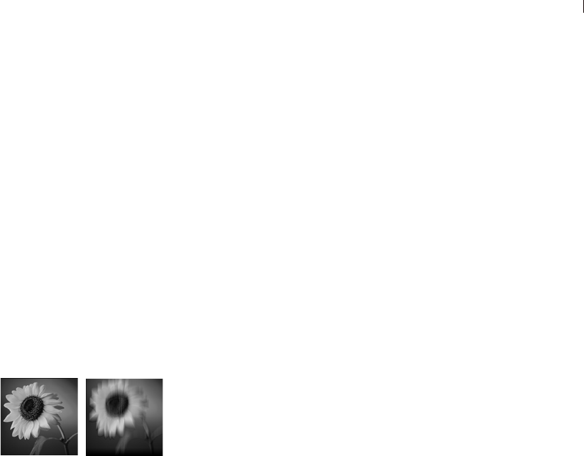
Chapter 5: Improving Photographs 123
Blurring Images
Use Blur to soften a selection or an image. Blur images for photo
retouching or to remove noise in the image. The Blur commands
smooth transitions and decrease contrast by averaging the pixels
near edges and areas of significant color transitions.
To increase the effect of any of the Blur effects, apply them multiple
times to the same image.
Note
These commands work on greyscale and 16 million color (24-bit)
images only. To increase the color depth of an image, see
page 261.
For descriptions and visual examples all the blur commands,
refer to the Help system.
Select from the following blur commands:
Average Removes noise that occurs throughout an image by
adjusting the intensity of each pixel to the average intensity of its
surrounding pixels. Also removes color dithering that results from
increasing the color depth of an image from paletted to 24 bit.
Blur and Blur More Remove noise by applying smooth transitions
and decreasing the contrast in your image. The Blur More effect
applies the Blur effect with more intensity. Use either effect to
reduce graininess in your image.
Gaussian Blurs an image by an adjustable amount. Blends a specific
number of pixels incrementally, following a bell-shaped curve. The
blurring is dense in the center and feathers at the edges.
Motion Blur Blurs in a particular direction (from 0 to 359 degrees)
and at a particular strength (from 1 to 100). Use this effect to
simulate taking a picture of a moving object using a fixed exposure
time.
Radial Blur Blurs an image by simulating what you might see if you
took a picture while spinning a camera in circles, or by zooming in
quickly using a very slow shutter speed. You can also choose a
twirling effect
To apply a Blur effect:
1 On the Layers palette, click the layer containing the area you want
to blur.
2 To limit the blur to a specific area, make a selection in the image.
Applying the Motion Blur effect

Chapter 5: Improving Photographs
124
3 Choose Adjust > Blur, then choose a effect.
For the Blur and Blur More effects, the effect is applied to the
image or selection.
For the Average, Gaussian, and Motion effects, a dialog
opens. Choose from the options, then click OK. The effect is
applied to the image or selection.
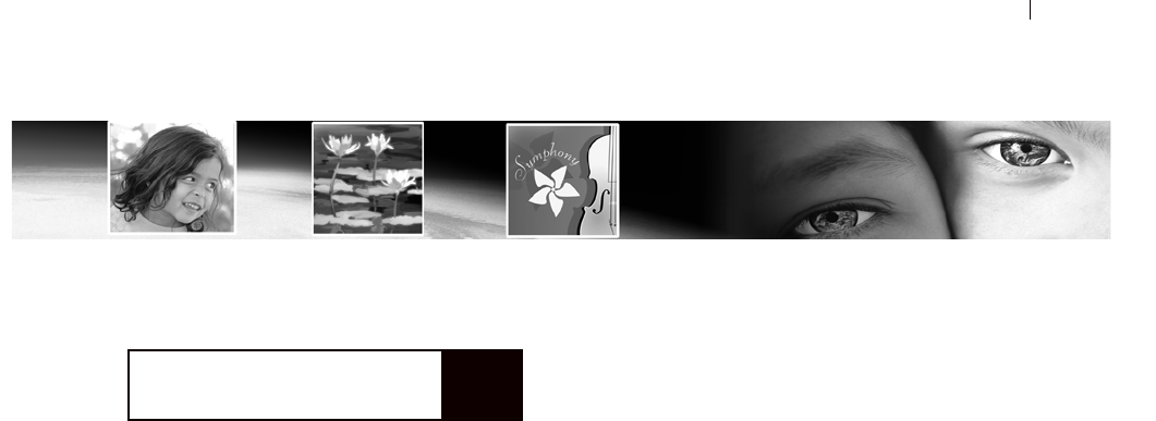
125
Making Color and Tonal Corrections
Paint Shop Pro provides advanced and flexible commands that aid in
color corrections and create dramatic effects.
Start your corrections with Paint Shop Pro’s automatic commands
and then use the advanced correction commands if your images still
need adjusting. For an introduction to color and tonal corrections,
see “How to Approach Color, Contrast, and Saturation Adjustments”
on page 96. For an overview of steps that help you improve your
photographs, see “Basic Steps in Improving Photographs” on
page 88.
Contents Key Points to Know Before Making Corrections. . . . . . . . . . . . . 126
How Corrections Relate to Color Depth. . . . . . . . . . . . . . . . . . . 127
Adjusting the Color Balance. . . . . . . . . . . . . . . . . . . . . . . . . . . 128
Adjusting Brightness and Contrast . . . . . . . . . . . . . . . . . . . . . . 134
Replacing Colors. . . . . . . . . . . . . . . . . . . . . . . . . . . . . . . . . . . 140
Reducing or Removing Colors . . . . . . . . . . . . . . . . . . . . . . . . . 142
Using the Histogram to Analyze Images . . . . . . . . . . . . . . . . . . 145
CHAPTER 6

Chapter 6: Making Color and Tonal Corrections
126
Key Points to Know Before Making Corrections
All the Paint Shop Pro correction command dialogs have common
ways of adjusting color and lightness. Keep the following key things
in mind:
Lightness levels are specified in a scale from zero (no light,
black) to 255 (100% light, white).
Image files store their color information in channels, or planes,
of color. A color channel specifies the amount of a certain color
in each pixel of the image. Many correction dialogs let you to
edit the red, green and blue channels. The histogram also
displays the hue, saturation, lightness, and greyscale channels.
Colors are specified on a scale from zero (no color) to 255 (100%
of the color).
Hue settings are displayed on a color wheel or they use values
that represent positions on the color wheel. For a visual
representation, look at the Jasc Color Picker. Although actual hue
values range from 0 to 255, some correction dialogs use degrees
to represent hues on the color wheel (from 0 to 359 degrees
counter-clockwise starting at the top).
When you first open a correction dialog, reset the settings by
choosing Default in the Presets drop-down list. Otherwise, the
dialog uses the settings from the previous correction.
If there’s an adjustment layer available for a correction
command, use it. That way the original pixels are left unchanged.
If you change your mind or want to revise the correction, it’s
much easier when you use an adjustment layer. See, “Using
Adjustment Layers” on page 382
Depending upon the color depth of your image, some correction
commands may not be available. It’s always best to work with
images of 16 million (24-bit) colors. If needed, you can reduce
the color depth when you finish editing the image. For more
information, see “How Corrections Relate to Color Depth” on
page 127.

Chapter 6: Making Color and Tonal Corrections 127
How Corrections Relate to Color Depth
The following table shows you which correction commands and
adjustment layers are available for images of different color depths
and which color depths can apply commands to selections.
Color
Depth Commands that Apply to
Entire Layer or Image Commands available
for Selections
Available
Adjustment
Layers
2 color (1-bit) Greyscale, Negative Image None None
16 color (4-bit) Greyscale, Posterize, Solarize, and
Sepia, plus all commands in the
Adjust menu
None None
256 color (8-bit) Same as 16 color (4-bit), plus the
Equalize and Stretch Histogram
commands
None None
Greyscale (8-bit) All commands that correct
brightness or contrast
The same commands
that work on the layer or
image
Brightness/Contrast,
Curves, Invert,
Levels, Posterize,
Threshold
16 million, 32K,
or 64K color
(24-bit)
All correction commands All correction commands All adjustment
layers

Chapter 6: Making Color and Tonal Corrections
128
Adjusting the Color Balance
In technical terms, color balance refers to the balance of red, green,
and blue in your images. In common usage, balancing colors means
creating natural looking images without a color cast (an overall
imbalance of colors in an image). Use Paint Shop Pro to correct
color balance and also to change the balance to create dramatic
effects.
Changing the Overall Color Balance
Use the Red/Green/Blue command to adjust the amount of red,
green, and blue in your image and to make color corrections by
changing the overall color cast. To reduce the amount of a color in
the image, you can either increase its opposite color on the color
wheel or reduce the amount of adjacent colors on the color wheel.
For example, to color correct an image containing too much yellow,
either increase the amount of blue or decrease the amount of red and
green.
To use the Red/Green/Blue command:
1 To limit the correction to a specific area, make a selection in the
image. See “Using the Selection Tools” on page 192.
2 Choose Adjust > Color Balance > Red/Green/Blue.
3 In the Red, Green, and Blue edit boxes, select the percentage to
change each value. A value of 0% indicates the original value. To
add more of a color, use a positive number. To remove some of a
color, use a negative number. Keep in mind the following:
Reducing the amount of blue adds a yellow cast to the image.
Reducing the amount of green adds a magenta cast to the
image.
Reducing the amount of red adds a cyan cast to the image.
4 Click OK.
Color depth
To apply this command to a
selection, the image must be a
16 million (24-bit) color image
(otherwise the command is applied
to the entire image).
To increase the color depth of an
image, see page 261.
The automatic alternative
For a quick and easy way to
balance colors, use the Automatic
Color Balance command. See
“Automatically Balancing Colors”
on page 100.

Chapter 6: Making Color and Tonal Corrections 129
Changing the Color Balance of
Shadows, Midtones, and Highlights
Use the Color Balance command to change the balance of colors in
an image. This command provides general color correction and
allows you to adjust the color balance in shadows, midtones, and
highlights.
To use the Color Balance command:
1 To limit the correction to a specific area, make a selection in the
image. See “Using the Selection Tools” on page 192.
2 Do one of the following:
To modify the image pixels directly, choose Adjust >
Color Balance > Color Balance.
To create an adjustment layer, choose Layers >
New Adjustment Layer > Color Balance. For information on
adjustment layers, see “Using Adjustment Layers” on
page 382.
3 To reset the settings, in the Presets drop-down list, select
Default.
4 In the Tone balance group box, select which lightness level
(tonal range) of colors to adjust: Shadows (dark colors),
Midtones (colors in the middle range), and Highlights (bright
colors). Adjust each one individually.
5 To have the corrected image match the lightness of the original
image, mark the Preserve luminosity check box.
6 In the Color balance group box, drag a slider toward a color to
increase that color in the image or drag a slider away from a
color to decrease the color. Increasing the proportion of one color
decreases the proportion of its opposite on the color wheel.
The values in the Color levels edit boxes show the color changes
for the red, green, and blue channels. Values range from -100 to
100. Zero indicates the original color balance.
7 Click OK.
Color depth
To apply this command to a
selection, the image must be a
16 million (24-bit) color image
(otherwise the command is applied
to the entire image).
In addition, adjustment layers are
available for 16 million (24-bit)
color images only.
To increase the color depth of an
image, see page 261.

Chapter 6: Making Color and Tonal Corrections
130
Adjusting the Hue, Saturation, and
Lightness in Unison
Use the Hue/Saturation/Lightness command to shift all colors in an
image and change their strength and lightness. Here’s how the
command works:
Changing the hue shifts all pixels in an image around the color
wheel to a different point. For example, if you change the red
pixels to green, the green pixels turn to blue and the yellow
pixels turn to cyan.
Changing the saturation adjusts the amount of grey in a color.
The level of grey increases as the saturation decreases.
Changing the lightness adjusts the color’s brightness.
To use the Hue/Saturation/Lightness command:
1 To limit the correction to a specific area, make a selection in the
image. See “Using the Selection Tools” on page 192.
2 Do one of the following:
To modify the image pixels directly, choose Adjust >Hue
and Saturation > Hue/Saturation/Lightness.
To create an adjustment layer, choose Layers > New
Adjustment Layer > Hue/Saturation/Lightness. For
information on adjustment layers, see “Using Adjustment
Layers” on page 382.
3 In the Edit drop-down list, choose the color range to adjust. To
edit all colors simultaneously, choose Master. To edit a specific
color range, choose Reds, Yellows, Greens, Cyans, Blues, or
Magentas.
The color rings represent the colors in the image. The outer ring
represents the original values and the inner ring represents the
adjusted values. If you choose a specific color range to edit, a
control ring is added between the inner and outer rings where you
can change the color range that you adjust.
4 To turn the image into a duotone (two-color) image, mark the
Colorize check box. The image turns into a greyscale image (if
you have previews or proofing on). You can now select a hue and
adjust the saturation and lightness values to colorize the image.
Color depth
To apply this command to a
selection, the image must be a
16 million (24-bit) color image
(otherwise the command is applied
to the entire image).
In addition, adjustment layers are
available for 16 million (24-bit)
color images only.
To increase the color depth of an
image, see page 261.
Creating a duotone
You can use the Hue/Saturation/
Lightness command or the Colorize
command to create a duotone
image (a greyscale image with one
color added).
For more information on duotones,
see “Colorizing Images” on
page 141.

Chapter 6: Making Color and Tonal Corrections 131
5 If you are editing a specific color range (rather than the Master
mode), you can change the color range that you adjust using the
control ring:
To set the range width, drag the two outer points on the
control ring, which mark the beginning and end of the
adjustment area.
To change where the adjustment builds to full effect, drag the
two inner bars. In the area between the two inner bars, the
adjustment is in full effect.
To move the adjustment area, drag the white circle.
6 To change the hue, drag the Hue slider until the colors appear as
you want them. You can also type a value in the Hue edit box.
The hue value is not on the typical hue scale of 0 to 255. Instead,
the value is the number of degrees of rotation around the 360
degree color wheel from the pixel’s original color. A positive
values indicates a clock-wise rotation and a negative value
indicates a counter-clockwise rotation. For example, when the
Hue value is at 180, blue becomes yellow and green becomes
magenta.
7 Drag the Saturation slider up to increase the saturation or drag it
down to decrease the saturation. Values can range from -100 to
100; at zero the saturation is unchanged.
8 Drag the Lightness slider up to increase the lightness or drag it
down to decrease the lightness. Values can range from -100 to
100; at zero the lightness is unchanged.
9 Click OK.

Chapter 6: Making Color and Tonal Corrections
132
Correcting Colors by Setting Black and
White Points
If an image has a color cast, an effective way to correct it is to select
those points that you know are supposed to be black or white and
shift all colors based on resetting these points to true black and true
white. You can do this with the Black and White Points command.
You can also define the grey point too. After you select the points,
all colors are shifted.
To use the Black and White Points command:
1 To limit the correction to a specific area, make a selection in the
image. See “Using the Selection Tools” on page 192.
2 Choose Adjust > Color Balance > Black and White Points.
3 In the right preview window, center the area with the source
points (the points that should be black, white, or grey). Pan the
image by clicking and dragging in the preview window; zoom in
or out as necessary.
Note: You must use the right preview window for panning the
image because you select the source colors in the left preview
window.
4 To use a greyscale palette to select all destination colors, mark
the Balance to grey check box. If this check box is cleared, you
can select any color for the destination points.
5 For each point that you want to correct, do the following:
Select the source point: click the color’s dropper button ,
then click a color in the left preview window that is supposed
to be the color you are correcting (black, grey, or white).
If you want, change the default color: for the Desired color
boxes, click the appropriate Color box (black, grey, or white)
and select a color from a black-and-white color palette.
Note: To select a destination color from the image window or
the desktop, position the cursor over any destination color
box, press and hold the Ctrl key, move the cursor over the
image or the desktop, and click a color.
6 To preserve the lightness of the source color, mark the Preserve
lightness check box. If this check box is cleared, the lightness of
the corrected image matches the target color’s lightness instead.
7 Click OK.
Color depth
To apply this command to a
selection, the image must be a
16 million (24-bit) color image
(otherwise the command is applied
to the entire image).
To increase the color depth of an
image, see page 261.

Chapter 6: Making Color and Tonal Corrections 133
Adjusting the Color Channels
Use the Channel Mixer command to increase or decrease the red,
blue, or green color channel by a percentage of itself and the other
two channels. Use this command when you want to adjust color
channels individually.
To use the Channel Mixer command:
1 To limit the correction to a specific area, make a selection in the
image. See “Using the Selection Tools” on page 192.
2 Do one of the following:
To modify the image pixels directly, choose Adjust > Color
Balance > Channel Mixer.
To create an adjustment layer, choose Layers >
New Adjustment Layer > Channel Mixer. For information on
adjustment layers, see “Using Adjustment Layers” on
page 382.
3 Do one of the following:
To maintain a color image, in the Output channel drop-down
list, select a color channel to edit: Red, Green, or Blue.
To change the image to a monochrome (which looks like a
greyscale but has a color depth of 16 million colors), mark the
Monochrome check box. The Channel drop-down list displays
Grey. When you adjust the color channels in the next step, you
change the amount of each channel that is used to create the
monochrome image.
4 In the Source channels group box, use the Red, Green, and Blue
edit boxes or sliders to change the current percentage of that
color in the channel you are editing. For example, if you are
editing the Red channel and set the Red value to 50%, you reduce
the amount of red in the image to 50% of its original amount.
5 To brighten the color channel, drag the Constant slider to the
right. To darken the color channel, drag the slider to the left. The
default of zero is the original setting.
6 Click OK.
Color depth
To apply this command to a
selection, the image must be a
16 million (24-bit) color image
(otherwise the command is applied
to the entire image).
In addition, adjustment layers are
available for 16 million (24-bit)
color images only.
To increase the color depth of an
image, see page 261.

Chapter 6: Making Color and Tonal Corrections
134
Adjusting Brightness and Contrast
There are numerous methods for correcting the brightness and
contrast of an image.
Analyze the image with the histogram and then use the histogram
commands to adjust the image.
Use the Brightness/Contrast command to adjust the brightness or
contrast individually.
Use the Curves command to change the brightness values of
individual pixels.
Use the Gamma Correction command to change the image’s
gamma, which adjusts the brightness and contrast in unison.
Adjust the brightness of highlights, midtones, and shadows to
improve contrast and bring out detail in light or dark areas.
Use the Levels command to adjust the lightness of the image.
Using the Histogram to Fix Contrast
Problems
In Paint Shop Pro there are three main ways to use the histogram to
fix contrast problems:
Use the Histogram Adjustment command to edit the luminosity
(or lightness) channel. See “Correcting Images by Adjusting the
Histogram” on page 148.
Use the Histogram Equalize command to average image
brightness by distributing the lightness values of pixels more
evenly across the lightness spectrum from black to white. This
command makes the darkest pixel as close to black as possible
and the lightest pixel as close to white as possible, and then
distributes the remaining pixels evenly between these two values.
Use the Histogram Stretch command to increase contrast. If an
image’s histogram does not cover the entire lightness spectrum,
the image does not contain very dark or very light areas and so it
lacks contrast. The Stretch command stretches the graph closer to
both ends so that it covers more of the spectrum. (You can also
do this manually with the Histogram Adjustment command.)
Automatic adjustment
Choose Adjust > Brightness and
Contrast > Automatic Contrast
Enhancement to adjust the
contrast with several easy-to-use
options.
Creative ideas for
equalizing
In some cases the effect of
equalizing the histogram of an
image may be too strong. You may
get better results when you blend
the original image with the
equalized version. Copy and paste
the original as a new layer, then
equalize the copied layer and use
the layer opacity options to blend
the two layers together.
For more information on the
opacity options, see “Changing
Opacity of Layers” on page 372.

Chapter 6: Making Color and Tonal Corrections 135
To use the Histogram Equalize command:
1 To limit the adjustment to a specific area, make a selection in the
image. See “Using the Selection Tools” on page 192.
2 Choose Adjust > Brightness and Contrast > Histogram Equalize.
The image updates in the image window.
To use the Histogram Stretch command:
1 To limit the adjustment to a specific area, make a selection in the
image.
2 Choose Adjust > Brightness and Contrast > Histogram Stretch.
The image updates in the image window.
Manually Adjusting Brightness and
Contrast
You can manually adjust the brightness and contrast of an image
using the Brightness/Contrast command. This is one of the simplest
of the lightness correction commands.
To adjust contrast and brightness manually:
1 To limit the adjustment to a specific area, make a selection in the
image. See “Using the Selection Tools” on page 192.
2 Do one of the following:
To modify the image pixels directly, choose Adjust >
Brightness and Contrast > Brightness/Contrast.
To create an adjustment layer, choose Layers >
New Adjustment Layer > Brightness/Contrast. For
information on adjustment layers, see “Using Adjustment
Layers” on page 382.
3 In the Brightness edit box, select a negative number to darken
the image or select a positive number to lighten image. A value
of zero indicates no change.
4 In the Contrast edit box, select a positive number to increase the
contrast or select a negative number to decrease the contrast. A
value of zero indicates no change.
5 Click OK.
Make your own adjustment
layer!
Although there are no adjustment
layers for the Histogram Equalize
and Histogram Stretch commands,
you can still apply the commands
without changing the original
image pixels. Make a copy of the
layer to which you are applying the
commands and paste it as a new
layer. Apply the commands to the
copied layer, and on the Layers
palette turn off the visibility of the
original layer.
You can use this trick with all Paint
Shop Pro correction commands
that don’t have an adjustment
layer.
Color depth
To apply this command to a
selection, the image must be a
16 million (24-bit) color image
(otherwise the command is applied
to the entire image).
In addition, adjustment layers are
available for 16 million (24-bit)
color or greyscale images only.
To increase the color depth of an
image, see page 261.
Using automatic corrections
To adjust the contrast with several
easy-to-use options (such as
choosing an appearance that is
flat, natural, or bold), use the
Automatic Contrast Enhancement
command. See “Automatically
Enhancing Contrast” on page 106.

Chapter 6: Making Color and Tonal Corrections
136
Adjusting Individual Brightness Values
Use the Curves command to adjust the individual brightness values
of your image. You can change any brightness value on the 0–255
scale. For example, you can change all pixels that have a brightness
value of 128 to a value of 150. The Curves command gives you
enormous flexibility in changing the brightness of your image.
To use the Curves command:
1 To limit the adjustment to a specific area, make a selection in the
image. See “Using the Selection Tools” on page 192.
2 Do one of the following:
To modify the image pixels directly, choose Adjust >
Brightness and Contrast > Curves.
To create an adjustment layer, choose Layers >
New Adjustment Layer > Curves. For information on
adjustment layers, see “Using Adjustment Layers” on
page 382.
3 To reset the settings, in the Presets drop-list choose Default.
4 In the Channel drop-down list, select a color channel to edit.
Choose RGB to edit the red, green, and blue channels together.
Choose Red, Green, or Blue to edit the individual color channels.
5 Use the points on the graph to adjust the relationship between the
input levels (the brightness of the original pixels) and output
levels (the brightness of corrected pixels). At the lower left of the
chart, both values are zero (black). At the upper right, both
values are 255 (white).
To add a point to the graph, move the cursor over the dotted
red line until the cursor changes to an arrowhead and displays
“+ADD,” then click the line.
To move the line, drag a point or enter values in the Input or
Output edit box.
To remove a point, drag it off the graph.
6 Click OK.
Color depth
To apply this command to a
selection, the image must be a
16 million (24-bit) color image
(otherwise the command is applied
to the entire image).
In addition, adjustment layers are
available for 16 million (24-bit)
color or greyscale images only.
To increase the color depth of an
image, see page 261.

Chapter 6: Making Color and Tonal Corrections 137
Adjusting the Brightness and Contrast
in Unison
Use the Gamma Correction command to adjust the brightness and
contrast of an image in unison. The gamma of an image is a standard
measure of its contrast and brightness.
The gamma curve has three components: the red, green, and blue of
the image. In addition to adjusting the brightness and contrast of the
image, with the Gamma Correction command you can adjust the
color balance of an image by unlinking the three components and
changing them separately. For example, if the image has a red cast to
it, you can reduce its red value.
To use the Gamma Correction command:
1 To limit the adjustment to a specific area, make a selection in the
image. See “Using the Selection Tools” on page 192.
2 Choose Adjust > Brightness and Contrast > Gamma Correction.
In the Gamma Correction dialog, the graph shows the gamma
curves for the three colors. If the three colors have the same
gamma value, there is one white line representing the three
colors. If the gammas are different values, there is a line for each
color.
The left side of the graph represents the shadows of the image;
the right side represents the highlights.
3 Do one of the following:
To adjust the brightness and contrast in unison, mark the Link
check box.
To change the color balance of the image rather than the
brightness and contrast, clear the Link check box.
4 For the Red, Green, and Blue values, drag the sliders or type new
numbers in the edit boxes. A value of 1 indicates the original
gamma. If colors are linked, increasing the value lightens the
image and decreasing the value darkens the image. If colors are
not linked, increasing or decreasing a individual color value
increases or decreases the amount of that color in the image.
Color depth
To apply this command to a
selection, the image must be a
16 million (24-bit) color image
(otherwise the command is applied
to the entire image).
To increase the color depth of an
image, see page 261.

Chapter 6: Making Color and Tonal Corrections
138
5 Click OK.
Note: The Gamma Correction command can result in an image
looking somewhat flat; you may want to increase the contrast
after correcting the gamma. See “Improving Contrast” on
page 106.
Adjusting the Brightness of Highlights,
Midtones, and Shadows
The Highlight/Midtone/Shadow command is useful to adjust
selected regions of the tone scale. In this sense, the tone scale is
divided into three general regions, containing light values
(highlights), middle values (midtones) and dark values (shadows).
The Highlight region is centered on the 75% tone, the Midtone
region is centered on the 50% tone and the Shadow region is
centered on the 25% tone. These three regions overlap somewhat in
order to provide smooth transitions as the tone scale passes from one
region to the next.
To use the Highlight/Midtone/Shadow command:
1 To limit the adjustment to a specific area, make a selection in the
image. See “Using the Selection Tools” on page 192.
2 Choose Adjust > Brightness and Contrast > Highlight/Midtone/
Shadow.
3 Select an adjustment method, either Absolute or Relative:
Absolute adjustment method: the controls are used to set the
absolute positions of the 25% histogram point (Shadows), the
50% histogram point (Midtones) and the 75% histogram point
(Highlights). Typical values are about 35 for Shadow, 50 for
Midtone and 65 for Highlight, but they will vary depending on
the particular image you have. Increasing the value will lighten
the region and decreasing the value will darken it.
Relative adjustment method: the controls are used to adjust the
lightness relative to their original state. Positive values will
lighten the region and negative values will darken it.
4 Set the desired values for Shadow, Midtone, and Highlight:
Shadow Removes lightness from the image. Increasing the value
darkens lighter pixels.
Color depth
To apply this command to a
selection, the image must be a
16 million (24-bit) color image
(otherwise the command is applied
to the entire image).
To increase the color depth of an
image, see page 261.

Chapter 6: Making Color and Tonal Corrections 139
Midtone Changes the middle portion of the light scale. Increase
the value to darken middle values or decrease the value to lighten
middle values.
Highlight Adds lightness to the image. Decreasing the value
lightens darker pixels.
5 Click OK to apply the correction.
Adjusting the Lightness Levels
Use the Levels command to make adjustments to the brightness,
contrast, and gamma in the image. Adjusting the gamma changes the
brightness values of middle grey tones.
To use the Levels command:
1 To limit the correction to a specific area, make a selection in the
image. See “Using the Selection Tools” on page 192.
2 Do one of the following:
To modify the image pixels directly, choose Adjust >
Brightness and Contrast > Levels.
To create a Levels adjustment layer, choose Layers >
New Adjustment Layer > Levels. For information on
adjustment layers, see “Using Adjustment Layers” on
page 382.
3 In the Channel drop-down list, select a color channel to edit.
Choose RGB to edit the red, green, and blue channels together.
Choose Red, Green, or Blue to edit the individual color channels.
4 To increase the contrast of the image, drag the Input levels
sliders, which show the image’s brightness values. To darken the
darkest values, drag the black diamond to the right; all values
below this value become zero (black). To lighten the lightest
values, drag the clear diamond to the left; all values above this
value become 255 (white). To change the value of medium grey,
drag the grey Gamma diamond left or right; the range for of the
gamma value is 0 to 7.99, with 1 being in the middle.
5 To decrease the contrast, drag the Output levels sliders. To
lighten the darkest pixels, drag the black diamond to the right. To
darken the lightest pixels, drag the clear diamond to the left.
6 Click OK.
Color depth
To apply this command to a
selection, the image must be a
16 million (24-bit) color image
(otherwise the command is applied
to the entire image).
In addition, adjustment layers are
available for 16 million (24-bit)
color or greyscale images only.
To increase the color depth of an
image, see page 261.

Chapter 6: Making Color and Tonal Corrections
140
Replacing Colors
Changing Individual Colors
Use the Hue Map command to replace one or more colors
throughout a photograph or other complex image. For example, you
can shift all greens to blues.
You can also use the Hue Map command to change the saturation or
the lightness of the image. When you adjust these values, all colors
(original and shifted colors) are adjusted.
To use the Hue Map command:
1 To limit the correction to a specific area, make a selection in the
image. See “Using the Selection Tools” on page 192.
2 Choose Adjust > Hue and Saturation > Hue Map.
The Hue Map dialog opens. In the Hue shift group box, the top
row of color boxes shows 10 original colors and the bottom row
of color boxes represents the shifted colors. Each color is
represented in degrees around the 360-degree color wheel.
3 To reset the colors to their default settings (which is no shift in
colors), in the Presets drop-down list choose Default.
4 For each color that you want to shift, drag its slider to a new
color.
5 To change the saturation of all colors, adjust the Saturation shift
value (from -100 to 100). A value of zero represents no change.
6 To change the lightness of all colors, adjust the Lightness shift
value (from -100 to 100). A value of zero represents no change.
7 Click OK.
Color depth
To apply this command to a
selection, the image must be a
16 million (24-bit) color image
(otherwise the command is applied
to the entire image).
To increase the color depth of an
image, see page 261.

Chapter 6: Making Color and Tonal Corrections 141
Colorizing Images
Use the Colorize command to replace all colors in a selection or an
image with a single color and saturation while leaving the lightness
values unchanged. You can use this command to create sepia tones
(the brown seen in old photographs) and other single-color effects.
Note
The Colorize command creates an image that looks like a duotone
(two-color) image. To create a duotone with more subtle color
changes, apply the Greyscale command, increase the color depth to
16 million (24-bit) colors, then apply the Colorize command.
To colorize an image:
1 To limit the correction to a specific area, make a selection in the
image. See “Using the Selection Tools” on page 192.
2 Choose Adjust > Hue and Saturation > Colorize.
3 To colorize the image, modify the following settings:
Hue The hue that all current colors are changed to. Click the
slider button and drag the slider to select the color visually.
Saturation The saturation of the selected hue. Click the slider
button and drag the slider to select the saturation visually.
4 Click OK.
Color depth
To apply this command to a
selection, the image must be a
16 million (24-bit) color image
(otherwise the command is applied
to the entire image).
To increase the color depth of an
image, see page 261.

Chapter 6: Making Color and Tonal Corrections
142
Reducing or Removing Colors
In Paint Shop Pro you can reduce or remove colors in several ways.
You can create black-and-white, greyscale, duotone (two-color),
colorized, and sepia images. You can also create a negative image or
create a positive image from a photographic negative.
Creating Black-and-White Images
To create a black-and-white image, use the Threshold command.
Select the threshold lightness value—below which all pixels are
changed to black and above which all pixels are changed to white.
This command does not change the color depth of the image.
Note
The Threshold command creates an image with pixels of two colors:
black or white. To create a “black-and-white” photograph, which is
really made up of many shades of grey, see “Creating Greyscale
Images” on page 143.
To use the Threshold command:
1 To limit the correction to a specific area, make a selection in the
image. See “Using the Selection Tools” on page 192.
2 Do one of the following:
To modify the image pixels directly, choose Adjust >
Brightness and Contrast > Threshold.
To create an adjustment layer, choose Layers >
New Adjustment Layer > Threshold. For information on
adjustment layers, see “Using Adjustment Layers” on
page 382.
3 Click the Zoom out button until you can see the entire image in
the preview windows.
4 In the Threshold edit box, select a pixel lightness value that
determines which pixels change to white (those above the
threshold) and which pixels change to black (those below the
threshold). The value ranges from 1 to 255. Adjust the threshold
until the image in the preview window is satisfactory.
5 Click OK.
Color depth
To apply this command to a
selection, the image must be a
16 million (24-bit) color image
(otherwise the command is applied
to the entire image).
In addition, adjustment layers are
available for 16 million (24-bit)
color or greyscale images only.
To increase the color depth of an
image, see page 261.
Another way to create a
black-and-white image
You can also decrease an image’s
color depth to 2 colors, which gives
you options for how colors are
reduced that may result in more
natural-looking images than the
Threshold command. For more
information, see “Decreasing Color
Depth to 2 Colors (1-bit)” on
page 262.

Chapter 6: Making Color and Tonal Corrections 143
Creating Greyscale Images
A greyscale image looks like a traditional black-and-white
photograph. Use the Greyscale command to convert a colored image
into a greyscale image with a palette that contains white, black, and
254 shades of grey. Each color in the image is replaced with a grey
that matches its lightness value.
The Greyscale command changes the color depth of the image to 8-
bit.
To create a greyscale image:
Choose Image > Grey Scale.
Creating Sepia Tone Images
Sepia tones are the browns of old black-and-white photographs and
newsprint. You can give your photographs and graphics this
19th Century look by turning them into sepia-tone images. In Paint
Shop Pro you have two ways to do this:
Apply the Sepia Tone effect to the image. You select the number
of years to age the image. See “Applying Artistic Effects” on
page 222.
Use the Colorize command and choose a brown hue. For more
information, see “Colorizing Images” on page 141.
Reducing the Number of Lightness
Levels
Use the Posterize command to reduce the number of lightness levels
in the image and create interesting effects. With this command,
Paint Shop Pro divides the range of lightness levels (from 2 to 255)
into a number of equal increments that you specify. As you lower the
number, you increase the effect.
To use the Posterize command:
1 To limit the correction to a specific area, make a selection in the
image. See “Using the Selection Tools” on page 192.
2 Do one of the following:
To modify the image pixels directly, choose Effects > Artistic
Effects > Posterize.
A greyscale look-alike
There’s another way to create an
image that looks like a greyscale
but maintains its same color depth:
Use the Channel Mixer command
and mark the Monochrome check
box. With this command you can
modify how much of the image’s
red, green, and blue channels are
used to create the monochrome
image. For more information, see
“Adjusting the Color Channels” on
page 133.
Color depth
To apply this command to a
selection, the image must be a
16 million (24-bit) color image
(otherwise the command is applied
to the entire image).
In addition, adjustment layers are
available for 16 million (24-bit)
color or greyscale images only.
To increase the color depth of an
image, see page 261.

Chapter 6: Making Color and Tonal Corrections
144
To create a Posterize adjustment layer, choose Layers >
New Adjustment Layer > Posterize. For information on
adjustment layers, see “Using Adjustment Layers” on
page 382.
3 In the Level edit box, select the number of lightness levels (2 to
255) for the adjusted image. To create a dramatic effect, the
number of levels typically must be below 10.
4 Click OK.
Creating Negative Images
In Paint Shop Pro there are three ways to create a negative image
(which looks like a photographic negative):
Use the Negative Image command to replace each pixel color
with its opposite on the color wheel. You can also use the
Negative Image command to create a positive image from a
scanned photographic negative.
Use an Invert adjustment layer to create an adjustment layer that
has the same effect as the Negative Image command but doesn’t
change the original image pixels.
Use the Solarize command to produce a negative image in which
you control the threshold level. This level is the lightness value
above which all colors are inverted. Use this command to create
interesting effects.
You can create a negative of a selection or an entire image.
To use the Negative Image command:
Choose Adjust > Negative Image.
To use an Invert adjustment layer:
1 Choose Layers > New Adjustment Layer > Invert.
2 Choose the layer properties. There are no additional settings for
this adjustment layer. For information on adjustment layers, see
“Using Adjustment Layers” on page 382.
3 Click OK.
Color depth
To apply this command to a
selection, the image must be a
16 million (24-bit) color image
(otherwise the command is applied
to the entire image).
In addition, adjustment layers are
available for 16 million (24-bit)
color or greyscale images only.
To increase the color depth of an
image, see page 261.
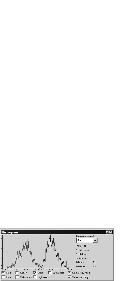
Chapter 6: Making Color and Tonal Corrections 145
To use the Solarize command:
1 Choose Effects > Artistic Effects > Solarize.
2 In the Threshold edit box, select a lightness threshold (1 to 254)
above which all colors are inverted. At a threshold of 1, all image
pixels are inverted and the effect is the same as applying the
Negative Image command.
3 Click OK.
Using the Histogram to Analyze Images
The histogram displays a distribution graph of red, green, blue,
greyscale, hue, saturation, and lightness values in an image. You can
analyze the distribution of detail in the shadows (shown in the left
part of the histogram), in the midtones (shown in the middle), and
the highlights (shown in the right part) and decide how to make
corrections.
After you analyze the histogram, you can correct the image with
Paint Shop Pro’s color and contrast correction commands or you can
use commands that adjust your image based on its histogram
features: Equalize, Histogram Adjustment, and Stretch.
To display the histogram for an image:
1 To limit the histogram data to a specific area, make a selection in
the image. See “Using the Selection Tools” on page 192.
2 Choose View > Palettes > Histogram or press F7.
The graph represents how many pixels are at each value of the
selected channels. The vertical axis represents the number of
pixels and ranges from zero pixels to the highest number of
pixels in the graph. The horizontal axis represents the value from
zero to 255 of a selected channel: Red, Green, Blue, Greyscale,
Hue, Saturation, and Lightness.
Do I need the histogram?
For image editing professionals,
the histogram is a powerful tool for
understanding and correcting
images.
For casual users, getting familiar
with the histogram may not be
necessary. Paint Shop Pro offers
many simpler ways to adjust
images. For information on how to
begin correcting your photos, see
“How to Approach Color, Contrast,
and Saturation Adjustments” on
page 96.

Chapter 6: Making Color and Tonal Corrections
146
For detailed information on the graph, see “Understanding
Histogram Values” on page 147 and “Guidelines for Analyzing
the Histogram” on page 147.
3 Mark or clear the check boxes below the graph to display or hide
the values for the channels.
4 Choose the image data that is graphed:
Sample merged If this check box is marked, the histogram graphs
all layers in the image. If this check box is cleared, the histogram
graphs only the current layer.
Selection only If this check box is marked, the histogram graphs
only the active selection. If the check box is cleared, the
histogram graphs the entire layer or image.
5 Do one of the following:
To view information about a specific value, place the cursor at
that point on the histogram.
To select a range of values, click and drag in the graph. When
you release the mouse, the range is deselected.
These fields show information about the selected point or range:
Value(s) The value or range of values (from 0 to 255) of the point
over which the cursor is positioned in the graph.
% in Range The percent of image pixels that are the value(s) of
the selected point or range. The number in parentheses is the
number of pixels that are the selected value(s).
% Above The percent of image pixels that are above the value(s)
of the selected point or range.
% Below The percent of image pixels that are below the value(s)
of the selected point or range.
6 To view the mean and median values for a channel, in the Display
channel drop-down list choose a channel: Red, Green, Blue, Hue,
Saturation, Lightness, or Greyscale. The Mean field displays the
average value for the selected channel. The Median field displays
the middle value in the range of values for the selected channel.
Note: The Display Channel has no effect on what is graphed in
the histogram.

Chapter 6: Making Color and Tonal Corrections 147
Understanding Histogram Values
The value of a selected channel is graphed from 0 to 255 along the
horizontal axis of the histogram. The meaning of the value depends
on the selected channel:
Red, Green, and Blue values represent the amount of red, green,
or blue in each color channel. A channel value of zero indicates
the color is not present and a value of 255 indicates the color is at
full strength. For example, if the graph has a spike at the value
128 for the Red channel, then there are a large number of pixels
with a red value of 128 (or middle red).
Hue, Saturation, and Lightness values are a different
representation of color than the Red, Green, and Blue channels.
Hue is the actual color and the value is the number assigned on
the color wheel; for example, red is zero, yellow is 43, green is
85, cyan is 128, blue is 170, and magenta is 212. (As a reference,
look at the color wheel on the Jasc Color Picker.) Saturation is
the level of grey added to the hue; zero is very grey and
unsaturated and 255 is no grey and fully saturated. Lightness is
the brightness of the hue; zero is no light (black), 128 is middle
grey, and 255 is fully light (white). The lightness histogram has
information similar to the greyscale histogram.
Greyscale values are levels of grey; zero is black, 128 is middle
grey, and 255 is white. These represent the brightness or
luminosity of an image. The distribution of grey values
determines the contrast of an image.
Guidelines for Analyzing the Histogram
Here are guidelines that can help you analyze the histogram and
make decisions about how to correct your images:
If a line spikes, there are many pixels at that value.
If a line is close to the horizontal axis, there are few pixels at that
level.
If the graph is spread out, the image has a balanced composition
and probably has enough detail to be corrected.
If the lines are compressed into a narrow area, the image
probably doesn’t contain enough detail to be corrected; try a new
scan.

Chapter 6: Making Color and Tonal Corrections
148
The usefulness of the histogram depends upon the image content
as well as its channel values. For example, an image of pale,
desaturated skin tones may display a big saturation peak on the
left side (in the lower values) of the histogram. An image of a
bright red fire engine may display a peak on the right side (in the
higher values) of the histogram. If the images were improperly
saturated, the saturation histograms might be reversed.
If the greyscale graph is mostly at the left side, the image is too
dark.
If the greyscale graph is mostly at the right side, the image is too
light.
If the greyscale lines are not spread out enough, you may need to
increase the contrast.
Correcting Images by Adjusting the
Histogram
Use the Histogram Adjustment command to adjust the contrast and
color balance of your image.
The graph in the Histogram Adjustment dialog displays how many
pixels are at each value of the selected channel. The vertical axis
represents the number of pixels and ranges from zero pixels to the
highest number of pixels in the graph. The horizontal axis represents
the value from zero to 255 of the selected channel.
When you change the histogram, the graph displays the adjusted
histogram as red and the original histogram as grey. To turn off the
red overlay, clear the Overlay result histogram check box.
For detailed information on the graph, see “Understanding
Histogram Values” on page 147 and “Guidelines for Analyzing the
Histogram” on page 147.
In the Histogram Adjustment dialog, you can edit the luminance
(lightness) and the red, green, and blue color channels. The
Histogram Window (opened by choosing View > Palettes >
Histogram) also graphs the hue, saturation, and greyscale values, but
these cannot be edited by adjusting the histogram.
Color depth
The Histogram Adjustment
command applies to greyscale and
16 million (24-bit) color images
only.
To increase the color depth of an
image, see page 261.
What the ToolTip reveals
When you place the cursor over the
histogram, a ToolTip displays the
following information:
Input is the value on the
horizontal axis
Count is the number of pixels
that have that value
Integral is the percentage of
pixels in the image with that
value
Output is the adjusted value.

Chapter 6: Making Color and Tonal Corrections 149
Note
The Histogram Adjustment dialog graphs one color channel at a
time, unlike the Histogram Window which can display all color
channels at once. You may want to first display the Histogram
Window (choose View > Palettes > Histogram), then use
autoproofing on the Histogram Adjustment dialog so you can see
changes graphed in the Histogram Window.
To use the Histogram Adjustment command:
1 To limit the adjustment to a specific area, make a selection in the
image. See “Using the Selection Tools” on page 192.
2 Choose Adjust > Brightness and Contrast > Histogram
Adjustment to open the Histogram Adjustment dialog.
3 For the Edit option, choose a channel:
Luminance Lightness values of the image. If you are correcting
contrast, start with this channel.
Color Pick a color channel from the drop-down list: Red, Green,
or Blue.
4 In the Presets drop-down list, choose Default. The default values
represent no adjustment to the image.
5 On the left side of the histogram, look for a gap between the left
edge and the point where the graph starts to rise. If there is a gap,
it shows that the darkest pixels in the image are not completely
black. Click and drag the Low slider (the black triangle) to the
point where the graph rises. The top Low edit box displays the
low position (from 0 to 255). The bottom edit box displays the
percentage of pixels that are between zero and the low value;
their contrast will be lost. As a general rule, keep the percentage
below 0.1%.
6 On the right side of the histogram, look for a gap between the
right edge of the window and the point where the graph decreases
to zero pixels. If there is a gap, click and drag the High slider (the
white triangle) to that point on the graph. This changes the
lightest pixels in the image to white. As a general rule, keep the
High percentage change (the bottom edit box) to below 0.1%.
7 If the overall image is too dark or too light, adjust the gamma.
(Gamma is a standard measure of change in an image’s contrast.)
If the image is too dark, drag the Gamma slider (the grey
triangle) to the right to increase the gamma (the number changes
in the Gamma edit box). If the image is too light, drag the
Gamma slider to the left to decrease the gamma.
Quick histogram
adjustments
To correct contrast using histogram
functions, you can use the
Equalize or Stretch commands.
See “Using the Histogram to Fix
Contrast Problems” on page 134.
Zoom in or out
Click to magnify the histogram
or click to reduce the view of
the histogram. Click 1:1 to display
the histogram at its original size.

Chapter 6: Making Color and Tonal Corrections
150
8 If the graph has peaks on the left and right sides and contains low
points in the center, the midtones need to be compressed.
Shadows and highlights need to be expanded to reveal the
information they contain. This often occurs in flash photography
when a subject is too close to the camera; the subject appears
brightly illuminated but the background of the photograph is very
dark. To compress the midtones, click and drag the Midtones
slider up.
9 If the graph peaks in the center and has a low number of pixels at
the left and right sides, expand the midtones by dragging the
Midtones slider down.
10 If you are improving your image, skip this step. If you are
creating artistic effects, use the Output Max and Min sliders on
the left side of the histogram to make further adjustments. The
Max slider is the white circle within a grey square; the Min slider
is the black circle within a grey square. To darken the image’s
whites, click and drag the Max slider down. To lighten the
image’s blacks, click and drag the Min slider up.
Note: Even though you are dragging sliders along the vertical
axis, the Max and Min values actually affect the horizontal axis.
They indicate the maximum and minimum value (from 0 to 255)
in the image. All pixels outside those values are converted so that
they fall within the maximum and minimum.
11 To adjust another channel, choose it in the Edit drop-down list
and follow these steps again.
12 Click OK.

151
Editing Images
Edit your images in many ways: copy from one image to another,
crop or resize an image, flip, mirror, or rotate an image, or change an
image’s scale or perspective.
Contents Adding Borders . . . . . . . . . . . . . . . . . . . . . . . . . . . . . . . . . . . . 152
Changing the Canvas Size. . . . . . . . . . . . . . . . . . . . . . . . . . . . 152
Combining Two Images . . . . . . . . . . . . . . . . . . . . . . . . . . . . . . 153
Correcting Image Perspective . . . . . . . . . . . . . . . . . . . . . . . . . 155
Cropping Images . . . . . . . . . . . . . . . . . . . . . . . . . . . . . . . . . . . 157
Cutting, Copying, and Pasting . . . . . . . . . . . . . . . . . . . . . . . . . 160
Deleting Images . . . . . . . . . . . . . . . . . . . . . . . . . . . . . . . . . . . 164
Flipping and Mirroring Images . . . . . . . . . . . . . . . . . . . . . . . . . 164
Repeating Commands . . . . . . . . . . . . . . . . . . . . . . . . . . . . . . . 165
Resizing Images . . . . . . . . . . . . . . . . . . . . . . . . . . . . . . . . . . . 166
Rotating Images . . . . . . . . . . . . . . . . . . . . . . . . . . . . . . . . . . . 168
Scaling and Transforming Images. . . . . . . . . . . . . . . . . . . . . . . 171
Using Rulers, Grids, and Guides . . . . . . . . . . . . . . . . . . . . . . . 173
Using Undo/Redo . . . . . . . . . . . . . . . . . . . . . . . . . . . . . . . . . . 177
Warping Images Using the Mesh Warp Tool . . . . . . . . . . . . . . . 178
Using the History Palette . . . . . . . . . . . . . . . . . . . . . . . . . . . . . 181
CHAPTER 7
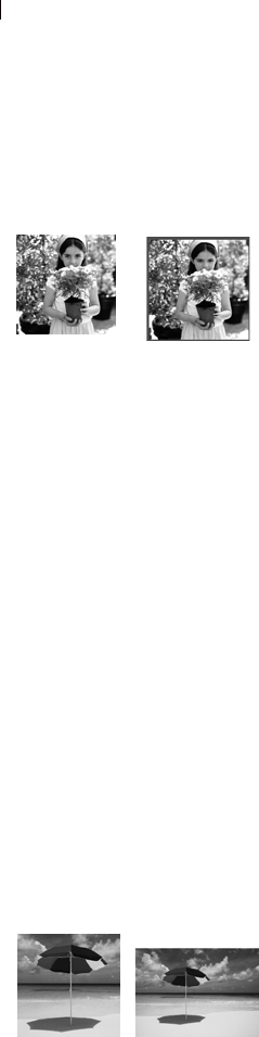
Chapter 7: Editing Images
152
Adding Borders
Use the Add Borders command to add a colored frame around an
image. The border increases the dimensions of the image by the
width of the border.
For multi-layer images, Paint Shop Pro prompts you to flatten the
image first. To add colored borders without flattening an image, use
the Canvas Size command instead; see “Scaling and Transforming
Images” on page 171.
To add borders:
1 Choose Image > Add Borders to open the Add Borders dialog.
2 Mark the Symmetric check box to create an equal width border
on all sides. Clear the check box to enter each border width
independently.
3 In the Size in pixels group box, select the dimensions of the
border.
Note: To change the dimensions from pixels, select the units in
the drop-down list in the Original Dimensions group box.
4 Click the Color box to choose the color for the border.
5 Click OK.
Changing the Canvas Size
The image canvas is the work area of the image and defines the
image’s dimensions—for example, 200 by 300 pixels. Sometimes
you need more canvas to add elements to an image; other times you
want to make the canvas size smaller. Use the Canvas Size command
to add or remove pixels at the edges of the image.
Note
Reducing the canvas size is not always the same as cropping an
image. For images with layers, reducing the canvas size does not
delete the pixels outside the new canvas area, it just shows less of the
layer. Background layer information will always be deleted, even
when there are other layers in the image.
Adding a colored border
Color choice tip:
Right-click the color box to pick
from the Recent Colors dialog
Original image and canvas
added at the top

Chapter 7: Editing Images 153
To change the image’s canvas size:
1 Choose Image > Canvas Size to open the Canvas Size dialog.
2 Choose settings from the New Dimensions group box:
Width, Height Enter values for the new canvas size.
Units Use this drop- list to change the measurement system.
Lock aspect ratio Mark this check box to constrain the new
canvas size to the current image proportions. The numeric edit
control (below the check box) indicates the image’s current
width-to-height ratio. Change this value to create a different
aspect ratio.
Background Click in the color box and pick a color for any added
canvas. Or, mark the Transparent check box to have any added
canvas be transparent.
Note: You must choose a color for any canvas added to the
background layer.
3 Set the placement of the image in the new canvas. In the
Placement group box, click a placement button. The fields to the
right of the placement buttons will show the amount of canvas
added or subtracted from each edge.
Note: You can also enter values in the fields to control image
placement.
4 Click OK.
Combining Two Images
Paint Shop Pro can combine two images into a third image. The new
image is the product of the color data from the two source images.
The color data from the two images is combined on a pixel-by-pixel
basis according to the function you select.
To combine two images:
1 Open the two images you want to combine.
2 Choose Image > Arithmetic to open the Image Arithmetic dialog.
3 Choose an image for Image #1 from the drop-down list. The size
of Image #1 determines the size of the new image.
4 Choose an image for Image #2 from the drop-down list.
Other resize options
You can also change the image
size by resizing, cropping, or
printing at a different size. For a
comparison of these options, see
the sidebar “Other ways to change
an image’s size” on page 166.
Color choice tip:
Right-click the color box to pick
from the Recent Colors dialog

Chapter 7: Editing Images
154
5 From the Function group box, select a method for combining the
images:
Add Image 1 Value + Image 2 Value
Subtract Image 1 Value - Image 2 Value
Multiply Image 1 Value x Image 2 Value
Difference Absolute Value of (Image 1 Value - Image 2 Value)
Lightest Maximum of (Image 1 Value, Image 2 Value)
Darkest Minimum of (Image 1 Value, Image 2 Value)
Average (Image 1 value + Image 2 Value)/2
OR Binary Or
AND Binary And
XOR Binary And/Or
6 From the Channel group box, select the color channel from each
image to use for combination. Mark the All channels check box
to use all the color channels in both images. This will produce a
24-bit image.
7 In the Modifiers group box, choose modifier options. The
modifiers are applied to the color values produced by the
Function and the Channel selections.
Divisor This number is used to divide the color values. It can
reduce the effects of the other selections.
Bias This number shifts each color value by a fixed amount. The
number is added to the color value produced by the Function,
Channel, and Divisor selections.
Clip color values This check box determines how Paint Shop Pro
handles final color values greater than 255 and less than 0.
8 Click OK.
Clip Color
Values Value less than 0 Value more than 255
Marked Value = 0 Value = 255
Cleared Value = Value + 256 Value = Value - 256
Chapter 7: Editing Images 155
Correcting Image Perspective
When you take pictures of tall objects, the resulting photographs
may have perspective distortion—the objects seem to be leaning or
angled. This distortion happens when the camera is at an angle to the
subjects.
Fix perspective distortion with two tools:
To use the Deform tool to correct perspective:
1 Select the layer to correct in the Layers palette.
2 Use grid lines to help you correct lines in your photograph that
should be vertical or horizontal. To turn on the grid, choose
View > Grid.
3 On the Tools toolbar, select the Deform tool .
4 Press Ctrl and click and drag a corner handle. The image updates
when you release the mouse button. Continue adjusting the
perspective until the image looks correct.
Note: If the correction causes some image data to fall outside the
image canvas, you can restore that data by increasing the size of
the canvas. See “Scaling and Transforming Images” on page 171.
Tool How to Use Applies to...
Deform
tool
Drag the corner handles of a
bounding box around an entire layer
to interactively change the
perspective.
See “To use the Deform tool to
correct perspective:” below.
The current layer
only.
Raster layers only.
Perspective
Correction
tool
Drag a bounding box around a
feature within the image (such as a
building) that is supposed to be
rectangular but is angled. Paint Shop
Pro adjusts the perspective to make
the selected feature rectangular.
See “To use the Perspective
Correction tool to correct
perspective:” on page 156.
The current layer
only.
Raster layers only.
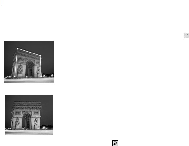
Chapter 7: Editing Images
156
To use the Perspective Correction tool to correct perspective:
1 On the Tools toolbar, select the Perspective Correction tool .
A bounding box with corner handles appears on the image.
2 On the Tool Options palette, select from these options:
Grid lines To display grid lines in the box, enter the number of
lines to display.
Crop image Mark this check box to crop the image back to its
original size after the perspective is applied. Areas of the
image that fall outside the original image size are deleted.
3 Drag each handle to the corner of a feature that is supposed to be
rectangular. For example, the feature may be a building with
sides that are angled but should be straight.
4 On the Tool Options palette, fine-tune the position of the
bounding box by specifying the X and Y positions of the four
corner handles.
5 Double-click the image or click Apply.
Note: To reset the perspective correction box to the original
rectangle, click Reset on the Tool Options palette.
Correcting perspective
Bounding box
After Correction
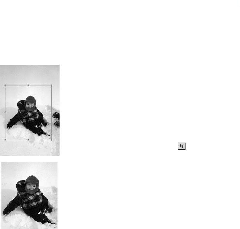
Chapter 7: Editing Images 157
Cropping Images
Crop images to create stronger compositions and change the image
focus. Cropping can reduce the memory needed to edit the image.
Also, by eliminating extraneous areas of color, cropping can
improve color corrections.
Use the Crop tool to select the crop area—a rectangle with edge and
corner handles that defines what part of the image to keep. You can
also crop based a selection or based on the opaque areas of an image.
Note
Cropping permanently removes the parts of the image outside the
crop area.
To define the crop area:
1 On the Tools toolbar, click the Crop tool .
2 Define the crop rectangle doing any of the following:
Click and drag the crop area rectangle over the image; or
On the Tool Options palette:
Enter values for the Height and Width of the crop area (if
necessary, change the unit of measurement with the Units
drop-down list); or
Enter positions for the Top, Bottom, Left, and Right sides of
the crop area; or
To use a standard image size, choose one of the many Presets.
Note: The image area outside the crop rectangle will be shaded.
To modify this shaded area, or to turn off the shading option, go
to the Transparency and Shading tab of the General Program
Preferences dialog. Note also that when crop shading is enabled
and you attempt to crop an 8-bit (256 colors) or less image, the
area outside the crop rectangle will be black. Thus when
cropping these types of images, you may want to disable this
option.
3 To adjust the crop area, do any of the following:
Click and drag an edge or corner handle; or
Move the entire crop rectangle by placing the cursor inside it
and then dragging the mouse; or
Adjust the Height and Width values; or
Cropping an image
Crop Area
After Cropping
Chapter 7: Editing Images
158
Adjust the Top, Bottom, Left, and Right sides of the crop area;
or
To remove the crop area and start over, right-click anywhere
in the image.
Note: To constrain the crop area to its current proportions, mark
the Maintain aspect ratio check box on the Tool Options palette.
Be aware that if you're using a cropping preset, this check box
will be unavailable.
4 When you're ready to crop the image, double click inside the crop
rectangle, or click the Apply button in the Tool Options
palette.
Note: After cropping an image, you may notice that the Width and
Height values in the Crop tool options are set to 1 and 1. This is not
a reflection of the cropped image size. To see the image size
dimensions after cropping, choose Image > Image Information, and
in the Image Information tab's Image section, look at the Dimensions
field.
To crop an image for printing:
1 On the Tools toolbar, click the Crop tool .
2 Define the crop area.
3 On the Tool Options palette, mark the Specify Print Size check
box.
4 In the Units drop-down list, select inches or centimeters. You
cannot use pixels for this method of cropping.
5 Enter the desired Height and Width for the final image. The
program will fit the final crop area into this size (reducing or
increasing the image resolution as needed).
6 To adjust the crop area, do any of the following:
Click and drag an edge or corner handle; or
Click and drag within the crop area to move the whole
rectangle; or
On the Tool Options palette, enter positions for the Top,
Bottom, Left, and Right sides of the crop area.
7 To crop the image, double-click the image or click Apply .
To crop an image for on-screen display:
1 On the Tools toolbar, click the Crop tool .
Chapter 7: Editing Images 159
2 On the Tool Options palette, clear the Specify Print Size check
box.
3 Define and adjust the crop area.
4 To crop the image, double-click the image or click Apply .
Cropping with a Selection
In Paint Shop Pro, you can make a selection and then crop the image
using that selection.
Note: If you crop to a selection that is feathered, the current
background color fills in the feathered region of the selection.
To crop using a selection:
1 Make a selection in the image.
Note: The selection can be any shape. Paint Shop Pro places a
crop area rectangle around irregularly shaped selections.
2 Do either of the following:
Choose Image > Crop to Selection.
Click the Crop tool, and then click Current selection in the
Snap crop rectangle to group box on the Tool Options palette.
Adjust the crop area and click Apply .
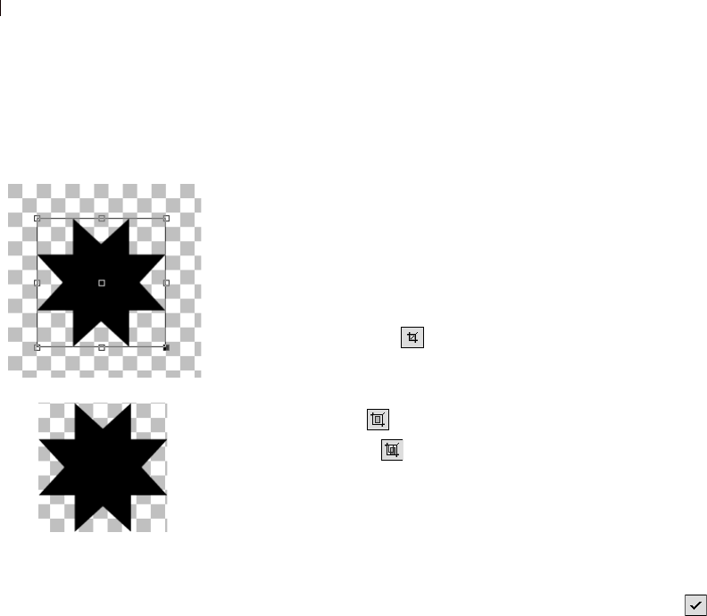
Chapter 7: Editing Images
160
Cropping Based on Opaque Areas
Use this feature to eliminate transparent areas at image edges. The
Crop tool can automatically set the crop area to cover just the opaque
(non-transparent) area of a single layer or an entire image.
Note
Opaque areas that are not rectangular, may have transparent areas
remaining after cropping.
To crop to the opaque area of a layer or image:
1 Click the Crop tool .
2 On the Tool Options palette, select an option from the
Snap crop rectangle to group box:
Layer Opaque Selects opaque areas of the current layer.
Merged Opaque Selects opaque area of all layers.
Note: If any layer or the background has a solid color (non-
transparent) background, the entire layer or image is selected as
the crop area.
3 Adjust the crop area as needed. See, “To define the crop area:” on
page 157.
4 To crop the image, double-click the image or click Apply .
Cutting, Copying, and Pasting
You can cut or copy a selection or an entire layer to the Windows
clipboard and then paste the contents of the clipboard into the same
image or another image. The basic commands are:
Cut Removes a selection or a layer to the clipboard and replaces it
with the selected background color or transparency.
Copy Copies a selection or a layer to the clipboard.
Copy Merged Copies a flattened (merged) version of all the layers in
a selection to the clipboard.
Paste Pastes a cut or copied selection or layer as a new image, a
selection, a new layer, or into the current layer.
Cropping to opaque area
After Cropping
What is the clipboard?
The Windows clipboard is an area
of computer memory used for
temporary storage. Cut or copied
image data is stored in it.

Chapter 7: Editing Images 161
To cut a selection or a layer:
1 Select the area or layer you want to cut. For information about
making selections, see Chapter 8, Making Selections in Images.
2 Choose Edit > Cut or press Ctrl + X.
To copy a selection or a layer:
1 Select the area or layer you want to copy.
2 Do either of the following:
To copy the selection or active layer, choose Edit > Copy or
press Ctrl + C.
To copy all layers of the selected area, choose
Edit > Copy Merged or press Ctrl + Shift + C.
To paste a cut or copied selection as a new image:
Choose Edit > Paste > Paste As New Image or press Ctrl + V.
To paste a cut or copied selection as a new layer:
1 Select the image into which you want to paste the selection.
2 Choose Edit > Paste > Paste As New Layer or press Ctrl + L.
Cutting vs. deleting
The Cut command places your
data in the Windows clipboard so
that you can paste it. The Clear
command throws away the data.

Chapter 7: Editing Images
162
To paste a cut or copied selection into a layer:
1 On the Layers palette of the target image, click the layer into which
you want to paste the selection.
2 Choose Edit > Paste and choose one of these commands:
Paste As New Selection (Ctrl + E) Pastes the contents of the
clipboard as a floating selection above the current layer. If the
image already contains a floating selection, it is defloated first.
Paste As Transparent Selection (Ctrl + Shift + E) Use this
command to remove a specific color from the selection you are
pasting. The command makes transparent any pixels in the
clipboard data that exactly match the current background color
(in the Materials palette). Then the command pastes the contents
of the clipboard as a floating selection above the current layer.
Note: Select the background color before you paste.
Paste Into Selection (Ctrl + Shift + L) Pastes the contents of the
clipboard into the current selection. The clipboard contents are
resized to fit the current selection.
Copying One Image into Another Using
the Browser
You can copy all the layers of an image in the Browser into an open
image by dragging the image thumbnail from the Browser onto the
open image.
To use the Browser to copy one image into another:
1 Open the image into which you want to copy the layers. This target
image must be a 16 million color or greyscale image.
2 On the Layers palette, click the layer which you want to place the
new image above.
3 Open the Browser (choose File > Browse or press Ctrl + B).
4 Navigate to the folder containing the image you want to copy.
5 Click the browser thumbnail and drag it into the target image.
When you release the mouse button, the layers are added to the
image. They are linked automatically.
Note: If a new layer duplicates the name of a layer in the target
image, a number is appended to the name.
When the pasted selection
looks out of proportion
When you paste data into another
image, the data keeps its original
pixel dimensions. If one image is
much larger or smaller than the
other, the selection may look out of
proportion.
After you paste the selection, use
the Deform tool to scale the
selection. See the sidebar “Quick
steps for proportional scaling” on
page 172.
Resize the two images to make
them similar size before copying
and pasting. See “Resizing
Images” on page 166.
Another way to remove a
color from a selection
Modify your selection by choosing
Selections > Modify > Select
Color Range. For detailed
instructions, see “Adding or
Removing a Color from a
Selection” on page 208.

Chapter 7: Editing Images 163
Copying Paint Shop Pro Images into
Other Applications
Copy a Paint Shop Pro image into other applications (such as word
processors or desktop publishing packages) in these ways:
Choose File > Save As to save the image to another file format
(such as TIF or BMP), and then open the other application and
import or place the file.
In Paint Shop Pro, copy the image (choose Edit > Copy to copy
the current selection or layer or Edit > Copy Merged to copy all
layers), and then open the other application and paste the image.
Open the Paint Shop Pro Browser, select the image, and then
press Alt while clicking and dragging the image to an open
document in the other application. A multi-layered image is
merged (or flattened) before it is copied into the other document.
The copy and browser options are available only for programs that
support graphic clipboard data.
Emptying the Clipboard
Placing large amounts of data in the clipboard can slow your
computer’s performance. Emptying the clipboard erases the
clipboard data.
Note
This command cannot be undone.
To empty the clipboard:
Choose Edit > Empty Clipboard.
Don’t have the other
document visible?
Drag the image to the application’s
icon on the Windows task bar, wait
for the application to open, move
the cursor over the document, and
then release the mouse button.
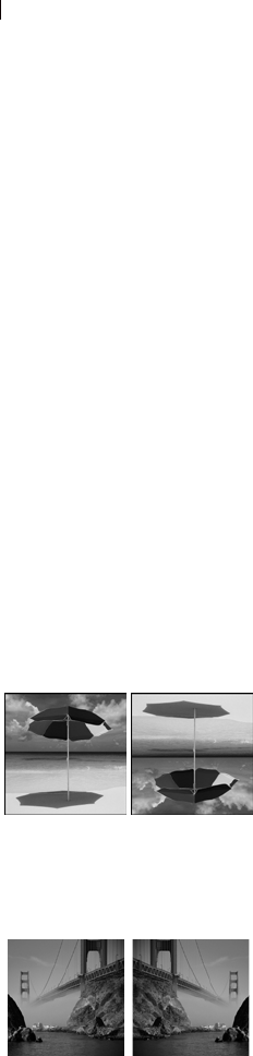
Chapter 7: Editing Images
164
Deleting Images
In Paint Shop Pro you can delete image files from the main
workspace or using the Browser.
To delete the current image in the workspace:
Choose File > Delete or press Ctrl + Delete.
To delete an image using the Browser:
1 Display the Browser, choose File > Browse or press Ctrl + B.
2 Navigate to the folder containing the file you want to delete.
3 Select the image to be deleted.
4 Choose File > Delete or press Ctrl + Delete.
Flipping and Mirroring Images
Use the Flip command to reverse an image along its horizontal
axis—the on top becomes the bottom and vice versa. Use the Mirror
command to reverse the image along its vertical axis—the left side
becomes the right and vice versa.
Note
To flip or mirror all layers in an image, make them all part of the
same layer group.
To flip a selection, layer, or image:
Choose Image > Flip or press Ctrl + I. Flipping a selection converts it
into a floating selection, leaving the original layer unchanged.
To mirror a selection, layer, or image:
Choose Image > Mirror or press Ctrl + M. Mirroring a selection
converts it into a floating selection, leaving the original layer
unchanged.
Flipping an image
Mirroring an image

Chapter 7: Editing Images 165
Repeating Commands
The Repeat command lets you apply the same command to other
images or to apply a command multiple times to the same image.
This command allows you to apply the same effect or correction
without opening a dialog each time.
The last command that can be repeated always displays in the Edit
menu. If the previous command cannot be repeated, the Repeat
command is inactive.
To repeat a command:
You can repeat a command (or apply a command to another image)
in multiple ways:
Choose Edit > Repeat; or
Press Ctrl + Y; or
Hold down Shift while selecting any toolbar button or menu item.
This will bypass the dialog and run the command with the last
used settings.
Repeating a Command Via the History Palette
With the History palette open, drag the desired command action
listed in the History palette and drop it onto another image. This will
make the second image active and apply the command to it. The
History palette is discussed toward the end of this chapter.
To repeat multiple actions:
Record a script and run it on each
image. For more information on
using scripts, please see “Scripting
Basics” on page 425.
Another way to repeat
actions:
Holding down Shift while selecting
any toolbar button or menu item
bypasses the dialog and runs the
command with the last used
setting.

Chapter 7: Editing Images
166
Resizing Images
After scanning or importing an image, you can adjust its size using
Image > Resize.
Pixels have no set, physical size. Each pixel just represents one area
of a single color. Resizing can reduce or increase the number of
pixels in the image (resampling the image). This reduces or
increases the file size. For instructions, see “To increase or decrease
the pixels in an image:” on page 166.
Resolution is the number of pixels printed per inch. More pixels per
inch (ppi), will create smaller printed pixels and a smaller printed
image. Fewer ppi, will create larger printed pixels and a larger
printed image. Resizing can also change the image’s resolution,
leaving the number of pixels in an image (and the file size)
unchanged. For instructions see, “To change the resolution (print
size) of an image:” on page 167.
For best results:
Don’t increase an image’s size more than 25 percent. Increasing
the size of an image causes a loss of detail and sharpness.
Only resize an image once. If your first resize is not correct, undo
it and try again.
Correct and retouch images before resizing.
To increase or decrease the pixels in an image:
1 Choose Image > Resize (Shift + S) to open the Resize dialog.
2 To resize the current layer only, clear the Resize all Layers check
box.
3 Mark the Resample using check box and select a resampling
type:
Note: Bilinear, bicubic, and weighted average resampling are
available only for greyscale and 16 million color images.
Smart Size Use this type in most cases. Based on the new pixel
dimensions you set, Paint Shop Pro chooses the best algorithm
listed below.
Weighted Average Uses a weighted-average color value of
neighboring pixels to determine how newly created pixels will
appear. Use this type when reducing photo-realistic, irregular, or
complex images.
Other ways to change
an image’s size
In addition to resizing an image,
you can also change the image
size by changing the canvas size,
cropping the image, or printing at a
different size.
Resizing the image removes
pixels to make it smaller or adds
pixels to make it larger.
Increasing the canvas size adds
pixels at the edge of the image.
Decreasing the canvas size
hides pixels at the edges of the
image (full layer information is
kept).
Cropping an image deletes the
pixels outside the selected crop
area.
Printing through Print Layout
resizes the image for printing but
the image file remains
unchanged. This is the best
option if you want to print the
image at various sizes.

Chapter 7: Editing Images 167
Bilinear Uses the two nearest pixels around each existing pixel to
determine how newly created pixels will appear.
Bicubic Minimizes the jaggedness that often results from
expanding an image by estimating how the newly created pixels
will appear. Use this type when enlarging photo-realistic,
irregular, or complex images.
Pixel Resize Duplicates or removes pixels as necessary to
achieve the selected width and height of the image. Use this type
with hard-edged images and simple graphics.
4 To constrain the new image dimensions to the image’s current
proportions, mark the Lock Aspect Ratio check box.
The aspect (width-to-height) ratio defaults to the ratio of the
active image. Changing the aspect ratio distorts the image by
stretching or contracting it in one dimension more than the other.
5 To keep the image’s current print size, mark the Maintain original
print size check box. The image resolution will change, keeping
the print size constant. For information on selecting image
resolution, see “About Image Size, Resolution, and Color Depth”
on page 36.
6 In the Pixel Dimensions group box, enter the new Width and
Height values. From the drop-down list, choose whether to enter
values in pixels or as a percent of the original size.
7 Click OK.
To change the resolution (print size) of an image:
1 Choose Image > Resize (Shift + S) to open the Resize dialog.
2 Clear the Resample using check box.
3 In the Print Size group box, enter the new Width and Height
values or the new Resolution value. Choose measurement
systems from the drop-down lists.
4 Click OK.

Chapter 7: Editing Images
168
Rotating Images
Rotating an image turns it around its pivot point. Rotating can
straighten an image that was scanned at a slight angle. Use the
Rotate command, the Deform tool, or the Straighten tool, as shown
in the table.
To Free Rotate:
1 To rotate a selection or layer (rather than the whole image), do
either of the following:
To rotate a selection, make a selection in the image.
To rotate a layer, on the Layers palette click the layer name.
2 Choose Image > Rotate > Free Rotate (Ctrl + R) to open the Rotate
dialog.
3 In the Direction group box, select the rotation direction: Right or
Left.
4 In the Degrees group box, select the number of degrees to rotate.
To enter a value between 0.01 and 359.99, select the Free option.
Command
or Tool How to Use Applies to...
Free Rotate
command
Choose the rotation angle from a
dialog and then apply the rotation.
See “To Free Rotate:” on page 168.
A selection, the
current layer, or all
layers of the image.
Rotate 90
degree
commands
Rotate image 90 degrees clockwise or
counter clockwise. See “To rotate all
layers 90 degrees:” on page 169.
All layers of the
image.
Deform
tool
Drag the rotation handle to see the
effect of the rotation immediately.
See “To rotate with the Deform tool:”
on page 169.
The current layer
only.
Raster layers only.
Straighten
tool
Specify a line along an image feature
that is supposed to be straight. Paint
Shop Pro aligns the image with this
rotation line.
Use this tool when the image has a
strong vertical or horizontal feature
(such as a building or a horizon). See
“To rotate with the Straighten tool:” on
page 170.
The current layer or
all layers in the
image.
Raster layers only.
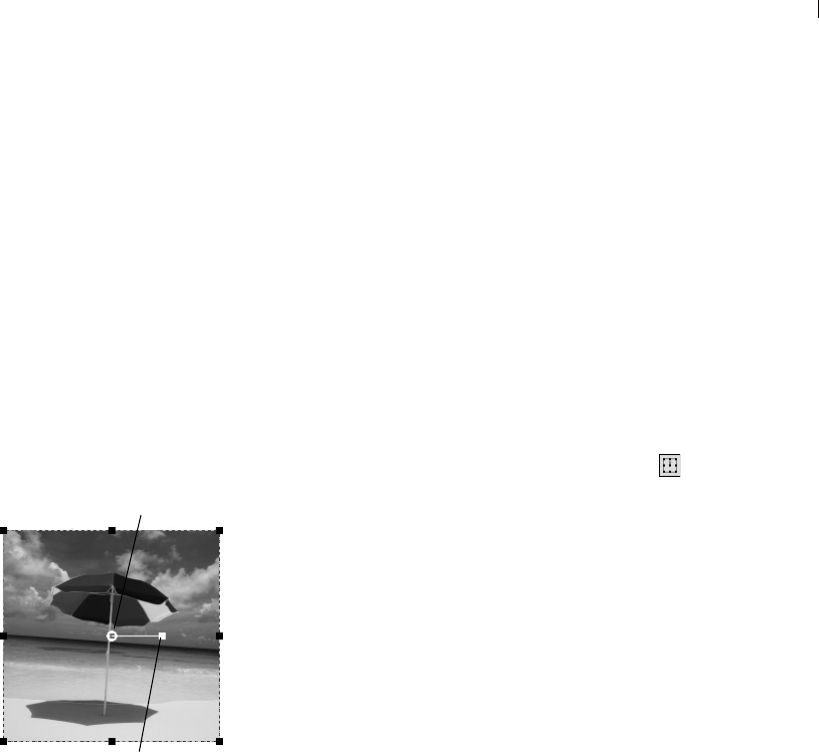
Chapter 7: Editing Images 169
5 To apply the rotation to all layers rather than just the current layer
or selection, mark the All layers check box.
6 Click OK.
Note: When you rotate a selection, the selection becomes a
floating selection and the original image is unchanged.
To rotate all layers 90 degrees:
1 Choose Image > Rotate and pick Rotate 90 Clockwise or Rotate 90
Counter clockwise.
To rotate with the Deform tool:
1 Select a layer on the Layers palette.
2 On the Tools toolbar, choose the Deform tool .
3 To change the center of rotation, drag the rotation pivot point (the
circle at the image’s center).
4 Click and drag the rotation handle (the square connected by a line
to the rotation pivot point) to a new position. Keep adjusting the
rotation as needed.
Note: Paint Shop Pro hides the image data that is rotated off the
canvas. You can view the data by increasing the size of the image
canvas. See “Scaling and Transforming Images” on page 171.
Deform Tool rotation
Placing Rotation Pivot
Points
In Paint shop Pro 9, pivot points
will snap to grids and guides.
Rotation Handle
Rotation Pivot Point
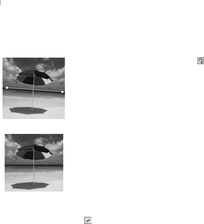
Chapter 7: Editing Images
170
To rotate with the Straighten tool:
1 To straighten a layer (rather than the whole image), click the layer
name on the Layers palette.
2 On the Tools toolbar, click the Straighten tool . A
straightening bar with end handles appears on the image.
3 Click and drag each handle of the straightening bar to align it
with the part of the image that you want to be straight.
4 On the Tool Options palette, choose from these options:
Auto Paint Shop Pro automatically straightens the image based
on the position of the straightening bar.
Make vertical Rotates the image to make the straightening bar
vertical.
Make horizontal Rotates the image to make the straightening bar
horizontal.
Angle To choose a specific angle for the straightening bar, enter a
value with the numeric edit control.
Crop image To crop the edges of the image to make it rectangular
after straightening, mark the check box. Clear this check box to
fill edge areas with the background color.
Rotate all layers To straighten all layers in the image, mark this
check box.
5 To apply the command, double-click the image or click Apply
.
Straightening an image
Position Straighten Bar
After straighten and crop
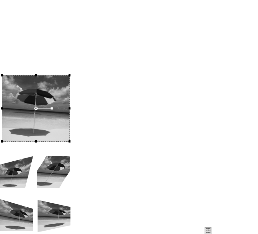
Chapter 7: Editing Images 171
Scaling and Transforming Images
The Deform tool gives you the power to transform images
interactively. Use the tool to scale, shear, distort, apply perspective,
or rotate a layer as follows:
Scaling resizes the selection or layer horizontally, vertically, or
proportionally.
Shearing skews a selection or layer vertically or horizontally.
Distorting stretches or contracts a selection or layer in any
direction.
Applying perspective corrects the perspective or applies a false
perspective on a selection or layer. For specific directions, see
“Warping Images Using the Mesh Warp Tool” on page 178.
Rotating moves a selection or a layer around a pivot point. For
specific directions, see “Scaling and Transforming Images” on
page 171.
The Deform tool works on raster layers only. To deform vector
objects or text in similar ways, see “Resizing and Reshaping Vector
Objects” on page 347 or “Applying Effects to Text” on page 413.
To deform an image:
1 Choose a layer by clicking its name on the Layers palette.
2 On the Tools toolbar, select the Deform tool .
A bounding box with handles appears on the selection or the
layer.
3 To deform the image by clicking and dragging in the image, do
one or more of the following:
To resize, click and drag one of the corner or edge handles.
To resize while keeping the current proportions, right-click
and drag a corner handle.
To move the entire image within the canvas, click and drag
anywhere within the bounding box.
To change the center of rotation, drag the rotation pivot point.
To rotate, drag the rotation handle.
To change perspective symmetrically, press Ctrl and drag a
corner handle horizontally or vertically.
Deforming an image
Color depth and layers
The Deform tool works on greyscale
and 16 million color images only. To
increase the color depth of an
image, see page 261.
To use the Deform tool, the image
data must be on a regular raster
layer. If necessary, promote the
background by choosing
Layers > Promote Background
Layer.
Bounding box
SkewDistort
Asymmetric
Perspective Symmetric
Perspective

Chapter 7: Editing Images
172
To change perspective asymmetrically, press Shift and drag a
corner handle.
To shear, press Shift while dragging a side handle.
To distort, press Ctrl and Shift while dragging a handle.
4 Adjust the deformation or view the deformation settings on the
Tool Options palette. For more information on these settings, see
“More Deform Options” below.
5 To cancel previous deformations, choose Edit > Undo (Ctrl Z).
Note
By default, you must press the Shift and Ctrl keys to deform an
image. To apply a deform operation without having to hold down
keys, choose a different Mode from the Tool Options Palette:
Scale The default setting; you must hold down a key or keys.
Shear (Shift) Allows you to shear without holding down Shift.
Perspective (Ctrl) Allows you to change perspective without
holding down Ctrl.
Free (Shift + Ctrl) Allows you to distort without holding down
Ctrl + Shift.
More Deform Options
You can precisely control many of the deform settings. The
following options appear on the Deform tool’s Tool Options palette:
Pivot X, Pivot Y Sets the X and Y coordinates of the rotation pivot
point.
Position X, Position Y Sets the X and Y coordinates of the top left
corner handle.
Scale X(%), Scale Y(%) Sets the percentage change for the horizontal
(X) and vertical (Y) resize.
Shear The offset of a side. Enter positive values to shear to the right
and negative values to shear to the left. At 0.5, a side shears 50% of
its length.
Angle The rotation around the pivot point. The image rotates clock-
wise from 0 to 360 degrees.
Reset Rectangle Resets the deformation rectangle to its original
shape but keeps any current deformations.
Deform Tool Tip
To make the deform handles on a
layer easier to see, drag the corner
of the image window to make it
larger than the image.
How do I resize and reshape
vector objects and text?
Use the Object Selection Tool. For
instructions, see “Using the
Selection Tools” on page 192.
Quick steps for
proportional scaling
To resize a floating selection or
layer and keep the same
proportions, select the Deform tool
and right-click and drag a corner
handle of the bounding box.
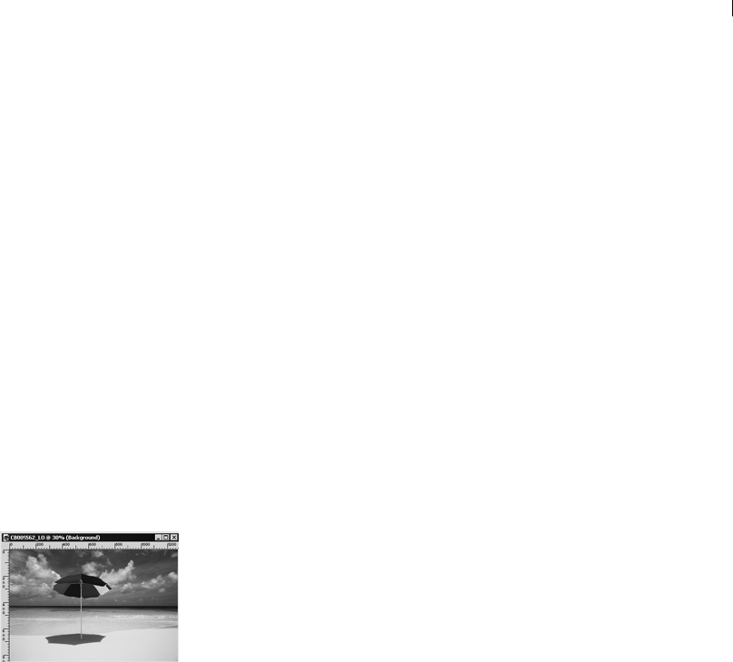
Chapter 7: Editing Images 173
Perspective X, Perspective Y The best way to create and adjust
perspective is by dragging the control handles. When you create a
perspective effect with the control handles, you are manipulating
many variables. Changing the values in the Perspective fields may
affect the scale, shear, and position values.
Using Rulers, Grids, and Guides
Use the rulers, grids, and guides to align and arrange artwork and
image elements.
Note
You must save your image in .PspImage format to save your grid and
guide settings.
Using Rulers
You can hide or display rulers. By default, rulers are hidden. When
the cursor is on the image, a thin line appears on each ruler to show
the cursor’s position. You can display rulers in pixels, inches, or
centimeters and change the color of the ruler.
To display or hide rulers:
Choose View > Rulers or press Ctrl+Alt+R.
To change ruler units and colors:
1 Choose File > Preferences > General Program Preferences.
2 Click the Units tab.
3 In the Display units drop-down list, select Pixels, Inches, or
Centimeters.
4 Choose the ruler color by selecting either Black on white or
Toolbar colors.
5 Click OK.
Displaying rulers on an image
Chapter 7: Editing Images
174
Using Grids
Grids are horizontal and vertical lines that help you position items.
You can display or hide grids and set preferences for grid spacing
and appearance. When you display grids, they appear in all open
image windows.
To display or hide the grid:
Choose View > Grid or press Ctrl + Alt + G.
To modify the grid:
1 Do either of the following:
Right-click the image’s title bar and from the context menu
choose Change Grid, Guide, and Snap Properties.
Choose View > Change Grid, Guide, and Snap Properties.
2 Click the Grids tab.
The Default settings group box shows settings for all future grids
you display. The Current image settings group box shows
settings for the grid in the current image.
3 For either the default or current settings, select from these
options:
Horizontal grids Sets the distance between horizontal grid lines
(starting from the top of the image).
Vertical grids Sets the distance between vertical grid lines
(starting from the left side of the image).
Units The unit of measure for positioning grid lines.
Color Click the color box to select a different color for grid lines.
Snap influence Controls how many pixels away an item must be
to snap to a guide or grid. The Snap to Grid option must be
selected in the View menu.
Displaying grids on an image
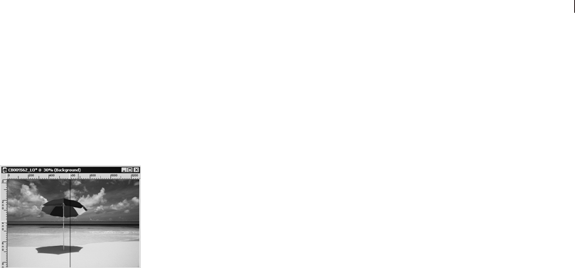
Chapter 7: Editing Images 175
Using Guides
Guides are horizontal or vertical lines that you drag onto your image
to use for positioning items or aligning. While grids place a series of
horizontal and vertical lines at certain intervals, you place guides at
the locations you want.
To place guides, you must first display the rulers by choosing
View > Rulers.
To display or hide guides:
Choose View > Guides.
To place a horizontal or vertical guide:
1 Do one of the following:
To place a horizontal guide, click the top ruler and drag a
guide to the desired position.
To place a vertical guide, click the left ruler and drag a guide
to the desired position.
As you drag, the Status Bar displays the guide’s position in
pixels.
To move a guide:
Do either of the following:
Click the guide handle on the ruler and drag it to a new position.
Double-click or right-click the guide handle to display the Guide
Properties dialog, type in a new Guide position value, and click
OK.
To change the color and position of a guide:
1 Double-click or right-click the guide handle to display the Guide
Properties dialog.
2 Select from these options:
Guide color Click the color box to choose a new color for the
guides.
Guide position Type values in this field to control the guide’s
position (in pixels).
3 Click OK.
Displaying guides on an image
Color choice tip:
Right-click the color box to pick
from the Recent Colors dialog

Chapter 7: Editing Images
176
To modify settings for guides:
1 To open the Grid, Guide, and Snap Properties dialog, do any of the
following:
Choose View > Change Grid, Guide, and Snap Properties.
Right-click the image title bar to display a context menu, and
choose Change Grid, Guide, and Snap Properties.
Double-click the ruler.
2 Click the Guides tab.
The Default settings group box shows settings for all the guides
you place in the future. The Current image settings group box
shows settings for the guides in the current image.
3 For either the default or current image settings, select from these
options:
Color Click in the color box to choose a new guide color.
Snap influence Controls how many pixels away an item must be
to snap to a guide or grid. The Snap to Grid option must be
selected in the View menu.
4 Click OK.
To delete one guide:
Do either of the following:
Drag the guide handle in the ruler off the image window.
Double-click the guide handle to display the Guide Properties
dialog and click Delete.
To delete all guides in an image or all open images:
1 Choose View > Change Grid, Guide, and Snap Properties.
2 Click the Guides tab.
3 Mark the Delete guides check box, and then select From current
image only or From ALL open images.
4 Click OK.

Chapter 7: Editing Images 177
Snapping to Grids and Guides
You can use the Snap features to align your brush strokes and objects
precisely to the nearest grid line or guide. The snap influence
controls how many pixels away an item must be to snap to guide or
grid.
Note
An item’s center point will snap to a guide or grid point if the center
point is the closest part of the item to a grid point or guide.
To snap to the nearest grid line:
Choose View > Snap to Grid (Ctrl + Shift + G).
To snap to the nearest guide:
Choose View > Snap to Guides (Shift + Alt + G).
Note: If a grid point and a guide are equal distances from an item,
the item will snap to the guide.
To change the snap influence:
1 Choose View > Change Grid, Guide, and Snap Properties.
2 Click the Grid or Guides tab and change the Snap influence
value.
The Default settings group box shows settings for all future
guides or grids. The Current image settings group box controls
settings for guides in the current image.
3 Click OK.
Using Undo/Redo
You can undo most actions as you edit an image. Use the Undo
command to remove brush strokes, color adjustments, effects, etc.
Use the Redo command to reapply a command that you have
undone.
Note: The History palette, described later in this chapter, provides a
more robust undo/redo functionality.
Items won’t snap?
Grids or guides must be displayed
for items to snap to them.
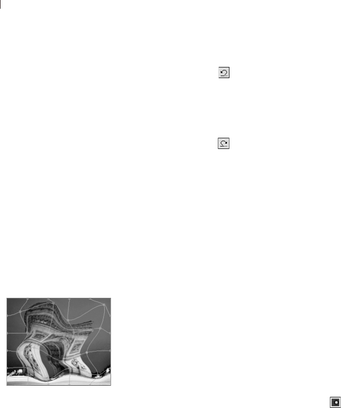
Chapter 7: Editing Images
178
To undo the last action:
Click the Undo button , choose Edit > Undo, or press Ctrl + Z.
If the action can’t be undone, the Undo button and menu command
are inactive.
To redo the last action:
Click the Redo button , choose Edit > Redo, or press
Ctrl+Alt+Z.
To revert to the last saved version of an image:
Choose File > Revert.
Warping Images Using the Mesh Warp Tool
Use the Mesh Warp tool to deform images, layers, and selections.
Clicking the tool places a grid, or mesh, on the image. The grid
intersections have mesh points, or nodes, that you drag to create
deformations.
Note
The Mesh Warp tool is limited to deforming the interior of a
selection. Use the Warp brush when you want to blend the selection
into the rest of the image.
To use the Mesh Warp tool:
1 On the Tools toolbar, select the Mesh Warp tool .
2 Drag the nodes to deform the image:
Click and drag a node to move it.
Press Shift while dragging a node to move the entire row or
column.
Press Ctrl while dragging a node to deform the row or column
into a smooth curve.
What you can’t undo
In Paint Shop Pro you can undo
most actions—with these
exceptions:
Renaming files
Saving files
Opening and closing files
Changes that are program-wide
and not specific to the current
image (such as changes to color
settings and preferences)
Actions that do not change
image pixels (such as zooming
and scrolling)
Warping with the Mesh Warp
tool
Other ways to warp images
Use the Warp Brush. See “Warping
Images With the Warp Brush” on
page 286.
Use the Warp Effect. See
“Applying Geometric Effects” on
page 223.

Chapter 7: Editing Images 179
3 Choose settings from the Tool Options palette:
Draft quality Choose the quality of the preview that displays
while you edit the mesh nodes.
Note: Increasing the quality can slow the warping process in
large images.
Final apply Clear the Best Quality check box to create a finished
mesh warp at the lower quality of the mesh preview.
Mesh horizontal and Mesh vertical The values indicate the
number of mesh lines within the frame. The border lines are not
counted.
Note: You can change the grid size as you work. Entering new
Mesh values reconfigures the grid and returns it to the original
position. The image retains any deformations you have made.
Symmetric Mark this check box to create a grid that evenly
covers the image. If your image is not square, there will be
different values for Mesh horizontal and Mesh vertical. Clear this
check box to adjust the Mesh horizontal and Mesh vertical
independently.
Show grid Clear the check box to hide the mesh warp grid.
4 You can save the position of the mesh nodes (the deformation
map) to apply the deformation to other images. For instructions
see “Saving and Loading Deformation Maps” on page 179.
5 Use Edit > Undo to undo changes to the mesh as you edit.
6 To apply the mesh warp, double-click the image or click Apply
. To cancel the mesh warp, click Cancel .
Saving and Loading Deformation Maps
You can save the deformations you have created to warp other
images. Paint Shop Pro creates a Deformation Map file that contains
the positions of the nodes and the number of mesh lines. Save the
mesh during the warping process or after you have applied the
deformation.
To save a deformation map:
1 On the Mesh Warp Tool Options palette, in the Deformation map
group box, click Save to open the Save Deformation Map
dialog.
Activate and move nodes
using the keyboard
Press Ctrl + PgUp or Ctrl + PgDn
to activate the next or previous
node in a row.
Press Shift + Ctrl + PgUp or
Shift + Ctrl + PgDn to activate the
next or previous node in a column.
Press the Ctrl + Arrow keys to
move the node 1 pixel.
Press the Shift + Ctrl + Arrow keys
to move the node 5 pixels.

Chapter 7: Editing Images
180
2 In the New deformation map group box, type a name for the map
file.
3 In the Checkerboard size drop-down list, choose a checkerboard
size that helps you preview the deformation effect. This
information is not saved with the map file.
4 Click Save to add the file to the default Deformation Maps
folder. Click the Edit Paths button to choose a different folder for
saving the deformation maps.
To load a deformation map:
1 On the Mesh Warp Tool Options palette, select an option under
Edge mode:
Background or transparency fill The areas between the edge
of the image and the edge of the warp are filled with:
the current background color if the areas are on a background,
transparency if the areas are on a layer.
Fixed The edge pixels are replicated to fill in the areas
between the edge of the image and the edge of the warp.
Wraparound The areas between the edge of the image and the
edge of the warp are filled with material from the opposite
side of the image.
2 Click Open Deformation Map to open the Load Deformation
Map dialog.
3 In the Deformation map group box, choose a map from the drop-
down list. Click the Edit Paths button to load a map from a
different folder.
4 In the Operation group box, select how you want the map to be
added:
Replace current map Replaces the existing mesh nodes with
the new map. Any adjustments you have made but not applied
are lost.
Add to current map Adds the settings from the new
deformation map to the mesh nodes. Any adjustments you
have made are retained.
5 In the Mapping group box, select how Paint Shop Pro should
adjust the size of the map to fit to the layer or image:
Fit to canvas The map size adjusts to fit the image canvas.
Fit to layer The map size adjusts to fit the current layer.
What is an Edge Mode
setting?
The Edge Mode setting determines
what happens if there is a gap
between the border of the image
and the edge of the image.

Chapter 7: Editing Images 181
Current size centered on The map retains its original size and
is positioned in the center of the Canvas or Layer.
6 In the Preview group box, choose a Checkerboard size from the
drop-down list to obtain the best preview of the deformation.
7 Click Load.
Using the History Palette
The History palette lists each command you apply to the active
image. The most recent action appears at the top of the list. The
History palette gives you the ability to quickly undo and redo actions
applied to the current image. In addition to its basic Undo and Redo
To Here functions, the History Palette also offers several additional
powerful and time-saving functions:
Selectively Undo any listed action. Depending on which action
you undid, actions that were applied after the undone action may
or may not remain applied to the image. This is described in
more detail in the section Undoing and Redoing History Palette
Actions below.
Save a Quickscript based on any number of selected History
palette actions, and then run the Quickscript on the current image
or another open image. This is described in more detail in Saving
and Applying Quickscripts below.
Save History palette actions as a regular PspScript file, or copy
them to the clipboard for pasting into another script file.
Drag and drop History palette actions onto another image to
instantly apply those actions.
Displaying and Hiding the History Palette
Display this palette by choosing View > Palettes > History, or by
pressing F3.
To hide the palette, click its Close button in the upper right corner of
the title bar, or choose the menu item again, or press F3 again.
Setting the Number of Saved Commands in the
History Palette
By default, the History palette will list the 250 most recently
executed commands on the active image. To set this value higher or
lower:

Chapter 7: Editing Images
182
1 Choose File > Preferences > General Program Preferences.
2 Click the Undo tab.
3 Make sure the Enable the undo system check box is marked.
4 Set the Limit undo/redo to n steps per open image to the desired
value. As mentioned above, the default value is 250. Steps older
than 250 will become undoable steps, only 10 of which will be
retained as defined by the next setting.
5 The Non-undoable steps after the last non-undoable step value,
as mentioned above, sets the number of non-undoable steps that
will be retained after the last non-undoable step limit has been
reached. The default value is 10.
Note: Non-undoable steps cannot be undone or redone anymore.
They can, however, be reapplied to the current image or other
open images, can be saved to the Quickscript, or as a regular
PspScript file, or copied to the clipboard.
Undoing and Redoing History Palette
Actions
The History palette lists all actions performed on the active image.
The most recent action is at the top of the list, and the first action
performed is at the bottom of the list. You can select an individual
action to modify by clicking its name in the History palette, or select
multiple actions by holding down Shift (to select adjacent actions) or
Ctrl (to select non-adjacent actions).
After applying any number of actions to an image, you can use the
History palette to:
Undo any listed action by clicking its Undo/Redo button , or
by highlighting the item name and then pressing the Undo to here
button on the History palette's toolbar. Both methods
perform an “Undo to Here” function, undoing the action you
clicked as well as all subsequent actions (which are listed above
the action you clicked). The undone actions will be denoted with
a yellow X .
Chapter 7: Editing Images 183
Redo an undone action by again clicking its Undo/Redo button,
or by highlighting the item name and then pressing the Redo to
here button on the History palette's toolbar. Both methods
perform a “Redo to Here” function, undoing the action you
clicked as well as all preceding actions (which are listed below
the action you clicked). The redone actions will no longer have
an X of any color over their eye icon.
Note: Selectively undone actions (denoted with a red X) that
precede the action you clicked will not be redone. These
actions can only be redone by purposely choosing Redo
Selected.
Selectively undo an action by holding down Ctrl and clicking its
Undo/Redo button, or by highlighting the item name and then
pressing the Undo selected button on the History palette
toolbar. Selectively undone actions will be denoted by a red X
. Be aware that a selectively undone action can yield
unintended or unexpected results depending on its relationship to
subsequent actions. Refer to the section Using the Selective
Undo Feature Carefully below for more information.
Redo a selectively undone action by highlighting the item name
and then pressing the Redo selected button on the History
palette toolbar. To redo selectively undone actions, Ctrl-click
them again.
Using the History Palette's Undo and Redo
Toolbar Buttons
The table below lists the function of each undo/redo-related button
in the History palette.
Undo to here Click a History palette item name and then click
this button to undo the item and all actions that followed it. Same
as clicking on that item’s Eye icon.
Redo to here Click an undone (yellow X) History palette item
name and then click this button to redo the action and any other
undone actions preceding it. Same as clicking on that item’s Eye
icon.
Undo selected Click a History palette item name and then click
this button to selectively undo the item. Be aware that this may or
may not affect subsequent actions, and may not yield the
intended results. Same as Ctrl-clicking that item’s Eye icon.
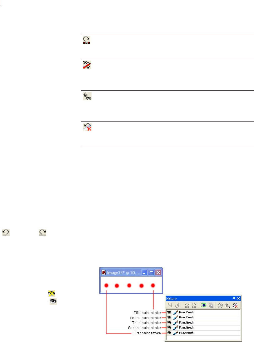
Chapter 7: Editing Images
184
Using the History Palette's Context Menu
Right-click on a selected History palette item (or group of selected
items) to display the context menu, which contains all History
palette-related commands.
Using the Selective Undo Feature Carefully
The History palette's selective undo feature is powerful and
convenient, but under certain circumstances may not be the ideal
course of action. Shown below are two examples showing the results
of the selective undo feature.
A Simple Example
1 Here is an image containing five individual paint strokes placed left
to right across the image.
Redo selected Click a selectively undone History palette item
name and then click this button to redo the action.Same as Ctrl-
clicking that item’s Eye icon.
Clear selectively undone commands Click this button to
convert all selectively undone actions into non-undoable
commands (commands that can no longer be undone or redone).
You'll be prompted whether or not to perform this action.
Show non-undoable commands Click this button to show or
hide the non-undoable commands. When shown, non-undoable
items will be listed in gray (denoting that they're inactive/
unavailable).
Empty history Click this button to convert all History palette
items into non-undoable commands. You'll be prompted whether
or not to perform this action.
What about the standard
Undo and Redo commands?
You can still use the
Standard toolbar's Undo
and Redo buttons,
or choose Edit > Undo /
Redo to undo or redo
actions in the order they
were performed. Using
these methods will update
the History palette Undo/
Redo button to the
appropriate state ( for
undone items, and for
redone items). Be aware,
however, that selectively
undoing an action can only
be performed via the
History palette.
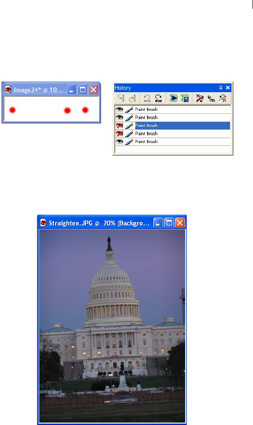
Chapter 7: Editing Images 185
2 Click here to see what happens when we selectively undo the
second and third strokes.
An Example of an Unintended Results
1 Here is a photo that could benefit from straightening as well as the
Fillflash filter applied to the foreground.
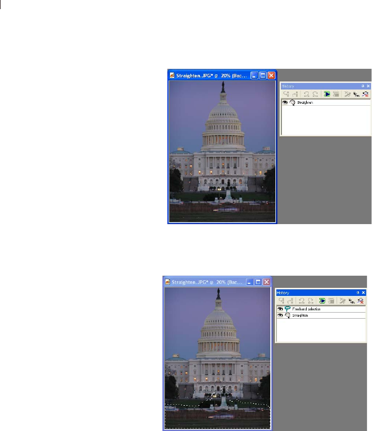
Chapter 7: Editing Images
186
2 Here is the photo after being straightened and cropped.
3 Here is a Freehand selection of the foreground area.
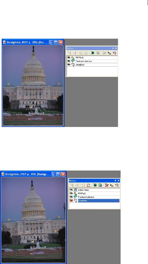
Chapter 7: Editing Images 187
4 Here is the Fillflash filter applied to the selection.
5 Here you can see what happens when you selectively undo the
straightening. Clearly this adversely affected the Freehand
selection and the Fill flash applied to it.

Chapter 7: Editing Images
188
Saving and Applying Quick Scripts
One of the powerful and convenient features of the History palette is
that it allows you to selectively choose steps applied to an image and
save those steps as a Quickscript. You can then apply the Quickscript
to another image (or to the current image).
Be aware that there is only one Quickscript; each time you select
History palette commands and click the Save Quickscript button, the
previously saved Quickscript is written over.
Saving Commands as a Quickscript
To save one more commands as a Quickscript:
1 Click the desired commands listed in the History palette (click the
command name, not its associated button). Note that as soon as one
command is selected, the Save Quickscript button activates.
2 Click the Save Quickscript button . The selected steps can
now be applied to any image the next time you click the Run
Quickscript button.
Note: Saving a group of selected commands as the Quickscript
overwrites the previously saved Quickscript without warning.
Applying a Quickscript to Another Image
After saving commands as the Quickscript, open another image (or
make another open image active) and then click the Run Quickscript
button .
A Note About Scripting and Plug-ins
Be aware that if you've executed commands involving plug-ins,
scripting these commands may not produce the intended results. In
particular, plug-in commands will not execute in Silent mode and
may not default to the parameters originally used.
Applying Selected Commands to Other
Images
Commands selected in the History palette can quickly be applied to
another image, or to all images open in the Paint Shop Pro
workspace.
Where is the Quickscript?
The Quickscript is saved to
the file
QuickScriptTemp.PspScript
and resides in the Scripts-
Trusted folder.

Chapter 7: Editing Images 189
To apply selected commands to all open images:
1 Select the desired commands— Shift-click to select adjacent
commands, or Ctrl-click to select non-adjacent commands.
2 Right-click on any selected command to display the History
palette's context menu, and then choose Apply to other open
documents.
To drag commands to another image:
To quickly apply one or more selected commands to another open
image, drag the command name(s) (not the icon) onto another open
image.
Saving Commands as PspScript Files
Commands selected in the History palette can quickly be saved to
the .PspScript file format, or copied to the clipboard.
Saving to the .PspScript Format
1 Click the desired commands listed in the History palette— Shift-
click to select adjacent commands, or Ctrl-click to select non-
adjacent commands.
2 Right-click on any selected command to display the History
palette's context menu, and then choose Save to script. This
displays the Save As dialog.
3 If necessary, navigate to the folder where the script will reside.
4 In the File name field, enter a name for the script.
5 In the Save only active commands check box, do one of the
following:
Mark this check box (it is marked by default) to not include
undone commands in the script.
Uncheck this box if you want to include the undone
commands in the script. Be aware, however, that the undone
commands will be active (not undone) when the script is
executed.
6 Click Save.

Chapter 7: Editing Images
190
Copying Commands to the Clipboard
To copy the Python syntax associated with selected commands to the
clipboard:
1 Click the desired commands listed in the palette— Shift-click to
select adjacent commands, or Ctrl-click to select non-adjacent
commands.
2 Right-click on any selected command to display the History
palette's context menu, and then choose Copy to the Clipboard.
3 Open a text editor such as Notepad, or a Python-aware text editor
application such as PythonWin or Idle.
4 In the text editor application, paste the clipboard contents. You'll
then see the syntax associated with the commands you selected.

191
Making Selections in Images
Selecting the parts of images to edit is an important step in
modifying images. After you create a selection, you can edit it while
leaving the rest of the image unchanged. You can use tools (such as
painting or drawing) or apply commands (such as flipping, copying,
or cropping) to the selection.
The border of a selection is identified by black and white dashes
called a marquee. This chapter shows you how to make many types
of selections.
Contents Using the Selection Tools . . . . . . . . . . . . . . . . . . . . . . . . . . . . 192
Using Edit Selection . . . . . . . . . . . . . . . . . . . . . . . . . . . . . . . . 201
Adjusting Selection Borders . . . . . . . . . . . . . . . . . . . . . . . . . . . 202
Converting a Selection into a Layer . . . . . . . . . . . . . . . . . . . . . 204
Creating Custom Patterns from Selections . . . . . . . . . . . . . . . . 205
Modifying Selections . . . . . . . . . . . . . . . . . . . . . . . . . . . . . . . . 205
Clipping a Selection to the Canvas. . . . . . . . . . . . . . . . . . . . . . 212
Moving Selections within an Image. . . . . . . . . . . . . . . . . . . . . . 213
Saving and Loading Selections. . . . . . . . . . . . . . . . . . . . . . . . . 214
Working with Standard and Floating Selections. . . . . . . . . . . . . 218
CHAPTER 8
Chapter 8: Making Selections in Images
192
Using the Selection Tools
The way in which you select part of the image depends upon the type
of layer: raster and art media, or vector.
Paint Shop Pro provides selection tools that create raster (or pixel)
selections as well as vector selection tools that select vector objects.
Raster (and Art Media) Selection Tools
Selection tool Makes a selection of a specific shape, such as a
rectangle, circle, or star. See “Making Selections with the
Selection Tool” on page 193.
Freehand Selection tool Makes a selection of an irregular shape
or around the edges of an object, such as the petals of a flower or a
child’s hand. See “Making Selections with the Freehand Selection
Tool” on page 195.
Magic Wand tool Makes a selection based on a color, brightness,
or opacity. See “Making Selections with the Magic Wand Tool” on
page 197.
These selection tools are grouped together in a flyout on the Tools
toolbar. One tool is displayed at a time. Click the down arrow to the
right of the tool to see the other selection tools.
Although these selection tools create raster selections, you can use
them on vector layers; they create raster selections from the vector
objects. For example, if you copy the selection and paste it as a new
image, the object is copied as individual pixels (rather than a vector
object) onto a raster layer.
Vector Selection Tools
To select vector objects and vector text (without turning them into
raster selections), use these tools:
Object Selection tool Selects vector objects or vector text. See
“Selecting Vector Objects” on page 199.
Text tool Creates a selection in the shape of text. See “Selecting
Text” on page 199.
Transforming a selection
Here are a few of the ways you can
edit selections:
Cut, copy, or paste selections.
Crop to a selection.
Move selections within the
image.
Flip, mirror, or rotate selections.
Correct colors within selections.
Apply effects to selections.
Paint or draw in selections.
Use multiple selections
tools
You can make an initial selection
with one selection tool, and then
switch to another selection tool to
add to or subtract from the
selection. For more information,
see “Modifying Selections” on
page 205, or “Subtracting from a
Selection” on page 207.

Chapter 8: Making Selections in Images 193
Making Selections with the
Selection Tool
Use the Selection tool to select a portion of a raster layer, or to create
a raster selection of objects on a vector layer. You can make a
selection of a specific shape: rectangle, square, rounded rectangle,
rounded square, ellipse, circle, triangle, pentagon, hexagon, octagon,
star, or arrow.
To use the Selection tool:
1 On the Tools toolbar, choose the Selection tool from the
Selection tool flyout.
2 On the Tool Options palette, choose from these options:
Selection Type Use this drop-list to choose the shape of the
selection area (rectangle, ellipse, star shape, etc.).
Mode Specifies whether you want to Replace, Add, or Remove
from an existing selection.
Feather Specifies a width in pixels (0 to 200) that the selection is
faded along the edges. When you move or paste the selection,
feathering helps blend the selection into the surrounding area and
makes it appear more natural. The higher the Feather value, the
softer the edges. Set the width to 0 to create a selection with no
feathering and distinct edges.
Anti-alias Mark this check box to use anti-aliasing, which
produces a smooth-edged selection by partially filling in pixels
along the edge, making them semi-transparent. Clear the check
box to keep the original edges.
Note: After you create a selection, you cannot change the
Selection Type or the Anti-alias setting. Changing these options
applies to the next selection you make. You can change the
feathering; see “Changing the Feathering of a Selection” on
page 207.
3 To make the selection, do one of the following:
Drag in the image. As you drag, a border indicates the
selection. When you release the mouse, the selection border
becomes a marquee. If you select a Feather value, that portion
of the selection is added to the marquee.
Feather before or after
If you select a Feather value in the
Tool Options palette, that value
affects the next selection that you
make with the Selection tool. You
can also change the feathering of
an existing selection; choose
Selections > Modify > Feather or
Selections > Modify > Inside/
Outside Feather.
Chapter 8: Making Selections in Images
194
To make a selection of a specific size, on the Tool Options
palette, click Custom Selection and then enter the
selection position in pixels for the left, top, right, and bottom
positions. The positions are measured from the top left corner.
On the Tool Options palette, choose Layer opaque to select
opaque areas (the non-transparent area that has data) of the
current layer.
Choose Merged opaque to select the opaque area of
all layers within the image. This option is unavailable if the
image has only one layer.
4 To create a rectangular selection from an odd shaped selection:
In the Create selection from area of Tool Options, choose
Current selection . A new rectangular selection surrounds
the current selection.
5 To modify the selection borders, do any of the following:
To add to the selection, from the Mode drop-down list, choose
Add, or hold down the Shift key and click and drag another
selection area (it does not need to be part of the original
selection).
To subtract from the selection, from the Mode drop-down list,
choose Remove, or hold down the Ctrl key and click and drag
within the original selection.
To move the selection marque, right-click and drag with any
selection tool, or choose the Mover tool and right-click and
drag within the selection.
Note: You can also switch to another selection tool before adding
to or subtracting from the selection.
You can now edit the contents of the selection (move it, copy it,
paint it, correct colors, apply effects, and so on). The selection
remains active until you make another selection or right-click
outside the selection boundary to deselect it while one of the
selection tools is active, or choose Selections > Select None.
Align that selection
You can use grids and guides in the
image window to help you align
your selections. For more
information, see “Using Rulers,
Grids, and Guides” on page 173.
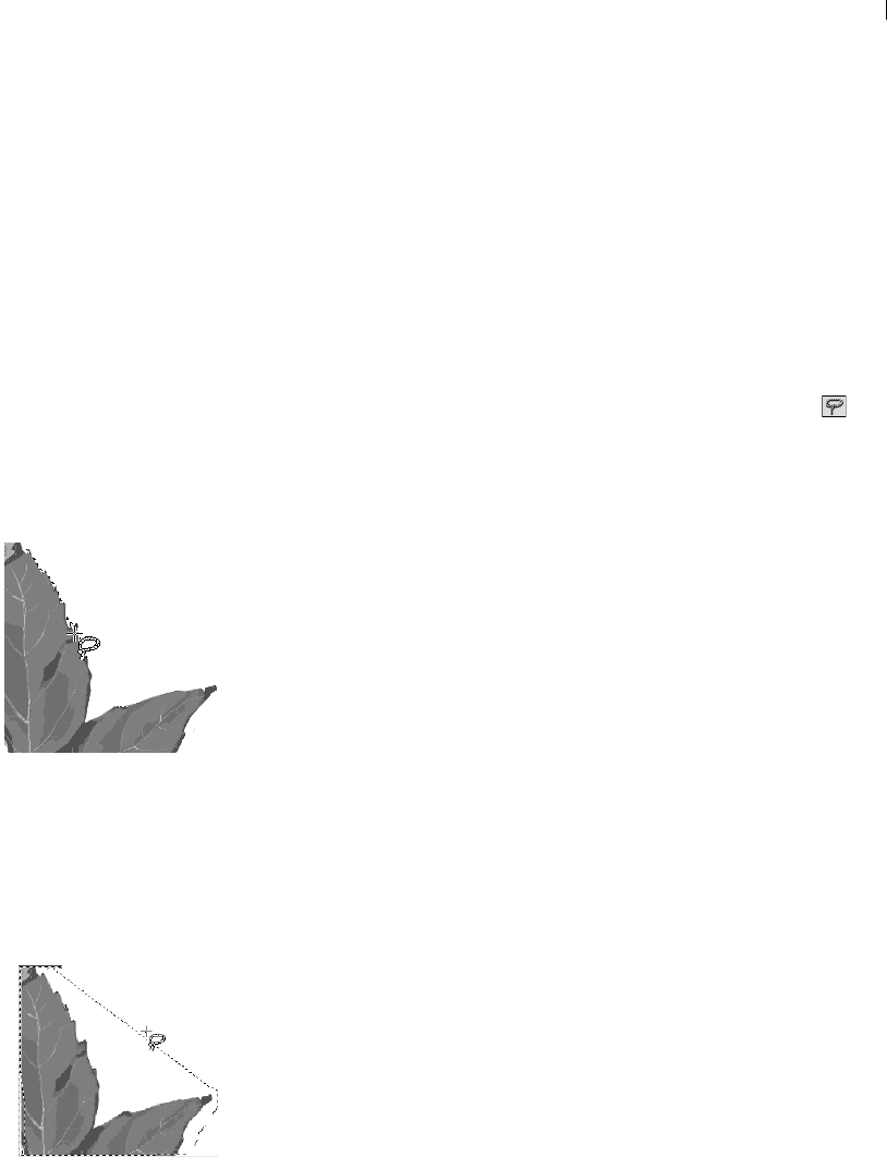
Chapter 8: Making Selections in Images 195
Making Selections with the
Freehand Selection Tool
With the Freehand Selection tool, you can select objects with
irregular borders. Use this tool to select everything from the outline
of a tree to a child’s hand to the jagged edge of a leaf.
To use the Freehand Selection tool:
1 If the image has more than one layer, click the layer on which you
want to make a selection from the Layers palette.
2 On the Tools toolbar, choose the Freehand Selection tool
from the Selection tool flyout.
3 On the Tool Options palette, choose the Selection Type to
determine how Paint Shop Pro makes the selection:
Edge Seeker Click on the edges of irregularly shaped areas, and
Paint Shop Pro finds the edges between two areas with subtle
color or light changes between them.
Freehand Click and drag to select the area—like making a
freehand drawing. Use this type for irregular shapes when you
want to make a selection quickly.
Point to Point Click from point to point and Paint Shop Pro
draws a straight border between the points. Use this when you
want a selection with straight edges.
Smart Edge Click along the edges of irregularly shaped areas and
Paint Shop Pro finds the edges. Use this selection to create a
border between two areas of highly contrasting color or light.
4 On the Tool Options palette, choose from these additional
options:
Feather A width in pixels (0 to 200) that the selection is faded
along the edges. Feathering controls the sharpness of a
selection’s edges. For a detailed description, see page 193.
Range Specifies the distance (0 to 15) from the point you click
that Paint Shop Pro searches for an edge. This option is available
only for the Edge Seeker selection type.
Smoothing The amount of smoothing (from 0 to 40) for the
selection border. This smooths sharp edges or jagged lines.
Anti-alias Mark this check box to use anti-aliasing, which
produces a smooth-edged selection by partially filling in pixels
along the edge, making them semi-transparent. Clear the check
box to keep the original edges.
Select the layer first!
Before you make a selection,
display the Layers palette and click
the name of the layer that contains
the data you want to select.
Using the Edge Seeker
selection type
Using the Freehand selection
type

Chapter 8: Making Selections in Images
196
Sample Merged If the check box is marked, the tool searches for
an edge in all layers of the area you select. If the check box is
cleared, the tool searches for edges only in the current layer. It is
only available when the image has multiple layers and when
using the Edge Seeker and Smart Edge selection types.
5 Make the selection:
For the Edge Seeker and Smart Edge selection types, click in
the image where you want to start the selection, then click
points around the area you want to select. After you click each
point, a line indicates the selection border. To delete a
previous point, press Delete. To complete the selection,
double-click or right-click.
For the Freehand selection type, drag an outline of the area
you want to select. When the line encloses the selection,
release the mouse button. (If you release too soon, start again
or add to the selection as described in the next step.)
For the Point to Point selection type, click where you want the
selection border to start and then continue clicking until you
return near the starting point. To complete the selection,
double-click or right-click. To delete a previous point, press
Delete.
For all selection types, the line becomes a marquee indicating the
selection border.
6 To modify the selection area, do either of the following:
To add to the selection, from the Mode drop-down list choose
Add, or hold down the Shift key and click and drag another
selection area.
To subtract from the selection, from the Mode drop-down list
choose Remove, or hold down the Ctrl key and click and drag
within the original selection.
Note: You can also switch to another selection tool before adding
to or subtracting from the selection.
You can now edit the contents of the selection (move it, copy it,
paint in it, correct colors, apply effects, etc.). The selection remains
active until you make another selection or right-click to deselect it,
or choose Selections > Select None.
Using the Point to Point
selection type

Chapter 8: Making Selections in Images 197
Making Selections with the
Magic Wand Tool
Use the Magic Wand tool to select content rather than defining edges
in the image. It works well for selecting a complex part of an image
that has distinctly different pixels from other parts—for example, a
pink rose surrounded by green leaves. The tool uses four types of
values for making selections—color (RGB value), hue, brightness,
or opacity.
With the Magic Wand, you select the type of match you want (such
as hue), choose a tolerance that determines how closely pixels must
match, and then click once in the image to select the pixel that the
other pixels are compared to.
To use the Magic Wand tool:
1 If the image has more than one layer, on the Layers palette click the
layer name which contains the part of the image you want to select.
2 On the Tools toolbar, choose the Magic Wand tool from the
Selection tool flyout.
3 On the Tool Options palette, choose the Match mode to determine
how Paint Shop Pro creates the selection:
None Chooses all pixels.
RGB Value Chooses pixels that match the red, green, and blue
value of the color that you select in the image.
Color Chooses pixels of the same color that you select in the
image.
Hue Chooses pixels based on the position in the color wheel of
the hues you select within the image.
Brightness Chooses pixels based on the brightness of the color
you select within the image.
All Opaque Chooses only areas containing pixels. No transparent
areas are selected.
Opacity Chooses pixels based on their opacity.
4 On the Tool Options palette, choose from these additional
options:
Tolerance Controls how closely the selected pixels must match
the initial pixel you click. At low settings, the values must be
close. At higher settings, the Magic Wand tool selects a wider
range of pixels.
Select what you don’t want
Sometimes the easiest way to
select a complicated part of an
image is to select the part of the
image that you don’t want and then
invert the selection. For example, if
you have a picture of a tree
silhouetted against a blue sky, use
the Magic Wand tool to select the
sky and then invert the selection to
select the tree.
For more information, see
“Selecting Everything Outside the
Selection” on page 204.

Chapter 8: Making Selections in Images
198
Feather A width in pixels (0 to 200) that the selection is faded
along the edges. Feathering controls the sharpness of a
selection’s edges. For a detailed description, see page 193.
Sample Merged Mark this check box to have the Magic Wand
tool search for matching pixels in the merged image. Clear this
check box to limit the selection to the active layer.
Contiguous Mark this check box to select pixels that connect to
your original pixel. Unchecked, this option selects any image
pixel meeting the other criteria you’ve set.
Anti-alias Mark this check box and then choose whether you
want to anti-alias inside or outside of the selection marquee.
5 Click the part of the image that has pixels you want to match. The
selection marquee surrounds all matching pixels.
If the Magic Wand tool selected more pixels or fewer pixels than
you wanted, adjust the Tolerance value and make a new
selection.
6 To modify the selection, from the Mode drop-down list, choose:
Replace to replace an existing selection with a new selection.
Add to add to the selection, click another area of the image.
(Holding down Shift will also do this.)
Remove to subtract from the selection, click within the
original selection to remove the selection. (Holding down Ctrl
will also do this.)
Note: Use the Expand or Select Similar commands to add to the
selection. See “Modifying Selections” on page 205.
You can now edit the contents of the selection (move it, copy it,
paint in it, correct colors, apply effects, etc.). The selection remains
active until you make another selection or right-click to deselect it.

Chapter 8: Making Selections in Images 199
Selecting Vector Objects
To edit a vector object or vector text, you must first select the object
with the Object Selection tool. You can select one or several objects,
on the same layer or on different layers. You can also select vector
objects from the Layers palette.
To select vector objects with the Object Selection tool:
1 On the Tools toolbar, choose the Object Selection tool .
2 Do one of the following:
Click the object you want to select. To select multiple objects,
press Shift and click each additional object.
Drag the cursor to create a selection rectangle around the
object(s). The rectangle must enclose all objects completely to
select them.
A bounding box with handles surrounds the objects you selected.
For information on using these handles to edit the objects, see
“Resizing and Reshaping Vector Objects” on page 347.
To select vector objects from the Layers palette:
1 On the Layers palette, click the plus sign (+) to next to a layer to
expand the layer and display the objects within the layer.
2 Click the name of the object. To select multiple objects, press
Shift and click each object name. A bounding box in the image
surrounds the objects you selected.
Selecting Text
You can make two types of selections with text:
Use the Object Selection tool to select vector text so that you can
edit it.
Use the Text tool to create a raster text selection (a selection
marquee shaped like text) that you can use to create interesting
effects. For example, create a text selection on a solid colored
layer and then delete the selection so the letters become
transparent and are outlined in the solid color.
To select vector text:
1 On the Layers palette, click the layer name that contains the text.
2 On the Tools toolbar, choose the Object Selection tool .
Versatile Object Selector
In addition to selecting vector
objects, use the Object Selection
tool to:
Move, resize, reshape, and
rotate vector objects and vector
text.
Align and distribute vector
objects.
Group and ungroup vector
objects.
Apply Edit menu commands
such as copying and pasting.
For more information, see
Chapter 13, Drawing and Editing
Objects.
To deselect all
To undo the Select All command,
choose Selections > Select None.

Chapter 8: Making Selections in Images
200
3 Click the text. A bounding box with editing handles surrounds
the text.
You can now move or resize the text. Double-click to edit the
vector properties (such as the color or texture). To edit the words
themselves, click the Text tool and then click the text. You can
also right-click on the text in the Layers palette and choose Edit
Text from the context menu.
To create a text selection with the Text tool:
1 Select the Text tool .
2 On the Tool Options palette, in the Create as group box choose
Selection (which creates a selection shaped like the text rather
than text as a painted object).
3 Click where you want to start the text selection to open the Text
Entry dialog.
4 Select the text options and type the text.
5 Click Apply.
Deselecting a Selection
You can deselect any selection in the image, which removes the
marquee and integrates the selection back into the image. If you
deselect a floating selection, Paint Shop Pro defloats it and places it
in the underlying layer if the layer is raster. If the underlying layer is
vector or art media, Paint Shop Pro creates a new raster layer and
defloats the selection to it.
To deselect a selection:
Choose Selections > Select None, right-click in the image outside
the selection marquee, or press CTRL + D.
Selecting All Non-Masked Areas
Create a selection that selects all non-masked areas and omits all
masked areas. The selection is clipped to the canvas size.
To select all non-masked areas:
1 Create a mask as described in “Creating Masks” on page 391.
2 On the Layers palette, select the mask layer.
About the Text tool
Making a text-shaped selection is
just one thing that the Text tool can
do. The tool’s main function is to
add text to your image. For more
information, see Chapter 16,
Working with Text.
Creating a mask from
aselection
You can also use a selection to
create a mask. For more
information, see “Creating Masks
from Selections” on page 394.

Chapter 8: Making Selections in Images 201
3 Choose Selections > From Mask. The selection marque surrounds
the non-masked areas.
Note
If you saved a mask to an alpha channel, you can load it as a
selection by choosing Selections > Load from Alpha Channel.
Selecting All Pixels
Use the Select All command to select everything on a single layer or
in the entire image if the image has only one layer. The Select All
command selects everything on the image canvas.
To select all pixels in a layer or an image:
1 If the image has more than one layer, on the Layers palette click the
name of the layer you want to select.
2 Choose Selections > Select All or press Ctrl + A. A marquee
appears around the layer on the canvas.
Creating Raster Selections from Vector
Objects
You can select a vector object, convert it to a raster selection, and
then copy and paste this selection into another layer or another
image. Do this when you want to apply raster-only tools and
commands to vector objects.
To create a raster selection from a vector object:
1 Use the Object Selection tool to select one or more vector objects.
2 Choose Selections > From Vector Object.
The selection marquee surrounds each vector object. You can
now copy and paste the selection as needed. The original vector
objects remain unchanged.
Using Edit Selection
Use the Edit Selection command to create a selection from a brush
stroke, or to apply an effect to only the selection marquee.
Selecting a layer
As long as there are no selections
on the image, when you click a
layer’s name on the Layers palette
Paint Shop Pro automatically
selects all contents of the active
layer (though without a selection
marquee). If the layer has data that
is moved off the image canvas, that
data is also selected.
Chapter 8: Making Selections in Images
202
To create a selection:
1 Choose Selection > Edit Selection, or click the Edit Selection
button on the Layers palette. A selection layer is added to the
Layers palette.
2 Select a painting tool from the Tools toolbar. For more
information, see Chapter 11, Raster Painting.
3 Set the options for the painting tool in the Tool Options palette
and the Variance palette.
4 Paint on the image with black, white or shades of grey.
The lightness of the paint controls the opacity of the selection.
A ruby overlay displays the brush strokes.
5 Choose Selection > Edit Selection, or click the Edit Selection
button on the Layers palette. The selection marquee displays
the selected area.
To apply tools and effects to the selection marquee:
1 Make a selection on the image. See “Using the Selection Tools” on
page 192.
2 Choose Selection > Edit Selection, or click the Edit Selection
button on the Layers palette. A ruby overlay displays in the
selected area.
3 Apply a tool or effect to the selection area.
4 For more information, see Chapter 11, Raster Painting, or
Chapter 9, Applying Effects.
5 When finished editing the selection, choose Selection > Edit
Selection to display the selection marquee.
To turn off the selection marquee but retain the selection itself,
choose Selections > Hide Marquee. To remove the selection, choose
Selections > Select None.
Adjusting Selection Borders
After you make a selection in your image, you may want to modify
or edit the selection borders.

Chapter 8: Making Selections in Images 203
Moving the Selection Marquee
To change or fine-tune the area the selection encloses, you can use
the Mover tool to move the marquee.
To move the selection marquee:
1 On the Tools toolbar, choose a selection tool.
2 Right-click inside or on the marquee and drag the marquee to a
new position.
Hiding and Viewing the Selection
Marquee
The selection marquee is normally visible. Sometimes when working
with a selection it is helpful to hide the marquee temporarily without
disabling the selection. For example, you may want to see the results
of pasting a selection or feathering a selection’s edges.
To hide or view the marquee:
Choose Selections > Hide Marquee or press Ctrl+Shift+M.
Tips:
If you right-click in the image
outside the marquee, you deselect
the selection. If you click and drag
the selection with a selection tool,
you float the selection and move it.
(If you did one of these by mistake,
press Ctrl + Z to undo.)

Chapter 8: Making Selections in Images
204
Selecting Everything Outside the
Selection
Sometimes the easiest way to select a complicated part of an image
is to select the part of the image that you don’t want and then invert
the selection. For example, if you have a picture of a person against
a solid color background, you can select the background and then
invert the selection to select the person.
To invert a selection:
1 Make a selection in the image.
2 Choose Selections > Invert. The marquee changes to enclose the
opposite area of the image.
Converting a Selection into a Layer
To convert a selection into a layer, use the Promote to Layer
command on the Selections menu. The original selection contents
are unchanged; a copy of the selection becomes a new layer. By
converting the selection into a layer, you can modify it without
changing the original image data.
To promote a selection to a layer:
1 Make a selection in the image.
2 Choose Selections > Promote to Layer.
The new layer is placed above the original selection’s layer and is
named Promoted Selection.
Inverting a selection
Color depth
The Promote to Layer command
works on 16 million color and
greyscale images only. To increase
the color depth of an image, see
page 261.
Placing a selection in
another image
To place a selection as a layer
within another image, copy the
selection, open the other image,
and choose Edit > Paste > As New
Layer.

Chapter 8: Making Selections in Images 205
Creating Custom Patterns from Selections
You can turn a selection into a custom, seamless pattern which you
can use for applications like painting, adding text, or creating Web
page backgrounds.
To create a custom pattern:
1 Make a selection in the image.
2 Choose Effects > Image Effects > Seamless Tiling to open the
Seamless Tiling dialog.
3 Choose the tiling method, direction, settings, and corner style,
and then click OK.
Modifying Selections
After you make a selection in your image, you may want to modify
or edit the selection.
Adding to a Selection
You can add to the selection area using the selection tools, either the
same selection tool you used to make the original selection or a
different selection tool. For example, you have a picture of a person
carrying a large sign. You can select the sign with the rectangular
Selection tool, then add the person to the selection using the
Freehand Selection tool.
You can also use the Expand command to increase a selection by a
specific number of pixels or the Select Similar commands to add to
selections based on pixel color values.
To add to a selection using the selection tools:
1 On the Tools toolbar, choose the selection tool (Selection,
Freehand, or Magic Wand tool) that you want to use to add to the
selection.
2 On the Tool Options palette, select the tool options.
3 Hold down the Shift key as you click the parts of the image you
want to add to the selection. The areas do not need to be adjacent.
How to use the pattern
To use the pattern that you create,
save it in the Patterns folder of the
Paint Shop Pro program folder and
select it as your foreground or
background material. (See
“Choosing Patterns” on page 246.)
You can then use the pattern to
paint, create text, or fill an entire
image.
Adding to a selection

Chapter 8: Making Selections in Images
206
To expand the selection by a specific number of pixels:
1 Choose Selections > Modify > Expand.
2 Select the number of pixels (1 to 100) by which you want to
expand the selection.
3 Click OK. The marquee expands while keeping its original shape.
To add pixels to a selection based on color values:
1 Choose Selections > Modify > Select Similar.
Note: You’ll get best results with this dialog if your original
selection is not anti-aliased. Note also that in the dialog you can
click the Transparency button to change between showing
only the selection or showing the selection and the rest of the
image.
2 Select from these options:
Tolerance Specifies how closely pixels must match the colors of
the initial selection. At low settings, the values must be close. At
higher settings, more pixels match.
Sample Merged If the check box is marked, Paint Shop Pro
selects matching pixels in the merged image. If the check box is
cleared, Paint Shop Pro selects pixels in the active layer only.
Anti-alias Mark this check box to use anti-aliasing, which
produces a smooth-edged selection by partially filling in pixels
along the edge, making them semi-transparent. Mark whether
you want the areas Inside or Outside the selection marquee to be
anti-aliased. Clear the Anti-alias check box to keep the original
edges.
Contiguous Selects all adjacent pixels of a similar color.
Discontiguous Selects all pixels of a similar color anywhere
within the image.
3 Click OK. The selection changes to include matching pixels.

Chapter 8: Making Selections in Images 207
Subtracting from a Selection
You can subtract from the selection area using the selection tools,
either the same selection tool you used to make the original selection
or a different selection tool. You can also use the Contract command
to contract a selection by a specific number of pixels.
To subtract from a selection using the selection tools:
Hold down the Ctrl key as you click the parts of the image you want
to remove from the selection.
To contract the selection by a specific number of pixels:
1 Choose Selections > Modify > Contract.
2 Select the number of pixels by which you want to contract the
selection.
3 Click OK. The marquee contracts while keeping its original
shape.
Changing the Feathering of a Selection
Feathering specifies a width in pixels (0 to 200) that the selection is
faded along the edges. When you move or paste the selection,
feathering helps blend the selection into the surrounding area and
makes it appear more natural. The higher the Feather value, the
softer the edges. Set the width to 0 to create a selection with no
feathering and distinct edges.
Use the Tool Options palette to set the feathering before creating a
selection. After you create the selection, you can modify the
feathering amount and the feathering position (inside or outside the
selection border) using commands from the Selection menu.
To change the feathering amount:
1 Choose Selections > Modify > Feather.
2 Select the number of pixels for the feathering width, both inside
and outside of the selection.
3 Click OK.
Subtracting from a selection
How to set the feathering
before you create a
selection
To feather a new selection, choose
a selection tool (Selection,
Freehand, or Magic Wand) and on
the Tool Options palette adjust the
Feather value. When you make the
new selection, that feathering is
used.

Chapter 8: Making Selections in Images
208
To adjust the position and amount of feathering:
1 Choose Selections > Modify > Inside/Outside Feather.
Note: In the dialog you can click the Toggle Selection button
to change between showing only the selection or showing the
selection and the rest of the image.
2 Select the feather position: Inside, Outside, or Both (the feather
amount is added to each side).
3 In the Feather amount edit box, enter the width in pixels of the
feathering.
4 Click OK.
To unfeather a selection:
1 Choose Selections > Modify > Unfeather.
2 Select the threshold value. The higher the value, the less
feathering.
3 Click OK.
Adding or Removing a Color from a
Selection
To add or remove a color from a selection, use the Select Color
Range command. You can choose to add or remove a color from the
selection border. The color that you choose is either added or
removed, and the selection border changes. If you copy and paste the
selection, the pasted area has the color added or removed.
To add or remove a color from a selection area:
1 Make a selection in the image.
2 Choose Selections > Modify > Select Color Range.
3 Select either the Add color range or Subtract color range option.
4 Move the cursor over the image and click a color. The Reference
color box, displays the selected color.You can also click this box
to open the Color dialog and choose a color. For more
information, see “Choosing Colors” on page 239.
5 In the Tolerance edit box, specify a color tolerance (0 to 200). If
the value is 0, no colors are added or removed from the selection
area. If you specify a higher value, shades of the color or related
colors are added or removed.
An alternative
To remove a color from a
selection, you can also use the
Paste As Transparent Selection
command to remove a color when
you paste a selection. However,
with this command you cannot
remove shades of a color, only the
exact color you specify as the
background color. For more
information, see “Cutting,
Copying, and Pasting” on
page 160.

Chapter 8: Making Selections in Images 209
6 In the Softness edit box, specify the amount of softness for the
referenced color.
7 Click OK. The selection borders change to add or exclude the
color you specified.
Cleaning Up the Edges of a Selection
When you move or copy a selection, some of the pixels surrounding
the border are included, especially when the selection is anti-aliased
or feathered. Matting cleans up the border by removing these pixels.
There are three Matting commands: Remove Black Matte, Remove
White Matte, and Defringe. Use the Remove Black Matte or Remove
White Matte command when the selection is from an image with a
black or white background. These commands remove the black or
white pixels at the selection edges.
Use the Defringe command when the selection is from an image with
a colored background. Defringing bleeds non-feathered pixels in the
selection edges outward and over the “jaggies” in the feathered part
of the selection.
To use a Matting command:
1 If the selection is not floating, choose Selections > Float.
2 Do one of the following:
To remove the black matte, choose Layers > Matting >
Remove Black Matte.
To remove the white matte, choose Layers > Matting >
Remove White Matte.
To move a colored matte, choose Layers > Matting > Defringe.
The Defringe dialog opens. Enter the number of pixels to
defringe and click OK.
Color depth
These commands work on 16
million color and greyscale images
only. To increase the color depth
of an image, see page 261.
Using matting on a layer
You can also use matting to clean
up the edges of a layer created
from a selection. The Layers menu
has the same Matting commands
as the Selections menu.
For more information, see
“Cleaning up the Edges of Layers
Created from Selections” on
page 381.

Chapter 8: Making Selections in Images
210
Removing Specks and Holes from a
Selection
To remove holes and specks from a selection:
1 Choose Selections > Modify > Remove Specks and Holes to open
the Remove Specks and Holes dialog.
2 Do one of the following:
Choose the Remove Specks option to remove only specks
from the selection.
Choose the Remove Holes option to remove only holes from
the selection.
Choose the Remove Specks and Holes option to remove both
specks and holes from the edges of the selection.
Note: In the dialog you can click the Toggle Selection button
to change between showing only the selection or showing
the selection and the rest of the image.
3 For the Square area smaller than, enter the number of pixels and
the scale factor. Start at low values, and increase them as
necessary until the specks and/or holes are removed.
4 Click OK. The holes and specks in the selection are removed.
Smoothing the Boundary of a Selection
Use the Smooth command to smooth the edges of a selection.
To smooth the boundary of a selection:
1 Choose Selections > Modify > Smooth to open the Smooth
Selection dialog.
2 For Smoothing amount enter a number for the level of smoothing
for the corners of the selection.
Note: In the dialog you can click the Toggle Selection button
to change between showing only the selection or showing the
selection and the rest of the image.
3 For Corner scale enter the number of pixels at the corners of the
selection to smooth.
4 Anti-alias mark this check box to smooth the edges of the
selection.
How specks and holes are
removed
The Remove Specks and Holes
dialog removes specks and holes
from the area that you define in
square pixels. For example: If you
have an area of specs and/or holes
in an image that is 20 pixels wide
by 20 pixels high, then in the
number of pixels field, enter 5 and
a scale factor of 100. Because 20 x
20 = 400, and 5 X 100 = 500 then
all specs and/or holes in a pixel
area less than 500 will be
removed.

Chapter 8: Making Selections in Images 211
5 Preserve Corners mark this check box if you want the corners
preserved. Clear this check box if you want the corners to be
smoothed.
6 Click OK. The selection is smoothed.
Recovering the Anti-alias
Use the Recover Anti-alias command when you want to restore the
original anti-aliasing of an object that was pasted into an image. This
command is useful if you made the selection without anti-aliasing,
and now want the edges of the selection to be smooth.
To recover the anti-alias:
1 Choose Selections > Modify > Recover Anti-alias to open the
Recover Anti-alias dialog. The selection with the anti-alias added
in the right preview window.
2 To apply the anti-alias to all layers of the selection, mark the
Sample merged check box.
3 To apply the anti-alias and copy the result to a new layer, mark
the Result on new layer check box.
4 Choose an Anti-alias option:
Inside to anti-alias the inside of the selection marquee.
Outside to anti-alias outside of the selection marquee.
5 Click OK to anti-alias the selection edges.
Shape-Based Anti-aliasing
Use the Shape-Based Anti-alias command to anti-alias a selection
based on its shape.
To anti-alias based on shape:
1 Choose Selections > Modify > Shape-Based Anti-alias to open the
Shape-based Anti-alias dialog.
2 Choose an Anti-alias option:
Inside to anti-alias the inside of the selection marquee.
Outside to anti-alias outside of the selection marquee.
3 Click OK to anti-alias the selection edges.

Chapter 8: Making Selections in Images
212
Modifying the Select Selection Borders
Use the Select Selection Borders command to add a border around
the selection. This command is useful when you want to add a border
around the selection, and then fill that border using the Flood Fill
tool.
To change the shape-based anti-alias:
1 Choose Selections > Modify > Select Selection Borders to open
the Select Selection Borders dialog.
2 Choose whether you want to add a selection border Inside,
Outside, or on Both sides of the selection border.
3 Mark the Anti-alias check box if you want to smooth the edges of
the selection border.
4 Enter the width of the border in pixels.
5 Click OK to add a selection border.
Clipping a Selection to the Canvas
After making a selection in Paint Shop Pro, you can move the
selection anywhere on the image, including off the canvas. If you've
expanded the image window to show the off-canvas diagonal
crosshatch pattern area, you'd see the portion of the selection moved
off the canvas. The Clip to Canvas command allows you to remove
the portion of the selection not within the image borders. To use this
command:
1 Make a selection and move part of it off the image canvas.
2 If necessary, expand the image window to reveal the diagonal
crosshatch pattern area that appears outside the image borders.
3 Optionally, choose Selections > Defloat. This will defloat the
selection, which allows for more selection edits than would
otherwise be available. If you don't choose this command, Paint
Shop Pro will display an Auto-Actions dialog, prompting you to
take this action before completing the next step.
4 Choose Selections > Clip to Canvas. The selection area outside
the image borders will be removed

Chapter 8: Making Selections in Images 213
Moving Selections within an Image
You can move a selection and leave the space empty or you can
move a copy of the selection and leave the original data.
Moving a Selection and Leaving an Area of
Background
To move a selection by cutting it from a layer and leaving a transparent
area or area of background do one of the following:
Drag the selection with one of the selection tools (Selection,
Freehand, or Magic Wand tool)
Press any of the arrow keys to move it one pixel.
Hold down Shift and then press any of the arrow keys to move it
10 pixels.
Hold down Shift and then press the Page Up, Page Down, Home,
or End key to move it 10 pixels.
Hold down Shift and Ctrl and then press the Page Up, Page
Down, Home, or End key to move it 100 pixels.
Moving a Selection and Leaving the
Original Data
To move a selection by creating a copy of it and leaving the original
data in place, do one of the following:
Hold down Alt while using the selection tool to drag the
selection.
Hold down Alt and then press any of the arrow keys to copy and
move the selection by 1 pixel.
Hold down Shift with Alt and press any of the arrow keys to copy
and move the selection by 10 pixels.
Hold down Ctrl and press the Page Up, Page Down, Home, or End
key to move the selection 10 pixels.

Chapter 8: Making Selections in Images
214
Saving and Loading Selections
It’s helpful to save complicated selections that you may use again or
to save selections to use in other images to create effects. Save a
selection in one of two ways:
Save the selection as a file with a .PspSelection extension on a
hard disk or removable disk; see “Saving Selections to Disk” on
page 214. To load this selection file into Paint Shop Pro, see
“Loading Selections from Disk” on page 215.
Save the selection as an alpha channel within the image. The
selection is stored as part of the image, not as a separate file. See
“Saving Selections to Alpha Channels” on page 215. To load the
selection into the same or a different image, see “Loading
Selections from Alpha Channels” on page 216.
Saving Selections to Disk
When you save a selection to a hard disk or a removable disk, Paint
Shop Pro saves the selection as a separate file with a .PspSelection
extension. You can then load this selection into the current image or
another image.
To save a selection file:
1 Make a selection in the image.
2 Choose Selections > Load/Save Selection > Save Selection to
Disk to open the Save Selection to Disk dialog.
The Selection files drop-list shows thumbnails of selections files
in the default directory for selections. To change the default
directory, or to add another directory, click the File Locations
button.
3 In the File name edit box, type a name for the selection.
4 Click Save.

Chapter 8: Making Selections in Images 215
Loading Selections from Disk
Load a selection (with a .PspSelection extension) or image file that
you have saved to a hard disk or removable disk. When you load an
image, Paint Shop Pro creates a selection based on luminance, non-
black pixels, or opacity.
To load a file or selection from disk:
1 Choose Selections > Load/Save Selections > Load Selection from
Disk to open the Load Selection from Disk dialog.
The Selection Files drop-list shows thumbnails of selections files
in the default directory for selections. To change the default
directory, click the File Locations button.
2 Choose the selection or image file you want to load.
3 In the Operation group box, select an option to determine
whether to replace the selection or add to or subtract from it.
4 In the Create selection from group box, choose what
Paint Shop Pro creates the selection from.
5 Click Load. The selection displays on the current layer.
Saving Selections to Alpha Channels
Save a selection to an alpha channel within the current image or
within another image. An alpha channel is a data storage area in an
image that holds selections and masks. Alpha channels are like
secret compartments within a suitcase—use them to store things you
may need later. Selections and masks stored in alpha channels have
no effect on the look of an image. To use the stored selections or
masks, load them into the same image or another image.
When you save the image to a file format other than .PspImage
format, the alpha channels are not saved. Always keep a master copy
of your image in .PspImage format.
To save a selection to an alpha channel:
1 Make a selection in the image.
2 Choose Selections > Load/Save Selections > Save Selection to
Alpha Channel to open the Save Selection to Alpha Channel
dialog.
The Add to document drop-down list displays the image name
and below it are the alpha channels in the image (if any).
Another way to create
greyscale images
You can open .PspMask and
.PspSelection files in Paint Shop
Pro, edit them and save them with
another file extension (.PspImage,
.jpeg, .gif, etc.).

Chapter 8: Making Selections in Images
216
3 To save a selection to another image’s alpha channel, select the
image name in the Add to document drop-down list. The image
must be open in Paint Shop Pro.
4 To edit the default name for the new alpha channel, type a new
name in the Name edit box.
5 To move the selection to the upper left corner of the image
canvas, mark the Move to upper left of canvas check box. This
option is helpful when the selection is larger than the current
image and may not otherwise show up on the image.
6 Click Save. The selection is saved to the alpha channel.
Loading Selections from
Alpha Channels
When you save a selection as an alpha channel within a .PspImage
image, you can load that selection from the alpha channel into the
same image or into any other image.
To load a selection from an alpha channel:
1 Choose Selections > Load/Save Selection > Load Selection from
Alpha Channel to open the Load Selection from Alpha dialog.
Note: In the Preview group box, click the Transparency button to
show the area around the selection as either transparent or
black .
2 In the Load from Document drop-down list, select the image that
contains the alpha channel you want to load. To load from
another image’s alpha channel, the image must be open in Paint
Shop Pro.
3 In the drop-down list below the document name, choose the alpha
channel that contains the selection you want to load.
4 In the Operation group box, choose whether the selection you
load replaces, adds to, or subtracts from the active selection in
the image (if there is one).
5 A message in the Operations group box indicates how the
original alpha channel rectangle (which is the saved selection)
intersects the canvas of the current image: completely intersects,
does not completely intersect (part of the selection is off the
canvas), or does not intersect at all. If it partially intersects or
does not intersect, mark the Move to Upper Left of Canvas check
box to move the selection onto the image canvas.

Chapter 8: Making Selections in Images 217
6 In the Options group box, choose from these options:
Mark the Move to upper left of canvas check box to place the
loaded selection in the upper left. If the check box is cleared,
the selection remains in the same position it was on the
original image.
Mark the Clip to canvas check box to clip the selection at the
places where it goes beyond the image canvas.
Mark the Invert image check box to select everything outside
the original selection.
7 Click the Load button. The selection displays on the current
layer.
Deleting Selections from
Alpha Channels
If you saved selections to alpha channels that you no longer need,
you can delete them. You can delete alpha channels from the current
image only.
To delete an alpha channel:
1 Choose Image > Delete Alpha Channel to open the Delete Alpha
Channel dialog.
2 Select the alpha channel that you want to delete, or mark the
Delete all alpha channels check box.
3 Click Delete.

Chapter 8: Making Selections in Images
218
Working with Standard and Floating Selections
A raster selection can be either standard (non-floating) or floating. A
standard selection is part of a layer or image. When you edit a
standard selection, you modify the image itself. Standard selections
are what you create when you use the Selection, Freehand, and
Magic Wand tools.
A floating selection temporarily rests above the image or layer. The
Layers palette displays a Floating Selection icon to indicate that
the layer contains a floating selection.
Floating applies to raster selections only. Selections are
automatically floated when you do one of the following:
Move a selection with one of the selection tools (Selection,
Freehand, or Magic Wand tool).
Paste a selection by choosing Edit > Paste > As New Selection.
Select the Floating option when creating text.
Floating selections are automatically defloated to the nearest raster
layer, or promoted to a raster layer, when you deselect the selection,
create a new selection, or add to or subtract from the selection. As a
result, much of the time you do not have to be aware of whether a
selection is floating or standard—Paint Shop Pro takes care of it for
you.
However, you can also float a selection using the Float command,
which creates a copy of the selection that you can move or modify
without changing the original image. When you finish editing the
floating selection, use the Defloat command to defloat it.
To float a selection:
1 Make a raster selection in the image using the Selection, Freehand,
or Magic Wand tools.
2 Choose Selections > Float or press Ctrl + F.
To defloat a selection:
Choose Selections > Defloat or press Ctrl +Shift + F.
Vector and Art Media turned
raster—pay attention to the
defloat!
When you use one of the raster
selection tools (Selection,
Freehand, or Magic Wand) to
select vector objects or text or art
media content, the tool creates a
raster selection of the object or text
or painting. If you move the
selection, it becomes a floating
selection. When you try to perform
a new action, Paint Shop Pro
automatically promotes the floating
selection to a new layer.

219
Applying Effects
Paint Shop Pro has many special effects you can apply to your
images including: 3D, artistic, geometric, illumination, reflection,
and texture effects. Distort images to create subtle or dramatic
effects.
Note
To blur images, see “Blurring Images” on page 123.
Contents Choosing Effects. . . . . . . . . . . . . . . . . . . . . . . . . . . . . . . . . . . 220
Using Effects Dialogs . . . . . . . . . . . . . . . . . . . . . . . . . . . . . . . 220
Adding Noise. . . . . . . . . . . . . . . . . . . . . . . . . . . . . . . . . . . . . . 225
Adding Picture Frames . . . . . . . . . . . . . . . . . . . . . . . . . . . . . . 226
Creating Your Own Effects. . . . . . . . . . . . . . . . . . . . . . . . . . . . 228
Using the Displacement Map Effect . . . . . . . . . . . . . . . . . . . . . 228
Using the Radial Blur Effect . . . . . . . . . . . . . . . . . . . . . . . . . . . 230
Mathematically Combining Two Images . . . . . . . . . . . . . . . . . . 231
CHAPTER 9

Chapter 9: Applying Effects
220
Choosing Effects
Choose Paint Shop Pro’s effects in one of two ways: through a menu
command or through the Effect Browser. Use the Effect Browser
when you want to try out multiple effects before applying them to
your image. The Effect Browser displays presets, both the defaults
and any that you create.
To choose an effect through a menu:
From the main menu, choose Effects, choose a sub-menu, and then
choose an effect. For example, choose Effects > Distortion Effects >
Twirl.
For most effects, a dialog with preview windows opens. Modify the
settings and click OK.
To choose an effect using the Effect Browser:
1 Choose Effects > Effect Browser to open the Effect Browser.
The left panel shows the Effects Presets folders, which are
located in the Presets folder of the Paint Shop Pro program
folder. Paint Shop Pro scans the folders and creates thumbnails of
your image with each effect applied to it.
2 To preview all effects on the image, click the Presets folder.
3 To preview types of effects, click one of the Effect folders (such
as 3D Effects, Artistic Effects, or Blur).
4 To select an effect preset, click the thumbnail image in the right
panel.
5 Do either of the following:
To apply the selected preset effect, click the Apply button.
To display a dialog where you can modify the selected preset
effect, click the Modify button. (If this button is greyed out,
the effect does not have adjustable settings.)
Paint Shop Pro applies the effect to your image.
Using Effects Dialogs
Most effects open a dialog in which you adjust settings to customize
the effect. These dialogs contain several common features:
Use the preview windows to view the original image and the
image with the effect applied to it.
About effects presets
To display the thumbnail previews
that you see in the Effect Browser,
Paint Shop Pro applies an effect’s
default preset and any presets you
have saved to the image. This
preset is a script file (.PspScript).
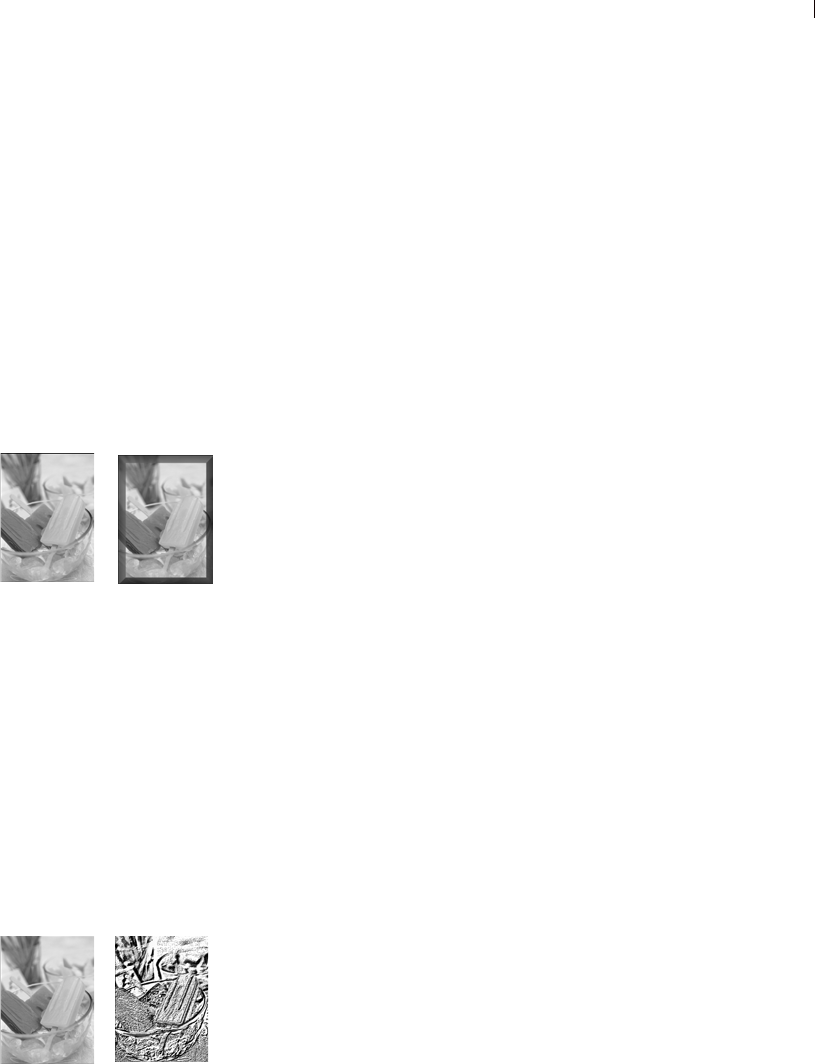
Chapter 9: Applying Effects 221
To reset settings to default values, in the Presets drop-list select
Reset to Default.
When you first open a dialog, Paint Shop Pro displays the last-
used settings. (The Presets drop-list is set to Last Used.) Use this
preset to apply the same effect to multiple images without having
to adjust the settings each time.
To save and load your own preset effects, see “Using and
Creating Presets” on page 420.
Applying 3D Effects
The 3D effects create images or selections that appear to have three
dimensions. These effects are particularly useful for creating images
for Web pages. To see the appropriate effect for the Buttonize,
Chisel, Cutout, Drop Shadow, Inner Bevel, and Outer Bevel effects,
first make a selection in the image.
To apply an effect, choose it from the Effects Browser or choose
Effects > 3D Effects and select an effect.
To apply these effects to an entire layer, increase the canvas size to
add pixels around the edges.
Note
These effects work on greyscale and 16 million color (24-bit)
images only. To increase the color depth of an image, see
page 261.
For descriptions and visual examples of each effect, refer to the
Help system.
Applying Art Media Effects
Apply art media effects to make an image look like it was painted or
drawn using pencil, charcoal, or chalk. To limit an effect to a
specific area, make a selection before applying the effect.
To apply an effect, choose it from the Effects Browser or choose
Effects > Art Media Effects and select an effect.
Note
These effects work on greyscale and 16 million color (24-bit)
images only. To increase the color depth of an image, see
page 261.
For descriptions and visual examples of each effect, refer to the
Help system.
Example of a 3D effect
Example of an Art Media effect
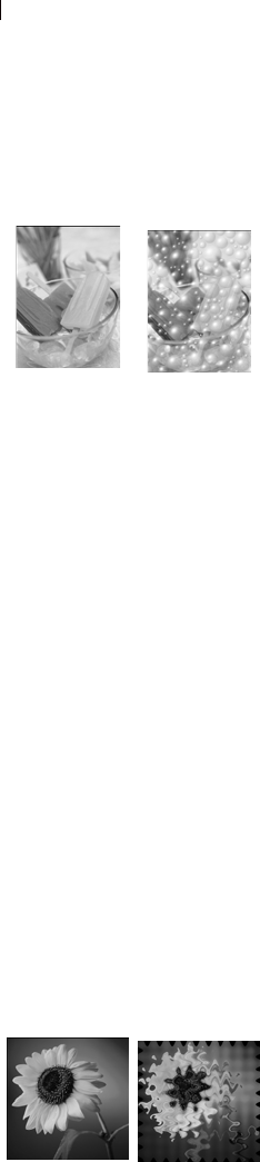
Chapter 9: Applying Effects
222
Applying Artistic Effects
Apply artistic effects to age a photograph or to create a variety of
artistic results. To limit an effect to a specific area, make a selection
before applying the effect.
To apply an effect, choose it from the Effects Browser or choose
Effects > Artistic Effects and select an effect.
Note
These effects work on greyscale and 16 million color (24-bit)
images only. To increase the color depth of an image, see
page 261.
For descriptions and visual examples of each effect, refer to the
Help system.
Applying Edge Effects
Use Edge effects to clarify your image and to accentuate the edges
and contrast areas in your image.
To apply an effect, choose it from the Effects Browser or choose
Effects > Edge Effects and select an effect.
Note
These effects work on greyscale and 16 million color (24-bit)
images only. To increase the color depth of an image, see
page 261.
For descriptions and visual examples of each effect, refer to the
Help system.
Applying Distortion Effects
Apply distortion effects to distort an image. To limit an effect to a
specific area, make a selection before applying the effect.
To apply an effect, choose it from the Effects Browser or choose
Effects > Distortion Effects and select an effect.
Note
These effects work on greyscale and 16 million color (24-bit)
images only. To increase the color depth of an image, see
page 261.
For descriptions and visual examples of each effect, refer to the
Help system.
Example of an Artistic effect
Example of an Distortion effect
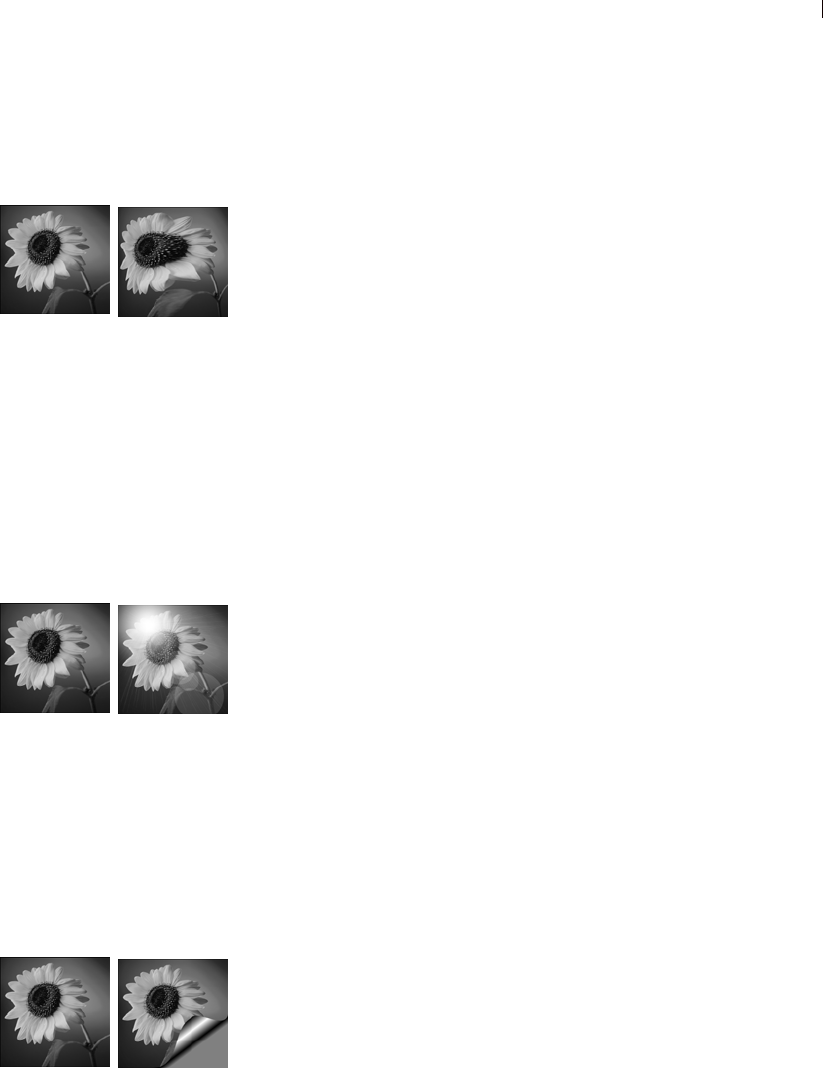
Chapter 9: Applying Effects 223
Applying Geometric Effects
The geometric effects include such effects as turning an image into a
sphere or cylinder, and altering an image’s perspective. To limit an
effect to a specific area, make a selection before applying the effect.
To apply an effect, choose it from the Effects Browser, or choose
Effects > Geometric Effects and select an effect.
Note
These effects work on greyscale and 16 million color (24-bit)
images only. To increase the color depth of an image, see
page 261.
For descriptions and visual examples of each effect, refer to the
Help system.
Applying Illumination Effects
The illumination effects apply a sunburst or spotlights to images. To
limit an effect to a specific area, make a selection before applying
the effect.
To apply an effect, choose it from the Effects Browser, or choose
Effects > Illumination Effects and select an effect.
Note
These effects work on greyscale and 16 million color (24-bit)
images only. To increase the color depth of an image, see
page 261.
For descriptions and visual examples of each effect, refer to the
Help system.
Applying Image Effects
The Image effects are Offset, Page Curl, and Seamless Tiling. To
limit an effect to a specific area, make a selection before applying
the effect.
To apply an effect, choose it from the Effects Browser, or choose
Effects > Image Effects and select an effect.
Note
These effects work on greyscale and 16 million color (24-bit)
images only. To increase the color depth of an image, see
page 261.
Example of a Geometric effect
Example of an Illumination
effect
Example of an Image effect
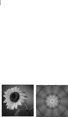
Chapter 9: Applying Effects
224
For descriptions and visual examples of each effect, refer to the
Help system.
Applying Reflection Effects
The reflection effects include such effects as creating a kaleidoscope
or an intricate pattern. To limit an effect to a specific area, make a
selection before applying the effect.
To apply an effect, choose it from the Effects Browser, or choose
Effects > Reflection Effects and select an effect.
Note
These effects work on greyscale and 16 million color (24-bit)
images only. To increase the color depth of an image, see
page 261.
For descriptions and visual examples of each effect, refer to the
Help system.
Example of a Reflection effect
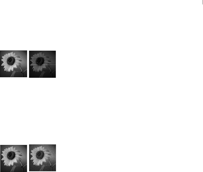
Chapter 9: Applying Effects 225
Applying Texture Effects
The texture effects turn images into a variety of textures, such as
leather, mosaic tiles, and polished stone. To limit an effect to a
specific area, make a selection before applying the effect.
To apply an effect, choose it from the Effects Browser, or choose
Effects > Texture Effects and select an effect.
Note
These effects work on greyscale and 16 million color (24-bit)
images only. To increase the color depth of an image, see
page 261.
For descriptions and visual examples of each effect, refer to the
Help system.
Adding Noise
Use the Add Noise effect to reduce the detail in an image and add a
grainy texture. This effect can also be used for image correction. By
adding a small percentage of noise to an image, you can reduce the
appearance of small imperfections and scratches.
To use the Add Noise effect:
1 Choose Adjust > Add/ Remove Noise > Add Noise to open the Add
Noise dialog.
2 Choose the pattern of the noise: Random, Uniform, or Gaussian.
With Uniform noise, the color of the noise resembles the original
pixels. With Gaussian noise, the majority of the noise values are
even closer to the original.
3 In the Add Noise edit box, select the percentage of noise to add.
4 To use black and white noise pixels, mark the Monochrome check
box. To use colored pixels, clear the check box.
5 Click OK.
Example of a Texture effect
Adding noise to an image

Chapter 9: Applying Effects
226
Adding Picture Frames
Picture frames can provide an eye-catching final touch to your
images. Choose from square or oval frames, modern or classic
styles, stained glass or metal, or a variety of other styles. The frame
is applied on a separate layer. After adding the picture frame you can
edit it like any layer— move it with the Move tool, turn its visibility
on and off, change its opacity, color, etc.
Note
This effect works on greyscale and 16 million color (24-bit)
images only. To increase the color depth of an image, see
page 261.
To add a picture frame:
1 Choose Image > Picture Frame to open the Picture Frame dialog.
2 In the Picture Frame section of the dialog, select a frame from the
drop-list.
3 If the frame has transparent areas (for example, round or oval
frames), in the Transparency color section of the dialog choose
your options:
To have the transparent areas remain transparent, mark the
Keep Transparent check box.
To use a color for transparency areas, clear the Keep
Transparent check box and click the color box to select a
color.
Adding a picture frame

Chapter 9: Applying Effects 227
4 In the Orientation section of the dialog, select the frame
placement: Frame inside of the image or Frame outside of the
image.
If you select an inside frame, Paint Shop Pro resizes the frame
to fit within the image canvas.
If you select an outside frame, Paint Shop Pro increases the
canvas size to accommodate the frame. The added canvas uses
the current background color. However, the area will be
transparent if it is a layer and you mark the Keep Transparent
check box.
5 Choose other options in the Orientation section of the dialog:
Frame canvas When this layer option is chosen, the frame will
reside on a layer named "Picture Frame" in the Layers palette.
If you apply successive frames using this option, the frames
will reside on layers named "Picture Frame 1," "Picture Frame
2," etc.
Frame current layer When this layer option is chosen, the
frame will reside on a layer with the same name as the original
except with the words "Picture Frame" appended to it. For
example, if you append a frame to the Background layer, the
frame will reside on a layer named "Background Picture
Frame." If you apply successive frames using this option, the
frames will reside on layers named after the original but
appended with "Picture Frame 1," "Picture Frame 2," etc.
Flip frame Reverses the frame along its horizontal axis.
Mirror frame Reverses the frame along its vertical axis.
Rotate frame 90 CW Rotates the frame clockwise.
6 Click OK. Paint Shop Pro adds the frame to the image and creates
a new layer based on whether you selected Frame canvas or
Frame current layer (described above).
Note: If the width and height differ by a considerable amount, the
frame appears thicker along the shorter sides.
Note: After you add a picture frame, you can edit it as you can
any layer—move it with the Move tool, turns its visibility on and
off, or change its opacity, color, etc.
Picture frames with
transparency
If you apply a picture frame with
transparent areas to a background
layer and place the frame outside
the image, the transparent areas
are the current background color
rather than transparent. (The
background layer does not support
transparency.)
Loading picture frames
To change the folder to load picture
frames from, click the File
Locations button. By default,
picture frames are stored in the
Frames folder of the Paint Shop
Pro program folder.

Chapter 9: Applying Effects
228
Creating Your Own Effects
To create your own effects (also called filters), use the User Defined
command.
To create your own effects:
1 Choose Effects > User Defined to open the User Defined Filter
dialog.
The edit boxes in the Filter matrix group box show coefficients
that process pixels to create the effect.
2 In the Presets drop-down list, select a filter to use as a starting
point. Choose Default for default settings or select one of the
other filters.
3 Set the Matrix modifiers:
The Divisor number is used to divide the Filter matrix values.
It can reduce the effects of the filter matrix. Use the Compute
button to calculate a Divisor that will adjust the brightness of
the image back to no change.
The Bias number shifts each color value by a fixed amount.
The number is added to the color value produced by the filter
matrix.
4 In the Apply to group box, pick the which color values the effect
applies to.Choose Color Channels and mark the channels, or
choose Grey Values.
5 After you make changes, click OK. Paint Shop Pro applies the
effect to the image.
Using the Displacement Map Effect
This filter allows the user to warp, or displace, one image based on
the contents of another image. This can allow you to do such things
as:
Apply text to real world objects to make it look like the text was
there all along;
Create your own unique deformation type effects based on
images previously modified by Paint Shop Pro's Distortion or
Geometric effects;
By using the dialog's Gradient option, users can create effects
resembling morphing-type effects such as erosion and dilation;
An easy way to create your
own effects
On the User Defined Filter dialog,
click the Randomize button to
automatically adjust the
coefficients and create unusual
effects. Just keep clicking the
Randomize button until you find an
effect that you like.

Chapter 9: Applying Effects 229
By combining images such as gradients with line art this filter
can produce interesting embossing type effects;
Accessing and Using the Filter
1 Choose Effects > Distortion Effects > Displacement Map.
2 In the Displacement Map section of the dialog, click the image
drop-list and choose an image to use as the displacement map.
3 Because the map likely won't have the same dimensions as the
source image being transformed, choose either the Stretch map
to fit image option, or the Tile map to cover image option. If you
choose the Tile option, you can adjust the Size % setting to tile
the image to a size that covers the image being deformed.
4 Set the Blur value to the amount you wish to blur the
displacement map. Lower values produce jittery, pointillist
effects, while higher values produce smoother warping effects.
5 In the Displacement Properties section, choose one of these
options:
2D offsets using red and green: this option displaces the image
using the red and green channels.
3D surface using luminance: this option displaces pixels in
proportion to changes in light. Like a bump map, this option
treats the source image like it's a 3D surface in which pixel
luminance values determine height.
6 Use the Intensity setting to control the amount of displacement.
Lower values result in less change to the image, higher values
yield greater deformation.
7 Use the Rotation setting to determine the rotation of the
displacement data. For example, a setting of 180 changes
upward/left displacement to downward/right displacement.
8 Use the Edge mode setting to determine how "out of bounds"
displacement is handled:
Wrap: treats the image as if it were a tile repeating in each
direction.
Repeat: takes each side's edge pixel and repeats it outward
infinitely.
Color: allows you to choose a color from the Color box to
represent out of bounds pixels.

Chapter 9: Applying Effects
230
Transparent: (available only with layered images) results in out
of bounds pixels being transparent.
Using the Radial Blur Effect
This filter produces an image effect that simulates what you might
see if you took a picture while spinning a camera in circles, or by
zooming in quickly using a very slow shutter speed. You can also
choose a twirling effect.
Accessing and Using the Filter
1 Choose Adjust > Blur > Radial Blur.
2 In the Blur type section, choose one of these options:
Spin: blurs pixels circularly around the image center.
Zoom: blurs pixels away from the center.
Twirl: blurs pixels in a spiraling manner.
3 In the Blur section, choose a Strength value. Lower values lessen
the effect; higher values intensify the effect.
4 If you chose the Twirl option, you can then set the Twirl degrees
value, which ranges from -90 to 90.
5 Mark the Elliptical check box if the radius should be squeezed to
fit the image. If the image is square, this option will have no
effect. For rectangular images, this option produces elliptical
blurring; when turned off, the blurring will be circular.
6 In the Center section, choose the settings that affect the center of
the image:
Horizontal offset %: allows you to set the horizontal center point
of the blur.
Vertical offset %: allows you to set the vertical center point of the
blur.
Protect center %: allows you to determine how much to diminish
blurring at the image center. Higher values increase the radius of
the unblurred center area.

Chapter 9: Applying Effects 231
Mathematically Combining Two Images
Paint Shop Pro can create a variety of effects using the Arithmetic
effect, which combines two images to produce a third one based on
settings you select.
To combine images using the Arithmetic command:
1 Open the two images you want to combine.
2 Choose Image > Arithmetic to open the Image Arithmetic dialog.
3 In the Image #1 and Image #2 drop-down lists, select the images
to combine. The size of Image #1 determines the size of the new
image.
4 In the Function group box, select a method for combining the
images. The color data from the two images is combined on a
pixel-by-pixel basis according to the function.
5 From the Channel group box, select the color channels to
combine:
Mark the All channels check box to use all the color channels
in both images. This will produce a 24-bit image.
Select a specific color channel for each image to produce a
greyscale image.
Function New Color Value Equals
Add Image 1 Value + Image 2 Value
Subtract Image 1 Value - Image 2 Value
Multiply Image 1 Value x Image 2 Value
Difference Absolute Value of (Image 1 Value - Image 2
Value)
Lightest Maximum of (Image 1 Value, Image 2 Value)
Darkest Minimum of (Image 1 Value, Image 2
Value)
Average (Image 1 value + Image 2 Value) / 2
Or Binary Or
And Binary And

Chapter 9: Applying Effects
232
6 Set the Modifiers. The modifiers are applied to the color values
produced by the Formula and the Channel selections.
The Divisor number is used to divide the color values. It can
reduce the effects of the other selections.
The Bias number shifts each color value by a fixed amount.
The number is added to the color value produced by the
Formula, Channel, and Divisor selections.
7 Mark or clear the Clip color values check box to determine how
Paint Shop Pro handles final color values greater than 255 and
less than 0.
8 Click OK.
Check box
Setting If value is less
than 0 If Value is more
than 0
Selected value = 0 value = 255
Cleared value = 256 + value value = value - 256

233
Working with Colors and Materials
Whether you are applying color to an image or adjusting
photographic colors, it’s important to understand how Paint Shop
Pro works with color. This chapter describes how to choose colors
and materials that you can use to paint, draw, or fill. It also discusses
the basics of color—how it is displayed on screen and printed—as
well as image color depth.
Contents Basics of Using the Materials Palette . . . . . . . . . . . . . . . . . . . . 234
Using the Materials Palette . . . . . . . . . . . . . . . . . . . . . . . . . . . 236
Choosing Colors . . . . . . . . . . . . . . . . . . . . . . . . . . . . . . . . . . . 239
Choosing Gradients. . . . . . . . . . . . . . . . . . . . . . . . . . . . . . . . . 244
Choosing Patterns. . . . . . . . . . . . . . . . . . . . . . . . . . . . . . . . . . 246
Choosing Textures . . . . . . . . . . . . . . . . . . . . . . . . . . . . . . . . . 247
Working with Swatches . . . . . . . . . . . . . . . . . . . . . . . . . . . . . . 249
Editing Gradients. . . . . . . . . . . . . . . . . . . . . . . . . . . . . . . . . . . 251
Understanding Color and Color Models. . . . . . . . . . . . . . . . . . . 256
How Monitor and Print Colors Differ . . . . . . . . . . . . . . . . . . . . . 258
Working with Color Channels . . . . . . . . . . . . . . . . . . . . . . . . . . 259
Understanding Color Depth . . . . . . . . . . . . . . . . . . . . . . . . . . . 260
Working with Image Palettes . . . . . . . . . . . . . . . . . . . . . . . . . . 269
Making a Palette Color Transparent . . . . . . . . . . . . . . . . . . . . . 272
CHAPTER 10
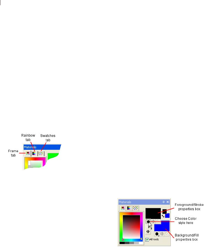
Chapter 10: Working with Colors and Materials
234
Basics of Using the Materials Palette
The Materials palette offers a variety of ways to choose colors,
styles, and materials for the raster and vector tools. When using the
Art Media tools, however, you'll notice some functionality of the
Materials palette is disabled.
To display or hide the Materials palette:
Choose View > Materials palette or press F6. To close the palette you
can click the Close button located in the palette's title bar, or choose
View > Palettes > Materials again.
To choose a foreground or background solid color:
1 On the Materials palette, make sure the Foreground or Background
style is set to Color (not Gradient or Pattern), and the either the
Frame or Rainbow tab is active, then do one of the following:
To choose a foreground color, click the Foreground/Stroke
properties box. This will display the Material Properties
dialog.
To choose a background color, click the Background/Fill
properties box. This will display the Material Properties
dialog.
Note: You can also click the Foreground Material box or the
Background Material box to display the Material Properties
dialog, and then click the Color tab.
2 From the Material Properties dialog's Color tab, select the desired
color, and then click OK.
Materials palette tabs
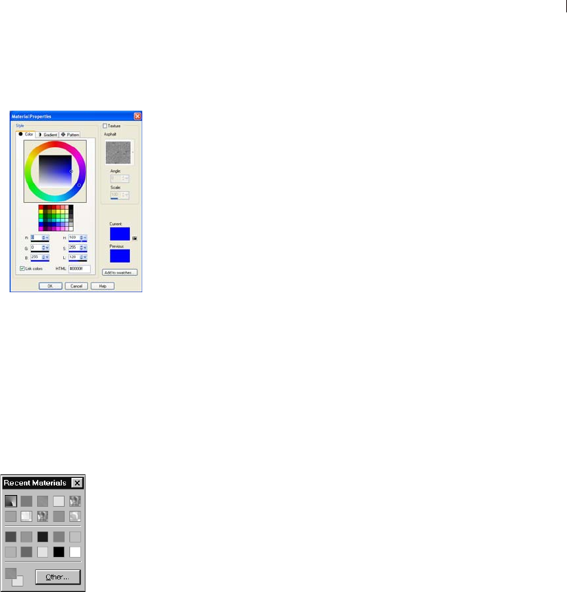
Chapter 10: Working with Colors and Materials 235
To choose a foreground or background material (color, gradient,
pattern, or texture):
1 On the Materials palette, do one of the following:
To choose a foreground material, click the
Foreground Material box.
To choose a background material, click the
Background Material box.
The Material Properties dialog opens. In this dialog, you can
choose from all of Paint Shop Pro’s colors, gradients, patterns,
and textures.
2 To choose the style, click the Color, Gradient, or Pattern tab and
select the appropriate settings. For more information, see
“Choosing Colors” on page 239, “Choosing Gradients” on
page 244, or “Choosing Patterns” on page 246.
3 To choose a texture, mark the Texture check box and select a
texture. For more information, see “Choosing Textures” on
page 247.
4 Click OK.
To choose from recently used materials:
On the Materials palette, right-click a Color or Material box to
display the Recent Materials dialog, and then choose a material.
On the Recent Materials dialog you can click the Other button to
display the Material Properties dialog and choose or create a
material from all of Paint Shop Pro’s colors, gradients, patterns, and
textures.
To choose a color from the Frame tab:
1 On the Materials palette, click the Frame tab . It displays an outer
Hue rectangle and an inner Saturation rectangle, as well as a strip
containing white, three shades of grey, and black.
2 On the Saturation rectangle, click on the desired saturation:
Left-click to set the Foreground/Stroke color (hold down the
mouse button to display a tool tip with the cursor position's
RGB value)
Right-click to set the Background/Fill color (hold down the
mouse button to display a tool tip with the cursor position's
RGB value)
3 Drag the horizontal slider to further adjust the saturation.
The Material Properties dialog
Recent Materials dialog
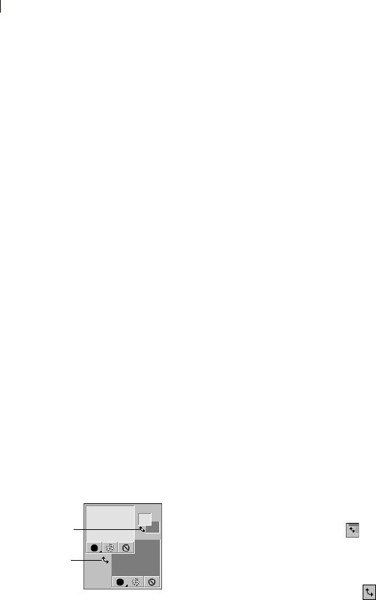
Chapter 10: Working with Colors and Materials
236
4 Drag the vertical slider to adjust lightness.
To choose a color from the Rainbow tab's Available Colors
panel:
1 On the Materials palette, click the Rainbow tab .
2 Move the cursor over the Available Colors panel; its shape
changes to a dropper. As you move the dropper around the panel,
a ToolTip displays the color value beneath the dropper tip.
3 Do one of the following:
To choose the foreground color, left-click in the Available
Colors panel.
To choose the background color, right-click in the Available
Colors panel.
The Foreground or Background Color box displays the selected
color. If the Style button is set to Gradient or Pattern, change it to
Color so that the material is updated with the color.
To apply the current materials to all tools:
On the Materials palette, mark the All tools check box.
If you clear this check box, the current materials are applied to the
active tool only.
To reverse the foreground and background colors:
Click the Swap Colors icon .
To reverse the foreground and background materials:
Click the Swap Materials icon .
Using the Materials Palette
With Paint Shop Pro you can paint, draw, and fill with a variety of
colors, styles, and materials. A style is the color, gradient, or pattern.
A material is the style plus the optional texture. You select materials
on the Materials palette.
You can reverse the foreground
and background color or
material
S
wap Materials
Swap Colors
Color basics
For information on color—how it is
perceived, displayed, and printed—
see “Understanding Color and
Color Models” on page 256.
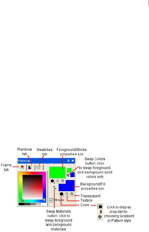
Chapter 10: Working with Colors and Materials 237
In general you use foreground materials for brush strokes and
background materials for fills. When you paint with a raster brush,
right-clicking the brush paints with the background material, and for
fill tools, left-clicking fills with the foreground material. When using
the Art Media tools, the current foreground color is used to apply
pigment in the Mixer palette. For text and vector shapes, the
foreground color is the stroke (or outline) of the text or shape and the
background color is the fill of the text or shape.
In general, it's best to select the tool you want to use, select the
color/material on the Materials palette, set the other tool options, and
then use the tool.
Note that when using the Art Media tools, some functionality of the
Materials palette is disabled.
The Materials palette is shown below.
Here are the main components of the Materials palette:
Frame tab This is the first tab across the top. It displays an outer Hue
rectangle and an inner Saturation rectangle, as well as a strip
containing white, three shades of grey, and black. You can drag the
vertical slider to adjust lightness, and drag the horizontal slider to
adjust saturation.
Rainbow tab This is the second tab across the top. It displays the
Available Colors panel, where you can click to select a color. At the
bottom of the tab you can click to select white, black, or three shades
of grey.
Swatches tab Displays swatches, which are materials you can save
to use again. For more information, see “Working with Swatches” on
page 249.
Foreground and Background Color boxes Display the current
foreground or background color.
About the relationship
between the Material and
Color boxes
Since you can select colors by
clicking the Material boxes, you
may wonder why the Materials
palette includes Color boxes too.
With the Foreground or
Background Property box, you can
select a new color even when the
Material box displays a gradient or
a pattern. The Color boxes provide
a quick way to change colors
without changing the other parts of
the material.
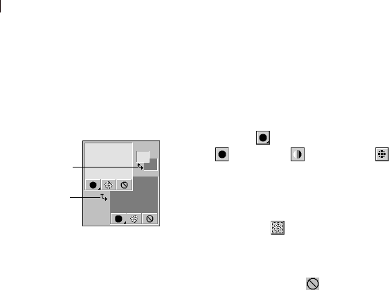
Chapter 10: Working with Colors and Materials
238
Foreground and Background Material boxes Display the current
foreground or background material (the style—color, gradient, or
pattern—plus the texture).
Style button Specifies which style is currently selected:
color , gradient , or pattern . To change between the most
recently selected color, gradient, or pattern: click the Style button
and select a new style. To define a new color, gradient, or pattern,
click a Material box.
Texture button Turns the current texture on or off. To choose a
new texture, click the Foreground Material or Background Material
boxes.
Transparency button Specifies whether the foreground or
background material is transparent (in other words, it has no style or
texture). You use a transparent material primarily with vector objects
and text—a transparent foreground has no outline (the objects or
letters are filled only) and a transparent background has no fill (the
objects or letters are outlined only). This button is unavailable for
tools that require a foreground or background color.
All Tools If the check box is marked, the selected foreground and
background materials apply to all tools. If the check box is cleared,
the selected materials apply only to the active tool (such as the
Paintbrush tool or the Preset Shapes tool).
Note
The All Tools check box does not apply to the Edit Text command.
You can reverse the foreground
and background color or
material
S
wap Materials
Swap Colors
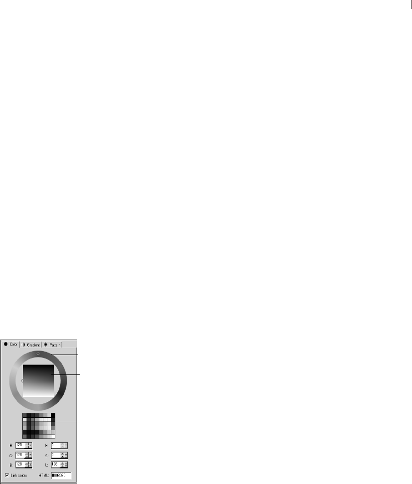
Chapter 10: Working with Colors and Materials 239
Choosing Colors
When you edit images in Paint Shop Pro, you often need to choose a
color—before you paint, when making manual color corrections, or
when choosing a background for a new image. You choose colors as
follows:
For images with 16 million colors, choose from the Jasc Color
Picker. See “Choosing Colors from the Jasc Color Picker” on
page 239.
With images with 2 to 256 colors, choose from the image palette.
See “Choosing Colors from the Image Palette” on page 242.
For all images, you can choose a color from an open image or
from any displayed color. See “Choosing Colors from an Image
or the Desktop” on page 242.
Choose a color from the Frame tab or the Rainbow tab of the
Materials palette. Left-click to choose the foreground color or
right-click to choose the background color.
Choosing Colors from the Jasc Color Picker
The Jasc Color Picker displays when you click a Color or Material
box on the Materials palette. You also choose from this color picker
when you click a Color box in some Paint Shop Pro dialogs.
The Jasc Color Picker offers a variety of ways to select colors:
Select from the Color wheel and Saturation/Lightness box, which
offer a visual way to select a color based on its hue, saturation,
and lightness.
Select from the Basic Colors panel, which displays commonly
used colors.
Select RGB or HSL values to choose a color based on its red,
green, and blue values or its hue, saturation, and lightness values.
Enter an HTML color code.
Select a color from the active image.
Note
If the active image has a color depth less than 24-bit (16 million
colors), you must select colors from a palette rather than the Jasc
Color Picker. See “Choosing Colors from the Image Palette” on
page 242.
The Jasc Color Picker
Color whee
l
Saturation/
Lightness
box
Basic Colors
panel
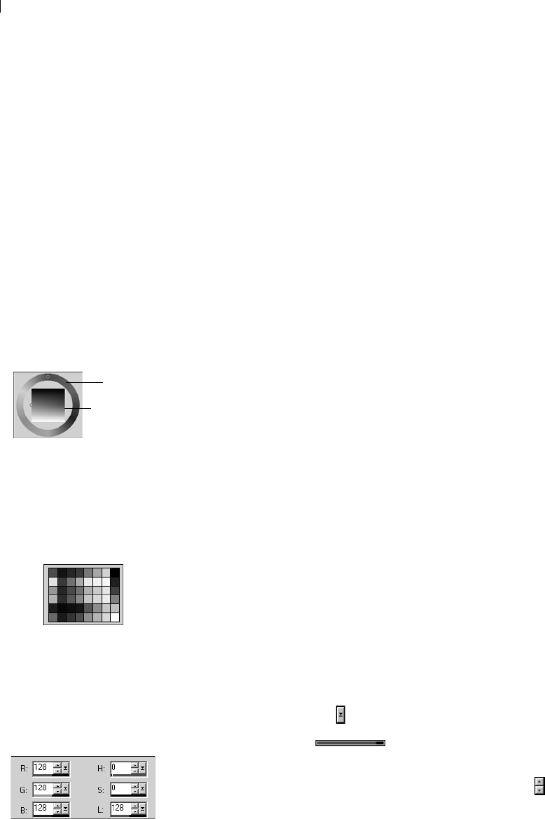
Chapter 10: Working with Colors and Materials
240
To display the Jasc Color Picker:
On the Materials palette, do one of the following:
To choose the foreground color, click the Foreground Material
box or Foreground Color box.
To choose the background color, click the Background Material
box or Background Color box.
If you clicked a Material box, the Material Properties dialog opens
(here you can choose colors, gradients, patterns, and textures); click
the Color tab to display the Jasc Color Picker.
If you clicked a Color box, the Color dialog opens and displays the
Jasc Color Picker; here you can choose colors only.
To choose a color using the Color wheel:
1 On the Color wheel, click the approximate color or drag the
selection ring around the color wheel to select the color.
The Color wheel represents the hue—notice that the Hue edit box
updates with a value between 0 and 255 as you go around the
wheel.
2 On the Saturation/Lightness box, click to choose a color variation
or drag the selection ring. Move from left to right to increase the
saturation. Move from top to bottom to increase the lightness.
To choose a color from the Basic Colors panel:
1 Move the cursor over the Basic Colors panel. A ToolTip displays
the color value.
2 Click the color you want. Notice that the RGB and HSL values
update with the current color values and the selection rings on
the Color wheel and the Saturation/Lightness box move to the
selected color.
To choose a color using its RGB or HSL value:
For each value you want to change, do one of the following:
Click the slider button and drag the slider to a new position.
Drag the meter bar to a new position.
Click the edit box and type a new value.
To change the value by one, click the up or down arrows .
The selection rings show which
color is selected
Color wheel
Saturation/
Lightness
box
The Basic Colors panel displays
commonly used colors
Use the numeric edit controls to
choose a color using its
RGB or HSL value

Chapter 10: Working with Colors and Materials 241
Note: Clear the Link Colors check box to have the sliders visually
represent only their selected value (such as just the hue).
To choose a color from the active image:
1 Make sure the Jasc Color Picker is displayed. See “To display the
Jasc Color Picker:” on page 240.
2 Move the cursor over the active image. The cursor turns into a
dropper and a ToolTip displays the color values.
3 Click the part of the image that has the color you want. The Jasc
Color Picker updates with that color.
Note: You can also choose a color from an image using the
Dropper tool or a special feature of Color or Material boxes. See
“Choosing Colors from an Image or the Desktop” on page 242.
Specifying HTML Code for Colors
With the Jasc Color Picker, you can view the HTML (Hypertext
Markup Language) code for each color you select. You can also
specify a color by entering the HTML code.
Note
By default, Paint Shop Pro displays decimal (base 10) numbers in
the Jasc Color Picker. You can also display hexadecimal (base 16)
numbers—the format of HTML color codes. For more information,
see “Display and Caching Preferences” on page 61.
To specify or view HTML code for colors:
1 Display the Jasc Color Picker. See “To display the Jasc Color
Picker:” on page 240.
2 Do one of the following:
To specify a color using its HTML code, type the code in the
HTML edit box.
To view the HTML code of a particular color, choose a color
by other methods (such as entering RGB values or selecting
from the color wheel), and then view the number in HTML
edit box.
The HTML code for the color
true red (RGB 255, 0, 0) in the
Jasc Color Picker
Red
Green
Blue
Hexadecimal symbol
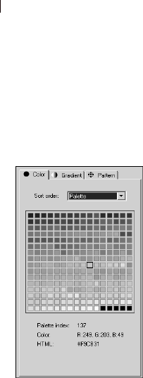
Chapter 10: Working with Colors and Materials
242
Choosing Colors from the Image Palette
Images that have a color depth less than 24-bit (16 million colors)
are called paletted images—the available colors are a subset of all
the colors your computer can display. The palette varies from 2 to
256 colors, depending upon the color depth of your image. With
these images, you must choose foreground and background colors
from the palette rather than from the Jasc Color Picker.
Note
If you select the Rainbow Picker as your preference setting, the
Available Colors panel of the Materials palette shows all colors for
both paletted and non-paletted (16 million color) images. For
paletted images, when you select a color on the Available Colors
panel Paint Shop Pro chooses the nearest color in the palette.
To choose colors from the palette:
1 On the Materials palette, do one of the following:
To choose the foreground color, click the Foreground Color or
Foreground Material box.
To choose the background color, click the Background Color
or Background Material box.
Clicking a Color box opens the Color dialog and displays the
palette. Clicking a Material box opens the Material Properties
dialog; click the Color tab to display the palette.
2 In the Sort order drop-down list, select the way the colors are
sorted: Palette (in order by the way the palette stores the colors),
Hue (in order by color) or Luminance (in order by lightness).
3 Click the desired color. The color’s index number within the
palette, color value (RGB or HSL), and HTML code are
displayed.
4 Click OK.
Choosing Colors from an Image or the Desktop
Use the Dropper tool to choose a foreground or background color
from any open image. Or use a special feature of Color and Material
boxes to select from any color within Paint Shop Pro (such as a color
on a toolbar). If you have Windows 2000 or later, you can choose a
color from other applications (such as a color displayed in a word
processor).
Selecting colors from the
image palette
When should I choose a
color from the desktop?
You can choose a foreground or
background color from the desktop
when you particularly like an icon
color, or when you want to match
the Windows desktop colors.
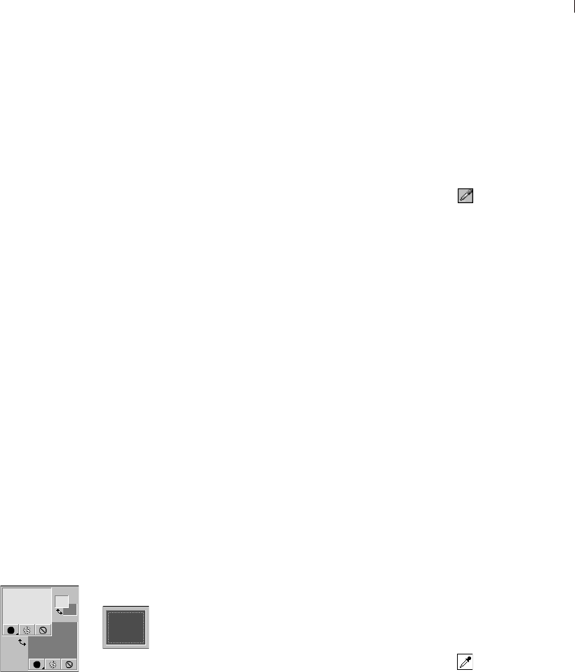
Chapter 10: Working with Colors and Materials 243
Note
You can also use the Jasc Color Picker to choose a color from any
open image. See “To choose a color from the active image:” on
page 241.
To use the Dropper tool to choose (or sample) a color:
1 On the Tools toolbar, choose the Dropper tool . The tool may be
hidden under the Color Replacer tool.
2 Position the cursor over the color in the image.
3 Left-click to make the color the foreground color or right-click to
make it the background color.
To choose a color from the active image:
1 Position the cursor over the active image.
Note: This applies to the Brush, Eraser, and Picture Tube tools.
2 Hold down the Ctrl key and left-click to choose the color as the
foreground color or right-click to choose the color as the
background color.
To choose a color from an image or the desktop:
1 Make sure the color you want to choose is displayed on the screen.
2 Position the cursor over a Color or Material box (on the Materials
palette or in a dialog).
Note: On the Materials palette, you must assign the foreground
and background color separately. Position the cursor over one or
the other, follow the steps, and then start over for the other color.
3 Hold down the Ctrl key and continue to hold it down until you’ve
completed the following steps.
4 Move the cursor over the area of the desktop that has the color
you want to choose. The cursor is a dropper over any area
that you can choose from. For Windows 2000 or later systems,
the cursor remains a dropper when you move off Paint Shop Pro
onto another application.
5 Left-click to select the color. The Color box or Material box
updates with the color.
6 To change the color selection, continue to hold the Ctrl key and
click on different parts of the desktop.
7 Release the Ctrl key.
Material and Color boxes on the
Materials palette (left) and a
Color box on a Paint Shop Pro
dialog (right).
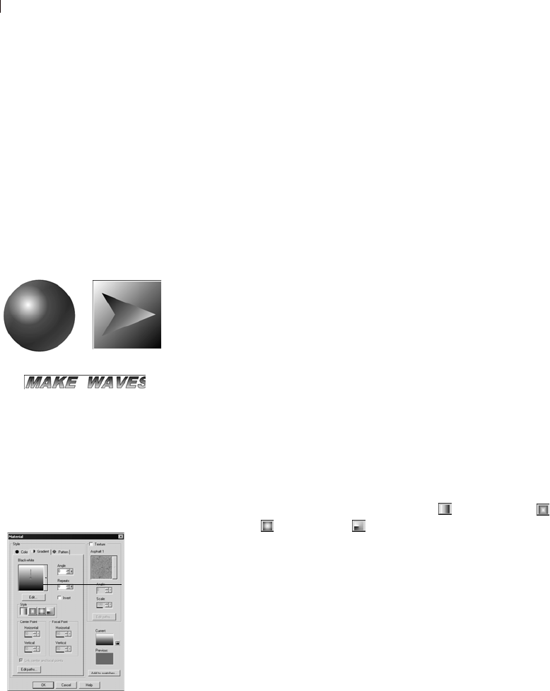
Chapter 10: Working with Colors and Materials
244
Choosing Gradients
Gradients are gradual blends between two or more colors. You can
paint, draw, or fill with gradients to create interesting effects or
helpful color transitions. Use gradients to create Web buttons with
shadows and highlights, to make objects look shiny or glowing, or to
add dimension to objects. Use gradients to fade Web page graphics
into other content or use a black-to-white gradient as a mask.
You choose gradients on the Gradient tab of the Material Properties
dialog.
To choose a foreground or background gradient:
1 On the Materials palette, set the Foreground/Stroke or the
Background/Fill style to Gradient, and then click the associated
property box. This displays the Materials Properties dialog, and the
Gradient tab will be active.
2 Click the Gradient drop-list to view a thumbnail of the available
gradients. If necessary, choose a Category containing the desired
gradients.
3 Click the desired gradient. This closes the drop-list. The gradient
name will appear above the drop-list.
4 If desired, set the following options for the gradient:
Style The style for the gradient: Linear , Rectangular ,
Sunburst , and Radial .
Angle (Linear, rectangular, and radial gradients only) The angle
or direction of the gradient, from 0 to 359 degrees.
Repeats The number of times (from 0 to 100) to repeat the
gradient pattern.
Invert Mark to invert the colors of the gradient.
Center Point (Rectangular, sunburst, and radial gradients only)
The horizontal and vertical coordinates of the point from which
the gradient disperses or radiates. The distance is measured as a
percentage of the fill area’s width. Change the center point to
create fills in circles or other shapes where the center of the
gradient is not at the center of the object.
Color depth
Gradients are available for
greyscale and 16 million color
images only. To increase the color
depth of an image, see page 261.
Example applications of
gradients
The Gradient tab of the
Material Properties dialog
Gradient
drop-list
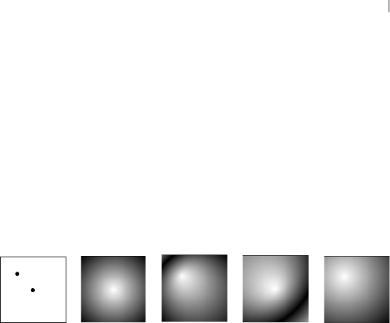
Chapter 10: Working with Colors and Materials 245
Focal Point (Rectangular and sunburst gradients only) The
horizontal and vertical coordinates of the point where the
foreground color of the gradient begins. The distance is measured
as a percentage of the fill area’s width. Change the focal point to
create fills in circles or other shapes where the effective light
source is not at the center of the object. This option is available
only when the Link Center and Focal Points check box is cleared.
The examples below show the effect of varying the center point
and the focal point.
Link center and focal points (Rectangular and sunburst
gradients) Mark this check box to have the center and focal
points be the same values. Clear the check box to edit the focal
point separately from the center point.
Note: You can also move the center point by dragging the control
needle or cross-hairs shown in the Gradient drop-list. If you clear
the Link Center and Focal Points check box, you can move the
focal point by dragging the cross-hairs on the gradient.
5 To edit the colors, transition points, and opacity of the gradient,
click the Edit button. For more information, see “Editing
Gradients” on page 251.
6 To save this gradient as a swatch that you can access later, click
the Add to swatches button, type a name, and press Enter.
7 Click OK.
Location of
coordinates
30, 30
50, 50
C
enter: 50, 50
F
ocal: 50, 50
C
enter: 50, 50
F
ocal: 30, 30
C
enter: 30, 30
F
ocal: 50, 50
C
enter: 30, 30
F
ocal: 30, 30
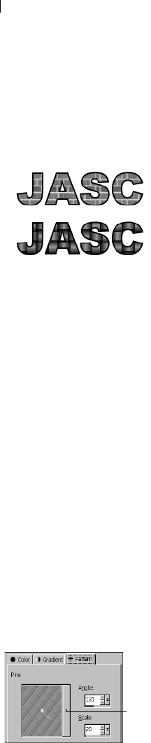
Chapter 10: Working with Colors and Materials
246
Choosing Patterns
You can paint, draw, or fill patterns to create interesting effects.
Paint Shop Pro includes many patterns (such as bricks and zebra
stripes). You can create your own as well. You can also use an entire
image or part of an image as a pattern.
Patterns are a great way to add creative flair to your images. You can
apply patterned brushstrokes, create objects with patterned fills or
edges, and create patterned text. You can use patterns to create
stationary to use when sending e-mail or to create tiled images for
Web pages. Patterns are especially helpful for projects that require
an interesting background—such as a CD covers, calendars, or
greeting cards.
You choose patterns on the Patterns tab of the Material Properties
dialog.
To choose a foreground or background pattern:
1 On the Materials palette, set the Foreground/Stroke or the
Background/Fill style to Pattern, and then click the associated
property box. This displays the Materials Properties dialog, and the
Pattern tab will be active.
2 Click the Pattern drop-list to view a thumbnail of the available
patterns. If necessary, choose a Category containing the desired
patterns.
3 Click the desired pattern. This closes the drop-list. The pattern
name will appear above the drop-list.
4 If desired, set the following options for the pattern:
Angle The angle (or direction) of the pattern, from 0 to 359
degrees. You can also click and drag the control needle on the
pattern to change the angle.
Scale The scale—from 10 to 250 percent of the image’s actual
size. At smaller values, the image is repeated more frequently
throughout the pattern. At larger values, the image may be
cropped and may lose detail and become blurry.
5 To save this pattern as a swatch that you can access later, click
the Add to Swatches button, type a name, and press Enter.
6 Click OK.
Example applications of
patterns
Color depth
Patterns are available for greyscale
and 16 million color images only.
To increase the color depth of an
image, see page 261.
The Pattern tab of the
Material Properties dialog
Patter
n
list
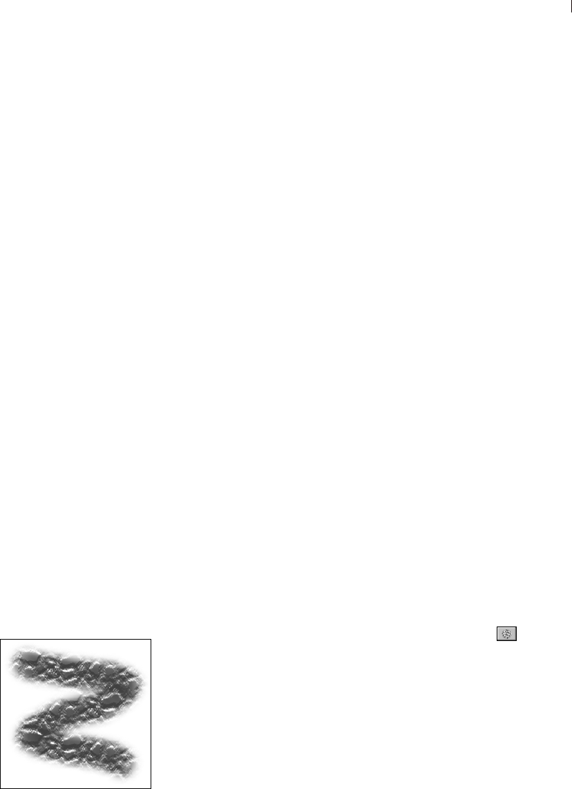
Chapter 10: Working with Colors and Materials 247
To use an image as a pattern:
1 Open the image you want to use.
2 To select a part of the image as the pattern, make a selection in
the image.
3 Follow the same steps as above for choosing a pattern and choose
the image from the Pattern Type drop-down list. If the image has
a selection, the selection rather than the entire image is available
as a pattern.
To create a new pattern:
1 Create an image (in Paint Shop Pro or another application).
2 Save the image as a file in the Patterns folder of the Paint Shop
Pro program folder.
Note: To change the default location of pattern files, on the
Material Properties dialog click the File Locations button in the
Pattern drop-list. See, “Editing File Locations” on page 68.
Choosing Textures
You can paint, draw, or fill with a texture to create interesting
effects. Textures give your images the effect of having a textured
canvas or paper. Paint Shop Pro includes many textures, such as
clouds, cracked cement, and old paper. You can create your own as
well. You use textures with the current style (solid color, gradient, or
pattern) for foreground and background strokes or fills. You can
apply strokes or fills multiple times to gradually darken and fill in
the texture.
To select the current texture for the foreground or
background material:
On the Materials palette, click the Texture style button on the
Foreground Material box or the Background Material box. The most
recently chosen texture becomes active.
To choose a new texture:
1 With the current style set to Texture, on the Materials palette do one
of the following:
To choose a foreground texture, click the
Foreground Material box.
Pattern versus texture
For a comparison of patterns and
textures, see “Understanding the
Difference Between Patterns and
Textures” on page 249.
Example of painting with
atexture
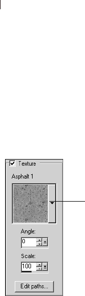
Chapter 10: Working with Colors and Materials
248
To choose a background texture, click the
Background Material box.
The Material Properties dialog opens.
2 Mark the Texture check box.
3 Click the Texture Type drop-list and select a type of texture.
4 Select the options for the texture:
Angle The angle (or direction) of the texture, from 0 to 359
degrees. You can also click and drag the control needle to change
the angle.
Scale The scale—from 10 to 250 percent of the image’s actual
size. At smaller values, the image is repeated more frequently
throughout the texture. At larger values, the image may be
cropped and may lose detail and become blurry.
As you modify the options, the Current color box displays the
resulting material (the style plus the texture).
5 To change the style of the material, click the Color, Gradient, or
Pattern tab and specify the options.
6 Click OK.
To create a new texture:
1 Create an image (in Paint Shop Pro or another application).
2 Save the image as a file in the Textures folder of the Paint Shop
Pro program folder.
Note: To change the default location of texture files, on the
Material Properties dialog click the File Locations button in the
Pattern drop-list. See, “Editing File Locations” on page 68.
The Texture panel of the
Material Properties dialog
Texture
Type
Where are texture files
stored?
The Texture Type drop-list displays
all the available files in the
Textures folder of the Paint Shop
Pro program folder. You can also
include .TEX files from previous
versions of Paint Shop Pro in this
folder.
Chapter 10: Working with Colors and Materials 249
Understanding the Difference Between
Patterns and Textures
On the Materials palette you can select both a pattern and a texture
as part of a material. What’s the difference between the two?
A pattern is an opaque, repeated image with specific colors and
details. A pattern is a style just like solid color or gradient. Thus,
patterns do not use the current foreground or background colors.
Let’s say you select the pattern called Bricks and then apply
brushstrokes with the Paintbrush tool. Each brush stroke paints the
brick pattern.
A texture gives the effect of having textured canvas or paper.
Textures use the current style (such as a solid color). Let’s say the
foreground color is yellow and you select the texture called
Crumpled Paper. When you apply a brush stroke, each brush stroke
paints yellow with the texture of crumpled paper.
Unlike patterns, textures can be applied at the same time as styles—
solid color, gradient, or pattern. That means you can have both a
pattern and a texture selected at the same time.
Working with Swatches
Swatches are materials that you can save to use again. For example,
if you create a material that is a certain shade of green with a fog
texture, you can save it as a swatch. Swatches are displayed on the
Swatches tab of the Materials palette.
To create a new swatch:
1 On the Materials palette, click the Swatches tab .
2 Click the Create New Swatch button . You can also click the
More Options button and choose New Swatch.
3 Type a name for the swatch. This name appears as a ToolTip
when you hold the cursor over the swatch on the Materials
palette.
4 Press OK to open the Material Properties dialog.
Painting with:
a pattern, a texture,
a pattern and a texture
An alternative way to create
aswatch
While you are selecting a material
on the Material Properties dialog,
click the Add to Swatches button
to create a new swatch of the
currently selected material.
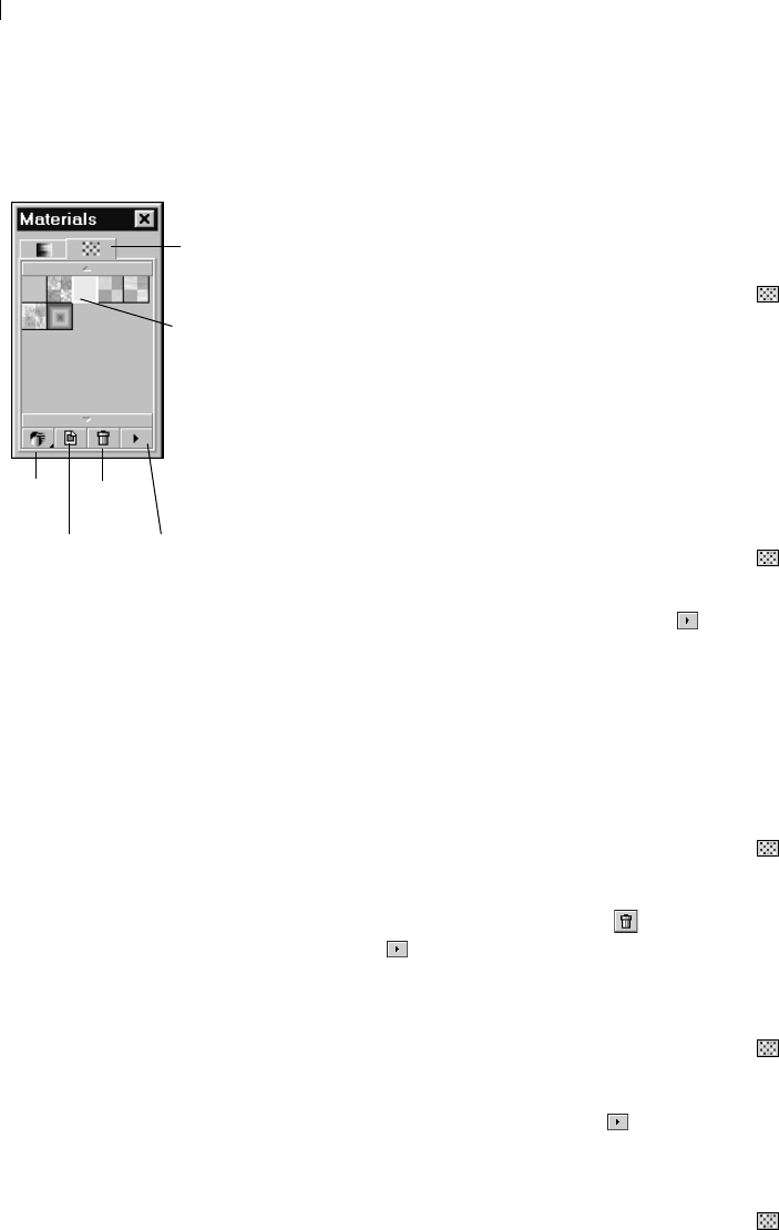
Chapter 10: Working with Colors and Materials
250
5 Select the style (color, gradient, or pattern) and the texture for the
material.
6 Click OK.
To select a swatch:
1 On the Materials palette, click the Swatches tab .
2 Do one of the following:
To select a swatch as the foreground material, left-click the
swatch you want to use.
To select a swatch as the background material, right-click the
swatch you want to use.
To edit a swatch:
1 On the Materials palette, click the Swatches tab .
2 Double-click the swatch you want to edit. You can also click the
swatch, click the More Options button , and then choose Edit
Swatch. The Material Properties dialog opens.
3 Edit the style (color, gradient, or pattern) or the texture for the
material.
4 Click OK.
To delete a swatch:
1 On the Materials palette, click the Swatches tab .
2 Click the swatch you want to delete.
3 Click the Delete Swatch button or click the More Options
button and choose Delete Swatch.
To rename a swatch:
1 On the Materials palette, click the Swatches tab .
2 Click the swatch you want to rename.
3 Click the More Options button and choose Rename Swatch.
To change how swatches are displayed:
1 On the Materials palette, click the Swatches tab .
The Swatches tab of the
Materials palette
Swatches
More Options
button
View
button
New Swatch
button
Delete
button
Swatches
tab
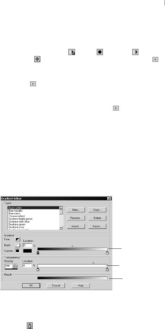
Chapter 10: Working with Colors and Materials 251
2 Do one of the following:
To select which swatch types are displayed, click the View
button and choose All , Colors , Gradients , or
Patterns . You can also click the More Options button ,
choose View, and then choose the swatch type to display.
To change how swatches are sorted, click the More Options
button , choose Sort, and then choose By Style or By Name.
By default, the swatches are sorted by style.
To change between small and large thumbnails of the
swatches, click the More Options button and choose Small
Thumbnails or Large Thumbnails. By default, small
thumbnails are displayed.
Editing Gradients
You can change the colors, transition points, and transparency of
gradients in the Gradient Editor dialog. You can edit Paint Shop
Pro’s default gradients or create your own gradients. You can also
rename, delete, import, and export gradients.
The Gradient Editor dialog is shown below.
To specify the colors and transition points of the gradient, use
settings in the Gradient group box. To change the transition points,
edit the location of markers and midpoints on the gradient bar:
Markers indicate points of solid color.
Editing the default gradients
If you edit and save one of the
gradients that comes with Paint
Shop Pro, you are permanently
changing the gradient type. For
example, if you select the Green
Neon gradient type, change its
colors to orange and yellow, and
save it. The next time you select
the Green Neon gradient type, it is
no longer green.
To maintain Paint Shop Pro’s
default gradients, save changes to
a new gradient file. See “Saving
Edited Gradients” on page 254. Gradient bar
Transparency bar
Result shows
gradient settings plus
transparency settings
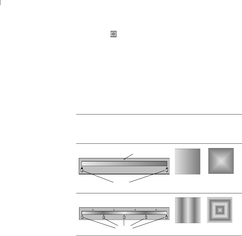
Chapter 10: Working with Colors and Materials
252
Midpoints indicate the positions where two colors are equally
blended. Each pair of markers has a midpoint that can be located
anywhere between the markers.
To specify the transparency of the gradient, including opacity values
and transition points, use the settings in the Transparency group box.
Markers and midpoints indicate the places where the transparency
changes. You change and add markers on the transparency bar,
which represents the transparency of the gradient across its width.
The following table shows example gradients that result from
different numbers of markers.
To display the Gradient Editor dialog:
1 On the Materials palette, click the Foreground Material box or the
Background Material box.
The Material Properties dialog opens.
2 Click the Gradient tab.
3 Choose the gradient you want to edit, then click the Edit button.
To change the location of markers and midpoints:
Do one of the following:
Click and drag the marker or midpoint to a new location.
How can I restore Paint
Shop Pro’s default
gradients?
Do a custom installation to
reinstall the gradients from the
Paint Shop Pro program disk.
For more information, see
“Installing the Software” on
page 6.
These Gradient Marker Locations Produce
this Linear
Gradient
Produce this
Rectangular
Gradient
Markers
Midpoint
Markers

Chapter 10: Working with Colors and Materials 253
Click the marker or midpoint to select it, then enter a value in the
Location field.
To add a new marker:
Click a position under the gradient bar or the transparency bar.
For the gradient bar, the marker’s initial color is determined by the
currently highlighted Fore, Back, or Custom button. Click another
color button to change the color.
For the transparency bar, the marker’s initial opacity is 100%.
Change this value in the Opacity edit box.
To delete a marker:
Click the marker and drag it away from the gradient bar or the
transparency bar.
To change the color for a marker:
1 Click the marker below the gradient bar to select it. The triangle at
the top of the marker turns black.
2 Choose a color by doing one of the following:
To use the foreground color, click the Fore button .
To use the background color, click the Back button .
To use the currently defined custom color, click the Custom
button .
To choose a new custom color, left-click the Custom color box
to select from the Color Picker or right-click to select from
recently used colors.
To select a color from within the gradient itself, click the
gradient bar.
To change marker transparency:
1 Click the marker below the transparency bar to select it. The
triangle at the top of the marker turns black.
2 Change the value in the Opacity edit box. Values range from 0%
(completely transparent) to 100% (opaque—the underlying
pixels are covered completely).
If a gradient uses
foreground or background
colors
If a gradient contains the
foreground or background color,
when you next apply the gradient it
uses the current foreground and
background colors of the image
(rather than the colors that you
used to define the gradient).
To create a gradient that always
contains the same colors, color all
markers with custom colors.

Chapter 10: Working with Colors and Materials
254
Saving Edited Gradients
After editing a gradient via the Gradient Editor dialog, you can save
the gradient as follows:
1 Click the Copy button. This displays the Copy Gradient dialog.
2 Enter a unique name for the gradient, and then click OK.
3 You'll see a message asking to confirm that you wish to save the
gradient. Click Yes.
Creating New Gradient Types
You can create a new gradient type that is selectable from the drop-
down list of the Gradient tab of the Material Properties dialog. If you
use the foreground and background colors to define the gradient, the
image’s current foreground and background colors are used when
you apply the gradient. To create a gradient type that always uses the
same colors, use custom colors for all markers.
To create a new gradient type:
1 Display the Gradient Editor dialog.
2 Click the New button.
3 Type a name for the new gradient.
4 Click OK.
The gradient is initially defined with two markers at 0 and 100% that
use the custom color. You can now edit the gradient.
Exporting Gradients
After creating a new gradient, you may want to export it to use in
another program. Although Paint Shop Pro’s default gradients are
stored in .PspGradient format, you export gradients as .GRD format,
which is commonly used in other applications.
To export a gradient:
1 Display the Gradient Editor dialog. See “To display the Gradient
Editor dialog:” on page 252.
2 If you have not already selected the gradient to export, choose it
from the Types box and edit its settings as desired.
3 Click the Export button.
How do I get my .GRD
format gradient to be
listed?
To have a .GRD format gradient be
listed as a gradient type, you must
import it. See “Importing Gradients”
on page 255.

Chapter 10: Working with Colors and Materials 255
4 Select the folder in which to save the gradient. Paint Shop Pro’s
default gradients are stored in the Gradients folder within the
Paint Shop Pro program folder.
5 In the File name edit box, type a name for the new gradient.
6 Click the Export button.
Importing Gradients
You can import gradients in the .GRD file format, which is a format
used in other applications.
To import a .GRD gradient:
1 Display the Gradient Editor dialog. See “To display the Gradient
Editor dialog:” on page 252.
2 Click the Import button.
3 Select the folder containing the gradient you want to import. All
.GRD files are listed.
4 Select the gradient’s file name.
5 Click OK.
Renaming and Deleting Gradients
You can rename or delete gradient types.
To rename a gradient:
1 Display the gradient you want to rename in the Gradient Editor
dialog.
2 Click the Rename button. This displays the Rename Gradient
dialog.
3 Type the new name.
4 Click OK.
To delete a gradient:
1 Click the gradient you want to delete in the Gradient Editor dialog.
2 Click the Delete button. You'll see a message asking to confirm
the deletion.
3 Click Yes.
Importing Jasc gradient
files
To import a gradient saved in Jasc
Gradient format (.PspGradient),
place the file in the Gradients
folder. All .PspGradient files in that
folder are automatically listed as
available gradient types.
How can I restore Paint
Shop Pro’s default
gradients?
Do a custom installation to reinstall
the gradients from the Paint Shop
Pro program disk. For more
information, see “Installing the
Software” on page 6.

Chapter 10: Working with Colors and Materials
256
Understanding Color and Color Models
We usually think of color as a quality inherent in an object—a red
car or a green frog. But color is really what we see as a result of
three factors interacting: light, the object, and the observer. As rays
of light hit the object, the object absorbs some light and reflects
some light. We see the reflected light and perceive it as color.
Different colors reflect light of different wavelengths. Human eyes
are able to perceive thousands of colors in the visible spectrum of
light.
When you apply ink to paper, the colors we see result from the light
that the ink reflects. Computer monitors use emitted light rather than
reflected light—the colors we see result from light emitted from the
screen.
To describe how color is produced or perceived, we use color
models. Computer monitors display colors by producing varying
amounts of red, green, and blue light—the RGB color model. Human
eyes perceive color by its hue, saturation, and lightness levels—the
HSL color model. With Paint Shop Pro you can select colors using
either the RGB or HSL color model. You can also output images
using the CMYK (Cyan, Magenta, Yellow, Black) model, which is
used for high-end printing applications.
RGB Model
All colors on your computer screen are created by mixing red, green,
and blue light in varying proportions and intensities. Adding all the
colors together creates white.
Each primary color (red, green, and blue) is assigned a value from 0
(none of the color present) to 255 (the color at full strength). For
example, pure red is produced by combining a red value of 255, a
green value of 0, and a blue value of 0. Yellow is a combination of a
red value of 255, a green value of 255, and a blue value of 0. Setting
all three values to 255 produces white; setting all three values to 0
produces black. When all three colors are set to the same value (such
as 120, 120, 120), the result is grey.
HSL Model
The HSL model is based on how the human eye perceives color
using the characteristics of hue, saturation, and lightness. Each
characteristic is assigned a value from 0 to 255. The three
characteristics are described as follows:
Selecting the color model
RGB is the default color model. To
change your color model
preference, see “Display and
Caching Preferences” on page 61.
Paint Shop Pro uses your preferred
color model (RGB or HSL)
whenever color values are
displayed, such as with the
Dropper tool. When you select
colors from the Jasc Color Picker,
you are able to enter RGB or HSL
values regardless of your
preference setting.
The color model used to display
color values on-screen has no
effect on how colors are printed.
Choose a color model preference
that is easier for you to use.

Chapter 10: Working with Colors and Materials 257
Hue The color reflected from an object, such as red, yellow, or
orange. Each hue value is assigned based on its position on the color
wheel. On the Jasc Color Picker’s color wheel, colors are assigned
counterclockwise from the top. Red is at the top (value 0) and as you
move around the wheel the colors go through orange, yellow, green,
blue, purple, and back to red.
Saturation The purity or vividness of the color. Saturation represents
the amount of grey in the color, from 0 (entirely grey) to 255 (fully
saturated color).
Lightness The perceived amount or intensity of light in the color.
Lightness ranges from 0 (no light, or black) to 255 (total lightness,
or white). At 50 percent lightness, or a value of 128, a color is
considered pure. For example, pure red has a hue of 255, a saturation
of 255 (100 percent) and a lightness of 128 (50 percent). For pure
blue, the hue is 170, saturation is 255 and lightness is 128.
CMYK Model
The CMYK model is based on the fact that ink on paper both absorbs
and reflects light. As white light strikes the ink, part of the color
spectrum is absorbed and part is reflected back to your eyes
(resulting in the color you see).
In this model, the primary colors cyan (C), magenta (M), and yellow
(Y) combine in varying proportions to produce a variety of colors.
When the three colors are combined, they produce black. Because
impurities in the ink make it difficult to produce a true black, a
fourth color, black (K), is added.
Combining inks in this way is called four-color process printing. It is
used by printing services and high-end color printers.
Although you cannot create images in Paint Shop Pro using the
CMYK model, you can produce color separations that can be printed
on CMYK printers. There are two ways to do this: You can split the
images into CMYK channels or you can print color separation pages.
CMYK channels are simply four separate greyscale images that
represent the percentage and location of cyan, magenta, yellow, and
black in the image. For more information, see “Working with Color
Channels” on page 259.
When you print CMYK separations, Paint Shop Pro prints a separate
greyscale page for each primary color. You can then use these pages
as “color plates” to give to a printing service. For more information,
see “Printing with CMYK Color Separations” on page 452.

Chapter 10: Working with Colors and Materials
258
How Monitor and Print Colors Differ
Computer monitor colors and printed colors may often be quite
different—which is a challenge when you are trying to match a
certain color. Colors can also appear different from monitor to
monitor.
Image colors on a monitor are influenced by a variety of factors: the
color range, called the color gamut, of the input device (such as the
scanner or camera), the manufacturer and age of the monitor, and the
monitor’s brightness and contrast settings.
When you print an image, you introduce other factors that influence
color: the quality and absorption properties of the paper, the color
gamut of the printer, and the conversion of RGB values from the
monitor to the CMYK values of the printer’s ink.
This conversion is a challenge because of the different approaches to
color between monitors and printers. Because monitors use light to
display color, they use additive colors—when you add them
together, they produce white. Conversely, when you remove all
monitor colors you produce black. Because printers use ink to
display color, they use subtractive colors—when you remove colors,
you produce white, and when you add all printer colors you produce
black. As a result, monitors and printers have different color gamuts.
Although they share many of the same colors, there are some colors
a monitor can display that a printer can’t print and some colors a
printer can print that a monitor can’t display.
Given all the factors that go into producing colors, how do you go
about making colors accurate and consistent? Try these options:
Calibrate your monitor every few months. See “Calibrating Your
Monitor” on page 84.
Get to know the typical differences between your monitor’s
colors and your printer’s colors so that you can adjust your
images as needed. Print out several photographs or other images
and compare them to the screen. Are there typical results? For
example, your printer may always print colors darker than your
monitor displays them. Knowing this, you can modify the
lightness of your images accordingly.
Consider using Windows Color Management, which helps to
improve color consistency across devices. See “Adjusting
Monitor Display Options” on page 84.
Additive
colors Subtractive
colors

Chapter 10: Working with Colors and Materials 259
Working with Color Channels
Image files store their color information in channels, or planes, of
colors. You can separate (or split) an image into RGB, HSL, or
CMYK color channels. An RGB image has three channels: red,
green, and blue. An HSL image has three channels: hue, saturation,
and lightness. Although you cannot create or edit an image using the
CMYK model, you can still split the image to four channels: cyan,
magenta, yellow, and black.
The Split Channel command creates a new greyscale image for each
color channel; the original image is not affected. For example, an
HSL image is split into separate greyscale images named “Hue,”
“Saturation,” and “Lightness.” Each greyscale image represents the
percentage and location of a color (such as red) or a characteristic
(such as lightness) within the image.
You can edit the greyscale images and use them to create interesting
effects or masks. You can combine them again using the Combine
Channel command. If you split an image into CMYK channels, you
can then send the four greyscale images to a printing service. (You
can also print CMYK separations directly; see “Printing with CMYK
Color Separations” on page 452.)
To split color channels:
1 Open the image.
2 Choose Image > Split Channel and choose RGB, HSL, or CMYK.
A new greyscale image opens for each color channel.
To combine color channels:
1 Open each color channel file.
2 Choose Image > Combine Channel and choose Combine from
RGB, Combine from HSL, or Combine from CMYK.
3 For each Channel source drop-down list, select the name of the
file that contains that channel. For example, in the Combine RGB
dialog, you might select the file Red1 as the red channel source.
Note: If you are combining channels that you split with the Split
Channels command, mark the Sync check box to have Paint
Shop Pro automatically fill in the Channel Source boxes with
matching file names.
4 Click OK. Paint Shop Pro displays a new image file that
combines the color channels you selected.
Does it matter what color
model is selected?
No. You can split images into RGB,
HSL, or CMYK color channels
regardless of the type of color
model (RGB or HSL) you chose as
a display preference.
Color channels are planes of
color. This RGB image has
three channels: red, green, and
blue.
Creative ideas for
color channels
Here are a few of the things you
can do with color channels:
Create a color shift by splitting an
image into HSL channels,
modifying the Hue channel, then
combining the channels.
Use a channel greyscale to
create a selection.

Chapter 10: Working with Colors and Materials
260
Understanding Color Depth
Color depth, also called bit depth, refers to the number of colors
each pixel (and therefore its image) can display. As the color depth
increases, the number of colors an image can display increases. Each
pixel’s color information is stored in a certain number of computer
bits—from 1 bit to 24 bits. In a 1-bit image, each pixel can display
only one of two colors (black or white). In a 24-bit image, each pixel
can display one of 16 million colors (224 or 2 colors for each bit).
Images with a color depth of 16 million colors look best because
they contain the most colors, but they also require the most memory
to store and edit.
In Paint Shop Pro, you can create 2 color (1-bit), 16 color (4-bit),
greyscale (8-bit), 256 color (8-bit), and 16 million color (24-bit)
images. Many of Paint Shop Pro’s effect and correction commands
work on 16 million color images only. Therefore, it is best to create
most images using 16 million colors. After you finish working on an
image, you can decrease its color depth and save it in another format.
Computer monitors also have a color depth that is determined by the
monitor’s capabilities as well as the selected color setting. If you
display an image with a higher color depth than the monitor can
display, the image will have some color distortion. Some file formats
limit the number of supported colors so that images display correctly
on a variety of monitor types. For example, GIF images, a popular
format for the Web, contain up to 256 colors (8-bit depth).
The number of colors actually used in an image is usually less than
the color depth. For example, in a 16 million color image, the image
is capable of displaying that many colors but may only use 50,000
colors. You can use the Layers > Count Layer Colors command to
count the number of colors in a layer of the image.
To view the color depth of an image:
Do one of the following:
Look at the Status bar, which displays the active image’s pixel
dimensions (the first two numbers) and color depth (the third
number).
Press F9 to display the Overview palette, click the Info tab, and
then view the Color Depth field.
Choose Image > Image Information, then look at the Pixel Depth/
Color field.
The color depth is the third
number in the Status bar (here
16 million colors).

Chapter 10: Working with Colors and Materials 261
To view the color depth of a monitor:
1 Choose Help > About Paint Shop Pro.
2 Click the System Info button.
3 Scroll down to the Video Driver Information section and look at
the Number of Colors field.
To view the number of colors in a layer:
1 On the Layers palette, click the layer name that you want to check.
2 Choose Image > Count Image Colors.
Increasing the Color Depth of an Image
If an image has a color depth less than 24-bit, you may want to
increase the color depth while editing the image. Many of Paint Shop
Pro’s effect and correction commands work only on images with 16
million colors. Depending on the color depth of your image, you can
also increase an image to 16 colors (4-bit) or 256 colors (8-bit).
To increase the color depth of an image:
Choose Image > Increase Color Depth and choose the desired color
depth: 16 Colors (4-Bit), 256 Colors (8-Bit), or 16 Million Colors (24-
bit). Color depths not available for the active image are greyed out.
Decreasing the Color Depth of an Image
If you are creating an image for on-screen viewing, you may want to
decrease the number of colors to make sure most monitors can
display the image properly. Also, when you have finished editing an
image, you may want to decrease color depth to save memory space.
Note
If you are creating images for the Web, we recommend that you
work with 16 million colors (24-bit) images so that all Paint Shop
Pro commands are available. When you are ready to save the images,
use the GIF optimizer or JPEG optimizer, which automatically
decreases the color depth in the saved image but doesn’t change the
color depth or layers of your original .PspImage file.
Depending upon the current color depth of your image, you can
decrease its color depth to the following:
Viewing and adjusting
monitor settings
You can view the possible settings
for your monitor by following these
steps: click the Windows Start
button, choose Settings > Control
Panel, double-click the Display
icon, and then click the Settings
tab.
For information on adjusting your
monitor settings, see your
Windows documentation.
Quick color depth changes
If you are increasing or decreasing
several images to the same color
depth, you can add the color
depth’s button to the toolbar. For
more information, see
“Customizing Toolbars and Menus”
on page 56.
Limitations of decreasing
color depth
Keep in mind these limitations
when decreasing color depth:
Most Paint Shop Pro effect and
correction commands work on
16 million color and greyscale
images only.
When you decrease the color
depth, Paint Shop Pro first
flattens the image, merging the
data on all layers. However, you
can add vector layers to images
of any color depth.

Chapter 10: Working with Colors and Materials
262
2 colors (1-bit) Converts to a black and white image and drastically
reduces file size. See “Decreasing Color Depth to 2 Colors (1-bit)”
on page 262.
16 colors (4-bit) Converts to a color image with very limited colors.
Use this option if your image uses a small number of colors and you
want a smaller file size. See “Decreasing Color Depth to 16 Colors
(4-Bit)” on page 264.
256 colors (8-bit) Converts to a color image that works well for on-
screen viewing when your image will be viewed on a variety of
monitor types. This is a helpful color depth for images viewed on the
Web. See “Decreasing Color Depth to 256 Colors (8-Bit)” on
page 265.
32K or 64K colors (24-bit) Converts to 32,000 or 64,000 colors
within a 24-bit image. For images viewed on older monitors, this
color depth results in better refresh rates. See “Decreasing Color
Depth to 32K or 64K Colors (24-Bit)” on page 266.
X colors Converts to a color image with a number of colors that you
specify (from 2 to 256). This color depth can produce smaller file
sizes and faster download times for file formats such as GIF. See
“Decreasing Color Depth to a Selected Number of Colors” on
page 266.
Note
When you change the color depth, you permanently change the
colors of the image’s pixels. Before decreasing the color depth, do as
much editing as possible in your original image and save a backup
copy of the image that includes all layers.
Decreasing Color Depth to 2 Colors (1-bit)
To create a black-and-white image, you can decrease an image’s
color depth to 2 colors. If your image is already black and white
(perhaps it is a line drawing or a photograph to which you applied
the Threshold command), decreasing the color depth to 2 colors can
drastically reduce the file size.
When you decrease color depth to 2 colors, choosing from the
variety of options is not an exact science. Try out several different
combinations and see which produces your desired result.
Another way to create a
black-and-white image
You can use the Threshold
command to select the lightness
value threshold (from 1 to 255) at
which color pixels are changed to
black or white. With this command,
the color depth does not change.
For more information, see
“Creating Black-and-White Images”
on page 142.
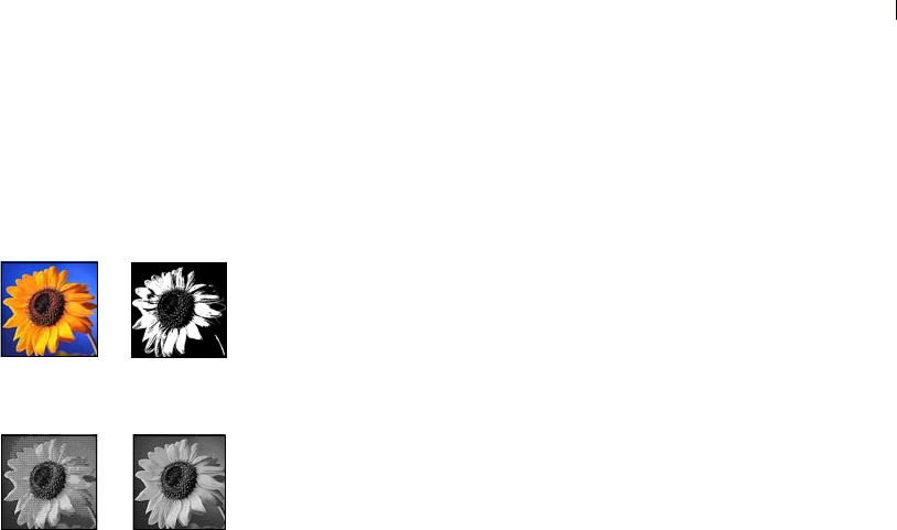
Chapter 10: Working with Colors and Materials 263
To decrease the color depth to 2 colors:
1 Choose Image > Decrease Color Depth > 2 Colors (1-bit).
2 In the Palette component group box, choose the color channel to
use for the final image: Grey (the lightness values), Red, Green,
or Blue. Choosing Grey produces the best results in most cases.
However, if the image consists mostly of a single color, selecting
that color channel may produce the best results.
3 In the Reduction method group box, choose a color reduction
method. See “About Color Reduction Methods” on page 267.
Note: With the Error Diffusion method, you must also select the
Floyd-Steinberg, Burkes, or Stucki option, which are algorithms
for the dithering pattern. Try them out to see what result you like
best.
4 In the Palette weight group box, select an option:
Weighted A weighted palette produces less dithering and
produces sharper edges.
Non-weighted A non-weighted palette produces more dithering
and softer edges.
Note: Dithering places pixels of different colors or grey levels
next to each other to simulate missing colors or greys.
5 Click OK.
Ordered Dither reduction
method and Error Diffusion
reduction method
Original color image and
Nearest Color reduction method

Chapter 10: Working with Colors and Materials
264
Decreasing Color Depth to 16 Colors (4-Bit)
To reduce the file size of images with few colors, decrease the color
depth of an image to 16 colors (4-bit). This color depth is especially
useful for simple graphics on Web pages that you want to load
quickly.
To decrease the color depth to 16 colors:
1 To emphasize the importance of certain colors in the conversion,
select an area of your image (optional).
2 Choose Image > Decrease Color Depth > 16 Colors (4-bit).
3 In the Palette group box, choose a palette option. See “About
Palette Options” on page 268.
4 In the Reduction Method group box, choose a color reduction
method. See “About Color Reduction Methods” on page 267.
Note: The Ordered Dither option is available only for the
Windows color palette.
5 In the Options group box, mark or clear these check boxes:
Boost marked colors by If you selected an area of your image,
you can mark this check box to make the colors in the selection
more important by a factor of the value you enter. The selected
colors will stand out from the rest of the image.
Reduce color bleeding If you chose the Optimized Median Cut or
the Optimized Octree palette and the Error Diffusion reduction
method, you can mark this check box to make the left-to-right
bleed effect of colors less noticeable.
6 Click OK.
Edit the palette
When you decrease color depth to
16 colors, the resulting image has
an image palette that contains 16
specific colors. You can change
any of those colors (and create
interesting effects) by editing the
image palette. See “Working with
Image Palettes” on page 269.

Chapter 10: Working with Colors and Materials 265
Decreasing Color Depth to 256 Colors (8-Bit)
To limit your image to colors most monitors can display and to
reduce file size, decrease the color depth of the image to 256 colors
(8-bit). You can choose a Web-safe palette that assures your image
displays properly on a variety of computer monitors.
To decrease the color depth to 256 colors:
1 To emphasize the importance of certain colors in the conversion,
select an area of your image (optional).
2 Choose Image > Decrease Color Depth > 256 Colors (8-bit).
3 In the Palette group box, choose a palette option. See “About
Palette Options” on page 268.
4 In the Reduction method group box, choose a color reduction
method. See “About Color Reduction Methods” on page 267.
Note: The Ordered Dither option is available only for the
Standard/Web-safe color palette.
5 In the Options group box, mark or clear these check boxes:
Boost marked colors by If you selected an area of your image
and you are using the Optimized Median Cut method, mark this
check box to make the colors in the selection more important by
a factor from 1 to 10. The selected colors will stand out from the
rest of the image.
Include Windows’ colors If you chose the Optimized Median Cut
or the Optimized Octree palette, you can mark this check box if
you want the 16 standard Windows colors included in the
converted image’s palette.
Reduce color bleeding If you chose the Optimized Median Cut or
the Optimized Octree palette and the Error Diffusion reduction
method, you can mark this check box to make the left-to-right
bleed effect of colors less noticeable.
6 Click OK.
Greyscale versus 256-color
images
Greyscale images can have 256
shades of grey; 256-color images
can have 256 colors. Both types of
images are 8-bit depth. However,
the Color Depth commands apply
to color images only.
If you want to create a greyscale
image from a color image, see
“Creating Greyscale Images” on
page 143.

Chapter 10: Working with Colors and Materials
266
Decreasing Color Depth to 32K or 64K Colors
(24-Bit)
To reduce the number of colors used in a 24-bit image, decrease the
color depth of an image to 32K (32,000) or 64K (64,000) colors.
Displaying images with 32K or 64K colors on older monitors results
in better refresh rates than displaying 24-bit images with 16 million
colors.
To decrease the color depth to 32K or 64K colors:
1 Choose Image > Decrease Color Depth and then choose 32K
Colors or 64K Colors.
2 In the Reduction method group box, select the method. See
“About Color Reduction Methods” on page 267.
3 Click OK.
Decreasing Color Depth to a Selected
Number of Colors
To select the number of colors in an image, use the X Colors
command to decrease the color depth of an image and reduce the file
size. If you specify 16 or fewer colors, the image is saved as a 4-bit
image. If you specify 17 to 256 colors, the image is saved as an 8-bit
image. For some file formats, particularly GIF, file compression is
sensitive to the number of colors in the image. For example, using
100 colors instead of 256 colors produces a smaller file size (and
produces faster download times), even though both files are 8-bit
images.
To decrease the color depth to a selected number of colors:
1 To emphasize the importance of certain colors in the conversion,
select an area of your image (optional).
2 Choose Image > Decrease Color Depth > X Colors (4/8-bit).
3 In the Number of colors edit box, enter the number of colors
(from 2 to 256) for the converted image’s palette.
4 In the Palette group box, select the palette options. See “About
Palette Options” on page 268.
5 In the Reduction method group box, choose a color reduction
method. See “About Color Reduction Methods” on page 267.

Chapter 10: Working with Colors and Materials 267
6 In the Options group box, mark or clear these check boxes:
Boost marked colors by If you selected an area of your image
and you are using the Optimized Median Cut or Optimized
Octree methods, mark this check box to make the colors in the
selection more important by a factor from 1 to 10. The selected
colors will stand out from the rest of the image.
Include Windows’ colors Mark this check box if you want the 16
standard Windows colors included in the converted image’s
palette.
Reduce color bleeding If you chose the Error Diffusion reduction
method, you can mark this check box to make the left-to-right
bleed effect of colors less noticeable.
7 Click OK.
About Color Reduction Methods
When you decrease an image’s color depth, you must select a color
reduction method. Depending upon the color depth you select, two
or three of these methods are available:
Nearest Color Replaces the original color of a pixel with the color in
the newly generated palette that is closest to the original RGB value.
This method eliminates dithering and produces a high-contrast
image. Simple graphics may look better with this method.
Error Diffusion Replaces the original color of a pixel with the most
similar color in the palette, but spreads the discrepancy between the
original and new color to the surrounding pixels. As it replaces a
color (working from the top left to the bottom right of the image), it
adds the “error,” or discrepancy to the next pixel, before selecting
the most similar color. This method produces a natural looking
image and often works best for photographs or complex graphics.
Ordered Dither Adjusts adjacent pixels so that two colors give the
illusion of a third color and intermingles pixels to produce patterns
based on a known palette. Use this method to give the image the
appearance of containing more colors than it actually does. Images
may appear to be composed of cross-hatches and dots and may have
distinct patterns of light and dark areas.
Give it a try
When you decrease an image’s
color depth, don’t be intimidated
by the mathematical algorithms
that make up the color reduction
methods and the palette options.
Your best bet is to start with the
default settings, see if you like the
result, and then try out several
other combinations of settings.
Finding the right options is not an
exact science—it takes some
experimentation.

Chapter 10: Working with Colors and Materials
268
About Palette Options
When you decrease an image’s color depth, you must select a palette
option. Depending upon the color depth you select, two or three of
these methods are available:
Optimized Median Cut Measures and ranks each color by how
frequently it occurs in the image, then uses the most frequently
occurring colors to determine the new palette. Even if your image
contains fewer colors than the palette that is generated, this method
may not represent each color exactly. The method, therefore, is not
as accurate as the Optimized Octree method, but it is better at
weighting color importance.
Optimized Octree Creates an eight-level “tree” with eight branching
nodes totaling 256 individual “leaves” or colors to determine the
new palette. This method attempts to reproduce each color in the
original image, so if your image contains fewer colors than the
palette that is generated, every color in the image is represented.
This method is faster and more accurate than Optimized Median Cut,
but it is not as good at weighting color importance.
Windows Changes each pixel’s color to the nearest color in the
Windows palette.
Standard/Web-Safe Palette Changes each pixel’s color to the nearest
color in the standard Web-safe palette. Use this method to create
images for the Web that can be viewed without color distortion on
most monitors.

Chapter 10: Working with Colors and Materials 269
Working with Image Palettes
An image palette is a collection of colors that an image uses—
similar to a painter’s palette of paints. An image palette is a subset of
all the colors your monitor can display.
Images with color depths of 16 to 256 colors have an image palette
that contains those colors that are used in the image. You can edit
this palette to fine-tune colors or create interesting color effects.
Images with a color depth of 16 million colors do not have an image
palette because they can contain all the colors your computer can
display. For these images, you can load an image palette to decrease
the image’s color depth to 256 colors or 8-bit. Loading a palette
produces the same result as using the Decrease Color Depth
command, except that you are controlling which colors are used in
the converted image. For more information on color depth, see
“Understanding Color Depth” on page 260.
Paint Shop Pro also includes a Safety palette for creating Web
images that can be viewed without color distortion on most
monitors. Using this palette produces the same result as using the
Decrease Color Depth > 256 Colors (8-bit) command and selecting
the Standard/Web-safe palette option. For more information, see
“Using the Web-Safe Color Palette” on page 271.
You can also create and save your own palettes. Preset palettes are
located in the Palettes folder of the Paint Shop Pro program folder.
You can store your custom palettes there as well.
To edit an image palette of 16 to 256 color images:
1 Choose Image > Palette > Edit Palette.
Note: This command is not available for 16 million color images.
2 To change the sort order (or arrangement) of colors, select an
option from the Sort Order drop-down list: Palette Order (in
order by the way the palette stores the colors), By Luminance (in
order by lightness) or By Hue (in order by color).
3 To replace a color, double-click it. The Color dialog opens and
displays the Jasc Color Picker. (For more information, see
“Choosing Colors from the Jasc Color Picker” on page 239.)
Make your selection and click OK. Notice that the image updates
with the new color. To return the palette to its original colors, on
the Edit Palette dialog click the Revert button.
4 Click OK.
Should I load a Web-safe
palette for Web images?
Not necessarily. When you load an
image palette into 16 million color
images, you decrease the color
depth to 256 colors, which flattens
all layers and makes many effect
and correction commands
unavailable.
Except when you want to control
the specific colors in a palette,
keep your image at a color depth
of 16 million colors in .PspImage
format. When you finish editing the
image, export it to GIF or PNG
format using a Web-safe palette.
Your original .PspImage file
remains intact for later editing. See
“Saving Images for the Web” on
page 459.
Editing the palette of a
greyscale image
If you select the Edit Palette
command for a greyscale image,
you are prompted to change the
image to 8-bit indexed color. Doing
so allows you to add color to your
greyscale image, similar to the
Colorize command.

Chapter 10: Working with Colors and Materials
270
To save an image palette:
1 Choose Image > Palette > Save Palette.
2 Select the folder where you want to save the palette. It’s most
convenient to save it in the Palettes folder of the Paint Shop Pro
program folder, where the preset image palettes are saved.
3 In the File name field, type a name for the palette. Paint Shop Pro
automatically adds the .PspPalette extension when you save the
file.
4 In the Save palette as group box, select a palette format:
PSP palette (the default) or Microsoft palette (for use with other
applications).
5 Click Save.
To load an image palette:
1 Choose Image > Palette > Load Palette.
2 Select the folder which contains the palette you want to load.
Preset image palettes are stored in the Palettes folder of the Paint
Shop Pro program folder.
3 Select the palette.
4 In the Apply palette using group box, select an option:
Nearest color matching Changes each image color to the color in
the palette that is the closest match.
Error diffusion dithering Attempts to maintain the image’s
appearance by dithering colors that are not in the palette.
Dithering places pixels of different colors next to each other to
simulate missing colors.
Maintain indexes Assigns each color in the palette a sequential
index number and does the same for each color in the image, then
changes each color in the image to the like-numbered color in the
palette.
5 Click Open. The palette is loaded and the image’s colors are
updated.
Why should I save a
palette?
When you save a palette, you can
load it into other images—a good
way to achieve consistent colors
across several images. Saving a
palette is also useful if you are
making many color changes and
want to save a backup copy of the
palette.
If you are using a palette with the
current image only, you don’t need
to save it as a separate file
because the palette colors are
saved with the image itself.
Color depth changes
When you load a palette, the color
depth of the image decreases, if
necessary, to match the number of
colors in the palette. For example,
if you load a 256 color palette into
a 16 million (24-bit) color image,
the image decreases to a 256 color
(8-bit) image.
What if I change my mind?
If you loaded a palette and now
you want to change it back to the
original palette or color depth, click
the Undo button or press Ctrl + Z,
or undo the action in the History
palette.

Chapter 10: Working with Colors and Materials 271
Using the Web-Safe Color Palette
Paint Shop Pro includes a Safety palette with 256 colors that are
Web-safe—your images can be viewed without color distortion on
most computer monitors. There are three ways to use this palette on
an image:
Load the Safety palette into your image. For 16 million color
(24-bit) images, this flattens the layers, reduces the image’s color
depth to 256 colors (8-bit), and makes many of Paint Shop Pro’s
effect and correction commands unavailable.
Decrease the image’s color depth to 256 colors and select the
Standard/Web-Safe Palette option. Decreasing the color depth
also flattens layers and makes some Paint Shop Pro commands
unavailable. For more information, see “Decreasing Color Depth
to 256 Colors (8-Bit)” on page 265.
Edit the image in 16 million colors (saving it in .PspImage
format), then use the GIF or PNG optimizer to export a copy of
the image. These optimizers use the Web-safe palette by default
and decrease the color depth in the saved image. We recommend
this alternative because it does not change the color depth or
flatten the layers of your original .PspImage file and keeps all
Paint Shop Pro effect and commands available. For more
information, see “Saving Images for the Web” on page 459.
To load the Web-safe color palette:
1 Choose Image > Palette > Load Palette.
2 Select the Palettes folder of the Paint Shop Pro program folder.
3 Select the palette Safety.pal.
4 In the Apply palette using group box, select an option:
Nearest color matching Changes each image color to the color in
the palette that is the closest match.
Error diffusion dithering Attempts to maintain the image’s
appearance by dithering colors that are not in the palette.
Dithering places pixels of different colors next to each other to
simulate missing colors.
Maintain indexes Assigns each color in the palette a sequential
index number and does the same for each color in the image, then
changes each color in the image to the like-numbered color in the
palette. This option is not available for 16 million color images.
5 Click Open.

Chapter 10: Working with Colors and Materials
272
Making a Palette Color Transparent
Paletted images (those with 256 or fewer colors, such as GIF or PNG
files) do not support transparent backgrounds, but you often need a
way to make part of your image transparent when displayed on a
Web page. For example, you may have a round logo and you want
the background of the Web page to display around the logo.
Most Web browsers can choose not to display one color, effectively
making it transparent. In Paint Shop Pro you have two ways to make
one color transparent:
Use the Set Palette Transparency command to make one color in
an image palette transparent. The color can be the background
color or any color from the image. To set a transparent color, the
image must have one layer only and must use an image palette,
which means the image must have a color depth less than 16
million colors (24-bit).
Edit the image in 16 million colors (saving it in .PspImage
format), then use the GIF or PNG optimizer to export a copy of
the image. With these optimizers you can set the transparency of
the image. We recommend this alternative because it does not
change the color depth or flatten the layers of your original
.PspImage file and keeps all Paint Shop Pro effect and commands
available. For more information, see “Saving Images for the
Web” on page 459.
If you decide to make one color transparent in your image, use the
Set Palette Transparency command to select the color, and then use
the View Palette Transparency command to display the transparent
color in your image. You can also use the Set Palette Transparency
command to change or undo the transparency of a color.
To make one image color transparent:
1 Choose Image > Palette > Set Palette Transparency.
2 If you are prompted to reduce the color depth and number of
layers, click Yes to continue and then choose the options for
decreasing color depth. For more information, see “Decreasing
Color Depth to 256 Colors (8-Bit)” on page 265.
Two logos displayed on a Web
page: without a transparent
color (top) and with a
transparent color (bottom)

Chapter 10: Working with Colors and Materials 273
3 On the Set Palette Transparency dialog, select an option:
To undo the transparency of a color, select No Transparency.
To make the background color transparent, select Set the
transparency value to the current background color.
To assign a specific color to be transparent, click the color on
the image itself, enter a value in the edit box of the Set the
transparency value to a palette entry option, or click the color
box to select from the current color picker.
4 To view the transparency on the image, click the Proof button.
5 Click OK. The color is now transparent; however, it may still be
displayed until you hide it.
To view or hide the transparency of a color:
Choose Image > Palette > View Palette Transparency.

Chapter 10: Working with Colors and Materials
274
275
Raster Painting
These tools give you endless options to get creative with your
images. Apply soft or hard-edged brush strokes of any color or
material, paint with another image as a source, retouch images to
correct colors or contrast, replace colors, or paint with picture tubes.
You can also erase pixels to transparency.
All painting tools (not to be confused with the Art Media tools,
which work on Art Media layers) work on raster layers only. The
raster painting tools are fully effective on greyscale or 16 million
color images, but can be applied with limited results to images of
other color depths.
You can also make a selection in an image and then use the painting
tool to change only the pixels within the selection. For more
information on selections, see “Using the Selection Tools” on
page 192.
Contents Setting Brush and Paint Options . . . . . . . . . . . . . . . . . . . . . . . 276
Painting with the Paint Brush or Airbrush . . . . . . . . . . . . . . . . . 278
Creating Brush Tips . . . . . . . . . . . . . . . . . . . . . . . . . . . . . . . . 280
Using the Brush Variance Palette . . . . . . . . . . . . . . . . . . . . . . 282
Filling Areas with Colors, Gradients, Patterns, or Textures . . . . 284
Warping Images With the Warp Brush . . . . . . . . . . . . . . . . . . . 286
Erasing Parts of an Image . . . . . . . . . . . . . . . . . . . . . . . . . . . . 287
Cloning Parts of Images . . . . . . . . . . . . . . . . . . . . . . . . . . . . . 290
Painting with Picture Tubes . . . . . . . . . . . . . . . . . . . . . . . . . . . 290
Replacing Colors . . . . . . . . . . . . . . . . . . . . . . . . . . . . . . . . . . 293
Retouching Images . . . . . . . . . . . . . . . . . . . . . . . . . . . . . . . . . 294
CHAPTER 11
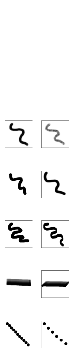
Chapter 11: Raster Painting
276
Setting Brush and Paint Options
The brush and paint options help you create hundreds of different
brush strokes when using the raster painting tools. Play with the
options until you get the effect you want.
Basic Brush Options
The following options are available on the Tool Options palette for
painting tools.
Shape The shape of the brush tip. Round and Square are the standard
brush tips. Choose Round to create curved strokes that look more
smooth or choose Square to create brush strokes with corners.
Choose the other shapes to create interesting effects. For information
on creating your own brush tips, see “Creating Brush Tips” on
page 280.
Size Determines the pixel size of the brush, from 1 to 500 pixels. If
the brush is asymmetrical (such as when the Thickness is set to
50%), the size is the brush height. Note that you can adjust the Size
value via the keyboard as well as through the Tool Options palette.
Refer to the Adjusting the Brush Size Via the Keyboard section on
the next page.
Hardness Determines how sharp the edges of the tool are. Setting
this to 100 gives you the sharpest, hardest edge; setting this to lower
values gives you an increasingly softer, fading edge.
Step Determines the distance placed between applications of paint
during a single (continuous) paint stroke. Lower Step values yield a
smoother, more continuous appearance; higher step values yield a
choppier appearance.
Density Determines the coverage of the paint step. (For the Eraser
tool, this setting determines the level of erasing.) Higher values yield
complete coverage; lower values yield spottier coverage as though
you're spraying the paint. Note that when using the Airbrush tool,
you should set Density to values lower than 100.
Thickness Determines how wide the brush is. Setting Thickness to
100 gives you a completely round or completely square brush
(depending on the Shape setting). As the Thickness setting
decreases, the brush becomes increasingly narrow.
Rotation The degrees of rotation of the brush tip, from 0 to 359.
Brush strokes with 75% and
25% densities
Brush strokes with 100% and
50% hardness
Brush strokes with
different thickness
Brush strokes with 0 and 45
degree rotation
Brush strokes with
different steps

Chapter 11: Raster Painting 277
Opacity How well the paint covers the image surface. At 100%
opac-ity, the paint covers everything. At 1% opacity, the paint is
almost transparent. For the Eraser tool, this setting determines the
level of erasing.
Blend mode How painted pixels are blended with pixels on
underlying layers. The blend modes are the same as layer blend
modes; for more information, see “About Blend Modes” on
page 373.
Continuous stroke Specifies whether paint builds up as you apply
multiple strokes of less than 100% opacity over the same area. If this
check box is marked, paint maintains a continuous color and
repaint-ing an area has no effect. If this check box is cleared (the
default), each brush stroke over the same area applies more paint;
the color darkens until it reaches 100% opacity.
Wet look paint Mimics wet paint, with soft color inside and a darker
ring near the edge. Decrease the Hardness setting from its maximum
of 100% to see the effect.
Adjusting the Brush Size Via the Keyboard
While using any Art Media tool, raster painting brush (with the
exception of the Warp brush), the Clone brush, the Color Replacer,
or the Eraser and Background Eraser, you can quickly adjust the
brush size without taking the cursor off the image and into the Tool
Options palette. To adjust the brush size via the keyboard:
Press Alt + X to decrease the brush size by one pixel.
Press Alt + C to increase the brush size by one pixel.
Hold down Alt and Shift and then press X to decrease the brush
size by 20 pixels.
Hold down Alt and Shift and then press C to increase the brush
size by 20 pixels.
Hold down the Alt key and drag (to drag, hold down the left
mouse button and then move the mouse) the left mouse button up
or down to rapidly change the brush size.
Hold down the Alt and Shift keys and drag the left mouse button;
the size will be set to its lowest value (3 pixels for the Art Media
tools, and 1 pixel for the raster painting tools) and then you can
drag to increase it from there.
What is an impression?
A brush impression is one click of
the painting tool. For example, if
you click once with the Paint Brush
tool using a round brush, the
impression is a circle. The same
round paint brush makes many
impressions as you drag the
cursor, which results in a stroke of
color.
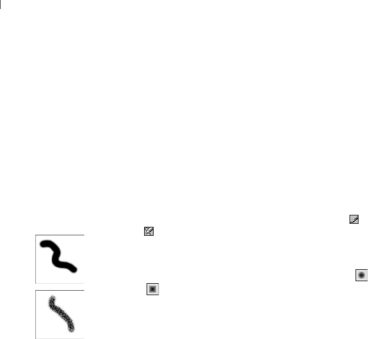
Chapter 11: Raster Painting
278
Painting with the Paint Brush or Airbrush
The Paint Brush and the Airbrush tools work in similar ways. Both
create strokes of color in a selection or an image and have a variety
of options for changing the brush stroke.
The Paint Brush tool creates strokes of color that simulates an
artist’s paint brush. Brush strokes can have hard or soft edges. The
Airbrush simulates an airbrush or spray can, and is time-dependent,
meaning, the longer you hold the brush over an area, the more the
brush produces the effect.
To use the Paint Brush or Air Brush:
1 On the Tools toolbar, choose the tool: Paint Brush or Airbrush
. (One tool may be hidden under the other.)
2 Choose the foreground and background colors and materials. See
“Choosing Colors” on page 239.
3 On the Tool Options palette, choose a shape: round , or square
. For information on creating your own brush tips, see
“Creating Brush Tips” on page 280.
Note: To create rectangular, elliptical, or angled brush tips, start
with the round or square shape and modify it using the Thickness
and Rotation options.
4 Specify the brush options such as size, opacity, hardness,
thickness, and rotation. See “If you are sharing a Preset for a
custom brush (brushes created from selections) then you will
need to select both the .PspBrush file and the associated PSP
Script file.” on page 282.
5 For the Airbrush, in the Rate edit box select the rate at which the
brush applies paint (from 0 to 50). Use a value of 0 if want to
apply a consistent amount of paint. Use higher values if you want
more paint applied when you drag the mouse slowly or pause the
mouse.
6 For the Paint Brush, set the following options:
Transparent painting
If you want a transparent paint
brush, use the Eraser or
Background Eraser tool. These
tools erase pixels to transparency
on raster layers. For more
information, see “Erasing Parts of
an Image” on page 287.
Painting with the Paint Brush
and the Airbrush
Default brush options
To reset brush options to their
default values, on the Tool Options
palette click the Presets drop-
down window and click the
Reset to Defaults button.

Chapter 11: Raster Painting 279
Continuous Stroke Specifies whether paint builds up as you
apply multiple strokes of less than 100% opacity over the same
area. If this check box is marked, paint maintains a continuous
color and repainting an area has no effect.
If this check box is cleared (the default), each brush stroke over
the same area applies more paint; the color darkens until it
reaches 100% opacity. Click the New Stroke button to cancel the
effect for all previous brush strokes. Only new brush strokes will
darken if you paint over them.
Wet Look Paint Mimics wet paint, with soft color inside and a
darker ring near the edge. Decrease the Hardness setting from its
maximum of 100% to see the effect.
7 Drag in the image to paint as follows:
For all painting tools, to apply the foreground material, drag
with the left mouse button.
For all painting tools, to apply the background material, drag
with the right mouse button.
For all painting tools, to paint a straight line, click once at the
beginning point, then press Shift and click the end point. To
continue the straight line, move to the next point and press
Shift and click.
For the Airbrush, to build up color in one area click and hold
the mouse at one position.
Using Brush Tip Presets
Use the tool Presets to save creative brush effects. You can choose
from many artistic presets or create, save, and share your own.
Brush Presets work just like other tool Presets.
To reset brush options to their default values, on the Tool Options
palette click the Presets drop-down window and click the Reset to
Default button .
For more information on presets, see “Using and Creating Presets”
on page 420.
Note:
Undoing paint strokes
When you are applying paint
strokes, the Undo command can be
your best friend. To remove the
most recent stroke, click the Undo
button or press Ctrl + Z. To undo
multiple brush strokes, press
Ctrl + Z multiple times. If you
undo too many strokes, click the
Redo button or press
Ctrl+Alt+Z. You can also use
the History palette to undo and
redo your actions.
Chapter 11: Raster Painting
280
Creating Brush Tips
You can create your own brush tips to use with painting tools. Select
a brush, modify the brush options and variance settings, and then
save the brush tip in the Brushes folder of the Paint Shop Pro
program folder. The next time you want to paint with that brush tip,
simply select it from the Brush Tip drop-down list.
You can also make a selection, and then turn that selection into a
custom brush with a width and height up to 500 by 500 pixels.
To create a brush tip:
1 On the Tools toolbar, choose a painting tool such as the Paint
Brush, Airbrush, or Color Replacer.
2 Modify the settings for the brush in the Tool Options and Brush
Variance palettes.
3 On the Tool Options palette, click the Brush Tip drop-down
window . Current brush tips are displayed.
4 Click the Create Brush Tip button , or choose File > Export >
Brush Tip to open the Create Brush Tip dialog.
Note: To save the new brush in a folder other than the default
Brushes folder, click the File Locations button in the Tool’s
presets drop-list.
5 In the Name field, type a name for the brush tip.
6 Complete the Author, Copyright, and Description fields.
7 Mark the Save Variance check box to save the brush variance
settings with the brush tip.
8 Click OK. You can now use the brush tip with one of the painting
tools.
To create a brush tip from a selection:
1 Make a selection of the area you want to convert into a custom
brush. The selection must be on a raster layer. For more
information on selections, see “Using the Selection Tools” on
page 192.
2 On the Tools toolbar, choose a painting tool such as the Paint
Brush, Airbrush, or Color Replacer.
3 On the Tool Options palette, click the Brush Tip drop-down
window . Current brush tips are displayed.
Brush tips versus tool
Presets
When you create a brush tip, you
are saving all of the options
selected for the brush, including
the brush shape, step, density,
thickness, size, hardness, and
rotation settings. You can also
include the variance settings. The
brush tip settings that you save
can be applied to any tool that has
a brush tip control in the Tool
Options palette. When you create
a tool Preset, you are savings all
the settings that you specified for a
particular tool, including all of the
parameters and variance settings.
The tool Preset is available only
when you select that particular
tool.
Chapter 11: Raster Painting 281
4 Click the Create Brush Tip from Selection button , or choose
File > Export > Brush Tip. A preview of the new brush appears in
the Create Brush Tip dialog.
Note: To save the new brush in a folder other than the default
Brushes folder, click the File Locations button in the tool’s
presets drop-list.
5 To set a default step value, select a step value.
6 In the Name field, type a name for the brush tip.
7 Complete the Author, Copyright, and Description fields.
8 Mark the Save Variance check box to save the brush variance
settings with the brush tip.
9 Click OK. You can now use the brush tip with one of the painting
tools.
To delete a custom brush:
1 On the Tools toolbar, choose a painting tool such as the Paint
Brush, Airbrush, or Color Replacer.
2 On the Tool Options palette, click the Brush Tip drop-list.
Current brush tips are displayed.
3 In the list of brush tips, select the brush tip that you want to
delete, and then click the Resource Manager button.
4 In the Resource Manager dialog, click Delete.
Saving and Sharing Brush Tips
Once you create a Preset for a brush you can save it in the Brushes
folder in the Paint Shop Pro program folder. You can then share your
brush Presets with others by sending them the brush file. If the brush
uses a custom shape, you will have to share both the brush file and
the custom shape file for that brush.
To save brush tip settings as a preset:
1 Click the down-arrow on the Presets button, and then click the
Save preset button to open the Save Preset dialog.
Importing Brush Tips
To import custom brush tips,
choose File > Import > Custom
Brush to open the Open dialog.
Select the location of the brush tip
and click OK to import the custom
brush tip.
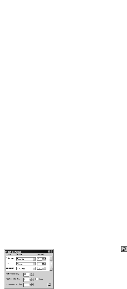
Chapter 11: Raster Painting
282
2 Type a name for the Preset.
Note: You cannot use the names “Default” or “Last Used”.
3 To enter additional Preset information, click the Options button,
and then enter information in the Author, Copyright, and
Description fields.
The Preset includes group box shows the data saved with this
Preset. To omit any of these items from the Preset, click the Save
icon (a red X will appear over it) associated with the data.
4 Click OK.
To share brush tip Presets:
1 Navigate to the brushes folder in the Paint Shop Pro program
directory.
2 Provide the brush file or files (brush files have a .PspBrush
extension) to the person with whom you want to share the brush
Preset. They should place the brush files in the Brushes folder in
the Paint Shop Pro program folder.
Note: If you are sharing a Preset for a custom brush (brushes
created from selections) then you will need to select both the
.PspBrush file and the associated PSP Script file.
Using the Brush Variance Palette
Use the Brush Variance palette to customize the brush settings in the
Tool Options palette. The variance settings modify the Tool Option
settings by applying adjustments to the settings for a particular tool
option. Adjustments can be randomized by increasing the Jitter
percentage.
Note
To reset brush variance options to their default values, click the
Reset to Default button on the Brush Variance palette.
To open the Brush Variance palette:
Choose View > Palettes > Brush Variance, or press F11.
To use the Brush Variance palette:
1 Choose a brush or eraser tool from the Tools toolbar.
2 Configure the brush options in the Tool Options palette.
Brush tips versus tool
Presets
When you create a brush tip, you
are saving all of the options
selected for the brush, including
the brush shape, step, density,
thickness, size, hardness, and
rotation settings. You can also
include the variance settings. The
brush tip settings that you save
can be applied to any tool that has
a brush tip control in the Tool
Options palette. When you create
a tool Preset, you are savings all
the settings that you specified for a
particular tool, including all of the
parameters and variance settings.
The tool Preset is available only
when you select that particular
tool.
The Brush Variance palette

Chapter 11: Raster Painting 283
3 On the Brush Variance palette, set the brush variance for each
available option:
Normal No variance applied.
Pressure The pressure applied from a tablet stylus.
Altitude The angle between the stylus and tablet.
Azimuth Determines the rotation angle of the tip.
Twist The rotation angle around the stylus (for 4D mouse
only).
Fingerwheel Applies to the wheel on an airbrush stylus.
Z-Wheel Used with a 4D mouse wheel with the wheel
configuration set to application defined behavior.
Direction The angle between consecutive mouse points on a
path.
Fade In Fades in the brush impression. For the Size option, the
brush size fades from small to large.
Repeating Fade In Repeatedly fades in the brush impression.
For the Size option, the brush size fades from small to large.
Fade Out Fades out the brush impression. For the Size option,
the brush size fades from large to small.
Oscillating Fade Repeatedly fades the brush impression in and
out. For the Size option, the brush size fades from small to
large to small.
Note: Options in the Variance palette marked with an asterisk
* apply only to users with a pressure sensitive tablet. The
options available will depend on the type of tablet being used.
4 Set the Jitter% for each available option. The higher the value,
the more randomly the option is applied.
5 For the Fade rate (pixels) select the number of pixels over which
the fade in and fade out will occur. Lower values produce a faster
fade, while higher values produce a slower fade.
6 For the Position Jitter (%) select a percentage for randomly
adjusting the brush impression location. Mark the Scale check
box if you want the jitter to scale with the brush size.
7 For Impressions per step indicate how many brush impressions
are made per step of the brush stroke.

Chapter 11: Raster Painting
284
Filling Areas with Colors, Gradients, Patterns, or
Textures
Use the Flood Fill tool to fill a selection or a layer with the
foreground or background color and material. You can fill all pixels
or fill only those pixels that match options that you specify. When
you click in the image, the Flood Fill tool finds and fills all
contiguous (adjacent) pixels that match the pixel you select.
To use the Flood Fill tool:
1 On the Tools toolbar, choose the Flood Fill tool .
2 Choose the foreground or background color and material to fill
the area with. See “Choosing Colors” on page 239.
3 On the Tool Options palette, specify the Match Mode options:
Match Mode How pixels that match the pixel you click are chosen
and filled:
None has no matching criteria and so fills all pixels.
RGB fills contiguous pixels that match the red, green, and blue
values.
Color fills contiguous pixels that match the hue and saturation
values.
Hue fills contiguous pixels that match the hue value.
Brightness fills contiguous pixels that match the brightness.
All Opaque fills all pixels that are opaque (not transparent).
Opacity fills contiguous pixels that match the opacity.
Tolerance How closely the selected pixels must match the initial
pixel you click. The range is 0 to 200. At lower settings, only
pixels with very similar colors are filled. At higher settings, more
pixels are filled.
Sample Merged Mark this check box to choose pixels to fill
based on matching pixels from all layers merged together. Clear
this check box to choose matching pixels to fill in from the
current layer only.
What are contiguous
pixels?
Contiguous means “near, next, or
adjacent.” Contiguous pixels are
like continuous chains of matching
pixels radiating from the initial pixel
you click. When the Flood Fill tool
finds a pixel that doesn’t match, it
breaks the chain. Even if a pixel is
just one pixel away from a
matching pixel, it is discontiguous.
Flood Fill versus Color
Replacer
Because the Flood Fill tool can fill
pixels that match certain criteria
(such as RGB value), its effect is
similar to the Color Replacer tool.
Here are the differences:
The Flood Fill tool fills matching
pixels that are contiguous to the
initial pixel you click. The Color
Replacer changes pixels either
within its brush stroke or in the
entire layer.
The Color Replacer tool changes
colors based on their RGB value.
The Flood Fill tool changes
pixels based on RGB, hue,
brightness, or opacity values.

Chapter 11: Raster Painting 285
4 Select the Blend Mode options:
Blend Mode How filled pixels are blended with pixels of
underlying layers. The blend modes are the same as the Layer
blend modes; for more information, see “About Blend Modes” on
page 373.
Opacity The opacity for the fill. At 100% opacity, the paint
covers everything; at 1% opacity, the paint is almost transparent.
5 Position the cursor over the area of the selection or image that
you want to fill, and then do one of the following:
To fill with the foreground material, click the left mouse
button.
To fill with the background material, click the right mouse
button.
If the Match Mode is None, all pixels on the current layer are
filled. For all other Match Mode settings, the Flood Fill tool fills
matching pixels that are contiguous to the pixel you click.
Apply the tool only where
you want it
To limit the effects of this tool to a
specific area, first make a selection
in the image.
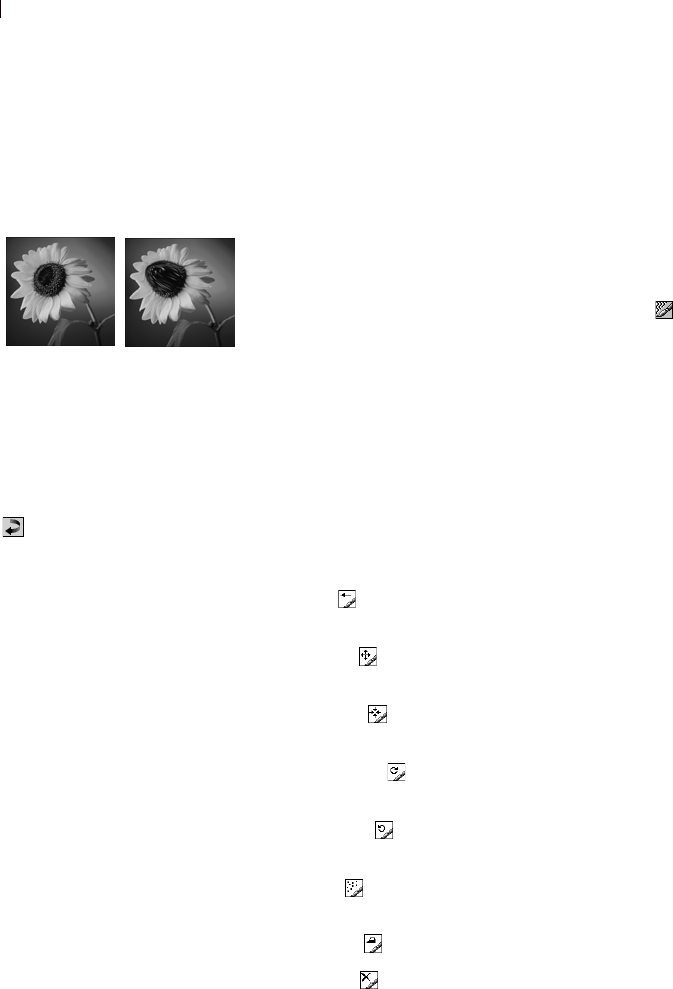
Chapter 11: Raster Painting
286
Warping Images With the Warp Brush
The warp brushes create strokes that produce a warping effect on
image pixels. You can twirl areas of images, contract or expand parts
of images, and create many interesting effects.
To use the Warp Brush:
1 On the Tools toolbar, choose the Warp Brush . (It may be hidden
under the Paint Brush or Airbrush.)
2 Specify the brush options such as shape, size, and hardness. See
“If you are sharing a Preset for a custom brush (brushes created
from selections) then you will need to select both the .PspBrush
file and the associated PSP Script file.” on page 282.
3 For the Strength value, enter a percentage (0 to 100) that
specifies how strong the warping effect is. Full strength is 100%;
minimum strength is 1%.
4 Under Warp Modes, choose the type of warp:
Push pushes pixels in the direction of the stroke (similar to
smearing paint) in a time-independent way.
Expand pushes pixels away from the center of the brush in a
time-dependent way.
Contract pulls pixels into the center of the brush in a time-
dependent way.
Right Twirl rotates pixels clockwise around the center of the
brush in a time-dependent way.
Left Twirl rotates pixels counter-clockwise around the center
of the brush in a time-dependent way.
Noise causes random movements of pixels under the brush in
a time-dependent way.
Iron Out removes unapplied warps in a time-independent way.
Unwarp removes unapplied warps in a time-dependent way.
5 Select an Edge mode, a Draft mode quality, and Final apply mode
quality. See “Warping Images Using the Mesh Warp Tool” on
page 178.
6 Do one or both of the following to warp the image:
Click and drag in the image.
Before and after applying the
Warp Brush tool
Default brush options
To reset brush options to their
default values, on the Tool Options
palette click the Presets drop-down
window and choose Default, or
click the Reset to Default button
.
What are time-dependent
warp types?
Time-dependent means that the
longer you hold the brush over an
area, the more the brush produces
the effect.
Another way to warp
images
You can also use the Mesh Warp
tool to warp images. See “Warping
Images Using the Mesh Warp Tool”
on page 178.
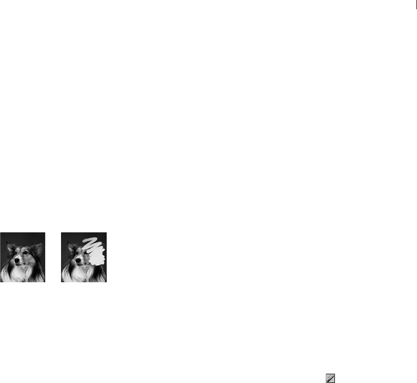
Chapter 11: Raster Painting 287
For the time-dependent modes, place the cursor at one
position and hold down the mouse button to repeat the effect
at one area.
7 To unwarp an area, choose the Iron Out or Unwarp option under
Warp Mode, and then click over the area you want to restore.
Continue clicking or holding the mouse button down until the
original pixel position is restored.
Erasing Parts of an Image
Use the Eraser tool to erase areas of a layer to transparency or to the
background color. Use the Background Eraser tool to selectively
erase to transparency—with options that determine which pixels are
erased.
Using the Eraser Tool
When you use the Eraser tool to erase on a raster layer, all pixels in
the tool’s path become transparent. When you erase on the
background (which does not support transparency), the Eraser tool
acts like a paintbrush; all pixels in the tool’s path become the current
foreground or background color or material.
To use the Eraser tool:
1 On the Tools toolbar, choose the Eraser tool . (It may be hidden
under the Background Eraser tool.)
2 On the Tool Options palette, choose the brush tip, size, opacity,
and other options. (See “If you are sharing a Preset for a custom
brush (brushes created from selections) then you will need to
select both the .PspBrush file and the associated PSP Script file.”
on page 282.) For the opacity setting, 100% erases pixels to
complete transparency and a lower opacity erases pixels to
partial transparency.
3 Drag in the image to erase as follows:
To erase pixels, drag with the left mouse button.
To restore erased pixels, drag with the right mouse button.
To erase a straight line, click once at the beginning point, then
press Shift and click the end point. To continue the straight
line, move to the next point and press Shift and click.
Before and after applying the
Eraser tool
Undoing versus erasing
When should you undo paint
strokes and when should you
erase in the image?
Undo paint strokes when you made
a mistake with a stroke. Undoing a
paint stroke restores the image
detail under the stroke.
Erase paint when you want to
change certain pixels to
transparent (or a color if the
background is selected). Erase to
create an effect—such as one
layer showing through another
layer. Erasing does not restore the
image detail under the stroke.
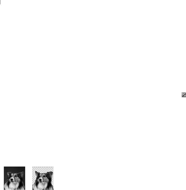
Chapter 11: Raster Painting
288
Note: If you erase on the background, the eraser strokes change
to the background color when you use the left mouse button or to
the foreground color when you use the right mouse button. To
erase to transparency, promote the background to a full layer.
Using the Background Eraser Tool
Use the Background Eraser tool to selectively erase pixels. For
example, in a photograph of a mountain range, you can erase the sky.
To use the Background Eraser tool:
1 On the Tools toolbar, choose the Background Eraser tool . (It
may be hidden under the Eraser tool.)
2 On the Tool Options palette, choose the brush tip, size, opacity,
hardness and other options. (See “If you are sharing a Preset for a
custom brush (brushes created from selections) then you will
need to select both the .PspBrush file and the associated PSP
Script file.” on page 282.) For the opacity setting, 100% erases
pixels to complete transparency and a lower opacity erases pixels
to partial transparency.
3 Choose from these additional options:
Tolerance How closely the selected pixels must match the
sampled pixel. The range is 0 to 200. At lower settings, only
pixels with very similar colors are erased. At higher settings,
more pixels are erased. (This edit box is unavailable if the
Auto Tolerance check box is marked.)
Sampling How the tool determines what pixels to erase:
Once samples at the center of the brush where you first click
and erases all matching pixels for the duration of the stroke.
Continuous samples at the center of the brush at every step
and erases all matching pixels.
BackSwatch erases all pixels that match the current
background color on the Materials palette rather than
sampling from the image.
ForeSwatch erases all pixels that match the current
foreground color on the Materials palette rather than sampling
from the image.
Before and after applying the
Background Eraser

Chapter 11: Raster Painting 289
Limits Whether erased pixels must be adjacent to each other:
Discontiguous erases all pixels in the tool’s path that match
the sampled pixels, even if they are discontiguous (non-
adjacent). Use this mode on images that show the background
through holes in the image.
Contiguous erases only contiguous pixels that match sampled
pixels. Use this mode when the background pixels are close in
color to the edges of the object you want to isolate.
Find Edges restricts the brush erasing according to the edge
information.
Auto Tolerance Mark this check box to have the tool
determine the tolerance based on the pixels in the Background
Eraser tool’s path; the tolerance may change continuously as
the tool moves over different parts of the layer. Clear this
check box to have the tool use the Tolerance setting that you
choose.
Sample merged Mark this check box to sample data from all
layers merged together; only pixels in the current layer are
erased. Clear the check box to sample data from the current
layer only.
Ignore lightness Mark this check box when the colors in the
object that you want to isolate are strongly saturated and the
background is unsaturated, or vice versa.
4 If the image has more than one layer, on the Layers palette click
the layer that has an object that you want to isolate by erasing the
background.
Note: The Background Eraser cannot be applied on the
background, which does not support transparency. If you apply
the tool to the background, you are prompted to promote it to a
full layer.
5 Drag on the layer, around the edges of the subject to erase the
background area as follows:
To erase pixels, drag with the left mouse button.
To erase a straight line, click once at the beginning point, then
press Shift and click the end point. To continue the straight
line, move to the next point and press Shift and click.
To restore erased pixels, drag with the right mouse button.
Sampling advice
For the Sampling option, choose
the Once setting to erase similar
colors while avoiding erasing areas
you want to keep. You can keep
clicking and dragging (in other
words, keep restarting the eraser
strokes) to erase similar areas.
If the area you want to erase is
quite variable, try using the
Continuous setting and set the step
value very low (even down to 1) so
that the area is sampled frequently
as you erase.
Auto or manual tolerance?
Start with the Auto Tolerance
check box marked. Begin erasing.
If too much or too little is erased,
clear the Auto Tolerance check
box. The Tolerance edit box
displays the automatically
determined tolerance. If too much
was erased, lower the tolerance. If
too little was erased, raise the
tolerance.
In addition, you can reduce the
step and increase the brush size.
To determine the automatic
tolerance, the Background Eraser
samples a larger area more
frequently.
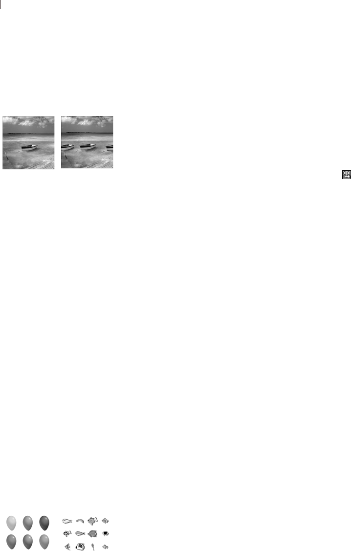
Chapter 11: Raster Painting
290
Cloning Parts of Images
The Clone Brush tool is a fun and powerful way to edit your images
by using parts of an image as a paint source. You can remove
elements within your image by painting over them with another part
of the image. The paint source can be part of the same layer, another
layer in the image, a merged image, or a layer from another image.
To use the Clone Brush:
1 On the Tools toolbar, choose the Clone Brush tool .
2 On the Tool Options palette, choose the brush tip, size, opacity,
and other options. See “If you are sharing a Preset for a custom
brush (brushes created from selections) then you will need to
select both the .PspBrush file and the associated PSP Script file.”
on page 282.
3 Mark the Aligned mode check box to have the Clone Brush tool
paint from the point of the source area relative to the first point
you click on the target area each time you stop and start painting.
You can keep clicking and dragging over the target area to fill in
the source image.
Clear the check box to have every stroke copy the same data.
4 Mark the Sample merged check box to clone data from all layers
merged together. Clear the check box to clone data from the
current layer only.
5 On the source image, right-click or press Shift and click the
center point of the source area.
6 Click and drag on the image you want to change to paint the
cloned area.
Painting with Picture Tubes
Use the Picture Tube tool to paint with a collection of objects
without having to draw them. You can add butterflies and beetles to
a picnic setting, fill an aquarium with fish, or frame a picture with
holly. Use one of the picture tubes included with Paint Shop Pro or
create your own.
Original image and image after
cloning
Why does nothing happen
when I apply the Clone
Brush?
If nothing appears to be happening
when you apply the Clone Brush,
make sure you selected a source
area with data. If the selected layer
has no data at the source point, but
another layer does have data there,
it may appear that you selected a
source area.
On the Layers palette, click the
name of a raster layer before you
define the source area. Also, make
sure the layer doesn’t have a
selection or, if it does, make sure
you right-click within the selection.
Two examples of picture tubes

Chapter 11: Raster Painting 291
Picture tubes are .PspTube files. Each picture tube file is made up of
a series of images arranged in rows and columns that are called cells.
Picture tubes may have any number of cells. As you paint with the
Picture Tube tool, Paint Shop Pro paints one image of a picture tube
after another. Many picture tubes create discrete images (such as
traffic signs), while some create the effect of a continuous image
(such as crepe paper).
Note
To use Paint Shop Pro version 9 picture tubes with Paint Shop Pro
version 7, copy the version 9 tubes with the .PspTube extension to
the picture tube directory in version 7, and then re-name the files
with the .TUB extension.
To paint with a picture tube:
1 On the Tools toolbar, choose the Picture Tube tool .
2 On the Tool Options palette, click the Picture Tube drop-down
window and select a picture tube.
Note: Most picture tube previews show one image rather than all
images in the picture tube. To view all images, paint with the
picture tube, or open the .PspTube file with the Browser.
3 If necessary, adjust the following options:
Scale The percentage (10 to 250%) to reduce or enlarge each
image in the picture tube and scale the step.
Step The distance in pixels (1 to 500) between the centers of each
picture tube image that you paint.
Placement mode The way images are placed: Continuous evenly
spaced by step size or Random random spacing between 1 pixel
and the step size.
Selection mode How Paint Shop Pro selects images to paint from
the cells within the picture tube: Random selects images
randomly; Incremental selects images one by one from top left to
the bottom right; Angular selects images based on the direction
you drag the cursor as you paint; Pressure selects images based
on the pressure you apply on a pressure-sensitive tablet; Velocity
selects images based on the speed you drag the cursor as you
paint.
4 To paint one image of the picture tube, click once in the image.
To paint multiple images, drag in the image.
Raster only
The Picture Tube tool paints raster
objects on raster layers. You
cannot use the tool on vector
layers.
To make picture tube elements
easier to edit, it is helpful to paint
them on a separate layer.
Changing default values for
picture tubes
To change default values for a
picture tube, including the
placement mode, step size, and
selection mode, click the Settings
icon on the Tool Options palette.
You can also change the number of
cells in the picture tube.
After you change values, mark the
Save as Default for this Picture
Tube check box and click OK.
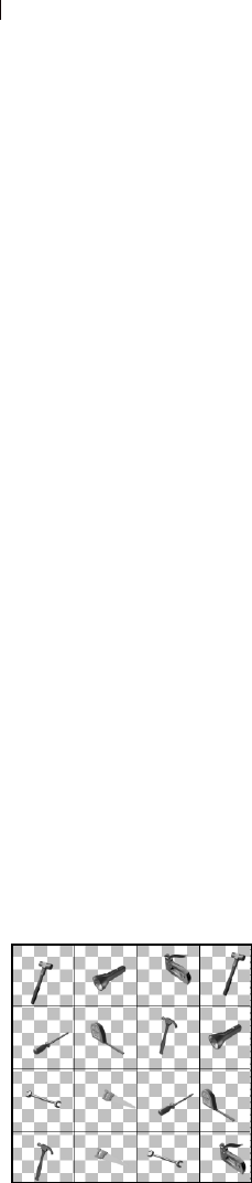
Chapter 11: Raster Painting
292
Creating Picture Tubes
To create your own picture tubes, create a grid of cells and then fill
each cell with an image. The cells can be any size, but picture tubes
with larger cells require more memory to use.
To create a picture tube:
1 Choose View > Change Grid, Guide, and Snap Properties, click
the Grid tab, set the current horizontal and vertical grids, then click
OK.
The grid positions are the value in pixels that the width and
height of cells will be. Images can be no larger than this cell size.
2 Choose File > New to open the New Image dialog.
3 Set the following options:
Image Dimensions Choose a width and height (in pixels) that are
multiples of the horizontal and vertical grid spacing. The width
and height of the image determine the total number of cells in the
image. For example, if the grid spacing is 100 pixels, create an
image of 400 pixels wide by 300 pixels high to have 12 cells
(four across and three down).
Image Characteristics Choose Raster Background as the layer
type and mark the Transparent check box.
4 Click OK.
5 If the grid is not visible, choose View > Grid.
6 Create one image in each grid square. These squares are the
picture tube cells.
Note: To change the size of cells, change the grid size and then
use the Canvas Size command to change the canvas size.
7 Choose File > Export > Picture Tube to open the Export Picture
Tube dialog.
8 Set the following options:
Cell arrangement Enter the number of cells across and down.
Placement options Choose the default options for this picture
tube. You can change these options when you apply the picture
tube. For more information, see the descriptions on page 291.
Color depth and layers
This tool works only on raster
layers in greyscale and 16 million
color images. To convert a vector
layer to a raster layer, choose
Layers >
Convert to Raster Layer. To
increase the color depth of an
image, see page 261.
Painting with one image
To use an entire image as a paint
brush, export the image as a
picture tube. Use a cell
arrangement of one cell across by
one cell down. The image must
contain one raster layer that is not
the background; to promote the
background to a layer, choose
Layers > Promote to Layer.
Then choose the Picture Tube tool
and select the new picture tube
you created.
Filling the cells of a picture tube

Chapter 11: Raster Painting 293
Tube name Enter the file name of the tube. The extension
.PspTube is automatically added to the file name.
Note: By default, picture tube files are stored in the Picture
Tubes folder of the Paint Shop Pro program folder.
9 Click OK. The picture tube is saved.
10 Close the image file. To edit it later, save it as a .PspImage or
other format file.
Replacing Colors
Use the Color Replacer tool to replace one color in a selection or
layer with another color. You can use brush strokes to replace only
those pixels that the brush touches or you can replace all pixels of a
certain color in a selection or a layer. You can set a tolerance value
so that the Color Replacer changes similar, not just identical, colors.
To use the Color Replacer tool:
1 On the Tools toolbar, choose the Color Replacer tool . The tool
may be hidden under the Eye Dropper tool.
2 Choose the color to replace as the foreground or background
color. See “Choosing Colors” on page 239 or “Choosing Colors
from an Image or the Desktop” on page 242.
3 Choose the color to substitute as the other color (foreground or
background).
4 To replace colors using brush strokes (rather than all colors in the
layer), on the Tool Options palette choose the brush tip, size,
opacity, and other options. See “If you are sharing a Preset for a
custom brush (brushes created from selections) then you will
need to select both the .PspBrush file and the associated PSP
Script file.” on page 282.
5 In the Tolerance edit box, specify a value that sets how closely
the selected pixels must match the initial pixel you click. The
range is 0 to 200. At lower settings, only pixels with very similar
colors are replaced. At higher settings, more pixels are replaced.
6 Position the cursor over the area of a selection or layer that
contains the color you want to replace, and then do one of the
following:
To replace all occurrences of a color, double-click.
To replace using brush strokes, drag in the image.
I want more picture tubes!
There are a variety of Web sites
that offer free picture tubes. Start
with Jasc.com and click Free
Downloads. Or search the Web for
“free picture tubes.”
Apply the tool only where
you want it
To limit the effects of this tool to a
specific area, first make a selection
in the image.
Nothing seems to happen
when you apply the Color
Replacer tool...
Make sure you have selected a
foreground or background color
that is in the image. If there are no
pixels that match, then no pixel
colors are replaced.
To pick a foreground or background
color directly from the image, see
“Choosing Colors from an Image or
the Desktop” on page 242.
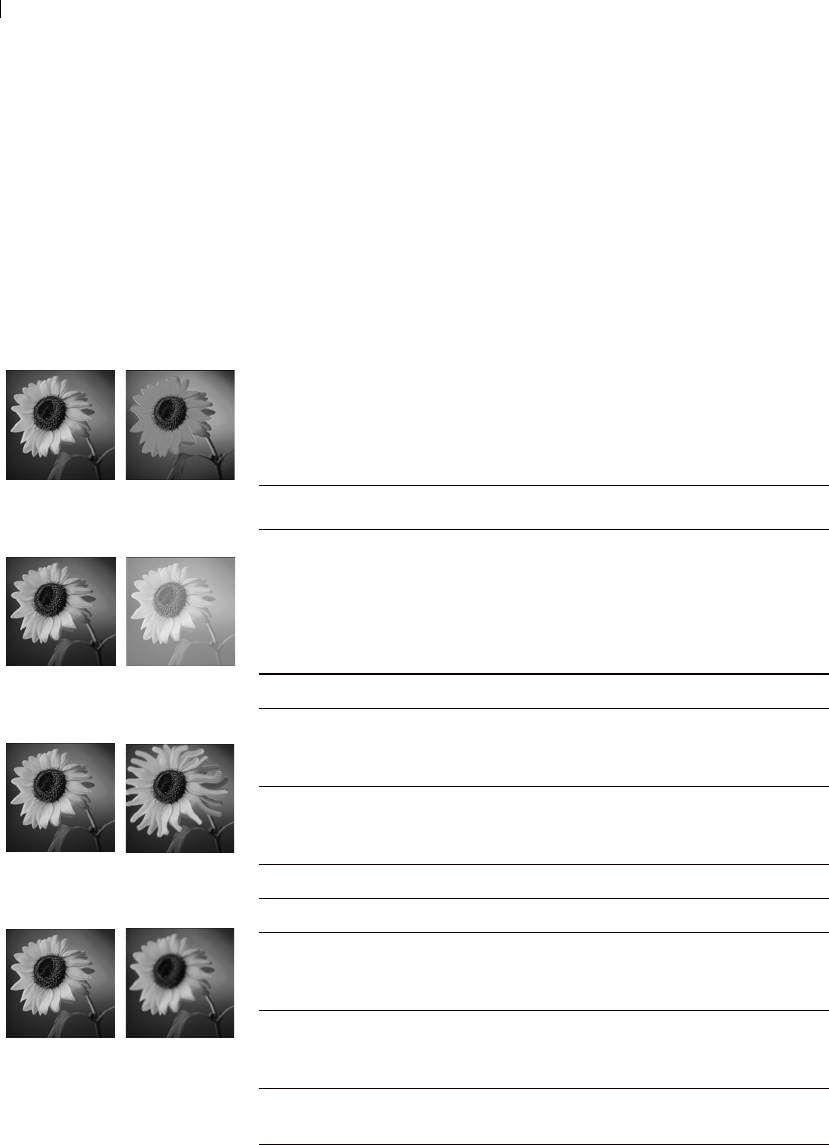
Chapter 11: Raster Painting
294
For both options, use the left mouse button to replace the
background color with the foreground color and use the right
mouse button to replace the foreground color with the
background color.
Retouching Images
You can retouch images with Paint Shop Pro’s retouch brushes,
which apply changes with brush strokes. Some retouch brushes
mimic photographic effects while others change pixels based on
their lightness, saturation, hue, or color values. Some retouch
brushes create similar effects to Paint Shop Pro’s color correction
commands. The following table describes each of the retouch
brushes.
Before and after applying the
Emboss brush
Before and after applying the
Dodge brush
Before and after applying the
Smudge brush
Before and after applying the
Soften brush
Brush Effect
Dodge Lightens and brings out the details in areas that are
in shadow. This tool mimics the traditional
photographic darkroom technique of holding back
some of the light when printing photographs to
produce lighter areas. The Dodge tool is the opposite
of the Burn tool.
Burn Darkens areas of the image that are too light.
Smudge Spreads color and image details from the starting
point and picks up new color and image details as it
moves; the effect is similar to smearing paint.
Push Spreads color and image details from the starting
point but does not pick up any new color or image
details.
Soften Smooths edges and reduces contrast.
Sharpen Heightens edges and accentuates contrasts.
Emboss Causes the foreground to appear raised from the
background by suppressing color and tracing edges
in black.
Lighten/Darken Lightening increases brightness; darkening
decreases brightness. (Choose to affect the RGB or
Lightness value of pixels).
Saturation Up/Down Increases or decreases the saturation (affects the
HSL value of pixels).
Chapter 11: Raster Painting 295
To use a retouch brush:
1 On the Tools toolbar, choose the retouch brush: Dodge , Burn ,
Smudge , Push , Soften , Sharpen , Emboss , Lighten/
Darken , Saturation , Hue , or Change to Target .
2 On the Tool Options palette, choose the brush tip, size, opacity,
and other options. See “If you are sharing a Preset for a custom
brush (brushes created from selections) then you will need to
select both the .PspBrush file and the associated PSP Script file.”
on page 282.
3 Depending upon the tool, select from the following options:
Swap mouse buttons Mark this check box to swap the functions
of the left (up) and right (down) mouse buttons.
Sample merged (Smudge, Push, Soften, Sharpen, Emboss) Mark
this check box to retouch data from all layers merged together.
Clear this check box to retouch data on the current layer only.
Mode (Lighten/Darken) Choose what is lightened or darkened:
RGB values or Lightness values.
Mode (Change to Target) Choose the characteristic of the
foreground color to target: Color (RGB value; luminance is not
changed), Hue, Lightness, or Saturation.
Limit Choose which option you want to limit for the Dodge and
Burn tools: None, Shadows, Midtones, or Highlights.
Hue Up/Down Increases or decreases the hue (affects the HSL
value of pixels).
Change-to-Target Changes pixels based on a characteristic of the
current foreground color (on the Materials palette):
color, hue, saturation, or lightness.
If you choose the color as the target, the tool applies
the foreground color without affecting the
luminance.
If you choose the hue, saturation, or lightness as the
target, it applies the foreground color’s hue,
saturation, or lightness value without changing the
other values.
Brush Effect
Apply the brush only where
you want it
To limit the effects of this brush to a
specific area, first make a selection
in the image.
Using the mouse buttons
When using the retouch tools you
can retouch an image by
left-clicking, and apply the
opposite of the retouch by right-
clicking.

Chapter 11: Raster Painting
296
4 Drag in the image to apply the brush. If the brush has two
functions (such as Hue Up/Down), drag with the left mouse to
apply the first function and drag with the right mouse button to
apply the second function.

297
Art Media Tools
Working in conjunction with the new Mixer palette, the new Art
Media tools let you create digital artwork that closely mimics real-
world media, pigments, paints, and artist's tools. The Oil Brush
creates realistic paint strokes, while the Chalk, Pastel, Crayon,
Colored Pencil, and Marker tools are used for making dry-pigment
works of art.
Contents Art Media Layers . . . . . . . . . . . . . . . . . . . . . . . . . . . . . . . . . . 298
Using the Mixer Palette . . . . . . . . . . . . . . . . . . . . . . . . . . . . . . 299
Using the Art Media Brushes . . . . . . . . . . . . . . . . . . . . . . . . . . 305
Using the Oil Brush . . . . . . . . . . . . . . . . . . . . . . . . . . . . . . . . 308
Using the Chalk Tool . . . . . . . . . . . . . . . . . . . . . . . . . . . . . . . 310
Using the Pastel Tool . . . . . . . . . . . . . . . . . . . . . . . . . . . . . . . 311
Using the Crayon Tool . . . . . . . . . . . . . . . . . . . . . . . . . . . . . . 312
Using the Colored Pencil Tool . . . . . . . . . . . . . . . . . . . . . . . . . 313
Using the Marker Tool . . . . . . . . . . . . . . . . . . . . . . . . . . . . . . 314
Using the Palette Knife Tool . . . . . . . . . . . . . . . . . . . . . . . . . . 315
Using the Smear Tool . . . . . . . . . . . . . . . . . . . . . . . . . . . . . . . 316
Using the Art Eraser Tool . . . . . . . . . . . . . . . . . . . . . . . . . . . . 317
CHAPTER 12
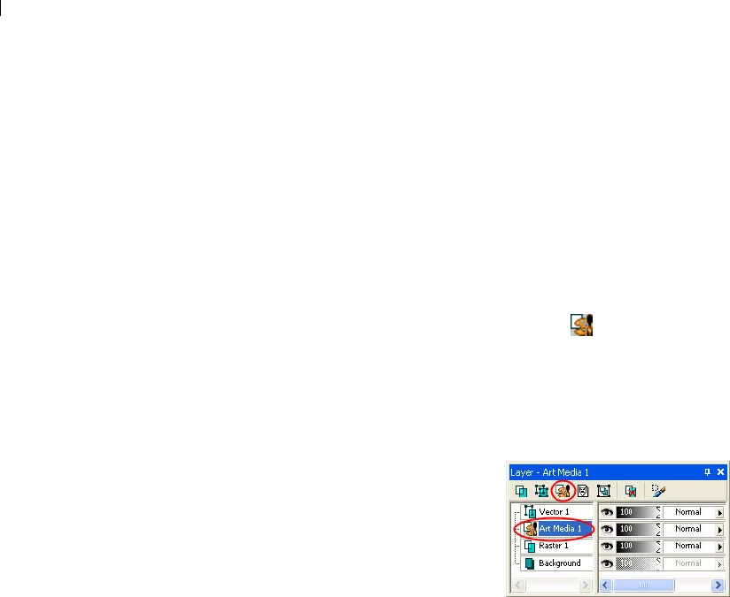
Chapter 12: Art Media Tools
298
Art Media Layers
Art Media layers are automatically created when you begin using
any of the Art Media tools. In this regard, the layer-creation
functionality is similar to the vector tools.
You can also create a new Art Media layer by doing any of the
following:
Choosing Layers > New Art Media layer; or
Clicking the New Art Media Layer button on the Layers
palette; or
Right-clicking on the Layers palette and choosing New Art
Media layer from the context menu.
In the Layers palette, Art Media
layers look like this:
Art Media layers can be converted
to Raster layers, but not Vector
layers.
Dry and Wet Art
Media Layers
Paint strokes applied by the Oil Brush and Palette Knife are, by
default, wet in terms of how strokes interact with other strokes by
smearing/mixing together. You can, however, choose to dry the Art
Media layer at any time. Conversely, you can choose to make a dry
Art Media layer wet again:
Choose Layers > Dry Art Media layer (or right click on the Layers
palette and choose Dry Art Media layer from the context menu)
to dry the strokes applied by the Oil Brush or Palette Knife.
Choose Layers > Wet Art Media layer (or right click on the Layers
palette and choose Dry Art Media layer from the context menu)
to make dried Oil Brush or Palette Knife strokes wet again.
Note: Note: Both the Dry Art Media layer command and the Wet
Art Media layer command can be selectively undone in the
History palette.

Chapter 12: Art Media Tools 299
Creating New Images with an Art Media
Layer
When creating a new image via the New Image dialog, you can
choose to create the image with an Art Media layer. To enhance the
realism, additional options include:
Setting a canvas texture on which Art Media pigment will be
applied.
Applying a fill color to the texture.
Modifying Art Media Layer Properties
After creating the new image, the texture and/or the fill color can be
changed. To do so:
1 Display the Layer Properties dialog by double-clicking the Art
Media layer in the Layers palette, or by highlighting the layer and
then choosing Layers > Properties.
2 Select the Canvas Texture tab.
3 Modify the texture and/or fill color setting.
Note: New textures applied after you've already applied Art
Media tool strokes will not affect these pre-existing strokes, but
instead just the strokes applied to the new canvas texture.
Using the Mixer Palette
The Mixer palette allows users to mix any number of colors into a
single paint swatch in a manner similar to a traditional artist's
palette. With this off-canvas palette, you can mix and experiment
with colors just like a real palette, and then use your Art Media
brushes to make realistic strokes simulating the rich, expressive
results you get with physical pigment media such as paint, pastel,
pencil, and chalk.
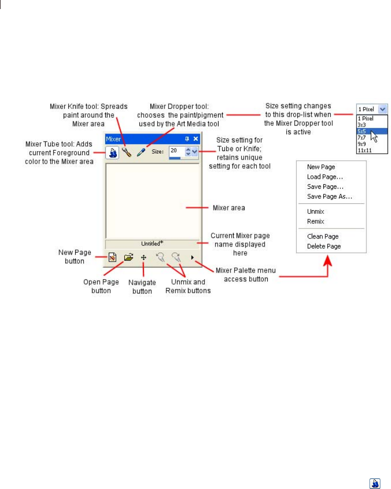
Chapter 12: Art Media Tools
300
Getting To Know the Palette
This illustration identifies the elements of the Mixer palette.
Painting with the Mixer Palette Materials
Here are the basics steps for painting with the Art Media tools and
the Mixer palette:
1 In the Materials palette, set the Foreground/Stroke property to
Color (the Mixer palette only works with the current Foreground/
Stroke solid color, not gradients, patterns, or textures), and then use
the Materials palette's Frame, Rainbow, or Swatch tab to choose the
color you want to start working with.
Note: Note: When any Art Media tool is active, the mode buttons
below the Foreground/Stroke and Background/Fill property
boxes will be inactive.
Note: In the Mixer palette, select the Mixer Tube tool .
2 In the Mixer area, lay down paint strokes by dragging the cursor.
The width of the stroke is determined by the Size setting for the
Tube tool.
Chapter 12: Art Media Tools 301
3 Optionally, you can set another Foreground/Stroke color in the
Materials palette like you did in Step 1, and again use paint
strokes in the Mixer area. Continue doing this as much as you
like. Use the Mixer area as you would a real-life painting palette.
Use the Unmix button to undo a Mixer Tube (or Mixer Knife)
action; use the Remix button to redo the undone action. You
can then save the Mixer area as a page as described in a section
below.
4 If you have multiple colors applied to the Mixer area, you'll
notice that strokes that pass over another color will mix the
colors just like a real-life palette. At this point you could also use
the Mixer Knife tool to smear Mixer area colors together. Use
the Unmix button to undo a Mixer Knife (or Mixer Tube)
action; use the Remix button to redo the undone action. Use
the Size setting to determine the stroke width for the Tube tool
and the Knife tool -- be aware that each tool's Size setting can be
unique.
Note: The Mixer Knife tool and the Mixer Tube tool exchange
functionality when dragging with the right mouse button. When
using the Tube tool, left-drag to apply paint, right-drag to mix
paint. When using the Knife tool, left drag to mix paint, right-
drag to apply paint.
5 When you're ready to begin painting, select the Mixer palette's
Mixer Dropper tool and then click the desired color in the
Mixer area. Notice that dragging the cursor around the Mixer
area updates the Materials palette's Foreground/Stroke property
in tandem with your current sampling position. Be aware of the
following points:
For the Oil Brush and Palette Knife tools, the Mixer palette's
Dropper tool's cursor size is determined by the Size setting in
the Tool Options palette.
For all the other Art Media tools (Chalk, Colored Pencil,
Marker, etc.), the sampling area is determined by the Mixer
palette's Size drop-list setting. The drop-list becomes active
when using any Art Media tool other than Oil Brush or Palette
Knife.
6 In the Art Media tools group in the Tools toolbar, select the
desired Art Media brush to use. The Oil Brush and Palette Knife,
by default, create wet paint strokes, while the other tools create
dry paint strokes. For details on each Art Media tool, see Using
the Art Media Brushes.

Chapter 12: Art Media Tools
302
Note: When using the Oil Brush or Palette Knife, you can choose
to "dry" the Art Media layer, or make it "wet" again by choosing
Layers > Dry Art Media layer or Wet Art Media layer. See the Dry
and Wet Art Media Layers section below for more details.
7 Place the Art Media brush cursor inside the image area and begin
making paint strokes. The strokes will be applied on an Art
Media layer. (If this layer type is not the active layer, one will be
created automatically once you begin using the Art Media tool.)
8 To get more paint, or choose another color, use the Mixer
palette's Dropper tool to click the desired color in the Mixer area.
Now go back to the image canvas and paint.
9 To clean the brush tip, click the Clean button in the Tool
Options palette, or mark the Auto Clean check box to
start with a clean brush tip for every stroke.
10 Experiment with the Tool Options palette settings to control
brush behavior.
Dry and Wet Art Media Layers
Paint strokes applied by the Oil Brush and Palette Knife are, by
default, wet in terms of how strokes interact with other strokes by
smearing/mixing together. You can, however, choose to dry the Art
Media layer at any time. Conversely, you can choose to make a dry
Art Media layer wet again:
Choose Layers > Dry Art Media layer (or right click on the Layers
palette and choose Dry Art Media layer from the context menu)
to dry the strokes applied by the Oil Brush or Palette Knife.
Choose Layers > Wet Art Media layer (or right click on the Layers
palette and choose Dry Art Media layer from the context menu)
to make dried Oil Brush or Palette Knife strokes wet again.
Note: Note: Both the Dry Art Media layer command and the Wet
Art Media layer command can be selectively undone in the
History palette.
Chapter 12: Art Media Tools 303
Navigating the Mixer Area
Use the Navigate button to pan around the Mixer area page:
1 Place the cursor over this button and then hold down the left mouse
button. This displays a small version of the entire 500 x 500 pixel
Mixer page, and a black outline box reflects the current view in the
Mixer area.
2 Drag the mouse to pan the page. Release the mouse button when
the desired portion of the page is enclosed in the outline box.
This feature works in a similar manner to the Overview palette.
Emptying the Mixer Area
To empty the mixer area (clean the page), do one of the following:
Choose Clean Page from the Mixer palette's menu access button
at the bottom right of the palette; or
Click the New Page button , and choose No when asked to
save the current page.
Saving Mixer Area Pages
To save the current Mixer area as a page, choose Save Page or Save
Page As in the Mixer palette's menu access button, and then enter a
name for the page.
Loading Mixer Area Pages
To load a previously saved Mixer area page, click the Load Mixer
Page button , or choose Load Page in the Mixer palette's menu
access button. Navigate to where the page resides to select it.
About the Unmix and Remix Buttons
The Mixer palette's Unmix and Remix buttons allow you to
undo Mixer Tube and Mixer Knife actions. Note the following points
about these buttons:
Unmix allows you to undo the 20 most recent Mixer Tube or
Mixer Knife actions.
The following page operations will clear the current history: New
Page, Load Page, Clean Page, and Delete Page.

Chapter 12: Art Media Tools
304
The Unmix/Remix functionality is limited to the current session
of Paint Shop Pro; if you exit the application, restart it, and open
the same image, the Unmix/Remix buttons are reinitiated.
Closing and opening the mixer palette will not reinitiate the
Unmix/Remix states.
Mixer Tube and Mixer Knife actions cannot be undon/redone by
choosing Edit > Undo / Redo, nor by clicking the Standard
toolbar's Undo and Redo buttons, nor by pressing Ctrl + Z or Ctrl
+ Alt + Z.
Creating a Custom Mixer Page
The Mixer pages you work on and save via the Mixer palette are 500
x 500 pixels. You can, however, create larger, custom mixer pages as
described below. (Note that Mixer pages cannot be smaller than 500
x 500 pixels.)
1 Create a new image by clicking the New button on the Standard
toolbar, or choose File > New. The New Image dialog appears.
2 In the Image Dimensions section, enter the desired dimensions
for the Mixer page. Remember that the Width and Height must be
at least 500 pixels.
3 In the Image Characteristics section:
Choose the Art Media Background option.
Choose a texture from the Texture drop list. The texture acts
like an invisible surface on which Art Media pigments are
applied.
4 Check the Enable fill color check box if you wish to fill the mixer
page with a color. Be aware, however, that you cannot sample
this color, nor will the Art Media tools affect the color.
5 If you marked the Enable fill color option, click the Color box
and choose a fill color.
6 Click OK to create the new image.
7 *Optional: At this point you can apply Art Media pigment to the
image.
8 Click the Save button on the Standard toolbar, or choose File
> Save. The Save As dialog appears.
9 Navigate to the current directory where your Mixer pages are
being read from this is set in the File Locations dialog. The
directory should either be:
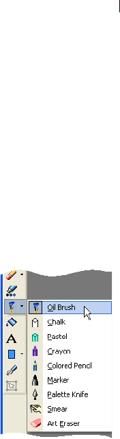
Chapter 12: Art Media Tools 305
...My Documents\My PSP Files\Mixer Pages; or
...Program Files\Jasc Software Inc\Paint Shop Pro 9\Mixer
Pages
10 Save the new image in the .PspImage file format.
When you now choose to load another Mixer page, the custom page
will be available.
Using the Art Media Brushes
The Art Media brushes and tools in the
Tools toolbar are shown here:
Use these tools when working on Art Media
layers. Like any other tool, the Art Media
tools have their own settings in the Tool
Options palette to control their behavior on
the image.
The purpose of these tools is to simulate the
rich, expressive results you get when
working on physical pigment media such as
paint, chalk, pastel, and pencil. The tools
will appeal not only to creative graphic artists, but also to photo-
centric users looking for ways to touch up their images.
Note: Although the Art Media tools support Presets, they do not
support custom brush tips like the Paint Brush and other raster
painting tools.
The Wet Pigment Media Tools
The Oil Brush and Marker tools simulate painting with a wet
pigment media. The Oil Brush further simulates wet painting in that
it will run out of paint during the stroke. To "get more paint," simply
release the mouse button, then hold it down again and drag more
paint strokes. You can also get more paint from the Mixer palette's
Mixer area.

Chapter 12: Art Media Tools
306
Note that the Oil Brush and the Palette Knife are the only Art Media
tools capable of producing strokes with multiple colors on the brush
head. This simulates what you could get using a real-life painting
palette with multiple wet pigments on it. Additionally, when the Oil
Brush or Palette Knife is active, you can "dry" wet strokes by
choosing Layers > Dry Art Media layer; conversely you can make
dried strokes "wet" by choosing Layers > Wet Art Media layer.
(These commands are also available in the Layers palette's context
menu.)
Note
Both the Dry Art Media layer command and the Wet Art Media layer
command can be selectively undone in the History palette.
The Dry Pigment Media Tools
The Chalk, Pastel, Crayon, and Colored Pencil tools simulate
artwork created with dry pigment media. Unlike the Oil and Acrylic
brushes, these dry tools don't "run out" of their respective pigment
media. Additionally, the pigment applied with these tools has less
volume than what is applied via the Oil Brush or Acrylic Brush.
The Palette Knife, Smear, and Art Eraser
Tools
The Palette Knife can be used to smear art media pigments with a
hard, knife-like edge, or it can be used to apply the pigments.
The Smear tool is to smear art media pigments as though you were
using a finger or cloth.
The Art Eraser tool is used to erase pigment from the Art Media
layer. When using the Art Eraser over areas covered with multiple
paint strokes (such as those applied by the Oil or Acrylic brushes),
you'll find that it may take multiple strokes with the Art Eraser tool
to clean the area. Conversely, using this tool on strokes applied with
the Chalk or Colored Pencil tool will yield quicker results.
For more details on each of these tools, click its associated link
below.

Chapter 12: Art Media Tools 307
Adjusting the Brush Size Via the Keyboard
While using any Art Media tool, raster painting brush (with the
exception of the Warp brush), the Clone brush, the Color Replacer,
or the Eraser and Background Eraser, you can quickly adjust the
brush size without taking the cursor off the image and into the Tool
Options palette. To adjust the brush size via the keyboard:
Press Alt + X to decrease the brush size by one pixel.
Press Alt + C to increase the brush size by one pixel.
Hold down Alt and Shift and then press X to decrease the brush
size by 20 pixels.
Hold down Alt and Shift and then press C to increase the brush
size by 20 pixels.
Hold down the Alt key and drag (to drag, hold down the left
mouse button and then move the mouse) the left mouse button up
or down to rapidly change the brush size.
Hold down the Alt and Shift keys and drag the left mouse button;
the size will be set to its lowest value (3 pixels for the Art Media
tools, and 1 pixel for the raster painting tools) and then you can
drag to increase it from there.
About the Trace Check Box
One particular Tool Options setting to be aware of is the Trace check
box. When this check box is marked, the current Art Media tool will
select the pigment/paint color by sampling the data below the center
of the brush regardless of the layer type. (This feature works much
the same way the Clone Brush's Sample Merged tool option works).
When you hold down the mouse button to begin the stroke, note that
a single sample is performed, and the resulting color is used for the
duration of the stroke.
This feature allows you to, for example, use the Art Media tools to
trace over a photo residing on the Background layer, using colors in
the photo as the pigment media source. With careful, detailed use of
this feature you could create an impressionistic effect similar to what
you can get with some of Paint Shop Pro's own effects or even third
party plug-ins such as Virtual Painter.
Be aware that when tracing over elements such as an eye or other
small, fine features, you'll get better results if you set your zoom
level appropriately as well as the brush size setting in the Tool
Options palette.

Chapter 12: Art Media Tools
308
Using the Oil Brush
Oils present a dense medium that blends color by mixing thick
medium rather than through an overlay function. The Oil Brush
can potentially be loaded with multiple colors across the head.
Mixing with oil already on the canvas results in smearing and
blending. Shininess is important, as well as the existence of texture
from the mass of medium on the canvas interacting with the bristles
of the brush, as well as the texture of the canvas.
There are a number of options for managing the reloading of the
Oil Brush tool head between strokes:
Reload with solid color from the materials palette
Reload with Art Media material from the Materials palette
Not loaded at all, but instead relying on the user to dip into the
palettes or canvas manually after each stroke.
These options helps to mimic real world paint tools while also
allowing the digital user to take a more convenient approach to
applying new paint strokes.
Dry and Wet Art Media Layers
Paint strokes applied by the Oil Brush and Palette Knife are, by
default, wet in terms of how strokes interact with other strokes by
smearing/mixing together. You can, however, choose to dry the Art
Media layer at any time. Conversely, you can choose to make a dry
Art Media layer wet again:
Choose Layers > Dry Art Media layer (or right click on the Layers
palette and choose Dry Art Media layer from the context menu) to
dry the strokes applied by the Oil Brush or Palette Knife.
Choose Layers > Wet Art Media layer (or right click on the Layers
palette and choose Dry Art Media layer from the context menu) to
make dried Oil Brush or Palette Knife strokes wet again.
Note: Both the Dry Art Media layer command and the Wet Art
Media layer command can be selectively undone in the History
palette.
Oil Brush Tool Options
Oil Brush tool options include:
Shape: Choices include Round or Square.
Art Media Brush Presets
Like other Paint Shop Pro tools,
the Art Media Brushes comes with
presets.
To use a preset:
In the Tool Options palette, click
the Presets button. This displays a
list of preset styles.
From the list, choose the desired
brush preset.

Chapter 12: Art Media Tools 309
Size: Defines the size of the tool head in pixels. Note that you can
also adjust the Size setting via the keyboard. Refer to the Adjusting
the Brush Size Via the Keyboard section earlier in this chapter.
Thickness: Defines the aspect ratio of the tool head. Note that this
setting is only active when the Fixed angle Head Tracking option is
chosen.
Rotation: Defines the angle of head rotation in degrees
Head Tracking: Choose Track path to have the brush head bend
around the path of the stroke, or choose Fixed angle to have the
brush head remain at a fixed angle.
Head Loading: Defines (in percentage) the amount of material on the
brush at the start of the stroke.
Viscosity: Defines the rate at which the material on the brush is
applied, and thus the length of the stroke before your paint runs out.
Firmness: Defines the amount of splay in the brush, how the
rendered line gets wider with more pressure, and how well it
penetrates the surface on to which it is painting.
Bristle size: Defines the bristle size affects the underlying noise
function for texture and application of paint.
Reloading: the method by which the brush is reloaded after a stroke.
As noted above this could involve requiring the user to "pick up"
paint from the canvas or mixer, automatically reloading, cleaning
and reloading the brush, or other options.
Auto Clean check box: When marked, this check box simulates
cleaning the brush and dipping it in fresh paint at the start of a new
stroke. When unchecked, the brush head is not cleaned at the start of
the stroke. Instead, the "dirty" head has a small amount of the current
color added to whatever dirty head state exists from the previous
stroke.
Clean button: Click this button to clean the head and start the next
stroke with fresh paint/pigment. Note that this button is only active
when the Auto Clean check box is not marked.
Trace check box: When marked, the current Art Media tool will
select the pigment/paint color by sampling the data below the center
of the brush regardless of the layer type. (This feature works much
the same way the Clone Brush's Sample Merged tool option works).
When you hold down the mouse button to begin the stroke, note that
a single sample is performed, and the resulting color is used for the
duration of the stroke.

Chapter 12: Art Media Tools
310
Note:
The Auto Clean check box and the Clean button are only available
with the Oil Brush and Palette Knife tools.
Using the Chalk Tool
Chalk presents a dry media with infinite head loading, meaning the
media does not "run out" over the course of a stroke like it does with
the Oil Brush. As applied by the Chalk tool , its dry pigment
tends to penetrate the canvas texture proportional to the pressure at
which you apply it. This is due to Paint Shop Pro mimicking a solid
tool head, combined with the chalk having a fixed viscosity. Chalk
does not have a bristle component to the stroke, but is instead
applied via the tool's flat or angled surface. The stroke edges tend to
have a fall-off and break up affected strongly by the current canvas
texture.
Chalk is a matte and powdery medium, so it doesn't tend to smear
itself much, though it does sink in to the dents in the canvas.
Because it is a hard pigment medium, chalk does not apply volume
to the surface of the canvas.
Chalk Tool Options
Chalk tool options include:
Shape: Choices include Round or Square.
Size: Defines the size of the tool head in pixels. Note that you can
also adjust the Size setting via the keyboard. Refer to the Adjusting
the Brush Size Via the Keyboard section earlier in this chapter.
Thickness: Defines the aspect ratio of the tool head.
Rotation: Defines the angle of head rotation in degrees
Head Tracking: Controls whether the tool head bends around the
path of the user’s stroke, or remains at a fixed angle.
Trace check box: When marked, the Chalk tool will select the
pigment color by sampling the data below the center of the tool
regardless of the layer type. (This feature works much the same way
the Clone Brush's Sample Merged tool option works). When you
hold down the mouse button to begin the stroke, note that a single
sample is performed, and the resulting color is used for the duration
of the stroke.
Art Media Brush Presets
Like other Paint Shop Pro tools,
the Art Media Brushes comes with
presets.
To use a preset:
In the Tool Options palette, click
the Presets button. This displays a
list of preset styles.
From the list, choose the desired
brush preset.

Chapter 12: Art Media Tools 311
Using the Pastel Tool
Pastel is a dry media, softer than chalk, but like chalk it has infinite
brush loading. Applied with the Pastel tool , its dry pigment tends
to penetrate the canvas texture proportional to the pressure at which
you apply it. Pastel pigments have a fixed viscosity slightly less than
chalk, meaning the strokes you apply leave some volume on the
canvas as they break from the pigment stick. Pastels do not have a
bristle component to the stroke, instead presenting a flat or angled
surface of the stick. The stroke edges tend to have a fall-off and
break up affected strongly by the canvas texture.
Pastel is slightly shiny, interacts with itself by smearing slightly, and
dirtying the tool head slightly when applied with light pressure. It
loads the canvas more than chalk, breaking up more when applied,
and this give the appearance of volume to the surface.
Pastel Tool Options
Pastel tool options include:
Shape: Choices include Round or Square.
Size: Defines the size of the tool head in pixels. Note that you can
also adjust the Size setting via the keyboard. Refer to the Adjusting
the Brush Size Via the Keyboard section earlier in this chapter.
Thickness: Defines the aspect ratio of the tool head.
Rotation: Defines the angle of head rotation in degrees
Head Tracking: Controls whether the tool head bends around the
path of the user’s stroke, or remains at a fixed angle.
Trace check box: When marked, the Pastel tool will select the
pigment color by sampling the data below the center of the tool
regardless of the layer type. (This feature works much the same way
the Clone Brush's Sample Merged tool option works). When you
hold down the mouse button to begin the stroke, note that a single
sample is performed, and the resulting color is used for the duration
of the stroke.
Art Media Brush Presets
Like other Paint Shop Pro tools,
the Art Media Brushes comes with
presets.
To use a preset:
In the Tool Options palette, click
the Presets button. This displays a
list of preset styles.
From the list, choose the desired
brush preset.

Chapter 12: Art Media Tools
312
Using the Crayon Tool
Crayon is a dry media similar to chalk though with a "wetter" feel
that prevents powdering, and the tool has infinite pigment loading.
As applied by the Crayon tool , its dry pigment tends to penetrate
the canvas texture proportional to the pressure at which you apply it.
This is due to Paint Shop Pro mimicking a solid tool head. The
pigment leaves a slightly waxy volume that can smear for a short
distance as it is painted over. Crayons do not have a bristle
component to the stroke, instead presenting a flat or angled tool
surface. The body of the stroke tends to have a fall-off and break up
affected strongly by the canvas texture, but although crayon pigment
is less transparent than chalk, it does not does not powder.
Crayon is a little more shiny than pastel, smears itself slightly less,
but does apply a tiny amount of matter to the canvas and can smooth
over bumps if used repeatedly. This is because the volume that is
laid down is viscous enough to fill dents but also dense enough to
prevent large-range smearing.
Crayon Tool Options
Crayon tool options include:
Shape: Choices include Round or Square.
Size: Defines the size of the tool head in pixels. Note that you can
also adjust the Size setting via the keyboard. Refer to the Adjusting
the Brush Size Via the Keyboard section earlier in this chapter.
Thickness: Defines the aspect ratio of the tool head.
Rotation: Defines the angle of head rotation in degrees
Head Tracking: Controls whether the tool head bends around the
path of the user’s stroke, or remains at a fixed angle.
Trace check box: When marked, the Crayon tool will select the
pigment color by sampling the data below the center of the tool
regardless of the layer type. (This feature works much the same way
the Clone Brush's Sample Merged tool option works). When you
hold down the mouse button to begin the stroke, note that a single
sample is performed, and the resulting color is used for the duration
of the stroke.
Art Media Brush Presets
Like other Paint Shop Pro tools,
the Art Media Brushes comes with
presets.
To use a preset:
In the Tool Options palette, click
the Presets button. This displays a
list of preset styles.
From the list, choose the desired
brush preset.

Chapter 12: Art Media Tools 313
Using the Colored Pencil Tool
Colored Pencils present a dry medium that doesn't tend to break up
but does apply solidly to the canvas. As applied by the Colored
Pencil tool , its pigment has a very strong interaction between
pressure and the canvas. The tool size is small compared to other
tools. Head-loading is infinite, and viscosity is very high. Pencil
doesn't apply bump to the surface, and will only smear when
pressure is applied with a less smooth tipped tool. To smear colored
pencil strokes, you would use the Smear tool.
Pencil strokes tend to blend with a multiply mode when used lightly,
but overlay when used with firm pressure. This can be used to
simulate a wide range of color blends, using the tool softly to apply a
hint of color, or firmly to cover over what’s underneath.
Colored Pencil Tool Options
Colored Pencil tool options include:
Shape: Choices include Round or Square.
Size: Defines the size of the tool head in pixels. Note that you can
also adjust the Size setting via the keyboard. Refer to the Adjusting
the Brush Size Via the Keyboard section earlier in this chapter.
Thickness: Defines the aspect ratio of the tool head.
Rotation: Defines the angle of head rotation in degrees
Head Tracking: Controls whether the tool head bends around the
path of the user’s stroke, or remains at a fixed angle.
Style: If you're using a stylus, you can choose Tilt to change the
style through a linear progression based upon the stylus tilt. Choose
Tip to mimic using the very tip of a pencil. Choose Edge to mimic
using the pencil's edge.
Softness: Defines the softness of the pencil lead, controlling how
easily pressure or velocity break up the lead and cause it to powder
into the canvas dents, or to smudge when applied.
Trace check box: When marked, the Colored Pencil tool will select
the pigment color by sampling the data below the center of the tool
regardless of the layer type. (This feature works much the same way
the Clone Brush's Sample Merged tool option works). When you
hold down the mouse button to begin the stroke, note that a single
sample is performed, and the resulting color is used for the duration
of the stroke.
Art Media Brush Presets
Like other Paint Shop Pro tools,
the Art Media Brushes comes with
presets.
To use a preset:
In the Tool Options palette, click
the Presets button. This displays a
list of preset styles.
From the list, choose the desired
brush preset.

Chapter 12: Art Media Tools
314
Using the Marker Tool
Marker pens are a slightly wet medium, though generally not wet
enough to interact with other wet media. As applied by the Marker
tool , its pigment goes on the canvas with a multiply function
when using pens, simulating the interaction of using a pen
repeatedly on the same spot. An imperfect hue will tend towards a
different color, very similar to the behavior of standard markers.
Marker ink tends to be semi-transparent, and can get darker when
applied with more pressure. Bristling generally does not occur since
pen tips tend to be firm or solid even if soft. Pens generally have a
very sharp fall-off at the stroke edge, and generally there is full
canvas penetration even at light pressure.
Marker Tool Options
Marker tool options include:
Shape: Choices include Round or Square.
Size: Defines the size of the tool head in pixels. Note that you can
also adjust the Size setting via the keyboard. Refer to the Adjusting
the Brush Size Via the Keyboard section earlier in this chapter.
Thickness: Defines the aspect ratio of the tool head.
Rotation: Defines the angle of head rotation in degrees
Head Tracking: Controls whether the tool head bends around the
path of the user’s stroke, or remains at a fixed angle.
Trace check box: When marked, the Marker tool will select the
pigment color by sampling the data below the center of the tool
regardless of the layer type. (This feature works much the same way
the Clone Brush's Sample Merged tool option works). When you
hold down the mouse button to begin the stroke, note that a single
sample is performed, and the resulting color is used for the duration
of the stroke.
Art Media Brush Presets
Like other Paint Shop Pro tools,
the Art Media Brushes comes with
presets.
To use a preset:
In the Tool Options palette, click
the Presets button. This displays a
list of preset styles.
From the list, choose the desired
brush preset.

Chapter 12: Art Media Tools 315
Using the Palette Knife Tool
The Palette Knife interacts with the mass of medium on the
canvas. Generally it would only interact with strokes placed by the
Oil Brush given that it is the only tools that apply large amounts of
its medium. As the mass of the medium reduces in a spot, there is
less to smear and using the Palette Knife has less effect. This means
that Crayon, which applies very little medium, will only be slightly
affected by the Palette Knife.
The method of loading or cleaning the Palette Knife mirrors the Oil
Brush in some ways. You can clean it automatically after each
stroke, retain the color picked up from the canvas, or allow manual
cleaning. The Palette Knife can be used to apply pigment or smear it,
depending on user preference.
Dry and Wet Art Media Layers
Paint strokes applied by the Oil Brush and Palette Knife are, by
default, wet in terms of how strokes interact with other strokes by
smearing/mixing together. You can, however, choose to dry the
Art Media layer at any time. Conversely, you can choose to make
a dry Art Media layer wet again:
Choose Layers > Dry Art Media layer (or right click on the Layers
palette and choose Dry Art Media layer from the context menu) to
dry the strokes applied by the Oil Brush or Palette Knife.
Choose Layers > Wet Art Media layer (or right click on the Layers
palette and choose Dry Art Media layer from the context menu) to
make dried Oil Brush or Palette Knife strokes wet again.
Note: Both the Dry Art Media layer command and the Wet Art
Media layer command can be selectively undone in the History
palette.
Palette Knife Tool Options
Palette Knife tool options include:
Shape: Choices include Round or Square.
Size: Defines the size of the tool head in pixels. Note that you can
also adjust the Size setting via the keyboard. Refer to the Adjusting
the Brush Size Via the Keyboard section earlier in this chapter.
Thickness: Defines the aspect ratio of the tool head. Note that this
setting is only active when the Fixed angle Head Tracking option is
Art Media Brush Presets
Like other Paint Shop Pro tools,
the Art Media Brushes comes with
presets.
To use a preset:
In the Tool Options palette, click
the Presets button. This displays a
list of preset styles.
From the list, choose the desired
brush preset.

Chapter 12: Art Media Tools
316
chosen.
Rotation: Defines the angle of head rotation in degrees
Head Tracking: Choose Track path to have the brush head bend
around the path of the stroke, or choose Fixed angle to have the
brush head remain at a fixed angle.
Head Loading: Defines (in percentage) the amount of material on the
brush at the start of the stroke.
Auto Clean check box: When marked, this check box simulates
cleaning the tool and dipping it in fresh paint at the start of a new
stroke. When unchecked, the tool head is not cleaned at the start of
the stroke. Instead, the "dirty" head has a small amount of the current
color added to whatever dirty head state exists from the previous
stroke.
Clean button: Click this button to clean the head and start the next
stroke with fresh paint/pigment. Note that this button is only active
when the Auto Clean check box is not marked.
Trace check box: When marked, the Palette Knife tool will select the
pigment/paint color by sampling the data below the center of the tool
regardless of the layer type. (This feature works much the same way
the Clone Brush's Sample Merged tool option works). When you
hold down the mouse button to begin the stroke, note that a single
sample is performed, and the resulting color is used for the duration
of the stroke.
Using the Smear Tool
Unlike the Palette Knife, the purpose of the Smear tool is to
smear existing pigment, including pigment that has no volume on the
canvas, such as pencil. This simulates using a cloth or finger to
softening out chalk or pencil strokes on a real-life canvas.
The Smear tool only interacts with pigment already on the canvas,
and has no loading of its own. When used on dry pigment, it will
have a smudge effect. When used on wet pigment, it will have a
smear effect.
This tool's functionality differs from real-life smearing in that its
operation changes based on the pigment type you're trying to smear.
But it does mimic the various real-life methods used to distort color
masses such as fingers on pencil, rags on oil, etc.

Chapter 12: Art Media Tools 317
Smear Tool Options
Smear tool options include:
Shape: Choices include Round or Square.
Size: Defines the size of the tool head in pixels. Note that you can
also adjust the Size setting via the keyboard. Refer to the Adjusting
the Brush Size Via the Keyboard section earlier in this chapter.
Thickness: Defines the aspect ratio of the tool head.
Rotation: Defines the angle of head rotation in degrees
Head Tracking: Controls whether the tool head bends around the
path of the user’s stroke, or remains at a fixed angle.
Using the Art Eraser Tool
The Art Eraser tool lets you erase art media from the image.
Specifically, it erases mass where there is some, and color where
there is not mass. While this tool is not strictly realistic, it does
provide important flexibility to the Art Media tool set, allowing you
to erase mistakes progressively rather than requiring an entire stroke
to be undone.
Art Eraser Tool Options
Art Eraser tool options include:
Shape: Choices include Round or Square.
Size: Defines the size of the tool head in pixels. Note that you can
also adjust the Size setting via the keyboard. Refer to the Adjusting
the Brush Size Via the Keyboard section earlier in this chapter.
Thickness: Defines the aspect ratio of the tool head.
Rotation: Defines the angle of head rotation in degrees
Head Tracking: Controls whether the brush head bends around the
path of the user’s stroke, or remains at a fixed angle.
Art Media Brush Presets
Like other Paint Shop Pro tools,
the Art Media Brushes comes with
presets.
To use a preset:
In the Tool Options palette, click
the Presets button. This displays a
list of preset styles.
From the list, choose the desired
brush preset.

Chapter 12: Art Media Tools
318

319
Drawing and Editing Objects
Use Paint Shop Pro’s drawing tools to create objects in a variety of
styles. Draw anything from simple lines, rectangles, ellipses, and
shapes to complex illustrations.
Contents Drawing Objects . . . . . . . . . . . . . . . . . . . . . . . . . . . . . . . . . . . 320
Drawing Lines with the Pen Tool . . . . . . . . . . . . . . . . . . . . . . . 321
Drawing Bezier Curves with the Pen Tool . . . . . . . . . . . . . . . . . 325
Drawing Freehand Curves with the Pen Tool. . . . . . . . . . . . . . . 326
Using the Rectangle Tool. . . . . . . . . . . . . . . . . . . . . . . . . . . . . 328
Using the Ellipse Tool . . . . . . . . . . . . . . . . . . . . . . . . . . . . . . . 329
Using the Symmetric Shape Tool . . . . . . . . . . . . . . . . . . . . . . . 330
Using the Preset Shape Tool . . . . . . . . . . . . . . . . . . . . . . . . . . 331
Creating Custom Line Styles . . . . . . . . . . . . . . . . . . . . . . . . . . 334
Editing Vector Object Properties. . . . . . . . . . . . . . . . . . . . . . . . 336
Adding and Closing Contours. . . . . . . . . . . . . . . . . . . . . . . . . . 338
Aligning and Arranging Vector Objects . . . . . . . . . . . . . . . . . . . 343
Resizing and Reshaping Vector Objects . . . . . . . . . . . . . . . . . . 347
Editing Paths and Contours . . . . . . . . . . . . . . . . . . . . . . . . . . . 349
Editing Nodes . . . . . . . . . . . . . . . . . . . . . . . . . . . . . . . . . . . . . 351
CHAPTER 13

Chapter 13: Drawing and Editing Objects
320
Drawing Objects
Vector objects are created with the Pen, Rectangle, Ellipse,
Symmetric Shape, and Preset Shape tools. The Text tool can also
create vector objects.
Use the Pen tool to draw single lines and polylines, Bezier (point to
point) curves, and freehand lines. Use the Rectangle tool to create
rectangles and squares. Use the Ellipse tool to create ellipses and
circles. Use the Symmetric Shape tool to create polygons and star
shapes. Use the Preset Shape tool to place already-created shapes
(such as arrows, starbursts, flowers, callouts, etc.) on the image.
Each of the tools has the "Create as vector" check box in the Tool
Options palette. When marked, this option places the object on a
vector layer, giving you the most editing flexibility. When this
option is not marked, the object will be placed on a raster layer.
Raster Objects When creating objects on raster layers, you are really
painting on the raster layer. Even though you create a raster object in
the same way as a vector object, your finished shape is not a vector
object. Once the shape is complete, it becomes pixels on a layer. You
can only edit the pixels with raster editing tools.
Note: You can only draw raster objects on raster layers. If you
try to draw a raster object on a vector layer, Paint Shop Pro
will create a new raster layer for your object.
Vector Objects When you create objects on vector layers, you are
creating objects that can be edited later. A vector object’s properties
(outline color, fill color, size, location and more) can all be easily
changed over and over. You can also edit the paths, contours, line
segments, and nodes that make up vector objects.
Note: You can only draw vector objects on vector layers. If
you try to draw a vector object on a raster layer, Paint Shop
Pro will create a new vector layer for your object.
To draw objects:
1 On the Tools toolbar, choose the Pen tool , Rectangle tool ,
Ellipse tool , Symmetric Shape tool , or the Preset Shape
tool . (Note that the Rectangle, Ellipse, Symmetric Shape, and
Preset Shape tools are grouped together.)
2 In the Materials palette, set the desired color/materials for the
object's stroke and fill.
3 In the Tool Options palette, set the desired options.
For more about Raster vs.
Vector Objects
For overview information on vector
and raster data, see “About Raster
and Vector Graphics” on page 35.
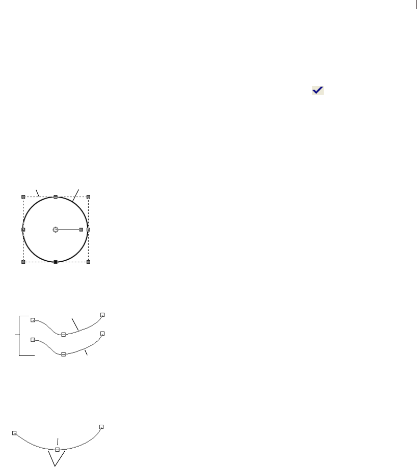
Chapter 13: Drawing and Editing Objects 321
4 Depending on the tool, click and drag, or hold down the left
mouse button and drag to create the object.
5 In the Tool Options palette, click Apply to complete the
creation of the shape and deselect it.
The Anatomy of a Vector Object
Object An object is anything you create with a vector tool. Each
object is represented by its own bounding box. An object has
properties you can control such as line style and fill color. Each
object contains one path made up of contours and nodes.
Path An object contains one path. The path is all the contours in an
object. The properties of the path are controlled by the object’s
properties. A path’s direction flows from its start to end point. Some
paths are closed (their start and end points are the same).
Contour A path contains at least one contour. A contour contains at
least one line segment. A contour’s direction flows from its start to
end point. A contour can also be open or closed. The contours in a
path do not need to be connected. Some of a contour’s properties are
controlled by its object’s properties (e.g. line style, fill color, anti-
aliasing). The shape of a contour is controlled by the type and
location of its nodes.
Node A contour contains at least two nodes. A node is a point on a
contour that define the contour’s shape at that point. For instructions
on editing nodes, see, “Editing Nodes” on page 351.
Line Segment The straight or curved line between two nodes is a line
segment.
Drawing Lines with the Pen Tool
One of the functions of the Pen tool is to draw line segments as well
as connected line segments.
Closed object selected with
Object Selection tool
Open object selected with
Pen tool
Contour selected with
Pen tool
Path
Bounding Box
Path
Contour
Contour
Node
Line Segments
Start
End
Corner Join Types
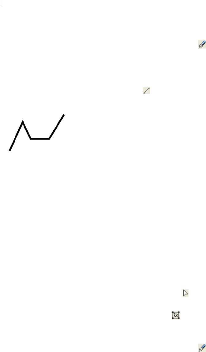
Chapter 13: Drawing and Editing Objects
322
To draw an unconnected line segment:
1 From the Tools toolbar, choose the Pen tool .
2 In the Materials palette, set the desired Foreground/Stroke
property. (Note that for single, unconnected line segments, you
do not need to bother with the Background/Fill color.)
3 In the Tool Options palette's Mode section, click the Draw Lines
and Polylines button .
4 Set other tool options:
Connect Segments: Mark this check box to automatically
connect each line segment.
Show Nodes: Mark this check box to display the objects nodes
during creation.
Create on Vector: Mark this check box to place the object on the
current vector layer. If no vector layer exists, this option will
create a new one for the object. If this option is not checked, the
line will be placed on a raster layer (making it more difficult to
subsequently edit).
Line Style: From the drop-list, choose the style to use for the line.
For a plain, standard line, choose +Solid.
Width: Set the desired line width in pixels.
Anti-alias: Mark this check box to apply anti-aliasing to the
object, giving the edges a smoother appearance.
5 Place the cursor at the starting point, hold down the left mouse
button and then drag the mouse. Release the mouse button when
the line reaches the desired length.
Note: To create a vertical, horizontal, or 45-degree line, hold
down the Shift key while you drag the mouse.
6 In the Tool Options palette, click Apply to complete the creation
of the shape and deselect it.
7 To edit the line, click the Edit button in the Tool Options
palette's Mode section, and then click the line. Edit mode allows
for a variety of ways to modify the line. Note that you can also
choose the Object Selection tool and modify the line in other
ways (such as move, rotate, stretch, etc.).
To draw connected line segments:
1 From the Tools toolbar, choose the Pen tool .
Pen tool line segment
Chapter 13: Drawing and Editing Objects 323
2 In the Materials palette, set the desired Foreground/Stroke
property. If you want the connected segments to have a fill, you'll
also need to set the Background/Fill property. If you do not want
the line segments to have a fill, set the Background/Fill property
to Transparent.
3 In the Tool Options palette's Mode section, click the Draw Lines
and Polylines button .
4 Set other tool options:
Connect Segments: Mark this check box to automatically
connect each line segment.
Show Nodes: Mark this check box to display the objects nodes
during creation.
Create on Vector: Mark this check box to place the object on the
current vector layer. If no vector layer exists, this option will
create a new one for the object. If this option is not checked, the
line will be placed on a raster layer (making it more difficult to
subsequently edit).
Line Style: From the drop-list, choose the style to use for the line.
For a plain, standard line, choose +Solid.
Width: Set the desired line width in pixels.
Anti-alias: Mark this check box to apply anti-aliasing to the
object, giving the edges a smoother appearance.
Join: Choose from one of three Join types. Miter Join (this setting
makes the Miter limit setting available) produces more pointed
joins; Round Join rounds off the joins; and Beveled Join
produces a sloped join.
Miter limit: (This is only available when Miter Join is chosen.)
This sets the degree of pointedness for Miter joins. Lower values
create less pointed joins; higher values created more pointed
joins.
5 Place the cursor at the starting point, hold down the left mouse
button and then drag the mouse. Release the mouse button when
the first line reaches the desired length.
6 To create the next segment, drag the mouse again, and release the
button to complete the next line segment.
7 Repeat step 6 to create as many connected line segments as you
wish.
8 You can complete the shape in two different ways:
Corner Join types
Round Line Bevel
Miter
Chapter 13: Drawing and Editing Objects
324
For an open shape (where the first and last segment are not
connected), click the Create New Contour button in the Tool
Options palette.
For a closed shape (where the first and last segments are
connected), click the Close Contour button in the Tool
Options palette.
Note: To create a vertical, horizontal, or 45-degree line, hold
down the Shift key while you drag the mouse.
9 In the Tool Options palette, click Apply to complete the creation
of the shape and deselect it.
10 To edit the line, click the Edit button in the Tool Options
palette's Mode section, and then click the line. Edit mode allows
for a variety of ways to modify the line. Note that you can also
choose the Object Selection tool and modify the line in other
ways (such as move, rotate, stretch, etc.).
Saving a Preset
Save an often-used set of Tool Options palette settings for
subsequent use as follows:
1 Set the Tool Options to the desired settings.
2 Click the Presets drop-list, and then click the Save preset button
. The Save Preset dialog appears.
3 In the Preset Name field, enter a name for the preset.
4 Optionally, you can click the Options button to enter more
information about the preset, such as the Author, Copyright, and
Description. You can also choose to exclude particular preset
properties by clicking the associated button (a red "x" will appear
over excluded properties).
5 Click OK to save the preset and close the Save Preset dialog.
Loading a Preset
To load a preset, click the Presets drop-list and then click the desired
preset from the list.
Resetting tool options
To reset the Tool Options palette
to the default values, click the
Presets drop-list and then click the
Reset to default button .
Chapter 13: Drawing and Editing Objects 325
Drawing Bezier Curves with the Pen Tool
One of the functions of the Pen tool is to draw Bezier (point to point)
curves.
To draw a Bezier curve object:
1 From the Tools toolbar, choose the Pen tool .
2 In the Materials palette, set the desired Foreground/Stroke
property. This determines the color/material used for the object's
stroke. If you want the curve to have a fill, you'll also need to set
the Background/Fill property. If you do not want the curve to
have a fill, set the Background/Fill property to Transparent.
3 In the Tool Options palette's Mode section, click the Draw Point
to Point - Bezier Curve button .
4 Set other tool options:
Connect Segments: Mark this check box to automatically
connect each curve segment. If you do not mark this check box,
the curve will end after you've placed the second segment.
Show Nodes: Mark this check box to display the objects nodes
during creation.
Create on Vector: Mark this check box to place the object on the
current vector layer. If no vector layer exists, this option will
create a new one for the object. If this option is not checked, the
line will be placed on a raster layer (making it more difficult to
subsequently edit).
Line Style: From the drop-list, choose the style to use for the line.
For a plain, standard line, choose +Solid.
Width: Set the desired line width in pixels.
Anti-alias: Mark this check box to apply anti-aliasing to the
object, giving the edges a smoother appearance.
5 Place the cursor where you want the first node, hold down the left
mouse button and then drag the mouse. As you drag you'll see the
node's control arm handles with the arrow-end of the handle
pointing in the direction you dragged the mouse. Release the
mouse button when the first control arm reaches the desired
length.
6 Place the cursor where you want the second node, and drag the
mouse. As you drag, you'll see the curve segment on the image
canvas.
Pen tool Bezier curve
Chapter 13: Drawing and Editing Objects
326
7 If you checked the Connect Segments option, you can continue
adding segments in this manner.
8 You can complete the Bezier curve object in two different ways:
For an open shape (where the first and last segment are not
connected), click the Create New Contour button in the Tool
Options palette.
For a closed shape (where the first and last segments are
connected), click the Close Contour button in the Tool
Options palette.
9 In the Tool Options palette, click Apply to complete the creation
of the shape and deselect it.
10 To edit the shape, click the Edit button in the Tool Options
palette's Mode section, and then click the shape. Edit mode
allows for a variety of ways to modify the Bezier curve. Note that
you can also choose the Object Selection tool and modify the
shape in other ways (such as move, rotate, stretch, etc.).
Drawing Freehand Curves with the Pen Tool
One of the functions of the Pen tool is to draw Freehand curves.
To draw a Freehand curve object:
1 From the Tools toolbar, choose the Pen tool .
2 In the Materials palette, set the desired Foreground/Stroke
property. This determines the color/material used for the object's
stroke. If you want the curve to have a fill, you'll also need to set
the Background/Fill property. If you do not want the curve to
have a fill, set the Background/Fill property to Transparent.
3 In the Tool Options palette's Mode section, click the Draw
Freehand button .
4 Set other tool options:
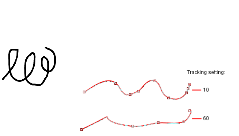
Chapter 13: Drawing and Editing Objects 327
Tracking: (This setting is only available for Freehand mode.)
Tracking sets the distance in pixels between the nodes of a
Freehand curve object. A higher value will create smoother, less
precise lines with fewer nodes. A lower value will create more
segmented, precise lines with more nodes.
Connect Segments: Mark this check box to automatically
connect each Freehand curve object. If you do not mark this
check box, Freehand objects will not be connected.
Show Nodes: Mark this check box to display the objects nodes
during creation.
Create on Vector: Mark this check box to place the object on the
current vector layer. If no vector layer exists, this option will
create a new one for the object. If this option is not checked, the
line will be placed on a raster layer (making it more difficult to
subsequently edit).
Line Style: From the drop-list, choose the style to use for the line.
For a plain, standard line, choose +Solid.
Width: Set the desired line width in pixels.
Anti-alias: Mark this check box to apply anti-aliasing to the
object, giving the edges a smoother appearance.
Join: Choose from one of three Join types. Miter Join (this setting
makes the Miter limit setting available) produces more pointed
joins; Round Join rounds off the joins; and Beveled Join
produces a sloped join.
Miter limit: (This is only available when Miter Join is chosen.)
This sets the degree of pointedness for Miter joins. Lower values
create less pointed joins; higher values created more pointed
joins.
Pen tool Freehand curve
Chapter 13: Drawing and Editing Objects
328
5 Place the cursor where you want to begin the curve, hold down
the left mouse button and then drag the mouse. As you drag
you'll see the curve following the cursor path. Release the mouse
button when you've completed the freehand curve.
6 In the Tool Options palette, click Apply to complete the creation
of the shape and deselect it.
7 To edit the shape, click the Edit button in the Tool Options
palette's Mode section, and then click the shape. Edit mode
allows for a variety of ways to modify the Freehand curve. Note
that you can also choose the Object Selection tool and
modify the shape in other ways (such as move, rotate, stretch,
etc.).
Using the Rectangle Tool
This tool allows you to create squares, rectangles, and rounded
rectangles. To use the tool:
1 Select the Rectangle tool in the Tools toolbar. It's grouped with
the Ellipse, Symmetric Shapes, and Preset Shape tools.
2 In the Materials palette, set your Foreground/Stroke and
Background/Fill properties.
3 In the Tool Options palette's Mode section, choose either Draw
Rectangle or Draw Square .
4 Set the remaining Tool Options:
Show Nodes: mark this check box to display the objects nodes
during creation.
Create on Vector: mark this check box to place the object on the
current vector layer. If no vector layer exists, this option will
create a new one for the object.
Roundness X and Y Radius: sets the radii for the object's corners.
Left, Top, Width, and Height: When the Show Nodes check box is
marked, these settings allow you to determine the object's pixel
coordinates. When Show Nodes is off, these settings become
active when you choose Edit mode after drawing the object.
Line Style options: set the type of line, it's stroke width, anti-alias
setting, as well as Join and Miter Limit settings.
5 Drag the cursor to draw the symmetric object.
6 In the Tool Options palette, click Apply to complete the creation
of the shape and deselect it.
Chapter 13: Drawing and Editing Objects 329
7 To edit the shape, click the Edit button in the Tool Options
palette's Mode section, and then click the shape. Edit mode
allows for a variety of ways to modify the shape. For example,
you can hold down Shift and drag one of the selected rectangle’s
corner handles to maintain equal radii (X and Y will remain the
same). Note that you can also choose the Object Selection tool
and modify the shape in other ways (such as move, rotate,
stretch, etc.).
Using the Ellipse Tool
This tool allows you to create circles and ellipses. To use the tool:
1 Select the Ellipse tool in the Tools toolbar. It's grouped with the
Rectangle, Symmetric Shapes, and Preset Shape tools.
2 In the Materials palette, set your Foreground/Stroke and
Background/Fill properties.
3 In the Tool Options palette's Mode section, choose either Draw
Ellipse or Draw Circle .
4 Set the remaining Tool Options:
Show Nodes: mark this check box to display the objects nodes
during creation.
Create on Vector: mark this check box to place the object on the
current vector layer. If no vector layer exists, this option will
create a new one for the object.
Radius X and Radius Y: When the Show Nodes check box is
marked, these options allow you to set the radii for the object.
When Show Nodes is off, these settings become active when you
choose Edit mode after drawing the object.
Center X and Center Y: When the Show Nodes check box is
marked, these options allow you to determine the object center's
horizontal (Center X) and vertical (Center Y) position. When
Show Nodes is off, these settings become active when you
choose Edit mode after drawing the object.
5 Drag the cursor to draw the ellipse.
6 In the Tool Options palette, click Apply to complete the creation
of the shape and deselect it.
Chapter 13: Drawing and Editing Objects
330
7 To edit the shape, click the Edit button in the Tool Options
palette's Mode section, and then click the shape. Edit mode
allows for a variety of ways to modify the shape. Note that you
can also choose the Object Selection tool and modify the
shape in other ways (such as move, rotate, stretch, etc.).
Using the Symmetric Shape Tool
This tool allows you to create polygons and star shapes. To use the
tool:
1 Select the Symmetric Shape tool in the Tools toolbar. It's
grouped with the Rectangle, Ellipse, and Preset Shape tools.
2 In the Materials palette, set your Foreground/Stroke and
Background/Fill properties.
3 In the Tool Options palette's Mode section, choose either Draw
Polygon or Draw Stellated .
4 Set the remaining Tool Options:
Show Nodes: mark this check box to display the objects nodes
during creation.
Create on Vector: mark this check box to place the object on the
current vector layer. If no vector layer exists, this option will
create a new one for the object.
Number of Sides: sets the number of sides for the object.
Radius: (available only for the Stellated objects) sets the object's
radius.
Rounded Inner: (available only for the Stellated objects) mark
this check box to apply rounded inner corners to the object.
Rounded Outer: mark this check box to apply rounded outer
corners to the object.
Line Style options: set the type of line, it's stroke width, anti-alias
setting, as well as Join and Miter Limit settings.
5 Drag the cursor to draw the symmetric object.
6 In the Tool Options palette, click Apply to complete the creation
of the shape and deselect it.
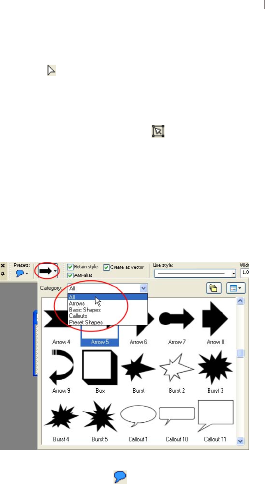
Chapter 13: Drawing and Editing Objects 331
7 To edit the object (assuming you created it as a vector object),
choose Edit in the Tool Options palette's Mode section. Note
that the Symmetric Shape tool's Edit mode functionality is much
like that of the Pen tool's Edit mode functionality. For example,
to add a node to a Symmetric Shape while using the tool's Edit
mode, hold down Ctrl and click on the path. Note that you can
also choose the Object Selection tool and modify the object
in other ways (such as move, rotate, stretch, etc.).
Using the Preset Shape Tool
This tool allows you to place pre-made shapes on the image. The
Shapes drop-list in the Tool Options palette has shape categories.
You can choose to display All shapes, or choose categories such as
Arrows, Basic Shapes, Callouts, and Preset Shapes.
To use the tool:
1 Select the Preset Shape tool in the Tools toolbar. It's grouped
with the Ellipse, Symmetric Shapes, and Preset Shape tools.
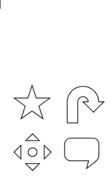
Chapter 13: Drawing and Editing Objects
332
2 In the Tool Options palette's Shapes drop-list (shown above),
choose the desired preset shape. To control what appears in the
drop list, select the appropriate category (All, Arrows, Basic
Shapes, Callouts, or Preset Shapes).
3 To define how the preset shape will appear, choose one of the
following options:
Do not mark the Retain style check box in the Tool Options
palette if you want to define the preset shape's stroke and fill
properties. By having this option unchecked, the preset shape
will be drawn using the current Foreground/Stroke and/or
Backgound/Fill property settings in the Materials palette. If
you do not want to have either a Foreground/Stroke or a
Background/Fill, set the appropriate property to Transparent.
To have the preset shape look just like it does in the Shape list,
mark the Retain style check box. Having this option checked
will ignore the Materials palette settings.
4 Set other tool options:
Create on Vector: Mark this check box to place the object on the
current vector layer. If no vector layer exists, this option will
create a new one for the object. If this option is not checked, the
preset shape will be placed on a raster layer (making it more
difficult to subsequently edit).
Line Style: From the drop-list, choose the style to use for the
preset shape's stroke. For a plain, standard line, choose +Solid.
Width: Set the desired stroke width in pixels.
Anti-alias: Mark this check box to apply anti-aliasing to the
object, giving the edges a smoother appearance.
Join: Choose from one of three Join types. Miter Join (this setting
makes the Miter limit setting available) produces more pointed
joins; Round Join rounds off the joins; and Beveled Join
produces a sloped join.
Miter limit: (This is only available when Miter Join is chosen.)
This sets the degree of pointedness for Miter joins. Lower values
create less pointed joins; higher values created more pointed
joins.
5 Place the cursor on the image canvas, hold down the left mouse
button and then drag to create the shape. Release the mouse
button when the shape reaches the desired size.
Sample preset shapes

Chapter 13: Drawing and Editing Objects 333
Note: To create the shape with the same aspect ratio as that
shown in the Shapes list, hold down Shift while dragging the
mouse. To place the centerpoint of the shape at the position
where you clicked, hold down the right mouse button while
dragging out the shape.
6 In the Tool Options palette, click Apply to complete the creation
of the shape and deselect it.
7 To edit the object (assuming you created it as a vector object),
click the Edit button in the Tool Options palette's Mode
section, and then click the object. Edit mode allows for a variety
of ways to modify the object. Note that you can also choose the
Object Selection tool and modify the object in other ways
(such as move, rotate, stretch, etc.).
Creating New Preset Shapes
You can create your own preset shape by saving any vector object
(lines, shapes, or text) and exporting it for subsequent use with the
Preset Shape tool.
Preset shapes are stored in files called shape libraries, which contain
one or more vector objects. Paint Shop Pro’s default shape libraries
are located in the Preset Shapes folder of the Paint Shop Pro program
folder. By default, your custom preset shapes are saved in the Preset
Shapes folder of your My PSP9 Files folder in your My Documents
folder.
To create a new preset shape:
1 Create an image with one or more vector objects that you want to
save as preset shapes.
2 Give each object a unique name that will help you identify it. You
cannot export multiple objects with the same name. To name
objects, refer to the section Editing Vector Object Properties later
in this chapter.
3 Use the Object Selection tool to select one or more objects to
save as preset shapes. To export all objects, make sure none are
selected.
4 To open the Export Shape Library dialog, do one of the
following:
Choose File > Export > Shape; or

Chapter 13: Drawing and Editing Objects
334
Right-click and choose Export > Shape from the Object
Selection tool's context menu.
5 Type a name for the library file and click OK.
The library file (.PspShape extension) saves to the default Preset
Shapes folder.
To modify a library:
1 Use File > Open to open the library file in Paint Shop Pro.
2 Modify, add, or delete objects in the file.
3 Save and close the library file.
Note: You will have to restart Paint Shop Pro to use the
modified preset objects.
To delete an entire library:
Delete the library file from the Preset Shapes folder.
Creating Custom Line Styles
You can edit the default line styles or design your own line styles.
Saved styles appear in the Line Style drop-down window on the Tool
Options palette for the Pen, Rectangle, Ellipse, Symmetric Shape,
Preset Shape, and Text tools.
To create and save a customized line style:
1 Choose the Pen, Rectangle, Ellipse, Symmetric Shape, Preset
Shape, or Text tool.
2 On the Tool Options palette, click the Line Style drop-down
window.
Note: If you want to copy an existing line style to create a new
style, or if you want to edit or delete an existing line style, select
that style in the Line Style drop-down window.
3 Click the Custom button to open the Styled Lines dialog.
4 In the Caps group box, choose end cap settings for the line
segments. For details, see “End Cap Styles” on page 335.
5 In the Style group box, choose dash and gap lengths. For details,
see “Dash Segment Style” on page 335.
6 When you are finished, do one of the following:
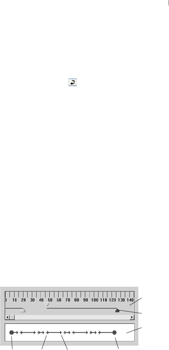
Chapter 13: Drawing and Editing Objects 335
If you are creating a new line, click Save As New. Type a
unique name in the Styled Line Name field. Click OK.
If you are editing an existing line, click Save.
To close the dialog without saving changes, click Cancel.
Note: To reset the dialog back to the style you started with,
click the Reset button .
End Cap Styles
The Caps group box in the Styled Lines dialog controls the end cap
style of each segment in the line style. The settings are:
First Cap From the drop-down list, pick the style for the first
segment in the line.
Size Click this button to open the Cap Size dialog and adjust the size
of the end cap. To set and adjust height and width equally, select the
Link axes check box.
Last Cap From the drop-down list, pick the style for the last segment
in the line.
Different Segment Caps Mark this check box to create separate end
caps for all the middle segments (dashes) in the line. Clear the check
box to use the First Cap and Last Cap settings for each dash.
Segment Start From the drop-down list, pick the style for the
beginning of each dash.
Segment End From the drop-down list, pick the style for the end of
each dash.
Dash Segment Style
The Style group box in the Styled Lines dialog controls the length of
dashes and gaps in the line style.
Preview
Area
Edit
Area
Slider
First Cap Last CapSegment Start Segment End
Chapter 13: Drawing and Editing Objects
336
The Preview Area at the bottom of the Styled Lines dialog displays
the changes you make to the line. The Edit Area has a ruler (in
pixels) to help you to size dashes and gaps. Each dash or gap can be
selected and adjusted with its Slider.
The Style settings are:
Add Adds dashes or gaps. Set the length of the dashes or gaps with
the numeric edit control or by clicking and dragging the sliders.
Delete Deletes the selected dash or gap. Select a dash or gap by
clicking on its slider in the edit area.
Clear Removes all dashes and gaps.
Zoom Buttons Click to zoom the view of the edit area in or
out.
Undo Click to undo previous changes made in the Style group
box.
Editing Vector Object Properties
Drawing lines and shapes as vector objects gives you the flexibility
of editing them after they are drawn.
Note
All of the commands in the Objects menu appear in a context menu
that opens when you right-click on objects, contours, or nodes.
To delete a vector object:
1 Select the vector object to delete.
Note: To delete one object within a group, you must click its
name on the Layers palette.
2 Press the Delete key or choose Edit > Clear.
To edit the colors and materials of vector objects:
1 Select the vector object(s) you want to edit.
2 On the Materials palette, choose a new foreground or background
color or material. The background color controls an object’s fill
color. The foreground color controls an object’s line color.
Selecting vector objects
Use the Object Selection tool to
select vector objects. Press Shift
and to select multiple vector
objects.

Chapter 13: Drawing and Editing Objects 337
Editing Vector Object Properties
Vector properties include the basics of vector objects such as line
width, line style, and anti-aliasing. You can also change the name of
the object (as it appears on the Layers palette) and change whether
the object is visible or not.
To edit vector properties:
1 Select the vector object(s) you want to edit.
2 Click Properties on the Tool Options palette or choose
Objects > Properties to open the Property dialog.
Note: You can also open the dialog by double-clicking the
object’s name on the Layers palette.
3 Choose the line options (stroke width, join, miter, line style, and
anti-alias).
4 Choose stroke (line) and fill settings:
Stroke Clear the check box to choose no line. Mark the check
box and pick a color from the color box to choose line color.
Fill Clear the check box to choose no fill. Mark the check box and
pick a color from the color box to choose fill color.
5 In the Name field, change the name of the object as it appears on
the Layers palette. If more than one object is selected, you must
change their names using the Layers palette.
6 To make the selected object(s) invisible or visible, clear or mark
the Visible check box. (You can also do this by clicking the
Visibility Toggle on the Layers palette.) Invisible objects are
often used as paths for text.
7 Click OK.
Object editing tip
You can also edit a vector object’s
properties by selecting the object
and choosing the Pen tool.
Changing the settings in the Tool
Options palette will modify the
selected object.
Change object names from
the Layers palette
On the Layers palette, right-click
the object name and choose
Rename from the context menu.
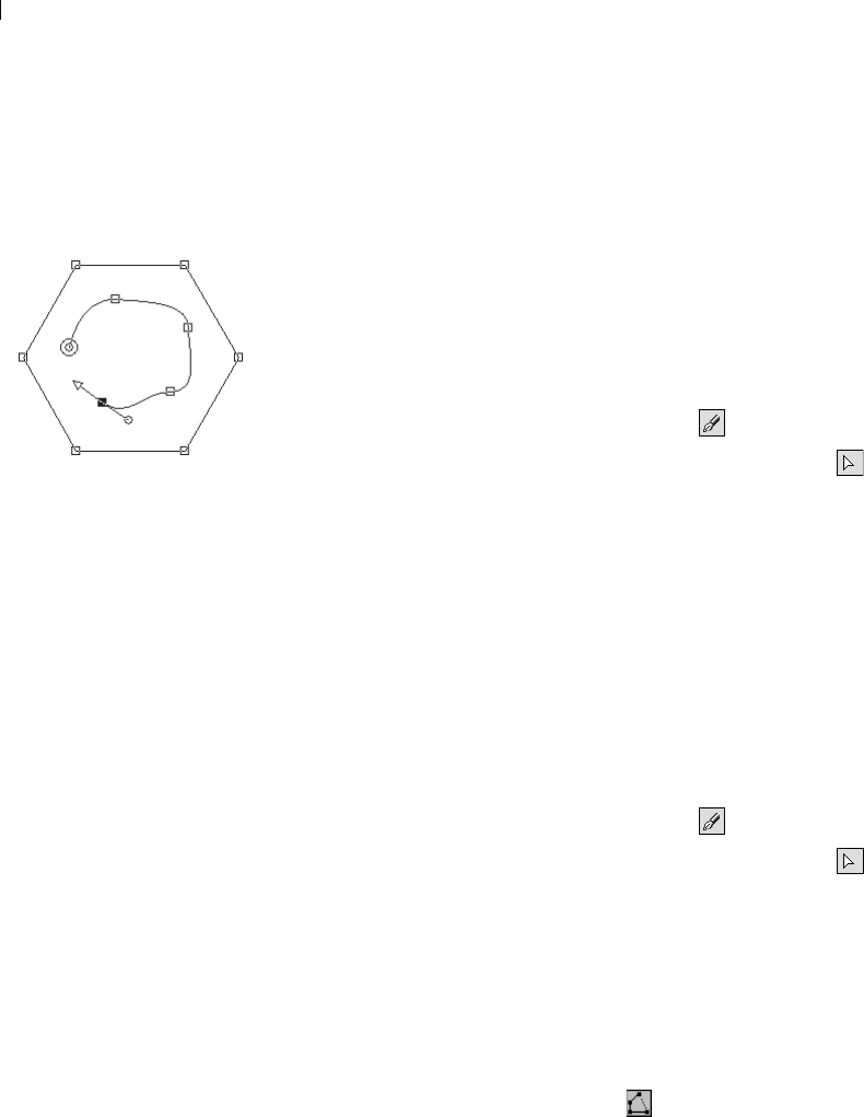
Chapter 13: Drawing and Editing Objects
338
Adding and Closing Contours
You can add new contours to any existing object, even objects you
created with the Preset Shapes tool. The new contour will have the
same properties (including color, material, line style, and so on) as
the selected object.
To add nodes to a contour, see “Adding or Removing Nodes on a
Contour” on page 354.
To add a contour to an object:
1 From the Tools toolbar, select the Pen tool .
2 From the Tool Options palette’s Mode section, click Edit .
3 Click on an object to select it.
4 From the Tool Options palette's Mode section, click the desired
drawing tool (Line, Bezier, or Freehand), and then create the
contour.
5 When you finish drawing the contour, do one of the following:
To continue editing the contour, select Edit Mode from the
Tool Options palette.
To finish this object, choose another tool.
To close a contour:
1 From the Tools toolbar, select the Pen tool .
2 From the Tool Options palette’s Mode section, click Edit .
3 Click on an contour to select it.
4 Do one of the following:
Choose Objects > Edit > Close (Ctrl+Shift+C).
Right-click on the contour and select Edit > Close from the
context menu
On the Tool Options palette, click
Close Selected open contours .
Note: When you close a contour, Paint Shop Pro draws a segment
from the contour’s start to its end node.
Adding a contour
to a preset shape
Another way to add
contours to an object:
You can paste a contour into a
selected contour.
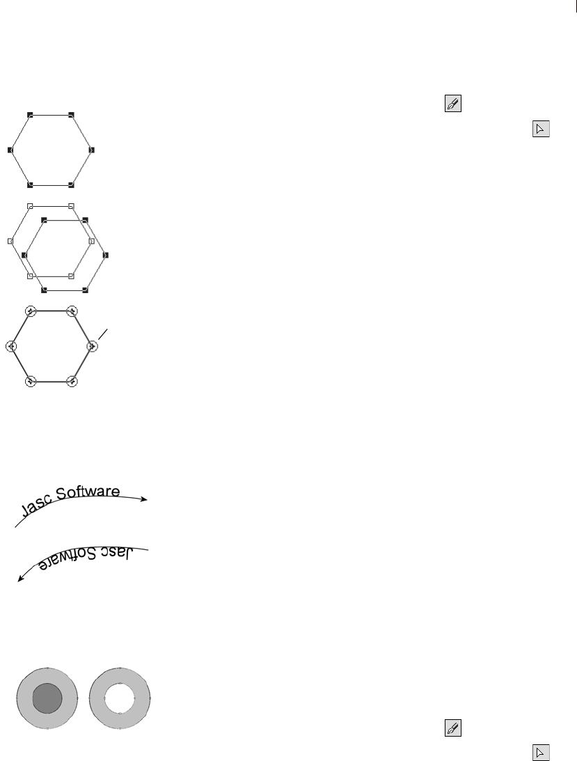
Chapter 13: Drawing and Editing Objects 339
To duplicate a contour:
1 From the Tools toolbar, select the Pen tool .
2 From the Tool Options palette’s Mode section, click Edit .
3 Select one node on the contour.
4 From Objects > Edit choose:
Duplicate (Ctrl+D) Copies the selected contour and pastes it
directly on top of the original contour.
Note: The overlapping nodes will all show node-on-node
indicators.
Duplicate & Offset (Ctrl+Shift+D) Copies the selected contour and
pastes it at an offset from the original contour. The default offset
is 10 pixels in the X and Y directions.
Note: To adjust the number of pixels contours are offset, type
new settings in the Duplication X and Duplication Y fields of the
Tool Options palette.
Reversing the Direction of Contours or Paths
The direction of a contour flows from the start node to the end node.
When you place the cursor over the start node, “START” displays
next to the cursor. When you place the cursor over the end node,
“END” displays. If the object has an closed path, “CLOSE” displays.
For vector objects, you can reverse an entire path (all the contours in
the object) or reverse one contour within a path. The direction of a
contour or a path affects two important things:
Text flow along a contour. Reverse direction to change how text
aligns on a contour.
Fill properties of overlapping contours. When contours with
different directions overlap, the resulting fill is transparent.
Reverse one contour overlapping another contour to create cutout
objects.
To reverse a path or contour:
1 From the Tools toolbar, select the Pen tool .
2 From the Tool Options palette’s Mode section, click Edit .
3 Click on a contour or path, and then select one node on the
contour.
Duplicating a contour
Before
Duplicate
with
Offset
Duplicate
No
Offset
Node on
Node
Reversing a path with text
Reversing a contour to create a
hollow shape

Chapter 13: Drawing and Editing Objects
340
Note: To reverse multiple contours, select one node from each
contour.
4 Right-click on the path or contour, choose Edit from the context
menu, and choose:
Reverse Path (Ctrl + Shift + R) or Reverse Contour (Ctrl+R).
Note: You can also access these commands by choosing
Objects > Edit.
Joining Contours
You can join two contours by connecting their end points.You can
manually drag nodes together to join them, or you can have Paint
Shop Pro automatically join two nodes.
To join two contours:
1 From the Tools toolbar, select the Pen tool .
2 From the Tool Options palette’s Mode section, click Edit .
3 Select one of the contours to show all nodes in the object.
4 Select the start or end node of the first contour you want to join.
Note: You can only join contours in the same object.
5 Do one of the following:
To have Paint Shop Pro draw a contour between the points:
Press Shift and select the start or end node of the other
contour. Press Ctrl + J, or right-click and choose Edit > Join
from the context menu.
To join contours manually:
Click and drag the node over the other contour’s start or end
node. When the cursor displays “JOIN,” release the mouse
button.
To avoid joining contours
when moving nodes:
Hold down Ctrl while you drag.
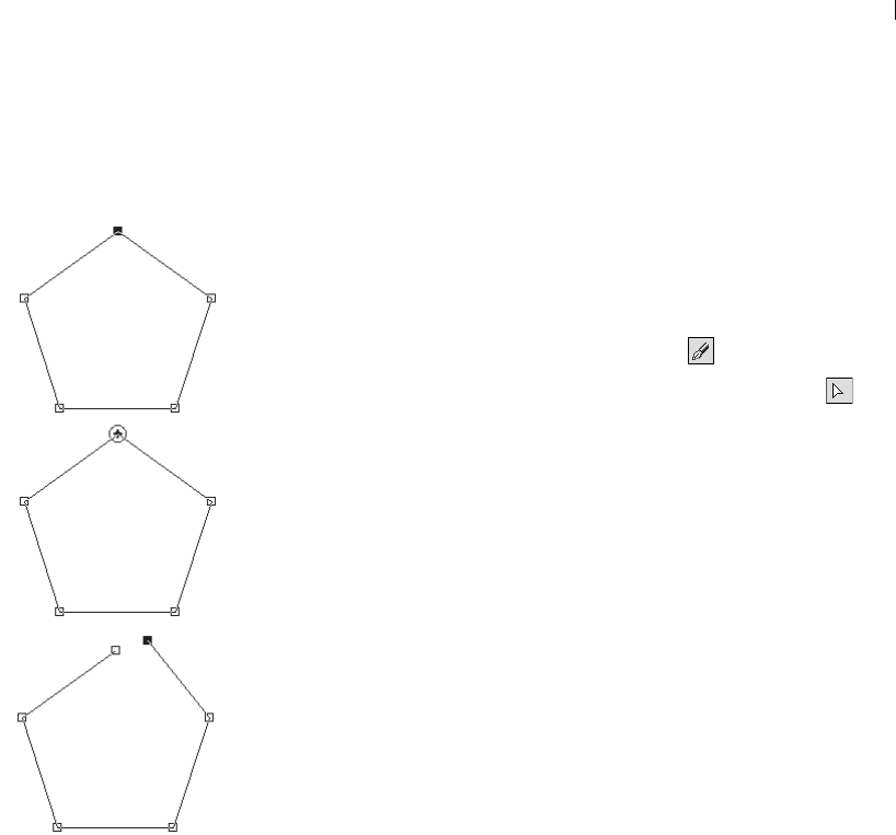
Chapter 13: Drawing and Editing Objects 341
Breaking Contours
You can break a contour at any node. When you break a closed path
or contour, you open it. When you break an open path or contour,
you create two separate contours.
There are two ways to break contours: at a node or with the Pen tool.
To break a contour at a node:
1 From the Tools toolbar, select the Pen tool .
2 From the Tool Options palette’s Mode section, click Edit .
3 Select the node you want to break the contour at.
4 Do one of the following:
Choose Objects > Edit > Break (Ctrl+K).
Right-click the node and choose Edit > Break from the context
menu.
The path or contour breaks and a new node is added on top of the
current node. The node square changes to a node-on-node
indicator. Drag one node away to separate them.
Breaking a contour at a node
Before
After Break
One node
dragged
away
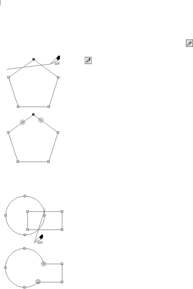
Chapter 13: Drawing and Editing Objects
342
To break a contour with the Pen tool:
1 From the Tools toolbar, select the Pen tool .
2 From the Tool Options palette’s Mode section, click Knife Mode
.
3 Select the contour you want to break.
4 Click and drag across the contour where you want it to break.
Note
The Knife Mode of the Pen tool will cut through all selected
contours in an object.
Breaking contours
with the Pen tool
Breaking multiple contours
with the Pen tool
Cutting in
Knife Mode
After
After
removing cut
sections

Chapter 13: Drawing and Editing Objects 343
Aligning and Arranging Vector Objects
Align and arrange vector objects in a variety of ways: align their
edges, distribute them evenly, center them on the image canvas, and
arrange their order (from top to bottom) on a layer.
Note
All of the commands in the Objects menu appear in a context menu
that opens when you right-click on objects, contours, or nodes.
To move a vector object:
1 Select the object(s) you want to move.
2 Do any of the following:
Click inside a bounding box and drag the object or objects to a
new position.
To move one pixel at a time, press Shift or Ctrl and press the
Up, Down, Left, or Right arrow keys.
To move 10 pixels at a time, press Ctrl + Shift and press the
Up, Down, Left, or Right arrow keys.
Grouping and Ungrouping Vector Objects
To edit several objects in similar ways, group them together. When
objects are grouped, you can move, resize, reshape, and change their
lines and materials all at once. You can also group several groups of
vector objects.
When you group objects on different layers, Paint Shop Pro
automatically moves them all to the layer of the first object you
selected.
Each group has a label on the Layers palette and all the objects in the
group are shown as components. Click the plus sign in front of the
group name to show the group’s components.
Note
Even if an object belongs to a group, you can still select it on the
Layers palette and edit it individually.
There are two ways to group objects: Use the Object Selection tool
or use the Layers palette.
Copying, and pasting vector
objects
Cut, copy, and paste vector objects
just like any other data. Select the
object and from the Edit menu,
select Cut or Copy.
To paste vector objects within the
same layer, choose Edit > Paste >
As New Vector Selection.
To paste vector objects as a new
layer, choose Edit > Paste >
As New Layer.
To paste vector objects as a new
image, choose Edit > Paste >
As New Image.
Chapter 13: Drawing and Editing Objects
344
To group vector objects using the Object Selection tool:
1 Use the Object Selection tool to select each object you want in
the group.
2 On the Tool Options palette, click Group or choose Objects >
Group.
To group objects using the Layers palette:
1 On the Layers palette, click the name of the first object you want
to group.
2 Press Shift and click each object you want to add to group.
3 Right-click one of the object names and choose Group from the
context menu.
Note: If you group objects from several layers, Paint Shop Pro
moves them all to the layer of the first object you selected.
To ungroup all objects in a group:
1 Select the group.
2 Do one of the following:
Choose Objects > Ungroup.
On the Object Selection tool’s Tool Options palette, click the
Ungroup button .
On the Layers palette, right-click the group name and select
Ungroup from the context menu.
To remove a single object from a group:
On the Layers palette, drag the object from the group into another
group or layer.
How to edit one object
within a group
When you have a group of objects,
most Paint Shop Pro commands
apply to the entire group. However,
there are several ways to edit one
object within the group. First, click
the object name on the Layers
palette (the name becomes bold),
then you can:
Right-click the object name and
choose a command from the
context menu.
Move the object using the arrow
keys.
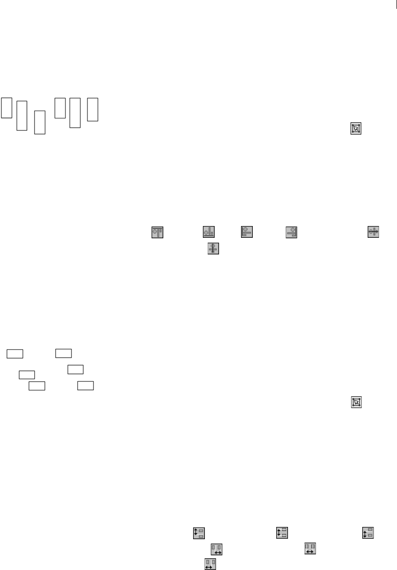
Chapter 13: Drawing and Editing Objects 345
Aligning Vector Objects
You can align objects in relation to each other. For example, align
their top edges.
To align vector objects:
1 On the Tools toolbar, choose the Object Selection tool .
2 Select the first vector object. All other objects selected will align
to this object.
3 Press the Shift key and select each additional object you want to
align.
4 On the Tool Options palette, click one of the Object Alignment
buttons:
Top , Bottom , Left , Right , Vertical Center , or
Horizontal Center .
Note: You can also choose Objects > Align and select a
command.
Distributing Vector Objects
You can evenly distribute vector objects in relation to each other. For
example, distribute three objects so that their top edges are evenly
spaced from each other. To distribute objects in relation to the
canvas, see “Positioning Vector Objects on the Canvas” on page 346.
To evenly distribute objects:
1 On the Tools toolbar, choose the Object Selection tool .
2 Select one object to select it. Press Shift and select the other
objects.
Note: You must have three or more objects selected to distribute
them in relation to each other.
3 Choose from the following:
To distribute objects in relation to each other:
On the Tool Options palette click one of the Object
Distribution buttons:
Vertical Top , Vertical Center , Vertical Bottom ,
Horizontal Right , Horizontal Center , or
Horizontal Left .
Align Tops
Before After
Distribute Vertical Tops
Before After
Another way to distribute
With your objects selected, right-
click on an object. From the
context menu, select a distribution
method from Distribute Object.
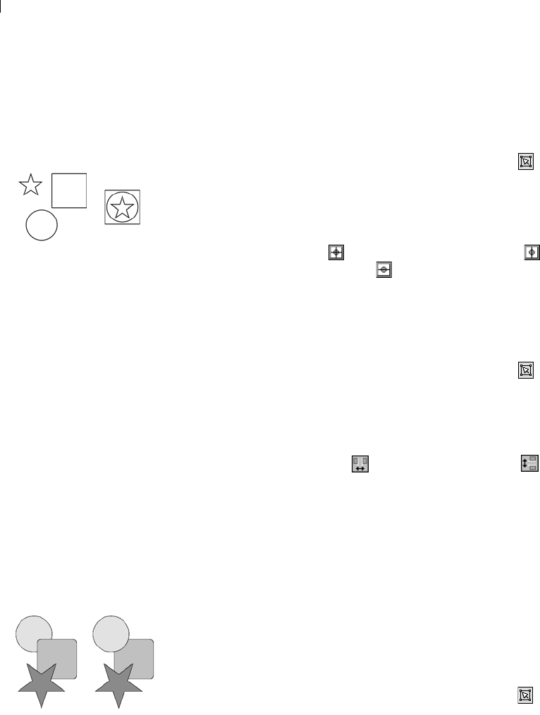
Chapter 13: Drawing and Editing Objects
346
Positioning Vector Objects on the
Canvas
To align vector objects to the canvas:
1 On the Tools toolbar, choose the Object Selection tool .
2 Click an object to select it.
3 On the Tool Options palette, click one of the Position on Canvas
buttons:
Center in Canvas , Horizontal Center in Canvas , or
Vertical Center in Canvas .
Note: All these commands are also available by choosing
Object > Align.
To distribute vector objects on the canvas:
1 On the Tools toolbar, choose the Object Selection tool .
2 Click an object to select it.
3 On the Tool Options palette, click one of the Position on Canvas
buttons:
Space Evenly Horizontal or Space Evenly Vertical .
Note: All these commands are also available by choosing
Object > Distribute.
Arranging Vector Objects
Each object you draw on a layer is stacked on top of the next (even if
they don’t overlap). If you draw 50 objects on a layer, the 50th is at
the top and the 1st in on the bottom. When you have overlapping
objects, you can move objects up or down the stack of objects.
To arrange vector objects:
1 On the Tools toolbar, choose the Object Selection tool .
2 Click an object to select it.
Center on Canvas
Before After
Bringing the circle to the top
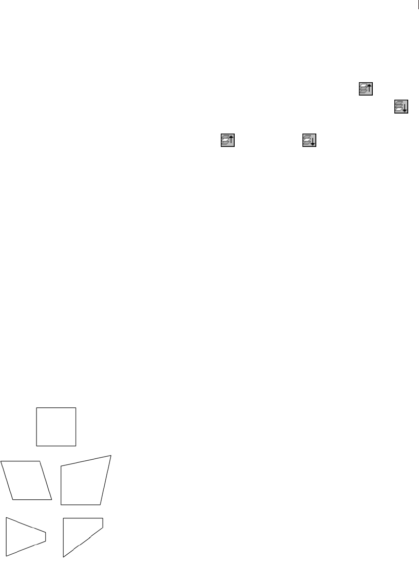
Chapter 13: Drawing and Editing Objects 347
3 Do one of the following:
To move an object to the top:
On the Tool Options palette, click Bring to Top .
To move an object to the bottom: Click Send to Bottom .
To move an object up or down one position:
Click Move Up or Move Down .
Note: All these commands are also available by choosing
Objects > Arrange.
Resizing and Reshaping Vector Objects
The Object Selection tool gives you the power to transform vector
objects and vector text interactively. Select an object and drag the
handles on the bounding box to resize, rotate, shear, distort, or apply
perspective. You can also resize and reshape a vector object by
editing its nodes and contours using the Pen tool. For instructions,
see “Editing Paths and Contours” on page 349.
Note
All of the commands in the Objects menu appear in a context menu
that opens when you right-click on objects, contours, or nodes.
To resize and reshape vector objects:
1 Use the Object Selection, Preset Shape, or Text tool to select an
object.
2 Do one or more of the following:
To resize, click and drag one of the corner or edge handles.
To resize while keeping the current proportions, right-click
and drag a corner handle.
To change perspective symmetrically, press Ctrl and drag a
corner handle horizontally or vertically.
To change perspective asymmetrically, press Shift and drag a
corner handle.
To shear, press Shift while dragging a side handle.
To distort, press Ctrl and Shift while dragging a handle.
Using the Layers palette to
arrange vector objects
To change an object’s position on a
layer: select the object name in the
Layers palette, click and drag the
object up or down in the list of
objects.
Quick steps for
proportional scaling
To resize a vector object and keep
the same proportions, select the
object with the Object Selection
tool and right-click and drag a
corner handle of the bounding box.
Reshaping Objects
Before
Shear Distort
Symmetric
Perspective Asymmetric
Perspective
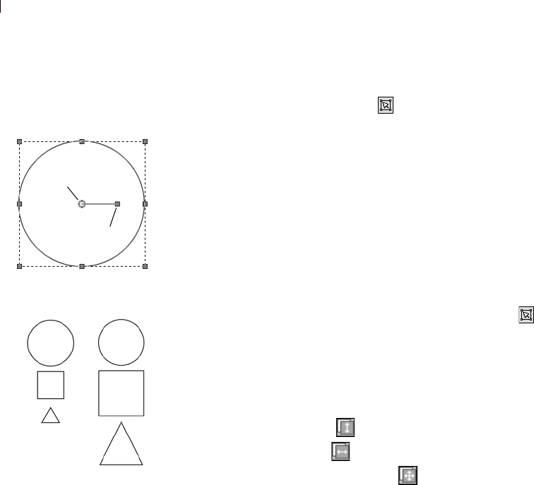
Chapter 13: Drawing and Editing Objects
348
To rotate vector objects:
1 Use the Object Selection tool to select an object.
2 Click and drag the rotation handle.
Note: To change the center of rotation, press Ctrl while clicking
and dragging the rotation pivot point to a new location.
Making Vector Objects the Same Size
You can make all objects you select the same height, width, or both.
The dimensions of the first object selected are used for resizing.
To make vector objects the same size:
1 On the Tools toolbar, choose the Object Selection tool .
2 Click the first vector object. The first object controls how all the
other selections will be resized.
3 Press the Shift key and click the objects that you want to resize.
4 On the Tool Options palette, choose a Make Same Size option:
Make Same Height
Make Same Width
Make Same Width and Height
Note: All these commands are also available by choosing
Objects > Make Same Size.
Rotation Controls
Same Size Both
Rotation Pivot
Point
Rotation Handle
Before
After
Chapter 13: Drawing and Editing Objects 349
Editing Paths and Contours
To fine-tune or completely transform vector objects, edit their nodes,
contours, and paths. For more detail on paths and contours see, “The
Anatomy of a Vector Object” on page 321. For more detail on types
of nodes, see “Editing Nodes” on page 351.
Note
All of the commands in the Objects menu appear in a context menu
that opens when you right-click on objects, contours, or nodes.
To edit a contour:
1 From the Tools toolbar, select the Pen tool .
2 From the Tool Options palette's Mode section, select Edit .
3 Click on a contour, then double-click one node to select all
nodes.
4 Choose Objects > Edit and select a command:
Cut Removes the selected contour to the Windows clipboard. If
the object has only one contour, the command removes the entire
object.
Copy Copies the selected contour to the Windows clipboard.
Paste Pastes a cut or copied contour into the current object.
Delete Deletes the selected contour.
Select All (Ctrl+A) Selects all nodes in the path.
Select None (Ctrl+Shift+A) Deselects any selected nodes.
Invert Selection (Ctrl+I) Selects all deselected nodes and
deselects all selected nodes.
To delete a contour:
1 From the Tools toolbar, select the Pen tool .
2 From the Tool Options palette's Mode section, select Edit .
3 Click on a contour, then double-click one node to select all
nodes.
4 Press Delete or choose Edit > Clear.
Note: You cannot delete a path. A path is deleted with its object
or when all its contours are deleted.

Chapter 13: Drawing and Editing Objects
350
To move a path:
1 From the Tools toolbar, select the Pen tool .
2 From the Tool Options palette's Mode section, select Edit .
3 To select the path, click on any contour in the path.
4 To move all the contours in the object (the path), click and drag
any contour.
To move a contour:
1 From the Tools toolbar, select the Pen tool .
2 From the Tool Options palette's Mode section, select Edit .
3 Do one of the following:
Hold down Shift and move the cursor over the contour. The
cursor will display “SUB.” Click and drag the contour.
Click on a contour or path, then double-click one node to
select all nodes. Click and drag one of the nodes.
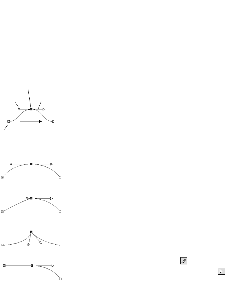
Chapter 13: Drawing and Editing Objects 351
Editing Nodes
The Anatomy of a Node
A node is a point on a contour that defines the contour’s shape at that
point. The Nodes have zero, one, or two control arms extending from
them. The length and direction of the control arms determine the
shape of the contour at the node. Click on the control handles to
adjust control arms. The straight or curved line between two nodes is
a line segment.
Node Types
Symmetrical Choose this type to create a smooth flowing curve from
one side of the node to the other. Any adjustments to one control arm
are mirrored by the other.
Asymmetrical Choose this type to obtain a different amount of curve
on each side of the node, but still keep a smooth flow through the
node. You can independently adjust the length of each control arm,
but the not the direction.
Cusp Choose this type for nodes that have extreme changes in
direction. You can adjust the length and direction of each control
arm independently.
Smooth Choose this type of node to create a smooth transition
between straight and curved line segments.
Selecting Nodes
To select one or more nodes:
1 From the Tools toolbar, select the Pen tool .
2 From the Tool Options palette's Mode section, select Edit .
3 Click a vector object. The object becomes an outline with nodes.
4 Do any of the following:
To select one node, click the node.
To deselect a node, press shift click the node.
To select multiple nodes, press Shift and click each node. Or,
click and drag a rectangle over the nodes.
Components of a Node
Symmetrical Node
Asymmetrical Node
Cusp Node
Smooth Node
Selected Node
Deselected
Node
Control
arm
Control
Handle
Direction

Chapter 13: Drawing and Editing Objects
352
To select all nodes on a contour, double-click one node. If the
object has only one contour, this selects all nodes in the path.
To select all nodes in a path (all nodes in the object), press
Ctrl + A or right-click and choose Edit > Select All from the
context menu.
To select the next or previous node on a contour, press Shift
and press an arrow key.
Note: Start or end nodes are easy to find. The cursor will display
“START,” “END” when it is over the node. If the shape is closed,
the cursor will display “CLOSE.”
Moving Nodes
Moving a node alters the shape of a vector object. If an object has
more than one contour, move a contour by moving all of its nodes.
Move the path to move the entire object.
To move a node:
1 From the Tools toolbar, select the Pen tool .
2 From the Tool Options palette's Mode section, select Edit .
3 Click and drag a node to a new position or press the arrow keys.
Note: To move multiple nodes, select them and click and drag a
selected node.
Changing Curves and Lines
You can adjust the shape of the contour at a node by changing the
node type, adjusting the node’s control arms or changing the line
segments.
Node moving tips:
While you drag a node you can
constrain its line segments to 45
degree increments.
Hold down Shift to constrain the
previous segment.
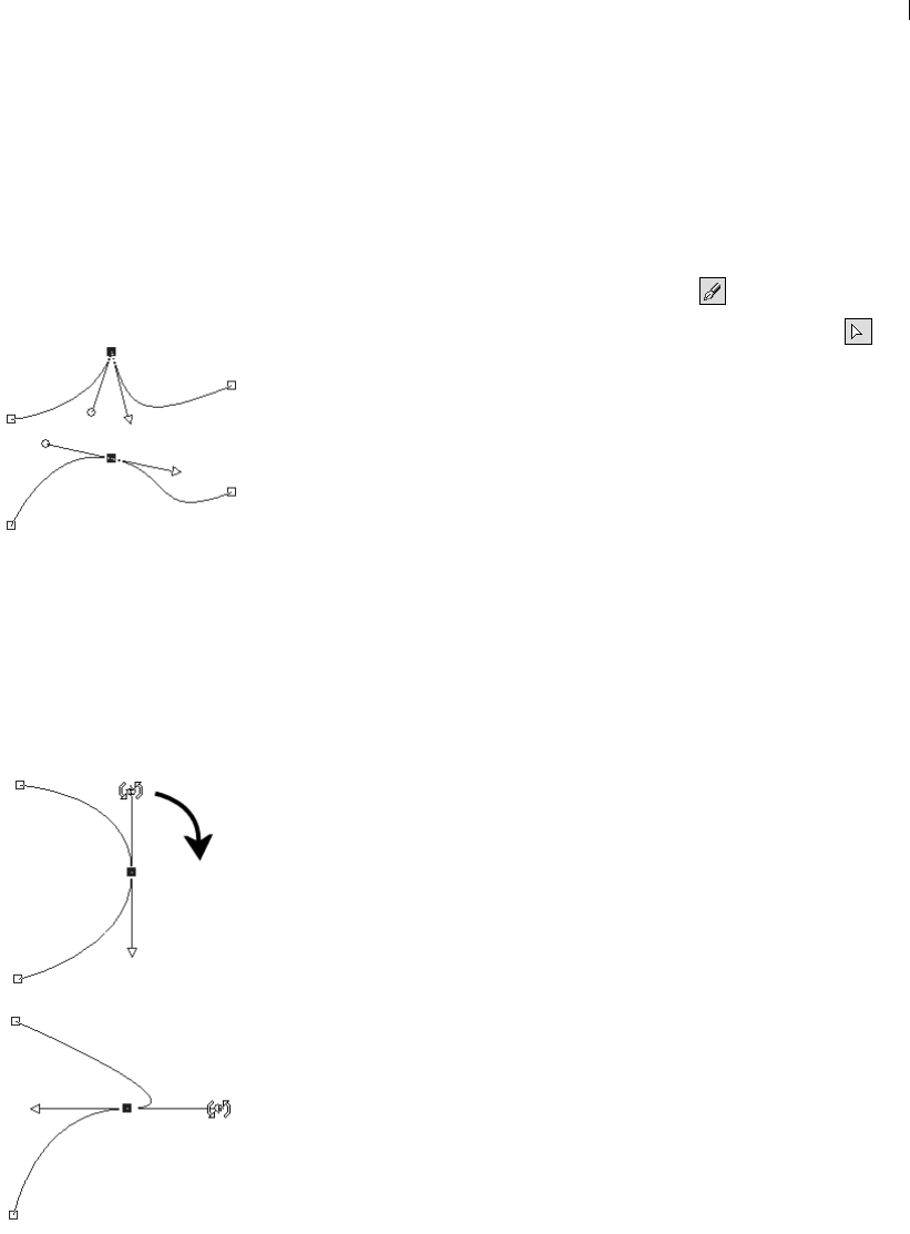
Chapter 13: Drawing and Editing Objects 353
Changing Node Types
For example, to soften a sharp corner, change a cusp node to a
symmetrical node.
To adjust a curve by changing the node type:
1 From the Tools toolbar, select the Pen tool .
2 From the Tool Options palette's Mode section, select Edit .
3 Select a node.
4 Do one of the following:
Choose Objects > Node Type and select a node type:
Asymmetrical (Ctrl+Shift+S)
Symmetrical (Ctrl+S)
Cusp (Ctrl+U)
Smooth
Right-click on the node, choose a Node Type from the context
menu.
Adjusting Nodes with Control Arms
The length and direction of a nodes control arms determines the
shape of the contour at the node. The arrow control handle indicates
the direction of the contour.
To adjust a curve using control arms:
1 Select a node to display its control arms.
Note: Cusp nodes may have no control arms.
2 Move the cursor over a control handle until the cursor changes to
two rotating arrows, and then click and drag the handle.
Note: To constrain the control arms to fixed angles (45 degree
increments), press and hold Shift as you drag.
Changing Line Segments
Instead of changing node types, you can simply tell Paint Shop Pro
what type of line segment you want on each side of the node. You
can also convert line segments from curved to straight. The line
segment type and node type work together. For example, when you
add a straight line before or after a symmetrical curve, the node type
changes to asymmetrical.
From Cusp to Symmetrical
Adjusting Control Arms
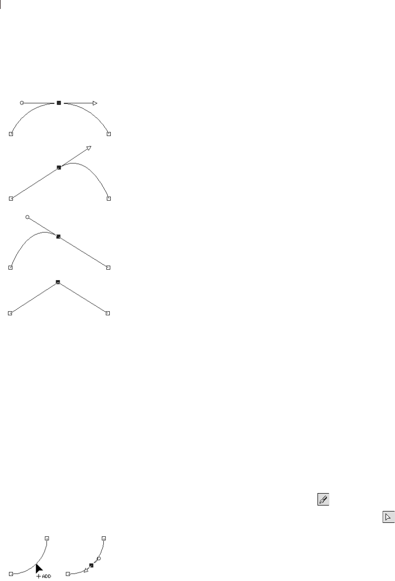
Chapter 13: Drawing and Editing Objects
354
To change the line segment before or after a node:
1 Select a node.
2 Do one of the following:
Choose Objects > Node Type and select an option:
To straighten the segment before and after a node, choose
Convert to Line. (Ctrl+L).
To straighten the segment before or after a node, choose Line
Before (Ctrl+B) or Line After (Ctrl+F).
To curve the segment before or after a node, choose Curve
Before (Ctrl+1) or Curve After (Ctrl+2).
Right-click the node and choose a Node Type from the context
menu.
3 Make a selection:
Note: You can also access these commands by choosing
Objects > Node Type.
To straighten a curve between two nodes:
1 Select two consecutive nodes.
2 Right-click one node and choose Node Type >Convert to Line
from the context menu.
Adding or Removing Nodes on a
Contour
To create more options for editing the shape of a vector object, add,
delete, or merge nodes anywhere along the path of a vector object.
Adding Nodes
You can add nodes in all three modes of the Pen tool.
To add nodes on a contour (Drawing and Edit Modes):
1 From the Tools toolbar, select the Pen tool .
2 From the Tool Options palette's Mode section, select Edit .
3 Click the contour you want modify.
4 Press and hold Ctrl as you move the cursor over the contour to
where you want to add a node. The cursor displays “+ADD.”
Changing Line Segments
Original
Line Before
Line After
Convert to Line
Adding Nodes in
Drawing or Edit Modes
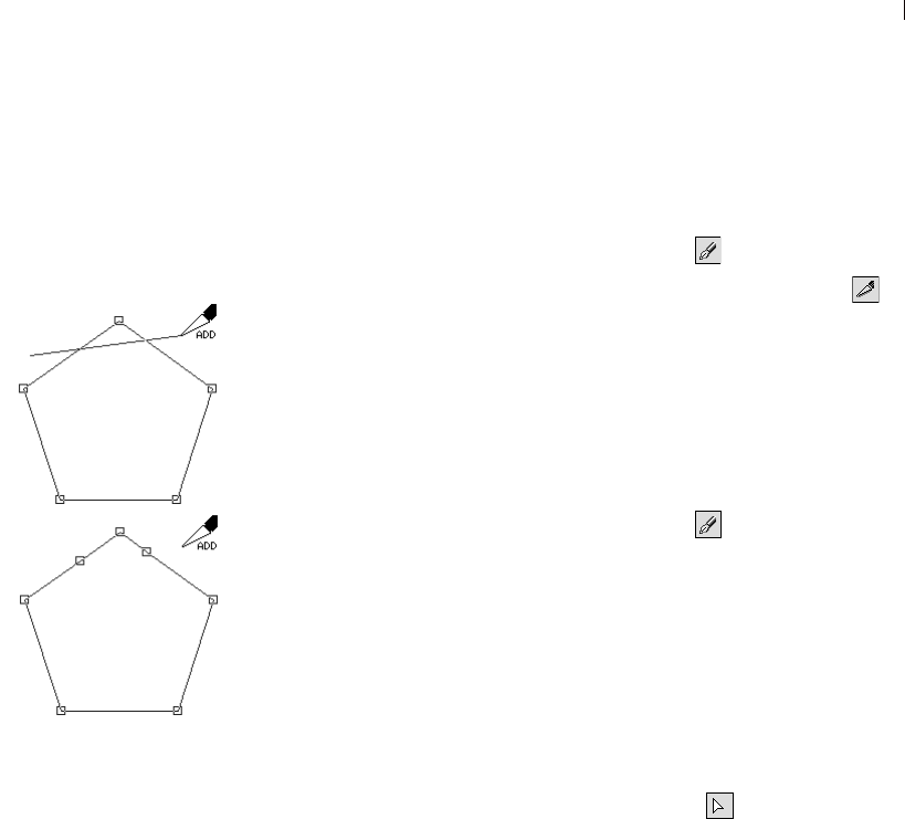
Chapter 13: Drawing and Editing Objects 355
5 While continuing to press Ctrl, click the line. A symmetric node
is added.
To add nodes on a contour (Knife Mode):
1 From the Tools toolbar, select the Pen tool .
2 From the Tool Options palette's Mode section, select Knife .
3 Click the contour you want modify.
4 Press and hold Ctrl. The cursor changes from “CUT” to “ADD.”
5 Click and drag the cursor across the contour where you want to
add nodes.
To add a new start or end node:
1 From the Tools toolbar, select the Pen tool .
2 From the Tool Options palette, select the egment type you want
to use (Line, Bezier, or Freehand).
3 Select the start or end node of the contour.
4 Click to draw another node, the contour automatically connects
to the new node.
5 Do one of the following:
Continue drawing new nodes.
To edit the nodes or contour, select Edit .
To finish the changes, choose another tool.
Adding nodes in Knife Mode
Click and
drag to add
nodes
After
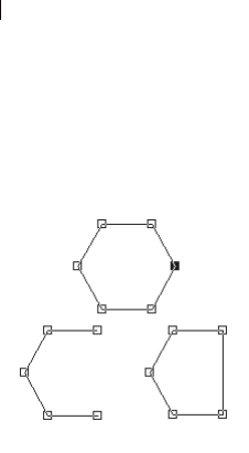
Chapter 13: Drawing and Editing Objects
356
Deleting or Merging Nodes
Merging nodes on a contour removes the nodes from the contour, but
retains the line segments on each side. The line segments are
combined into one line segment between remaining nodes. If the
contour is curved at the node, Paint Shop Pro attempts to retain the
curve.
Deleting a node on a contour removes the node and line segments on
each side. If you delete a node in the middle of an open contour, the
vector object becomes two separate contours. If you delete a node in
a closed contour, the contour opens.
To merge one or more nodes:.
1 Select the node you want to merge.
2 Merge the node in one of these ways:.
Choose Objects > Edit > Merge (Ctrl + M).
Right-click on the node and choose Edit > Merge from the
context menu.
Press Ctrl, move the cursor over the node until “MERGE”
displays, and then click the node.
To delete a node and its line segments:
1 Select the node you want to delete.
2 Do one of the following:
Press Delete.
Right-click and choose Edit > Delete from the context menu.
Choose Objects > Edit > Delete.
Note: To delete one line segment, break the path at one node of
the line segment, and then delete the new node that is created.
For information on breaking paths, see “Breaking Contours” on
page 341.
Deleting vs. Merging
Node
Deleted Merged
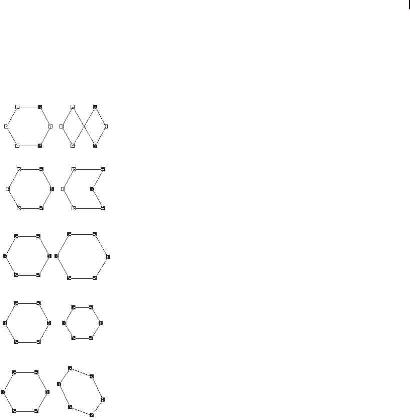
Chapter 13: Drawing and Editing Objects 357
Transforming Nodes
You can change the shape of a contour by manipulating its nodes in a
variety of ways, such as flipping, mirroring, and rotating.
Transform nodes using the Object menu commands or the Tool
Options palette.
Using the Object Menu to Transform Nodes
The Objects menu will transform selected nodes using the current
settings for each transformation command.
To transform nodes with the current settings:
1 Select the nodes you want to transform.
2 Choose Objects > Transform Selected Nodes and choose a
command:
Flip (Ctrl+Shift+F) Moves selected nodes along the vertical
axis—those on top go the bottom and vice versa. Applied to a
single node, the control arms (if any) will flip.
Mirror (Ctrl+Shift+M) Moves selected nodes along the horizontal
axis—those on the left go to the right and vice versa. Applied to a
single node, the control arms (if any) will mirror.
Rotate Rotates the selected nodes by the current rotation setting.
Applied to a single node, the control arms (if any) will rotate.
Skew X Moves selected nodes to the left or right (along the
horizontal axis) using the current skew setting.
Skew Y Moves selected nodes to the left or right (along the
vertical axis) using the current skew setting.
Contract (F8) Moves the selected nodes closer to each other by
the current contraction setting. Cannot be applied to a single
node.
Expand (F9) Moves the selected nodes away from each other by
the current expansion setting. Cannot be applied to a single node.
Transforming Nodes
Mirror
Flip
Expand
Contract
Skew Y
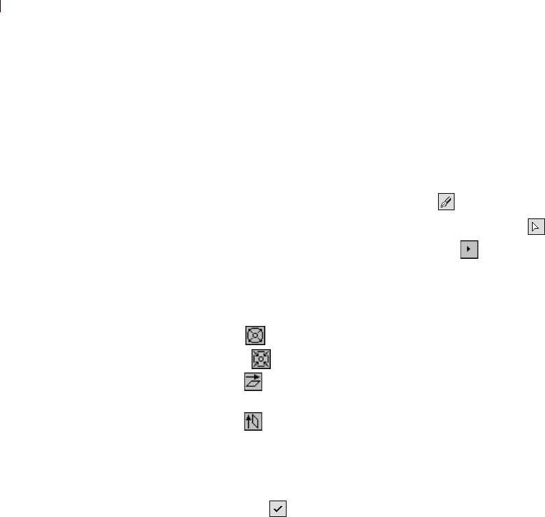
Chapter 13: Drawing and Editing Objects
358
Using the Tool Options Palette to Transform
Nodes
You can set and apply transformations to selected nodes from the
Pen tool’s Tool Options palette.
To adjust and apply transformation settings:
1 From the Tools toolbar, select the Pen tool .
2 From the Tool Options palette's Mode section, select Edit .
Note: You may need to click the More button to view all the
options in the Tool Options palette.
3 Select the node(s) to transform.
4 From the Tool Options palette select a transform function:
Expand Sets the number of pixels to expand nodes.
Contract Sets the number of pixels to contract nodes.
Skew X Sets the number of pixels to skew nodes on the
horizontal axis.
Skew Y Sets the number of pixels to skew nodes on the
vertical axis.
Rotate Sets the degrees nodes will rotate.
5 Type a value for the selected transformation setting.
6 Click Apply .

359
Working with Layers
Layers are fundamental to creating and editing images in
Paint Shop Pro. Use layers to add elements to your images, create
artistic effects and illustrations, and make editing images easier. You
can add or delete layers, rearrange their stacking order (the order
from top to bottom), and blend their pixels in a variety of ways.
Unless you merge the layers, each layer remains independent; you
can edit it without affecting the others.
Contents About Layers. . . . . . . . . . . . . . . . . . . . . . . . . . . . . . . . . . . . . . 360
Adding New Layers to Images . . . . . . . . . . . . . . . . . . . . . . . . . 366
Editing Layer Properties . . . . . . . . . . . . . . . . . . . . . . . . . . . . . 368
Modifying Layers. . . . . . . . . . . . . . . . . . . . . . . . . . . . . . . . . . . 378
Using Adjustment Layers . . . . . . . . . . . . . . . . . . . . . . . . . . . . . 382
Using the Layers palette . . . . . . . . . . . . . . . . . . . . . . . . . . . . . 385
CHAPTER 14
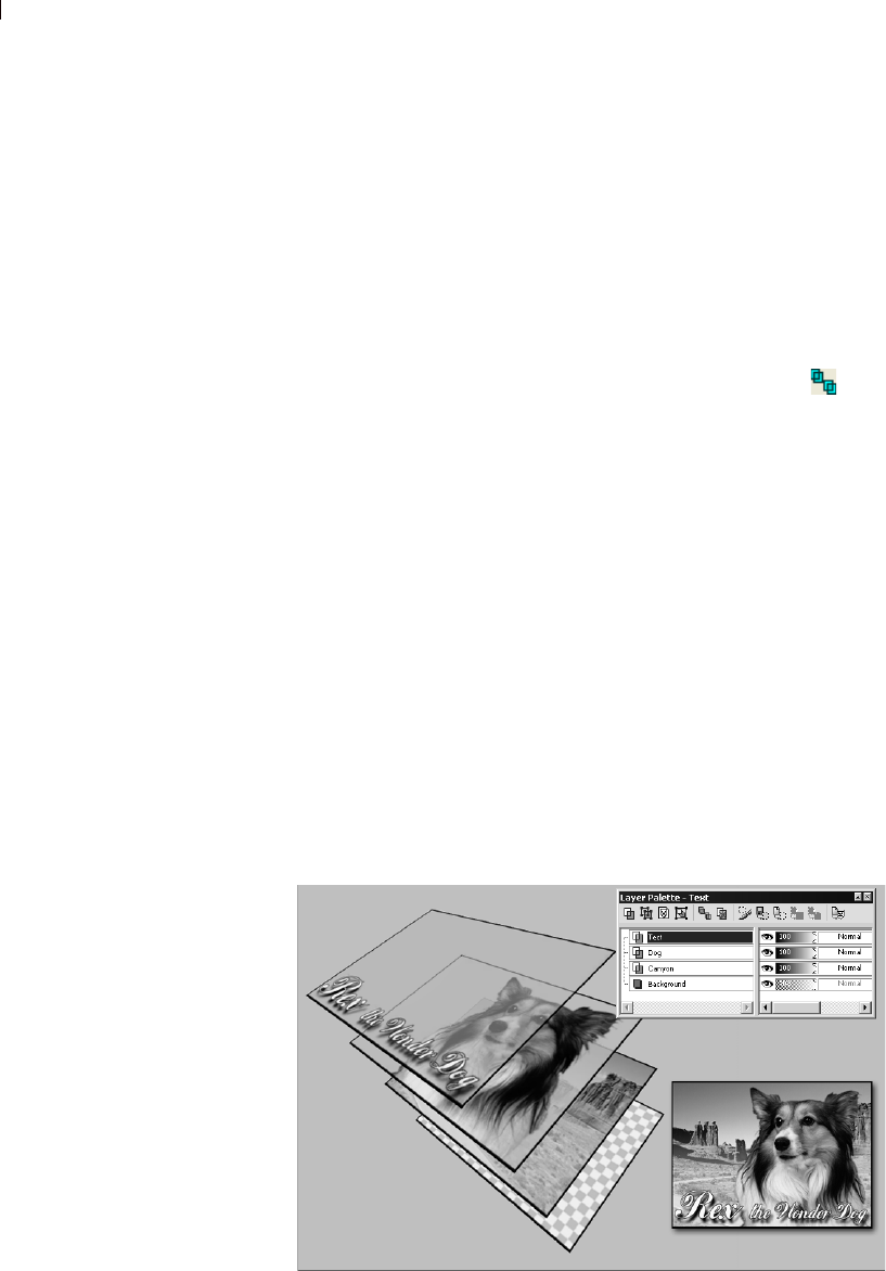
Chapter 14: Working with Layers
360
About Layers
When you create or import an image in Paint Shop Pro, the image
has a single layer. Depending on the type of image you created or
imported, you'll see in the Layers palette that the single layer may be
labeled Background (this is case when opening images such as
photos or screen captures), Raster, Vector, or Art Media.
For most simple image retouches and corrections, you do not have to
add any layers. However, it's generally a good habit to simply
duplicate the layer (by clicking the Duplicate Layer button in the
Layers palette toolbar) before applying actions such as the photo
correction commands. By applying any changes to the duplicated
layer, you'll always preserve the original image on its own layer.
And when you intend to do more complex work such as add
elements to the image, create photo compassions, add text and other
effects, etc., it's highly encouraged that you utilize layers for these
tasks.
Each layer that you add begins as a transparent sheet over the
background. As you add brush strokes, vector objects, or text, you
cover up parts of the Background layer. Transparent parts allow you
to see through to underlying layers. You can stack up multiple layers
to create whatever effect you’d like—such as artistic compositions,
photo collages, or complex illustrations.
In the following illustration, each image is on a separate layer. The
background layer is transparent.
Ways to use layers
For descriptions of the many tasks
you can accomplish with layers,
check out these sections:
“Using Layers with Photographic
Images” on page 364
“Using Layers with Illustrations”
on page 365
Creating image compositions with layers

Chapter 14: Working with Layers 361
Types of Layers
There are six types of layers: Background, Raster, Vector, Art
Media, Mask, and Adjustment. The icon before the layer name on
the Layers palette shows the type of layer. In addition, you can
create layer groups, and promote selections to layers. Paint Shop Pro
supports up to 500 layers. The actual number of layers allowed in an
image may be limited by the amount of memory in your computer
Note: Only greyscale and 16 million color images can have
multiple raster layers. Images of any color depth can include
multiple vector layers.
Background Layer
The background layer is the bottom layer of an image. It is
named “Background” on the Layers palette and cannot be renamed.
When you import file formats such as JPEG, GIF, or PNG into
Paint Shop Pro, they are one layer—the background layer.
The background layer contains raster data but cannot display
transparency. You cannot change its order in the stack, its blend
mode, or its opacity.
To move a background layer higher in the stacking order, promote it
to a regular raster layer; see “Promoting a Background Layer to a
Regular Raster Layer” on page 367.
If you create a new image with a transparent background, it does not
have a background layer and its bottom layer is a raster layer named
“Raster Layer 1”. You may move this layer anywhere within the
stacking order, or change its opacity or blend mode.
Raster Layers
Raster layers are layers with raster data only. Raster data is
composed of individual elements, called pixels, arranged in a grid.
Each pixel has a specific location and color. Photographic images
are composed of raster data. If you magnify raster data, you can see
the individual pixels as squares of colors.
Use raster layers for displaying subtle changes in tones and colors.
Or, use raster layers for objects and raster text on which you want to
apply raster-only commands and tools. The effects commands, the
painting tools, and many other tools apply only to raster layers.
Raster and vector data
For more information on raster and
vector data, see “About Raster and
Vector Graphics” on page 35.
Background layer or not?
Paint Shop Pro supports
transparency on layers other than
the background. To create an
image without transparent areas,
choose a solid colored background.
The image will contain a
background layer as the bottom
layer.
To create a new image with
transparent areas, choose a
transparent background. The
image will contain a raster layer as
the bottom layer.
For more information on creating
new images, see “Creating Images”
on page 35.
How many layers?
Paint Shop Pro supports up to 500
layers. The actual number of layers
allowed in an image may be limited
by the amount of memory in your
computer.

Chapter 14: Working with Layers
362
Raster data must be on raster layers (a regular raster layer or the
background layer). If you try to use a raster tool while a vector layer
is selected, Paint Shop Pro prompts you to convert the vector layer
into a raster layer.
Vector Layers
Vector layers are layers with only vector objects (lines and
shapes), vector text, or vector groups. Vector objects and text are
composed of geometric characteristics—lines, curves, and their
locations. When you edit vector objects and text, you edit these lines
and curves, rather than editing individual pixels. Vector graphics and
vector text maintain their clarity and detail when scaled to any size
or printed at any resolution.
Use vector layers to create objects or text that you can easily edit. To
display the names of vector objects on a vector layer, click the plus
sign in front of the layer name on the Layers palette.
Vector objects must be on vector layers. If you create a vector object
while a raster layer is selected, Paint Shop Pro creates a vector layer
just above the current layer. In addition, you cannot move a vector
layer to a non-vector layer.
Art Media Layers
Art Media layers are automatically created when you begin using
any of the Art Media tools. In this regard, the layer-creation
functionality is similar to the vector tools.
You can also create a new Art Media layer by choosing Layers >
New Art Media layer.
Art Media layers can be converted to Raster layers, but not Vector
layers.
Dry and Wet Art Media Layers
Paint strokes applied by the Oil Brush and Palette Knife are, by
default, wet in terms of how strokes interact with other strokes by
smearing/mixing together. You can, however, choose to dry the Art
Media layer at any time. Conversely, you can choose to make a dry
Art Media layer wet again:
Choose Layers > Dry Art Media layer (or right click on the Layers
palette and choose Dry Art Media layer from the context menu) to
dry the strokes applied by the Oil Brush or Palette Knife.
Color depth
Only greyscale and 16 million color
images can have multiple raster
layers. Images of any color depth
can include multiple vector layers.

Chapter 14: Working with Layers 363
Choose Layers > Wet Art Media layer (or right click on the Layers
palette and choose Dry Art Media layer from the context menu) to
make dried Oil Brush or Palette Knife strokes wet again.
Note: Both the Dry Art Media layer command and the Wet Art
Media layer command can be selectively undone in the
History palette.
New Images with an Art Media Layer
When creating a new image via the New Image dialog, you can
choose to create the image with an Art Media layer. Choose the Art
Media Background option in the New Image dialog's Image
Characteristics section.
Adjustment Layers
Adjustment layers are correction layers that adjust the color or tone
of underlying layers. Each adjustment layer makes the same
correction as an equivalent command on the Adjust menu, but does
not change image pixels like the command does.
Adjustment layers cannot be the bottom layer. You will not be able
to delete other layers if deleting them causes an adjustment layer to
become the bottom layer. For more information, see “Using
Adjustment Layers” on page 382.
Mask Layers
Mask layers show or hide portions of underlying layers. A mask
is basically an adjustment layer that modifies opacity. Use masks to
create sophisticated effects. For example, mask all details around the
main subject in a photograph, or use a mask to create a picture frame
that fades away at the center to reveal the subject.
Mask layers cannot be the bottom layer. You will not be able to
delete other layers if deleting them causes a mask layer to become
the bottom layer. For more information, see Chapter 15, Working
with Masks.
Saving multi-layer images
When you create multi-layer
images, you must save them i
PspImage format (Paint Shop Pro’s
native format) to maintain all layer
information.
When you save to most other
formats, all layers are merged into
one background layer. When you
save to .PSD (PhotoShop) format,
the image maintains raster and
adjustment layers, but vector
layers are converted to raster
layers.
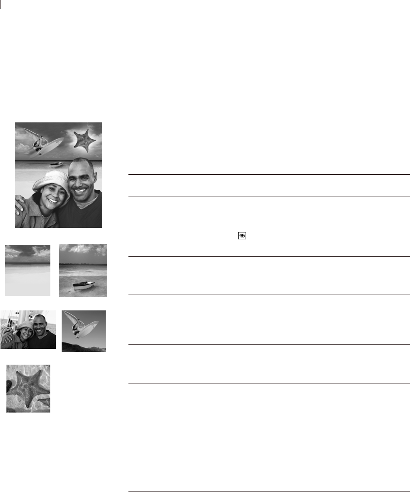
Chapter 14: Working with Layers
364
Using Layers with Photographic Images
When you open a digital photograph or scanned image in Paint Shop
Pro, the image is on the background layer. For most photographic
enhancements, such as cropping, correcting colors, or retouching,
you can work on this background layer without ever adding another
layer.
However, there are many ways to use layers with your photographic
images to make changes easier and create interesting effects:
Original photographs and the
resulting photo collage
Task How to Do It with Layers
Preserve the original
image before
making changes.
Make a duplicate copy of the background layer
(choose Layers > Duplicate). Turn off the visibility
of the background layer (click the layer’s Visibility
button ) and make all changes to the duplicate
layer.
Make color and
tonal corrections.
Use adjustment layers instead of changing the image
directly. For more information, see “Using
Adjustment Layers” on page 382.
Add text or
graphics.
Add them as vector objects to a new vector layer. (If
you add them to the raster layer with the image, you
must add them as raster data and they’ll be difficult
to edit.)
Create interesting
effects.
Duplicate the background layer, apply an effect to
the duplicate, and then change the opacity or blend
range of the modified layer to blend the two layers.
Create a photo
collage.
Place each photograph on a separate layer. (For each
image, choose Edit > Copy to copy the image, select
the collage image, and choose Edit >
Paste as New Layer. Position each layer with the
Move tool.
Use each layer’s opacity setting and blend mode to
control how much of each layer shows through. Use
a mask to hide parts of a layer or create soft edges
around a layer.
Chapter 14: Working with Layers 365
Using Layers with Illustrations
Layers are invaluable for illustrations. Here are some of the many
ways to use layers:
Create a panoramic
photograph.
Take a series of photographs with overlapping
subject matter, then stitch the photographs together
using layers.
Create an image with a canvas large enough to
display the panorama, then copy each photograph
onto a separate layer. Decrease the opacity of one
layer to see though it as you use the Move tool to
match up the edges of the other photograph. Do this
with each layer, then return the layers to 100 percent
opacity.
Task How to Do It with Layers
Individual layers and the final
illustration
Task How to Do It with Layers
Make changes
easier.
Create individual components on separate layers to
make them easy to edit together. For example, if
you have an illustration of a car speeding down a
highway in the mountains, create the car, the driver,
the highway, and the mountains on separate layers.
Move multiple
layers together
on the image
canvas.
Link or group layers that need to move together.
For example, link the car and the driver in this
example so that when you move the car to the left,
the driver moves too.
Edit graphical
elements.
Create objects you need to fine-tune or edit as
vector objects on vector layers.
Apply raster-
only commands
and effects to
vector objects.
Create a new layer with raster copies of the vector
objects. To do this, duplicate the vector layer and
then convert it to a raster layer. Turn off the
visibility of the vector layer.
Experiment with
changes.
Make a copy of a layer and try out changes. Turn
the visibility of a layer off and on to see which
works best in the overall image.
Save work-in-
progress.
Keep a copy of the intermediate steps of
transformations, then turn off the visibility of those
layers. If you need to go back a few steps at a later
date, you’ve got the data.

Chapter 14: Working with Layers
366
Adding New Layers to Images
There are many ways to add layers to images. Create a new layer,
promote the background to a regular layer, duplicate an existing
layer, or make a selection and turn it into a layer.
Creating New Layers
Create new layers to use for placing new elements in your images.
To create a new layer:
1 On the Layers palette, click the layer which you want to add a layer
above.
2 Do one of the following:
To create a new raster layer, click the New Raster Layer
button or choose Layers > New Raster Layer.
To create a new vector layer, click the New Vector Layer
button or choose Layers > New Vector Layer.
To create a new Art Media layer, click the New Art Media
Layer button or choose Layers > New Art Media layer.
To create a new mask layer, click the New Mask Layer button
or choose Layers > New Mask Layer > Show or Hide. For
information on mask show or hide layers, see “Creating New
Mask Layers” on page 392.
To create a new adjustment layer, choose Layers >
New Adjustment Layer and choose a type of adjustment layer.
For information on adjustment layers, see “Using Adjustment
Layers” on page 382.
3 Edit the layer properties as desired and click OK. For more
information, see “Editing Layer Properties” on page 368.
The new layer is added above the active layer. It is named with the
type of layer and a number, such as “Vector Layer 1.” To rename the
layer, see “Renaming Layers” on page 368.
Color depth
An image must be greyscale or 16
million color to create adjustment
layers or more than one raster
layer. If you have an image of
another color depth, Paint Shop
Pro prompts you to convert it to 16
million colors when you try to add a
new adjustment or raster layer.
Alternative ways to create
new layers
For all layer types, place the cursor
over a layer name on the Layers
palette, and then right-click and
select the new layer type from the
context menu.
To create a layer with default layer
properties, press Shift and click
one of the new layer buttons on the
Layers palette: New Raster Layer,
New Vector Layer, New Art
Media Layer, or New Mask Layer.

Chapter 14: Working with Layers 367
Promoting a Background Layer to a
Regular Raster Layer
When you want the background layer to function like a regular raster
layer, promote it to a layer. Unlike the background layer, raster
layers support transparency and can be moved anywhere within the
stacking order.
To promote a background layer:
Choose Layers > Promote Background Layer, or right-click on the
layer and select Promote Background Layer from the Layers context
menu.
Duplicating Layers
Duplicate a layer within an image to use as a starting point for a new
layer, or to try out edits and effects while keeping the original layer
intact. Or, copy a layer to another image.
To duplicate a layer within the same image:
Do one of the following:
Click its name on the Layers palette, then choose Layers >
Duplicate.
Right-click its name on the Layers palette, then choose Duplicate
from the context menu.
Click its name on the Layers palette, choose Edit > Copy to copy
the layer, and then choose Edit > Paste > As New Layer.
The duplicated layer is added just above the current layer.
To copy a layer to another image:
Do either of the following:
On the Layers palette, click and drag the name of the layer or
layer group onto an open image, and then release the mouse
button. Paint Shop Pro adds the layer above the selected layer of
the second image.
On the Layers palette, click the name of the layer or layer group
that you want to copy, choose Edit > Copy, select the image to
copy to, and then choose Edit > Paste > As New Layer. The layer
is pasted to the center of the canvas.
More about background
layers
For more information, see
“Background Layer” on page 361.
Copying all layers to
another image
Use the Browse window to copy all
layers of an image into another
image.
For more information, see “Copying
One Image into Another Using the
Browser” on page 162.

Chapter 14: Working with Layers
368
Creating Raster Layers from Selections
Use the Selection menu’s Promote Selection to Layer command to
promote a selection to a layer. Use the Selection, Freehand
Selection, or Magic Wand tool to make a raster selection of raster or
vector data. The new layer is always a raster layer.
You can also copy a raster selection and paste it as a new layer.
To create a raster layer from a selection:
1 Use the Selection, Freehand Selection, or Magic Wand tool to make
a selection on the image.
2 Do one of the following:
Choose Selections > Promote Selection to Layer. The new
layer is named Promoted Selection.
Choose Edit > Copy to copy the selection, and then choose
Edit > Paste > As New Layer. The new layer is named Raster
plus a number (Raster 1).
Editing Layer Properties
Layer properties are everything you see on the Layers palette: the
name, layer grouping and linking, layer opacity, blending,
transparency protection, and layer icon highlight colors. To change
properties, double-click a layer name to display the Layer Properties
dialog or make changes in the right panel of the Layers palette. For
information about editing an adjustment layer, see “Editing an
Adjustment Layer” on page 384.
Renaming Layers
As you add layers to an image, you may find it convenient to rename
the layers so they are easy to identify on the Layers palette.
How to start a new vector
layer with a vector selection
Use the Object Selection tool to
select one or more vector objects,
choose Edit > Copy to copy the
object(s), and then choose Edit >
Paste > As New Layer.
Cleaning up selection edges
When you promote a selection,
some of the pixels surrounding the
selection border may be included,
especially when the selection is
anti-aliased or feathered. Use the
Matting commands to clean up the
border by removing these pixels.
To clean up a selection before you
copy or promote it, see “Cleaning
Up the Edges of a Selection” on
page 209.
To clean up a layer created from a
selection, see “Cleaning up the
Edges of Layers Created from
Selections” on page 381.
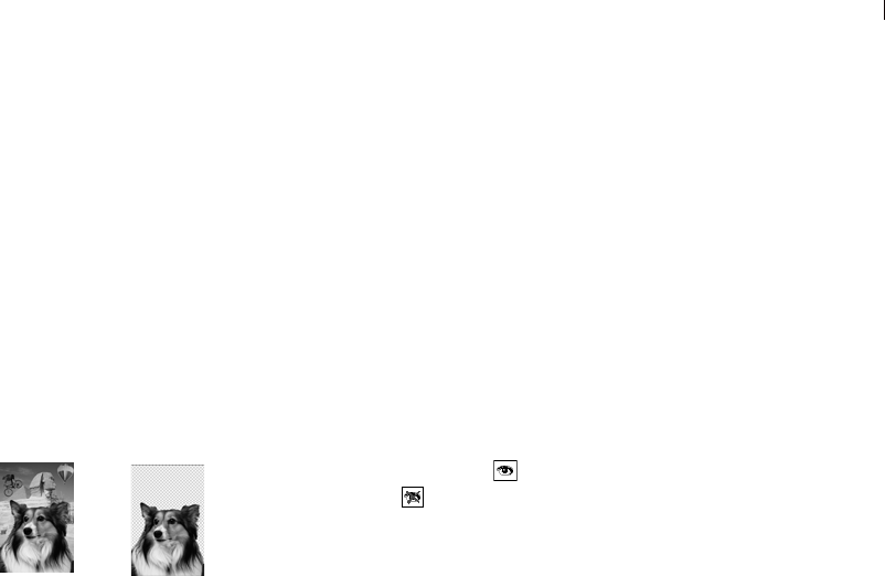
Chapter 14: Working with Layers 369
To rename a layer:
1 On the Layers palette, right-click the name of the layer and choose
Rename from the context menu.
2 Type the name and press Enter.
Showing and Hiding Layers, Groups,
and Vector Objects
Use the Visibility toggles on the Layers palette to make layers, layer
groups, or vector objects visible or invisible in the image. These
items remain in the image but are hidden. When a layer is visible, the
Visibility toggle displays . When a layer is hidden, the Visibility
toggle displays .
To show or hide individual layers and layer groups:
Do one of the following on the Layers palette:
Click the Visibility toggle for each layer or Layer Group you
want to show or hide.
Note: Hiding a layer group hides all of the layers within that
group.
To show one layer only, right-click a layer name and choose
View > Current Only from the context menu.
To show all layers:
Choose Layers > View > All, or right-click a layer name and choose
View > All from the context menu.
To invert which layers are shown or hidden:
Right-click a layer name and choose View > Invert from the
context menu. All previously visible items become invisible and
all invisible items become visible.
Right-click the layer name of a linked group and choose
View > Invert from the context menu.
To show or hide vector objects:
On the Layers palette, click the Visibility toggle for each vector
object you want to show or hide.
Alternative way to rename
Double-click the layer name to
display the Layer Properties dialog
and enter a new name in the Name
edit box.
Original image, and image with
all layers but one made invisible

Chapter 14: Working with Layers
370
Grouping Layers
Create layer groups to group multiple layers together. Layer groups
allow you to do the following:
Organize the Layers palette.
Set layer properties, such as opacity and blend mode, for the
whole group.
Limit the effect of adjustment layers to layers below them in a
group rather than in the entire image.
Move all grouped layers in the stacking order by clicking and
dragging the layer group name.
Move layers together on the image canvas—if the group is
linked. (Otherwise grouped layers move independently.) For
more information, see “Linking Layers and Layer Groups” on
page 371.
Layer groups can contain raster, vector, mask, and adjustment layers,
and must contain at least one layer. Layer groups can also contain
other layer groups (called nested groups). If you move all of the
layers out of a layer group, Paint Shop Pro deletes the layer group.
Note
Adjustment and mask layers cannot be the bottom layer.
Vector objects cannot be moved from their layer group.
To create a layer group:
1 On the Layers palette, click the first layer to be in the layer group.
2 Do one of the following:
On the Layers palette, click the Layer Group button .
Choose Layers > New Layer Group. The Layer Properties
dialog opens. Make changes as necessary and click OK.
Choose Layers > Arrange > Move Into Group.
The layer group is created, and the selected layer becomes part of
the layer group. By default, the layer group is named Group with
a number (for example, Group 1).
3 To add a layer to the layer group, click its name and drag it into
the layer group. A black line shows the position until you release
the mouse button.
Note: You can also add a layer group within a layer group (called
a nested group).
Modify that layer group
Here are some of the possible
ways to modify a layer group:
Edit its layer properties, such as
its opacity and blend mode. See
“Editing Layer Properties” on
page 368.
Drag it to a new position in the
image’s stacking order. All of its
layers move too.
Rename it. See “Renaming
Layers” on page 368.
Delete it—Paint Shop Pro
deletes all of its layers too. See
“Deleting Layers or their
Contents” on page 381.
How to add a layer to the
bottom of a layer group
Drag the layer to the second-to-
bottom position. Then drag the
bottom layer up.
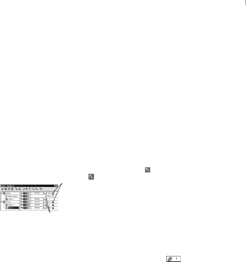
Chapter 14: Working with Layers 371
To remove a layer from the group:
Drag the layer to a new position outside the layer group, or choose
Layers > Arrange > Move Out of Group.
To ungroup layers:
Select the layer group that you want to ungroup, and then choose
Layers > Ungroup Layers.
Linking Layers and Layer Groups
Use layer linking to have layers move together on the image canvas
when you move one layer with the Move tool. To link individual
layers, use the Layer Link button on the Layers palette. By default,
this button says “None.” Change each layer that you want to link to
the same number, say “1” or “2.” Left-click to increase the number;
right-click to decrease it.
Use group linking to have all layers within a layer group move
together on the image canvas. The Group Link button on the Layers
palette displays a blue icon when the group is linked or a grey
icon when the group is not linked.
Layer links take precedence over group links. For example, Layer
Group 1 is linked and contains Layer1, Layer2, and Layer3. Layer1
is set to link number 1. Layer4 (outside of the layer group) is also set
to link number 1. If you move Layer4, Layer1 will move. If you
move Layer2, Layer1 will not move.
To link layers:
For each layer you want to link, change its link set number to the
same number. Do either of the following on the Layers palette:
Left-click the Layer Link button to increase the number.
Right-click the Layer Link button to decrease the number.
Double-click each layer name to display the Layer Properties
dialog, change the Link Set number, and then click OK.
An image with a linked group
and linked layers
Layer Link
button
Group Link
button
Chapter 14: Working with Layers
372
To unlink layers:
For each layer you want to remove from the link set, do either of the
following on the Layers palette:
Left-click or right-click the Layer Link button until it displays
None.
Double-click the layer name to display the Layer Properties
dialog, change the Link Set number to 0, and then click OK.
To link or unlink layer groups:
Do either of the following on the Layers palette:
Click the Group Link button . A grey button means the group is
unlinked.
Double-click the layer name to display the Layer Properties
dialog, mark or clear the Group is Linked check box, and then
click OK.
Changing Opacity of Layers
To create interesting effects, vary the opacity of a layer from the
default of 100 percent (fully opaque) down to 0 percent
(transparent). When a layer is partially transparent, layers below it
show through.
To change the opacity of all layers within a layer group, set the
opacity of the layer group.
The Opacity setting of the Layers palette displays the opacity of each
layer. The overall opacity of a layer and the opacity of individual
pixels are independent of each other. For example, if a pixel starts at
50% opacity and the layer is set to 50% opacity, the pixel will appear
25% opaque. If the layer is also in a layer group that is set to 50%
opacity, then the pixel opacity will be 12.5% opaque.
To set the opacity of a layer or layer group:
1 On the Layers palette, click the name of the layer.
2 Do one of the following:
Drag the Opacity slider to the desired percentage.
Double-click the layer name to display the Layer Properties
dialog, change the Opacity setting, and click OK.
Does linking affect the
stacking order?
No. Linking affects only
movements within the image
canvas using the Move tool.
The only way to move layers
together in the stacking order is to
group them. When you move a
group layer in the stacking order,
all layers move (regardless of
whether the group is linked or not).
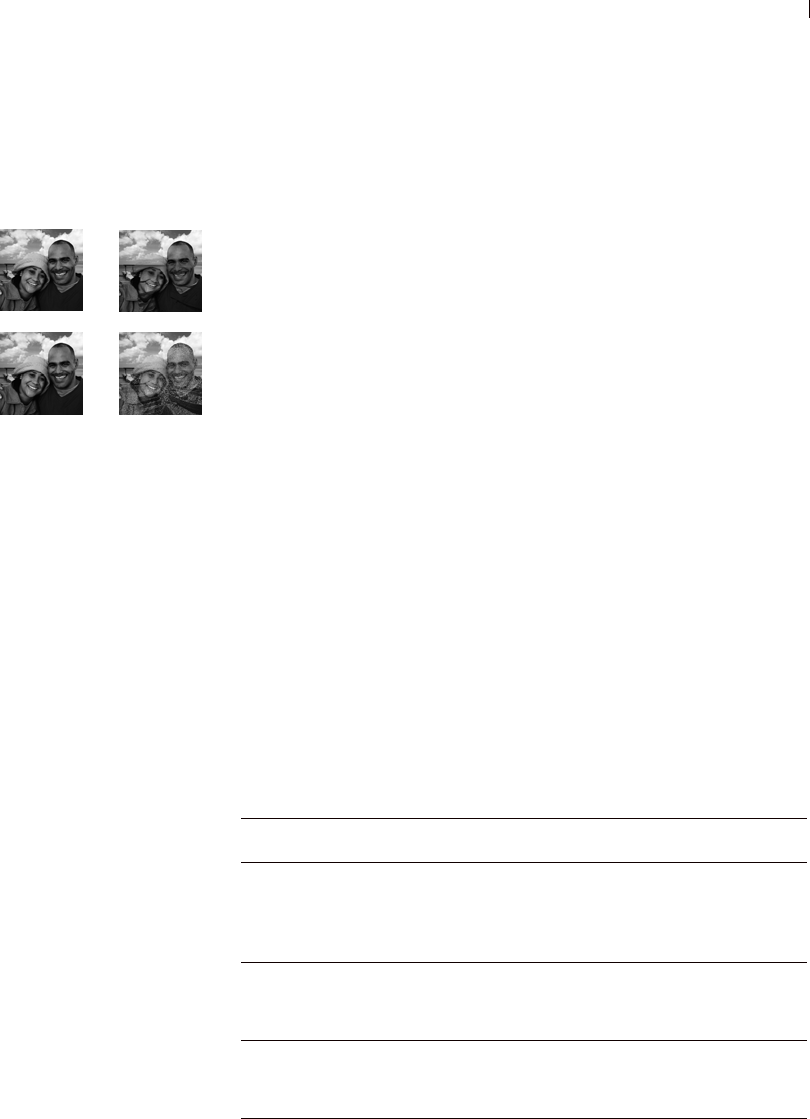
Chapter 14: Working with Layers 373
Blending Layers
Create interesting effects by changing the way pixels of one layer
blend with pixels of underlying layers. Paint Shop Pro contains a
variety of blend modes that specify how it blends pixels. The image
displays the blended pixels, but layers are not actually combined.
By default, each layer has a blend mode of Normal, which blends
pixels based on the opacity of the selected layer. The pixels of the
selected layer are blended with the combination of all underlying
layers, not just the layer directly beneath it.
To limit the pixels that the blend mode affects, set the blend range.
See “Setting Blend Ranges” on page 376.
To set the blend mode of a layer:
On the Layers palette, click the Blend Mode drop-down list of the
layer you want to set and select the blend mode from the list. For
descriptions of the blend modes, see “About Blend Modes” below.
About Blend Modes
The table describes each of the blend modes. In the table, “selected
layer” refers to the layer for which you are setting the blend mode.
Note
Several of the blend modes have been enhanced, the transfer of color
channels has been improved. These blend modes may not be
compatible with other applications. Use the Legacy blend modes for
compatibility with other applications.
Blend modes: Normal, Darken,
Luminance, and Dissolve
Color depth and layers
The Hue, Saturation, Color, and
Luminance blend modes are
available only for 16 million color
images.
The Multiply, Screen, Difference,
and Exclusion blend modes
produce the same result no matter
how layers are ordered within the
Layers palette. Blend Mode Result
Normal Displays pixels of underlying layers based on the opacity
of pixels on the selected layer. If data is fully opaque, no
pixels show through. As the opacity decreases, more
pixels from underlying layers show through.
Darken Displays pixels in the selected layer that are darker than
the underlying layers. Pixels lighter than the underlying
layers disappear.
Lighten Displays pixels in the selected layer that are lighter than
the underlying layers. Pixels darker than the underlying
layers disappear.

Chapter 14: Working with Layers
374
Hue Applies the hue of the selected layer to the underlying
layers (without changing the saturation or lightness). This
blend mode was introduced in Paint Shop Pro 8, and is an
improvement on the original Hue blend mode (Hue
(Legacy)).
Hue (Legacy) This blend mode was first introduced in version 5 of Paint
Shop Pro, and functions similarly to the Hue blend mode.
It is retained for the sake of compatibility with older
versions of Paint Shop Pro.
Saturation Applies the saturation of the selected layer to the
underlying layers (without affecting the hue or lightness).
This blend mode was introduced in Paint Shop Pro 8, and
is an improvement on the original Hue blend mode
(Saturation (Legacy)).
Saturation
(Legacy)
This blend mode was first introduced in version 5 of Paint
Shop Pro, and functions similarly to the Saturation blend
mode. It is retained for the sake of compatibility with
older versions of Paint Shop Pro.
Color Applies the hue and saturation of the selected layer to the
underlying layers (without affecting the lightness). This
blend mode was introduced in Paint Shop Pro 8, and is an
improvement on the original Color blend mode (Color
(Legacy)).
Color
(Legacy)
This blend mode was first introduced in version 5 of Paint
Shop Pro, and functions similarly to the Color blend
mode. It is retained for the sake of compatibility with
older versions of Paint Shop Pro.
Luminance Applies the luminance (or lightness) of the selected layer
to the underlying layers (without affecting the hue or
saturation). This blend mode was introduced in Paint
Shop Pro 8, and is an improvement on the original
Luminance blend mode (Luminance (Legacy)).
Luminance
(Legacy)
This blend mode was first introduced in version 5 of Paint
Shop Pro, and functions similarly to the Luminance blend
mode. It is retained for the sake of compatibility with
older versions of Paint Shop Pro.
Multiply Combines the colors of the selected layer with the
underlying layers to produce a darker color. Multiplying
any color with black produces black. Multiplying any
color with white leaves the color unchanged.
Blend Mode Result
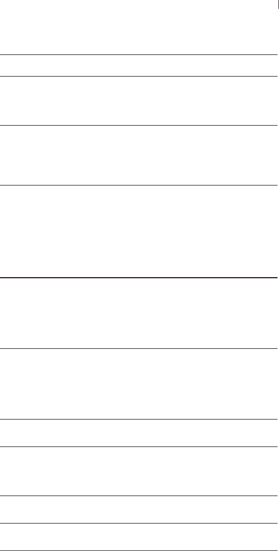
Chapter 14: Working with Layers 375
Screen Lightens the colors of underlying layers by multiplying
the inverse of the selected and underlying layers. The
result is a color that is the same or a lightened version of
the selected layer.
Dissolve Randomly replaces the colors of some pixels on the
selected layer with those of the underlying layers to create
a speckled effect. The selected layer’s opacity determines
the number of pixels replaced; the lower the opacity, the
more pixels that are replaced.
Overlay Combines the Multiply and Screen blend modes. If the
color channel value of underlying layers is less than half
the maximum value, the Multiply blend mode is used. If
the color channel value is greater than or equal to half the
value, the Screen blend mode is used. The Overlay blend
mode shows patterns or colors of the selected layer while
preserving the shadows and highlights of underlying
layers.
Hard Light Combines the Multiply and Screen blend modes. If the
color channel value of the selected layer is less than 128,
the Multiply blend mode is used. If the color channel
value is greater than or equal to 128, the Screen blend
mode is used. In general, use the Hard Light blend mode
to add highlights or shadows.
Soft Light Combines the Burn and Dodge blend modes. If the color
channel value of the selected layer is less than 128, the
Burn blend mode is used. If the color channel value is
greater than or equal to 128, the Dodge blend mode is
used. In general, use the Soft Light blend mode to add soft
highlights or shadows.
Difference Subtracts the selected layer’s color from the color of the
underlying layers.
Dodge Lightens the image by having the lightness values of the
colors in the selected layer lighten the colors of
underlying layers. Light colors produce the most
lightening; black has no effect.
Burn Darkens the image by having the lightness values of the
selected layer reduce the lightness of underlying layers.
Exclusion Creates an effect similar to but softer than the Difference
blend mode.
Blend Mode Result
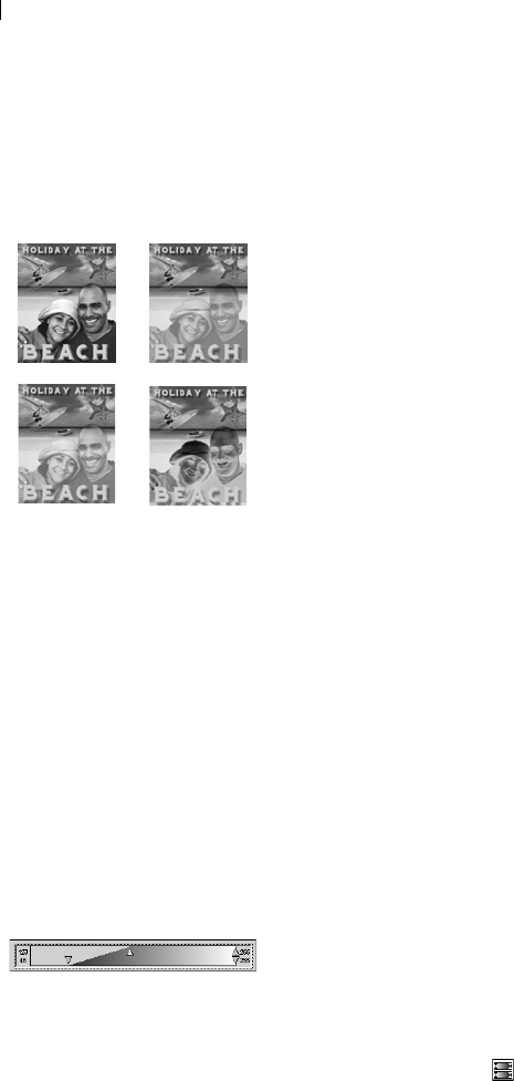
Chapter 14: Working with Layers
376
Setting Blend Ranges
In addition to setting the blend mode of a layer, you can set the blend
range. This range limits the pixels that the blend mode affects. By
default, the blend mode applies to all pixels. Blend ranges set the
opacity based on brightness or color channel to drop colors out of the
selected layer and make other colors show through.
To set the blend range:
1 On the Layers palette, select a layer and set its blend mode. (See
“Blending Layers” on page 373.)
2 Double-click the layer name to open the Layer Properties dialog.
3 Click the Blend Ranges tab.
4 In the Blend Channel drop-down list, select a channel to use
when blending layers. Select Grey Channel to have the lightness
values of layers determine opacity. Select Red Channel, Green
Channel, or Blue Channel to have the respective color values
determine opacity.
5 Set the opacity ramp for the channel as follows:
First, drag the upper arrows to indicate the values at which the
opacity is 100 percent.
Next, drag the lower arrows to indicate the values at which the
opacity is 0 percent.
Note that the values on the left side indicate the ramp up values,
while the values on the right side indicate the ramp down values.
For example, in the graphic in the left column, the selected
layer’s opacity is 100 percent between lightness values of 43 and
126, and falls off at the lightest and darkest areas.
6 Click OK.
Paint Shop Pro applies the blend only to the pixels that fall within
the range you selected. The right panel of the Layers palette displays
the Blend Range icon to indicate that a blend range is being used.
Protecting Transparent Areas
To apply tools and effects only to areas of a raster layer with data,
use the Lock Transparency feature on the Layers palette. Transparent
areas remain protected when you paint, apply effects, paste
selections, or perform other edits.
Blend ranges: normal, 50%,
60%, and 75%
Setting the blend ranges

Chapter 14: Working with Layers 377
Note
This feature applies to raster layers only. You cannot lock the
transparency of vector, adjustment, mask, or group layers. Also,
background layers do not support transparency.
When transparency is locked, the Lock Transparency button displays
. When a transparency is not locked, the Lock Transparency
button is grey .
To lock or unlock the transparency:
Do one of the following:
On the Layers palette, click the Lock transparency button of the
appropriate raster layer.
Double-click the layer name to display the Layer Properties
dialog, mark or clear the Lock transparency check box, and click
OK.
Setting Icon Highlight Colors
To organize the Layers palette visually, specify the highlight colors
for layers and layer groups. The highlight color displays as the
background of the icon to the left of the layer or group name. It has
no effect on the image itself.
In a layer group, layers that have not been assigned individual
highlight colors inherit the color of the parent layer. As an example,
use the same highlight color for all layers in layer group and use a
different color to highlight other layers or layer groups.
To set the highlight color of an icon:
1 On the Layers palette, double-click the name of the layer to open
the Layer Properties dialog.
2 Mark the Highlight in Layers palette check box.
3 Do one of the following:
To select a new color, click the color box next to the check
box. Choose a color and click OK.
To choose from recently used colors, right-click the color box
and click a color.
4 At the Layer Properties dialog, click OK. The icon now displays
the highlight color.

Chapter 14: Working with Layers
378
Modifying Layers
Modify layers to change the look of your image. Arrange the
stacking order, move layers within the image canvas, merge layers,
clean up edges of layers created from selections, or delete layers.
Arranging the Stacking Order of Layers
The arrangement of layers within your image is critical to what the
image looks like. If one layer is above another one, that layer’s data
can cover data below it.
To change the stacking order of layers—which changes the resulting
image—move layers on the Layers palette. If a layer or a layer group
has components, such as vector objects or grouped layers, all the
components move with it.
To move one layer, layer group, or vector object:
On the Layers palette, click the name of the layer, layer group, or
vector object and drag it to a new position. A black line shows the
position until you release the mouse button.
When you drag an item, the cursor changes into a hand . If it
displays a null symbol , you cannot move the selected item to a
particular position. For example: The background layer cannot be
moved. There can never be a layer below the background layer. A
vector object cannot be moved into a raster layer. Mask and
Adjustment layers cannot be at the bottom of an image or a layer
group.
To move multiple vector objects:
1 On the Layers palette, click the first vector object.
2 Press Shift and click each additional vector object, or right-click
and choose Select all.
3 Drag the selected objects to a new position. A black line shows
the position until you release the mouse button.
Moving the background
layer
The background layer is always the
bottom layer—it cannot be moved.
To change its position, promote it
to a raster layer first. See
“Promoting a Background Layer to
a Regular Raster Layer” on
page 367.
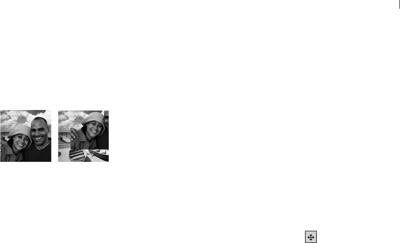
Chapter 14: Working with Layers 379
Moving Layers within the Image Canvas
Use the Move tool to move the contents of an entire layer anywhere
within the image canvas. If you move part of a layer off the canvas,
Paint Shop Pro does not crop it. You can move it back to the canvas,
or increase the canvas size to show the additional data.
Note
You cannot use the Move tool on the background layer. To move the
contents of the background layer, promote it to a regular raster layer
first. See “Promoting a Background Layer to a Regular Raster
Layer” on page 367.
To move a layer within the image canvas:
1 On the Layers palette, select the layer you want to move.
2 On the Tools toolbar, click the Move tool .
3 Click and drag in the image to move the layer to a new position.
4 To limit the Mover tool to the current layer, press and hold the
Shift key while you click the image and drag the layer.
Merging Layers
Merging layers is also called flattening. You can merge selected
layers, or all of the layers in an image. Merging layers decreases the
memory requirements for the image. Paint Shop Pro merges layers
based on the blend modes, converts vector data and vector text to
raster data, and replaces transparent areas of the background layer
with white.
Always make a backup copy of the original .PspImage image before
you merge layers. Once you merge layers, you cannot edit the layers
separately. Unless you are certain you have finished editing the
image, it’s best not to merge layers.
To merge two layers together:
1 Make sure one layer is located directly above the other on the
Layers palette.
2 Click the name of the layer above the one you want to merge it
with.
Original image, and with one
layer moved to the right
Where’s the layer?
If you move a layer off the image
canvas, you can no longer see it.
To get the data back, press the
Shift key while dragging it with the
Mover tool. Or, increase the canvas
size enough so that the layer
appears, move it to where you
want, then decrease the canvas
size again.
Saving flattened images
Many file formats, such as JPEG,
GIF, and TIF, do not support multi-
layered images. When you save to
these formats, Paint Shop Pro
merges all layers into a single
background layer.

Chapter 14: Working with Layers
380
3 Choose Layers > Merge > Merge Down to merge the two layers.
The following table describes how layer types are merged:
To merge all layers:
Choose Layers > Merge > Merge All (Flatten) to merge the layers into
one background layer.
To merge all visible layers:
1 On the Layers palette, click the Visibility toggle for each layer that
you do not want to merge.
2 Choose Layers > Merge > Merge Visible to merge all visible
layers into a raster layer named Merged. Invisible layers are not
affected. The new raster layer, which maintains the transparency
information of the original layers, is the active layer.
Note: If a visible layer is in a layer group, only the visible layers
in that group will be merged. If the layer group is marked
invisible (making all layers within the group invisible), none of
the layers within the group will be merged.
To merge all layers in a layer group:
1 On the Layers palette, click the layer group, or a layer within the
group, that you want to merge.
2 Choose Layers > Merge > Merge Group to merge all layers in the
group into one raster layer.
Top Layer Any layer Vector Art Media Mask Any Layer Any Layer
Merged with Raster Vector Background Mask Background Mask /
Adjustment
Creates Raster Vector Background Mask Background Not Permitted

Chapter 14: Working with Layers 381
Cleaning up the Edges of Layers Created
from Selections
When you promote or paste a selection to create a layer, some of the
pixels surrounding the selection border are included, especially
when the selection is anti-aliased or feathered. The Layers > Matting
commands clean up the border by removing these pixels.
There are three Matting commands: Remove Black Matte, Remove
White Matte, and Defringe.
Use the Remove Black Matte or Remove White Matte command
when the selection came from an image with a black or white
background. These commands remove the black or white pixels at
the layer edges.
Use the Defringe command when the selection came from an image
with a colored background. Defringing bleeds non-feathered pixels
in the layer edges outward and over the “jaggies” in the feathered
part of the layer.
To use a Matting command:
1 On the Layers palette, click the name of the layer that was created
from a selection.
2 Do one of the following:
To remove the black matte, choose Layers > Matting >
Remove Black Matte.
To remove the white matte, choose Layers > Matting >
Remove White Matte.
To remove a colored matte, choose Layers > Matting >
Defringe to open the Defringe dialog. Enter the number of
pixels to defringe and press Enter.
Deleting Layers or their Contents
To remove a layer from an image, delete the entire layer. Or, delete
the contents of a layer to keep the layer within the image; raster and
vector layers become transparent and the background layer is filled
with the current background color and material.
To delete a layer:
1 Make sure nothing is selected outside the layer you wish to delete.
Color depth
These commands work on 16
million color and greyscale images
only. To increase the color depth of
an image, see page 261.
Using matting on a
selection
To clean up the edges of a
selection before you promote or
copy it, use the Selections >
Matting commands. See “Cleaning
Up the Edges of a Selection” on
page 209.

Chapter 14: Working with Layers
382
2 On the Layers palette, click the name of the layer you want to
delete.
3 Click the Delete Layer button on the Layers palette toolbar, right-
click and choose Delete from the context menu, or drag the layer
to the Delete Layer button .
To delete the contents of a layer:
1 Make sure nothing is selected outside the layer you wish to delete.
2 On the Layers palette, click the name of the layer.
3 Press the Delete key or choose Edit > Clear.
Using Adjustment Layers
Adjustment layers are correction layers that adjust the color or tone
of underlying layers, without modifying their pixels directly. Choose
from these types of adjustment layers: Brightness/Contrast, Channel
Mixer, Color Balance, Curves, Hue/Saturation/Lightness, Invert,
Levels, Posterize, and Threshold.
All adjustment levels have equivalent commands on the Adjust
menu. The advantage of an adjustment layer is that you do not
modify the image layers themselves, so it’s easier to make quick
changes to the color and tonal adjustments. Add adjustment layers to
test various color corrections or to see how several corrections look
when you combine them. Hide, delete, or edit adjustment layers.
An adjustment layer applies to all layers below it that are at the same
level, as follows:
If the adjustment layer is at the main level (rather than in a layer
group), it applies to all layers below it in the stacking order.
If an adjustment layer is in a layer group, it applies only to layers
within the group that are lower in the stacking order.
To add an adjustment layer:
1 On the Layers palette, click the layer which you want to create an
adjustment layer above.
2 To apply the adjustment layer to a selection, make a selection.
3 Choose Layers > New Adjustment Layer and select the type of
adjustment layer.
How to create an
adjustment layer that
applies to one layer only
Create a layer group with the one
layer, and then add the adjustment
layer above the layer in the layer
group.
Chapter 14: Working with Layers 383
A dialog with the name of the adjustment layer opens. The
preview windows show the image before and after changes. The
Adjustment tab shows the color and tonal correction settings to
change.
Note: The General tab includes layer properties such as layer
name, blend mode, and opacity. Change these properties here or
on the Layers palette. For more information, see “Editing Layer
Properties” on page 368.
4 To reset values to default settings, in the Presets drop-down list
choose Default. Or, double-click the adjustment layer to open the
Properties dialog, and click the Reset to Default button .
5 Modify the settings on the Adjustment tab, and then click OK.
The adjustment layer is added just above the previously selected
layer.
About Adjustment Layer Types
Chapter 6, Making Color and Tonal Corrections describes in detail
each type of adjustment layer. The table shows specific sections to
refer to within that chapter.
Type of
Correction Adjustment
Layer For More Information
Adjust color
balance
Color Balance See “Changing the Color Balance of
Shadows, Midtones, and Highlights” on
page 129.
Hue/Saturation/
Lightness
See “Adjusting the Hue, Saturation, and
Lightness in Unison” on page 130.
Channel Mixer See “Adjusting the Color Channels” on
page 133.
Adjust
brightness
and contrast
Brightness/
Contrast
See “Manually Adjusting Brightness
and Contrast” on page 135.
Curves See “Adjusting Individual Brightness
Values” on page 136.
Levels See “Adjusting the Lightness Levels” on
page 139.

Chapter 14: Working with Layers
384
Editing an Adjustment Layer
Edit an adjustment layer to change the color or tonal correction. Or,
change the layer properties such as layer name and opacity.
To edit an adjustment layer:
1 On the Layers palette, double-click the name of the adjustment
layer that you want to edit. Or, select the layer and choose Layers >
Properties.
The Layer Properties dialog opens.
2 On the Adjustment tab, modify the color or tonal correction
settings. For detailed information, refer to the appropriate section
as listed in “About Adjustment Layer Types” on page 383.
3 Click the General tab to modify the general layer properties such
as layer name, blend mode, and opacity. Change these properties
here or on the Layers palette. For more information, see “Editing
Layer Properties” on page 368.
4 Click OK.
Modifying Portions of Adjustment
Layers
Sometimes most of an adjustment layer correction works well, but
one part of an image doesn’t need all of the correction. One way to
solve this challenge is to make a selection in the image and create an
adjustment layer for that selection. However, if the image has
multiple areas that need different levels of correction, use a more
flexible approach of creating one adjustment layer and modifying
portions of it.
Reduce or
remove
colors
Invert See “Creating Negative Images” on
page 144.
Threshhold See “Creating Black-and-White Images”
on page 142.
Posterize See “Reducing the Number of Lightness
Levels” on page 143.
Type of
Correction Adjustment
Layer For More Information
How to delete an
adjustment layer
Delete an adjustment layer just as
you do any other type of layer.
Click the layer name and then click
the Delete Layer button on the
Layers palette toolbar.
To undo a deletion, click the Undo
button or press Ctrl + Z, or use the
History palette.

Chapter 14: Working with Layers 385
Adjustment layers are greyscale layers. Use the painting tools to
selectively change which parts of the image get the full correction
and which parts get partial or no correction.
Adjustment layers contain pixels that can display 256 shades of grey.
These grey levels indicate the amount of correction.
White pixels mean Paint Shop Pro applies the full correction that
you specify.
Black pixels mean Paint Shop Pro applies no correction.
Grey pixels vary the correction. For lighter greys, Paint Shop Pro
applies close to the full correction. For darker greys, Paint Shop
Pro applies close to no correction. Middle grey means Paint Shop
Pro applies the correction at half strength.
Here are the basics of selectively modifying adjustment layers:
When you first create an adjustment layer, all pixels in the layer
are white (full strength correction).
If you create an adjustment layer when there is an active
selection, all pixels in the selection are white (full strength
correction) and all other pixels are black (no correction).
When you select an adjustment layer, the Material palette
displays black, white, and 254 shades of grey as available colors.
To modify portions of the adjustment layer, use the painting tools
to paint with shades of grey.
To see what the pixels of an adjustment layer look like, click the
Mask Overlay button . Or, position the cursor over the layer
name. The layer thumbnail displays the greyscale adjustment
layer.
Using the Layers palette
The Layers palette lists all layers in an image. The order of layers on
the palette is the order of layers in the image. The top layer is listed
first and the bottom layer is listed last. Change this stacking order by
dragging a layer to a new position on the Layers palette.
Note
Adjustment and mask layers cannot be the bottom layer.
Vector objects cannot be moved from their layer group.
Create layer groups to organize the Layers palette. Link layers or
groups so they move together when you use the Move tool in the
image.
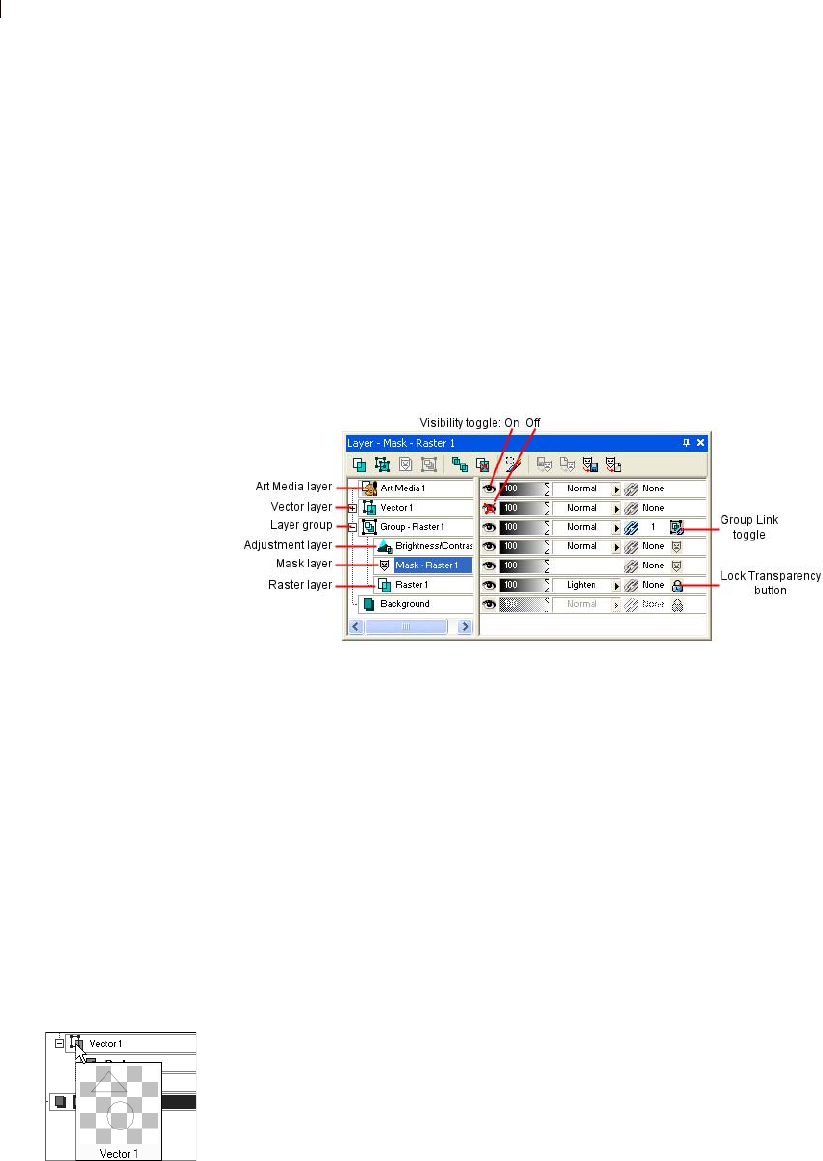
Chapter 14: Working with Layers
386
The left panel of the Layers palette displays the names of layers and
layer groups. The icon to the left of each name indicates the type of
layer (background, raster, vector, mask, adjustment, group, or
floating selection). When there are more layers than the palette can
display, use the scroll bars on the right side to move the list of layers
up or down.
The right panel of the Layers palette displays options for the layer,
including visibility, opacity, blend mode, link set, and lock
transparency.
The Layers palette toolbar includes buttons for command tasks, such
as adding a new raster or vector layer.
Displaying the Layers palette
Display or hide the Layers palette, or move it anywhere on the
screen. For information on moving, docking, and undocking the
Layers palette, see “Using Palettes” on page 15.
To display or hide the Layers palette:
Choose View > Layers palette or press F8.
Viewing the Contents of Layers
The image window shows all visible layers in the image. To view a
thumbnail of a layer’s contents, use the Layers palette.
To turn off or on the visibility of layers in the image window, see
“Showing and Hiding Layers, Groups, and Vector Objects” on
page 369.
Seeing layer contents
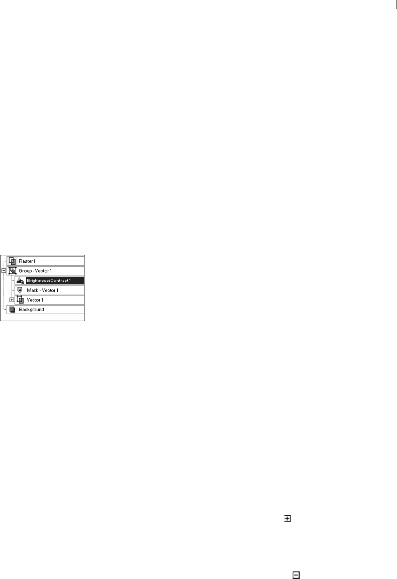
Chapter 14: Working with Layers 387
To view the contents of one layer:
On the Layers palette, move the cursor over a layer name to display
a thumbnail of the layer contents.
To set the size of the layer thumbnail:
1 Choose File > Preferences > General Program Preferences.
2 Click the Display and Caching tab.
3 Set the desired thumbnail size by adjusting the Thumbnail /
Preview size setting in the upper right corner of the tab.
Selecting Layers
When an image has more than one layer, you must select the layer
you want to work on. Changes to the image affect only the selected
layer (also called the active layer). You can select only one layer at a
time.
To select a layer:
On the Layers palette, click the name of the layer to highlight the
selected layer.
Expanding and Contracting Layers and
Layer Groups
The Layers palette displays its components like the “tree” of folders
and directories in Windows Explorer. Items that have sub-
components have a minus sign in front of them when expanded or a
plus sign when contracted.
Expand a vector layer or layer group to see the names of its sub-
components. Contract a vector layer or layer group to make the
Layers palette easier to navigate.
To expand a layer or layer group:
On the Layers palette, click the plus sign in front of the vector
layer or layer group name.
To contract a layer or layer group:
On the Layers palette, click the minus sign in front of the vector
layer or layer group name.
Selecting a layer

Chapter 14: Working with Layers
388

389
.
Working with Masks
A mask is a greyscale image that is applied to a layer. Use mask
layers hide and show parts of a layer, fade between layers, and create
other special effects. A mask can be created from a selection, from
an alpha channel, or an existing image. Masks can completely cover
a layer, or cover a layer with varying levels of opacity.
Contents About Masks . . . . . . . . . . . . . . . . . . . . . . . . . . . . . . . . . . . . . . 390
Creating Masks . . . . . . . . . . . . . . . . . . . . . . . . . . . . . . . . . . . . 391
Deleting Masks . . . . . . . . . . . . . . . . . . . . . . . . . . . . . . . . . . . . 396
Editing Masks . . . . . . . . . . . . . . . . . . . . . . . . . . . . . . . . . . . . . 397
Loading Masks . . . . . . . . . . . . . . . . . . . . . . . . . . . . . . . . . . . . 399
Saving Masks . . . . . . . . . . . . . . . . . . . . . . . . . . . . . . . . . . . . . 402
CHAPTER 15
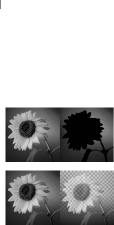
Chapter 15: Working with Masks
390
About Masks
A mask layer covers parts of another layer completely or with
varying levels of opacity. Use masks to fade between layers or to
create special effects with precision. For example, mask all details
around the main subject in a photograph, or use a mask to create a
Web page navigation bar that fades away.
You can create a new mask layer that you can paint on which hides
or shows underlying layers. You can also create a mask layer from
an image, a selection, or the luminance of an image. In addition, use
the sample masks (stored in the Masks folder of the Paint Shop Pro
program folder) and apply them as is, or customize them.
Mask layers function similar to other types of layers. Turn the
visibility of the mask layer on or off, change the overall opacity of
the mask layer, or link the mask layer to other layers. For more
information, see “Editing Layer Properties” on page 368.
Mask layers are automatically saved with the image in the .PspImage
format. You can also save a mask to an alpha channel or as a separate
image file on a disk. For more information, see “Loading Masks” on
page 399.
How Masks Affect Underlying Layers
A mask layer applies to all layers below it that are at the same level,
as follows:
If a mask layer is in a layer group, it applies only to layers within
the group that are lower in the stacking order.
If the mask layer is at the main level (rather than in a layer
group), it applies to all layers below it in the stacking order.
To change which underlying layers the mask applies to, on the
Layers palette drag the mask layer to a new position in the stacking
order. For more information, see “Arranging the Stacking Order of
Layers” on page 378.
Mask layers can never be the bottom layer in the image or in a layer
group.
Original and masked images
Color depth
Masks work with greyscale with
transparency and 16 million color
images only. To increase the color
depth of an image, see page 261.

Chapter 15: Working with Masks 391
Mask Layers as Greyscale Raster Layers
Masks are greyscale raster layers—they contain pixels that can
display 256 shades of grey. Rather than applying grey paint to the
image, however, the levels of grey correspond to levels of opacity, or
masking. White pixels show underlying layers, black pixels hide
underlying layers, and grey pixels show varying amounts of
underlying layers. The darker the grey, the more the underlying
pixels are masked.
Even though masks are raster layers, you can create masks that hide
or show portions of vector layers.
When you select a mask layer, the Materials palette displays black,
white, and 254 shades of grey as available colors. Paint on the mask
layer to change the visibility of underlying pixels. All tools and
commands that work on greyscale raster layers work on masks. For
the Pen, Preset Shapes, and Text tools (which can create raster or
vector objects), create raster objects on mask layers.
Creating Masks
There are several ways to add a mask to an image. You can create a
new mask layer completely showing or hiding the underlying layers.
You can also create a mask from an image or a selection.
Note
Because background layers do not support transparency, you cannot
apply a mask to them. When the background layer is selected when
you create a new mask, you are prompted to promote the background
to a full layer.
See the contents of the
mask layer
To see what the mask layer looks
like, position the cursor over the
layer name on the Layers palette.
A thumbnail displays the greyscale
mask layer.

Chapter 15: Working with Masks
392
Creating New Mask Layers
To show or hide the underlying layers completely with the new
mask, choose from the Show All or Hide All Layer menu commands.
To create a new mask layer:
1 On the Layers palette, click the layer you want to mask.
2 Choose Layers > New Mask Layer and then choose the type of
mask:
Show All Shows all underlying pixels. All pixels of the mask are
white. The underlying layer will appear unchanged. Paint the
mask with greys or black to hide portions of the underlying
layers.
Hide All Hides all underlying pixels. All pixels of the mask are
black. The underlying layer will be completely hidden. Paint the
mask with white or greys to show portions of underlying layers.
The mask layer and the selected layer are added to a new layer
group. The mask layer applies to the selected layer only. To apply it
to all underlying layers, drag it from the layer group to the main
level.
To view the mask on the image, on the Layers palette click the Mask
Overlay toggle .
For more information on editing the mask, see “Editing Masks” on
page 397.
Other ways to create a new
mask layer
On the Layers palette, right-click
the layer to which you want to add
a mask and choose New Mask
Layer > Show All to show all
underlying pixels or Hide All to
hide all underlying pixels. Or, click
the Show All button on the Layers
palette.
Hint for editing masks
Display the Overview palette
(choose View > Palettes >
Overview) while editing a mask so
that you can see the image as it
will print or display (without the
transparency grid or the mask
overlay).
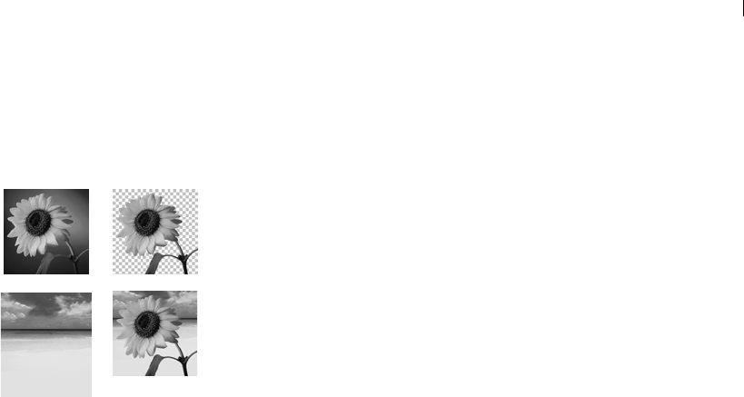
Chapter 15: Working with Masks 393
Creating Masks from Images
Use any image as a mask for another image. Paint Shop Pro converts
the image into greyscale raster data and uses it for the mask. The
original, or source, image is not altered.
Note
Another way to create a mask from an image is to load the image file
from disk; see “Loading Masks from Disk” on page 399.
To create a mask from an image:
1 Open the image that you want to use for the mask.
2 Select the image in which you want to create the mask layer.
3 On the Layers palette, click the layer you want to mask.
4 Choose Layers > New Mask Layer > From Image to open the Add
Mask From Image dialog.
5 In the Source window drop-down list, select the image to use for
the mask.
6 In the Create mask from group box, select an option:
Source luminance The luminance value of the pixel color
determines the degree of masking. Lighter colors produce less
masking; darker colors produce more masking. Transparent areas
completely mask the layer.
Any non-zero value Transparent areas completely mask the layer.
There is no gradation to the masking. Pixels with data (opacity of
1-255) become white pixels in the mask; transparent pixels
become black in the mask.
Source opacity The opacity of the image determines the degree
of masking. Fully opaque pixels produce no masking; partially
transparent pixels create more masking; transparent pixels
produce full masking.
7 To reverse the transparency of the mask data, mark the Invert
mask data check box. Black pixels become white, white pixels
become black, and greys are assigned their mirror value.
8 Click OK.
The mask layer and the selected layer are added to a new layer
group. The mask layer applies to the selected layer only. To apply it
to all underlying layers, drag it from the layer group to the main
level.
Using an image as a mask
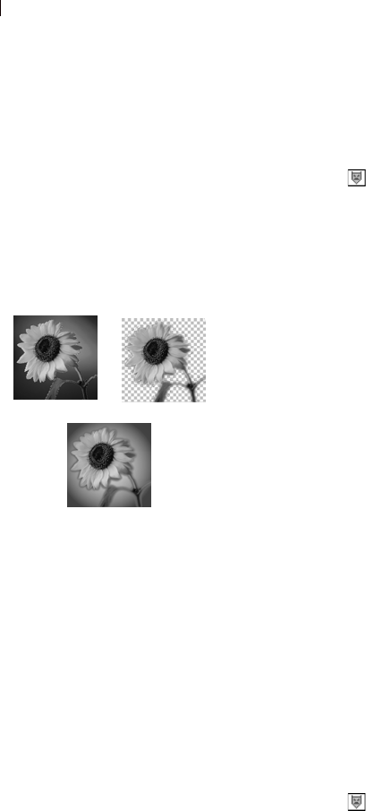
Chapter 15: Working with Masks
394
For information on editing the mask, see “Editing Masks” on
page 397.
To view the mask on the image, on the Layers palette click the Mask
Overlay toggle .
Creating Masks from Selections
Use a raster selection to create a mask that shows or hides the
selection.
To create masks from selections on vector layers, use the Selection,
Freehand Selection, and Magic Wand tools. You cannot use the
Object Selection tool.
To create a mask from a selection:
1 Use the Selection, Freehand Selection, or Magic Wand tool to make
a selection on a raster or vector layer in the image.
2 Do either of the following:
To mask the selection, choose Layers > New Mask
Layer > Hide Selection.
To mask everything except the selection, choose Layers > New
Mask Layer > Show Selection.
The mask layer and the selected layer are added to a new layer
group. The mask layer applies to the selected layer only. To apply it
to all underlying layers, drag it from the layer group to the main
level.
For information on editing the mask, see “Editing Masks” on
page 397.
To view the mask on the image, on the Layers palette click the Mask
Overlay toggle .
Using a selection as a mask
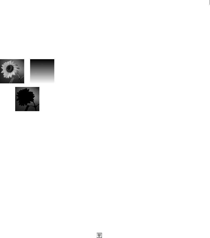
Chapter 15: Working with Masks 395
Creating Masks from Channels
When you split an image into its RGB, HSL, or CMYK channels,
Paint Shop Pro creates a greyscale image for each channel. Use one
of these channel images to create a mask for the original image or
another image.
To create a mask from a channel:
1 Split the image into channels using one of the Image > Split
Channel commands, and leave the resulting greyscale images open
in the workspace. For more information, see “Working with Color
Channels” on page 259.
2 Select the image where you want to create the mask layer.
3 Choose Layers > New Mask Layer > From Image to open the Add
Mask From Image dialog.
4 In the Source window drop-down list, select which channel
image to use for the mask.
5 In the Create mask from group box, select the Source opacity
option.
6 To reverse the transparency of the mask data, mark the Invert
mask data check box.
7 Click OK.
The mask layer and the selected layer are added to a new layer
group. The mask layer applies to the selected layer only. To apply it
to all underlying layers, drag it from the layer group to the main
level.
For information on editing the mask, see “Editing Masks” on
page 397.
To view the mask on the image, on the Layers palette click the Mask
Overlay toggle .
Using the greyscale channel as
a mask
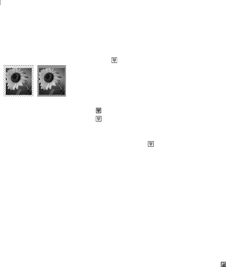
Chapter 15: Working with Masks
396
Displaying the Mask Overlay
When you create a mask, the image window shows the effect of the
mask, but does not display the mask automatically. Use the Mask
Overlay toggle on the Layers palette to display the mask overlay.
By default, the overlay is a 50 percent opacity red color for
completely masked pixels and lower opacity red for partially masked
pixels. When you paint or modify the mask, this overlay shows what
is painted or changed. To change the color and opacity of the mask
overlay, see “Changing the Mask Overlay Color” on page 398.
When the mask overlay is displayed, the Mask Overlay toggle
displays . When the overlay is hidden, the Mask Overlay toggle
displays .
To display or hide the mask overlay:
Click the Mask Overlay toggle , or choose Layers > View Overlay.
Deleting Masks
Delete a mask entirely from an image, or merge the mask with the
underlying layer and then delete the mask layer. If you merge the
mask, you can no longer edit it independently.
A mask saved to an alpha channel is not deleted when you delete the
mask layer.
To delete a mask:
1 Delete the mask in either of these ways:
On the Layers palette, right-click the name of the mask layer
and choose Delete.
On the Layers palette, click the name of the mask layer, and
then choose Layers > Delete, or click the Delete button .
Paint Shop Pro displays a message asking if you want to merge
the mask with the underlying layer.
2 Do either of the following:
To merge the mask with the layer, click Yes. Paint Shop Pro
merges the layers and deletes the mask layer.
To remove the mask from the image without affecting the
underlying layer, click No. Paint Shop Pro deletes the mask
layer.
Masked image with and without
overlay
Hiding masks
To turn off the visibility of a mask,
but keep it in the image, click the
Visibility toggle on the Layers
palette.

Chapter 15: Working with Masks 397
Deleting Masks from Alpha Channels
If you saved selections to alpha channels that you no longer need,
you can delete them. Delete alpha channels from the current image
only.
To delete an alpha channel:
1 Choose Image > Delete Alpha Channel to open the Delete Alpha
Channel dialog.
2 Select the alpha channel that you want to delete, or mark the
Delete all alpha channels check box.
3 Click Delete.
Editing Masks
Edit a mask the same way you edit any greyscale raster layer. Select
a mask layer on the Layers palette, and then use the painting tools or
the effects commands to modify the mask. When you edit a mask,
you change either the areas or the degree of masking. For example,
painting over an object to mask it changes the area, while applying a
gradient fill edits the degree of masking.
Remember that a mask layer is a greyscale layer with 256 levels of
grey that correspond to levels of masking. When you select a mask
layer, the Materials palette displays the greyscale palette. Apply
black or white to mask or erase the mask at 100 percent. Apply greys
to vary the level of masking.
Edit the layer properties of a mask, such as the name, visibility, or
opacity, in the same way you do any type of layer. For more
information, see “Editing Layer Properties” on page 368.
To create a gradient or textured mask, invert the mask, or change the
overlay color, refer to the following sections.
How do I view the
alpha channels?
To see what masks and selections
are saved to alpha channels in an
image, choose Image > Delete
Alpha Channel. Click the Alpha
Channel drop-down list to list all
alpha channels in the current
image. When you finish, click
Cancel.
Ways to modify masks
Use the painting tools. See
Chapter 11, Raster Painting.
Paint with gradients, textures, or
patterns. See “Creating Gradient,
Pattern or Texture Masks” on
page 399.
Apply effects commands. See
Chapter 9, Applying Effects.
Create a shape in one image, then
use it as a mask in another image.
See “Loading Masks” on page 399.
Use the Move tool to move the
mask layer within the image
canvas.

Chapter 15: Working with Masks
398
Changing the Mask Overlay Color
By default, the mask overlay displays red semi-transparent pixels to
show the mask on the image. Change the color or opacity for the
mask layer to make it easier to see on your image.
To change the mask overlay color and opacity:
1 Do one of the following to open the Layer Properties dialog:
On the Layers palette, double-click the mask layer button or
right-click the mask layer button and choose Properties.
Choose Layers > Properties.
2 Click the Overlay tab and change the following:
Overlay Color The default overlay color is pure red
(RGB 255, 0, 0). Click the color box and choose a new color.
Opacity The opacity of the overlay. The default is 50 percent.
3 Click OK.
Inverting Masks
To reverse the transparency of a mask, invert it. Black pixels become
white and white pixels become black. Greys become their mirror
value—the maximum value (255) minus the current value.
To invert a mask:
1 On the Layers palette, select the name of the mask layer.
2 Choose Layers > Invert Mask/Adjustment.
Displaying the Mask
Overlay
For more information on the mask
overlay, see “Creating Masks” on
page 391.
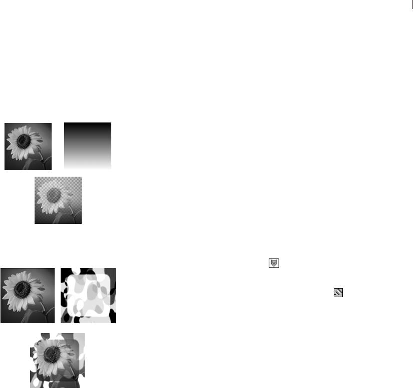
Chapter 15: Working with Masks 399
Creating Gradient, Pattern or Texture
Masks
Use a gradient, pattern, or texture mask to create interesting effects.
A gradient mask varies the opacity of an image from fully hidden to
fully shown. Use a gradient mask to fade an image in or out. A
pattern or texture mask varies the image opacity in a repeated pattern
throughout the image.
To create any of these masks, on the Materials palette select the
material (gradient, pattern, or texture) and then fill the mask layer
with it. When you choose a colored material, Paint Shop Pro
converts it to greyscale before applying it.
To create a gradient, pattern, or texture mask:
1 Create a new mask. See “Creating Masks” on page 391.
2 Click the Mask Overlay toggle on the Layers palette to display
the mask overlay.
3 On the Tools toolbar, click the Flood Fill tool .
Note: To fill all pixels in the mask, on the Tool Options palette
set the Match Mode to None.
On the Materials palette, select a gradient, texture, or pattern. See
“Choosing Gradients” on page 244, “Choosing Patterns” on
page 246, or “Choosing Textures” on page 247.
4 Left-click the mask to apply the foreground material; right-click
the mask to apply the background material.
Loading Masks
Once you have saved a mask to a hard disk or a removable disk, you
can load the mask into images without opening the original image.
Loading Masks from Disk
Load a mask file that you have saved or load one of the sample
masks that come with Paint Shop Pro. Mask files have a .PspMask
extension. Use the Layers > Load/Save Mask > From Disk command
to load mask files or load image files as masks.
Using a gradient mask
Using a pattern mask
Paint Shop Pro masks
The Masks folder of the Paint Shop
Pro program folder contains
sample masks, such as gradients
and several types of circles and
squares that frame images.

Chapter 15: Working with Masks
400
To load a mask from disk:
1 On the Layers palette, click the layer you want to mask.
2 Choose Layers > Load/Save Masks > Load Mask From Disk to
open the Load Mask From Disk dialog.
The Mask group box shows all masks in all directories listed in
your file locations for masks. To change the default directory,
click the Edit Paths button. For more information, see “Setting
File Format Associations” on page 79.
3 In the Mask group box, click the drop-down list to choose from
mask and image files.
The Preview group box displays the selected mask on the image
canvas.
4 In the Orientation group box, select from the following options:
Fit to canvas Adjusts the mask to fit the current image canvas
(stretching or contracting as needed).
Fit to layer Adjusts the mask to fit the current layer’s data
(stretching or contracting as needed). If the layer has not been
shifted beyond the edges of the canvas, this option is identical to
the Fit to Canvas option.
As is Places the mask starting in the top left corner of the current
layer; this option does not change the mask proportions. If the
mask image is smaller than the current layer, Paint Shop Pro by
default masks all pixels outside of the mask image boundaries.
5 In the Options group box, choose whether Paint Shop Pro shows
or hides pixels surrounding the loaded mask data (if there are
any). These options affect the mask only if the Orientation option
is As Is and the loaded mask is smaller than the current image
canvas.
Invert transparency To invert the transparency of the mask
image.
Hide all mask Makes surrounding pixels black to hide underlying
pixels.
Show all mask Makes surrounding pixels white to show
underlying pixels.
Use image value Makes surrounding pixels white or black
depending upon whether the original mask was a show all mask
or a hide all mask.
6 Click Load.

Chapter 15: Working with Masks 401
Paint Shop Pro adds the mask layer and the selected layer to a new
layer group. The mask layer applies to the selected layer only. To
apply it to all underlying layers, drag it from the layer group to the
top of the main level.
To view the mask on the image, on the Layers palette click the Mask
Overlay toggle .
Loading Masks from Alpha Channels
When you save a mask to an alpha channel within a .PspImage
image, you can load that mask from the alpha channel into the same
image or into any other image.
To load a mask from an alpha channel:
1 On the Layers palette, click the layer you want to mask.
2 Choose Layers > Load/Save Mask > Load Mask From Alpha
Channel to open the Load Mask from Alpha dialog.
3 In the Document drop-down list, select the image which contains
the alpha channel you want to load. (Choose from open images
with existing alpha channels only.)
4 In the drop-down list below the document name, choose the alpha
channel which contains the mask you want to load.
5 In the Orientation group box, select from the following options:
Fit to canvas, Fit to layer, or As is. For descriptions, see
page 400.
6 In the Options group box, select whether Paint Shop Pro hides or
shows pixels surrounding a loaded mask that is smaller than the
current image canvas. Choose a Hide all or Show all mask. To
invert the transparency of the mask image, mark the Invert
transparency check box. For detailed descriptions, see page 400.
7 Click Load.
Paint Shop Pro adds the mask layer and the selected layer to a new
layer group. The mask layer applies to the selected layer only. To
apply it to all underlying layers, drag it from the layer group to the
main level.
To view the mask on the image, on the Layers palette click the Mask
Overlay toggle .

Chapter 15: Working with Masks
402
Saving Masks
Paint Shop Pro automatically saves mask layers in the .PspImage
format. When you want to share a mask with others, or use a mask in
another image, save the mask to your hard drive or to an alpha
channel.
Saving Masks to Disk
When you save a mask to a hard disk or a removable disk,
Paint Shop Pro saves the mask as a separate file with a .PspMask
extension. You can then load this mask into other images without
opening the original image.
To save a mask to disk:
1 On the Layers palette, click the name of the mask layer.
2 Choose Layers > Load/Save Mask > Save Mask to Disk to open
the Save Mask To Disk dialog.
The Mask files group box displays the current masks in the
default Masks directory. The New mask group box displays the
current mask.
3 To change the folder where the mask file is saved, click the Edit
Paths button. By default, mask files are stored in the Masks
folder of the Paint Shop Pro program folder. For more
information, see “Setting File Format Associations” on page 79.
4 In the File name edit box, type a name for the mask file.
5 Click Save.
Saving Masks to Alpha Channels
Save a mask to an alpha channel within the current image or within
another image. An alpha channel is a data storage area in an image
which stores masks and selections. Alpha channels are like secret
compartments within a suitcase—use them to store things you may
need later. Masks and selections stored in alpha channels have no
effect on the look of an image. To use the stored masks or selections,
load them into the same image or another image.

Chapter 15: Working with Masks 403
When you save the image to a file format other than .PspImage
format, the alpha channels are not saved. Always keep a master copy
of your image in .PspImage format.
To save a mask to an alpha channel:
1 On the Layers palette, click the name of the mask layer.
2 Choose Layers > Load/Save Mask > Save Mask To Alpha Channel
to open the Save Mask to Alpha dialog.
The Add to document drop-down list displays all open
documents and below it are the alpha channels in the image (if
any).
3 To save a mask to an image’s alpha channel, select the image
name in the Add to document drop-down list. The image must be
open in Paint Shop Pro.
4 To edit the default name for the new alpha channel, type a new
name in the Name field.
5 Click Save.
Selections in alpha
channels
For information on saving or
loading selections in alpha
channels, see “Saving Selections
to Alpha Channels” on page 215.

Chapter 15: Working with Masks
404

405
Working with Text
The Text tool lets you place vector text objects (although you can
choose to create text on raster layers) on your image and set a variety
of options, including text direction. Afterward you can apply any of
Paint Shop Pro’s effects making text in your images stand out.
Contents Creating Text . . . . . . . . . . . . . . . . . . . . . . . . . . . . . . . . . . . . . 406
Formatting Text. . . . . . . . . . . . . . . . . . . . . . . . . . . . . . . . . . . . 410
Editing Text. . . . . . . . . . . . . . . . . . . . . . . . . . . . . . . . . . . . . . . 411
Moving Text . . . . . . . . . . . . . . . . . . . . . . . . . . . . . . . . . . . . . . 412
Applying Effects to Text. . . . . . . . . . . . . . . . . . . . . . . . . . . . . . 413
Converting Text to Curves . . . . . . . . . . . . . . . . . . . . . . . . . . . . 413
Creating Text on Object Paths . . . . . . . . . . . . . . . . . . . . . . . . . 414
Creating Text with Image Patterns . . . . . . . . . . . . . . . . . . . . . . 418
Scaling and Transforming Text. . . . . . . . . . . . . . . . . . . . . . . . . 418
CHAPTER 16

Chapter 16: Working with Text
406
Creating Text
Use the Text tool to create text on an image. Choose text colors on
the Materials palette and text options on the Tool Options palette,
then click in the image and enter text in the Text Entry dialog.
Be aware that if you have vector objects in your image (objects
created with the Pen, Ellipse, Rectangle, Symmetric Shape, or Preset
Shape tools), the behavior of the Text tool will be as follows:
To place text on the image (text not fit to a vector path), do not
click near a path.
To place text on a vector object or path without attaching to the
object or path, hold down the Alt key and click.
To place text on a vector object or path, place the Text tool cursor
on top of the object or path (the cursor shape will change to )
and click. See Creating Text on Object Paths for more
information.
To create text:
1 On the Tools toolbar, choose the Text tool .
2 On the Materials palette, make the desired Foreground/Stroke
property and Background/Fill property settings. The foreground
setting determines the text outline, while the background setting
determines the text fill (the area within characters).
For standard text with no outline, set the Stroke width on the
Tool Options palette to 0, or click the Foreground/Stroke
property's Transparent button.
For hollow text, click the Background/Fill property's
Transparent button.
3 On the Tool Options palette's Create as drop-list, choose the type
of text:
Vector creates vector text that resides on a vector layer. This is
the most editable form of text.
Selection creates a selection marquee in the shape of the text
characters. You can treat the selection as you would any made
from the Selection tools in that it can be moved, copied, filled,
etc. This form of text is not vector-based.
Floating creates raster text that is a floating selection. Ideally you
should place this type of text on it's own raster layer, otherwise it
is merged with the current layer and would be difficult to edit.
Text in images
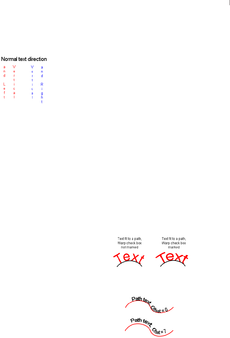
Chapter 16: Working with Text 407
4 Choose a text direction in the Direction drop-list:
Horizontal and Down : this creates "normal" text where
subsequent lines are placed below the top text line.
Vertical and Left : this places each character vertically, but
subsequent lines are placed to the left of the top line.
Vertical and Right : this places each character vertically, but
subsequent lines are placed to the right of the top line.
5 Choose the basic text formatting options, including Font, Size,
Stroke width (if you're using a Foreground/Stroke in the
Materials palette), Font style, and Alignment. See “Formatting
Text” on page 410.
6 Choose an Anti-alias option from the Anti-alias drop list:
Off applies no anti-aliasing.
Sharp applies a slight edge enhancement to the text.
Smooth applies a slight filtering effect similar to removing a
moire pattern.
7 Optionally, you can choose a Line Style (affects only the stroke)
as well as Join and Miter settings. Normal text uses the default
line style labeled +Solid in the Line Style drop list.
8 The Warp check box affects text fit to a path. When marked, the
text will "warp" around the curves of the path (if the path is not
curved, you won't see the effect). Also, be aware that warping is
set on a per-character basis, so part of a text block can be warped
and part will appear unwarped. When this option is not marked,
the text fits on the path in a more straight manner.
9 When creating text fit to a path, the Offset setting allows you to
define the distance between the text and the path it is fit to. This
setting will have no effect for text not fit to a path.
Text direction examples
What’s the real text size?
For the Size setting, the only way
to guarantee true WYSIWYG text
is if your image resolution is equal
to your printing resolution.
Note: Use negative
Offset values to
place text below the
path.

Chapter 16: Working with Text
408
10 The last Text tool options include:
Leading: Sets the vertical space between text lines.
Kerning: Sets the horizontal space between characters. Kerning
values are expressed as 1.000 being equal to one EM.
Auto kern check box: Mark this option to factor in the font's
built-in kerning values.
Tracking: Lets you set an equal amount of space across selected
characters.
11 Once all your Tool Options are ready, click in the image where
you want to place the text. The Text Entry dialog opens. Note the
following points regarding where you click to place the text:
To place text on the image (text not fit to a vector path), do not
click near a path.
To place text on a vector object or path without attaching to
the object or path, hold down the Alt key and click.
To place text on a vector object or path, place the Text tool
cursor on top of the object or path (the cursor shape will
change to ) and click.
12 Type the text. As you type in the dialog, the text displays on the
image. To add a line break, press Enter.
13 To change any of the text formatting options, in the Text Entry
dialog, highlight the words or characters that you want to change,
and then make changes on the Tool Options palette. For more
information about editing, see “Applying Effects to Text” on
page 413.
14 Mark the Remember Text check box to display the entered text
the next time you open the Text Entry dialog.
15 Click Apply. The text displays on the image. If you've added
vector text, note also that this will be reflected in the Layers
palette.
A Note About the Text Size Setting
The Text tool's Size setting in the Tool Options palette is expressed
in points where the calculation is relative to the pixel per inch
resolution of your monitor. Most monitors today are designed to be
96 pixels to the inch. Points are a unit of measurement where 72.27
points are equal to one inch. However, the computer world has
changed the measurement to 72 points per inch. Thus a 24-point font
is roughly equivalent to 1/3 of an inch.

Chapter 16: Working with Text 409
Be aware that this is relative to the number of pixels per inch. The
calculation to go from size to display fontsize is :
fontsize = (Size x Monitor-pixels-per-inch) / 72
Using the above example of Size set to 24-point:
fontsize = (24 x 96) / 72 = 2304 / 72 = 32
since 32 / 96 = 1/3 then relative to the monitor specifications, the
fontsize is 1/3 of an inch.
But since our images also carry a resolution, (for example 200 pixels
per inch) and printers may have yet a different (usually higher)
resolution, a typical printer resolution is 300 dpi or 600 dpi or
greater.
In order for a 1/3 inch size font on a 300 dpi image, then the value
should be 100. Which means to correctly calculate the appropriate
size for points, the above algorithm should replace monitor pixels
per inch with image pixels per inch or image resolution.
For example, if your image dimensions were one inch wide by one
inch high, and the image resolution were 100 dpi, printing this image
on a 300 x 300 dpi printer will produce an image roughly one-third
of an inch square.
About Vector, Floating, and Selection
Text
The Text tool creates vector text, a text selection, or floating (raster)
text. Choose an option from the Create As drop-down list:
Vector Creates vector text, which is the only type of text you can edit
by changing the words, font type, style, and alignment. Use this
setting in most cases. When you want to apply raster-only tools
(such as the Paint Brush) or commands (such as applying a
3D effect), merge the vector layer to a raster layer.
If you create vector text while a raster layer is active, Paint Shop Pro
adds a new vector layer with the text.
Selection Creates a selection marquee in the shape of text, rather
than creating text as a painted object. Move, copy, fill, or otherwise
edit it just like any other selection. For example, use the Paint Brush
to paint the selection with a texture. You can also use a text selection
to create special effects. Delete the text selection to create words that
are cut out of the image. Or, create a text selection on a photographic
image, and then copy and paste the selection to a new image; the
result is text filled with the image.

Chapter 16: Working with Text
410
Floating (Raster) Creates raster text that is a floating selection. You
cannot exit raster text, so use this type when you know that the
words and formatting will not change. Use raster text when you want
to apply raster-only tools (such as the Paint Brush) or commands
(such as applying a 3D effect).
It’s best to create raster text on a new raster layer. That way, you can
easily select the text and make changes such as stretching it with the
Deform tool.
When Paint Shop Pro defloats the raster text selection (such as when
you click another tool), the raster text is merged with the underlying
raster layer. If a vector layer is active, Paint Shop Pro creates a new
raster layer.
Formatting Text
When you enter or edit text with the Text tool, select from the
following formatting options on the Tool Options palette:
Font A set of characters (letters, numbers, and symbols) that share a
common look. Click the Font drop-down list to see the font family
name (such as Arial or Times New Roman) displayed in the font
itself.
Size The point size of the text. How small or large a font looks in the
image depends upon the image’s resolution. 72-point text is
approximately 1 inch high in a 72-dpi image, but will be smaller in
images with higher resolution. For more information on text size,
refer to the section A Note About the Text Size Setting found earlier
in this chapter.
Stroke Width The text outline pixel width. Choose 0 pixels to have
no outline.
Anti-alias Anti-aliasing smooths the jagged edges of text by
softening the color transition between edge pixels and background
pixels. Anti-aliasing greatly increases the number of colors in the
image. This makes it challenging to reduce the number of colors and
thus reduce file size. Anti-aliasing may cause stray colors to appear
along the edges of text.
Alignment How text is aligned in relation to the initial cursor
position—where you clicked in the image to insert the text.
Aligns the left edge of each text line to the initial cursor
position.
Text with several formatting
options
Chapter 16: Working with Text 411
Aligns the center of each text line to the initial cursor
position.
Aligns the right edge of each text line to the initial cursor
position.
Type Style The style of text; choose bold, italic, or both.
Underline or Strikethrough Click to underline text. Click to
place a horizontal line through text.
Line Options Define the look of the text outline (stroke). Options
include Line Style (such as solid or dashed), Join, and Miter Limit.
For details, see “Drawing Objects” on page 320. For information on
Custom line styles, see “Creating Custom Line Styles” on page 334.
Offset Sets the distance between the text and the path it is fit to. This
setting will have no effect for text not fit to a path
Leading: Sets the vertical space between text lines.
Kerning: Sets the horizontal space between characters. Kerning
values are expressed as 1.000 being equal to one EM.
Auto kern check box: Mark this option to factor in the font's built-in
kerning values.
Tracking: Lets you set an equal amount of space across selected
characters.
Editing Text
Use the Text tool to edit vector text. You can edit the characters and
their appearance.
Note: You cannot edit the characters or formatting of raster
text. To modify Raster text, use the Deform tool.
To edit vector text:
1 To open the Text Entry dialog, do one of the following:
On the Tools toolbar, click the Text tool, position the cursor
over the text in the image until the cursor turns to , then
click; or
Right-click the text and select Edit Text; or
On the Layers palette, double-click the text object; or
On the Layers palette, right-click on the text object and select
Edit Text from the context menu.

Chapter 16: Working with Text
412
The Text Entry dialog opens with the text highlighted.
In this dialog, you can only change highlighted text. If no text is
highlighted when you choose options, the options affect new text
you type at the cursor position.
2 Edit the text in any of these ways:
To format all text, keep it all highlighted and choose options
on the Tool Options palette or choose new colors or materials
on the Materials palette.
To format one or more characters, click and drag to highlight
the text you want to change, and choose options on the Tool
Options or Materials palette.
To add new text, click where you want to insert it and begin
typing.
To delete text, highlight the text and press Delete.
Moving Text
To move or position vector text on a layer, use the Object Selection
tool. To move raster text, use a selection tool like the Magic Wand
tool to select and move it.
To move vector text:
1 On the Tools toolbar, click the Object Selection tool .
2 Select the text you want to move. A bounding box surrounds the
text.
3 Move the cursor inside the bounding box, the cursor changes
to .
4 Click and drag the text anywhere within the image.
To move raster text:
1 On the Tools toolbar, select one of the Selection tools. For details,
see “Using the Selection Tools” on page 192.
2 Select the text you want to move.
3 Move the cursor inside the selection marquee, the cursor changes
to .
4 Click and drag the text anywhere within the image.
How to move text to
another layer
To move text to another layer,
select the text, then cut and paste
it to another layer.
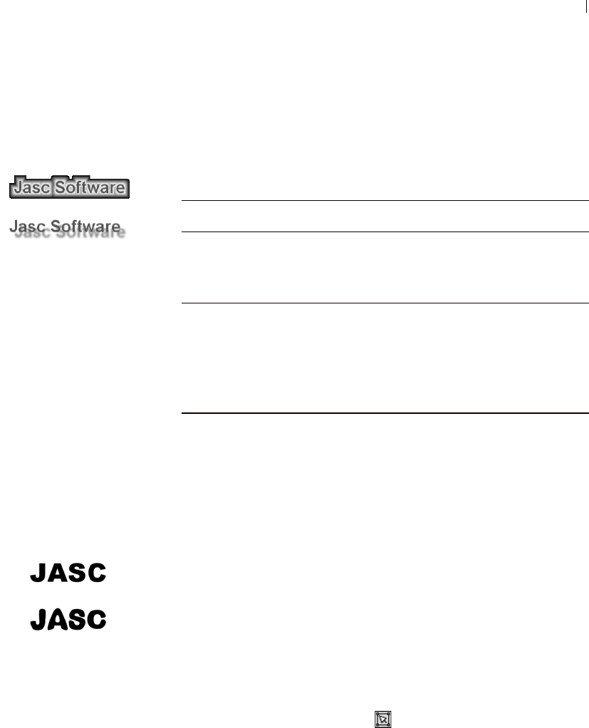
Chapter 16: Working with Text 413
Applying Effects to Text
Apply any of Paint Shop Pro’s effects to raster text to create an
endless variety of looks. Apply a drop shadow or a beveled edge,
turn text into brush strokes or colored chalk. For vector text, convert
it into a raster selection, and then apply effects.
Converting Text to Curves
To edit vector text as a vector object, convert it to curves. You can
then move or add nodes, change the angles of line segments, and
perform other edits using the Pen tool's Edit mode. Use this feature
to create interesting text.
Convert each letter into its own object, or convert the entire text into
one object with each letter as a separate contour within the object
path.
After you convert text to curves, it is no longer text—so you cannot
change the characters, their font or leading, or do any other text
edits.
To convert text to curves:
1 Use the Object Selection tool to select the text.
2 Do one of the following:
To convert the entire text object into one vector object, choose
Objects > Convert Text to Curves > As Single Shape. This
produces one path containing a contour for each letter.
Text with buttonize effect and
drop shadow effect
Type of Text How to Apply Effects
Raster Create the raster text on a transparent layer, separate
from other raster data in the image. Select the text on
the layer using the Magic Wand tool, and then apply
any of the commands on the Effects menu.
Vector Use the Object Selection tool to select the text.
Choose Selections > From Vector Object to create a
raster selection of the text, then choose Paste > As
New Layer. Follow the steps above for raster text.
Turn off the visibility of the vector text, but keep the
vector text in case you want to edit it.
Regular text, and text converted
to curves and modified with the
Pen tool
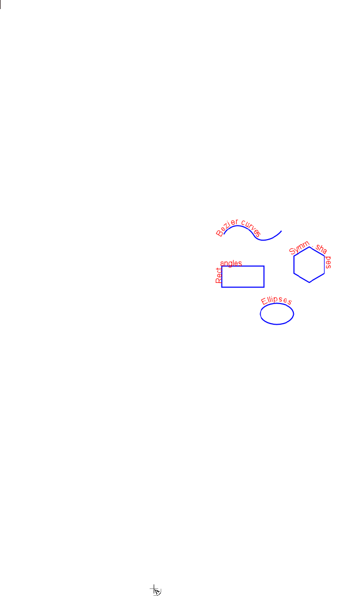
Chapter 16: Working with Text
414
To convert each letter into a separate vector object with its
own path, choose Objects > Convert Text to Curves > As
Character Shapes. To edit the nodes of the text, you must
select the letters individually.
3 To edit the nodes, choose the Pen tool and then choose Edit mode
in the Tool Options palette.
Creating Text on Object Paths
You can easily create text that fits any vector object. Every vector
object in Paint Shop Pro has a path (or outline) that defines its shape.
Fitting text to these paths can create fun and interesting effects.
Note: You cannot create deformed text on a path, Paint Shop
Pro will remove the deformation when placing the text on the
path.
There are two ways to create text on a path:
Create the path (a line or shape) first, and then create new text on
the path.
Create the path and the text as separate objects, and then fit the
text to the path.
To create new text on a path:
1 Use the vector drawing tools to create a vector shape.
2 Click the Text tool.
3 In the Tool Options palette's Create as drop-list, choose Vector
4 Select other options (font, size, alignment, offset, and so on) as
desired. Use the Materials palette to set the text's Background/
Fill property as well as its Foreground/Stroke property.
5 Move the cursor over the line or shape until the cursor changes to
, and then click. The Text Entry dialog displays.
Put some distance between
text and path
To change the distance between
the text and the object path,
change the Offset value in the Tool
Options palette.
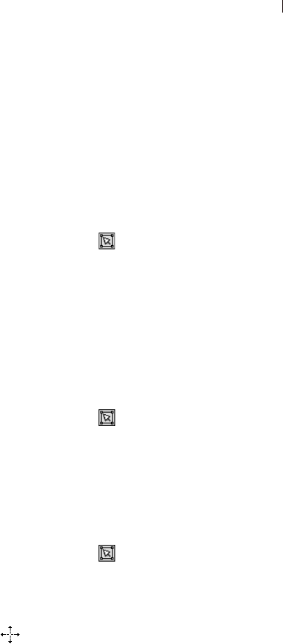
Chapter 16: Working with Text 415
Note: To place text on a vector object or path without attaching
to the object or path, hold down the Alt key and click.
6 Enter the text and click OK. The text displays along the path of
the shape
Fitting Existing Text to a Path
To attach a previously unattached text object to a previously
unattached path object:
1 Choose the Object Selection tool .
2 Select the text.
3 Hold down Shift and click the vector object to select it also.
4 Choose Objects > Fit Text to Path. The text aligns along the
object.
Detaching Text from its Path
To detach text from its associated vector object:
1 Choose the Object Selection tool .
2 Select the text or the vector object.
3 Choose Objects > Detach Object from Path.
Moving Text Along Its Path
To move text along the path it is attached to:
1 Choose the Object Selection tool .
2 Select the attached text.
3 Place the cursor over any part of the text (or over the selected
text's bounding box Centerpoint icon) so that the cursor shape
changes to this:
4 Drag the mouse to move the text. Note that as you drag you'll see
a small circular icon move in tandem with the text. This icon will
indicate the starting point of the text once you release the mouse
button.
Make the object disappear
After you align text to a vector
object, you can make the object
invisible. On the Layers palette,
click the Visibility toggle of the
object.
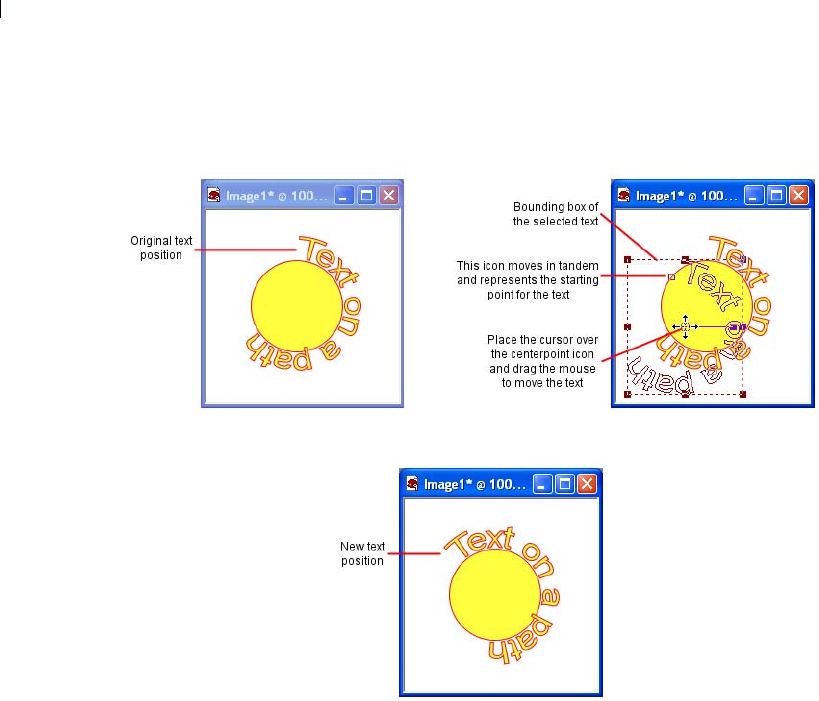
Chapter 16: Working with Text
416
5 Release the mouse button to place the text at the desired position.
Chapter 16: Working with Text 417
Aligning and Spacing Text on Object
Paths
When you create text along a path, the text placement depends upon
features of the text and the path.
Aligning Text on a path
Text is aligned based on
the insertion point Feature How it affects text on a path
Text alignment
(left, center, or
right).
For new text on a path:
Paint Shop Pro aligns the text using the position
where you clicked to insert the text. Left-aligned text
begins at that position. Center-aligned text is centered
on that position. Right-aligned text ends at that
position.
For existing text fit to a path:
Paint Shop Pro aligns the text using the start and end
nodes of the path. Left-aligned text begins at the start
node. Center-aligned text is placed midway between
the start and end nodes. Right-aligned text ends at the
end node.
Direction of path The text goes in the direction from the start node to
the end node. The direction determines whether the
text aligns right-side-up above the path or upside-
down below the path.
Reverse the path to change the direction. See
“Reversing the Direction of Contours or Paths” on
page 339.
Spacing between
text and path
The Offset value of the text determines the spacing
between the text and the path. Use positive values to
position the text above the path and negative values to
position the text below the path.
Open or closed
path
On open paths, text that is longer than the path hangs
from the end. The angle of the last line segment
determines the direction it hangs.
On closed paths, text that is longer than the path wraps
around itself.

Chapter 16: Working with Text
418
Creating Text with Image Patterns
There are several ways to create text that is filled with an image:
Scaling and Transforming Text
To scale (resize) and transform text:
For vector text, use the Object Selection tool to scale, rotate,
shear, distort, or apply perspective to text. For more information,
see “Resizing and Reshaping Vector Objects” on page 347.
For raster text, use the Deform tool to scale, rotate, shear, distort,
or apply perspective to a raster selection or a layer. For more
information, see “Scaling and Transforming Images” on
page 171.
Text filled with a pattern
Effect How to do it
Fill text with a
repeated image
Open the image you want to use to fill the text, click
the Background Material box on the Materials
palette, click the Pattern tab, and select the image
from the drop-down list. Use this background
material to create new vector or raster text, or to edit
existing vector text.
For existing raster text, paint or fill the text with the
background material.
Fill text with one
image
Open a copy of the image. Create new text as a
selection on the image (on the Text tool’s Tool
Options palette, in the Create As drop-down list
choose Selection). Then copy the selection to a new
image.

419
Automating Tasks
Automating a lengthy task or set of tasks is one of the many exciting
benefits of Paint Shop Pro. This chapter describes important time-
saving features:
Automated Productivity Scripts let you automate an action or set
of actions that you apply to images.
Binding scripts to icons that can be placed in toolbars or menus
for more convenient access.
Presets allow you to save dialog or tool settings for later use.
The Batch Process feature lets you, among other things, convert
multiple files from one file format to another.
The Batch Rename feature lets you rename multiple files at once.
Contents Using and Creating Presets . . . . . . . . . . . . . . . . . . . . . . . . . . . 420
Processing Multiple Files . . . . . . . . . . . . . . . . . . . . . . . . . . . . . 422
Renaming Multiple Files. . . . . . . . . . . . . . . . . . . . . . . . . . . . . . 424
Scripting Basics . . . . . . . . . . . . . . . . . . . . . . . . . . . . . . . . . . . 425
Running a Saved Script . . . . . . . . . . . . . . . . . . . . . . . . . . . . . . 427
Stopping or Undoing a Script . . . . . . . . . . . . . . . . . . . . . . . . . . 427
About Restricted Script Mode. . . . . . . . . . . . . . . . . . . . . . . . . . 428
Recording and Saving a Script . . . . . . . . . . . . . . . . . . . . . . . . . 429
Editing Scripts. . . . . . . . . . . . . . . . . . . . . . . . . . . . . . . . . . . . . 430
Binding Scripts to Icons . . . . . . . . . . . . . . . . . . . . . . . . . . . . . . 433
CHAPTER 17
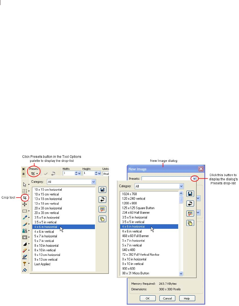
Chapter 17: Automating Tasks
420
Using and Creating Presets
Presets are essentially scripts that define the behavior, properties, or
settings of a dialog or tool. Many dialogs and tools come with
predefined, ready to use Presets. You can also design and save your
own Presets.
When you find yourself frequently using particular settings for a
dialog or tool, saving these settings as a Preset saves you the time
needed to define each dialog or tool setting each time you use it.
Simply save the settings and they'll appear in the Presets drop-list for
that tool or dialog
Examples of Presets
Shown below are two examples of Presets, one from the Crop tool,
and one from the New Image dialog.

Chapter 17: Automating Tasks 421
Most Paint Shop Pro dialogs and the Tool Options palette have the
following default presets:
Last Applied These are the settings last used in this dialog. Each
time the dialog opens, Paint Shop Pro displays the Last Used
preset settings.
Default These are the default program settings for this dialog or
tool. The default settings can provide a good starting point for
your work.
To choose a preset:
In the Presets drop-list, select the desired Preset from the list.
To reset values to default settings:
In the Presets drop-list, click the Reset to default button . To
reset a dialog to the settings that displayed when you opened the
dialog, hold down Shift and then click the Reset to default button.
To save settings as a preset:
1 Modify the dialog or tool settings.
2 Click the Save preset button . to open the Save Preset dialog.
3 Type a name for the Preset.
Note: You cannot use the names “Default” or “Last Applied”.
4 To enter additional Preset information, click the Options button,
and then enter information in the Author, Copyright, and
Description fields.
The Preset includes group box shows the data saved with this
Preset. To omit any of these items from the Preset, click the Save
button associated with the item (a red X will appear over it).
5 Click OK.
To delete a preset:
1 In the Presets drop-list, click the Resource Manager button .
2 In the Resource Manager dialog, select the preset you want to
delete.
3 Click Delete, and when prompted to confirm deletion, click Yes.
How do I edit a preset?
To edit a Preset, select it, modify
the dialog or tool settings, click the
Save Preset button, and type the
same preset name. When you are
prompted to replace the current
Preset, choose Yes.

Chapter 17: Automating Tasks
422
Processing Multiple Files
To process multiple files use the Batch Process feature. Depending
on your settings in the Batch Process dialog, Paint Shop Pro can
make copies of original files, convert and then save the copies in the
output folder you select.
To use the Batch Process feature:
1 Open the Batch Process dialog by choosing
File > Batch > Process.
2 Navigate to the folder containing the source (original) files.
3 In the Save Mode group box, choose one of the following
options:
New Type This is the most basic option, requiring only that a new
output type be set in the Type field of the Save Options group
box. You can also choose to run a script with this Save Mode.
This option will: a) read in the file, b) run the script (if defined)
against the file, c) save the file to its new location and/or name,
and d) convert it to the new file format.
Copy This option requires that a script is defined in the Script
group box. This option will: a) read in the file, b) run the script
against the file, and c) save the file to a new location and/or
name. With this option selected, the Type field and Options
button of the Save Options group box will be disabled.
Overwrite This option requires that a script is defined in the
Script group box. This option will: a) read in the file, b) run the
script against the file, and c) save the file to its original location
(the original file is overwritten). With this option selected, all
Save Options group box settings are inactive.
Obey Script This option requires that a script is defined in the
Script group box. This option will: a) read in the file, and b) run
the script against the file. With this option selected, all Save
Options group box settings are inactive.
Note: Since no save is performed, you should only use this
option when you know the script performs a save. If not, this
option will not have any effect.
4 In the Save Options group box, set the following (the Save Mode
settings affects what is available in this group box):

Chapter 17: Automating Tasks 423
Click the Type drop-list to select a new file format. If a format
has save options, the Options button is accessible. Click it to
open the Save Options dialog. Select the format options and
click OK to return to the Batch Process dialog.
Designate another output (destination) folder for the new files
by typing a path in the Folder field, or by clicking the Browse
button next to this field and navigating to another folder.
Unless you specify another output folder, Paint Shop Pro
saves the converted files in the same folder as the source files.
You also have the option of renaming the converted files. To
do so, click Modify to open the Modify Filename Format
dialog. The Rename Options list displays the choices for
renaming your files. Select an option and click Add to move it
into the Included list. Choose from the following options:
Custom Text When you choose this option, the program
displays a Custom text field below the Included list. Type
the text you want inserted into the filename.
Date The current date is added to the name.
Document Name Includes the original name in the new
name, but also allows for case changes (upper, lower).
Sequence The position of a file in the renaming process is
added to each file.
Time The current time is added to the name.
A preview of the new file naming scheme appears at the bottom
of the dialog. Click OK to go back to the Batch Process dialog.
5 To stop the conversion process if Paint Shop Pro encounters an
error, mark the Stop on error check box. If you do not mark it,
the program processes all the images without stopping. The error
messages appear in a Batch Conversion Status dialog.
Note: If you are overwriting files during processing, particularly
many files, you may want to leave this box unchecked to avoid
having to confirm the overwriting of each file.
6 Use the Script group box to run a script on all the files before
converting them. In the text entry box, enter the path for the
script, or click Browse and then navigate to where the script
resides. Mark the Run script in silent mode check box to ensure
the script runs in this mode.
7 If you have already selected files to process, click Start. If you
have not already selected the files to process, do one of the
following:

Chapter 17: Automating Tasks
424
To process specific files, press Shift while selecting
contiguous files or Ctrl while selecting non-contiguous files,
and then click Start.
To process all files displayed, click Select All.
The Batch Progress dialog opens, and the batch conversion starts.
The Current Step pane displays each filename and whether it is
converted, while the Job Progress bar indicates the conversion
progress. To stop the conversion, click Abort.
During the conversion, Paint Shop Pro might open other dialogs
requesting more information if you have selected Meta, PostScript,
Photo-CD, or RAW files.
8 After the files have been converted, either click OK to close the
dialog, or click Save Log to save the progress messages to a text
file. Clicking Save Log opens the Save As dialog. Type a name
for the file and click Save. Paint Shop Pro saves the information
with a .log file extension.
Renaming Multiple Files
To use the Batch Rename feature:
1 Open the Batch Rename dialog by choosing
File > Batch > Rename.
2 Navigate to the folder containing the source (original) files.
If necessary, use the Files of type field to display particular file
formats. Choose All Files to display the folder’s entire contents.
3 To define a new name for the files, click Modify to open the
Modify Filename Format dialog. The Rename Options list
displays the choices for renaming your files. Select an option and
click Add to move it into the Included list. Choose from the
following options:
Custom Text When you choose this option, the program
displays a Custom text field below the Included list. Type the
name you want applied to the converted files.
Date The current date is added to the name.
Document Name Includes the original name in the new name,
but also allows for case changes (upper, lower).
Sequence The position of a file in the renaming process is
added to each file.
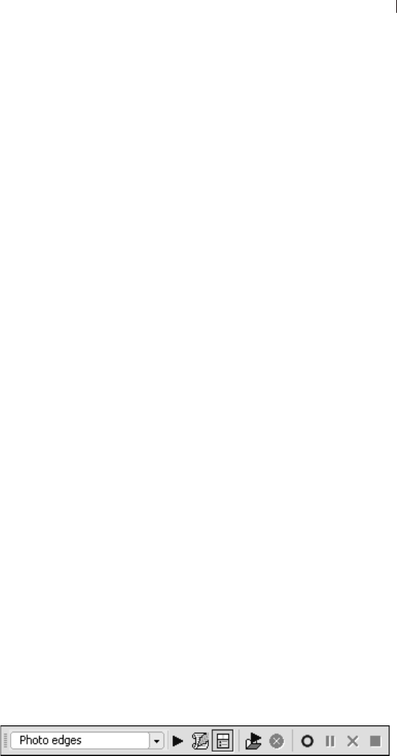
Chapter 17: Automating Tasks 425
Time The current time is added to the name.
A preview of the new file naming scheme appears at the bottom
of the dialog. Click OK to go back to the Batch Rename dialog.
4 To stop the rename process if Paint Shop Pro encounters an error,
mark the Stop on error check box. If you do not mark it, the
program processes all the images without stopping.
5 If you have already selected files to rename, click Start. If you
have not already selected the files to rename, do one of the
following:
To rename specific files, press Shift while selecting
contiguous files or Ctrl while selecting non-contiguous files,
and then click Start.
To rename all files displayed, click Select All.
Scripting Basics
One of the more powerful features in Paint Shop Pro is Scripting.
Paint Shop Pro has a full-featured scripting engine based on the
Python programming language (see http://www.python.org/ for more
information on this language). Although you can write your own
scripts using Python syntax, Paint Shop Pro’s built-in script recorder
can do this work for you, allowing you to script almost any action
within the application.
If, however, you choose to write a script in the Python language,
note that Python uses indentation to determine scoping, thus you
must be very careful about mixing spaces and tabs. We recommend
that you use a Python-aware editor such as PythonWin or Idle if you
choose to write your own scripts.
Displaying the Script Toolbar
You will find it much easier and faster working with scripts via the
Script toolbar. If it is not already displayed, choose
View > Toolbars > Script. The Script toolbar looks like this:
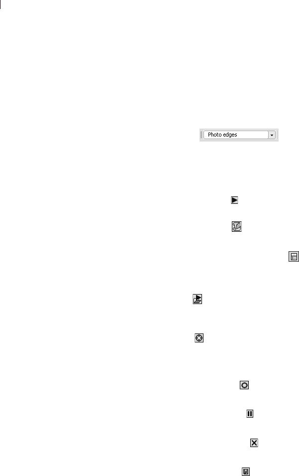
Chapter 17: Automating Tasks
426
About the Script Toolbar Buttons
Note
Most of the Script toolbar buttons have equivalent menu commands
accessed by choosing File > Script.
The items in the Script toolbar are:
Select Script By default, this drop-list shows
the scripts saved in Paint Shop Pro 9’s Scripts-Trusted and
Scripts-Restricted folders. Using the File Locations dialog, you
can add any folder to the list of folders that this drop-list displays
scripts from.
Run Selected Script Click this button to run the script
displayed in the Select Script drop-list.
Edit Selected Script Click this button to edit the script
displayed in the Select Script drop-list.
Interactive Script Playback Toggle Click this button to switch
between Silent and Interactive mode when running scripts. When
the button shows a border, it is set to Interactive mode.
Run Script Click this button to display the Run Script dialog.
Navigate (if necessary) to and select the script you wish to load,
and then click Open.
Stop Script Click this button to stop the running script.
Note: This button will only be active while the script is
running.
Start Script Recording Click this button to begin recording
actions that will comprise a script.
Pause Script Recording Click this button to pause the
recording of a script. Click this button again to resume recording.
Cancel Script Recording Click this button to cancel script
recording.
Save Script Recording Click this button to save the actions
you have recorded.
Note: This button is only active if you have completed a
“scriptable” action.

Chapter 17: Automating Tasks 427
About the Script Output Palette
To display this palette, choose View > Palettes > Script Output. This
palette may automatically appear to display information such as
script error information, including details on Python syntax errors or
runtime errors.
To clear the Script Output palette:
Choose File > Script > Clear Output Window or right-click the
window and choose Clear from the context menu.
Running a Saved Script
To run a script listed in the Select Script drop-list:
1 Select the script that you want to run from the drop-list.
2 Click Run Selected Script .
To run a script not listed in the Select Script drop-list:
1 Click Run Script to display the Run Script dialog.
2 Navigate to the folder containing the script that you want to run.
3 Select the script and click Open to execute the script.
Stopping or Undoing a Script
To stop a running script:
Click Stop Script .
Note: The Stop Script button is only active while the script is
running. Depending on the script, this may only be a few
seconds.
To undo an applied script:
Like any other action applied to an image, you can always undo an
applied script by clicking Undo on the Standard toolbar. You can
also undo actions via the History palette.
Script Output tip
Text in the Script Output window
can be selected and copied to the
clipboard. This can be helpful if
you need to report error
information.
To run a script on all open
images:
Using one of the methods on the
right, run the script on the first
image. Make another image active,
and then press Ctrl + Y. Repeat
this for each open image. You
could also drag the script action
from the History palette and drop it
onto another open image.

Chapter 17: Automating Tasks
428
About Restricted Script Mode
The scripts in Paint Shop Pro 9 are created in the Python
programming language, which can unfortunately be used to create
and execute malicious scripts. Because of this potential danger, Paint
Shop Pro includes two explicit directory sets:
Scripts - Restricted Scripts residing here are restricted, as are any
scripts not in the Trusted folder (see Restriction information
below).
Scripts - Trusted Scripts residing here are trusted.
What is Restricted?
Some general notes about Restricted scripts:
When the application searches for scripts, Restricted scripts are
searched before Trusted scripts. In the Script toolbar’s Select
Script drop-list, the two sets of scripts are intermingled and listed
alphabetically.
When saving a script, the path defaults to the Restricted directory
for the first time this is done with the application. After that, it
defaults to the most recently used directory.
If a script is run from an unconfigured path, it is treated as
Restricted.
If a path appears in both the Restricted and Trusted lists, it is
treated as Restricted.
Presets, Material palette Swatches, and Print Layout Templates
(which are essentially scripts) are treated as Restricted.
Additionally, the following commands are not allowed when run
from a Restricted script:
File: Save, Save As, Save Copy As, Close, Close All, Send, Exit
File > Export: GIF Optimizer, PNG Optimizer, JPEG Optimizer,
Image Mapper, Image Slicer
File > Preferences: File Locations
File > Batch: Process, Rename

Chapter 17: Automating Tasks 429
Toggling Interactive Script Playback
Mode
When you have scripted actions that involve dialogs, you can choose
to run the script so the dialogs will not appear (this is Silent mode)
for user interaction, or the dialogs will appear (this is Interactive
mode) for user interaction. To toggle between Interactive and Silent
script playback mode, simply click the Interactive Script Playback
Toggle button on the Script toolbar. When the button has a
border around it, it is in Interactive mode.
Note: If you’ve edited the script and set part or all of it to run in
either Silent or Interactive mode, this button will not override
that setting. If all or part of a script is set to Default mode, the
state of this button will override the Default setting.
Recording and Saving a Script
Before you begin recording a script, be aware of these general rules
as to which actions can be recorded within Paint Shop Pro 9:
You cannot script user interface customizations, CMYK profile
creation/editing, operations inside the Browser, operations inside
of Print Layout, gradient creation, or the floating/docking/
arranging of toolbars, palettes and windows.
Materials palette and Mixer palette operations as well as Tool
Palette selections can be scripted but are not recorded — these
actions need to be written via a text editor application. Plug-ins
are scriptable, but plug-ins that do not support scripting cannot
be scripted.
Outside of the above restrictions, most actions you perform in
Paint Shop Pro are scriptable.
To record and save a script:
1 Make a note of or write down the specific actions you wish to
record. Ideally, your actions should be as efficient as possible.
2 To begin recording, click Start Script Recording .
3 Perform the actions that comprise the script.
4 Click Save Script Recording . In the Save As dialog, do the
following:
Scripting rules of thumb:
The longer a task takes to
complete, the more desirable it is
to have a script for it. However, if a
task only takes two or three mouse
clicks to complete, creating and
running a script for those few
actions may not save you any time.
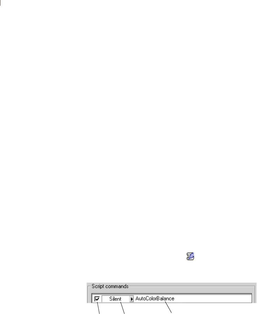
Chapter 17: Automating Tasks
430
If you chose to undo any actions while recording the script,
you can choose to retain (by not marking) or remove (by
marking) undone commands via the Remove Undone
Commands check box located toward the bottom of the Save
As dialog.
Mark the Save Materials check box if you wish to save the
Materials palette settings used by the scripted actions. If you
do not mark this option, affected commands will use the
current Materials palette settings.
Mark the Save Dialog Positions check box to display
interactive dialogs in their position during recording.
Optionally, you can click the Description button to enter
Author, Copyright, and Description information. The
information you enter will be seen if you chose to edit the
script.
5 Navigate (if necessary) to where the script will reside, enter a
name for the script, and then click Save.
Editing Scripts
Scripts can be edited via the Paint Shop Pro user interface, or by
editing the script’s Python code with a text editor application.
Editing Scripts Using Paint Shop Pro
To edit the currently selected script:
1 Click the Edit Selected Script button . The Script Editor dialog
will appear, listing the actions that comprise the script, as well as
some basic information. Shown below is a portion of the dialog.
Note: If the script you wish to edit is not in the Select Script
drop-list, choose File > Script > Edit to display the Open dialog.
Navigate to where the script resides. When you open the script,
its information will appear in the Script Editor dialog.
Mark to use
command Select a Mode for
the command actions Click the command or feature
to modify its settings

Chapter 17: Automating Tasks 431
Note: If the Script Editor cannot open the script (e.g. the format
is unreadable, or perhaps the script was created or edited
manually in a text editor), the script will open in the default text
editor application set in the File Locations dialog. Refer to the
section “Editing Via a Text Editor” below.
2 In the Scripts Commands section, you can do the following:
Mark the check box to use that portion of the script.
Use the Mode drop-list to set a mode for the script’s actions:
Silent Skip all dialogs. The command in the script is executed
without providing the user dialog interaction.
Interactive Allows for user interaction with dialogs and other
settings.
Default Executes the command based on what the execution
environment has set for its preference.
To display and/or modify a command’s settings, select the
command and then click Edit, or double-click the command.
Be aware that command names show in italics with the words
“NOT editable” cannot be selected for editing.
Note: There are a small number of commands that can only be
edited when an image is open in the workspace.
To remove commands from the script, select the command
and click Delete. To select multiple commands, use the
standard Shift-click (to select adjacent items) or Ctrl-click (to
select non-adjacent items) methods.
3 To view and/or edit the Python code associated with the script,
click the Text Editor button. The default text editor will open the
script. Until you specify another application, the default editor is
Notepad. To change the default text editor, see “Editing Scripts
with a Text Editor” below.
4 To save your edits, click Save, and then click Close.
Editing Scripts with a Text Editor
With the Script Editor dialog displayed, you can edit the Python
code for your script by clicking the Text Editor button. (If you have
already modified the script in the Script Editor dialog, you will be
prompted to save or discard changes prior to switching to the text
editor application.) The editor application designated for script
editing will open.

Chapter 17: Automating Tasks
432
To change the script editing application:
1 Choose File > Preferences > File Locations (or click the File
Locations button in the Select Script drop list) to open the File
Locations dialog.
2 In the File Types list, choose Python Source Editor.
3 On the right side of the dialog, enter the path for the editor
application you wish to use. Click Browse if you need to navigate
for the correct path.
Trouble Shooting a Script
The Single Step command (accessed by choosing File > Script >
Single Step) provides a way to sequentially step through a script's
actions, allowing you to selectively apply actions to the current
image.
Single Step can be thought of as a mode or a toggle: once you choose
this menu item, scripts you run will be put through the Single Step
"filter" until you toggle off the mode by choosing the menu item
again.
To use this command:
1 Choose File > Script > Single Step. This puts Paint Shop Pro in
Script Single Step mode. Note that the Step Script dialog will not
appear until you choose to run a script.
2 Run the desired script.
3 The Step Script dialog appears, listing the script's name and first
action. Use the dialog's buttons as follows:
Click Continue to apply the command to the image and move
on to the next command in the script.
Click Skip Command to not apply this particular command to
the image, and instead move on to the next command in the
script.
Click Stop Scripts to cancel this operation and close the Step
Script dialog. Note, however, that Paint Shop Pro remains in
Script Single Step mode until you toggle off this command.
4 To turn off Single Step mode, choose File > Script > Single Step
again.
Access Single Step quicker
If you find yourself using the Single
Step command often, you may
want to add it to a toolbar for
quicker access. Refer to Chapter 4
for more information on
customizing toolbars.
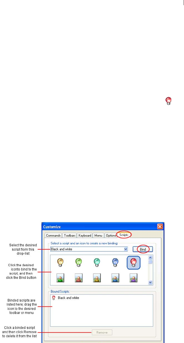
Chapter 17: Automating Tasks 433
Binding Scripts to Icons
You can quickly and easily bind a script to any of 50 icons, and then
drag the icon to a custom or existing toolbar, or to a menu. By
dragging the icon onto a toolbar or menu you can have easier,
quicker access to your favorite scripts, and can execute them with a
single click.
Be aware that you can use an icon for any number of scripts. This
gives you a virtually limitless ability to bind scripts to icons. For
example, you could assign a script to the red light bulb icon and
drag it to the Photo toolbar. You could then assign a different script
to the same icon and drag it to the Adjust menu.
Assigning a Script to an Icon
1 Choose View > Customize. This displays the Customize dialog.
2 Click the Scripts tab.
3 Click the Scripts drop-list, and then click the script you want to
assign to an icon. (Note that the scripts displayed in this list
match those in the Script toolbar's Select Script drop list.)
4 Shown below the Scripts drop-list are the 50 icons. To assign the
displayed script to an icon, click the desired icon, and then click
the Bind button in the upper right portion of the Scripts tab.
Notice in the Bound Scripts area below, the icon and its
associated script appear in the list.
Assigning a keyboard
shortcut to a Bound Script
Once you’ve created a bound
script, you could assign a keyboard
shortcut to it as another way to
quickly run the script. Refer to
Chapter 4 for information on
assigning keyboard shortcuts.

Chapter 17: Automating Tasks
434
5 To place the icon in a menu or toolbar:
In the Bound Script area, place the cursor over the icon or the
script.
Drag the mouse into the menu or toolbar where you want to
place the bound script icon.
Release the mouse button when the button is in the desired
location.
When you hold the cursor over the toolbar's script icon, you'll see
the path name and file name associated with the script. If you've
dragged the script icon into a menu, the menu will display the
script's name, and the script's path will appear in the status bar
located along the bottom the main Paint Shop Pro window.
Using the Same Icon for Multiple Scripts
Although there are 50 icons available for script assignments, be
aware that you can use the same icon for multiple scripts. This
essentially gives you an unlimited ability to assign scripts to icons.
Removing a Script from an Icon
To un-bind a script from an icon:
1 In the Bound Script area of the Customize dialog's Scripts tab, click
the icon or script name.
2 Click the Remove button located below the Bound Scripts list.
Note: Unbinding a script from an icon will also remove it from
the user interface and from any keyboard shortcut assigned to it.
Removing a Bound Script from a Menu or Toolbar
To remove a bound script icon from a menu or toolbar, place the
cursor over the icon, drag the icon into the Paint Shop Pro
workspace, and then release the mouse button.

435
Printing Images
With Paint Shop Pro you can print one image on a page, print several
images on a page, or print selected images within a folder. You can
also create templates that save the size and placement of images, and
add text captions to the template.
There are several ways to print in Paint Shop Pro:
Print a single image. For more information, see “Printing
Multiple Images on a Page” on page 439.
Print multiple images on one page. Arrange and size images in
any way you like. Choose from over 100 templates, or create
your own custom template. For more information, see “Printing a
Single Image” on page 446.
Print images from the Browser as thumbnails or in any
arrangement. For more information, see “Printing with CMYK
Color Separations” on page 452.
Contents About Printing . . . . . . . . . . . . . . . . . . . . . . . . . . . . . . . . . . . . . 436
About Printing Options. . . . . . . . . . . . . . . . . . . . . . . . . . . . . . . 437
Printing Multiple Images on a Page . . . . . . . . . . . . . . . . . . . . . 439
Printing a Single Image . . . . . . . . . . . . . . . . . . . . . . . . . . . . . . 446
Printing Images from the Browser. . . . . . . . . . . . . . . . . . . . . . . 446
Printing Images Using a Template . . . . . . . . . . . . . . . . . . . . . . 448
Placing Text Captions on the Layout. . . . . . . . . . . . . . . . . . . . . 451
Printing with CMYK Color Separations . . . . . . . . . . . . . . . . . . . 452
Saving Images for Printing. . . . . . . . . . . . . . . . . . . . . . . . . . . . 456
CHAPTER 18

Chapter 18: Printing Images
436
About Printing
Before you print, you should understand how image resolution, color
and lightness, paper quality, and the file type of the image effect the
quality of the printed image.
Image Resolution
Laser and ink-jet printers work by applying dots of black or colored
ink to paper. While the image resolution is measured in pixels per
inch (ppi), the printer resolution is measured in dots per inch (dpi).
To determine the printed image size in inches, the printer divides the
image size in pixels by the pixels per inch. An image with a high
resolution appears smaller when printed at its original size than an
image with a low resolution.
You can scale images when you use Print Layout to print multiple
images. However, this can lower the quality of the print, as it
enlarges each pixel. You will get better results if you create the
image using a resolution that is appropriate for the printer. Use the
following guidelines to determine the image size for printing:
For a 300 dpi printer, use a 72 to 120 ppi image.
For a 600 dpi printer, use a 125 to 170 ppi image.
For a 1200 dpi printer, use a 150 to 200 ppi image.
Image Color and Lightness
Computer monitors display color by combining red, green, and blue
light on the screen. Color printers, however, use a combination of
cyan, magenta, yellow, and black inks. The difference in these two
color modes can cause images to appear darker on paper than on the
screen. As you become familiar with how your printer handles color,
adjust your images to compensate. If the printed image appears too
dark, use the Brightness/Contrast command to adjust it.
Paper Quality
The texture and color of the paper affects the quality of the printed
image. Porous paper can cause colors to bleed into each other;
colored paper can alter the image colors; off-white paper can reduce
the contrast and vibrancy of colors. For the best results, refer to your
printer’s owner manual for paper recommendations.

Chapter 18: Printing Images 437
Saving Images for Printing
If you are printing your image on a personal printer, save it in the
.PspImage format. This gives you the most flexibility. Paint Shop
Pro prints all the layers in an image, so you don’t need to flatten it
(merge all layers). If you are using a black-and-white printer, choose
the Greyscale option in the Print dialog.
If you are sending the image to a printing service, flatten the image
before saving it. When you save an image in most formats other than
.PspImage, Paint Shop Pro automatically flattens the image. Ask
your printer about the requirements for file format, resolution, and
color depth. If you need CMYK color separations, choose that
option in the Print dialog.
About Printing Options
To open the Print Setup dialog, from the main Paint Shop Pro
workspace, choose File > Print, or press Ctrl + P. From the Print
Layout window, choose File > Print Setup, or click the Print Setup
button.
Note: Note: You can script most print options. However, all
printer settings may not be scriptable due to variations in printer
drivers.
The following printing options are available when printing a single
image. Most of the options are also available when printing multiple
images from the Print Layout window.
Choosing print setup options:
1 In the Printer group box, choose the printer to send the image to.
Click the Printer button to select a different printer. Click the
Properties button to view or change printer properties. For more
information, refer to your printer documentation.
2 Print to File Mark this check box to save the image to a file
instead of sending it to a printer. When you click the Print button
to print the image, Paint Shop Pro prompts you for a file name.
3 Enter the number of copies to print in the Number of Copies field.
4 In the Orientation group box choose either the portrait or
landscape orientation.
How to access Print options
From the main Paint Shop Pro
workspace, choose File > Print, or
press Ctrl + P.
From the Print Layout window,
choose File > Print Setup, or click
the Print Setup button.

Chapter 18: Printing Images
438
5 In the Print Output group box, choose the type of output: Color,
Greyscale, or CMYK Separations. For more information on
printing CMYK color separations, see “Printing with CMYK
Color Separations” on page 452.
6 In the Color options group box, choose an option:
Negative Mark this check box to print a negative of the image.
Background Mark this check box to print a color background
around the image, and then click the color box to choose the
background color.
7 In the Print Marks group box, choose from the following options:
Corner Crop Marks Mark this check box to print crop marks at
the corners of the image.
Center Crop Marks Mark this check box to print crop marks at
the center of the image edges.
Registration Marks Mark this check box to print registration
marks at the corners of the image.
CMYK Plate Labels Mark this check box to print labels (Cyan,
Magenta, Yellow, or Black) on each color plate (or page). This
check box is available only when you select the CMYK
Separations option.
Image Name Mark this check box to print the image file name
below the image.
8 Mark the Header check box to include header text at the top of
the page, and then type the text in the edit box.
9 Mark the Footer check box to include footer text at the bottom of
the page, and then type the text in the edit box.
10 Click Close to apply the settings and close the Print Setup dialog.
Scripting print options
You can script most print options.
However, all printer settings may
not be scriptable due to variations
in printer drivers.

Chapter 18: Printing Images 439
Select Template (Print dialog only) Click this button to open the
Templates dialog and choose a template. For more information on
choosing templates, see “Printing a Single Image” on page 446.
Fill the template with the current image (Print dialog only) Choose
this option to fill the selected template with the current image.
Print the selected template with saved images (Print dialog only) If
you select a template that contains links to images, the current image
will be ignored and the template and all its images will be printed.
Header (Print Layout window only) Mark the check box to include
header text at the top of the page, and then type the text in the edit
box.
Footer (Print Layout window only) Mark the check box to include
footer text at the bottom of the page, and then type the text in the edit
box.
Printing Multiple Images on a Page
Use Paint Shop Pro’s Print Layout window to print multiple images
in a variety of ways. For example, print multiple 4” x 6” copies of
the same image, print two different images on the same page, or
arrange an image to print on labels. You can even add text captions
onto the print layout, and place images in rectangular or elliptical
cells.
Note
After you arrange a layout, save the layout as a template that you can
use later. For more information, see “Saving a Page Layout” on
page 445. Paint Shop Pro includes many templates to use or modify.
For more information, see “Printing a Single Image” on page 446.
How to change the
paper size
The paper size (such as letter or
legal) is a printer property. At the
Print window or the Page Setup
window, click the Properties
button, then the Paper tab.
Template printing is
scriptable.
The Print command and the
Template tab settings can be
recorded in a script.
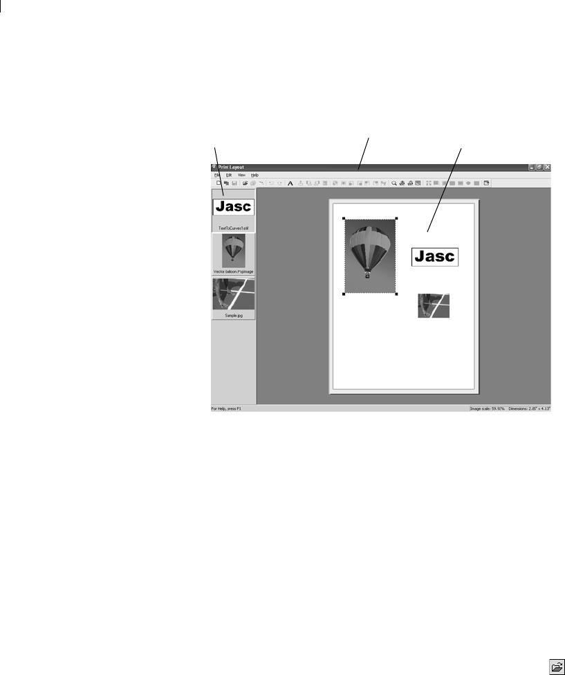
Chapter 18: Printing Images
440
About the Print Layout Window
To print images using the Print Layout Window:
1 Open the Print Layout window:
From the Paint Shop Pro workspace, open each of the images
you want to print, and then choose File > Print Layout.
From the Paint Shop Pro Browser, select the thumbnail of
each image you want to print, and then choose File > Print
Layout.
Thumbnails of all open images display on the left side. The page
layout to be printed displays in the center of a gray area (the print
layout workspace).
Note: To select more images from the Print Layout window,
choose File > Open Image or click the Open an Image button .
2 Drag the thumbnails of the images you want to print into the print
layout. If an image is larger than the page, Paint Shop Pro asks
whether you want to scale the image. Click Yes to scale the
image to fit, or click No to place the image at its current size.
Thumbnails Layout
Print Layout Window
Where did the image go?
The print layout workspace
extends under the thumbnail list.
Zoom out or use the scroll bars to
see if your image is hidden under
the thumbnail list.
Chapter 18: Printing Images 441
Note: To locate an image that is out of view in the Print Layout
window, use the scrollbars to scroll through the workspace and
locate the image, or choose Preferences > Auto Arrange. Paint
Shop Pro arranges all images in the workspace onto the page. If
the image is still out of view, choose Zoom > Zoom to Page.
3 Choose File > Print, or press Ctrl + P to open the Print dialog, or
click Print to print the page with the current print settings.
Note: To adjust print settings, choose File > Print Setup or click
the Print Setup . For more details, see “About Printing
Options” on page 437.
4 To close the Print Layout window, choose File > Close or click
the Close button .
Note
To remove an image from a print layout, click the image to select it,
and then press Delete, or choose Image > Remove.
Arranging and Sizing Images in a Layout
Once you have images open in the Print Layout window, you can
automatically or manually arrange images in a layout.
Automatically Arranging Images in a Layout
Use the Auto Arrange command to automatically size and position
images on the page of the Print Layout window. Paint Shop Pro
divides the page into sections of equal size and places each image in
a section. Only images on the page or in the workspace are used.
Before automatically arranging images, specify these preferences:
To include borders between arranged images, choose View >
Options to set up border options width (the default is 0.5 inches
or 1.27 centimeters). If you do not use borders, Paint Shop Pro
may arrange images with touching edges.
To have Paint Shop Pro enlarge (stretch) images to fit their
sections of the page layout, choose View > Stretch to Fit or click
the Stretch to fit button . If you do not choose this option,
when Paint Shop Pro automatically arranges photos, it keeps
them the same size or, if necessary, makes them smaller to fit.
Manually Arranging and sizing Images in a Layout
Use rotate, resize, position, or zoom the images. Display the grid if
you want to precisely position image in the window.
Using the Zoom tools:
To zoom in on a specific area,
click the Zoom to Rectangle
button . Then click and drag
within the page layout to choose
an area to zoom in on (make
sure you click on a blank part of
the page to begin).
To zoom in, click Zoom In 10% .
To zoom out, click Zoom Out
10%.
To make the page layout fill the
workspace, click
Zoom to Page .
You can also choose any of these
commands from the Zoom menu.
Save layouts
You can save layouts as templates
to make page layout easier. Paint
Shop Pro also includes many
templates with common layouts.
For more information, see “Saving
a Page Layout” on page 445 and
“Printing a Single Image” on
page 446.
Chapter 18: Printing Images
442
To automatically arrange images:
1 Drag each image that you want to arrange onto the page or the
workspace.
2 Choose Preferences > Auto Arrange, or click the Auto Arrange
button .
To rotate an image:
1 Click the image to select it. To select multiple images, press Shift
and click each additional image.
2 On the toolbar, click Rotate Clockwise 90 or Rotate
Counterclockwise 90 . Or, select the same commands from
the Edit menu.
To resize an image:
1 Click the image to select it.
2 Resize manually or via the Resize dialog:
To resize manually, drag a corner handle until the image is the
size you want it. The image maintains its aspect ratio.
Click the Resize button on the toolbar, or choose Edit >
Resize. Use the Resize dialog options to set the desired size.
To position an image:
Click and drag the image to a new position on the page. You can also
temporarily place images in the workspace around the page.
You can also position an image by clicking one of the command
buttons. These buttons align the selected image to the layout page.
Position image at X,Y Click this button to open the Place Image
dialog. Enter values to set the position of the image’s top left corner.
Using the Grid in a Layout
Use the grid to align images evenly on the page.
Notes on resizing
Resizing an image for printing can
result in poor image quality. When
you enlarge an image, the image
loses detail and sharpness. As a
general rule, don’t enlarge or
reduce an image more that about
25 percent. If you need more than
a 25 percent change, scan or
create the image at a different
resolution.
Center image
Place lower left
Place lower right
Place upper left
Position image at X,Y
Place upper right

Chapter 18: Printing Images 443
To display or hide the grid:
Choose View > Show Grid.
To snap images to the grid:
1 Display the grid.
2 Choose View > Snap to Grid.
When you click and drag an image to position it, Paint Shop Pro
snaps it to the nearest grid line when you release the mouse.
To change the grid settings:
1 Choose View > Options to open the Print Layout Options dialog.
2 Set the grid options on the right side of the dialog. For more
information see “In the Grid settings group box, set the following
options:” on page 444.
3 Click OK.

Chapter 18: Printing Images
444
Changing Print Layout Window Options
Use the options in the Print Layout dialog to set auto arrange
options, units of measurement, grid settings and template options.
To change Print Layout window settings:
1 In the Print Layout window, choose View > Options to open the
Print Layout Options dialog.
2 Choose the Units, either inches or centimeters from the drop
down list. The dialog’s measurements will change to match.
3 Mar the Center to full page check box to have Paint Shop Pro
calculate the page center based on the actual size of the page.
Clear this check box to have the page center calculated based on
the printer’s margins.
4 In the Auto Arrange group box, choose from the following:
Use borders Mark this box to have the Auto Arrange function
leave a specified border around all images. Enter values for
the horizontal and vertical border sizes.
Stretch to fit Mark this box to have the auto arrange function
enlarge images as much as possible (while keeping their
aspect ratios).
Horizontal and Vertical border size Sets the size of the border
using the units option chosen above.
5 In the Template options group box:
Choose the Default Placement to determine how images will
be placed in template cells by default.
Mark the Apply to current template check box to apply the
new default placement option to all the cells of the open
template.
6 In the Grid settings group box, set the following options:
Show Grid Mark the check box to show the grid, or clear it to
hide the grid.
Dot Grid Mark the check box to use a dotted-line grid, or clear
it to use a solid line grid.
Grid Color Click the color box to choose another color for grid
lines.
Horizontal Spacing Sets spacing between horizontal grid
lines.

Chapter 18: Printing Images 445
Vertical Spacing Sets spacing between vertical grid lines.
Snap-to-Grid Mark the check box to snap images to grid lines
when you position them. Clear the check box to position
images freely on the page.
Saving a Page Layout
After you set up a page layout, you can save it. You can also save
just the formatting of your layout to use with other images. Paint
Shop Pro saves the layout as a template.
By default, templates you save are stored in the Print Templates
folder of the My Documents\My PSP Files folder.
You can save your layouts in two ways: as a template or as a
template with images.
Templates
By default, Paint Shop Pro saves your layout as a template. When
you save your layout, Paint Shop Pro uses the size and position of
the images in your layout to create blank cells for new images to be
placed in. When you open the template later, you must place new
images into the blank cells.
Templates with Images
For a layout with certain images that you want to print repeatedly,
save the layout as a template with links to the images. Every time
you open the template, it will open and display the images you
placed in your layout. If you modify images linked to a template, the
modified images will appear the next time you open the template.
To save a layout:
1 Choose File > Save Template or click the Save Template button
to open the Save dialog.
2 Enter a name for the new template in the Name field.
3 Choose a save option:
Mark the Save with Images check box to save image links
with the template. When you open the template the images
currently on the page will appear. Clear this check box to
create a blank template.

Chapter 18: Printing Images
446
4 Click OK.
Note
To delete a print layout, use Windows Explorer to navigate to where
the template resides, and then delete the layout from the folder.
Printing a Single Image
To print the active image:
1 Choose File > Print, click Print , or press Ctrl + P to open the
Print dialog.
2 Do any or all of the following:
In the Printer group box, select the printer and whether to
print to file.
On the Placement tab, choose the number of copies, the page
orientation, and the size and position of the image.
On the Options tab, choose the print output, color options, and
print marks.
On the Template tab, choose to print a template with images
or fill a template with the current image.
Selected options display on the image preview. For more
information on the options, see “Printing a Single Image” on
page 446.
3 Click the Print button to print the image. Or, click the Close
button to save the print options without printing the image.
Printing Images from the Browser
Use the Paint Shop Pro Browser to print all images within a folder,
or only selected images. Print the images as thumbnails, or print
them any size using a template.
When you print from the Browser, Paint Shop Pro automatically
includes the file name under each image, as well as the folder name
at the top of the page, and a page number at the bottom.
To print images from the Browser:
1 Choose File > Browse or press Ctrl + B.
The Browse window opens and the main menu updates with
Browse commands.
Quick steps for printing
Press Ctrl + P to open the Print
dialog, then press Enter.

Chapter 18: Printing Images 447
2 Navigate to the folder that contains the files you want to print.
3 Select files using one of these methods:
Click the file’s thumbnail.
To select more than one file, press Ctrl and click each file.
To select sequential files, click the first file, then press Shift
and click the last file.
Note: To deselect a file, press Ctrl and click its thumbnail.
4 Choose File > Print to open the Browser Print dialog.
5 Choose options from the Printer and Copies group boxes.
For more information, see “Printing a Single Image” on
page 446.
6 Choose a thumbnail option:
Use Thumbnails Mark the check box to use thumbnail images,
which print faster but are lower resolution and fuzzy. Clear the
check box to print the images at normal resolution.
7 Choose template options:
Use the standard template
Mark this box to print all the images at thumbnail size.
Clear this box to choose a template from the drop down list.
The Browser will use the template to format your images for
printing. To change the folder where Paint Shop Pro loads
templates from, click the Edit Paths button. For more
information, see Chapter 4, Setting File Format Associations.
8 Choose a Print Range option:
All Prints all the pages the Browser has created for printing.
Pages Prints only the page range you enter in the from and to
fields.
Selection Prints only the images you selected in the Browser
window instead of all the images in the current folder.
9 Click the Print button to print. Or, click the Close button to save
the print options without printing the images.
Chapter 18: Printing Images
448
Printing Images Using a Template
Use templates to simplify image placement and sizing. Templates,
by default, do not contain any specific images. However, Paint Shop
Pro can save templates with links to images.
Save your own templates (created from page layouts) or use any of
Paint Shop Pro’s many templates.
By default, sample templates are stored in the Print Templates folder
of Paint Shop Pro program folder. To change where Paint Shop Pro
stores and searches for templates, click the Edit template file
locations button or choose File > Template locations. For more
information, see Chapter 4, Setting File Format Associations.
To print images using a template:
1 Open the Print Layout window:
From the Paint Shop Pro workspace, open each of the images
you want to print, and then choose File > Print Layout.
From the Paint Shop Pro Browser, select the thumbnail of
each image you want to print, and then choose File > Print
Layout.
Each open file is displayed in the thumbnail list on the left side.
A blank layout is displayed.
2 In the Print Layout window, choose File > Open Template or
click Open Template to open the Templates dialog.
3 Choose a category from the Select a category list. Thumbnails of
the templates in each category are shown in the window to the
left. Templates that have images saved with them will show
colored template cells.
Note: When you save custom templates, they will appear under
the User Defined category.
4 Select the thumbnail of the template you want to open.
5 Click OK. Paint Shop Pro displays the template in the Print
Layout window.
Note: If you saved images with the template, the images will
appear in the template cells and in the thumbnail list. Templates
that have images missing will display a greyed out cell in the
template thumbnail.
6 In the Print Layout window, choose File > Open Template or
click Open Template to open the Templates dialog.
To open the Print Layout
window
At the Paint Shop Pro main menu,
choose File > Print Layout.
This command is only available
when at least one image is open in
Paint Shop Pro.
A quick way to print with
templates from the
main workspace
The Template tab of the
File > Print command allows you
to fill templates with the current
image and print templates with
saved images. These actions are
also scriptable. For more
information on the Print to
Template option, see “Printing a
Single Image” on page 446.
Template Hint
You can also open a template by
double clicking its thumbnail.
Chapter 18: Printing Images 449
7 Choose a category from the Select a category list.
8 Select the thumbnail of the template you want to delete. Click
Delete.
9 Place images into the cells in the template:
Place multiple images by dragging each thumbnail into a
template cell.
Fill the template with copies of the same image, by dragging
one image thumbnail onto any cell and then choosing Edit >
Fill Template with Image or clicking the Fill template with
image button .
Paint Shop Pro fills all cells with the image.
Note: By default, Paint Shop Pro centers the image within the
cell and scales the image to fit the cell. To change the default
placement method, see “In the Template options group box:” on
page 444.
10 Choose a cell placement method from the Print Layout window
toolbar or from Edit > Cell Placement.
Note: You can select the image placement method of a cell before
or after you place an image.
Free format Allows you to freely resize and position the
image in the cell.
Size and Center The image size is not changed to match the
cell. You can resize the image and the image will always stay
centered in the cell.
Fill Cell with the image Centers the image in the cell and
scales the image to fill the cell. The image aspect ratio is
maintained, but parts of the image may not be visible.
Fit and center Scales the image to fit entirely inside the cell
and centers the image in the cell. The image aspect ratio is
maintained.
Fit and adjust left Scales the image to fit entirely inside the
cell and aligns the image to the left side of the cell. The image
aspect ratio is maintained.
Fit and adjust right Scales the image to fit entirely inside the
cell and aligns the image to the right side of the cell. The image
aspect ratio is maintained.
Fit and adjust top Scales the image to fit entirely inside the
cell and aligns the image to the top of the cell. The image aspect
ratio is maintained.
Quick steps to printing
multiple copies of the
same image
Open a template, drag one image
into any cell of the template, then
choose Templates > Fill
Template with Image. Paint Shop
Pro places the same image in
every cell. Now choose File >
Print.

Chapter 18: Printing Images
450
Fit and adjust bottom Scales the image to fit entirely inside
the cell and aligns the image to the bottom of the cell. The image
aspect ratio is maintained.
To move, rotate, and resize images in cells:
Follow the instructions in “Choose Preferences > Auto Arrange, or
click the Auto Arrange button .” on page 442.
To remove an image from a template:
1 Click the image to select it.
2 Press Delete, or choose Edit > Remove.
Editing Template Cells
You cannot move or resize cells in a template. A cell’s position and
size is locked when a layout is saved as a template.
However, if you saved images with a template, you can revert the
template back to a layout.
To revert a template (with images) to a layout:
1 Open the template you want to edit. For more information, see
“Printing a Single Image” on page 446.
2 Choose File > New Template or click the New Template button
. A dialog will open asking, “Do you want to keep the current
images in the new template?”
3 Click Yes.
The Print Layout window will display a new layout that contains
all the images that were in the template.
Editing Multiple Cells Simultaneously
Print Layout allows you to apply modifications to multiple cells at
the same time. To do so:
1 Select the desired cells. Drag the cursor to enclose the cells in a
bounding box, or hold down Ctrl and click the cells you want to
select. When selected, the cell border will turn red.
2 Apply the desired edit to the cells. Use the commands in the Edit
menu or those in the Print Layout toolbar.
Placing images from the
thumbnail list
To control how Paint Shop Pro
places an image when you drag it
from the thumbnail list, change the
template options. For more
information see, “In the Template
options group box:” on page 444.

Chapter 18: Printing Images 451
Creating an Elliptical Image Cell
To change a cell from rectangular to elliptical:
1 In Print Layout, load a template containing at least one cell.
2 Click the cell you want to make elliptical, and then click the
Make cell elliptical button on the Print Layout toolbar, or
choose Edit > Set selected cells elliptical. The cell's image will
then appear through the ellipse.
Note: To make the cell rectangular again, click the Make cell
rectangular button , or choose Edit > Set selected cells
rectangular.
Placing Text Captions on the Layout
To place a box containing custom text onto your print layout:
1 In the main Paint Shop Pro workspace, open the image(s) you wish
to print.
2 Choose File > Print Layout. This puts Paint Shop Pro in Print
Layout mode. Your open images will appear along the left side of
the window.
3 Drag the images into the layout area on the right, or load an
existing template and drag your images into the template's cells.
4 In the Print Layout toolbar, click the Text tool .
5 Position the cursor where you want the text to appear, and then
drag the cursor to create the text box. When you release the
mouse button, the Text Field dialog will appear.
6 Enter the text you want to appear on the printed page.
7 Set your options for font, size, style, color, and alignment. Note
that if you want to continue using these settings, mark the Retain
text settings check box at the bottom of the Text Field dialog.
8 Click OK to place your text on the layout.
9 If necessary, drag the sides of the text box to fit the text it
contains. Drag the text box to move it.
10 To rotate the text, select the text box (if it isn't already selected),
then choose Edit > Rotate Clockwise 90 / Rotate
Counterclockwise 90. You could also click these buttons on the
toolbar, or right-click and choose either rotation command from
the context menu.

Chapter 18: Printing Images
452
Printing with CMYK Color Separations
When you print using CMYK separations, Paint Shop Pro prints four
pages representing the levels of Cyan, Magenta, Yellow, and Black
in the image.
Note
Printing CMYK separations is the opposite of the Colors > Split
Channels > Split to CMYK command. When you split channels
Paint Shop Pro treats white as full color and black as no color
(brighter equals more color). When you print CMYK separations,
Paint Shop Pro treats black as full color and white as no color
(darker equals more color).
To modify the default CMYK conversion preferences, see “Defining
CMYK Profiles” on page 452
To print CMYK color separations:
1 Choose File > Print to open the Print dialog.
2 Click the Options tab.
3 In the Print Output group box, choose CMYK Separations.
4 Choose other print options as desired. For more information, see
“Printing a Single Image” on page 446.
5 Click the Print button.
Defining CMYK Profiles
In a CMYK (Cyan, Magenta, Yellow, and Black) conversion, Paint
Shop Pro replaces the RGB (Red, Green, and Blue) colors you see on
the monitor with the CMYK colors used in printing. You can then
print a separate page for each CMYK color by selecting the CMYK
Separations option in the Page Setup dialog box. This is useful if you
are using a pre press shop and doing high-end printing.
Before printing the separations, configure the CMYK preferences to
determine how Paint Shop Pro handles the conversion from RGB to
CMYK. Save these preferences in a file called a profile.
To set the current profile:
1 Choose File > Preferences CMYK Conversion Preferences to
open the CMYK Conversion Preferences dialog.

Chapter 18: Printing Images 453
2 Choose the name of the profile from the Current Profile drop
down list.
3 Click OK.
To create a new profile:
Note
Paint Shop Pro uses the program’s default settings until you create a
profile.
1 Choose File > Preferences > CMYK Conversion Preferences to
open the CMYK Conversion Preferences dialog.
2 Do one of the following:
Choose the name of a profile from the Current Profile drop
down list and click New. This will base the new profile on the
settings of the selected profile.
Click New. This will base the new profile on the program’s
defaults.
The New CMYK Profile dialog will open.
3 Type a name for the new profile in the Enter profile name field.
4 Choose the initial setting:
Reset to defaults Base the new profile on the program’s defaults.
Use current settings Base the new profile on the settings in the
current profile.
5 Click OK.
To remove a profile:
1 Choose File > Preferences > CMYK Conversion Preferences to
open the CMYK Conversion Preferences dialog.
2 Choose the name of the profile from the Current Profile drop
down list.
3 Click OK.
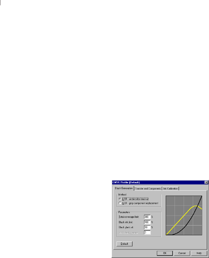
Chapter 18: Printing Images
454
Modifying a CMYK Profile
Use the tabs on the CMYK Profile dialog to configure the CMYK
black generation, transfer and components, and to adjust the for
color shifts.
To open the CMYK Profile dialog:
1 Choose File > Preferences > CMYK Conversion Preferences to
open the CMYK Conversion Preferences dialog.
2 Choose the name of the profile from the Current Profile drop
down list.
3 Click Modify to open the CMYK Profile dialog
Note
Clicking Default in any of the profile tabs will reset the tab to the
program’s default settings.
To configure the Black Generation tab:
1 In the CMYK Profile dialog click the Black Generation tab.
2 In the Method group box, choose from the following options:
UCR - Undercolor Removal Replaces some of the cyan, magenta,
and yellow components of neutral grey and shadow areas with
black. This helps compensate for some of the trapping problems
that occur in multi-color printing.
GCR - Grey Component Replacement Replaces grey components
in colored areas with black. The least prominent color is reduced
or removed completely, along with proportional amounts of the
other two colors, to define a grey component, which is then
replaced with black ink.
3 In the Parameters group box, configure the following settings:
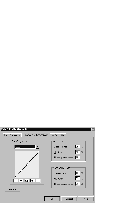
Chapter 18: Printing Images 455
Total coverage limit This can range from 200 to 400%
Blank ink coverage limit This can range from 0 to 200%
Black starts at This can range from 0 to 100%
GCR Black Gamma This can range from 1 to 4. This option is
inactive unless the GCR option is selected.
Note: The black line in the graph represents the black value and
updates as you change the settings.
To configure the Transfer and Components tab:
1 In the CMYK Profile dialog click the Transfer and Components
tab.
The left panel of the Transfer and Components tab displays a graph
of the transfer curves for cyan, magenta, yellow, and black. The
right panels display parameters for grey and color components.
2 In the Transfer Curves group box, adjust the transfer curves by
highlighting the name of a curve in the Transfer Curves drop-
down list, and then dragging the points of the curve up or down.
Each transfer curve contains five adjustable points that define the
curve based on its zero-tone, quarter-tone, mid-tone, three-
quarter-tone, and full-tone percentages. The default curve is a
straight line from 0 to 100%. A curve that slopes above this 45°
line produces darker tones.
3 In the Grey Component group box, set the percentages by typing
values into the corresponding fields. Values can range from 0 to
100%.
4 In the Color Component group box, set the percentages by typing
values into the corresponding fields. Values can range from 0 to
100%.
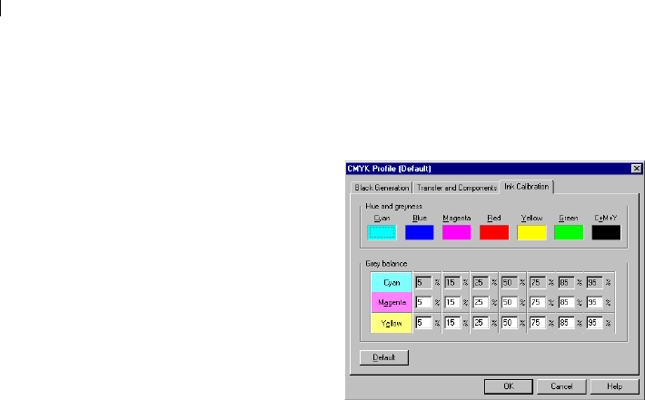
Chapter 18: Printing Images
456
To configure the Ink Calibration tab:
1 In the CMYK Profile dialog click the Ink Calibration tab.
2 In the Hue and Greyness group box, click in the color box of the
color you want to change to open the Color dialog. Adjust the
color settings and click OK.
3 In the Grey Balance group box , type values in the text fields to
adjust the individual CMY percentages.
Saving Images for Printing
If you are printing your image on a personal printer, save it in the
.PspImage format. This gives you the most flexibility. Paint Shop
Pro prints all the layers in an image, so you don’t need to flatten it
(merge all layers). If you are using a black-and-white printer, choose
the Greyscale option in the Print dialog.
If you are sending the image to a printing service, flatten the image
before saving it. When you save an image in most formats other than
.PspImage, Paint Shop Pro automatically flattens the image. Ask
your printer about the requirements for file format, resolution, and
color depth. If you need CMYK color separations, choose that
option in the Print dialog.

457
Sharing and Creating Images for the
Web
Use the Web tools to create backgrounds for your Web pages, map
and slice images to create hotspots or rollovers. Optimize images for
the Web to reduce the image file size and make images load more
quickly. Share your images by sending them via e-mail. Protect your
images by adding a watermark with creator and copyright
information.
Contents Sending Images via E-Mail . . . . . . . . . . . . . . . . . . . . . . . . . . . 458
Uploading Images to a Photo Sharing Service . . . . . . . . . . . . . 458
Saving Images for the Web . . . . . . . . . . . . . . . . . . . . . . . . . . . 459
Saving Images for Use In Animation Shop . . . . . . . . . . . . . . . . 470
Previewing Images in a Web Browser . . . . . . . . . . . . . . . . . . . 470
Creating Image Rollovers . . . . . . . . . . . . . . . . . . . . . . . . . . . . 471
Mapping Images . . . . . . . . . . . . . . . . . . . . . . . . . . . . . . . . . . . 472
Slicing Images . . . . . . . . . . . . . . . . . . . . . . . . . . . . . . . . . . . . 476
Using Digital Watermarks . . . . . . . . . . . . . . . . . . . . . . . . . . . . 480
CHAPTER 19

Chapter 19: Sharing and Creating Images for the Web
458
Sending Images via E-Mail
Use Paint Shop Pro to e-mail any open image to friends, family, or
colleague using an e-mail program. The image is in its current file
format whenever possible.
Note
In order to send images via e-mail your computer must have a
default e-mail application that supports the MAPI standard such as
Microsoft Outlook, or Outlook Express
To send the image via e-mail:
Choose File > Send or click the Send Mail button on the toolbar.
Your current mail program opens with the file attached. Enter the
recipient, type a message, and then send it.
Uploading Images to a Photo Sharing Service
Use Paint Shop Pro to easily upload your images to a photo sharing
service. Photo sharing services allow you to upload and store your
images online, order high-quality prints and greeting cards, and
share your images online.
Before you can add, share, and print pictures at a photo sharing
service, you must enroll. Signing up is free and gives you space to
store, print, and share your images. Visit the Web site for the photo
sharing to obtain your user name and password.
Uploading Images a Photo Sharing
Service
You can use Paint Shop Pro to upload images to a photo sharing
service.
To upload images to a photo sharing service:
1 Choose File > Browse or click the Browse button on the toolbar
to open the Paint Shop Pro Browser.
2 Select the images that you want to upload to a photo sharing
service.
Using other photo sharing
services
As Paint Shop Pro is updated,
support for additional photo
sharing services may be included.
To find out if support for additional
photo sharing services is available,
be sure your computer is
connected to the Internet, and then
choose Help > Check for Updates.
To change your service choose
File > Preferences > General
Program Preferences, click the
PhotoSharing tab, and then
choose the photo sharing service
from the list of available services.

Chapter 19: Sharing and Creating Images for the Web 459
3 To open the PhotoSharing dialog:
Click the PhotoSharing button on the Browser toolbar.
Choose File > Export > PhotoSharing.
Right-click to display a context menu and select
PhotoSharing.
4 The Upload Album field displays the name of the album where the
images will be stored on the PhotoSharing site. By default the
album is named with the current date, but you can enter a
different name for the album.
5 In the Connection Info group box, enter the user name (e-mail
address) and password for the photo sharing service.
Note: Mark the Remember Password check box if you want the
system to remember the login information.
6 Click the Upload button to upload the images to the photo sharing
site.
7 Once the images are uploaded, you will be prompted to visit the
photo sharing site, click Yes to automatically access the web site
for the photo sharing service.
Notes about Uploading
If you are unable to log-in to a photo sharing service, first make sure
that your computer is connected to the Internet, and that you have
entered the correct e-mail address and password on the login screen.
If you are unable to log-in and are using Paint Shop Pro in a
corporate environment, you may need to modify the Proxy Server
settings. Check with your Network Administrator to get the Proxy
Server information for your corporate network.
Saving Images for the Web
Because the majority of Web browsers recognize GIF and JPEG
images, these two formats are used most often for saving Web
images. Newer versions of the Web browsers can also recognize the
more recent PNG format, and many Web browsers also support
Windows Wireless Bitmap (WBMP) and iMode formats, which are
popular to display when using wireless devices.
When you save images for the Web, there are three major issues to
consider: layers, color depth, and file size.

Chapter 19: Sharing and Creating Images for the Web
460
Layers
Because none of the current Web browsers can display layered
images, you need to flatten an image before saving it for the Web.
Flatten it by choosing Layers > Merge > Merge All (Flatten).
Color Depth
Some computers are only capable of displaying up to 256 colors. If
an image on a Web page contains more colors, the Web browser uses
its own dithering method to display the image. This can produce
color distortion. If you reduce the color depth of the image to 8 bits
(256 colors) before placing it on your Web page, its appearance will
be more consistent.
File Size
File size affects the majority of users accessing a Web page. As the
size of an image file increases, it takes more time to download, so
viewers have a longer wait. Use a file format that reduces the image
size most efficiently while keeping the quality as high as possible.
Web File Formats
Choose from the following file formats when saving image for use
on the Web:
GIF Use this format to compress line art and images with areas of
similar colors. It supports 8-bit (256) color. There are two
versions of GIF: 89a, which can save transparency and animation
information, and 87a, which cannot. Both are recognized by most
browsers and use lossless compression.
JPEG Use this format to compress photographic images. It
supports 24-bit (16 million) color, uses lossy compression, and is
recognized by most browsers.
PNG This format compresses most images efficiently. It supports
up to 24-bit (16 million) color and uses lossless compression. It
is recognized by most browsers, however many features of this
format are not available.
Wireless Bitmap (WBMP) This format is used with many wireless
devices. The images are black and white and have lossless
compression.
Lossy vs. Lossless
compression
Lossy compression is a
compression method that
eliminates data to reduce the file
size, while lossless compression
retains all of the original image
data and reduces the file size by
storing patterns of pixels in the
image.

Chapter 19: Sharing and Creating Images for the Web 461
Optimizing GIF Files
Use the Paint Shop Pro GIF Optimizer feature to save GIF files that
maximize quality while minimizing file size. You can save images
with or without transparency, depending on how you want to display
them on your Web pages.
Paletted images (those with 256 or fewer colors, such as GIF or PNG
files) do not support transparent backgrounds, but you often need to
make part of your image transparent when displayed on a Web page.
For example, you may have a round logo and you want the
background of the Web page to display around the logo.
Most Web browsers can choose not to display one color, effectively
making that color transparent. Use the GIF optimizer to choose the
color to make transparent.
To optimize and save a GIF file:
1 Choose File > Export > GIF Optimizer to open the GIF Optimizer
dialog. The preview windows show the current image on the left
and the resulting GIF file on the right.
2 Do one of the following:
Configure the settings on the Transparency, Partial
Transparency, Colors, and Format tabs. For more information,
see “Choosing GIF Optimizer Settings” below.
Click the Use Wizard button to let Paint Shop Pro guide you
through the process.
Choosing GIF Optimizer Settings
The GIF Optimizer dialog contains four tabs where you configure
the transparency, color, and format options for the file. The fifth tab
displays estimated download times of the image at various modem
speeds.
GIF Optimizer Transparency Tab
The option you choose in this tab determines which area of the
image becomes transparent:
None Produces a GIF file that does not contain one color set to
transparency.
Existing Image or Layer Transparency Uses the current transparency
information from the image.

Chapter 19: Sharing and Creating Images for the Web
462
Inside the Current Selection For images with a selection, this option
makes everything within the selection transparent.
Outside the Current Selection For images with a selection, this
option makes everything outside the selection transparent.
Areas that Match this Color Click the color box to select any color.
Or, to choose a color from the image, move the cursor over the
image, and click the color. In the Tolerance edit box, set a tolerance
factor that indicates how closely colors must match the selected
color before they become transparent.
GIF Optimizer Partial Transparency Tab
A GIF file cannot contain partially transparent pixels. All pixels
must be either transparent or opaque (visible). Original images may
contain partially transparent pixels if the image does not have a
background layer, and you have reduced the opacity of a layer, added
a mask, feathered a selection, or used a brush at a reduced opacity
setting. Use the options in the Partial Transparency tab to determine
whether the partially transparent pixels become transparent or
opaque, and whether they are blended with another color. If you
chose the None option in the Transparency tab, the options in this tab
are unavailable.
To determine how Paint Shop Pro represents partially transparent
pixels, choose from these options:
Use Full Transparency for Pixels Below x% Opacity Pixels below
the opacity value you enter become transparent. Pixels above the
opacity value become opaque. As you lower the value, you
reduce the number of transparent pixels.
Use a 50% Dither Pattern Paint Shop Pro makes partially
transparent pixels opaque using either the color chosen for
blending or the image color (depending on the blending option),
then applies a 50% dither pattern to make colors look more
natural.
Use Error Diffusion Dither Paint Shop Pro makes partially
transparent pixels opaque using either the color chosen for
blending or the image color (depending on the blending option),
then applies an error diffusion dither to make colors look more
natural.
To determine how partially transparent pixels are blended,
choose one of these options:

Chapter 19: Sharing and Creating Images for the Web 463
Yes Blends the partially transparent pixels with the color in the
Blend color box. To choose a new color, click in the color box to
choose from the Color dialog. Partially transparent pixels below
the value you entered above are blended with this color.
No Uses the existing image color at 100% opacity.
GIF Optimizer Colors Tab
GIF images have an 8-bit color depth, which means they can display
up to 256 colors. Because these colors are stored in a palette, an
image containing 256 or fewer colors is called a paletted image. To
reduce file size, you can have fewer than 256 colors. Use the options
in this tab to select the colors and type of palette used.
1 Choose how many colors you want the saved image to contain. As
you remove colors, the size of the file decreases, but so does the
quality of the image. Use the preview windows to help you
determine the best balance between file size and image quality.
2 Choose the amount of dithering, which refers to the way Paint
Shop Pro arranges pixels in an image to compensate for missing
colors in the adjacent pixels.
3 Choose a method of color selection for the palette that will be
used for the image:
Choose the Existing Palette option if your image is already
paletted and you want to use its palette.
Choose the Standard/Web-safe option if your image will be
used on the Web.
Choose the Optimized Median Cut option if you need to
reduce the image to only a few colors.
Choose the Optimized Octree option if your original image
contains only a few colors.
Note: Depending on your needs, you may want to try both
“Optimized” options and choose the one that gives you the
best looking result or the smallest file size.
4 In the Options group box:
Mark Boost selected colors to give selected colors more
weight by a factor of the value you enter. Use this if you have
made a selection in the image and you want its colors stand
out from the rest of the image. After marking the check box,
and set the value to determine the amount of color boosting.

Chapter 19: Sharing and Creating Images for the Web
464
Mark the Include Windows’ colors check box to include the
16 standard Windows colors in the palette. If the image will
be used on the Web, mark this check box.
GIF Optimizer Format Tab
1 Choose a type of file, to determine how the image is displayed as it
downloads:
Non-interlaced The image downloads one line at a time,
starting from the top.
Interlaced The image is displayed incrementally in several
passes, and detail is added each time. Use this option with
larger images so that the viewer can get an idea of how the
image looks while waiting for it to download.
2 Choose a version for the file. Choose Version 89a to save
transparency information. It is selected automatically if the
image contains transparent pixels. Version 87a is available only
if the image does not contain a transparency.
GIF Optimizer Download Times Tab
This tab displays the size of the compressed file and an estimate of
the download time at four Internet speeds. If the file size is too large,
decrease it by clicking the Colors tab and reducing the number of
colors.
Saving the GIF File
After you have selected the options, click OK to open the Save As
dialog. Navigate to the folder in which you want to save the new
image and type a name for the file. When you click Save, Paint Shop
Pro saves a copy of the image as a GIF file.
Optimizing JPEG Files
Paint Shop Pro provides a JPEG Optimizer feature to assist you in
saving JPEG files that maximize quality while minimizing file size.
To optimize and save a JPEG file:
1 Choose File > Export > JPEG Optimizer to open the JPEG
Optimizer dialog. The preview windows show the current image on
the left and the resulting JPEG file on the right.
2 Do one of the following:

Chapter 19: Sharing and Creating Images for the Web 465
Configure the settings on the Quality and Format tabs, and
view estimated download times on the Download Times tab.
Click the Use Wizard button to let Paint Shop Pro guide you
through the process.
Choosing JPEG Optimizer Settings
The JPEG Optimizer dialog contains two tabs where you configure
the settings and a third that displays estimated download times of the
image at various Internet speeds.
JPEG Optimizer Quality Tab
Use this tab to set a compression value and chroma subsampling for
the file.
The compression value reduces the file size by deleting image
information. This means that as you increase the compression,
you lower the quality of the image. Use the image preview
window to help you find the best balance between the two.
With Chroma subsampling the file size of the JPEG is reduced
by averaging the color information for every 2 x 2 square of
pixels. You can change this setting to have a larger area of color
information averaged.
JPEG Optimizer Format Tab
The options on this tab determine how an image appears as it is
being loaded:
Standard The image downloads one line a time, starting from the
top.
Progressive The image is displayed incrementally in several passes,
and detail is added each time. Use this option with larger images so
that the viewer can get an idea of how the image looks while waiting
for it to download.
JPEG Optimizer Download Times Tab
This tab displays the size of the compressed file and an estimate of
the download time at four modem speeds. To change the file size,
click the Quality tab and increase or reduce the compression value.
Don’t lose more data
Each time you open and save a
JPEG, image data is discarded. It
is a good idea to keep a copy of
the original image.
Lossy vs. Lossless
compression
Lossy Compression is a
compression method that
eliminates data to reduce the file
size, while lossless compression
retains all of the original image
data and reduces the file size by
storing patterns of pixels in the
image.

Chapter 19: Sharing and Creating Images for the Web
466
Saving the JPEG File
After you have selected the options, click OK to open the Save As
dialog. Navigate to the folder in which you want to save the new
image, and type a name for the file. When you click Save, Paint
Shop Pro saves the image in the JPEG format.
Optimizing PNG Files
Paint Shop Pro provides a PNG Optimizer feature to assist you in
saving PNG files that maximize quality while minimizing file size.
To optimize and save a PNG file:
1 Choose File > Export > PNG Optimizer to open the PNG Optimizer
dialog. The preview windows show the current image on the left
and the resulting PNG file on the right.
2 Do one of the following:
Configure the settings on the Colors, Transparency, and
Format tabs, and view estimated download times on the
Download Times tab. For more information, see “Choosing
PNG Optimizer Settings” below.
Click the Use Wizard button to let Paint Shop Pro guide you
through the process.
Choosing PNG Optimizer Settings
The PNG Optimizer dialog contains three tabs where you configure
the color, transparency, and format options of the file. The fourth
page displays estimated download times of the image at various
modem speeds.
PNG Optimizer Colors Tab
Use this tab to select a color depth for your PNG image and, for
paletted images, the method of color reduction, number of colors,
and amount of dithering.
1 Select the image type to determine whether the saved image is
Palette-Based (256 colors or less), Greyscale (8-bit), or 16 million
color (24-bit). Remember that a 24-bit image is larger and takes
more time to download than an 8-bit image. If you want to use the
Alpha Transparency option (on the Transparency tab) with your
image, you must choose either the Greyscale or 24-bit color option.
Paletted images cannot display alpha transparency.

Chapter 19: Sharing and Creating Images for the Web 467
Note: When you choose to create a Palette-Based image, the
other options on this tab become available.
2 Choose how many colors you want the image to contain. As
mentioned, a paletted image contains 256 or fewer colors. As you
remove colors, the size of the file decreases, but so does the
quality of the image. Use the preview windows to help you
determine how small you can make the image without
compromising quality.
3 Choose how much dithering you want in the image. This refers to
the way the program arranges pixels to compensate for missing
colors in the adjacent pixels. Use the preview windows to help
you determine the best setting.
4 Select a method of color selection to determine how Paint Shop
Pro reduces the number of colors in the image:
Select Existing Palette if your image is paletted and you want
to use its palette.
Select Standard/Web-safe if your image will be used on the
Web.
Select Optimized Median Cut if you need to reduce the image
to only a few colors.
Select Optimized Octree if your original image contains only a
few colors.
Note: Depending on your needs, try both “Optimized” options
and select the one that produces the better-looking image or the
smaller file size.
5 In the Options group box:
Mark Boost selected colors to give selected colors more
weight by a factor of the value you enter. Use this if you have
made a selection in the image and you want its colors stand
out from the rest of the image. After marking the check box,
and set the value to determine the amount of color boosting.
Mark the Include Windows’ colors check box to include the
16 standard Windows colors in the palette. If the image will
be used on the Web, mark this check box.

Chapter 19: Sharing and Creating Images for the Web
468
PNG Optimizer Transparency Tab
The option you choose in this tab determines which area of the
image becomes transparent. To create a transparency from a
selection, make the selection before opening the PNG Optimizer
dialog.
1 For the type of transparency, choose from these options:
No transparency Saves the image without transparency.
Single color transparency Makes one color transparent. If the
image contains transparency, then you can then select the
Existing Image or Layer Transparency option (described
below). If the image does not contain a transparency, then
select the Areas that Match this Color option. The Single
Color Transparency option usually creates a smaller file than
the Alpha Channel Transparency option, but selecting it
causes the image to lose existing alpha channel transparency.
Alpha channel transparency Uses the image’s alpha channel
transparency. Because paletted images cannot contain alpha
channels, this option is available only when you select
Greyscale or 16 million color option on the Colors tab.
2 For the areas of the image to be transparent, choose from these
options:
Existing image or layer transparency Uses the current
transparency information. For paletted transparency and alpha
transparency images, the alpha channel is used to create
transparency
Inside the current selection For images with a selection, this
option makes transparent everything within the selection.
Outside the current selection For images with a selection, this
option makes transparent everything outside the selection.
Areas that match this color Click the color box to select any
color. Or, to choose a color from the image, move the cursor
over the image, and click the color. In the Tolerance edit box,
set a tolerance factor that indicates how closely colors must
match the selected color before they become transparent.

Chapter 19: Sharing and Creating Images for the Web 469
PNG Optimizer Format Tab
Use this tab to determine how an image appears as it is downloaded:
Non-interlaced The image downloads one line at a time, starting
from the top.
Interlaced The image is displayed incrementally in several passes,
and detail is added each time. Use this option with larger images so
that the viewer can get an idea of how the image looks while waiting
for it to download.
PNG Optimizer Download Times Tab
This tab displays the size of the compressed file and an estimate of
the download time at four modem speeds. If the file size is too large,
decrease it by clicking the Colors tab and reducing the number of
colors.
Saving the PNG File
After you have selected the options, click OK to open the Save As
dialog. Navigate to the folder in which you want to save the new
image, and type a name for the file. When you click Save, Paint
Shop Pro saves a copy of the image and leaves the original image
unchanged.

Chapter 19: Sharing and Creating Images for the Web
470
Saving Images for Use In Animation Shop
If you want to save an image for use in Animation Shop, you must be
aware of the following:
Animation Shop can only open .PspImage format images saved
with the PSP 7 or earlier compatibility option. In the Save As
dialog, choose either of these file formats:
Choose the Animation Shop format; or
Choose the Paint Shop Pro Image format, click Options, and then
choose an earlier Paint Shop Pro version compatibility option.
Animation Shop also supports popular file formats such as GIF
and JPG. Note that JPEG 2000 is not supported by Animation
Shop.
Previewing Images in a Web Browser
If you have a Web browser installed on your computer, you can use
the Web Browser feature to see how your active image will look on
the Web. Paint Shop Pro creates an HTML page that displays your
image in Windows Bitmap, GIF, JPEG, or PNG format.
To preview image files in Web browsers:
1 Choose View > Preview in Web Browser to open the Preview in
Web Browser dialog.
2 To change or add Web browsers, click the Edit Web Browsers
button. For more information, see “Setting File Format
Associations” on page 79. You can select up to three browsers.
3 In the Select image formats list, click each format in which you
want to preview your image.
4 To select a background color for the Web page, left-click the
Background color box to choose from the Color dialog or right-
click it to choose a recently used color.
5 In the Image size group box:
Mark the Use default check box to keep the original image
dimension. Clear the check box to enter new image
dimensions (in pixels) in the Width and Height edit boxes.
The resizing is done using HTML and not by Paint Shop Pro.
Mark the Lock Aspect Ratio check box to keep the image’s
current height to width ratio when it is resized.

Chapter 19: Sharing and Creating Images for the Web 471
6 Click the Preview button.
If you selected to preview only the Bitmap format, the
program launches the Web Browser and displays the image.
If you selected any other format, the program opens the
appropriate Optimization dialog (see “Saving Images for the
Web” on page 459). Select your choices for optimizing the
image and click OK.
The Web browser or browsers display your image in the selected
formats. You may need to scroll to see them. For each format, the
browser displays the file size, color depth, and approximate
download times at different modem speeds.
Creating Image Rollovers
A rollover is an image or section of an image that changes
appearance when the user activates it. Web designers frequently
create rollovers for the buttons of a navigation bar. When a user
clicks a button, the browser displays the linked Web page (or file),
and the rollover area displays a different button.
You can assign a rollover to both sliced and mapped images by
choosing a file for the slice or area to display when the user performs
a specific mouse action.
To create image rollovers:
1 Create the image that will be used as the rollover image. Often this
second image is a duplicate of the original, but modified to appear
differently when the mouse rolls over the original image.
2 Choose File > Export > Image Mapper or Image Slicer to open the
Image Mapper or Image Slicer dialog.
3 If necessary, navigate to an image region, and then use the
appropriate tool (rectangle, ellipse, polygon) to specify the
region where you want to add a rollover.
4 Click the Rollover Creator button to open the Rollover Creator
dialog.
5 Select the check box of the action you want used to activate the
rollover: Mouse over, Mouse out, Mouse click, Mouse
double-click, Mouse up, Mouse down, and then click the Open
button to open the Select Rollover dialog.
6 Navigate to and select the graphics file you want to use as the
rollover image.
Viewing a Preview
Click the Preview button to
view your work in a Web browser
window.

Chapter 19: Sharing and Creating Images for the Web
472
7 Click Open. On the Rollover Creator dialog, the File box displays
the file path.
8 For each action you want associated with a rollover, mark the
check box and choose a rollover file.
Note: If you do not select a file, then the original file is used.
9 Click Close to return to the Image Mapper or Image Slicer
dialog.
Mapping Images
Use the Image Mapper dialog to create image maps for your Web
pages. An image map is a graphic that contains a mapped areas
(called cells), that link to URLs. Cells can be circles, rectangles, or
irregular shapes. When user moves the mouse over a cell, the cursor
changes to a hand indicating that you can click that area to jump to
another Web page.
To map an image, first create the map areas (cells), then assign the
URLs, set cell properties, and then save the map file as GIF, JPEG,
or PNG file. When you save the file, a HTML page is automatically
generated and copied to the clipboard, so all you have to do is paste
it into the source files for the Web page.
Creating Map Areas
On the Image Mapper dialog, use the tools in the Tools group box to
create and edit the mapped areas.
To create a map area:
1 Choose File > Export > Image Mapper to open the Image Mapper
dialog.
2 Choose the shape of a mapped area.
The Rectangle tool creates square or rectangular map areas, the
Circle tool creates circular map areas, and the Polygon tool
creates map areas enclosed with multiple straight line segments.
3 Do either of the following:
With the Rectangle or Circle tool, click the image in the
preview window (not the original image) and drag the cursor
until the area you want map is enclosed.
Tips:
Use the Pan tool drag the image
in the preview to view hidden
areas of the image.
Increase the size of the dialog to
view more of the image in the
preview area.
Use the Zoom buttons to
magnify a specific area of the
image.
Chapter 19: Sharing and Creating Images for the Web 473
With the Polygon tool, click the image in the preview window
to set the starting point, move the cursor to where you want
the line to change directions, and click the image. Continue
clicking new positions in the image to change the direction of
the line. To complete the polygon, left-click on or near the
starting point, or right-click the image.
To change the shape of a map area:
Select the Pan tool , and then:
Click and drag any point on a rectangle or a polygon.
Click and drag a circle by the dot at its upper left or lower right.
To move the entire map area:
Select the Move tool , click inside the map area, and then drag it
to a new position.
To remove a map area from the image:
Select the Eraser tool , and then click inside the map area.
To remove all of the map areas:
Click the Clear button.
Assigning Map Area Properties
After you have created the map areas (or cells), use the settings in
the Cell Properties group box to assign URLs, alternate text, and
targets.
To assign map area properties:
1 Make a map area active by clicking inside it with the Pan or Move
tool. Its boundaries are displayed in the lower portion of the Cell
Properties group box.
2 In the URL field, type the address of the Web page that you want
to link to (example: http//www.jasc.com), or select an recently
used address from the drop-down list. If you do not want to link
to a Web page, type #.
Viewing a Preview
Click the Preview button to
view your work in a Web browser
window.

Chapter 19: Sharing and Creating Images for the Web
474
3 In the Alt text field, type the text that displays if image doesn't
load or if the user has images disabled in their Web browser. This
text also appears as a ToolTip in some versions of Internet
Explorer. You can also select recently typed text from the
drop-down list.
4 In the Target box, select the target frame in which to open the
linked page:
_blank Loads the linked page in a new browser window.
_parent Loads the linked page in the parent frameset of the link.
If the link is not in a nested frame, the image loads in the full
browser window.
_self Loads the linked page in the same frame as the link.
_top Loads the linked page in the full browser window and
removes all frames.
5 To assign a rollover to a map area, click the Rollover Creator
button, see “Slicing Images” on page 476.
Setting Map Preferences
Using the Map Preferences dialog to select new colors for the border
lines of the active and inactive map areas and enter the number of
entries that the URL and Alt text drop-down lists display.
1 In the Image Mapper dialog, click the Preferences button to open
the Map Preferences dialog.
2 For the Active map border color, click the color box and choose a
color.
3 For the Inactive map border color, click the color box and choose
a color.
4 For the Maximum history list, enter the number of entries stored
in the URL and Alt text drop-down lists.
5 Click OK.
URL and Alt text tip
The recent information typed in the
URL and Alt text fields is
remembered by the program. To
adjust how much information is
remembered, see “Setting Map
Preferences” on page 474.

Chapter 19: Sharing and Creating Images for the Web 475
Saving and Loading the Map Settings
When you save the map settings, you save the map area arrangement
and the information you entered in the Image Mapper dialog. You
can then re-load the settings into the same image, or use the settings
with a different image.
To save the map settings:
1 In the Image Mapper dialog, click the Save Settings As button to
open the Save Map Settings dialog.
2 Navigate to the folder in which you want to save the settings file.
The file is saved in the .JMD format.
3 Type a name for the file and click Save.
To load the map settings:
1 Open the image in which you want to load map settings.
2 Choose File > Export > Image Mapper to open the Image Mapper
dialog.
3 Click the Load Settings button to open the Load Map Settings
dialog.
4 Navigate to and select the .JMD file you want to load.
5 Click Open.
Saving an Image Map to the Clipboard
Save map settings to the clipboard so you can paste them into the
HTML code.
To save an image map to the clipboard:
1 In the Image Mapper dialog, click the Save to Clipboard button to
open the HTML Destination Folder dialog.
2 Navigate to the folder where the HTML file is saved, and click
OK to open the Image Map Save as dialog.
3 Navigate to the folder where the image file is saved, and click
Save.
4 Open the HTML file, place the cursor where you want to insert
the HTML map code, and press Ctrl + P.

Chapter 19: Sharing and Creating Images for the Web
476
Saving Image Maps
Save image maps to a directory on your hard drive so you can use or
edit them.
To save image maps:
1 In the Image Mapper dialog, click the Save or Save as button to
open the HTML Save As dialog.
2 Navigate to the folder where you want to save the HTML code
and click OK.
Slicing Images
When you slice an image, you divide it into several smaller images
that you can save in different formats or at different levels of
optimization. Because these optimized images can take less time to
download than one large image, your Web pages may load more
quickly.
Slicing an image also can reduce the number of graphics you need to
save. If your Web site displays the same logo or other graphic in
more than one image, you only need to save that section once if you
slice the images; you reload the same logo or graphic section into all
the images.
The Imager Slicer works by creating a table from the image, saving
the location of each sliced section as a region in the table, and
generating the HTML code for the column and cells. Copy this code
into your source files so that the image can be reassembled when the
user downloads the Web page.
The Image Slicer can also create rollovers, which are areas that
display secondary images when the user clicks or moves a mouse
over them.
Creating and Editing Cells
In the Image Slicer dialog, use the tools in the Tools group box to
divide the image into cells and to edit the cell boundaries. The Grid
tool creates a grid of evenly spaced cells, either over the entire image
or within another cell. The Line tool creates a horizontal or vertical
line.
Chapter 19: Sharing and Creating Images for the Web 477
To create the cells:
1 Choose File > Export > Image Slicer to open the Image Slicer
dialog.
2 Do either of the following:
To create evenly spaced and sized cells, click the Grid
tool . Click in the image. The Grid Size dialog opens. Set
the number of Rows and Columns.
To isolate a specific area, such as a logo, click the Slice tool
. Click and drag in the image where you want a line to
appear. To create a vertical line, click and drag vertically; to
create a horizontal line, click and drag horizontally.
To move a line or grid border:
1 Choose either the Pan tool or Slice tool .
2 Move the cursor over a line.
3 When the cursor changes to the double-sided arrow , click and
drag the line to a new position. To move only the segment within
the current cell, press the Shift key before clicking the line.
Note: You can move lines up, but not across adjacent parallel
lines. You can move individual lines and lines that are part of a
grid. As you drag a line, Paint Shop Pro moves the longest
segment that can be repositioned without creating a
non-rectangular cell.
To delete a line or grid border:
1 Select the Eraser tool and move the cursor over the line.
2 When the cursor changes to the Eraser, click to delete the line. If
deleting the line would create an invalid area, Paint Shop Pro
displays an icon to indicate that you cannot erase the line.
Assigning Slice Cell Properties
After you have created sliced cells, use the settings in the Cell
Properties group box to assign URLs, alternate text, and targets to
each cell. You also set whether the cell should appear in the
downloaded image. By omitting cells, you can add cells from other
images (such as logos or text) and create images in non-rectangular
shapes.
Tips:
Use the Pan tool drag the image
in the preview to view hidden
areas of the image.
Increase the size of the dialog to
view more of the image in the
preview area.
Use the Zoom buttons to
magnify a specific area of the
image.

Chapter 19: Sharing and Creating Images for the Web
478
To assign cell properties:
1 Choose the Pan tool , then click inside the cell to make it active.
The cell boundary information displays in the lower portion of the
Cell Properties group box.
2 In the URL drop-down list, type the address of the Web page
where you want the cell to appear. Click the arrow in the box to
display and select recently used addresses.
3 In the Alt text box, type alternate text that the browser can
display while the cell is downloading, if the cell doesn't
download, or if the user has images disabled in the Web browser.
This text also appears as a ToolTip in some versions of Internet
Explorer.
4 In the Target box, select the target frame or window in which you
want the image to open:
_blank Loads the linked page in a new browser window.
_parent Loads the linked page in the parent window or frameset
of the link. If the link is not in a nested frame, the image loads in
the full browser window.
_self Loads the linked page in the same window or frame as the
link.
_top Loads the linked page in the full browser window and
removes all frames.
5 To omit the cell from the downloaded image, clear the Include
cell in table check box. No image will be saved for that cell.
By default, this check box is marked and the cell appears in the
image.
6 To assign a rollover to a map area, click the Rollover Creator
button. For more information, see “Slicing Images” on page 476.
Setting Slice Preferences
In the Slice Preferences dialog, select new colors for the border lines
of the active and inactive areas and enter the number of entries URL
and Alt text drop-down lists display.
1 In the Image Mapper dialog, click the Preferences button to open
the Slice Preferences dialog.
2 For the Active tile border color, click the color box and choose a
color.

Chapter 19: Sharing and Creating Images for the Web 479
3 For the Inactive tile border color, click the color box and choose
a color.
4 For the Maximum history list, enter the number of entries stored
in the URL and Alt text drop-down lists.
5 Mark the Prompt for image folder on Save or Save As check box
to indicate that you want to be prompted for a file location and
name for your slices when you save the HTML code.
6 Click OK.
Saving and Loading Slice Settings
When you save the slice settings, you save the cell arrangement and
the information you entered in the Image Slicer dialog. You can then
re-load the settings into the same image or use them with a different
image.
To save the slice settings:
1 In the Image Mapper dialog, click the Save Settings button to open
the Save Slice Settings dialog.
2 Navigate to the folder in which you want to save the settings file.
The file is saved in the .JSD format.
3 Type a name for the file and click Save.
To load the slice settings:
1 In the Image Mapper dialog, click the Load Settings button to open
the Load Slice Settings dialog.
2 Select the JSD file you want to load and click Open.
If you are loading a grid to a different image, Paint Shop Pro
automatically adjusts the grid size if the dimensions of the image are
not the same.
Saving Image Slices to the Clipboard
Save slice settings to the clipboard so you can paste them into your
HTML code.
To save Image Slices to the clipboard:
1 In the Image Slicer dialog, click the Save to Clipboard button to
open the HTML Destination Folder dialog.

Chapter 19: Sharing and Creating Images for the Web
480
2 Navigate to the folder where the HTML file is saved, and click
OK save the slice settings.
3 Open the HTML file, place the cursor where you want to insert
the HTML slice code, and press Ctrl + P.
Saving Slices
Save slices to a directory on your hard drive so you can use or edit
them.
To save slices:
1 In the Image Slicer dialog, click the Save or Save as button to
open the HTML Save As dialog.
2 Navigate to the folder where you want to save the HTML code
and click OK.
Using Digital Watermarks
A digital watermark is a permanent proof of authenticity for an
image. While a computer can detect it, it is invisible to the viewer. A
watermark contains information about the creator, the copyright, and
the image. When a viewer chooses to see this information, the
program opens a dialog that contains a link to the Digimarc® Web
page, which displays contact information for the artist.
Note
A layer can contain only one watermark. You cannot embed a new
watermark in a layer that already contains one.

Chapter 19: Sharing and Creating Images for the Web 481
Embedding a Digital Watermark
A digital watermark can only be embedded on a layer once since this
prevents its quality from being degraded by further changes to the
layer. If you try to embed a watermark in a layered image, Paint
Shop Pro displays a message recommending that you flatten the
image before proceeding.
When you embed a watermark, you can select the following options:
creator ID, image copyright dates, image attributes and restrictions
on use, and watermark durability. You can change the copyright date,
image attributes, and durability each time you embed a watermark.
You only need to configure the creator ID the first time you embed a
watermark.
To embed a watermark:
1 Choose Image > Watermarking > Embed Watermark to open the
Embed Watermark dialog.
2 Choose the information you want the watermark to contain:
Creator ID The identification of the creator of the image. Initially
set to “Jasc Watermark Demo.” To receive your own Creator ID,
register with Digimarc; click the Personalize button. See
“Personalizing the Creator ID” on page 482.
Copyright year(s) Type either one or two years in the copyright
boxes. Digimarc accepts years from 1922 to the present.
Image Attributes The Image Attributes are the restrictions shown
when the program displays the watermark information. Mark the
check boxes of the attributes you want to apply to the image:
Restricted Use, Do Not Copy, or Adult Content.
Watermark Durability The durability indicates how visible
watermarks are on the image. For more information, see “Setting
the Watermark Durability” below.
3 Click OK.

Chapter 19: Sharing and Creating Images for the Web
482
Setting the Watermark Durability
The watermark durability indicates how visible watermarks are on
the image. For images to be printed, use stronger watermarks. For
images to be displayed on a monitor, use weaker watermarks
because they are not as visible. While stronger watermarks are easier
to detect, and harder to remove, they are also more visible in the
image. You can make two copies of the image and apply a stronger
watermark to the copy you are printing and a weaker one to the copy
you are displaying electronically.
To set the watermark durability:
1 From the Target Output drop-down list, choose how the image will
be displayed: Monitor or Print. If you select the Print option for an
image with a resolution under 300 dpi, Paint Shop Pro displays a
message recommending that you increase the image resolution
before embedding the watermark.
2 To set the watermark strength, in the Watermark Durability field
type a number from 1 to 16, drag the slider below it, or use the
default values. The default Monitor option is 8; the default Print
option is 12.
3 To verify that the watermark information is embedded correctly,
mark the Verify check box. The program checks that the
watermark has been applied and displays its attributes and
durability.
Personalizing the Creator ID
Initially, Paint Shop Pro’s watermark Creator ID is set to “Jasc
Watermark Demo.” Customizing the watermark with your own
identification number is a two-step process:
First, register with Digimarc to obtain your own ID number.
Second, enter the information in the Personalize Creator ID
dialog.
To personalize the Creator ID:
1 Display the Embed Watermark dialog. See “Embedding a Digital
Watermark” on page 481.
2 Click the Personalize button to open the Personalize Creator ID
dialog.

Chapter 19: Sharing and Creating Images for the Web 483
3 To register with Digimarc, do one of the following:
If your computer has Web access, click Register. Your Web
browser opens and navigates to the Digimarc Web page.
Follow the on-screen instructions to receive a Creator ID
number, a PIN number, and a password. You should write
them down for later use. Close the browser to return to the
Personalize Creator ID dialog.
If your computer does not have Web access, phone Digimarc
using the toll-free number to register and receive your Creator
ID number, a PIN number, and a password.
4 Type the PIN and Creator ID numbers in the appropriate fields.
5 Click OK. The Embed Watermark dialog opens.
6 Click OK.
If the “Verify” check box is selected, the Embed Watermark:
Verify dialog opens. It lets you know that the watermark has been
embedded and displays the creator, copyright, image attribute,
and durability information from the Embed Watermark dialog.
Reading a Digital Watermark
Whenever Paint Shop Pro opens an image, it automatically checks
for a digital watermark. If one is detected, the program displays a
copyright symbol in front of the filename on the title bar. View the
watermark information by choosing Image > Image Information, and
then clicking the Watermark Information tab.
While most watermarks are detected, some may be too weak to read.
To do a more thorough search, use the Read Watermark command by
choosing Image > Watermarking > Read Watermark. If Paint Shop
Pro does not detect a watermark, it displays a message stating that no
watermark was found. If it detects a watermark, it opens the
Watermark Information dialog.
If your computer is connected to the Web, click the Web Lookup
button to open your browser and view the Digimarc Web page that
displays information about the creator.

Chapter 19: Sharing and Creating Images for the Web
484
485
Index
Symbols
* in title bar, 22
Numerics
3D effects, 221
A
About, 303
about
color channels, 259
color depth, 260
color models, 256
dialogs, 19
image resolution, 37
image size, 36
making color and tonal corrections, 126
raster images, 35
vector graphics, 35
acquiring images
from digital camera or scanner, 30
from mounted drive, 31
screen capture, 41
using TWAIN, 32
using Windows XP, 31
adding contours, 338
additive colors, 258
Adjust menu
Add/Remove Noise
Add Noise, 225
Automatic Scratch Removal, 122
Deinterlace, 115
Despeckle, 110
Edge Preserving Smooth, 112
JPEG Artifact Removal, 115
Median Filter, 112
Moiré Pattern Removal, 116
Salt and Pepper Filter, 111
Texture Preserving Smooth, 113
Blur
Average, 123
Blur, 123
Blur More, 123
Gaussian, 123
Motion Blur, 123
Brightness and Contrast
Brightness/Contrast, 135
Channel Mixer, 133
Clarify, 107
Curves, 136
Gamma Correction, 137
Highlights/Midtones/Shadows, 138
Histogram Adjustment, 149
Histogram Equalize, 135
Histogram Stretch, 135
Levels, 139
Threshold, 142
Color Balance
Automatic Color Balance, 100
Black and White Points, 132
Color Balance, 129
Fade Correction, 105
Manual Color Correction, 101, 103
Red/Green/Blue, 128
Grey World Color Balance, 104
Hue and Saturation
Colorize, 141
Hue Map, 140
Hue/Saturation/Lightness, 130

Index
486
Lens Correction
Barrel Distortion Correction, 98
Fisheye Distortion Correction, 98
Pincushion Distortion Correction, 99
Negative Image, 144
Red-Eye Removal, 117
Sharpness
Sharpen, 108
Sharpen More, 108
Unsharp Mask, 108
Softness
Soft Focus, 113
Soften, 113
Soften More, 113
Adjustment layers
about, 382
adding, 382
editing, 384
modification basics, 384
types of, 383
Airbrush, 278
align vector objects, 345
alpha channels
loading masks from, 401
loading masks from, 401
saving mask to, 403
alpha channels, deleting masks from, 397
Animation Shop, opening frames into Paint Shop Pro,
43
anti-aliasing
text, 410
Art Eraser tool
using, 317
Art Media
brushes, 305
Mixer palette, 299
Art Media Brushes, 305
Art Media effects, 221
Art Media Layers
creating a new image from, 299
dry and wet, 298, 302
Art Media tools, 297
Art Media Layers, 298
Artistic effects, 222
Auto Action preferences, 65
Auto Kern, 411
Automated Productivity Scripts, see Scripting
Automatic Color Balance, 100
Automatic Color Balance command, 100
Automatic Contrast Enhancement command, 106
Automatic Saturation Enhancement command, 109
automating tasks, 419
batch processing, 422
creating presets, 420
scripting, 425
Autosave
settings, 67
using, 49
Average blur, 123
B
background color, 238
Background eraser, 288
Barrel Distortion Correction command, 98
Batch Process command, 422
Bezier curve drawing, 325
Binding scripts to icons, 433
black & white printers, 437
black and white images, 142
Black and White Points command, 132
blend
modes, 373
ranges, 376
Blur command, 123
Blur more, 123
borders
adding to an image, 152
modifying in selection, 212
breaking contours, 341
brightness and contrast
adjusting, 134
adjusting gamma, 137
adjusting individual values, 136
adjusting manually, 135

Index 487
Browser
Edit menu
Invert Selection, 45
Select None, 45
File menu
Select, 45
Sort, 45
Update Thumbnails, 48
Image File menu
Open, 33
preferences, 62
printing, 446
printing with templates, 447
using to copy images, 162
brush size, adjusting, 277, 307
brush tip
creating, 280
deleting, 281
resetting defaults, 279
saving, 281
saving as a Preset, 282
Brush Variance palette
opening, 282
using, 282
brushes
Art Media, 305
Clone, 290
erasers, 287
options, 276
Paint Brush or Airbrush, 278
painting, 278
Retouch, 294
Warp, 286
Burn brush, 294
C
cells
in image maps
in sliced images, 476
Chalk tool, 310
using, 310
Change-to-Target brush, 295
changing canvas size, 152
changing curves and lines, 352
Channel Mixer command, 133
choosing colors, 239
by sampling, 243
for the Web, 241
from an image, 241
from the desktop, 242
from the image palette, 242
using the dropper, 243
choosing gradients, 244
choosing patterns, from an image, 247
Clear Output Window command, 427
Clip to canvas command, 212
Clipboard, emptying, 163
Clone brush, 290
Closing a file, 52
closing contours, 338
CMYK, 259
color separations, 452
profiles
defining, 452
modifying, 454
color balance, 128
black and white points, 132
Grey World, 104
highlights/midtones/shadows, 129
hue/saturation/lightness, 130
manual correction, 101
overall balance, 128
color box, 21
color cast, removing, 100
color channels, working with, 259
color correction
automatic, 100
Grey World, 104
manual, 101, 103
color categories in, 102
color depth
about, 260
Color Management
about, 85
using, 86

Index
488
color model
CMYK, 257
HSL, 256
RGB, 256
color palette, 236
making transparent, 272
Color Picker, Windows, 61
color reduction, 267
Color Replacer tool, 293
Colored Pencil tool, 313
using, 313
colorizing images, 141
colors
color values, 240
correcting by setting black and white points, 132
GIF files, 463
how to approach adjustments, 96
improving in photographs, 105
in print, 258
manually correcting, 101
overview of correction options, 100
PNG files, 467
viewing on a monitor, 258
Colors menu
Combine Channel, 259
Increase Color Depth, 261
Split Channel, 259
combining images, 231
commands, moving, 57
compressing images, 49
context menus, 19
customizing, 59
contiguous pixels, definition of, 284
contours
adding, 338
break with Pen tool, 342
breaking, 341
closing, 338
definition of, 321
editing, 349
joining, 340
reversing, 339
contrast
enhancing automatically, 106
how to approach adjustments, 96
improving in photographs, 106, 107
overview of correction options, 106
control arms, 353
convert to line, 354
Copy command, 160
Copy Merged command, 160
copying images
into other applications, 163
parts of an image, 290
using the Browser, 162
correcting eyes, 118
correcting image angle, 170
correcting perspective, 155
Crayon tool, 312
using, 312
creating
a custom Mixer Page, 304
brush tip from selection, 280
brush tips, 280
hollow shapes, 339
images, 35
new image, 38
raster images, 35
vector graphics, 35
creator IDs, registering, 482
Crop tool shading preferences, 64
cropping, 157
a selection, 159
to opaque areas, 160
Curves command, 136
curves, adjusting, 353
custom line styles, 334
dash segment style, 335
end cap styles, in vector objects, 335
customizing
context menus, 59
menu and toolbar appearance, 83
Paint Shop Pro, 53
the workspace, 56
toolbars, 56

Index 489
Cut command, 160
D
dash segment style, 335
defects
removing noise in images, 110, 113
removing source, 114, 117
Deform tool, 155, 169, 171
options, 172
deformation maps, 179
deinterlace command, 114
deleting
a selection, 200
brush tips, 281
images, 164
masks, 396
nodes, 356
vector objects, 336
Deleting gradients, 255
Despeckle command, 110
dialogs
about, 19
color box, 21
editing values, 21
presets, 21
preview windows, 20
proofing, 20
Digimarc
registering, 482
digital camera, importing images from, 30
digital watermark
using, 480
Displacement Map effect, 228
Display and Caching preferences, 61
distort, 347
Distortion effects, 222
distortions
correcting in photographs, 97, 99
overview of correction options, 97
Dodge brush, 294
downloading images
from a digital camera, 30
mounted drive, 31
Windows XP, 31
drawing
custom line styles, 334
Drawing Bezier curves, 325
Drawing Freehand curves, 326
Drawing line segments, 321
Drawing preset shapes, 331
Drawing rectangles, 328
Drawing squares, 328
Drawing symmetric shapes, 330
dry art media layers, 298, 302
duotone images, 141
Duplicate an image window, 23
E
Edge Preserving Smooth command, 112
Edge Seeker, 195
Edit menu
Copy, 40, 161
Copy Merged, 40, 161
Empty Clipboard, 163
Paste
As New Image, 40
As New Selection, 218
Paste As New Image, 161
Paste As New Layer, 161
Paste As New Selection, 162
Paste As Transparent Selection, 162
Paste Into Selection, 162
Select All, 45
edit mode, 349
Edit print layout template cells, 450
Edit Selection command, 201

Index
490
editing
contours, 349
gradients, 251
masks, 397
nodes, 351
paths, 349
scripts, 430
template cells, 450
text, 411
vector objects, 336
Effect Browser, 220
effects
adding to text, 413
choosing, 220
creating your own, 228
Effect Browser, 220
using dialogs, 220
Effects menu
3D Effects, 221
Artistic Effects
Posterize, 143
Solarize, 145
Distortion Effects, 222
Edge Effects, 222
Geometric Effects, 223
Illumination Effects, 223
Image Effects, 223
Seamless Tiling, 205
Reflection Effects, 224
Texture Effects, 225
User Defined, 228
Elliptical print layout cells, 451
embedding watermarks, 481
Emboss brush, 294
end cap styles, 335
Eraser tool, 287, 317
erasing
image background, 288
parts of images, 287
EXIF, 28
EXIF image information, 28
exporting
GIF files, 461
JPEG files, 464
PNG files, 466
Exporting preset shapes, 333
F
feathering selections, 208
File Format Associations
about, 79
adding or removing, 79
changing, 79
File Format Preferences
PCD tab, 76
PostScript tab, 76
RAW tab, 77
WMF tab, 78
File Format Preferences, setting, 73
File Locations
editing, 68
Web browsers, 72
File Locations, setting, 67
File menu
Browse, 33
Import
From Scanner or Camera, 31
Screen Capture, 41
TWAIN, 32
New, 38
Open, 33
Print, 446
Print Layout
print layout window, 440
Recent Files, 34
Revert, 178
Save, 50
Save As, 32, 49
Script, 426
filter, soft focus, 113
Find tab in Browser, 47
Fisheye distortion, 98
Flip command, 164
floating selections, 218

Index 491
floating text, 410
Flood Fill tool, 284
font style, text, 410
footer, 439
foreground color, 237
Frame tab of Materials palette, 237
frames, see picture frames
Free Rotate, 168
Freehand, 195
Freehand curve drawing, 326
Freehand Selection too
using, 195
Freehand Selection tool
about, 192
full screen
editing in, 27
preview, 27
function keys, 11
G
Gamma Correction command, 137
Gaussian blur, 123
General Program Preferences
accessing, 59
Auto Action tab, 65
Browser tab, 62
Display and Caching tab, 61
Miscellaneous tab, 66
Palettes tab, 62
Photo Sharing tab, 65
Transparency and Shading tab, 64
Undo tab, 59
Units tab, 63
View tab, 60
Warnings tab, 65
Geometric effects, 223
GIF files
exporting, 461
optimizing, 461
saving, 461
using the Wizard, 464
GIF optimizer settings, 461
Gradient Editor, 252
gradients, 244
changing color, 253
changing markers, 252
changing midpoints, 252
deleting marker, 253
editing, 251
exporting, 254
importing, 255
marker color, 253
marker transparency, 253
new marker, 253
new types, 254
saving, 254
gradients, renaming, 255
graininess, reducing, 123
Grey World correction, 104
greyscale images, 142, 143
grid
snapping to, 177
using, 174
grouping, vector objects, 344
guides
changing color, 175
deleting, 176
modifying settings, 176
moving, 175
placing, 175
snapping to, 177
using, 175
H
halos in JPEG images, 115
Help system, using, 7
highlights/midtones/shadows, adjusting, 138
Histogram, 134
correcting images, using, 148
displaying, 145
guidelines for analyzing, 147
understanding values, 147
using to analyze images, 145
Histogram Stretch command, 135
Historgram Equalize command, 135

Index
492
History palette, Quickscript, 188
History palette, selective undo/redo feature, 182
History palette, using, 181
holes and specks, removing from a selection, 210
hollow shapes, creating, 339
HSL, 259
hue and saturation
adjusting using Hue Map, 140
colorizing, 141
Hue Map command, 140
Hue Up/Down brush, 295
I
Illumination effects, 223
image
adding borders, 152
adding effects, 219
changing resolution, 167
color and lightness, 436
color palette, 269
correcting faded, 105
correcting perspective, 155
cropping, 157
decreasing color depth, 263
deforming, 171
deleting, 164
effects, 223
embedding a digital watermark, 481
increasing color depth, 261
information, 28
previewing in Web browsers, 470
resizing, 166
rotating, 168
saving, 50
saving a copy, 51
saving for printing, 437
saving with new format, 51
warping, 178
Image menu
Add Borders, 152
Arithmetic, 153, 231
Count Colors Used, 260
Count Image Colors, 261
Delete Alpha Channel, 217
Flip, 164
Greyscale, 143
Image Information, 260
Palette
Edit Palette, 269
Load Palette, 270
Save Palette, 270
Set Palette Transparency, 272
Picture Frame, 226
Resize, 166
image negatives, 144
image perspective, correcting, 155
image problems, JPEG images, 115
images
automatically arranging in layouts, 441
combining, 153, 231
mapping, 472
positioning in layouts, 442
slicing, 476
importing gradients, 255
importing images
from a digital camera or scanner, 30
using TWAIN, 32
Info tab in Browser, 47
installing, 6
Invert command, 144
inverting
masks, 398
selections, 204
J
Jasc Color Picker, 239
Basic Colors panel, 240
color wheel, 240
displaying the, 240
joining contours, 340
JPEG images, removing artifacts in, 115
JPEG optimizer settings, 465

Index 493
K
keyboard shortcuts, 11
Keyboard shortcuts, assigning and viewing, 81
Kodak PhotoCD file format preferences, 76
L
Layers palette
displaying, 386
highlighting icons, 377
using, 385
viewing layer content, 386
Layers
adding new, 366
Adjustment layers, 363, 382
Art Media, 298
Background layers, 361
Blend modes, 373
Blend ranges, 376
changing opacity, 372
copying to another image, 367
creating from selections, 368
deleting, 381
duplicating, 367
editing properties, 368
grouping, 370
highlight colors, 377
layer groups, 387
Layers palette, using, 385
linking layers and groups, 371
Load/Save Mask
load mask from alpha channel, 401
Lock Transparency setting, 376
Mask layers, 363
Matting commands, 381
merging, 379
modifying, 378
modifying art media layer properties, 299
moving vector objects, 378
promoting Background layers, 367
Raster layers, 361
renaming, 368
selecting, 387
stacking order, 378
unlinking layers and groups, 372
using Move tool, 379
using with illustrations, 365
using with photos, 364
Vector layers, 362
visibility options, 369
Layers menu
Invert Mask/Adjustment, 398
Load Mask
From Disk, 399
Load/Save Mask
save mask to alpha channel, 403
Save Mask to Disk, 402
Matting
Defringe, 209
Remove Black Matte, 209
Remove White Matte, 209
New Adjustment Layer
Brightness/Contrast, 135
Channel Mixer, 133
Curves, 136
Hue/Saturation/Lightness, 130
Invert, 144
Levels, 139
Threshold, 142
New Mask Layer
From Image, 393
Hide All, 392
Hide Selection, 394
Show All, 392
Show Selection, 394
View Overlay, 396
layouts
automatically arranging images, 441
grids, 442
positioning images, 442
resizing images, 442
rotating images, 442
saving, 445
learning tools, 7
Quick Guides, 7
lens correction
barrel distortions, 98
fisheye distortion, 98
pincushion distortion, 99
Levels command
brightness and contrast
adjusting using levels, 139
Lighten/Darken brush, 294

Index
494
Lightness, 257
Line drawing, 321
line segments
changing, 353
Link Colors check box, 241
loading
deformation map, 180
masks, 399
Load/Save Mask
saving masks to alpha channels, 402
M
Magic Wand tool, 192
Magnifier tool, 26
magnifying an image, 26
making selections, 191
Manual Color Correction, 101
Mapping images, 472
Marker tool, 314
using, 314
marquee
applying effects to, 202
definition of, 191
hiding, 203
moving, 203
masks
about, 390
as greyscale layers, 391
changing overlay color, 398
creating from channels, 395
creating from images, 393
creating from selections, 394
creating new, 392
deleting, 396
deleting from alpha channels, 397
displaying overlay, 396
editing, 397
gradient, 399
inverting, 398
layers, 390
loading from alpha channels, 401
loading from disk, 399
pattern, 399
saving to alpha channel, 402
saving to disk, 402
see contents, 391
texture, 399
Match mode, 197
Materials palette, 236
choosing colors, 234
choosing texture, 235
using, 234
Media tools
Chalk, 310
Colored Pencil, 313
Crayon, 312
dry pigment, 306
Eraser, 317
Marker, 314
Oil brush, 308
Palette Knife, 315
Pastel, 311
Smear, 316
wet pigment, 305
Median Filter command, 112
Menu bars
displaying, 56
resetting, 57
merging images, 153
merging nodes, 356
Mesh Warp tool, 178
Mirror command, 164
Mixer Area
emptying, 303
loading pages, 303
navigating, 303
saving, 303
Mixer Dropper tool, 299
Mixer Knife tool, 299
Mixer Page, creating, 304
Mixer Pages, 299
creating custom, 299
creating new, 299
deleting, 299
loading, 299
saving, 299

Index 495
Mixer palette, 299
painting with, 300
Mixer Tube tool, 299
moiré patterns, removing, 116
monitor
interaction with Windows Color Management, 85
Monitor adjustments, 84
Monitor Gamma command, 85
Motion blur, 123
Mounted Drive, 30
moving
commands, 57
Moving selections, 213
multiple image printing, see print layout
N
Negative Image command, 144
negative, creating positive image from, 144
new features, 2
new image, 38, 39
characteristics, 38
dimensions, 38
duplicating existing image, 39
from clipboard, 40
from layer, 40
with an art media layer, 299
node-on-node indicator, 341
nodes
adding, 354
adding with knife mode, 355
adjusting control arms, 353
anatomy of, 351
changing types, 353
definition of, 321
deleting, 356
editing, 351
merging, 356
moving, 352
new start or end, 355
selecting, 351
transform with Objects menu, 357
transform with tool options, 358
types, 351
asymmetrical, 351
cusp, 351
smooth, 351
symmetrical, 351
types of, 351
noise
adding, 225
overview of removal options, 110
removing, 110, 113
removing specks, 110, 111
removing while keeping texture, 113
removing while perserving edges, 112
removing with Blur commands, 123
O
object distribution, 345
Object Selection tool, 192
objects
alignment, 345
definition, 321
selecting, 192
Objects menu
Align, 345
Arrange, 346
Distribute, 346
Edit
Break, 341
Close, 338
Join, 340
Merge, 356
Reverse Contour, 339
Reverse Path, 339
Edit commands, 349
copy, 349
cut, 349
delete, 349
invert selection, 349
Paste, 349
select all, 349
select none, 349
Group, 344
Node Type, 351
Convert to Line, 354
Curve After, 354
Curve Before, 354
Line After, 354
Line Before, 354

Index
496
Transform Selected Nodes
Contract, 357
Expand, 357
Flip, 357
Mirror, 357
Rotate, 357
Skew, 357
Ungroup, 344
Oil Brush, 308
using, 308
opening images
existing images, 33
recently used, 34
using the Browser, 33
Optimized Median Cut, 268
Optimized Octree, 268
options, for printing, 437
Overview palette, 18
P
Paint Brush, 278
Paint Shop Pro
customizing, 53
exiting, 10
installing Paint Shop Pro, 6
starting, 10
user interface, 10
painting
brush options, 276
with brushes, 278
with Picture Tubes, 290
with the Mixer palette, 300
palette
docking, 16
hiding and displaying, 16
Materials, 236
Mixer, 299
options, 268
resizing, 16
using, 15
weighted, 263
Palette Knife tool, 315
using, 315
paper quality, and printing, 436
Paste command, 160
Pastel tool, 311
using, 311
paths
definition of, 321
editing, 349
reversing, 339
patterns
choosing, 246
creating new, 247
making from selections, 205
undesirable in images, 116
PCD file format preferences, 76
Pen tool
edit mode, 349
knife mode, 342, 355
Pen tool Bezier curve drawing, 325
Pen tool Freehand curve drawing, 326
Pen tool line drawing, 321
Perspective Correction tool, 156
Photo Sharing command, 65
Photo Sharing preferences, 65
photo sharing service
uploading images, 458
photographs
basic steps in improving, 88
correcting distortions, 97, 99
correcting faded, 105
improving, 87
improving colors, 100, 105, 106, 109
retouching, 117
picking colors, 21
picture frames, 226
Picture Tubes, 290
creating, 292
downloading more, 293
Plug-ins
about, 71
adding, 71
in File Locations, 71

Index 497
PNG files
exporting, 466
number of colors, 467
PNG optimizer settings, 466
PNG preferences, setting, 78
Point to Point selection tool, 195
position on canvas, 346
Posterize command
reducing lightness levels, 143
PostScript file format preferences, 76
Precise cursors, setting, 61
Preferences
Autosave Settings, 67
CMYK conversion, 453
resetting, 79
setting, 59
Preset Shape drawing, 331
Preset shapes, custom, 333
Presets
about, 420
brushes, 279
choosing, 421
deleting, 421
editing, 421
examples of, 420
resetting default, 421
saving, 421
previewing images in Web browsers, 470
print layout
printing, 440
selecting images, 440
window options, 444
Print layout text captions, 451
Print layout, elliptical cells, 451
print template
placing cells, 445
printing
CMYK color separations, 452
from the Browser, 446
greyscale, 437
header text, 439
image resolution, 436
multiple images on a page
options, 437
page size, 439
paper quality, 436
paper size, 439
print layout, 440
saving images for, 437
single image, 446
using templates, 448
Pure Colors category, 103
Push brush, 294
Python programming language, 425
Q
Quick Guides, 7
Quickscripts from the History palette, 188
R
Radial Blur effect, 230
Rainbow tab of Materials palette, 237
randomizing parameters, 22
raster text, moving, 412
Raw Camera Data dialog, using, 75
Raw camera data preferences, setting, 73
RAW graphics file preferences, 77
reading Watermarks, 483
recently used materials, 235
Rectangle drawing, 328
red-eye correction, 117
fine tuning, 119
Redo command, 178
Redo selective History palette actions, 182
reducing colors to black and white, 142
Reflection effects, 224
regions, see cells
registering with Digimarc, 482
Remember Text option, 408
Remix, 303
Remix button on Mixer palette, 299
removing

Index
498
scratches, 120, 122
specks, 110
Renaming gradients, 255
replacing colors, 140, 293
using the Hue Map, 140
resampling, 166
Reset Preferences command, 80
Resetting settings, 421
Resetting tool options, 324
resetting tool options, 17
reshaping vector objects, 347
resizing images, 166
resizing vector objects, 347
resolution, changing, 167
Resource Manager dialog, using, 69
retouch brushes, 294
reversing contours, 339
reversing paths, 339
Revert command, 178
RGB, 256, 259
adjusting, 128
adjusting color channels, 133
rotating images, 168
Deform tool, 169
Free Rotate, 168
Straighten tool, 170
rotating vector objects, 348
rotation handle, 348
rotation pivot point, 348
rulers
displaying, 173
using, 173
S
Salt and Pepper Filter, 111
sampling colors, 243
saturation, 257
enhancing automatically, 109
how to approach adjustments, 96
improving in photographs, 109
overview of correction options, 109
Saturation Up/Down brush, 294
Saturation, improving, 109
Saving, 51
saving
an image, 50
an image in a different file format, 51
brush tip, 281
copy of image, 51
deformation map, 179
gradients, 254
images for printing, 437
layouts, 445
masks, 402
PNG files, 466
Save As dialog, 50
Save Copy As command, 51
using Autosave, 49
scanning images, 30
photos with undesirable patterns, 116
scan line problems, 114
Scratch Removal tool, 120
scratches, removing automatically, 122
screen capture, 41
area, 43
capturing a screen, 42
object, 43
setting options, 41
Script Output palette, 427
Scripting
basics, 425
binding scripts to icons, 433
changing Python Source editors, 432
displaying Script toolbar, 425
editing, 430
Python programming language, 425
recording, 429
Restricted Script Mode, 428
running a script, 427
saving, 429
Scripts-Restricted folder, 428
Scripts-Trusted folder, 428
undoing an applied script, 427
seamless tiling, 205

Index 499
selecting
layers, 387
nodes, 351
non-masked areas, 200
pixels, 201
text, 199
vector objects, 199
selecting vector objects
from the Layers palette, 199
Selection tool, 192
custom selection, 194
using, 193
selection tools
about, 192
Freehand Selection, 192
Magic Wand, 192
Object (Vector) Selection, 192
Selection, 192
Text, 192
selection types, 195
Edge Seeker, 195
Selection, clipping to the canvas, 212
Selections
Modify
Select Color Range, 208
selections
adding to, 205
adding/removing color, 208
anti-alias based on shape, 211
applying effects to marquee, 202
create selection from, 194
creating brush tip from, 280
cropping to, 159
expanding based on color value, 206
expanding by pixels, 206
feathering, 207
fixing edges, 209
floating, 218
inverting, 204
loading, 215
loading from alpha channel, 216
modifying borders, 212
modifying the feathering, 208
moving in images, 213
promoting to layer, 204
recovering anti-alias, 211
removing, 200
removing specks and holes, 210
saving to alpha channel, 215
saving to disk, 214
smoothing the boundary, 210
subtracting from, 207
subtracting from in pixels, 207
unfeathering, 208
using Edit Selection, 202
Selections menu
Defloat, 218
Edit Selections, 202
Float, 218
From Mask, 201
From Vector Object, 201
Hide Marquee, 203
Invert, 204
Load/Save Selection
Load Selection from Alpha Channel, 216
Save Selection to Disk, 214
Load/Save Selections
Load Selection from Disk, 215
Save Selection to Alpha Channel, 215
Modify
Contract, 207
Expand, 206
Feather, 207
Inside/Outside Feather, 208
Remove Specks and Holes, 210
Select Selection Borders, 212
Select Similar, 206
Shape-Based Anti-alias, 211
Smooth, 210
Unfeather, 208
Promote to Layer, 204
Recover Anti-alias, 211
Select All, 201
Select None, 200
Selective undo/redo in History palette, 182
sepia tone images, 143
Setting File Locations, 67
shape-based anti-alias, 211
sharing
brush Presets, 282
images using a photo sharing service, 458
images via e-mail, 458

Index
500
Sharpen brush, 294
Sharpen command, 108
Sharpen More command, 108
shear, 347
Shortcut keys, 11
customizing, 11
Shortcut keys, assigning and viewing, 81
Single Step command, 432
slicing an image, 476
Smart Edge, 195
Smear tool, 316
using, 316
Smudge brush, 294
snapping, to grids and guides, 177
Soft Focus command, 113
Soften brush, 294
Soften command, 113
Soften More command, 113
Solarize command, 145
source colors, 101
source defects
removing, 117
source defects, removing, 114
specks and holes, 210
spray can, 278
Square drawing, 328
Stacking order, 385
Stacking order for layers, 359
standard colors
using for manual color correction, 103
Standard Colors category, 103
Standard palette, 268
Straighten tool, 170
Stroke Width, 410
style buttons, 238
swatches, 249
changing display of, 250
creating new, 249
deleting, 250
editing, 250
renaming, 250
selecting, 250
Swatches tab, 237
symmetric perspective, 347
Symmetric Shape drawing, 330
system requirements, 6
T
Tabbed image windows, 24
target colors, 101
template cells, editing, 450
templates
editing cells, 450
fill template with image, 449
new template, 450
opening, 448
printing, 448
remove image, 450
revert to layout, 450
saving with images, 445
text
adding to images, 406
align on path, 417
alignment, 410
anti-alias, 410
applying effects, 413
auto kern, 411
convert to curves, 413
creating, 406
editing, 411
floating (raster), 410
formatting, 410
make path invisible, 415
moving, 412
on a path, 414
remember text, 408
scale, 418
selection, 409
size, 410
stroke width, 410
transform, 418
type style, 411
types of, 409

Index 501
vector, 409
with patterns, 418
Text caption in print layout, 451
Text tool, 192, 200, 406
texture button, 238
Texture effects, 225
Texture Perserving Smooth command, 113
textures
choosing, 247
creating new, 248
Threshold command, 142
Tool, 329
Tool options, resetting, 17
Tool options, resetting to default values, 324
Toolbars
adding a separator to, 58
adding commands or tools, 57
creating custom, 58
customizing, 56
deleting custom, 59
displaying, 56
executing commands, 15
hiding and displaying, 15
removing a separator from, 58
removing commands or tools from, 57
resetting all, 57
resetting specific, 57
using, 14
Tools
setting options, 17
using, 17
transparency button, 238
transparent
GIF files, 461
PNG files, 468
TWAIN, 30
U
Undo command, 178
Undo preferences tab, 59
Undo selective History palette actions, 182
unfeathering selections, 208
ungroup, 344
Unmix, 303
Unmix button on Mixer palette, 299
Unsharp Mask command, 108
user colors, defining, 102
user defined effects, 228
User interface, about, 10
using
Autosave, 49
V
vector objects
align, 345
anatomy, 321
arrange, 346
converting to raster, 201
deleting, 336
distort, 347
distribute, 345
distribute on canvas, 346
editing, 336
grouping, 344
make same size, 348
perspective, 347
position on canvas, 346
resize and reshape, 347
rotate, 348
selecting, 199
shear, 347
ungroup, 344
vector text, 409
moving, 412
video images
fixing line problems, 114
viewing
creator information, 28
EXIF information, 28
image information, 28
watermark information, 28
Viewing images
copy an image window, 23
tabbed image windows, 24
viewing images, 22
arranging multiple, 23

Index
502
closing image, 23
fit to window, 25
moving an image window, 22
multiple images, 23
panning, 25
resizing an image window, 22
zooming, 25
W
Warning messages, 65
Warnings preferences, 65
Warp brush, 286
warp modes, 286
warping images, 178
Watermarks
embedding, 481
reading, 483
Web
Web safe color palette, 271
Web safe colors, 241
Web browser
adding a browser, 72
deleting or editing a browser, 72
previewing an image in, 470
Web image
Mapping, 472
previewing in browsers, 470
slicing, 476
wet art media layers, 298, 302
WIA, 30
Window menu
Duplicate, 39
Windows Color Management
Interaction with monitor gamma, 85
Windows Color Picker, 61
Windows palette, 268
WMF file format preferences, 78
Workspaces
about, 54
deleting, 55
loading, 55
saving, 54
Z
Zoom tool, 25
Zooming in and out, 25
