Dialogic 62 Dialogic® Brooktrout® Developer Fax Products SDK Guide C5221471 Eba2 4efd 97f1 0c4bfedbc674
User Manual: dialogic 62 Dialogic Fax Machine 6.2 User Guide |
Open the PDF directly: View PDF ![]() .
.
Page Count: 441 [warning: Documents this large are best viewed by clicking the View PDF Link!]
- Contents
- About this Publication
- 1 - Introduction to the Dialogic® Brooktrout® Bfv API
- 2 - Developing Applications Using the Bfv API
- Developing a Voice Application
- Using Prompt Files
- Developing a Fax Application
- Sending and Receiving a Fax
- Using Bfv API Fax Functions
- Using High- and Low-Level Functions
- Sending a Fax Using Function Calls for Noninfopkt-Formatted Raw G3 Files
- Receiving a Fax Using Function Calls for Noninfopkt-Formatted Raw G3 Files
- Sending a Fax Using Calls for TIFF-F Files
- Receiving a Fax Using Calls for TIFF-F Files
- Receiving and Storing a Fax in MMR or MR Format
- Accessing an Infopkt Stream from an Application
- Sending a TIFF-F Fax File Within an Infopkt Stream
- Determining Fax Status Information from an Application
- 3 - Debugging
- 4 - Sample Applications and Utilities
- boardmon
- btver
- connlist
- csend
- deact
- debug_control
- decode
- dfax
- divert
- dlfax
- dstrip
- eccllvoice
- fax
- faxhl
- faxll
- faxml
- faxp
- faxpml
- feature
- firm
- firmload
- font
- ipstrip
- ivr
- mkdcx
- mkinfopk
- mkprompt
- mktiff
- modinfo
- playp
- rtp
- shoparam
- telreset
- telsave
- tfax
- tiffdump
- tones
- transfer
- transferll
- trombone
- tstrip
- voice
- voiceraw
- wave
- Compiling Sample Applications Using Microsoft® Developer Studio Project Files
- Compiling Sample Applications Using Makefiles
- 5 - Transferring Calls
- Making Call Transfers Using Bfv
- Making Hookflash Transfers
- Making Two B-Channel Transfers
- Making Call Transfers Using QSIG
- Making Call Transfers Using Active Redirection (Japan)
- Making Explicit Call Transfers (ECT) With E1 ISDN and BRI
- Making Two-Channel Call Transfers (Tromboning)
- Transferring Calls Using Release Link Trunk Transfer
- Placing Calls on Hold Using BSMI
- 6 - Managing Fax and Voice over IP Sessions
- 7 - Robbed Bit Signaling
- 8 - ISDN Call Processing and Management
- 9 - Using the BSMI R2 Signaling Capability
- 10 - Packaging Your Application for Windows®
- G3 Legacy Utilities
- Recompiling On Linux Platforms
- Glossary
- Index

www.dialogic.com
Dialogic® Brooktrout® Fax Products SDK
Developer Guide
Release 6.2
November 2009 931-132-06

page 2
Copyright and Legal Notice
Copyright © 1998-2009 Dialogic Corporation. All Rights Reserved. You may not reproduce this document in whole or in
part without permission in writing from Dialogic Corporation at the address provided below.
All contents of this document are furnished for informational use only and are subject to change without notice and do
not represent a commitment on the part of Dialogic Corporation or its subsidiaries ("Dialogic"). Reasonable effort is made
to ensure the accuracy of the information contained in the document. However, Dialogic does not warrant the accuracy of
this information and cannot accept responsibility for errors, inaccuracies or omissions that may be contained in this
document.
INFORMATION IN THIS DOCUMENT IS PROVIDED IN CONNECTION WITH DIALOGIC® PRODUCTS. NO
LICENSE, EXPRESS OR IMPLIED, BY ESTOPPEL OR OTHERWISE, TO ANY INTELLECTUAL PROPERTY
RIGHTS IS GRANTED BY THIS DOCUMENT. EXCEPT AS PROVIDED IN A SIGNED AGREEMENT BETWEEN
YOU AND DIALOGIC, DIALOGIC ASSUMES NO LIABILITY WHATSOEVER, AND DIALOGIC DISCLAIMS ANY
EXPRESS OR IMPLIED WARRANTY, RELATING TO SALE AND/OR USE OF DIALOGIC PRODUCTS INCLUDING
LIABILITY OR WARRANTIES RELATING TO FITNESS FOR A PARTICULAR PURPOSE, MERCHANTABILITY, OR
INFRINGEMENT OF ANY INTELLECTUAL PROPERTY RIGHT OF A THIRD PARTY.
Dialogic products are not intended for use in medical, life saving, life sustaining, critical control or safety systems, or in
nuclear facility applications.
Due to differing national regulations and approval requirements, certain Dialogic products may be suitable for use only
in specific countries, and thus may not function properly in other countries. You are responsible for ensuring that your
use of such products occurs only in the countries where such use is suitable. For information on specific products, contact
Dialogic Corporation at the address indicated below or on the web at www.dialogic.com.
It is possible that the use or implementation of any one of the concepts, applications, or ideas described in this document,
in marketing collateral produced by or on web pages maintained by Dialogic may infringe one or more patents or other
intellectual property rights owned by third parties. Dialogic does not provide any intellectual property licenses with the
sale of Dialogic products other than a license to use such product in accordance with intellectual property owned or
validly licensed by Dialogic and no such licenses are provided except pursuant to a signed agreement with Dialogic. More
detailed information about such intellectual property is available from Dialogic's legal department at 9800 Cavendish
Blvd., 5th Floor, Montreal, Quebec, Canada H4M 2V9. Dialogic encourages all users of its products to procure all
necessary intellectual property licenses required to implement any concepts or applications and does not
condone or encourage any intellectual property infringement and disclaims any responsibility related
thereto. These intellectual property licenses may differ from country to country and it is the responsibility
of those who develop the concepts or applications to be aware of and comply with different national license
requirements.
Dialogic, Dialogic Pro, Brooktrout, Diva, Cantata, SnowShore, Eicon, Eicon Networks, NMS Communications, NMS
(stylized), Eiconcard, SIPcontrol, Diva ISDN, TruFax, Exnet, EXS, SwitchKit, N20, Making Innovation Thrive,
Connecting to Growth, Video is the New Voice, Fusion, Vision, PacketMedia, NaturalAccess, NaturalCallControl,
NaturalConference, NaturalFax and Shiva, among others as well as related logos, are either registered trademarks or
trademarks of Dialogic Corporation or its subsidiaries. Dialogic's trademarks may be used publicly only with permission
from Dialogic. Such permission may only be granted by Dialogic's legal department at 9800 Cavendish Blvd., 5th Floor,
Montreal, Quebec, Canada H4M 2V9. Any authorized use of Dialogic's trademarks will be subject to full respect of the
trademark guidelines published by Dialogic from time to time and any use of Dialogic's trademarks requires proper
acknowledgement.
Microsoft, Developer Studio, Visual Basic, Visual C++, Visual Studio, Windows, Windows NT, and Windows Server are
registered trademarks of Microsoft Corporation in the United States and/or other countries. Other names of actual
companies and products mentioned herein are the trademarks of their respective owners.
This document discusses one or more open source products, systems and/or releases. Dialogic is not responsible for your
decision to use open source in connection with Dialogic products (including without limitation those referred to herein),
nor is Dialogic responsible for any present or future effects such usage might have, including without limitation effects on
your products, your business, or your intellectual property rights.

page 3
Hardware Limited Warranty
Warranty for Hardware Products: Dialogic Corporation or its subsidiary that originally sold the hardware product
("Dialogic") warrants to the original purchaser of this hardware product, that at the time of delivery the hardware
product supplied hereunder will be free from defects in material and workmanship. This warranty is for the standard
period set out on Dialogic's website at http://www.dialogic.com/warranties and is void if the defect has resulted from
accident, misuse, abuse or misapplication. Any hardware product which becomes defective during the warranty period
and is returned by the original purchaser to Dialogic's Authorized Service Center with a Return Material Authorization
(RMA) number (which must be obtained from Dialogic before any return) within thirty (30) days after discovery of the
defect with a written description of the defect will be repaired or replaced at Dialogic's option. Freight charges will be
paid by Dialogic only for shipment back to you.
Additional Exclusions: Dialogic will have no obligation to make repairs or replacements necessitated by your fault or
negligence, improper or unauthorized use of the product, repairs or modifications made without Dialogic's prior written
approval or by causes beyond the control of Dialogic, including, but not limited to, power or air conditioning failure, acts
of God, improper interface with other units, or malfunction of any equipment or software used with the Dialogic
product(s). If Dialogic is requested and agrees to make repairs or replacements necessitated by any such causes, you will
pay for such service or replacement at Dialogic's then prevailing rates.
No Other Warranties: DIALOGIC DISCLAIMS AND YOU WAIVE ALL OTHER WARRANTIES, EITHER EXPRESS
OR IMPLIED, INCLUDING BUT NOT LIMITED TO IMPLIED WARRANTIES OF MERCHANTABILITY,
NON-INFRINGEMENT AND FITNESS FOR A PARTICULAR PURPOSE AND ANY WARRANTY AGAINST LATENT
DEFECTS, WITH RESPECT TO ANY DIALOGIC PRODUCT.
No Liability for Damages: IN NO EVENT SHALL DIALOGIC OR ITS SUPPLIERS BE LIABLE FOR ANY
DAMAGES WHATSOEVER (INCLUDING, WITHOUT LIMITATION, DAMAGES FOR LOSS OF PROFITS,
INTERRUPTION OF ACTIVITIES, LOSS OF INFORMATION OR OTHER PECUNIARY LOSS AND DIRECT OR
INDIRECT, CONSEQUENTIAL, INCIDENTAL, ECONOMIC OR PUNITIVE DAMAGES) ARISING OUT OF THE USE
OF OR INABILITY TO USE ANY DIALOGIC PRODUCT.
Limitation of Liability: DIALOGIC'S MAXIMUM CUMULATIVE LIABILITY SHALL BE LIMITED TO THE
AMOUNTS ACTUALLY PAID BY YOU TO DIALOGIC FOR THE SPECIFIC PRODUCT BEING THE OBJECT OF
THE CLAIM. YOU RELEASE DIALOGIC FROM ALL AMOUNTS IN EXCESS OF THE LIMITATION. YOU
ACKNOWLEDGE THAT THIS CONDITION IS ESSENTIAL AND THAT DIALOGIC WOULD NOT SUPPLY TO YOU
IF IT WERE NOT INCLUDED.
page 4

page 5
Bfv API Reference Manual Volumes 1 - 6
Bfv API Reference Manual
Volume 1
Administration, Management,
and Configuration
Bfv API Overview
Administration and Initialization
Firmware
Configuration, Status and Monitoring
Debugging, Error Handling and Return Values
Miscellaneous Functions
Bfv API Reference Manual
Volume 2
Bfv-Level Call Control and Call Switching
Bfv API Overview
Call Control Overview
Bfv-Level Call Control
Dia ling D atab ase Func ti ons
Data Structure s
Bfv API Reference Manual
Volume 3
Media Processing
Bfv API Overview
Signal Generation and Detection
Voice Play/Record
Infopkt File Functions
Au dio Conf er encin g
Audio Conferencing Functions
Audio Conferencing Programming Examples
Bfv API Reference Manual
Volume 4
Fax Processing
Bfv API Overview
Fax Overview
Fax Functions
TIFF-F Files Functions
Bfv API Reference Manual
Volume 5
BSMI-Level Call Control and Call Switching
Bfv API Overview
BOSTON Simple Message Interface (BSMI)
BSMI General Message Structure
R2 Signaling Protocol with BSMI
LEC Protocols with BSMI
Host to Module (L4L3m) Messages
Module to Host (L3L4m) Messages
B-Channel and D-Channel Maintenance
Bfv API Reference Manual
Volume 6
Appendices
App A - Configuration Files
App B - Bfv API Structures
App C - Hangup Codes
App D - BSMI and ISDN Cause Codes
App E - Infopkt Parameter Values
App F - Call Progress Notes
App G - Country-Specific Parameter Files
App H - Deprecated and Unsupported
Functionalit
y

November 2009 6
Chapter 1 – About this Publication . . . . . . . . . . . . . . . . . . . . . . . . . 16
Introduction . . . . . . . . . . . . . . . . . . . . . . . . . . . . . . . . . . . . . . . . . . . . . . . . . . . . . . . . . . . . . 16
Related Documents . . . . . . . . . . . . . . . . . . . . . . . . . . . . . . . . . . . . . . . . . . . . . . . . . . . . 17
Operating System Support . . . . . . . . . . . . . . . . . . . . . . . . . . . . . . . . . . . . . . . . . . . . . . 17
Manual Conventions . . . . . . . . . . . . . . . . . . . . . . . . . . . . . . . . . . . . . . . . . . . . . . . . . . . 17
Updated Terminology . . . . . . . . . . . . . . . . . . . . . . . . . . . . . . . . . . . . . . . . . . . . . . . . . . 19
Chapter 2 – Introduction to the Dialogic® Brooktrout®
Bfv API. . . . . . . . . . . . . . . . . . . . . . . . . . . . . . . . . . . . . . . . . 22
This chapter describes the Dialogic® Brooktrout® Bfv API and its
capabilities.
Bfv API and Associated Libraries . . . . . . . . . . . . . . . . . . . . . . . . . . . . . . . . . . . . . . . . . . . . . 23
The Bfv API Functions . . . . . . . . . . . . . . . . . . . . . . . . . . . . . . . . . . . . . . . . . . . . . . . . . . . . . 26
Administration, Management, and Configuration . . . . . . . . . . . . . . . . . . . . . . . . . . . . . . 27
Administration and Initialization Functions and Macros . . . . . . . . . . . . . . . . . . . . . 27
Firmware Functions and Macros . . . . . . . . . . . . . . . . . . . . . . . . . . . . . . . . . . . . . . . 31
Configuration Functions . . . . . . . . . . . . . . . . . . . . . . . . . . . . . . . . . . . . . . . . . . . . . 31
Module Status and Monitoring Functions . . . . . . . . . . . . . . . . . . . . . . . . . . . . . . . . 33
Debugging, Error Handling, and Return Values . . . . . . . . . . . . . . . . . . . . . . . . . . . 33
Miscellaneous Functions and Macros . . . . . . . . . . . . . . . . . . . . . . . . . . . . . . . . . . . 35
Call Control . . . . . . . . . . . . . . . . . . . . . . . . . . . . . . . . . . . . . . . . . . . . . . . . . . . . . . . . . . 36
Bfv Call Control . . . . . . . . . . . . . . . . . . . . . . . . . . . . . . . . . . . . . . . . . . . . . . . . . . . . 36
Contents

November 2009 7
Contents
BSMI-Level Call Control . . . . . . . . . . . . . . . . . . . . . . . . . . . . . . . . . . . . . . . . . . . . . 36
Media Processing . . . . . . . . . . . . . . . . . . . . . . . . . . . . . . . . . . . . . . . . . . . . . . . . . . . . . 38
Signal Generation and Tone Detection . . . . . . . . . . . . . . . . . . . . . . . . . . . . . . . . . . 38
Voice Record and Play . . . . . . . . . . . . . . . . . . . . . . . . . . . . . . . . . . . . . . . . . . . . . . 39
Fax Functions . . . . . . . . . . . . . . . . . . . . . . . . . . . . . . . . . . . . . . . . . . . . . . . . . . . . . 40
File Format Manipulation Functions . . . . . . . . . . . . . . . . . . . . . . . . . . . . . . . . . . . . 42
The Infopkt Stream . . . . . . . . . . . . . . . . . . . . . . . . . . . . . . . . . . . . . . . . . . . . . . . . . 47
Fax Infopkt Parameters . . . . . . . . . . . . . . . . . . . . . . . . . . . . . . . . . . . . . . . . . . . . . . 52
Chapter 3 – Developing Applications Using the Bfv API. . . . . . . . 56
This chapter describes how to develop applications with Brooktrout Fax
Software.
Developing a Voice Application . . . . . . . . . . . . . . . . . . . . . . . . . . . . . . . . . . . . . . . . . . . . . . 57
Recording and Playing Voice . . . . . . . . . . . . . . . . . . . . . . . . . . . . . . . . . . . . . . . . . . . . . 57
Recording Voice . . . . . . . . . . . . . . . . . . . . . . . . . . . . . . . . . . . . . . . . . . . . . . . . . . . 58
Playing Back the Voice Message . . . . . . . . . . . . . . . . . . . . . . . . . . . . . . . . . . . . . . 59
Using Prompt Files . . . . . . . . . . . . . . . . . . . . . . . . . . . . . . . . . . . . . . . . . . . . . . . . . . . . . . . . 59
Using the mkprompt Utility . . . . . . . . . . . . . . . . . . . . . . . . . . . . . . . . . . . . . . . . . . . . . . . 60
Creating a New Prompt File . . . . . . . . . . . . . . . . . . . . . . . . . . . . . . . . . . . . . . . . . . . . . . 60
Updating an Existing Prompt File . . . . . . . . . . . . . . . . . . . . . . . . . . . . . . . . . . . . . . . . . 61
Developing a Fax Application . . . . . . . . . . . . . . . . . . . . . . . . . . . . . . . . . . . . . . . . . . . . . . . . 61
Sending and Receiving a Fax . . . . . . . . . . . . . . . . . . . . . . . . . . . . . . . . . . . . . . . . . . . . 61
Sending a Fax from One Channel to Another . . . . . . . . . . . . . . . . . . . . . . . . . . . . . 62
Sending a Fax to a Channel from an External Fax Machine . . . . . . . . . . . . . . . . . . 63
Using Bfv API Fax Functions . . . . . . . . . . . . . . . . . . . . . . . . . . . . . . . . . . . . . . . . . . . . . 64
Using High- and Low-Level Functions . . . . . . . . . . . . . . . . . . . . . . . . . . . . . . . . . . 64
Sending a Fax Using Function Calls for Noninfopkt-Formatted Raw G3 Files . . . . 70
Receiving a Fax Using Function Calls for Noninfopkt-Formatted Raw G3 Files . . . 73
Sending a Fax Using Calls for TIFF-F Files . . . . . . . . . . . . . . . . . . . . . . . . . . . . . . 75
Receiving a Fax Using Calls for TIFF-F Files . . . . . . . . . . . . . . . . . . . . . . . . . . . . . 76
Receiving and Storing a Fax in MMR or MR Format . . . . . . . . . . . . . . . . . . . . . . . 78
Accessing an Infopkt Stream from an Application . . . . . . . . . . . . . . . . . . . . . . . . . . . . . 83
Sending a TIFF-F Fax File Within an Infopkt Stream . . . . . . . . . . . . . . . . . . . . . . . . . . 84
Combining Data on a Single Page Using TIFF-F Fax Files . . . . . . . . . . . . . . . . . . 84
Accessing a TIFF-F File from an Application . . . . . . . . . . . . . . . . . . . . . . . . . . . . . 87

November 2009 8
Contents
Determining Fax Status Information from an Application . . . . . . . . . . . . . . . . . . . . . . . 89
Chapter 4 – Debugging . . . . . . . . . . . . . . . . . . . . . . . . . . . . . . . . . . . 91
This chapter describes how to use the debugging tools.
Bfv API Debug Mode . . . . . . . . . . . . . . . . . . . . . . . . . . . . . . . . . . . . . . . . . . . . . . . . . . . . . . 92
BfvDataFSK . . . . . . . . . . . . . . . . . . . . . . . . . . . . . . . . . . . . . . . . . . . . . . . . . . . . . . . . . . . . . 92
BfvLineDumpStructure . . . . . . . . . . . . . . . . . . . . . . . . . . . . . . . . . . . . . . . . . . . . . . . . . . . . . 93
Dump History . . . . . . . . . . . . . . . . . . . . . . . . . . . . . . . . . . . . . . . . . . . . . . . . . . . . . . . . . . . . 93
Invoking Dump History . . . . . . . . . . . . . . . . . . . . . . . . . . . . . . . . . . . . . . . . . . . . . . . . . . 94
Interpreting the Output . . . . . . . . . . . . . . . . . . . . . . . . . . . . . . . . . . . . . . . . . . . . . . . . . . 96
Status Header Line . . . . . . . . . . . . . . . . . . . . . . . . . . . . . . . . . . . . . . . . . . . . . . . . . 97
Event Logging Lines . . . . . . . . . . . . . . . . . . . . . . . . . . . . . . . . . . . . . . . . . . . . . . . . 97
Event Logging Line Format . . . . . . . . . . . . . . . . . . . . . . . . . . . . . . . . . . . . . . . . . . . 97
Parsed Command Information . . . . . . . . . . . . . . . . . . . . . . . . . . . . . . . . . . . . . . . . . . . . . . . 98
Utility Programs for Debugging . . . . . . . . . . . . . . . . . . . . . . . . . . . . . . . . . . . . . . . . . . . . . 100
btver . . . . . . . . . . . . . . . . . . . . . . . . . . . . . . . . . . . . . . . . . . . . . . . . . . . . . . . . . . . 100
connlist . . . . . . . . . . . . . . . . . . . . . . . . . . . . . . . . . . . . . . . . . . . . . . . . . . . . . . . . . 100
feature -q . . . . . . . . . . . . . . . . . . . . . . . . . . . . . . . . . . . . . . . . . . . . . . . . . . . . . . . . 100
modinfo . . . . . . . . . . . . . . . . . . . . . . . . . . . . . . . . . . . . . . . . . . . . . . . . . . . . . . . . . 100
shoparam . . . . . . . . . . . . . . . . . . . . . . . . . . . . . . . . . . . . . . . . . . . . . . . . . . . . . . . 100
BSMI Debugging . . . . . . . . . . . . . . . . . . . . . . . . . . . . . . . . . . . . . . . . . . . . . . . . . . . . . . . . 101
BSMI Message Tracing . . . . . . . . . . . . . . . . . . . . . . . . . . . . . . . . . . . . . . . . . . . . . . . . 101
Running a Layer 2 Trace . . . . . . . . . . . . . . . . . . . . . . . . . . . . . . . . . . . . . . . . . . . . 101
Understanding Trace Hexadecimal Strings . . . . . . . . . . . . . . . . . . . . . . . . . . . . . . 104
VTTY Tracing Feature . . . . . . . . . . . . . . . . . . . . . . . . . . . . . . . . . . . . . . . . . . . . . . . . . 110
VTTY Console Commands . . . . . . . . . . . . . . . . . . . . . . . . . . . . . . . . . . . . . . . . . . 111
VTTY Tracer GUI . . . . . . . . . . . . . . . . . . . . . . . . . . . . . . . . . . . . . . . . . . . . . . . . . 112
Call Tracer . . . . . . . . . . . . . . . . . . . . . . . . . . . . . . . . . . . . . . . . . . . . . . . . . . . . . . . . . . . . . 118
Command Syntax . . . . . . . . . . . . . . . . . . . . . . . . . . . . . . . . . . . . . . . . . . . . . . . . . . . . 119
Arguments . . . . . . . . . . . . . . . . . . . . . . . . . . . . . . . . . . . . . . . . . . . . . . . . . . . . . . . 119
Configuration File Format . . . . . . . . . . . . . . . . . . . . . . . . . . . . . . . . . . . . . . . . . . . . . . 120
Chapter 5 – Sample Applications and Utilities . . . . . . . . . . . . . . . 127
This chapter describes the sample applications and utilities that come as
part of the Dialogic® Brooktrout® SDK.

November 2009 9
Contents
boardmon . . . . . . . . . . . . . . . . . . . . . . . . . . . . . . . . . . . . . . . . . . . . . . . . . . . . . . . . . . . . . . 127
btver . . . . . . . . . . . . . . . . . . . . . . . . . . . . . . . . . . . . . . . . . . . . . . . . . . . . . . . . . . . . . . . . . . 129
connlist . . . . . . . . . . . . . . . . . . . . . . . . . . . . . . . . . . . . . . . . . . . . . . . . . . . . . . . . . . . . . . . . 130
csend . . . . . . . . . . . . . . . . . . . . . . . . . . . . . . . . . . . . . . . . . . . . . . . . . . . . . . . . . . . . . . . . . 131
deact . . . . . . . . . . . . . . . . . . . . . . . . . . . . . . . . . . . . . . . . . . . . . . . . . . . . . . . . . . . . . . . . . 132
debug_control . . . . . . . . . . . . . . . . . . . . . . . . . . . . . . . . . . . . . . . . . . . . . . . . . . . . . . . . . . 134
decode . . . . . . . . . . . . . . . . . . . . . . . . . . . . . . . . . . . . . . . . . . . . . . . . . . . . . . . . . . . . . . . . 135
dfax . . . . . . . . . . . . . . . . . . . . . . . . . . . . . . . . . . . . . . . . . . . . . . . . . . . . . . . . . . . . . . . . . . 136
divert . . . . . . . . . . . . . . . . . . . . . . . . . . . . . . . . . . . . . . . . . . . . . . . . . . . . . . . . . . . . . . . . . 136
dlfax . . . . . . . . . . . . . . . . . . . . . . . . . . . . . . . . . . . . . . . . . . . . . . . . . . . . . . . . . . . . . . . . . . 137
dstrip . . . . . . . . . . . . . . . . . . . . . . . . . . . . . . . . . . . . . . . . . . . . . . . . . . . . . . . . . . . . . . . . . 138
eccllvoice . . . . . . . . . . . . . . . . . . . . . . . . . . . . . . . . . . . . . . . . . . . . . . . . . . . . . . . . . . . . . . 139
fax . . . . . . . . . . . . . . . . . . . . . . . . . . . . . . . . . . . . . . . . . . . . . . . . . . . . . . . . . . . . . . . . . . . 140
faxhl . . . . . . . . . . . . . . . . . . . . . . . . . . . . . . . . . . . . . . . . . . . . . . . . . . . . . . . . . . . . . . . . . . 141
faxll . . . . . . . . . . . . . . . . . . . . . . . . . . . . . . . . . . . . . . . . . . . . . . . . . . . . . . . . . . . . . . . . . . . 142
faxml . . . . . . . . . . . . . . . . . . . . . . . . . . . . . . . . . . . . . . . . . . . . . . . . . . . . . . . . . . . . . . . . . . 144
faxp . . . . . . . . . . . . . . . . . . . . . . . . . . . . . . . . . . . . . . . . . . . . . . . . . . . . . . . . . . . . . . . . . . 145
faxpml . . . . . . . . . . . . . . . . . . . . . . . . . . . . . . . . . . . . . . . . . . . . . . . . . . . . . . . . . . . . . . . . . 145
feature . . . . . . . . . . . . . . . . . . . . . . . . . . . . . . . . . . . . . . . . . . . . . . . . . . . . . . . . . . . . . . . . 146
firm . . . . . . . . . . . . . . . . . . . . . . . . . . . . . . . . . . . . . . . . . . . . . . . . . . . . . . . . . . . . . . . . . . . 148
firmload . . . . . . . . . . . . . . . . . . . . . . . . . . . . . . . . . . . . . . . . . . . . . . . . . . . . . . . . . . . . . . . 149
font . . . . . . . . . . . . . . . . . . . . . . . . . . . . . . . . . . . . . . . . . . . . . . . . . . . . . . . . . . . . . . . . . . . 150
ipstrip . . . . . . . . . . . . . . . . . . . . . . . . . . . . . . . . . . . . . . . . . . . . . . . . . . . . . . . . . . . . . . . . . 151
ivr . . . . . . . . . . . . . . . . . . . . . . . . . . . . . . . . . . . . . . . . . . . . . . . . . . . . . . . . . . . . . . . . . . . . 152
mkdcx . . . . . . . . . . . . . . . . . . . . . . . . . . . . . . . . . . . . . . . . . . . . . . . . . . . . . . . . . . . . . . . . . 152
mkinfopk . . . . . . . . . . . . . . . . . . . . . . . . . . . . . . . . . . . . . . . . . . . . . . . . . . . . . . . . . . . . . . . 153
mkprompt . . . . . . . . . . . . . . . . . . . . . . . . . . . . . . . . . . . . . . . . . . . . . . . . . . . . . . . . . . . . . . 155
mktiff . . . . . . . . . . . . . . . . . . . . . . . . . . . . . . . . . . . . . . . . . . . . . . . . . . . . . . . . . . . . . . . . . . 155
modinfo . . . . . . . . . . . . . . . . . . . . . . . . . . . . . . . . . . . . . . . . . . . . . . . . . . . . . . . . . . . . . . . 156
playp . . . . . . . . . . . . . . . . . . . . . . . . . . . . . . . . . . . . . . . . . . . . . . . . . . . . . . . . . . . . . . . . . . 157
rtp . . . . . . . . . . . . . . . . . . . . . . . . . . . . . . . . . . . . . . . . . . . . . . . . . . . . . . . . . . . . . . . . . . . . 157
shoparam . . . . . . . . . . . . . . . . . . . . . . . . . . . . . . . . . . . . . . . . . . . . . . . . . . . . . . . . . . . . . . 158
telreset . . . . . . . . . . . . . . . . . . . . . . . . . . . . . . . . . . . . . . . . . . . . . . . . . . . . . . . . . . . . . . . . 158
telsave . . . . . . . . . . . . . . . . . . . . . . . . . . . . . . . . . . . . . . . . . . . . . . . . . . . . . . . . . . . . . . . . 159
tfax . . . . . . . . . . . . . . . . . . . . . . . . . . . . . . . . . . . . . . . . . . . . . . . . . . . . . . . . . . . . . . . . . . . 160
tiffdump . . . . . . . . . . . . . . . . . . . . . . . . . . . . . . . . . . . . . . . . . . . . . . . . . . . . . . . . . . . . . . . 160

November 2009 10
Contents
tones . . . . . . . . . . . . . . . . . . . . . . . . . . . . . . . . . . . . . . . . . . . . . . . . . . . . . . . . . . . . . . . . . 161
transfer . . . . . . . . . . . . . . . . . . . . . . . . . . . . . . . . . . . . . . . . . . . . . . . . . . . . . . . . . . . . . . . . 161
transferll . . . . . . . . . . . . . . . . . . . . . . . . . . . . . . . . . . . . . . . . . . . . . . . . . . . . . . . . . . . . . . . 163
trombone . . . . . . . . . . . . . . . . . . . . . . . . . . . . . . . . . . . . . . . . . . . . . . . . . . . . . . . . . . . . . . 165
tstrip . . . . . . . . . . . . . . . . . . . . . . . . . . . . . . . . . . . . . . . . . . . . . . . . . . . . . . . . . . . . . . . . . . 166
voice . . . . . . . . . . . . . . . . . . . . . . . . . . . . . . . . . . . . . . . . . . . . . . . . . . . . . . . . . . . . . . . . . . 167
voiceraw . . . . . . . . . . . . . . . . . . . . . . . . . . . . . . . . . . . . . . . . . . . . . . . . . . . . . . . . . . . . . . . 169
wave . . . . . . . . . . . . . . . . . . . . . . . . . . . . . . . . . . . . . . . . . . . . . . . . . . . . . . . . . . . . . . . . . . 170
Compiling Sample Applications Using Microsoft® Developer Studio Project Files . . . . . . 172
Using Brooktrout Files . . . . . . . . . . . . . . . . . . . . . . . . . . . . . . . . . . . . . . . . . . . . . . . . . 173
Compiling Sample Applications Using Makefiles . . . . . . . . . . . . . . . . . . . . . . . . . . . . . . . . 174
Combining the Sample Applications . . . . . . . . . . . . . . . . . . . . . . . . . . . . . . . . . . . . . . 175
Compatibility for Compiling . . . . . . . . . . . . . . . . . . . . . . . . . . . . . . . . . . . . . . . . . . . . . 175
Chapter 6 – Transferring Calls . . . . . . . . . . . . . . . . . . . . . . . . . . . . 176
This chapter describes transferring calls using the Bfv API-level and
BSMI-level call control functionality.
Making Call Transfers Using Bfv . . . . . . . . . . . . . . . . . . . . . . . . . . . . . . . . . . . . . . . . . . . . 177
Making Hookflash Transfers . . . . . . . . . . . . . . . . . . . . . . . . . . . . . . . . . . . . . . . . . . . . . . . 180
Using Bfv Applications . . . . . . . . . . . . . . . . . . . . . . . . . . . . . . . . . . . . . . . . . . . . . . . . . 180
Using BSMI Applications . . . . . . . . . . . . . . . . . . . . . . . . . . . . . . . . . . . . . . . . . . . . . . . 181
Making Two B-Channel Transfers . . . . . . . . . . . . . . . . . . . . . . . . . . . . . . . . . . . . . . . . . . . 182
Making Call Transfers Using QSIG . . . . . . . . . . . . . . . . . . . . . . . . . . . . . . . . . . . . . . . . . . 184
ISDN QSIG . . . . . . . . . . . . . . . . . . . . . . . . . . . . . . . . . . . . . . . . . . . . . . . . . . . . . . . . . 184
Supplementary Services Support . . . . . . . . . . . . . . . . . . . . . . . . . . . . . . . . . . . . . . . . 184
Making Call Transfers Using Active Redirection (Japan) . . . . . . . . . . . . . . . . . . . . . . . . . . 187
Making Explicit Call Transfers (ECT) With E1 ISDN and BRI . . . . . . . . . . . . . . . . . . . . . . 188
Making Two-Channel Call Transfers (Tromboning) . . . . . . . . . . . . . . . . . . . . . . . . . . . . . . 190
Setting up the Two-Channel Call Transfer . . . . . . . . . . . . . . . . . . . . . . . . . . . . . . . . . . 191
Connecting Resources . . . . . . . . . . . . . . . . . . . . . . . . . . . . . . . . . . . . . . . . . . . . . 191
Actions During a Two-Channel Call Transfer . . . . . . . . . . . . . . . . . . . . . . . . . . . . . . . 194
Performing Echo Cancellation . . . . . . . . . . . . . . . . . . . . . . . . . . . . . . . . . . . . . . . . 194
Playing Back Voice Recordings . . . . . . . . . . . . . . . . . . . . . . . . . . . . . . . . . . . . . . 197
Terminating the Two-Channel Call Transfer . . . . . . . . . . . . . . . . . . . . . . . . . . . . . . . . 199
Disconnecting Resources . . . . . . . . . . . . . . . . . . . . . . . . . . . . . . . . . . . . . . . . . . . . . . 200

November 2009 11
Contents
Transferring Calls Using Release Link Trunk Transfer . . . . . . . . . . . . . . . . . . . . . . . . . . . 202
Using Bfv Applications . . . . . . . . . . . . . . . . . . . . . . . . . . . . . . . . . . . . . . . . . . . . . . . . . 202
Using BSMI Applications . . . . . . . . . . . . . . . . . . . . . . . . . . . . . . . . . . . . . . . . . . . . . . . 203
Call Control Sequence Diagrams . . . . . . . . . . . . . . . . . . . . . . . . . . . . . . . . . . . . . 204
Non-RLT Call Transfer . . . . . . . . . . . . . . . . . . . . . . . . . . . . . . . . . . . . . . . . . . . . . 204
RLT Call Transfer . . . . . . . . . . . . . . . . . . . . . . . . . . . . . . . . . . . . . . . . . . . . . . . . . 205
Sample Application . . . . . . . . . . . . . . . . . . . . . . . . . . . . . . . . . . . . . . . . . . . . . . . . . . . 207
Placing Calls on Hold Using BSMI . . . . . . . . . . . . . . . . . . . . . . . . . . . . . . . . . . . . . . . . . . . 210
Chapter 7 – Managing Fax and Voice over IP Sessions . . . . . . . 214
This chapter describes how to develop applications that use the internet
for fax and voice media.
Managing Calls Using IP Telephony . . . . . . . . . . . . . . . . . . . . . . . . . . . . . . . . . . . . . . . . . 215
Adding IP Call Control using the Bfv API . . . . . . . . . . . . . . . . . . . . . . . . . . . . . . . . . . . 216
Outgoing IP Calls . . . . . . . . . . . . . . . . . . . . . . . . . . . . . . . . . . . . . . . . . . . . . . . . . 217
Incoming IP Calls . . . . . . . . . . . . . . . . . . . . . . . . . . . . . . . . . . . . . . . . . . . . . . . . . 218
Understanding SIP Functionality . . . . . . . . . . . . . . . . . . . . . . . . . . . . . . . . . . . . . . . . . 219
Using a SIP Proxy Server . . . . . . . . . . . . . . . . . . . . . . . . . . . . . . . . . . . . . . . . . . . 219
Verifying Dialed Strings . . . . . . . . . . . . . . . . . . . . . . . . . . . . . . . . . . . . . . . . . . . . . 219
Sample INVITE Request . . . . . . . . . . . . . . . . . . . . . . . . . . . . . . . . . . . . . . . . . . . . 222
Call Progress Values . . . . . . . . . . . . . . . . . . . . . . . . . . . . . . . . . . . . . . . . . . . . . . . 225
Understanding H.323 Functionality . . . . . . . . . . . . . . . . . . . . . . . . . . . . . . . . . . . . . . . 226
Using H.323 Address Forms . . . . . . . . . . . . . . . . . . . . . . . . . . . . . . . . . . . . . . . . . 227
Failover Based on Telephony Cause Codes . . . . . . . . . . . . . . . . . . . . . . . . . . . . . . . . . . . 230
Overview . . . . . . . . . . . . . . . . . . . . . . . . . . . . . . . . . . . . . . . . . . . . . . . . . . . . . . . . . . . 230
Common Failures . . . . . . . . . . . . . . . . . . . . . . . . . . . . . . . . . . . . . . . . . . . . . . . . . . . . 230
Failover Scenarios . . . . . . . . . . . . . . . . . . . . . . . . . . . . . . . . . . . . . . . . . . . . . . . . . . . . 232
Known Failures From Various Gateways . . . . . . . . . . . . . . . . . . . . . . . . . . . . . . . . . . 233
H.323 and SIP . . . . . . . . . . . . . . . . . . . . . . . . . . . . . . . . . . . . . . . . . . . . . . . . . . . . 233
SIP to Q.931 Conversion . . . . . . . . . . . . . . . . . . . . . . . . . . . . . . . . . . . . . . . . . . . . . . . 236
Processing Media Using the T.38 Protocol . . . . . . . . . . . . . . . . . . . . . . . . . . . . . . . . . . . . 238
Sending and Receiving Faxes . . . . . . . . . . . . . . . . . . . . . . . . . . . . . . . . . . . . . . . 241
Configuring T.38, RTP and IP Call Control Activities . . . . . . . . . . . . . . . . . . . . . . . . . . . . . 242
Troubleshooting . . . . . . . . . . . . . . . . . . . . . . . . . . . . . . . . . . . . . . . . . . . . . . . . . . . . . . . . . 243
Understanding the SIP Protocol . . . . . . . . . . . . . . . . . . . . . . . . . . . . . . . . . . . . . . . . . . . . . 244

November 2009 12
Contents
Introduction to the SIP Protocol . . . . . . . . . . . . . . . . . . . . . . . . . . . . . . . . . . . . . . . . . . 244
Overview of SIP Functionality . . . . . . . . . . . . . . . . . . . . . . . . . . . . . . . . . . . . . . . . . . . 245
Overview of Operation . . . . . . . . . . . . . . . . . . . . . . . . . . . . . . . . . . . . . . . . . . . . . . . . . 247
Using Third Party IP Stacks . . . . . . . . . . . . . . . . . . . . . . . . . . . . . . . . . . . . . . . . . . . . . . . . 256
Integrating Bfv IP Fax . . . . . . . . . . . . . . . . . . . . . . . . . . . . . . . . . . . . . . . . . . . . . . . . . 257
Components . . . . . . . . . . . . . . . . . . . . . . . . . . . . . . . . . . . . . . . . . . . . . . . . . . . . . 258
Configuration . . . . . . . . . . . . . . . . . . . . . . . . . . . . . . . . . . . . . . . . . . . . . . . . . . . . . . . . 259
Disable ECC Component . . . . . . . . . . . . . . . . . . . . . . . . . . . . . . . . . . . . . . . . . . . 259
SR140 Software-Based Integration - Linux . . . . . . . . . . . . . . . . . . . . . . . . . . . . . . 259
TR1034 Board-Based Integration - Linux . . . . . . . . . . . . . . . . . . . . . . . . . . . . . . . 260
Call Negotiation . . . . . . . . . . . . . . . . . . . . . . . . . . . . . . . . . . . . . . . . . . . . . . . . . . . . . . 261
Inbound Call . . . . . . . . . . . . . . . . . . . . . . . . . . . . . . . . . . . . . . . . . . . . . . . . . . . . . 261
Outbound Call . . . . . . . . . . . . . . . . . . . . . . . . . . . . . . . . . . . . . . . . . . . . . . . . . . . . 263
Chapter 8 – Robbed Bit Signaling . . . . . . . . . . . . . . . . . . . . . . . . . 264
This chapter describes robbed bit signaling as used with BSMI-level call
control.
General Information . . . . . . . . . . . . . . . . . . . . . . . . . . . . . . . . . . . . . . . . . . . . . . . . . . . . . . 264
Timer Definitions . . . . . . . . . . . . . . . . . . . . . . . . . . . . . . . . . . . . . . . . . . . . . . . . . . . . . 268
Timing Diagrams . . . . . . . . . . . . . . . . . . . . . . . . . . . . . . . . . . . . . . . . . . . . . . . . . . . . . 275
Wink Start & Delay Dial Signaling . . . . . . . . . . . . . . . . . . . . . . . . . . . . . . . . . . . . . . . . . . . 276
Incoming Call Processing . . . . . . . . . . . . . . . . . . . . . . . . . . . . . . . . . . . . . . . . . . . . . . 277
Outgoing Call Processing . . . . . . . . . . . . . . . . . . . . . . . . . . . . . . . . . . . . . . . . . . . . . . 279
Call Teardown Processing . . . . . . . . . . . . . . . . . . . . . . . . . . . . . . . . . . . . . . . . . . . . . . 279
Wink Start with Feature Group B & D . . . . . . . . . . . . . . . . . . . . . . . . . . . . . . . . . . . . . . . . 281
Incoming Call Processing . . . . . . . . . . . . . . . . . . . . . . . . . . . . . . . . . . . . . . . . . . . . . . 281
Outgoing Call Processing . . . . . . . . . . . . . . . . . . . . . . . . . . . . . . . . . . . . . . . . . . . . . . 283
Call Teardown Processing . . . . . . . . . . . . . . . . . . . . . . . . . . . . . . . . . . . . . . . . . . . . . . 283
Immediate Start/Fixed Pause Signaling . . . . . . . . . . . . . . . . . . . . . . . . . . . . . . . . . . . . . . . 285
Incoming Call Processing (Immediate Start) . . . . . . . . . . . . . . . . . . . . . . . . . . . . . . . . 285
Outgoing Call Processing (Fixed Pause Mode) . . . . . . . . . . . . . . . . . . . . . . . . . . . . . . 287
Call Teardown Processing . . . . . . . . . . . . . . . . . . . . . . . . . . . . . . . . . . . . . . . . . . . . . . 287
Ground Start Signaling . . . . . . . . . . . . . . . . . . . . . . . . . . . . . . . . . . . . . . . . . . . . . . . . . . . . 289
FXO Ground Start . . . . . . . . . . . . . . . . . . . . . . . . . . . . . . . . . . . . . . . . . . . . . . . . . . . . 289
Incoming Call Processing . . . . . . . . . . . . . . . . . . . . . . . . . . . . . . . . . . . . . . . . . . . 289

November 2009 13
Contents
Outgoing Call Processing . . . . . . . . . . . . . . . . . . . . . . . . . . . . . . . . . . . . . . . . . . . 292
Call Teardown Processing . . . . . . . . . . . . . . . . . . . . . . . . . . . . . . . . . . . . . . . . . . 292
FXS Ground Start . . . . . . . . . . . . . . . . . . . . . . . . . . . . . . . . . . . . . . . . . . . . . . . . . . . . 296
Incoming Call Processing . . . . . . . . . . . . . . . . . . . . . . . . . . . . . . . . . . . . . . . . . . . 296
Outgoing Call Processing . . . . . . . . . . . . . . . . . . . . . . . . . . . . . . . . . . . . . . . . . . . 298
Call Teardown Processing . . . . . . . . . . . . . . . . . . . . . . . . . . . . . . . . . . . . . . . . . . 298
Loop Start Signaling . . . . . . . . . . . . . . . . . . . . . . . . . . . . . . . . . . . . . . . . . . . . . . . . . . . . . . 302
FXO Loop Start . . . . . . . . . . . . . . . . . . . . . . . . . . . . . . . . . . . . . . . . . . . . . . . . . . . . . . 303
Incoming Call Processing . . . . . . . . . . . . . . . . . . . . . . . . . . . . . . . . . . . . . . . . . . . 304
Outgoing Call Processing . . . . . . . . . . . . . . . . . . . . . . . . . . . . . . . . . . . . . . . . . . . 304
Call Teardown Processing . . . . . . . . . . . . . . . . . . . . . . . . . . . . . . . . . . . . . . . . . . 304
FXS Loop Start . . . . . . . . . . . . . . . . . . . . . . . . . . . . . . . . . . . . . . . . . . . . . . . . . . . . . . 309
Incoming Call Processing . . . . . . . . . . . . . . . . . . . . . . . . . . . . . . . . . . . . . . . . . . . 309
Outgoing Call Processing . . . . . . . . . . . . . . . . . . . . . . . . . . . . . . . . . . . . . . . . . . . 309
Call Teardown Processing . . . . . . . . . . . . . . . . . . . . . . . . . . . . . . . . . . . . . . . . . . 310
Chapter 9 – ISDN Call Processing and Management. . . . . . . . . . 316
This chapter describes ISDN call processing using BSMI-level call
control.
ISDN Call Processing Overview . . . . . . . . . . . . . . . . . . . . . . . . . . . . . . . . . . . . . . . . . . . . . 318
Making an ISDN Incoming Call . . . . . . . . . . . . . . . . . . . . . . . . . . . . . . . . . . . . . . . . . . 318
Making an ISDN Outgoing Call . . . . . . . . . . . . . . . . . . . . . . . . . . . . . . . . . . . . . . . . . . 321
ISDN Overlapped Dialing . . . . . . . . . . . . . . . . . . . . . . . . . . . . . . . . . . . . . . . . . . . 323
ISDN Call Clearing - Initiated by Module . . . . . . . . . . . . . . . . . . . . . . . . . . . . . . . . . . . 323
ISDN Call Clearing - Initiated by Network . . . . . . . . . . . . . . . . . . . . . . . . . . . . . . . . . . 325
Translating Q.931 to Simple Message Interface . . . . . . . . . . . . . . . . . . . . . . . . . . . . . . . . 327
Using the overlap_rcv feature of L4L3mENABLE_PROTOCOL . . . . . . . . . . . . . . . . . . . . 328
What is Overlap Receive? . . . . . . . . . . . . . . . . . . . . . . . . . . . . . . . . . . . . . . . . . . . . . . 328
BSMI Reference Notes . . . . . . . . . . . . . . . . . . . . . . . . . . . . . . . . . . . . . . . . . . . . . . . . 329
How Overlap Receive Mode Changes Call Control Events Presentation . . . . . . . . . . 330
Q.921/Q.931 Timers . . . . . . . . . . . . . . . . . . . . . . . . . . . . . . . . . . . . . . . . . . . . . . . . . . . . . . 332
Chapter 10 – Using the BSMI R2 Signaling Capability. . . . . . . . . 336
This chapter describes R2 signaling as used with BSMI-level call control.

November 2009
14
Contents
CPE Signaling Model . . . . . . . . . . . . . . . . . . . . . . . . . . . . . . . . . . . . . . . . . . . . . . . . . . . . . 337
Enabling the R2 Protocol . . . . . . . . . . . . . . . . . . . . . . . . . . . . . . . . . . . . . . . . . . . . . . . . . . 342
Protocol Parameter Mechanics . . . . . . . . . . . . . . . . . . . . . . . . . . . . . . . . . . . . . . . . . . 348
Forward Channel . . . . . . . . . . . . . . . . . . . . . . . . . . . . . . . . . . . . . . . . . . . . . . . . . . . . . 349
Backward Channel . . . . . . . . . . . . . . . . . . . . . . . . . . . . . . . . . . . . . . . . . . . . . . . . . . . . 350
R2 Call Control . . . . . . . . . . . . . . . . . . . . . . . . . . . . . . . . . . . . . . . . . . . . . . . . . . . . . . 355
Outbound Call Setup . . . . . . . . . . . . . . . . . . . . . . . . . . . . . . . . . . . . . . . . . . . . . . . . . . 356
Inbound Call Setup . . . . . . . . . . . . . . . . . . . . . . . . . . . . . . . . . . . . . . . . . . . . . . . . . . . 359
Call Tear Down . . . . . . . . . . . . . . . . . . . . . . . . . . . . . . . . . . . . . . . . . . . . . . . . . . . . . . 361
Channel Blocking . . . . . . . . . . . . . . . . . . . . . . . . . . . . . . . . . . . . . . . . . . . . . . . . . . . . . 363
Chapter 11 – Packaging Your Application for Windows®. . . . . . 364
This chapter describes how to package Dialogic® Brooktrout® software
so that you can deliver it to your customers as part of your product.
Package Options . . . . . . . . . . . . . . . . . . . . . . . . . . . . . . . . . . . . . . . . . . . . . . . . . . . . . . . . 366
Installation . . . . . . . . . . . . . . . . . . . . . . . . . . . . . . . . . . . . . . . . . . . . . . . . . . . . . . . . . . . . . 367
Installing Modules . . . . . . . . . . . . . . . . . . . . . . . . . . . . . . . . . . . . . . . . . . . . . . . . . . . . 367
Installing Virtual Modules (SR140) . . . . . . . . . . . . . . . . . . . . . . . . . . . . . . . . . . . . . . . 367
Installing Software . . . . . . . . . . . . . . . . . . . . . . . . . . . . . . . . . . . . . . . . . . . . . . . . . . . . 368
Installing the Brooktrout SDK . . . . . . . . . . . . . . . . . . . . . . . . . . . . . . . . . . . . . . . . 368
About the Merge Module Feature . . . . . . . . . . . . . . . . . . . . . . . . . . . . . . . . . . . . . 376
Installing the Merge Module Feature . . . . . . . . . . . . . . . . . . . . . . . . . . . . . . . . . . . 385
Integrating the Modules . . . . . . . . . . . . . . . . . . . . . . . . . . . . . . . . . . . . . . . . . . . . . 385
About Plug and Play Components . . . . . . . . . . . . . . . . . . . . . . . . . . . . . . . . . . . . . . . . . . . 390
Plug and Play Installation Scenarios . . . . . . . . . . . . . . . . . . . . . . . . . . . . . . . . . . . . . . 392
Structure of the Brooktrout PnP Folder . . . . . . . . . . . . . . . . . . . . . . . . . . . . . . . . . . . . 395
About the INF File . . . . . . . . . . . . . . . . . . . . . . . . . . . . . . . . . . . . . . . . . . . . . . . . . . . . 395
About the Dialogic® Brooktrout® Plug and Play Co-Installer . . . . . . . . . . . . . . . . . . . 396
About the Device Property Page . . . . . . . . . . . . . . . . . . . . . . . . . . . . . . . . . . . . . . . . . 398
Modifying Configuration Files . . . . . . . . . . . . . . . . . . . . . . . . . . . . . . . . . . . . . . . . . . . . . . . 400
User-Defined Configuration File (btcall.cfg) . . . . . . . . . . . . . . . . . . . . . . . . . . . . . . . . . 401
Call Control (callctrl.cfg) Configuration File . . . . . . . . . . . . . . . . . . . . . . . . . . . . . . . . . 402
Including the Brooktrout Configuration Tool . . . . . . . . . . . . . . . . . . . . . . . . . . . . . . . . . . . . 402
Downloading Firmware Files . . . . . . . . . . . . . . . . . . . . . . . . . . . . . . . . . . . . . . . . . . . . . . . 403
Removing Software . . . . . . . . . . . . . . . . . . . . . . . . . . . . . . . . . . . . . . . . . . . . . . . . . . . . . . 404

November 2009 15
Contents
Removing the Plug and Play Driver . . . . . . . . . . . . . . . . . . . . . . . . . . . . . . . . . . . . . . . . . . 405
For Earlier Versions (Prior to 5.2) . . . . . . . . . . . . . . . . . . . . . . . . . . . . . . . . . . . . . . . . 405
For Version 5.2 . . . . . . . . . . . . . . . . . . . . . . . . . . . . . . . . . . . . . . . . . . . . . . . . . . . . . . 406
Appendix A – G3 Legacy Utilities . . . . . . . . . . . . . . . . . . . . . . . . . 408
This appendix describes legacy utilities that help manipulate raw G3 fax
files.
ASCII to Fax Conversion Utility (asctog3) . . . . . . . . . . . . . . . . . . . . . . . . . . . . . . . . . . . . . 410
Cut and Paste Utilities . . . . . . . . . . . . . . . . . . . . . . . . . . . . . . . . . . . . . . . . . . . . . . . . . . . . 411
Cut Utility (g3chop) . . . . . . . . . . . . . . . . . . . . . . . . . . . . . . . . . . . . . . . . . . . . . . . . . . . 411
Paste Utility (g3combin) . . . . . . . . . . . . . . . . . . . . . . . . . . . . . . . . . . . . . . . . . . . . . . . . 412
Epson to Fax Conversion Utility (epstog3) . . . . . . . . . . . . . . . . . . . . . . . . . . . . . . . . . . . . . 413
Fax Display and Edit Utility: Supershow (ss) . . . . . . . . . . . . . . . . . . . . . . . . . . . . . . . . . . . 415
G3 Conversion Utility (g3cvt) . . . . . . . . . . . . . . . . . . . . . . . . . . . . . . . . . . . . . . . . . . . . . . . 417
Print Utility (p) . . . . . . . . . . . . . . . . . . . . . . . . . . . . . . . . . . . . . . . . . . . . . . . . . . . . . . . . . . . 419
Appendix B – Recompiling On Linux Platforms. . . . . . . . . . . . . . 422
This appendix provides instructions for recompiling the Boston driver to
support new kernel patches.
Glossary . . . . . . . . . . . . . . . . . . . . . . . . . . . . . . . . . . . . . . . . . . . . . 426
Index . . . . . . . . . . . . . . . . . . . . . . . . . . . . . . . . . . . . . . . . . . . . . . . . . 430

November 2009
16
About this Publication
Introduction
The Dialogic® Brooktrout® Fax Products SDK Developer Guide describes
the Bfv API used to create applications to control the features of the
Dialogic® Brooktrout® TR1034® Fax Boards, Dialogic® Brooktrout®
TruFax® Fax Boards, and the Dialogic® Brooktrout® SR140 Fax Software.
The manual gives information about Call Transfer, Automatic Speech
Recognition, IP functionality, and BSMI functionality. Finally, it explains
how one can include and package software supporting Brooktrout Fax
Boards or Dialogic® Brooktrout® SR140 Fax Software in your product.
The manual contains the following chapters:
Chapters 1 through 4 provide information about:
The structure of the BFv API
How to develop applications using the Bfv API
Debugging
Sample applications
Chapters 5 through 10 describe some advanced topics such as:
Call Transfer
Automatic Speech Recognition
Internet Fax Sessions
Robbed bit signaling
ISDN protocols

November 2009 17
R2 signaling
Chapter 11 describes how to package software supporting
Brooktrout software or SR140 Fax in your product.
Appendix A provides instructions for a set of legacy G3 utility
programs.
Appendix B provides instructions for recompiling the Boston
driver to support new kernel patches.
A glossary gives definitions for some of the terms used in the
manual.
A copy of this manual in Adobe Acrobat PDF format is installed in the
Documents directory on the Brooktrout TR1034/SR140/TruFax® SDK
CD-ROM.
Related Documents
The Dialogic® Brooktrout® Bfv API Reference Manual is made up of
six volumes that contain the Bfv API function libraries, including the
Bfv API, BSMI API and messages, and the ACC API.
The installation and configuration guide that came with your software
explains how to install the software (firmware, Bfv API, and driver for
the TR1034/SR140/TruFax® products) on your host system. It also
describes how to configure the driver, configure call control, and
download the firmware to a board.
For product information, white papers, FAQs, and more, access the
Dialogic web site at www.dialogic.com.
Operating System Support
See the latest release notes that came with your SDK for the
supported operating systems and their versions. A copy of the release
notes is located in the Documents directory on the
/TR1034/SR140/TruFax® SDK CD-ROM.
Manual Conventions
This manual uses the following conventions:

November 2009 18
Italics denote the names of variables in the prototype of a function
and file names, directory names, and program names within the
general text.
The Courier font in bold indicates a command sequence entered
by the user at the system prompt, for example:
cd /Brooktrout/boston/bfv.api
The Courier font not bolded indicates system output, for example:
C:>Files installed.
The Courier font also denotes programming code, such as C, C++,
Microsoft® Visual Basic®, and TSL. Programming code appears in
program examples.
Bold indicates the data type of the prototype of a function, Bfv API
functions, dialog boxes, dialog box controls, windows, and menu
items.
Square brackets [] indicate that the information to be typed is
optional.
Angle brackets < > indicate that you must supply a value with the
parameter.
The Caution icon is used to indicate an action that could cause harm to the
software or hardware.
The Warning icon is used to indicate an action that could cause harm to
the user.

November 2009 19
Terminology
Updated Terminology
The current version of this document includes terminology that differs
from previous versions. Please note the changes below:
Former Terminology Replaced with...
Host-based fax Dialogic® Brooktrout® SR140 Fax Software
or
Brooktrout SR140 Fax Software
or
SR140 Software
or
SR140
Virtual modules
Virtual boards
Software modules
VoIP modules
SR140 virtual modules
TR1000 Series SDK Dialogic® Brooktrout® SDK
TR1000 Series Product Dialogic® Brooktrout® Fax Board
or
Brooktrout fax board
or
board
TR1000 Series Module
TR1000 Series Board
Brooktrout System Software Dialogic® Brooktrout® Runtime Software

November 2009 20
Dialogic® Brooktrout® TR1034 Fax Board Terminology
The Dialogic® Brooktrout® TR1034 Fax Board is also referred to
herein by one or more of the following terms, or like terms including
“TR1034”:
Brooktrout TR1034 Fax Board
Brooktrout TR1034 Board
TR1034 Fax Board
TR1034 Board
TR1034

November 2009 21
Getting Technical Support
Dialogic provides technical services and support for customers who
have purchased hardware or software products from Dialogic. If you
purchased products from a reseller, please contact that reseller for
technical support.
To obtain technical support, please use the web site below:
www.dialogic.com/support/


Bfv API and Associated Libraries
November 2009 23
Bfv API and Associated Libraries
The Bfv Application Programming Interface (API) provides a set of
functions that enables applications programmers to write
telephony- or packet-network applications that run on Brooktrout’s
telecommunications boards or SR140 Fax software products. Using
the Bfv API, you can generate sophisticated, multichannel voice, fax,
and conferencing applications under Linux, Solaris, and Windows®
operating systems.
The Bfv API comprises several libraries that work together to give
flexibility in a variety of applications such as:
Voice processing (Dialogic® Brooktrout® TR1034 Fax Boards
only) and signal generation and detection
Fax
Connection to a variety of telephony interfaces:
T1 robbed bit
T1/E1 PRI
R2 CAS signaling
Analog
BRI
QSIG
IP
The libraries include:
Bfv API
Provides telephone line administration and initialization; board,
firmware, call control, and packet network configuration and
control; debugging and error handling, high-level call control for
analog, T1 robbed bit signaling, BRI, QSIG, and T1/E1 PRI; voice
play and record; signal generation and detection; fax
manipulation from high to low level; and file formatting for voice
and fax messages.
Boston Simple Message Interface (BSMI)
Provides very low-level call control for T1/E1 ISDN and
R2 signaling. The Bfv API uses the BSMI library to handle the
T1/E1 call control, but the higher-level call control functions
manage BSMI for you.
Bfv API and Associated Libraries
November 2009 24
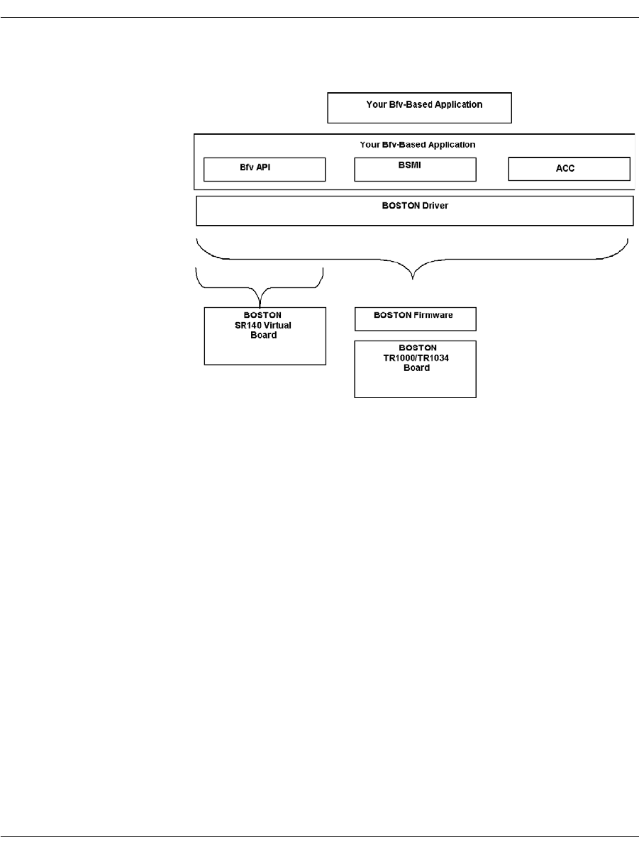
By using the Bfv API libraries, the application running on the host
processor can communicate through the Boston driver and firmware
to one or more Brooktrout boards.
Figure 1. Bfv Application Configuration
Fax boards have an exact module number of the TR1034 or TruFax®
board as indicated on the rotary switch on top of the board, so you
can have control over channels on individual boards in a multi-board
system. The Dialogic® Brooktrout® SR140 uses a module number of
0x41 for up to a maximum of 120 channels in a system.
The SR140 does the following:
Works on supported Windows® platforms running on Intel
processors.
Works with SIP and H.323 IP call control.
Operates with only one IP stack at a time.
Provides the same level of debugging and tracing that is
available on the TR1034 platform.
After configuration and licensing, the same application supports
the SR140 and your hardware based T.38 solution.
Because H.323 support occurs wholly within configuration, there
are additional configuration options for H.323 call control that
you can access using the Dialogic® Brooktrout® Configuration

Bfv API and Associated Libraries
November 2009 25
Tool. You can also configure H.323 support using the
configuration file. See the installation and configuration guide
that came with your software for more information about
configuring for H.323.
The TR1034 Boston modules are driven by the Bfv API. Call control
on Boston modules is driven by BSMI.
The Bfv API libraries are based on the BTLINE structure, which is a
logical abstraction of a physical channel. Each active channel stores
its information within its own BTLINE structure. You can access
and modify the BTLINE information through the Bfv API functions.
You can access other information kept in the Bfv API library, using
macros found in btlib.h.

The Bfv API Functions
November 2009 26
The Bfv API Functions
The Bfv API functions in all the Bfv API libraries are separated into
categories according to the tasks they perform. They are:
Configuration, Administration, and Management
Administration and Initialization
Firmware
Configuration
Debugging, Error Handling, and Return Values
Miscellaneous (for example, _dll_ and getopt)
Call Control
High Level Call Control
Low Level Call Control
Media Processing
Signal Generation and Detection
Voice Play and Record
Fax
File Format Manipulation
In addition to the functions, Dialogic supplies macros to provide
information or perform a specific task.

The Bfv API Functions
November 2009 27
Administration, Management, and Configuration
Administration and Initialization Functions and
Macros
The administration and initialization functions allow you to:
Attach and detach from a line or a session.
Configure the module instead of using a user-defined
configuration file such as btcall.cfg.
Interrupt a thread or process on an active line.
Reset the specified channel.
Get information about the module and channel address for the
specified channel.
Get the number of available channels.
You can also use specialized functions to:
Check for an address or facility.
Download and query the feature set.
Get information about and deactivate a board or SR140.
Receive a packet containing Boston addresses and commands
and perform internal Bfv API processing on all commands with
the packet (requires the Boston command set).
The line administration and initialization macros allow you to:
Get information about the current version of the Bfv API or
driver and some information about the operating system
environment.
Clear an item.
Get information about a line.

The Bfv API Functions
November 2009 28
The BTLINE Structure
When an application calls the BfvLineAttach (or
BfvSessionAttach) function to open and attach a specified channel,
the function creates a separate BTLINE structure for a channel and
returns a pointer to the line structure. All information about the
channel is stored in its BTLINE structure, but only the line state,
the line type, and channel number are actually relevant. The
BfvLineDetach (or BfvSessionDetach) function deallocates a
BTLINE structure.
Applications do not directly access the internal fields of the BTLINE
structure, but instead use functions, described in detail in the
Bfv API Reference Manual, and the following macros, described in
detail with other macros in the Bfv API Reference Manual:
LINE_HAS_CAP(lp, cap)
Confirms whether or not the line has the specified capability cap.
LINE_STATE(lp)
Returns or sets the line state of the specified line.
LINE_TYPE(lp)
Returns the line type of the specified line.
LINE_UNIT_NUM(lp)
Returns the channel number of the specified line.
A line is always in one of the following states:
LINE_STATE_AWAIT_TRAINING
LINE_STATE_CONNECTED
LINE_STATE_FAX_MODE
LINE_STATE_HOLDUP
LINE_STATE_IDLE
LINE_STATE_NOLOOP
LINE_STATE_OFF_HOOK
LINE_STATE_RCV_INFO
LINE_STATE_RESETTING
LINE_STATE_RETAIN
LINE_STATE_RINGING
LINE_STATE_TURNAROUND

The Bfv API Functions
November 2009 29
Hereafter each of the line states is referred to by the descriptive part
of its name only (for example, LINE_STATE_IDLE is referred to as
IDLE).
The current state of the line is stored in the BTLINE structure. A
pointer to this structure is passed as an argument to nearly all Bfv
API entry points and is provided to the application by the
BfvLineAttach function.
A number of functions and interrupts serve as inputs to the BTLINE
structure and affect the transition to different line states. Other
functions check the current line state.
Some functions conditionally branch to other points in the code, and
some prevent inappropriate action from occurring, for example,
frequent checking for CONNECTED before attempting to transmit
data.
The following is a partial list of the functions and interrupts and the
line state they set:
FUNCTION LINE STATE
BfvLineAnswer Sets the state to CONNECTED.
BfvLineAttach Initializes the state to IDLE.
BfvLineOriginateCall Sets the state to CONNECTED or OFF_HOOK
depending on the results from call
progress monitoring.
BfvLineReset Resets the state to IDLE.
BfvLineTerminateCall Sets the state to IDLE.
INTERRUPTS LINE STATE
Answer tone detect Sets the state to CONNECTED.
Direction change Sets the state to TURNAROUND.
Disconnect Sets the state to IDLE.
Received FSK data Sets the state to AWAIT_TRAINING.
Ring detect Sets the state to RINGING.
Training Sets the state to FAX_MODE.

The Bfv API Functions
November 2009 30
Channel Numbering
The Bfv API uses two numbering schemes when referencing
channels within a system. One is the unit number or ordinal channel
number; the other is the logical channel number.
The unit number is a number range 0…n-1, where n is the number of
channels in the system. The BfvLineAttach function uses the unit
number in its argument and returns a pointer to the BTLINE
structure, providing a means to reference the channel in future
function calls. For example, a system comprising two 60-channel
modules would have a unit number range of 0-119. The module that
had the firmware downloaded first would contain the channels
starting from 0.
The logical channel number is used together with the module
number to reference a work channel (also called a hardware channel)
in a system. The BfvSessionAttach function uses the module and
logical channel numbers in its arguments. Logical channels not only
include work channels traditionally considered to be channels, but
also administrative channels. The work channel number range for
logical channels is 2…n+1, where n is the number of work channels
on this hardware module.
Each module has a unique module number. For example, the same
system comprising two 60-channel modules could have the following
configuration:
First module: Module 2, work channels 2-61
Second module: Module 3, work channels 2-61
Each virtual module has 120 channels (the maximum allowed in a
system).
The BfvSessionAttach function also returns a BTLINE structure;
other functions that accept a BTLINE structure as an argument can
use either that returned from BfvLineAttach or
BfvSessionAttach. When detaching, use the corresponding detach
functions BfvLineDetach or BfvSessionDetach.
Unit numbers and BfvLineAttach are typical of our legacy product.

The Bfv API Functions
November 2009 31
Firmware Functions and Macros
With the specialized firmware functions, you can:
Download firmware to the module from a file or a buffer
Get information about a module’s firmware configuration options
With the firmware macros, you can determine:
Version number, build number, and date of the control processor
firmware
Version number, build number, and date of the boot ROM
firmware
Version number, build number, date of each DSP firmware, and
the number of DSPs on the module
Configuration Functions
The Bfv API provides functions that allow you to get the current
information about the telephony configuration, reset the telephony
state, and save telephony parameters to Non-Volatile RAM
(NVRAM).
You can also establish a connection between source and destination
telephony resources; get information about the connections, their
ports and classes; and clear all switching connections for a module.

The Bfv API Functions
November 2009 32
Configuration Files
The Bfv API uses several configuration files that let you configure
the Bfv API and driver, call control, and country-specific parameters.
These files are described below. Sample versions of the files are
stored in the directory brooktrout/boston/config.
The user-defined configuration file
A file that contains configuration parameters for the Bfv API and
driver. A sample of this file, called btcall.cfg, is provided with the
software, but you can write your own or modify/rename the
existing one. Many of the sample applications (see Sample
Applications and Utilities on page 127) use btcall.cfg.
The call control configuration file
A user-supplied file that contains call control configuration
parameters. Several samples of this file are provided with the
software. One sample is called callctrl.cfg, while others have
names that specify the type of telephony interface. See the
directory brooktrout/boston/config/samples.cfg for the names of
the files.
The telephony configuration file
This file is obsolete and has been superseded by the call control
configuration file.
The BT_CPARM.CFG file.
A read-only file that contains country-specific parameters.

The Bfv API Functions
November 2009 33
Module Status and Monitoring Functions
With the module status and monitoring functions, you can:
Set and get the state of the module by reading the status LED.
Set the module temperature threshold.
Get the temperature of the module.
Have the module perform a series of self tests and, optionally
report the results.
Have the module notify the application of events or conditions on
the module such as a network alarm, network error,
H.100/H.110 clock event, temperature alarm, RTP/RTCP
transport layer events, and the general status of the module.
Debugging, Error Handling, and Return Values
Functions
Several Bfv API functions help you debug your application program
and discover/recover from errors.
You can enable debug mode so that the Bfv API prints commands,
data, interrupts, and status messages, or you can set up a function to
be used with Bfv API debug mode that directs output to a file or
filter (see Debugging on page 91).
When you install the Bfv API, you enable recording of the history of
the activity of the driver along with the hardware type, the firmware
version, and the boot ROM version. You can then use functions to
dump the buffer containing the driver’s history for a module and
channel to a file. You can also clear the history buffer for a module
and channel so that it contains information relevant to the current
application.
If you have a RES structure that contains returned error
information from a previous Bfv API call, you can use the
BfvErrorMessage function to create a short and a long error message
in a BTERR structure. Then, you can print either the long or short
message from the structure.
When you start call control using BfvCallCtrlInit, you can enable a
call control log file.

The Bfv API Functions
November 2009 34
Structures and Return Values
The Bfv API uses argument structures to pass values to and from
functions. The application declares the argument structure and
passes a pointer to it to the function. The argument structure type is
named args_...; for example, struct args_speech. The same
argument structure type is used for functions that are related or in
the same category.
Contained within the argument structure are structure fields that
are used for input and/or output. Each function that uses an
argument structure has marked the fields that are used for each
purpose. Not all fields are used by all functions taking any particular
argument structure type.
Result structures are the most commonly used structures to return
information to the function. They are:
RES Returns status information in res.status and some additional
information in res.line_status.
CALL_RES Returns information about a call such as its type and destination. If
applicable, ISDN information such as called party and redirect
information are returned as well.

The Bfv API Functions
November 2009 35
Miscellaneous Functions and Macros
Some administration functions and macros cannot be classified with
other functions, but are useful in various ways. For example:
_dll... functions for use on Windows® operating systems. These
functions call standard C library functions such as fopen, fclose,
fread, and fwrite; their arguments use the runtime library linked
with the DLL.
The getopt function parses command line options in a UNIX
environment. Most of the sample applications/utilities use this
function (see Sample Applications and Utilities on page 127).
The BfvMemAllocFuncSet function allows you to write your
own functions to dynamically allocate and free memory instead
of using the Bfv API functions to do so.
The sleep macro lets you write applications that sleep for a
defined period of time (in seconds). This macro is only defined for
environments that do not have built-in sleep functions.

The Bfv API Functions
November 2009 36
Call Control
Call control functions enable the application to set up, initiate,
connect, disconnect, and perform other tasks related to the telephone
network. Three forms of call control are available: Bfv high-level and
low-level and BSMI-level.
Bfv Call Control
High-level Bfv call control functions simplify the process of accessing
the telephone system. Some of the high-level functions call the
low-level Bfv call control functions to automatically perform the
low-level tasks. However, the high-level functions trade flexibility
and control for ease of programming.
With the Bfv low-level call control functions, you can perform T1
robbed bit, T1/E1 PRI, or QSIG, analog, and BRI call control
functionality. See Volume 2 of the Bfv API Reference Manual for the
descriptions of the Bfv call control functions.
BSMI-Level Call Control
The BSMI-level call control functions are used to facilitate
communications directly between the Brooktrout module and the
telephony lines. These are the Bfv API Boston Simple Message
Interface (BSMI) functions that use messages to communicate
between the module and the telephone lines. The collection of
messages is the interface to the telephony component of the Boston
firmware and provides all the facilities for management, call control,
and performance statistics monitoring. Control message naming
conventions in the BSMI are descriptive of the functions they serve
and make it easier to develop applications. When developing an
application, you do not need to have a detailed knowledge of the
protocol involved, although a general understanding of call models is
beneficial. You can use one of many different signaling protocols
such as T1/E1 PRI; R2; and Local Exchange Carriers (LEC) T1
Robbed Bit, Analog and BRI. See Robbed Bit Signaling on page 264 -
Using the BSMI R2 Signaling Capability on page 336 for more
information about the protocols.
Note: BSMI is not supported on QSIG.

The Bfv API Functions
November 2009 37
Typically, the BSMI is used as one component of a system. Firmware
download, for example, is achieved using the call control functions of
the Bfv API. Through the Bfv API, you can perform all appropriate
configuration and management functions for the Boston series of
products.
BSMI is used by the Bfv call control functions to perform call
processing. BSMI is a level lower than the Bfv API, providing
greater flexibility.
The host communicates with the Brooktrout module through the
Control Interface. The host application (referenced as L4) issues
BSMI control messages to configure the module or to instruct it to
perform a specific action, such as make a call, clear a call, or request
the status of an interface. The module-issued BSMI control messages
(referenced as L3) inform the host of the status of the interface, call
events, or an error condition.
BSMI supports the R2 signaling protocol. Using the BSMI host to
module messages, you can:
Start and stop the R2 protocol on a particular timeslot on an E1
span.
Block or unblock an idle B-channel (the ISDN channel that
handles data).
Place an outbound call.
Answer an inbound call.
Disconnect a call.
Reject an incoming call.
BSMI module to host messages respond to the host by:
Starting and stopping the R2 protocol.
Blocking or unblocking the B-channel.
Seizing the line for an incoming call.
Alerting the host and then connecting a call.
Clearing a request.
Notifying the host when the remote end phone is ringing.
Notifying the host when the call is disconnected at the remote
end.
Providing a protocol error or invalid command status message.

The Bfv API Functions
November 2009 38
Media Processing
Media processing refers to the application that is performed on the
Brooktrout modules. Depending on the product configuration, it can
include:
Signal generation and detection
Voice play and record
Faxing
File format manipulation
Signal Generation and Tone Detection
With the signal generation and tone detection functions, you can:
Play call progress signals and generate other tone groups and
tone patterns.
Get the next call progress code.
Enable and disable DTMF detection.
Discard tones from a buffer.
Wait for a tone and return it as an ASCII character or return it
without disturbing the buffer.
Play a tone for a specified time.
Play a single frequency tone or a custom tone.
Replace a tone in the buffer for reuse.
Brooktrout module receive call progress signals generated by telcos
and Private Branch Exchanges (PBXs) before, during, and after
dialing. The module’s call progress analysis process then interprets
them.
During call progress analysis, modules can report dial tone
detection, ring-back, busy signals, remote fax tone detection, and
other important information. Applications can use this information
to determine their next course of action, to display the status of a
call, or to track billing information. Applications can use postdialing
results, such as HUMAN and BUSY, to decide what redialing strategy
to use.
Brooktrout modules can also generate and play DTMF and MF tone
groups and single tone patterns to send to the telco or PBX.

The Bfv API Functions
November 2009 39
Voice Record and Play
With the Bfv voice record and play functions, the application can:
Open, play, and close a previously recorded prompt file.
Record speech into an infopkt stream, a raw speech data buffer,
a raw speech file, or a wave file.
Play back speech from an infopkt stream, a raw speech data
buffer, a raw speech file, or a wave file.
Modify the volume and rate of a speech playback while it is in
progress.
The voice functions allow you to write Interactive Voice Recognition
systems where you can record prompts for later playback. You can
also build voice mail systems for recording and playing back
messages.

The Bfv API Functions
November 2009 40
Fax Functions
The Bfv API provides a wealth of fax functions that allow you to
control every aspect of sending and receiving V.17 or V.34 faxes.
The fax functions are divided into high-, mid-, and low-level
functions. Volume 4, Fax Processing, Bfv API Reference Manual
provides a detailed description of each Bfv function.
Generally, the high-level functions simplify the process of
transmitting and receiving facsimiles. Since the high-level functions
incorporate many of the appropriate low-level functions to
automatically perform the basic low-level tasks, applications using
the high-level functions are freed to perform other tasks. For
example, the high-level function BfvFaxSend is constructed of
these mid- and low-level functions:
BfvFaxBeginSend
BfvFaxEndOfDocument
BfvFaxGetRemoteInfo
BfvFaxSendPage
BfvFaxSetLocalId
BfvFaxWaitForTraining
The high-level functions trade the maximum flexibility and control
provided by the low-level functions for ease of programming.
The mid-level functions provide more flexibility and control than the
corresponding high-level functions, but they require more knowledge
of and attention to the basic steps involved in sending and receiving
facsimiles.
The low-level functions provide the greatest flexibility and control
over sending and receiving facsimiles, but they require extensive
knowledge of and attention to the basic steps involved in each of
these tasks. For example, applications can screen phone calls based
on an ID string or NSF information with the low-level functions, but
not with the high-level functions.
Both the high- and mid-level functions use only infopkt files, so the
distinction between them is measured in the flexibility and control
they provide. The low-level functions, however, use only raw data
files.

The Bfv API Functions
November 2009 41
Combining the high-, mid-, and low-level functions within the same
application program is valid and useful. Need for the low-level calls
depends on the degree of flexibility and functionality an application
requires.
Table 1 contains a partial list of the high-, mid-, and low-level
functions that perform fax tasks.
Table 1. Fax Functions by Type
Type/Level Function Names
High-Level BfvFaxPoll
BfvFaxReceive
BfvFaxSend
Mid-Level BfvFaxBegin
BfvFaxBeginReceive
BfvFaxBeginSend
BfvFaxEndReception
BfvFaxNextPage
BfvFaxReceivePage
BfvFaxReceivePages
BfvFaxSendPage
BfvFaxSetReceiveFmt
BfvFaxTurnaround
Low-Level BfvFaxBeginRaw
BfvFaxBeginSendRaw
BfvFaxEndOfDocument
BfvFaxGetLocalId
BfvFaxGetRemoteInfo
BfvFaxNextPageRaw
BfvFaxPageParams
BfvFaxReceiveData
BfvFaxReceiveFile
BfvFaxSendData
BfvFaxSendFile
BfvFaxStripParams
BfvFaxWaitForTraining

The Bfv API Functions
November 2009 42
In addition, the fax functions are divided into two subgroups: those
that process infopkt-formatted data files and those that process
ASCII or G3 data files in other formats. For fax functions that
process raw ASCII or G3 data files rather than infopkt-formatted
data files, see Volume 4, Fax Processing, Bfv API Reference Manual.
File Format Manipulation Functions
Using the file format function calls, you can perform the following
infopkt operations:
Open and close infopkt stream files
Find the pointer position in an infopkt stream file
Look for an offset to a specific place in an infopkt file
Read from and write to an infopkt stream file or buffer
Put the last infopkt read back into the infopkt stream file
Create your own function to handle user-defined infopkt files
Infopkts
An infopkt is a structure, consisting of a tag and associated data,
that organizes different data types (ASCII, voice, and fax data) into a
single structure for transmission or reception.
The Bfv functions can process voice and fax data that is stored in
files containing infopkt structures. Infopkt structures contain speech
or fax formatting and control parameters, speech or fax data, or
pointers to other data or infopkt files. These structures provide a
flexible and easily extendable method to combine and transmit
various types of data.

The Bfv API Functions
November 2009 43
For voice applications, infopkts provide an easy means to build
sophisticated interactive voice systems. Using infopkts, a voice
application can create a master prompt file that builds all of the
system's prompts out of short phrases.
This scheme:
Reduces the amount of disk space needed for storage.
Enables the application to build new prompts as changing
demands on the system dictate.
Simplifies the development of multilingual systems that can
translate recorded prompts to other languages on-the-fly.
For fax applications, infopkts provide a flexible means to transmit a
complex, computer-generated fax document.
A fax transmission consists of one or more documents. A document
consists of one or more pages containing the document parameters,
agreed upon by two communicating fax machines according to the
T.30 protocol, that do not change. A page consists of one or more
strips of data, converted from their original format to the established
document format for transmission.
To a fax machine, a document is a simple object with three
parameters: vertical resolution, length, and width. To a computer, a
document is often more complex.
For example, fax applications might require the transmission of
ASCII data in fax format. The fax module converts the ASCII data to
G3 format in real-time. A file header and signature, already in
G3 fax format, can accompany the ASCII data. The infopkt structure
makes it easy to send a document of this type because it organizes
fax and ASCII data into a single structure for transmission and
reception.
The Bfv API defines and supports the infopkt types described on the
following pages:
Tag Infopkts
Data Infopkts
Indirect Infopkts
User-Defined Infopkts

The Bfv API Functions
November 2009 44
Tag Infopkts Contain speech parameter structures (which describe the sample
rate, coding format, and data format of the speech or indicate the
end of speech playback), and fax parameter structures (which
describe a strip or page of data, the line parameters, or control
parameters). They are:
INFOPKT_ASCII_STRIP_PARAMETERS
Tag containing parameters for ASCII data strip.
INFOPKT_BEGINNING_OF_PAGE
Tag indicating the beginning of a new page with no new parameters
from the previous page.
INFOPKT_DOCUMENT_PARAMETERS
Tag indicating new page composition parameters. An infopkt stream
must begin with this infopkt type. This is used, for example, to
change the resolution between pages in the middle of a fax
transmission.
INFOPKT_EFF_PAGE_PARAMETERS
Tag containing enhanced fax format page parameters.
INFOPKT_END_OF_SPEECH
Tag indicating end of speech playback.
INFOPKT_FAX_HEADER
Tag specifying a header or footer to appear on all subsequent pages
of a fax transmission.
INFOPKT_G3_STRIP_PARAMETERS
Tag containing parameters for G3 data strip.
INFOPKT_PAGE_PARAMETERS
Tag containing margin and padding parameters for a page.
INFOPKT_SPACE
Tag containing the spacing parameters for a fax page or a fax
overlay.
INFOPKT_SPEECH_PARAMETERS
Tag containing parameters for succeeding speech infopkts.
INFOPKT_T30_PARAMETERS
Tag containing T.30 line parameters bit rate and scan time. When
ECM is in use, the scan time specification has no effect.

The Bfv API Functions
November 2009 45
Data Infopkts Contain just the header and data, permitting applications to
organize large files as a sequence of small data infopkts. They are:
INFOPKT_ASCII
ASCII data.
INFOPKT_G3
G3 data.
INFOPKT_PROMPT_MAP
Used only in prompt files. Contains information on how to find each
of the phrases in the prompt file.
INFOPKT_SPEECH
Speech data in any of several coding formats.
Indirect Infopkts Contain a pointer to a file that contains either raw data (ASCII,
speech, or G3) or infopkts. They are:
INFOPKT_INDIR_ASCII
Pointer to an ASCII file.
INFOPKT_INDIR_DCX
Pointer to an Intel DCX fax file that contains PCX data and its own
header information.
INFOPKT_INDIR_G3
Filename of a G3 file.
INFOPKT_INDIR_INFOPKT
Pointer to another infopkt stream file.
INFOPKT_INDIR_SPEECH
Pointer to a raw speech file.
INFOPKT_INDIR_TIFF
Pointer to a TIFF-F file that contains G3 data and its own header
information.
INFOPKT_INDIR_WAVE
Pointer to a wave file that contains speech data and its own header
information.

The Bfv API Functions
November 2009 46
User-Defined Infopkts Contain a header (the document’s title, the subject of the document,
or the total number of pages that the document contains) and
user-defined information (document summary and statistics, etc.)
useful to an application. When the Bfv API encounters these infopkt
types, it ignores them. See the BfvInfopktUser function in Volume
4, Fax Processing, Bfv API Reference Manual. They are:
INFOPKT_USER0_USER1...._USER9
Infopkt containing a header and storage for user application
information. A maximum of ten user-defined infopkt types
(numbered 0 to 9) are included in an infopkt stream.
INFOPKT_ANNOTATION
Contains header and ASCII text, but is otherwise identical to the
user types described above.

The Bfv API Functions
November 2009 47
The Infopkt Stream
An infopkt stream is a file or memory buffer containing concatenated
individual infopkts. The length of an infopkt stream is limited only
by the file size conventions specific to an operating system. The
BfvInfopktOpen function opens file-based infopkt streams, and the
BfvInfopktOpenMem function opens memory-based infopkt
streams.
For speech record and play applications, the first infopkt in the
infopkt stream depends on the type of speech file.
If the speech file is an indexed prompt file (see mkprompt on
page 155 in this manual, and the BfvPromptPlay function in
Volume 3 of the Bfv API Reference Manual), an
INFOPKT_PROMPT_MAP infopkt begins the infopkt stream. An
INFOPKT_SPEECH_PARAMETERS infopkt begins each new speech file
embedded within the infopkt stream.
If the speech file is a simple speech file, one recorded with the
BfvSpeechRecord function, an INFOPKT_SPEECH_PARAMETERS
infopkt begins the infopkt stream.
Creating an Infopkt Stream
The mkinfopk program, included on the distribution media, builds
an infopkt stream. It has the following command syntax:
mkinfopk -o output_fname {infopkt_type arg}...
For more detailed information on mkinfopk, see mkinfopk on
page 153 in this manual.
The decode program, also included on the distribution media, reads a
specified infopkt stream and lists the individual infopkts within the
stream. See Sample Applications and Utilities on page 127 in this
volume for more detailed information on how to use this utility.
Figure 2 illustrates how to create an infopkt stream to play either an
indexed prompt file or a simple speech file. You must create a
separate infopkt stream for each type.
-o output_fname Is the name of the output file.
infopkt_type Indicates the type of infopkt which follows.
arg Is the argument for the infopkt. Depending on
the infopkt_type, it is either a filename or a
dummy value.

The Bfv API Functions
November 2009 48
Figure 2. Flow Chart for Creating Infopkt Streams that Play
Speech
_PROMPT_MAP
Index to prompt file
Indexed Prompt File
(mkprompt)
_SPCH_PARAMS
smp rate, coding fmt, bits-
smp, afe rate, data fmt
_SPEECH
Speech Data
CVSD, ADPCM, PCM, OKI
_SPEECH
Speech Data
CVSD, ADPCM, PCM, OKI
_END_OF_SPEECH
_SPCH_PARAMS
smp rate, coding fmt, bits-
smp, afe rate, data fmt
_SPEECH
Speech Data
CVSD, ADPCM, PCM, OKI
_SPEECH
Speech Data
CVSD, ADPCM, PCM, OKI
_END_OF_SPEECH
embedded speech fileembedded speech file
_SPCH_PARAMS
smp rate, coding fmt, bits-
smp, afe rate, data fmt
Simple Speech File
(mkinfopk)
_SPEECH
Speech Data
CVSD, ADPCM, PCM, OKI
_SPEECH
Speech Data
CVSD, ADPCM, PCM, OKI
_SPEECH
Speech Data
CVSD, ADPCM, PCM, OKI
_SPEECH
Speech Data
CVSD, ADPCM, PCM, OKI

The Bfv API Functions
November 2009 49
To create an infopkt stream file to test the fax functionality of your
hardware and software:
mkinfopk -o fax.ips doc 1 ascii fax.c
Where:
For fax-receiving applications, an
INFOPKT_DOCUMENT_PARAMETERS
infopkt begins each new G3 page within it. If the application uses a
nonstandard receive format (see the BfvFaxSetReceiveFmt
function in Volume 4, Fax Processing, Bfv API Reference Manual), it
must also include a G3_STRIP_PARAMTERS infopkt.
For fax-transmitting applications, an infopkt stream must begin
with an INFOPKT_DOCUMENT_PARAMETERS infopkt. Any type of
infopkt or combination of infopkts can follow the first
INFOPKT_DOCUMENT_PARAMETERS infopkt.
Within a fax-transmitting application, a new page is indicated when
one of the following infopkt types is encountered in an infopkt
stream:
INFOPKT_BEGINNING_OF_PAGE
INFOPKT_DOCUMENT_PARAMETERS
INFOPKT_T30_PARAMETERS
INF0PKT_FAX_HDR
Figure 3 on page 50 illustrates how to create an infopkt stream that
transmits G3 data. G3 data includes MH, MR, MMR, and PCX
formats.
fax.ips Is the name of the output infopkt stream file that contains
the ASCII file fax.c (the sample fax application program
included on your distribution CD).
doc Is required as the first infopkt in a stream (1 is its
argument). See mkinfopk on page 153 for more
information about doc.
ascii Indicates that the input file fax.c is an ASCII formatted
file.
fax.c Is the input file.
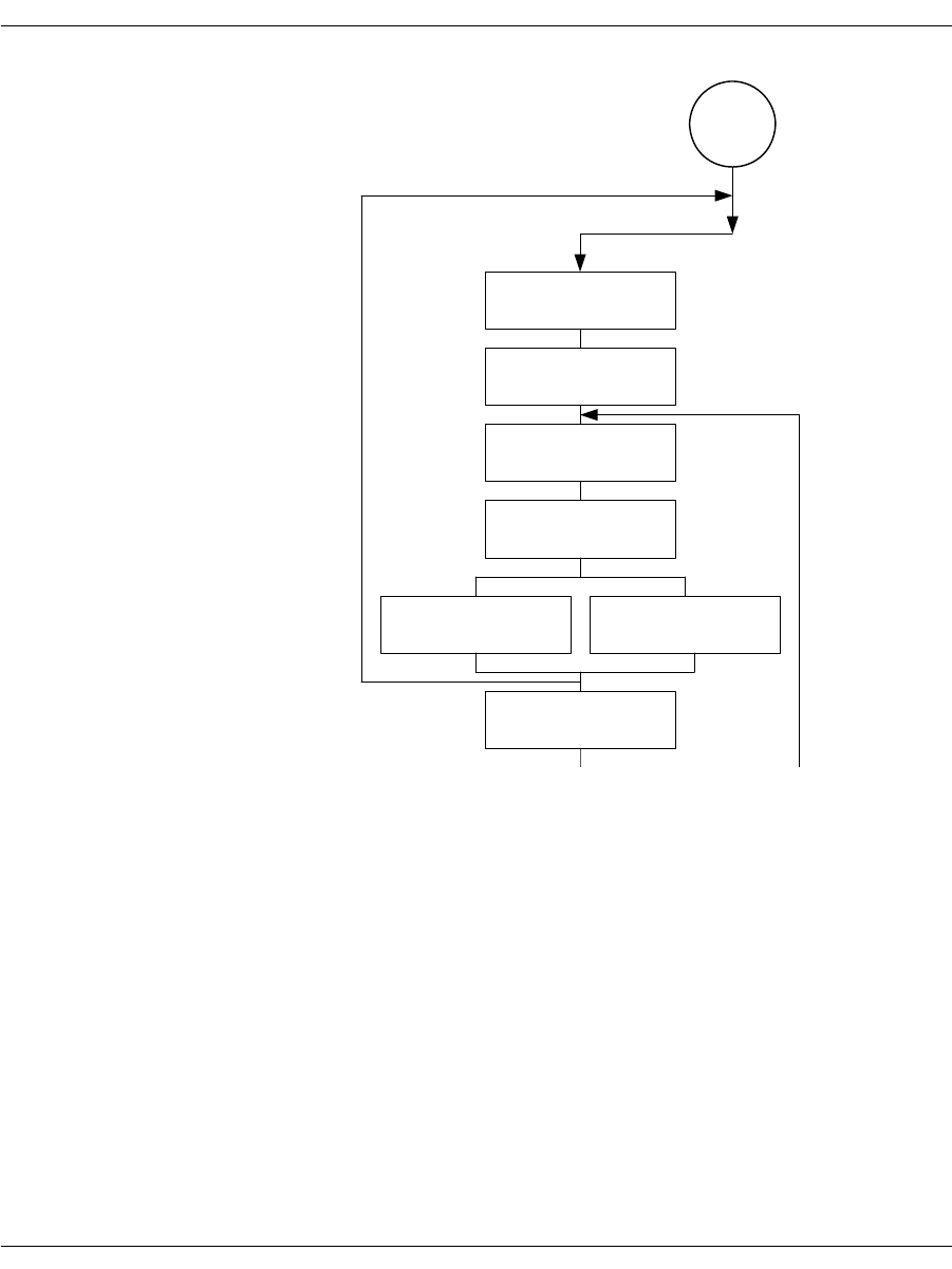
The Bfv API Functions
November 2009 50
Figure 3. Creating Infopkt Streams that Transmit Facsimiles
_DOC_PARAMS
res, len., width
optional/conditional
START
_T.30_PARAMS
bit rate, scan time
_PAGE_PARAMS
_STRIP_PARAMS
G3, ASCII
DATA
G3, ASCII
INDIR_DATA
G3, ASCII, DCX, TIFF
_B_O_P
*
*
*
*

The Bfv API Functions
November 2009 51
Infopkt Structure
Every infopkt consists of a header and data. The 4-byte header
consists of a type code and a length. The type code defines the
infopkt type, and the length field indicates the total length of the
infopkt, including the header. Data consists of raw data, formatting
parameters or, in the case of indirect infopkts, pointers to other files.
The maximum length of an individual infopkt is 30,000 bytes, but
Dialogic recommends limiting the size to approximately 1K. This
limit affects the size of infopkts only and has no effect on the size of a
fax document, since large fax documents are simply converted to
multiple infopkts within an infopkt stream.
When indirect infopkts point to other infopkt stream files, the
maximum nesting depth is three. All file names that occur in
indirect infopkts must be 0-terminated.
The infopkt.h file, located in the inc subdirectory, contains the
definitions of the infopkt structures.
See Appendix E in Volume 6 of the Bfv API Reference Manual for the
parameter values and defaults of each tag type infopkt.
Speech Infopkt Parameters
The INFOPKT_SPEECH_PARAMETERS infopkt defines the speech
parameters for infopkt-formatted speech files. These parameters
include the coding format, the compressed sample rate, the number
of bits per sample, the analog front end (afe) rate, and the data
format. In infopkt streams made up of simple speech files, this
infopkt begins the infopkt stream. In infopkt streams made up of
indexed prompt files, it begins each new speech file embedded in the
stream.
Applications use the BfvSpeechRecord function to record speech
in infopkt format (see the Bfv API Reference Manual, Volume 3 for a
complete description). Valid settings for the data coding format,
compressed sample rate for playback, and number of bits per sample
are found with the BfvSpeechRecord function.

The Bfv API Functions
November 2009 52
Fax Infopkt Parameters
The T.30 protocol requires two communicating fax machines to agree
on several transmission parameters at the beginning of a facsimile
transmission. These transmission parameters include the bit rate,
scan time, coding scheme, and the basic document format
parameters – vertical resolution, page width, and page length. The
least capable fax machine determines the values of these
parameters; both fax machines adjust to the final values.
Two infopkts:
INFOPKT_T30_PARAMETERS
INFOPKT_DOCUMENT_PARAMETERS
affect the parameters that are negotiated during the T.30 protocol
handshaking procedure.
The INFOPKT_T30_PARAMETERS infopkt specifies the desired values
of the transmission parameters. Normally the default values are
used, but INFOPKT_T30_PARAMETERS is useful, for example, for
setting a lower bit rate.
The INFOPKT_DOCUMENT_PARAMETERS infopkt sets the document
related parameters: vertical resolution, length, and width (only the
vertical resolution is programmable). These parameters format the
fax data that is sent out on the phone line.
INFOPKT_DOCUMENT_PARAMETERS is required and specifies the
desired resolution. If it appears in the midst of an infopkt stream,
both machines might renegotiate to the new parameter values.
While document parameters define an entire fax document sent over
the telephone line, page parameters define an entire page only, and
strip parameters define horizontal strips of data within a page.
For ASCII data, there are page parameters and strip parameters.
For G3 data, there are strip parameters. Because page formatting
elements (top and bottom margins, etc.) are inherent in G3 data;
there are no separate page parameters.
The INFOPKT_PAGE_PARAMETERS infopkt defines the ASCII page
parameters, which apply only to pages. Its use is optional, and when
it is not included with ASCII data infopkts, the module uses the
default values (see Appendix E in Volume 6 of the Bfv API Reference
Manual for default values).

The Bfv API Functions
November 2009 53
The strip parameters infopkts:
INFOPKT_ASCII_STRIP_PARAMETERS
INFOPKT_G3_STRIP_PARAMETERS
define the actual strips of data that make up a page and must
precede an ASCII or G3 data type infopkt only to change the default
or previously applied strip parameter values (see Volume 6,
Appendix E in the Bfv API Reference Manual for default values).
Dialogic, however, recommends that you include a strip parameter
infopkt whenever you define a strip, even if the default values are
appropriate for the strip. Strip parameters include the basic format
of the data (that is, ASCII or G3 data) and presentation parameters
such as vertical resolution, width, and, in the case of ASCII, left and
right margins.
Strip parameters ensure that the strip data is sent out properly and
the received fax is displayed with the proper proportions. The
module converts strip data to the proper vertical resolution before
transmitting it.
For example, if the T.30 document resolution is set to fine resolution,
and a G3 strip is in normal resolution, the firmware converts the
data to fine resolution, replicating each line. Likewise, if the T.30
document resolution is set to normal resolution, and a G3 strip is in
fine resolution, the firmware converts the data to normal resolution,
removing every other line. If the T.30 document resolution and a
G3 strip resolution are the same, the module transmits the data
as-is. The vertical resolution of the strip data informs the module
when to convert data and how to convert it.
When ASCII strip data is sent to the module, the current vertical
resolution parameter is set to normal, even if an
INFOPKT_ASCII_STRIP_PARAMETERS infopkt is inserted into the
infopkt stream. Thus the resolution of any G3 strip data,
encountered later in the infopkt stream, is also assumed to be
normal, unless otherwise specified by an accompanying
INFOPKT_G3_STRIP_PARAMETERS infopkt.
When two consecutive G3 strips of data are sent to the module, an
INFOPKT_G3_STRIP_PARAMETERS infopkt must be inserted
between them. Since each G3 strip data ends with an RTC marker
(six consecutive end-of-line codes) that is interpreted by the module
as the end of the strip of data, an INFOPKT_G3_STRIP_PARAMETERS
infopkt is required to indicate the beginning of the second G3 strip.
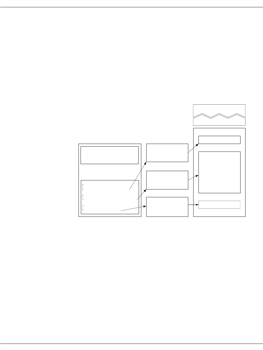
The Bfv API Functions
November 2009 54
When a single G3 strip consists of multiple G3 infopkts, do not insert
an INFOPKT_G3_STRIP_PARAMETERS infopkt between the
G3 infopkts.
Figure 4 illustrates how an electronic mail document (ASCII),
accompanied by a cover sheet, a letterhead, and a signature, could be
delivered to a fax machine.
Figure 4. Conversion of a Partial Infopkt Stream to a Fax
Document
Part of the infopkt stream, a file containing a series of infopkts that
contains this fax example, is shown below:
INFOPKT_DOCUMENT_PARAMETERS
(Tag containing new page composition parameters; a fax infopkt
stream must begin with this infopkt type)
INFOPKT_G3_STRIP_PARAMETERS
(Parameter Structure)
lettrhed.g3
lettrbod.asc
sign.g3
The TRxxx series
of fax/voice boards
are now available...
Dialogic Corp
President
BOP (Beginning of page)
letterhead
Fax Document,
Page 1
G3_Strip_Parameters
Indir_G3(lettrhed.g3)
Ascii_Strip_Parameters
Indir_Ascii(Lettrbod.asc)
G3_Strip_Parameters
Indir_G3(sign.g3)
Doc_Parameters
G3_Strip_Parameters
G3 (data; cover sheet)
cover sheet
letter body
signature
Fax Document,
Page 2
Infopkt Stream

The Bfv API Functions
November 2009 55
This two-page document contains a G3 fax document as a cover page.
INFOPKT_G3
(Cover sheet; G3 data)
It is followed by a page boundary tag,
INFOPKT_BEGINNING_OF_PAGE. The data for the cover sheet is
stored in the infopkt stream.
INFOPKT_BEGINNING_OF_PAGE
(Cover sheet is on its own page)
INFOPKT_G3_STRIP_PARAMETERS
(Parameter Structure)
The second page starts with a G3 document containing the
letterhead. It is stored in a separate file.
INFOPKT_INDIR_G3
(Document letterhead; G3 filename)
INFOPKT_ASCII_STRIP_PARAMETERS
(Parameter Structure)
The next strip of the second page is ASCII data which is also stored
in a separate file.
INFOPKT_INDIR_ASCII
(Contents of E-Mail message; ASCII filename)
INFOPKT_G3_STRIP_PARAMETERS
(Parameter Structure)
The second page ends with G3 data, contains the signature, and is
also stored in a separate file.
INFOPKT_INDIR_G3
(Signature data is in infopkt structure; G3 data)
The bulk of most infopkt files are types INFOPKT_G3 and
INFOPKT_ASCII. Two files containing infopkts are concatenated.


Developing a Voice Application
November 2009 57
Developing a Voice Application
Recording and Playing Voice
The following steps for recording and playing back speech are
demonstrated:
How to record voice
How to play back previously recorded voice
These steps are the same for all supported operating systems.
To record and then play speech back, first select the voice channel on
which you want to record your message. Then, use the voice.c sample
program, included on your distribution CD, to record and play back
speech.

Developing a Voice Application
November 2009 58
Recording Voice
1. Prepare channel 2 to record your message:
voice -u 2 -r voice.ips
The command voice invokes the voice.c program, whose
arguments include:
The -u 2 argument selects channel 2 as the recording channel;
and the -r argument places channel 2 in record mode. Voice.ips
is the speech infopkt stream file in which to store the voice
message. The channel waits for a ring signal.
Arguments
-c num Call the given number, else wait for ring.
-f Specify record coding format; use the number of
the format or one of the following names:
adpcm
adpcm32
adpcm24
pcm_ulaw
pcm_ulaw64
pcm_ulaw48
pcm_ulaw88
pcm_alaw
pcm_alaw64
pcm_alaw48
pcm_alaw88
g723-1
g723-1-53
g723-1-63
g729-a
sx7300
sx9600
gsm_610
gsm_660
1
2
3
7
8
9
10
14
15
-l Loop forever, sending or receiving.
-n secs Specify recording time in seconds.
-p Play.
-r Record (default 10 seconds).
-u unitnum Use specified channel.

Using Prompt Files
November 2009 59
2. Dial the phone number of the channel you selected. Make sure the
phone line is attached to the selected channel.
The voice.c program does not indicate when to begin recording.
Begin recording when the line goes off-hook (when you no longer
hear ringing).
Playing Back the Voice Message
¾
Request that a channel (0 in the example) play back your
previously recorded message stored in voice.ips.
1. At the system prompt, type:
voice -u 0 -p voice.ips
2. Dial the phone number of the channel. You should hear your
recorded message.
Using Prompt Files
Prompt files are infopkt files that contain many individual speech
phrases in a single file. Each phrase is a partial or complete prompt
in infopkt format followed by an INFOPKT_END_OF_SPEECH infopkt
with mode value 1. The prompt file starts with an
INFOPKT_PROMPT_MAP infopkt, which contains file offsets to each
individual phrase.
The Bfv API contains functions that open and close a Brooktrout
prompt file and play individual phrases stored in it. For example,
after an application opens a Brooktrout prompt file, it can call the
BfvPromptPlay function to play any individual phrase, or it can
call the BfvPromptPlay function multiple times to concatenate
phrases and create a complete prompt.
Using Brooktrout prompt files provides two advantages. Since all of
the prompts are stored in a single file, tracking and maintaining
prompts is easier. And because you can combine phrases to create
complete prompts, you can reduce the amount of disk space needed
for overall speech storage.

Using Prompt Files
November 2009 60
Using the mkprompt Utility
The mkprompt utility converts multiple infopkt files into a
Brooktrout prompt file and updates an existing Brooktrout prompt
file by adding new phrases or modifying existing phrases.
When you create a Brooktrout prompt file, the mkprompt utility
automatically assigns each infopkt file a phrase number,
sequentially, in the order that you enter each file name at the
command line. The mkprompt utility always assigns the phrase
number 0 to the first infopkt file you enter.
When you update a Brooktrout prompt file, you assign a phrase
number to each infopkt file you are adding to the existing Brooktrout
prompt file.
Since the mkprompt utility cannot return phrase numbers of
individual prompt files in a Brooktrout prompt file, be sure to keep
your own record. You might need this information when you update
your prompt file.
Both the mkprompt utility and the Bfv API permit you to include the
text of each phrase in the Brooktrout prompt file. Create an infopkt
file for each phrase in which the first infopkt in the file contains the
text annotation and the remaining infopkts contain the speech that
make up the phrase. The mkprompt utility treats the whole file as a
phrase infopkt, and the BfvPromptPlay function skips over the
annotated text.
Creating a New Prompt File
To create a new Brooktrout prompt file, at the command line type:
mkprompt prompt_file [phrase1.pkt phrase2.pkt...]
Where:
The mkprompt utility automatically assigns phrase 0 to the file you
enter as phrase1.pkt and sequentially numbers any additional files
in the order that you enter them.
prompt_file Specifies the name of the prompt file to create.
phrase1.pkt,
phrase2.pkt, ... Provides the names of the infopkt-formatted.
Prompts files in the order in which you enter
them at the command line.

Developing a Fax Application
November 2009 61
Updating an Existing Prompt File
To update an existing Brooktrout prompt file, at the command line
type:
mkprompt -u phrase_num prompt_file phrase.pkt:
Where:
The mkprompt utility opens the existing Brooktrout prompt file and
append the new phrase if the phrase number you specify is new or
replace the old phrase whose phrase number matches the phrase
number you specify.
Developing a Fax Application
Sending and Receiving a Fax
The following are the step-by-step instructions for transmitting and
receiving a fax:
How to create an infopkt stream using the mkinfopk utility.
How to send a fax (an infopkt stream file) from one channel to
another channel in your system.
How to send a fax from an external fax machine to one channel
in your system. This same fax is then transmitted back to the
same fax machine from the same channel in your system.
-u Specifies the update command.
phrase_num Provides the index number to assign the
infopkt-formatted input file.
prompt_file Provides the name of the prompt file.
phrase.pkt Provides the name of the infopkt-formatted prompt
file to add to the prompt file.

Developing a Fax Application
November 2009 62
Sending a Fax from One Channel to Another
¾
Use the fax sample program to send a fax from one channel to
another in your system.
1. Prepare channel 1 to receive a fax:
fax -u 1 -r recfile.ips
fax invokes the sample fax program with the following
arguments:
The channel is now set to receive a fax and is waiting for a ring
signal.
2. Send a fax from channel 0 to channel 1.
In a second window, type:
fax -u 0 -s wphonenum fax.ips
-u Specifies that the following number is the
number of the channel that receives a fax (in this
case channel 1 is used).
-r Places the channel (1) in receive mode.
recfile.ips Creates a file, recfile.ips, in which to receive a
fax.
-u Specifies that the following number is the
number of the channel that sends a fax (in this
case channel 0 is used).
-s Places the channel (0) in send mode.
wIn robbed-bit T1 TDM environments, checks
the signaling if w is the first character of the
string.
In E&M immediate mode, causes the channel
to wait and see if the T1 slot is free.
In E&M wink mode, causes the channel to
wait for a wink signal from the remote side.
Anywhere else in the string, waits for dial
tone.
phonenum Specifies the phone number of the channel to
receive the fax (in this case channel 1).
fax.ips Sends the infopkt stream file fax.ips previously
created with the mkinfopk utility.

Developing a Fax Application
November 2009 63
Sending a Fax to a Channel from an External Fax
Machine
Use the fax.c sample program to send a fax from an external fax
machine to a channel in your system. Then send the same fax back to
the same fax machine from the same channel in your system.
1. Prepare channel 1 to receive a fax as you did in the previous
example. Use the same input filename recfile.ips used to send a
fax from one channel to another in the same system:
fax -u 1 -r recfile.ips
Channel 1 is now set to receive a fax and is waiting for a ring
signal.
2. At the fax machine, insert the sample fax in the fax machine and
call the channel's (channel 1) phone number in the normal way.
At the tone send your sample fax.
Wait for the selected channel to receive the sample fax.
3. Send the received fax back to the fax machine:
fax -u 1 -s wphonenum recfile.ips
This time, phonenum is the phone number of the external fax
machine.
You can examine the structure of the infopkt stream recfile.ips
before you transmit it back to the fax machine.
decode recfile.ips

Developing a Fax Application
November 2009 64
Using Bfv API Fax Functions
The following sections show how to send and receive facsimiles using
the high- and low-level function calls, noninfopkt function calls, and
TIFF-F function calls. It also shows how to send and receive
facsimiles in MR and MMR format, access infopkt streams and
TIFF-F fax files from an application, combine data on a single page
using TIFF-F fax files, interpret fax status information from an
application, and how to use prompt files.
The following declarations are assumed to be in effect for all
examples.
struct args_line_admin args_admin;
struct args_telephone args_tel;
struct args_speech args_speech;
struct args_fax args_fax;
struct args_fax_t30_params args_t30;
struct args_fax_page_params args_page;
struct args_fax_strip_params args_strip;
struct args_tone args_tone;
struct args_download args_download;
struct args_dh args_dh;
struct args_intlimit args_intlimit;
struct args_infopkt args_infopkt;
struct args_tiff args_tiff;
Using High- and Low-Level Functions
The Bfv API library contains both high- and low-level function calls
(see Table 1 on page 41). Several low-level function calls are
combined into one high-level function to provide a quick and easy
method to send or receive a facsimile.
The low-level functions, on the other hand, provide more flexibility
and functionality than the higher level function calls.
Sending a Fax Using High-Level Function Calls A typical way to
send a fax using the high-level fax function calls is demonstrated
below. Each function is presented in sequential order, and the action
it performs is described beneath it.
BT_ZERO(args_admin);
args_admin.unit = unit;
lp = BfvLineAttach(&args_admin);
Attaches to a free channel and gets a line pointer.

Developing a Fax Application
November 2009 65
args_admin.config_file_name = "usrcnfig.cfg";
BfvLineReset(lp,&args_admin);
Resets the channel and sets the user-configured options selected in
the user-defined configuration file named, usrcnfig.cfg.
BT_ZERO(args_infopkt);
args_infopkt.fname = name;
args_infopkt.fmode = "r";
ips = BfvInfopktOpen(&args_infopkt);
Opens the infopkt-formatted file called name for reading and
transmission.
BT_ZERO(args_tel);
args_tel.phonenum = "w7814499009";
args_tel.call_protocol_code = CALL_PROTOCOL_FAX;
args_tel.func = userfunc;
args_tel.arg = userarg;
BfvLineOriginateCall(lp,&args_tel);
Dials the phone number, monitors call progress, calls the user
function to optionally decide when to terminate call progress.
BT_ZERO(args_fax);
args_fax.s_ips = ips;
args_fax.local_id = local_id;
BfvFaxSend(lp,&args_fax);
Transmits documents based on an infopkt stream.
BT_ZERO(args_infopkt);
args_infopkt.ips = ips;
BfvInfopktClose (&args_infopkt);
Closes the infopkt stream file after the file is sent.
BT_ZERO(args_admin);
BfvLineDetach (lp, &args_admin);
Frees all memory for the attached line and closes the device.
Receiving a Fax Using High-Level Function Calls A typical way to
receive a fax using the high-level fax function calls is demonstrated
below. Each function is presented in sequential order, and the action
it performs is described beneath it.
BT_ZERO(args_admin);
args_admin.unit = unit;
lp = BfvLineAttach(&args_admin);
Attaches to a free channel and gets a line pointer.

Developing a Fax Application
November 2009 66
args_admin.config_file_name = "usrcnfig.cfg";
BfvLineReset(lp,&args_admin);
Resets the channel and sets the user-configured options selected in
the user-defined configuration file named usrcnfig.cfg.
BT_ZERO(args_infopkt);
args_infopkt.fname = name;
args_infopkt.fmode = "w";
ips = BfvInfopktOpen(&args_infopkt);
Opens the infopkt-formatted file called name for writing.
BT_ZERO(args_tel);
args_tel.timeout = 0L;
BfvLineWaitForCall (lp, &args_tel);
Waits without a timeout for an incoming call and performs call
screening when the call occurs.
BfvLineAnswer (lp, &args_tel);
Takes the line off-hook and sets the line state to CONNECTED.
BT_ZERO(args_fax);
args_fax.r_ips = ips;
args_fax.local_id = local_id;
BfvFaxReceive (lp, &args_fax);
Receives fax pages and puts them into the infopkt stream ips.
BT_ZERO(args_infopkt);
args_infopkt.ips = ips;
BfvInfopktClose (&args_infopkt);
Closes the infopkt stream file after the file is received.
BT_ZERO(args_admin);
BfvLineDetach (lp, &args_admin);
Frees all memory for the attached line and closes the device.
Sending a Fax Using Low-Level Infopkt Function Calls One way to
send a fax using the low-level infopkt fax function calls is
demonstrated below. Each function is presented in sequential order,
and the action it performs is listed beneath it.
BT_ZERO(args_admin);
args_admin.unit = unit;
lp = BfvLineAttach(&args_admin);
Attaches to a free channel and gets a line pointer.

Developing a Fax Application
November 2009 67
args_admin.config_file_name = "usrcnfig.cfg";
BfvLineReset(lp,&args_admin);
Resets the channel and sets the user-configured options selected in
the user-defined configuration file named usrcnfig.cfg.
BT_ZERO(args_infopkt);
args_infopkt.fname = name;
args_infopkt.fmode = "r";
ips = BfvInfopktOpen(&args_infopkt);
Opens the infopkt-formatted file called name for reading and
transmission.
BT_ZERO(args_tel);
args_tel.phonenum = "w7814499009";
BfvLineDialString(lp,&args_tel);
Dials a telephone number.
args_tel.call_protocol_code = CALL_PROTOCOL_FAX;
args_tel.call_mode = BT_ORIGINATE;
BfvLineCallProgressEnable(lp,&args_tel);
Enables the call progress function.
BT_ZERO(args_tel);
BfvDataCP(lp,&args_tel);
Gets the next two bytes from the call progress FIFO (used to
determine when to disable call progress) for processing.
BfvLineCallProgressDisable(lp,&args_tel);
Disables call progress detection.
BT_ZERO(args_fax);
args_fax.local_id = "Id_string";
BfvFaxSetLocalID(lp,&args_fax);
Sets the local id.
BT_ZERO(args_fax);
args_fax.s_ips = ips;
BfvFaxBeginSend(lp, &args_fax);
Begins the handshaking procedure between the two machines.
BfvFaxGetRemoteInfo(lp, &args_fax);
Waits for the called machine to send its ID and capabilities.
BfvFaxWaitForTraining(lp, &args_fax);
Waits for the completion of the Phase B handshaking procedure.

Developing a Fax Application
November 2009 68
for (;;)
{
BT_ZERO(args_fax);
args_fax.s_ips = ips;
if ((ret = BfvFaxNextPage(lp, &args_fax)) <= 0 )
break;
BfvFaxSendPage(lp, &args_fax);
}
Loops through the infopkt stream, getting the next page and
transmitting it to the driver.
BfvFaxEndOfDocument(lp, &args_fax);
Finishes up when the infopkt stream is exhausted.
BT_ZERO(args_infopkt);
args_infopkt.ips = ips;
BfvInfopktClose (&args_infopkt);
Closes the infopkt stream file after the file is sent.
BT_ZERO(args_admin);
BfvLineDetach (lp, &args_admin);
Frees all memory for the attached line and closes the device.
You can replace some low-level functions with a high-level function,
for example:
Receiving a Fax Using Low-Level Infopkt Function Calls One way
to receive a fax using the low-level infopkt fax function calls is
demonstrated below. Each function is presented in sequential order,
and the action it performs is described beneath it.
BT_ZERO(args_admin);
args_admin.unit = unit;
lp = BfvLineAttach(&args_admin);
Attaches to a free channel and gets a BTLINE pointer.
BfvLineDialString
BfvLineCallProgressEnable
BfvDataCP
BfvLineCallProgressDisable
These low level functions are
replaced with the high level
function BfvLineOriginateCall.
BfvFaxSetLocalID
BfvFaxBeginSend
BfvFaxGetRemoteInfo
BfvFaxWaitForTraining
BfvFaxSendPage
BfvFaxEndOfDocument
These low level functions are
replaced with the high level
function BfvFaxSend.

Developing a Fax Application
November 2009 69
args_admin.config_file_name = "usrcnfig.cfg";
BfvLineReset(lp, &args_admin);
Resets the channel and sets the user-configured options in the
user-defined configuration file usrcnfig.cfg.
BT_ZERO(args_infopkt);
args_infopkt.fname = name;
args_infopkt.fmode = "w";
ips = BfvInfopktOpen(&args_infopkt);
Opens the infopkt-formatted file, name, to store the received fax.
BT_ZERO(args_tel);
args_tel.timeout = 0L;
BfvLineWaitForCall(lp, &args_tel);
Waits for the detection of an incoming call.
BfvLineAnswer(lp, &args_tel);
Answers the phone line by going off-hook.
BT_ZERO(args_fax);
args_fax.local_id = "Id_string";
BfvFaxSetLocalId(lp,&args_fax);
Sets the local ID to transmit to the sending machine.
BT_ZERO(args_fax);
BfvFaxBeginReceive(lp, &args_fax);
Begins the Phase B handshaking procedure.
BfvFaxGetRemoteInfo(lp, &args_fax);
Waits for the remote to send its ID and capabilities.
Note: The previous phone call is terminated by the application if the
remote fax's ID does not match the expected value.
BfvFaxWaitForTraining(lp, &args_fax);
Waits for the completion of the Phase B handshaking process.
BT_ZERO(args_fax);
args_fax.r_ips = ips;
BfvFaxReceivePages(lp,&args_fax);
Receives and writes the fax data to the infopkt stream file pointed to
by ips.
BT_ZERO(args_infopkt);
args_infopkt.ips = ips;
BfvInfopktClose (&args_infopkt);
Closes the infopkt stream file after the file is sent.

Developing a Fax Application
November 2009 70
BT_ZERO(args_admin);
BfvLineDetach (lp, &args_admin);
Frees all the memory for the attached line and closes the device.
You can replace some low-level functions with a high-level function,
for example:
See the applications in the sample application directory for more
detailed information.
Sending a Fax Using Function Calls for
Noninfopkt-Formatted Raw G3 Files
One way to send a fax using function calls for noninfopkt-formatted
raw G3 files is demonstrated below. Each function is presented in
sequential order, and the action it performs is described beneath it.
This example sends a two-page fax whose page and strip data are
stored in noninfopkt-formatted files. The first page consists of a
Group 3 letterhead (ltrhd.g3), a body in ASCII (main.txt), and a
signature file in Group 3 (sig.G3). The second page is an ASCII file
(memo.txt).
BT_ZERO(args_admin);
args_admin.unit = unit;
lp = BfvLineAttach(&args_admin);
Attaches to a free channel and gets a line pointer.
args_admin.config_file_name = "usrcnfig.cfg";
BfvLineReset(lp,&args_admin);
Resets the channel and sets the user-configured options selected in
the user-defined configuration file named usrcnfig.cfg.
BT_ZERO(args_tel);
args_tel.phonenum = "w7814499009";
args_tel.call_protocol_code = CALL_PROTOCOL_FAX;
args_tel.func = userfunc;
args_tel.arg = userarg;
BfvLineOriginateCall(lp,&args_tel);
Dials the phone number, monitors call progress, calls the user
function to optionally decide when to terminate call progress.
BfvFaxBeginReceive
BfvFaxGetRemoteInfo
BfvFaxSetLocalId
BfvFaxWaitForTraining
BfvFaxReceivePages
These low level functions are
replaced with the high level function
BfvFaxReceive.

Developing a Fax Application
November 2009 71
BT_ZERO(args_t30);
args_t30.bit_rate = BITRATE_14400;
args_t30.scan_time = SCANTIME_0;
BfvFaxT30Params(lp,&args_t30);
Configures the channel's maximum transmission rate. This function
is optional.
BT_ZERO(args_page);
args_page.top_margin = 0;
args_page.bottom_margin = 0;
args_page.length = 1143;
args_page.ascii_pad = 1;
args_page.image_pad = 0;
args_page.image_break = 0;
args_page.image_margin = 0;
BfvFaxPageParams(lp,&args_page);
Sets the page parameters: no top or bottom margins, a page length of
1143 (normal) G3 lines, no padding of short ASCII pages, no padding
of short images, no breaking of images, and no margins for images.
BT_ZERO(args_fax);
args_fax.resolution = RES_200H_200V;
args_fax.width = WIDTH_A4;
BfvFaxBeginSendRaw(lp, &args_fax);
Begins the handshaking procedure and indicates that the first page
is in fine resolution and has A4 width.
BfvFaxGetRemoteInfo(lp, &args_fax);
Waits for the called machine to send its ID and capabilities.
BfvFaxWaitForTraining(lp, &args_fax);
Waits for the completion of the Phase B handshaking procedure.
BT_ZERO(args_strip);
args_strip.fmt = DATA_G3;
args_strip.resolution = RES_200H_100V;
args_strip.width = WIDTH_A4;
BfvFaxStripParams(lp,&args_strip);
Sets the G3 strip parameters for the G3 strip ltrhd.g3.
BT_ZERO(args_fax);
args_fax.fname = "ltrhd.g3";
args_fax.fmt = DATA_G3;
BfvFaxSendFile(lp, &args_fax);
Sends the G3 letterhead data file ltrhd.g3 to the driver.

Developing a Fax Application
November 2009 72
BT_ZERO(args_strip);
args_strip.fmt = DATA_ASCII;
args_strip.resolution = RES_200H_100V;
args_strip.width = WIDTH_A4;
args_strip.left_margin = 5;
args_strip.right_margin = 0;
args_strip.line_spacing = 2;
args_strip.eof_char = 0x1a;
BfvFaxStripParams(lp,&args_strip);
Sets the ASCII parameters for the ASCII strip main.txt, since it
differs from the default.
BT_ZERO(args_fax);
args_fax.fname = "main.txt";
args_fax.fmt = DATA_ASCII;
BfvFaxSendFile(lp, &args_fax);
Sends the ASCII text body file main.txt to the driver.
BT_ZERO(args_strip);
args_strip.fmt = DATA_G3;
args_strip.resolution = RES_200H_100V;
args_strip.width = WIDTH_A4;
BfvFaxStripParams(lp,&args_strip);
Sets the G3 strip parameters for the G3 strip sig.G3.
BT_ZERO(args_fax);
args_fax.fname = "sig.g3";
args_fax.fmt = DATA_G3;
BfvFaxSendFile(lp, &args_fax);
Sends the G3 signature file sig.G3 to the driver.
BT_ZERO(args_fax);
args_fax.resolution = RES_200H_100V;
args_fax.width = WIDTH_A4;
BfvFaxNextPageRaw(lp, &args_fax);
Sends an end-of-page command to the driver and indicates that
another page (normal resolution and A4 width) follows.
BT_ZERO(args_page);
args_page.top_margin = 5;
args_page.bottom_margin = 5;
args_page.length = 1143;
args_page.ascii_pad = 0;
BfvFaxPageParams(lp,&args_page);
Sets the page parameters for this page since they differ from those of
the first page.

Developing a Fax Application
November 2009 73
BT_ZERO(args_fax);
args_fax.fname = "memo.txt";
args_fax.fmt = DATA_ASCII;
BfvFaxSendFile(lp, &args_fax);
Sends the ASCII text file, memo.txt the only file on the second page,
to the driver.
BfvFaxEndOfDocument(lp, &args_fax);
Indicates to the driver that the second page is the last page of the
transmission.
BT_ZERO(args_admin);
BfvLineDetach (lp, &args_admin);
Frees all the memory for the attached line and closes the device.
Receiving a Fax Using Function Calls for
Noninfopkt-Formatted Raw G3 Files
One way to receive a fax using function calls for
noninfopkt-formatted raw G3 files is demonstrated below. Each
function is presented in sequential order, and the action it performs
is described beneath it.
This example receives fax data into a buffer only and does not
include instructions for further processing the contents of the buffer.
BT_ZERO(args_admin);
args_admin.unit = unit;
lp = BfvLineAttach(&args_admin);
Attaches to a free channel and gets a BTLINE pointer.
args_admin.config_file_name = "usrcnfig.cfg";
BfvLineReset(lp,&args_admin);
Resets the channel and sets the user-configured options in the
user-defined configuration file usrcnfig.cfg.
BT_ZERO(args_tel);
args_tel.timeout = 0L;
BfvLineWaitForCall (lp, &args_tel);
Waits for the detection of an incoming call.
BfvLineAnswer (lp, &args_tel);
Answers the phone line by going off-hook.

Developing a Fax Application
November 2009 74
BT_ZERO(args_fax);
args_fax.local_id = "Id_string";
BfvFaxSetLocalID(lp,&args_fax);
Sets the local ID to transmit to the sending machine.
BT_ZERO(args_fax);
BfvFaxBeginReceive(lp, &args_fax);
Begins the Phase B handshaking procedure.
BfvFaxGetRemoteInfo (lp, &args_fax);
Waits for the remote to send its ID and capabilities.
Note: The previous phone call is terminated by the application if the
remote fax machine's ID does not match the expected value.
BfvFaxWaitForTraining (lp, &args_fax);
Waits for the completion of the Phase B handshaking process.
do
{
BT_ZERO(args_fax);
args_fax.buf = buf;
args_fax.size = size;
/* receive data into buffer */
if (BfvFaxReceiveData(lp,&args_fax) <= 0)
break;
/* Process buffer contents */
Process(buf);
}
Keeping track of the resolution of each page is the application's
responsibility.
When the function returns a 0 at exit from the loop, the application
must determine, from the value of args_fax.expect_another, if
there is another page to receive.
BfvFaxEndReception(lp, &args_fax);
Call this function when there are no more pages to receive.
BT_ZERO(args_admin);
BfvLineDetach (lp, &args_admin);
Frees all the memory for the attached line and closes the device.

Developing a Fax Application
November 2009 75
Sending a Fax Using Calls for TIFF-F Files
One way to send a fax using function calls for TIFF-F files is
demonstrated below. Each function is presented in sequential order,
and the action it performs is described beneath it.
BT_ZERO(args_admin);
args_admin.unit = unit;
lp = BfvLineAttach(&args_admin);
Attaches to a free channel and gets a line pointer.
args_admin.config_file_name = "usrcnfig.cfg";
BfvLineReset(lp,&args_admin);
Resets the channel and sets the user-configured options selected in
the user-defined configuration file named usrcnfig.cfg.
BT_ZERO(args_tiff);
args_tiff.fname = name;
args_tiff.fmode = "r";
tp = BfvTiffOpen(&args_tiff);
Opens the TIFF-F file name for reading and transmission.
BT_ZERO(args_tel);
args_tel.phonenum = "w7814499009";
args_tel.call_protocol_code = CALL_PROTOCOL_FAX;
args_tel.func = userfunc;
args_tel.arg = userarg;
BfvLineOriginateCall(lp,&args_tel);
Dials the phone number, monitors call progress, calls the user
function to optionally decide when to terminate call progress.
BT_ZERO(args_fax);
args_fax.local_id = "Id_string";
BfvFaxSetLocalID(lp,&args_fax);
Sets the local id.
BT_ZERO(args_fax);
args_fax.s_tp = tp;
BfvFaxBeginSendTiff(lp,&args_fax);
Begins the Phase B handshaking procedure.
BfvFaxGetRemoteInfo(lp, &args_fax);
Waits for the called machine to send its ID and capabilities.
BfvFaxWaitForTraining(lp, &args_fax);
Waits for the completion of the Phase B handshaking procedure.

Developing a Fax Application
November 2009 76
for (;;)
{
BT_ZERO(args_fax);
args_fax.s_tp = tp;
args_fax.combine = 0;
if (BfvFaxNextPageTiff(lp,&args_fax) <= 0)
break;
BT_ZERO(args_fax);
args_fax.s_tp = tp;
if (BfvFaxSendPageTiff(lp,&args_fax) < 0)
break;
}
Loops through the TIFF-F file, getting the next page and sending it
to the driver.
BfvFaxEndOfDocument(lp, &args_fax);
Finishes up when the TIFF data is exhausted.
BT_ZERO(args_tiff);
args_tiff.tp = tp;
BfvTiffClose(&args_tiff);
Closes the TIFF-F file after the file is transmitted.
BT_ZERO(args_admin);
BfvLineDetach (lp, &args_admin);
Frees all the memory for the attached line and closes the device.
Receiving a Fax Using Calls for TIFF-F Files
One way to receive a fax using function calls for TIFF-F files is
demonstrated below. Each function is presented in sequential order,
and the action it performs is described beneath it.
BT_ZERO(args_admin);
args_admin.unit = unit;
lp = BfvLineAttach(&args_admin);
Attaches to a free channel and gets a BTLINE pointer.
args_admin.config_file_name = "usrcnfig.cfg";
BfvLineReset(lp,&args_admin);
Resets the channel and sets the user-configured options in the
user-defined configuration file named usrcnfig.cfg.
BT_ZERO(args_tiff);
args_tiff.fname = name;
args_tiff.fmode = "w";
tp = BfvTiffOpen(&args_tiff);
Opens the TIFF-F file name to store the received fax.

Developing a Fax Application
November 2009 77
BT_ZERO(args_tel);
args_tel.timeout = 0L;
BfvLineWaitForCall (lp, &args_tel);
Waits for the detection of an incoming call.
BfvLineAnswer (lp, &args_tel);
Answers the phone line by going off-hook.
BT_ZERO(args_fax);
args_fax.local_id = "Id_string";
BfvFaxSetLocalID(lp,&args_fax);
Sets the local ID to transmit to the sending machine.
BT_ZERO(args_fax);
BfvFaxBeginReceive(lp, &args_fax);
Begins the Phase B handshaking procedure.
BfvFaxGetRemoteInfo(lp, &args_fax);
Waits for the remote to send its ID and capabilities.
BfvFaxWaitForTraining(lp, &args_fax);
Waits for the completion of the Phase B handshaking process.
do
{
BT_ZERO(args_fax);
args_fax.r_tp = tp;
}
while (BfvFaxRcvPageTiff(lp,&args_fax) > 0);
Receives and writes the fax data to the TIFF-F file pointed to by tp.
BfvFaxEndReception(lp, &args_fax);
After the last page is received, waits for the T.30 handshaking
confirmation sequence to complete.
BT_ZERO(args_tiff);
args_tiff.tp = tp;
BfvTiffClose(&args_tiff);
Closes the TIFF file after the file is received.
BT_ZERO(args_admin);
BfvLineDetach (lp, &args_admin);
Frees all the memory for the attached line and closes the device.

Developing a Fax Application
November 2009 78
Receiving and Storing a Fax in MMR or
MR Format
Receiving an Infopkt-Formatted Fax and Storing it in MMR Format
A typical way to receive a fax that is made up of infopkts and store it
in MMR format is demonstrated below. Each function is presented in
sequential order, and the action it performs is described beneath it.
When MR or MMR facsimiles are received in infopkt format, the
data format type specification is automatically included through the
g3strppkt infopkt structure. Retransmission of these infopkt files
is done the same way transmission of MH files is done (see Sending a
Fax Using Low-Level Infopkt Function Calls on page 66 for detailed
instructions).
The application controls the format of images received from the
channel; this format is independent of the format of data received by
the channel.
BT_ZERO(args_admin);
args_admin.unit = unit;
lp = BfvLineAttach(&args_admin);
Attaches to a free channel and gets a line pointer.
args_admin.config_file_name = "usrcnfig.cfg";
BfvLineReset(lp,&args_admin);
Resets the channel and sets the user-configured options selected in
the user-defined configuration file named usrcnfig.cfg.
BT_ZERO(args_infopkt);
args_infopkt.fname = name;
args_infopkt.fmode = "w";
ips = BfvInfopktOpen(&args_infopkt);
Opens the infopkt-formatted file called name to store the received
fax.
BT_ZERO(args_tel);
args_tel.timeout = 0L;
BfvLineWaitForCall (lp, &args_tel);
Waits without a timeout for an incoming call.
BfvLineAnswer (lp, &args_tel);
Takes the line off-hook and sets the line state to CONNECTED.

Developing a Fax Application
November 2009 79
BT_ZERO(args_fax);
args_fax.fmt = FMT_MMR_ALIGN_MSB;
BfvFaxSetReceiveFmt(lp,&args_fax);
Sets the format used to pass the received fax data from the channel
to the computer. In this example, MMR data format – byte aligned,
most significant bit first – is specified. See the fmt parameter
description for detailed information on all of the data format types
that are available through BfvFaxSetReceiveFmt.
BT_ZERO(args_fax);
args_fax.r_ips = ips;
args_fax.local_id = local_id;
BfvFaxReceive (lp, &args_fax);
Receives fax pages and puts them into the infopkt stream ips.
BT_ZERO(args_infopkt);
args_infopkt.ips = ips;
BfvInfopktClose (&args_infopkt);
Closes the infopkt stream file after the file is received.
BT_ZERO(args_admin);
BfvLineDetach (lp, &args_admin);
Frees all the memory for the attached line and closes the device.
Receiving a Noninfopkt-Formatted Fax and Storing It in MR Format
A typical way to receive a fax that is made up of noninfopkts and
store it in MR data format is demonstrated below. Each function is
presented in sequential order, and the action it performs is described
beneath it.
BT_ZERO(args_admin);
args_admin.unit = unit;
lp = BfvLineAttach(&args_admin);
Attaches to a free channel and gets a BTLINE pointer.
args_admin.config_file_name = "usrcnfig.cfg";
BfvLineReset(lp,&args_admin);
Resets the channel and sets the user-configured options in the
user-defined configuration file usrcnfig.cfg.
BT_ZERO(args_tel);
args_tel.timeout = 0L;
BfvLineWaitForCall (lp, &args_tel);
Waits for the detection of an incoming call.
BfvLineAnswer (lp, &args_tel);
Answers the phone line by going off-hook.

Developing a Fax Application
November 2009 80
BT_ZERO(args_fax);
args_fax.fmt = FMT_MR_UNALIGN_MSB;
BfvFaxSetReceiveFmt(lp,&args_fax);
Sets the format used to pass the received fax data from the channel
to the computer. In this example, MR data format – byte unaligned,
least significant bit first – is specified.
See the fmt parameter description for detailed information on all of
the data format types that are available through
BfvFaxSetReceiveFmt.
BT_ZERO(args_fax);
args_fax.local_id = "Id_string";
BfvFaxSetLocalID(lp,&args_fax);
Sets the local ID to transmit to the sending machine.
BT_ZERO(args_fax);
BfvFaxBeginReceive(lp, &args_fax);
Begins the Phase B handshaking procedure.
BfvFaxGetRemoteInfo(lp, &args_fax);
Waits for the remote end to send its ID and capabilities.
Note: The previous phone call is terminated by the application if the
remote fax machine's ID does not match the expected value.
BfvFaxWaitForTraining(lp, &args_fax);
Waits for the completion of the Phase B handshaking process.
do
{
BT_ZERO(args_fax);
args_fax.buf = buf;
args_fax.size = size;
/* receive data into buffer */
if (BfvFaxReceiveData(lp,&args_fax) <= 0)
break;
/* Process buffer contents */
Process(buf);
}
Keeping track of the resolution and the data format (previously set
by BfvFaxSetReceiveFmt) of each page, is the application's
responsibility.
When the function returns a 0 at exit from the loop, the application
must determine, from the value of args_fax.expect_another, if
there is another page to receive.

Developing a Fax Application
November 2009 81
BfvFaxEndReception(lp, &args_fax);
Call this function when there are no more pages to receive.
BT_ZERO(args_admin);
BfvLineDetach (lp, &args_admin);
Frees all the memory for the attached line and closes the device.
Sending a Noninfopkt-Formatted Fax Stored in MMR Format
One way to send a fax using function calls for noninfopkt-formatted
raw G3 files is demonstrated below. Each function is presented in
sequential order, and the action it performs is described beneath it.
This example sends a one-page fax whose page and strip data are
stored in noninfopkt-formatted files. The page consists of a Group 3
document (mmrdoc.g3) that is stored on disk in MMR format.
The application controls the format of images sent to the channel;
this format is independent of the format of data transmitted by the
channel.
BT_ZERO(args_admin);
args_admin.unit = unit;
lp = BfvLineAttach(&args_admin);
Attaches to a free channel and gets a line pointer.
args_admin.config_file_name = "usrcnfig.cfg";
BfvLineReset(lp,&args_admin);
Resets the channel and sets the user-configured options selected in
the user-defined configuration file named usrcnfig.cfg.
BT_ZERO(args_tel);
args_tel.phonenum = "w7814499009";
args_tel.call_protocol_code = CALL_PROTOCOL_FAX;
args_tel.func = userfunc;
args_tel.arg = userarg;
BfvLineOriginateCall(lp,&args_tel);
Dials the phone number, monitors call progress, and calls the user
function to optionally decide when to terminate call progress.
BT_ZERO(args_t30);
args_t30.bit_rate = BITRATE_14400;
args_t30.scan_time = SCANTIME_0;
BfvFaxT30Params(lp,&args_t30);
Configures the channel's maximum transmission rate. This function
is optional.
BT_ZERO(args_page);
args_page.top_margin = 0;
args_page.bottom_margin = 0;

Developing a Fax Application
November 2009 82
args_page.length = 1143;
args_page.ascii_pad = 1;
BfvFaxPageParams(lp,&args_page);
Sets the page parameters: no top or bottom margins, a page length of
1143 (normal) G3 lines, and no padding of short ASCII pages, no
padding of short images, no breaking of images, and no margins for
images.
BT_ZERO(args_fax);
args_fax.resolution = RES_200H_100V;
args_fax.width = WIDTH_A4;
BfvFaxBeginSendRaw(lp, &args_fax);
Begins the handshaking procedure and indicates that the first page
is in normal resolution and has A4 width.
BfvFaxGetRemoteInfo(lp, &args_fax);
Waits for the called machine to send its ID and capabilities.
BfvFaxWaitForTraining(lp, &args_fax);
Waits for the completion of the Phase B handshaking procedure.
BT_ZERO(args_strip);
args_strip.fmt = FMT_MMR_ALIGN_MSB;
args_strip.resolution = RES_200H_100V;
args_strip.width = WIDTH_A4;
BfvFaxStripParams(lp,&args_strip);
Sets the G3 parameters for the G3 document mmrdoc.g3, since the
data format differs from the default (MH).
BT_ZERO(args_fax);
args_fax.fname = "mmrdoc.g3";
args_fax.fmt = FMT_MMR_ALIGN_MSB;
BfvFaxSendFile(lp, &args_fax);
Sends the G3 document data file mmrdoc.g3 stored on disk in MMR
format, to the driver.
BfvFaxEndOfDocument(lp, &args_fax);
Indicates to the driver that this page is the last page of the
transmission.
BT_ZERO(args_admin);
BfvLineDetach (lp, &args_admin);
Frees all the memory for the attached line and closes the device.

Developing a Fax Application
November 2009 83
Accessing an Infopkt Stream from an Application
The function calls BfvFaxSendPage and BfvFaxNextPage are
typically used in a loop. Both read infopkts from the infopkt stream
for processing.
BfvFaxSendPage reads infopkts and processes them in a loop.
When data (embedded or indirect) or strip parameter type infopkts
are encountered, the indicated parameters and data format (ASCII
or G3) commands are sent to the channel, the data is downloaded to
the driver buffer, and the next infopkt is read. If any other type of
infopkt is encountered, the current position in the infopkt stream
remains unchanged, and the function returns to the calling routine.
BfvFaxNextPage reads infopkts from the current position in the
infopkt stream. All consecutive infopkts of a new-page type,
INFOPKT_PAGE_PARAMETERS,
INFOPKT_T30_PARAMETERS,
INFOPKT_BEGINNING_OF_PAGE, or
INFOPKT_DOCUMENT_PARAMETERS,
are processed, and relevant data and a single end-of-page command
are sent to the channel. If no infopkts of a new-page type are found,
the current position in the infopkt stream remains unchanged, and
the function returns to the calling routine.
A program to read a file containing infopkts could look like this:
BT_ZERO(args_infopkt);
args_infopkt.fname = "filename";
args_infopkt.fmode = "r";
ips = BfvInfopktOpen(&args_infopkt);
for (;;)
{
BT_ZERO(args_infopkt);
args_infopkt.ips = ips;
args_infopkt.i_mode = INDIR_MODE_FOLLOW;
if ((ip = BfvInfopktGet(&args_infopkt)) == NULL)
break;
process(ip);
}
With the flag set to INDIR_MODE_FOLLOW or
INDIR_MODE_FOLLOW_NOUSER, BfvInfopktGet follows indirect
infopkt links automatically, so the user sees only the actual data.
Other flags let the user examine a file without following indirect
infopkt links. See the BfvInfopktUser function in Volume 4, Fax

Developing a Fax Application
November 2009 84
Processing, Bfv API Reference Manual for detailed information on
how to access user-defined infopkts when using the
INDIR_MODE_FOLLOW_NOUSER flag.
Sending a TIFF-F Fax File Within an Infopkt Stream
Transmitting a fax stored as a TIFF-F file is accomplished using the
TIFF-F fax routines, as described earlier in this chapter, or using an
infopkt of type INFOPKT_INDIR_TIFF within an infopkt stream.
TIFF files contain resolution and width parameters for each page.
However, the same rules that apply to ordinary fax data streams
also apply to fax data streams that contain INDIR_TIFF infopkts:
A DOCUMENT_PARAMETERS infopkt must be the first infopkt in
the stream, but the resolution specified by (the first page) of the
TIFF file takes precedence over the resolution specified by the
DOCUMENT_PARAMETERS infopkt. This rule is in effect only if
INDIR_TIFF occurs right after the DOCUMENT_PARAMETERS or
other infopkt types indicating beginning-of-page.
To insert a page break between the last page of the first file and
the first page of the second file, one of the infopkt types that
indicate a beginning-of-page (see Accessing an Infopkt Stream
from an Application on page 83) must be present between
INDIR_TIFF infopkts.
ASCII or G3 data are combined on a single page with the first or
last page of a TIFF file by constructing the stream with no
new-page type infopkt between the ASCII or G3 data and the
INDIR_TIFF infopkt. G3 strip parameter packets might be
required (see Infopkts on page 42); the resolution and width of
the G3 data in a TIFF file is always specified in the TIFF file, not
in the G3 strip parameter packet.
Combining Data on a Single Page Using TIFF-F
Fax Files
Two methods exist for combining data on a single page using
TIFF-F files.
The first method uses an infopkt of type INFOPKT_INDIR_TIFF to
embed a TIFF-F file in an infopkt stream, as described in Sending a
TIFF-F Fax File Within an Infopkt Stream on page 84.

Developing a Fax Application
November 2009 85
The second method uses the normal TIFF sending functions to
transmit a TIFF file that is preceded or succeeded by other G3 or
ASCII files that are transmitted with either the
noninfopkt-formatted raw data fax functions or the TIFF file fax
functions.
To use the second method successfully, the user must pay attention
to the combine argument of the BfvFaxNextPageTiff function (see
the function description in Volume 4, Fax Processing, Bfv API
Reference Manual for detailed information). When the combine
argument is 1, the page information for the TIFF G3 data is sent to
the channel without beginning a new page (do not call the
BfvFaxStripParams function to do this).
For example, a program to send a page composed of ASCII combined
with G3 from a TIFF file that is combined with G3 from a raw file
could look like this:
/* Set up call prior */
/* Begin fax transmission, normal resolution, */
/* normal width */
BT_ZERO(args_fax);
args_fax.resolution = RES_200H_100V;
args_fax.width = WIDTH_A4;
BfvFaxBeginSendRaw(lp, &args_fax);
BfvFaxGetRemoteInfo(lp, &args_fax);
BfvFaxWaitForTraining(lp, &args_fax);
BT_ZERO(args_fax);
args_fax.fname = "ascii_file";
args_fax.fmt = DATA_ASCII;
BfvFaxSendFile(lp, &args_fax);
BT_ZERO(args_tiff);
args_tiff.fname = "tiff_file";
args_tiff.fmode = "r";
tp = BfvTiffOpen(&args_tiff);
/* No BfvFaxStripParams call is needed here, */
/* due to a combine value of 1 */
BT_ZERO(args_fax);
args_fax.s_tp = tp;
args_fax.combine = 1;
BfvFaxNextPageTiff(lp,&args_fax);
BT_ZERO(args_fax);
args_fax.s_tp = tp;
BfvFaxSendPageTiff(lp,&args_fax);
BT_ZERO(args_tiff);
args_tiff.tp = tp;
BfvTiffClose(&args_tiff);

Developing a Fax Application
November 2009 86
/* A call to BfvFaxStripParams must be done */
/* here for combination with previous G3 */
/* data (from TIFF file)*/
BT_ZERO(args_strip);
args_strip.fmt = DATA_G3;
args_strip.resolution = RES_200H_100V;
args_strip.width = WIDTH_A4;
BfvFaxStripParams(lp,&args_strip);
BT_ZERO(args_fax);
args_fax.fname = "g3_file";
args_fax.fmt = DATA_G3;
BfvFaxSendFile(lp, &args_fax);
BfvFaxEndOfDocument(lp, &args_fax);
The previous example set the page resolution and width to fixed,
predetermined values. A slight variation permits you to use the
resolution and width values stored in the TIFF page for both the
page and the data strip within the page. The TIFF routines retain
these values until the data strip is sent.
/* set up call prior */
BT_ZERO(args_tiff);
args_tiff.fname = "tiff_file";
args_tiff.fmode = "r";
tp = BfvTiffOpen(&args_tiff);
BT_ZERO(args_fax);
args_fax.s_tp = tp;
BfvFaxBeginSendTiff(lp,&args_fax);
BfvFaxGetRemoteInfo(lp, &args_fax);
BfvFaxWaitForTraining(lp, &args_fax);
BT_ZERO(args_fax);
args_fax.fname = "ascii_file";
args_fax.fmt = DATA_ASCII;
BfvFaxSendFile(lp, &args_fax);
/* No BfvFaxStripParams call is needed here, */
/* due to a combine value of 1 */
BT_ZERO(args_fax);
args_fax.s_tp = tp;
args_fax.combine = 1;
BfvFaxNextPageTiff(lp,&args_fax);
BT_ZERO(args_fax);
args_fax.s_tp = tp;
BfvFaxSendPageTiff(lp,&args_fax);
BT_ZERO(args_tiff);
args_tiff.tp = tp;
BfvTiffClose(&args_tiff);
/* A call to BfvFaxStripParams must be done */
/* here for combination with previous G3 */
/* data (from TIFF file)*/

Developing a Fax Application
November 2009 87
BT_ZERO(args_strip);
args_strip.fmt = DATA_G3;
args_strip.resolution = RES_200H_100V;
args_strip.width = WIDTH_A4;
BfvFaxStripParams(lp,&args_strip);
BT_ZERO(args_fax);
args_fax.fname = "g3_file";
args_fax.fmt = DATA_G3;
BfvFaxSendFile(lp, &args_fax);
BfvFaxEndOfDocument(lp, &args_fax);
Accessing a TIFF-F File from an Application
Although applications can directly read and write TIFF-F files with
a set of Bfv library functions, some knowledge of TIFF-F file format
is useful.
The BfvTiffOpen and BfvTiffClose functions open and close
TIFF-F files, respectively.
The BfvTiffReadIFD and BfvTiffReadImage functions read an
opened TIFF file. BfvTiffReadIFD calls a user-supplied function
repeatedly with IFD entry information stored in an IFD (Image File
Directory) for a particular page. The application can use fseek to
move to locations in the TIFF file as directed by the tags (using the
TIFF_FP(tp) macro to get the file pointer) and BfvTiffReadRes to
help determine the resolution, as is often needed. The
BfvTiffReadImage function puts data into a user-supplied buffer
until the end of the page is reached.
A sample program to read a TIFF-F file follows:
main()
{
int my_ifd_func();
TFILE *tp;
unsigned char buf[1024];
int n;
struct args_tiff args_tiff;
BT_ZERO(args_tiff);
args_tiff.fname = "filename";
args_tiff.fmode = "r";
tp = BfvTiffOpen(&args_tiff);
for (;;)
{
args_tiff.tp = tp;
args_tiff.func = my_ifd_func;
args_tiff.arg = NULL;
if (BfvTiffReadIFD(&args_tiff) <= 0)
break;
args_tiff.buf = buf;
args_tiff.size = sizeof(buf);

Developing a Fax Application
November 2009 88
if ((n = BfvTiffReadImage(&args_tiff)) <= 0)
break;
process_image(buf,n);
}
args_tiff.tp = tp;
BfvTiffClose(&args_tiff);}
my_ifd_func(tp, ifd_ptr, arg)
{
/* Does nothing,just returns */
return (0);
}
The BfvTiffWriteImage and BfvTiffWriteIFD functions are used
to write a new TIFF file. BfvTiffWriteImage receives data from a
user-supplied buffer until the end of the page is reached. The
BfvTiffWriteIFD function is called repeatedly with IFD entry
information. The application can use fseek to move to locations in the
TIFF file to determine the proper offsets to use for a given tag (using
the TIFF_FP(tp) macro to get the file pointer) and
BfvTiffWriteRes to help write the resolution as is often needed.
The presence of a certain set of tags is required to produce a valid
TIFF-F file; BfvTiffWriteIFD automatically takes care of the
STRIPOFFSETS and STRIPBYTECOUNTS tags, but the application is
responsible for all other tags.
A sample program to write a TIFF-F file follows:
main()
{
TFILE *tp;
unsigned char buf[1024];
int n;
struct ifd_field ifd_field;
struct args_tiff args_tiff;
BT_ZERO(args_tiff);
args_tiff.fname = "filename";
args_tiff.fmode = "w";
tp = BfvTiffOpen(&args_tiff);
for (;;)
{
if ((n = get_image_data(buf)) <= 0)
break;
args_tiff.tp = tp;
args_tiff.buf = buf;
args_tiff.size = n;
if (BfvTiffWriteImage(&args_tiff) != 0)
break;
}
args_tiff.tp = tp;
args_tiff.buf = NULL;
args_tiff.size = 0

Developing a Fax Application
November 2009 89
BfvTiffWriteImage(&args_tiff);
args_tiff.ifd_field = &ifd_field;
while (determine_next_ifd(&ifd_field) > 0 &&
BfvTiffWriteIFD(&args_tiff) == 0);
args_tiff.ifd_field = NULL
BfvTiffWriteIFD(&args_tiff);
args_tiff.tp = tp;
BfvTiffClose(&args_tiff);
}
Determining Fax Status Information from an Application
An in-progress fax transmission or reception has a number of
attributes that an application might find useful to access. The
application can use this information, for example, to update a fax
status information screen.
The information available to an application includes:
Remote Fax Node Parameters
Remote ID string
Remote NSF/NSC/NSS
Remote SSP/PWD/SUB
Transfer Mode
Transmitting
Receiving
Current Page Transmission Parameters
Bit rate
Scan time
ECM mode
Compression format
Resolution
Width
This section explains how an application can access this information.
Remote Fax Node Parameters The BfvFaxGetRemoteInfo
returns the remote ID, remote NSF/NSC/NSS values, and remote
SSP/PWD/SUB values to the application.

Developing a Fax Application
November 2009 90
Transfer Mode The application normally keeps track of its own
operation mode (transmitting or receiving), but it can also use the
LINE_DCS (see Volume 4, Fax Processing, Bfv API Reference Manual)
macro to get this information.
Current Page Transmission Parameters The application can use
the LINE_DCS macro to access information about the currently
transmitting page; this information might change between pages.
The information includes the bit rate, scan time, ECM mode,
compression format, resolution, and width. The values for the first
page are available after the BfvFaxWaitForTraining function has
returned. Each time renegotiation or retraining occurs, the Bfv API
updates the values available from the LINE_DCS macro.


Bfv API Debug Mode
November 2009 92
Bfv API Debug Mode
Some components of the Bfv API have their own unique debug
functions to produce debug information relevant only to that
component. The output from these functions is combined to provide a
unified debug output if desired.
The following table lists the component, function name and
reference:
By calling one of the DebugModeSet functions with an appropriate
value, the application can cause the Bfv API to print various status
and debugging information to the standard output. This output
includes commands sent and received and state information. The
application can change the debug mode output function to redirect
the output to a file or nonstandard display by calling one of the
DebugFuncSet functions.
The time-stamped output of the Bfv API debug mode is generated
until another call to one of the DebugModeSet functions disables it.
BfvDataFSK
BfvDataFSK is issued at any point during the execution of an
application to monitor the T.30 protocol procedure and to retrieve
FSK data. Issuing BfvDataFSK and reviewing the FSK data after
each function call is very useful as a debugging tool. See Volume
4,Fax Processing, Bfv API Reference Manual for detailed information
on BfvDataFSK.
Bfv debugging and
error handling BfvDebugModeSet,
BfvDebugModeSetAdv,
BfvDebugFuncSet
Volume 1
Audio Conferencing BfvConferenceDebugModeSet,
BfvConferenceDebugFuncSet Volume 3

BfvLineDumpStructure
November 2009 93
BfvLineDumpStructure
The BfvLineDumpStructure function (Volume 1, Bfv API
Reference Manual) dumps the contents of the BTLINE structure into
a file. It writes each element of the line structure individually.
Use this call to create error report logs (along with the contents of
Dump History) and to track changing states of the line.
Dump History
Dump History (dh) is a stand-alone utility, which displays to the
screen a log of the interactions between the driver and channels,
modules, and applications. The size is specified at driver
configuration time. The default is a buffer size of approximately 1MB
for the entire driver.
To use the Dump History utility, you must enable the debug option
during installation of the driver. See Chapter 1, Manually
Configuring the Driver on Windows® in your installation and
configuration guide for instructions on how to enable the debug
option. Once enabled, driver operations are automatically logged
with a time stamp in a circular buffer.
Using dump history, in any form, can have effect on the system.
Enabling history at all, regardless of the configured size, slows the
operation of the driver down to a small degree. If the history size is
set to a very large value (e.g., a number of megabytes), then actually
getting the history slows the system down in ways that affects any
other Bfv API applications running.
This is because of several factors:
The driver requires time to copy history memory. All other
standard driver operations are temporarily suspended.
The history functions require time to parse the history memory
into readable form.
High disk load while writing the many megabytes of history data
in a short time.

Dump History
November 2009 94
Invoking Dump History
You can invoke Dump History from within an application or directly
from the command line.
From within an application, one of:
The C system function
BfvHistoryDumpModChan (args)
See Volume 1 of the Bfv API Reference Manual for detailed
information on how to use the BfvHistoryDump... functions.
As a stand-alone utility, as follows:
dh [-C] [-f] [-r [-b]] [-R file offset] [-P pktver] [-H hdr_dir] module channel
-C Clear the history buffer, do not print
entries.
-f Display history output continuously until
the program is terminated by the user.
This option works best only on lightly
loaded systems. For best speed, use the
options -r -b, then later interpret the
output using -R.
-r Do a raw dump of the uninterpreted
history data in ASCII form.
-b Do dump as binary, for use with -r.
-R file offset Indicates that history interpretation is to
be done using a previously obtained binary
history file. (Such files are obtained from
system crash dumps or by processing the
output of dh -r -b). A filename and starting
offset in hex must be specified. When -R is
used, the module and channel numbers are
not required on the command line.
-P For use with -R. Forces the packet version
to the specified value (0 or 1).
-H hdr_dir Read from the directory hdr_dir to create
name tables. Used if modifications were
made to commands or additional command
header files are available after compilation
and distribution of the program.
module 1 channel 1 Main driver history.

Dump History
November 2009 95
Normally all history is collected in a single main history buffer
accessible as module 1 channel 1. During driver configuration, you
can choose a number of physical history buffers and application
history buffers. If these are non-zero, additional history buffers are
created, and appropriate items are logged in those buffers rather
than the main log.
Under almost all conditions, the history should be configured for 0
physical histories and 0 application histories, and the only
module/channel combination which should be dumped is module 1
and channel 1.
Dump History (dh) is supplied with the device driver and resides in
boston/driver/<platform>/user on all systems.
The information provided by Dump History is very useful to Dialogic
Technical Services and Support in identifying and solving problems.
module 0 The most recent application corresponding
to channel as an ordinal unit.
module FE The fixed application history corresponding
to channel as index.

Dump History
November 2009 96
Interpreting the Output
The output from Dump History consists of a status header line at the
beginning followed by command logging lines. The output looks
similar to this:
Hist Mod 1/Chan 1 Mon Jun 9 14:02:27 2003, Windows, V4700/B13/P5111/I25:
14:02:20.28.0000827C "PIPR: GDI_PHY_PIPR_MsgReceive (01 01 02 01)"
14:02:20.28.0000827D "PIPR: fnGenericPIPR_MsgReceive (01 01 02 01) NQ = 1 HQ = 0"
14:02:20.28.0000827E "PIPR: fnGenericPIPR_MsgReceive BufID = 518 (01 01 02 01)
exit: norml msg"
14:02:20.28.0000827F "PIPR: GDI_PHY_PIPR_MsgReceive (01 01 02 01) exit:
GDI_STS_OK"
14:02:20.28.00008280 "M2: Sending pkt len 000F prio 00 to (01 01 02 01)"
Pkt bytes: 0D 00 04 01 01 02 01 02 02 FE 01 02 00 02 02
L4 (01) ADMIN (02) FINISH (02) FIRMWARE_DOWNLOAD
14:02:20.28.00008281 "M2: Packet transferred successfully."
14:02:20.28.00008282 "UTL: GDI_UTL_BufferFree BufID = 518"
14:02:20.48.00008283 "PCI - Checking for intr/pkts"
14:02:20.48.00008284 "M2: Rcvd pkt len 0023, dest (01 01 01 01)"
14:02:20.48.00008285 "UTL: GDI_UTL_BufferAllocWait BufID = 519 all/user =
240/172"
14:02:20.48.00008286 "M2: Queued incoming packet"
Pkt bytes: 23 00 64 01 01 01 01 01 01 02 01 18 00 08 06 15
0A 03 06 04 00 01 01 02 01 06 0B 02 00 20 03 00
04 0C 01 C8 00
L1A (01) ADMIN (08) EVENT (06) FLOW_CONTROL_STATUS
(0A) CREDIT_INFO [03: Fix Uns List Unitless] LIST:
(04) SUPPORTED_ADDRESS [00: Fix Uns Byte Unitless] 01 01 02 01
(0B) FREE_BYTES [02: Fix Uns Long Unitless] 00032000
(0C) FREE_PACKETS [01: Fix Uns Short Unitless] 00C8
14:02:20.48.00008287 "PIPR: GDI_PHY_PIPR_MsgSend"
14:02:20.48.00008288 "PIPR: fnPIPR_MsgSend BufID = 519 s(01 01 02 01) d(01 01 01
01) NQ = 0 HQ = 0"
14:02:20.48.00008289 "PIPR: fnGenericPIPR_MsgReceive (01 01 01 01) NQ = 0 HQ = 1"
14:02:20.48.0000828A "PIPR: fnGenericPIPR_MsgReceive BufID = 519 (01 01 01 01)
exit: high msg"
14:02:20.48.0000828B "UTL: GDI_UTL_BufferFree BufID = 519"
14:02:20.48.0000828C "PIPR: GDI_PHY_PIPR_MsgSend exit"
14:02:20.48.0000828D "PCI - Checking for packets to send"
14:02:20.52.0000828E "PCI - Checking for intr/pkts"
14:02:20.52.0000828F "M2: Rcvd pkt len 0017, dest (02 02 FE 01)"
14:02:20.52.00008290 "UTL: GDI_UTL_BufferAllocWait BufID = 51A all/user =
240/172"

Dump History
November 2009 97
14:02:20.52.00008291 "M2: Queued incoming packet"
Pkt bytes: 17 00 24 02 02 FE 01 01 01 02 01 0C 00 08 03 04
79 01 00 00 04 09 01 00 00
LE (01) ADMIN (08) EVENT (03) FW_DOWNLOAD_FINISHED
(79) CURRENT_STREAM [01: Fix Uns Short Unitless] 0000
(09) DOWNLOAD_RESULT [01: Fix Uns Short Unitless] 0000
14:02:20.52.00008292 "PIPR: GDI_PHY_PIPR_MsgSend"
14:02:20.52.00008293 "PIPR: fnPIPR_MsgSend BufID = 51A s(01 01 02 01) d(02 02
FE 01) NQ = 0 HQ = 0"
14:02:20.52.00008294 "PIPR: Dispatch (GDI_SIG_MSGPEND): Wakeup SlpHd = 88"
14:02:20.52.00008295 "PIPR: GDI_PHY_PIPR_MsgSend exit"
14:02:20.52.00008296 "PCI - Checking for packets to send"
14:02:20.52.00008297 "PIPR: GDI_APL_PIPR_MsgReceiveWait (02 02 FE 01) Awake
SlpHd = 88 Rt = GDI_STS_OK"
14:02:20.52.00008298 "PIPR: GDI_APL_PIPR_MsgReceive (02 02 FE 01)"
14:02:20.52.00008299 "PIPR: fnGenericPIPR_MsgReceive (02 02 FE 01) NQ = 1 HQ = 0"
14:02:20.52.0000829A "PIPR: fnGenericPIPR_MsgReceive BufID = 51A (02 02 FE 01)
exit: norml msg"
14:02:20.52.0000829B "PIPR: GDI_APL_PIPR_MsgReceive (02 02 FE 01)
exit: GDI_STS_OK"
14:02:20.52.0000829C "PIPR: GDI_APL_PIPR_MsgReceiveWait exit: GDI_STS_OK"
14:02:20.52.0000829D "UTL: GDI_UTL_BufferFree BufID = 51A"
14:02:20.52.0000829E Ioctl ret #B0A
14:02:20.53.0000829F Ioctl MILL_SESSION_DESTROY #B0B
Status Header Line
Lists the module and channel number, the date and time the history
was dumped, the platform name, the driver version, build number,
PIPR version number (internal version), and ioctl interface version
number (internal communication mechanism).
Event Logging Lines
Contain information about each packet being sent or received and
other interactions taking place within the driver and between the
driver and its applications.
Event Logging Line Format
The event logging lines report the time the event occurred and
describe the particular event.

Parsed Command Information
November 2009 98
Timing Information
Timing information is reported first and usually takes the form:
hr:min:sec.fracts.sequence
For example: 11:12:25.512934.0000827C
The sequence field counts each event added to the history entries
and is unique over all history buffers. Gaps in the sequence numbers
occur when events occur in other history buffers. Sequence numbers
are displayed in hex and wrap at 0xffffffff.
Event Descriptions
Each line gives information about some event that took place within
the driver. If a packet is sent or received, a line specifies the
direction. All or some of the packet data are displayed, and as much
as possible is parsed and displayed.
Interactions between applications and the driver are usually via ioctl
commands, which are shown starting with the word Ioctl.
Parsed Command Information
In both Bfv API debug mode output and dump history output,
commands appear parsed. In the history output, it appears after a
message saying whether the packet was sent or received, the packet
data, and a length value preceded by the letter 'L'. In Bfv API debug
mode output, it appears after a '>'(greater then symbol) or '<' (less
than symbol); indicating sent or received.
The commands in a packet appear one at a time (usually just one per
packet). Indented under each command are all of its tagged values
(often just called tags). List tags contain their own tags which are
further indented. For example.
(01) ADMIN (08) EVENT (03) FW_DOWNLOAD_FINISHED
(79) CURRENT_STREAM [01: Fix Uns Short Unitless] 0000
(09) DOWNLOAD_RESULT [01: Fix Uns Short Unitless] 0000

Parsed Command Information
November 2009 99
First is the facility value in parentheses followed by the name of the
facility (01 and ADMIN). Next is the command verb value followed by
the name of the command verb (08 and EVENT). Last is the command
specifier value followed by the name of the command specifier (03
and FW_DOWNLOAD_FINISHED).
The example command contains 2 tags directly within it. Looking at
the first one, the line describing a tag starts with the tag ID value
and tag name (79 and CURRENT_STREAM). Next, in brackets, is the
tag type value (01) and its meaning (fixed unsigned short unitless).
At the end of the tag it either says LIST: if the type is a list, give the
value of the tag if it is a simple integer value (0000 in this case), give
a string value if it is an array of chars, or give a list of numbers if it is
an array of other integers.

Utility Programs for Debugging
November 2009 100
Utility Programs for Debugging
The following sample applications/utilities are available to help you
in debugging your applications by giving you information about
modules in the system such as the firmware, driver, connections, etc.
btver
btver gives you version information for the driver, Bfv API, boot
ROM firmware, control processor firmware, and DSP firmware. See
btver on page 129 for more information.
connlist
To find out the currently established call switching connections, use
the connlist program, which is described in detail in connlist on
page 130.
feature -q
With the -q option of the feature program, you can query the set of
features loaded on your module. feature is described in feature on
page 146.
modinfo
To find out about the active hardware and software modules on your
system as seen by the driver, use the modinfo program, which is
described in modinfo on page 156.
shoparam
shoparam is a stand-alone utility that displays the contents of the
line structure and all of the parameter values contained in the user
and read-only configuration files. See shoparam on page 158 for
more detailed information.

BSMI Debugging
November 2009 101
BSMI Debugging
The debug output is controlled using the regular mechanisms
provided with the Bfv API. Included in the debug output are
diagnostic strings including BSMI message tracing and network
layer tracing.
BSMI Message Tracing
vtty The vtty program displays layer 2, 3, and 4 messages (depending on
user settings).
Command Syntax
vtty [-m <mod>] {-v]
Included in the debug output is a diagnostic message showing the
message identifier of all messages sent to the firmware from the
application, and all messages sent from the firmware to the
application.
Running a Layer 2 Trace
The diagnostic trace function allows you to trace Layer 2 messages
entering and leaving the framer (See Table 5 on page 111 for
command line syntax). The trace function displays link layer
protocol messages only, such as ISDN Q.931. The trace display
resembles a simple protocol analyzer, with the message type decoded
and its direction shown.
A trace shows Layer 2 messages being passed over the links, and
provides some protocol and routing information. It also displays the
received/transmitted message Information Frame in hexadecimal
format. This hexadecimal string contains Layer 2 ISDN frame
headers.
Arguments
-m <mod> Use specified module (default 2)
-v Turn on Bfv API debugging mode

BSMI Debugging
November 2009 102
The trace information is embedded within the Bfv API debug output,
see Figure 5 for a sample output. See Table 2 for report heading
information:
Figure 5. Level 2 Trace Example
Ch# Time Direct SAPI TEI C/R Type N(s) N(r) P/F Size
--- ----- -------- ---- ---- --- -------- ---- ---- --- ------
03 23B4 Xmit 3F 7F 0 teiReqst 0 0008
FCFF030F23B501FF
03 23BB Rcvd 3F 7F 1 teiAssgn 0 0008
FEFF030F23B502C1
03 23BB Xmit 00 60 0 SABME 1 0003
03 23C1 Rcvd 00 60 0 UA 1 0003
03 278D Xmit 00 60 0 Setup 00 00 0 0018
00C1000008010105040288901801812C0735353532303030
03 27C2 Rcvd 00 60 1 Prcdng 00 01 0 000B
02C1000208018102180189
03 27C2 Xmit 00 60 1 RR 01 0 0004
03 27DD Rcvd 00 60 1 Alrtng 01 01 0 0008
02C1020208018101
03 27DD Xmit 00 60 1 RR 02 0 0004
03 27FB Rcvd 00 60 1 Connct 02 01 0 0008
02C1040208018107
03 27FB Xmit 00 60 0 ConAck 01 03 0 0008
00C102060801010F
03 280C Rcvd 00 60 0 RR 02 0 0004
03 2E43 Xmit 00 60 0 Discct 02 03 0 000C
00C104060801014508028090
03 2E5E Rcvd 00 60 1 Rlease 03 03 0 0008
02C106060801814D
03 2E5E Xmit 00 60 0 RelCom 03 04 0 0008
00C106080801015A
03 2E71 Rcvd 00 60 0 RR 04 0 0004
00 09F3 Rcvd 00 00 1 Prcdng 00 01 0 000E
0201000208028001021803A98381

BSMI Debugging
November 2009 103
Table 2. Trace Report Values
Value Meaning
Ch# Lapdid number. This is an even number where
0=Port A
2=Port B
Time Hexadecimal timestamp incremented at 1 ms intervals.
Direct Direction of frame; possible values are Xmit (transmitted by module)
and Rcvd (received by module).
SAPI Service Access Point Identifier which identifies the type of D-channel
signaling performed; possible values are 00 (ISDN call control) or 63
(management procedures).
TEI Terminal Endpoint Identifier that identifies a particular endpoint
device.
C/R Command/Response bit that identifies the frame as either a command
(C) or response (R); possible values vary depending on whether the
module is performing user side or network side signaling. For user side,
0 indicates a command and 1 indicates a response. For network side,
0 indicates a response and 1 indicates a command.
Type Q.921 UNKNI message frame for unknown information frames or the
Q.931 message contained in the I (information) frame.
N(s) Sequence number assigned to the frame sent by the transmitting
device.
N(r) Expected sequence number of the next frame to be received from the
transmitting device.
P/F Poll/final bit which indicates the device is polling for a response from
the other end, sending a final frame in response to a command, or
neither. Possible values are 1 (polling for response or responding to
command) or 0 (not polling or unsolicited response).
If the message frame is a command (based on the C/R bit), this is a Poll
bit; if the message frame is a response, this is a Final bit.
Size Number of bytes in frame (shown in hexadecimal).

BSMI Debugging
November 2009 104
Understanding Trace Hexadecimal Strings
The hexadecimal string displayed in the trace consists of the
following components:
Information (I) Frame header
Note: A trace displays hexadecimal strings for I Frame messages
only. Supervisory (S Frame) messages, such as Receiver Ready
(RR), and Unnumbered (U Frame) messages, such as SABME
and UA, are not displayed in hexadecimal format.
Message header
Information Elements (IEs)
Interpreting the I Frame Header
The I Frame header contains Layer 2 routing and packet transaction
information. The first four bytes of the hexadecimal string comprise
the I Frame header.
Figure 6 compares the general format for an I Frame against the I
Frame for an example SETUP message, and illustrates the following
points:
The trace automatically removes the 0x7E byte flags (binary
01111110) that normally indicate the start and end of the frame
and the Frame Check Sequence (FCS) values.
A trace automatically interprets and displays I Frame header
elements such as the SAPI and TEI (refer to Table 2 for
descriptions of these elements).
A value of 0 in the shaded bit position identifies the frame as an
I Frame.
00C10000 08010105040288901801812C0735353532303030
I Frame
03 278D Xmit 00 60 0 Setup 00 00 0 0018
Header

BSMI Debugging
November 2009 105
Figure 6. I Frame Formats
Interpreting the Message Header
The Message header starts at byte offset 5 of the hexadecimal string.
For Q.931 call control messages, this header identifies the D-channel
message and references the call for which the message applies.
Figure 7 compares the general structure for a Message header
against the example SETUP message header, and illustrates the
following points:
The Protocol Discriminator value is 0x08 for all Q.931 call
control messages.
Modules assign 1-byte call reference values for Q.931 messages,
so the call reference length is always 0x01 and the third byte in
the Message header contains the call reference value (0x0001 in
the example).
Example
Byte
n - 2
n - 1
Bits
8765 4321
0111 1110
0111 1110
SAPI
TEI
N(s)
N(r)
Message
- - - - - - - - - - - - FCS - - - - - - - - - - - - -
0
1
0
P/F
C/R
General I Frame
Bits
8765 4321
0000 000
1100 000
0000 000
0000 000
Example SETUP I Frame
Not Shown in Trace
Not Shown in Trace
See Figure 7
Not Shown in Trace
0
1
0
0
1
2
3
4
5
-
n
-
00
C1
00
00
See Figure 7
Message
Header
00C10000 08010105040288901801812C0735353532303030
03 278D Xmit 00 60 0 Setup 00 00 0 0018

BSMI Debugging
November 2009 106
The Message type value 0x05 identifies the D-channel message
as a SETUP; refer to Table 3 on page 106 for possible Q.931
message type values.
Figure 7. Message Structures
Exampl
e
Byte
Bits
8765 4321
0000
General Message
Bits
87654321
00001000
00000001
00000001
00000101
Example SETUP Message
See Figure 8
1
2
3
-
08
01
01
05
Protocol Discriminator
Call ref length
Flag Call reference value
Message type0
Other Information Elements
(IEs) as required
See Figure 8
Table 3. Q.931 Message Types
Message Type Bits Hex Message
0000000101 Alerting
0000001002 Call Proceeding
0000011107 Connect
000011110F Connect Acknowledge
0000001103 Progress
0000010105 Setup
000011010D Setup Acknowledge
0100010145 Disconnect
010011014D Release
010110105A Release Complete
0100011046 Restart
010011104E Restart Acknowledge

BSMI Debugging
November 2009 107
Interpreting Information Elements
For Q.931 call control messages, the first Information Element (IE)
starts at byte offset 9 in the hexadecimal string. Each message can
contain several IEs of either fixed (single byte) or variable length.
Figure 8 on page 108 compares the general IE format against the
first IE contained in the example SETUP message, and illustrates
the following points:
A value of 0 in the shaded bit position indicates a variable-length
IE; a value of 1 in that position indicates a single byte IE.
Note: Single byte IEs are commonly used for locking codeset shifts.
Locking shift IEs appear only after all variable-length IEs
within the message. Refer to the Bellcore Technical Reference
TR-TSY-000268 for more information on the structure and use
of single byte IEs and codeset shifts.
The IE identifier value 0x04 indicates a Bearer Capability IE;
refer to Table 4 on page 108 for possible IE identifier values. IEs
appear in messages in ascending order according to their
identifier number.
The 2-byte length of the IE value indicates that it contains only
the required structures for a Bearer Capability IE.
The IE contents indicate an information transfer capability of
unrestricted digital information (0x88) and a transfer rate/mode
equal to 64 kbps/circuit mode (0x90).
011110117B Information
011011106E Notify
011111017D Status
0111010175 Status Enquiry
Table 3. Q.931 Message Types (Continued)
Message Type Bits Hex Message
IEs
00C10000080101050 4028890 180181 2C0735353532303030
03 278D Xmit 00 60 0 Setup 00 00 0 0018

BSMI Debugging
November 2009 108
Figure 8. IE Formats
p
Byte
8765 4321
0
8765 4321
0000 0100
0000 0010
1000 1000
1001 0000
1
2
3
-
04
IE Identifier
Length of IE (in bytes)
Contents of IE
02
88
90
Transfer capability
Transfer mode and rate
Table 4. Q.931 Information Element Identifiers
IE Identifier Bits Hex Information Element
0000010004 Bearer capability
0000100008 Cause
0001010014 Call state
0001100018 Channel identification
000111101E Progress indicator
001011002C Keypad
0011010034 Signal
0100000040 Information rate
0100001042 End-to-end transit delay
0100001143 Transit delay selection and indication
0100010044 Packet-layer binary parameters
0100010145 Packet-layer window size
0100011046 Packet size
011011006C Calling party number
011011016D Calling party subaddress

BSMI Debugging
November 2009 109
For additional information on Layer 2 and ISDN message headers
and processing, refer to the following documents:
CCITT Recommendation I.441
Bellcore Technical References TR-TSY-000268 and
TR-TSY-000793
0111000070 Called party number
0111000171 Called party subaddress
0111100078 Transit network selection
0111100179 Restart indicator
011111007C Low-layer compatibility
011111017D High-layer compatibility
Table 4. Q.931 Information Element Identifiers (Continued)
IE Identifier Bits Hex Information Element

BSMI Debugging
November 2009 110
VTTY Tracing Feature
The VTTY tracing provides access to control processor internals and
diagnostic tracing information. Two VTTY applications are provided:
VTTY Console Commands on page 111
VTTY Tracer GUI on page 112 (Windows® operating systems
only)
These applications allow users to enter commands that enable
tracing capabilities or retrieve any saved information blocks.
Each trace message is prefixed with a time stamp in the same format
used for the call control trace files and the Bfv API application debug
log files.
The time reference for this time stamp is the local host time.

BSMI Debugging
November 2009 111
VTTY Console Commands
Specifically, you can use the VTTY commands to show argument
information, tracing information, access memory locations and get
help. Table 5 shows the command syntax and describes the action
that is performed. (See Table 2 on page 103 for a definition of
“lapdid”.
Table 5. VTTY Commands
Command Meaning
> help
> ?
Returns a menu of supported commands with syntax.
Same as help.
The following commands are show commands that return information specific to the arguments.
> s ? Returns a menu of supported show command arguments with syntax.
> s tmr Returns a display of ISDN timer structures.
> s lap <lapdid#> Returns a display of ISDN lap structures for provided lapdid.
> s <lapdid#> Returns a display of Layer 2 statistics for the provided lapdid.
> s q931 <lapdid#> Returns a display of Q931 information for the provided lapdid.
> s pump <lapdid#> Returns a display of pump channel information for the provided lapdid.
The following commands are trace commands that enable/disable tracing information specific to the
arguments.
> t ? Returns a menu of supported trace command arguments with syntax.
> t Toggles the tracing of Bfv API messages between layers 3 and 4.
> t smi Same as t, toggles the tracing of Bfv API messages between layers 3 and
4.
> L <lapdid#> <level> Enables Layer 2 tracing for level=1 or disables tracing for level=0 on the
provided lapdid.
> l <level> Enables Layer 2 tracing for level=1 or disables tracing for level=0 on the
provided lapdid.
> ww <address> <value> Writes the 16-bit form of the value provided to the address provided.
> wl <address> <value> Writes the 32-bit form of the value provided to the address provided.
> dump <address>
<length> Returns a display of the memory contents starting at the provided
address.
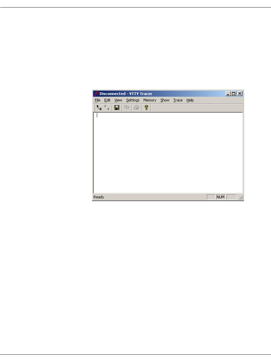
BSMI Debugging
November 2009 112
VTTY Tracer GUI
The VTTY Tracer graphical user interface provides access to control
processor internals and diagnostic tracing information from a
Windows® environment.
¾
To start the VTTY Tracer, enter:
vtty_tracer.exe
The VTTY Tracer screen is displayed.
Setting Output Options
From the main screen, you can change the tracer output options.
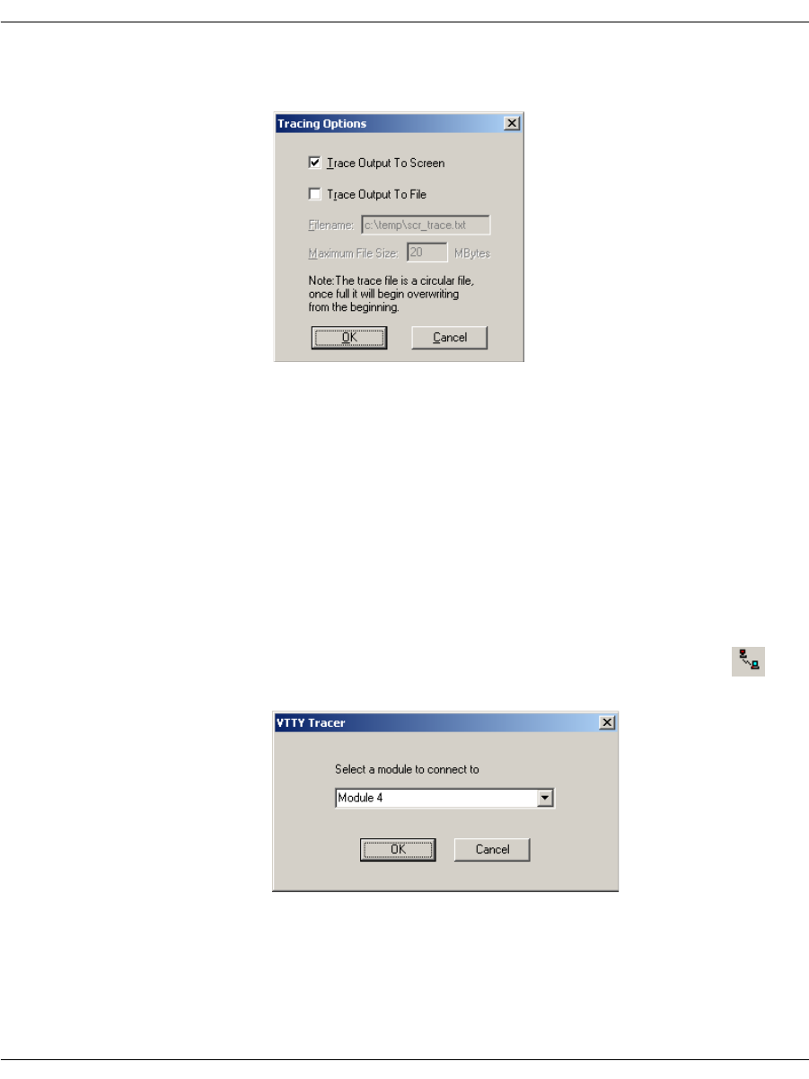
BSMI Debugging
November 2009 113
1. Click Settings|Options. The Tracing Options dialog is
displayed.
Set where the trace output is saved, either screen or file. The
maximum file size is set in MBytes. Once a file reaches its
maximum size, the tracing output loops back to the beginning of
the file. The user always has the number of MBytes of
information entered.
You can change these options any time during execution (while
tracing or before connecting to a module).
2. Click OK to save your tracing options.
Connecting to a Module
¾
Use the File menu to connect to a module:
1. Click File, Connect to Module or click on the button to
connect to the module. The VTTY Tracer dialog is displayed.
2. Choose an available module from the drop down box. The Select
a module to connect to drop down box contains a list of all
modules available on the system that are traced.
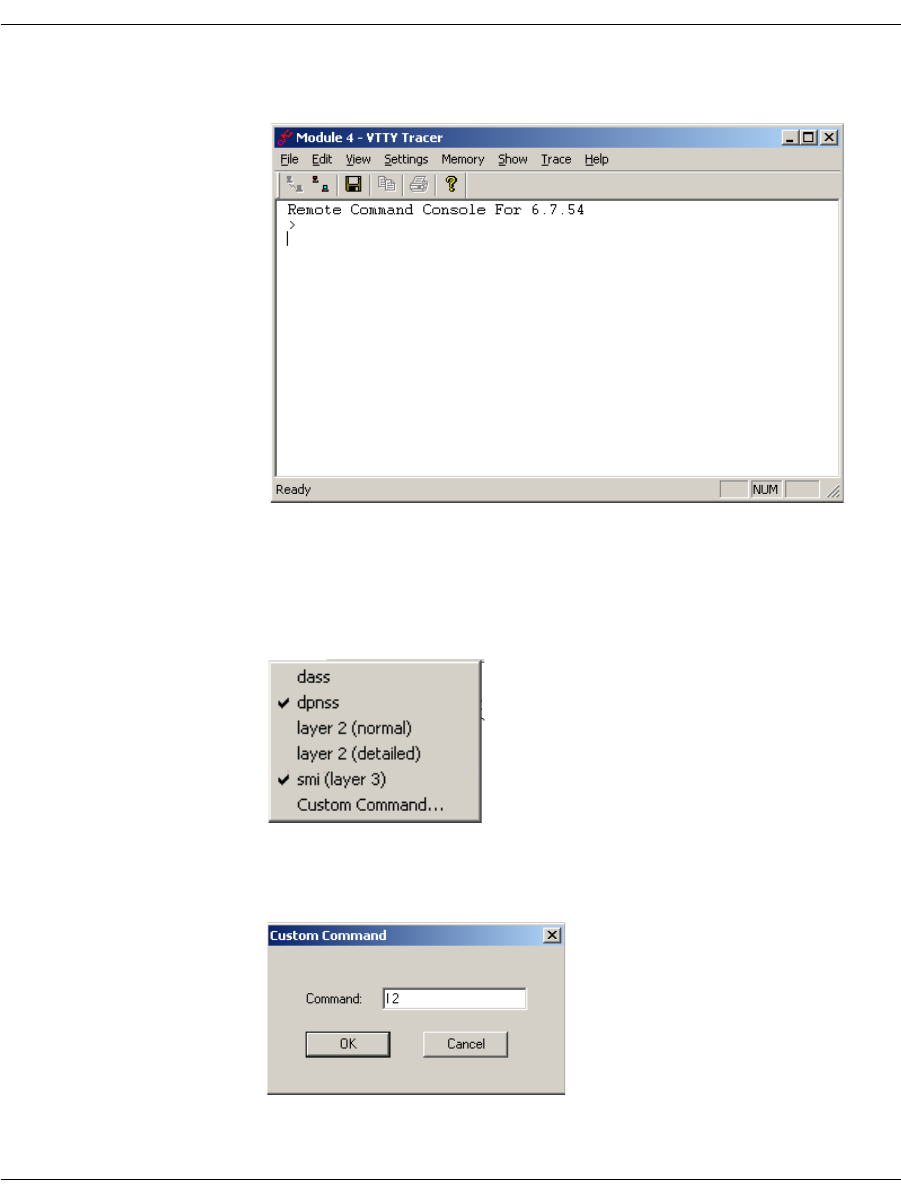
BSMI Debugging
November 2009 114
3. Click OK. The connection confirmation is displayed in the VTTY
Tracer screen:
Using the Trace Menu
When you choose options from the Trace menu, multiple items are
selected. When complete the selected items are checked, for example:
When Trace|Custom Command is selected, the Custom
Command dialog is displayed:
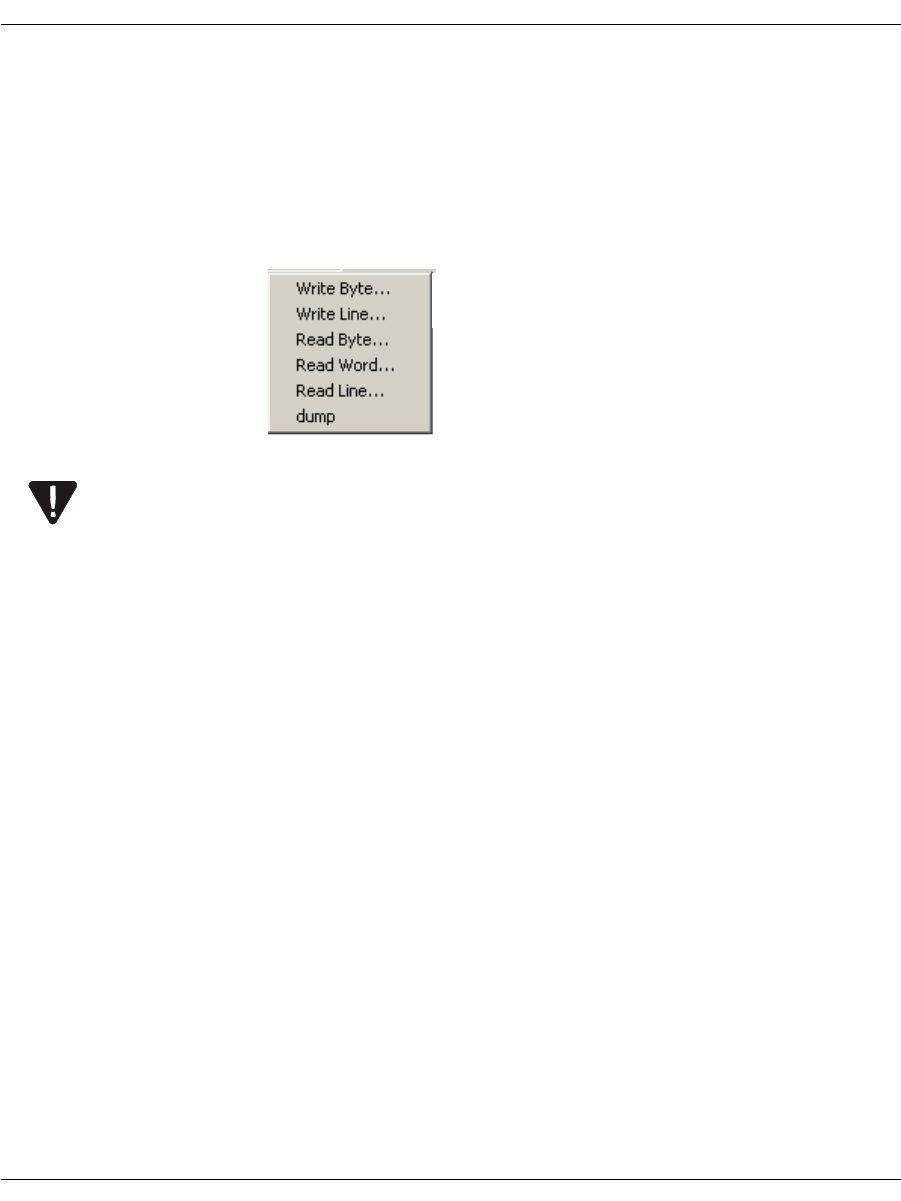
BSMI Debugging
November 2009 115
In this example the Command 12 turns on Layer 2 tracing. This
feature allows support of new tracing options without additional
coding or installation.
Using the Memory Menu
Click the Memory menu to read and write predefined sizes of
memory.
Using the Memory menu requires extreme care. Reading or writing
memory to the module can cause irreparable harm. This menu should
never be used unless explicitly directed to do so by Dialogic Technical
Services and Support. See Getting Technical Support on page 21.
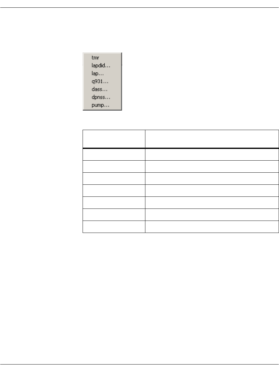
BSMI Debugging
November 2009 116
Using the Show Menu
The Show menu causes a set of predefined variables to be displayed:
Each menu choice produces a dialog box where another selection is
made from a drop down box. Once selected, output is displayed in the
main trace screen. See Figure 9.
Show Menu
Options Information About
tmr Timer structure in the call control protocols
lapdid The specified D-channel
lap The LAP-D (Q.921) protocol
q931 The Q.931 ISDN call control protocol
dass The DASS-2 call control protocol
dpnss The DPNSS-1 call control protocol
pump Internal operations
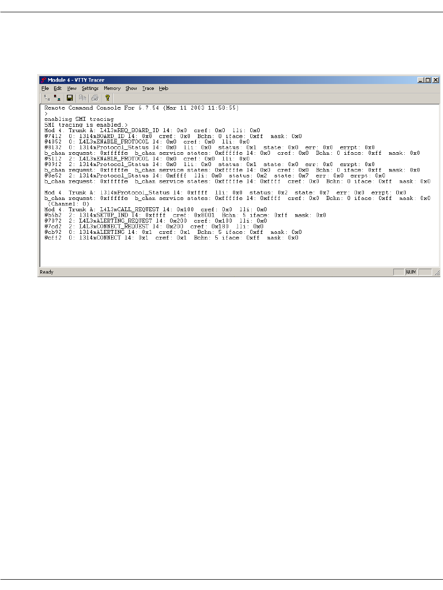
BSMI Debugging
November 2009 117
VTTY Trace Results
Figure 9 shows the results of a VTTY trace.
Figure 9. VTTY Trace Example
Each trace message (for both screen and trace file output) is prefixed
with a time stamp in the same format used for the call control trace
files and the Bfv API application debug log files.
The time reference for this time stamp is the local host time.

Call Tracer
November 2009 118
Call Tracer
Dialogic provides a Call Tracer command line utility that collects call
trace information in an active system. The output is intended for
Dialogic Technical Services and Support, but it is important that all
users know how to use Call Tracer to create the output file, if
Dialogic Technical Services and Support personnel request it. The
Call Tracer utility can be started before or after starting the client
application. If you want to trace the initialization section of the
client application, start the Call Tracer before the client application.
For information on how to start the Call Tracer, type brktcctrace -?.
Exit the Call Tracer application by typing ‘q’ or ‘Control-C’, or by
closing the command console window. The Call Tracer application
reads trace filter settings from a text configuration file called
filtersettings.cfg. The output is logged to a file name of your choosing.
For log information internal to the Call Tracer, the application
maintains its own log file that is located in the current working
directory of the application. The tracer logs all warning, error and
panic level messages by default.
The Call Tracer utility, and a sample configuration file, can be found
in the \Brooktrout\Boston\utils\winnt\bin directory when
installing the Brooktrout SDK, or in the \Brooktrout\bin directory
when installing just the System Software.
Note: Any paths in the command line argument that contain spaces
should be added between double quotes.
The Brooktrout Tracer opens ports 4010 and 4020 - 4024 by default.
BFV applications such as modinfo.exe, features.exe, and btver.exe a
Firewall dialog box will pop-up informing the user that the
application is attempting to open a port.
¾
To disable the Firewall dialog box perform one of the following:
Open ports 4010 and 4020 to 4024: Firewall configuration
Allow the applications using BFV to open the ports: Firewall
configuration
Disable the Brooktrout Tracer by setting "Number of Client
Ports" to 1 on the Brooktrout Configuration Tool Advanced Mode
in the menu Options, Tracer Connection Settings. This option is
not desired since it will prevent tracing BFV application at
runtime.

Call Tracer
November 2009 119
Command Syntax
brktcctrace [-o <path_string>] [-i <path_string>] [-t
<duration/sec>] [-x <max_file_size>] [-n <max_num_files>]
[-h]
Arguments
-o <path_string> Fully qualified path of the output file/log file including the log
filename. example: c:\Brooktrout\brktlog_xxx.txt, where xxx is the
client port number. The path containing spaces should be added
between double quotes. This is a mandatory parameter.
-i <path_string> Path of the input filter configuration file including the file name.
Path containing spaces should be added between double quotes.
-t <duration/sec> Time duration for the Call Tracer to stay connected to the clients in
seconds (default zero-infinite).
-x <max_file_size> Maximum size of the log file in Megabytes (default 1000).
-n <max_num_files> Maximum number of log- files to create (default 1).
-h Help
An example of using brktcctrace to create a call trace file:
brktcctrace -x 10 -n 5 -oc:\Brooktrout\brktlog_xxx.txt
In this case, the logging application creates the brktlog_xxx.txt file
where xxx represents the client port number. While the logging
process continues, logs are always written to the specified file until
the log file size reaches 10MB then the log file is cleared and
relogging starts all over again and saves the log file for example, as
brktlog_xxx.txt.1, brktlog_xxx.txt.2, brktlog_xxx.txt.3, etc.
Logging stops after the fifth log file has been created. When the
logging application records the fifth logging file, it then starts
overwriting the first log file for example, brktlog_xxx.txt.

Call Tracer
November 2009 120
Configuration File Format
This section describes the filter configuration file format. Because
the configuration file is optional, there is no default.
Lines that start with a ‘#’ character are comments only.
The filter settings are not case sensitive. All the settings are printed
in upper case for uniformity. If the configuration file has multiple
entries for the same filter settings, the first setting is used.
For example: If the filter settings configuration file contains the
following:
BFV.BFV.DEBUG_PRINT_CMD = OFF
BFV.BFV.DEBUG_PRINT_INTR = OFF
BFV.BFV.DEBUG_MON = OFF
BFV.BFV.DEBUG_ERR = OFF
BFV.BFV.DEBUG_PRINT_CMD = ON
then BFV.BFV.DEBUG_PRINT_CMD=OFF setting is used.

Call Tracer
November 2009 121
########################################################
Filter Settings Configuration File
########################################################
#-------------------------------------------------------
# CONFIG Legal Values
# ON - Default value will be set when a filter setting
# is not listed in the filtersettings.cfg file.
# OFF - Filter settings which are not listed in the
# filtersettings.cfg file will be disabled.
# AUTO - Default value will be set depending upon which
# side (client/server) initiated the connection.
# Client Side - Defaults will be set
# Server Side - No defaults
#-------------------------------------------------------
DEFAULT_CONFIG = AUTO
#-------------------------------------------------------
# BFV Legal Values
# ON
# OFF
#-------------------------------------------------------
BFV.BFV.DEBUG_PRINT_CMD = OFF
BFV.BFV.DEBUG_PRINT_INTR = OFF
BFV.BFV.DEBUG_MON = OFF
BFV.BFV.DEBUG_ERR = OFF
BFV.BFV.DEBUG_DEBUG = OFF
BFV.BFV.DEBUG_ACCULIB = OFF
BFV.BFV.DEBUG_ENTRY_EXIT = OFF
BFV.BFV.DEBUG_ENTRY_EXIT_ARGS = OFF

Call Tracer
November 2009 122
#-------------------------------------------------------
# ECC Legal Values
# NONE
# ERROR
# WARNING
# BASIC
# VERBOSE
#-------------------------------------------------------
ECC.ECC_API = NONE
ECC.ECC_HOST_MODULE = NONE
ECC.ECC_INTERNAL = NONE
ECC.ECC_IP_STACK = NONE
ECC.ECC_L3L4 = NONE
ECC.ECC_L4L3 = NONE
#-------------------------------------------------------
# QSIG Legal Values
# ON
# OFF
#-------------------------------------------------------
QSIG.QSIG_STACK.LAYER4_IN = OFF
QSIG.QSIG_STACK.LAYER3_IN = OFF
QSIG.QSIG_STACK.LAYER3RAW_IN = OFF
QSIG.QSIG_STACK.MAINT_IN = OFF
QSIG.QSIG_STACK.LAYER4_OUT = OFF
QSIG.QSIG_STACK.LAYER3_OUT = OFF
QSIG.QSIG_STACK.LAYER3RAW_OUT = OFF
QSIG.QSIG_STACK.MAINT_OUT = OFF

Call Tracer
November 2009 123
#-------------------------------------------------------
# VTTY Legal Values
# ON
# OFF
#
# The listed filters below use Module ID 0x02 as an
example.
# Update the module ID before using the VTTY filters.
# Add separate entries for multiple modules.
#
# There are 3 keywords that can be used in a VTTY filter
name:
# MODULE, SPAN, and CHAN. The index for each of the
keywords
# is base 0. The table below shows which keywords are
available
# for which filters. The VTTY_ filter name prefix is not
shown.
#
# MAIN | CAS | DCHAN | HDLC | LE58
# ______________________________________________
#
# MODULE | MODULE | MODULE | MODULE | MODULE
# | SPAN | SPAN | SPAN | SPAN
# | CHAN* | | |
#
#
# * CAS only uses CHAN on digital modules, not on analog.
# The module 2 in the example below is therefore a
digital
# board.
#
# Possible generic names:
# VTTY_MODULE.MODULEn.<filtername>.<settingname>
# VTTY_SPAN.MODULEn.SPANn.<filtername>.<settingname>
#
VTTY_CHAN.MODULEn.SPANn.CHANn.<filtername>.<settingname>

Call Tracer
November 2009 124
#
# So to trace SMI for module 2 add:
# VTTY_MODULE.MODULE02.VTTY_MAIN.SMI = ON
#
# To trace CAS L3L4 for module 2 on span1, channel 1 add:
# VTTY_CHAN.MODULE02.SPAN01.CHAN01.VTTY_CAS.L3L4 = ON
#
# Refer to the developer guide for additional usage
# information.
#-------------------------------------------------------
VTTY_MODULE.MODULE02.VTTY_MAIN.LAP = OFF
VTTY_MODULE.MODULE02.VTTY_MAIN.SMI = OFF
VTTY_MODULE.MODULE02.VTTY_CAS.CALLERID = OFF
VTTY_MODULE.MODULE02.VTTY_CAS.COMMANDS = OFF
VTTY_MODULE.MODULE02.VTTY_CAS.DEGLITCHER = OFF
VTTY_MODULE.MODULE02.VTTY_CAS.DIAL = OFF
VTTY_MODULE.MODULE02.VTTY_CAS.ERRORS = OFF
VTTY_MODULE.MODULE02.VTTY_CAS.EVENT_TIME = OFF
VTTY_MODULE.MODULE02.VTTY_CAS.EVENTS = OFF
VTTY_MODULE.MODULE02.VTTY_CAS.FACILITY_ACCESS = OFF
VTTY_MODULE.MODULE02.VTTY_CAS.L3L4 = OFF
VTTY_MODULE.MODULE02.VTTY_CAS.NETWORK_STATUS = OFF
VTTY_MODULE.MODULE02.VTTY_CAS.RING_COUNT = OFF
VTTY_MODULE.MODULE02.VTTY_CAS.STATES = OFF
VTTY_MODULE.MODULE02.VTTY_CAS.TIMER = OFF
VTTY_MODULE.MODULE02.VTTY_DCHAN.EX = OFF
VTTY_MODULE.MODULE02.VTTY_DCHAN.ST = OFF
VTTY_MODULE.MODULE02.VTTY_DCHAN.EV = OFF
VTTY_MODULE.MODULE02.VTTY_DCHAN.BF = OFF
VTTY_MODULE.MODULE02.VTTY_HDLC.RCV = OFF
VTTY_MODULE.MODULE02.VTTY_HDLC.XMIT = OFF

Call Tracer
November 2009 125
VTTY_MODULE.MODULE02.VTTY_LE58.CONFIG = OFF
VTTY_MODULE.MODULE02.VTTY_LE58.CURRENT_TIME = OFF
VTTY_MODULE.MODULE02.VTTY_LE58.DEVICE_MGMT = OFF
VTTY_MODULE.MODULE02.VTTY_LE58.EXCEPTION = OFF
VTTY_MODULE.MODULE02.VTTY_LE58.HW_ACCESS = OFF
VTTY_MODULE.MODULE02.VTTY_LE58.LINE_STATUS = OFF
VTTY_MODULE.MODULE02.VTTY_LE58.RING_COUNT = OFF
VTTY_MODULE.MODULE02.VTTY_LE58.SIGNALING = OFF
########################################################

November 2009 127
4 - Sample Applications and Utilities
This chapter describes the sample applications and utilities that
come as part of the Dialogic® Brooktrout® SDK.
Dialogic includes a large collection of sample application programs
and utilities with the Bfv API modules.
Sources for the sample applications are located in either
boston/bfv.api/app.src or boston/bfv.api/bapp.src, except for a few
applications whose directories are stated in the text. The application
makefiles appear and compilation is performed in either
boston/bfv.api/<platform>/app.src or
boston/bfv.api/<platform>/bapp.src (where <platform> represents
the name of the operating system in use). Many of the bapp.src
program executables are also distributed in this directory.
The chapter has the following sections:
An alphabetical list of all the sample applications
Compiling Sample Applications Using Makefiles
boardmon
The boardmon program monitors the condition of a module. It
provide Ethernet link status (as determined by BfvBoardNotify)
when monitoring a board with an enabled Ethernet interface.It
displays the module temperature, the status of the Ethernet port
and monitors one or more telephony spans on the module. It reports

boardmon
November 2009 128
the state of the signaling bits and alarms. It also counts the errors
(e.g., framing errors, CRC errors, clock slips, BPVs) on each span. It
only works with spans that are configured for robbed-bit signaling
and where telephony connections have been made.
The spans are numbered starting from 1 which is the first interface
on a module.
The btcall.cfg file is the user configuration file. The boardmon
application is found in the bapp.src directory.
Command Syntax
boardmon [-m <mod>] [-s <span>] [-d] [-v] [-h]
While the program is running you can press a key to reset the error
counters or to quit. When running under Unix, you must press
Enter after pressing the key.
Arguments
-m <mod> Use specified module (default 2)
-s <span> Use specified span only [1-4] (default all)
-d Enable program debug mode
-v Enable Bfv API debug mode
-h Help
1 Reset error counters for span 1
2 Reset error counters for span 2
3 Reset error counters for span 3
4 Reset error counters for span 4
r or R Reset error counters for all spans
q or Q Quit the program

btver
November 2009 129
Sample boardmon Output
Board Temperature: 105.8F 41.0C
Ethernet link 0: UP
Mod 0x03 Span 1 No Alarms FRM 000000 CRC 000000 BPV 000000 SLIP 000000
Ch: 1 5 9 13 17 21 Last reset: 11/30 14:42:11
In: a.aa .aaa aaaa .aaa aa.a aaa.
b.bb .bbb bbbb .bbb bb.b bbb.
c.cc .ccc cccc .ccc cc.c ccc.
d.dd .ddd dddd .ddd dd.d ddd.
Out: A.AA .AAA AAAA .AAA AA.A AAA.
B.BB .BBB BBBB .BBB BB.B BBB.
C.CC .CCC CCCC .CCC CC.C CCC.
D.DD .DDD DDDD .DDD DD.D DDD.
Mod 0x03 Span 2 LOS FRM 000002 CRC 000000 BPV 000000 SLIP 000001
Ch: 1 5 9 13 17 21 Last reset: 11/30 14:42:11
In: aa.. .... .... .... .... ....
bb.. .... .... .... .... ....
cc.. .... .... .... .... ....
dd.. .... .... .... .... ....
Out: AA.. .... .... .... .... ....
BB.. .... .... .... .... ....
CC.. .... .... .... .... ....
DD.. .... .... .... .... ....
btver
The btver program displays version information for the driver, Bfv
API, boot ROM firmware, control processor firmware, and DSP
firmware.
The btcall.cfg file is the user configuration file. The btver program is
found in the bapp.src directory. Turn on the Bfv API debug program
from the command line.

connlist
November 2009 130
Command Syntax
btver [-m <mod>] [-v]
The firmware must be downloaded on a module to obtain its control
processor and DSP information.
connlist
The connlist program lists currently established call switching
connections. Full-duplex connections are always reported as a pair of
simplex TRANSMIT-ONLY connections, where the source and
destination endpoints are swapped for the two halves of the
full-duplex connection.
Turn on the Bfv API debug program from the command line. The
btcall.cfg file is the user configuration file. The connlist program is
found in the bapp.src directory.
Command Syntax
connlist [-m <mod>] [-v]
A receive connection between two given points is identical to a
transmit connection between those same points with the source and
destination interchanged.
Arguments
-m <mod> Display version info for specified module only.
Otherwise display for all.
-v Turn on Bfv API debug mode.
Arguments
-m <mod> Module number for connections (default 2).
-v Turn on Bfv API debug mode.

csend
November 2009 131
csend
This application uses low-level, noninfopkt, raw-data, fax-sending
routines to send facsimiles. It allows sending a single fax page either
in standard fax format from an MH/MSB G3 data file or in an
enhanced fax format (e.g. JPEG, JBIG) from an EFF data file. T.30
holdup is used to check on the receiver's capabilities before deciding
which type of file to send.
Turn on the Bfv API debug program from the command line. The
btcall.cfg file is the configuration file. The csend program is found in
the app.src directory.
Command Syntax
csend [-u <unitno>] [-v] [-c <EFF_file>] [-g <G3 file>]
[-e <EFF_OPT>] <phone number>

deact
November 2009 132
deact
The deact program deactivates a hardware module, marking it as
dead.
Bfv API debug mode is turned on. The btcall.cfg file is the user
configuration file. The deact program is found in the bapp.src
directory.
Arguments
-c <EFF_file> Color or other enhanced fax file, default: c1.jpg
-e <EFF_opt> Enhanced Fax Format (EFF) options, default: 3
OR together the following hex values:
1 = JPEG Enable
2 = Full Color
4 = Default tables
8 = 12-bit (vs. 8-bit)
10 = No Subsampling
20 = Custom Illuminant
40 = Custom Gamut
100 = JBIG
200 = JBIG L0
400 = Lossless Color
800 = MRC
1000 = MRC
2000 = MRC
4000 = Plane Interleave
8000 = Page Length Strip
-g <G3 file> Black and white MH file, default: eagle.301
<phone number> The telephone number to call.
-u <unitnum> Use specified channel number.
-v Turn on Bfv API debug mode.

deact
November 2009 133
Command Syntax
deact [-a] [-s] <mod>
Arguments
-a Deactivate all modules on the board containing
<mod>.
-s The value of <mod> is interpreted as a cPCI slot
number.
<mod> Module to deactivate.

debug_control
November 2009 134
debug_control
The debug_control utility allows a user to selectively turn on logging
remotely in an application. The application gives the user the ability
to control all the debug options available in the
BfvDebugModeSetAdv function.
Command Syntax
debug_control [-v] [-u chan]
[-d debug_mode [-f file1 [-f file2 [-m max_size]]]]
[-F 0|1 [-a]]
[-c debug_type[,...] [-l level] [-L file]]
At least one of -d, -F, or -c is required.
The -u option is required for -d and -F.
Arguments
-d = Set Bfv API debug mode, optionally with file or
files with limit.
debug_mode = Numerical debug mode value used with
BfvDebugModeSet (for example, 255)
-F = Turn on function entry/exit debugging, optionally
with arguments:
1 - enable
0 - disable
-a - use arguments
-c = Turn on call control debugging, optionally with
level or file.
debug_type = api | l3l4 | l4l3 | int | host | ip (one
or more)
level = none | error | warning | basic |
verbose(default)
-v = Turn on local Bfv API debug mode.

decode
November 2009 135
decode
The decode program reads a specified infopkt stream file and lists
the individual infopkts that comprise the stream.
The decode program is found in the app.src directory.
Command Syntax
decode [-f] <filename>
Example
decode filename.ips
Arguments
-f Directs decode to follow indirect infopkts and
decode the contents, instead of listing file names.
<filename> The name of the infopkt stream file to read.

dfax
November 2009 136
dfax
The dfax program uses the low-level Intel DCX fax transmitting and
receiving routines to send and receive facsimiles.
Turn on the Bfv API debug program from the command line. The
btcall.cfg file is the user configuration file. The dfax program is
found in the app.src directory.
Command Syntax
dfax [-u <unitno>] [-v] -s <phoneno> <dcx_file>
or
dfax [-u <unitno>] [-v] -r <dcx_file>
divert
The divert program waits for an incoming call from a caller. It then
can do several things:
1. Set the -d num option to divert the call to a given number by
calling BfvLineDivert() to the diverted-to caller and providing a
reason specified by option -e. Option -s specifies the channel
number of the line to use for the call to the diverted-to caller. If
option -s is not specified, Bfv picks the first available channel
number on the same module of the channel number specified in
option -u.
2. If option -d is not specified and the incoming call is a diverted-to
call, option -j rejects this diverted-to call. If option -j is not
specified, the software accepts the call. The diverted-to call is
determined by the value of args_cc.cres.redir_reason being equal
to DIVERT_NONE (0).
Arguments
<dcx_file> The name of the file to send or receive.
-r Receive mode.
-s <phoneno> Send to the specified phone number.
-u <unitno> Channel number.
-v Turn on Bfv API debug mode.

dlfax
November 2009 137
3. If the incoming call is accepted, the divert program uses the
speed_infopkt_file recording and playing routines to record and
play speech.
Command Syntax
divert [-d <num>] [-e <reason>] -j [-u <unitnum>]
[-s <unitnum>] <infopkt_file> -p -r
dlfax
The dlfax program uses the highest level infopkt sending routines to
send facsimiles and the dialing database functions to implement
dialing restrictions. If you include the -c argument, the application
uses the dialing restrictions of the specified country. If you include
the -l argument, the application only lists the contents of the
dialing database; it does not dial.
Note: If you change the country code between runs of the dlfax
sample, it can cause incorrect blacklisting of phone numbers.
When you change the country code, delete the dialdb file
created by the sample.
Pre-blacklisted numbers do not work when using the -c option. To
test this functionality, set the country code in the user configuration
file to the desired country.
Arguments
-d <num> Divert to a given number, or else wait for a
diverted-to call.
-e <reason> If -d, then -e specifies the redir_reason (default
is DIVERT_UNCONDITIONAL).
-j If waiting for a diverted-to call, reject the
diverted-to call.
-u <unitnum> Use specified unit number.
-s <unitnum> Use specified unit number for second LP.
<infopkt_file> Name of the file to play or record to.
-p Play.
-r Record. The default is 10 seconds.

dstrip
November 2009 138
Bfv API debug mode is turned on. The btcall.cfg file is the user
configuration file. The dlfax program is found in the app.src
directory.
Command Syntax
dlfax -l
or
dlfax [options] <infopkt file>
dstrip
The dstrip program writes out individual PCX pages from a DCX
file. The first page is written to g3data.301, the second to
g3data.302, and so on, until all of the pages are written.
This utility converts image data stored in a DCX file to raw PCX
format. It is typically used with one of the utilities described in
Appendix A, G3 Legacy Utilities on page 408.
The dstrip program is found in the app.src directory.
Command Syntax
dstrip [-o <output_base>]<dcx_filename>
Arguments
-c <ccode> Use the dialing restrictions for the
country specified by ccode. This value
must be one of the numeric values listed
in ccode.h.
<infopkt file> The name of the infopkt file to send.
-l List contents of the dialing database.
-s <num> Send to given phone number.
-u <unitnum> Use specified channel number.
Arguments
<dcx_filename> Specify the name of the DCX file to convert to
PCX format.
-o <output_base> Use the supplied output filename base to
form filenames instead of “g3data”.

eccllvoice
November 2009 139
eccllvoice
The eccllvoice program is used to record and play speech for ISDN
calls. It uses the speech-infopkt-file recording and playing routines
to record and play speech. Recording continues for a maximum of ten
seconds or the time specified in the -n option.
eccllvoice uses low-level call control function calls as shown in the
following table.
ISDN mode is established by calling BfvLineReset and including a
call control configuration file. The name of the call control
configuration file (default callctrl.cfg) must be included in the
user-defined configuration file (default btcall.cfg). See Volume 6 of
the Bfv API Reference Manual for information about setting up a call
control configuration file.
Pressing # on the telephone keypad immediately terminates
playback or recording.
Pressing the following keys on the telephone keypad affect the speed
and volume at which the application plays back speech:
1 = increases the gain
2 = decreases the gain
3 = increases the speed
4 = decreases the speed
Turn on the Bfv API debug program from the command line. The
btcall.cfg file is the user configuration file. The eccllvoice program is
found in the app.src directory.
In Place Of: Functions Used:
BfvCallReject BfvCallDisconnect
BfvCallWaitForRelease
BfvLineOriginateCall BfvCallSetup
BfvCallWaitForComplete
BfvLineWaitForCall BfvCallRingDetect
BfvCallWaitForSetup
BfvLineAnswer BfvCallAccept
BfvCallWaitForAccept
BfvLineTerminateCall BfvCallDisconnect
BfvCallWaitForRelease

fax
November 2009 140
Command Syntax
eccllvoice [options] infopktfile
Requires one -p or -r argument.
fax
The fax program uses the highest level infopkt file fax sending and
receiving routines to send or receive facsimiles. The local ID is
specified from the command line. (This application is very similar to
faxhl.c.)
Bfv API debug mode is turned on. The btcall.cfg file is the user
configuration file. The fax program is found in the app.src directory.
Arguments
-c <num> Call given number, else wait for ring.
-f Specify record coding format1; use the number of
the format or one of the following names. If there
is no number specified, you must use the name.
1. Not all coding formats and rate combinations are available on all
products.
adpcm
adpcm32
adpcm24
pcm_ulaw
pcm_ulaw64
pcm_ulaw48
pcm_ulaw88
pcm_alaw
pcm_alaw64
pcm_alaw48
pcm_alaw88
1
2
3
-l Loop forever, sending or receiving.
-n <secs> Specify recording time in seconds.
-p Play.
-r Record (default 10 seconds).
-u <unitnum> Use specified channel.
-v Enable Bfv API debug mode.

faxhl
November 2009 141
Command Syntax
fax [options] <infopktfile>
Requires one -s or -r argument.
faxhl
The faxhl program uses the highest level infopkt file fax sending and
receiving routines to send or receive facsimiles. The local ID is
specified from the command line. This application is very similar to
fax.c.
Turn on the Bfv API debug program from the command line. The
btcall.cfg file is the user configuration file. The faxhl program is
found in the app.src directory.
Command Syntax
faxhl [options] <infopktfile>
Requires one -s or -r argument.
Arguments
<infopktfile> Name of the file to send or receive.
-l <string> Set local ID.
-L Loop for testing.
-r Receive a fax.
-s <num> Send to given phone number.
-u <unitnum> Use specific channel number.
-w On receive, do not wait for ring.
Arguments
<infopktfile> Name of the file to send or receive.
-l <string> Set local ID.
-r Receive a fax.
-s <num> Send to given phone number.
-u <unitum> Use specific channel number.
-v Turn on Bfv API debug mode.

faxll
November 2009 142
faxll
The faxll program uses the low-level non-infopkt raw data fax
sending and receiving routines to send or receive facsimiles. This
application uses the BfvFaxSendFile function, so 128-byte
Brooktrout headers are not permitted. It also uses the user function
feature of BfvLineOriginateCall to print call progress values.
Use the -g or -a argument to specify that the next raw data file
contains G3 or ASCII data, respectively. If a file contains fine
resolution data, use the -F argument. Use the -b argument to
specify a page break.
Turn on the Bfv API debug program from the command line. The
btcall.cfg file is the user configuration file. The faxll program is
found in the app.src directory.

faxll
November 2009 143
Command Syntax
faxll [-u <unitno>] [-v] [-h] [-H] -s <phoneno>
[-F] [-E #] [-g] [-a] [-p] <file> [-b] ...
or
faxll [-u <unitno>] [-v] [-p] -r <g3file> ...
Arguments
-a <files> The following files are raw ASCII text.
-b Beginning of page.
-E # The next page is an enhanced fax format page.
# specifies the format, which is created by ORing the
following hex values:
1 = JPEG Enable
2 = Full Color
4 = Default tables
8 = 12bit (vs. 8bit)
10 = No Subsampling
20 = Custom Illuminant
40 = Custom Gamut
100 = JBIG
200 = JBIG L0
400 = Lossless Color
800,1000,2000 = MRC
4000 = Plane Interleave
8000 = Page Length Strip
-F The next page is fine resolution, otherwise normal.
-g The following files are raw G3 data (default).
<g3file> Name of the file to receive.
-h/-H Insert a page header.
-p The following files are raw PCX data or receive PCX
data.
-r Receive mode.
-s <phoneno> Send to the specified phone number.
-u <unitno> Unit number.
-v Turn on Bfv API debug mode.

faxml
November 2009 144
When sending, the application can mix G3 and ASCII files.
Example
-g f1 f2 -a f3 -b -g f4
When receiving, each filename in the list receives a page of G3 data,
so make sure that enough filenames appear in the list to
accommodate all pages of incoming data.
faxml
The faxml program uses the mid-level infopkt file fax sending and
receiving routines to send or receive facsimiles.
Turn on the Bfv API debug program from the command line. The
btcall.cfg file is the user configuration file. The faxml program is
found in the app.src directory.
Command Syntax
faxml[-u <unitno>][-v] -s <phoneno> <infopktfile>
or
faxml[-u <unitno>][-v] -r <infopktfile>
Arguments
<infopktfile> Name of the file to send or receive.
-r Receive mode.
-s <phonenum> Send to the specified phone number.
-u <unitno> Unit number.
-v Turn on Bfv API debug mode.

faxp
November 2009 145
faxp
The faxp program uses the highest level infopkt file fax polling
routines to send and/or receive facsimiles. You must specify if the
program is going to call (-c) or answer (-a) and one send file (-s),
one receive file (-r), or one of both.
This program performs the ordinary sending and receiving functions
and all possible polling variations. The local ID is specified from the
command line.
Bfv API debug mode is turned on. The btcall.cfg file is the user
configuration file. The faxp program is found in the app.src directory.
Command Syntax
faxp [options]
Requires one -c or -a argument and one -s or -r argument or one
of each.
faxpml
The faxpml program uses the medium level infopkt file fax polling
routines to send and/or receive facsimiles. It performs ordinary
sending and receiving functions and all polling variations. Users can
enter the local ID at the command line.
Bfv API debug mode is turned on. The btcall.cfg file is the user
configuration file.
The faxpml program is found in the app.src directory.
Arguments
-a Answer.
-c <num> Dial given phone number.
-L Loop for testing.
-r <infopktfile> File to receive, if permitted.
-s <infopktfile> File to send, if permitted.
-u <unitnum> Use specified channel.

feature
November 2009 146
Command Syntax
faxpml [options]
Requires one -s or one -r argument or one of each, and one -c or
one -a argument.
feature
The feature program manipulates feature set data on the product. It
can query or download feature set data.
Feature set data contains licensing information specific to a given
module. The licensing information contains information as to what
features the user can access, how many channels are available, etc.
The btcall.cfg file is the user configuration file. The feature program
is found in the bapp.src directory. Turn on the Bfv API debug
program from the command line.
Command Syntax
feature [-m <mod>] <action>
Arguments
-a Answer.
-c <num> Dial given phone number.
-L Loop for testing.
-r <infopktfile> File to receive, if permitted.
-s <infopktfile> File to send, if permitted.
-u <unitnum> Use specified channel number.
Arguments
-m <mod> Apply action to specified module (default 2)
Actions
-d <feature_file> Download ASCII feature file.
-b Perform download using binary file.
-q Query loaded feature set.
-v Enable Bfv API debug mode.

feature
November 2009 147
feature downloads ASCII license (feature) files by default, and can
also accept binary data if you use the -b option.

firm
November 2009 148
firm
The firm program is used to download firmware. The firmware
consists of several types, by number, which must be downloaded in
the proper sequence. firmload automatically takes care of identifying
the proper files and downloading them in the correct sequence.
The sequence is as follows:
Type 2 (PROC_APP) = Control processor firmware
Type 1 (DSP_APP) = DSP firmware
Bfv API debug mode is turned on. The btcall.cfg file is the user
configuration file. The firm program is found in the bapp.src
directory.
Command Syntax
firm [-m <mod>] [-c <conf_spec>] -t <type>
<firmware_file>
If the download type is 2 (PROC_APP), the driver attempts to
reestablish communications with the destination module. If the
module was previously marked as dead, it might become usable
again.
Arguments
-m <mod> Module number to download to (default 2)
-c <conf_spec> Firmware configuration specification number.
This is reported by modinfo -c. This only
applies to PROC_APP firmware. The current
meaning of the configuration specification
value is the number of channels for which to
configure the firmware.
-t <type> Type of firmware downloaded:
1 = DSP_APP
2 = PROC_APP
<firmware_file> Firmware file to download

firmload
November 2009 149
firmload
The firmload program is used to download a complete set of
standard firmware files to all hardware modules on all boards in a
system. The standard firmware files are listed in Chapter 9 in the
installation and configuration guide that came with your software
and in the Release Notes. Downloads, by default, are attempted for
all hardware modules in the range 2 through 0xFD.
The firmware consists of several types, by number, that must be
downloaded in the proper sequence. firmload automatically takes
care of identifying the proper files and downloading them in the
correct sequence.
The sequence is as follows:
Type 2 (PROC_APP) = Control processor firmware
Type 1 (DSP_APP) = DSP firmware
Bfv API debug mode is turned on. The firmload program is found in
the bapp.src directory.
This program was previously a script/batch file. The old version of
firmload is supplied as firmload_old in the bapp.src directory.
Command Syntax
firmload [-c <conf_spec>] [-d] [-b 0|1][-q] [-e] <firmware_dir> [<module_num>
...]
Arguments
-c <conf_spec> Firmware configuration specification number. This
is reported by modinfo -c. This only applies to
PROC_APP firmware. The current meaning of the
configuration specification value is the number of
channels to configure the firmware.
-d Do not download the DSP firmware.
-q Quiet mode (disable Bfv API debug mode).
-e Stop on the first error. Normally download
continues through the entire available module
sequence.
<firmware_dir> Directory containing firmware files.
<module_num> Optional module numbers that have firmware
downloaded.

font
November 2009 150
The firmload program ensures that the required firmware files exist
in the specified directory before beginning a download. There are
multiple possibilities for some of the firmware filenames. These are
listed in the following list in search order. firmload looks for the
following:
Example
firmload Brooktrout/boston/fw
font
The font program downloads ASCII fonts for fax transmission and
reports on font download status.
Turn on the Bfv API debug program from the command line. The
btcall.cfg file is the user configuration file. The font program is found
in the bapp.src directory.
Command Syntax
font [-m <mod>] [-q] [-d] [-v]
One of -q or -d is required. When -d is specified, fonts are
downloaded as specified in the user configuration file, btcall.cfg. Up
to seven user fonts (0 - 6) and a default font (255) are downloaded.
Firmware Type Filename
PROC_APP cp.bin
DSP_APP dsp1000.hex, dsp1000_ld.hex, dsp1000_v34.hex
Arguments
-m <mod> Use specified module (default 2).
-q Report download status of fonts.
-d Download fonts as specified in btcall.cfg.
-v Turn on Bfv API debug mode.

ipstrip
November 2009 151
ipstrip
The ipstrip program removes the infopkt header from the G3 or
speech data in a specified infopkt stream file and writes each page of
the converted data to a file, g3data.30x. The first page of converted
data is written to the file g3data.301, the second to the file
g3data.302, the third to the file g3data.303, and so on until the
entire infopkt stream file is converted. All speech data is placed in a
single file.
This utility is typically used to convert:
Received fax data previously converted to an infopkt stream file
back to G3 format.
(See mkinfopk on page 153 for detailed information on how to
create an infopkt stream file.)
Speech data recorded using the BfvSpeechRecord function to a
raw speech format.
The ipstrip program is found in the app.src directory.
Command Syntax
ipstrip [-h] [-o <output_base>] <filename>
Arguments
-h Puts a 128-byte Brooktrout header at the
beginning of each file. The addition of this
header causes the utility to store the resolution
and width of each page within the file.
-o <output_base> Uses supplied output filename base to form
filenames instead of “g3data”.
<filename> Specifies the name of the infopkt stream file,
consisting of packetized G3 or speech data, to
convert to raw format.

ivr
November 2009 152
ivr
The ivr program is a small, interactive, voice-response system that
permits users to receive a fax, send a fax, record a message and play
a message. It uses the speech infopkt-file recording and playing
routines and the highest level infopkt-file fax receiving and sending
routines.
The ivr_msg subdirectory contains all prerecorded files, and all new
files are created in that subdirectory.
Bfv API debug mode is turned on. The btcall.cfg file is the user
configuration file. The ivr program is found in the app.src directory.
Command Syntax
ivr [options]
mkdcx
The mkdcx program creates a DCX file from a collection of raw PCX
files.
The mkdcx program is found in the app.src directory.
Command Syntax
mkdcx -o <dcx_file> <pcxfilename>...
Arguments
-L Loop for testing.
-u <unitnum> Channel number.
Arguments
-o <dcx_file> The name of the output DCX file.
<pcxfilename> The name of one of the input raw PCX files that
is one of the pages of the DCX file. Any number
of pcxfilename arguments are permitted.

mkinfopk
November 2009 153
mkinfopk
The mkinfopk program builds an infopkt stream file.
The mkinfopk program is found in the app.src directory.
Command Syntax
mkinfopk -o <output_fname> [-i <input_fname>]
{infopkt_type arg}...
The type infopkt_type is indicated by one of the following:
Arguments
-o <output_fname> The name of the output file.
-i <input_fname> Infopkt type specifications are included in the
file input_fname instead of the command line.
infopkt_type The type of infopkt that follows.
arg An argument value for the infopkt. Depending
on the corresponding infopkt_type, arg is
either a filename or a dummy value.
Data type ascii, g3, speech, and annot.
For data and indirect infopkts, the required
argument is a filename.
The annot type infopkt accepts either an ASCII
filename or the argument @. If you pass mkinfopk
the argument @, mkinfopk prompts you to enter a
text annotation.
Indirect type indir[infopkt], indirascii, indirg3,
indirtiff, indirspeech, indirdcx, and
indirwave.
Note: The word indir is an abbreviation for
indirinfopkt.

mkinfopk
November 2009 154
At least one space must be inserted between each command line
argument. If you enter mkinfopk at the command line without
specifying any arguments, mkinfopk displays a list of all the possible
arguments.
An example of using mkinfopk to create an infopkt stream file:
mkinfopk -o faxstrem.ips doc @ g3_strip 1
indirg3 letrhead.g3 g3_strip 1 indirg3 salute.g3
ascii_strip 1 ascii letrbody.asc g3_strip 1
indirg3 signatur.g3
Note: 1 is a dummy value when it follows the g3_strip and other
infopkts.
Tag type doc, g3_strip, ascii_strip, page, t30, bop,
spi, eos, fax_hdr, eff.
For tag (parameter setting) infopkts, the
argument value is not normally used, and
mkinfopk inserts a dummy value. When you do
not specify an argument value, mkinfopk uses
hard-coded default parameter values. If, however,
arg is the @ character, mkinfopk prompts you to
enter parameter values for this infopkt. (The bop
type does not have parameters, so the @ character
has no effect on it.) When you specify the
fax_hdr infopkt type, mkinfopk prompts you for
the label format text, whether or not @ is used.
For a fax infopkt stream file, the first infopkt type
must be doc.
For a speech infopkt stream file, the first infopkt
type must be spi.

mkprompt
November 2009 155
mkprompt
The mkprompt program creates or updates a prompt file from
infopkt files that contain individual phrases. When updating, you
can specify an existing phrase number or a new phrase number.
The mkprompt program is found in the app.src directory.
Command Syntax
mkprompt <prompt_file> [<phrase_ipkt>]...
or
mkprompt -u <phrase_num> <prompt_file> <phrase_ipkt>
mktiff
The mktiff program creates a TIFF-F file from a collection of raw
G3 files in MH/MSB format with EOLs byte-aligned.
The mktiff program is found in the app.src directory.
Command Syntax
mktiff -o <tiff_file> <g3filename>...
Arguments
<prompt_file> Name of the prompt file to create or
update.
<phrase_ipkt> Name(s) of the infopkt file(s) to use for
creating or updating the prompt file.
-u <phrase_num> Update phrase_num; otherwise create.
Arguments
-o <tiff_file> Is the name of the output TIFF-F file.
<g3filename> Is the name of one of the input raw G3 files that is
one of the pages of the TIFF file. Any number of
g3filename arguments are permitted.

modinfo
November 2009 156
If a raw G3 file has a 128-byte Brooktrout header (it is a btG3 file),
mktiff uses the resolution, width, and number of scan lines from the
header when storing the information for that page in the new TIFF
file. If it does not encounter a header or if the number of scan lines is
0, mktiff counts the actual number of scan lines in the G3 input file.
modinfo
The modinfo program lists information about active hardware and
software modules maintained within the driver.
The modinfo program is found in the bapp.src directory.
Command Syntax
modinfo [-p] [-c] [-s] [-h] [-H] [-a] [mod]
Each module found is listed, along with whatever hardware or
channel information is available. If a module has been marked by
the driver as dead, it is listed as *DEAD*.
Configuration values shown when using the -c option is supplied to
firm or firmload applications when downloading type 2 (PROC_APP)
firmware.
Configuration information from the module’s PCI configuration
space is displayed using the -p option.
The number of channels listed is the total number of channels
supported by the module, including its administrative channel. The
total is normally one more than the number of work channels, which
are mapped into ordinal channel numbers.
Argument
-p List PCI configuration information.
-c List firmware configuration options.
mod Module number whose status is to be
printed, otherwise all.
-s Display cPCI slot and CPU information.
-h Display hardware resource information.
-H Display the hardware information reported
by the firmware.
-a Use all previous options.

playp
November 2009 157
For example, a module with 48 work channels is listed as having 49
channels, and a module with no work channels (no firmware
downloaded) is listed as having one channel.
playp
The playp program waits for a call, then plays the specified sequence
of phrases from the specified prompt file until the sequence
completes or until the user presses the # key.
Bfv API debug mode is turned on. The btcall.cfg file is the user
configuration file. The playp program is found in the app.src
directory.
Command Syntax
playp [-u <unit>] <prompt_file> <phrase_num>...
rtp
The rtp/rtcp program displays the information in received
RTP/RTCP events on an individual channel or on all channels.
Turn on the Bfv API debug program from the command line. The
btcall.cfg file is the configuration file. The rtp/rtcp program is found
in the app.src directory.
Command Syntax
rtp [-u <unitno>] [-v]
or
rtp [-a] [-v]
Arguments
-u <unit> Channel number (default is 0).
<prompt_file> File from which to play the phrase.
<phrase_num> Phrase number or numbers to play.

shoparam
November 2009 158
Arguments
-a All Channels
-u <unitno> Channel number.
-v Turn on Bfv API debug mode.
shoparam
The shoparam program displays the contents of the line structure
and the parameter values set in a user configuration file and the
read-only parameters taken from the country configuration file.
shoparam does not work unless a module is present in the system,
the driver is installed and running, and the firmware is loaded and
running on the module.
The shoparam program is found in the app.src directory.
Command Syntax
shoparam <user configuration filename>
telreset
The telreset program resets the telephony configuration state so that
new telephony and call switching information is loaded using
BfvLineReset.
The telreset program is found in the bapp.src directory.
Bfv API debug mode is turned on.
Argument
<user configuration
filename> Specifies the name of the user
configuration file. The name used by
many other applications is btcall.cfg.

telsave
November 2009 159
Command Syntax
telreset [-m <mod>]
telsave
The telsave program writes telephony parameters to a module’s
Non-Volatile RAM (NVRAM).
Bfv API debug mode is turned on. The btcall.cfg file is the user
configuration file. The file callctrl.cfg is the call control configuration
file. The telsave program is found in the bapp.src directory.
Command Syntax
telsave [-m <mod>] [-v] -s
Arguments
-m <mod> Use the specified module (default 2).
Arguments
-m <mod> Write to the specified module (default 2)
-v Turn on Bfv API debug mode
-s Save telephony data (required)

tfax
November 2009 160
tfax
The tfax program uses the low-level TIFF-F file fax sending and
receiving routines to send and receive facsimiles.
Turn on the Bfv API debug program from the command line. The
btcall.cfg file is the configuration file. The tfax program is found in
the app.src directory.
Command Syntax
tfax [-u <unitno>] [-v] -s <phoneno> <tiff_file>
or
tfax [-u <unitno>] [-v] -r <tiff_file>
tiffdump
The tiffdump program displays the contents of a TIFF-F file. It
displays each of the image file directory entries.
Bfv API debug mode is turned on. The tiffdump program is found in
the app.src directory.
Command Syntax
tiffdump [-d] <tiff_filename>
Arguments
-r Receive mode.
-s <phoneno> Send mode.
<tiff_file> Name of the file to send or receive.
-u <unitno> Channel number.
-v Turn on Bfv API debug mode.
Arguments
<tiff_filename> Specifies the name of the TIFF-F file to display.
-d Causes tiffdump to list all of the ways the file
deviates from the TIFF-F specification and to
indicate whether Brooktrout Fax Software
tolerates the deviation.

tones
November 2009 161
tones
The tones program uses DTMF detection routines to detect and
display incoming touchtones and DTMF generation and single
frequency tone generation routines to produce touchtones and other
tones.
Turn on the Bfv API debug program from the command line. The
btcall.cfg file is the configuration file. The tones program is found in
the app.src directory.
Command Syntax
tones [options]
Requires one -p or -g argument.
transfer
The transfer program waits and accepts an incoming call from one
caller (caller A). It then calls BfvLineTransfer() to transfer the call
to another caller (caller C). During the transfer or while the transfer
is occurring, the program can run in one of two modes, supervised
and unsupervised. In supervised mode, the program does not
complete the transfer until it receives a response from caller C. If the
response is 1 (ACCEPT), transfer completes the transfer. If the
response is 2 (REJECT), transfer cancels the call transfer. In
unsupervised mode, transfer completes the call transfer right away.
The btcall.cfg file is the user configuration file and the file
call_ctrl.cfg is the call control configuration file. The transfer
program is found in the app.src directory.
Arguments
-c <num> Call given number, else wait for ring.
-g Get tones and display them.
-p Play tones (0,1,2,3,4,5,6,7,8,9,*,#,A,B,C,D).
-u <unitnum> Channel number.
-v Turn on Bfv API debug mode.

transfer
November 2009 162
Command Syntax
transfer [options] phonenum
Arguments
phonenum Caller C’s telephone number.
options
-u unit_num The unit number to use.
Value: 0 to (max channels-1)
-m b_channel_mode The channel mode used if the protocol can do 1
or 2 B-channel transfer. If the protocol
supports both, transfer capability is
LINE_XFER_ALL.
Different protocols support different modes:
Hookflash supports 1 B-channel transfers.
RLT supports 2 B-channel transfers.
ETSI BRI, ETSI PRI, T1-ISDN, NTT BRI,
and NTT PRI support both 1 and 2
B-channel transfers.
Values: 1, 2
Note: This option does not support the
LINE_XFER_TWO_CHAN_NEEDS_NAILUP
transfer capability.
-s SUPERVISED mode
prompt_file Turns on supervised mode.
Value: a valid prompt file.
-t line_state Transfer is completed at different states while
making the call in unsupervised mode. In
supervised mode, the only state allowed to
complete transfer is BST_CONNECTED.
Value: BST_DIAL_COMPLETE
BST_ALERTING
BST_CONNECTED
-h If transfer capability is
LINE_XFER_TWO_CHAN, this option puts
the first call on the first bchannel on hold
before making the enquiry call on the second
bchannel.

transferll
November 2009 163
Examples
¾
Assume that 110 is phone number of caller C.
1. Transfer using 1 B-channel and complete transfer at the state
BST_DIAL_COMPLETE:
transfer.exe -u 0 -m 1 -t bst_dial_complete w110
2. Transfer using 1 B-channel and complete transfer at the state
BST_ALERTING:
transfer.exe -u 0 -m 1 -t bst_alerting w110
3. Transfer using 2 B-channels and complete transfer at the state
BST_DIAL_COMPLETE:
transfer.exe -u 0 -m 2 -t bst_dial_complete w110
4. Transfer using 2 B-channels in supervised mode, and ACCEPT
the transfer. Caller C presses 1 to accept the call:
transfer.exe -u 0 -m 2 -t bst_connected -s
prompt_file.pkt w110
transferll
The transferll program performs the same function as transfer
except that transfer uses high-level call control and transferll uses
low-level call control.
If transfer capability is
LINE_XFER_TWO_CHAN_NEEDS_NAILUP (where the
BfvCallSWConnect() function connects the two channels), the high
level BfvLineTransfer() transfer function performs this switch
connection automatically. However the low level
BfvCallWaitTransferComplete() transfer function provides an
option to choose the disable_auto_sw_connect field of the args_cc
struct. If disable_auto_sw_connect is true, the application must
perform the switch connection.

transferll
November 2009 164
The following list shows the call control functions used by transfer
and transferll.
Command Syntax
transfer [options] phonenum
transfer transferll
BfvLineTransfer BfvCallHold and
BfvCallWaitForHold
BfvCallSetup and
BfvCallWaitForComplete
BfvCallTransferComplete and
BfvCallWaitTransferComplete
BfvLineHold BfvCallHold and
BfvCallWaitForHold
BfvLineRetrieve BfvCallRetrieve and
BfvCallWaitForRetrieve
Arguments
phonenum Caller C’s telephone number.
options
-u unit_num The unit number to use.
Value: 0 to (max channels-1)

trombone
November 2009 165
trombone
The trombone program sets up a two channel (trombone) call
transfer. After the two channels have been connected together, the
trombone program records speech from one of the callers. The
program starts by waiting for an inbound call on the primary
channel. When an inbound call is detected, the application answers
and plays a welcome voice prompt to the caller. After playing the
-m b_channel_mode The channel mode used if the protocol can do 1
or 2 B-channel transfer. If the protocol
supports both, transfer capability is
LINE_XFER_ALL.
Different protocols support different modes:
Hookflash supports 1 B-channel transfers.
RLT supports 2 B-channel transfers.
ETSI BRI, ETSI PRI, T1-ISDN, NTT BRI,
and NTT PRI support both 1 and 2
B-channel transfers.
Values: 1, 2
Note: This option does not support the
LINE_XFER_TWO_CHAN_NEEDS_NAILUP
transfer capability.
-s SUPERVISED mode
prompt_file Turns on supervised mode.
Value: a valid prompt file.
-t line_state Transfer is completed at different states while
making the call in unsupervised mode. In
supervised mode, the only state allowed to
complete transfer is BST_CONNECTED.
Value: BST_DIAL_COMPLETE
BST_ALERTING
BST_CONNECTED
-d Disables auto switch connection if transfer
capability is
LINE_XFER_TWO_CHAN_NEEDS_NAILUP.
-h If transfer capability is
LINE_XFER_TWO_CHAN, this option puts
the first call on the first bchannel on hold
before making the enquiry call on the second
bchannel.

tstrip
November 2009 166
welcome prompt, the program dials an outbound call on the
secondary channel. When the outbound call on the secondary
channel is answered, the program connects the two parties together
with a full duplex connection and records speech from the primary
caller. The program terminates the tromboned call when either the
recording session reaches a maximum timeout value or either of the
callers hangs up.
The trombone program is found in the app.src directory.
The trombone program is a multithreaded application that needs to
link to the Osi library in addition to a Boston library. To build the
trombone program, go to the bfv.api/<OS>/app.src directory and run
the make utility with a command line argument of “others”. For
example:
(WIndows OS) c:\Brooktrout\boston\bfv.api\winnt\app.src> nmake others
(Unix) [root@RedHat9 bapp.src]$ make others
Command Syntax
trombone [options]
tstrip
The tstrip program writes individual G3 pages from a TIFF-F file. By
default, the first page is written to g3data.301, the second to
g3data.302, and so on, until all of the pages are written. This utility
converts received fax data stored in a TIFF-F file to raw G3 format.
It is typically used with one of the utilities described in Appendix A,
G3 Legacy Utilities on page 408.
Arguments
-p <unitnum> Primary channel number (Required).
-s <unitnum> Secondary Channel number (Required).
-w <infopkt_file> Welcome prompt file name (Required).
-r <infopkt_file> Recorded file name (Required).
-n <secs> Record timeout in seconds [10 secs (Default)].
-d <num> Phone number to dial [“1234” (Default)].
-v <num> Enable or disable debugging [0-Off, 1-On
(Default)].

voice
November 2009 167
The tstrip program is found in the app.src directory. Bfv API debug
mode is turned on.
Command Syntax
tstrip [-h] [-o <output_base>] [-r] <tiff_filename>
TIFF-F pages are internally constructed so that the image data is
partitioned into strips. If a page that uses MMR data format is
constructed in this way, there are multiple MMR end of data
markers (known as EOFBs), one after each strip of data.
In such cases, the data read for different strips cannot simply be
concatenated together, since an EOFB indicates an end of page.
Because of this, tstrip treats each such strip as a separate page.
voice
The voice program uses the speech-infopkt-file recording and playing
routines to record and play speech. Recording begins when you start
speaking. Recording continues for a maximum of ten seconds or the
time specified in the -n option.
Pressing # on the telephone keypad immediately terminates
playback or recording.
Arguments
-h Adds a 128-byte Brooktrout header to the
beginning of each file. This header includes the
resolution, width, and number of scan lines.
-o <outbase> Uses supplied output filename base to form
filenames instead of “g3data”.
-r Instructs tstrip to leave the data format as is.
Normally tstrip forces the output into MSB format,
the standard assumed by all other programs
provided by Dialogic.
<tiff_filename> Specifies the name of the TIFF-F file to convert to
G3 format.

voice
November 2009 168
Pressing the following keys on the telephone keypad affect the speed
and volume at which the application plays back speech:
1 = increases the gain
2 = decreases the gain
3 = increases the speed
4 = decreases the speed
Bfv API debug mode is turned on.
The btcall.cfg file is the user configuration file. The voice program is
found in the app.src directory.
Command Syntax
voice [options] <infopktfile>
Not all coding formats and rate combinations are available on all
products.
Requires one -p or -r argument.
Arguments
-c <num> Call given number, else wait for ring.
-f Specify record coding format; use the number of
the format or one of the following names. If there
is no number specified, you must use the name.
adpcm
adpcm32
adpcm24
pcm_ulaw
pcm_ulaw64
pcm_ulaw48
pcm_ulaw88
pcm_alaw
pcm_alaw64
pcm_alaw48
pcm_alaw88
1
2
3
<infopkt_file> Name of the file to play or record.
-l Loop forever, sending or receiving.
-n <secs> Specify recording time in seconds.
-p Play.
-r Record (default 10 seconds).
-u <unitnum> Use specified channel.

voiceraw
November 2009 169
voiceraw
The voiceraw program uses the raw speech data file recording and
playing routines to record and play speech. Recording begins when
you start speaking. Recording continues for a maximum of ten
seconds or the time specified in the -n option.
Pressing # on the telephone keypad immediately terminates
playback or recording.
Pressing the following keys on the telephone keypad affect the speed
and volume at which the application plays back speech:
1 = increases the gain
2 = decreases the gain
3 = increases the speed
4 = decreases the speed
Bfv API debug mode is turned on. The btcall.cfg file is the user
configuration file. The voiceraw program is found in the app.src
directory.

wave
November 2009 170
Command Syntax
voiceraw [options] <speechfile>
Not all coding formats and rate combinations are available on all
products.
Requires one -p or -r argument.
wave
The wave program uses the speech-wave-file recording and playing
routines to record and play speech. Recording begins when you start
speaking. Recording continues for a maximum of ten seconds or the
time specified in the -n option.
Pressing # on the telephone keypad immediately terminates
playback or recording.
Arguments
-c <num> Call given number, else wait for ring.
-f Specify coding format; use the number of the
format or one of the following names. If there is no
number specified, you must use the name.
adpcm
adpcm32
adpcm24
pcm_ulaw
pcm_ulaw64
pcm_ulaw48
pcm_ulaw88
pcm_alaw
pcm_alaw64
pcm_alaw48
pcm_alaw88
1
2
3
-l Loop forever, sending or receiving.
-n <secs> Specify recording time in seconds.
-p Play.
-r Record (default 10 seconds).
<speechfile> Name of the file to play or record.
-u <unitnum> Use specified channel.

wave
November 2009 171
Pressing the following keys on the telephone keypad affect the speed
and volume at which the application plays back speech:
1 = increases the gain
2 = decreases the gain
3 = increases the speed
4 = decreases the speed
Bfv API debug mode is turned on. The btcall.cfg file is the user
configuration file. The wave program is found in the app.src
directory.
Command Syntax
wave [options] <wavefile>
Requires one -p or -r argument.
Note: Using 8-bit 8 kHz and 8-bit 11 kHz Linear recording formats
for .wav files can produce poor quality with extra noise. If
recording in Linear format, use 16-bit 8 kHz for .wav files.
These rates produce better quality recording and are much
closer to the format used on the phone line.
Arguments (Options)
-c <num> Call given number, else wait for ring.
-f Specify record coding format; use the number of
the format or one of the following names. If
there is no number specified, you must use the
name.
pcm_ulaw
pcm_ulaw64
pcm_ulaw88
pcm_alaw
pcm_alaw64
pcm_alaw88
linear
linear128
linear176
linear64
linear88
2
3
4
-l Loop forever, sending or receiving.
-n <secs> Specify recording time in seconds.
-p Play.
-r Record (default 10 seconds).
-u <unitnum> Use specified channel.
<wavefile> Name of the file to play or record.

Compiling Sample Applications Using Microsoft® Developer Studio Project Files
November 2009 172
Compiling Sample Applications Using Microsoft®
Developer Studio Project Files
The Brooktrout SDK CD includes Microsoft® Developer Studio
Project files for all samples in the bfv.api\app.src samples directory,
including project files for the following versions of Visual Studio®:
Visual Studio® 6.0 (not recommended)
Visual Studio® .NET 2003
Visual Studio® 2005
Visual Studio® 2008
These sample applications function only on Windows® systems.
Note: In Visual Studio® 6.0, the development environment was
called “Workspace.” In subsequent versions of Visual Studio®,
it is called a “Solution.”
Using any of the versions of the compiler above, you can view, edit,
debug, test, link, compile, and build applications combining the
sample files with your product files. You can also use makefiles
provided for all operating systems (See “Compiling Sample
Applications Using Makefiles” on page 174).
Note: In 2005, Microsoft ended support for Microsoft® Visual C++®
6.0 compilers. Therefore, in future releases, Dialogic may not
be able to support applications using the Bfv API that are
compiled with these compilers.

Compiling Sample Applications Using Microsoft® Developer Studio Project Files
November 2009 173
Using Brooktrout Files
Dialogic has created a Microsoft Visual Studio® Workspace/Solution
dsp file and vcproj file for each Brooktrout SDK sample in the
boston\bfv.api\winnt\app.src directory in the Brooktrout SDK
InstallShield package. You can see all the samples from a single
workspace/solution by opening these files from the compiler
application.
Table 6. File Naming Conventions
The individual project files have Win32 Debug and Win32 Release
options included, both options link to the dynamic version of the “C”
runtime library (msvcrtd.lib and msvcrt.lib for Visual Studio® 6.0
and msvcr71.lib and msvcr71.lib for .NET respectively) and to the
dynamic version of the Bfv library (bostdlld.dll).
The workspace/solution is constructed so that each of the individual
project settings provide the include and library paths rather than
being stored in the global setting for Visual Studio® itself.
To create an exe file using Developer Studio® Project files, follow the
instructions sent with your Windows® software product.
Note: Files for Visual Studio® 2005 and Visual Studio® 2008 are
appended to include “2005” and “2008” respectively. For
example, bftdump_2005.vcproj and bftdump_2008.vcproj
Type of File File Name Compiler Version
workspace/solution bfv_samples.dsw 6.0
workspace/solution bfv_samples.sln .NET 2003 and later
dsp files samplename.dsp 6.0
vcproj files samplename.vcproj .NET 2003 and later

Compiling Sample Applications Using Makefiles
November 2009 174
Compiling Sample Applications Using Makefiles
The sample applications are distributed in source form and are
compiled using the supplied makefile(s). The makefile(s) come set up
to link the application programs with the Brooktrout Bfv API
library.
¾
To compile the sample applications:
1. Change to the /boston/bfv.api/<platform>/app.src directory.
For the operating system you are using, substitute its name for
<platform> in the following instructions and use the appropriate
location where the installed files are located (that is, /usr/sys for
Unixware, Solaris, and Linux; and C: for Windows®.
2. Compile the sample programs in the app.src directory using
make.
The program name make is used to refer to the standard make
program used with the compiler. The name of this program is
make on all platforms except Windows®; on that platform the
name is nmake.
3. Change to the /boston/bfv.api/<platform>/bapp.src directory.
4. Compile the sample programs in the bapp.src directory using
make.
The sample programs are compiled and executable.
Note: If you compile in the x64 environment, the makefile stores the
executables in a subdirectory called x64.

Compiling Sample Applications Using Makefiles
November 2009 175
Combining the Sample Applications
The sample applications provided with the Brooktrout SDK are
combined or modified in a variety of ways to demonstrate key
capabilities. Typically, combining these applications can require
modifications to configuration files, such as callctrl.cfg.
Compatibility for Compiling
The current Brooktrout SDK is compatible with all prior Brooktrout
SDK versions - 3.2 and later. The Brooktrout SDK does not require
recompiling of applications if they are linked to the DLL (Windows®)
or Shared Object (UNIX) version of the Bfv library and the
BT_API_SET_VER macro is used.

November 2009 176
5 - Transferring Calls
This chapter describes transferring calls using the Bfv API-level and
BSMI-level call control functionality.
Note: The Dialogic® Brooktrout® SR140 Fax Software does not
support this functionality.
Call transfer is a method of redirecting an incoming call to an
internal line or “transferring” it from one channel to another
channel. The phone network can also manage and disconnect the
call. Call transfer functionality is supported on the board and inside
a public switch. Depending on the protocol in your network,
transfers use either the same channel for transfers, such as an
analog line, or use two B-channels for transfers, such as explicit call
transfer in Europe.
This chapter has the following sections:
Making Call Transfers Using Bfv
Making Hookflash Transfers
Making Two B-Channel Transfers
Making Call Transfers Using QSIG
Making Call Transfers Using Active Redirection (Japan)
Making Explicit Call Transfers (ECT) With E1 ISDN and
BRI
Making Two-Channel Call Transfers (Tromboning)
Transferring Calls Using Release Link Trunk Transfer
Placing Calls on Hold Using BSMI

Making Call Transfers Using Bfv
November 2009 177
Making Call Transfers Using Bfv
The diagram in Figure 10 illustrates a transfer using the
BfvLineTransfer high level call transfer function.
The application issues a BfvLineTransfer function call to transfer
a call. BfvLineTransferCapabilityQuery checks the transfer
capability through LINE_XFER_ queries. If the line is capable of the
transfer type requested (such as transferring using two B-channels,
LINE_XFER_TWO_CHAN), then the call is placed on hold with
BfvCallHold while the other line is checked for availability with
BfvCallSetup. The call is transferred and supervised until either
party ends the call. BfvLineTransferComplete notifies the
application that the lines are connected.
If all conditions follow true, the application successfully transfers the
call. If a statement runs into a false condition, only the enquiry call
ends.
For more information on the messages, please refer to Volume 2 of
the Bfv API Reference Manual for specific messages.
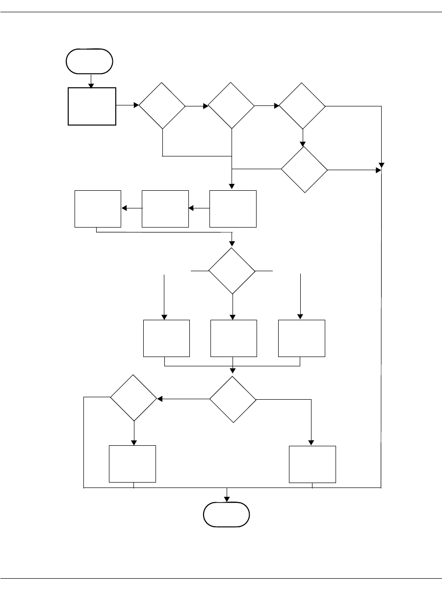
Making Call Transfers Using Bfv
November 2009 178
Figure 10. High-level Call Transfer using Bfv
BfvLineTransfer
BfvLineTransfer-
CapabilityQuery LINE_XFER_
SINGLE LINE_XFER_
ALL
False LINE_XFER_
TWO_CHAN
False
LINE_XFER_NONE
False
True
True True
BfvCallHold
BfvCallWaitFor
Hold
BfvCallSetup
(Enquiry)
supervised Successful
Yes No
2nd Channel
Specified
False
BfvLineTransfer
Complete BfvLineTransfer
Cancel
True
End
transfer_line_
state BST_ALERTINGBST_DIAL_COMPLETE
BfvCallWaitFor
BfvCallWaitFor
Complete
BfvCallWaitFor
Alerting Complete where
CP is ring or
connected
BST_CONNECTED
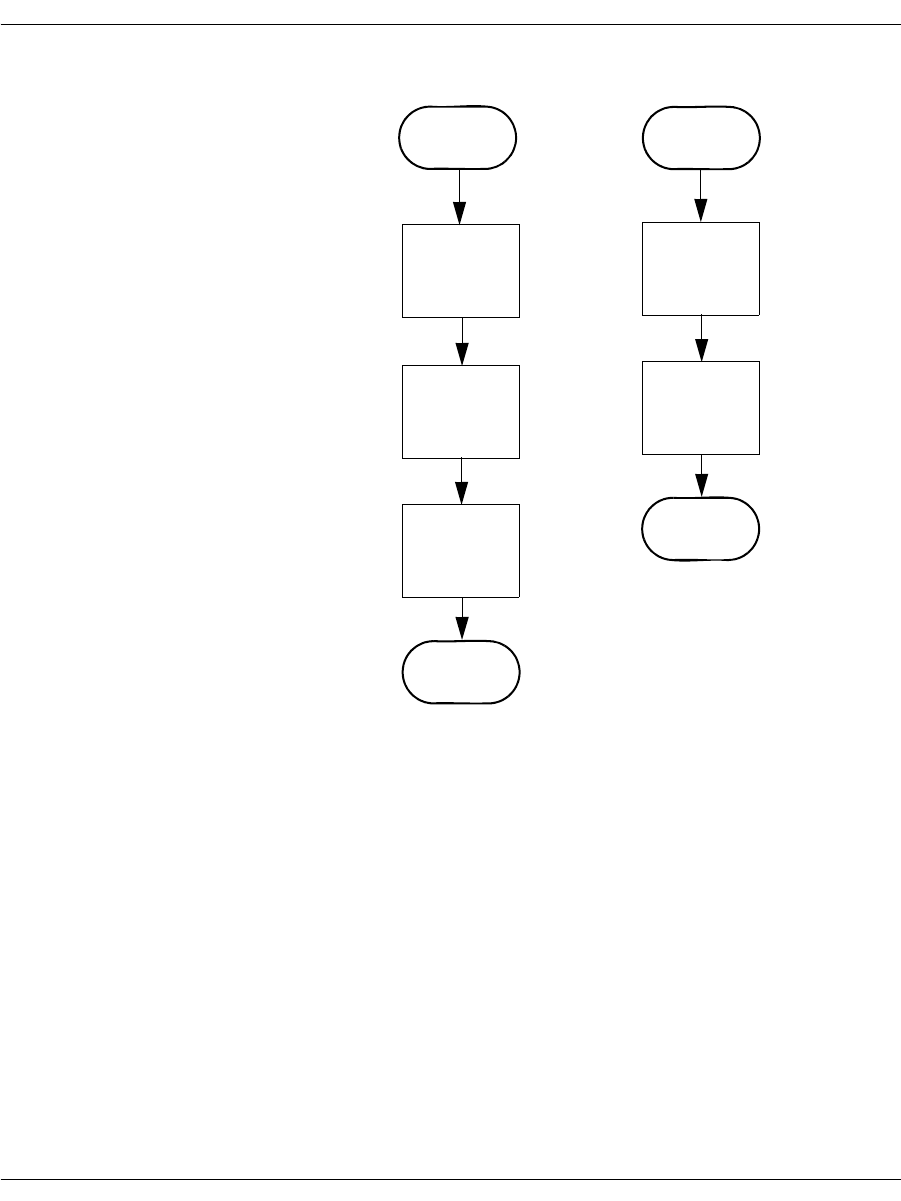
Making Call Transfers Using Bfv
November 2009 179
Figure 11. Low-level Call Transfer using Bfv
BfvLineTransfer
Complete BfvLineTransfer
Cancel
BfvCallTransfer
Complete
BfvCallWait
TransferComplete
End
BfvCallRetrieve
BfvCallWaitFor
Retrieve
End
BfvCallWaitFor
Release

Making Hookflash Transfers
November 2009 180
Making Hookflash Transfers
You can make hookflash call transfers using either the Bfv- level
API or BSMI-level API. There are two types of hookflash transfers:
Analog loop start signaling
Transfers using loop start signaling commonly use hookflash.
Hookflash allows for both blind and attended transfers using the
same channel. In a blind transfer, the application drops out of the
call before the transfer completes. In an attended transfer, the
application waits until the call is successfully connected to a new
number before completing the transfer.
T1 Robbed Bit signaling
T1 Robbed Bit hookflash transfers use E&M signaling to generate
a hookflash (wink) and initiate dial tone recall to transfer a call
using a single channel.
Using Bfv Applications
To configure using the Dialogic® Brooktrout® Configuration Tool
(Windows® only):
Set each port’s Protocol Options to T1 Robbed Bit or Analog.
Set the Flash Hook Duration between 1 - 500. These are 10ms
units.
Set the Protocol File to the following location for T1 RBS:
C:\Brooktrout\Boston\config\winkstart.lec
and for Analog, the protocol file is:
C:\Brooktrout\Boston\config\analog_loopstart_us.lec
Set the Transfer Variant to Hookflash.
Set the country_code in BTCall Parameters to 0010 (US).
Country codes are listed in:
C:\Brooktrout\Boston\bfv.api\inc\ccode.h
Note: You must be in Advanced Mode in the Brooktrout Configuration
Tool to configure BTCall Parameters.

Making Hookflash Transfers
November 2009 181
To configure using configuration files:
Set the port configuration for T1 RBS using the callctrl.cfg
configuration file:
port_config=t1_robbed_bit
or for Analog, set:
port_config=analog
Set the protocol file for T1 Robbed Bit using the callctrl.cfg
configuration file:
protocol_file=C:\Brooktrout\Boston\config\winkstart.lec
and for Analog, the protocol file is:
protocol_file=C:\Brooktrout\Boston\config\analog_loopstart_us.lec
Set the transfer_variant using the callctrl.cfg configuration
file:
transfer_variant=hookflash
The flash duration is set:
flash_hook_duration=50
Set the country code using the btcall.cfg configuration file:
country_code 0010
Country codes are listed in:
C:\Brooktrout\Boston\bfv.api\inc\ccode.h
Hookflash transfer is the only analog explicit call transfer method.
Using BSMI Applications
In T1 and analog BSMI applications, use L4L3mTX_HOOKFLASH
to set the duration of the hookflash signal. The field to set the signal
is:
L4_to_L3_struct.data.signal_duration_data = 0;
The duration of the hookflash signal is in milliseconds. The default
value is 0, which is equal to 500ms in duration. The maximum
setting is 64k.
For more information on the Brooktrout Configuration Tool, refer to the
chapter on using the configuration tool in the installation and
configuration guide that came with your software.

Making Two B-Channel Transfers
November 2009 182
Making Two B-Channel Transfers
When making a two B-channel transfer, the central office connects
two outside calls through the central office, freeing the B-channels to
take more calls. You can only transfer calls using two B-channels on
T1 ISDN PRI configurations.
Bfv maintains a maximum of two calls per B-channel. Of these two
calls, only one call is on hold at a time. Bfv provides a hold function
using BfvCallHold in your application:
BfvCallHold(lp, &args);
See page 210 for more information about putting a call on hold using
BSMI.
To configure using the Brooktrout Configuration Tool (Windows® only):
Set each port’s Protocol Options to T1 ISDN.
Set your network’s Protocol, such as AT&T PUB 41449.
Set your network’s Switch Type, such as AT&T #4 ESS.
Set the Transfer Variant to Two B-Channel.
Set the country_code in BTCall Parameters to 0010 (US).
Country codes are listed in:
C:\Brooktrout\Boston\bfv.api\inc\ccode.h
Note: You must be in Advanced Mode in the Brooktrout Configuration
Tool to configure BTCall Parameters.
To configure each port using configuration files:
Set the port configuration using the callctrl.cfg configuration file:
port_config=t1_isdn
Set the protocol using the callctrl.cfg configuration file:
protocol=att
Set the transfer_variant using the callctrl.cfg configuration
file, set:
transfer_variant=tbct
Set the country code using the btcall.cfg configuration file:
country_code 0010
Country codes are listed in:
C:\Brooktrout\Boston\bfv.api\inc\ccode.h

Making Two B-Channel Transfers
November 2009 183
For more information on the BfvCallHold function, refer to
Volume 2, Bfv API Reference Manual. For more information on the
Brooktrout Configuration Tool, refer to the chapter on using the
configuration tool in the installation and configuration guide that
came with your software.

Making Call Transfers Using QSIG
November 2009 184
Making Call Transfers Using QSIG
ISDN QSIG
QSIG is an ISO standard that defines the ISDN signaling and
control methods used to link PBXs in private ISDN networks. The
standard extends the “Q” point in the ISDN logical reference model,
which was established by the ITU-T in its Q.93x series of
recommendations that defined the basic functions of ISDN switching
systems.
QSIG is an ISDN based protocol for signaling between nodes of a
Private Integrated Services Network (PISN). In particular, QSIG
allows compatibility among products in a multi-vendor environment.
QSIG is only specified for the ISDN Interface Type Point-to-Point,
that is you cannot configure or use this protocol in conjunction with a
Point-to-Multi-Point interface.
Supplementary Services Support
QSIG supports the following supplementary services:
Calling Line Identification Presentation (Caller ID)
Calling Line Identification Restriction
Advice of Charge
Call Diversion (Unconditional, Busy and Not Responding)
Call Transfer
Name Identification
This service uses the same caller ID functions that are used with
other protocols: BfvLineWaitForCall and BfvCallWaitForSetup.
Calling Line Identification
Restriction Uses the BfvCallSetup function which allows the Bfv application to
set call presentation and screening on a per call basis.
Advice of Charge (AOC) Supplementary service enables a user to receive information on the
recorded charges for a call when the call is terminated.

Making Call Transfers Using QSIG
November 2009 185
Call Diversion Call Diversion (Unconditional, Busy and Not Responding) contains
three scenarios:
Originating - the board places a call and the far end attempts to
divert the call to a different destination. You can set Originating
to enable or disable through the call configuration file using
enable_call_diversion flag.
Served - the board receives an incoming call and attempts to
divert it. This service requires new Bfv API calls to initiate and
wait for the diversion to complete. However, it is possible for a
call to fail to divert. You use BfvCallDivert,
BFfvCallWaitForDivert, and BfvLineDivert. Once the call
is diverted, it is terminated. The application uses
BfvLineTerminteCall after a successful call diversion to make
sure that the call has been released completely.
Diverted To - the board receives an incoming call that is diverted
by another party. This service uses call_res.redir_number
and call_res.redir_reason that is returned by the
BfvLineWaitForCall or BfvCallWaitForSetup which notifies
the Bfv application that the incoming call is being diverted from
another party. As a result, the phone number of the device that
diverts the call and the reason for the diversion is provided. The
Bfv application has the option to refuse the diverted call through
BfvCallReject followed by BfvCallWaitForRelease.
Note: You must set the QSIG control parameter, disable_alerting
to On in order for the call to be rejected and retained by the
party attempting to divert the call. If this parameter is not set
to On, then the incoming call is terminated.
You can manually send an alerting message through
BfvCallSendAlerting and is used when alerting is disabled in
the call control configuration file and when the application wants
to send an alerting message to the remote end rather than answer
the call.
Call Transfer QSIG supports two B-channel transfer. Both channels must support
the TBCT capability. This is accomplished through the
BfvLineTransferCapabilityQuery. However you must connect
the 2-B channels so that both parties can communicate while the
transfer occurs. The application then uses BfvCallSwitchConnect
function to connect both B-channels. For further details, see
Volume 2, Bfv-Level Call Control and Call Switching, Bfv Reference
Manual.

Making Call Transfers Using QSIG
November 2009 186
Name Identification This feature allows the Bfv API to see the text name of the user
similar to Caller ID on an analog phone line. Therefore, if the
network provides the calling party, the calling party’s name is
reported through BfvLineWaitForCall/BfvCallWaitForSetup
functions located in the res.calling_party_subaddress field of the
args structures.
Table 7 lists the Bfv APIs that are associated with QSIG and are
documented in detail in Volume 2, Bfv-Level Call Control and Call
Switching, Bfv Reference Manual.
* Supported only on the QSIG protocol.
For detailed information concerning the Bfv API QSIG call control
configuration functions and data structures, see Volume 2, Bfv-Level
Call Control and Call Switching, Bfv Reference Manual.
Table 7. Bfv APIs Associated with QSIG
BfvLineWaitforCall
BfvCallWaitForSetup
BfvCallTransferCapabilityQuery
BfvCallDivert*
BfvCallWaitForDivert*
BfvCallSendAlerting*
BfvLineDivert*

Making Call Transfers Using Active Redirection (Japan)
November 2009 187
Making Call Transfers Using Active Redirection
(Japan)
To transfer calls in Japan, use Active Redirection, a call transfer
method that uses the central office or a PBX to transfer calls. Active
redirecting is only available for T1 ISDN PRI and ISDN BRI.
To configure using the Brooktrout Configuration Tool (Windows® only):
Set port’s Protocol Options to T1 ISDN or BRI.
Set the network Protocol to JATE (Japan) INS-1500.
Set the network Switch Type to Japan.
Set the Transfer Variant to Jate ISDN.
Set the country_code in BTCall Parameters to 0810.
A list of country codes is in:
C:\Brooktrout\Boston\bfv.api\inc\ccode.h
Note: You must be in Advanced Mode in the Brooktrout Configuration
Tool to configure BTCall Parameters.
To configure using configuration files:
Set the port configuration using the callctrl.cfg configuration file:
port_config=t1_isdn
Set the protocol using the callctrl.cfg configuration file:
protocol=ntt
Set the switch type using the callctrl.cfg configuration file:
switch_type=ntt
Set the transfer_variant using the callctrl.cfg configuration
file:
transfer_Variant=ntt
For ISDN BRI with point-to-multipoint configuration, set:
transfer_Variant=ntt_mp
Set the country code using the btcall.cfg configuration file:
country_code = 0810(Japan).
For more information on the Brooktrout Configuration Tool, refer to the
chapter on using the configuration tool in the installation and
configuration guide that came with your software.

Making Explicit Call Transfers (ECT) With E1 ISDN and BRI
November 2009 188
Making Explicit Call Transfers (ECT)
With E1 ISDN and BRI
Explicit call transfer (ECT) with E1 ISDN transfers calls using
either a single B-channel or two B-channels using switch resources
in the central office or PBX. Explicit call transfer is only used with
the Bfv API, and is available on ISDN PRI (E1) and ISDN BRI.
To configure using the Brooktrout Configuration Tool (Windows® only):
Set each port’s Protocol Options to E1 ISDN or BRI.
Set your network’s Protocol to the appropriate protocol type, such
as EURO.
Set your network’s Switch Type to the appropriate switch type, set
to Unknown/ITU conformant.
Set the Transfer Variant to Explicit Call Transfer.
Set the country_code in BTCall Parameters, leave as the default
0010.
Note: You must be in Advanced Mode in the Brooktrout Configuration
Tool to configure BTCall Parameters.
To configure using configuration files:
Set the port configuration using the callctrl.cfg configuration file:
port_config=E1_ISDN
Set the protocol using the callctrl.cfg configuration file:
protocol=EURO
Set the switch type using the callctrl.cfg configuration file, such
as:
switch_type=unknown

Making Explicit Call Transfers (ECT) With E1 ISDN and BRI
November 2009 189
Set the transfer_variant using the callctrl.cfg configuration
file:
transfer_Variant=etsi_exp_link
for explicit link transfer. You can also choose an implicit link by
setting:
transfer_Variant=etsi_imp_link
Set the country code using the btcall.cfg configuration file, leave
as default:
country_code = 0010.
Country codes are listed in:
C:\Brooktrout\Boston\bfv.api\inc\ccode.h
Your application should support the European Telecommunication
Standards Institute (ETSI) recommendations for Explicit Call
Transfer. Call hold should also be implemented in the application
using BfvCallHold, based upon recommendations from ETSI.
For more information on BfvCallHold, refer to the Volume 2,
Bfv API Reference Manual. For more information on the Brooktrout
Configuration Tool, refer to the chapter on using the configuration tool
in the installation and configuration guide that came with your
software.

Making Two-Channel Call Transfers (Tromboning)
November 2009 190
Making Two-Channel Call Transfers (Tromboning)
This section provides information about creating a two-channel call
transfer (trombone call transfer).
A two-channel call transfer occurs when an application connects a
calling party to a called party with a full duplex connection, while
maintaining control of both calls. For some applications, this method
of transfer provides redundancy with no added benefits. However,
for applications that require monitoring or functionality not provided
by the caller and called resources, this method supports the
additional functionality. The Bfv API manages two-channel transfer
by transferring an existing call to another channel and becoming a
link in the network rather than an end-point for either channel.
An application might use this method of call transfer to monitor or
record the calls or to perform an activity such as speech recognition
during the call.
When configuring your module for two channel call transfer activities,
establish a maximum of 5 channels per DSP configuration.
The section contains the following:
Setting up the Two-Channel Call Transfer
Actions During a Two-Channel Call Transfer
Terminating the Two-Channel Call Transfer
Disconnecting Resources

Making Two-Channel Call Transfers (Tromboning)
November 2009 191
Setting up the Two-Channel Call Transfer
In the typical two way call transfer application, the application
detects an incoming call and answers the call. The application then
performs voice playback and voice recognition functions as needed,
responding to the caller's spoken utterances. For example, a caller
might speak someone's name and the application then accesses that
person's phone number. The application then makes an outbound
call on another channel by dialing that person's phone number.
When the person answers the call, the application connects the two
parties together and monitors both resources to provide additional
functionality.
Connecting Resources
To create the two-channel call transfer and perform the required
additional functionality, the application must connect various
hardware resources. These resources are network timeslots for a
T1/E1 phone line or channels. Each resource has an input slot and
an output slot. When connecting two resources together, one
resource must be defined as the source and the other resource
defined as the destination. The application should define the
connection type between the two resources as “transmit” because the
Brooktrout hardware maintains connections as transmits.
To understand the basic connections that exist between a channel
and a network timeslot, see Figure 12. These connections are defined
in a Brooktrout configuration file called callctrl.cfg. The connection
lines represent both signaling and voice data. When making a
two-channel call transfer, the application should modify only the
voice data connections.

Making Two-Channel Call Transfers (Tromboning)
November 2009 192
Figure 12. Connections for Standard (non-transfer) Operation
In Figure 12 the output slot of Channel_0 transmits to the input slot
of network timeslot 0, while the output slot of network timeslot 0
transmits to the input slot of Channel_0. The connections between
Channel 0 and network timeslot 0 create a full duplex voice session.
Also observe that the output slot of Channel 1 transmits to the input
slot of network timeslot 1, while the output slot of network timeslot 1
transmits to the input slot of Channel 1.
Use the following Bfv functions to access or change the connection
information that is maintained on the Brooktrout hardware:
BfvCallSWClearConns()
Clears resource connection
BfvCallSWConnect()
Connects or disconnects resources
BfvCallSWGetConns()
Queries for connection information
BfvCallSWGetInfo()
Provides information about the two-channel call
Refer to Volume 1 of the Bfv API Reference Manual for further
information on these functions.
The BfvCallSWConnect() and BfvCallSWGetConns() functions
are the most important when setting up a two-channel call transfer.
Before creating a two-channel call transfer, call the
BfvCallSWGetConns() function to get the current connection data
that is stored on the module. Store this information in a local
Channel 0
In Ref In
Out
Channel 1
In Ref In
Out
TSlot 1
Out In
TSlot 0
Out In
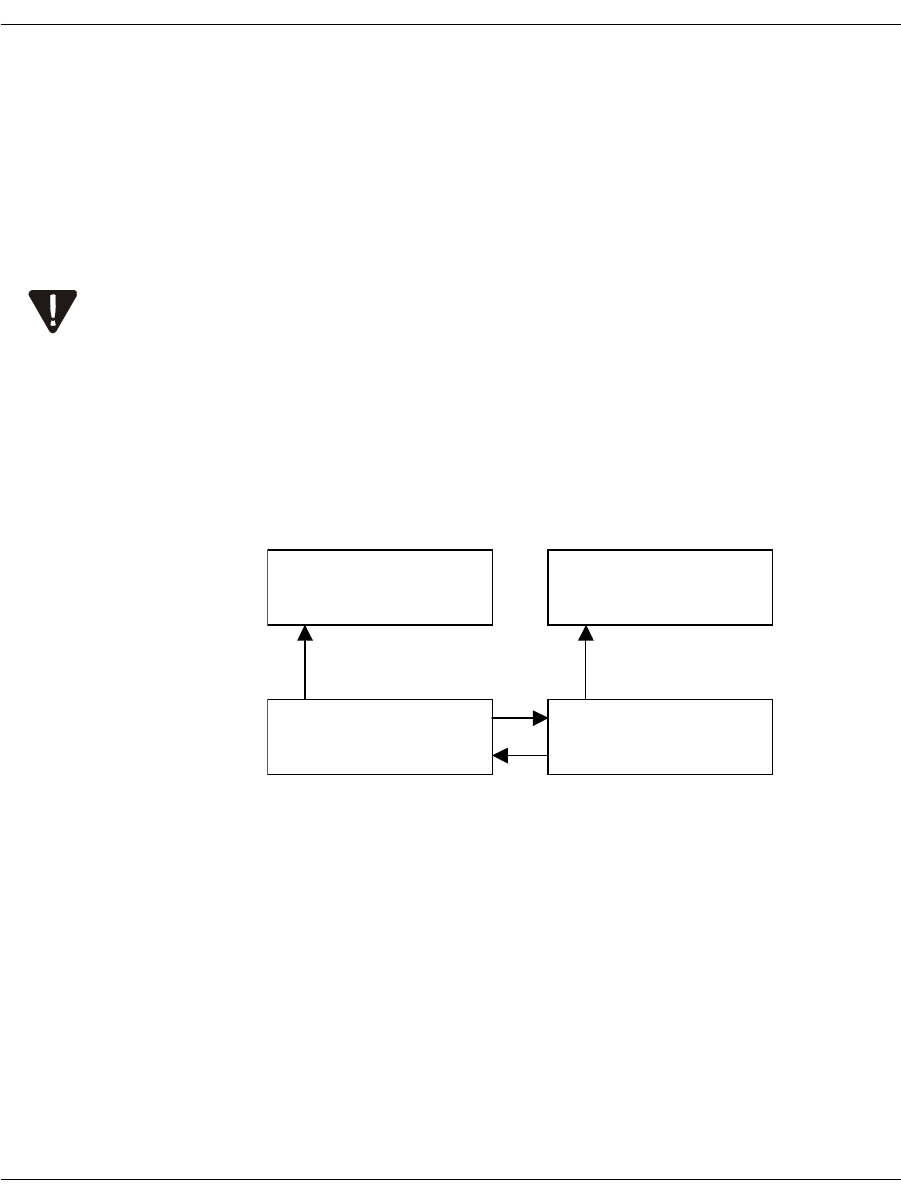
Making Two-Channel Call Transfers (Tromboning)
November 2009 193
variable where it is easily accessed and restored when disconnecting
the two-channel call transfer (see Terminating the Two-Channel Call
Transfer on page 199).
When connecting and disconnecting resources, the application
should primarily use the BfvCallSWConnect() function. The
application must provide all connections with a source and
destination resource. The following rule is very important when
connecting resources together:
A source resource can have many destination resources, but a
destination resource must have only one source resource.
Before setting up the two-channel call transfer, remove any existing
connections that conflict with the transfer connections.
For a model of a two-channel call transfer, see Figure 13. The OUT
label represents the source of the connection and the IN label
represents the destination of the connection.
Figure 13. Connections for a Two-Channel Call Transfer
The application removed the connection from the output of
Channel 0 to the input of network timeslot 0 and the connection
from the output of Channel 1 to the input of network timeslot 1. If
these connections were not removed from Figure 12 on page 192,
then Channel 0 and network timeslot 1 would both be attempting to
transmit to the input of network timeslot 0, violating the above rule.
Channel 1
In Out
Channel 0
In Out
TSlot 1
Out In
TSlot 0
Out In
Person B Person A

Making Two-Channel Call Transfers (Tromboning)
November 2009 194
The application created a new connection from the output of network
timeslot 0 to the input of network timeslot 1 and another new
connection from the output of network timeslot 1 to the input of
network timeslot 0 (see Figure 13 on page 193).
Using this model, Channel 0 can record the data that is being
transmitted from the network timeslot 0 and Channel 1 can record
the data that is being transmitted from network timeslot 1.
Because of firmware requirements, when disconnecting resources, you
have to invert the source and destination resources. For example, if you
made a transmit connection from the output slot of Channel 0 to the input
slot of network timeslot 0, where Channel 0 is the source, then you must
disconnect from the input slot of network timeslot 0 to the output slot of
Channel 0.
Actions During a Two-Channel Call Transfer
After the application establishes a two-channel call transfer, it can
then perform voice playback and voice recognition. In addition to
these voice actions, the application must provide secondary
functionality. For example, when performing voice recognition
during a two-channel call transfer, the application must configure
echo cancellation in the channel correctly. Also, when performing
voice playback to a caller, the application must place the other caller
on hold to avoid providing the original caller with two source inputs.
Performing Echo Cancellation
When a caller sends voice data over the telephone network, the
network reflects some of that data back as input data. The reflected
data is then mixed in with valid input voice data from the remote
end. The channel that is connected to the telephone network must be
able to remove the reflected data from the valid input data. This
technique is called echo cancellation.
When a channel performs echo cancellation, it analyzes the voice
data that is being sent out into the telephone network. When this
voice data reappears as input voice data (the echo), the channel
removes the data from the input data stream. What is left is the
actual voice data from the remote end.

Making Two-Channel Call Transfers (Tromboning)
November 2009 195
When the application creates a two-channel call transfer, the two
callers become sources of the reflected data. The application must
configure the echo cancellation portion of the channel resource to
remove repeated input from two sources by using its reference signal
slot (the channel’s reference number is 1). The application must also
call the BfvSpeechEchoCancelControl() function to configure the
channel to accept an input reference signal on slot #1.
For example, your application could create a connection from the
output slot of Network resource 1 to the reference input slot of
Channel 0 by calling the BfvSpeechEchoCancelControl() and
BfvCallSWConnect() functions with the following arguments:
BT_ZERO(speech_args);
/* Configure channel to get its input reference signal from slot #1. */
Speech_args.echoc_op = ECHOC_OP_ALT_INPUT_ENABLE;
BfvSpeechEchoCancelControl (lp, &speech_args);
BT_ZERO(args);
args.conn_mode = CALL_SW_TRANSMIT_ONLY_DEF;
args.src_port_class = CALL_SW_PORT_NETWORK_DEF;
args.src_port_unit = 0;
args.src_stream = 0;
args.src_slot = 1; /* Network Timeslot */
args.dest_port_class = CALL_SW_PORT_CHANNEL_DEF;
args.dest_port_unit = 2; /* Logical DSP Channel Number */
args.dest_stream = 0;
args.dest_slot = 1; /* Reference Slot */
BfvCallSWConnect (lp, &args);
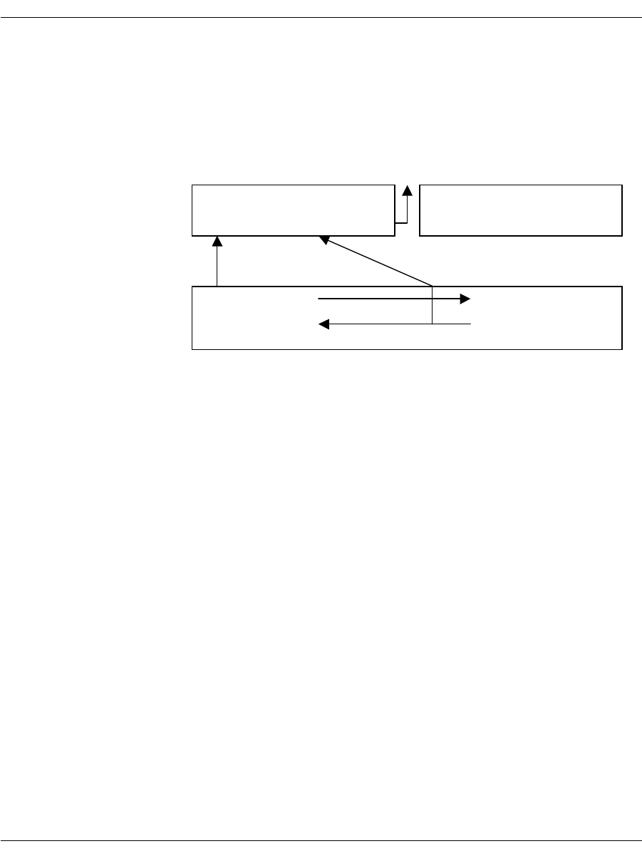
Making Two-Channel Call Transfers (Tromboning)
November 2009 196
Figure 14 on page 196 shows the connections required to configure
the echo canceller on a channel during a two-channel call transfer
while recording from person A. The application sends the final echo
cancelled data up to the host for recording.
Figure 14. Required Connections for Echo Cancellation
Channel 1
In Ref_In
Out
In
TSlot 0
Person A
Host
Out Ref_Out
Channel 1
In Ref_InOut Ref_Out
In
Out
TSlot 1
Person B
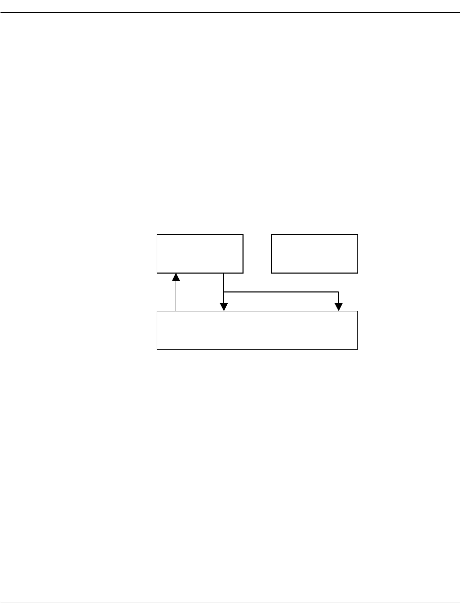
Making Two-Channel Call Transfers (Tromboning)
November 2009 197
Playing Back Voice Recordings
Voice playback during a two-channel call transfer can take one of
two forms.
The voice application plays voice data to both callers.
In this example, the channel playing the voice data is the source
resource and the network timeslots are the destination resources.
Before voice playback begins, to avoid providing the destinations
with more than one source, the application must disconnect the
full duplex connection between the network timeslots. This
ensures that the two network timeslots can't transmit data to
each other. After voice playback has ended, the application can
re-establish the full duplex connection between the network
timeslots. Refer to Figure 15 for this situation.
Figure 15. Playing Voice Data To Two-Channels
The voice application plays data to one caller while placing the
other caller on hold.
In this example, the channel transmits voice data to just one
network timeslot. The application must place the other network
timeslot on hold (disconnecting it from the full duplex connection
using the BfvCallSWConnect() function) to avoid providing the
network timeslot that is receiving the playback data with a
second source input.
When your application terminates the full duplex connection to
the network timeslot that is not receiving playback data, the
caller might hear noise. To prevent this, connect the input slot of
the network timeslot to the output slot of an idle channel (an idle
Channel 0
In Out
TSlot 1
Person B
Channel 1
In Out
Out In
TSlot 0
Person A
Out In
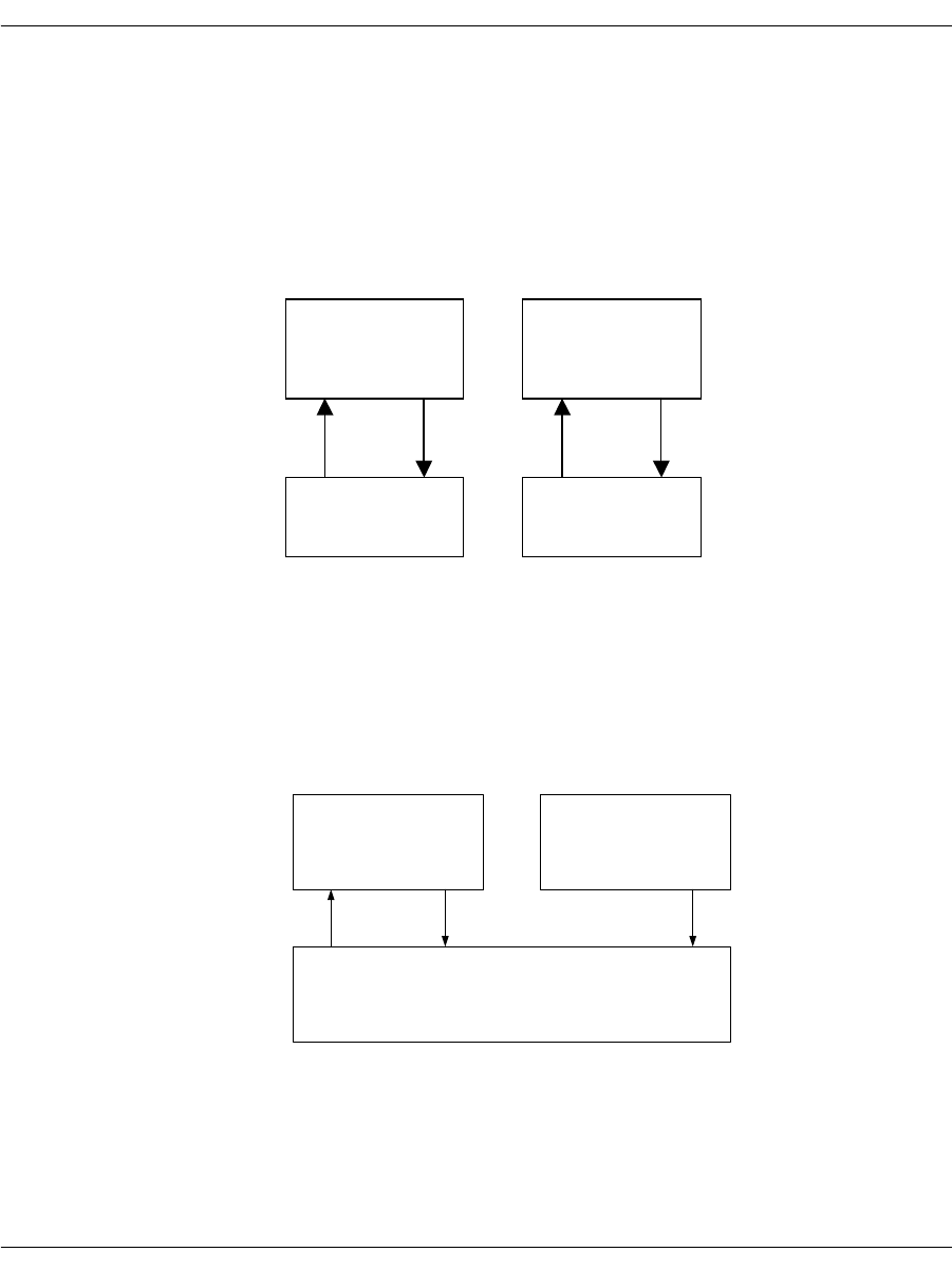
Making Two-Channel Call Transfers (Tromboning)
November 2009 198
channel provides silence generation on its output). After playback
is completed, the application can re-establish the full duplex
connection.
The following series of illustrations demonstrate the changes.
In Figure 16, there is a full duplex connection between channel 0 and
TSlot 0, and another full duplex connection between channel 1 and
TSlot 1.
Figure 16. Standard Full Duplex Connections
In Figure 17, there is a full duplex connection between TSlot 0 and
TSlot 1. Channel 0 is recording the caller on TSlot 0. The application
connected TSlot 1 to the reference input of channel 0 to provide echo
cancellation.
Figure 17. A Connected Two Channel Transfer.
Channel 0
In Ref In
Out
TSlot 1
Channel 1
In
Out In Out In
Ref In
Out
TSlot 0
Channel 0
In Ref In
Out
Channel 1
In Ref In
Out
TSlot 1
Out In
TSlot 0
Out In
(Silence)
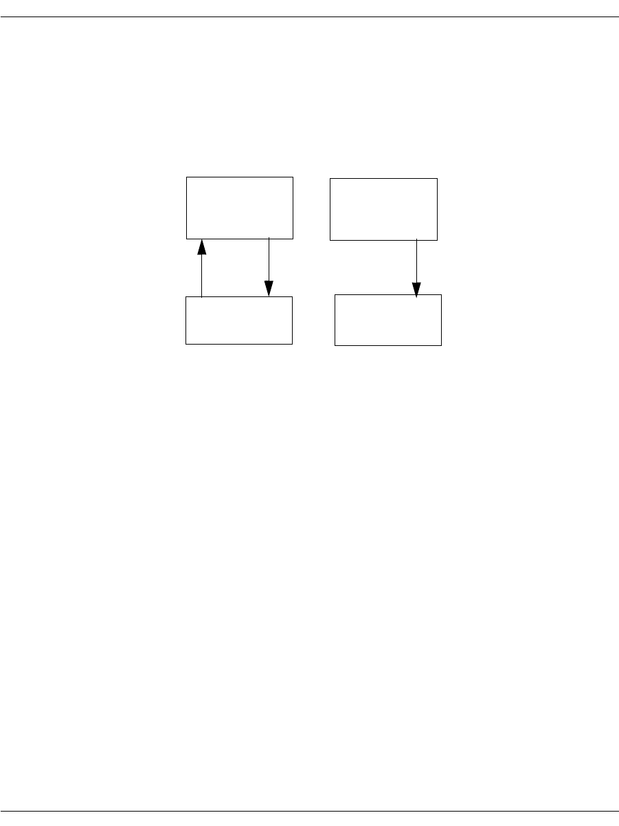
Making Two-Channel Call Transfers (Tromboning)
November 2009 199
In Figure 18, the application places the caller on TSlot 1 on hold and
generates silence from channel 1 to the caller. There is a full duplex
connection between channel 0 and TSlot 0. Channel 0 is playing a
voice prompt to the caller on TSlot 0 while recording.
To take the caller on TSlot 1 off hold, re-establish the connections as
they were in Figure 17.
Figure 18. Playing the Voice Prompt and Generating Silence
Terminating the Two-Channel Call Transfer
Your application terminates a two-channel call transfer by deleting
the transfer connections and restoring the original connections that
were present before the two-channel call transfer was created. After
terminating a two-channel call transfer, the application remains
connected to the original caller (person A). There are three situations
that cause a two-channel call transfer to be terminated:
If the application detects a recognition signal that indicates
terminating the two-channel call.
The application hangs up on the called party (person B) while
staying connected to the original calling party (person A).
The called party hangs up.
The application alerts the original caller of the remote hang up,
then disconnects the called party while staying connected to the
original calling party.
The original calling party hangs up.
The application should then disconnect the entire two-channel
call transfer and wait for another call.
Channel 0
In
Out
Out Out InIn
TSlot 0 TSlot 1
Ref In
Channel 1
In
Out
Ref In
(Silence)

Making Two-Channel Call Transfers (Tromboning)
November 2009 200
Disconnecting Resources
When disconnecting resources, invert the source and destination
resources so that the firmware responds appropriately.
Due to firmware requirements, when disconnecting resources, invert the
source and destination resources. For example, if you made a transmit
connection from the output slot of Channel 0 to the input slot of network
timeslot 0, where Channel 0 is the source, then you must disconnect
from the input slot of network timeslot 0 to the output slot of Channel 0.
Use the BfvCallSWConnect() function to disconnect connections.
For example, if you made a transmit connection from the output of
Channel 0 to the input of network timeslot 0, where Channel 0 is the
source, then you must disconnect from the input of network
timeslot 0 to the output of Channel 0. The following source code
shows this:
BT_ZERO(args);
args.conn_mode = CALL_SW_DISCONNECT_DEF;
args.src_port_class = CALL_SW_PORT_NETWORK_DEF;
args.src_port_unit = 0;
args.src_stream = 0;
args.src_slot = 0; /* Network Timeslot */
args.dest_port_class = CALL_SW_PORT_CHANNEL_DEF;
args.dest_port_unit = 2; /* Logical DSP Channel Number */
args.dest_stream = 0;
args.dest_slot = 0;
BfvCallSWConnect (lp, &args);
If the application stored the original connection information in a
local variable before creating the two-channel call transfer, restore
the original connection by calling the BfvCallSWConnect function
and referencing the local variable.

Making Two-Channel Call Transfers (Tromboning)
November 2009 201
If the application configured the echo canceller in the channel to get
an input reference signal from slot #1, then the application must
remove this configuration to return the echo canceller to its default
behavior. To do this the application must call the
BfvSpeechEchoCancelControl() function (See Volume 3 of the
Bfv API Reference Manual). For example:
BT_ZERO(speech_args);
speech_args.echoc_op = ECHOC_OP_ALT_INPUT_DISABLE;
BfvSpeechEchoCancelControl (lp, &speech_args);
Calling the BfvLineReset() function on a channel also returns the
echo canceller to its default behavior.

Transferring Calls Using Release Link Trunk Transfer
November 2009 202
Transferring Calls Using Release Link Trunk Transfer
Release Link Trunk is an explicit call transfer method for Nortel
DMS-250 switches and is only available for Nortel switches.
The host application initiates the Release Link Trunk (RLT) action,
but the call transfer is completed within the public switch network.
Calls come into the network on two B-channels. Each channel
maintains its call and both channels are busy. When the call
finishes, the B-channels are torn down.
Using Bfv Applications
Set Release Link Trunk in your Bfv application using the
BfvLineTransfer argument:
args.lp_second_Channel
A zero (0) value transfers calls over a single channel, such as an
analog line.
To configure using the Brooktrout Configuration Tool (Windows® only):
Set each port’s Protocol Options to T1 ISDN.
Set the Protocol to Northern Telecom NIS A211-1.
Set the Switch Type to Northern Telecom DMS-250.
Set the Transfer Variant to Release Link Trunk (DMS-100 or
DMS-250).
Set the country_code in BTCall Parameters to 0010 (US).
Country codes are listed in:
C:\Brooktrout\Boston\bfv.api\inc\ccode.h
Note: You must be in Advanced Mode in the Brooktrout Configuration
Tool to configure BTCall Parameters.
To configure using configuration files:
Set the port configuration using the callctrl.cfg configuration file:
port_config=t1_isdn
Set the protocol using the callctrl.cfg configuration file:
protocol=nortel

Transferring Calls Using Release Link Trunk Transfer
November 2009 203
Set the switch type using the callctrl.cfg configuration file:
switch_type=nti_dms250
Set the transfer_variant using the callctrl.cfg configuration
file, set:
transfer_Variant=rlt
Set the country code using the btcall.cfg configuration file:
country_code = 0010(US).
Country codes are listed in:
C:\Brooktrout\Boston\bfv.api\inc\ccode.h
Using BSMI Applications
Call transfer RLT functionality in BSMI is set in
L4L3CALL_REQUEST:
rlt_service = 1
Note: RLT is set with any non-zero value.
The destination number is set in L4L3CALL_REQUEST:
data.call_req_data.redirect_num.num_digits = 0;
RLT functionality in BSMI requires the D-channel set in
L4L3mENABLE_PROTOCOL with:
‘switch_type’ = IISDNstDMS-250
and
‘variant’ = IISDNvarNORTEL_CUSTOM
If the switch does not support RLT, an L3L4mALERTING message
is received and the call is not transferred.
Applications with RLT release PRI-ISDN circuits after call transfer
occurs, releasing corresponding circuits. A call comes through a
B-channel, the caller requests a number and that call is transferred
from one B-channel to the other B-channel. The calls are connected
inside the public switch and remain active. The application tears
down both B-channels and releases the link.
Calls without RLT are extended and subsequently bridged to a third
party. The third party maintains the call and circuits are kept active
and in service. This ties up additional circuits on the PRI trunk.

Transferring Calls Using Release Link Trunk Transfer
November 2009 204
For more information on L4L3mENABLE_PROTOCOL and
L3L4mALERTING, please refer to Volume 5, Bfv API Reference
Manual. For more information on the Brooktrout Configuration Tool,
refer to the chapter on using the configuration tool in the installation
and configuration guide that came with your software.
Call Control Sequence Diagrams
The charts below describe call transfer n using BSMI, both with the
RLT functionality of the DMS-250, and the traditional method (for
purposes of comparison).
In both calls, the board receives an incoming call and determines
that the call needs to be rerouted to an alternate destination. In the
non-RLT call transfer configuration, the application initiates an
outbound call to the reroute destination and uses the TSI matrix to
pass incoming data from the call originator to the reroute
destination.
Non-RLT Call Transfer
Network Host
SETUP ===> L3L4mSETUP_IND (B1) The host receives the incoming call on
B-channel #1. From the
IISDN_CALLED_PARTY info, the host
determines that this call needs to be rerouted
to an alternate branch office.
===> L3L4mSET_TSI
src=IISDNtsiLINE_A+1
dst=IISDNtsiLINE_A+2
src=IISDNtsiLINE_A+2
dst=IISDNtsiLINE_A+1
The host cross-connects B1 and B2.
Map B1 to B2 on Span A.
Map B2 to B1 on Span A.
SETUP <=== L4L3mCALL_REQUEST (B2) The host initiates the outbound call on B2,
where the call transfer occurs.
ALERTING ===> L3L4mALERTING (B2) Call setup completes normally on B-channel
#2 with receipt of ALERTING and
CONNECT.
CONNECT ===> L3L4mCONNECT (B2)

Transferring Calls Using Release Link Trunk Transfer
November 2009 205
The call is transferred by the board, but it must maintain active call
setup on both B-channels for the duration of the call.
RLT Call Transfer
ALERTING <=== L4L3mALERTING (B1) Now that B-channel #2 is set up, continue
with normal call setup on B1, sending
alerting and connect.
CONNECT <=== L4L3mCONNECT (B1)
Network Host
SETUP ===> L3L4mSETUP_IND (B1) The host receives an incoming call on
B-channel #1. From the
IISDN_CALLED_PARTY info, the host
application determines this call needs to be
rerouted to an alternate branch office.
SETUP <=== L4L3mCALL_REQUEST (B2)
rtl_service = 1 The host initiates outbound call on B2,
setting the rlt_service flag to ‘1’.
ALERTING ===> L3L4mALERTING (B2)
includes 0x1c (FACILITY) IE with
call_id.
The network sends an ALERTING message
with the FACILITY info element containing
the call ID for the second link.
CONNECT ===> L3L4mCONNECT (B2)
FACILITY <=== L4L3mFACILITY_REQUEST The host initiates the transfer and release
process by sending a FACILITY message.
The call_ref and l4_ref parameters of the
initial (B1) call sends a
L4L3mFACILITY_REQUEST message,
and the application populates the
IISDN_CALL_ID field with the call_id
information retrieved from the ALERTING
message of the second call (B2).

Transferring Calls Using Release Link Trunk Transfer
November 2009 206
Once the network establishes a direct connection between the
originator of the first call and the final destination of the second call,
it sends DISCONNECT messages for both B1 and B2. The calls are
released on the board (and the board does not need to keep two
B-channels established), but the switch maintains the actual
connections between the originator and the reroute destination.
DISCONNECT=====>L3L4mDISCONNECT (B1)
DISCONNECT=====>L3L4mDISCONNECT (B2)
For more information about the messages, see Volume 5, Bfv API
Reference Manual.

Transferring Calls Using Release Link Trunk Transfer
November 2009 207
Sample Application
The following code fragments show the relevant BSMI control
messages used in RLT transfer.
/***********************************************************************/
/********** send_call_req ****/
/***********************************************************************/
void send_call_req(int spyder_chan,int bchan,unsigned char rlt)
{
L4_to_L3_struct *L4L3cntlp;
L4_to_L3_struct msg;
L4L3cntlp = &msg;
/* Populate the header stuff here */
zero_msg(L4L3cntlp);
L4L3cntlp->lapdid = spyder_chan;
L4L3cntlp->msgtype = L4L3mCALL_REQUEST;
L4L3cntlp->L4_ref = 1;
L4L3cntlp->call_ref = 0;
/* Populate the call request stuff here */
L4L3cntlp->data.call_req_data.bchannel = bchan;
L4L3cntlp->data.call_req_data.interface = 0xff;
L4L3cntlp->data.call_req_data.call_type = PRIcalltyp64K;
L4L3cntlp->data.call_req_data.rlt_service = rlt;
L4L3cntlp->data.call_req_data.called_party.num_digits = 6;
L4L3cntlp->data.call_req_data.called_party.num_type = PRInumtUNKNOWN;
L4L3cntlp->data.call_req_data.called_party.num_plan = PRInumpUNKNOWN;
L4L3cntlp->data.call_req_data.called_party.digits[0] = '6';
L4L3cntlp->data.call_req_data.called_party.digits[1] = '0';
L4L3cntlp->data.call_req_data.called_party.digits[2] = '3';
L4L3cntlp->data.call_req_data.called_party.digits[3] = '8';
L4L3cntlp->data.call_req_data.called_party.digits[4] = '9';
L4L3cntlp->data.call_req_data.called_party.digits[5] = '8';
L4L3cntlp->data.call_req_data.redirect_num.num_digits = 0;
pridrv_tx_cntl_buf( L4L3cntlp);
printf("%d: Snd L4L3mCALL_REQUEST \n", spyder_chan);
} /* end of send_call_req */

Transferring Calls Using Release Link Trunk Transfer
November 2009 208
/***********************************************************************/
/********** Send alerting ****/
/***********************************************************************/
void send_alert(int spy_chan, int call_ref)
{
L4_to_L3_struct *L4L3cntlp;
L4_to_L3_struct msg;
L4L3cntlp = &msg;
zero_msg(L4L3cntlp);
L4L3cntlp->lapdid = spy_chan;
L4L3cntlp->L4_ref = 0;
L4L3cntlp->call_ref = call_ref;
printf("%d: Snd L4L3mALERTING_REQUEST \n", spy_chan);
L4L3cntlp->msgtype = L4L3mALERTING_REQUEST;
if (spy_chan == NETWORK) /* we know the net is sending a facility */
{
L4L3cntlp->data.al_con_data.interface= 0xff;
L4L3cntlp->data.al_con_data.bchannel= g_bchan;
L4L3cntlp->data.al_con_data.ie_count = 1;
L4L3cntlp->data.al_con_data.ie.ie_id = 0x1c; /* facility */
L4L3cntlp->data.al_con_data.ie.ie_length = 0x0e;
L4L3cntlp->data.al_con_data.ie.ie_data[0] = 0x91; /*rose*/
L4L3cntlp->data.al_con_data.ie.ie_data[1] = 0xbe; /*rlt*/
L4L3cntlp->data.al_con_data.ie.ie_data[2] = 0xa2; /*RR*/
L4L3cntlp->data.al_con_data.ie.ie_data[3] = 0x09; /*length*/
L4L3cntlp->data.al_con_data.ie.ie_data[4] = 0x02; /*id tag*/
L4L3cntlp->data.al_con_data.ie.ie_data[5] = 0x01; /*id len*/
L4L3cntlp->data.al_con_data.ie.ie_data[6] = 0x01; /*inv id*/
L4L3cntlp->data.al_con_data.ie.ie_data[7] = 0x02; /*seq tag*/
L4L3cntlp->data.al_con_data.ie.ie_data[8] = 0x01; /*seq len*/
L4L3cntlp->data.al_con_data.ie.ie_data[9] = 0x01; /*op tag*/
L4L3cntlp->data.al_con_data.ie.ie_data[11] = 0x01;/*op len*/
L4L3cntlp->data.al_con_data.ie.ie_data[12] = 0x80; /*op val*/
L4L3cntlp->data.al_con_data.ie.ie_data[13] = 0; /*callid*/
L4L3cntlp->data.al_con_data.ie.ie_data[14] = 0;
}
pridrv_tx_cntl_buf( L4L3cntlp);
}

Transferring Calls Using Release Link Trunk Transfer
November 2009 209
/***********************************************************************/
/************** Send facility ****/
/***********************************************************************/
/* Send L4L3mFACILITY */
void send_facility(int spy_chan, int call_ref)
{
L4_to_L3_struct *L4L3cntlp;
L4_to_L3_struct msg;
unsigned char*ieptr;
L4L3cntlp = &msg;
zero_msg(L4L3cntlp);
L4L3cntlp->lapdid = spy_chan;
L4L3cntlp->L4_ref = 0;
L4L3cntlp->call_ref = call_ref;
L4L3cntlp->msgtype = L4L3mFACILITY_REQUEST;
printf("%d: Snd L4L3mFACILITY_REQUEST\n", spy_chan);
L4L3cntlp->data.facility_data.call_id.len = 1;
L4L3cntlp->data.facility_data.call_id.call_id[0]= 2;
pridrv_tx_cntl_buf( L4L3cntlp);
}

Placing Calls on Hold Using BSMI
November 2009 210
Placing Calls on Hold Using BSMI
When you invoke hold functions in BSMI, the host sends an
L4L3mUNIVERSAL message to the board with the
data.universal.msg_id field set to a value in Table 8, also
detailed in Example 1. The board accepts messages from either the
host (using an L4L3mUNIVERSAL message) and passes them to
the network, or takes network messages and passes them to the host
(in an L3L4mUNIVERSAL message).
Additional Informational Elements (IE) are added normally to the
application. If sending an MT_DL_HOLD_REJ or an
MT_DL_RETRIEVE_REJ message, add a CAUSE IE (see
Example 2).
L3L4mUNIVERSAL messages are received with the
data.universal.msg_id field set to a value from Table 8. If IEs
are contained within the message
(l34msg->data.universal.ie_count > 0), messages are
handled normally.
Table 8. Call Hold Values for L4L3mUNIVERSAL messages
#define MT_DL_HOLD 0x24 //ITU-T Q.932 subclass 8.1
#define MT_DL_HOLD_ACK 0x28 //ITU-T Q.932 subclass 8.1
#define MT_DL_HOLD_REJ 0x30 //ITU-T Q.932 subclass 8.1
#define MT_DL_RETRIEVE 0x31 //ITU-T Q.932 subclass 8.1
#define MT_DL_RETRIEVE_ACK 0x33 //ITU-T Q.932 subclass 8.1, must contain a
CAUSE IE
#define MT_DL_RETRIEVE_REJ 0x37 //ITU-T Q.932 subclass 8.1, must contain a
CAUSE IE
#define MT_DL_STATUS 0x7D //ITU-T Q.931 subclass 84.4, not used in
L4L3mUNIVERSAL messages

Placing Calls on Hold Using BSMI
November 2009 211
Example 1
memset(&l43msg,0,sizeof(L4_to_L3_struct));
l43msg->msgtype = L4L3mUNIVERSAL;
l43msg->data.universal.msg_id = MT_DL_RETRIEVE;
Example 2
#define IEID_CAUSE 0x08 //CAUSE IE ID code
#define EXTENSION_BIT 0x80 //extension bit for an octet
memset(&l43msg,0,sizeof(L4_to_L3_struct));
l43msg->msgtype = L4L3mUNIVERSAL;
l43msg->data.universal.msg_id = MT_DL_RETRIEVE_REJ;
l43msg->data.universal.ie_count = 1; //must equal all IEs
l43msg->data.universal.ie.ie_id = IEID_CAUSE;
l43msg->data.universal.ie.ie_length = 2;
l43msg->data.universal.ie.ie_data[0] = EXTENSION_BIT | Coding_standard |
Location; //where Coding_standard and Location are from ITU-T Q.850
// subclause 2.2.2 and 2.2.3 respectively
l43msg->data.universal.ie.ie_data[1] = EXTENSION_BIT | Cause ; //where Cause
is from ITU-T Q.850 subclause 2.2.5
For more information on L4L3mUNIVERSAL and
L3L4mUNIVERSAL, see Volume 5, Bfv API Reference Manual.

Placing Calls on Hold Using BSMI
November 2009 212

November 2009 214
6 - Managing Fax and Voice over IP
Sessions
This chapter describes how to develop applications that use the
internet for fax and voice media.
To establish Internet Protocol (IP) sessions, Dialogic uses the
Session Initiation Protocol (SIP) and the H.323 Protocol.
To manage fax and voice media, Dialogic uses T.38 and RTP
protocols. This chapter has the following sections:
Managing Calls Using IP Telephony
Failover Based on Telephony Cause Codes
Configuring T.38, RTP and IP Call Control Activities
Troubleshooting
Understanding the SIP Protocol
Using Third Party IP Stacks

Managing Calls Using IP Telephony
November 2009 215
Managing Calls Using IP Telephony
The Bfv API supports fax functionality over IP networks using the
Session Initiation Protocol (SIP) and the H.323 protocol as well as
the PSTN network (using ISDN, RBS, R2 MFC, and analog loop
start call control protocols) through a common and consistent
programming interface. This flexibility helps you to develop fax
applications that can place and receive calls over traditional PSTN
and IP transports using modules or the SR140.
Note: Be aware of the following regarding IP calls:
H.323 (fast or slow start) or SIP is used to establish calls over the
IP network.
The SR140 software supports T.38, G.711 fax pass-through, and
audio calls.
The TR1034 board module supports T.38, G.711 fax pass-
through, and audio calls on some models
SR140 and TR1034 both use RTP sessions before the T.38
transmission is established. The RTP contains the CED or CNG
tones used to establish a fax call.
Only G.711 DTMF generation and detection in the RTP stream
is supported on the SR140 and TR1034 platforms.
All channels on a given module must be configured for IP call control
or for PSTN call control. Dialogic does not support combined modes
of call control on a given module. Multiple modules within a system
can be configured to support several modes of call control, each
module being configured to support only one mode.
For proper operation, the SR140 or the TR1034 Ethernet interface
(the one used for IP call control) should be wired to a common hub or
switch. Figure 19 on page 216 shows a typical network wiring
configuration.
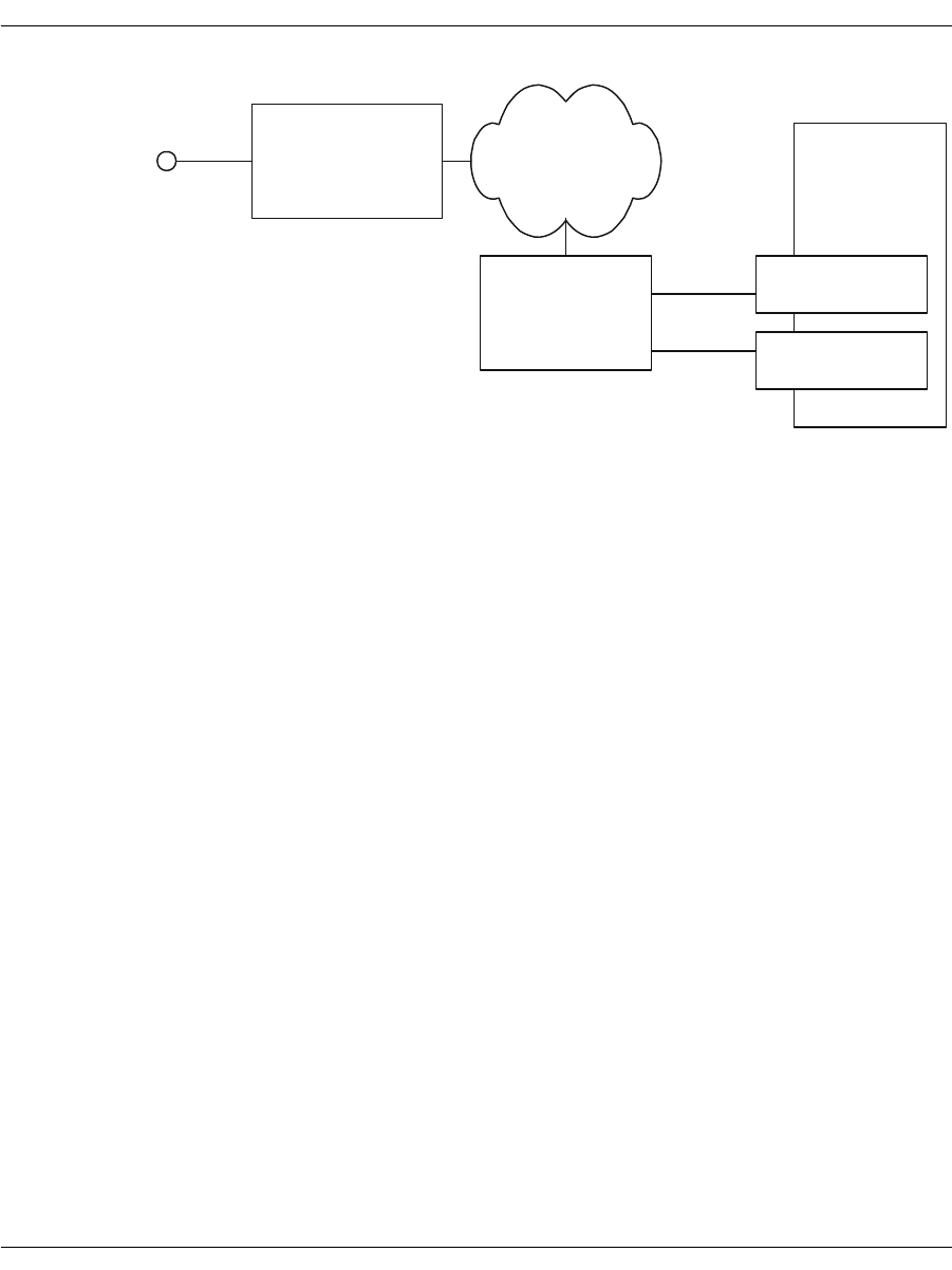
Managing Calls Using IP Telephony
November 2009 216
Figure 19. SIP Configuration Model
With dual-purpose modules in place, end-users can choose between
PSTN or IP mode. Your applications can determine whether the
module supports the IP or PSTN mode either at runtime or
installation.
Adding IP Call Control using the Bfv API
Because the Dialogic® Brooktrout® Bfv API uniformly supports a
wide set of transports including IP, you can use the same
applications to manage calls over IP as when using the PSTN.You
can configure IP call control using the Dialogic® Brooktrout®
Configuration Tool (a GUI product) or by setting values in call
control configuration files.
LAN
Host NIC (SIP)
TR1034 (T.38)
Host
(with fax
application)
Ethernet
Ethernet
Gateway
PSTN to SIP/T.38
T1/E1
Ethernet
Switch or Hub
(IP)

Managing Calls Using IP Telephony
November 2009 217
Outgoing IP Calls
Your application manages outgoing calls if it performs the following:
Uses the function calls from the table below
Does not do syntax validation of the dial string
Relies on the return status from the BfvLineOriginateCall
function to determine call completion success.
In this case the application is unaware of the mode of transport
(PSTN or IP):
See Sample INVITE Request on page 222 for more information about
using Bfv function calls.
BfvCallDisconnect Starts the process of terminating a telephone call.
BfvCallSetup Starts the process of dialing an outgoing
telephone call.
BfvCallStatus Retrieves the channel’s current call state.
BfvLineDialString Places the line in an OFF_HOOK state, dials the
digits specified, and returns after dialing the last
digit.
BfvLineOrigCallDB Checks the specified dialing database for the
specified telephone number, returns the amount
of time to wait before dialing, and then places the
call on an outgoing line and updates the dialing
database.
BfvLineOriginateCall Dials an outgoing call (equivalent to the
BfvCallSetup and BfvCallWaitForComplete lower
level function calls.)
BfvLineTerminateCall Terminates the current call (equivalent to the
BfvCallDisconnect and BfvCallWaitForRelease
lower level function calls.)
BfvLineTransfer
CapabilityQuery Indicates the transfer capability of a channel.
Also provides an application with information to
determine whether two particular lines are paired
to perform a two B-channel call transfer.
BfvWaitForComplete Waits for the outgoing telephone call to finish.
BfvWaitForRelease Waits for the termination of a telephone call to
finish.

Managing Calls Using IP Telephony
November 2009 218
Incoming IP Calls
Your application can receive incoming IP calls if it uses function calls
from the table below
In this case the application is unaware of the mode of transport
(PSTN or IP):
Channels are either PSTN or IP, but not both. You can not have
PSTN and IP on the same channel. If the first module is IP, then the
first set of channels is IP. If the first module is PSTN, then the first
set of channels is PSTN. The first module defined by lowest module
number, for example, Module 2 gets channels assigned first, then
Module 3 gets channels assigned next, and so forth.
BfvCallAccept Starts answering an incoming telephone
call.
BfvCallDisconnect Starts the process of terminating a telephone
call.
BfvCallReject Rejects an incoming telephone call.
BfvCallRingDetect Enables or disables the detection of incoming
phone calls.
BfvCallStatus Retrieves the channel’s current call state.
BfvCallWaitForAccept Finishes the process of answering an
incoming telephone call.
BfvCallWaitForSetup Waits for an incoming call and returns all
available information about the call to the
application.
BfvLineAnswer Answers incoming call (equivalent to the
BfvCallAccept lower level function call).
BfvLineTerminateCall Terminates the current call (Equivalent to
the lower level BfvCallDisconnect and
BfvCallWaitForRelease lower level function
calls).
BfvLineTransferCapability
Query Indicates the transfer capability of a
channel. Also provides an application with
information to determine whether two
particular lines are paired to perform a two
B-channel call transfer.
BfvLineWaitForCall Waits for incoming call (equivalent to the
BfvCallWaitForSetup lower level function
call).
BfvWaitForRelease Waits for the termination of a telephone call
to finish.

Managing Calls Using IP Telephony
November 2009 219
Understanding SIP Functionality
The following section provides information about SIP functionality
and processes. For a detailed introduction to the SIP protocol, see
Introduction to the SIP Protocol on page 244.
Using a SIP Proxy Server
To make an outgoing connection using the IP, your application must
know the IP address of a local proxy server which is responsible for
forwarding the SIP call towards its final destination. In a typical
environment, the proxy server is the local IP to PSTN gateway. For
more information about using proxy servers, see Understanding the
SIP Protocol on page 244.
To receive incoming calls using the internet, you must register your
location so that proxy servers can locate you.
For more information about configuring proxy servers, see the
installation and configuration guide that came with your software
and the Bfv API Reference Manual, Volume 6, Appendix A.
Verifying Dialed Strings
If your application either does syntax verification/modification of the
dialed string or it is desirable to do number translation or lookup
without modifying the application, then the application needs to
perform number translation.
Channel numbers enable your application to differentiate between
types of call in the context of the Call Control Bfv API. SIP and other
IP protocols use a Uniform Resource Identifier (URI). The software
detects and recognizes the format of the dial string and sends the
call to the appropriate channel. In Brooktrout SDK 4.0 and beyond,
the dial strings follow the URI syntax, so tel: and fax formats are not
supported and must be reformatted by your application.
Prefixes to dial strings are provided as a means for your application
to behave intelligently by supporting channel selection in hybrid
systems. Prefixes are optional.
Using prefixes, dial strings can also be pre-qualified by your
application as in the following example:
SIP/T38://xxxxx@brooktrout.com

Managing Calls Using IP Telephony
November 2009 220
SIP/T38://+01-781-555-1212
ISDN://+01-781-449-9009
When the current FAX.C sample program is compiled, it takes
command line parameters to define the number dialed. With no
changes to the source code, you can replace the number with a URI
to allow it to take advantage of T.38. The sample program is
effectively IP-enabled purely by virtue of the dial string it uses.
In a SIP environment, the following command:
fax –u 0 –s xxxxx@brooktrout.com foo.pkt
initiates the following sequence of events:
1. Call control processes the URI dial string.
2. Sends it to the SIP protocol stack.
3. The SIP protocol stack sends it to the SIP redirect server.
4. The SIP redirect server tells the SIP stack where calls to
brooktrout.com should go.
Note: Redirect and proxy servers are optional. You can send an
INVITE directly to a user client.
5. SIP stack places the call there.
6. Remote SIP proxy optionally redirects call to where it ought to go.
If the phone number string contains a prefix or characters followed
by a colon(:) and the prefix is not SIP, the software sends a return
status indicating that the number the application dialed was invalid.

Managing Calls Using IP Telephony
November 2009 221
The following are valid dial string examples for a SIP channel.
Comments are shown in italics.
sip:Joe Smith<Joe@somewhere.com> SIP endpoint address.
sip:800-555-1212@somewhere.com Endpoint gateway specified.
sip:800-555-1212@myproxy.com Proxy explicitly specified.
Joe Smith<Joe@Somewhere.com> SIP endpoint address.
800-555-1212@Somewhere.com Endpoint gateway specified.
800-555-1212@myproxy.com Proxy explicitly specified.
800-555-1212 Will use default proxy server.
+1 (800) 555-1212 Will use default proxy server.
192.168.1.45 Valid, but not recommended.
Joe@192.168.1.1 Valid, but not recommended.
sip:somewhere.com User part (left side of ‘@') is implied.
sip:joe@somewhere.com:9876 An explicit port specification.
sip:011442871234@somewhere.com;user=phone Specifies that user part is a phone number.
Using prefixed dial strings would have the same effect, as in:
fax –u 0 –s sip/t38://xxxxx@brooktrout.com foo.pkt
Using an alternative URI scheme:
fax -u 0 -s 781-555-1212@cisco-gw.brooktrout.com foo.pkt
¾
initiates the following sequence of events:
1. Call Control processes the URI dial string, sends it to the SIP
protocol stack.
2. SIP stack places the SIP call to the Cisco XXXX Gateway.
3. The Cisco Gateway places the call on the PSTN, sending call
progress information to the SIP stack and then finally connecting
the call.
4. The fax is then sent and the call is torn down.
No SIP proxy or redirect server is required if not configured or
needed for point to point calls.
Again, using prefixed dial strings would have the same effect as in:
fax -u 0 -s sip://781-433-9454@cisco-gw.brooktrout.com
foo.pkt

Managing Calls Using IP Telephony
November 2009 222
Sample INVITE Request
The following sample uses the Bfv API to send the INVITE request.
CALL CONTROL CONFIGURATION FILE
l3l4_trace=none
l4l3_trace=none
api_trace=none
internal_trace=none
host_module_trace=none
ip_stack_trace=none
trace_file=c:\brooktrout\boston\config\ecc.log
[module.2]
[module.2/clock_config]
clock_mode=master
clock_source=internal
[module.2/ethernet.1]
dhcp=disabled
ip_address=208.129.52.105
ip_netmask=255.255.255.0
ip_gateway=208.129.52.254
ip_broadcast=208.129.52.255
ip_arp_timeout=600
media_port_min=56000
media_port_max=57000
ethernet_speed=100
[module.2/host_cc.1]
host_module=1
number_of_channels=10
[host_module.1]
enabled=true
module_library=c:\brooktrout\boston\bin\brktsip.dll
[host_module.1/parameters]
sip_max_sessions=8
sip_registration_interval=60
sip_Max-Forwards=20
sip_From=user@brooktrout.com
sip_username=username
sip_session_name=session_name
sip_session_description=session_description
sip_description_URI=user@brooktrout.com
sip_email=email@brooktrout.com
sip_phone=+1-4085551212

Managing Calls Using IP Telephony
November 2009 223
[host_module.1/t38parameters]
t38_max_bit_rate=14400
t38_fax_fill_bit_removal=false
t38_fax_transcoding_MMR=false
38_fax_transcoding_JBIG=false
t38_fax_rate_management=transferredTCF
t38_fax_udp_EC=t38UDPRedundancy
t38_UDPTL_redundancy_depth_image=2
t38_UDPTL_redundancy_depth_control=1
t38_t30_fast_notify=false
BFV APPLICATION
BT_ZERO(args);
args.phonenum = “john.brooktrout.com”
args.call_protocol_code = CALL_PROTOCOL_FAX
BfvLineOriginateCall(lp, &args);
SIP INVITE
1 INVITE sip:john.brooktrout.com SIP/2.0
2 From: <sip:user@brooktrout.com>;tag=0-13c4-40aa926b-1b5fbbff-974
3 To: <sip:john.brooktrout.com>
4 Call-ID: 47081b4-0-13c4-40aa926b-1b5fbbeb-2086@brooktrout.com
5 CSeq: 1 INVITE
6 Via: SIP/2.0/UDP 208.129.16.72:5060;branch=z9hG4bK-40aa926b-1b5fbbff-e9d
7 Contact: <sip:208.129.16.72>
8 Max-Forwards: 20
9 Content-Type: application/SDP
10 Content-Length: 452
11 v=0
12 o=username 2209448059 0759125174 IN IP4 208.129.16.72
13 s=session_name
14 i=session_description
15 u=user@brooktrout.com
16 e=email@brooktrout.com
17 p=+1-4085551212
18 t=0 0
19 m=audio 56004 RTP/AVP 0
20 c=IN IP4 208.129.52.105
21 a=rtpmap:0 pcmu/8000
22 m=image 56004 udptl t38
23 c=IN IP4 208.129.52.105
24 a=T38FaxVersion:0
25 a=T38MaxBitRate:14400
26 a=T38FaxRateManagement:transferredTCF
29 a=T38FaxUdpEC:t38UDPRedundancy
SIP INVITE DESCRIPTION
1 Defined by args.phonenum field passed to BfvLineOriginateCall().
2 Defined by the sip_From setting in the call control configuration file.
3 Defined by args.phonenum field passed to BfvLineOriginateCall().

Managing Calls Using IP Telephony
November 2009 224
4 Defined by the current domain of the UAC.
5 Generated internally.
6 Defined by the IP of the primary NIC (network interface controller).
7 Defined by the sip_Contact setting in the call control configuration file
(default is the IP address of the primary NIC).
8 Defined by the sip_Max-Forwards setting in the call control configuration
file.
9 Generated internally.
10 Generated internally.
11 Generated internally.
12 Defined by the sip_username setting in the call control configuration file
and IP address of primary NIC.
13 Defined by the sip_session_name setting in the call control configuration
file.
14 Defined by the sip_session_description setting in the call control
configuration file.
15 Defined by the sip_description_URI setting in the call control
configuration file.
16 Defined by the sip_email setting in the call control configuration file.
17 Defined by the sip_phone setting in the call control configuration file.
18 Generated internally.
19 Defined by the media_port_min and media_port_max settings in the call
control configuration file.
20 Defined by the ip_address setting in the call control configuration file.
21 Generated internally.
22 Defined by the media_port_min and media_port_max settings in the call
control configuration file.
23 Defined by the ip_address setting in the call control configuration file.
24 Generated internally.
25 Defined by the t38_max_bit_rate setting in the call control configuration
file.
26 Defined by the t38_fax_rate_management setting in the call control
configuration file.
29 Defined by the t38_fax_udp_ec setting in the call control configuration
file.

Managing Calls Using IP Telephony
November 2009 225
Call Progress Values
Brooktrout Bfv API has mapped all possible IP call INVITE
responses to Bfv call progress values. See Table 9 for values for
functions that provide a final call progress value:
Table 9. Mapping of SIP responses to Bfv FCP values
SIP
response
code
Bfv final call Progress code
486 Busy here FCP_BUSY1
600 Busy everywhere FCP_ROBUSY
503 Service Unavailable FCP_SITINTC
180 Ringing FCP_RING1
200 OK (when in response to an INVITE
when SDP media type and subtypes are
image and T.38 respectively.)
FCP_ANSWER_TONE_DETECT

Managing Calls Using IP Telephony
November 2009 226
Understanding H.323 Functionality
This Brooktrout SDK supports the H.323 protocol (version 4 and
Annex D), providing end point functionality only. Our current H.323
implementation does not operate as a gateway or H.323 Gatekeeper,
but you can configure your application to communicate with a
gateway or H.323 Gatekeeper.
The H.323 implementation supports both a primary and alternate
H.323 Gatekeeper. When an application is configured to
communicate with a Gatekeeper, all the RAS messages exchanged
with the Gatekeeper are done inside of the H.323 implementation
without requiring the application to get involved. The H.323
implementation registers the end points transport address and alias
information with the Gatekeeper and resolves destination alias
addresses with the Gatekeeper. If the application turns on alternate
Gatekeeper support and the primary Gatekeeper becomes
unavailable, the H.323 implementation automatically falls back to
an alternate Gatekeeper without involving the application.
Multiple Protocols SIP and H.323 can co-exist in the same system. You can configure a
single hardware module or SR140 module to support either SIP or
H.323, selecting which protocol stack to use on a per-module basis.
The protocols can operate simultaneously on different modules.
Different modules in the same system can support different IP call
control stacks, but the SR140 Fax Software implementation only
supports one IP stack at a time.
Supporting Media The H.323 implementation supports T.38 (Fax Media) and RTP
media over UDP (H.323 Annex D).
The H.323 implementation supports the ability to negotiate a pseudo
G.711 media session with the intent of renegotiating to a T.38 media
session even when RTP prompt playback/record capability is not
desired.
This functionality is required to interoperate with certain supported
equipment. Media renegotiation to T.38 is also supported after a call
is setup.
The H.323 implementation supports basic call control functionality,
specifically outbound call setup and teardown and inbound call
detection, answering, and teardown. See the sections on Outgoing IP
Calls on page 217 and Incoming IP Calls on page 218 for information
about the functions that support these activities.

Managing Calls Using IP Telephony
November 2009 227
Using H.323 Address Forms
To allow applications to work for both SIP and H.323, the dialstring
field for BfvLineOriginateCall and BfvCallSetup accepts a
format of phone_number@ip_address (a current SIP format).
The phone number is an optional field as is the port in the
ip_address. The existing H.323 dialstrings remain unchanged and
are still supported as described below. This option provides a unified
way of placing a non-gatekeeper call that works for both SIP and
H.323.
Examples of supported dialstrings for H.323:
1234@208.242.99.10
1234@208.242.99.10:1720
Dialogic products accept the following H.323 Called Party Address
forms:
A transport address
An E.164 alias
A H.323 ID alias
Unless noted, the rules below also apply to an H.323 Calling Party
Address.
Transport Address
(IP Address) This Called Party Address must start with the identifier “TA:”
followed by the transport address.
A transport address consists of an IP address followed by the “:”
character followed by a port number or another H.323 address.
A port number is not required and, if it is not specified, then the
software uses the default H.323 port of 1720.
IP address followed by a port number example:
TA:198.133.219.25:1721
IPv6 addresses are also supported and need to be in hexadecimal
notation, inside brackets. For example;
[HHHH:HHHH:HHHH:HHHH:HHHH:HHHH:HHHH:HHHH]

Managing Calls Using IP Telephony
November 2009 228
E.164 Alias
(Phone Number) This Called Party Address can start with the optional identifier
“TEL:”, followed by one or more E.164 address destinations. Turn on
H.323 Gatekeeper support when using E.164 aliases.
An E.164 alias is a phone number that is up to 128 characters long
and includes the characters 0 – 9, *, #. You can set the terminal’s
E.164 alias using the h323_e164alias parameter in the call control
configuration file. You can specify multiple aliases, each starting on
a new line using the same parameter name.
E.164 alias example:
TEL:7814494100
or
7814494100
Extension and Subaddress information is related to E.164 addresses.
Extension and Subaddress are not supported for H.323 Calling Party
Addresses.
An Extension starts with the identifier “EXT:” followed by an E.164
address or the identifier “EXTID:” followed by an H.323 ID. H.323
IDs are explained in the next section.
A Subaddress starts with the identifier “SUB:” followed by an E.164
address.
H.323 ID Alias
(Name) This Called Party Address must start with the identifier “NAME:”
followed by an H.323 ID. Turn on H.323 Gatekeeper support when
using H.323 ID aliases.
An H.323 ID is a text string that is up to 256 Unicode characters
long. You can set the terminal’s H.323 ID alias using the
h323_h323IDalias parameter in the call control configuration file.
You can specify multiple aliases, each starting on a new line using
the same parameter name.
H.323 alias example:
NAME:JohnSmith
Different types of H.323 Called Party Addresses are joined together
to create a hybrid address by using the delimiting character. The
delimiting character is the comma.
Example of reaching the destination 7814494100 by going through
an H.323 gateway located at IP address 198.133.219.25:
TA:198.133.219.25,TEL:7814494100
or

Managing Calls Using IP Telephony
November 2009 229
TA:198.133.219.25,7814494100

Failover Based on Telephony Cause Codes
November 2009 230
Failover Based on Telephony Cause Codes
Overview
Identifying call failures within an IP telephony network allows an
application to re-route calls depending on the failure. In many cases,
the failover to other network devices occurs seamlessly when the
network has the following:
H.323 Gatekeepers
SIP Registrar Servers or SIP Redirect Servers
In cases where the network does not have these components, the
failover responsibility falls on the application.
Typically, in the absence of gatekeepers or other call routing devices,
the telephony endpoint, under the control of the application, is in
direct contact with the gateway. In this network configuration, the
application must be able to identify the various types of failures in
order to effectively manage the call routes.
Common Failures
The following are some common failures:
Unreachable IP address
Reachable IP address with no SIP/H.323 response
Gateway SIP/H.323 channels exceeded
Gateway PSTN channels exceeded
Gateway with responding SIP/H.323 and PSTN down (no PSTN
cable connected)
Gateway with responding SIP/H.323 and PSTN down due to an
alarm
Gateway with responding SIP/H.323 and PSTN up but not
waiting for calls
Gateway failure during an active call by disconnecting the
network cable on SR140
Gateway failure during an active call by disconnecting the
network cable on the gateway

Failover Based on Telephony Cause Codes
November 2009 231
Gateway failure during an active call by disconnecting the PSTN
cable.
Applications needing specific information about a call failure can use
the cause codes reported by BfvLineTerminateCall(). However, using
cause codes to determine failover scenarios is complicated. In most
cases, the cause codes supplied by the gateway are
manufacturer-specific and depend on the protocol being used.
Therefore, if you use any particular code in determining a failover
scenario (where re-routing should occur), you should consider the
context including the protocol and the gateway manufacturer.

Failover Based on Telephony Cause Codes
November 2009 232
Failover Scenarios
Refer to Table 10 to determine failover scenarios. The table shows
cause codes that have been found uniformly consistent with
conditions requiring re-routing.
Note that cause codes 18 and 1000 are for cases where the gateway is
unreachable or inoperative.
The cause codes in this table are suggested based on data collected
from various Gateways (shown in Table 11). Entries with “-” specify
scenarios for which no data was collected.
Table 10. Failover Cause Codes
Description Cause Code
No user responding 18
Call Rejected 21
Destination out of order 27
Network out of order 38
Temporary failure 41
Requested circuit channel not avail 44
Service/optio not avail; unavail;
unspecified 63
No dial tone 1000

Failover Based on Telephony Cause Codes
November 2009 233
Known Failures From Various Gateways
H.323 and SIP
In Table 11, the entries are divided between H.323 and SIP. In the
case of H.323, cause codes are sent by the gateway as values
corresponding to Q.931 error codes. These are returned unaltered by
BfvLineTerminateCall(). In the case of SIP, the gateway sends SIP
error codes which are then translated by BfvLineTerminateCall()
into Q.931 error codes before being returned.
Using cause codes to determine failover scenarios is complicated. In
most cases, the cause codes supplied by the gateway are
manufacturer-specific and depend on the protocol being used.
Applications needing specific information about a call failure can use
the cause codes reported by BfvLineTerminateCall() or
BfvCallWaitForComplete(). Note when the Bfv API function returns
BT_STATUS_TIMEOUT, the cause code will not be valid.
Table 11. Known Failover Cause Code Data
Scenario SR140
Protocol GnuGK Alcatel Avaya SIP
Control Cisco
2821
CCM6.01 CCM6.1 Quintum IM1010
H.323
Unreachable IP
Address H.323 1000 1000 1000 1000 1000 1000 1000 1000 1000
Reachable IP address
with no SIP/H.323
responds
H.323 1000 1000 1000 1000 1000 1000 1000 1000 1000
Gateway failure during
an active call by
disconnecting the
network cable on the
SR140
H.323 0, 16 0, 16 0, 16 0, 16 0, 16 0, 16 0, 16 0, 16 0, 16
Gateway failure during
an active call by
disconnecting the
network cable on the
gateway
H.323 000000000

Failover Based on Telephony Cause Codes
November 2009 234
Gateway with
responding SIP/H323
and PSTN down (no
PSTN cable connected)
H.323 1000 27 34 -1000 1117 -
Gateway with
responding SIP/H.323
and PSTN down due to
an alarm
H.323 17 27 34 ----0-
Gateway SIP/H.323
channels exceeded H.323 1000 34 1000 -1000 63, 41 44 1000 -
Gateway PSTN
channels exceeded H.323 17 --------
Gateway failure during
an active call by
disconnecting the
PSTN cable
H.323 0038 -34 34 34 16 -
Gateway with
responding SIP/H.323
and PSTN up but not
waiting for calls
H.323 17 27 34 -44 44 44 41 -
SIP
Unreachable IP
address SIP 18 18 18 18 18 18 18 18 18
Reachable IP address
with no SIP/H.323
responds
SIP 41 41 41 41 41 41 41 41 41
Gateway failure during
an active call by
disconnecting the
network cable on
SR140
SIP 41 41 41 41 41 41 41 41 41
Gateway failure during
an active call by
disconnecting the
network cable on the
gateway
SIP 18 18 18 18 18 18 18 18 18
Scenario SR140
Protocol GnuGK Alcatel Avaya SIP
Control Cisco
2821
CCM6.01 CCM6.1 Quintum IM1010

Failover Based on Telephony Cause Codes
November 2009 235
Gateway with
responding SIP/H.323
and PSTN down (no
PSTN cable connected)
SIP -41 -41 11117 41
Gateway with
responding SIP/H.323
and PSTN down due to
an alarm
SIP -41 ------41
Gateway SIP/H.323
channels exceeded SIP -21 -41 41 41 41 17 -
Gateway PSTN
channels exceeded SIP -------041
Gateway failure during
an active call by
disconnecting the
PSTN cable
SIP -0-16 16 16 16 16 16
Gateway with
responding SIP/H.323
and PSTN up but not
waiting for calls
SIP -41 -41 41 41 41 41 41
Scenario SR140
Protocol GnuGK Alcatel Avaya SIP
Control Cisco
2821
CCM6.01 CCM6.1 Quintum IM1010

Failover Based on Telephony Cause Codes
November 2009 236
SIP to Q.931 Conversion
Table 12 shows the translation performed to create Q.931 codes from
SIP error codes.
Table 12. SIP to Q.931 Conversion
SIP Cause
Code Description Q.931 Cause Code
200 OK 16
400 Bad Request 41
401 Unauthorized 21
402 Payment required 21
403 Forbidden 21
404 Not found 1
405 Method not allowed 63
406 Not acceptable 79
407 Proxy authentication required 21
408 Request timeout 102
409 Conflict 41
410 Gone 22
413 Request entity too long 127
414 Request-URI too long 127
415 Unsupported media type 79
416 Unsupported URI Scheme 127
420 Extension required 127
423 Interval too brief 127
480 Temporarily unavailable 18
481 Call leg/transaction does not
exist 41

Failover Based on Telephony Cause Codes
November 2009 237
482 Loop detected 25
484 Address incomplete 28
485 Ambiguous 1
486 Busy here 17
487 Request Cancelled 21
488 Not acceptable here 31
500 Internal server error 41
501 Not implemented 79
502 Bad gateway 38
503 Service unavailable 41
504 Server time-out 102
505 Version not supported 127
513 Message Too Large 127
600 Busy everywhere 17
603 Decline 21
604 Does not exist anywhere 1
606 Not acceptable 31
SIP Cause
Code Description Q.931 Cause Code

Processing Media Using the T.38 Protocol
November 2009 238
Processing Media Using the T.38 Protocol
The Brooktrout SDK supports real-time sending and receiving faxes
over IP following the T.38 protocol for exchanging messages and
data through IP fax gateways or IAF devices over an IP network.
Because Brooktrout’s Bfv Call Control API uniformly supports a
wide set of transports including IP, you can use the same fax
functions for fax over IP as when sending faxes over the PSTN. You
can configure your system using the Brooktrout Configuration Tool
(a GUI product) or by editing user-defined files.
Using standard fax machines over the PSTN, the following
information is presented.
The sender of a fax gets immediate notification of a fax being
sent successfully.
The receiver gets information on the sender’s telephone number
and the time the fax was received.
Bfv’s IP fax support provides this information as well.
Traditionally, faxing has been done over the TDM telephone
network, as defined in the ITU specification T.30. In a traditional
PSTN based T.30-only fax transmission, sending a fax requires three
fax components:
T.30 Protocol Engine While T.30 is a mature technology, an effective T.30 implementation
is complex due in large part to the challenge of connecting with the
installed base of 120 million fax machines whose own compliance to
the standard varies considerably.
Image Conversion Engine The sending device must adapt (scale and transcode) the image to
the capabilities of the receiver. The receiver must check the received
file for errors and try to correct ones that occur.
Modem This is the vehicle to carry the protocol and image data across the
PSTN network.
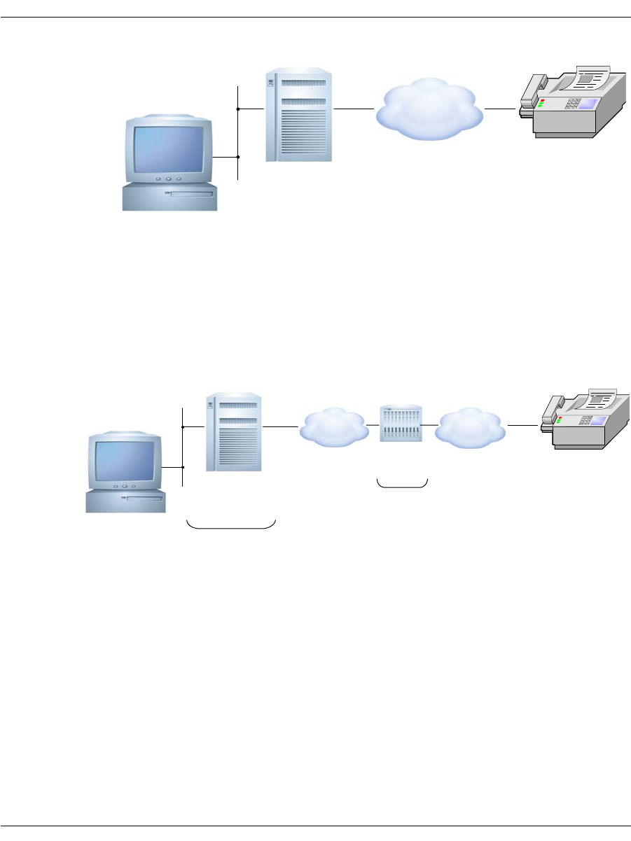
Processing Media Using the T.38 Protocol
November 2009 239
While the method of transport is different, IP environments support
the functionality of these elements.
There are two types of devices used to implement T.38: an endpoint
and a T.38-aware gateway. TR1034-based applications form
endpoints. The following diagram shows how they support a likely IP
fax scenario:
The endpoint uses the T.30 protocol to negotiate the connection and
performs the image conversion. The gateway simply passes the fax
between a PSTN and IP connection.
Brooktrout
Fax Server
Receiving
Fax Machine
Scaling/
transcoding
T.30 /
V.34
T.30 /
V.34
PSTN
Brooktrout
Fax Server
Receiving
Fax Machine
Endpoint
T.30 /
T.38
T.30 /
T.38
PSTN
IP
Gateway

Processing Media Using the T.38 Protocol
November 2009 240
In endpoint facsimile devices, such as a network fax server, the
T.38 protocol provides the equivalent to the modem in traditional
faxing. In a gateway, the T.38 protocol is used to translate
T.30 protocol and image data from the modems in the gateway to and
from the IP endpoint connection, using the following procedure.
1. With T.38 in an endpoint, the application connects a T.38 fax
server to an IP network and transmits the T.30 protocol and fax
image data to the receiving gateway using T.38 packets over the
IP network.
2. The receiving T.38 gateway, in turn, translates the T.38 packets
and repackages them into T.30 protocol signals and transfers
them to the receiving fax machine using modem modulation.
3. The receiving fax machine has a T.30 protocol engine that
communicates with the T.30 protocol engine in the fax server
through the gateway.
4. With T.38 in a gateway, the sending fax machine sends a fax
using modem modulation to transport T.30 protocol and image
data to a gateway via the PSTN.
5. The gateway demodulates the incoming T.30 fax signals and
image data and repackages them into T.38 packets.
6. The gateway then sends the T.38 packets to a T.38 endpoint,
which then delivers the packets in T.30 protocol so the endpoint
can receive the fax.
Gateway-to-gateway scenarios are also possible where two fax
machines communicate using two gateways. In that case, the
T.30 protocol engines in the two fax machines are transported across
the packet network using T.38.
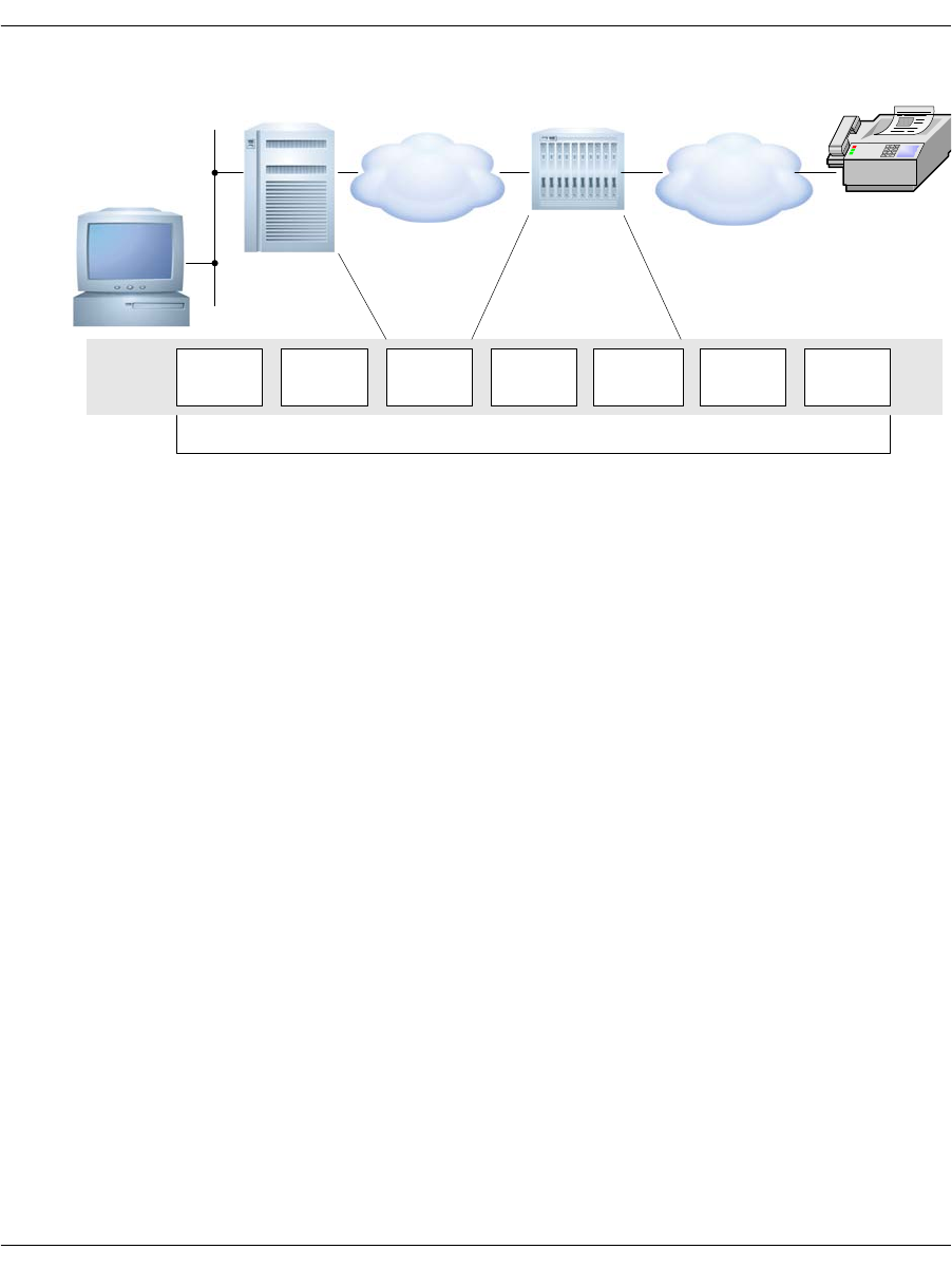
Processing Media Using the T.38 Protocol
November 2009 241
This diagram shows how the protocols work together during the call:
In all cases the application must establish the call first using the IP
call control protocol. The call control protocol is responsible for the
initial call set up and tear down.
Sending and Receiving Faxes
Your application can perform transport independent fax
transmission and reception using the Bfv API fax functions. The
application is unaware of the mode of transport (PSTN or SIP).
Dialogic supports all fax functions for Fax over IP. See Volume 4,
Fax Processing, Bfv API Reference Manual for more information
about Fax functions.
PSTN
End-to-end T.30 Protocol management
IP
T.30
protocol
stack T38 UDP or
TCP T38 Demodulation
Remodulation V.17 T.30
protocol
stack

Configuring T.38, RTP and IP Call Control Activities
November 2009 242
Configuring T.38, RTP and IP Call Control Activities
If your application runs on Windows® systems, you can use the
Brooktrout Configuration Tool to configure call control. Use the IP
Call Control Module Configuration Window to modify values for:
General information
IP parameters for both SIP and H.323
T.38 parameters
RTP parameters
You can also use the following files to configure call control:
The user-defined configuration file
The user-defined configuration file (btcall.cfg) contains
configuration parameters for the Bfv API and driver.
The call control configuration file
The call control configuration file (callctrl.cfg) contains
configuration parameters that define how the user wants the
Bfv API to configure the modules for call control.
See the installation and configuration guide that came with your
software for information about using the Configuration Tool or
Appendix A of the Bfv API Reference Manual, Volume 6 for file
configuration to configure your system and applications to support
fax over IP.

Troubleshooting
November 2009 243
Troubleshooting
You can use any existing Bfv problem solving tools to troubleshoot
your T.38 application. Use the log files created by these tools to
understand what is happening and modify your application. See
Chapter , Debugging on page 91 for more information about these
tools.
Dialogic has provided a debug_control mode for T.38 problem solving
(use under guidance of Dialogic Technical Services and Support). See
Volume 1 of the Bfv API Reference Manual for more information.

Understanding the SIP Protocol
November 2009 244
Understanding the SIP Protocol
You can use the Session Initiation Protocol (SIP), an
application-layer control (signaling) protocol, to create, modify, and
terminate sessions with one or more participants.
These sessions include internet telephone calls, multimedia
distribution, and multimedia conferences. SIP invitations used to
create sessions carry session descriptions that allow participants to
agree on a set of compatible media types. SIP makes use of elements
called proxy servers to help do the following:
Route requests to the user's current location
Authenticate and authorize users for services
Implement provider call-routing policies
Provide features to users.
SIP also provides a registration function that allows users to
upload their current locations for use by proxy servers.
SIP runs on top of several different transport protocols.
This section has the following sections:
Introduction to the SIP Protocol
Overview of SIP Functionality
SIP works with both IPv4 and IPv6.
Introduction to the SIP Protocol
There are many applications of the internet that require the creation
and management of a session (a session is considered to be an
exchange of data between an association of participants). The
implementation of these applications is complicated by the practices
of participants: users might move between endpoints, they might be
addressable by multiple names, and they might communicate in
several different media - sometimes simultaneously. (For copyright
information on this section, see page 255.)

Understanding the SIP Protocol
November 2009 245
Numerous protocols carry various forms of real-time multimedia
session data such as voice, video, or text messages. The Session
Initiation Protocol (SIP) works in concert with these protocols by
enabling internet endpoints (called user agents) to discover one
another and to agree on a characterization of a session they would
like to share.
For locating prospective session participants, and for other
functions, SIP enables the creation of an infrastructure of network
hosts (called proxy servers) to which user agents can send
registrations, invitations to sessions, and other requests. SIP is an
agile, general-purpose tool for creating, modifying, and terminating
sessions that works independently of underlying transport protocols,
regardless of the type of session being established.
Overview of SIP Functionality
SIP is an application-layer control protocol that can establish,
modify, and terminate multimedia sessions (conferences) such as
internet telephony calls. SIP can also invite participants to already
existing sessions, such as multicast conferences. Media is added to
(and removed from) an existing session. SIP transparently supports
name mapping and redirection services, supporting personal
mobility - users can maintain a single externally visible identifier
regardless of their network location.
SIP supports five facets of establishing and terminating multimedia
communications:
User location: determination of the end system to be used for
communication;
User availability: determination of the willingness of the called
party to engage in communications;
User capabilities: determination of the media and media
parameters to be used;
Session setup: “ringing”, establishment of session parameters at
both called and calling party;
Session management: including transfer and termination of
sessions, modifying session parameters, and invoking services.

Understanding the SIP Protocol
November 2009 246
SIP is not a vertically integrated communications system. SIP is
rather a component that is used with other IETF protocols to build a
complete multimedia architecture. Typically, these architectures
include protocols such as the Real-time Transport Protocol (RTP)
(RFC 1889 [28]) for transporting real-time data and providing QoS
feedback, the Real-Time streaming protocol (RTSP) (RFC 2326 [29])
for controlling delivery of streaming media, the Media Gateway
Control Protocol (MEGACO) (RFC 3015 [30]) for controlling
gateways to the Public Switched Telephone Network (PSTN), and
the Session Description Protocol (SDP) (RFC 2327 [1]) for describing
multimedia sessions. Therefore, SIP should be used in conjunction
with other protocols in order to provide complete services to the
users. However, the basic functionality and operation of SIP does not
depend on any of these protocols.
SIP does not provide services. Rather, SIP provides primitives that
are used to implement different services. For example, SIP can
locate a user and deliver an opaque object to the current location. If
this primitive is used to deliver a session description written in SDP,
for instance, the endpoints can agree on the parameters of a session.
If the same primitive is used to deliver a photo of the caller as well as
the session description, a “caller ID” service is easily implemented.
As this example shows, a single primitive is typically used to provide
several different services.
SIP does not offer conference control services such as floor control or
voting and does not prescribe how a conference is to be managed. SIP
is used to initiate a session that uses some other conference control
protocol. Since SIP messages and the sessions they establish can
pass through entirely different networks, SIP cannot, and does not,
provide any kind of network resource reservation capabilities.
The nature of the services provided make security particularly
important. To that end, SIP provides a suite of security services,
which include denial-of-service prevention, authentication (both user
to user and proxy to user), integrity protection, and encryption and
privacy services.
SIP works with both IPv4 and IPv6.

Understanding the SIP Protocol
November 2009 247
Overview of Operation
This section introduces the basic operations of SIP using simple
examples. This section is tutorial in nature and does not contain any
normative statements.
The first example shows the basic functions of SIP:
Locating an end point
Signaling a desire to communicate
Negotiating session parameters to establish the session
Tearing down the established session
Figure 20 on page 248 shows a typical example of a SIP message
exchange between two users, Caller A and Caller B. (Each message
is labeled with the letter “F” and a number for reference by the text.)
In this example, Caller A uses a SIP application on a PC (referred to
as a softphone) to call Caller B on the SIP phone over the internet.
Also shown are two SIP proxy servers that act on behalf of Caller A
and Caller B to facilitate the session establishment. This typical
arrangement is often referred to as the “SIP trapezoid” as shown by
the geometric shape of the dotted lines in Figure 20 on page 248.
Caller A “calls” Caller B using Caller B’s SIP identity, a type of
Uniform Resource Identifier (URI) called a SIP URI. It has a similar
form to an email address, typically containing a user name and a
host name. In this case, it is sip:callerb@biloxi.com, where biloxi.com
is the domain of Caller B's SIP service provider. Caller A has a SIP
URI of sip:callera@atlanta.com. Caller A might have typed in
Caller B's URI or perhaps clicked on a hyperlink or an entry in an
address book. SIP also provides a secure URI, called a SIPS URI. An
example would be sips:callerb@biloxi.com. A call made to a SIPS URI
guarantees that secure, encrypted transport (namely TLS) is used to
carry all SIP messages from the caller to the domain of the callee.
From there, the request is sent securely to the callee, but with
security mechanisms that depend on the policy of the domain of the
callee.
SIP is based on an HTTP-like request/response transaction model.
Each transaction consists of a request that invokes a particular
method, or function, on the server and at least one response. In this
example, the transaction begins with Caller A's softphone sending
an INVITE request addressed to Caller B's SIP URI. INVITE is an
example of a SIP method that specifies the action that the requester
(Caller A) wants the server (Caller B) to take. The INVITE request

Understanding the SIP Protocol
November 2009 248
contains a number of header fields. Header fields are named
attributes that provide additional information about a message. The
ones present in an INVITE include the following:
Unique identifier for the call
Destination address
Caller A's address
Information about the type of session that Caller A wishes to
establish with Caller B.
The INVITE (message F1 in Figure 20) might look like this:
atlanta.com . . . biloxi.com
. proxy proxy .
. .
A's . . . . . . . . . . . . . . . . . . . . . . b's
softphone SIP Phone
| | | |
| INVITE F1 | | |
|--------------->| INVITE F2 | |
| 100 Trying F3 |--------------->| INVITE F4 |
|<---------------| 100 Trying F5 |--------------->|
| |<-------------- | 180 Ringing F6 |
| | 180 Ringing F7 |<---------------|
| 180 Ringing F8 |<---------------| 200 OK F9 |
|<---------------| 200 OK F10 |<---------------|
| 200 OK F11 |<---------------| |
|<---------------| | |
| ACK F12 |
|------------------------------------------------->|
| Media Session |
|<================================================>|
| BYE F13 |
|<-------------------------------------------------|
| 200 OK F14 |
|------------------------------------------------->|
| |
Figure 20. SIP Session Setup Example With Sip Trapezoid

Understanding the SIP Protocol
November 2009 249
INVITE sip:b@biloxi.com SIP/2.0
Via: SIP/2.0/UDP pc33.atlanta.com;branch=z9hG4bK776asdhds
Max-Forwards: 70
To: b <sip:b@biloxi.com>
From: A <sip:a@atlanta.com>;tag=1928301774
Call-ID: a84b4c76e66710@pc33.atlanta.com
CSeq: 314159 INVITE
Contact: <sip:a@pc33.atlanta.com>
Content-Type: application/sdp
Content-Length: 142
(A's SDP not shown)
INVITE Message
Note: Caller A's SDP not shown
The first line of the text-encoded message contains the method name
(INVITE). The lines that follow are a list of header fields. This
example contains a minimum required set. The header fields are
briefly described below:
Via Contains the address (pc33.atlanta.com) at which Caller A is
expecting to receive responses to this request. It also contains a
branch parameter that identifies this transaction.
To Contains a display name (Caller B) and a SIP or SIPS URI
(sip:callerb@biloxi.com) towards which the request was originally
directed. Display names are described in RFC 2822 [3].
From Also contains a display name (Caller A) and a SIP or SIPS URI
(sip:callera@atlanta.com) that indicate the originator of the request.
This header field also has a tag parameter containing a random
string (1928301774) that was added to the URI by the softphone. It
is used for identification purposes.
Call-ID Contains a globally unique identifier for this call, generated by the
combination of a random string and the softphone's host name or IP
address. The combination of the To tag, From tag, and Call-ID
completely defines a peer-to-peer SIP relationship between Caller A
and Caller B and is referred to as a dialog.
CSeq (or Command Sequence) contains an integer and a method name.
The CSeq number is incremented for each new request within a
dialog and is a traditional sequence number.

Understanding the SIP Protocol
November 2009 250
Contact Contains a SIP or SIPS URI that represents a direct route to contact
Caller A, usually composed of a username at a fully qualified domain
name (FQDN). While an FQDN is preferred, many end systems do
not have registered domain names, so IP addresses are permitted.
While the Via header field tells other elements where to send the
response, the Contact header field tells other elements where to send
future requests.
Max-Forwards Serves to limit the number of hops a request can make on the way to
its destination. It consists of an integer that is decremented by one at
each hop.
Content-Type Contains a description of the message body (not shown).
Content-Length Contains an octet (byte) count of the message body.
The details of the session, such as the type of media, codec, or
sampling rate, are not described using SIP. Rather, the body of a SIP
message contains a description of the session, encoded in some other
protocol format. One such format is the Session Description Protocol
(SDP) (RFC 2327 [1]). This SDP message (not shown in the example)
is carried by the SIP message in a way that is analogous to a
document attachment being carried by an email message, or a web
page being carried in an HTTP message.
Since the softphone does not know the location of Caller B or the SIP
server in the biloxi.com domain, the softphone sends the INVITE to
the SIP server that serves Caller A's domain, atlanta.com. The
address of the atlanta.com SIP server could have been configured in
Caller A's softphone, or it could have been discovered by the
Dynamic Host Configuration Protocol (DHCP), for example.
The atlanta.com SIP server is a type of SIP server known as a proxy
server. A proxy server receives SIP requests and forwards them on
behalf of the requestor. In this example, the proxy server receives
the INVITE request and sends a 100 (Trying) response back to
Caller A's softphone. The 100 (Trying) response indicates that the
INVITE has been received and that the proxy is working on
Caller A’s behalf to route the INVITE to the destination. Responses
in SIP use a three-digit code followed by a descriptive phrase. This
response contains the same To, From, Call-ID, CSeq and branch
parameter in the Via as the INVITE, which allows Caller A's
softphone to correlate this response to the sent INVITE. The
atlanta.com proxy server locates the proxy server at biloxi.com,
possibly by performing a particular type of DNS (Domain Name
Service) lookup to find the SIP server that serves the biloxi.com
domain. This is described in [4]. As a result, it obtains the IP address

Understanding the SIP Protocol
November 2009 251
of the biloxi.com proxy server and forwards, or proxies, the INVITE
request there. Before forwarding the request, the atlanta.com proxy
server adds an additional Via header field value that contains its
own address (the INVITE already contains Caller A's address in the
first Via). The biloxi.com proxy server receives the INVITE and
responds with a 100 (Trying) response back to the atlanta.com proxy
server to indicate that it has received the INVITE and is processing
the request. The proxy server consults a database, generically called
a location service, that contains the current IP address of Caller B.
The biloxi.com proxy server adds another Via header field value with
its own address to the INVITE and proxies it to Caller B's SIP
phone.
Caller B's SIP phone receives the INVITE and alerts Caller B to the
incoming call from Caller A so that Caller B can decide whether to
answer the call, that is, Caller B's phone rings. Caller B's SIP phone
indicates this in a 180 (Ringing) response, which is routed back
through the two proxies in the reverse direction. Each proxy uses the
Via header field to determine where to send the response and
removes its own address from the top. As a result, although DNS and
location service lookups were required to route the initial INVITE,
the 180 (Ringing) response is returned to the caller without lookups
or without state being maintained in the proxies. This also has the
desirable property that each proxy that sees the INVITE also sees all
responses to the INVITE.
When Caller A's softphone receives the 180 (Ringing) response, it
passes this information to Caller A, perhaps using an audio ringback
tone or by displaying a message on Caller A's screen.

Understanding the SIP Protocol
November 2009 252
In this example, Caller B decides to answer the call. When he picks
up the handset, the SIP phone sends a 200 (OK) response to indicate
that the call has been answered. The 200 (OK) contains a message
body with the SDP media description of the type of session that
Caller B is willing to establish with Caller A. As a result, there is a
two-phase exchange of SDP messages: Caller A sent one to Caller B,
and Caller B sent one back to Caller A. This two-phase exchange
provides basic negotiation capabilities and is based on a simple
offer/answer model of SDP exchange. If Caller B did not wish to
answer the call or was busy on another call, an error response would
have been sent instead of the 200 (OK), which would have resulted in
no media session being established. The 200 (OK) (message F9 in
Figure 20 on page 248) might look like this as Caller B sends it out:
SIP/2.0 200 OK
Via: SIP/2.0/UDP server10.biloxi.com; branch=z9hG4bKnashds8;
received=192.0.2.3
Via: SIP/2.0/UDP bigbox3.site3.atlanta.com; branch=z9hG4bK77ef4c2312983.1;
received=192.0.2.2
Via: SIP/2.0/UDP pc33.atlanta.com; branch=z9hG4bK776asdhds;
received=192.0.2.1
To: b <sip:b@biloxi.com>;tag=a6c85cf
From: A <sip:a@atlanta.com>;tag=1928301774
Call-ID: a84b4c76e66710@pc33.atlanta.com
CSeq: 314159 INVITE
Contact: <sip:b@192.0.2.4>
Content-Type: application/sdp
Content-Length: 131
(Caller B's SDP not shown)
The first line of the response contains the response code (200) and
the reason phrase (OK). The remaining lines contain header fields.
The Via, To, From, Call-ID, and CSeq header fields are copied from
the INVITE request. (There are three Via header field values - one
added by Caller A's SIP phone, one added by the atlanta.com proxy,
and one added by the biloxi.com proxy.) Caller B's SIP phone has
added a tag parameter to the To header field. This tag is
incorporated by both endpoints into the dialog and is included in all
future requests and responses in this call. The Contact header field
contains a URI at which Caller B can be directly reached at a SIP
phone. The Content-Type and Content-Length refer to the message
body (not shown) that contains Caller B's SDP media information.
In addition to DNS and location service lookups shown in this
example, proxy servers can make flexible “routing decisions” to
decide where to send a request. For example, if Caller B's SIP phone
returned a 486 (Busy Here) response, the biloxi.com proxy server

Understanding the SIP Protocol
November 2009 253
could proxy the INVITE to Caller B's voicemail server. A proxy
server can also send an INVITE to a number of locations at the same
time. This type of parallel search is known as forking (see below).
In this case, the 200 (OK) is routed back through the two proxies and
is received by Caller A's softphone, which then stops the ringback
tone and indicates that the call has been answered. Finally,
Caller A's softphone sends an acknowledgement message, ACK, to
Caller B's SIP phone to confirm the reception of the final response
(200 (OK)). In this example, the ACK is sent directly from Caller A's
softphone to Caller B's SIP phone, bypassing the two proxies. This
occurs because the endpoints have learned each other's address from
the Contact header fields through the INVITE/200 (OK) exchange,
which was not known when the initial INVITE was sent. The
lookups performed by the two proxies are no longer needed, so the
proxies drop out of the call flow. This completes the
INVITE/200/ACK three-way handshake used to establish SIP
sessions.
Caller A and Caller B's media session has now begun, and they send
media packets using the format to which they agreed in the
exchange of SDP. In general, the end-to-end media packets take a
different path from the SIP signaling messages.
During the session, either Caller A or Caller B may decide to change
the characteristics of the media session. This is accomplished by
sending a re-INVITE containing a new media description. This
re-INVITE references the existing dialog so that the other party
knows that it is to modify an existing session instead of establishing
a new session. The other party sends a 200 (OK) to accept the
change. The requestor responds to the 200 (OK) with an ACK. If the
other party does not accept the change, he sends an error response
such as 488 (Not Acceptable Here), which also receives an ACK.
However, the failure of the re-INVITE does not cause the existing
call to fail - the session continues using the previously negotiated
characteristics.
At the end of the call, Caller B disconnects (hangs up) first and
generates a BYE message. This BYE is routed directly to Caller A's
softphone, again bypassing the proxies. Caller A confirms receipt of
the BYE with a 200 (OK) response, which terminates the session and
the BYE transaction. No ACK is sent - an ACK is only sent in
response to an INVITE request. The reasons for this special
handling for INVITE relate to the reliability mechanisms in SIP, the
length of time it can take for a ringing phone to be answered, and

Understanding the SIP Protocol
November 2009 254
forking. For this reason, request handling in SIP is often classified
as either INVITE or non- INVITE, referring to all other methods
besides INVITE.
In some cases, it may be useful for proxies in the SIP signaling path
to see all the messaging between the endpoints for the duration of
the session. For example, if the biloxi.com proxy server wished to
remain in the SIP messaging path beyond the initial INVITE, it
would add to the INVITE a required routing header field known as
Record- Route that contained a URI resolving to the hostname or IP
address of the proxy. This information would be received by both
Caller B's SIP phone and (due to the Record-Route header field being
passed back in the 200 (OK)) Caller A's softphone and stored for the
duration of the dialog. The biloxi.com proxy server would then
receive and proxy the ACK, BYE, and 200 (OK) to the BYE. Each
proxy can independently decide to receive subsequent messages, and
those messages pass through all proxies that elect to receive it. This
capability is frequently used for proxies that are providing mid-call
features.
Registration is another common operation in SIP. Registration is one
way that the biloxi.com server can learn the current location of
Caller B. Upon initialization, and at periodic intervals, Caller B's
SIP phone sends REGISTER messages to a server in the biloxi.com
domain known as a SIP registrar. The REGISTER messages
associate Caller B's SIP or SIPS URI (sip:callerb@biloxi.com) with
the machine into which he is currently logged (conveyed as a SIP or
SIPS URI in the Contact header field). The registrar writes this
association, also called a binding, to a database, called the location
service, where it is used by the proxy in the biloxi.com domain.
Often, a registrar server for a domain is co-located with the proxy for
that domain. It is an important concept that the distinction between
types of SIP servers is logical, not physical.
Caller B is not limited to registering from a single device. For
example, both the SIP phone at home and the one in the office could
send registrations. This information is stored together in the location
service and allows a proxy to perform various types of searches to
locate Caller B. Similarly, more than one user is registered on a
single device at the same time.
The location service is just an abstract concept. It generally contains
information that allows a proxy to input a URI and receive a set of
zero or more URIs that tell the proxy where to send the request.

Understanding the SIP Protocol
November 2009 255
Registrations are one way to create this information, but not the only
way. Arbitrary mapping functions are configured at the discretion of
the administrator.
Finally, it is important to note that in SIP, registration is used for
routing incoming SIP requests and has no role in authorizing
outgoing requests. Authorization and authentication are handled in
SIP either on a request-by-request basis with a challenge/response
mechanism, or by using a lower layer scheme.
Full Copyright Statement
Copyright (C) The Internet Society (2002). All Rights Reserved.
This document and translations of it may be copied and furnished to others, and
derivative works that comment on or otherwise explain it or assist in its
implementation may be prepared, copied, published and distributed, in whole or in
part, without restriction of any kind, provided that the above copyright notice and this
paragraph are included on all such copies and derivative works. However, this
document itself may not be modified in any way, such as by removing the copyright
notice or references to the Internet Society or other Internet organizations, except as
needed for the purpose of developing Internet standards in which case the procedures
for copyrights defined in the Internet Standards process must be followed, or as
required to translate it into languages other than English.
The limited permissions granted above are perpetual and will not be revoked by the
Internet Society or its successors or assigns.
This document and the information contained herein is provided on an “AS IS” basis
and THE INTERNET SOCIETY AND THE INTERNET ENGINEERING TASK
FORCE DISCLAIMS ALL WARRANTIES, EXPRESS OR IMPLIED, INCLUDING
BUT NOT LIMITED TO ANY WARRANTY THAT THE USE OF THE
INFORMATION HEREIN WILL NOT INFRINGE ANY RIGHTS OR ANY IMPLIED
WARRANTIES OF MERCHANTABILITY OR FITNESS FOR A PARTICULAR
PURPOSE.

Using Third Party IP Stacks
November 2009 256
Using Third Party IP Stacks
The Bfv Fax can be integrated with systems that have their own IP
call control stacks. The primary IP stacks are SIP and H.323. These
stacks negotiate an RTP and a T.38 port to perform fax. With the use
of the SR140 software, a pure fax software solution can be integrated
on systems that have VoIP features.
Systems that have available board slots can take advantage of the
TR1034-N board to unload CPU cycles from the system to the board
for fax processing. With this integration, it will be up to the third
party IP stack to negotiate RTP and T.38 ports.
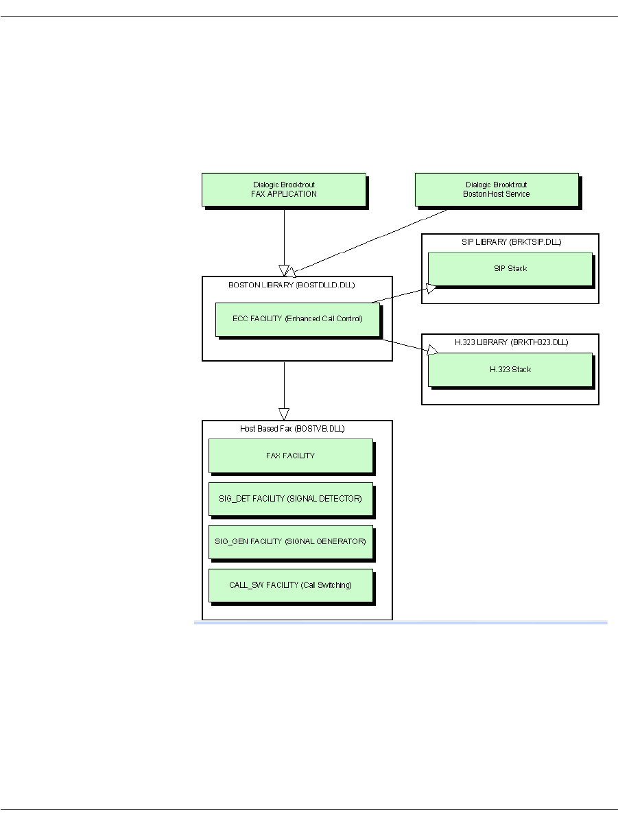
Using Third Party IP Stacks
November 2009 257
Integrating Bfv IP Fax
Figure 21 shows the individual components that an application
interacts with via the Bfv API. Although other facilities exist in the
Bfv, only the fax-related facilities are shown below.
Figure 21. Components Interacting with Application
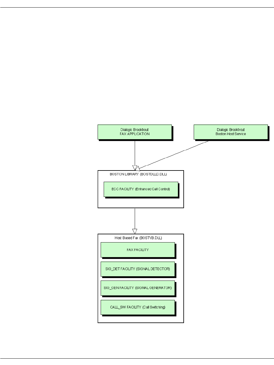
Using Third Party IP Stacks
November 2009 258
Components
The following figure shows the components included in this
configuration. Note that you must disable the functionality of the
following:
ECC Component
H.323 Stack
SIP Stack
Refer to Disable ECC Component on page 259 which disables the
stacks too.
Figure 22. Components in Configuration

Using Third Party IP Stacks
November 2009 259
Configuration
You can configure the Bfv with the ConfigTool on Windows® or by
creating the callctrl.cfg files manually.
The ConfigTool is a full-solution configuration because the call
control is included in the configuration along with the IP Stack
which has been integrated with BFV.
It can be used to create the initial callctrl.cfg and btcall.cfg.
However, for this setup, you must edit the callctrl.cfg manually.
Dialogic does not recommend that you use ConfigTool beyond the
initial creation of the configuration files. Refer to the Call Control
Configuration File section in the Dialogic® Brooktrout® Bfv
Reference Manual for more information on the parameters available
in callctrl.cfg.
Disable ECC Component
To disable the ECC component and allow a third party to manage
call control, remove the following sections in callctrl.cfg:
[module.X/host_cc.1]
[host_module.1]
[host_module.1/t38parameters]
[host_module.1/parameters]
The following callctrl.cfg examples are for Linux with paths to the
default installation directory.
SR140 Software-Based Integration - Linux
The following callctrl.cfg configuration is an example for an SR140
“pure” software based integration for Linux in the default
installation directory.
# callctrl.cfg
#
# Sample Call Control configuration file for Boston Bfv
API with SR140.

Using Third Party IP Stacks
November 2009 260
#
[module.41]
vb_firm=/usr/sys/brooktrout/boston/fw/bostvb.so
# This parameter should be set to the number of channels
licensed for the SR140 product
channels=30
[module.41/ethernet.1]
ip_interface=eth0
TR1034 Board-Based Integration - Linux
The following callctrl.cfg configuration is an example for a TR1034
board based integration for Linux in the default installation
directory.
# callctrl.cfg
#
# Sample Call Control configuration file for Boston Bfv
API with Tr1034.
#
[module.2]
cc_type=1
channels=30
set_api=bfv
pcm_law=mulaw
[module.2/clock_config]
clock_mode=master
clock_source=internal
clock_compatibility=none
bus_speed=2
master_ref_fallback=disabled
master_drive=clock_a
[module.2/ethernet.1]
# Specify a staic IP address such as 192.168.0.2
ip_address=0.0.0.0

Using Third Party IP Stacks
November 2009 261
# Specify an IP mask such as 255.255.255.0
ip_netmask=0.0.0.0
# Specify an IP address such as 192.168.0.1
ip_gateway=0.0.0.0
ip_broadcast=0.0.0.0
ethernet_speed=auto
ip_arp_timeout=10
Call Negotiation
Inbound Call
The following section uses SIP to demonstrate the interaction
between the third party stack in the application and the Bfv API for
negotiating RTP and T.38 for an inbound call.
Systems that will perform RTP can generate the CED tone and avoid
setting the RTP on the Bfv. If this is the case, applications can skip
calling BfvCallSWConnectIP(FullDuplex RTP) and
BfvTonePlayBeep() CED.
If both RTP and T.38 are done with the Bfv API, some ICMP errors
may appear as the port is switched from RTP to T.38. To avoid the
ICMP errors use unique ports for RTP and T.38.

Using Third Party IP Stacks
November 2009 262
Figure 23. Inbound SIP Sequence
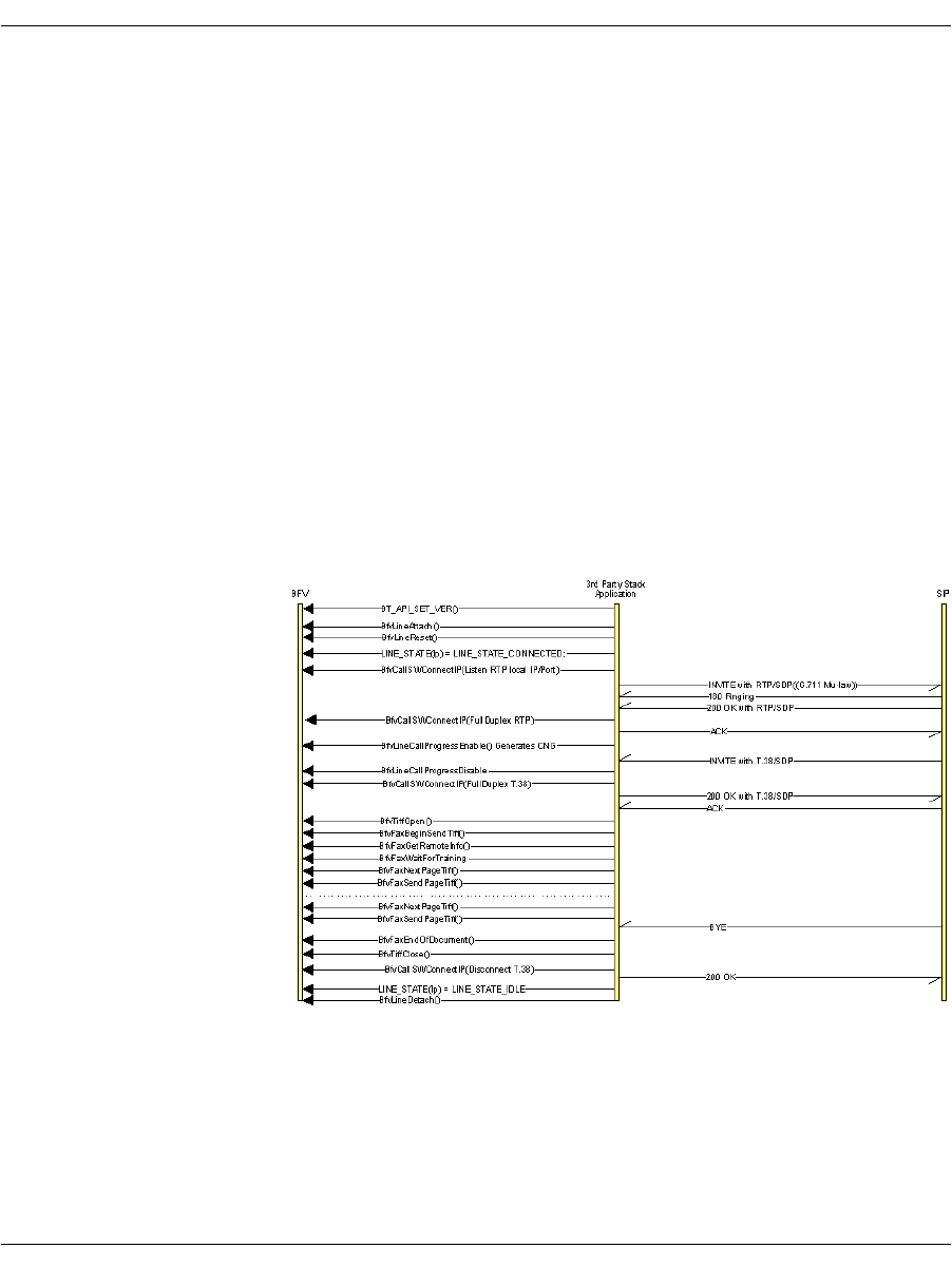
Using Third Party IP Stacks
November 2009 263
Outbound Call
The following section uses SIP to demonstrate the interaction
between the third party stack in the application and Bfv for
negotiating RTP and T.38 for an outbound call.
Systems that will perform RTP can generate the CNG tone and
avoid setting the RTP on the Bfv. If this is the case applications can
skip calling BfvCallSwitchConnectIP(Listen RTP local IP/Port),
BfvCallSWConnectIP(FullDuplex RTP),
BfvLineCallProgressEnable() Generates CNG, and
BfvLineCallProgressDisable.
If RTP is also going to be done with the Bfv, make sure the port used
in BfvCallSWConnectIP is unused.
If both RTP and T.38 are done with Bfv, some ICMP errors may
appear as the port is switched from RTP to T.38. To avoid the ICMP
errors use unique ports for RTP and T.38.
Figure 24. Outbound SIP Sequence

November 2009 264
7 - Robbed Bit Signaling
This chapter describes robbed bit signaling as used with BSMI-level
call control.
The chapter has the following sections:
General Information
Wink Start & Delay Dial Signaling
Wink Start with Feature Group B & D
Immediate Start/Fixed Pause Signaling
Ground Start Signaling
Loop Start Signaling
FXO Loop Start
General Information
This chapter covers protocols Dialogic supports for interfacing with
the Local Exchange Carrier (LEC) Network (that is, the North
American Telephone Network).
Note: This chapter applies only to BSMI (low-level call control)
users. Bfv call control users do not need to be concerned with
this information.

General Information
November 2009 265
These protocols apply either to digital (T1 or E1) or analog lines. The
different types of lines simply provide a different mechanism for
conveying the signal-electric signals (loop current and ring voltage)
on analog lines and bits on digital lines.
On digital lines, these protocols are sometimes referred to as
Channel Associated Signaling (CAS) or Robbed-Bit Signaling (RBS)
due to the nature of the signaling. Each channel's state is
represented as a set of 2 signaling bits, and these bits are
transmitted on the line at constant intervals. The LEC protocols are
normally associated with T1 lines, where they were originally used,
but nowadays it is possible to find these protocols used in PBX's
using E1 lines (which provide 4 signaling bits per channel).
A different technique is to reserve a full channel on a T1 or E1 line to
carry information about all channels, and to use the available bits as
a continuous stream carrying information “packets” instead of
repeating a number of signaling bits over time. This technique is
called Common-Channel Signaling (CCS), and is used on ISDN lines
among others.
In T1 lines, audio and line state information is grouped in frames,
each frame consists of 8 bits of data for each of the 24 channels, plus
a framing bit, adding to 193 bits/frame (8 bits/byte * 1 byte/channel *
24 channels/frame + 1bit). The sampling rate is 8000 Hz, so the bit
rate is 8000x193=1,544,000, or 1.544 Mb/s.
The technique used for carrying the signaling bits on T1 is to use
(“rob,” hence the term Robbed-Bit Signaling) some of the bits
normally intended to represent data (voice/fax/data) on a channel for
the purposes of call control. Research has shown that robbing the
least significant bit of each channel's sample every 6th frame causes
a virtually imperceptible (for humans) level of distortion for voice.
However, when raw data is being sent, this loss becomes
unacceptable, so for simplicity only 7 of the 8 bits are used for data
applications. This technique allows for all 24 channels to be used for
calls, as opposed to 23 channels used for calls and one for call control
(23B+D), as with ISDN.
In E1 lines (32 timeslots per line), one of the timeslots (0) in each
frame is reserved for framing and synchronization data, and another
(timeslot 16) is used for the signaling bits — in the first frame it
carries information about audio timeslots 1 and 17, in the second
frame for timeslots 2 and 18 and so on until all audio channels are
covered, and then the process starts over.

General Information
November 2009 266
The protocols describe the value and meaning of the signaling bits
and the timing between changes in their value.
Brooktrout modules support the following LEC protocols:
E&M Wink Start
E&M Immediate Start
E&M Delay Dial
FXO Loop Start
FXS Loop Start
FXO Ground Start
FXS Ground Start
All signaling modes support pulsed (10 pulses per second), DTMF
and MF dialing. However, detection of digits must be handled by the
host.
ITU's R2 protocol, normally used in E1 lines is also supported, and it
is described in Using the BSMI R2 Signaling Capability on page 336.
Wink Start, Immediate Start and Delay Dial protocols are typically
used to connect equivalent devices (for example, Central Offices).
The same protocol must be loaded on both channel involved in a call.
Loop Start and Ground Start protocols connect different types of
devices (a Central Office or PBX to a Station). In this case the side
acting as Central Office must load the FXO (foreign exchange office)
version of the protocol, while the Station side must load the FXS
(foreign exchange station) version.
The messages and data structures used for the host application and
the module to communicate form the BSMI interface, described in
Volume 5 of the Bfv API Reference Manual. The same Bfv API is
used also for ISDN and R2 — the same messages are used to
control/notify similar events across all protocols.
Structure IISDN_BCHANNEL_ID contains fields common to all
CAS protocols plus data structures containing LEC- and R2-specific
configuration (structures IISDN_ROBBED_BIT_DATA and IISDN_
E1_CAS_R2_DATA respectively). Some of the message fields have
names that reflect their ISDN roots, but their definition is extended
for use with all CAS protocols (LEC protocols as well as R2). The
most important ones are lapdid, which in CAS protocols identifies
the trunk number in the module (0-based) and call_ref, a 16-bit
value in which the most-significant byte must always contain the
trunk number (same value as lapdid) and the least significant byte

General Information
November 2009 267
the B-channel number on that trunk (also 0-based). Some of the data
structures associated with the message will have a specific field for
specifying the B-channel, which must also be set.
Enabling a channel and selecting the protocol to run is done through
message L4L3mENABLE_CAS, while message L4L3mDISABLE_
CAS is used to disable a channel. It is possible to have different
channels on the same T1 trunk running different protocols. Once a
DS0 channel is configured to run a LEC protocol most processing
specific to that protocol, is handled by the module. Channels are
numbered 0-(N-1) for all line types (T1, E1 and analog) and
protocols.
Dialogic supports the most common protocols. Contact Dialogic to
make requests for ones not known to be officially supported. See
Getting Technical Support on page 21 for contact information.

General Information
November 2009 268
Timer Definitions
The LEC structure (named IISDN_ROBBED_BIT_DATA for
historical reasons) contains a series of 16-bit values used to configure
the various timing parameters associated with the protocols.
Table 13 lists the timers in alphabetical order and contains each
timer's unit, meaning, and default value. The unit indicates by how
much a timer value must be multiplied to find its actual duration in
milliseconds, while the default (the number in parentheses following
its define value) indicates the number of ticks.
Proper timing with LEC protocols is very important. There are over
30 unique timings that are set, with a significant subset of these
applicable to several protocols. You should match their entries in the
table to the appropriate timing diagrams.
Table 13. Robbed Bit Signaling Timers
Timer Granularity Definition Default Value
answer_timer 50 ms Timed Answer Supervision.
Timer started after the last digit
has been dialed. Used to report
distant end answer when the
protocol doesn't provide a
specific signal to indicate the
called party has answered the
call.
IISDN56_ANSW_TIMER_
DEFAULT (60)
3 seconds
critical_timer 50 ms Critical Interdigit Timer. While
racking incoming distant digits,
the maximum time to wait
between digits before giving up
and returning an incomplete
rack.
IISDN56_CRIT_TIMER_
DEFAULT (20)
1 second

General Information
November 2009 269
delayed_on_
hook_timer 50 ms Delayed on hook timer. If set to a
value greater than 0, the
amount of time it waits for the
host to set the line onhook
(message L4L3mCLEAR_
REQUEST) after the protocol
has detected termination of the
call. If this timer expires, the
protocol sets the line onhook
automatically. If this value is set
to 0 or infinity (0xFFFF), the
protocol waits forever for the
host to set the line onhook. The
timer is only used if field
delayed_onhook_mode is set to
TRUE.
IISDN56_DELAYED_ON_
HOOKTIMER_DEFAULT (20)
1 second
delayed_wink_
timer 20 ms Delayed Wink timer. If set to a
value greater than 0, the
amount of time it waits for the
host to send the wink ((message
L4L3mTX_WINK) after the
protocol has detected an
incoming call. If this timer
expires, the protocol sends the
wink automatically. If this value
is set to 0 or infinity (0xFFFF),
the protocol waits forever for the
host to send the wink. The timer
is only used if field delayed_
wink_mode is set to TRUE.
IISDN_DELAYED_WINK_
TIMER_DEFAULT (20)
1 second
dptimer_break 10 ms Dial Pulse Break.
On-hook (break) time for
outdialing a dial pulse digit.
IISDN56_DPBREAK_TIMER_
DEFAULT (4)
40 ms
dptimer_end_
dial_pause 10 ms Dial Pulse Pause After Dialing.
Time after outpulsing the last
digit before Instant ISDN sends
any supervision signals or
receives answer supervision.
IISDN56_DPEND_DIAL_TIMER_
DEFAULT (5)
50 ms
dptimer_
immed_delay 10 ms Dial Pulse Immediate Delay.
Time after an incoming seizure
before Instant ISDN will accept
incoming dial pulse digits.
IISDN56_IMMED_DELAY_
TIMER_DEFAULT (10)
100 ms
Table 13. Robbed Bit Signaling Timers (Continued)
Timer Granularity Definition Default Value

General Information
November 2009 270
dptimer_
interdigit 10 ms Dial Pulse Interdigit.
Time between digits when
performing digit outpulsing.
IISDN56_DPINTERDGT_TIMER_
DEFAULT (30)
300 ms
dptimer_make 10 ms Dial Pulse Make.
Off-hook (make) time for
outdialing a dial pulse digit.
IISDN56_DPMAKE_TIMER_
DEFAULT (6)
60 ms
dptimer_post_
wink 10 ms Amount of time the protocol will
keep the line in idle state after
transmission of a wink signal
before reporting to the host the
wink has been sent. This
ensures a minimum period for
the idle signal to be present on
the line, even if the host sends
the line offhook immediately
after being notified of an
incoming call or end of a
transmitted wink.
IISDN56_DPPOSTWINK_TIMER_
DEFAULT (5)
50 ms
dptimer_pre_
wink 10 ms Dial Pulse Prewink.
Time Instant ISDN pauses
before sending a wink signal.
IISDN56_DPPREWINK_TIMER_
DEFAULT (5)
50 ms
dptimer_wink 10 ms Duration of a transmitted wink. IISDN56_DPWINK_TIMER_
DEFAULT (20)
200 ms
first_indigit_
timer 50 ms Normal First Interdigit Timer.
While racking incoming digits,
the maximum time to wait for
the first digit before giving up
and returning an incomplete
rack (valid during normal
interdigit timing only).
IISDN56_FIRST_DGT_TIMER_
DEFAULT (60)
3 seconds
fixed_pause_
timer 50 ms Fixed Pause Wait Timer.
Time to wait before allowing
outgoing dialing to commence
(applies when outgoing start dial
type is fixed pause only).
IISDN56_FIXP_TIMER_
DEFAULT (2)
100 ms
Table 13. Robbed Bit Signaling Timers (Continued)
Timer Granularity Definition Default Value

General Information
November 2009 271
glare_
detection_
timer
10 ms Glare Detection.
Timer started at the beginning
of outseizure that determines if
a wink start or delay dial was
returned too quickly to be an
acknowledgment of the
outseizure, but should be treated
as glare.
IISDN56_GLARE_TIMER_
DEFAULT (5)
50 ms
guard_
interval_timer 50 ms Guard Interval Timer. Time
after the circuit becomes idle
before it is used for another
outgoing call.
IISDN56_GUARD_TIMER_
DEFAULT (20)
1 second
hookflash_
timer 10 ms Hookflash Timer. Duration of a
transmitted hook flash signal. IISDN56_HOOKFLASH_TIMER_
DEFAULT(80)
800 ms
hooktimer_
onhook_rls 10 ms Normal Outgoing Release Filter.
Filter on receive signal bit
detector or the amount of time it
must be idle before distant end
releasing is assumed. This filter
is in effect some time after
answer (specified by modified
outgoing release time) until
completion of call.
IISDN56_ONHK_TIMER_
DEFAULT (50)
500 ms
hooktimer_
onhk_mod_in_
rls
10 ms Modified Incoming Release
Filter.
Filter on receive signal bit
detector or the amount of time it
must be idle before distant end
releasing is assumed. This filter
is in effect from inseizure until
sometime after answer (specified
by modified incoming release
time).
IISDN56_MOD_ONHK_IN_
TIMER_
DEFAULT (80)
800 ms
hooktimer_
onhk_mod_
out_rls
10 ms Modified Outgoing Release
Filter. Filter on receive signal
bit detector or the amount of
time it must be idle before
distant end releasing is
assumed. This filter is in effect
from answer until some time
after answer (specified by
modified outgoing release time).
IISDN56_MOD_ONHK_OUT_
TIMER_DEFAULT (80)
800 ms
Table 13. Robbed Bit Signaling Timers (Continued)
Timer Granularity Definition Default Value

General Information
November 2009 272
hooktimer_
offhook_inseize 10 ms Inseizure Filter.
Time that the receive signal bit
must be in-use to be considered
an inseizure from the connected
equipment.
IISDN56_OFHK_INSZ_TIMER_
DEFAULT (5)
50 ms
hooktimer_
offhook_
answer
10 ms Answer Filter.
Filter used on the receive signal
bit during the interval during
which Instant ISDN is looking
for an answer from the
connected equipment.
IISDN56_OFHK_ANS_TIMER_
DEFAULT (10)
100 ms
hooktimer_
min_wink 10 ms Wink Filter.
Minimum off-hook that will be
interpreted as a valid start dial
signal when outgoing start dial
is selected as wink start or delay
dial.
IISDN56_MIN_WINK_TIMER_
DEFAULT (10)
100 ms
hooktimer_
maxmake 10 ms Longest make duration that is
counted as part of a dial pulse.
A longer make signal will cause
digit racking to be terminated.
IISDN56_MAXMAKE_TIMER_
DEFAULT (8)
8 ms
hooktimer_
maxbreak 10 ms Longest break duration that is
counted as part of a dial pulse.
A longer break signal will be
considered the end of a pulse
digit. If the duration eventually
exceeds the value specified in
field critical timer, it is
interpreted as a disconnection
signal.
IISDN56_MAXBREAK_TIMER_
DEFAULT (8)
8 ms
hooktimer_
minmake 10 ms Minimum Dial Pulse Make
Time.
Shortest make region that is
counted as a dial pulse make
region. Anything shorter should
be ignored.
IISDN56_MINMAKE_TIMER_
DEFAULT (1)
1 ms
Table 13. Robbed Bit Signaling Timers (Continued)
Timer Granularity Definition Default Value

General Information
November 2009 273
hooktimer_
minbreak 10 ms Minimum Dial Pulse Break
Time.
Shortest break region that is
counted as a dial pulse break
region. Anything shorter should
be ignored.
IISDN56_MINBREAK_TIMER_
DEFAULT (1)
1 ms
ign_insz_post_
rls_timer 10 ms Ignore Inseize After Release
Timer.
Time after the interface has
idled before Instant ISDN will
allow an inseizure from the
connected equipment.
IISDN56_IGNINSZ_TIMER_
DEFAULT (5)
50 ms
ign_rls_post_
ans_timer 10 ms Ignore Release After Answer
Timer.
Time after the call has been
answered before Instant ISDN
will allow the connected
equipment to try to tear down
the call.
IISDN56_IGNRLS_TIMER_
DEFAULT (5)
50 ms
modified_in_
rls_timer 50 ms Modified Incoming Release
Timer.
Timer started at answer that
determines when modified
incoming release filter timing
ends and normal incoming
release filter timing begins.
IISDN56_MOD_INRLS_TIMER_
DEFAULT (10)
500 ms
modified_out_
rls_timer 50 ms Modified Outgoing Release
Timer.
Timer started at answer that
determines when modified
outgoing release filter timed
ends, and normal outgoing
release filter timing begins.
IISDN56_MOD_OUTRLS_TIMER_
DEFAULT (10)
500 ms
no_ringing_
timer 50 ms Interval between rings during
the ring cycle on outbound calls
(FXS Loop Start and FXS
Ground Start calls only).
IISDN56_NO_RINGING_TIMER_
DEFAULT (80)
4 seconds
Table 13. Robbed Bit Signaling Timers (Continued)
Timer Granularity Definition Default Value

General Information
November 2009 274
outseize_ack_
timer 50 ms CO Outseize Acknowledge
Timer.
Time to continue looking for the
outgoing start dial signal from
the connected equipment on
outseizure before declaring an
outseizure failure.
IISDN56_OUTS_ACK_TIMER_
DEFAULT (60)
3 seconds
ringing_timer 50 ms Duration of ring signal during
the ring cycle on outbound calls
(FXS Loop Start and FXS
Ground Start calls only).
IISDN56_RINGING_TIMER_
DEFAULT (40)
2 seconds
Table 13. Robbed Bit Signaling Timers (Continued)
Timer Granularity Definition Default Value

General Information
November 2009 275
Timing Diagrams
To aid in the development process, timing diagrams that illustrate
call setup and call teardown signaling in the various supported
protocols are provided in the sections that follow. The diagrams
consist of four parts:
IISDN SMI Messages: Indicates the Bfv API messages sent to
and received from the card during the call scenario.
IISDN Timers: The timers possibly in use during the call
scenario are listed, and active only during the periods on the
diagram where the graph blocks are shaded.
Receive and Transmit Signaling Bits: The thick black lines
represent the signaling bits used to represent the call states in
each protocol. Wink Start, Immediate Start/Fixed Pause and
Delay protocols use only one bit (A-bit) to carry information, so
only one line is shown for each direction. In these protocols, the
value of the A-bit is seen as the “hook switch state” (“on hook” is
low or zero, “off hook” is high or one). FXO/FXS Loop Start and
Ground Start protocols use 2 signaling bits, A and B, to carry
information, so two lines are shown for each direction. In these
protocols, the bit values represent current feed and ring signal
(FXO protocols), and hook state/ring current and ring ground
(FXS protocols).
Arrows and Vertical Dashed Lines: The arrows and vertical
dashed lines indicate that there is a causal relationship between
an event that occurs to the start of other events. For instance,
the expiration of a timer can result in a change in the hook
switch state, or a change in hook switch state can result in the
start of a timer and issuance of an L3L4 message.
Note: The diagrams are designed to give the reader a general
understanding of the sequence of events for various robbed bit
protocols over time. The timers and spacing on the graphs are
not proportional to the actual events that occur.

Wink Start & Delay Dial Signaling
November 2009 276
Wink Start & Delay Dial Signaling
In the Wink Start protocol, the device seizing the line expects a wink
signal (a short-duration - 140 to 290ms - offhook signal) to be sent
back as acknowledgment before sending the address digits.
In the Delay Dial, the device seizing the line expects an off-hook
response from the far end for at lest 140ms, and waits for the far end
to return to on-hook state before sending the address digits.
Although the protocols are different, the sequence of signals sent by
both Wink Start and Delay Dial protocols is virtually identical, so
these two protocols are often handled together.
Only two signaling bit patterns are used for these protocols.
Pattern 00 (A and B bits zero) indicates the line is idle, while AB =
11 indicates a line seizure on the initiating end and the off-hook
signal on the receiving end. Since the two bits must always have the
same value, usually only the A bit is verified and the B bit ignored,
thus eliminating the need to handle invalid bit patterns.
Wink start and delay dial trunks use almost identical signaling. To
configure a Brooktrout module for standard wink start signaling, the
host must issue an L4L3mENABLE_CAS with an IISDN_ROBBED_
BIT_DATA structure that contains the following settings:
send_glare_err_event = 0 (not used for wink start)
in_trunk_type = IISDNttWINK_START (the default value)
out_trunk_type = IISDNttWINK_START (the default value)
fgb_fgd_mode = 0 (refer to Wink Start with Feature Group B
& D on page 281 for wink start with Feature Group B and D
signaling)
To configure a Brooktrout module for delay dial signaling, the host
must issue an L4L3mENABLE_CAS with an IISDN_ROBBED_BIT_
DATA structure that contains the following settings:
send_glare_err_event = 0 (not used for wink start)
in_trunk_type = IISDNttDELAY_DIAL
out_trunk_type = IISDNttDELAY_DIAL
fgb_fgd_mode = 0

Wink Start & Delay Dial Signaling
November 2009 277
The remaining settings are described in the context of incoming and
outgoing calls in the subsections that follow. Brooktrout modules
process calls in the same manner on both wink start and delay dial
trunks.
Incoming Call Processing
During an incoming call, the host receives an L3L4mPRE_SEIZE
message if send_preseize_event = 1 in the IISDN_ROBBED_BIT_
DATA structure. This message is sent when the module detects an
incoming seizure (off hook). The module automatically responds to
the seizure by sending a wink signal, indicating it is ready to receive
digits. The maximum number of digits the module expects to receive
must be specified in the max_incoming_digit_count field. The digits
are reported to the host in an L3L4mSETUP_IND message. To
answer the call, the host must issue an L4L3mCONNECT_
REQUEST message.
Figure 25 shows how a Brooktrout module processes an incoming
call received over a wink start or delay dial trunk.
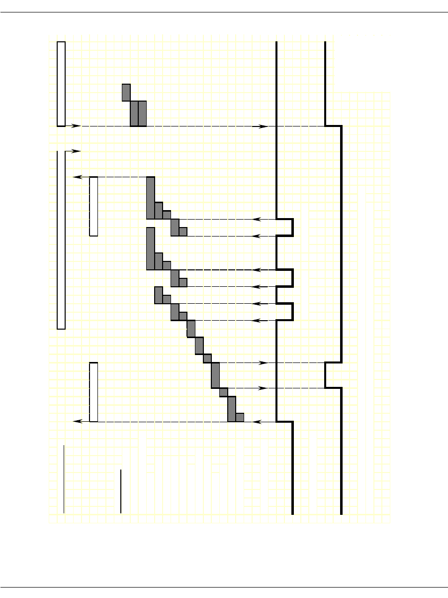
Wink Start & Delay Dial Signaling
November 2009 278
Figure 25. Wink Start and Delay Dial – Incoming Call Timing
IISDN SMI MESSAGES: L4L3mALERTING_REQUEST or L4L3mPROGRESS_REQUEST L4L3mCONNECT_REQUEST
L3L4mPRE_SEIZE L3L4mSETUP_IND
IISDN TIMERS:
hooktimer_onhook_rls
modified_in_rls_timer
hooktimer_onhk_mod_in_rls
critical_time
r
hooktimer_maxmake
hooktimer_minmake
hooktimer_maxbrea
k
hooktimer_minbreak
first_indigit_timer
dptimer_immed_dela
y
dptimer_post_wink
dptimer_wink
dptimer_prewink
delayed_wink_timer
hooktimer_offhook_inseize
RECEIVE HOOKSWITCH:
TRANSMIT HOOKSWITCH:
NOTE: This diagram is designed to give the reader a general understanding of the sequence of events for this robbed
bit protocol over time. The timers and spacing on this graph are not proportional to the actual events that occur. Revised 10-Nov-9
8
Revision 1.
3
DP Digit "2" DP Digit "1"
RECEIVED
TRANSMITTED
Revised
20-Oct-03
Rev 1.4

Wink Start & Delay Dial Signaling
November 2009 279
Outgoing Call Processing
During an outgoing call, the host receives an L3L4mPROGRESS in
response to the L4L3mCALL_REQUEST to start the call. The host
then receives an L3L4mSEIZE_COMP message if send_seize_comp_
event = 1 in the IISDN_ROBBED_BIT_DATA structure. This
message is sent when the module detects a wink from the network,
indicating the network is ready to receive digits. After the digits are
transmitted, the module waits for answer supervision from the
network (indicating the far end has gone off hook) or for an answer
timer to expire (if timed_answer_supervision = 1). When answer
supervision is received or the timer expires, the host receives an
L3L4mCONNECT indicating the call is connected.
Figure 26 shows how the module makes an outgoing call over a wink
start or delay dial trunk.
Call Teardown Processing
For an incoming call teardown, refer to Figure 46 on page 314 at the
end of this section; for an outgoing call teardown, refer to Figure 47
on page 315 at the end of this section.
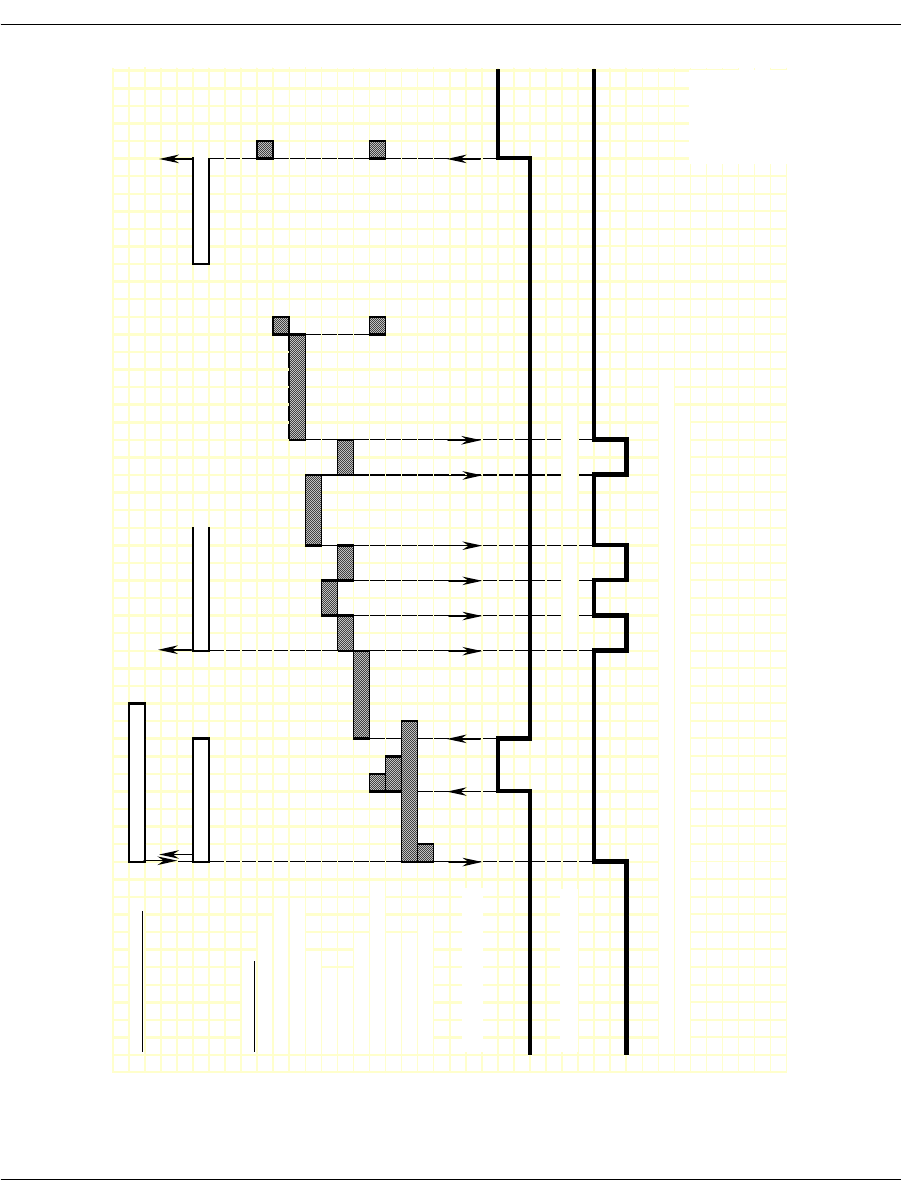
Wink Start & Delay Dial Signaling
November 2009 280
Figure 26. Wink Start and Delay Dial – Outgoing Call Timing
IISDN SMI MESSAGES: L4L3mCALL_REQUEST
L3L4mPROGRESS L3L4mSEIZE_COMP L3L4mCONNECT
IISDN TIMERS:
modified_out_rls_timer
hooktimer_offhook_answer
dptimer_end_dial_pause
dptimer_interdigit
dptimer_make
dptimer_break
fixed_pause_timer
hooktimer_onhk_mod_out_rls
hooktimer_min_wink
outseize_ack_timer
glare_detection_timer
RECEIVE HOOKSWITCH:
TRANSMIT HOOKSWITCH:
NOTE: This diagram is designed to give the reader a general understanding of the sequence of events for this robbed
bit protocol over time. The timers and spacing on this graph are not proportional to the actual events that occur.
Revised 10-Nov-
9
Revision 1
DP Digit "2" DP Digit "1"
RECEIVED
TRANSMITTED
Revised
20-Oct-03
Rev 1.4

Wink Start with Feature Group B & D
November 2009 281
Wink Start with Feature Group B & D
To configure a Brooktrout module for wink start with Feature Group
B and D signaling, the host must issue an L4L3mENABLE_CAS
with an IISDN_ROBBED_BIT_DATA structure that contains the
following settings:
send_glare_err_event = 0 (not used for wink start)
in_trunk_type = IISDNttWINK_START (the default value)
out_trunk_type = IISDNttWINK_START (the default value)
fgb_fgd_mode = 1 (enabling Feature Group B and D)
The remaining settings are described in the context of incoming and
outgoing calls in the subsections that follow.
Incoming Call Processing
During an incoming call, the host receives an L3L4mPRE_SEIZE
message if send_preseize_event = 1 in the IISDN_ROBBED_BIT_
DATA structure. This message is sent when the module detects an
incoming seizure (off hook). The module automatically responds to
the seizure by sending a wink, indicating it is ready to receive digits.
The maximum number of digits the module expects to receive must
be specified in the max_incoming_digit_count field. The digits are
reported to the host in an L3L4mSETUP_IND message.
To acknowledge the receipt of digits, the host must issue an
L4L3mTX_WINK message to send another wink to the network. To
answer the call, the host must issue an L4L3mCONNECT_
REQUEST message.
Figure 27 shows how a Brooktrout module processes an incoming
Feature Group B and D call received over a wink start trunk.
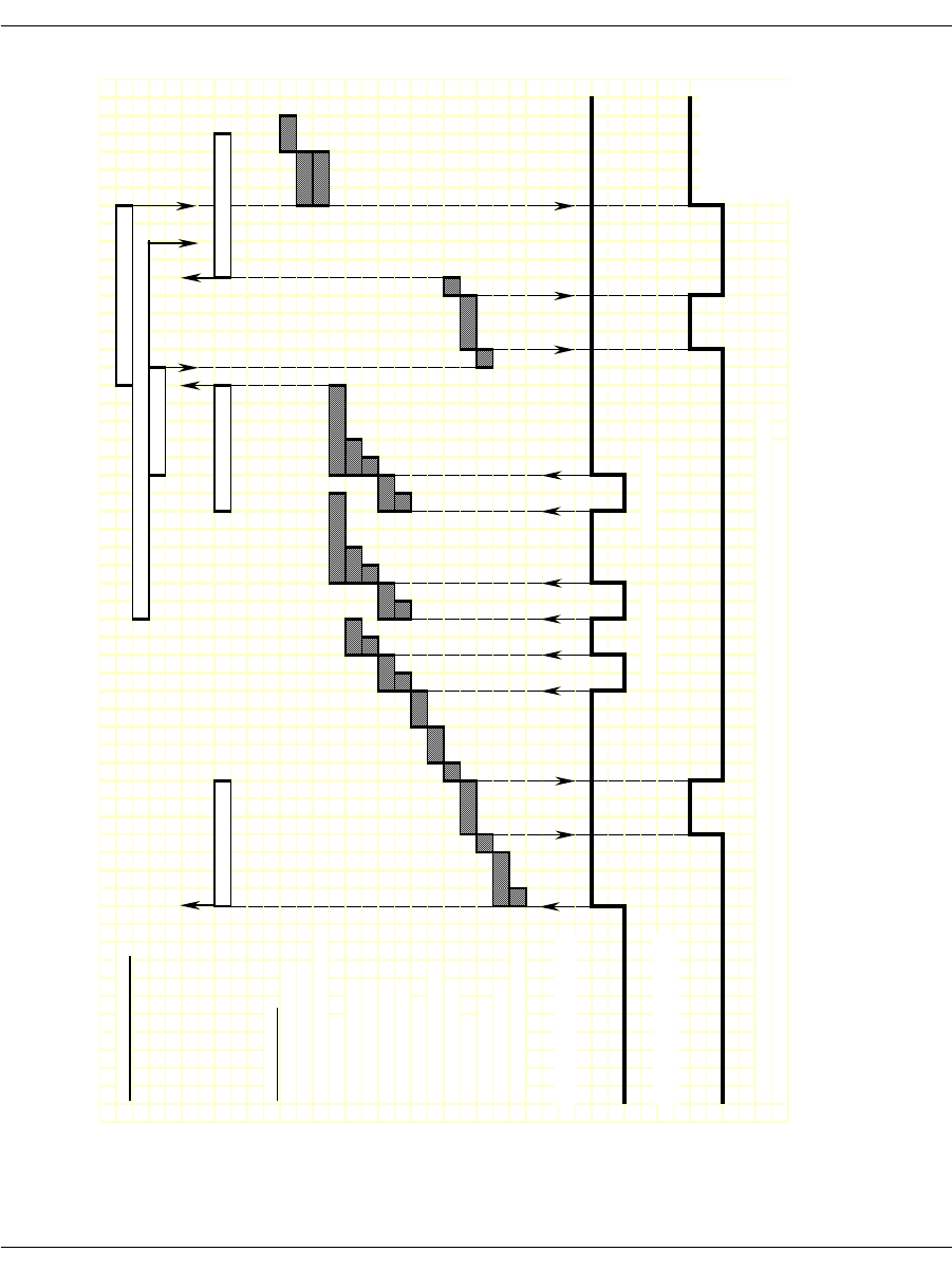
Wink Start with Feature Group B & D
November 2009 282
Figure 27. Wink Start with Feature Group B&D - Incoming Call
Timing Diagram
IISDN SMI MESSAGES: L4L3mCONNECT_REQUEST
L4L3mALERTING_REQUEST or L4L3mPROGRESS_REQUEST
L4L3mTX_WINK
L3L4mPRE_SEIZE L3L4mSETUP_IND L3L4mTXWINK_END
IISDN TIMERS:
hooktimer_onhook_rls
modified_in_rls_timer
hooktimer_onhk_mod_in_rls
critical_time
r
hooktimer_maxmake
hooktimer_minmake
hooktimer_maxbreak
hooktimer_minbreak
first_indigit_time
r
dptimer_immed_delay
dptimer_post_wink
dptimer_wink
dptimer_prewink
delayed_wink_time
r
hooktimer_offhook_inseize
RECEIVE HOOKSWITCH:
TRANSMIT HOOKSWITCH:
Revised 10-Nov-98
NOTE: This diagram is designed to give the reader a general understanding of the sequence of events for this robbed Revision 1.3
bit protocol over time. The timers and spacing on this graph are not proportional to the actual events that occur.
DP Digit "2" DP Digit "1"
RECEIVED
TRANSMITTED
Revised
20-Oct-03
Rev 1.4

Wink Start with Feature Group B & D
November 2009 283
Outgoing Call Processing
The host receives an L3L4mPROGRESS in response to the
L4L3mCALL_REQUEST to start the call. The host then receives an
L3L4mRX_WINK message when the module detects a wink from the
network. The module waits a period of time (determined by the fixed
pause timer) before sending digits. When the timer expires, the host
receives an L3L4mSEIZE_COMP message if send_seize_comp_
event = 1 in the IISDN_ROBBED_BIT_DATA structure.
Call Teardown Processing
For an incoming call teardown, refer to Figure 46 at the end of this
section; for an outgoing call teardown, refer to Figure 47 at the end of
this section.
Wink start with Feature B and D is designed to support transmitting
digits other than dial pulse digits. If called_party_digits = 0 in the
L4L3mCALL_REQUEST that started the call, the module waits in
outdialing state indefinitely. During that time, another device
connected to the Brooktrout module over the TDM bus (such as a
digital tone generator) is used to outpulse digits to the network.
When that device is finished transmitting, the host must issue an
L4L3mEND_DIAL message to make the module continue call
processing.
After the digits are transmitted, the network acknowledges their
receipt by sending a wink to the module. The host receives an
L3L4mRX_WINK when this wink is detected. The module then
waits for answer supervision from the network (indicating the far
end has gone off hook) or for an answer timer to expire (if timed_
answer_supervision = 1). When answer supervision is received or the
timer expires, the host receives an L3L4mCONNECT indicating the
call is connected.
Figure 28 shows how the module makes an outgoing Feature Group
B/D call over a wink start trunk.
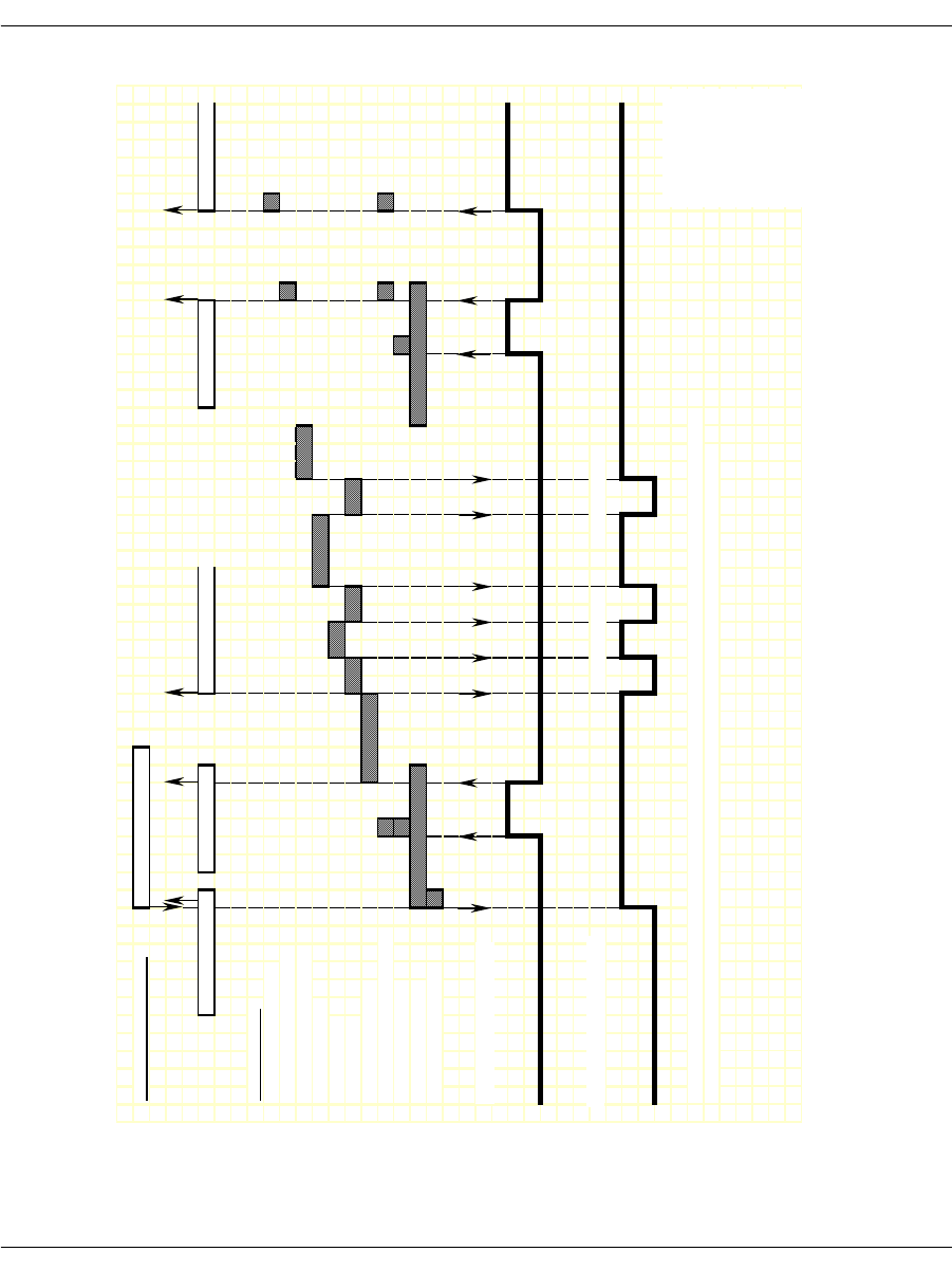
Wink Start with Feature Group B & D
November 2009 284
Figure 28. Wink Start with Feature Group B&D - Outgoing Call
Timing Diagram
IISDN SMI MESSAGES: L4L3mCALL_REQUEST
L3L4mPROGRESS L3L4mRX_WINK L3L4mSEIZE_COMP L3L4mRX_WINK L3L4mCONNECT
IISDN TIMERS:
modified_out_rls_time
r
hooktimer_offhook_answe
r
dptimer_end_dial_pause
dptimer_interdigit
dptimer_make
dptimer_break
fixed_pause_time
r
hooktimer_onhk_mod_out_rls
hooktimer_min_wink
outseize_ack_time
r
glare_detection_time
r
RECEIVE HOOKSWITCH:
TRANSMIT HOOKSWITCH:
NOTE: This diagram is designed to give the reader a general understanding of the sequence of events for this robbed
bit protocol over time. The timers and spacing on this graph are not proportional to the actual events that occur.
Revised 10-Nov-98
Revision 1.3
DP Digit "2" DP Digit "1"
RECEIVED
TRANSMITTED
Revised
20-Oct-03
Rev 1.4

Immediate Start/Fixed Pause Signaling
November 2009 285
Immediate Start/Fixed Pause Signaling
Immediate Start signaling applies to incoming calls only; Fixed
Pause signaling applies to outgoing calls only. Since these signaling
types functionally complement each other, they are handled together
by Brooktrout modules. The exact protocol to be used for a call is
automatically selected depending on whether an incoming or
outgoing call is being handled. To avoid confusion, the symbolic
constants used to select these two protocols, IISDNttIMMEDIATE_
DIAL and IISDNttFIXED_PAUSE, are set to the same value.
To configure a Brooktrout module for immediate start and fixed
pause mode signaling, the host must issue an L4L3mENABLE_CAS
with an IISDN_ROBBED_BIT_DATA structure that contains the
following settings:
send_glare_err_event = 0 (not used)
in_trunk_type = IISDNttIMMEDIATE_DIAL or
IISDNttFIXED_PAUSE
out_trunk_type = IISDNttIMMEDIATE_DIAL or
IISDNttFIXED_PAUSE
fgb_fgd_mode = 0 (not used)
The remaining settings are described in the context of incoming and
outgoing calls in the subsections that follow.
Incoming Call Processing (Immediate Start)
During an incoming call, the host receives an L3L4mPRE_SEIZE
message if send_preseize_event = 1 in the IISDN_ROBBED_BIT_
DATA structure. This message is sent when the module detects an
incoming seizure (off hook). The module then collects dial pulse
digits from the network; the maximum number of digits the module
expects to receive must be specified in the max_incoming_digit_
count field. The digits are reported to the host in an L3L4mSETUP_
IND message. To answer the call, the host must issue an
L4L3mCONNECT_REQUEST message.
Figure 29 shows how a Brooktrout module processes an incoming
call received over an immediate start trunk.
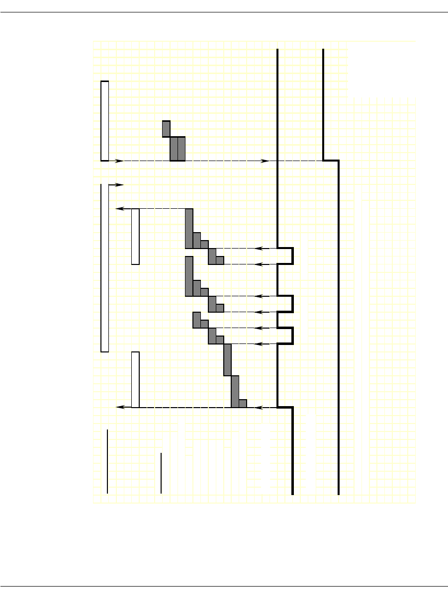
Immediate Start/Fixed Pause Signaling
November 2009 286
Figure 29. Immediate Start – Incoming Call Timing Diagram
IISDN SMI MESSAGES: L4L3mALERTING_REQUEST or L4L3mPROGRESS_REQUEST L4L3mCONNECT_REQUEST
L3L4mPRE_SEIZE L3L4mSETUP_IND
IISDN TIMERS:
hooktimer_onhook_rls
modified_in_rls_timer
hooktimer_onhk_mod_in_rls
critical_timer
hooktimer_maxmake
hooktimer_minmake
hooktimer_maxbreak
hooktimer_minbreak
first_indigit_time
r
dptimer_immed_dela
y
hooktimer_offhook_inseize
RECEIVE HOOKSWITCH:
TRANSMIT HOOKSWITCH:
NOTE: This diagram is designed to give the reader a general understanding of the sequence of events for this robbed
bit protocol over time. The timers and spacing on this graph are not proportional to the actual events that occur.
Revised 10-Nov-98
Revision 1.3
DP Digit "2" DP Digit "1"
RECEIVED
TRANSMITTED
Revised
20-Oct-03
Rev 1.4

Immediate Start/Fixed Pause Signaling
November 2009 287
Outgoing Call Processing (Fixed Pause Mode)
During an outgoing call, the host receives an L3L4mPROGRESS in
response to the L4L3mCALL_REQUEST to start the call. The
module waits a period of time (determined by the fixed pause timer)
before sending digits. When the timer expires, the host receives an
L3L4mSEIZE_COMP message if send_seize_comp_event = 1 in the
IISDN_ROBBED_BIT_DATA structure. After transmitting digits,
the module waits for answer supervision from the network
(indicating the far end has gone off hook) or for an answer timer to
expire (if timed_answer_supervision = 1). When answer supervision
is received or the timer expires, the host receives an
L3L4mCONNECT indicating the call is connected.
Figure 30 shows how the module makes an outgoing call over a fixed
pause mode trunk.
Call Teardown Processing
For an incoming call teardown, refer to Figure 46 at the end of this
section; for an outgoing call teardown, refer to Figure 47 at the end of
this section.
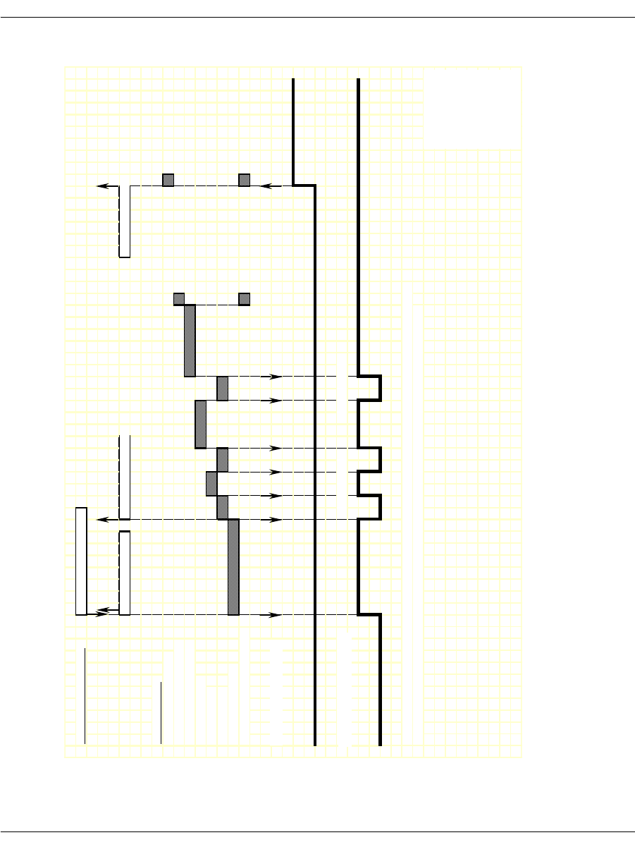
Immediate Start/Fixed Pause Signaling
November 2009 288
Figure 30. Fixed Pause – Outgoing Call Timing Diagram
IISDN SMI MESSAGES: L4L3mCALL_REQUEST
L3L4mPROGRESS L3L4mSEIZE_COMP L3L4mCONNECT
IISDN TIMERS:
modified_out_rls_time
r
hooktimer_offhook_answe
r
dptimer_end_dial_pause
dptimer_interdigit
dptimer_make
dptimer_break
fixed_pause_time
r
hooktimer_onhk_mod_out_rls
RECEIVE HOOKSWITCH:
TRANSMIT HOOKSWITCH:
NOTE: This diagram is designed to give the reader a general understanding of the sequence of events for this robbed
bit protocol over time. The timers and spacing on this graph are not proportional to the actual events that occur.
Revised 10-Nov-98
Revision 1.3
DP Digit "2" DP Digit "1"
RECEIVED
TRANSMITTED
Revised
20-Oct-03
Rev 1.4

Ground Start Signaling
November 2009 289
Ground Start Signaling
Brooktrout modules support two types of ground start signaling:
Foreign Exchange - Office (FXO)
Foreign Exchange - Subscriber (FXS)
When operating in FXO mode, the module assumes the far end of the
connection is an FXS termination. When operating in FXS mode, the
module assumes the far end is an FXO termination. The timing
diagrams on the pages that follow use the labels “FXO” or “FXS”
rather than “Rx” or “Tx” for hookswitch states to illustrate this point.
FXO Ground Start
To configure a Brooktrout module for FXO ground start signaling,
the host must issue an L4L3mENABLE_B_CHANNEL with an
IISDN_ROBBED_BIT_DATA structure that contains the following
settings:
in_trunk_type = IISDNttFXO_GDSTART
out_trunk_type = IISDNttFXO_GDSTART
timed_answer_supervision = 1 (timer expiration indicates far
end answer)
fgb_fgd_mode = 0 (not used)
The remaining settings are described in the context of incoming and
outgoing calls in the subsections that follow.
Incoming Call Processing
During an incoming call, the host receives an L3L4mPRE_SEIZE
message if send_preseize_event = 1 in the IISDN_ROBBED_BIT_
DATA structure. This message is sent when the module detects ring
ground at the far end (FXS end). The module then collects dial pulse
digits from the network; the maximum number of digits the module
expects to receive must be specified in the max_incoming_digit_
count field. The digits are reported to the host in an L3L4mSETUP_
IND message. To answer the call, the host must issue an
L4L3mCONNECT_REQUEST message.

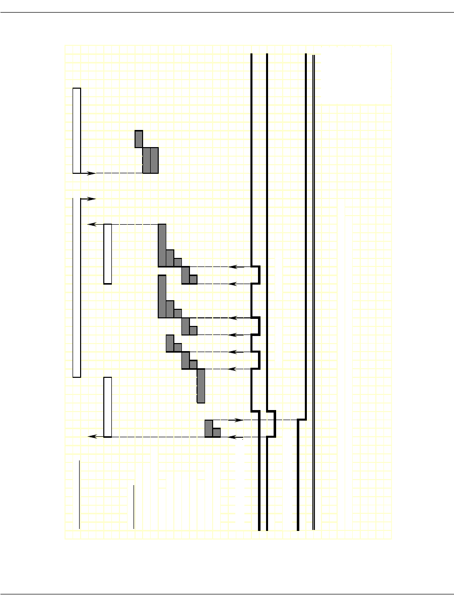
Ground Start Signaling
November 2009 291
Figure 31. FXO Ground Start – Incoming Call Timing Diagram
IISDN SMI MESSAGES: L4L3mALERTING_REQUEST or L4L3mPROGRESS_REQUEST L4L3mCONNECT_REQUEST
L3L4mPRE_SEIZE L3L4mSETUP_IND
IISDN TIMERS:
hooktimer_onhook_rls
modified_in_rls_time
r
hooktimer_onhk_mod_in_rls
critical_time
r
hooktimer_maxmake
hooktimer_minmake
hooktimer_maxbreak
hooktimer_minbreak
first_indigit_time
r
dptimer_immed_dela
y
hooktimer_offhook_inseize
RECEIVE HOOKSWITCH, FXS:
A
Bi
t
B
Bi
t
TRANSMIT HOOKSWITCH, FXO:
A
Bi
t
B Bit (ignored)
NOTE: This diagram is designed to give the reader a general understanding of the sequence of events for this robbed
bit protocol over time. The timers and spacing on this graph are not proportional to the actual events that occur.
Revised 10-Nov-98
Revision 1.3
DP Digit "2" DP Digit "1"
RECEIVED BITS,
TRANSMITTED
Revised
20-Oct-03
Rev 1.4

Ground Start Signaling
November 2009 292
Outgoing Call Processing
If send_glare_err_event = 0 in the IISDN_ROBBED_BIT_DATA
structure, the host receives an L3L4mERROR message containing
the value L3L4errGLARE if the outgoing call attempt fails due to
glare. Glare occurs when the module attempts to make an outgoing
call on a channel at the same time an incoming call arrives on the
channel. The call attempt fails because the network always wins
channel contention.
During an outgoing call, the host receives an L3L4mPROGRESS in
response to the L4L3mCALL_REQUEST to start the call. The host
then receives an L3L4mSEIZE_COMP message if send_seize_comp_
event = 1 in the IISDN_ROBBED_BIT_DATA structure. This
message is sent after the fixed pause timer expires. No digits are
collected in FXO ground start mode; the module simply waits for an
answer timer to expire (if timed_answer_supervision = 1). When the
timer expires, the host receives an L3L4mCONNECT indicating the
call is connected.
Figure 32 shows how the module makes an outgoing call over an
FXO ground start trunk.
Call Teardown Processing
For an incoming call teardown, refer to Figure 33; for an outgoing
call teardown, refer to Figure 34.
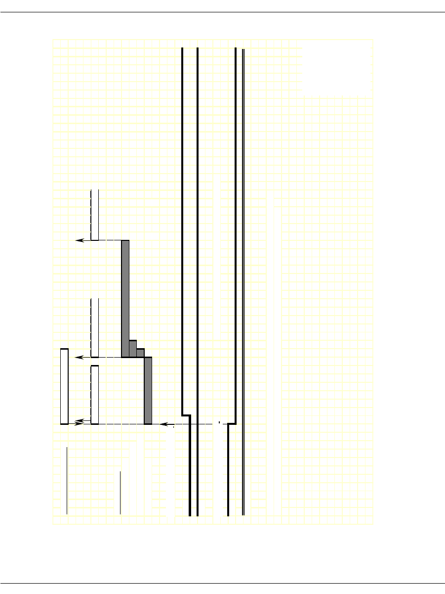
Ground Start Signaling
November 2009 293
Figure 32. FXO Ground Start – Outgoing Call Timing Diagram
IISDN SMI MESSAGES: L4L3mCALL_REQUEST
L3L4mPROGRESS L3L4mSEIZE_COMP L3L4mCONNECT
IISDN TIMERS:
fake_answer_time
r
hooktimer_offhook_answe
r
hooktimer_onhk_mod_out_rls
fixed_pause_time
r
RECEIVE HOOKSWITCH, FXS:
A Bit
B Bit
TRANSMIT HOOKSWITCH, FXO: NOTE: No digits are collected on the far end in this mode.
A Bit
B Bit (ignored)
NOTE: This diagram is designed to give the reader a general understanding of the sequence of events for this robbed
bit protocol over time. The timers and spacing on this graph are not proportional to the actual events that occur.
Revised 10-Nov-98
Revision 1.3
RECEIVED BITS,
TRANSMITTED
Revised
20-Oct-03
Rev 1.4
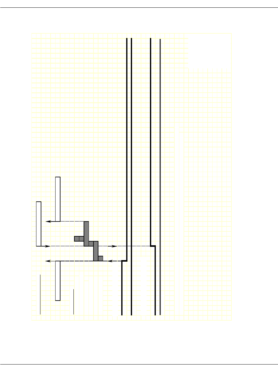
Ground Start Signaling
November 2009 294
Figure 33. FXO Ground Start - Incoming Clear Timing Diagram
IISDN SMI MESSAGES: L4L3mCLEAR_REQUEST
L3L4mDISCONNECT L3L4mCLEAR_REQUEST
IISDN TIMERS:
hooktimer_onhook_rls
hooktimer_offhook_inseize
guard_interval_timer
ign_insz_post_rls_timer
delayed_onhook_timer
hooktimer_onhook_rls
RECEIVE HOOKSWITCH, FXS:
A Bit
B Bit
TRANSMIT HOOKSWITCH, FXO:
A Bit
B Bit (ignored)
NOTE: This diagram is designed to give the reader a general understanding of the sequence of events for this robbed
bit protocol over time. The timers and spacing on this graph are not proportional to the actual events that occur.
Revised 10-Nov-98
Revision 1.3
RECEIVED BITS,
TRANSMITTED
Revised
20-Oct-03
Rev 1.4
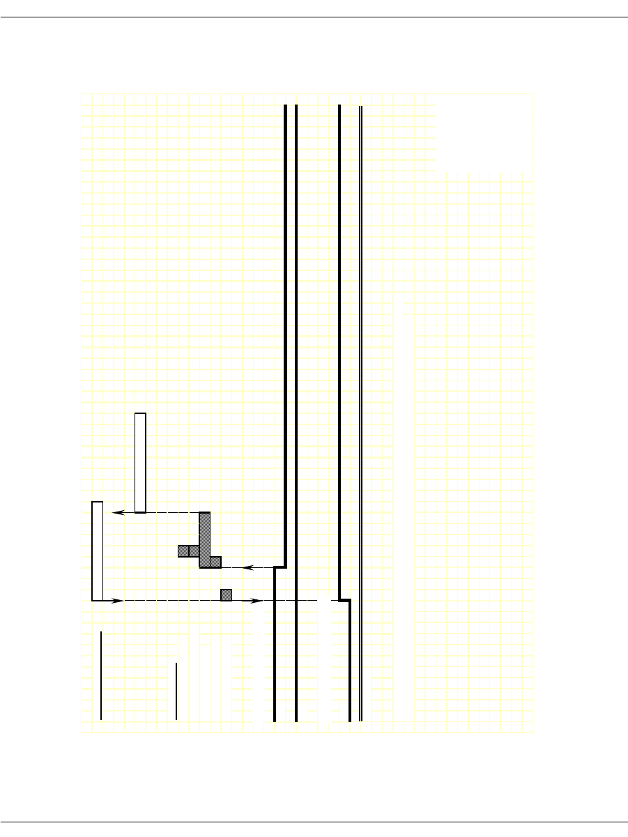
Ground Start Signaling
November 2009 295
Figure 34. FXO Ground Start - Outgoing Clear Timing Diagram
IISDN SMI MESSAGES: L4L3mCLEAR_REQUEST
L3L4mCLEAR_REQUEST
IISDN TIMERS:
hooktimer_onhook_rls
hooktimer_offhook_inseize
guard_interval_timer
ign_insz_post_rls_timer
hooktimer_onhook_rls
RECEIVE HOOKSWITCH, FXS:
A Bit
B Bit
TRANSMIT HOOKSWITCH, FXO:
A Bit
B Bit (ignored)
NOTE: This diagram is designed to give the reader a general understanding of the sequence of events for this robbed
bit protocol over time. The timers and spacing on this graph are not proportional to the actual events that occur.
Revised 10-Nov-98
Revision 1.3
RECEIVED BITS,
TRANSMITTED
Revised
20-Oct-03
Rev 1.4

Ground Start Signaling
November 2009 296
FXS Ground Start
To configure a Brooktrout module for FXS ground start signaling,
the host must issue an L4L3mENABLE_CAS with an IISDN_
ROBBED_BIT_DATA structure that contains the following settings:
in_trunk_type = IISDNtt5ESS_GDSTART
out_trunk_type = IISDNtt5ESS_GDSTART
max_incoming_digit_count = 0 (no digits collected)
timed_answer_supervision = 1 (timer expiration indicates far
end answer)
fgb_fgd_mode = 0 (not used)
The remaining settings are described in the context of incoming and
outgoing calls in the subsections that follow.
Incoming Call Processing
During an incoming call, the host receives an L3L4mPRE_SEIZE
message if send_preseize_event = 1 in the IISDN_ROBBED_BIT_
DATA structure. This message is sent when the module detects an
incoming seizure. No digits are collected in FXS ground start mode;
to answer the call, the host must issue an L4L3mCONNECT_
REQUEST message.
Figure 35 shows how a Brooktrout module processes an incoming
call received over an FXS ground start trunk.
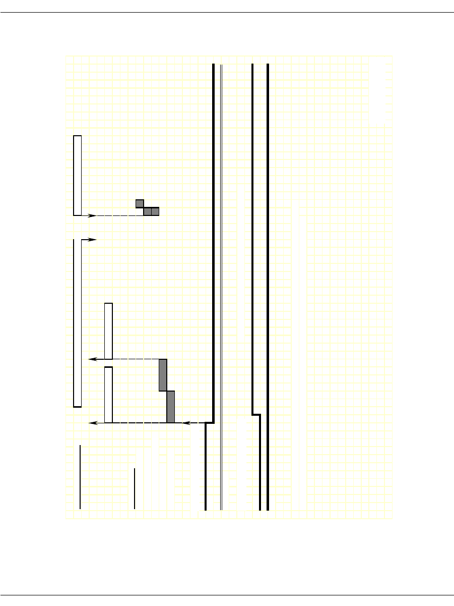
Ground Start Signaling
November 2009 297
Figure 35. FXS Ground Start – Incoming Call Timing Diagram
IISDN SMI MESSAGES: L4L3mALERTING_REQUEST or L4L3mPROGRESS_REQUEST L4L3mCONNECT_REQUEST
L3L4mPRE_SEIZE L3L4mSETUP_IND
IISDN TIMERS:
hooktimer_onhook_rls
modified_in_rls_time
r
hooktimer_onhk_mod_in_rls
first_indigit_time
r
dptimer_immed_dela
y
RECEIVE HOOKSWITCH, FXO:
A Bi
t
B Bit (ignored)
TRANSMIT HOOKSWITCH, FXS: NOTE: No digits are collected on the near end in this mode.
A Bi
t
B Bi
t
NOTE: This diagram is designed to give the reader a general understanding of the sequence of events for this robbed
bit protocol over time. The timers and spacing on this graph are not proportional to the actual events that occur.
Revised 10-Nov-98
Revision 1.3
RECEIVED BITS,
TRANSMITTED
Revised

Ground Start Signaling
November 2009 298
Outgoing Call Processing
If send_glare_err_event = 0 in the IISDN_ROBBED_BIT_DATA
structure, the host receives an L3L4mERROR message containing
the value L3L4errGLARE if the outgoing call attempt fails due to
glare. Glare occurs when the module attempts to make an outgoing
call on a channel at the same time an incoming call arrives on the
channel. The call attempt fails because the network always wins
channel contention.
During an outgoing call, the host receives an L3L4mPROGRESS in
response to the L4L3mCALL_REQUEST to start the call. The
module starts the fixed pause timer when it detects tip ground at the
far end (FXO end). When the timer expires, the host receives an
L3L4mSEIZE_COMP message if send_seize_comp_event = 1 in the
IISDN_ROBBED_BIT_DATA structure.
FXS ground start supports transmitting digits other than dial pulse
digits. If called_party_digits = 0 in the L4L3mCALL_REQUEST that
started the call, the module waits in outdialing state indefinitely.
During that time, another device connected to the Brooktrout
module over the TDM bus (such as a digital tone generator) is used
to outpulse digits to the network.
After the digits are transmitted, the module waits for an answer
timer to expire (if timed_answer_supervision = 1). When the timer
expires, the host receives an L3L4mCONNECT indicating the call is
connected.
Figure 36 shows how the module makes an outgoing call over an
FXS ground start trunk.
Call Teardown Processing
For an incoming call teardown, refer to Figure 37; for an outgoing
call teardown, refer to Figure 38.
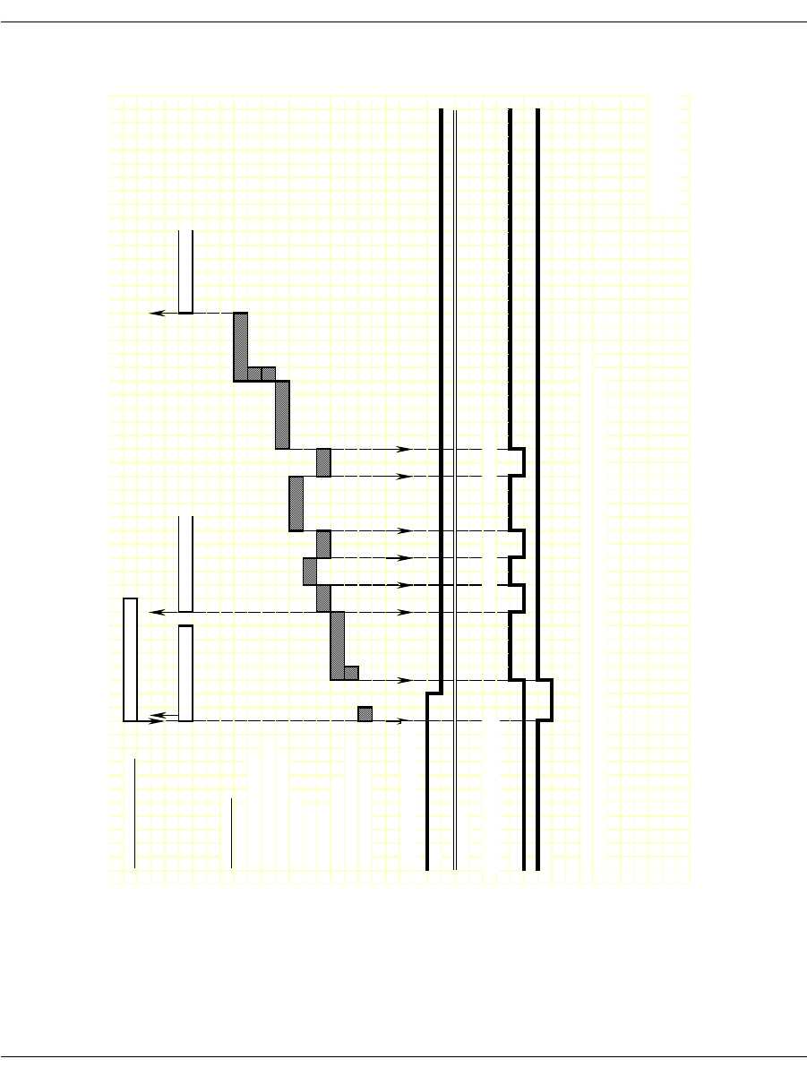
Ground Start Signaling
November 2009 299
Figure 36. FXS Ground Start – Outgoing Call Timing Diagram
IISDN SMI MESSAGES: L4L3mCALL_REQUEST
L3L4mPROGRESS L3L4mSEIZE_COMP L3L4mCONNECT
IISDN TIMERS:
answer_time
r
hooktimer_offhook_answe
r
hooktimer_onhk_mod_out_rls
dptimer_end_dial_pause
dptimer_interdigit
dptimer_make
dptimer_break
fixed_pause_timer
hooktimer_onhk_mod_out_rls
glare_detection_time
r
RECEIVE HOOKSWITCH, FXO:
A
Bit
B Bit (ignored)
TRANSMIT HOOKSWITCH, FXS:
A Bi
t
B Bi
t
NOTE: This diagram is designed to give the reader a general understanding of the sequence of events for this robbed
bit protocol over time. The timers and spacing on this graph are not proportional to the actual events that occur.
Revised 10-Nov-98
Revision 1.3
DP Digit "2" DP Digit "1"
RECEIVED
TRANSMITTED
Revised
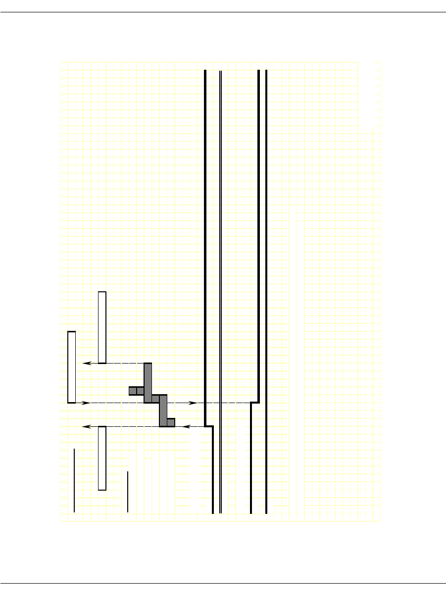
Ground Start Signaling
November 2009 300
Figure 37. FXS Ground Start - Incoming Clear Timing Diagram
IISDN SMI MESSAGES: L4L3mCLEAR_REQUEST
L3L4mDISCONNECT L3L4mCLEAR_REQUEST
IISDN TIMERS:
hooktimer_onhook_rls
hooktimer_offhook_inseize
guard_interval_timer
ign_insz_post_rls_timer
delayed_onhook_timer
hooktimer_onhook_rls
RECEIVE HOOKSWITCH, FXO:
A
Bi
t
B Bit (ignored)
TRANSMIT HOOKSWITCH, FXS:
A
Bi
t
B Bit
NOTE: This diagram is designed to give the reader a general understanding of the sequence of events for this robbed
bit protocol over time. The timers and spacing on this graph are not proportional to the actual events that occur.
Revised 10-Nov-98
Revision 1.3
RECEIVED BITS,
TRANSMITTED
Revised
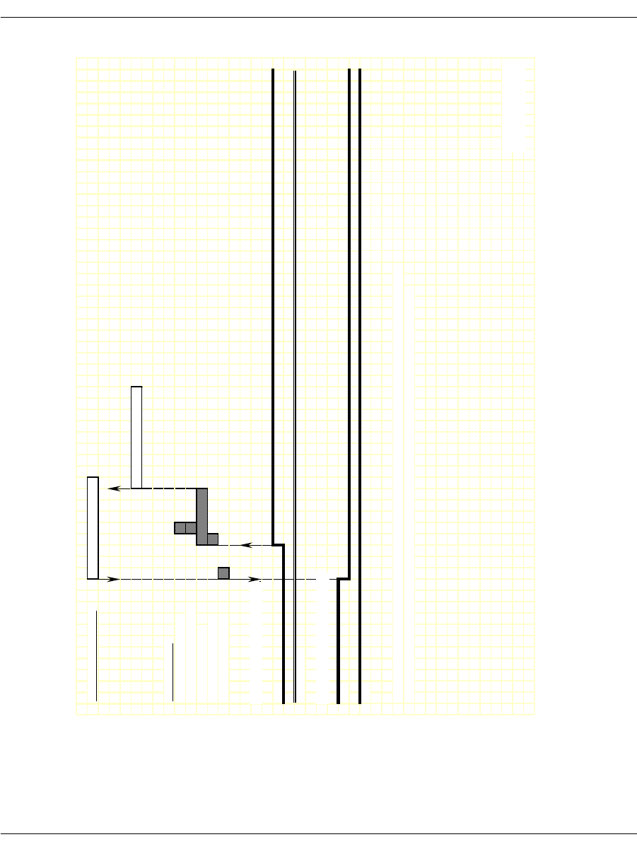
Ground Start Signaling
November 2009 301
Figure 38. FXS Ground Start - Outgoing Clear Timing Diagram
IISDN SMI MESSAGES: L4L3mCLEAR_REQUEST
L3L4mCLEAR_REQUEST
IISDN TIMERS:
hooktimer_onhook_rls
hooktimer_offhook_inseize
guard_interval_timer
ign_insz_post_rls_timer
hooktimer_onhook_rls
RECEIVE HOOKSWITCH, FXO:
A Bit
B Bit (ignored)
TRANSMIT HOOKSWITCH, FXS:
A Bit
B Bit
NOTE: This diagram is designed to give the reader a general understanding of the sequence of events for this robbed
bit protocol over time. The timers and spacing on this graph are not proportional to the actual events that occur.
Revised 10-Nov-98
Revision 1.3
RECEIVED BITS,
TRANSMITTED
Revised

Loop Start Signaling
November 2009 302
Loop Start Signaling
Brooktrout modules support two types of loop start signaling:
FXO Loop Start
FXS Loop Start
When operating in FXO mode, the module assumes the far end of the
connection is an FXS termination. When operating in FXS mode, the
module assumes the far end is an FXO termination.
FXS Loop Start is the protocol used for Brooktrout's analog modules.
The sequence of events and timings is the same for both analog or
digital line interfaces.
The timing diagrams in this section show the Receive and Transmit
Signaling Bits in reference to the digital signaling mode. The analog
signals are a direct mapping of the signaling bits.
In the FXS diagrams, the electric signals sent by the station are
represented in bit A: loop current presence (off-hook) is represented
by setting bit A high (one); absence (on-hook) by bit A low (zero). Bit
B does not change. The signals received by the station, ring signal
and loop current feed (battery), are represented using both A and B
bits: loop current feed is represented by setting bit A low (zero);
absence by bit A high (one). Presence of ring signal is represented by
setting bit B low (zero); absence by bit B high (one).
The FXO diagrams are the mirror-image of the FXS diagrams. The
signals sent by the module (FXO) toward the network (FXS) are the
same that the station (FXS) received from the network (FXO) on the
FXS diagrams.

Loop Start Signaling
November 2009 303
FXO Loop Start
To configure a Brooktrout module for FXO loop start signaling, the
host must issue an L4L3mENABLE_CAS with an IISDN_ROBBED_
BIT_DATA structure that contains the following settings:
send_glare_err_event = 0 (not used for loop start)
in_trunk_type = IISDNttFXO_LPSTART
out_trunk_type = IISDNttFXO_LPSTART
timed_answer_supervision = 0 (answer supervision required)
fgb_fgd_mode = 0 (not used)
The remaining settings are described in the context of incoming and
outgoing calls in the subsections that follow.
Note: The FXO end of a loop start connection uses the same A and B
bit values for both idle and connected states. Because of this,
the Brooktrout module cannot detect when the FXO end goes
on hook. To idle the channel, the host must detect the presence
of a busy/reorder tone coming from the FXO end and issue an
L4L3mCLEAR_REQUEST to disconnect the call. To ensure
the FXO end returns to an idle state, the host must also reset
the channel by issuing an L4L3mDISABLE_CAS immediately
followed by an L4L3mENABLE_CAS in order to make another
call.

Loop Start Signaling
November 2009 304
Incoming Call Processing
During an incoming call, the host receives an L3L4mPRE_SEIZE
message if send_preseize_event = 1 in the IISDN_ROBBED_BIT_
DATA structure. This message is sent when the module detects an
incoming seize from the far end (FXS end). The module then collects
dial pulse digits from the network; the maximum number of digits
the module expects to receive must be specified in the max_
incoming_digit_count field. The digits are reported to the host in an
L3L4mSETUP_IND message. To answer the call, the host must
issue an L4L3mCONNECT_REQUEST message. Figure 39 shows
how a Brooktrout module processes an incoming call received over
an FXO loop start trunk.
Outgoing Call Processing
During an outgoing call, the host receives an L3L4mPROGRESS in
response to the L4L3mCALL_REQUEST to start the call. The
module automatically transmits a ringing pattern using the B
signaling bit. When the far end goes off hook, the host receives an
L3L4mCONNECT indicating the call is connected.
Figure 40 shows how the module makes an outgoing call over an
FXO ground start trunk.
Call Teardown Processing
For an incoming call teardown, refer to Figure 41; for an outgoing
call teardown, refer to Figure 42.
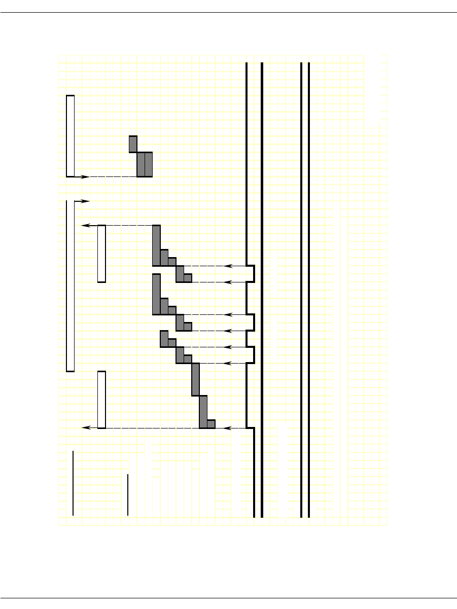
Loop Start Signaling
November 2009 305
Figure 39. FXO Loop Start – Incoming Call Timing Diagram
IISDN SMI MESSAGES: L4L3mALERTING_REQUEST or L4L3mPROGRESS_REQUEST L4L3mCONNECT_REQUEST
L3L4mPRE_SEIZE L3L4mSETUP_IND
IISDN TIMERS:
hooktimer_onhook_rls
modified_in_rls_time
r
hooktimer_onhk_mod_in_rls
critical_time
r
hooktimer_maxmake
hooktimer_minmake
hooktimer_maxbrea
k
hooktimer_minbreak
first_indigit_timer
dptimer_immed_dela
y
hooktimer_offhook_inseize
RECEIVE HOOKSWITCH, FXS:
A
Bi
t
B Bit
TRANSMIT HOOKSWITCH, FXO:
A
Bi
t
B Bit
NOTE: This diagram is designed to give the reader a general understanding of the sequence of events for this robbed
bit protocol over time. The timers and spacing on this graph are not proportional to the actual events that occur.
Revised 10-Nov-98
Revision 1.3
DP Digit "2" DP Digit "1"
RECEIVED BITS,
TRANSMITTED
Revised
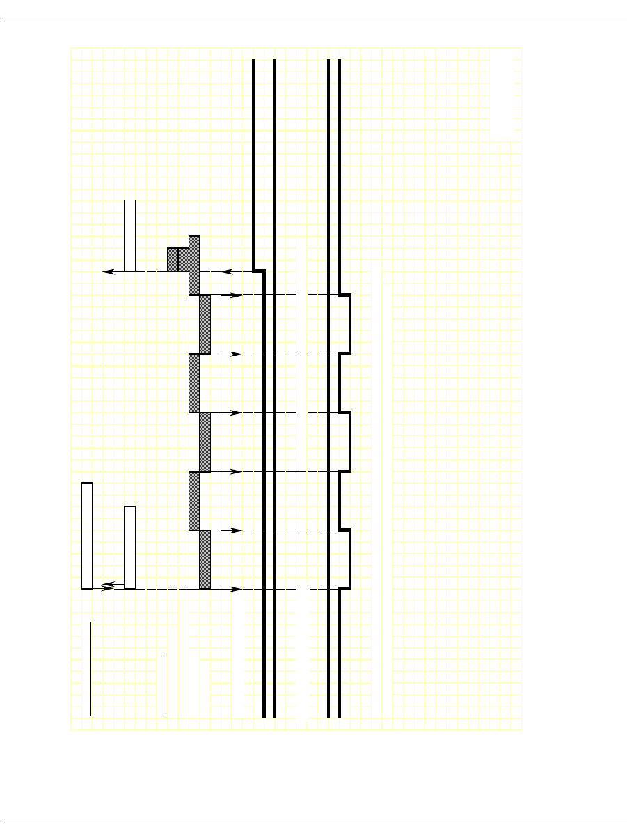
Loop Start Signaling
November 2009 306
Figure 40. FXO Loop Start – Outgoing Call Timing Diagram
IISDN SMI MESSAGES: L4L3mCALL_REQUEST
L3L4mPROGRESS L3L4mCONNECT
IISDN TIMERS:
modified_out_rls_time
r
hooktimer_onhk_mod_out_rls
no_ringing_time
r
ringing_time
r
RECEIVE HOOKSWITCH, FXS:
A Bit
B Bit
TRANSMIT HOOKSWITCH, FXO: NOTE: No digits are collected on the far end in this mode.
A Bit
B Bit
NOTE: This diagram is designed to give the reader a general understanding of the sequence of events for this robbed
bit protocol over time. The timers and spacing on this graph are not proportional to the actual events that occur.
Revised 10-Nov-98
Revision 1.3
TRANSMITTED
RECEIVED BITS,
Revised
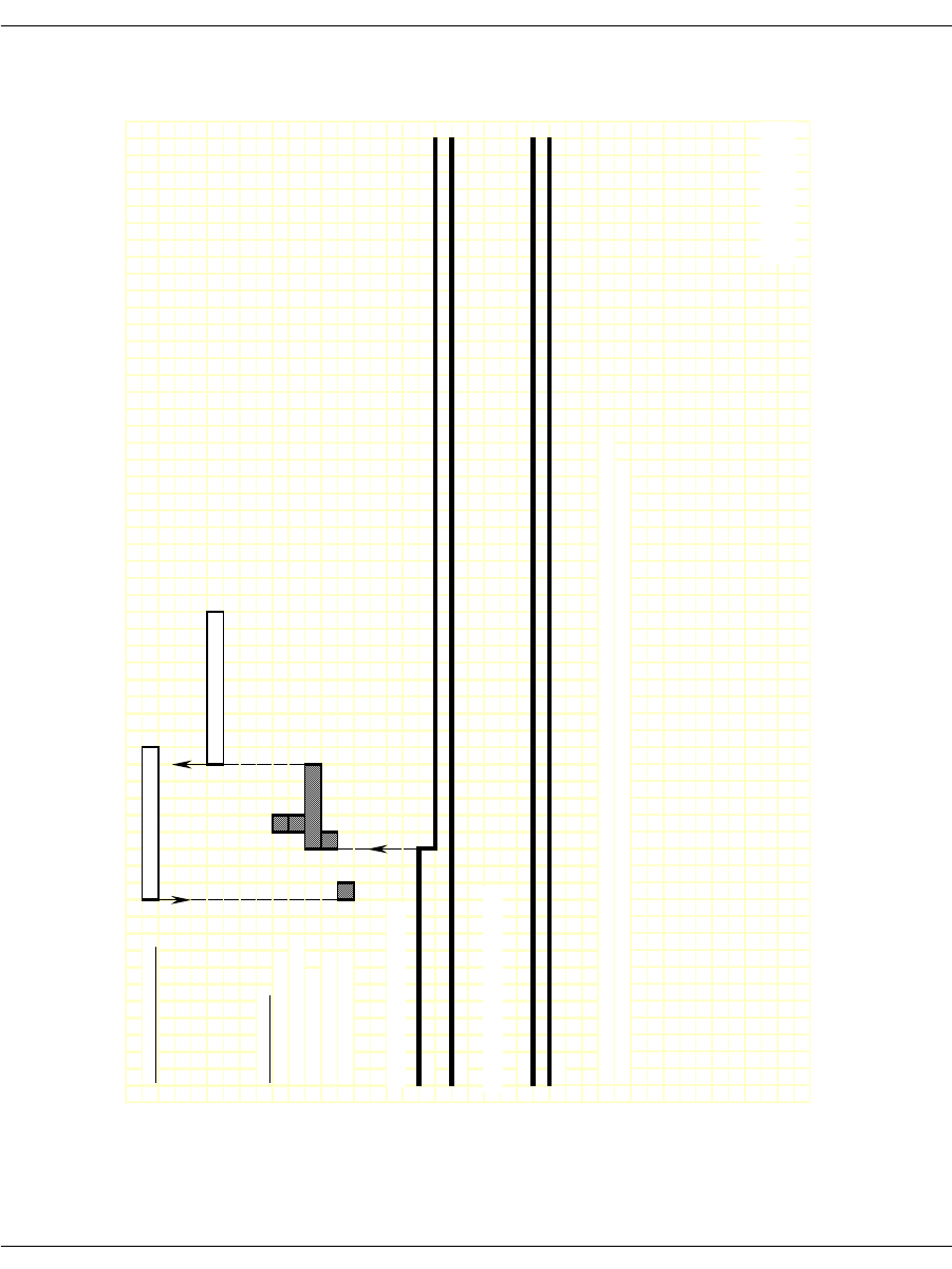
Loop Start Signaling
November 2009 307
Figure 41. FXO Loop Start – Outgoing Clear Timing Diagram
IISDN SMI MESSAGES: L4L3mCLEAR_REQUEST
L3L4mCLEAR_REQUEST
IISDN TIMERS:
hooktimer_onhook_rls
hooktimer_offhook_inseize
guard_interval_timer
ign_insz_post_rls_timer
hooktimer_onhook_rls
RECEIVE HOOKSWITCH, FXS:
A
Bi
t
B Bit
TRANSMIT HOOKSWITCH, FXO:
A
Bi
t
B Bit
NOTE: This diagram is designed to give the reader a general understanding of the sequence of events for this robbed
bit protocol over time. The timers and spacing on this graph are not proportional to the actual events that occur.
Revised 10-Nov-98
Revision 1.3
TRANSMITTED
RECEIVED BITS,
Revised
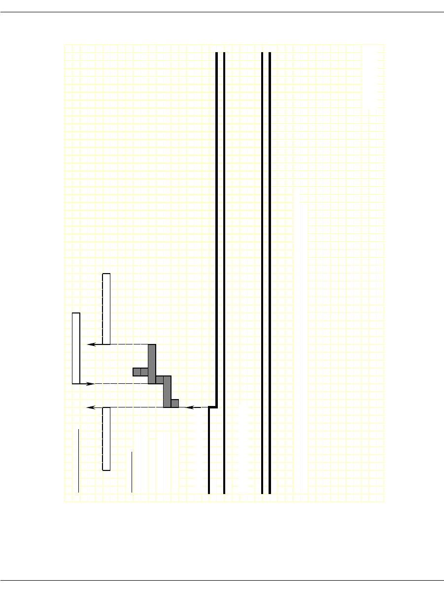
Loop Start Signaling
November 2009 308
Figure 42. FXO Loop Start – Incoming Clear Timing Diagram
IISDN SMI MESSAGES: L4L3mCLEAR_REQUEST
L3L4mDISCONNECT L3L4mCLEAR_REQUEST
IISDN TIMERS:
hooktimer_onhook_rls
hooktimer_offhook_inseize
guard_interval_timer
ign_insz_post_rls_timer
delayed_onhook_timer
hooktimer_onhook_rls
RECEIVE HOOKSWITCH, FXS:
A
Bi
t
B Bit
TRANSMIT HOOKSWITCH, FXO:
A
Bi
t
B Bit
NOTE: This diagram is designed to give the reader a general understanding of the sequence of events for this robbed
bit protocol over time. The timers and spacing on this graph are not proportional to the actual events that occur.
Revised 10-Nov-98
Revision 1.3
RECEIVED BITS,
TRANSMITTED
Revised

Loop Start Signaling
November 2009 309
FXS Loop Start
To configure a Brooktrout module for FXS loop start signaling, the
host must issue an L4L3mENABLE_CAS with an IISDN_ROBBED_
BIT_DATA structure that contains the following settings:
in_trunk_type = IISDNtt5ESS_LPSTART
out_trunk_type = IISDNtt5ESS_LPSTART
max_incoming_digit_count = 0 (no digits collected)
timed_answer_supervision = 1 (timer expiration indicates far
end answer)
fgb_fgd_mode = 0 (not used)
The remaining settings are described in the context of incoming and
outgoing calls in the subsections that follow.
Note: The FXO end of a loop start connection uses the same A and B
bit values for both idle and connected states. Because of this,
the Brooktrout module cannot detect when the FXO end goes
on hook. To idle the channel, the host must detect the lack of
data coming from the FXO end and issue an L4L3mCLEAR_
REQUEST to disconnect the call. To ensure the FXO end
returns to an idle state, the host must also reset the channel
by issuing an L4L3mDISABLE_CAS immediately followed by
an L4L3mENABLE_CAS in order to make another call.
Incoming Call Processing
During an incoming call, the host receives an L3L4mPRE_SEIZE
message if send_preseize_event = 1 in the IISDN_ROBBED_BIT_
DATA structure. This message is sent when the module detects
ringing from the far end (FXO end). No digits are collected in FXS
loop start mode; to answer the call, the host must issue an
L4L3mCONNECT_REQUEST message.
Figure 43 shows how a Brooktrout module processes an incoming
call received over an FXS loop start trunk.
Outgoing Call Processing
During an outgoing call, the host receives an L3L4mPROGRESS in
response to the L4L3mCALL_REQUEST to start the call. The host
then receives an L3L4mSEIZE_COMP message if send_seize_comp_

Loop Start Signaling
November 2009 310
event = 1 in the IISDN_ROBBED_BIT_DATA structure. This
message is sent after the fixed pause timer expires. When the timer
expires, the host receives an L3L4mSEIZE_COMP message if send_
seize_comp_event = 1 in the IISDN_ROBBED_BIT_DATA structure.
FXS ground start supports transmitting digits other than dial pulse
digits. If called_party_digits = 0 in the L4L3mCALL_REQUEST that
started the call, the module waits in outdialing state indefinitely.
During that time, another device connected to the Brooktrout
module over the TDM bus (such as a digital tone generator) is used
to outpulse digits to the network.
After the digits are transmitted, the module waits for an answer
timer to expire (if timed_answer_supervision = 1). When the timer
expires, the host receives an L3L4mCONNECT indicating the call is
connected.
Figure 44 shows how the module makes an outgoing call over an
FXS ground start trunk.
Call Teardown Processing
In this mode, an incoming call teardown cannot be detected; the host
must determine when the call is inactive (that is. no data) and
initiate an outgoing call teardown. For an outgoing call teardown,
refer to Figure 45.
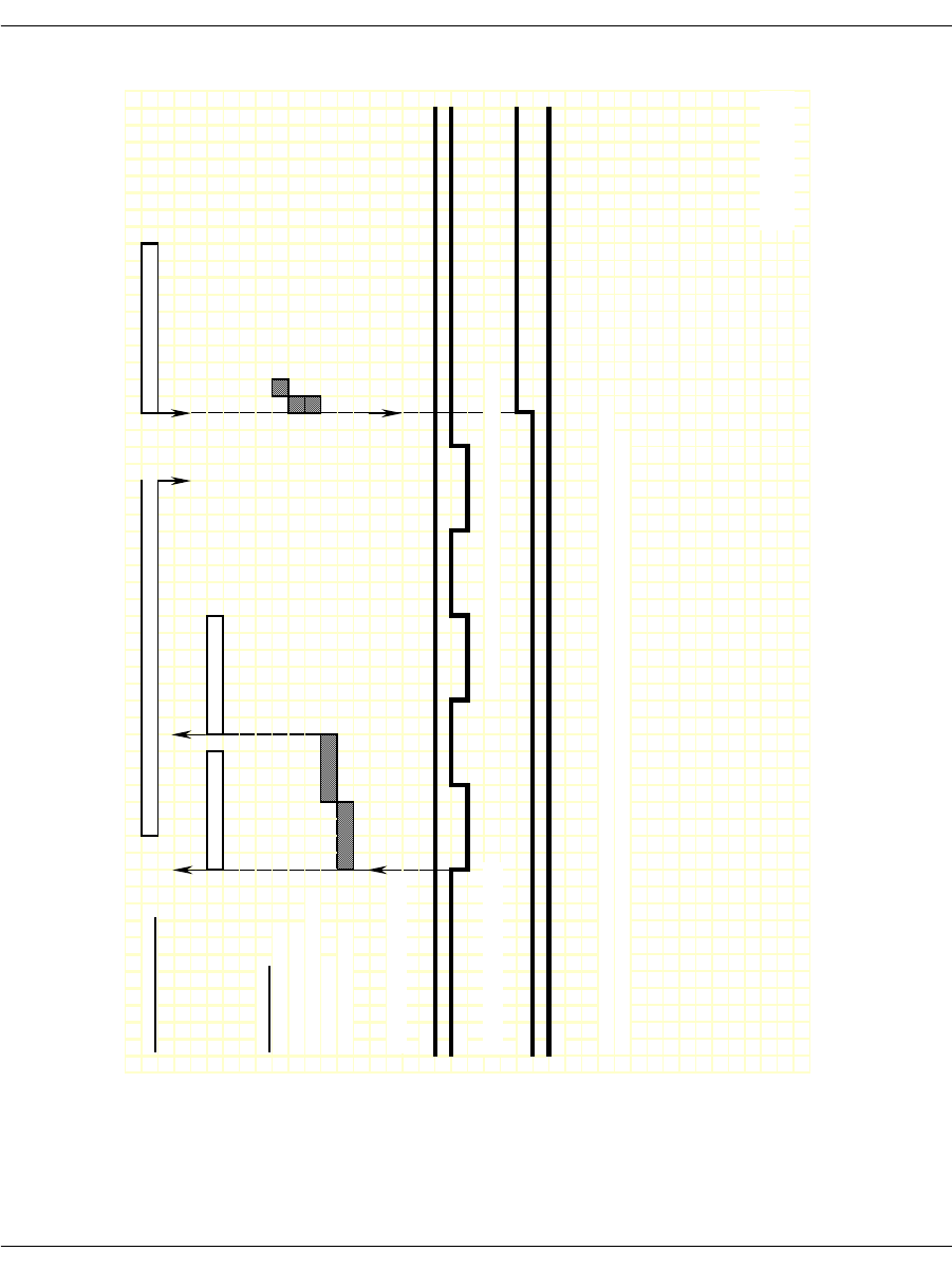
Loop Start Signaling
November 2009 311
Figure 43. FXS Loop Start – Incoming Call Timing Diagram
IISDN SMI MESSAGES: L4L3mALERTING_REQUEST or L4L3mPROGRESS_REQUEST L4L3mCONNECT_REQUEST
L3L4mPRE_SEIZE L3L4mSETUP_IND
IISDN TIMERS:
hooktimer_onhook_rls
modified_in_rls_timer
hooktimer_onhk_mod_in_rls
first_indigit_timer
dptimer_immed_dela
y
RECEIVE HOOKSWITCH, FXO:
A
Bi
t
B
Bi
t
TRANSMIT HOOKSWITCH, FXS: NOTE: No digits are collected on the near end in this mode.
A
Bi
t
B Bit
NOTE: This diagram is designed to give the reader a general understanding of the sequence of events for this robbed
bit protocol over time. The timers and spacing on this graph are not proportional to the actual events that occur.
Revised 10-Nov-98
Revision 1.3
RECEIVED BITS,
TRANSMITTED
Revised
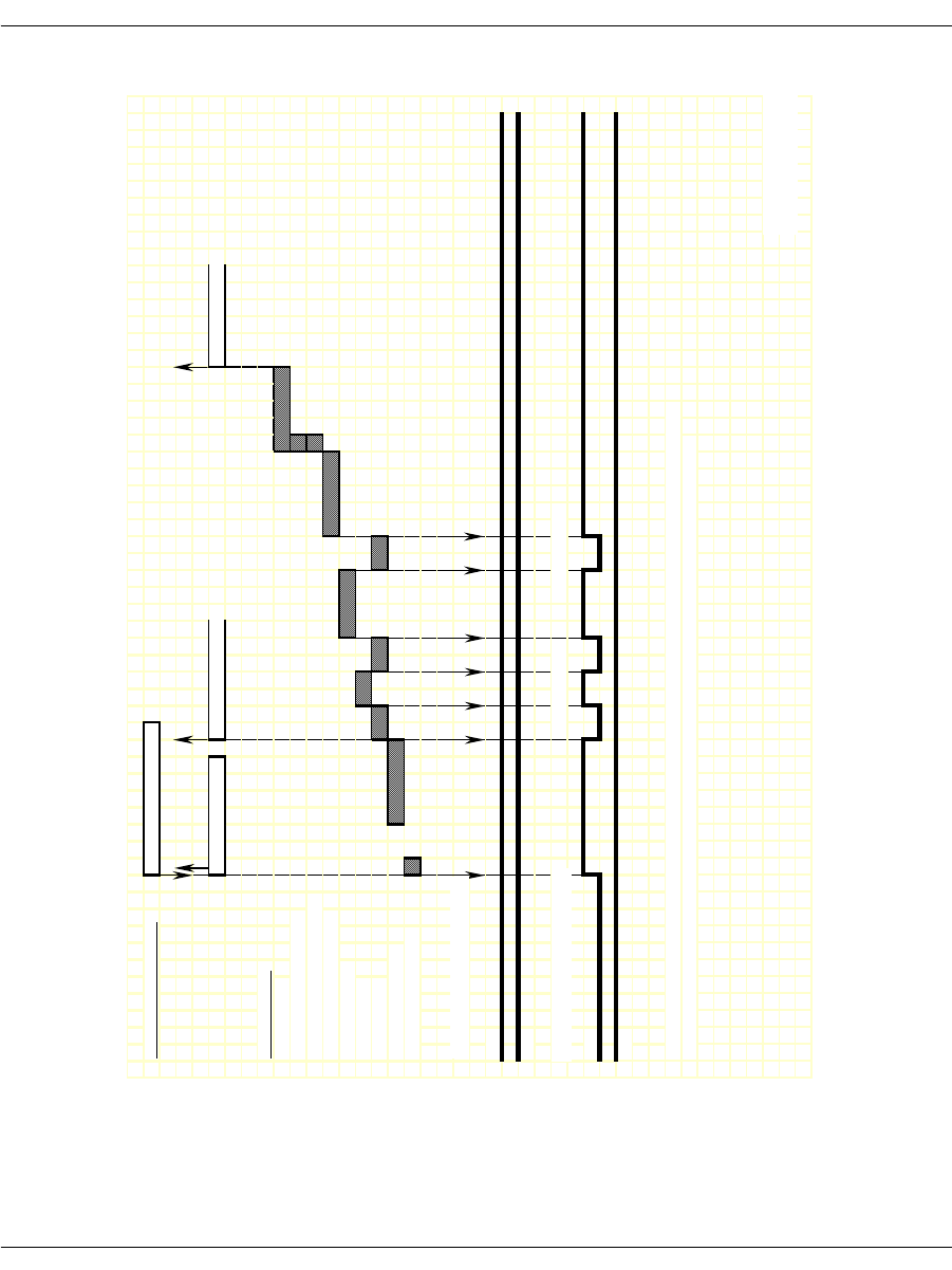
Loop Start Signaling
November 2009 312
Figure 44. FXS Loop Start – Outgoing Call Timing Diagram
IISDN SMI MESSAGES: L4L3mCALL_REQUEST
L3L4mPROGRESS L3L4mSEIZE_COMP L3L4mCONNECT
IISDN TIMERS:
answer_timer
hooktimer_offhook_answe
r
hooktimer_onhk_mod_out_rls
dptimer_end_dial_pause
dptimer_interdigit
dptimer_make
dptimer_break
fixed_pause_timer
glare_detection_timer
RECEIVE HOOKSWITCH, FXO:
A
Bi
t
B Bit
TRANSMIT HOOKSWITCH, FXS:
A
Bi
t
B Bit
NOTE: This diagram is designed to give the reader a general understanding of the sequence of events for this robbed
bit protocol over time. The timers and spacing on this graph are not proportional to the actual events that occur.
Revised 10-Nov-98
Revision 1.3
DP Digit "2" DP Digit "1"
RECEIVED BITS,
TRANSMITTED
Revised
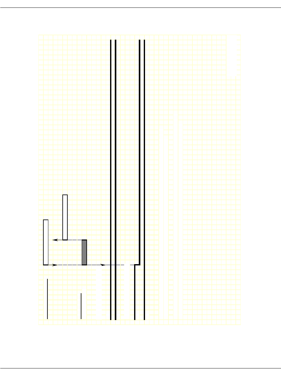
Loop Start Signaling
November 2009 313
Figure 45. FXS Loop Start – Outgoing Clear Timing Diagram
IISDN SMI MESSAGES: L4L3mCLEAR_REQUEST
L3L4mCLEAR_REQUEST
IISDN TIMERS:
guard_interval_timer
RECEIVE HOOKSWITCH, FXO:
A Bit
B Bit
TRANSMIT HOOKSWITCH, FXS:
A
Bi
t
B Bit
NOTE: This diagram is designed to give the reader a general understanding of the sequence of events for this robbed
bit protocol over time. The timers and spacing on this graph are not proportional to the actual events that occur.
NOTE: For FXS Loop Start Mode, there is no manner using the signalling bits in which to detect that the remote side has hung
up. The only way to do this is to detect a lack of data on the connection, and then initate call teardown from the local side.
Revised 10-Nov-98
Revision 1.3
RECEIVED BITS,
TRANSMITTED
Revised
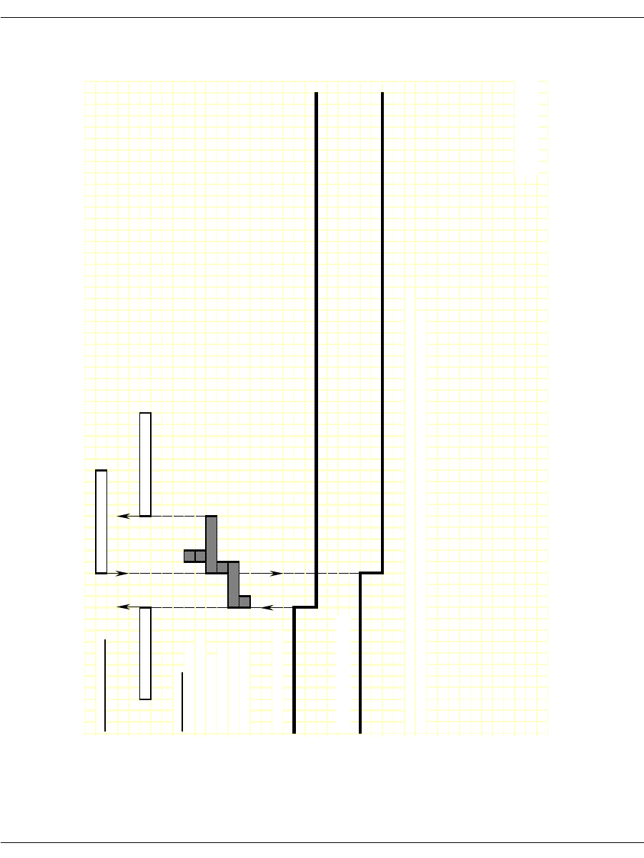
Loop Start Signaling
November 2009 314
Figure 46. Non-FXO/FXS RBS Protocols - Incoming Clear Timing
Diagram
IISDN SMI MESSAGES: L4L3mCLEAR_REQUEST
L3L4mDISCONNECT L3L4mCLEAR_REQUEST
IISDN TIMERS:
hooktimer_onhook_rls
hooktimer_offhook_inseize
guard_interval_timer
ign_insz_post_rls_timer
delayed_onhook_timer
hooktimer_onhook_rls
RECEIVE HOOKSWITCH:
TRANSMIT HOOKSWITCH:
NOTE: This diagram is designed to give the reader a general understanding of the sequence of events for this robbed
bit protocol over time. The timers and spacing on this graph are not proportional to the actual events that occur.
Revised 10-Nov-98
Revision 1.3
RECEIVED
TRANSMITTED
Revised
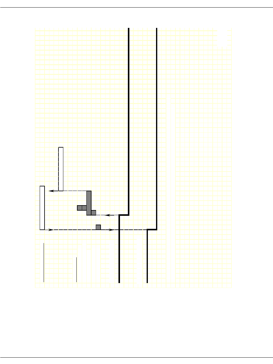
Loop Start Signaling
November 2009 315
Figure 47. Non-FXO/FXS RBS Protocols - Outgoing Clear Timing
Diagram
IISDN SMI MESSAGES: L4L3mCLEAR_REQUEST
L3L4mCLEAR_REQUEST
IISDN TIMERS:
hooktimer_onhook_rls
hooktimer_offhook_inseize
guard_interval_timer
ign_insz_post_rls_timer
hooktimer_onhook_rls
RECEIVE HOOKSWITCH:
TRANSMIT HOOKSWITCH:
NOTE: This diagram is designed to give the reader a general understanding of the sequence of events for this robbed
bit protocol over time. The timers and spacing on this graph are not proportional to the actual events that occur.
Revis
e
RECEIVED
TRANSMITTED
Revise
d

November 2009 316
8 - ISDN Call Processing and
Management
This chapter describes ISDN call processing using BSMI-level call
control.
The chapter has the following sections:
ISDN Call Processing Overview
Translating Q.931 to Simple Message Interface
Using the overlap_rcv feature of L4L3mENABLE_
PROTOCOL
Q.921/Q.931 Timers
Brooktrout modules provide multipurpose platforms for fully
integrated network access. The nature of the functions performed by
this interface are determined by the host application developed to
control this interface.
Note: This chapter applies only to BSMI (low-level call control)
users. Bfv call control users do not need to be concerned with
this information.
Note: QSIG is not supported by BSMI.
C language code fragments have been included to illustrate key
points in the text. It is recommended that the information in this
section be reviewed in conjunction with the BSMI section of the Bfv
API Reference Manual, Volume 5.

November 2009 317
BSMI interprets undecoded Q.931 packets from the network,
removing information not needed by most applications and making it
available via an L3L4m message. If you need specific Q.931
information not delivered with the message but that is documented
as contained in a Q.931 packet, such as call setup messages which
have two IEs (Information Elements) – Lower and Higher level
compatibilities, you can get access to the entire undecoded packet via
an L3L4mRAW_QDATA message (see the BSMI section of the Bfv
API Reference Manual, Volume 5, for details). Raw data for Q.931
packets that are not even processed by BSMI in the first place and
for Q.931 packets containing user-defined ISDN messages is also
notified via this message.

ISDN Call Processing Overview
November 2009 318
ISDN Call Processing Overview
This subsection presents an overview of ISDN incoming and
outgoing call setup and tear down and overlapped dialing. Switched
56 calls use a similar mechanism.
Making an ISDN Incoming Call
A typical incoming ISDN call is illustrated in Figure 48. In this call
scenario, the Brooktrout module is answering a call. The following
message exchange is relative to the module:
1. Call arrival is indicated by receipt of a SETUP message from the
network containing information about the call (calling party and
called party numbers, etc.).
2. The module generates two messages upon receipt of the SETUP.
CALL PROCEEDING message to the network indicating the
call is being processed.
L3L4mSETUP_IND message to the host indicating receipt of
the SETUP message from the network; information about
the call (calling party and called party numbers, etc.) is
included in this message if received from the network.
3. If the incoming call is to be accepted, the host optionally sends an
L4L3mALERTING_REQUEST message to the module.
4. Upon receipt of the L4L3mALERTING_REQUEST message, the
module sends an ALERTING message to the network.
5. The host then sends an L4L3mCONNECT_REQUEST to the
module, asking that the call be connected; the host can consider
the call connected at this point unless an error indication is
received.
6. Upon receipt of the L4L3mCONNECT_REQUEST message, the
module sends a CONNECT message to the network.
7. The network immediately responds with a CONNECT
ACKNOWLEDGE message and the call is connected.
This scenario does not use B-channel negotiation, which would
require additional message exchanges between the module and host.
B-channel negotiation is a feature that allows you to specify on
which B-channel you want an incoming call to be established.

ISDN Call Processing Overview
November 2009 319
Notification of incoming calls comes via a SETUP_IND message
which contains the B-channel number the network would like to set
the call up on. By turning on negotiation, you can specify a different
(specific) B-channel on which to establish rather than the one
requested by the network. In this case, a CALL PROCEEDING
message will not get sent to the network and it is your responsibility
to notify the network of the desired B-channel via any one of the
following three messages: L4L3mCALL_PROCEEDING_REQUEST,
L4L3mALERTING_REQUEST, and L4L3mCONNECT_REQUEST.
Note: If using more than one of these messages, you should be
consistent on the B-channel value.
You might want to do B-channel negotiation in situations where
each of the channels is hard-code mapped to different locations
depending on the type of call (data, voice, fax) received. If an
incoming call to a channel is not the type of call that is handled by
that (network-assigned) channel, then it must be (re)established on a
channel that can handle the type of that call, or else the call won’t be
handled properly.
This feature is turned on by setting:
l43.data.enable_protocol.level3.cnfg.q931.b_chan_negot=1
in the ENABLE_PROTOCOL message. In the case where the
network indicates that the B-channel it is offering is non-negotiable,
and the l43.data.enable_
protocol.level3.cnfg.q931.proc_on_exclusv field was set
when the protocol was enabled, the calling process will proceed with
a CALL PROCEEDING message being sent to the network without
requiring you to indicate one. The network indicates that the
B-channel it is offering is non-negotiable. The user had agreed to
proceed by having set the proc_on_exlusv field.
Connect Acknowledge is reported to the module but is not
automatically reported to the host via the Bfv API. In order to
retrieve L3L4mCONN_ACK_IND, set the field below to 1 in your
ENABLE_PROTOCOL message:
l43.data.enable_protocol.level3.cnfg.q931.subscribe_connack=1
The stack can consider the call connected after sending the
L4L3mCONNECT_REQUEST message or wait until it receives the
CONNECT ACKNOWLEDGE from the network. If you do not want
to wait for the network response, set the field below to 1 in your
ENABLE_PROTOCOL message:
l43.data.enable_protocol.level3.cnfg.q931.no_rx_conn_ack=1

ISDN Call Processing Overview
November 2009 320
It is also possible to configure BSMI to generate a SETUP_ACK
rather than a CALL_PROCEEDING message upon arrival of a setup
message.
Figure 48. ISDN Incoming Call
As in the case of a call, BSMI also handles the call model where a
SETUP_ACK generated instead of a call proceeding.
Network Module Host
CALL PROCEEDING
ALERTING
CONNECT
L3L4mSETUP_IND
SETUP
L4L3mALERTING_REQUEST
L4L3mCONNECT_REQUEST
CONNECT ACKNOWLEDGE

ISDN Call Processing Overview
November 2009 321
Making an ISDN Outgoing Call
A typical outgoing ISDN call is illustrated in Figure 49. In this call
scenario, the module is making an outgoing call. During an outgoing
call, if the phone number is more than 20 digits long, the application
automatically sends the number using overlapped dialing (See ISDN
Overlapped Dialing on page 323 for more information). The following
message exchange is relative to the module:
1. The host initiates an outgoing call by sending an L4L3mCALL_
REQUEST message to the module; this message must contain
information about the call (calling party and called party
numbers, and so on).
2. Upon receipt of the L4L3mCALL_REQUEST message, the
module issues a SETUP message to the network; this message
must contain information about the call (calling party and called
party numbers, and so on).
3. The network responds to the SETUP with a CALL
PROCEEDING message indicating the call request is being
processed.
4. Following the CALL PROCEEDING, the network sends an
ALERTING message indicating the called party is ringing.
5. Upon receipt of the ALERTING message, the module generates
an L3L4mALERTING message to the host.
6. The network then sends a CONNECT message to the module
indicating it is connecting the call.
7. The module generates two messages upon receipt of the
CONNECT.
L3L4mCONNECT message to the host; the host can consider
the call connected at this point
CONNECT ACKNOWLEDGE message to the network
indicating the CONNECT message has been acknowledged

ISDN Call Processing Overview
November 2009 322
Figure 49. ISDN Outgoing Call
Call Proceeding (L3L4mCALL_PROCEEDING) is reported to the
module but is not automatically reported to the host via the Bfv API.
In order to retrieve this message, set the field below to 1 in your
ENABLE_PROTOCOL message:
143.data.enable_protocol.level3.cnfg.q931.report_incoming_callproc=1
The default is that the stack sends a CONNECT ACKNOWLEDGE
upon receiving a CONNECT. If you do not want to automatically
respond in this manner, set the field below to 1 in the ENABLE_
PROTOCOL message:
l43.data.enable_protocol.level3.cnfg.q931.no_tx_conn_ack = 1
You can specify that, if a desired B-Channel to establish a call on is
unavailable, another available B-Channel, which is chosen by the
module, will automatically be used. To do this, set l43.data.call_
req_data.preferred = 1 to enable this feature in the CALL_
REQUEST message.
Network Module Host
CALL PROCEEDING
ALERTING
CONNECT
L4L3mCALL_REQUEST
SETUP
L3L4mALERTING
L3L4mCONNECT
CONNECT ACKNOWLEDGE

ISDN Call Processing Overview
November 2009 323
ISDN Overlapped Dialing
The Euro-ISDN protocol only allows 20 digits to be sent as a group
(en-block) when placing a call. For longer phone numbers, the
application must use overlapped dialing— the process of sending
extra digits after the initial call setup. This process allows:
The application to dial very large phone numbers
The remote end to start answering a call before it receives all the
digits
The Bfv API automatically performs overlapped dialing on Euro-
ISDN outgoing calls using E1 or BRI lines when the phone number
is longer than 20 digits. Users will be able to place a call with up to
255 digits in the dial string on Euro-ISDN without requiring changes
in the application.
Applications automatically send overlapped digits when the user
calls BfvCallSetup, BfvLineDialString or
BfvLineOriginateCall and provides a dial string of more than 20
digits when Euro-ISDN is being used.
The feature divides the dial string into banks of 20 digits and uses
the overlapped dialing feature in Euro-ISDN to send one block of
digits at a time.
ISDN Call Clearing - Initiated by Module
A typical module-initiated call clearing (tear down) sequence is
illustrated in Figure 50. The following message exchange is relative
to the module:
1. The host initiates the call clearing procedure by sending an
L4L3mCLEAR_REQUEST message to the module.
2. Upon receipt of the L4L3mCLEAR_REQUEST message, the
module sends a DISCONNECT message to the network.

ISDN Call Processing Overview
November 2009 324
3. The network responds to the DISCONNECT with a RELEASE
message.
4. The module generates two messages upon receipt of the
RELEASE:
RELEASE COMPLETE message to the network, indicating
the call has been cleared
L3L4mCLEAR_REQUEST message to the host, indicating
the call has been disconnected
Figure 50. ISDN Call Clearing - Initiated by Module
Network Module Host
RELEASE
L4L3mCLEAR_REQUEST
DISCONNECT
L3L4mCLEAR_REQUEST
RELEASE COMPLETE

ISDN Call Processing Overview
November 2009 325
If you want manual control over the sending of RELEASE
COMPLETE, set the field below to 1:
l43.data.enable_protocol.level3.cnfg.q931.release_complete_control = 1
An L4L3mCLEAR_REQUEST message will then send the
RELEASE COMPLETE message.
The host cannot consider a call disconnected and the channel
available for another call until the L3L4mCLEAR_REQUEST
message has been received from the module.
If the call is made using Switched 56 robbed bit signaling (not
ISDN), there is an additional waiting period between sending the
L4L3mCLEAR_REQUEST and receiving the L3L4mCLEAR_
REQUEST indicating the channel is available. This interval is equal
to the value of the guard_interval_timer and is usually 100 ms. Refer
to Chapter , Robbed Bit Signaling on page 264 for more information
on robbed bit signaling timers.
ISDN Call Clearing - Initiated by Network
A typical ISDN call clearing is illustrated in Figure 51. In this call
scenario, the module responds to the network’s request to disconnect
a call. The following message exchange is relative to the module:
1. The network initiates the call clearing procedure by sending a
DISCONNECT message to the module.
2. Upon receipt of the DISCONNECT, the module generates an
L3L4mDISCONNECT message to the host indicating the
network is clearing the call.
3. The host responds with an L4L3mCLEAR_REQUEST message
indicating the call should be cleared.
4. Upon receipt of the L4L3mCLEAR_REQUEST, the module
generates a RELEASE message to the network.
5. The network responds to the received RELEASE by generating a
RELEASE COMPLETE message.
6. Upon receipt of the RELEASE COMPLETE message, the module
informs the host the call has been cleared using the
L3L4mCLEAR_REQUEST message.
It should be noted that the host cannot consider a call disconnected
and the channel available for another call until the L3L4mCLEAR_
REQUEST message has been received from the module.

ISDN Call Processing Overview
November 2009 326
If the call is made using Switched 56 robbed bit signaling (not
ISDN), there is an additional waiting period between sending the
L4L3mCLEAR_REQUEST and receiving the L3L4mCLEAR_
REQUEST indicating the channel is available. This interval is equal
to the value of the guard_interval_timer and is usually 100 ms. Refer
to Chapter , Robbed Bit Signaling on page 264 for more information
on robbed bit signaling timers.
Figure 51. ISDN Call Clearing - Initiated by Network
Network Module Host
RELEASE
DISCONNECT
RELEASE COMPLETE
L3L4mDISCONNECT
L4L3mCLEAR_REQUEST
L3L4mCLEAR_REQUEST

Translating Q.931 to Simple Message Interface
November 2009 327
Translating Q.931 to Simple Message Interface
Table 14 translates Q.931 messages to the appropriate Simple
Message Interface (SMI) message and compares them to their
corresponding message.
Table 14. Q.931 Message Comparison Table
Q.931Message BSMI Message(L4L3m) BSMI Message (L3L4m)
ALERTing ALERTING_REQUEST ALERTING
CALL PROCeeding CALL_PROCEEDING_
REQUEST CALL_PROCEEDING
CONNect CONNECT_REQUEST CONNECT
CONNect ACKnowledge nothing CONN_ACK_IND
PROGress PROGRESS_REQUEST PROGRESS
SETUP CALL_REQUEST SETUP_IND
SETUP ACKnowledge SETUP_ACK_REQUEST SETUP_ACK
RESume RESUME_REQUEST RESUME_REQUEST
RESume REJect RESUME_REJECT RESUME_REJECT
SUSPend SUSPEND_REQUEST SUSPEND_REQUEST
SUSPend ACKnowledge SUSPEND_ACK SUSPEND_ACK
SUSPend REJect SUSPEND_REJECT SUSPEND_REJECT
USER INFOmation USER_INFO USER_INFO
DISConnect CLEAR_REQUEST DISCONNECT
RELease CLEAR_REQUEST CLEAR_REQUEST
RELease COMPlete nothing CLEAR_REQUEST
Note: If l43.data.enable_
protocol.level3.cnf
g.q931.release_
complete_control is
set, CLEAR_REQUEST
will send this message.
RESTart RESTART CLEAR_WITH_RESTART_
REQUEST or RESTART

Using the overlap_rcv feature of L4L3mENABLE_PROTOCOL
November 2009 328
Using the overlap_rcv feature of
L4L3mENABLE_PROTOCOL
What is Overlap Receive?
When an ISDN call is received from the Public Telephone Network,
the caller information arrives in a Q.931 SETUP message. Typically,
this SETUP message contains all the information necessary for the
user to properly route, switch and/or complete the call: information
about the type of call (voice, modem, data, and so on), caller ID
information, and so on.
Overlap Receive mode occurs when the incoming SETUP message
contains no CALLED party information, or incomplete CALLED
party information. The CALLED party information is necessary to
complete a circuit-switched call, because it identifies the complete
number that the originator is dialing.
The ITU Q.931 Recommendation defines a SENDING_COMPLETE
Information Element as an indicator of when a SETUP message has
complete CALLED party number information. If a SETUP message
is received and there is no SENDING_COMPLETE info element in
the message, the user is expected to enter Overlap Receive mode.
RESTart ACKnowledge nothing nothing
SEGMENT nothing nothing
CONGestion CONtrol nothing nothing
INFOmation INFO_REQUEST INFO
NOTIFY nothing UNIVERSAL
STATus nothing STATUS_IND
STATus ENQuiry nothing nothing
FACILITY UNIVERSAL UNIVERSAL
Table 14. Q.931 Message Comparison Table (Continued)
Q.931Message BSMI Message(L4L3m) BSMI Message (L3L4m)

Using the overlap_rcv feature of L4L3mENABLE_PROTOCOL
November 2009 329
BSMI Reference Notes
Support for Overlap Receive mode are enabled using the overlap_rcv
flag in the BSMI_Q931_CNFG structure of L4L3mENABLE_
PROTOCOL messages.
If the Host application expects to support Overlap Receive calling
models (more typical of E1 and EURO-based BRI installations than
domestic T1 installations), it should set the overlap_rcv flag to “1”
when enabling the Q.931 D-channel. Example:
L4_to_L3_struct l43msg;
memset (&l43msg, 0, sizeof(l43msg));
l43msg.lapdid = 0;
l43msg.msgtype = L4L3mENABLE_PROTOCOL;
l43msg.data.enable_protocol.level1.l1_mode = IISDNl1modHDLC;
l43msg.data.enable_protocol.level2.l2_mode = IISDNl2modLAP_D;
l43msg.data.enable_protocol.level2.dce_dte = IISDNdirUSER_SIDE;
l43msg.data.enable_protocol.level3.l3_mode = IISDNl3modQ931;
l43msg.data.enable_protocol.level3.cnfg.q931.switch_type =
IISDNstUNKNOWN;
l43msg.data.enable_protocol.level3.cnfg.q931.variant = IISDNvarCCITT;
l43msg.data.enable_protocol.level3.cnfg.q931.overlap_rcv = 1;
BSMIControlWrite (fd, l43msg);

Using the overlap_rcv feature of L4L3mENABLE_PROTOCOL
November 2009 330
How Overlap Receive Mode Changes
Call Control Events Presentation
Volume 5, Bfv API Reference Manual describes the normal call
control events associated with ISDN Call Processing and
Management. These events occur when incoming SETUP messages
contain all the appropriate CALLED_PARTY information elements
and SENDING_COMPLETE information elements.
When the overlap_rcv flag is enabled and the SETUP message arrives
with incomplete CALLED_PARTY information, the call control
events change as follows:
1. Network presents SETUP message to the module, with either
incomplete CALLED_PARTY information element present, or no
SENDING_COMPLETE info element present.
2. Instant ISDN activates the T302 timer, sends a SETUP_
ACKNOWLEDGE message to the Network, and enters the
Overlap Receive state. Instant ISDN also presents the initial call
information to the Host in an L3L4mSETUP_IND message.
Note: The T302 timer is under Host control (see IISDN_Q931_
TIMERS in the IISDN.H header file) with a default timer
value of 15 seconds.
3. The Network sends the remainder of the call information (if any)
in one or more INFORMATION messages. Each information
message arrives as an L3L4mINFO event to the Host application,
which contains CALLED_PARTY information elements, as well
as an indicator for SENDING_COMPLETE information
elements. Each time an INFORMATION message is received
without a SENDING_COMPLETE info element present in the
message, Instant ISDN restarts the T302 timer.
4. Presence of the SENDING_COMPLETE information element is
optional. Some ISDN switches and dialing plans will present all
of the CALLED_PARTY information and never send a
SENDING_COMPLETE info element in the final
INFORMATION or SETUP message.
5. When the final INFORMATION message has been received
(indicated by presence of the SENDING_COMPLETE
information element, or when the host has determined that the
CALLED_PARTY information is sufficient to complete the call),
the Host application issues an L4L3mCALL_PROCEEDING and
the call control events will then transpire normally.

Using the overlap_rcv feature of L4L3mENABLE_PROTOCOL
November 2009 331
Network Brooktrout Controller Host
Setup (no sending complete
or called party #IE) overlap_rcv ENABLED
SETUP ACKNOWLEDGE
INFORMATION
L3L4mSETUP_IND
L3L4mINFO
If no SENDING_COMPLETE IE is present, or when
Module cannot determine if CALLED_PARTY info
is complete, Module issues request for further info.
L3L4mINFO_REQUEST
INFORMATION REQUEST
INFORMATION L3L4mINFO
L3L4mINFO_REQUEST
INFORMATION
L3L4mINFO
If no SENDING_COMPLETE IE is present, or when
Module determines that CALLED_PARTY info is complete,
Module moves to CALL_PROCEEDING state.
L3L4mCALL_PROCEEDING_REQUEST
CALL_PROCEEDING

Q.921/Q.931 Timers
November 2009 332
Q.921/Q.931 Timers
An application can change the default behavior in Instant ISDN
Software Level 2 and Level 3 parameters by issuing ENABLE_
PROTOCOL.
L4L3mENABLE_PROTOCOL contains an IISDN_L2_CONST
structure that defines Level 2 parameters and an IISDN_Q931_
TIMERS structure that configure Level 3 timers. The IISDN_Q931_
TIMERS structure is only valid when the Level 3 mode (l3_mode)
value in the message is IISDNl3modQ931. Table 15 and Table 16 list
the parameters for both structures.
When altering these values, refer to the system specification for the
switching system to which you are connecting the Brooktrout
Controller for valid timer and window values. Level 2 timers are
specified in 1 millisecond “ticks;” Level 3 timers in 100 millisecond
“ticks.”
Note: Dialogic strongly recommends that you use the default values
for Level 2 and Level 3 parameters and internal buffers.
Failure to do so might result in a system irregularity. If you do
need to change the configurations and buffer sizes, call
Dialogic Technical Services and Support first and seek
consultation. Internal buffer sizes for different Brooktrout
Controller configurations are found in IISDN.h.
Table 15. Q.921 Timers (Level 2 Parameters)
Data Type Mnemonic Definition
IISDN_L2_
LAP_
CONSTS
12 Setting a field to 0 causes the default value to be
used. Some timers have two possible default values
depending on whether or not the line is a BRI (set
by the q931_cnfg.basic_rate flag.
unsigned
short t200 Maximum retransmission time. Default value is
1000 (1 second).
unsigned
short t201 Minimum retransmission TEI Identity check.
Default value is 1000 (1 second).
unsigned
short t202 Minimum TEI Identity request. Default value is
2000 (2 seconds).
unsigned
short t203 Maximum link inactivity. Default value is 30
seconds. For NET-5 signaling, this timer should be
set to 10 seconds. BRI default is 10000 (10
seconds).

Q.921/Q.931 Timers
November 2009 333
unsigned
short n200 Maximum number of retransmissions. Default
value is 3.
unsigned
short n201 Maximum number of octets in an I frame.
Currently the maximum is 240.
unsigned
short n202 Maximum number of transmissions of a TEI
request message. Default value is 3.
unsigned
short KMaximum transmit window. Default value is 7;
maximum value is 127. BRI default is 1.
Table 15. Q.921 Timers (Level 2 Parameters) (Continued)
Data Type Mnemonic Definition
Table 16. Q.931 Timers (Level 3 Parameters)
Data Type Mnemonic Definition
IISDN_Q931_
TIMERS q931 Structure that includes changes to the Q.931 timer
values, if any. A value of 0xFFFF disables the
timer. Setting a field to 0 causes the default to be
used. Some timers have two possible default
values depending on the connection type/variant
used. For example, if the variant field value is
IISDNvarCCITT in an L4L3mENABLE_
PROTOCOL message, or the conn_type field
contains an IISDNctCCITT value in an
L4L3mENABLE_D_CHANNEL message, the
CCITT default value below is used. For all other
connection type or variant values, the standard
default value is used.
unsigned
short t302 Q.931 Overlap Receiving timer. Default value is
150 (15 seconds).
unsigned
short t305 Q.931 Disconnect Request state timer. Default
value is 50 (5 seconds) and the ITU-T default value
is 300 (30 seconds).
unsigned
short t308 Q.931 Release Request state timer. Standard
default value is 50 (5 seconds) and the ITU-T
default value is 40 (40 seconds).
unsigned
short t313 Q.931 Connect Request state timer. Default value
is 50 (5 seconds) and the ITU-T default value is 40
(4 seconds).
unsigned
short t314 Q.931 Segment message time. Default value is 40
(4 seconds).
unsigned
short t316 Q.931 Restart Request state timer. Default value is
1200 (120 seconds).

Q.921/Q.931 Timers
November 2009 334
If layer 2 has been enabled, you will receive the data (termed
payload) you expect with the layer 2 headers stripped off and all the
data reliability checks already performed. If layer 2 has not been
enabled, you will receive intact layer 2 packets, which will contain
the payload. These packets will need to be processed, and a layer 2
stack will have to be implemented all the while extracting the
payload.
HDLC packetization does not need to be enabled, instead you can
choose the raw mode option. To do this, both HDLC headers will
need to be either stripped off or recognized, and the layer 2 packet
headers inside the HDLC headers to get to the payload.
unsigned
short t318 Q.931 Resume Request state timer. Default value
is 1200 (120 seconds).
unsigned
short t319 Q.931 Suspend Request state timer. Default value
is 1200 (120 seconds).
unsigned
short t3m1 Q.931 Maintenance SERVICE ACK timer. Default
value is 1200 (120 seconds). Default value must be
used for NFAS configurations.
unsigned
short t321 Q.931 NFAS D-channel backup timer. Default
value is 400 (40 seconds).
Table 16. Q.931 Timers (Level 3 Parameters) (Continued)
Data Type Mnemonic Definition

November 2009 336
9 - Using the BSMI R2 Signaling
Capability
This chapter describes R2 signaling as used with BSMI-level call
control.
The chapter has the following sections:
CPE Signaling Model
Enabling the R2 Protocol
Brooktrout boards offer E1 CAS signaling for customer premise
equipment (CPE).
The protocols supported are:
ITU's R2 (Line Signaling and Inter-register Signaling) and
national variants
LEC protocols (Wink Start, Delay Dial, Immediate Start, FXO
Loop Start, FXS Loop Start, FXO Ground Start, FXS Ground
Start)
Dialogic's implementation of the R2 protocol contains a number of
parameters that are used to configure the module to conform to the
ITU recommendations (refer to ITU Blue Book, Signaling System
R2, Volume VI Fascicle VI.4, Q.421 - Q.424, digital line signaling,
and Q.440 - Q.458, compelled inter-register signaling). The fully
embedded R2 protocol stack consists of digital line signaling (R2

CPE Signaling Model
November 2009 337
Line Signaling) and MF compelled (MFC) (R2 Inter-register
Signaling). Signaling is controlled via the BSMI interface in a
manner similar to Q.931 and LEC protocols.
Note: This chapter applies only to BSMI (low-level call control)
users. Bfv call control users cannot use this information.
The LEC protocols are described in Chapter , Robbed Bit Signaling
on page 264.
Please contact Dialogic Technical Services and Support for a list of
supported variants of the R2 protocol. See the Bfv API Reference
Manual, Volume 5 for details.
CPE Signaling Model
This section describes the general signaling model that is
implemented by the Brooktrout R2 stack. This model is valid for a
large number of national variants that are found worldwide.
Customization via the BSMI will not be possible for variants that are
not described by this model.
The line signaling part of the protocol is illustrated in Table 17. The
Brooktrout implementation assumes that trunks are configured for
“both-way” working, that is outbound and inbound calls are possible
on the same trunk. Outbound-only and inbound-only trunk
configuration is not currently supported. In the discussion to follow,
“forward” is synonymous with outbound and “backward” is
synonymous with inbound.

CPE Signaling Model
November 2009 338
Table 17. Line Signaling Model
State CAS Bits Notes
Outbound AB Inbound AB
Idle 10 10 Both outbound and inbound
channels are sending idle signal.
Seize 00 10 Outbound channel seizes the line.
Seize Acknowledge 00 11 Inbound channel initializes MFC
inter-register signaling and sends
the seize acknowledgment. When
the seize acknowledgment is
recognized by the outbound
channel, inter-register signaling
begins with the transmission of the
first DNIS digit.
If the call is accepted by the inbound side via the inter-register signaling, the answered state
is entered.
Answer 00 01
Answer 00 11 Metering pulses are possible. In
this example the pulse is
transmitted on the A bit. The
outbound side must not confuse
this with a clear back signal.
Answer 00 01 Metering pulse over, inbound
resumes transmission of the
answer signal.
If the call is rejected by the inbound side via the inter-register signaling, the outbound side is
responsible for clearing the call.
Clear forward 10 11 Outbound side sends clear forward.
Idle 10 10 Inbound side sends the idle signal.
Disconnection initiated by the inbound side.
Clear back 00 11 or 00 The hang-up might be signaled by a
clear back (AB=11) or by a forced
release (AB=00), as indicated by
network specifications.
Clear forward 10 11 or 00 Outbound side sends the clear
forward signal.

CPE Signaling Model
November 2009 339
The inter-register signaling performs the exchange of address
information via R2 MF tones. The split-band forward and backward
tone sets allow the definition of sets of forward and backward
protocol signals. The exchange is performed in a compelled manner
with the outbound channel sending a forward address signal that is
acknowledged by a backward signal that itself directs the
transmission of the next piece of address information. Information
passed from the outbound side to the inbound side is:
DNIS digits (Dialed Number Identification Service) representing
the called party
ANI digits (Automatic Number Identification) representing the
calling party
DNIS category (a.k.a. Call, Group II, or Toll category)
ANI category (a.k.a. Caller, User, or Group I category)
Circuit type (terrestrial or satellite)
Half echo-suppressor to be used or not used
Idle 10 10 Inbound side sends the idle signal.
Disconnection initiated by the outbound side.
Clear forward 10 01 Outbound side sends the clear
forward signal.
Release guard
(Optional; refer to
network
specifications)
10 11 This state is optional. The inbound
side responds to the clear forward
with a clear back signal and holds it
for a specified length of time.
Idle 10 10 Inbound side sends the idle signal.
Channel blocking is implemented according to ITU recommendations for “both-way” trunks.
The side performing the blocking is considered the inbound or backward channel.
Idle 10 10 Both ends of the channel are idle.
Blocked 10 11 Blocking signal is transmitted.
Idle 10 10 Blocking signal is removed and
both ends are in the idle state.
Table 17. Line Signaling Model (Continued)
State CAS Bits Notes
Outbound AB Inbound AB

CPE Signaling Model
November 2009 340
Information passed from the inbound side to the outbound side is:
Called line condition (for example, free with change, busy, etc.)
Network congestion
ITU recommendations specify a set of 6 frequencies to be used for
forward signals, and another 6 for backward signals. Each signal
consists of 2 frequencies, thus providing 15 forward signals and
15 backward signals. The recommendations allow countries to use
only 5 frequencies (10 signals) for forward signaling and 4
frequencies (6 signals) for backward signaling. Both the forward and
backward signals can assume a number of meanings depending on
the signaling state. Transition from one set of meanings (called a
'group') to another is controlled by transmission of specific signals.
ITU recommendations define 2 groups for forward signals (groups I
and II) and 2 for backward signals (groups A and B). Some countries
chose to define 3 groups in each direction (I, II and III for forward
signals and A, B and C for backward signals). The concept of 'groups'
allows more information to be conveyed (2 groups containing up to
15 signals results in 30 signals in each direction) without having to
increase the number of signal generators and detectors, which are
expensive resources.
The forward channel initiates inter-register signaling with the
transmission of the first DNIS digit. Subsequent forward
transmission is controlled by the last backward channel signal
response.
1. DNIS transmission processing
2. ANI transmission processing
3. Called line condition processing
The backward channel controls inter-register signaling in the sense
that after the first DNIS digit transmission, each subsequent forward
channel signal is a response to the last backward channel signal.
Following the first DNIS digit, the backward channel directs the
collection of the address information according to the inbound
application parameters associated with the call. The backward
protocol is abstracted into four processing states that correspond to
the four blocks of information that are sent by the forward side:
1. DNIS number collection
2. DNIS category
3. ANI number collection
4. ANI category

CPE Signaling Model
November 2009 341
Figure 52 illustrates an example inter-register exchange in which
the inbound protocol is configured to collect DNIS digits first,
followed by collection of ANI information, and concluding with the
exchange of DNIS category and called line condition. However,
variations on this exchange are possible, resulting from different
settings of the inbound protocol control parameters and the absence
of certain signals in a given variant. For instance, the inbound
protocol is configured to request ANI information following reception
of N DNIS digits. Following completion of ANI collection, the DNIS
collection is resumed. Another example is that a certain variant
might not define the forward signal that indicates the end of the
DNIS string. In this case, the inbound protocol must count the DNIS
digits and signal a request for other information when the required
number of DNIS digits has been collected.
Enabling the R2 Protocol on page 342 provides further detail on the
protocol control parameters, protocol signals, and protocol processing
actions provided by the Brooktrout R2 stack.
Figure 52. Inter-register Signaling
DNIS "digit" 1
Send next DNIS digit
DNIS "digit" 2
Send next DNIS digit
DNIS complete
Send ANI information
ANI catagory
Send next ANI
ANI digit "9"
Send next ANI
ANI digit "8"
Send next ANI
ANI complete
Send DNIS catagory
DNIS catagory
Called line condition (free, busy, etc.)
Backward
Channel (called
number is 12)
Forward
Channel
(calling from
number 98)

Enabling the R2 Protocol
November 2009 342
Enabling the R2 Protocol
Using the R2 protocol is similar to using the LEC protocols. Each
individual channel is enabled using an L4L3mENABLE_CAS
message. When the module receives this message, it will initialize all
timers and data structures associated with the specified channel, put
the line in idle state “onhook” and respond with an L3L4mCAS_
STATUS message.
The application must select the following signaling type:
l43msg.data.cas_data.signalling_type = IISDNsigtypeR2_
CAS;
This mode operates the inter-register protocol stack on the DSP
processors. The iisdn.h file also identifies CAS signaling type
IISDNsigtypeR2_MF. This is an IISDN provision for operating R2
signaling on certain controller modules that incorporate modem
chips that provide basic MF generation and detection services to
IISDN. This capability is not currently released.
For all types of CAS signaling, the lapdid value (zero-based) in the
common message header indicates the network interface (line) on
the module receiving the message. The call reference value (field
call_ref) is a 16-bit value that must have the lapdid value in the most
significant 8 bits and the B-channel in the least significant 8 bits (if
no B-channel needs to be specified, use 0 for the least significant
byte). Since not all BSMI messages involve a B-channel, there is no
field in the common message header to specify the B-channel. For
some messages the B-channel is specified in the message-specific
data structure, and for others the B-channel is inferred from the call
reference value. Line and B-channel numbering is 0-based, and the
B-channel numbering is line-specific (that is, the first B-channel on
the second line is numbered 0).
All of the necessary trunk customization parameters are contained
in the IISDN_E1_CAS_R2_DATA portion of the L4L3mENABLE_
CAS structure. It is important that all parameters be filled. Most of
the parameters are network specific and cannot be modified without
resulting in protocol failure. Others are modifiable according to the
requirements of the user's application. Dialogic supplies C header
files that specify the parameter settings for certain national
variants.

Enabling the R2 Protocol
November 2009 343
BSMI does not support varying any parameter settings from channel
to channel on a single trunk. Trunk level configuration is performed
upon receipt of the first L4L3mENABLE_CAS message on that
trunk. However, L4L3mENABLE_CAS must be sent for every
channel in order for the channel to initialize and go on-hook.
Therefore, the IISDN_E1_CAS_R2_DATA structure should be filled
out identically for each channel's L4L3mENABLE_CAS.
The IISDN_E1_CAS_R2_DATA structure itself contains two
structures. Table 18 identifies the IISDN_R2_DIGITAL_LINE_SIG_
PARAMS sub-structure that contains the parameters required for
configuring the E1 CAS line protocol. None of these parameters is
modifiable once correctly specified for a particular network.
Table 18. R2 Digital Line Signaling Parameters
Name Description Units Range
r2OutSeizeTimer Time outbound side waits
for seize
acknowledgement signal.
ms Refer to network
specification, however, this
is typically set to 100-200
ms for a terrestrial circuit,
or 1-2 seconds for a satellite
circuit, plus approximately
32 ms to account for internal
detection latency.
r2OutAnswerTimeOut Maximum time between
reception of MF call
acceptance signal and
inbound answer.
ms Refer to network
specification.
inboundReleaseGuardTime Certain networks require
the inbound side to hold a
“release guard” state
(clear-back) for a certain
amount of time following
detection of the outbound
clear-forward signal.
ms 0: disable release guard
>0: refer to network
specification
inboundLineQualTimerIdle Inbound line signaling
event qualification time
during the idle state.
ms 0: qualify bits immediately
>0: refer to network
specification

Enabling the R2 Protocol
November 2009 344
Table 19 identifies the IISDN_R2_INTERREGISTER_PARAMS
sub-structure containing the parameters required used to configure
the MFC inter-register signaling.
c_d_cas_bits Specification of the CAS C
bit and D bit settings. 0: CD=00
1: CD=01
2: CD=10
3: CD=11
ClearbackControl Used by the outbound side
to determine whether the
network will use a release
guard (AB=11) or a forced
release (AB=00) signal to
tear down a call, The
selected signal is handled
accordingly, while the
other is simply ignored.
0: release guard
1: forced release
Table 18. R2 Digital Line Signaling Parameters (Continued)
Name Description Units Range
Table 19. R2 MFC Inter-register Signaling Parameters
Name Description Units Range
The Following Parameters Can Be Modified According to Application Requirements:
dnisMaxNumDigits Maximum number of DNIS digits
required. [0-IISDN_MAX_
DIGITS]
aniMaxNumDigits Maximum number of ANI digits
required. [0-IISDN_MAX_
DIGITS]
dnisNumDigitsBeforeANI The number of DNIS digits to
collect before requesting ANI. [1...N], where N =
dnisMinNumDigits
interForwardToneTimeOut Period associated with the inbound
channel “T3” timer that supervises
the interval elapsing between
recognition of two consecutive
forward tones. (Ref. ITU Q.476).
Seconds Typically, set to [8-24],
but refer to network
specification.
prePulseToneDelay The interval from the end of the
last backward signal and the start
of a backward pulse signal
(Ref. ITU Q.442).
ms Set to >= 100

Enabling the R2 Protocol
November 2009 345
pulseToneDuration Duration of a backward pulse
signal (Ref. ITU Q.442). ms Typically [100 - 200]
Outbound MFC Timers
forwardToneMaxOnTime Time associated with the outbound
“T1” timer that supervises the
interval between start of a forward
tone and cessation of the forward
tone (Ref. ITU Q.476).
Seconds This is typically in the
range [12-18], but refer
to network
specification.
forwardToneMaxOffTime Time associated with the outbound
“T2” timer that supervises the
interval when no forward tones are
sent. This interval consists of the
period waiting for the backward
tone to stop, as well as any
additional time needed for the next
forward tone to be known.
Seconds Typically set to > 24
(Q.476), but refer to
network specification.
forwardGroup2MaxOnTime Not used. Seconds Not used.
Protocol Control
dnisTimeOutAction Not used. Not used.
Protocol State Transition Specification
Each of the following is an array of length 16. Element zero is invalid and elements 1-15 correspond to
R2 MF signals 1-15. These allow the Call Setup Service Pack software to construct the proper state
transition tables for a given trunk.
Forward Channel Signal Definitions
endOfDNIS Signal end of DNIS pulsing; NOT
defined in some variants. Table 20
endOfANI_Available Signal end of ANI identification
when ANI digits are available. Table 20
InfoNotAvailable Indicates that ANI information is
restricted. There is usually no need
to distinguish from signal
“aniRequestNotAccepted”.
Table 20
aniCategoryDefault Default Group 1 category. Used if
category is not specified in a given
call request.
Table 20
Table 19. R2 MFC Inter-register Signaling Parameters (Continued)
Name Description Units Range

Enabling the R2 Protocol
November 2009 346
Backward Channel Signal Definitions
sendNextDigitDNIS Signal request for next DNIS digit
(state DNIS). Table 20
sendLastButOneDigitDNIS Signal request for last-but-one
DNIS digit (state DNIS). This
signal is not currently used.
Table 20
sendCallCategoryAndSwitch
ToGroupB_DNIS Requests transmission of the Call
Category and switch of the forward
channel to reception of the Group B
line condition (state DNIS).
Table 20
congestion Signals congestion (state DNIS). Table 20
sendCallingPartyCategory Requests transmission of the
calling party information starting
with the Calling Category (state
DNIS).
Table 20
callComplete_
SetUpSpeechPath Signals call acceptance, with
charge, without the need for the
Group II/Group B exchanges (state
DNIS).
Table 20
sendLastButTwoDigitDNIS Refer to ITU A-7. This signal is not
currently used. Table 20
sendLastButThreeDigitDNIS Refer to ITU A-8. This signal is not
currently used. Table 20
sendFirstDigitDNIS This signal is not currently used. Table 20
sendNextDigitANI Request transmission of the next
ANI digit (state ANI). Table 20
changeFrom_ANI_To_DNIS_
SendNextDigit Signal return to DNIS digit
collection, requesting the next
DNIS digit (state ANI).
Table 20
changeFrom_ANI_To_DNIS_
SendLastDigit Signal return to DNIS digit
collection, requesting the last
DNIS digit. This signal is not
currently used. (State ANI).
Table 20
Table 19. R2 MFC Inter-register Signaling Parameters (Continued)
Name Description Units Range

Enabling the R2 Protocol
November 2009 347
The MFC inter-register protocol is specified through a subset of the
parameters in Table 17 on page 338 that define the following:
1. Signal meaning definitions (events).
2. Actions associated with a given signal event. These specifications
are used to create a set of state transition tables for the desired
variant.
3. Protocol control parameters.
The parameter set might require extensions as support is added for
variants unidentified at this time. In addition, for a given variant,
certain signals and actions might not be defined. This restricts the
way in which the protocol can move through the processing states.
groupB_LineConditions Structure of Group B called line
conditions indexed by enumeration
IISDN_R2MFCP_GROUP_B_
CALLED_LINE_CONDITIONS.
Only a subset of these signals are
used in a given protocol variant.
Set those that are not used to the
“invalid” tone code.
Refer to Table 22
Call Progress Signal Generation
cpSignals Array of IISDN_CPGEN_MF_
PARAMS structures that define
the characteristics of the RING and
BUSY call progress signals. RING
must be defined as cpSignals[0]
and BUSY must be defined as
cpSignals[1].
Refer to Table 24
Table 19. R2 MFC Inter-register Signaling Parameters (Continued)
Name Description Units Range

Enabling the R2 Protocol
November 2009 348
Protocol Parameter Mechanics
The set of protocol parameters is specified according to a simple
procedure. Individual signal meanings are set to the appropriate MF
tone code. R2 MF tone codes for both forward and backward
channels are defined according to the enumeration in Table 20. If a
signal is not defined for a particular variant, its value is set to zero.
Table 20. IISDN_R2MF_SIGNAL_CODES Enumeration
Name Forward (Backward) Channel Value
IISDN_R2F_INVALID / IISDN_R2B_INVALID 0
IISDN_R2F_01 / IISDN_R2B_01 1
IISDN_R2F_02 / IISDN_ R2B_02 2
IISDN_R2F_03 / IISDN_R2B_03 3
IISDN_R2F_04 / IISDN_R2B_04 4
IISDN_R2F_05 / IISDN_R2B_05 5
IISDN_R2F_06 / IISDN_R2B_06 6
IISDN_R2F_07 / IISDN_R2B_07 7
IISDN_R2F_08 / IISDN_R2B_08 8
IISDN_R2F_09 / IISDN_R2B_09 9
IISDN_R2F_10 / IISDN_R2B_10 10
IISDN_R2F_11 / IISDN_R2B_11 11
IISDN_R2F_12 / IISDN_R2B_12 12
IISDN_R2F_13 / IISDN_R2B_13 13
IISDN_R2F_14 / IISDN_R2B_14 14
IISDN_R2F_15 / IISDN_R2B_15 15

Enabling the R2 Protocol
November 2009 349
Forward Channel
The set of forward channel actions to backward channel signals is
defined in Table 21.
Actions #2 - #8 might be used when processing DNIS or ANI digits
according to a particular protocol variant. The processing changes
state according to the current state and the particular event. For
instance, when in the ANI state, if a backward signal event requires
processing action PROCESS_NEXT_DNIS_DIGIT_REQUEST, then
that action occurs with a return to the DNIS state. In certain
protocol variants, a particular action might not be possible in a
particular state. For instance, a particular China PRC variant uses
R2B_01 to signal both the request for the next ANI digit and the
request for the next DNIS digit. Since there is no other, DNIS
related signal defined, the protocol cannot return to DNIS collection
until all ANI digits have been delivered.
Table 21. IISDN_R2MFC_FORWARD_ACTIONS
Name Description State
PROCESS_INVALID_BACKWARD_SIGNAL Process a backward
signal not defined; results
in protocol termination.
Any
PROCESS_NEXT_DNIS_DIGIT_REQUEST Process request for next
DNIS digit; if invoked
from the ANI state, then
a state change to DNIS
occurs.
DNIS or
ANI
PROCESS_LAST_BUT_1_DNIS_DIGIT_REQUEST Process request for N-1
DNIS digit. DNIS or
ANI
PROCESS_LAST_BUT_2_DNIS_DIGIT_REQUEST Process request for N-2
DNIS digit. DNIS or
ANI
PROCESS_LAST_BUT_3_DNIS_DIGIT_REQUEST Process request for N-3
DNIS digit DNIS or
ANI
PROCESS_RESTART_DNIS_REQUEST Process request for DNIS
restart. DNIS or
ANI
PROCESS_CALL_COMPLETE_CHANGE_TO_
GROUP_B Send Group II call
category and change to
Group B reception.
DNIS or
ANI

Enabling the R2 Protocol
November 2009 350
Backward Channel
Table 19 identifies the set of backward inter-register signals. The
tones defined are those used to support DNIS and ANI services
appropriate for customer premise equipment. Not all tones that are
possible under the ITU recommendations are required nor
implemented at this time. Certain tones might not be defined in a
particular variant. In such a case, the values of those tones should be
set to R2B_INVALID. In addition, certain signals are normally
expected to have the same absolute signal code whether the forward
channel is in state DNIS or state ANI. For example, this is true for
the congestion signal. However, distinct definitions are provided in
these cases to allow customization for an arbitrary variant.
PROCESS_CONGESTION_SIGNAL Process congestion signal. DNIS or
ANI
PROCESS_NEXT_ANI_DIGIT_REQUEST Process request for next
ANI digit. ANI
PROCESS_CALLING_PARTY_CATEGORY_
REQUEST Process request for
calling party (ANI)
information.
DNIS
PROCESS_CALL_ACCEPTED_NO_GROUP_B Process call accepted
without need for Group B
line condition.
DNIS
PROCESS_NATURE_OF_CIRCUIT_QUERY Process request for circuit
nature. DNIS
PROCESS_ECHO_SUPPRESSOR_QUERY Process request for use of
echo suppressor. DNIS
PROCESS_GROUP_B_LINE_CONDITION Process received
(Group B) called line
condition.
Line
condition
Table 21. IISDN_R2MFC_FORWARD_ACTIONS (Continued)
Name Description State

Enabling the R2 Protocol
November 2009 351
Table 22 identifies the enumeration of Group B called line
conditions. This enumeration forms the set of indices to array
groupB_LineConditions (Table 19). This allows the mapping of the
invariant enumeration values to and from the corresponding
backward signal codes that vary from trunk to trunk. A number of
user defined spares are provided.
Table 22. IISDN_R2MFCP_GROUP_B_CALLED_LINE_
CONDITIONS Enumeration
Name Description Value
IISDN_R2MFCP_LINE_FREE_CHARGE Line is free, charged. 0
IISDN_R2MFCP_LINE_FREE_NO_CHARGE Line is free, no charge. 1
IISDN_R2MFCP_LINE_ALTERNATE_ANSWER Line is free, alternate answer. 2
IISDN_R2MFCP_LINE_BUSY Line busy. 3
IISDN_R2MFCP_LINE_OUT_OF_ORDER Line is out of order. 4
IISDN_R2MFCP_LINE_UNALLOCATED Line is unallocated. 5
IISDN_R2MFCP_LINE_CONGESTION Circuit congestion. 6
IISDN_R2MFCP_LINE_SPARE_CONDITION_1 Spare 7
IISDN_R2MFCP_LINE_SPARE_CONDITION_2 Spare 8
IISDN_R2MFCP_LINE_SPARE_CONDITION_3 Spare 9
IISDN_R2MFCP_LINE_SPARE_CONDITION_4 Spare 10
IISDN_R2MFCP_LINE_SPARE_CONDITION_5 Spare 11
IISDN_R2MFCP_LINE_SPARE_CONDITION_6 Spare 12
IISDN_R2MFCP_LINE_SPARE_CONDITION_7 Spare 13
IISDN_R2MFCP_LINE_SPARE_CONDITION_8 Spare 14
IISDN_R2MFCP_LINE_SPARE_CONDITION_9 Spare 15

Enabling the R2 Protocol
November 2009 352
Table 23 identifies the set of backward channel actions to forward
signals.
Table 23. IISDN_R2MFCP_BACKWARD_ACTIONS
Name Description Valid
State
PROCESS_INVALID_FORWARD_SIGNAL This action is performed
when the protocol cannot
recover and the register must
immediately release. This
action is used in any protocol
state.
Any
PROCESS_DNIS_DIGIT Process received DNIS digit. DNIS
PROCESS_DNIS_END_OF_PULSING Process end-of-pulsing
(DNIS) signal. DNIS
PROCESS_CALL_CATEGORY_AND_SEND_
LINE_STATE Saves the call category and
requests the line state. DNIS
Category
PROCESS_CALL_CATEGORY_AND_
REJECT_CALL Processes an invalid call
category, rejecting the call. DNIS
Category
PROCESS_CALLING_CATEGORY_AND_
DONT_REQUEST_ANI Processes a calling category
for which there is no request
for ANI digits.
ANI
Category
PROCESS_CALLING_CATEGORY_AND_
REQUEST_ANI Processes calling category
and requests ANI digits. ANI
Category
PROCESS_CALLING_CATEGORY_AND_
REJECT_CALL Processes a calling category
that results in the rejection of
the call.
ANI
Category
PROCESS_CALLING_CATEGORY_
REQUEST_DENIED Process denied request for
the calling category. ANI
Category
PROCESS_ANI_DIGIT Process received ANI digit. ANI
PROCESS_ANI_END_OF_ID Process end of ANI signal
when digits are available. ANI
PROCESS_ANI_NOT_AVAILABLE Process signal indicating that
ANI digits are not available. ANI
PROCESS_ANI_RESTRICTED Process signal indicating that
ANI is restricted. ANI

Enabling the R2 Protocol
November 2009 353
Inbound calls require generation of call progress tones. If a call has
been accepted, BSMI will generate a finite number of RING tone
cycles before entering the answered state. If a call has been rejected,
BSMI will generate the BUSY signal until the call is cleared by the
outbound side. Table 24 identifies the IISDN_CPGEN_MF_
PARAMS structure that contains the parameters required to define
a call progress signal for generation by a DSP resource.
Table 24. IISDN_CPGEN_MF_PARAMS
Name Description Units Range
freqTone1 Frequency of tone #1 Hz [0-4000]
powerTone1 Power of tone #1 0.5 dB, relative to
power0dBm
Output
freqTone2 Frequency of tone #2 Hz [0-4000]
powerTone2 Power of tone #2 0.5 dB, relative to
power0dBm
Output
numCadences Number of distinct
cadences to generate
(on/off pairs)
[1,2,3]
makeTime1 Duration of first ON
cadence ms [1 - 8191]: tone plays
for this duration
0: no generation
>0: tone played
continuously
breakTime1 Duration of first OFF
cadence ms [1 - 8191]: tone is off
for this duration
0: silence not
generated between ON
cadences
< 0: silence is played
continuously
makeTime2 See makeTime1; not used
if numCadences = 1
breakTime2 See breakTime1; not used
if numCadences = 1

Enabling the R2 Protocol
November 2009 354
makeTime3 See makeTime1; not used
if numCadences = 2
breakTime3 See breakTime1; not used
if numCadences = 2
numCycles Number of cadence cycles
to generate. 0: pattern repeats
indefinitely
>0: finite number of
cycles
Table 24. IISDN_CPGEN_MF_PARAMS (Continued)
Name Description Units Range

Enabling the R2 Protocol
November 2009 355
R2 Call Control
This section presents an overview of R2 outbound and inbound call
setup and tear down. LEC protocols and ISDN use a similar
mechanism.
Once the trunk is configured, a particular channel that is enabled is
ready to dial an outbound call or process an inbound call from the
network. The R2 protocol stack automatically selects a DSP channel
(Boston channel) to perform the tone detection/generation
operations. The first B-channel on the first line uses the first DSP
channel, then each subsequent B-channel selects the next DSP
channel.
The first B-channel on the next line selects the DSP channel
immediately following the DSP channel selected for the last
B-channel of the previous line, thus ensuring there are no gaps in
the DSP channel usage caused by different number of timeslots in T1
and E1 lines.
During call setup - either inbound or outbound - the application
must not issue any commands to the Tone Generation and Tone
Detection facilities, as these would interfere with the R2 signaling
and cause the call to be abnormally terminated. If the application
connecting DSP channels and B-channels through the Telephony
Bus (H.100), it must ensure the appropriate DSP channel is free and
connected to the corresponding B-channel when it is ready to
receive/place calls. Once the call is connected, the DSP and
B-channels are remapped.

Enabling the R2 Protocol
November 2009 356
Outbound Call Setup
An outbound call request sequence that results in call acceptance by
the remote side is illustrated in Figure 53. The Host application
issues the module an L4L3mCALL_REQUEST message with the
following R2 payload entries:
l43msg.msgtype = L4L3mCALL_REQUEST;
l43msg.lapdid = 0x1;
l43msg.data.call_req_data.bchannel = 1;
l43msg.data.call_req_data.called_party.num_digits
l43msg.data.call_req_data.called_party.dnis_category
(set to an IISDN_R2MF_SIGNAL_CODES value)
l43msg.data.call_req_data.called_party.digits (ASCII
string)
l43msg.data.call_req_data.calling_party.num_digits
l43msg.data.call_req_data.calling_party.ani_category
(set to an IISDN_R2MF_SIGNAL_CODES value)
l43msg.data.call_req_data.calling_party.presentation_ind
(set to an IISDN_R2_ANI_XXXX value)
l43msg.data.call_req_data.calling_party.digits (ASCII
string)
l43msg.data.call_req_data.call_type (set to
IISDNcalltypR2_GND for a terrestrial circuit or
IISDNcalltypR2_SAT for a satellite circuit)

Enabling the R2 Protocol
November 2009 357
Call acceptance by the remote end is determined by BSMI during
MFC inter-register signaling. At this point, BSMI issues an
L3L4mALERTING message to the Host containing the IISDN_R2_
CALL_STATUS structure. The structure element
l34msg.data.al_con_data.r2_call_status.call_status,
provides indication (IISDN_R2_CALL_STATUS_CODES) of
whether the inbound side provided a Group B line condition
(IISDNR2statGROUP_B_AVAILABLE), or whether the call was
accepted without such indication (IISDNR2statGROUP_A_CALL_
ACCEPTED). In the case of the former, element
l34msg.data.al_con_data.r2_call_status.group_B
indicates the Group B call acceptance code.
When the inbound side answers the call, BSMI issues an
L3L4mCONNECT message to the Host.
Figure 53. Outbound Call Accepted
(1) L4L3mCALL_REQUEST
Host
(3) L3L4mCONNECT
(2) L3L4mALERTING
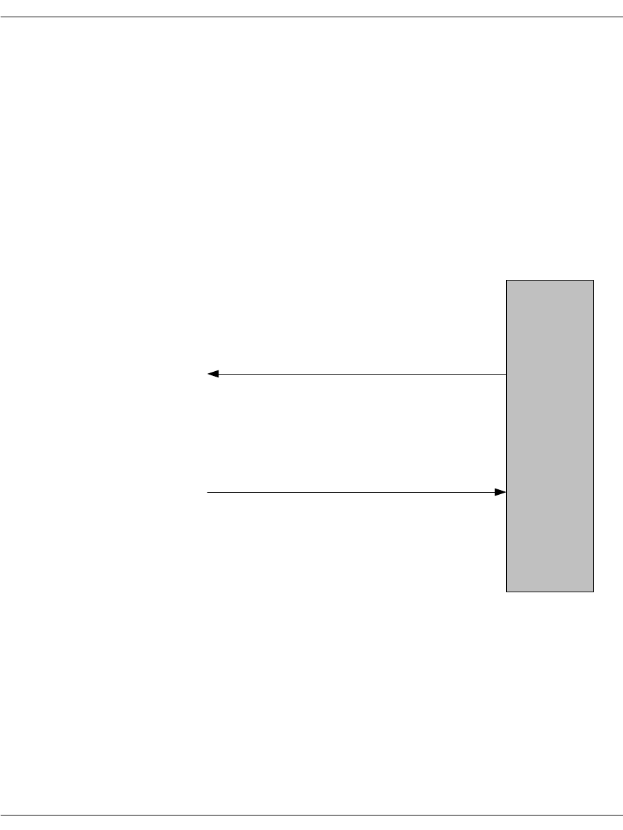
Enabling the R2 Protocol
November 2009 358
An outbound call request sequence that results in call rejection by
the remote side is illustrated in Figure 54. In this case, BSMI
determines that the call has been rejected during inter-register
signaling and automatically clears the call request. BSMI then
provides the Host indication of the failed call attempt with the
L3L4mCLEAR_REQUEST message. As in the case of call
acceptance, this message contains the IISDN_R2_CALL_STATUS
structure that is examined to determine the precise reason for call
failure. Normally, the call has been rejected by the remote side and a
status code of IISDNR2statGROUP_B_AVAILABLE is indicated
with the associated Group B reason for the rejection. However, other
failures are possible during abnormal operation and are indicated by
other values in enumeration IISDN_R2_CALL_STATUS_CODES.
Figure 54. Outbound Call Rejected
(1) L4L3mCALL_REQUEST
Host
(2) L3L4mCLEAR_REQUEST

Enabling the R2 Protocol
November 2009 359
Inbound Call Setup
Inbound call setup is illustrated in Figure 55. The host optionally
receives an L3L4mPRE_SEIZE message when BSMI detects an
incoming seizure. When all DNIS and ANI address information has
been collected, BSMI issues an L3L4mSETUP_IND message. After
examination of the address information, the host application might
wish to accept or reject the call.
In the case of call acceptance, the host provides an appropriate
Group B line condition in the L4L3m_CONNECT_REQUEST
message,
l43msg.data.al_con_data.r2_call_status.group_B = IISDN_R2MFCP_LINE_FREE_NO_
CHARGE;
Also, the number of ring cycles might be varied from the default
setting in Table 19 by setting the following parameter to a non-zero
value,
l43msg.data.al_con_data.r2_call_status.numberRings = 2;
The trunk can also be configured to accept all calls via the
inter-register parameter “addressCompleteMode.” In this case, the
L4L3m_CONNECT_REQUEST message is still sent, although the
Group B code is not required. Following completion of R2 MF
register signaling, BSMI will automatically play the RING signal for
a finite number of cycles. When the ring signal completes, BSMI
enters the answered state and issues an L3L4mCONN_ACK_IND
message to the host.
In the case of call rejection, the host provides an appropriate Group
B line condition in an L4L3mCLEAR_REQUEST message,
l43msg.data.clr_data.r2_call_status.group_B = IISDN_R2MFCP_LINE_BUSY;
Following completion of R2 MF register signaling, BSMI will
automatically play the BUSY signal for an indefinite number of
cycles. When the call has been cleared by the outbound side, BSMI
will issue an L3L4mCLEAR_REQUEST message to the Host after
both sides have assumed the idle state.
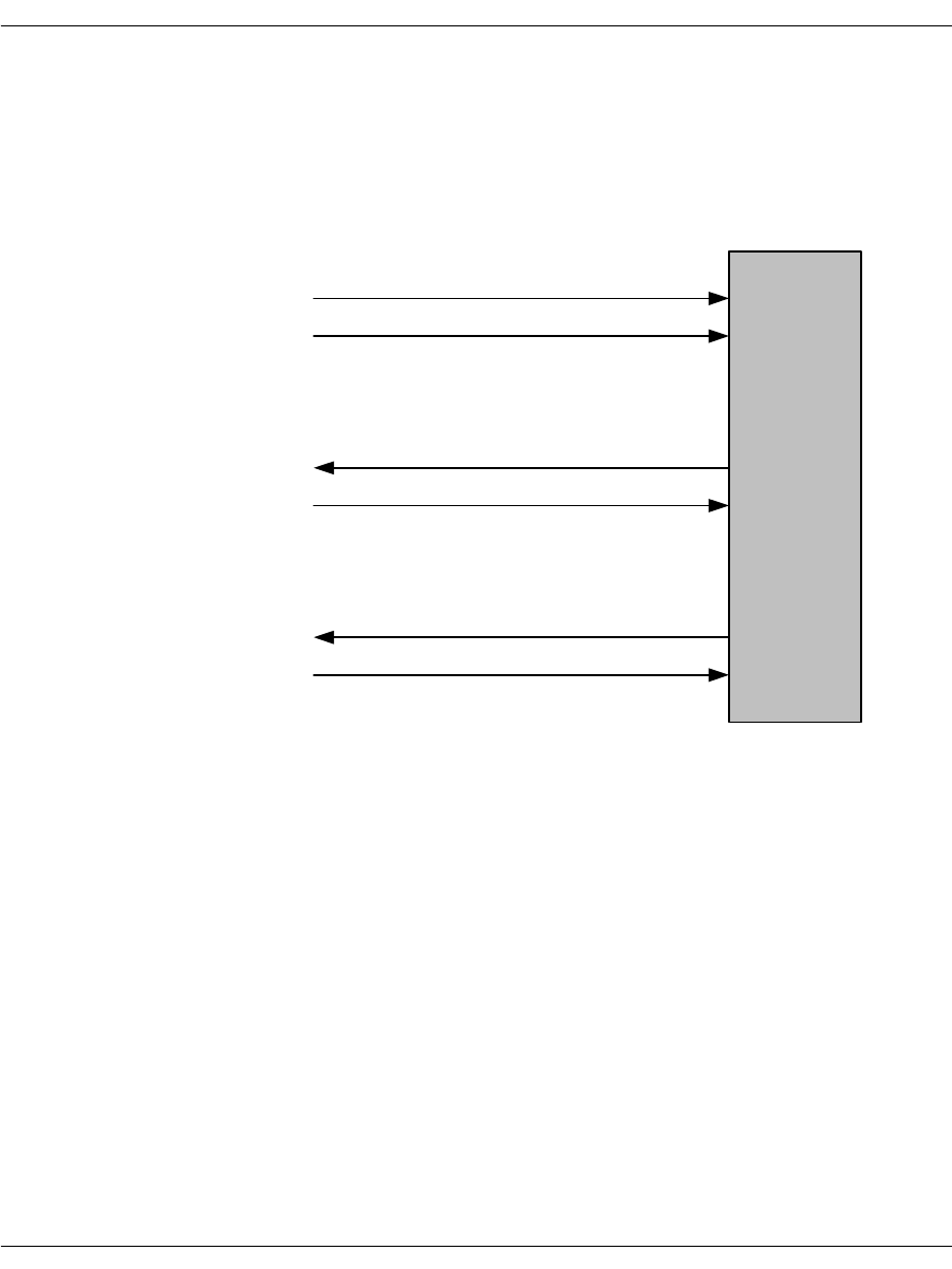
Enabling the R2 Protocol
November 2009 360
In the event that a failure occurs after the optional L3L4mPRE_
SEIZE message, but before the L3L4mSETUP_IND message, BSMI
will issue an L3L4mSTATUS_IND message containing the IISDN_
R2_CALL_STATUS structure that identifies the reason for the call
failure. No host action is required in this case, but the status
indication is logged for informational purposes.
Figure 55. Inbound Call Setup
(1) L3L4mPRE_SEIZE
Host
(2) L3L4mSETUP_IND
If call is accepted ...
(3) L4L3mCONNECT_REQUEST
(4) L3L4mCONN_ACK_IND
Else, if call is rejected ...
(3) L4L3mCLEAR_REQUEST
(4) L3L4mCLEAR_REQUEST
Enabling the R2 Protocol
November 2009 361
Call Tear Down
Figure 56 illustrates a call disconnection initiated by the network.
BSMI issues an L3L4mDISCONNECT message. The host responds
with a clear request that is followed with an L3L4mCLEAR_
REQUEST message when the channel has returned to the idle state.
Figure 56. Call Cleared by the Network
(1) L3L4mDISCONNECT
Host
(3) L3L4mCLEAR_REQUEST
(2) L4L3mCLEAR_REQUEST
Enabling the R2 Protocol
November 2009 362
Figure 57 illustrates a call disconnection initiated by the host
application. The host issues an L4L3mCLEAR_REQUEST message.
BSMI responds with an L3L4mCLEAR_REQUEST message when
the channel has returned to the idle state.
Figure 57. Call Cleared by the Module
(1) L4L3mCLEAR_REQUEST
Host
(2) L3L4mCLEAR_REQUEST
Enabling the R2 Protocol
November 2009 363
Channel Blocking
BSMI provides a mechanism for the Host application to block and
unblock individual channels as well as to receive indication that the
far end has blocked or unblocked a particular channel. Although the
R2 protocol remains “enabled”, a blocked channel is not available for
outbound or inbound calls. The BSMI message sequences for local
blocking and blocking by the network are illustrated in Figure 58.
Figure 58. Channel Blocking
(1) L4L3mCAS_CHAN_BLOCK
Host
(2) L3L4mCAS_CHAN_BLOCKED
Unblock a channel,
(3) L4L3mCAS_CHAN_BLOCK
(4) L3L4mCAS_CHAN_BLOCKED
Network blocks, unblocks a channel,
(3) L4L3mCAS_CHAN_BLOCK
(4) L3L4mCAS_CHAN_BLOCKED
Block a channel,

November 2009 364
10 - Packaging Your Application for
Windows®
This chapter describes how to package Dialogic® Brooktrout®
software so that you can deliver it to your customers as part of your
product.
The chapter has the following sections:
Package Options
Installation
About Plug and Play Components
Modifying Configuration Files
Including the Brooktrout Configuration Tool
Downloading Firmware Files
Removing Software
Removing the Plug and Play Driver
Your Brooktrout SDK includes an installation package (boston.msi)
to help you easily package your application for deployment on a
Windows® based platform. This package is referred to as the
Dialogic® Brooktrout® SDK.
This installation package provides you with the option to distribute
Brooktrout runtime software with your application, spawn it from
your own installation program, or select specific software modules
within the package and create your own installation program.

November 2009 365
Brooktrout SDK consists of a collection of software components in a
simple installation package known as boston.msi that installs the
basic drivers and other required runtime components to support
Brooktrout modules. These components include:
Library (dll) files excluding those required to develop your
application
Firmware files
Protocol files
Configuration files
Dialogic® Technology Expansion Capability (TEC) tool (formerly
called the TECUpdate tool)
Brooktrout Configuration Tool
Additional supporting utilities
You can also select appropriate components of Brooktrout Fax
Software and create your own installation package by:
Integrating the required merge modules (*.msm file extension)
into your own installation package
Selecting your application’s required runtime objects and
including these Brooktrout files inside your own package as you
can do with other operating systems.
Windows Server® 64 bit
Installing Brooktrout SDK installs a second package called Visual
Studio® 2005 Components. This package appears in the
Add/Remove Programs list of packages installed. This package
contains the Visual Studio® 2005 64 bit libraries needed by the
driver to run on a Windows® 64 bit platform. To remove this
package, you need to remove the main package, Brooktrout SDK.
The main package removes all of its dependencies, including the
Visual Studio® 2005 Components package. If you try to remove
Visual Studio® 2005 Components independently the system will
return an error.

Package Options
November 2009 366
A merge module consists of a component such as a .dll file and its
related files, resources, registry entries, and setup logic. To use the
merge modules packaging option of Windows® Installer, Dialogic
grouped features of the Brooktrout SDK into selectable modules that
allow you to choose:
The features you want to include in your package
The location of the installed features
The conditions governing when to install the features
This chapter helps you to understand your distribution options, how
to implement them, and how to customize plug and play installation.
Using this information to guide you, you can create an installation
package that will help your customers successfully install
Brooktrout Fax Software and hardware.
Package Options
To redistribute Brooktrout Fax Software with your installation
package, choose one of these options:
Spawn the Brooktrout SDK installation (boston.msi) from your
installation program (see page 368)
Select the software feature modules to merge into your own
MSI installation package using the merge modules feature of
Windows® Installer (page 376)
Choose software files from the Brooktrout SDK and create your
own installation package
Dialogic created its installation package using InstallShield
Developer Version 2009 that supports Windows® Installer Version
2.0. Windows® Installer Version 2.0 requires Windows® 2000 or
later.

Installation
November 2009 367
Installation
The paragraphs in this section provide instructions for:
Installing modules and virtual modules (SR140)
Installing software
Installing Modules
Your customers can install either the software first or the module
first. Brooktrout’s application supports both methods. In your
instructions to customers, tell them to do the following if they install
the module before installing software:
1. Turn off the computer.
2. Install the module.
3. Restart the computer.
4. Place the CD in the computer.
5. At this point, the Found New Hardware application starts up.
6. Answer screen questions.
When the software asks for a driver location, the customer must
select the CD.
Note: For computer systems that need plug and play drivers, it helps
to store the WinPnP folder at a readily available location on
the CD.
Note: If you choose to use boston.msi for deploying Brooktrout Fax
Software with your product, the recommended method of
installation is to first install the software, i.e. boston.msi, and
then install the hardware.
Installing Virtual Modules (SR140)
If you purchased a SR140 virtual module, follow the instructions in
the next section to install the software and then run the license
manager to activate your virtual module.

Installation
November 2009 368
Installing Software
Depending on how you choose to deliver your package to your
customers, Brooktrout provides its software as an MSI package
(boston.msi) or as selectable modules that you can merge into an
existing MSI package. This section discusses these options and
provides instructions to implement them.
Installing the Brooktrout SDK
Dialogic delivers this installation package as a Microsoft® Software
Install (msi file extension) module to allow you to distribute
Brooktrout runtime software and also to integrate the package
within your setup (installation) program. In this case, integration
means the ability to launch this package from another program. Our
package can either be spawned by:
Creating a link to boston.msi in your autorun application, or
Double clicking on the boston.msi file.
Options for Spawning MSI
Use one of the following Windows® Installer Options to spawn the
Brooktrout boston.msi installation package so that you can use it or
adapt it for your own setup (installation) program.
1. Usethe /I option to install the product.
For example:
C:\WinNT\System32\msiexec \I D:\boston.msi
where, “C:\WinNT\System32\msiexec” is the executable name
including the path.
“\I D:\boston.msi” are the command line arguments.
2. Usethe /qn option to run the boston.msi package in silent mode.
Example: msiexec \I boston.msi \qn
3. Usethe /L option to print the output of the install to a log file.
Example: msiexec \I boston.msi \qn \L boston_msi.log
4. Use the following syntax to set the public properties of the
boston.msi package:

Installation
November 2009 369
msiexec \I boston.msi \qn
INSTALLDIR=D:\ProductFolder SHOWLAUNCHPROGRAM=0
SHOWLAUNCHREADME=1.
If you use your own installation program instead of boston.msi and the
Brooktrout INF file to install Brooktrout files, check for the presence of
Brooktrout Fax Software by examining the registry entries (see
page 373). Remove the entries before installing the new Brooktrout
version.
The boston.msi package only installs the runtime components such
as the firmware, configuration files, and configuration tools. This
collection installs under [INSTALLDIR]\bin.
INSTALLDIR is the directory where you choose to install the
Brooktrout Fax Software. The default is
[WINDOWS_VOL]\Program Files\Brooktrout where
WINDOWS_VOL is the drive on which your Operating System is
installed.
The device driver is installed under winnt\system32\drivers.
The bostsrv.exe service is installed under winnt\system32
directories.
When you install this package, it creates a bin directory under an
INSTALLDIR folder that contains all the runtime objects required
for the application you developed using the Brooktrout SDK.
Brooktrout SDK provides the files listed in Table 25.
Note: If you install this package in conjunction with the Brooktrout
SDK (sdk_windows.exe), it might duplicate files because the
Brooktrout SDK package contains a subset of the files in your
SDK.
Table 25. Brooktrout Fax Software System Files
Install Location File Name Purpose
INSTALLDIR\:
All other folders are
under that folder.
Developer_LicenseAgreement
.txt Brooktrout license agreement
bin\ AccuCall.exe AccuCall utility tool
bin\ AccuCallHelp.zip Help files for the AccuCall utility tool
bin\ AxisClient.dll License Manager file
bin\ AxisTransport.dll License Manager file
bin\ AxisXMLParser.dll License Manager file

Installation
November 2009 370
bin\ axis_notice.txt License notice text file
bin\ bostvb.dll Host based firmware dll
bin\ brktcctrace.exe Call Tracer utility file
bin\ BrktLicMgr.exe License Manager file
bin\ BrktLicMgrHelp.zip License Manager Help files
bin\ btver.exe Brooktrout Fax Software and
firmware version information
bin\ confighelp.zip Help files for the configuration tool
bin\ configtool.exe Configuration tool
bin\ connect.gif License Manager file
bin\ cp.bin Firmware
bin\ dsp1000.hex Firmware
bin\ dsp1000_ld.hex Firmware
bin\ dsp1000_ud.hex Firmware
bin\ dsp1000_v34.hex Firmware
bin\ dsp1034_ud.hex Firmware
bin\ filtersettings.cfg Call Tracer Utility Filter Settings
configuration file
bin\ firm.exe Firmware flash update file
bin\ firmload.exe Firmware update utility file
bin\ FulfillResources.properties License Manager file
bin\ libeay32.dll License Manager file
bin\ modinfo.exe Module information utilities
bin\ mt_brooktrout_hal.dll Brooktrout file for Microsoft® Speech
Server
bin\ mt_brooktrout_interface.dll Brooktrout file for Microsoft® Speech
Server
bin\ SSLeay32.dll License Manager file
bin\ vtty_tracer.exe ISDN Message and Network Layer
Tracing utility
bin\ xerces-c_2_2_0.dll License Manager file
bin\ xerces_license.txt License Manager text file
config\ analog_loopstart_europe.lec Protocol file
config\ analog_loopstart_us.lec Protocol file
Table 25. Brooktrout Fax Software System Files (Continued)
Install Location File Name Purpose

Installation
November 2009 371
config\ btcall.cfg User-defined configuration file
config\ BT_CPARM.CFG Country-specific configuration
parameters file
config\ callctrl.cfg Call control configuration file
config\ ctr21.qslac Protocol file
config\ epsonec.fnt Font file
config\ epsonec.fz8 Font file
config\ epsones.fnt Font file
config\ epsones.fz8 Font file
config\ epsonpc.fnt Font file
config\ epsonpc.fz8 Font file
config\ epsonps.fnt Font file
config\ epsonps.fz8 Font file
config\ fxo_groundstart.lec Protocol file
config\ fxo_loopstart.lec Protocol file
config\ fxs_groundstart.lec Protocol file
config\ fxs_loopstart.lec Protocol file
config\ ibmpcps.fnt Font file
config\ ibmpcps.fz8 Font file
config\ immediatedial.lec Protocol file
config\ itu_argentina.r2 Country specific configuration file
config\ itu_brazil.r2 Country specific configuration file
config\ itu_china.r2 Country specific configuration file
config\ itu_egypt.r2 Country specific configuration file
config\ itu_honduras.r2 Country specific configuration file
config\ itu_korea.r2 Country specific configuration file
config\ itu_mexico.r2 Country specific configuration file
config\ us600.qslac Protocol file
config\ winkstart.lec Protocol file
driver\install\ install.exe Installation file for 32-bit OS
driver\install\ installx64.exe Installation file for 64-bit OS. This
file is only present when the package
is installed on a 64-bit OS.
Table 25. Brooktrout Fax Software System Files (Continued)
Install Location File Name Purpose

Installation
November 2009 372
driver\pnp\ brooktrout.cat Security catalog file for the pnp driver
components
driver\pnp\ trxstream.inf INF file for installing pnp boston
driver\pnp\
TRxStream\x86\ boston.pdb Driver symbol file for 32-bit OS
driver\pnp\
TRxStream\x86 boston.sys Plug and Play driver for 32-bit OS
driver\pnp\
TRxStream\x86 brktBdevco.dll Device Co-installer dll for 32-bit OS
driver\pnp\
TRxStream\x86 brktBdevpp.dll Device Property Page dll for 32-bit OS
driver\pnp\
TRxStream\x64\ boston.pdb Driver symbol file for 64-bit OS
driver\pnp\
TRxStream\x64 boston.sys Plug and Play driver for 64-bit OS
driver\pnp\
TRxStream\x64 brktBdevco.dll Device Co-installer dll for 64-bit OS
driver\pnp\
TRxStream\x64 brktBdevpp.dll Device Property Page dll for 64-bit OS
%System Root%\
system32\ bostdlld.dll Bfv API library file for 32-bit OS
%System Root%\
system32\ bostsrv.dll Boston Host Service dll for 32-bit OS
%System Root%\
system32\ bostsrv.exe Boston Host Service for 32-bit OS
%System Root%\
system32\ brkth323.dll H.323 library file for 32-bit OS
%System Root%\
system32\ brktsip.dll SIP library file for 32-bit OS
%System Root%\
syswow64\ bostdlld.dll Bfv API library file for 64-bit OS
%System Root%\
syswow64\ bostsrv.dll Boston Host Service dll for 64-bit OS
%System Root%\
syswow64\ bostsrv.exe Boston Host Service for 64-bit OS
%System Root%\
syswow64\ brkth323.dll H.323 library file for 64-bit OS
%System Root%\
syswow64\ brktsip.dll SIP library file for 64-bit OS
Table 25. Brooktrout Fax Software System Files (Continued)
Install Location File Name Purpose

Installation
November 2009 373
In addition to copying the files to the destination folders, this option
registers (service installation) bostsrv.exe with the host system. The
bostsrv.exe service registers with a dependency on the boston.sys
device driver.
Because the boston.msi also installs the plug and play boston device
driver, you do not have to manually install the pnp driver using the
Found New Hardware Wizard. This installation occurs automatically.
Dialogic recommends that all the above tools/files that are provided
from Dialogic be installed with your software. If your customer ever
needs assistance from Dialogic to configure or troubleshoot a
problem, Dialogic Technical Services and Support might ask your
customer to run or view these files to ensure the configuration is set
up properly.
Registry Entries
The installation creates one of the following keys:
For a 32-bit system:
HKEY_LOCAL_MACHINE\SOFTWARE\Brooktrout Technology
\Brooktrout System Software
For a 64-bit system:
HKEY_LOCAL_MACHINE\SOFTWARE\wow6432Node
\Brooktrout Technology\Brooktrout System Software
and adds the following entries:
Name Value
Install Home [INSTALLDIR] where INSTALLDIR is the directory you selected to
install the Brooktrout Fax Software.
Default location value: [WindowsVolume]\Brooktrout\Boston
where WindowsVolume is the drive where the operating system is
installed.
Runtime Configtool
Path [INSTALLDIR]\bin where INSTALLDIR is the directory you
selected to install the Brooktrout Fax Software.
Default location value: [WindowsVolume]\Brooktrout\Boston
where WindowsVolume is the drive where the operating system is
installed.
Version Brooktrout SDK Version (for example, 6.0)

Installation
November 2009 374
Shortcuts
The installation creates the following shortcut under
Start –> Programs:
Name Location
Brooktrout Configuration
Tool The Brooktrout Configuration Tool is a utility that is used to create
and modify the configuration files, edit and update the driver
parameters, and configure and initialize both physical and virtual
modules. The Brooktrout Configuration tool
[INSTALLDIR]\bin\configtool.exe where INSTALLDIR is the
directory that you selected to install the configuration tool. For
additional information concerning the configuration tool, see
Including the Brooktrout Configuration Tool on page 402.
Brooktrout License
Manager Brooktrout License Manager [INSTALLDIR]\bin\brktlicmgr.exe
where INSTALLDIR is the directory that you selected to install the
Brooktrout Fax Software.
Reboot Options
When the driver is installed, the system must be rebooted but only
under certain circumstances which are detected during the driver
installation.
The MSI installs the driver during installation and removes it
during the un-installation. Sometimes the installation or removal of
the driver requires the need for a system reboot for the changes to
take effect.
The system creates the following registry keys and values if the
package detects that a reboot is needed during the installation and
un-installation. These key entries will be present only if a reboot is
required.
Ffor 64-bit system
Key Generated HKEY_LOCAL_MACHINE\Software\brkttmp
Value Generated HKEY_LOCAL_MACHINE\Software\brkttmp\reboot
For 64-bit system
Key Generated HKEY_LOCAL_MACHINE\Wow6432Node\Software\brkttmp
Value Generated HKEY_LOCAL_MACHINE\Wow6432Node\Software\brkttmp\reboot

Installation
November 2009 375
During the full installation of the User Interface, a dialog appears
indicating that a reboot is necessary. However, if you are running a
quiet installation, all dialog boxes are suppressed including the
reboot dialog box.
You will have to refer to the reboot values above stored in the
registry to know if a reboot is necessary.
A REBOOT public property is included in the package that you can
use to automatically reboot the package at the end of the installation
as follows:
If the property is set to 1 and a reboot is required, the package
reboots automatically.
If the property is set to 0 and a reboot is needed, the package will
not reboot automatically and the registry key needs to be used.
If you run boston.msi in quiet mode without changing the REBOOT
property, the package will not automatically reboot - even if
required. You must refer to the registry to know if a reboot is
required.
Installation
Enter the following from a command line to install the package.
msiexec /i boston.msi /qn
Enter the following from a command line to remove the package:
msiexec /x boston.msi /qn
If you change the REBOOT property to 1 and a reboot is required,
the package will automatically reboot when the installation is
completed.
The following are examples of installing and removing the package
using the REBOOT property above.
Install:
msiexec /i boston.msi /qn REBOOT=1
Remove:
msiexec /x boston.msi /qn REBOOT=1
In these cases, if a reboot is needed (install or remove) the package
will automatically reboot.

Installation
November 2009 376
Configurable Brooktrout SDK Installation Options
The first time install Finish page provides an option to:
Launch Configuration Tool: The installation program provides
this option to launch the configuration tool as a default. Refer to
Options for Spawning MSI on page 368 for details on how to use this
option.
About the Merge Module Feature
A Microsoft® Software Merge (MSM) module file consists of a
simplified MSI database created to deliver components to an MSI
application package. Like an MSI package, it contains instructions,
components, and setup logic. Unlike an MSI package, it cannot be
separately installed and must be merged into an existing MSI
package. The merging process permanently alters the original MSI
package by adding the merge module's components and logic to it.
However, the merge module itself is not changed by the merging
process and is reused when no components in the module need
updating.
Each merge module contains unique version information that the
Windows® Installer database maintains for each application to
prevent premature removal of a component that the application
needs. After you have included a module in your install package, any
incremental version of a component in the module makes it
necessary to create a new merge module. When Dialogic supplies an
updated merge module, you must remove the old module and merge
the new module into your existing MSI package. Merging in a new
module eliminates problems such as version conflicts, missing
registry entries, and improperly installed files.
To allow you to implement the merge modules feature of Windows®
Installer, Dialogic separated the files in the Brooktrout SDK into
seven sets of features and created one module for each set. You can
merge one or more of these modules into your installation package
depending on the features you want to include. The following
paragraphs indicate when to use each module and what each module
includes.
Dynamically Linked DLLs (dynamic_dlls.msm)
Merge this module to install the dynamically linked version of the
Bfv API DLLs and supporting files.

Installation
November 2009 377
Files Installed The module contains the following files:
Registry Entries None
Environment Variables None
Shortcuts None
Services None
Dependency None
Dynamically Linked 64-bit DLLs
(dynamic_dlls_x64.msm)
Merge this module to install the dynamically linked version of the
64-bit Bfv API DLLs and supporting files.
Files Installed The module contains the following files:
Registry Entries None
Environment Variables None
Shortcuts None
Services None
Dependency None
File Name
bostdlld.dll
brkth323.dll
brktsip.dll
osidlld.dll
bsmidlld.dll
File Name
bostdlld.dll
osidlld.dll
bsmidlld.dll

Installation
November 2009 378
Configuration and Protocol Files (configdata.msm)
Merge this module to install the configuration, protocol, and font
files.
Files Installed The module contains the following files:
Registry Entries None
Environment Variables None
Shortcuts None
Services None
Dependency None
File Names
analog_loopstart_europe.lec fxo_loopstart.lec
analog_loopstart_us.lec fxs_groundstart.lec
btcall.cfg fxs_loopstart.lec
BT_CPARM.CFG ibmpcps.fnt
callctrl.cfg ibmpcps.fz8
ctr21.qslac immediatedial.lec
epsonec.fnt itu_argentina.r2
epsonec.fz8 itu_brazil.r2
epsones.fnt itu_china.r2
epsones.fz8 itu_egypt.r2
epsonpc.fnt itu_honduras.r2
epsonpc.fz8 itu_korea.r2
epsonps.fnt itu_mexico.r2
epsonps.fz8 us600.qslac
fxo_groundstart.lec winkstart.lec

Installation
November 2009 379
Firmware (firmware.msm)
Merge this module to install the firmware files.
Files Installed The module contains the following files:
Registry Entries None
Environment Variables None
Shortcuts None
Services None
Dependency None
File Name
bostvb.dll
cp.bin
dsp1000.hex
dsp1000_ld.hex
dsp1000_ud.hex
dsp1000_v34.hex
dsp1034_ud.hex

Installation
November 2009 380
Configuration Tool (configtool.msm)
Merge this module to install the configuration tool and its help files.
Files Installed The module contains the following files:
Registry Entries RuntimeConfigtoolPath
configtool.exe
Environment Variables None
Shortcuts Creates an advertised shortcut under Start Menu –> Program files.
Services None
Dependency
¾
Depends on the following modules:
1. Dynamically linked DLL (dynamic_dlls.msm)
2. Configuration and Protocol files (configdata.msm)
3. Firmware (firmware.msm)
File Name
configtool.exe
confighelp.zip
Shortcut Name Target
Brooktrout
Configuration Tool configtool.exe

Installation
November 2009 381
TECUpdate (TECUpdate.msm)
Distribute TECUpdate to your end users even if you do not plan to
distribute the Configuration Tool so that your customers can update
their systems as needed. Merge this module to install TECUpdate
utility files.
Files Installed The module contains the following files:
Registry Entries None
Environment Variables None
Shortcuts Creates an advertised shortcut under Start Menu –> Program files.
Services None
Dependency None
File Name
bostdlld210.dll
bostdlld301.dll
bostdlld303.dll
bostdlld310.dll
bostdlld320.dll
bostdlld330.dll
TECUpdate.exe
TECUpdate_Guide.pdf
TECUpdateHelp.zip
Shortcut Name Target
TECUpdate License
Upgrade Tool TECUpdate.exe

Installation
November 2009 382
License Manager (softwarelicense.msm)
Distribute the License Manager to all end users so that your
customers can activate a software license on a system. The License
Manager validates the license activated by the customer and turns
on the Brooktrout product functionality.
Merge this module to install the license program files.
Files Installed The module contains the following files:
Registry Entries brktlicmgr.exe
Environment Variables BRKTD_LICENSE_FILE set to C:\Program Files\Common
Files\Brooktrout
Shortcuts Creates an advertised shortcut under Start Menu –> Program files
–> Brooktrout.
Services None
Dependency None
File Name
axis_notice.txt
AxisClient.dll
AxisTransport.dll
AxisXMLParser.dll
brktlicmgr.exe
brktlicmgrhelp.zip
connect.gif
FulfillResources.properties
libeay32.dll
SSLeay32.dll
xerces_license.txt
xerces-c_2_2_0.dll
Shortcut Name Target
License Manager brktlicmgr.exe

Installation
November 2009 383
Utility Programs (utilities.msm)
Merge this module to install the utility programs used for querying
hardware and software information, downloading firmware and
performing other related tasks.
Files Installed The module contains the following files:
Registry Entries None
Environment Variables None
Shortcuts None
Services None
Dependency
¾
Depends on the following modules:
1. Dynamically linked DLL (dynamic_dlls.msm)
2. Configuration and Protocol files (configdata.msm)
3. Firmware (firmware.msm)
File Name
AccuCall.exe
AccuCallHelp.zip
brktcctrace.exe
btver.exe
filtersettings.cfg
firm.exe
firmload.exe
modinfo.exe
vtty_tracer.exe

Installation
November 2009 384
Boston Host Service (bostsrv.msm)
Merge this module to install and register the Boston Host Service.
Files Installed The module contains the following files:
Registry Entries The bostsrv.msm module creates the following registry entry.
HKEY_LOCAL_MACHINE\SYSTEM\CurrentControlSet\
Services\bostservice\Parameters
Set values for the following properties in your installer program to
provide the Boston Host Service module with the location of these
files:
Name Value
btcall [BTCALLLOCATION] where BTCALLLOCATION identifies where your
installation application installs the btcall.cfg configuration file.
Note: This property holds the path and file name of the btcall.cfg
configuration file.
firmware_path [FIRMWARELOCATION] where FIRMWARELOCATION identifies where
your installation application installs the folder containing the
firmware files.
Environment Variables None
Shortcuts None
Services The module installs the following service:
Dependency
¾
Depends on the following modules:
1. Dynamically linked DLL (dynamic_dlls.msm)
2. Configuration and protocol files (configdata.msm)
3. Firmware (firmware.msm)
File
Number File Name Default Location
1 bostsrv.exe System Folder (Windows\System32)
2 bostsrv.dll System Folder
Display Name Service Name Default Start Mode
Boston Host Service bostservice Demand start

Installation
November 2009 385
Installing the Merge Module Feature
The Brooktrout SDK (sdk_windows.exe) includes the Merge Module
feature that installs all the *.msm files. When you launch
sdk_windows.exe, the files (merge modules) install under
[INSTALLDIR]\mergemodules where INSTALLDIR identifies the
location that you select for storing the Brooktrout SDK package. The
mergemodules folder also includes a readme.txt file that briefly
describes the merge modules.
You choose to install the Merge Module feature by selecting it in the
Custom Setup Type screen.
Integrating the Modules
Microsoft® Software Merge (*.msm extension) module files cannot be
directly installed on a system. The feature requires you to merge
modules into an installer for each application that uses the
component. This merging process ensures that the application
installs components consistently, and it eliminates problems such as
version conflicts, missing registry entries, and improperly installed
files.
After installing your Brooktrout SDK, copy the merge modules to a
location accessible by your install project.
The next step requires you to add all the dependent merge modules
to your project and set their destination paths.
Note: The design of the Brooktrout merge modules excludes any
dependencies due to a defect in the InstallShield Developer 8.0
IDE. This defect prevents a developer (Dialogic (formerly
Brooktrout) as the developer of the merge modules) from
setting the destination path of dependent merge modules.
Without a specified destination, InstallShield uses a default
destination that installs the merge module files under:
[WINDOWS_VOLUME]
where WINDOWS_VOLUME is the drive where the operating
system is installed.

Installation
November 2009 386
The Brooktrout merge modules consist of:
dynamic_dlls.msm (independent module)
dynamic_dlls_x64.msm (independent modules)
configdata.msm (independent module)
firmware.msm (independent module)
configtool.msm (module with dependencies)
softwarelicense.msm (independent module)
utilities.msm (module with dependencies)
bostsrv.msm (module with dependencies)
TECUpdate.msn (independent module)
You can only install the independent modules as individual features
that do not require any other component or feature. The modules
with dependencies require the dynamic_dlls.msm, configdata.msm,
and firmware.msm modules.
¾
Using Figures 59 and 60 for guidance, perform the following
steps to integrate a merge module into your install project:
1. Create a feature or features for the merge module.
2. Associate the merge module with the feature.
3. Set the install location for the merge module.
This step is mandatory for all merge modules except bostsrv.msm.
4. To install the Boston Host Service (bostsrv.msm) merge module,
create BTCALLLOCATION and FIRMWARE location properties.
5. Create custom actions to set these properties to appropriate
values.
Perform these custom actions after you select the destination
folder.
Note: If you do not install the files contained in the
dynamic_dlls.msm module in the same location as your
application, you must add the destination location of the
files installed by dynamic_dlls.msm to the Path system
environment variable. Failure to set this system
environment variable prevents your application from

Installation
November 2009 387
linking to the DLLs. With the system variable set, you can
simply append the absolute path to these files to the Path
environment variable.
You can also add the destination location of *.exe files
within the merge modules to the system path so that they
are executed from anywhere on your system.
Rather than relying on the Path variable, it is strongly
recommended that the destination of dynamic_dlls.msm and
bostsrv.msm be set to [SystemFolder], and the destination of
dynamic_dlls_x64.msm be set to [System64Folder]. This is especially
important on a 64-bit version of Windows® using 64-bit applications.
Examples
When merging modules into your installation program, you can
choose from the following cases:
CASE I Associate multiple merge modules with a single feature (see
Figure 59). Set the install location of each of the merge modules to
that feature’s folder property so that changing the install location of
the feature also affects the associated merge modules. For example:
1. Create Feature 1 with a folder property of
{FEATURE1_INSTALL_LOCATION}.
2. Set the locations of all the merge modules that this feature
contains to:
{FEATURE1_INSTALL_LOCATION}
These settings apply any change to this folder location to all the
modules set to the original location. If you intend to install one of the
merge modules in a different location, you must create a second
feature and associate the module with the feature as shown in
Figure 60.
CASE II Create a feature for each merge module. Figure 60 shows an example
of this case.
CASE III Install the module as a required hidden feature when you don't want
to expose the merge module to your user.
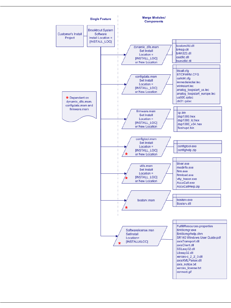
Installation
November 2009 388
Figure 59. Merging Modules into a Single Feature
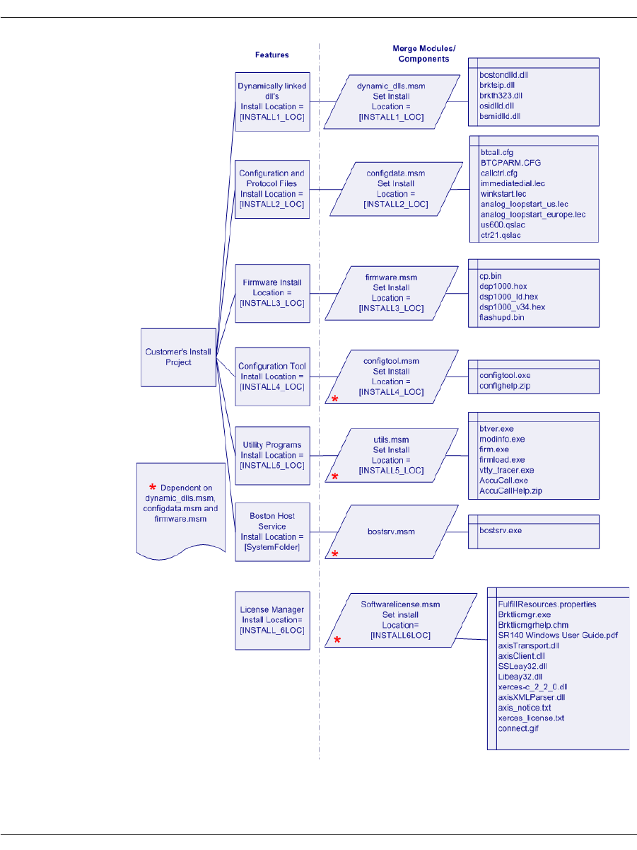
Installation
November 2009 389
Figure 60. Merging Modules into Multiple Features
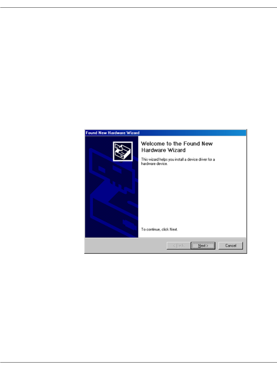
About Plug and Play Components
November 2009 390
About Plug and Play Components
Plug and Play happens outside the process of the application that
uses the drivers. The Brooktrout SDK includes Plug and Play
compatible drivers and the INF file. The INF file contains essential
information needed for the Windows® Class Installers to correctly
identify components in an INF file and install them.
The user installs the hardware in the computer by following the
instructions in the hardware installation guide that comes with the
module. When Windows® starts and the user logs on, the Found New
Hardware Wizard screen appears.
The user selects the option to Search for a suitable driver for my device
and places the software CD in the system (this is a Brooktrout CD or
your application CD with the Brooktrout Plug and Play driver). The
user then browses to the location of the INF files. The Windows®
Plug and Play manager finds the driver and installs it on the
computer.

About Plug and Play Components
November 2009 391
Note: Existing Dialogic® Brooktrout® Fax Products SDK
Developers: You cannot start or stop the Plug and Play driver
using commands like the net start/stop commands that
you might be using in your application. The user cannot restart
the driver since it is now a Windows® Device Manager Plug
and Play driver. For any change requiring a driver restart,
such as change in history size and debug options, you must:
Check for the current state of the service
Tell the user to restart Windows® if the driver is not
started
You can install and uninstall the PnP driver using install.exe
application that is already installed with the Brooktrout Fax
Software.
Dialogic does recommend that the only driver settings that you do
change are the History Enable, and History Size. However, your
changes will only take effect by rebooting the system or by using the
Brooktrout Configuration Tool. You can run the Configuration Tool
in silent mode for the changes to take effect. You do not need to run
it in Advanced mode.
As stated earlier, Microsoft leaves few interfaces for the hardware
vendor to implement. Table 26 summarizes the components for these
interfaces.

About Plug and Play Components
November 2009 392
Plug and Play Installation Scenarios
The following flowcharts show two scenarios that your users might
follow when they install the Brooktrout hardware with your
application. These should help you plan how to link Plug and Play to
your setup schemes and incorporate the Brooktrout configuration
elements.
Table 26. Brooktrout Plug and Play Components
Reference Brooktrout Component
Device Brooktrout hardware
Function Driver boston.sys
INF File trxstream.inf
Device Co-Installer brktBdevco.dll
Device Property Page brktBdevpp.dll
Brooktrout Catalog File brooktrout.cat
Driver Symbol File boston.pdb
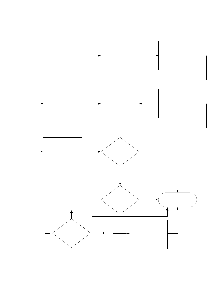
About Plug and Play Components
November 2009 393
Scenario 1 shows the install process beginning with installing the
module. At the end of the process you have created a customized
install process for Brooktrout product components.
User places
Board in server
Plug and Play
Manager finds
board
User opts to
search for driver
files on CD-ROM
Drive or HDD.
[Browses / places
CD in drive]
Plug and Play
Manager calls
trxstream.inf
Plug and Play
Manager creates
"Brooktrout
Hardware" class
Plug and Play
Manager installs
boston.sys
Plug and Play
Manager calls
device co-installer
(brktBdevco.dlll)
Device Co-installer
(brktBdevco.dlll)
receives the call
Is the Brooktrout
System Software
installed?
Yes
Setup
application
found?
No
FINISH
No
Device Co-installer
spawns boston.msi
Yes
Do you wish to install? Yes
No

About Plug and Play Components
November 2009 394
Scenario 2 shows the install process beginning with installing the
software and then installing the module.
User places
Board in server
Plug and Play
Manager finds
board
User opts to
search for driver
files on CD-ROM
Drive or HDD.
[Browses
/
places
CD in drive]
Plug and Play
Manager calls
trxstream.inf
Plug and Play
Manager creates
"Brooktrout
Hardware" class
Plug and Play
Manager installs
boston.sys
Plug and Play
Manager calls
device co-installer
(brktBdevco.dlll)
Device Co-installer
(brktBdevco.dlll)
receives the call FINISH
User installs
Brooktrout software

About Plug and Play Components
November 2009 395
Structure of the Brooktrout PnP Folder
The Brooktrout PnP folder has the following structure:
PnP
| brooktrout.cat
| trxstream.inf
|- TRxStream
| |- x86
| | boston.sys
| | boston.pdb
| | brktBdevpp.dll
| | brktBdevco.dll
| |- x64
| | boston.sys
| | boston.pdb
| | brktBdevpp.dll
| | brktBdevco.dll
Note: It is very important for this folder structure to be maintained
when installed or copied for the Plug and Play to work
correctly. If you change the structure, you must change the
trxstream.inf file.
About the INF File
Brooktrout-supplied INF files (such as trxstream.inf) should be
available in a location readily accessible to Windows®. The INF file
contains important information for Windows® Plug and Play to
work. The primary function is to copy over a driver suitable for the
device that has been discovered. Windows® also offers several
extension activities implemented using the INF file. These activities
can allow the creation of a vendor specific device class, registration
of co-installers, and providing user mode services and device
property pages. We make use of all these features offered by
Windows®.

About Plug and Play Components
November 2009 396
¾
Once you identify the INF file (specifically trxstream.inf), the
following actions occur.
For an authoritative description of the Plug and Play install
process always use information from Microsoft (available at
MSDN).
1. During the hardware installation, Windows® creates a new
device under Computer Telephony Hclass. The Device Manager
lists all Brooktrout hardware devices under Computer Telephony
class/node:
Class = Computer Telephony
Class GUID = {8CF4CA66-A2CC-48FA-BC1D-6A64E47F6D27}
2. Copies the driver files for the identified device to the
system32\drivers folder.
3. Copies the device co-installer and device property page to the
system32 folder.
4. Registers the device co-installer and device property page on the
host system.
5. Installs the device driver(s) if not already installed.
6. Starts the device driver(s).
7. The Plug and Play process then continues with the invocation of
the device co-installer.
About the Dialogic® Brooktrout® Plug and Play Co-Installer
The Plug and Play Device Co-Installer Page is a custom DLL
(brktBdevco.dll) built using a Microsoft provided Setup API.
When a Plug and Play operating system detects any hardware, it
allocates the necessary resources to the hardware (Plug and Play). In
most single function devices or sometimes even multi-function
devices, the devices are ready for use after this process ends.
However in the case of extensible and configurable communications
hardware such as the Brooktrout hardware series, the end user must
configure the module in a separate process before the hardware is
ready for communications applications.
The Plug and Play co-installer provides a page that:
Informs the user that they need to configure the detected
hardware

About Plug and Play Components
November 2009 397
Automatically launches the Brooktrout Configuration Tool
For details about the install package and the configuration tool, see
the installation and configuration guide that came with your
software.
Use the next paragraphs to understand the role that the co-installer
page plays in Plug and Play operating systems.
Displaying the Found New Hardware Page
When the co-installer is registered with the operating system (by
specifying it in the INF file), the Plug and Play Found New Hardware
Wizard process invokes the co-installer for each new device detected
by the operating system. It is up to the co-installer to determine
whether the page needs to be displayed or not. To avoid multiple
displays in a multiple hardware scenario, the co-installer stores a
cookie in the registry the first time it is displayed. The next time the
co-installer callback is invoked, the cookie value is examined to
decide whether the page should be displayed or not. If the cookie is
found and set, then the co-installer page is not displayed.
Should You Launch the Configuration Tool
If you don’t want to ship the configuration tool, specify this choice in
the INF file. The default value is to launch the configuration tool (if
no entry is found or if the entry is found and it is true).
When Should You Launch the Configuration Tool
Premature launch of the configuration tool might lead to providing
misleading information to your user and potential race conditions
that affect the proper functioning of the configuration tool.
Your customer might want to install multiple modules. If you launch
the tool from the co-installer on the first detected module, you might
face race conditions as the configuration tool and the Found New
Hardware Wizard compete for the driver. One or both might also get
inaccurate information for the rest of the modules.
To avoid this problem, the co-installer creates a process level event
in the non-signaled state and launches the configuration tool in a
timer mode (60 seconds: default). The configuration tool waits for the
timeout signal. While setting this mode up, the co-installer page for
the second detected module determines that the page should not be

About Plug and Play Components
November 2009 398
displayed, and it instead signals the process level event. The
configuration tool (upon getting unblocked because the event got
signaled rather than timing out) resets the timer and waits for the
event again. This process continues until the co-installer does not
signal anymore; finally, the configuration tool waiting for the event
times out and then launches the functional user interface.
The configuration tool in the timer mode provides a Launch Now
button that immediately launches the main application to deal with
problems such as:
The user might cancel the Found New Hardware Wizard and the
co-installer might not get invoked.
Or 60 seconds might be too long for the user to wait.
About the Device Property Page
The device property pages are dynamic-link libraries (DLLs) that
work in conjunction with the Device Manager. They typically display
property sheets for examining and modifying the settings and
configuration of a device. The Device Manager provides a default
property page that gives access to typical device properties. The
Device Manager also gives the property page provider an
opportunity to add a custom property page. The custom provider
must be registered in order for the Device Manager to use it.
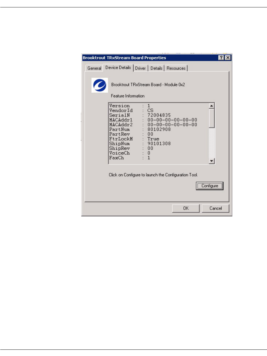
About Plug and Play Components
November 2009 399
The Brooktrout Device Manager Property Page is a custom DLL
(brktBdevpp.dll) that provides basic integration with Microsoft®
Management Console. Its primary function displays feature
information and its secondary function provides the option to launch
the Brooktrout Configuration Tool.

Modifying Configuration Files
November 2009 400
Modifying Configuration Files
This section describes each of the configuration files. You can edit
the configuration files with a standard text editor or you can use the
Brooktrout Configuration Tool to make changes (see the installation
and configuration guide that came with your software).
Assuming the default installation, the configuration files are located
in Brooktrout\Boston\config. Sample configuration files are located
in Brooktrout\Boston\config\samples.cfg.
For details about parameters and valid values, see the Bfv API
Reference Manual, Volume 6, Appendix A, Configuration Files.

Modifying Configuration Files
November 2009 401
User-Defined Configuration File (btcall.cfg)
The user-defined configuration file contains parameters that set
values such as specific fax formatting. The Brooktrout SDK supplies
a default configuration file named btcall.cfg.
If you have a btcall.cfg file created for a previous release of the
Bfv API, delete the following parameters from the file. These
parameters have been removed or moved to another configuration
file as indicated:
Parameters are listed in any order and typed in either uppercase or
lowercase or both. Only one parameter per line is permitted.
Parameters must be separated from their values: a decimal integer,
a hexadecimal integer, or a character string by one or more spaces.
Commas, colons, and dashes are not valid parameter separators. The
default value is automatically supplied for each missing parameter;
and parameters that do not match any of the valid keywords are
ignored. If a parameter appears more than once, the last occurrence
is the one that will take effect.
For details about parameters and valid values, see the Bfv API
Reference Manual, Volume 6, Appendix A, Configuration Files.
Parameter Description
did_digits This DID digit detection parameter has been modified and moved to the
callctrl.cfg file.
did_variable This DID digit detection parameter has been modified and moved to the
callctrl.cfg file.
digital The call control (callctrl.cfg) configuration file replaces the configuration
file defined by the digital parameter.
isdn The call control (callctrl.cfg) configuration file replaces the configuration
file defined by the isdn parameter.
line_encoding The call control configuration file (callctrl.cfg) that replaces the teleph.cfg
file (see Volume 6 of the Bfv API Reference Manual) does not use this
parameter.
nrings This parameter has been renamed num_rings and moved to the callctrl.cfg
file.
switch_hook This parameter has been renamed flash_hook_duration and moved to the
callctrl.cfg file.
teleph The call control (callctrl.cfg) configuration file replaces the configuration
file defined by the teleph parameter.

Including the Brooktrout Configuration Tool
November 2009 402
Call Control (callctrl.cfg) Configuration File
This file contains configuration parameters that define how you
want the Bfv API to configure the modules for call control.
For details about parameters and valid values, see the Bfv API
Reference Manual, Volume 6, Appendix A, Configuration Files.
Including the Brooktrout Configuration Tool
When you decide to include the Brooktrout Configuration Tool in
your application, you can launch it in different modes depending on
your customer needs. The tool provides the following modes:
Advanced Mode
Offline Mode
Silent Mode
Timer Mode
Wizard Mode
Note: The Brooktrout Configuration Tool initializes the default
location of the configuration, protocol, and firmware files using
the Registry entries created by the installation. See Registry
Entries on page 373. However, if you decide to ship the tool
separately, then you need to create a custom settings.cfg file
that the configuration tool can use. Refer to the install and
configuration guide for more information.
For details on these modes and running the Brooktrout
Configuration Tool in the various modes, see the installation and
configuration guide that came with your software).

Downloading Firmware Files
November 2009 403
Downloading Firmware Files
In addition to installing the software, you must:
Update the boot ROM flash memory
Download the firmware files
Optionally configure the call control parameters.
The Configuration Tool can only be used to start the Boston Host
Service and to configure the call control parameters; this utility
cannot be used to update the boot ROM flash memory.
Use the instructions in your installation and configuration guide to
manually update the boot ROM flash memory and download the
firmware files.
Use the Brooktrout Configuration Tool to configure the call control
parameters (see your installation and configuration guide), or
manually edit the callctrl.cfg file included in your Brooktrout SDK.
For details about the call control parameters and valid values, see
the Bfv API Reference Manual, Volume 6, Appendix A, Configuration
Files.

Removing Software
November 2009 404
Removing Software
The Add/Remove Programs selection on the Windows® Control Panel
screen provides options to initiate the following on the installed
components for the package (see Uninstalling or Modifying the
Software in the installation and configuration guide that came with
your software):
Modify – Selecting this option displays a custom setup dialog that
allows the user to select the features to be installed or removed. This
option is helpful if the user wants to install features that were not
selected to be installed during the first installation.
Repair – Selecting this option should do the following:
Repair all runtime components that are currently installed on
the user system
Re-install some of the files that might have been deleted,
renamed, or moved
Replace missing registry entries and shortcuts.
Note: Windows® MSI framework can only detect file corruption if
the file is tagged as a KEY file. Only critical files in the
installation package are tagged as such. All the runtime
binaries that are installed by Brooktrout SDK and are tagged
as KEY files.
Remove – This option should remove the package, including all the
files that were copied over by the installation. This option only
deletes the files that were created or copied by the installation. It
should remove bostsrv.exe service and delete all registry entries
created for this service. It should also remove all the registry entries
that were created by applications such as the Brooktrout
Configuration Tool.
On Plug and Play operating systems, you must completely remove
the Plug and Play driver by following the instructions in Removing
the Plug and Play Driver on page 405.
Note: The group responsible for maintaining the install project
MUST be notified of any registry entries, files, folders, services
and shortcuts that should be removed through the
Add/Remove Programs process.

Removing the Plug and Play Driver
November 2009 405
Removing the Plug and Play Driver
Installing a Brooktrout device using the Plug and Play Manager
(Found New Hardware Wizard) creates some backup files and registry
entries. The Windows® Plug and Play Manager uses this
information to automatically install the device on rebooting.
To completely remove the Plug and Play driver from the system, you
must perform a complete cleanup after you remove the device from
the Device Manager.
Make sure you stop all your applications and the Boston Host Service
before uninstalling the device driver.
Note: The following instructions include steps to take when
removing the Plug and Play driver for versions earlier than 5.2
and for removing the Plug and Play driver for the 5.2 version.
For Earlier Versions (Prior to 5.2)
¾
To remove an earlier version of the Plug and Play driver:
1. Open Windows Device Manager.
2. Expand the Brooktrout Hardware node.
3. Right-click the board node and select Uninstall.
4. Uninstall all the Brooktrout boards listed under the Brooktrout
Hardware node.
5. Open Command Prompt and type “net stop boston” to stop the
Boston driver that might still be running.
6. Delete the following files:
C:\WINNT\SYSTEM32\DRIVERS\boston.sys
C:\WINNT\SYSTEM32\brktBdevpp.dll
C:\WINNT\SYSTEM32\brktBdevco.dll
7. Examine the registry value InfPath located under
HKEY_LOCAL_MACHINE\SYSTEM\CurrentControlSet\
Control\Class\{50CE2010-E61B-40EF-9EAA-
2BCDE74F8C6C}\0000.

Removing the Plug and Play Driver
November 2009 406
This value contains the name of the backup copy of the
trxstream.inf file that Windows® created during device
installation under C:\WINNT\INF.
8. Delete the INF file of this name from C:\WINNT\INF along with
the corresponding PNF file.
Except for the extension, the INF file and the PNF file have the
same names. For example, if the INF file is oem11.inf, the name
of the PNF file is oem11.pnf.
9. Delete the following registry keys:
HKEY_LOCAL_MACHINE\SYSTEM\CurrentControlSet\
Control\Class\{50CE2010-E61B-40EF-9EAA-
2BCDE74F8C6C}
HKEY_LOCAL_MACHINE\SOFTWARE\Brooktrout
Technology\DeviceCoInstaller
HKEY_LOCAL_MACHINE\SOFTWARE\Brooktrout
Technology\DevicePropertyPage
HKEY_LOCAL_MACHINE\SYSTEM\CurrentControlSet\
Services\boston
10. Reboot the system and verify that the Brooktrout Hardware node
is not listed in the Device Manager.
For Version 5.2
¾
To remove the Plug and Play driver:
1. Open Windows Device Manager.
2. Expand the Computer Telephony node.
3. Right-click the Brooktrout TRxStream board node and select
Uninstall.
4. Uninstall all the Brooktrout boards listed under the Computer
Telephony node.
5. Open Command Prompt and type “net stop boston” to stop the
Boston driver that might still be running.
6. Delete the following files:
C:\WINNT\SYSTEM32\DRIVERS\boston.sys
C:\WINNT\SYSTEM32\brktBdevpp.dll
C:\WINNT\SYSTEM32\brktBdevco.dll

Removing the Plug and Play Driver
November 2009 407
7. Examine the registry value InfPath located under
HKEY_LOCAL_MACHINE\SYSTEM\CurrentControlSet\
Control\Class\{8CF4CA66-A2CC-48FA-BC1D-
6A64E47F6D27}.
8. Search for the first key which contains the following values:
DriverDesc=Brooktrout TRxStream Board
This key should contain the name of the backup copy of the
trxstream.inf file that Windows® created during the device
installation under C:\winnt\INF
9. Delete the INF file of this name from C:\WINNT\INF along with
the corresponding PNF file.
Except for the extension, the INF file and the PNF file have the
same names. For example, if the INF file is oem11.inf, the name
of the PNF file is oem11.pnf.
10. Delete the following registry keys:
For 32-bit operating system:
HKEY_LOCAL_MACHINE\SOFTWARE\Brooktrout Technology
\DeviceCoInstaller
HKEY_LOCAL_MACHINE\SOFTWARE\Brooktrout Technology
\DevicePropertyPage
HKEY_LOCAL_MACHINE\SYSTEM\CurrentControlSet
\Services\boston
For 64-bit operating system:
HKEY_LOCAL_MACHINE\SOFTWARE\WOW6432Node
\Brooktrout Technology \DeviceCoInstaller
HKEY_LOCAL_MACHINE\SOFTWARE\WOW6432Node
\Brooktrout Technology \DevicePropertyPage
HKEY_LOCAL_MACHINE\SYSTEM\CurrentControlSet
\Services\boston
11. Reboot the system and verify that the Brooktrout TRxStream
node(s) is not listed under Computer Telephony class node in the
Device Manager.

November 2008 408
Appendix A
G3 Legacy Utilities
This appendix describes legacy utilities that help manipulate raw
G3 fax files.
The utilities described in this chapter permit you to manipulate
raw G3 fax files (rather than infopkt-formatted files) from the
command line. These are legacy utilities that are provided to
users who need to manipulate raw G3 files. They have been
tested with previous versions of the Bfv API and are expected to
work, but they are no longer tested/supported.
Output files will usually contain a 128-byte Brooktrout header.
When you create an infopkt file using one of these output files,
you must either use the BTG3 type infopkt or remove the
header.
For input files, the 128-byte Brooktrout header is optional.
However, a header can provide crucial information to the
utilities about resolution and image width. This information is
particularly important to the Print utility.
The G3 utilities only support the resolutions 200H x 100V
(Normal) and 200H x 200V (Fine). They do not support any of
the higher resolutions.
All utilities except for the G3 conversion utility use file names
with the .3XX extension. The first page of a fax has the extension
.301, the second .302, etc. Many of these utilities will ignore
actual extensions supplied and add or convert to these
extensions.

November 2009 409
The G3 utilities include:
ASCII to Fax Conversion
Utility Converts ASCII text files to Brooktrout G3 fax image files.
Cut and Paste Utilities Used in conjunction, removes parts of fax images and stores them in
a separate file and recombines them into another file.
Epson to Fax Conversion
Utility Converts Epson print files to Brooktrout G3 fax image files.
Fax Display and Edit Utility Displays fax files and provides a visual interface to the cut utility.
G3 Conversion Utility Converts raw fax files between any of these formats – MH, MR,
MMR, PCX, and bitmap.
Print Utility Prints fax files to any of several printers.
An example of how to use each utility and its parameters is included
with each description.
All utility executable programs are found in the
Brooktrout/boston/bfv.api/<platform>/utils/bin.
Note: For the operating system you are using, substitute its name for
<platform> in the following instructions and use the
appropriate location where the installed files are located (that
is, /usr/sys for UnixWare, Solaris, and Linux; and C: for
Windows®.

ASCII to Fax Conversion Utility (asctog3)
November 2009 410
ASCII to Fax Conversion Utility (asctog3)
Converts ASCII text files to Brooktrout Group 3 fax image files.
Although this utility is included, in most cases ASCII file
transmission is better accomplished utilizing the ability of the
Brooktrout fax modules to convert ASCII to G3 on-the-fly. This is a
legacy utility.
Command Syntax
asctog3 argument-list
Where:
The ASCII to Fax Utility displays help information on ASCII to
Group 3 file conversion when no arguments are specified. For
example:
asctog3 -imemo.txt -fibmpcps.fnt
converts a text file named memo.txt to a Group 3 fax file using a
standard 80 column font.
-i (input file) Specifies the input file to convert to Group 3.
-o (output file) Specifies the output filename. If omitted, an
output file is created with the same input filename but is
given a .3XX file extension.
-mfine (fine resolution) Specifies fine (200 vertical lines/inch)
resolution. The default is normal resolution (100
lines/inch).
-margin# (margin) Adds a left margin specified in tenths of an inch
(#). Width is optional and defaults to either 0.5 inch, if the
-margin option is specified, or to 0 if the -margin option
is not specified.
-f (font file) Species the font file to use for the conversion.
-lines# (page length) Specifies the page length in terms of text
lines. Defaults to 66 lines/page for standard 11'' paper.
-nopad (no pad) Prevents padding short pages to standard 11"
page length. The default pads short pages to 11" length,
regardless of the input file.
-skip# (letterhead) Makes the first page of output shorter by #
text lines. Leaves room for a letterhead.
-w# Makes lines of the specified width: 0 = A4, 1 = B4, 2 = A3.

Cut and Paste Utilities
November 2009 411
Cut and Paste Utilities
The next two utility commands, g3chop and g3combin, permit
cutting and pasting of fax images at the command line. These two
commands are most commonly used to create letterhead and
signature files.
Cut Utility (g3chop)
Removes portions of Brooktrout Group 3 fax files and stores them in
a separate file.
Command Syntax
g3chop -sx -cy -ifile1.301 -ofile2.301
Where:
For example:
g3chop -s5 -c20 -isalute.301 -oadvert.301
skips the first five lines of the file salute.301, chops the next 20 lines,
and puts them into the output file advert.301.
-s (start chop) Specifies the distance in 1/10" units, from
the top of the file, to skip before chopping.
-c (chop size) Specifies the distance in 1/10" units to chop.
-ifile1.301 (input file) Specifies the name of the file to chop.
-ofile2.301 (output file) Specifies the name of the output file which
contains the resulting chopped file.
-l (lines) Changes the -s and -c arguments to work with
G3 lines as the units.
The number of lines are calculated in inches using the
file resolution if you know how far down in inches you
want to start and you use the -l argument: to skip 2
inches from the top of the file in normal resolution, skip
200 lines; for fine resolution, skip 400 lines.
The number of lines to chop can also be calculated based
on the file resolution and the number of inches to remove
from the file.

Cut and Paste Utilities
November 2009 412
Paste Utility (g3combin)
Combines portions of Brooktrout Group 3 fax files, and, although it
is most commonly used to create letterhead and signature files, it
can combine all types of fax files. Although this utility is included, in
most cases combining fax files is better accomplished using infopkt
files.
To attach a letterhead, specify the letterhead file as file1. To attach a
signature file, specify the signature file as file2. If the resolution of
the two files is different, you can specify which resolution to use for
the output file.
Command Syntax
g3combin <file1.301> <file2.301> <file3.301> [-l] [-s] [-pad]
Where:
For example:
g3combin -1 lethd.301 sign.301 busrpt.301
combines the contents of lethd.301 with the contents of sign.301 into
the output file busrpt.301. The contents of lethd.301 (letterhead) is
placed at the top of the output file, and sign.301 (signature) is placed
at the bottom of the output file. The resolution of sign.301 is
assigned to the output file busrpt.301.
-l (file2 resolution) Specifies the resolution of file2 for the
resolution of the output file when the resolutions of the
input files are different.
-s (file1 resolution) Specifies the resolution of file1 as the
resolution of the output file when the resolutions of the
input files are different.
file1.301 (top input file) Specifies the name of the file to place on top
of the combined document.
file2.301 (bottom input file) Specifies the name of the file to place on
the bottom of the combined document.
file3.301 The output file containing the combined contents of
file1.301 and file2.301.
-pad (pad short pages) Pads short pages to a standard 11" page
length.

Epson to Fax Conversion Utility (epstog3)
November 2009 413
Epson to Fax Conversion Utility (epstog3)
Converts Epson print files to Brooktrout Group 3 fax images and
provides complete emulation of the Epson-LX80 printer (including
bold, italics and graphics).
Command Syntax
epstog3 argument-list
Where:
-i (input file) Specifies the input printer file
(Epson-format) and optional path name.
-o (output file) Specifies the output fax image filename
and optional pathname.
-mfine (fine resolution) Specifies fine (200 vertical lines/inch)
resolution. The default is normal resolution (100
vertical lines/inch).
-132 (132 column) Scales printer files that contain wide
(132 column) documents, spreadsheets, or
multicolumn word processed documents so they fit on
standard 8.5" x 11" paper.
-margin# (margin) Adds a left margin specified in tenths of an
inch. Width is optional and defaults to either 0.5 inch,
if the -margin option is specified, or to 0 if -margin
option is not specified.
-fibm (emulation) Changes the default printer emulation
from an Epson to an IBM graphics printer. This, in
effect, changes the font used when converting text
data.
-lines# (page length) Specifies the page length in terms of text
lines. Defaults to 66 lines/page for standard 11'' paper.
-nopad (no pad) Prevents padding short pages to a standard
11" page length. The default pads pages to an 11" page
length, regardless of the length of the input file.
-skip# (letterhead) Makes the first page of output shorter by
# text lines. Leaves room for a letterhead.

Epson to Fax Conversion Utility (epstog3)
November 2009 414
The epstog3 utility displays help information on converting graphics
files to fax image files, on the command line.
Note: Fonts must be located in the current directory for all platforms
except those platforms that use MS-DOS executables
(Windows® NT, Windows® 2000). For these cases, the fonts
must be located either in the font subdirectory of the directory
named by the FMAIL environment variable, if it is set, or in the
boston\bfv.api\fonts directory.
For example:
epstog3 -icap001.epc
converts a graphics file named cap001.epc to a Group 3 fax image
file.
If the output filename is not specified, it is automatically created
using the input filename and given an extension of .3XX.
If the input file does not reside in the current or default directory,
the path name must also be specified.
If the path name of the output file is not specified, the output file is
placed in the same directory as the input file.

Fax Display and Edit Utility: Supershow (ss)
November 2009 415
Fax Display and Edit Utility: Supershow (ss)
Displays a fax file on screen for viewing and editing. Editing options
include scaling, rotating, and reversing video.
Note: Supershow does not scale images automatically to maintain
aspect ratios or to fit images on the screen. Each pixel in the
file corresponds to one pixel on the screen. Supershow does
support manual scaling with the commands described on the
help screen.
To see a complete list of arguments and display options, type ss
without any arguments at the system prompt. To access the
Supershow help screen, which lists movement and display
commands, press the? key during a fax display.
Note: The Bfv API does not provide this utility under Solaris. The
version of this utility supplied for UnixWare will not run under
X Windows.
Supershow automatically determines the adapter type, so the -h and
other display-related arguments are optional on all environments.
Use these arguments to select a display mode that differs from the
default for the current adapter type.
All arguments are optional, except -i.
Command Syntax
ss[-[r][h|c|e|v|ea|va]][-xs#][-ys#][-x#][-y#][-w#][-m#] -ifilename
Where:
-r Displays the image in reverse video. You can combine
this argument with one of the other arguments: h, c,
e, v, ea, or va.
-h Forces the display type to Hercules graphics.
-c Forces the display type to IBM CGA.
-e Forces the display type to IBM EGA.
-v Forces the display type to IBM VGA.
-ea Forces the display type to IBM EGA alternate mode.
-va Forces the display type to IBM VGA alternate mode.
-ifilename Specifies the name of the fax file to display.

Fax Display and Edit Utility: Supershow (ss)
November 2009 416
For example:
ss -rv -iletsig.301
displays a file named letsig.301 on the screen in reverse video on a
PC equipped with a VGA adapter.
-x Specifies the X-offset. Units are in tenths of an inch.
-y Specifies the Y-offset. Units are in tenths of an inch.
-xs Specifies the X scale factor. Values are 1, 2, or 3.
-ys Specifies the Y scale factor. Values are 1, 2, or 3.
-w Specifies the width (0 = A4, 1 = B4, 2 = A3) and
overrides the header.
-m Specifies the number of kilobytes of memory to use for
an image. The default is 512K. Using large values
might slow response times. (This argument is not
available for Windows® NT.)

G3 Conversion Utility (g3cvt)
November 2009 417
G3 Conversion Utility (g3cvt)
Converts a raw fax file between any of these formats—MH, MR,
MMR, PCX, and bitmap. It accepts files that use either MSB or LSB
bit order, and (optionally) skips past a Brooktrout 128-byte header.
Output from this utility does not contain a 128-byte Brooktrout
header.
As it proceeds, g3cvt displays dots across the screen. If it detects an
error in the input file, g3cvt displays an error message. With some
input formats, g3cvt cannot continue after it encounters an input
error.
For bitmap conversion, this utility uses raw bitmap format. The -w
option determines the number of bits per line, and the -b option
determines the bit order. Raw bitmap format does not use
start-of-image, end-of-line, or end-of-image marks.
When decoding MH or MR files, if this utility encounters an input
line with errors, it writes a copy of the previous line in the output
file.
To display usage information, type g3cvt without any arguments.
Command Syntax
g3cvt <i_fmt> <i_file> <o_fmt> <o_file> [options]
Where:
i_fmt Format of the input file—MH, MR, MMR, PCX, or BIT.
i_file Name of the input file.
o_fmt Format of the output file—MH, MR, MMR, PCX, or BIT.
o_file Name of the output file.
Options
-w<width> Specifies the width of the lines; A4 (default), B4, or A3.
-b<b_o> Specifies the bit order of both the input and output files –
M (MSB), the default, or L (LSB).

G3 Conversion Utility (g3cvt)
November 2009 418
For example:
g3cvt MMR fax.mmr MH fax.mh
converts a fax file from MMR format to MH format.
-h Causes g3cvt to copy the first 128 bytes of the input file to
the output file, with no conversion.
-f Specifies fine resolution input. Used with MR or PCX
output only.
MR output—The program represents the data slightly
differently and more efficiently when it knows the input
is in fine resolution.
PCX output—Since PCX format is always in fine
resolution, the program must know whether the input file
is in fine or normal resolution. If the input is in normal
resolution, the program doubles each line in the output
file.
A PCX input file automatically activates the -f option.

Print Utility (p)
November 2009 419
Print Utility (p)
Prints the fax file to any one of several printers.
Command Syntax
p argument-list
p [-ppmode] [-xXOFF] [-yYOFF] [-xsXSCALE][-ysYSCALE] -ifiles [-ooutfile]
[-paper[A4/LET]] [-w[width]]
Where:
-ppmode (print mode) Indicates the printer and resolution to use
for printing: where pmode is the character string that
defines the print mode and is one of the following:
psd Single density: 60 dpi
plsd Low speed double density: 120 dpi
phsd High speed double density: 120 dpi
pqd Quadruple density: 240 dpi
pqds Low speed quadruple density: 240 dpi
peps Epson QX-10 mode: 80 dpi
poto One-to-one plotter: 72 dpi
pd90 90 dpi
pibmprosd IBM Proprinter single density
pibmprolsd IBM Proprinter low speed double
density
pibmprohsd IBM Proprinter speed double density
pibmproqd IBM Proprinter quadruple density
pljl HP Laser Jet: 75 dpi
pljm HP Laser Jet: 100 dpi
pljh HP Laser Jet: 300 dpi
plj2l HP Laser Jet II: 75 dpi
plj2m HP Laser Jet II: 100 dpi
plj2h HP Laser Jet II: 300 dpi
pnec NEC P6 24-Nadel Drucker: 360 dpi
pnec0 NEC P6 24-Nadel Drucker: 180 dpi
pfx2000 Axiom Edwards FX-2000: 200 dpi
-xXOFF (x offset) Selects an X direction offset in tenths of inches.
Only the portion of the image to the right of this position
is displayed.

Print Utility (p)
November 2009 420
The Print Utility displays help information when no arguments are
specified.
Note: The Print utility automatically scales the image to maintain
the correct size and aspect ratio for each supported printer
type and resolution. If the Print utility encounters a 128-byte
header at the beginning of the input file, it uses the actual
resolution of the fax for scaling; otherwise, it uses normal
resolution for scaling.
Note: When using widths larger than the standard A4, you do not
need to include the -w argument. However, because these
larger widths exceed printers’ standard width, the Print utility
truncates the image horizontally to fit the standard width. If
you do include the -w argument, the Print utility reduces the
size of the image to fit the standard width.
For example:
p -phsd -xs10 -ys10 -idemo.301
prints a file, demo.301, on an Epson/IBM compatible printer in high
speed, double density mode scaling the image in both the x and y
directions to one-half size.
-yYOFF (y offset) Selects a Y direction offset in tenths of inches.
Only the portion of the image below this position is
displayed.
-xsXSCALE (x scale factor) Selects an X direction scale factor in 5%
increments. The image is scaled to this factor of its
original size in the X direction.
-ysYSCALE (y scale factor) Selects a Y direction scale factor in 5%
increments. The image is scaled to this factor of its
original size in the Y direction.
-ifiles (input filename) Specifies the Group 3 files to print. The
filename and pages to print are specified: filename (first
page, last page).
-ooutfile (output filename) Directs output to the specified file
rather than the printer.
-paper (paper type) Specifies the paper size to use.
-w[width] Scales horizontally and vertically to fit an image of the
specified width: 0 = A4, 1 = B4, 2 = A3. If no width is
specified, this utility uses the width from the 128-byte
Brooktrout header.
A4 Specifies an A4 feeder and A4 size paper.
LET 8.5" x 11" standard size paper.

November 2008 422
Appendix B
Recompiling On Linux Platforms
This appendix provides instructions for recompiling the Boston
driver to support new kernel patches.
Use the instructions below to recompile the Boston driver on
supported Linux platforms so that the driver can operate with
any kernel patch for supported Linux versions. The Boston
driver supports only official kernel patches as released by Red
Hat. After you follow the procedure, the driver supports only the
exact version of the kernel currently running on your system,
including architecture and variant.
Note: This feature only provides support for the Boston driver,
the kernel mode code. Other parts of the Brooktrout SDK
(the user mode code) might also need rebuilding, and this
feature will not help in these situations.
Supported versions include:
Redhat Enterprise Linux ES/AS 4.0 and 5.0
The fully precompiled installable driver binaries reside under
the driver/linux/kernel/kvers directory. This directory contains
subdirectories corresponding to each kernel version, variant, and
architecture, with a driver binary in each (named boston.o or
boston.ko).
For each Linux OS version supported, the only precompiled
driver supplied supports the original kernel that shipped with
that version of Linux.

November 2009 423
Each of these directories also contains a file named bostbase.a, which
is a library containing precompiled object files compiled for that
same kernel version, variant, and architecture.
The driver/linux/kernel directory contains files named kerndep.c,
kerndep.h, and makefile.kerndep.
Before building a Brooktrout driver for a patch version, install the
kernel source, the compiler, and other standard development tools
on the system.
¾
To build a driver for a kernel patch version, enter the following
at the command prompt:
make -f makefile.kerndep
This command performs several steps.
Determines what the base RedHat release is that the booted
kernel is based on, what the kernel version is that
corresponds to the base release, and what the variant and
architecture are.
Compiles the source file kerndep.c on the current booted
kernel setup.
Links the resulting object file with the bostbase.a file from
the directory corresponding to the base kernel version for the
current variant and architecture.
Puts the resulting driver binary into an appropriate kvers
subdirectory for the actual kernel version in use.
After compiling the driver, use the standard manual dinstall script
provided on the CD to manually configure the driver.
If the kernel source is not installed in a standard location, use the
optional KERNEL_SOURCE=<dir> command line option to specify
the kernel source location to the make utility.
For Red Hat Linux releases ES/AS 3.0 and earlier:
The kernel source is the package whose name is of the form
kernel-source-<version>, in the file kernel-source-<version>.i386.rpm.
This package is automatically installed if you tell the Linux
installation program to install everything.

November 2009 424
For Red Hat Linux releases ES/AS 4.0 and later:
The kernel source itself is not required; instead, a development kit is
required. This kit is in the package whose name is of the form
kernel-devel-<version>, in the file kernel-devel-<version>.i686.rpm or
kernel-smp-devel-<version>.i686.rpm. This kit is automatically
installed if you tell the Linux installation program to install
everything. In this case, KERNEL_SOURCE should point to the
appropriate subdirectory of /usr/src/kernels which would normally
be one of <version>-i686 or <version>-smp-i686.
Linux Directory Structure
The directory structure created when you install the Bfv API is
based on the Linux compiler version:
Directory 3.4 contains files for Enterprise Linux ES/AS 4.0
Directory 4.1 contains files for Enterprise Linux ES/AS 5.0
Refer to the Dialogic® Brooktrout® Fax Products SDK Installation
and Configuration Guide for the details of each directory.

November 2009 426
Glossary
API Application Programming Interface
ASR Automatic Speech Recognition
Channel A logical channel of operations provided by a Boston module. See
logical channel number, ordinal channel number, work channel.
EC Echo cancellation
External-Telephony
Mode Using the Bfv API directly instead of a speech engine API to
perform call control (Mixed Mode)
Facility A software entity responsible for a set of related functions that
provide services to the host, e.g., fax facility and voice facility.
HDLC High level Data Link Control
ISDN Integrated Services Digital Network
IVR Interactive Voice Response

November 2009 427
lapdid The term lapdid has its origins with the LAP-D protocol used for call
control, but has an extended meaning for Brooktrout products. For
call control for all protocols, trunk 1 = lapdid 0, trunk 2 = lapdid 2,
trunk 3 = lapdid 4 and trunk 4 = lapdid 6.
LEC Local Exchange Carrier
Line A T1/E1 slot or a single analog slot. Lines are numbered starting at
1.
Logical channel number A number used with the hardware module number to reference a
channel in a system. Channel 0 is reserved and channel 1 is the
administrative channel. Other channels are numbered from
2 to n+1 (where n is the number of work channels defined for the
module).
Millennium Address An address of a communicating Boston or Millennium entity such as
a facility and channel on a Boston module or the Boston device
driver. Each address consists of 4 components, the facility, the
channel, the module, and the machine. It is possible to make use of
most features of the firmware and the APIs without requiring direct
use of these addresses.
Module A communicating Boston entity that usually represents a CPU on a
Brooktrout board, a host application, or the Boston driver. See
section TBS for more information about modules and module
number assignment.
NVRAM Non-Volatile RAM. Random Access Memory that is not erased when
the board is powered off or when the firmware is downloaded again.
Ordinal channel number A number in the range 0 to n-1 where n is the total number of work
channels on all the boards in the system.
Packet In the Boston architecture, a sequence of bytes containing a Boston
destination address, source address, and one or more commands.
PCI Peripheral Component Interconnect
PDF Portable Document Format
Port A TDM bus (MVIP, H110, etc.) or a DS-1 interface (T1/E1).
RBS Robbed-Bit Signaling

November 2009 428
Stream A logical data entity that corresponds to a physical data line on a
TDM bus.
T1/E1 span The set of slots that comprises one T1 (24) or one E1 (30) line. The
spans are numbered starting at 1.
TCP Transmission Control Protocol
Time slot A logical entity that corresponds to one telephone call.
Unit number 1. In telephony configuration files and functions, a unit is a
hardware port on a Brooktrout board and is numbered starting at 0
(to denote a TDM bus); from 1 to n (for a specific T1/E1 interface).
2. In some Bfv functions (e.g., BfvLineAttach), an ordinal channel
number. Its range is 0...n-1, where n is the number of channels in a
system.
VAD Voice Activity Detection
Work channel One of the channels on a module that is available for
non-administrative purposes as a result of downloading firmware. A
module configured for 48 channels when firmware download is
performed has 48 work channels and one administrative channel.
Logical work channel numbers start at 2 on each module.

430
A
About merge modules 376
Accessing the telephone system 36
Active redirecting for Japan (call transfer) 187
Add/Remove Programs
Removing packaged software 404
Administration, management and configuration Bfv
functions 26
Administrative channels 30
ALERTING Q.931 message 318, 321
API debug mode 92
parsed commands in output 98
app.src directory 127
Applications
accessing infopkt streams from 83
accessing TIFF-F files 87
developing using Bfv API 56
fax status information from 89
remote logging 134
Turning on remote logging 134
Argument structures 34
ASCII fonts
downloading 150
ASCII to fax (asctog3) conversion utility 410
ASR, two-channel call transfers 190
Audio conferencing
API 24, 40
B
bapp.src directory 127
B-channel negotiation 318
Bellcore standards 109
Bfv API 23
call control 36
functions 26
introducing 22
libraries 25
BfvCallSWClearConns
Two-channel call transfers 192
BfvCallSWConnect
Connecting and disconnecting resources for two-
channel call transfer 193
Two-channel call transfers 192
BfvCallSWGetConns
Two-channel call transfers 192
BfvCallSWGetInfo
Two-channel call transfers 192
BfvLineTransfer 177, 202
BfvLineTransferCapabilityQuery 177
Board
monitoring condition 127
status and monitoring functions 33
boardmon program 127
Boston Host Service 384
Boston Simple Message Interface (BSMI) API 23
boston.msi file
Defining properties 368
Spawning software installation package 364
brktBdevpp.dll
Packaging 399
Brooktrout Configuration Tool 374, 380, 381
Brooktrout License Manager 382
Brooktrout software
Index

November 2009 431
Checking for presence of 369
BSMI API
Boston Simple Message Interface 23
call control 36
control messages 37
BT_CPARM.CFG file 32
btcall.cfg
configuration files 32
Modifying for packaging software 401
BTLINE structure 25, 28
btver program
debugging tool 100
using 129
C
call clearing
initiated by the board 323
initiated by the network 325
Call control 36
Bfv API 36
BSMI API 36
call progress signals 38
CALL PROCEEDING Q.931 message 318, 321
Call switching connections
listing 130
Call transfer
Monitoring 190
Recording 190
CALL_RES structure 34
Changing driver settings
Packaging 391
Channel
definition 426
numbering 30
storing information 28
Circuit-switched call control
Bfv API functions 26
Command/Response (C/R) bit 103
Communication between Brooktrout board and
T1/E1 ISDN lines 36
Compiling sample applications
Developer Studio Project files 172
Configuring
call transfers for echo cancellation 195
files 32
firmware for packaging software 403
functions 31
modifying btcall.cfg for packaging software 401
Modifying for packaging software 400
showing parameters 158
CONNECT ACKNOWLEDGE Q.931 message 318,
321
CONNECT Q.931 message 318, 321
Connecting resources
Two-channel call transfers 191
connlist program 130
debugging tool 100
Converting
DCX to raw PCX format 138
infopkt to raw data 151
Country-specific parameters file 32
csend program 131
Cut utility (g3chop) 411
D
Data infopkts 45
D-channel message header 105
DCX
converting to raw PCX format 138
creating files 152
deact program 132
Deactivating a hardware module 132
Deallocating a BTLINE structure 28
debug_control program 134
Debugging
and error handling functions 33
Debugging tools
API debug mode 92
BfvDataFSK 92
BfvLineDumpStructure 93
Dump History utility 93
utilities 100
decode program 135
Defining Registry entries 384
Delay dial signaling 278, 280
Detecting and displaying incoming tones 161
Developer Studio Project files, for compiling sample
files 172
Developing applications 56
Device class, packaging 396
Device Property Page
Packaging software 398

November 2009 432
dfax program 136
Diagnostic utilities, tracing messages 101
Dialing
restrictions 137
dialing
ISDN overlapped 323
Dialing database functions 137
digits
dial pulse 269, 270
timers 268
DISCONNECT Q.931 message 323, 325
Disconnecting resources
Two-channel call transfers 200
Distributing software
Installation package 364
dlfax program 136
Downloading
ASCII fonts 150
feature set data 146
firmware 148, 149
driver recompiling for different Linux versions 422
dstrip program 138
DTMF tones
detecting and displaying 161
detection and generation 38
Dump history
interpreting the output 96
parsed commands in output 98
utility 95
utility program 93
E
eccllvoice program 139
Echo cancellation
Configuring for two-channel call transfer 195
Two-channel call transfers 194
Epson to fax (epstog3) conversion utility 413
Euro-ISDN
dialing long numbers 323
Examples
I Frame header 104
Information Elements 107
merging modules 387–389
Message header 105
Explicit call transfer (ECT) 188
F
Facility
definition 426
Fax 23
application for sending 131
display and edit utility (ss) 415
functions 40
infopkt parameters 52
remote node parameters 89
sending
channel to channel 62
from external fax 63
sending and receiving 141, 152
status information 89
Fax over IP 214–255
Call Control 216
Call Progress Values 225
debug_control mode 243
INVITE message sample 248
Receiving faxes 241
Sample INVITE Request 222
Sending faxes 241
Troubleshooting 243
fax program 62, 140
faxhl program 141
faxll program 142
faxml program 144
faxp program 145
faxpml program 145
Feature Group B 281
Feature Group D 281
Feature program 146
Feature set data 146
File format manipulation functions 42
Files
configuration 32
locations 373, 384
firm program 148
firmload script 149
Firmware
Configuring for packaging software 403
downloading 148, 149
functions and macros 31
Fixed pause signaling 288
font program 150
Frame Check Sequence (FCS) 104

November 2009 433
full duplex call transfer, see Two-channel call
transfers
Functions
administration and initialization 27
board status and monitoring 33
configuration 31
debugging and error handling 33
fax 40
file format manipulation 42
firmware 31
high-level 40
high-level fax 41
low-level 40
low-level fax 41
mid-level 40
mid-level fax 41
miscellaneous 35
FXO signaling 289
FXS signaling 289
G
G3 Conversion Utility 417
G3 utilities 408
ASCII to fax conversion utility(asctog3) 410
cut (g3chop) 411
Epson to fax conversion utility(epstog3) 413
fax display and edit (ss) 415
g3 conversion (g3cvt) 417
paste (g3combin) 412
print (p) 419
g3chop cut utility 411
g3combin paste utility 412
glare 271
Guard timing 325, 326
H
H.323
Address Forms 227
E.164 Alias 228
ID Alias 228
Introduction 226
IP Address 227
Hardware
channel 30
test 49
Hardware module
deactivating 132
listing information 156
High-level functions
receiving a fax 65
sending a fax 64
using 64
Hookflash transfer 180
Analog loop start signaling 180
L4L3mTX_HOOKFLASH 181
T1 and analog BSMI applications 181
T1 Robbed Bit 180
I
I Frame header example 104
Immediate start signaling 286
Incoming call
timing diagram for E&M Immediate Start 286
timing diagram for E+M Wink Start/Delay Dial
278
Indirect infopkts 45
INF file, Packaging 395
Infopkt streams 47
accessing from applications 83
building files 153
creating 47, 48, 50
decode utility 135
sending TIFF-F files within 84
Infopkt structure 50
Infopkt to raw data conversion utility 151
Infopkt-formatted fax
receiving and storing in MMR format 78
Infopkts 42
fax parameters 52
speech parameters 51
Information Elements (IEs)
example 107
identifiers 108
Installation package
Distributing with software 364
Packaging software 364
Starting 364
Installation scenarios, flowcharts 392
InstallHome Path, Packaging software 373
Installing boards, Instructions for packaging
software 367

November 2009 434
Installing merge modules 385
Instant ISDN Software, Layer 2 and Layer 3
parameters 332
Integrating Brooktrout software with your software
368
Integrating merge modules 385–389
IPReceiving IP Calls 218
Sending IP Calls 217
ipstrip program 151
ISDN calls
call clearing 323
dialing long numbers 323
incoming call handling 318
outgoing call handling 321
Overlapped dialing 323
ivr program 152
K
Kernel patches for Linux, recompiling for new
patches 422
L
L3L4mALERTING
outgoing call example 321
L3L4mCLEAR_REQUEST
call clearing example 324, 325
L3L4mCONNECT
outgoing call example 321
L3L4mDISCONNECT
call clearing example 325
L3L4mPRE_SEIZE
usage 281, 289, 296, 304, 309
L3L4mRX_WINK
usage 283
L3L4mSEIZE_COMP
usage 283, 287, 292, 298, 309, 310
L3L4mSETUP_IND
incoming call example 318
L3L4mUNIVERSAL
call hold 210
L4L3CALL_REQUEST
Release Link Trunk 203
L4L3mALERTING_REQUEST
incoming call example 318
L4L3mCALL_REQUEST
outgoing call example 321
usage 283, 298, 310
L4L3mCLEAR_REQUEST
call clearing example 323, 325
L4L3mCONNECT
usage 281
L4L3mCONNECT_REQUEST
incoming call example 318
L4L3mENABLE_B_CHANNEL
usage 281, 289, 296, 303, 309
L4L3mENABLE_PROTOCOL 203
changing Layer 2 and Layer 3 parameters 332
L4L3mEND_DIAL
usage 283
L4L3mTX_HOOKFLASH
setting 181
L4L3mTX_WINK
usage 281
L4L3mUNIVERSAL
call hold 210
Launching the Configuration Tool
Packaging software 397
Level 2 and Level 3 parameters 332
Level 2 trace 101
Libraries, Bfv API 25
Line
definition 427
states 28
Linux
patches, recompiling for 422
recompiling for new kernel patches 422
recompiling the driver 422
supported versions 422
Logical channel number
definition 427
numbering channels 30
Loopback modes 110
Low-level functions
Bfv API 64
receiving a fax 68
sending a fax 66
M
Macros
administration and initialization 27

November 2009 435
firmware 31
miscellaneous 35
Making registry entries 384
Maximum transmit window (K) 333
Media processing
Bfv functions 26
types of applications 38
Merge modules
About the feature 376
Defining file locations 384
Dependent 386
Feature content 376
Independent 386
Installing 385
Integrating 385–389
Merging examples 387–389
msm files 376–384
Registry entry 384
Messages
header 105
recording and playing 152
MF tone
detection 38
generation 38
Mid-level fax functions 41
Miscellaneous functions 35
Miscellaneous macros 35
mkdcx program 152
mkinfopk program 47, 153
mkprompt program
using 60, 155
mktiff program 155
MMR format
receiving and storing in 78
sending in 81
modinfo program
debugging tool 100
using 156
Module, definition 427
Monitoring
board condition 127
call transfers 190
MR format, receiving and storing in 79
msm files 376–384
N
N200 333
N201 333
N202 333
Noninfopkt-formatted fax
receiving and storing in MR format 79
sending in MMR format 81
Noninfopkt-formatted raw G3 Files
functions to receive faxes 73
functions to send faxes 70
Numbering
channels 30
NVRAM
definition 427
O
Ordinal channel number
definition 427
numbering system 30
outgoing call
timing diagram for E&M Wink Start/Delay Dial
280
timing diagram for E+M Fixed Pause 288
P
p print utility 419
Packaging software
Add/Remove Programs 404
brktBdevpp.dll 399
Brooktrout Software System Files 369
Brooktrout System Software components 365
btcall.cfg 401
callctrl.cfg file 402
Changing driver settings 391
Checking for Brooktrout software 369
Configuration files 400
Custom provider registration 398
Device class 396
Device Property Page 398
did_digits parameter 401
did_variable parameter 401
digital parameter 401
Found New Hardware Page 397
Inf file 395

November 2009 436
Installation flowcharts 392
Installation package 364
InstallHome Path 373
Instructions for installing boards 367
Instructions for Plug and play drivers. 367
Integrating software 368
isdn parameter 401
Launching the Configuration Tool 397
Making registry entries 373
Merge module 366, 376
modifying btcall.cfg 401
Modifying Configuration Files 400
nrings parameter 401
Package options 365
Plug and Play Co-Installer 396
Registry file locations 373
Removing Software 404
Removing the Plug and play driver 405
RuntimeConfigtool Path 373
Shortcut to installation package 374
Software installation options 376
Structure for Brooktrout PnP folder 395
switch_hook parameter 401
teleph parameter 401
Uninstalling software 404
Windows requirements 365
Packet, definition 427
Page transmission parameters 90
Parsed commands (debugging) 98
Paste utility (g3combin) 412
Performing echo cancellation, two-channel call
transfers 194
Playing
messages 59, 152
phrases from a prompt file 157
speech 57, 139, 167, 169, 170
Playing back voice
Two-channel call transfer 197
playp program 157
Plug and Play
Co-Installer Packaging 396
Folder structure for packaging software 395
Instructions for packaging drivers 367
Removing the driver 405
Poll/Final (P/F) bit 103
Port, definition 427
Print utility (p) 419
Prompt files
creating new 60
creating or updating 155
playing phrases 157
updating 61
using 59
Q
Q.931 messages
ALERTING 318, 321
CALL PROCEEDING 318, 321
CONNECT 318
CONNECT ACKNOWLEDGE 318
DISCONNECT 323, 325
Message header 105
RELEASE 324, 325
RELEASE COMPLETE 324, 325
SETUP 318, 321
tracing 101
Querying the feature set data 146
R
R2 signaling
library 23
protocol 37
Receiving a fax 152
in MMR format 78
in MR format 79
using DCX routines 136
using high-level functions 65
using infopkt file polling routines 145
using infopkt file routines 140, 141, 144
using low-level infopkt functions 68
using noninfopkt raw data routines 142
using noninfopkt-formatted Raw G3 files 73
using TIFF-F files 76
using TIFF-F routines 160
Recording
a message 152
speech 58, 139, 167, 169, 170
voice 57
Recording call transfers 190
Registry entries
File locations 373, 384
Packaging 373
RELEASE COMPLETE Q.931 message 324, 325

November 2009 437
Release Link Trunk 202
RELEASE Q.931 message 324, 325
Remote fax node parameters 89
Remote logging, turn on 134
Removing Software, for packaged software 404
RES structure 34
Resource connection type, two-channel call transfers
191
Resources
Connecting for two-channel call transfers 191
Source and destination resources for two-channel
call transfers 191
Return values for Bfv API functions 34
Robbed bit signaling, guard timing 325, 326
RuntimeConfigtool Path, packaging software 373
S
Sample applications
boardmon 127
btver 129
compiling 172, 174
connlist 130
csend 131
deact 132
debug_control 134
decode 135
dfax 136
dlfax 137
dstrip 138
eccllvoice 139
fax 140
faxhl 141
faxll 142
faxml 144
faxp 145
faxpml 145
feature 146
firm 148
firmload 149
font 150
introduction 127
ivr 152
mkdcx 152
mkinfopk 153
mkprompt 155
mktiff 155
modinfo 156
playp 157
shoparam 158
telreset 158
telsave 159
tfax 160
tiffdump 160
tones 161
transfer 161
tstrip 166
voice 167
voiceraw 169
wave 170
sample files
compiling using Developer Studio Project files 172
Sending a fax 152
in MMR format 81
TIFF-F file 84
using DCX routines 136
using high-level functions 64
using infopkt file polling routines 145
using infopkt file routines 140, 141, 144
using infopkt routines 137
using low-level infopkt functions 66
using noninfopkt raw data routines 142
using noninfopkt-formatted Raw G3 files 70
using TIFF-F files 75
using TIFF-F routines 160
Service Access Point Identifier (SAPI) 103, 104
Setting up the two-channel call transfer 191
SETUP Q.931 message 318, 321
shoparam program 100, 158
Shortcut, configuration tool 374, 380, 381
Shortcut, license manager 382
Signal generation and detection 23, 38
Single pages, combining data on 84
SIP
Overview of functionality 245
Overview of operation 246
Understanding the protocol 244
Using a SIP Proxy Server 219
Verifying Dialed Strings 219
Software
Components for packaging software 365
module information 156
Removing in packaged software 404
test 49
Uninstalling 404

November 2009 438
Spawning
Installation package 364
Speech
infopkt parameters 51
recording and playing 139, 167, 169, 170
recording and playing wave files 170
Status information, fax 89
Storing information about a channel 28
Streams, definition 428
Structures 34
Supershow (ss) display and edit utility 415
Switched 56 calls, guard timing 325
Syntax, defining boston.msi properties 368
System
Packaging requirements 365
Packaging software files 369
Packaging Software Installation Options 376
T
T.38 Protocol
Receiving faxes 238
Sending faxes 238
T1delay dial signaling 278
immediate start signaling 286
robbed bit 23
robbed bit call control 36
wink start signaling 278, 280
T1 ISDN PRI, making a two B-channel transfer 182
T1/E1 ISDN
call control 36
library 23
T1/E1 span, definition 428
Tag infopkts 44
Telephony
configuration file 32
configuration, resetting state 158
modes
R2 signaling 23
T1 robbed bit 23
T1/E1 ISDN 23
parameters, saving to NVRAM 159
telreset program 158
telsave program 159
Terminal Endpoint Identifier (TEI) 103, 104
Terminating the full duplex connection, avoiding
noise in two-channel call transfers 197
Terminating the two-channel call transfer 199
Test, hardware and software 49
tfax program 160
tiffdump program 160
TIFF-F files
accessing from applications 87
combining data on single pages 84
creating 155
displaying the contents 160
function to receive faxes 76
function to send faxes 75
sending within infopkt streams 84
writing G3 pages 166
Time slot, definition 428
Timers
robbed-bit signaling timers 268
T200 332
T201 332
T202 332
T203 332
T302 333
T305 333
T308 333
T313 333
T316 333
T318 334
T319 334
T321 334
T3m1 334
Timers, robbed bit signaling 268
Tone detection 38
tones program 161
Touchtones, detecting and displaying 161
Trace string components 104
Tracing
Level 2 101
Transfer mode 90
transfer program 161
transferll program 163
trombone program 165
Tromboning, see Two-channel call transfers
tstrip program 166
Two B-channel transfer 182
Two-channel call transfers
ASR applications 190
BfvCallSWClearConns 192

November 2009 439
BfvCallSWConnect 192
BfvCallSWGetConns 192
BfvCallSWGetInfo 192
Conditions for termination 199
Configuring echo cancellation 195
Connecting resources 191
Connection type 191
Defining source and destination resources 191
Disconnecting resources 194, 200
Echo cancellation 194
Noise when terminating the full duplex
connection 197
Removing conflicting connections 193
Resources 191
Restoring echo canceler defaults after
termination 201
Setting up 191
Source code for disconnecting resources 200
Source code for echo cancellation 195
Terminating 199
Types of resources 191
understanding 190–201
Voice playback methods 197
U
Unit number
definitions 428
numbering system 30
User-defined configuration file
about 32
keywords 401
parameters 401
User-defined infopkts 46
Utility programs 127
for debugging 100
V
V.17 fax 40
V.34 fax 40
Version information for driver, Bfv API, and
firmware 129
Voice
developing applications 57
generation and detection 23
play 39
playing 59
record 39
recording and playing 57
Voice playback methods, two-channel call transfer
197
voice program 167
voiceraw program 169
Voice-response system application 152
VTTY feature, commands 111
W
wave program 170
Windows platform, packaging your application 364
wink start signaling 278, 280
Work channel
definition 428
numbering system 30

November 2009 440
