dormakaba Canada MESSENGER Lock Access Module User Manual Manual
Computerized Security Systems, Inc. Lock Access Module Manual
Manual

RF Installation and Operating Manual
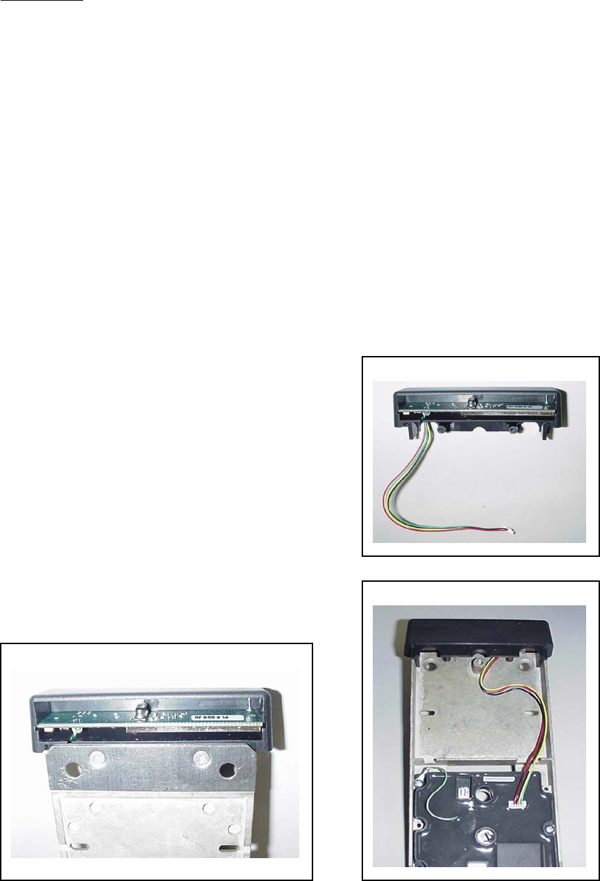
Figure 1
Introduction
The Messenger system is a hybrid solution to networking locks in a hospitality environment.
Each door lock has a low power, limited bandwidth, and short-range digital radio system.
The lock uses this Messenger radio to communicate use history and operating status to a
local wireless Messenger transceiver hub, which is capable of communicating with as many
as 64 individual door locks. The transceiver hubs are all connected to a host PC via a wired
or wireless Ethernet network. The host PC acts as a server for both the Saflok Windows
6000 operating system and the Saflok Messenger database.
Communication between the Messenger database and the locks is two-way; either the host or
lock initiates messages. Messages originating at the lock are transmitted directly to the
transceiver hub, which is continuously powered and predominantly in the receive mode.
The transceiver hub then acts as a gateway device, decoding the wireless message from the
lock and transferring it to the Ethernet infrastructure. Messages originating at the host are
sent to the transceiver hub via the Ethernet and stored in a memory buffer. The lock wakes
up periodically and checks the transceiver hub for stored messages, and then returns to
“sleep,” enabling long life from the primary batteries operating the Saflok.
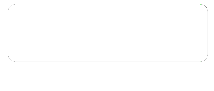
The radio device is installed in the upper
plastic end cap of the inside trim (See
Figure 1 and 2.) and connects to the locks
PCB with a four-wire harness that
provides both power and serial
communications. (See Figure 3.) When
the lock is produced at the factory, the
radio is plugged in, tested, and then turned
off to conserve battery power during
transit and construction. The radios shall
be left in the off position until the door
lock and network infrastructure
installations are complete.
Figure 2
Figure 3

Site Design
Transceiver hub locations are the most critical element of establishing a reliable and cost
effective wireless Messenger network. An insufficient quantity of hubs or incorrectly
positioned hubs may result in failed connections, while an overabundance of hubs creates
excessive Ethernet drops and installation costs.
The Messenger wireless devices are capable of indoor ranges in excess of a 40 meter radius.
However, building architecture and construction materials employed will dramatically
influence the locations of the transceiver hubs. Flooring plays an especially significant role;
steel decking will result on transceiver hubs being located on every floor while other
construction techniques will reduce the number of required transceiver hubs to every second
or third floor. Actual on-site range studies shall be performed in determining the actual hub
locations. Consult with your local Saflok representative on scheduling a site survey.
System Protocol / FCC Requirements
In the United States, the Messenger system uses a license-free shared-space radio frequency
bandwidth between 902MHz and 928MHz. The Saflok Messenger devices employ at least
50 different frequencies and “frequency hop” to avoid jamming and collisions in this “shared
space.” All Saflok Messenger equipped units will have the following label. Do not remove
the label from the enclosures that it is attached to.
Changes or modifications not expressly approved by Computerized Security
Systems, Inc. could void the user's authority to operate the equipment.
This product needs to be kept 20cm from the body due to RF exposure.
©2004 Pat pend Computerized Security Systems, Inc.
Contains Transmitter Module FCC ID: SAPMESSENGER
This device complies with Part 15 of the FCC Rules. Operation is
subject to the following conditions: (1) this device may not cause
harmful interference, and (2) this device must accept any interference
received, including interference that may cause undesired operation.
The transmitter module in each device shall have the following label. Use only products that
bear this label and do not remove the label from the modules that it is attached to. Do not
modify modules or attempt to service the module at any time. Part replacements shall only
be done through Computerized Security Systems, Inc.
Transmitter Module FCC ID: SAPMESSENGER
This device complies with Part 15 of the FCC Rules. Operation is
subject to the following conditions: (1) this device may not cause
harmful interference, and (2) this device must accept any interference
received, including interference that may cause undesired operation.
©2004 Pat pend Computerized Security Systems, Inc.
Installation
Attach the Saflok door locks to the doors and test for normal operation with an opening key.
(Refer to the Saflok MT Lock Installation and Programming Guide.)
Install the Messenger transceiver hubs in the locations identified by the site survey floor plan.
Each hub location will have a static IP address. Record the IP address for each hub on the
floor plan in the appropriate location representing that hub’s location.
Connect the Messenger transceiver hubs to the Ethernet network and then to power, using the
power supply provided. (See Figure 4)
Verify that all installed transceiver hubs are properly connected via Ethernet to the host
computer by running the utility “Find Hub” from the Messenger host PC. (Refer to the
Saflok Messenger Database Function Manual.)
Turn on the lock radios by inserting and removing the “Radio On” key into each lock. The
door locks will then automatically associate with a close proximity transceiver hub. If more
than one hub is within range, the door lock radio will associate with the first transceiver hub
that responds, even if it is not the closest hub. Once the lock associates with the transceiver
hub, the transceiver hub will use the Ethernet to notify the server that it is the controlling hub
for that lock, and all messages initiated by the host will pass through the appropriate
transceiver hub to get to the intended lock.
Operate the locks with a master key. The use of the master key will appear on the server’s
screen within a short period of time, verifying the locks connection to the server.
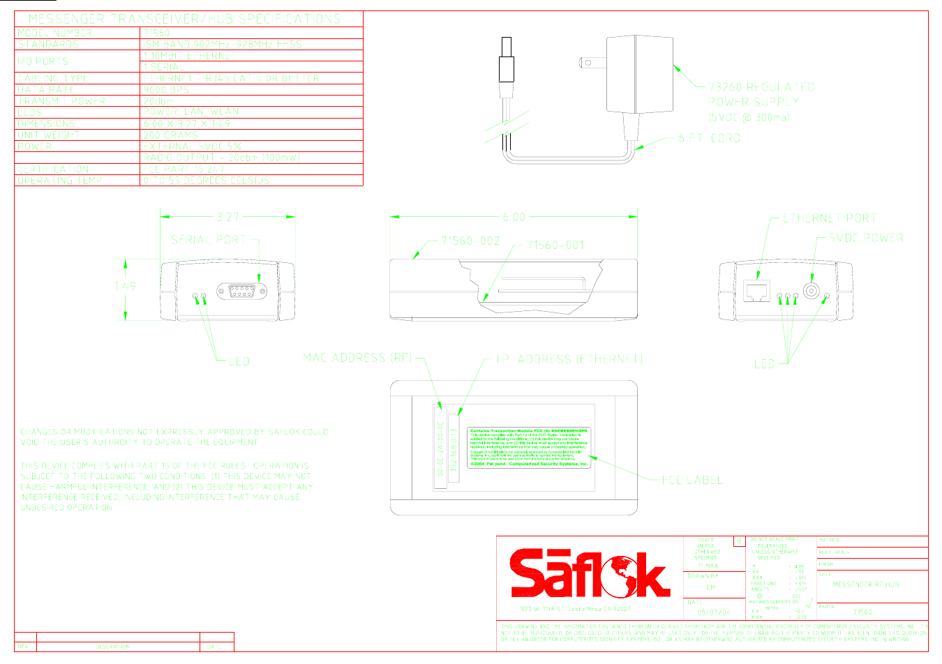
Figure 4