dormakaba EAD E3200 RFID Reader User Manual TM T9700V2 201705 en
Kaba GmbH RFID Reader TM T9700V2 201705 en
User Manual
Terminal 97 00
04043552 - 05/2017
DRAFT
EN
Technical Manual
dormakaba EAD GmbH
Albertistraße 3
78056 Villingen-Schwenningen
Germany
T: +49 7720 603-0
www.dormakaba.com
Company headquarters: Heiligenhaus
Copyright © dormakaba 2017
All rights reserved.
No part of this document may be reproduced or used in any form or by any means without prior written permis-
sion of dormakaba Schweiz AG.
All names and logos of third-party products and services are the property of their respective owners.
Subject to technical changes.
04043552 - 05/2017 DRAFT
Table of ContentsTechnical Manual
304043552 - 05/2017 Terminal 97 00DRAFT
Table of Contents
1 About this document 7
1.1 Validity 7
1.2 Target group 7
1.3 Content and purpose 7
1.4 Using the document 8
1.5 Additional documentation 8
1.6 Warnings 9
1.6.1 Hazard categories 9
1.6.2 Symbols 9
1.7 Information 9
1.8 Instructions 10
2 Basic safety information 11
2.1 Proper use 11
2.2 Assembly and installation 11
2.3 Service and maintenance 11
2.4 Accessories and spare parts 11
2.5 Electrical hazards 12
2.6 Handling of lithium batteries 12
2.7 ESD protective measures 13
2.8 Environmental protection 13
3 Product description 14
3.1 Overview 14
3.2 Technical data 15
3.2.1 System 15
3.2.2 Multimedia 15
3.2.3 Interfaces/Communication 16
3.2.4 Reader 16
3.2.5 Inputs/Outputs 16
3.2.6 Power supply 17
3.2.7 Uninterruptible power supply 17
3.2.8 Ambient conditions 17
3.2.9 Dimensions 18
3.3 Conformity 21
3.4 Marking 22
4 Construction and function 23
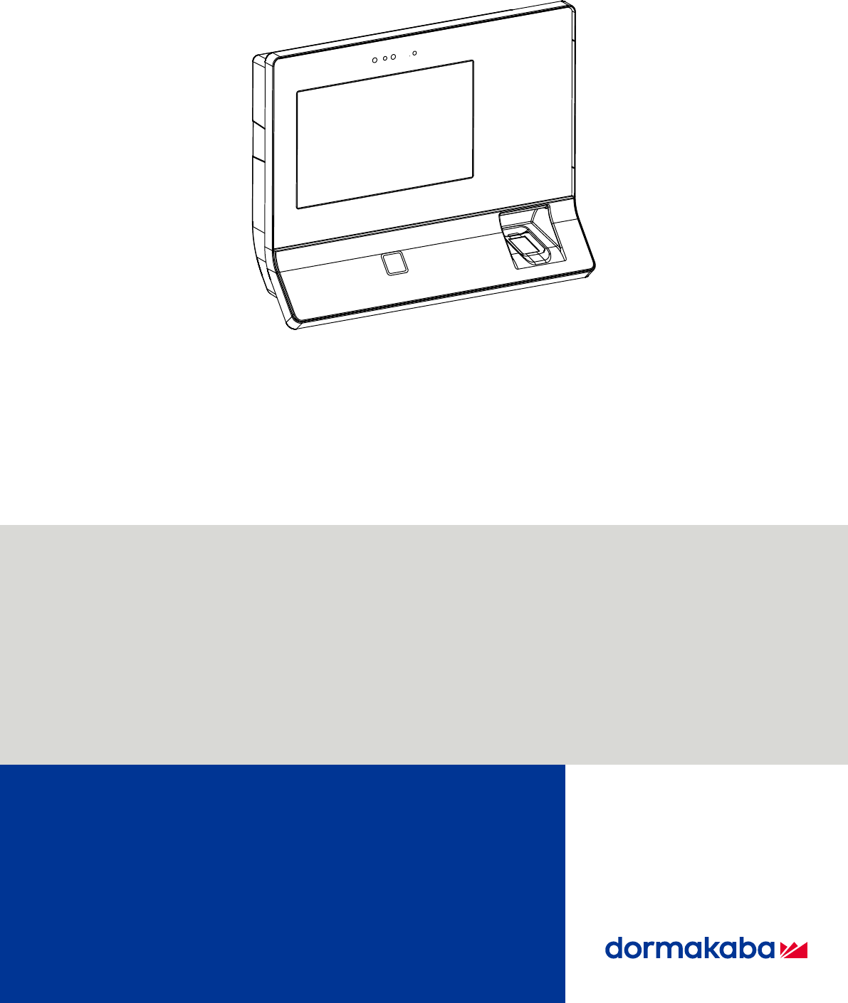
4.1 Device structure 23
4.1.1 Terminal housing - Front 24
4.1.2 Terminal housing - Rear side 25
4.1.3 Docking station 26
4.1.4 Interface assignment 30
4.1.5 Uninterruptible power supply UPS510 30
4.2 Product versions 31
4.2.1 Basic equipment 31
4.2.2 Optional equipment (not retrofittable) 31
4.2.3 Optional equipment (retrofittable) 31
4.2.4 Accessories 31
4.3 Terminal software 32
4.3.1 BaseApp 32
4.3.2 Kaba test program 32
4.3.3 B-Client HR30 terminal software 32
4.3.4 B-Client HR30 software options 32
4.4 System connection 35
4.4.1 Communication principle 35
Table of Contents Technical Manual
4 04043552 - 05/2017Terminal 97 00 DRAFT
4.4.2 Parametrization 35
4.4.3 Authorizations 35
4.4.4 Data from the terminal 35
4.4.5 Operating states 36
4.4.6 Devices with biometric reader 36
4.5 Authentication types 37
4.5.1 Mode 1: Identification 37
4.5.2 Mode 2: Verification 37
4.5.3 Mode 3: Verification (ID) 37
4.5.4 Mode 4: Combination of modes 1 and 2 37
4.5.5 Mode 5: Combination of modes 2 and 3 37
4.5.6 Alternative types of authentication 38
4.5.7 Additional PIN entry 38
4.6 CardLink 39
5 Installation 40
5.1 Installation conditions 40
5.1.1 General 40
5.1.2 Installation site 40
5.1.3 Connections 40
5.1.4 Power supply 41
5.1.5 Cable entry 42
5.2 Installation lines 43
5.2.1 24 V DC power supply 43
5.2.2 Mains voltage supply 43
5.2.3 Ethernet 43
5.2.4 Inputs/Outputs 43
5.3 Fastening the docking station 44
5.4 Connections 45
5.4.1 Connecting the network cable 45
5.4.2 Connecting the mains voltage 45
5.4.3 Mains fuses 46
5.4.4 Connecting 24 V DC power supply 47
5.4.5 Digital inputs 48
5.4.6 Relay outputs 49
5.4.7 Connecting an external reader 50
5.5 Uninterruptible power supply UPS510 51
5.6 Fasten the terminal housing to the docking station. 52
6 Commissioning 53
6.1 Network requirements 53
6.1.1 Communication 53
6.1.2 Comparing finger templates 53
6.1.3 Automatic registration via B-COMM 53
6.2 Automatic registration via B-COMM 54
6.2.1 Cancelling automatic registration 54
6.3 Manual settings 55
6.4 Settings via the Kaba test program 56
6.4.1 Service language 56
6.4.2 Reader settings 56
6.5 Service Interface 59
6.5.1 Remote access 59
6.5.2 Accessing the service interface locally from the B-Client HR30
terminal software. 60
6.5.3 Accessing the service interface locally from the BaseApp 61
6.6 Android system settings 62
6.6.1 Network settings 63
6.6.2 Settings for adjustment to the environment 66
6.7 Reader initialization 67
6.7.1 LEGIC 67
6.7.2 MIFARE (ARIOS) 68
6.7.3 MIFARE (Baltech) 68
6.8 SFTP server 69
Table of ContentsTechnical Manual
504043552 - 05/2017 Terminal 97 00DRAFT
6.8.1 Preconditions 69
6.8.2 Establishing an SFTP connection 69
6.8.3 Information on the key file 70
6.8.4 Important directories and files 71
6.9 Remote setup 72
7 Operation 73
7.1 Operating elements 73
7.2 Display 73
7.3 Touch screen 73
7.4 Navigation keys 74
7.5 RFID reader 75
7.6 Biometric reader 75
7.7 Swipe reader 76
7.8 Symbols for user guidance 77
7.8.1 Function keys 77
7.8.2 Input prompt 78
7.8.3 Error states 79
7.8.4 CardLink 79
7.8.5 Finger entry 80
7.9 BaseApp 81
7.9.1 Starting the application 81
7.9.2 App management 82
7.9.3 System Information 84
7.10 B-Client HR30 terminal software 85
7.10.1 Starting the terminal software 85
7.10.2 Shutting down the terminal software 86
7.10.3 Info functions 87
7.10.4 Registering new fingerprints at the terminal 88
8 Maintenance 92
8.1 Backup battery 92
8.1.1 Battery change 92
8.2 Replacement of the uninterruptible power supply UPS510 93
8.3 Cleaning the housing 93
8.4 Installation/Update of the terminal software 94
8.4.1 Data backup 94
8.4.2 Preparing installation/update 94
8.4.3 Performing an update 94
8.4.4 Performing the installation 95
8.5 Android update 95
9 Packaging/Returns 96
9.1 Complete devices 96
9.2 Electronic components 96
9.3 Labelling 97
10 Disposal 98
Index 100
Table of ContentsTechnical Manual
604043552 - 05/2017 Terminal 97 00DRAFT
About this documentTechnical Manual
704043552 - 05/2017 Terminal 97 00DRAFT
1 About this document
1.1 Validity
This document describes the product:
Product designation: Terminal 97 00
Product ID: 9700-K6
Item number 04079701
Terminal software: 735-05-X-K02 - B-Client HR30
BaseApp: 771-05-X-K02
Kaba test program 797-05-X-K02
Date of manufacture: From April 2017
This document describes all product versions and all optional features and functions. Options
are subject to a charge and therefore only available if purchased. Additional features and
functions may not be available at the time the document is issued and may only be available
for purchase at a later date.
1.2 Target group
This quick start guide is intended for skilled persons only.
The descriptions are intended for skilled persons trained by the manufacturer. The descrip-
tions are no replacement for product training.
For reasons of equipment safety, the installation, maintenance and service measures de-
scribed in this documentation should only be carried out by skilled persons in accordance with
EN 62368-1 (Audio/Video, Information and Communication Technology Equipment – Part 1:
Safety Requirements).
Skilled person is the designation for people who have the appropriate technical training and
experience in setting up the equipment. Skilled persons are expected to use their training and
experience to identify any risks to themselves and others that may arise while carrying out
these activities, and to minimise these risks as far as possible. It is the skilled person’s re-
sponsibility to ensure that the conditions stated by the manufacturer and the applicable regu-
lations and standards are complied with when carrying out these actions.
This documentation is also used to provide information for persons with the following tasks:
• Project planning and implementation
• Putting the product into operation within a network
• Connecting the product to the user software by programming customer applications
• Customer-specific adjustment through parameter setting on the product
1.3 Content and purpose
Content is limited to the assembly, installation, commissioning and basic operation of the
product.

About this document Technical Manual
8 04043552 - 05/2017Terminal 97 00 DRAFT
1.4 Using the document
To make it easier to find specific topics, please refer to the following document guidelines:
• The contents list at the start of the document provides an overview of all topics.
• The headings also list the relevant main chapter.
• Cross-references provide the number of the chapter in which more information can be
found. Example [ 5.7].
• There is an alphabetical index at the end of the document.
1.5 Additional documentation
Specific parametrization of the terminal software:
• B-Client HR30 reference manual
Web interface for commissioning:
• Service interface reference manual
Kaba ARIOS security concept and required system adjustments for different MIFARE media:
• Kaba MIFARE adjustments reference manual
Supplementary documentation is available on the Kaba website. Technical manuals can be
found in a secured area of the website.
• Access is only granted after a valid login.
• An account must be set up before logging in for the first time.
Opening login screen:
1. Open your internet browser and go to http://www.kaba.com.
2. Choose your language in the top right-hand corner of the screen.
3. Under 'Products', choose either the 'Access Management' or 'Workforce Management'
product division.
4. In the top right-hand corner of the screen, click on the following symbol:
5. Enter your email address and password to log in or create a new account (see below).
ðThe technical manuals can be found under 'Downloads'.
Creating an account:
1. Click 'Create account'.
2. Fill in the data fields and confirm your entries.
ðA confirmation link will be sent to your email address.
3. Click on the confirmation link in your email to activate your account.
About this documentTechnical Manual
904043552 - 05/2017 Terminal 97 00DRAFT
1.6 Warnings
Warnings with information, instructions and forbidden actions to prevent personal injury and
material damage are highlighted.
Please note the warnings! These are intended to help avoid accidents and prevent damage.
1.6.1 Hazard categories
Warnings are divided into the following categories:
DANGER
High risk
Designates an imminent danger resulting in serious injuries or death.
WARNING
Medium risk
Designates a potentially dangerous situation which can result in serious injuries or death.
CAUTION
Low risk
Indicates a potentially dangerous situation that can lead to minor injury.
NOTICE
Important information about the correct use of the product.
Non-adherence to the notes can lead to malfunctions. The product or something in its vicinity
could be damaged.
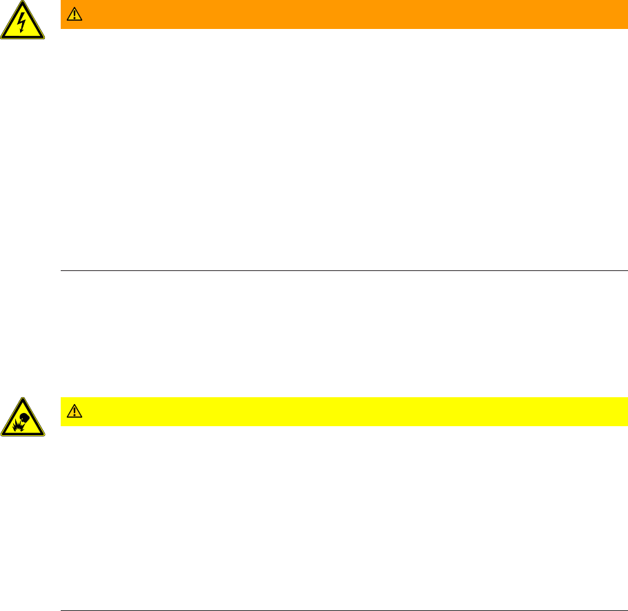
1.6.2 Symbols
Depending on the hazard source, the following symbols are used for warnings.
General hazard Hazard caused by electric power
Risk of explosion Risk to electronic components
caused by electrostatic discharge
1.7 Information
Information is designated by an info symbol.
Tips for usage, useful information.
These help to make the best use of the product and its functions.
About this document Technical Manual
10 04043552 - 05/2017Terminal 97 00 DRAFT
1.8 Instructions
Structure and symbols of the instructions are illustrated in the following example:
üPrerequisite
1. Step 1
ðInterim result
2. Step 2
ðResult

Basic safety informationTechnical Manual
1104043552 - 05/2017 Terminal 97 00DRAFT
2 Basic safety information
This product has been built according to the latest technology and accepted safety regula-
tions. Nevertheless, handling this product can pose a risk to people and property.
Read and observe the following safety information before using the product.
2.1 Proper use
This product has been designed exclusively for use as set out in the chapter Product Descrip-
tion. Any other use will be deemed improper use. The manufacturer accepts no liability for any
resulting damage. The user/operator bears sole responsibility for the risk.
2.2 Assembly and installation
Check the device for visible damage caused by transport or wrong storage. Do not start up
any damaged device!
Assembly and installation of the product may only be done by skilled personnel (see chapter 1
Target group).
Mains voltage installations may only be carried out by a certified specialized company or au-
thorized electricians.
The product should only be installed in locations which fulfil the environmental and technical
conditions specified by the manufacturer.
The manufacturer is not liable for damage arising due to improper handling or incorrect in-
stallation.
2.3 Service and maintenance
Conversions and modifications to the product may only be done skilled personnel (see chapter
1 Target group). Any conversions and modifications performed by other persons will exempt
us from any liability.
The elimination of faults and maintenance work may only be performed by skilled personnel
(see chapter 1 Target group).
2.4 Accessories and spare parts
Accessories and spare parts must comply with the technical requirements of the manufac-
turer. This is guaranteed with dormakaba original accessories and spare parts.
Basic safety information Technical Manual
12 04043552 - 05/2017Terminal 97 00 DRAFT
2.5 Electrical hazards
Installations involving the mains power may only be executed by approved specialist compan-
ies or authorized skilled electricians.
WARNING
Live connections at the docking station in devices equipped with integrated power supply unit
(BEX120 motherboard)
Carelessness can result in an electric shock.
üThe terminal housing may only be removed from the docking station by skilled personnel.
• Before removing the terminal housing from the docking station, the device must be de-en-
ergized.
• For permanently connected devices, the voltage must be switched off.
• For devices supplied by a separable connection, the mains plug must be pulled.
• Secure against being switched on again.
• Check for absence of voltage.
2.6 Handling of lithium batteries
To back up the real-time clock RTC, the device is equipped with a lithium manganese dioxide
battery type CR2032.
The battery is located on the rear side of the terminal housing.
CAUTION
Lithium batteries can explode or burst explosively.
Improper handling of lithium batteries may result in fires and explosions.
• Replace lithium batteries only with batteries of the same type.
• Do not open, drill through or squash lithium batteries.
• Do not burn lithium batteries or expose them to high temperatures.
• Do not short-circuit lithium batteries.
• Do not recharge lithium batteries.

Basic safety informationTechnical Manual
1304043552 - 05/2017 Terminal 97 00DRAFT
2.7 ESD protective measures
NOTICE
Danger of damage to electronic components from electrostatic discharge.
If electronic printed circuit boards and components are handled incorrectly, damage may oc-
cur which leads to their complete breakdown or sporadic faults.
• When installing and repairing the product, the general ESD protective measures are to be
observed.
• When handling electronic components, wear the ESD wrist strap. Connect the end of the
strap to an ESD socket or an unpainted, earthed metal component. This will safely and ef-
fectively conduct charges away from your body.
• Only handle the edges of printed circuit boards. Do not touch printed circuit boards or
connecting plugs.
• Put removed components on an anti-static surface or in an anti-static shielding container.
• Avoid contact between printed circuit boards and clothing. The wrist strap only protects
the printed circuit boards from static electricity on the body. Damage can still occur due
to static electricity on clothing.
• Only transport and ship removed modules in ESD-shielding, conductive protective con-
tainers.
2.8 Environmental protection
It is prohibited to dispose of the device in your domestic waste.
Used devices contain valuable materials that should be recycled. Properly dispose of used
devices.
Dispose of consumed batteries in accordance with state and local regulations.
Carefully store the batteries to be disposed of to avoid short circuits, crushing or destruction
of the battery casing.
Product description Technical Manual
14 04043552 - 05/2017Terminal 97 00 DRAFT
3 Product description
3.1 Overview
The terminal 97 00 can be used for time and attendance and for providing customer-specific
information and applications.
The operating system used of the terminal 97 00 is 'Android’. This allows applications, so-
called apps, to be used flexibly at the terminal. The system can be expanded at any time to
make it suitable for a wide range of tasks or also be supplemented by apps specifically de-
veloped for customer requirements.
For time and attendance, the B-Client HR30 terminal software is available. This terminal
software makes the device compatible in terms of data records with its predecessor series B-
web and B-net, allowing it to be connected to the host system via UDP using the communica-
tion software B-COMM. Connecting it to HTTP/HTTPS-based applications, such as b-comm
ERP5, b+ or EACM, is also possible.
To display information, the terminal is equipped with a 7' colour display with a resolution of
800 x 480 pixels.
The device is equipped with a touch screen operated by touching the glass front.
The time data is recorded by a RFID proximity reader and/or a biometric CBM reader (de-
pending on design)
A proximity sensor activates the device in the sleep or standby mode.
The terminal is equipped with an integrated microphone and an integrated loudspeaker and,
optionally, with a camera system.
Communication takes place via Ethernet. Alternatively and optionally, communication can
also take place via UMTS or WLAN.
Optionally, 2 outputs (relays) and 4 digital inputs are available for control functions.
Product descriptionTechnical Manual
1504043552 - 05/2017 Terminal 97 00DRAFT
3.2 Technical data
3.2.1 System
Operating system
• Android version 5.0.2 (Lollipop)
CPU
• BECO620 single-board CPU unit
Memory
• 2 GByte DDR3 RAM
• 8 GByte eMMC Flash
• Card slot for microSD or microSDHC card
Parameters and data records are retained without supply voltage.
RTC
The device has an integrated real-time clock. The function of the RTC is ensured for about 2
years by a lithium battery type CR2032 (on the rear side of the device) even without power
supply of the device.
Display
• TFT LCD display module
• Size: 17.8 cm (7.0”)
• Resolution: 800 x 480 pixels (16:9/WVGA)
• Colour depth: 24-bit (true colour)
• Backlit with white LED
Touch screen
• 7” PCAP touch screen over the complete display
• 10-finger multitouch support
• Resolution: 30 x 18 (x/y)
• Optional splinter protection
Biometric proximity sensor
• Optic proximity sensor for activating the biometric reader (option)
• Range 10-50 mm, sensitivity adjustable in 3 steps, can be switched off
Terminal proximity sensor
• Activates the device from the sleep or standby mode when approaching it within approx.
0.5 m
3.2.2 Multimedia
Camera (option)
• Integrated ¼ inch camera; resolution 5 megapixels
Audio
• Integrated microphone
• Integrated loudspeaker with power amplifier (3 W)
• 3.5 mm line-out jack
Product description Technical Manual
16 04043552 - 05/2017Terminal 97 00 DRAFT
3.2.3 Interfaces/Communication
Ethernet interface
• IEEE802.3 compatible10BASE-T/100BASE-TX /1000BASE-T Auto sensing, Auto MDIX
• IEEE802.1x security concept, EAP type MD5
WLAN (option)
• Mini PCIe WLAN adapter conforming to IEEE802.11 b/g/n (2.4 GHz)
• Encryption: WPA-PSK, WPA2-PSK and WEP security
Mobile radio (option)
• Mini PCIe HSPE module
• UMTS/HSPA: 850/900/1900/2100MHz
• GSM/GPRS/EDGE: 850/900/1800/1900 MHz
Serial interface RS-232 (option)
• Baud rates: 9600/19200/38400/57600/115200
• Hardware handshake (RTS/CTS)
USB
• 1 x USB 2.0 (host); 5 V/500 mA;
for example for connecting an external reader
3.2.4 Reader
Depending on model, the device supports the following readers:
RFID reader
• MRD - LEGIC prime/advant, MIFARE Classic/DESFire
• HID - iCLASS SE, iCLASS, Prox, Prox II
• HITAG - EM4102, HITAG1, HITAG2
Biometric fingerprint reader
• Biometric module (CBM) with integrated database for fingerprints.
• Optionally as CBM-E with extended approvals (PIV-IQS with FBI certification and FIPS
201 approved template evaluation)
• Depending on model, the reader has a storage capacity for 500, 3000 or 5000 persons (2
fingers per person)
Swipe reader in substructure housing
• Magnetic stripe tracks 1, 2, 3
• Red light barcode
• Infrared barcode
3.2.5 Inputs/Outputs
2 relay outputs (option)
• One potential-free switchover contact each
• Contact loading capacity: 30 V AC/DC; max. 2 A
4 digital inputs (option)
• Galvanically isolated from system
• Input voltage: max. 30 V DC, min. -30 V DC

Product descriptionTechnical Manual
1704043552 - 05/2017 Terminal 97 00DRAFT
3.2.6 Power supply
For the power supply of the device, the following alternatives are possible:
• PoE (Power over Ethernet)
• Mains power input (docking station with BEX120 motherboard required)
• 24 V DC power supply (docking station with BEX121 motherboard required)
PoE (Power over Ethernet)
Power supply of the terminal via the 8-wire Ethernet cable (max. 100 m)
• In accordance with IEEE802.3at/type 1 class 0 (0,44-12,95 W)
• Supported feed processes: Spare pair feed and phantom feed
Mains voltage input
• Voltage range: 100–240 V AC
• Frequency: 50/60 Hz
• Current consumption: max. 200 mA
24 V DC power supply
• Voltage range: 22–30 V DC
• Current consumption: max. 1 A
Only power supply units that fulfil the following requirements may be used for power supply:
LPS (Limited Power Source) and SELV (Safety Extra Low Voltage) in accordance with IEC/
EN/UL/CSA 60950-1 or ES1 and PS2 in accordance with IEC/EN/UL/CSA 62368-1.
3.2.7 Uninterruptible power supply
UPS510 (option)
The UPS510 consists of an electronic part with charging circuit and a rechargeable battery.
The components are housed in a self-contained housing. Uninterruptible operation of the
device in case of power supply failure is ensured by an NiMH battery with a capacity of 2100
mAh. The battery is fully charged after a charging time of 10 hours.
The UPS510 ensures operation in case of power supply failure for up to 30 minutes or approx.
200 bookings, whatever occurs first.
Condition: New battery, 100% charged, temperature 20 ° - 25 °C.
3.2.8 Ambient conditions
Ingress protection according to IEC 60529
• IP20 (devices with swipe reader)
• IP40 (devices with RFID and CBM readers)
Prerequisite: Cable entry from below using the enclosed grommets
Relative humidity
• 5% - 85%, non-condensing
Ambient temperature
• -5 °C – +45 °C (operation without UPS)
• 0 °C – +40 °C (operation with UPS)
• -25 °C – +70 °C (storage without UPS)
• -20 °C – +45 °C (storage with UPS)
Product description Technical Manual
18 04043552 - 05/2017Terminal 97 00 DRAFT
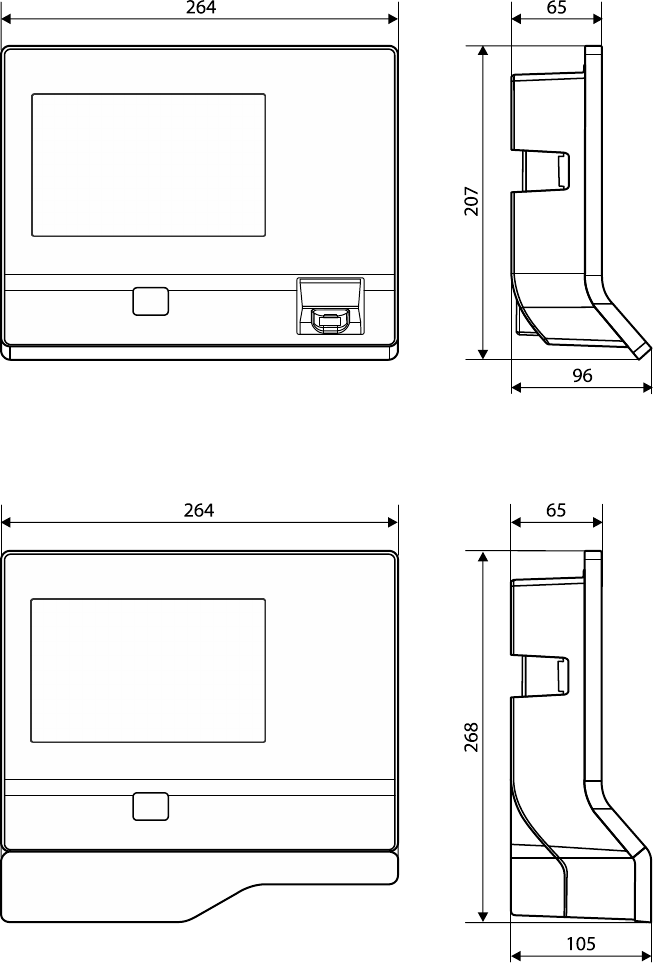
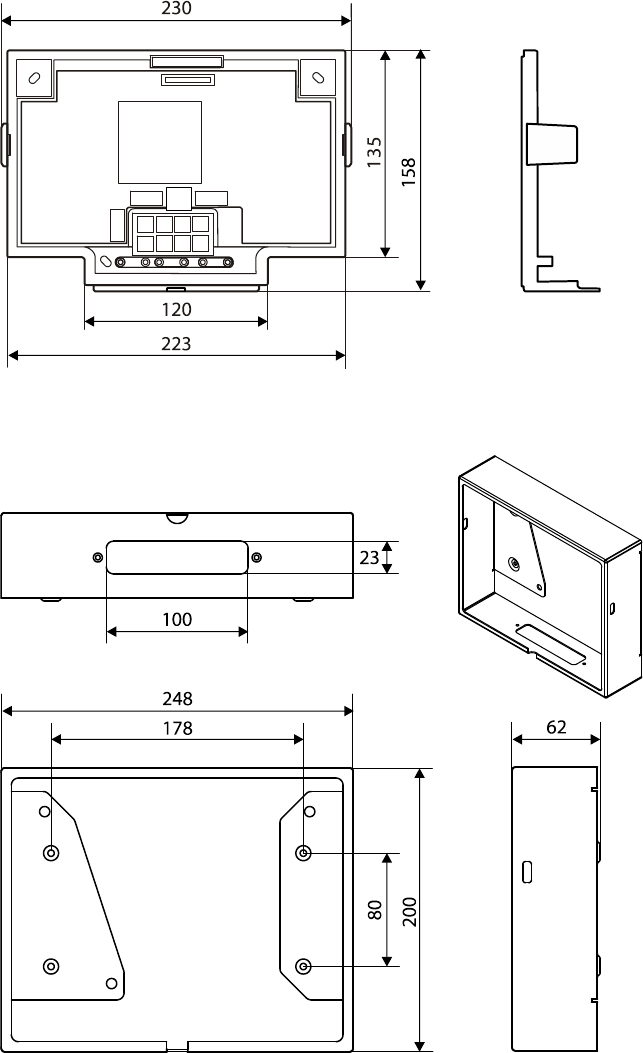
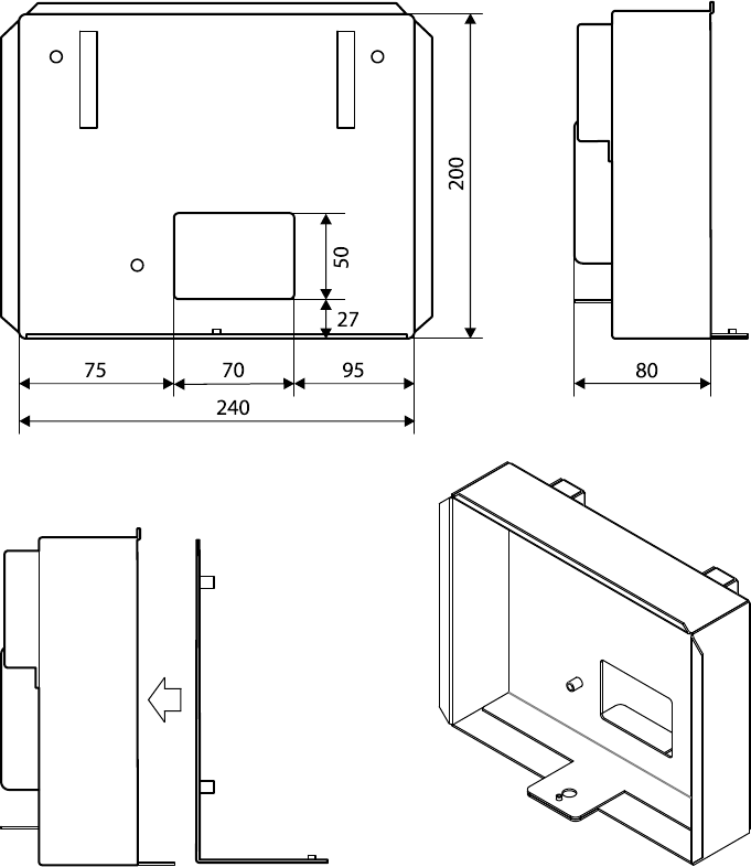
3.2.9 Dimensions
all dimensions are given in mm.
3.2.9.1 Terminal housing
3.2.9.2 Terminal with substructure housing
Product descriptionTechnical Manual
1904043552 - 05/2017 Terminal 97 00DRAFT
3.2.9.3 Docking station
3.2.9.4 Surface-mounted protective metal housing (accessories)
Product description Technical Manual
20 04043552 - 05/2017Terminal 97 00 DRAFT
3.2.9.5 Flush-mounted housing (accessories)

Product descriptionTechnical Manual
2104043552 - 05/2017 Terminal 97 00DRAFT
3.3 Conformity
This product conforms to the following standards:
EN 62368-1:2014
EN 55032:2015
EN 55024+A1:2015
according to the provisions of the EU directives
2014/35/EU - Low Voltage Directive (LVD)
2014/30/EU - Electromagnetic Compatibility (EMC)
The RFID readers MRD (LEGIC & MIFARE) and HID iCLASS SE / Prox used in this product
comply with the following standards
EN 300330-2 V1.6.1
EN 301489-3 V1.6.1
according to the provisions of the EU directive
2014/53/EU - Radio Equipment Directive (RED)
RoHS This device complies with the regulations of the Directive 2011/65/EU of the European Parlia-
ment and of the Council of June 8, 2011, on the restriction of the use of certain hazardous
substances in electrical and electronic equipment.
The original conformity declaration can be downloaded in PDF format from www.kaba.com/
conformity.
In addition, the product also complies with the following standards
UL60950-1:2007/R:2014-10
CAN/CSA-22.2 No. 60950-1:2007/A2:2014-10
UL62368-1:2014-12
CAN/CSA-22.2 No. 62368-1:2014-12
FCC Code of Federal Regulations,
CFR 47, Part 15,
Sections 15.107 and 15.109 (Class B)
IC Industry Canada Radio Standards Specifications
ICES-003 Issue 5, Sections 5(a)(i) and 5(b)(i) Class B (ITE)
The RFID readers MRD (LEGIC & MIFARE) and HID iCLASS SE / Prox used in this product
comply with the following standards
FCC Code of Federal Regulations,
CFR 47, Part 15, Sections 15.207, 15.209, 15.215 and 15.225
IC Industry Canada Radio Standards Specifications
RSS-GEN Issue 4, Sections 8.8, 8.9, 8.10 and
RSS-210 Issue 8, Section A2.6 (Category I Equipment)
Product description Technical Manual
22 04043552 - 05/2017Terminal 97 00 DRAFT
3.4 Marking
The rating plate is located on the underside of the device.
Information given on the rating plate:
• Designation of the device
• Item number
• Serial number
• Date of manufacture
• Connection data (supply voltage)
• CE marking
• WEEE marking according to DIN EN 50419
Construction and functionTechnical Manual
2304043552 - 05/2017 Terminal 97 00DRAFT
4 Construction and function
4.1 Device structure
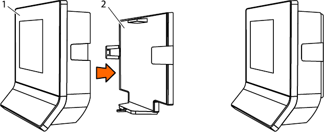
The device consists of the terminal housing (1) and the docking station (2).
The docking station is the wall mounting element of the device and, depending on the equip-
ment, the docking station contains additional electronics.
Construction and function Technical Manual
24 04043552 - 05/2017Terminal 97 00 DRAFT
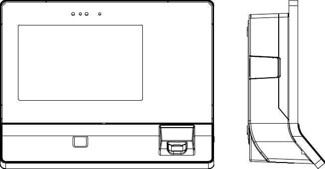
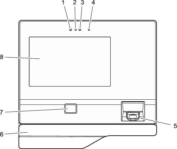
4.1.1 Terminal housing - Front
The terminal housing is the core device. The terminal housing essentially contains the CPU, the
TFT display with touch screen and up to two internal readers.
1 Integrated camera (option)
2 Camera flash (option)
3 Proximity sensor
4 Infrared LED for proximity sensor
5 Biometric reader (option)
6 Substructure housing with alternative RFID reader or swipe reader (option)
7 RFID reader (option)
8 TFT LCD display with PCAP touch screen
Construction and functionTechnical Manual
2504043552 - 05/2017 Terminal 97 00DRAFT
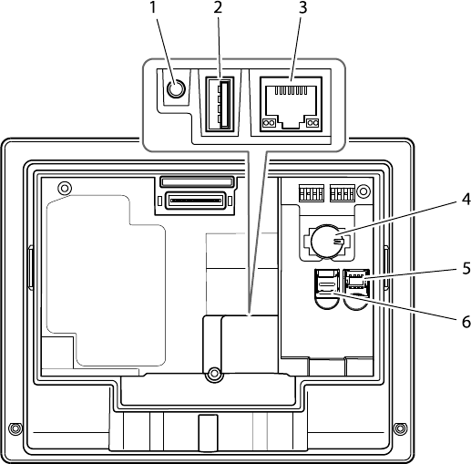
4.1.2 Terminal housing - Rear side
After removing the terminal housing from the docking station, the terminal rear side becomes
accessible.
The rear side of the terminal housing contains, among other things, the connection area and
card slots.
1 Audio line-out (3.5 mm jack)
2 USB port
3 Ethernet port (RJ45 socket)
4 CR2032 lithium battery for back-up of the RTC real-time clock
5 Card slot for a micro SIM card
6 Card slot for a microSD or microSDHC card
Construction and function Technical Manual
26 04043552 - 05/2017Terminal 97 00 DRAFT
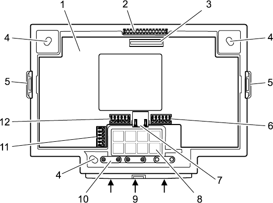
4.1.3 Docking station
The docking station is the wall mounting element of the device and is part of the standard
equipment. The docking station is fastened to the wall. The terminal housing is placed on the
docking station and secured.
The docking station has cut-outs for entry of the installation cables. The installation cables
can be entered from below and from the rear.
1 Motherboard (option)
2 Locking pin for the terminal housing
3 Motherboard/terminal housing contact
4 Long holes for wall mounting
5 Snap-in retaining tabs for the terminal housing
6 Connection terminal for the relay outputs
7 RJ45 connection for an external reader via RS-232
8 Cut-outs for cable entry from the rear
9 Cut-outs for cable entry from below
10 Cable clamps
11 Connection terminal for the additional interface (option)
12 Connection terminal for the inputs
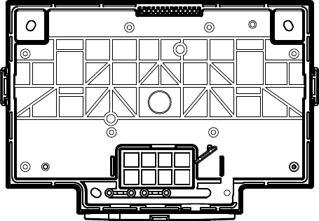
Construction and functionTechnical Manual
2704043552 - 05/2017 Terminal 97 00DRAFT
4.1.3.1 Docking station without motherboard
In its basic equipment, the docking station does not include any electronics. In this case, the
docking station serves as pure wall mounting element.
Communication takes place via the Ethernet network. The device is supplied with power via
PoE (Power over Ethernet). This is why only the network cable has to be connected to the ter-
minal housing.
The network cable can be introduced into the docking station from the rear or from below.

Construction and function Technical Manual
28 04043552 - 05/2017Terminal 97 00 DRAFT
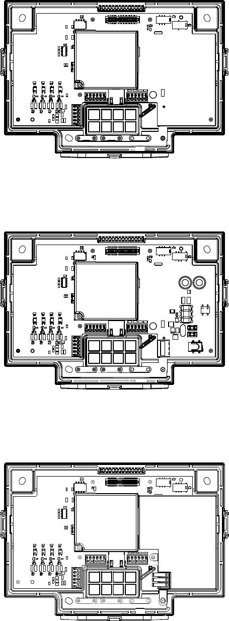
4.1.3.2 Docking station with motherboard
Optionally, the docking station is equipped with a motherboard.
The motherboard is available in 3 different versions. The differences refer to the design of the
power supply. Otherwise, the motherboards are identical.
• BEX122 motherboard - Power supply via PoE
• BEX121 motherboard - Power supply by 24 V DC
• BEX120 motherboard - Power supply by mains voltage
In general, the motherboard has the following hardware equipment:
RS-232C interface
The RS-232C interface can be used for connecting an external reader, for example a CCD bar-
code scanner.
It is connected to the RJ45 socket of the motherboard.
Additional interface
The motherboard has a slot for an optional interface module. The BEX301 - RS-232C interface
or BEX302 - RS-485 interface can be used.
The interface can be used for customized applications. The additional interface is without use
in the standard equipment.
The interface signals are connected via a 6-pin terminal on the motherboard.
Outputs
The motherboard has 2 relay outputs with changeover contacts. The relays can be used, for
example, for activating door openers or signal generators.
Inputs
The motherboard has 4 digital inputs. The inputs can be used for a door opener key, access
control or a customized application.
Sabotage contact
Devices whose docking station is equipped with a motherboard are provided with a sabotage
contact.
The sabotage contact is activated when the terminal housing is disconnected from the dock-
ing station plus motherboard.
This causes the device to generate an appropriate alarm record. Prerequisite: Device supplied
via PoE or via a UPS510. Not possible for devices supplied by the motherboard and not
equipped with a UPS, since after removal of the terminal housing from the docking station
the power supply is also disconnected.
Whether hardware options are supported, depends in part on the terminal software used and
the acquired software options!
Construction and functionTechnical Manual
2904043552 - 05/2017 Terminal 97 00DRAFT
4.1.3.3 Docking station with BEX122 motherboard
The BEX122 motherboard is used in devices whose power supply takes place via PoE. The
BEX122 motherboard is not equipped with an additional power supply unit nor with a power
supply input.
4.1.3.4 Docking station with BEX121 motherboard
For power supply of the device, the BEX121 motherboard has a 24 V DC input with over-
voltage protection and transient filter. This motherboard is used when the device is supplied
with 24 V DC.
4.1.3.5 Docking station with BEX120 motherboard
The BEX120 motherboard has a 100–240 V AC mains voltage input and an integrated limited
power source power supply unit (LPS). This motherboard is used when the device is supplied
with mains voltage.
Construction and function Technical Manual
30 04043552 - 05/2017Terminal 97 00 DRAFT
4.1.3.6 Overview of the equipment
Equipment/Motherboard none BEX120 BEX121 BEX122
Power supply
PoE X X
24 V DC X
Mains voltage X
Interfaces
RS-232C interface X X X
Additional interface X X X
Inputs/Outputs
2 relay outputs X X X
4 digital inputs X X X
4.1.4 Interface assignment
COM port Assignment
COM1 Internal reader (integrated into terminal housing)
COM2 Internal reader (integrated into terminal housing)
COM3 Additional interface (docking station motherboard)
COM4 RS-232 for external reader (docking station motherboard)
4.1.5 Uninterruptible power supply UPS510
The uninterruptible power supply UPS510 ensures operation in case of short-term power sup-
ply failure.
The UPS510 is snapped into place on the rear side of the terminal housing.
The UPS510 can be retrofitted or replaced at any time.
Construction and functionTechnical Manual
3104043552 - 05/2017 Terminal 97 00DRAFT
4.2 Product versions
4.2.1 Basic equipment
Terminal housing
• 7” WVGA display
• 7” touch screen
• Proximity sensor
• Ethernet 10/100/1000
• Power supply via PoE (Power over Ethernet)
Docking station
• Docking station as wall mounting element without electronics
4.2.2 Optional equipment (not retrofittable)
Multimedia
• Camera
Communication
• WLAN
• Mobile radio
Reader integrated into terminal housing
• RFID reader (MRD, HID, HITAG)
• Biometric fingerprint reader (CBM/CBM-E for 500, 3000 or 5000 persons)
Reader in additional substructure housing
• Magnetic card reader
• Barcode swipe reader
• Other RFID readers
4.2.3 Optional equipment (retrofittable)
Protection in case of power supply failure
• Uninterruptible power supply UPS510
Docking station with motherboard
BEX120, BEX121 and BEX122 motherboards:
• RS-232C interface for connecting an external reader
• Adapter for additional interface
• 2 relay outputs
• 4 digital inputs
BEX121 motherboard:
• Power supply input for external 24 V DC
BEX120 motherboard:
• Power supply connection for mains voltage
4.2.4 Accessories
• Elastic protective frame
• Surface-mounted protective metal housing
• Flush-mounted housing
Construction and function Technical Manual
32 04043552 - 05/2017Terminal 97 00 DRAFT
4.3 Terminal software
4.3.1 BaseApp
The BaseApp is the user interface of the android-based terminal. The BaseApp is part of the
basic equipment and forms the platform for all applications (apps) used on the terminal.
The BaseApp essentially performs the following functions:
• Protection of the operating system from unauthorized access (system isolation). Only
controlled access to the android operating system is possible.
• Organization and start-up of applications (apps).
• Provision of functions and interfaces for access to the hardware.
• Provision of service functions via a web interface (service interface) for commissioning
and maintenance of the device.
4.3.2 Kaba test program
The Kaba test program application (TP) has already been installed on the terminal ex works.
The test program app offers the following functions:
• Adjustment of various system settings locally to the device
• Retrieval of system information
• Testing of individual system components
4.3.3 B-Client HR30 terminal software
The B-Client HR30 terminal software allows the device to be used as time and attendance
terminal.
The B-Client HR30 terminal software makes the device compatible in terms of data records
with terminals of the B-web and B-net series, allowing it to be connected to the host system
via the communication software B-COMM.
4.3.4 B-Client HR30 software options
The usable range of functions of the device is given by the options activated in the 'sop.ini’ li-
cence file by means of the corresponding licence key.
Some software options require an appropriate hardware equipment.
Upon purchasing an additional software option later on, the existing licence file must be re-
placed with the new extended licence file.
The sop.ini is located in the following directory
/data/data/com.kaba.apps.hr/files/init.
From the parameters, you can determine which functions are active.
The relevant parameters are located in the [BClientHR30] section.
Each parameter has the value true or false.

Construction and functionTechnical Manual
3304043552 - 05/2017 Terminal 97 00DRAFT
4.3.4.1 Licence for the B-Client HR30 terminal software.
Entry in the licence file:
[BClientHR30]
BClientHR30Enabled=true
4.3.4.2 CardLink
Entry in the licence file:
CardLinkEnabled=true
Enables CardLink update and CardLink validation in connection with LEGIC or MIFARE read-
ers.
4.3.4.3 Data encryption
Entry in the licence file:
EncryptionEnabled=true
Data encryption via Ethernet UDP in connection with the communication software
B-COMM.
Data encryption via HTTPS with XML communication.
4.3.4.4 Door control
Entry in the licence file:
AccessControlEnabled=true
Hardware prerequisite: Docking station with motherboard
Enables:
• Use of 4 inputs for door surveillance and door opening.
• Use of 2 relay outputs for door opening or break signal control
• Check for time profiles:
• PIN check.
• Check for double access.
4.3.4.5 LocalEnrollment
Entry in the licence file:
LocalEnrollmentEnabled=true
Enables the registration of new fingerprints via the biometric reader locally at the terminal.
4.3.4.6 Memory options
Entry in the licence file (possible values: 0, 1, 2, 3, 4):
BufferConfiguration=
The following overview shows the maximum possible number of data records in the respective
memory option.
Record type/Option 0 1 2 3 4* 4
Master records 200 1,000 2,000 10,000 30,000 50,000
Registration records 10,000 10,000 10,000 10,000 30,000 50,000
Update records* 400 2,000 4,000 20,000 60,000 -
Validation records* 200 1,000 2,000 10,000 30,000 -
*in connection with CardLink
Construction and function Technical Manual
34 04043552 - 05/2017Terminal 97 00 DRAFT
4.3.4.7 Starting native apps
Entry in the licence file:
NativeAppEnabled=true
Enables the start of native apps from B-Client HR30.
4.3.4.8 Partner application
Entry in the licence file:
PartnerinterfaceEnabled=true
Supports partner applications. Partner application is called from
B-Client HR30 with data transfer.
4.3.4.9 Browser start
Entry in the licence file:
BrowserEnabled=true
Enables the browser to be started from B-Client HR30. Transferred data can be displayed or
web sites can be loaded.
4.3.4.10 Replacement terminal
Entry in the licence file:
ReplacementEnabled=true
Identifies a replacement terminal.
In connection with the communication software B-COMM, the terminal can be easily and
comfortably replaced with a device containing the same hardware when servicing is required.
The licence file of the replaced device is automatically adapted during commissioning and in-
stalled in the replacement terminal.
Construction and functionTechnical Manual
3504043552 - 05/2017 Terminal 97 00DRAFT
4.4 System connection
This chapter describes the principle of host host connection and applies exclusively to devices
with B-Client terminal software. For detailed descriptions, please refer to the reference
manual of the terminal software.
4.4.1 Communication principle
Communication between the terminal 97 00 and a superior host computer takes place via an
Ethernet network as standard.
Data exchange between the B-Client HR30 terminal software and the customer application
takes place via a communication software. The communication software transmits the data
records collected by the terminals to files or transmits them to the customer application via a
defined interface.
4.4.2 Parametrization
The varied functions of the terminal depend in particular on the set parameters. Parametriza-
tion allows extensive adaptation to a wide range of applications. During parametrization the
currently valid parameters are changed and stored in the memory of the terminal. The re-
quired parameters are provided by the customer application and transmitted to the terminal
in the form of parameter records.
4.4.3 Authorizations
Information relevant to authorizations are provided by the customer application in the form
of personnel master records.
All information relating to a certain badge number or group is stored in the master record.
The master record contains information on authorizations, time profiles, person-related dis-
play texts and the PIN number.
Master records can be stored in the terminal. This allows the terminal itself to decide whether
a booking is authorized. Whether a booking is authorized, can also be inquired by the host in
the 'online’ operating state. In this case, no master records are required in the terminal. Mas-
ter records can be transmitted to the terminal at any time, resulting in the current master re-
cord being overwritten. Individual master records can be deleted by the host. Likewise, master
records can be requested by the host.
The number of master records that can be loaded to the terminal depends on the device hard-
ware and on the licensed memory configuration.
4.4.4 Data from the terminal
After a booking, the terminal generates a registration record. The registration records con-
tains the information who has booked when at which terminal by pressing which function key.
At what time this registration record will be transmitted to the host computer, depends on
the operating state of the terminal.
Certain states and events result in the generation of alarm records and status records.
Construction and function Technical Manual
36 04043552 - 05/2017Terminal 97 00 DRAFT
4.4.5 Operating states
4.4.5.1 Online
After a booking, the terminal carries out the parametrized tests and enters the test result in
the registration data record as error detection. The registration data record is transmitted to
the host. Following this, the terminal expects a logical booking response from the host. Along
with it, the host communicates to the terminal the decision whether or not the booking is au-
thorized.
If the terminal does not receive a logical booking response from the host, it will switch to the
offline operating state and decide itself based on the parametrized tests whether the booking
is authorized. As soon as the host can be reached again, all data records saved in the mean-
time in offline will be transmitted to the host. Then the terminal automatically switches again
to the online operating state.
4.4.5.2 Offline
After a booking, the terminal carries out the parametrized tests and decides immediately
whether or not the booking was authorized by sending an internal booking response. Depend-
ing on the parametrization, registration records are stored in the terminal. As soon as the
host can be reached, all data records saved since the last transmission will be transmitted to
the host.
4.4.5.3 Autonomous
After a booking, the terminal carries out the parametrized tests and decides immediately
whether or not the booking was authorized by sending an internal booking response. Depend-
ing on the parametrization, registration records of authorized and unauthorized bookings are
stored in the terminal.
If the host can be reached, any error and alarm records that may be available will be trans-
mitted to the host.
The saved registration data records are transmitted to the host on request together with a
special data record.
4.4.6 Devices with biometric reader
Biometric software
When communicating via B-COMM, the program package B-COMM - Biometrics option is re-
quired for managing and distributing the finger templates.
Communication with the Finger Template Control Service (FTCS) of the biometrics software
takes place via Ethernet/UDP and a separate channel.
When connected to HTTP/HTTPS-based applications, the distribution of the finger templates
also takes place via the HTTP/HTTPS host channel.
Standalone mode
Alternatively, operation without a biometric host is also possible. In this ‘Standalone mode’, all
fingerprints of persons must be registered by the reader of the terminal. In this case, the fin-
ger templates are only saved in the reader’s internal database. If they get lost, all persons
have to be registered again at the terminal.
This is why the Standalone mode without biometric software is only recommended for very
small solutions (max. 20 persons).
Construction and functionTechnical Manual
3704043552 - 05/2017 Terminal 97 00DRAFT
4.5 Authentication types
Devices equipped with biometric reader can be operated in 5 authentication modes. Modes 2
to 5 require an additional RFID reader.
4.5.1 Mode 1: Identification
Mode 1 is the typical biometric identification
The biometric features of all persons authorized to book are registered by an enrollment sta-
tion and distributed to the individual readers.
During a booking the fingerprint of the person is registered. The biometric features are com-
pared to the data records If a matching reference data record is found, the person has been
identified. The associated ID is sent in the registration data record to the superior access con-
trol manager.
4.5.2 Mode 2: Verification
Mode 2 is a verification based on time profiles. The person's biometric data is stored on the
RFID badge, which is used for verification.
First, a person books using the RFID badge. The ID segment and the biometric segment are
read. The master record and biometric time profile check shows whether a biometric verifica-
tion is required.
If a verification is required, the biometric reader is activated. This is the request for the person
to put on the finger. The registered biometric features are now compared to the data saved in
the biometric segment. If the features of the fingerprint are identical, the booking is valid.
4.5.3 Mode 3: Verification (ID)
Mode 3 is a verification based on time profiles of two identification features. The ID of the
RFID badge is compared to the ID of biometric identification.
First, a person books using the RFID badge. The ID segment is read.
The master record and biometric time profile check shows whether an additional biometric
identification is carried out.
If a biometric identification is required, the biometric reader is activated. This is the request
for the person to put on the finger. The biometric features are compared to the data records
of the reader's internal database. If the matching reference data record is found, the two IDs
are compared. If the IDs are identical, the booking is valid.
4.5.4 Mode 4: Combination of modes 1 and 2
Mode 4 allows parallel use of biometric identification and biometric verification based on time
profiles. A maximum of 5000 persons can be authenticated per identification. If this capacity
is insufficient, further persons can be authenticated by verification.
4.5.5 Mode 5: Combination of modes 2 and 3
Mode 5 allows parallel use of verification based on time profiles and verification (ID). This al-
lows parallel operation of RFID badges with and without biometric segment.

Construction and function Technical Manual
38 04043552 - 05/2017Terminal 97 00 DRAFT
4.5.6 Alternative types of authentication
For people with less defined biometric characteristics an alternative way of authentication
can be enabled. This is made possible by storing a biometric identification in the personnel
master record, see reference manual of the terminal software.
The following options are possible instead of biometric identification:
• Entry of the ID on the keypad (only mode 1)
• Entry of the ID via the RFID badge
4.5.7 Additional PIN entry
A PIN entry via the keypad can be requested via the time profile for all types of authentication
(see reference manual of the B-Client terminal software).
In order to increase security, an additional PIN should be requested, following the alternative
entry of the ID number.
Construction and functionTechnical Manual
3904043552 - 05/2017 Terminal 97 00DRAFT
4.6 CardLink
Principle
Mechatronic CardLink components, i.e. passage ways without connection to a physical net-
work, are generated and configured together with the online components in a central system.
All authorizations can be managed and assigned in a common access profile.
The access rights are stored on the user medium.
Each user medium must be validated at regular intervals at an online reader. If certain condi-
tions (entry-access authorization, participation in CardLink) are met, a type of validity stamp
is written onto the medium. Access is only granted on the CardLink component (4) if the cor-
responding entry-access authorizations are available and the validation is correct. Thanks to
this mechanism, a user medium registered as lost is either actively locked (withdrawal of the
validation) or loses its authorization automatically after validation expires.
Commissioning of the CardLink components
CardLink components can be digital locking cylinders (actuators), cabinet locks, registration
units/readers/terminals, etc.
The Kaba programmer is the link between the system and the standalone component.
The Kaba programmer is used to transmit all basic parametrizations manually to the Card-
Link components: Generally, the following initialization data are transferred to the CardLink
component: Management area number, door number, time zones, validity period of the valid-
ation and component name.
Writing authorization profiles to a badge for the first time
With the help of the software, the authorization profiles for employees, visitors, outside com-
panies, etc. are defined and written once to a segment of the badge, for example using an au-
thorization reader.
Validation function
During validation a new ‘time stamp’ is stored on the badge, while the authorization profiles
remain unchanged. Within the time stamp, the badge user can enter certain areas and pass
through doors in accordance with his authorization profiles. The ‘time stamp’ can be written
on the badge using an authorization reader or a CardLink-capable terminal. After the time
window has expired, the authorization becomes void.
Update function
An update is carried out whenever authorization profiles on a badge undergo changes. This is
the case, for example, when an employee changes in-house to a new area of responsibility and
therefore receives other authorizations for doors, rooms, etc. Upon holding her badge in front
of the time and attendance terminal and pressing the update key, the new authorization pro-
files will be written to the badge. The employee can now move freely in the building inside the
enabled areas and within the stored time zones.
Media
The following badge technologies are supported:
CardLink Version 1.0 LEGIC prime
CardLink Version 1.1 LEGIC advant, MIFARE Classic and MIFARE DESFire
Installation Technical Manual
40 04043552 - 05/2017Terminal 97 00 DRAFT
5 Installation
5.1 Installation conditions
5.1.1 General
An accurate installation of all components is a basic requirement for a properly functioning
device. The following installation instructions must be adhered to.
5.1.2 Installation site
Distances
RFID fields which are close together can influence one another, thereby reducing the reading
and writing distances. An all-round clearance of 20 cm must be maintained between two
devices with RFID readers.
Mounting height
Recommended mounting height 140 cm to the top edge of the terminal.
Electromagnetic fields
Do not install the device in the vicinity of strong electromagnetic fields caused, for example,
by switched-mode power supplies, electric power lines, phase control etc. Electromagnetic
fields can adversely affect read performance or cause malfunctions, especially in the case of
contactless RFID readers.
Electromagnetic fields may impair the touch screen functions.
Sun irradiation
Direct sun irradiation leads to reflections within the display area (resulting in poor readability
of the display.)
Direct sun irradiation may impair the function of the biometric reader.
Direct sun irradiation may impair the function of the proximity sensors.
Avoid installation at places with direct sun irradiation.
5.1.3 Connections
The following connectors must have been prepared at the installation site of the terminal:
• Power supply for the terminal
• Ethernet network (in case of host communication via Ethernet)
• Signal lines to inputs/outputs (optional).

InstallationTechnical Manual
4104043552 - 05/2017 Terminal 97 00DRAFT
5.1.4 Power supply
5.1.4.1 PoE power supply
For PoE power supply [}3.2.6], a PSE (Power Sourcing Equipment) must be provided on the
network cable for power feeding.
Possible methods for feeding the power supply via the PSE:
• End span (direct supply, e.g. via PoE switch)
• Midspan (supply via intermediate sources, e.g. PoE injector)
5.1.4.2 24 V DC power supply
Devices with docking station equipped with BEX121 motherboard. It has a 24 V DC input with
overvoltage protection and transient filter for supplying power to the terminal.
Only power supply units that fulfil the following requirements may be used for power supply:
LPS (Limited Power Source) and SELV (Safety Extra Low Voltage) in accordance with IEC/
EN/UL/CSA 60950-1 or ES1 and PS2 in accordance with IEC/EN/UL/CSA 62368-1.
5.1.4.3 Mains voltage supply
Only devices with docking station equipped with BEX120 motherboard. It has a 100-240 V AC
mains voltage input and an integrated limited power source power supply unit (LPS).
The mains voltage supply can be designed as stationary wiring or as separable connection.
For the terminal, a separate fuse-protected circuit must be provided. If the mains voltage
supply is designed as a separable connection, the following applies:
• The mains socket with grounded contact must be in the immediate vicinity of the device.
• The mains plug must be freely accessible.
If the mains voltage supply is designed as stationary wiring, the following applies:
• An easily accessible circuit breaker must be provided.
• The circuit breaker (LS) must be designed for max. 10 A.
• The electrical system of the building must be equipped with an all-pole supply circuit
switch.
Installation Technical Manual
42 04043552 - 05/2017Terminal 97 00 DRAFT
5.1.5 Cable entry
The installation cables can be inserted into the device housing from below or from behind.
Cut-outs for inserting the installation cables are available in the docking station.
The ingress protection to IEC 60529 specified in the technical data is only guaranteed if the
cable is introduced from below by means of the delivered cable grommets or cable glands.
Cable entry from below
Cable entry from the rear
If the cable entry is made from the rear side of the device, the mounting position of the ter-
minal must be defined at an early stage and discussed with the cable installer.

InstallationTechnical Manual
4304043552 - 05/2017 Terminal 97 00DRAFT
5.2 Installation lines
5.2.1 24 V DC power supply
A 3-wire cable is required for supplying power to the terminal
(+24 V/0 V/ground wire).
The housing of the terminal must be connected to earth. Therefore, the ground wire must be
carried from the power supply to the terminal.
The terminal is designed for the following max. wire sizes:
Diameter (Ø): 2.7 mm
Cross-section: 2.5 mm2
AWG number: 12
In case of long lines, the voltage drop due to line resistance will have to be taken into account.
5.2.2 Mains voltage supply
A 3-wire cable is required for the mains voltage supply (phase/zero/protective conductor).
The terminal is designed for the following max. wire sizes:
Diameter (Ø): 2.7 mm
Cross-section: 2.5 mm2
AWG number: 12
5.2.3 Ethernet
Network cable with RJ45 plug, line requirement: CAT.5 S-UTP 4 x 2 AWG 24 oder AWG 22 (ac-
cording to EIA/TIA568) or higher quality.
5.2.4 Inputs/Outputs
The terminals for the signal lines are designed for the following max. wire sizes:
Diameter (Ø): 0.3 – 1.4 mm
Cross-section: 0.08 – 1 mm2
AWG number: 28 - 16
Recommended cable:
CAT.5 S-UTP 4 x 2 AWG 24 or AWG 22 (according to EIA/TIA568) or higher.
Installation Technical Manual
44 04043552 - 05/2017Terminal 97 00 DRAFT
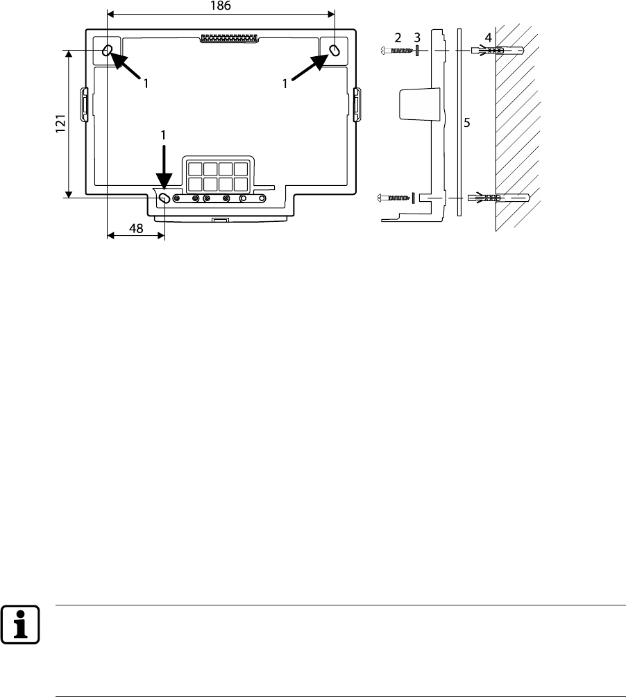
5.3 Fastening the docking station
First make the required cut-outs for introducing the installation line(s). Introduce the install-
ation lines from below or from the rear.
Fastening the docking station, dimensions in mm.
The docking station is mounted directly to the wall using screws/dowels. There are three oval
fastening holes(1) in the docking station for fastening.
Fastening material (included in the delivery):
• 3 wood screws Ø 4.5 x 35 (2)
• 3 washers (3)
• 3 dowels 6 mm (4)
The washers (3) cover the fastening hole (1) completely after tightening the screw. The de-
livered washers must also be used if you use other fastening screws (depending on the
mounting surface).
In case of soft mounting surfaces, make sure that the housing is not pressed into the surface
when mounting it.
The unevenness of the mounting surface may not exceed 0.5 mm. The unevenness of the
mounting surface may have to be compensated for or adjusted by means of suitable meas-
ures (e.g. washers).
If the mounting surface is not even, we recommend using the mounting plate (5). It is placed
between the wall and the docking station. The relatively rigid mounting plate avoids mechan-
ical distortion of the docking station.
The mounting plate is available as accessory under the order number 04043450.
InstallationTechnical Manual
4504043552 - 05/2017 Terminal 97 00DRAFT
5.4 Connections
Establish connections in de-energized state only!
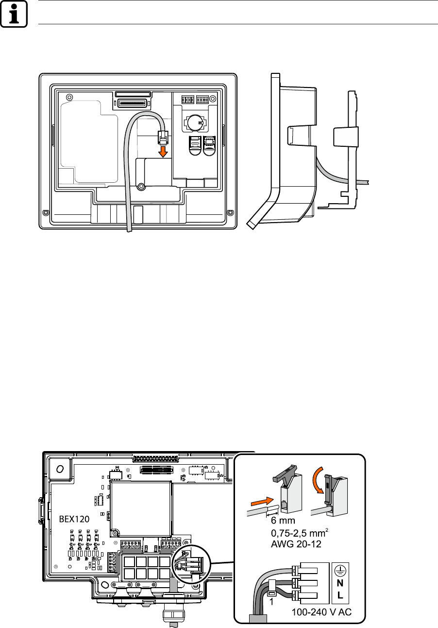
5.4.1 Connecting the network cable
The Ethernet connection (RJ45 socket) is located on the rear of the terminal housing.
The network cable should protrude approx. 15 to max. 18 cm from the wall so that the dis-
tance between docking station and terminal housing is enough to easily plug in the network
connector.
The network cable is then stored in a loop in the pocket on the rear of the terminal housing.
5.4.2 Connecting the mains voltage
Only devices with BEX120 motherboard!
üInstallations at the mains voltage may only be executed by a trained electrical specialist.
üThe mains line is de-energized.
1. Connect the mains line to the terminal.
2. Secure the N and L wires with a cable binder (1).
Installation Technical Manual
46 04043552 - 05/2017Terminal 97 00 DRAFT
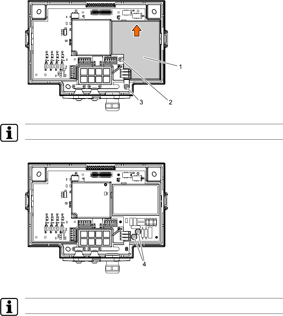
5.4.3 Mains fuses
Only devices with BEX120 motherboard!
The mains fuses are located under the sheet metal cover (1). Remove the cover in the follow-
ing way:
üThe mains power supply is off.
1. Unscrew the screw (2), TORX T10.
2. Unscrew the M4 nut (3) using a wrench with size 7.
3. Push the sheet metal cover (1) slightly upwards (unhinge it) and remove it
The mains voltage is secured with fuses on 2 poles.
The fuses (4) are of the plug-in type and can be easily replaced.
4 = 2x subminiature fuse (radial) T 1.0 A/250 V, order number 04037221
The fuses may only be replaced with fuses of the same type.
InstallationTechnical Manual
4704043552 - 05/2017 Terminal 97 00DRAFT
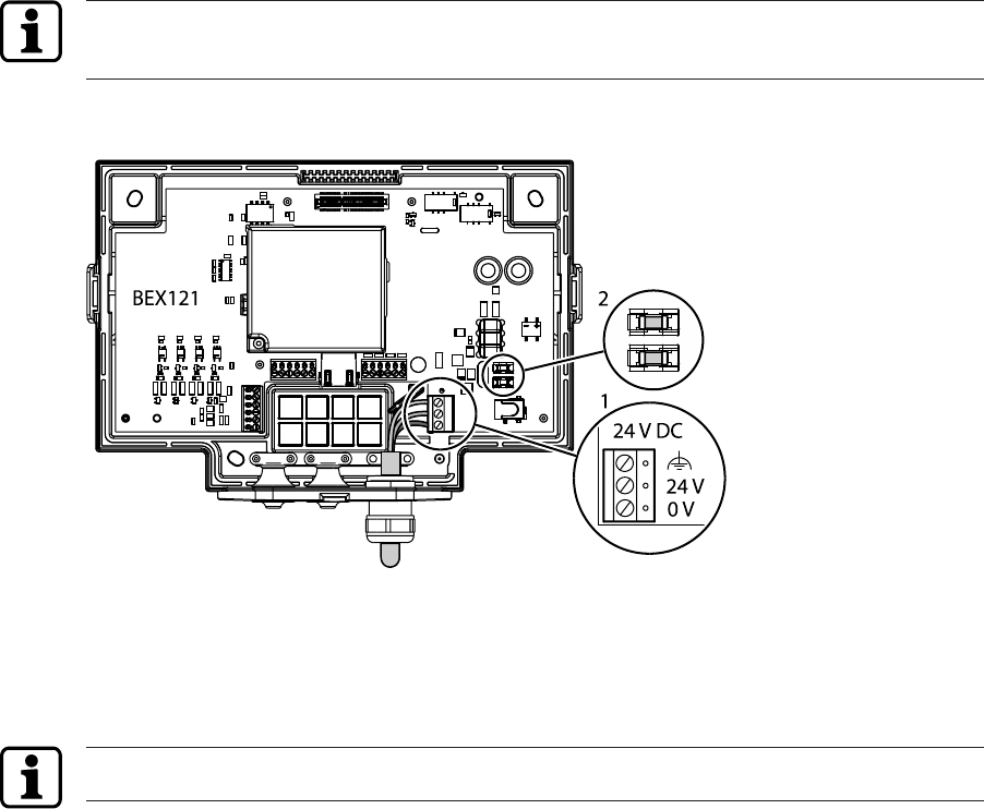
5.4.4 Connecting 24 V DC power supply
Only devices with BEX121 motherboard!
For the power supply of the device, use only power supply units that fulfil the requirements to
EN60950-1:2006 as limited power source.
Connect the 24 V DC power supply and the ground wire to the terminal (1).
Fuses for the 24 V DC power supply
The 24 V DC power supply is secured with fuses on 2 poles. The fuses (2) are of the plug-in
type and can be easily replaced.
2 = SMD fuse T 1.0 A/125 V, order number 04036925
The fuses may only be replaced with fuses of the same type.
Installation Technical Manual
48 04043552 - 05/2017Terminal 97 00 DRAFT
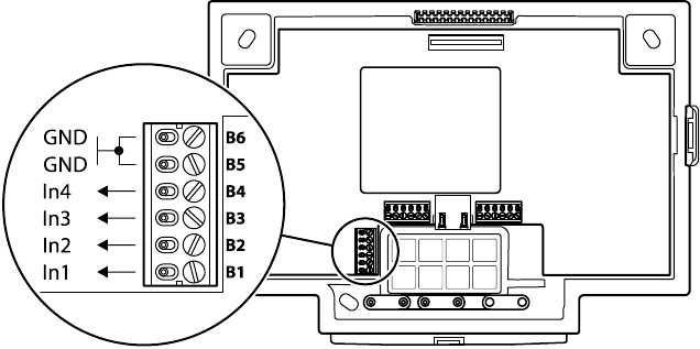
5.4.5 Digital inputs
Only devices with optional motherboard and B-Client HR30 ‘Door control’ software option.
4 digital inputs are available. The inputs can be used for a door opener key, access control or a
customized application.
Assignment of inputs E1 to E4 depends on the configuration.
The inputs can be controlled by a simple switch or a relay contact. The corresponding input is
connected to common ground. An open input is recognized as ‘high’ due to the internal pull-up
resistor. Ground potential equals ‘low’.
Level
High = + 4.5 V to + 30 V or open
Low = - 30 V to + 1.5 V
InstallationTechnical Manual
4904043552 - 05/2017 Terminal 97 00DRAFT
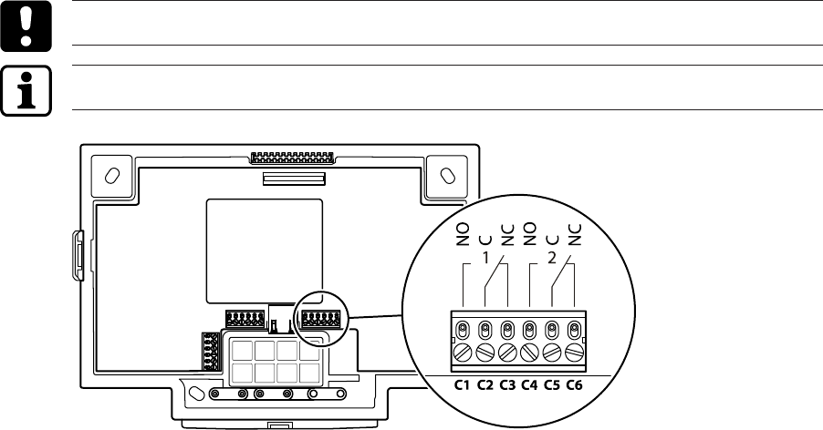
5.4.6 Relay outputs
Only devices with optional motherboard and B-Client HR30 ‘Door control’ software option.
Two potential-free relay outputs with one change-over contact each are available.
Contact loading capacity: 30 V AC/DC; max. 2 A
The function and assignment of relays 1 + 2 depend on the settings of the terminal software.
For inductive loads that are supplied with direct current, the included diode (a freewheeling
diode) must be connected parallel to the load to suppress interference. Make sure that the di-
ode is connected in reverse-bias direction. When using an AC voltage power supply, the in-
cluded varistor type S10K30 must be connected in parallel.
The diode or varistor must be connected directly to the load and must not be fitted in the ter-
minal.
Installation Technical Manual
50 04043552 - 05/2017Terminal 97 00 DRAFT
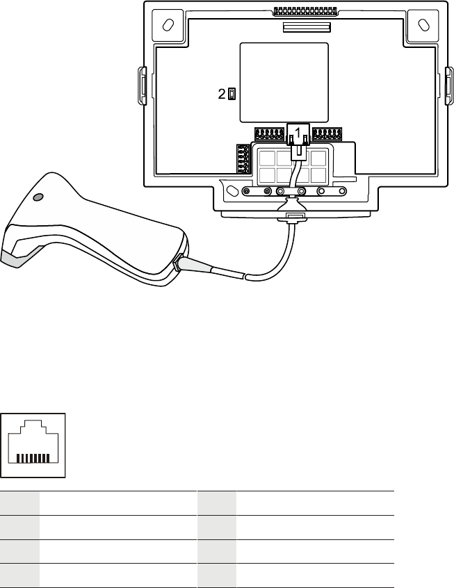
5.4.7 Connecting an external reader
Only devices with optional motherboard!
An additional external reader, for example a CCD barcode scanner, can be connected to the
device.
The reader can be connected to the COM4 port of the device. Further hardware and software
options are not required.
To ensure correct function, the reader must be configured and activated via the Service inter-
face [}6.5] or the Kaba test program [}6.4.2].
1 RJ45 connection for reader with RS-232C levels.
The barcode scanners provided by Kaba as accessories work with RS232C levels.
2 Fuse for the power supply of the external reader,
SMD fuse T375 mA, order number 04107874
Assignment of the RJ45 socket (1)
1
8
1 5 V DC; max. 300 mA 5 TxD (of the reader)
2 - 6 -
3 GND 7 -
4 - 8 -
Hardware handshake is not supported, no transmission delay for scanner data, communica-
tion parameters: 9600, 8, N, 1 (can be set).
Power supply for the reader
The power supply of the external reader can take place via the 5 V DC of the RJ45 socket. The
maximum allowed current is 300 mA.
InstallationTechnical Manual
5104043552 - 05/2017 Terminal 97 00DRAFT
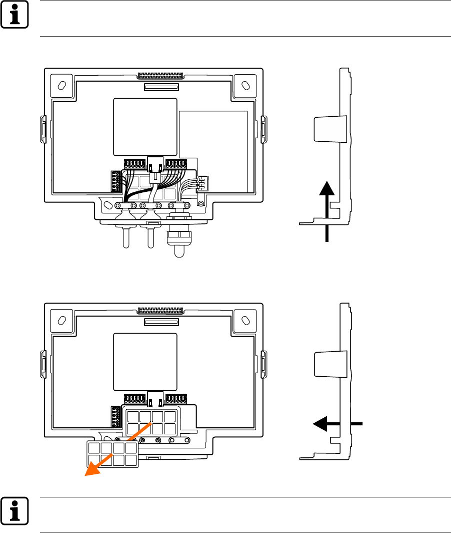
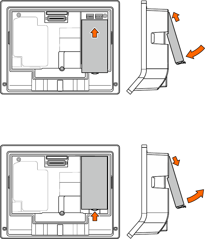
5.5 Uninterruptible power supply UPS510
The device may optionally be equipped with the uninterruptible power supply UPS510. The
UPS510 is snapped into place on the rear side of the terminal housing. The UPS510 can be ret-
rofitted at any time.
Inserting UPS510
To hold the UPS510, a recess is located on the rear of the terminal. The contact is located in
the upper part.
1. Slide the UPS510 with the contact on the underside forward into the recess as far as it
will go.
2. Press the lower part of the UPS510 against the terminal until the holder locks into place.
Removing UPS510
1. Unlock USSV510 by pressing the detent lever towards the UPS.
2. Extract the lower part of the UPS510 and then pull it downwards and remove it.
Installation Technical Manual
52 04043552 - 05/2017Terminal 97 00 DRAFT
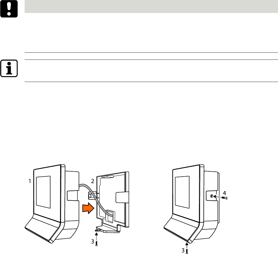
5.6 Fasten the terminal housing to the docking station.
NOTICE
For safety reasons (device safety and personal protection), the electronic components and
connections in the docking station may not be openly accessible.
Therefore, the terminal must be installed directly after the docking station if you use devices
with optional motherboard in the docking station.
For devices with docking station without motherboard (PoE), the terminal housing may also
be installed later on.
Fasten the terminal housing (1) as follows to the docking station (2):
1. Plug the network cable into the RJ45 socket on the rear of the terminal housing and lay
the cable in a loop in the pocket on the rear of the terminal housing.
2. Push the terminal housing (1) into the docking station (2) until the lateral tabs (3) lock into
place. Make sure that the terminal housing does not get jammed!
3. Secure the terminal housing on the docking station with the safety screw M4x10 TORX-TR
(3). This requires a SoftFinish® TORX® T20H screwdriver with a bore in the tip for TORX®
screws with locking pin.
Only devices with optional ‘screw-in wall-mounted version’.
1. Screw countersunk screws (4) into the tabs. This requires a TORX® T8 screwdriver.
CommissioningTechnical Manual
5304043552 - 05/2017 Terminal 97 00DRAFT
6 Commissioning
6.1 Network requirements
Start-up and communication in regular operation are done via an Ethernet network.
To guarantee unhindered and trouble-free data traffic, the UDP ports used for communica-
tion must have been enabled.
The firewall configuration must therefore be adapted accordingly.
6.1.1 Communication
The UDP port used for communication between B-COMM and the terminal must have been
enabled.
The UDP port is in the range from 7700 hex. to 77EF hex. (30464 dec. to 30703 dec.), depend-
ing on configuration.
6.1.2 Comparing finger templates
Devices equipped with a biometric CBM reader require another UDP port for exchanging bio-
metric data.
The UDP port used for the FTCS or BCFTC stream must have been enabled.
The UDP port is in the range from 7800 hex. to 78EF hex. (30720 dec. to 30959 dec.), depend-
ing on configuration.
6.1.3 Automatic registration via B-COMM
The network must have been equipped with a working DHCP server.
It must be possible to transfer UDP data packages unhindered to the B-COMM server.
• IP address 239.255.255.250, UDP port 1900 dec. and UDP port 7900 (30976dec.) must
have been enabled.
• The SSDP service has to be enabled in the Windows service management.
• The SFTP connection via the standard port 22 must have been enabled.
Commissioning Technical Manual
54 04043552 - 05/2017Terminal 97 00 DRAFT
6.2 Automatic registration via B-COMM
Start-up of the terminal takes place largely automatically in connection with the communica-
tion software B-COMM.
The device is preset at the factory for automatic registration via B-COMM.
For communication via WLAN, the connection must have been previously set up and activ-
ated. This is done via the system settings.
System requirements
• B-COMM communication software version 4.0 and higher.
• Network with a working DHCP server.
Start-up procedure
1. Connect the power supply for the device.
ðAfter booting, the device cyclically reports to the B-COMMs active in the network.
ðAt this point, until start-up by a
B-COMM is complete, the message ‘Waiting for registration’ is displayed on the dis-
play.
ðOnce the device is detected by B-COMM, the relevant data that identifies the device
will be queried.
ðIf the device is not known, it will be entered in B-COMM under the
B-COMM Terminal Discovery client under BCTDS (Terminal Discovery Stream).
2. Add device in B-COMM to the desired communication channel.
3. Provide device with the appropriate communication parameters.
ðAfter having assigned the device permanently to B-COMM, B-COMM first updates
the settings of the device and then makes a backup of the settings together with the
'sop.ini’ licence file.
ðThe device now reports to the B-COMMs active in the network that registration has
been carried out, after which the device will be removed again from the BCTDS
stream by the other B-COMMS.
4. Load specific parameters and master records to the device.
ðThe terminal software is restarted automatically. After that, the device is ready-to-oper-
ate.
6.2.1 Cancelling automatic registration
Automatic registration via B-COMM can be cancelled, in order to perform settings, for ex-
ample, manually.
üThe device is waiting for registration by B-COMM. The message ‘Waiting for registration’
is shown on the display.
1. Touch the Back icon in the navigation bar.
2. Confirm cancellation.
ðCancellation takes place after no more than 10 seconds, followed by starting the terminal
software.
The device can be reset to the registration mode via the Service Interface.
CommissioningTechnical Manual
5504043552 - 05/2017 Terminal 97 00DRAFT
6.3 Manual settings
Configuration and parameter setting of the terminal are done largely via the
B-COMM communication software.
Manual settings can be made locally on the device or from a remote location.
Settings locally on the device:
• Settings via the Service interface [}6.5]
• Settings via the Kaba test program [}6.4]
• Android system settings [}6.6]
Options for making settings from a remote location:
• Remote setup [}6.9]
• Service Interface [}6.5]
Network settings
To change network settings, for example assignment of a fixed terminal IP address, the fol-
lowing options are available:
• Locally on the device via Android system settings [}6.6]
• Locally on the device via Service interface [}6.5]
• Remote via the Service interface [}6.5]
Condition: The device must already have an IP address, which must be known.

Commissioning Technical Manual
56 04043552 - 05/2017Terminal 97 00 DRAFT
6.4 Settings via the Kaba test program
The Kaba test program is in general installed on the device. Apart from various test and info
functions, the Kaba test program also offers the option to make system-specific settings,
such as the configuration of the readers.
Loading the settings of the Kaba test program
üThe start screen of the Base App [}7.9] is displayed.
1. Touch the icon designated ‘TP’.
ðThe Kaba test program is started.
2. Select ‘Settings’.
ðThe settings of the Kaba test program are displayed.
6.4.1 Service language
This function allows you to select the language for service texts and the Kaba test program.
6.4.2 Reader settings
Configuration of the internally and externally connected readers.
These reader settings correspond to the device configuration at the time of delivery. The func-
tion is usually only required if an external reader is connected at a later stage or if LEGIC is
switched over to MIFARE in connection with an MRD reader.
CommissioningTechnical Manual
5704043552 - 05/2017 Terminal 97 00DRAFT
6.4.2.1 Reader type
Depending on the device, up to three readers can be configured. The reader type connected to
the respective interface is set under ‘Type’. If no reader is available, ‘NONE’ must be set as
reader type.
Type Supported readers
NONE No reader connected
LEGIC_4200 RMs SM-4200 LEGIC advant & SM-4200-M (MRD in LEGIC
mode)
MIFARE Kaba MIFARE (ARIOS security concept)
MIFARE_4200 RMs SM-4200-M (MRD in MIFARE mode)
BIOMETRIC_CBM Biometric CBM reader
HID_ICLASS_SE_PROX HID iCLASS SE / prox reader
HID_PROX HID proximity reader
HID_ICLASS HID iCLASS reader
BARCODE Barcode, CCD barcode scanner
MAGNETIC Magnetic swipe, Baltech MIFARE, Hitag
SPECIAL2 Reader with serial FLI2/FLI3
SPECIAL Reader with serial FLI
TRANSPARENT Special applications
Devices with MRD reader (multi-reader device)
Devices with MRD reader (RMs SM-4200-M) support LEGIC or MIFARE media, depending on
the reader type set.
For LEGIC media, the ‘LEGIC_4200’ reader type has been factory-preset.
For processing MIFARE media, the reader type must be changed to ‘MIFARE_4200’.
LEGIC media are configured in the same way as pure LEGIC readers by means of an
SM-4200 chip via the files ‘mediaact.ini’ and ‘mediadef.ini’.
MIFARE media are configured in the same way as the predecessor ‘Kaba MIFARE’ via the ‘sys-
tem.ini’ file.
6.4.2.2 Interface
To set the interface the reader is connected to.
The device supports up to three readers. Depending on options, the reader assignment of the
COM ports is as follows:
First internal reader Second internal reader External reader
COM2 (RFID) - COM4
COM2 (substructure reader) - COM4
COM2 (RFID) COM1 (substructure reader) COM4
COM1 (CBM) - COM4
COM1 (CBM) COM2 (RFID) COM4
COM1 (CBM) COM2 (substructure reader) COM4
Commissioning Technical Manual
58 04043552 - 05/2017Terminal 97 00 DRAFT
6.4.2.3 Guard time
The guard time is used to avoid accidental double bookings. After a booking, the next badge
will not be read until the guard time has expired.
The time is given in ms. Presetting = 2000 ms.
CommissioningTechnical Manual
5904043552 - 05/2017 Terminal 97 00DRAFT
6.5 Service Interface
The service interface provides the functions that are required for start-up, maintenance, and
diagnostics of the device.
Operation and a detailed description of the service functions can be found in the following
documentation:
• Service Interface reference manual
6.5.1 Remote access
The service interface is provided by the web server integrated into the device. Access takes
place via the network connection of the device, either directly or via the network. For direct
connection, an Ethernet cross-over cable (crossed RJ-45 cable) or an Ethernet patch cable 1:1
can be used (Auto MDIX).
The service interface can be accessed from a service PC via a web browser by typing the
device IP address into the address box.
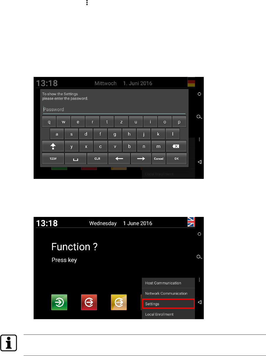
Commissioning Technical Manual
60 04043552 - 05/2017Terminal 97 00 DRAFT
6.5.2 Accessing the service interface locally from the B-Client HR30
terminal software.
Access the service interface from the B-Client HR30 terminal software
üB-Client HR30 terminal software has been started [}7.9.1] and is in the Basic view.
1. Touch the Back icon in the navigation bar [}7.4].
By default, the actuating time is 4 seconds, but can be adjusted to between 1 and 15
seconds.
ðAfter the set actuating time has expired, the password prompt appears.
2. Enter a password or leave the field empty if no password has been stored.
NOTE: No password has been stored for the device in its delivery state. A password can be
assigned using the parameter records X02/X12. See reference manual of the terminal
software.
3. Press ‘OK’ to confirm.
NOTICE! Three invalid password entries will lock the dialog. It must then be unlocked via
the parameter record I2.
4. Select ‘Settings’.
ðThe start page of the service interface appears on the display.
Without any touch interaction, the service interface will be automatically closed again after 3
minutes.
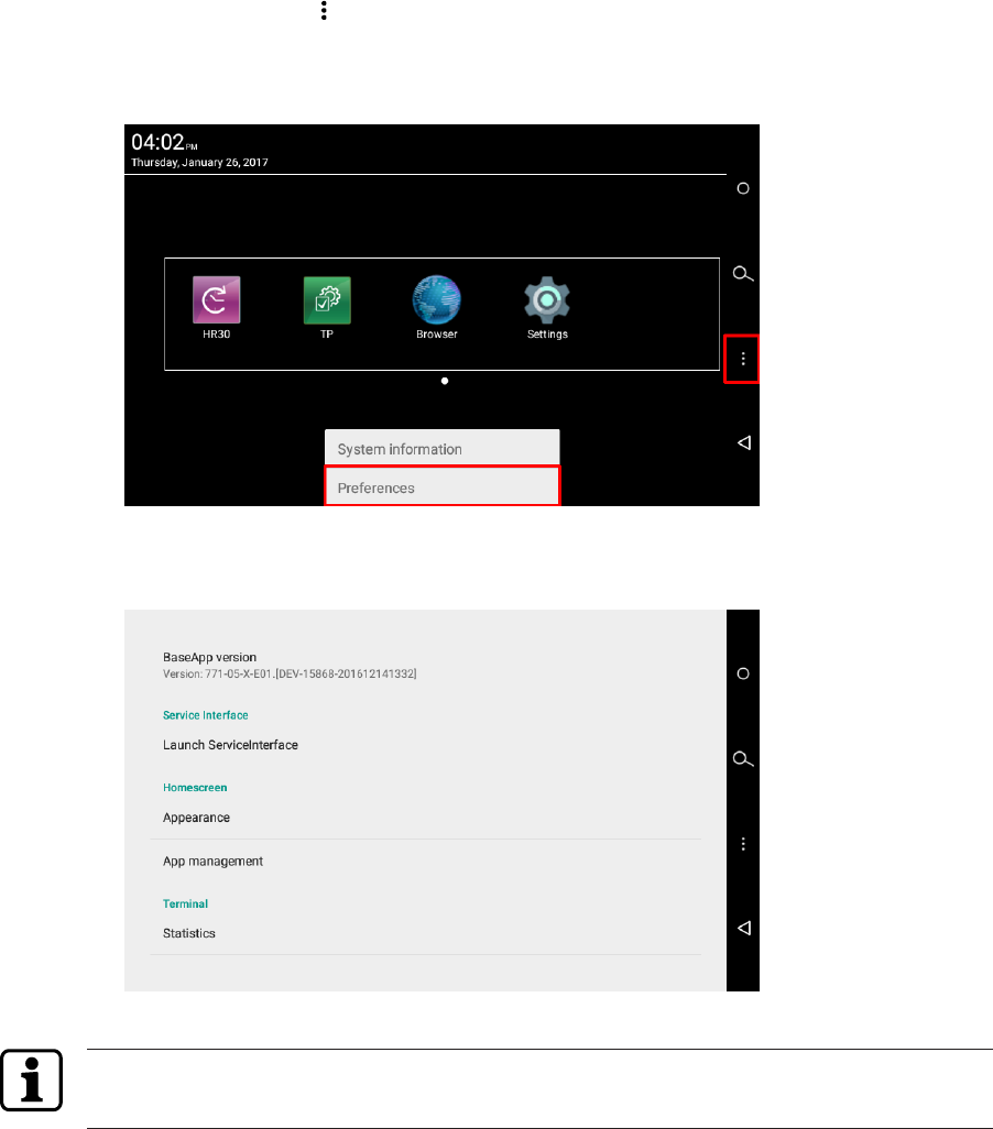
CommissioningTechnical Manual
6104043552 - 05/2017 Terminal 97 00DRAFT
6.5.3 Accessing the service interface locally from the BaseApp
Access the service interface from the BaseApp.
üThe start screen of the Base App is displayed.
1. Touch the Back icon in the navigation bar [}7.4].
ðA menu appears in the lower display area
2. Touch ‘Preferences’
ðA BaseApp function selection is displayed.
3. Touch 'Launch Service Interface' under Service Interface.
ðThe start page of the service interface appears on the display.
Without any touch interaction, the service interface will be automatically closed again after 3
minutes.
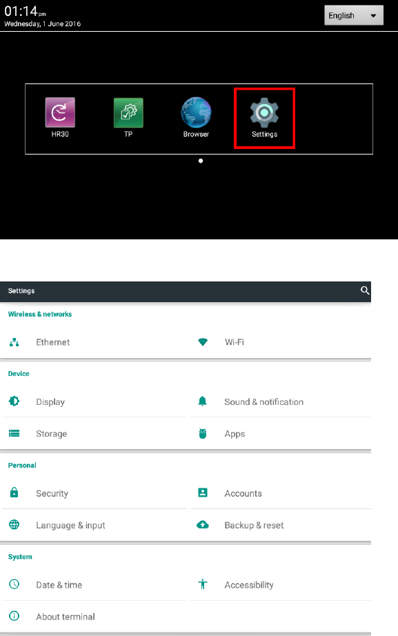
Commissioning Technical Manual
62 04043552 - 05/2017Terminal 97 00 DRAFT
6.6 Android system settings
System-specific settings, connection settings, such as assignment of a fixed IP address, can
be made via the android system settings.
Access the android system settings
üThe start screen of the Base App is displayed.
1. Touch the ‘Settings’ application.
ðThe main menu of the android system settings is displayed.
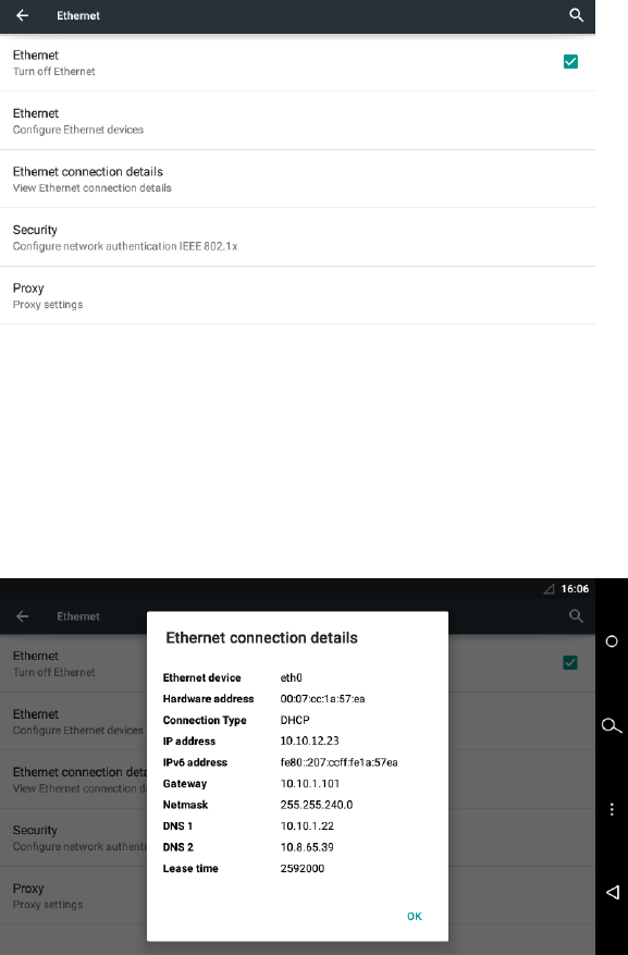
CommissioningTechnical Manual
6304043552 - 05/2017 Terminal 97 00DRAFT
6.6.1 Network settings
Open the Ethernet menu:
üThe main menu of the android system settings is displayed.
1. Select ‘Ethernet’ under ‘Wireless & networks’.
ðThe menu containing the Ethernet functions is displayed.
6.6.1.1 Displaying the current network configuration
üThe menu containing the Ethernet functions is displayed.
1. Select ‘Ethernet connection details’.
ðThe current network configuration is displayed.
Example:
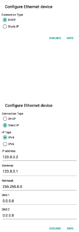
Commissioning Technical Manual
64 04043552 - 05/2017Terminal 97 00 DRAFT
6.6.1.2 Adjusting the Ethernet settings
üThe menu containing the Ethernet functions is displayed.
1. Select ‘Ethernet - configure Ethernet devices’
ðThe Ethernet settings are displayed
Requesting an IP address from the DHCP server
1. Activate ‘DHCP’.
2. Apply setting by pressing ‘Save’ and leave the function.
Static IP configuration
1. Activate ‘Static IP’.
2. Enter network parameters.
3. Apply setting by pressing ‘Save’ and leave the function.
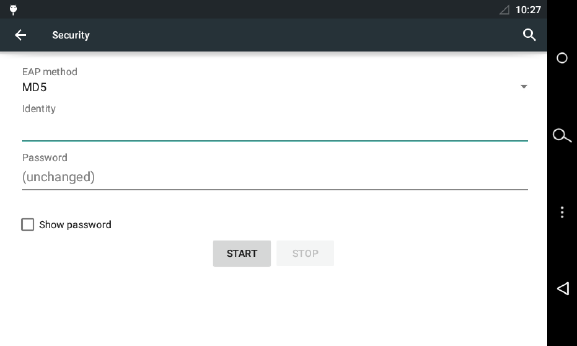
CommissioningTechnical Manual
6504043552 - 05/2017 Terminal 97 00DRAFT
6.6.1.3 Network security
The terminal supports the following authentication procedure for access controls to the local
network:
• EAP (Extensible Authentication Protocol) according to IEEE 802.1x
• EAP type MD5 with identity and password
Configuration of IEEE 802.1x authentication
üThe menu containing the Ethernet functions is displayed.
1. Select ‘Configure network authentication IEEE 802.1x’ under ‘Security’.
2. Select EAP method (MD5), enter identity and password.
3. Touch ‘Start’
Commissioning Technical Manual
66 04043552 - 05/2017Terminal 97 00 DRAFT
6.6.2 Settings for adjustment to the environment
Display brightness
The display brightness can be adjusted as follows:
üThe main menu of the android system settings is displayed.
1. Select ‘Display‘ under ‘Device’.
ðThe display functions are displayed.
2. Select ‘Brightness level’.
3. Use the slide control to set the desired brightness.
Sleep setting
After a defined time without user activity, the display brightness is automatically reduced.
The time until this sleep mode is initiated can be set in a range between 15 seconds and one
hour. The sleep mode can also be deactivated.
The sleep setting can be adjusted as follows:
üThe main menu of the android system settings is displayed.
1. Select ‘Display‘ under ‘Device’.
ðThe display functions are displayed.
2. Select ‘Sleep’.
3. Select desired time or deactivate function (Never).
The sleep mode is finished when the internal motion sensor detects a person or any user activ-
ity takes place at the device.
Volume setting
The volume for the acoustic operator guidance via the system loudspeaker can be adjusted as
follows:
üThe main menu of the android system settings is displayed.
1. Select ‘Sound & notification’ under ‘Device’.
ðThe sound settings are displayed.
2. Use the ‘Media volume’ slide control to set the desired volume.
CommissioningTechnical Manual
6704043552 - 05/2017 Terminal 97 00DRAFT
6.7 Reader initialization
Some RFID readers must be initialized during initial start-up.
6.7.1 LEGIC
LEGIC readers require a reader launch in certain cases:
• If a read-protected segment is to be used.
• If writing to a write-protected segment is to be done, for example during a CardLink ap-
plication.
Reader launch
üThe reader launch requires an SAM 63 card (security card C2) containing the correspond-
ing segment area.
1. Hold the SAM 63 card in front of the reader if the device expects an RFID input in normal
operation.
ðThe start of the sequence is confirmed by means of an acoustic signal.
ðThree successive acoustic signals are output if the process cannot be executed, for ex-
ample if the reader has already been launched.
2. The SAM 63 card must be present uninterruptedly in the reading area for about 15-20
seconds.
ðAfter a successful launch, 3 short acoustic signals are output.
ðEight successive signals are output when an error occurs.
3. Remove the SAM 63 card from the field.
Reader delaunch
üThe reader is delaunched using an SAM 64 card.
1. Hold the SAM 64 card in front of the reader if the device expects an RFID input in normal
operation.
ðThe start of the sequence is confirmed by means of an acoustic signal.
ðThree successive acoustic signals are output if the process cannot be executed, for ex-
ample if the reader has already been launched.
2. The SAM 64 card must be present uninterruptedly in the reading area for about 15-20
seconds.
ðAfter a successful delaunch, 3 short acoustic signals are output.
ðEight successive signals are output when an error occurs.
3. Remove the SAM 64 card from the field.
Commissioning Technical Manual
68 04043552 - 05/2017Terminal 97 00 DRAFT
6.7.2 MIFARE (ARIOS)
In systems with ARIOS security concept, the site key must be distributed to the individual
readers.
The site key can be distributed in two ways.
• Site key distribution via B-COMM.
• Site key distribution via programming master A or B.
For details, please refer to the reference manual of the terminal software.
6.7.3 MIFARE (Baltech)
The MIFARE reader must be activated by a MIFARE configuration card:
1. Turn off the device.
2. Turn on the device.
3. Hold the MIFARE configuration card in front of the reader for about 10 seconds.
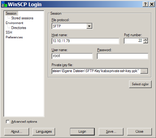
CommissioningTechnical Manual
6904043552 - 05/2017 Terminal 97 00DRAFT
6.8 SFTP server
The device provides an SFTP server for a secure, encrypted connection via the 'Secure File
Transfer Protocol’ (SFTP).
6.8.1 Preconditions
For SFTP access to the terminal, the following is required:
• SFTP client, for example WinSCP. WinSCP (Windows Secure CoPy) is a free 'open source’
SFTP and FTP client for Microsoft Windows.
• Kaba key file. The standard key file is available for download on the Internet at the Kaba
site in the secured area (Extranet).
• The SFTP connection via the standard port 22 must have been enabled.
6.8.2 Establishing an SFTP connection
After installation and start of the SFTP client, the login window appears.
Required settings:
File protocol: SFTP
Host name: <IP address> e.g. 10.10.11.79
Port number: 22
User name: root
Password: leave blank
Private key file: Select key file on local computer.
1. Make the following entries and settings
2. Click “Login”
.
3. Enter pass phrase.
Pass phrase for standard key = kaba
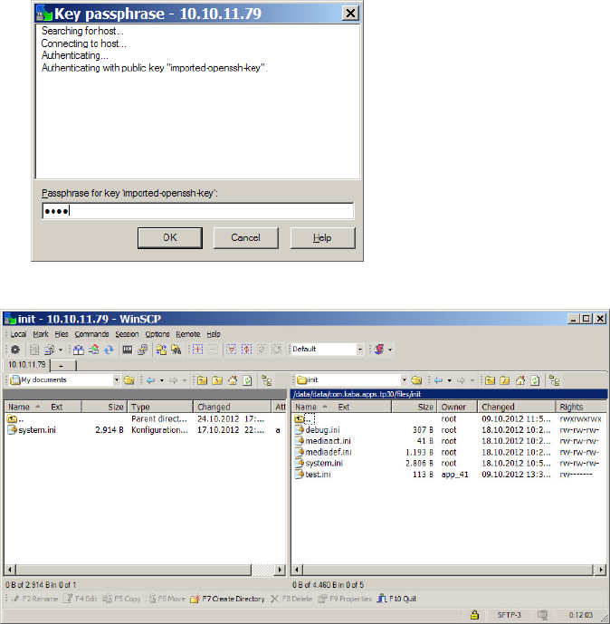
Commissioning Technical Manual
70 04043552 - 05/2017Terminal 97 00 DRAFT
4. Click "OK"
ðThe connection to the terminal is being established.
6.8.3 Information on the key file
The device is equipped with a standard key file ex works.
It can be replaced with an adjusted customized key file via the function 'SSH key replacement’
of the B-COMM communication software.
The SSH key can be reset to standard via the service interface or the BaseApp settings locally
on the device.

CommissioningTechnical Manual
7104043552 - 05/2017 Terminal 97 00DRAFT
6.8.4 Important directories and files
Path: /data/data/com.kaba.apps.hr/files/
Directory File Description
EEPROMsetting Parameter used for the system start
diagnosis statisticsHR.dat Statistics
init application.ini Settings of the B-Client terminal software
b-client_xml.ini HTTP/HTTPS/XML function parameters
encoding.ini Definition of special characters
interface.ini B-Client terminal software design
labelinfo.ini Info texts
sop.ini Software licence file
text.ini Texts for dynamic lists
SSL root.pem HTTPS certificates
root.crt
transfer record.dat Transfer directory for control files, see chapter
6.9
input.cmd
reboot.cmd
Path: /data/data/com.kaba.apps.ba/files/
Directory File Description
diagnosis debug.err Error logfile
debug.log System logfile
debug.bak Backup of debug.log
init communication.ini Communication settings
debug.ini Logging settings
mediaact.ini Settings for LEGIC 4200 reader
mediadef.ini
system.ini System settings
terminal.ini Terminal settings

Commissioning Technical Manual
72 04043552 - 05/2017Terminal 97 00 DRAFT
6.9 Remote setup
The following settings can also be transferred to the device via SFTP [}6.8]:
• Host configuration
• FTCS host configuration
• Reader settings
This type of start-up should only be carried out by experienced system specialists.
Procedure:
1. Establish SFTP connection to the device.
2. Load the following file in ASCII mode to the local computer:
/data/data/com.kaba.apps.hr/files/EEPROMsetting
This file contains the parameter used for the last start.
3. Rename file to reboot.cmd.
4. Adjust the parameter values in the file accordingly.
NOTE: Changes in the sections [General] and [Ethernet] will not be applied!
5. Enter ‘RESET’ in the first line of the file.
Example:
RESET
[Ethernet]
MAC Addr=00:07:cc:00:62:e4
Terminal Addr=10.10.5.85
...
6. Copy the reboot.cmd file to the following directory on the device:
/data/data/com.kaba.apps.hr/files/transfer/
ðThe file will be identified within approx. 15 seconds and the parameter values will be ap-
plied.
ðThe terminal software is then restarted with the changed settings.
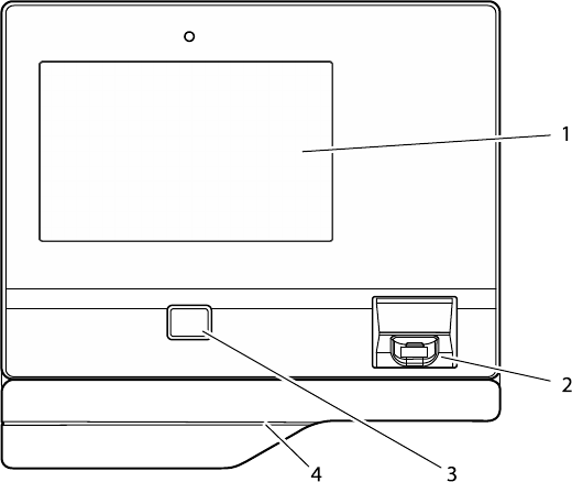
OperationTechnical Manual
7304043552 - 05/2017 Terminal 97 00DRAFT
7 Operation
7.1 Operating elements
1 Display and touch screen
2 Reader window for finger placement (only devices with optional biometric reader)
3 Entry field for RFID media (only devices with optional RFID reader)
4 Card swipe (only devices with optional swipe reader in substructure housing)
7.2 Display
For displaying the user interface and outputting specific information, a 7” colour TFT display is
used.
7.3 Touch screen
The device has a 7” touch screen, which extends over the entire display surface. The touch
screen is operated by touching the glass surface with a finger.
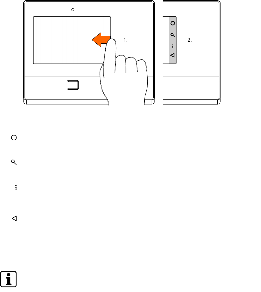
Operation Technical Manual
74 04043552 - 05/2017Terminal 97 00 DRAFT
7.4 Navigation keys
By wiping from the right display edge to the left, the navigation bar is displayed. The naviga-
tion bar contains the android navigation keys.
Upon touching the individual symbols, the following functions will be executed:
Home
Upon touching the Home symbol, the desktop view (start screen) of the device opens. Since
the android is capable of multitasking, active programs keep running in the background.
Search
Upon touching the search symbol, the search function for each active program is displayed.
Menu
Upon touching the menu symbol, a menu is displayed whose options refer to the current pro-
gram or the current screen display.
Back
Upon touching the Back icon, it is possible to return to the display view shown last in each
case, i.e., for example, from the submenu to the main menu.
When the system is expecting an input, a virtual keypad is shown on the display. In this input
mode, the Back icon points downwards. Upon touching the Back icon, the input mode is fin-
ished, and the virtual keypad disappears.
The Home key and Search key are without function within the B-Client HR30 terminal soft-
ware, test program and BaseApp.
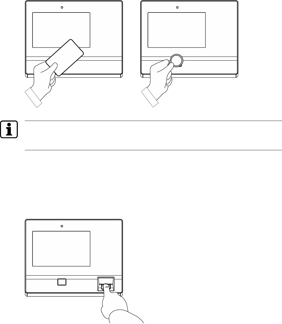
OperationTechnical Manual
7504043552 - 05/2017 Terminal 97 00DRAFT
7.5 RFID reader
Contact-free media are simply held in front of the entry field of the RFID reader on the ter-
minal.
The reading process, in particular in connection with biometric verification or CardLink, can
take several seconds. RFIDDo not remove the RFID medium from the input field until success-
ful read-in has been signalled.
7.6 Biometric reader
The biometric reader is ready as soon as the reading window is lit.
The finger must be placed in the centre of the reading window of the biometric reader.
After a valid booking, a short acoustic signal can be heard.
Finger position
Only if finger position and pressure on the reader window are optimal, is a correct fingerprint
read-in ensured.
• The finger has to be slightly humid.
• The finger has to be gently pressed onto the window.
• The fingerprint has to be in the centre of the reader window.
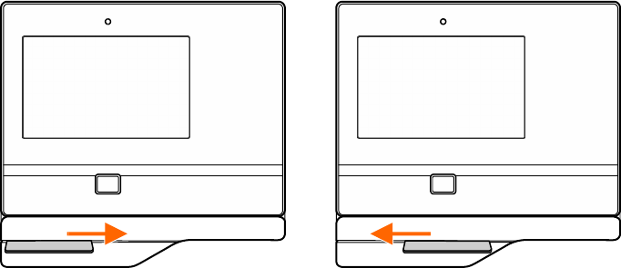
Operation Technical Manual
76 04043552 - 05/2017Terminal 97 00 DRAFT
7.7 Swipe reader
Swiftly swipe magnetic-stripe badges and barcode badges through the reading bar in any dir-
ection.
The magnetic stripe is on the back of the badge, pointing towards the scanning unit.
The barcode is on the front of the badge, pointing towards the scanning unit.
In connection with magnetic-stripe badges, automatic detection of the booking direction is
possible.
This function must be enabled by settings in the terminal software.
Thus, for example, swiping from left to right can generate an IN booking and swiping from
right to left an OUT booking.
OperationTechnical Manual
7704043552 - 05/2017 Terminal 97 00DRAFT
7.8 Symbols for user guidance
The following standard symbols are available to the terminal software for user guidance. The
symbols are part of the BaseApp.
Display contents, functions and operating sequences depend on the terminal software set-
tings.
7.8.1 Function keys
IN Production data collection
OUT CardLink
Official absence Cafeteria
Break Kiosk 1
Query Kiosk 2
Time query Logfile 1
Access 1 Logfile 2
Access 2 Logfile 3
Visitor registration Additional settings
Cloud News
Room reservation Shift schedule
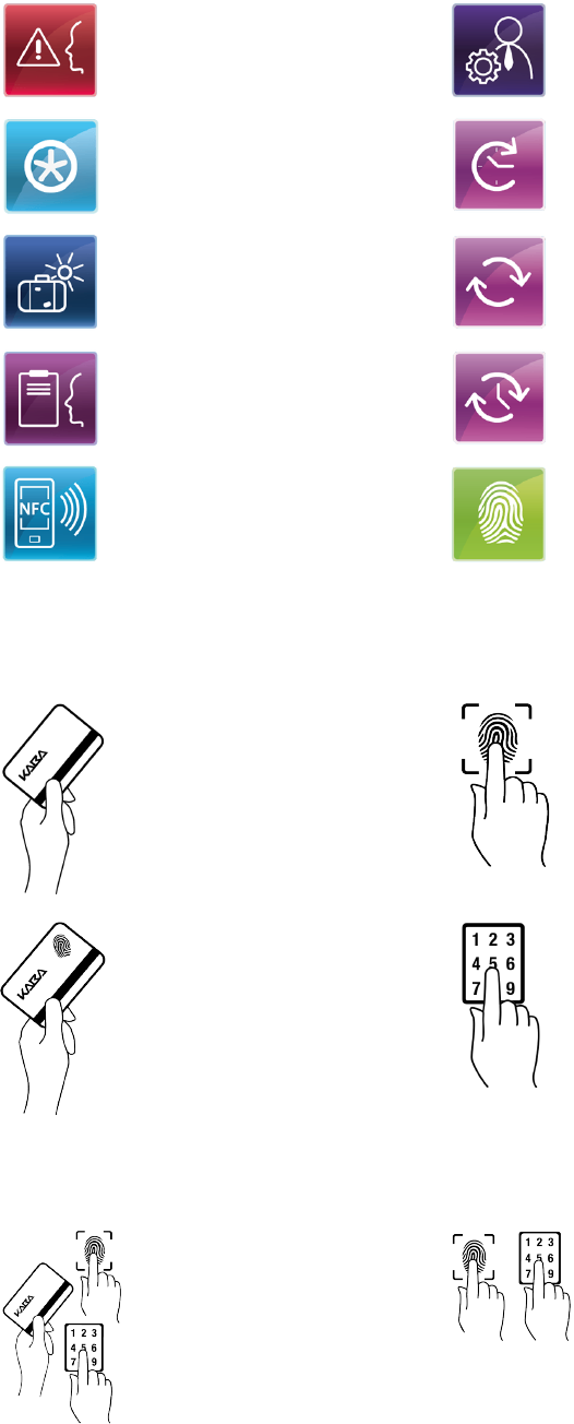
Operation Technical Manual
78 04043552 - 05/2017Terminal 97 00 DRAFT
Briefing Master records
Special function Time and attendance 1
Holiday Time and attendance 2
Survey Time and attendance 3
NFC Biometrics
7.8.2 Input prompt
The following symbols signal to the operator what entry is currently expected.
Badge entry via RFID reader or
swipe reader expected.
Finger entry via biometric reader
expected.
Entry of an RFID badge with bio-
metric segment for biometric
verification expected.
ID or PIN entry expected.
If the system configuration alternatively allows for several entries, symbols with several pos-
sible entry types are displayed, for example:
Finger entry or badge entry or
entry via keypad expected.
Finger entry or entry via keypad
expected.

OperationTechnical Manual
7904043552 - 05/2017 Terminal 97 00DRAFT
7.8.3 Error states
The following symbols signal to the operator error states during a booking
Invalid biometric verification
Fingerprint is not identical to the finger template on the badge or finger tem-
plate does not exist.
Invalid biometric verification
No biometric segment on badge detected or error while reading finger tem-
plate.
Invalid biometric identification
The database of the CBM reader does not contain any finger templates (data-
base empty).
Invalid biometric identification
Finger not contained in database
Reading error
7.8.4 CardLink
When using the optional CardLink function, the following symbols are relevant.
A CardLink update is available.
During a CardLink validation or CardLink update, an error has occurred.

Operation Technical Manual
80 04043552 - 05/2017Terminal 97 00 DRAFT
7.8.5 Finger entry
While the fingerprint is read in, the user is guided event-driven by the biometric reader.
The following symbols are displayed to signal the error states to the user.
Place finger more to the left.
Place finger more to the right.
Place finger more to the top.
Place finger more to the bottom.
Press finger more strongly.
Latent finger
Clean reading window of the biometric reader
The database of the CBM reader does not contain any finger templates
(database empty).
This state is displayed immediately after enabling the reader.
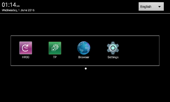
OperationTechnical Manual
8104043552 - 05/2017 Terminal 97 00DRAFT
7.9 BaseApp
The BaseApp is the user interface shown after closing an application.
The BaseApp essentially performs the following functions:
• Protection of the operating system from unauthorized access (system isolation).
• Only controlled access to the operating system is possible.
• Organization and start-up of applications (apps).
• Provision of functions and interfaces for access to the hardware.
7.9.1 Starting the application
On the start screen of the BaseApp, the applications (apps) available to the user are shown in
the form of symbols (icons).
Depending on the number of applications, this list can run over several pages. The number of
pages is indicated by the dots below the list. The active page is characterized by a filled dot.
Upon touching the corresponding icon, the application is started.
For example, Kaba terminal software:
• Icon HR30 = B-Client HR30 terminal software
• Icon TP = Kaba test program
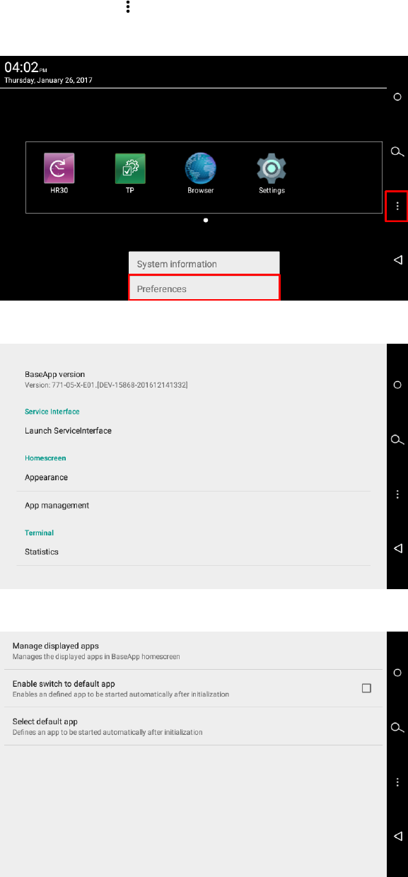
Operation Technical Manual
82 04043552 - 05/2017Terminal 97 00 DRAFT
7.9.2 App management
This function determines which applications (apps) are displayed on the start screen and are
thus available to the operator. The order of the app icons can also be adjusted.
In addition, a default application started automatically with the system can be defined.
Starting app administration
üThe start screen of the Base App is displayed.
1. Touch the Back icon in the navigation bar [}7.4].
2. Select ‘Preferences’.
3. Select ‘App management’.
ðThe submenu of the app management is displayed.
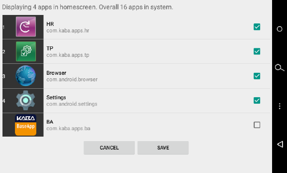
OperationTechnical Manual
8304043552 - 05/2017 Terminal 97 00DRAFT
7.9.2.1 Managing the apps displayed
The available applications (apps) are displayed in a list.
To place an app on the BaseApp start screen, the check box on the right must be checked.
On the left next to the app icon, the order number is shown. The order number indicates the
order of the apps on the BaseApp start screen. To change the order, touch the icon of the cor-
responding app and move it to the desired position in the order.
7.9.2.2 Autostart for default app.
If the function ‘Enable switch to default app’ is active, the application defined under ‘Select
default app’ will be started automatically when starting the device.
7.9.2.3 Selection of the default app
The function ‘Select default app’ is used to define the default app.
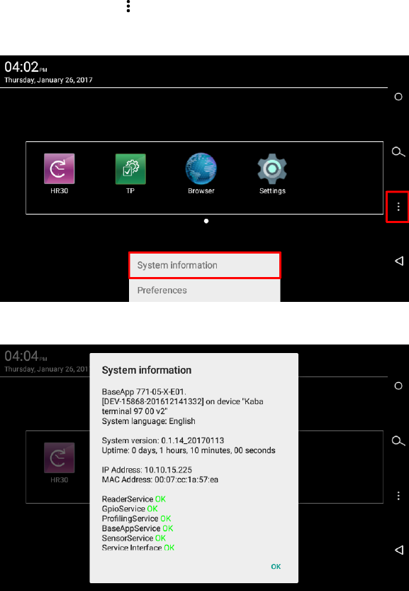
Operation Technical Manual
84 04043552 - 05/2017Terminal 97 00 DRAFT
7.9.3 System Information
The BaseApp menu can be used to display miscellaneous system information.
Displaying system Information
üThe start screen of the Base App is displayed.
1. Touch the Back icon in the navigation bar [}7.4].
2. Select ‘System Information’.
ðThe system information is displayed.
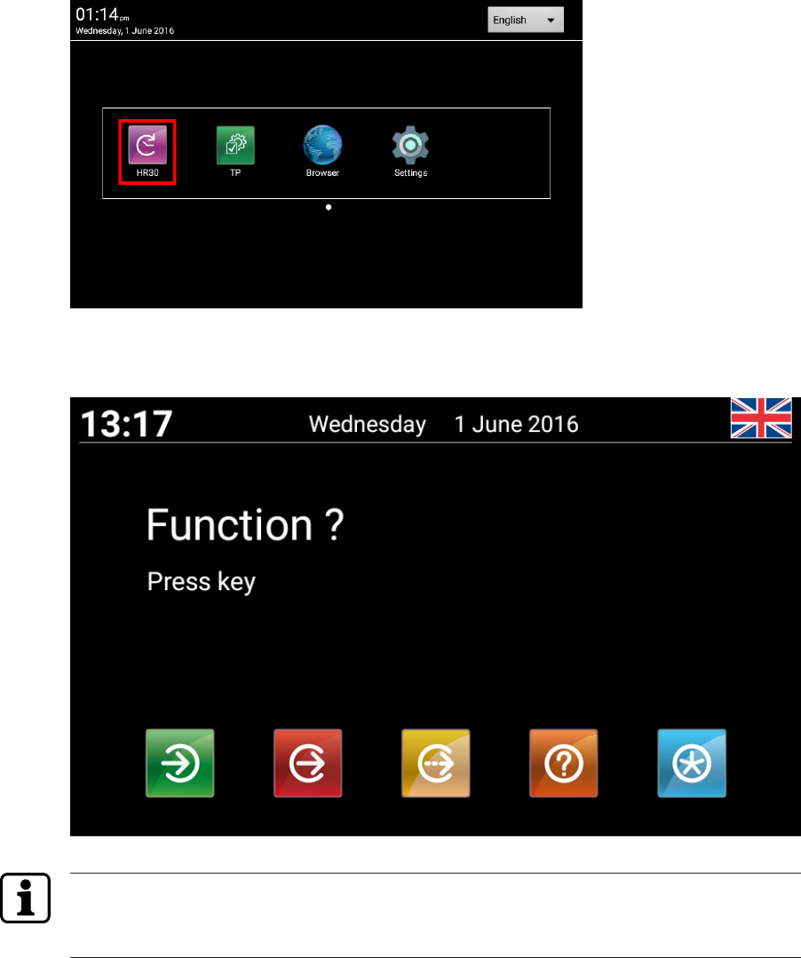
OperationTechnical Manual
8504043552 - 05/2017 Terminal 97 00DRAFT
7.10 B-Client HR30 terminal software
7.10.1 Starting the terminal software
In the start screen of the BaseApp [}7.9], the available applications (apps) are displayed.
Touch the icon designated ‘HR30’ to start the B-Client HR30 terminal software.
The B-Client HR30 user interface is shown on the display of the terminal.
The appearance of the device software can be adjusted specifically for each customer and is
therefore variable. Accordingly, the default user interface shown above must be considered an
example.
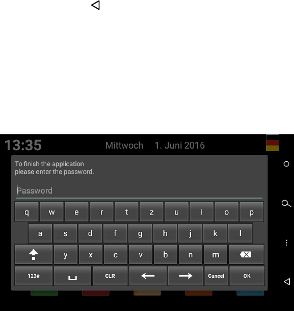
Operation Technical Manual
86 04043552 - 05/2017Terminal 97 00 DRAFT
7.10.2 Shutting down the terminal software
Shut down the B-Client terminal software as follows:
1. Touch the Back icon in the navigation bar [}7.4].
NOTE: By default, the actuating time is 4 seconds, but can be adjusted to between 1 and
15 seconds.
ðAfter the set actuating time has expired, the password prompt appears.
2. Enter a password or leave the field empty if no password has been stored.
NOTE: No password has been stored for the device in its delivery state. A password can be
assigned using the parameter records X02/X12. See reference manual of the terminal
software.
3. Press ‘OK’ to confirm.
NOTICE! Three invalid password entries will lock the dialog. It must then be unlocked via
the parameter record I2.
ðThe terminal software is shut down, and the BaseApp user interface [}7.9] is displayed.
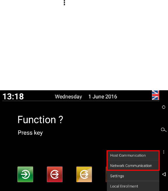
OperationTechnical Manual
8704043552 - 05/2017 Terminal 97 00DRAFT
7.10.3 Info functions
In the menu of the B-Client HR30 terminal software, two info functions are available.
üB-Client HR30 terminal software has been started. [}7.10.1]
1. Touch the Menu icon in the navigation bar [}7.4].
ðAfter the set actuating time has expired, the password prompt appears.
NOTE: By default, the actuating time is 4 seconds, but can be adjusted to between 1
and 15 seconds.
2. Enter a password or leave the field empty if no password has been stored.
NOTE: No password has been stored for the device in its delivery state. A password can be
assigned using the parameter records X02/X12. See reference manual of the terminal
software.
3. Press ‘OK’ to confirm.
ðThe menu is displayed.
Host communication
The following information is displayed:
• B-Client HR30 version
• Terminal IP address
• Host IP address and port
• Group identification and device identification
• Current readers
Network communication
The following information is displayed:
• Terminal IP address
• Network mask
• MAC address
• DNS
• Gateway
• DHCP server address
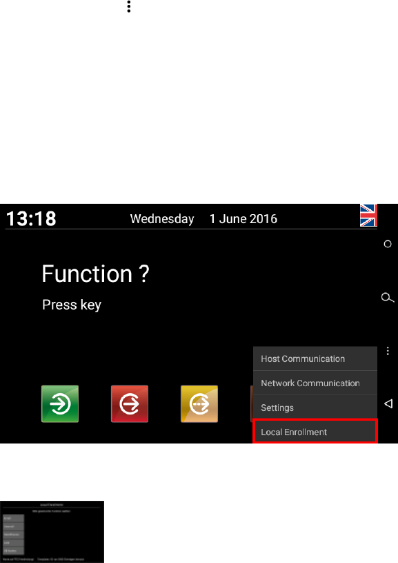
Operation Technical Manual
88 04043552 - 05/2017Terminal 97 00 DRAFT
7.10.4 Registering new fingerprints at the terminal
The function ‘Local Enrollment’ of the B-Client HR30 terminal software allows new finger-
prints to be registered via the biometric reader at the terminal.
Prerequisites:
• Terminal with biometric reader
• B-Client HR30 terminal software with ‘Local Enrollment’ software option
7.10.4.1 Displaying the function
üB-Client HR30 terminal software has been started [}7.10.1].
1. Touch the Menu icon in the navigation bar [}7.4].
ðAfter the set actuating time has expired, the password prompt appears.
NOTE: By default, the actuating time is 4 seconds, but can be adjusted to between 1
and 15 seconds.
2. Enter a password or leave the field empty if no password has been stored.
NOTE: No password has been stored for the device in its delivery state. A password can be
assigned using the parameter records X02/X12. See reference manual of the terminal
software.
3. Press ‘OK’ to confirm.
4. Select 'Local Enrollment'.
ðThe main menu is displayed. The biometric mode and the current assignment of the in-
ternal reader database are additionally displayed.
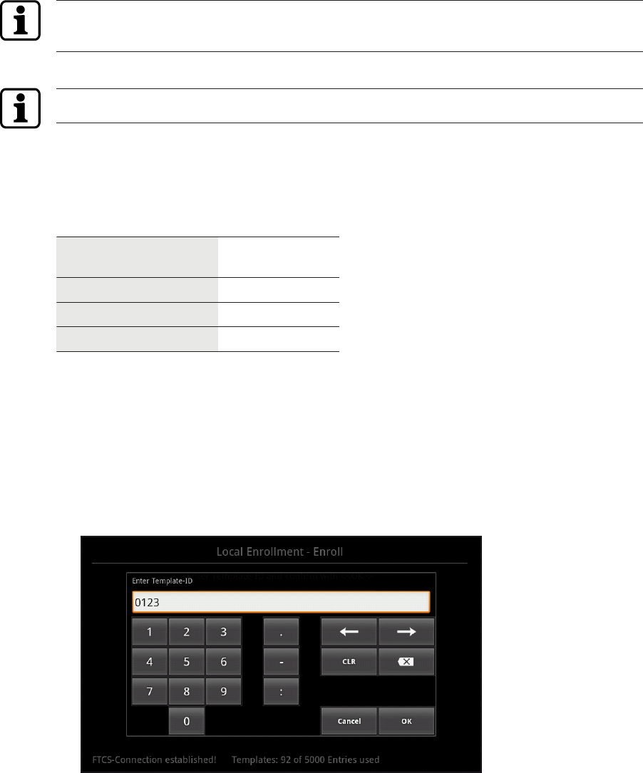
OperationTechnical Manual
8904043552 - 05/2017 Terminal 97 00DRAFT
7.10.4.2 Enroll
This function allows persons to be registered via the biometric reader of the terminal. The fin-
gerprints are stored in the internal reader database.
Operation with biometric software
During normal operation with biometric software, the new finger templates are synchronized
directly using the Finger Template Control Service (FTCS).
The function 'Enroll’ is only executed if an FTCS connection is already available via the BCFTC
stream.
Standalone mode
In standalone mode, the function is also executed without FTCS connection.
Procedure
2 fingers per person are registered. 3 pictures are taken of each finger. To do so, each finger
has to be briefly placed on the reader window three times. A quality value is specified for each
registration process.
The quality of the registered fingers is subdivided into three levels.
Quality of number Quality of text
> 120 very good
60-120 good
< 60 poor
Optimal finger position
If the finger position is not ideal during enrollment, symbols to that effect are shown on the
display [}7.8.5].
Registering a person
1. Select 'Enroll'.
2. Enter template ID.
NOTE: The person is identified by means of the template ID. The length of the ID is preset
by the 'PresetEnroll' parameter.
3. Press 'OK’ to confirm the template ID.
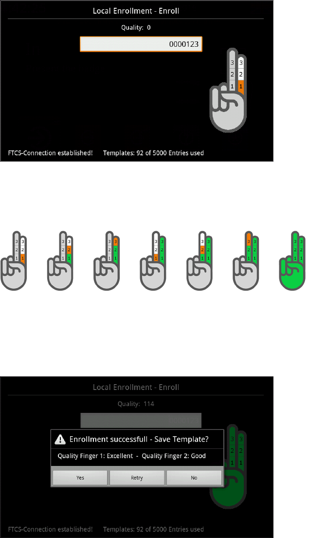
Operation Technical Manual
90 04043552 - 05/2017Terminal 97 00 DRAFT
4. Place first finger on the reading window.
ðA successful read-in of a finger is confirmed by means of a short acoustic signal.
5. Remove finger briefly and then place it again.
The hand symbol on the display signals which finger has to be placed which number of
times (orange) and which fingers have been registered how many times (green).
ðAfter successful registration of the 6 (2x3) finger prints, a green hand will be dis-
played.
ðAt the end of the procedure, the overall quality of the registered fingers and a prompt
will be displayed, asking you whether you want to save the template.
6. If you want the finger template to be saved, press 'Yes’ to confirm.
If the quality is poor, the procedure should be repeated. If the quality of a finger is re-
peatedly poor, a different finger should be registered.
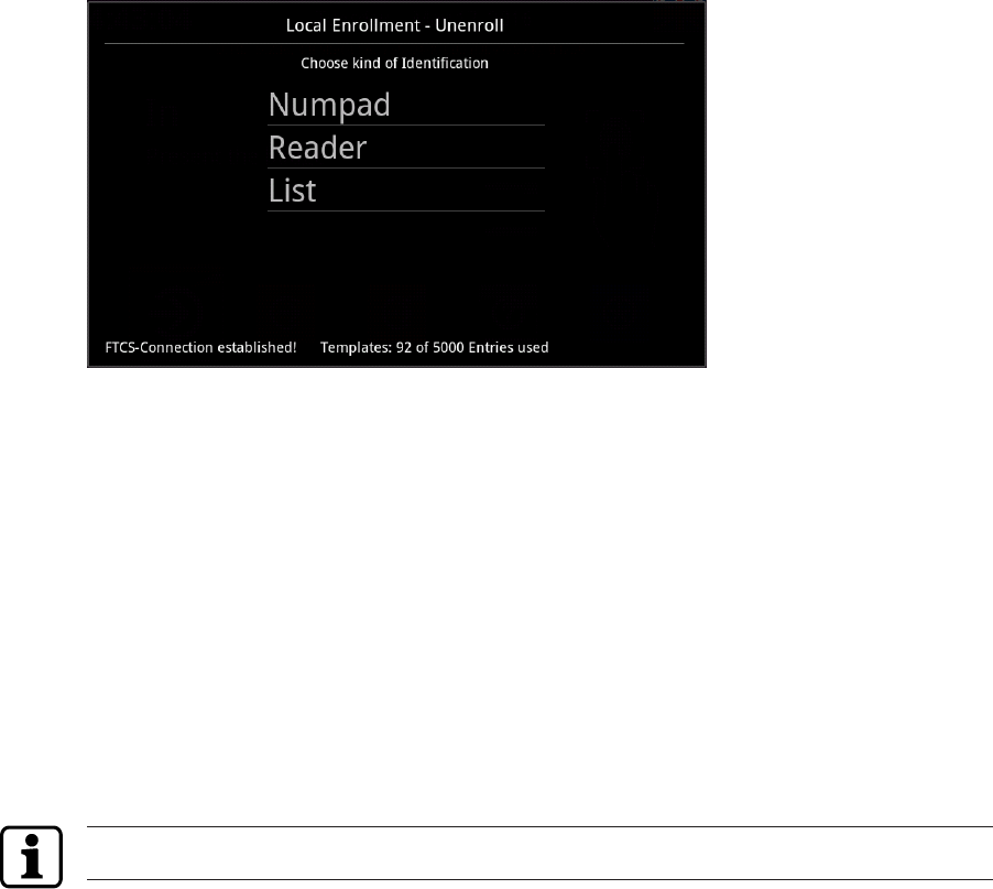
OperationTechnical Manual
9104043552 - 05/2017 Terminal 97 00DRAFT
7.10.4.3 Unenroll
This function allows individual finger templates to be deleted from the reader database in
standalone mode.
The selection of the finger template to be deleted can take place in one of the following ways.
•Numpad
The template ID is entered on the virtual keypad.
•Reader
The finger whose template is to be deleted must be placed on the reader.
•List
The template ID is selected from a list.
7.10.4.4 Identification
This function allows identification of an individual. After calling the function, the finger has to
be placed on the reader window. The associated ID is shown on the display.
7.10.4.5 List
This function lists all template IDs stored in the database.
The function is only available if the database contains fewer than 100 template IDs.
After selecting an ID, it can also be deleted by pressing 'Unenroll’.
7.10.4.6 Erase DB
This function allows all finger templates to be erased from the local database of the reader.
For safety reasons, you are prompted for a code. The Erase PIN is always '439235'.
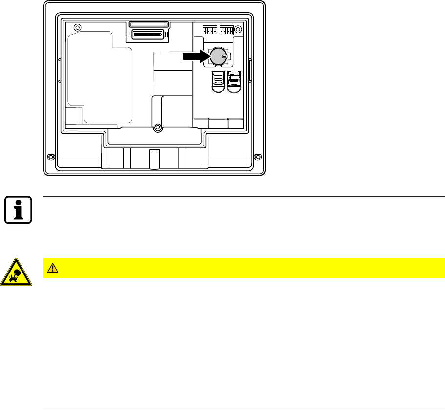
Maintenance Technical Manual
92 04043552 - 05/2017Terminal 97 00 DRAFT
8 Maintenance
8.1 Backup battery
To back up the real-time clock RTC, the device is equipped with a lithium manganese dioxide
battery type CR2032.
The battery is located on the rear side of the terminal housing.
The backup battery must be replaced with a new one every 10years.
8.1.1 Battery change
CAUTION
Lithium batteries can explode or burst explosively.
Improper handling of lithium batteries may result in fires and explosions.
• Replace lithium batteries only with batteries of the same type.
• Do not open, drill through or squash lithium batteries.
• Do not burn lithium batteries or expose them to high temperatures.
• Do not short-circuit lithium batteries.
• Do not recharge lithium batteries.
1. Remove the terminal housing from the docking station.
2. Remove UPS510 [}5.5] (if present)
3. NOTE: Do not use tools such as a screwdriver and the like.
Remove the old backup battery carefully by hand from the battery holder.
4. Push the new battery into the holder until it snaps into place.
5. Mount UPS510 (if present) again.
6. Fasten the terminal housing again to the docking station.
7. Reset terminal time.
MaintenanceTechnical Manual
9304043552 - 05/2017 Terminal 97 00DRAFT
8.2 Replacement of the uninterruptible power supply UPS510
To guarantee the buffer time as specified in the technical data, the uninterruptible power
supply UPS510 has to be replaced every 3years with a new one.
Perform dismounting and mounting of the uninterruptible power supply UPS510 as described
[}5.5].
8.3 Cleaning the housing
To clean the housing, use a soft, lint-free cloth and a mild window cleaning agent!
NOTICE
Other agents may result in damage to the housing.
Observe the following instructions in order to avoid producing damage to the housing and the
reader window of the biometric reader (if present) during the cleaning process:
• Do not use alcohol, such as ethanol and isopropanol
• Do not use aggressive solvents
• Do not use cleaning agents with added powder
• Avoid scratching and abrasive movements
Maintenance Technical Manual
94 04043552 - 05/2017Terminal 97 00 DRAFT
8.4 Installation/Update of the terminal software
For the installation or update of the terminal software on the terminal, an installation tool is
available. This so-called SFTP installer can be downloaded for the particular terminal soft-
ware in the secured area of the dormakaba website (Extranet).
Installation
For initial installation or in order to replace a faulty installation, a complete installation of the
terminal software is required.
The installation process will reset any settings already made.
Update
An update is performed in order to update the already existing terminal software to a new
version.
During an update process, only the program files will be replaced. Existing settings are re-
tained.
8.4.1 Data backup
Before an update or a new installation of the terminal software is made, the following data
must be backed up.
• Device configuration and parametrization
• If specific layout adjustments are made, the 'interface.ini’ file and pictures must be
backed up on a local drive.
8.4.2 Preparing installation/update
üAuthorization for access to dormakaba Extranet [}1.5].
1. Download SFTP installer from dormakaba Extranet.
2. Unzip ZIP file to a local directory.
3. If the SSH key for SFTP access was changed:
Copy relevant key file (*.ppk) to the directory of the SFTP installer.
In the 'Standard_Software.ini' file, enter the file name of the key file under 'Key_Path='.
Format Key_Path='<File name>.ppk'
4. Start the installation tool by double-clicking 'SFTP Installer.exe'.
ðThe first prompt of the user guidance is displayed.
8.4.3 Performing an update
1. Select the device type.
2. Select 'Update’.
3. Select terminal software (B-Client HR30)
4. Select add-ons (BaseApp + test program)
5. Enter IP address and SFTP access data.
ðA summary of the installation data is displayed.
6. Start process.
ðThe process can take several minutes. Successful execution is confirmed by the install-
ation tool.
7. Restart the device.
ðThe terminal software is now up-to-date.
MaintenanceTechnical Manual
9504043552 - 05/2017 Terminal 97 00DRAFT
8.4.4 Performing the installation
1. Select the device type.
2. Select 'Installation’
3. Select terminal software (B-Client HR30)
4. Select add-ons (BaseApp + test program)
5. Enter IP address and SFTP access data.
ðA summary of the installation data is displayed.
6. Start process.
ðThe process can take several minutes. Successful execution is confirmed by the install-
ation tool.
7. Restart the device.
8. Start-up of the device:
Perform host configuration, adjust reader settings in accordance with device configura-
tion, and transfer parameter and master records to the device.
8.5 Android update
If an update of the operating system is required, it will be provided by the dormakaba Support
in the form of the 'update.zip’ file.
The 'update.zip’ file is copied to the directory/cache of the terminal via SFTP.
The directory is interrogated by the system once a minute. If the file is detected, the operating
system is updated automatically and then the terminal is restarted.
Packaging/Returns Technical Manual
96 04043552 - 05/2017Terminal 97 00 DRAFT
9 Packaging/Returns
Components and devices that are not correctly packaged could be damaged during transport
and result in costs.
When sending dormakaba products, please observe the following notes.
Dormakaba is not liable for damage to products caused by inadequate packaging.
9.1 Complete devices
The original packaging is specially designed for the device. It offers the best possible protec-
tion against damage during transport.
When returning goods, always use the original packaging!
If this is not possible, please use packaging that prevents the device from being damaged.
• Use a sturdy, thick-walled transport box or a cardboard box. The transport box should be
large enough that there is 8–10cm space between the device and the edge of the con-
tainer.
• Wrap the device in suitable material or put it in a bag.
• Put generous padding around the device, e.g. foam padding or air cushions. The device
must not be able to move around within the packaging.
• Only use dust-free, environmentally-friendly packaging material.
9.2 Electronic components
ESD-sensitive electronic components such as printed circuit boards, readers etc. are to be
stored, transported and shipped in suitable ESD protective packaging. Electronic components
must only be packaged at ESD-proof work stations and carried out by people who are famil-
iar with and apply the general ESD protective regulations.
Electronic components must be returned in packaging with sufficient ESD protection in order
to
• make warranty claims in the event of malfunctions of any kind.
• Replacement of electronic printed circuit boards and components in the replacement pro-
cedure.
To ensure high quality standards, electronic components delivered in packaging without suffi-
cient ESD protection will neither be analysed nor repaired, but rather forwarded on directly
for disposal.
Packaging/ReturnsTechnical Manual
9704043552 - 05/2017 Terminal 97 00DRAFT
9.3 Labelling
Including all returns paperwork and labelling the package correctly enables us to process your
case quickly. Please ensure that a delivery note is enclosed in each package. The delivery note
should contain the following information:
• Number of devices or components in each package.
• Item numbers, serial numbers, designations.
• Address of your company/contact person.
• Reason for return, e.g. repair exchange.
• Accurate description of fault.
In the event of returns from outside of the EU, a customs invoice with the real customs value
and customs tariff no. will also be required.
Disposal Technical Manual
98 04043552 - 05/2017Terminal 97 00 DRAFT
10 Disposal
This product complies with the WEEE directive and is, according to DIN EN standard 50419,
marked with the WEEE symbol 'crossed-out wheeled bin’.
The symbol refers to separate disposal of electric and electronic devices in EU countries.
According to the European WEEE directive, the device must not be disposed of together with
domestic waste.
The components of the device must be separately recycled or disposed of. Used devices con-
tain valuable materials that must be recycled. Poisonous and dangerous components can
cause lasting damage to the environment if disposed of improperly.
According to the German Electrical and Electronic Equipment Act (ElektroG), the system op-
erator has the duty to return electrical and electronic equipment at the end of their lifetime
free-of-charge to the manufacturer, point of sale or public collection points established for
this purpose.
Disposal in Germany:
At the end of use of the goods supplied, Kaba GmbH will take them back for a proper disposal
in accordance with the legal regulations (German Electrical and Electronic Equipment Act,
ElektroG). Charges incurred for transport to the manufacturer will be at the expense of the
owner of the waste electrical equipment.
Disposal in Switzerland:
The equipment must be returned to an electrical equipment collection point according to
VREG.
In the EU, electrical and electronic equipment has to be disposed of according to national dis-
posal and environmental legislation.
Deletion of person-related data
Individuals are responsible for the deletion of their personal data.
Dispose of packaging in accordance with environmental regulations.
The packaging materials can be recycled. Please do not dispose of the packaging with house-
hold waste, instead send them for recycling.
Lithium batteries
To back up the real-time clock RTC, the device is equipped with a lithium manganese dioxide
battery type CR2032.
The battery is located on the rear side of the terminal housing.
Remove battery before returning the device [}8.1].
Do not dispose of the batteries in your domestic waste.
Used lithium batteries must be returned to a disposal system according to national and local
regulations.
To prevent short circuits and the resulting heating, lithium batteries must not be stored or
transported unprotected. Examples of suitable measures against short circuits include:
• Placing the battery in a plastic bag
• Covering poles with adhesive tape
See also safety instructions in Handling of lithium batteries [}2.6].
Uninterruptible power supply UPS510
The device is optionally equipped with the uninterruptible power supply UPS510.
The UPS510 contains an NiMH rechargeable battery.
Remove UPS before returning the device [}5.5].
DisposalTechnical Manual
9904043552 - 05/2017 Terminal 97 00DRAFT
Do not dispose of the UPS in your domestic waste!
The UPS must be disposed of according to state and local regulations.
Index Technical Manual
100 04043552 - 05/2017Terminal 97 00 DRAFT
Index
Numerical
24 V DC power supply 17, 47
A
Ambient conditions 17
Ambient temperature 17
Android 15
Android navigation keys 74
Android system settings 62
Android update 95
App management 82
Audio 15
Audio line-out 25
Authentication types 37
Authorizations 35
Automatic registration via B-COMM 54
B
Back 74
BaseApp 32, 81
Basic safety information 11
B-Client HR30 32
B-COMM 36
BEX120 motherboard 29, 45
BEX121 motherboard 29, 47
BEX122 motherboard 29
Biometric reader 16, 75
Biometric software 36
Browser start 34
C
Cable entry 42
Camera 15, 24
Cancelling automatic registration 54
Card slot 15, 25
CardLink 33, 39
CE conformity 21
Cleaning the housing 93
Communication principle 35
Conformity 21
Connecting an external reader 50
Connecting the mains voltage 45
Connections 45
Contact loading capacity 16, 49
CPU unit 15
CR2032 lithium battery 25
D
Data encryption 33
Deleting finger templates 91
Device structure 23
Digital inputs 16, 48
Dimensional drawings 18
Dimensions 18
Display 15
Display brightness 66
Disposal 98
Docking station 26
Door control 33
E
EEPROMsetting 72
ElektroG 98
Enroll 89
ESD protective measures 13
Ethernet connection 25, 45
Ethernet interface 16
External reader 50
F
Fastening material 44
Fastening the docking station 44
Finger position 75
Flash 24
Flush-mounted housing 20
FTCS 36
G
Ground wire 47
GSM 16
Guard time 58
H
Home 74
HSPE module 16
I
Identification 37
IndexTechnical Manual
10104043552 - 05/2017 Terminal 97 00DRAFT
IEEE 802.1x 65
Info functions 87
Ingress protection 17
Ingress protection according to IEC 60529 42
Inputs 16, 48
Installation lines 43
Installation of the terminal software 94
Interfaces 16
K
Kaba test program 56
L
Language for service texts 56
License file 32
Lithium battery 25
Local Enrollment 88
LocalEnrollment 33
Loudspeaker 15
M
MAC address 87
Mains fuses 46
Mains input fuse 46
Mains voltage input 17
Manual settings 55
Marking 22
Memory 15
Memory options 33
Menu 74
Microphone 15
microSD card 25
Mobile radio 16
Mounting height 40
Mounting plate 44
MRD reader 57
Multimedia 15
N
Native apps 34
Navigation bar 74
Navigation keys 74
Network cable 43
Network connection 45
Network requirements 53
Network settings 63
O
Operating elements 73
Operating states 36
Operating system 15
Operating system update 95
Outputs 16
P
Packaging 96
Parametrization 35
Partner application 34
Power over Ethernet 17
Power supply 17
Proper use 11
Protective conductor 45
Protective housing 19
Proximity sensor 15, 24
R
Rating plate 22
Reader 16
Reader type 57
Real-time clock RTC 92
reboot.cmd 72
Registering fingerprints 89
Registering new fingerprints at the terminal 88
Relative humidity 17
Relay outputs 16, 49
Remote setup 72
Replacement terminal 34
Replacing the backup battery 92
Returns 96
RFID reader 16, 75
RoHS 21
RS-232 16, 50
RTC 15
S
Safety 11
Safety information 11
Search 74
Service language 56
SFTP server 69
SIM card 25
sop.ini 32
SSH key 70
Starting B-Client HR30 85
Starting the application 81
Sun irradiation 40
Supplementary documentation 8
Surface-mounted protective metal housing 19
Index Technical Manual
102 04043552 - 05/2017Terminal 97 00 DRAFT
Swipe reader 76
Symbols 74
System 15
System connection 35
T
Terminal housing 24
Terminal software update 94
Test program 32, 56
Time and attendance 32
Touch screen 15
U
UMTS 16
Unenroll 91
Uninterruptible power supply 17, 51
Update of the terminal software 94
update.zip 95
UPS510 17, 51
USB 16
USB port 25
User interface 81
V
Verification 37
Volume setting 66
W
Washer 44
WEEE Directive 98
WLAN 16