dormakaba EAD KAM9230-K5 RFID Reader User Manual TM 9230 K5 201605 en
Kaba GmbH RFID Reader TM 9230 K5 201605 en
UserManual.wiki
>
dormakaba EAD
>
KAM9230 K5 User Manual
user manual
Navigation menu
Upload a User Manual
Namespaces
Wiki Guide
HTML
PDF
Info
Views
User Manual
Discussion / Help
Navigation
![About this Document Technical Manual8 04045376 - 05/2016 Kaba access manager 92 301.4 Orientation in the documentThis document contains the following orientation aids to facilitate finding of specifictopics:• The table of contents at the beginning of the manual gives an overview of alltopics.• The header always contains the respective main chapter.• Cross references always indicate the number of the chapter in which the supple-mentary information can be found. Example [ 5.7].• An index in the alphabetical order is given at the end of the manual.1.5 Additional documentationDetails on setting specific device parameters can be found in the reference manual ofthe terminal software used.Supplementary documentation is available on the Kaba website. The technical man-uals are located in a secured area of the website.• Access is only possible after logging in.• An account will need to be created before logging in for the first time.Access and login:1. In the browser, access the Kaba page http://www.kaba.com.2. Select the language in the top right.3. Under "Products", select the "Access Management" or "Workforce Management"product division.4. In the top right section of the screen, click on the following symbol:.5. Enter your e-mail address and password and login or create an account (see be-low).ðThe technical manuals can be found under "Downloads".Create account:1. Click "Create account".2. Complete the data fields and confirm.ðA confirmation link will be sent to your e-mail address.3. To activate your account, click on the confirmation link in your e-mail.](https://usermanual.wiki/dormakaba-EAD/KAM9230-K5/User-Guide-3343772-Page-8.png)
![Technical Manual Product Description2104045376 - 05/2016Kaba access manager 92 303.5 ConformityThis product conforms to the following standards:EN 60950-1:2006 + A11:2009 + A1:2010 + A12:2011EN 300 330-1 V1.7.1EN 300 330-2 V1.5.1EN 301 489-1 V1.9.2EN 301 489-3 V1.6.1EN 55022:2010, Class BEN 55024:2010according to the regulations of the EC Directive1999/5/EC R&TTE DirectiveThe original Declaration of Conformity can be downloaded from www.kaba.com/conformity in PDF format.In addition, the product also conforms to the following standards:UL 60950-1UL 294, security performance level 1 RoHS This device complies with the regulations of the Directive 2011/65/EU of the Euro-pean Parliament and of the Council of June 8, 2011, on the restriction of the use ofcertain hazardous substances in electrical and electronic equipment.FCC FCC Code of Federal Regulations, CFR 47, Part 15, Sections 15.205, 15.207,15.215 and 15.225FCC ID NVI-KAM9230-K5FCC § 15.19This device complies with Part 15 of the FCC rules. Operation is subject to the follow-ing two conditions: (1) This device may not cause harmful interference, and (2) thisdevice must accept any interference received, including interference that may causeundesired operation.FCC § 15.21 (Warning Statement)[Any] changes or modifications not expressly approved by the party responsible forcompliance could void the user’s authority to operate the equipment.FCC § 15.105Note: This equipment has been tested and found to comply with the limits for a ClassA digital device, pursuant to part 15 of the FCC Rules.These limits are designed to provide reasonable protection against harmful interfer-ence when the equipment is operated in a commercial environment. This equipmentgenerates, uses, and can radiate radio frequency energy and, if not installed and usedin accordance with the instruction manual, may cause harmful interference to radiocommunications. Operation of this equipment in a residential area is likely to causeharmful interference in which case the user will be required to correct the interfer-ence at his own expense.](https://usermanual.wiki/dormakaba-EAD/KAM9230-K5/User-Guide-3343772-Page-21.png)
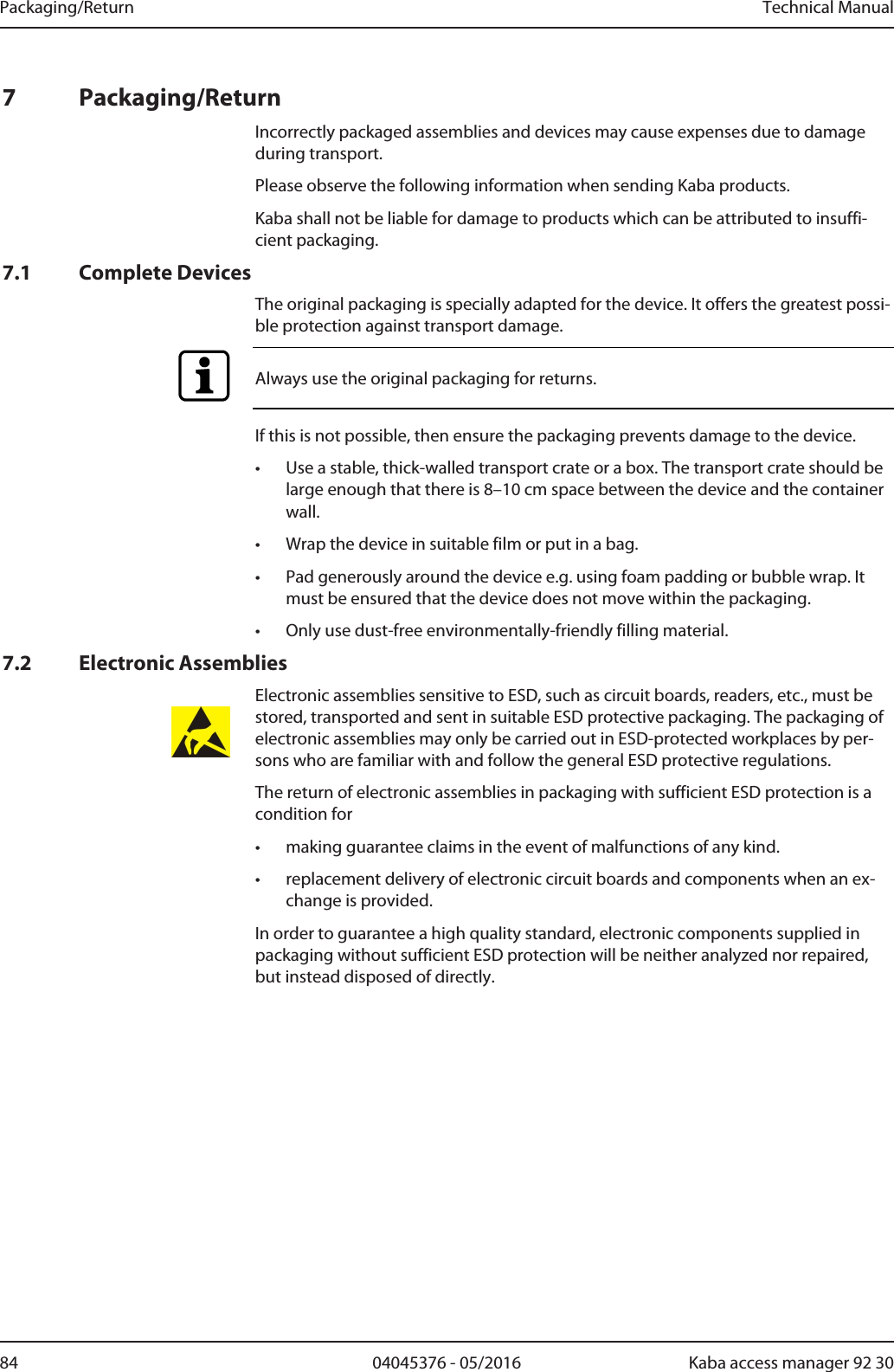
![Technical Manual Installation4704045376 - 05/2016Kaba access manager 92 305.7.3 External 24 V DC power supplyAs an alternative to the PoE power supply, the access manager can also be suppliedvia an external 24 V DC power supply unit.The connection of the external power supply is performed at terminal 24 V EXT.The PoE switch [}5.6] must be set to "PoE+" position in this case.Use only power supply units that fulfill the requirements of EN60950-1 as limitedpower source.](https://usermanual.wiki/dormakaba-EAD/KAM9230-K5/User-Guide-3343772-Page-47.png)
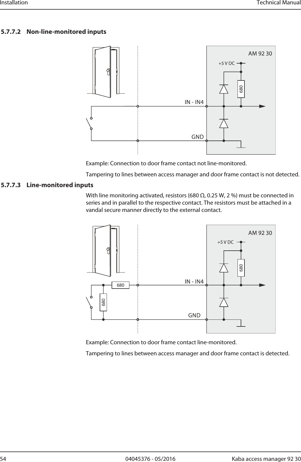
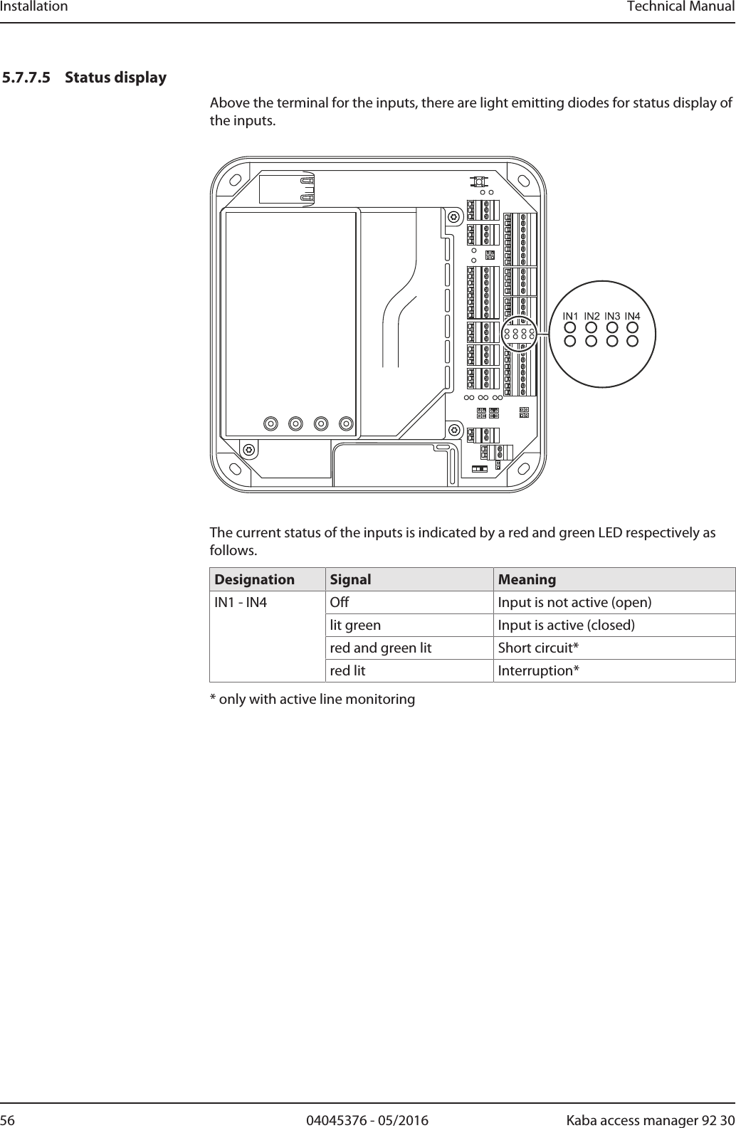
![Technical Manual Installation5304045376 - 05/2016Kaba access manager 92 305.7.7 InputsThe access manager has 4 inputs IN1 to IN4.Function of the inputsThe inputs are used for the inquiry of sensors such as door-opener key, door handlecontact, door frame contact, bolt contact, vandal contact, pass-through contact (e.g.,turnstile, light barrier), etc.The function of the individual outputs depends on the settings of the terminal soft-ware.PrincipleThe inputs (IN1-IN4) are connected to GND using a simple switch or relay contact. Anopen input is recognized as “high” due to the internal pull-up resistor. Ground poten-tial equals “low.”5.7.7.1 Line monitoringThe inputs can be designed as follows:• Without line monitoring• With line monitoring (if supported and activated by the terminal software)Line monitoring allows the terminal software to detect the states short circuit and in-terruption, in addition to the states active (input closed) and not active (input open)and report them to the higher-level system.The current states of the inputs are signaled by light emitting diodes [}5.7.7.5].](https://usermanual.wiki/dormakaba-EAD/KAM9230-K5/User-Guide-3343772-Page-53.png)
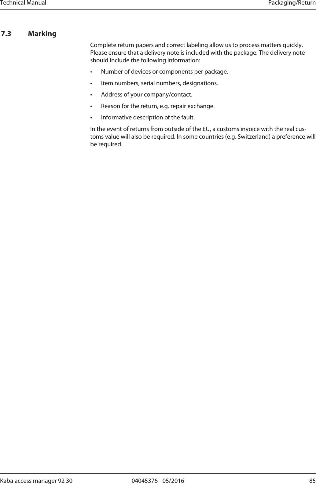
![Installation Technical Manual64 04045376 - 05/2016 Kaba access manager 92 305.7.9 Standard assignment of inputs/outputs (B-Client AC30)The following assignment for the inputs and outputs has been preset for the B-Client AC30 terminal software [}5.7.10.3].The assignment of the functions can be adjusted in the b_client_ac30.ini configura-tion file. Details on the configuration can be found in the B-Client AC30 referencemanual.5.7.9.1 InputsThe following functions are assigned by default to the inputs by the terminal soft-ware.Input Connection FunctionBI01 IN1 Door frame contact 1BI02 IN2 Door-opener key 1BI03 IN3 Door frame contact 2BI04 IN4 Door-opener key 2BI36 IN5 Vandal contact5.7.9.2 OutputsThe following functions are assigned by default to the outputs by the terminal soft-ware.Output Connection FunctionBO01 OUT1 Door opener relay Door 1BO02 OUT2 Door opener relay Door 2BO20 OUT3 General alarm](https://usermanual.wiki/dormakaba-EAD/KAM9230-K5/User-Guide-3343772-Page-64.png)
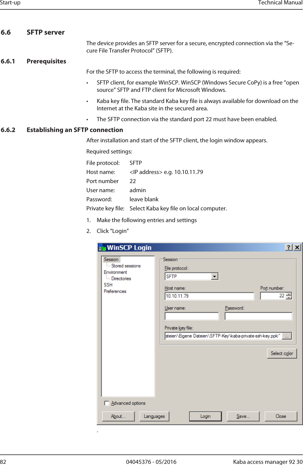
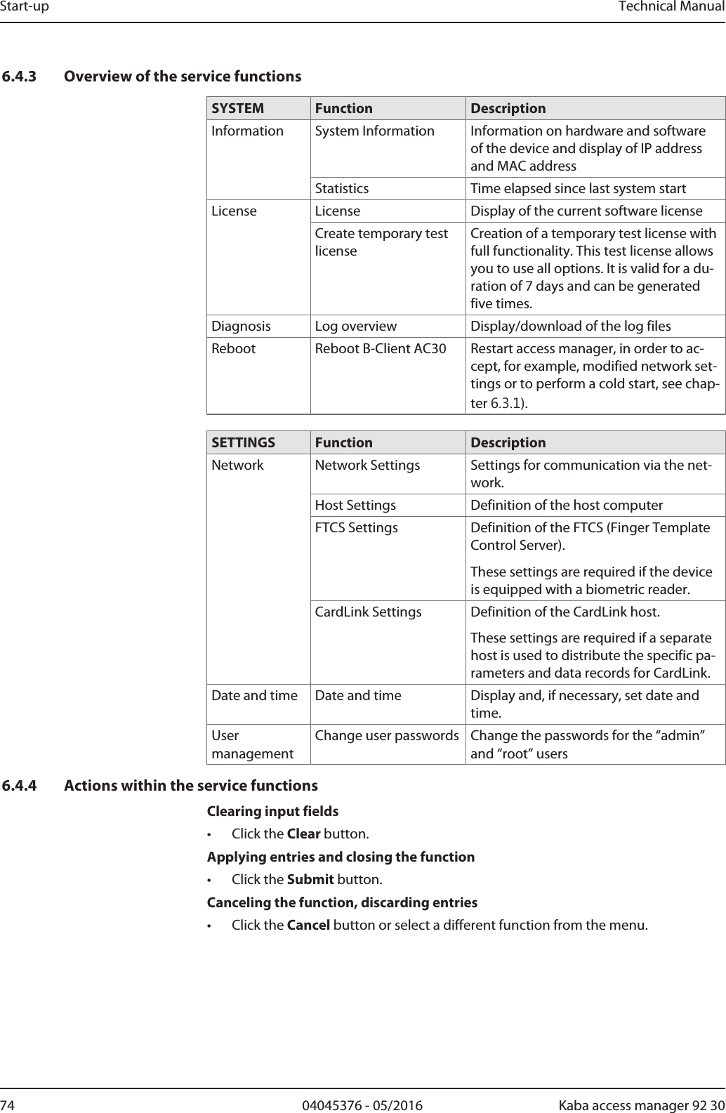
![Technical Manual Start-up7304045376 - 05/2016Kaba access manager 92 306.4 Service InterfaceThe device is provided with a service interface allowing you to make manual settings.Access takes place via the network connection of the device, either directly or via thenetwork. For direct connection, an Ethernet cross-over cable (crossed RJ-45 cable) oran Ethernet patch cable 1:1 can be used (Auto MDIX).The service interface can be accessed from a service PC via web browser by typingthe device IP address into the address box. If the IP address of the device is notknown, you can either set the default IP address 123.0.0.2 or determine and assignthe IP address using the Device Discovery Tool [}6.5].The Device Discovery Tool is always available for download on the Internet at theKaba site.6.4.1 LoginUser name and password are requested after selecting the service interface.The following users are already defined by default:User name Passwordadmin adminroot root6.4.1.1 Changing passwordsFor security reasons, the default password should be changed. After the login withuser "root", both passwords can be changed by means of the "User management"function.6.4.2 Basic structureAfter successful login, you can use the service functions. Select the desired functionfrom the main menu on the left.](https://usermanual.wiki/dormakaba-EAD/KAM9230-K5/User-Guide-3343772-Page-73.png)
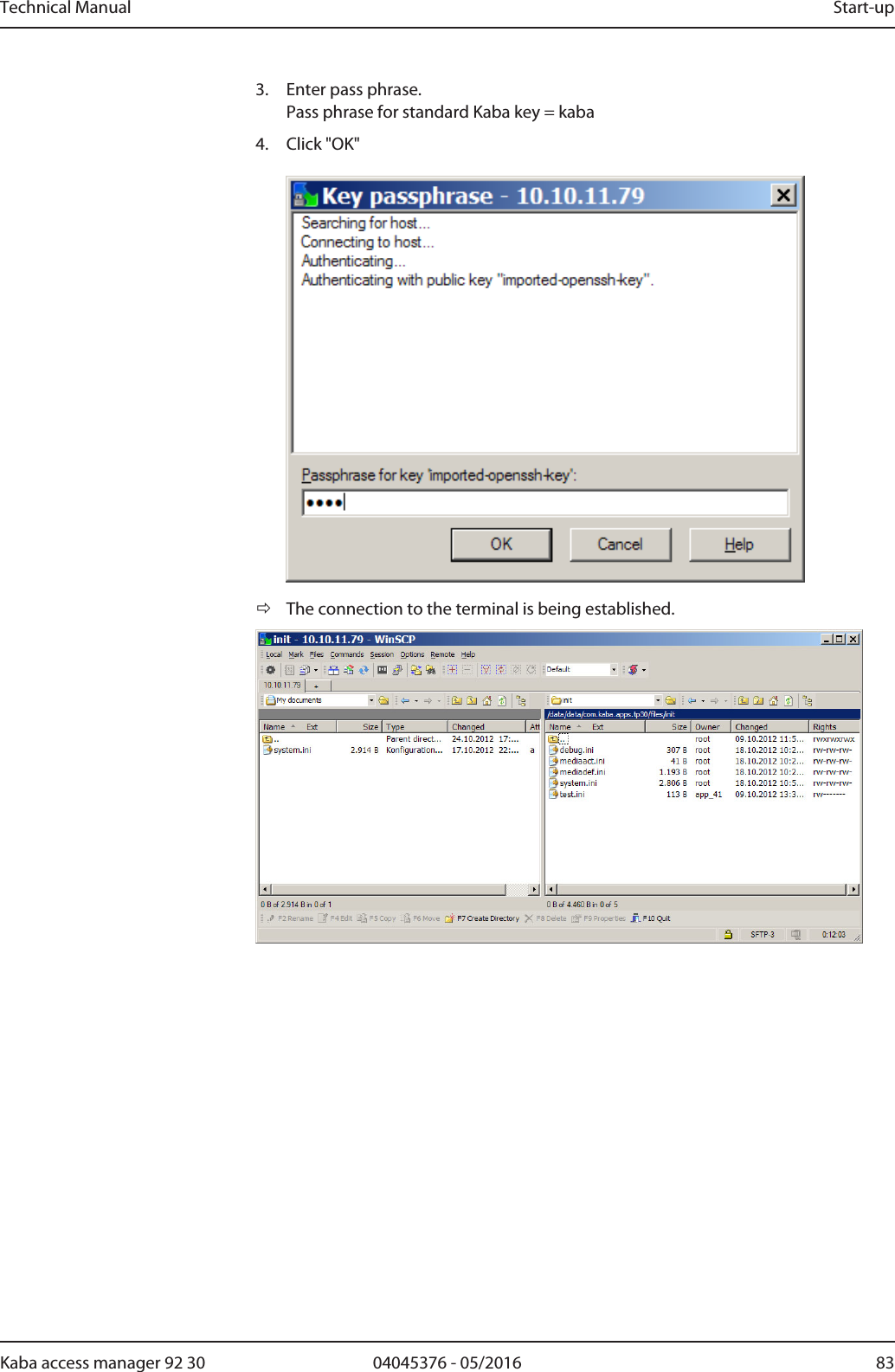
![Technical Manual Start-up7704045376 - 05/2016Kaba access manager 92 306.4.6 Host settingsSetting of the communication type and definition of the host computer.Function call: Menu > SETTINGS > Network > Host SettingsCommunication via Ethernet / UDPThis is the standard communication type1. Set the “ETH/UDP” interface.2. Enter the IP address of the computer communicating with the terminal softwarein the “Host name or IP address” field. If a DNS has been configured, it is also pos-sible to specify the host name in this field.3. In the “Port” field, select the UDP port used for communication. It is specified inhexadecimal format. Possible values are 7700 to 77EF.Communication via Ethernet / XMLThis communication type is a precondition for HTTP/HTTPS-based applications thatare used directly as communication software instead of B-COMM.1. Set the "ETH/XML" interface.2. Enter the IP address of the computer communicating with the terminal softwarein the “Host name or IP address” field. If a DNS has been configured, it is also pos-sible to specify the host name in this field.3. In the “Port” field, select the UDP port used for communication. It is specified inhexadecimal format. Possible values are 7700 to 77EF.Automatic registrationThis function allows the device to be operated almost automatically. The device re-ports cyclically to the active B-COMMs in the network and is then registered [}6.2]by them.The function can be enabled or disabled by means of the "Host Registration" checkbox.](https://usermanual.wiki/dormakaba-EAD/KAM9230-K5/User-Guide-3343772-Page-77.png)