dormakaba EAD KAM9230-K5 RFID Reader User Manual TM 9230 K5 201605 en
Kaba GmbH RFID Reader TM 9230 K5 201605 en
user manual
Kaba access manager 92 30
Technical Manual
EN
04045376 - 05/2016

Kaba AG
Access & Workforce Management
Hofwisenstrasse 24
8153 Rümlang
Switzerland
Phone +41 44 818 93 11
www.kaba.com
Kaba AG
Access & Workforce Management
Mühlebühlstrasse 23
8620 Wetzikon
Switzerland
Phone +41 44 931 61 11
www.kaba.com
Kaba GmbH
Access & Workforce Management
Albertistraße 3
78056 Villingen-Schwenningen
Germany
Phone +49 7720 603 0
www.kaba.com
This document must not be reproduced in any way or otherwise further used without the written consent of Kaba AG.
All product names are trademarks of the respective companies.
Copyright 2016 Kaba AG. All rights reserved.
04045376 - 05/2016

Technical Manual Table of Contents
Kaba access manager 92 30 304045376 - 05/2016
Table of Contents
1 About this Document ............................................................................................................................. 7
1.1 Validity............................................................................................................................................................................... 7
1.2 Target group ................................................................................................................................................................... 7
1.3 Contents and purpose................................................................................................................................................. 7
1.4 Orientation in the document.................................................................................................................................... 8
1.5 Additional documentation ........................................................................................................................................ 8
1.6 Warnings........................................................................................................................................................................... 9
1.6.1 Hazard Categories.......................................................................................................................................... 9
1.6.2 Symbols.............................................................................................................................................................. 9
1.7 Notes.................................................................................................................................................................................. 9
2 Grouped safety messages.................................................................................................................... 10
2.1 Use as directed .............................................................................................................................................................10
2.2 Mounting and installation........................................................................................................................................10
2.3 Service and Maintenance .........................................................................................................................................10
2.4 Accessories and spare parts ....................................................................................................................................10
2.5 ESD (electrostatic discharge) protective measures.........................................................................................11
2.6 Environmental protection .......................................................................................................................................11
3 Product Description ............................................................................................................................. 12
3.1 Overview.........................................................................................................................................................................12
3.2 Device variants .............................................................................................................................................................13
3.3 B-Client AC30 terminal software............................................................................................................................14
3.3.1 Areas of application.....................................................................................................................................14
3.3.2 Software options ..........................................................................................................................................14
3.3.3 Supported readers/subterminals ...........................................................................................................15
3.3.4 Readers via Wiegand...................................................................................................................................15
3.3.5 Registration units .........................................................................................................................................16
3.4 Technical Data ..............................................................................................................................................................17
3.4.1 Power supply .................................................................................................................................................17
3.4.2 Output voltages............................................................................................................................................17
3.4.3 Outputs ............................................................................................................................................................18
3.4.4 Inputs................................................................................................................................................................18
3.4.5 Interfaces .........................................................................................................................................................19
3.4.6 Reader...............................................................................................................................................................19
3.4.7 Ambient conditions.....................................................................................................................................20
3.4.8 Dimensions/Weight.....................................................................................................................................20
3.4.9 Dimensional drawings................................................................................................................................20
3.5 Conformity.....................................................................................................................................................................21
3.6 Labeling ..........................................................................................................................................................................22
4 Design and function ............................................................................................................................. 23
4.1 Opening the housing.................................................................................................................................................23
4.2 Functional principle....................................................................................................................................................24
4.2.1 Typical applications.....................................................................................................................................25
4.2.2 Superior system ............................................................................................................................................26
4.2.3 Reader...............................................................................................................................................................26
4.2.4 Function of the inputs ................................................................................................................................27

Table of Contents Technical Manual
4 Kaba access manager 92 3004045376 - 05/2016
4.2.5 Function of the outputs .............................................................................................................................27
4.3 Access control with B-Client AC30........................................................................................................................28
4.3.1 Operating states ...........................................................................................................................................28
4.3.2 Sequence of authorization checks.........................................................................................................30
4.3.3 Examples of door surveillance time sequences ................................................................................31
4.4 Light emitting diodes ................................................................................................................................................34
4.4.1 Device status..................................................................................................................................................35
5 Installation ............................................................................................................................................ 36
5.1 Installation conditions...............................................................................................................................................36
5.1.1 General.............................................................................................................................................................36
5.1.2 Installation site ..............................................................................................................................................36
5.1.3 Connections ...................................................................................................................................................36
5.1.4 Cable entry......................................................................................................................................................37
5.2 Installation diagram ...................................................................................................................................................38
5.2.1 Access control with registration unit ....................................................................................................38
5.2.2 Access control with reader via RS-485..................................................................................................39
5.2.3 Access control with readers via Wiegand............................................................................................40
5.3 Installation lines...........................................................................................................................................................41
5.3.1 Ethernet ...........................................................................................................................................................41
5.3.2 Power supply of the reader.......................................................................................................................41
5.3.3 Data line to reader/subterminal..............................................................................................................41
5.3.4 Line to the door opener, the door opener key, and the door contacts....................................41
5.3.5 Coaxial cables to registration units........................................................................................................41
5.3.6 Line to the Wiegand reader......................................................................................................................41
5.4 Wall mounting..............................................................................................................................................................42
5.5 Cable routing ................................................................................................................................................................43
5.6 Setting the PoE switches ..........................................................................................................................................44
5.7 Connections ..................................................................................................................................................................45
5.7.1 Network connection....................................................................................................................................45
5.7.2 Overview of terminals.................................................................................................................................46
5.7.3 External 24 V DC power supply ...............................................................................................................47
5.7.4 Registration units .........................................................................................................................................48
5.7.5 Readers via RS-485.......................................................................................................................................49
5.7.6 Readers via Wiegand...................................................................................................................................52
5.7.7 Inputs................................................................................................................................................................53
5.7.8 Outputs ............................................................................................................................................................57
5.7.9 Standard assignment of inputs/outputs (B-Client AC30) ..............................................................64
5.7.10 Configuration-dependent assignment (B-Client AC30).................................................................65
5.8 Vandal contact..............................................................................................................................................................67
5.9 Fastening the cover....................................................................................................................................................68
6 Start-up ................................................................................................................................................. 69
6.1 Network requirements ..............................................................................................................................................69
6.1.1 Communication ............................................................................................................................................69
6.1.2 Automatic registration via B-COMM .....................................................................................................69
6.2 Automatic registration via B-COMM ....................................................................................................................70
6.3 Start options..................................................................................................................................................................71
6.3.1 Performing a cold start...............................................................................................................................71
6.3.2 Perform a cold start and set the default IP address 123.0.0.2 ......................................................72
6.3.3 Setting the default IP address 123.0.0.2 (without cold start)........................................................72
6.4 Service Interface ..........................................................................................................................................................73

Technical Manual Table of Contents
Kaba access manager 92 30 504045376 - 05/2016
6.4.1 Login .................................................................................................................................................................73
6.4.2 Basic structure ...............................................................................................................................................73
6.4.3 Overview of the service functions..........................................................................................................74
6.4.4 Actions within the service functions .....................................................................................................74
6.4.5 Network settings...........................................................................................................................................75
6.4.6 Host settings ..................................................................................................................................................77
6.4.7 FTCS host settings........................................................................................................................................79
6.4.8 CardLink host settings ................................................................................................................................79
6.5 Device Discovery Tool ...............................................................................................................................................80
6.5.1 System requirements..................................................................................................................................80
6.5.2 Selecting the network interface..............................................................................................................80
6.5.3 Displaying devices with B-Client AC30.................................................................................................80
6.5.4 Changing network parameters ...............................................................................................................81
6.6 SFTP server.....................................................................................................................................................................82
6.6.1 Prerequisites...................................................................................................................................................82
6.6.2 Establishing an SFTP connection............................................................................................................82
7 Packaging/Return................................................................................................................................. 84
7.1 Complete Devices .......................................................................................................................................................84
7.2 Electronic Assemblies ................................................................................................................................................84
7.3 Marking ...........................................................................................................................................................................85
8 Disposal................................................................................................................................................. 86
9 Appendix............................................................................................................................................... 87
9.1 Configuration Kaba Access Manager 92 30 .......................................................................................................87
Index...................................................................................................................................................... 88

Table of Contents Technical Manual
6 Kaba access manager 92 3004045376 - 05/2016

Technical Manual About this Document
704045376 - 05/2016Kaba access manager 92 30
1 About this Document
1.1 Validity
This document describes the product:
Product name: Kaba access manager 92 30
Item number 04079230
Terminal software: B-Client AC30 from version 669-01-X-K00
Manufacturing date: Starting from March 2016
This document describes all device versions and optional equipment and functions.
Options need to be paid for and are therefore only available if they have been pur-
chased. Additional equipment and functions may not yet be available at the time of
issuing the document and, possibly, can only be purchased at a later stage.
1.2 Target group
This document is exclusively intended for specialist personnel.
The descriptions require specialist personnel trained by the manufacturer. The de-
scriptions do not replace product training.
For reasons of device safety, the installation and maintenance operations described
in this document must be carried out only by service persons according to EN
60950-1 (Information technology equipment - Safety).
Service persons are persons having adequate technical training and sufficient experi-
ence to be aware of and to minimize the possible risks for themselves or other per-
sons, which may occur when carrying out these operations. The service persons are
responsible for adhering to the instructions given by the manufacturer and to the ap-
plicable standards and regulations during execution of their work.
This document is also used as information for persons with the following tasks:
• project planning and implementation
• Commissioning the product within the network
• Connecting the product to the user software by programming customer applica-
tions
• Customer-specific adjustment by setting the parameters of the product
1.3 Contents and purpose
The contents is limited to the assembly, installation, start-up, and basic operation of
the hardware.

About this Document Technical Manual
8 04045376 - 05/2016 Kaba access manager 92 30
1.4 Orientation in the document
This document contains the following orientation aids to facilitate finding of specific
topics:
• The table of contents at the beginning of the manual gives an overview of all
topics.
• The header always contains the respective main chapter.
• Cross references always indicate the number of the chapter in which the supple-
mentary information can be found. Example [ 5.7].
• An index in the alphabetical order is given at the end of the manual.
1.5 Additional documentation
Details on setting specific device parameters can be found in the reference manual of
the terminal software used.
Supplementary documentation is available on the Kaba website. The technical man-
uals are located in a secured area of the website.
• Access is only possible after logging in.
• An account will need to be created before logging in for the first time.
Access and login:
1. In the browser, access the Kaba page http://www.kaba.com.
2. Select the language in the top right.
3. Under "Products", select the "Access Management" or "Workforce Management"
product division.
4. In the top right section of the screen, click on the following symbol:
.
5. Enter your e-mail address and password and login or create an account (see be-
low).
ðThe technical manuals can be found under "Downloads".
Create account:
1. Click "Create account".
2. Complete the data fields and confirm.
ðA confirmation link will be sent to your e-mail address.
3. To activate your account, click on the confirmation link in your e-mail.
Technical Manual About this Document
904045376 - 05/2016Kaba access manager 92 30
1.6 Warnings
Warnings containing information/instructions and prohibitions to prevent injury to
persons and damage to property are specially labeled.
Please pay attention to warnings. They are intended to help prevent accidents and
avoid damage.
1.6.1 Hazard Categories
Warnings are split into the following categories:
CAUTION
Slight Risk
Describes a potentially hazardous situation that could result in minor physical in-
juries.
NOTICE
Information on how to handle the product correctly.
Failure to comply with these warnings may result in malfunctions. The product or
something in its vicinity could be damaged.
1.6.2 Symbols
Depending on the source of the hazard, symbols are used for the warnings, and
these have the following meanings:
General danger Danger for electronic compo-
nents from electrostatic dis-
charge
1.7 Notes
Notes are labeled with an info symbol.
Tips and useful information.
These help you to make best use of the product and its functions.

Grouped safety messages Technical Manual
10 04045376 - 05/2016 Kaba access manager 92 30
2 Grouped safety messages
This product has been built in accordance with state-of-the-art standards and the
recognized safety rules. Nevertheless, its use may constitute a risk to persons and
cause damage to material property.
Read and observe the following safety instructions before using the product.
2.1 Use as directed
The product is only intended for use as described in chapter “Product description”.
Any use beyond that is considered contrary to its designated use. The manufacturer
cannot be held liable for damage resulting from such use. Such use is at the sole risk
of the user/operator.
2.2 Mounting and installation
Mounting and installation may only be carried out by service persons (see chapter 1
“Target group”).
Mains voltage installations may only be carried out by a certified specialized com-
pany or authorized electricians.
Installation may only be carried out in places that fulfill the climatic and technical
conditions stated by the manufacturer.
The manufacturer is not liable for damages resulting from improper handling or in-
correct installation.
2.3 Service and Maintenance
Maintenance work / troubleshooting
Only the service person (see chapter 1 “Target group”) is entitled to remove faults
and carry out maintenance work.
Reconstruction and modification
Any alteration or modification to the device may only be performed by the service
person (see chapter 1 “Target group”). Any alteration or modification performed by
unauthorized persons shall render void any liability.
2.4 Accessories and spare parts
Accessories and spare parts must comply with the technical requirements specified
by the manufacturer. This is guaranteed when using original accessories and spare
parts from Kaba.

Technical Manual Grouped safety messages
1104045376 - 05/2016Kaba access manager 92 30
2.5 ESD (electrostatic discharge) protective measures
NOTICE
Danger for electronic components due to electrostatic discharge.
Improper handling of printed circuit boards or components can cause damages that
lead to complete failures or sporadic errors.
• During installation and repair of the product, the ESD protective measures must
be considered.
• Wear an ESD wristband when handling electronic components. Connect the end
of the wristband to a discharge socket or an unvarnished grounded metal com-
ponent. This way, static charges are discharged from your body securely and ef-
fectively.
• Touch only the edges of circuit boards. Do not touch the circuit board nor the
connector.
• Place all dismantled components on an antistatic surface or in an antistatic con-
tainer.
• Avoid contact between circuit boards and clothing. The wristband only protects
the printed circuit boards against electrostatic discharge from your body, but
there is still a risk of damage through electrostatic discharge from your clothing.
• Transport and dispatch dismantled modules only in electrostatically shielded
protective bags.
2.6 Environmental protection
It is prohibited to dispose of the device in your domestic waste.
Used devices contain valuable materials that should be recycled. Properly dispose of
used devices.

Product Description Technical Manual
12 04045376 - 05/2016 Kaba access manager 92 30
3 Product Description
3.1 Overview
The Kaba access manager 92 30 is designed specifically for control of an individual
door (access/exit). The access manager can also be used for the decentralized access
control applications.
This is why the device is installed in secure indoor locations near the access. The de-
vice is designed for direct mounting on the wall. However, it can also be mounted in
suspended ceilings, wall recesses etc.
Depending on the device version, the access manager supports the connection of
registration units, readers/subterminals via RS-485 or Wiegand. The registration unit
allows contact-free reading and writing of RFID media in MIFARE or LEGIC technol-
ogy (depending on the configuration).
A 10BASE-T/100BASE-TX Ethernet interface is provided for communication with the
host on the network.
Power is supplied over PoE (Power over Ethernet). As an alternative the power supply
can also be performed via an external 24 V DC power supply unit.
The device has 4 inputs and 3 outputs. They can be used for control and monitoring
of Door management.
Technical Manual Product Description
1304045376 - 05/2016Kaba access manager 92 30
3.2 Device variants
The Kaba access manager 92 30 is available in two device variants: The difference is in
the possible reader connection.
One variant allows connection of 2 RFID registration units or readers/subterminals via
RS-485. The other variant allows connection of 2 readers via Wiegand.
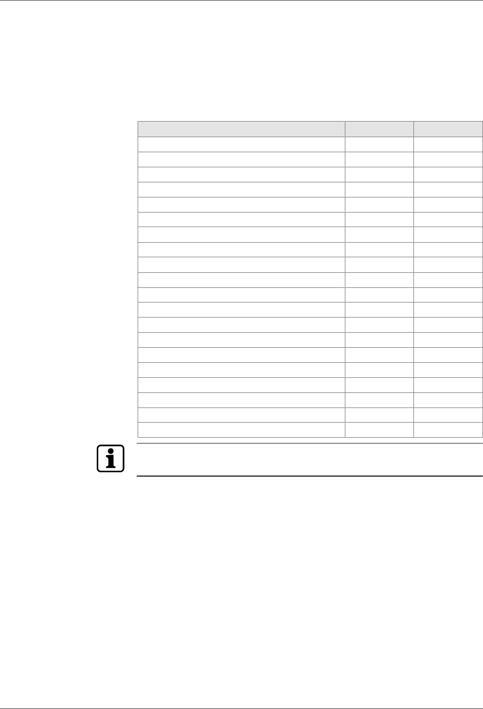
Equipment depending on the device version - Overview
Equipment / Variant RFID Wiegand
Communication
Ethernet interface X X
Connections for readers
Registration units X
Readers/subterminals via RS-485 X
Readers via Wiegand X
Serial interface
RS-232 for specific applications X X
Inputs / Outputs
4 digital inputs X X
3 relay outputs X X
Vandal contact Cover X X
Vandal contact Wall X X
Power supply
PoE (Power over Ethernet) X X
24 V DC power supply X X
Output voltages
5 V DC X
12 V DC X X
24 V DC (only for 24 V DC power supply) X X
Depending on the device variants, the corresponding terminals are available or not
available for readers.

Product Description Technical Manual
14 04045376 - 05/2016 Kaba access manager 92 30
3.3 B-Client AC30 terminal software
B-Client AC30 is a terminal software for access control. This terminal software makes
the device compatible with the data records used in previous access controls of the
B-Net series.
3.3.1 Areas of application
Access control
The access manager uses various test criteria to check whether a booking made on a
reader/subterminal is authorized or not.
Door management
• Sluice control
• Door activation
• Monitoring of door opening
• Monitoring of door opening time
• Access monitoring
Alarm Management
The access manager reports irregularities in access control or door management to
the host computer. An additional function is to activate relays.
3.3.2 Software options
Various software options can be used to expand the functional scope of the terminal
software. Software options need to be enabled in the “sop.ini” license file using a
suitable license key.
The sop.ini license file is located in the following directory:
home/admin/Program/Share/Init
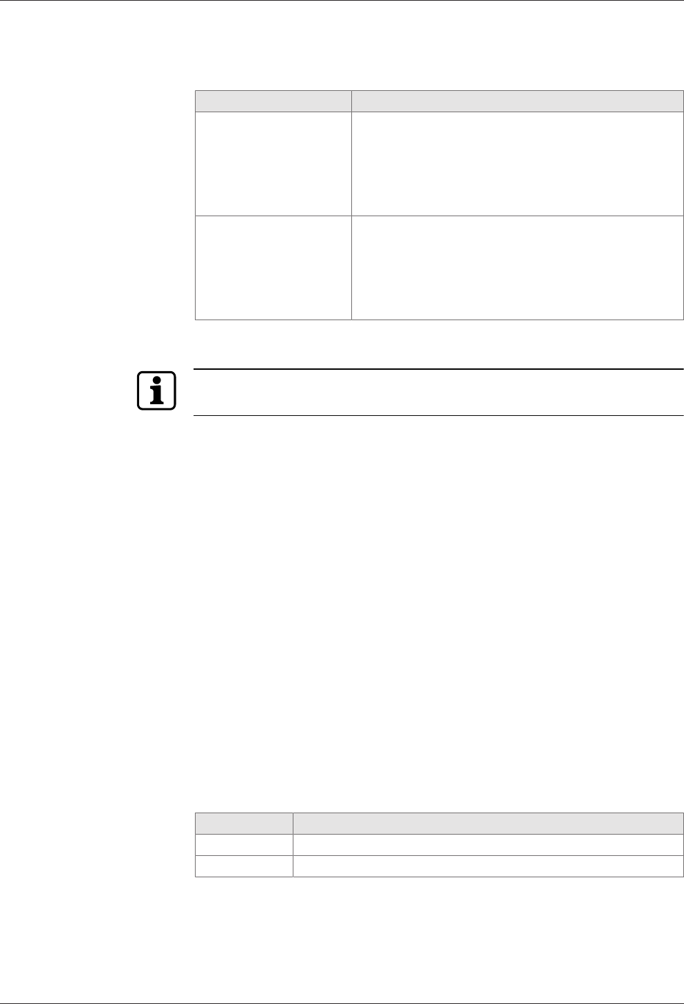
The following software options are available:
Memory options
Standard Option 1 Option 2
Master records 2,000 10,000 50,000
Registration records 8,000 40,000 100,000
CardLink update records 4,000 20,000 25,000
CardLink validation records 2,000 10,000 25,000
CardLink
CardLink validation in connection with LEGIC or MIFARE readers/subterminals.
CardLink update via registration units
AVISO
Customer-specific functional upgrades by means of AVISO routines.
Data encryption
Data encryption via Ethernet UDP in connection with the B-COMM communication
software.
Data encryption via HTTPS for XML communication.
Number of subterminals
The fixed number of supported subterminals is 2 (registration units and / or subter-
minals via RS-485 or readers via Wiegand).
Technical Manual Product Description
1504045376 - 05/2016Kaba access manager 92 30
3.3.3 Supported readers/subterminals
The access manager (RFID device variant) supports max. 2 readers/subterminals.
Subterminal Supported function
Compact reader 91 04
Compact reader 91 10
Remote reader 91 15
LEGIC mode:
Reading and writing LEGIC prime (CardLink validation)
Reading and writing LEGIC advant (CardLink validation)
MIFARE mode:
Reading and writing MIFARE DESFire/Classic (CardLink
validation)
Biometric reader 91 50 Finger template transfer via subpartyline
LEGIC mode:
Reading LEGIC prime**
Reading LEGIC advant*/**
MIFARE mode:
Reading MIFARE DESFire/Classic
* not part of standard equipment, function depends on the reader driver used.
** only devices with optional RFID reader.
The readers listed above must be equipped with the firmware of "Subterminal" func-
tion type.
Power supply of the subterminals
For power supply of subterminals connected via the RS-485 interface, the 12 V DC
output voltage of the access manager can be used.
The supply of readers/subterminals by a separate external power supply is also possi-
ble.
Inputs/Outputs of the subterminals
The inputs and outputs of the subterminals can be used, thus increasing the usable
number of inputs/outputs.
The control of the door openers by means of a relay is recommended only in secured
areas.
Time-critical contacts (door frame contact) should not be queried via the inputs of
subterminals.
3.3.4 Readers via Wiegand
Two external readers can be connected to the access manager (Wiegand device vari-
ant) via Wiegand. The power supply of the readers is performed via the access man-
ager. For this purpose, 5 V DC and 12 V DC are available at Wiegand terminals.
Addressing
The addresses 1 and 2 are reserved or assigned automatically to the readers via Wie-
gand.
GID/DID Subterminal
00/01 Reader at Wiegand connection 1
00/02 Reader at Wiegand connection 2

Product Description Technical Manual
16 04045376 - 05/2016 Kaba access manager 92 30
3.3.5 Registration units
Two registration units can be connected to the access manager via coaxial cables
(connections Ant. A and Ant. B).
Supported registration units
• Kaba registration unit 90 00
• Kaba registration unit 90 01
• Kaba registration unit 90 02 (with PIN keypad)
• Kaba registration unit 90 03
• Kaba registration unit 90 04
Functional features
• A registration unit allows contact-free reading and writing of RFID media in MI-
FARE or LEGIC technology (depending on the configuration).
• The registration units can be used for CardLink validation and CardLink update.
• The registration units are supplied with power by the access manager.
Program number
A registration unit is reported to the communication software as a subterminal with a
program number.
Registration unit Program number
Registration unit without PIN keypad 801-00-X-K00
Registration unit with PIN keypad 802-00-X-K00
Addressing
By default, the addresses 1 and 2 are preset for the registration units and are not
available as subterminal addresses.
GID/DID Subterminal
00/01 Registration unit connection Ant. A
00/02 Registration unit connection Ant. B
From 00/03 Subterminals connected via the RS-485 subpartyline
This presetting can be changed using the parameters.
Parameterizing information
For the two registration units, it is not possible to use different reader configurations.
The reader configuration can be established via address 1 or address 2 and is valid for
both registration units.
External inputs, relays and vandal contact are not available.

Technical Manual Product Description
1704045376 - 05/2016Kaba access manager 92 30
3.4 Technical Data
3.4.1 Power supply
For power supply of the device, there are the following alternative options:
• PoE (Power over Ethernet)
• External 24 V DC power supply unit
PoE (Power over Ethernet)
Power supply via the 8-wire Ethernet cable (max.100 m).
• Acc. to IEEE 802.3af (12.95 W) and IEEE802.3at (25.5 W).
24 V DC input
Power supply via the 24 V DC input using an external power supply unit.
• Input voltage: 24 V DC ±10%
• Current consumption: max. 2.3 A
• Power of the power supply unit: 12-60 W
For supply of the device, a power output of approx. 12 W is necessary. Depending on
the required power for output voltages, additionally up to 48 W for external con-
sumers.
Use only power supply units that fulfill the requirements of EN60950-1 as limited
power source.
3.4.2 Output voltages
Use Terminals Performance figures
Power supply
for external readers
Wiegand 1 + 2 5 V DC; max. 2.5 W 1 respectively
Wiegand 1 + 2 12 V DC; max. 3 W 1 respectively
12 V DC OUT 12 V DC; max. 3 W 1 respectively
Power supply
for door opener
etc.
Switchable to OUT1
Selection via jumper
12 V DC; max 7 W (PoE)
12 V DC; max. 17 W (PoE+)
24 V DC; max. 48 W 2
1 The power specification requires that the permissible maximum impulse power
for PoE supply is not exceeded.
– IEEE 802.3af (PoE) = 12.95 W
– IEEE802.3at (PoE+) = 25.5 W
2 The output voltage 24 V DC is available only for power supply via an external
power supply unit. Not for PoE power supply.
The power specification refers to the contact loading capacity. The actual avail-
able power depends on the power of the external power supply unit.

Product Description Technical Manual
18 04045376 - 05/2016 Kaba access manager 92 30
3.4.3 Outputs
3 relay outputs
• OUT1: Switches one of the following power sources to the terminal
(can be selected via jumper):
– 12 V DC
– 24 V DC (external device power supply)
– External relay voltage (can be fed in via the terminals)
• OUT2 + OUT3: Potential-free change-over contact
• Contact rating: 30 V AC/DC; 2 A max.
• LED status display
3.4.4 Inputs
4 digital inputs
• With integrated power supply and common ground to connect potential-free
contacts.
• Input voltage: 5 V DC max.
• Optional line monitoring
• LED status display
Tamper
• Switching contact for removal of the housing cover
• Switching contact for removal of the device from the wall (bridge using jumper)

Technical Manual Product Description
1904045376 - 05/2016Kaba access manager 92 30
3.4.5 Interfaces
Ethernet interface
• IEEE802.3 compatible 10BASE-T/100BASE-TX Auto sensing, Auto MDIX.
RS-485
B-COMM mode:
• 2-wire subpartyline for connecting readers/subterminals
• Transmission parameters: 19,200 baud, 7 data bits, even parity, 1 stop bit
• Protocol: BPA/9 subset
exos mode:
• 2-wire subpartyline for connecting readers
• Transmission parameters: 19,200 baud, 8 data bits, even parity, 1 stop bit
• Protocol: KCP
RS-232
• Serial interface for specific applications
• Transmission parameters can be set via the terminal software.
Wiegand
• 2 Wiegand interfaces for connection of external lasers
• 5 V DC or 12 V DC power supply for the reader
HF-RFID
• 2 registration units with or without PIN keypad (connections ant. A and ant. B)
• Coaxial cable, impedance 50 Ohm
• Encrypted data transmission
3.4.6 Reader
Depending on the reader configuration, the registration units allow reading and writ-
ing of MIFARE or LEGIC media.
MIFARE
• RFID standard: ISO 14443A
• Supported badge media:
– MIFARE DESFire
– MIFARE Classic
LEGIC
• RFID standard: ISO 14443A, ISO 15693, LEGIC RF
• Supported badge media:
– LEGIC advant
– LEGIC prime
Product Description Technical Manual
20 04045376 - 05/2016 Kaba access manager 92 30
3.4.7 Ambient conditions
• Ingress protection according to IEC 60529: IP40
• Relative humidity: 5% to 85%, non-condensing
• Ambient temperature:
– 0 °C – +50 °C (operation)
– -20 °C – +65 °C (storage)
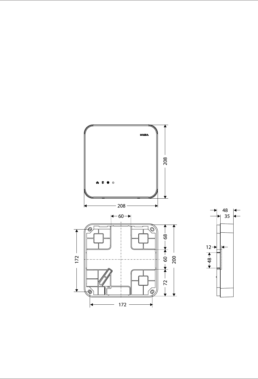
3.4.8 Dimensions/Weight
• Length: 208 mm
• Width: 208 mm
• Depth: 48 mm
• Weight: approx. 0.6 kg
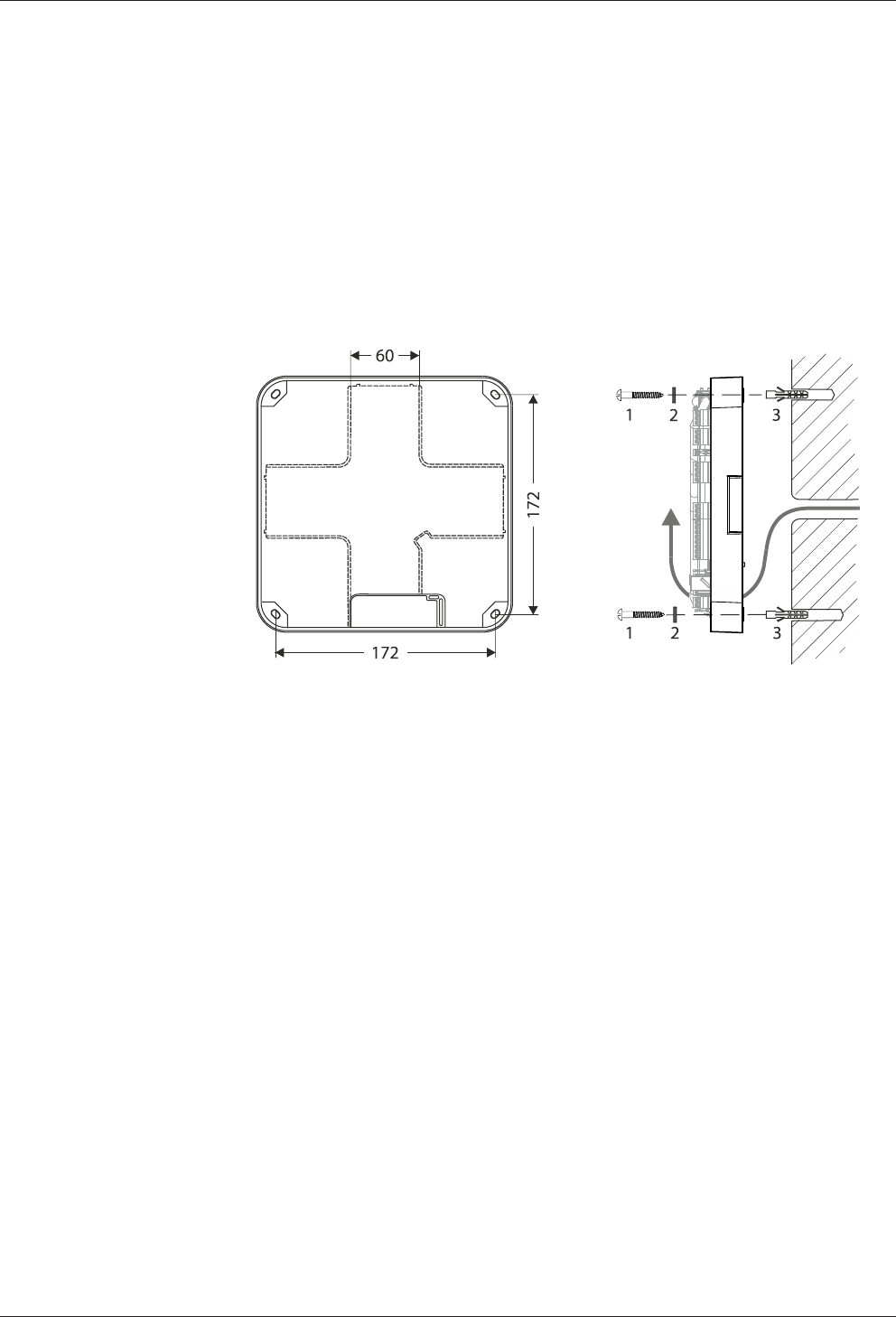
3.4.9 Dimensional drawings
Dimensions in mm
Technical Manual Product Description
2104045376 - 05/2016Kaba access manager 92 30
3.5 Conformity
This product conforms to the following standards:
EN 60950-1:2006 + A11:2009 + A1:2010 + A12:2011
EN 300 330-1 V1.7.1
EN 300 330-2 V1.5.1
EN 301 489-1 V1.9.2
EN 301 489-3 V1.6.1
EN 55022:2010, Class B
EN 55024:2010
according to the regulations of the EC Directive
1999/5/EC R&TTE Directive
The original Declaration of Conformity can be downloaded from
www.kaba.com/conformity in PDF format.
In addition, the product also conforms to the following standards:
UL 60950-1
UL 294, security performance level 1
RoHS This device complies with the regulations of the Directive 2011/65/EU of the Euro-
pean Parliament and of the Council of June 8, 2011, on the restriction of the use of
certain hazardous substances in electrical and electronic equipment.
FCC FCC Code of Federal Regulations, CFR 47, Part 15, Sections 15.205, 15.207,
15.215 and 15.225
FCC ID NVI-KAM9230-K5
FCC § 15.19
This device complies with Part 15 of the FCC rules. Operation is subject to the follow-
ing two conditions: (1) This device may not cause harmful interference, and (2) this
device must accept any interference received, including interference that may cause
undesired operation.
FCC § 15.21 (Warning Statement)
[Any] changes or modifications not expressly approved by the party responsible for
compliance could void the user’s authority to operate the equipment.
FCC § 15.105
Note: This equipment has been tested and found to comply with the limits for a Class
A digital device, pursuant to part 15 of the FCC Rules.
These limits are designed to provide reasonable protection against harmful interfer-
ence when the equipment is operated in a commercial environment. This equipment
generates, uses, and can radiate radio frequency energy and, if not installed and used
in accordance with the instruction manual, may cause harmful interference to radio
communications. Operation of this equipment in a residential area is likely to cause
harmful interference in which case the user will be required to correct the interfer-
ence at his own expense.

Product Description Technical Manual
22 04045376 - 05/2016 Kaba access manager 92 30
IC Industry Canada Radio Standards Specifications RSS-GEN Issue 4, Sections 8.8,
8.9 and 8.10 and RSS-210 Issue 8, Section A2.6 (Category I Equipment)
IC:11038A-KAM9230K5
ICES-003
This Class A digital apparatus complies with Canadian ICES-003.
Cet appareil numérique de la classe A est conforme à la norme NMB-003 du Canada.
Canada RSS-GEN 8.4
This device complies with Industry Canada’s licence-exempt RSSs. Operation is sub-
ject to the following two conditions:
(1) This device may not cause interference; and
(2) This device must accept any interference, including interference that may cause
undesired operation of the device.
Le présent appareil est conforme aux CNR d’Industrie Canada applicables aux ap-
pareils radio exempts de licence. L’exploitation est autorisée aux deux conditions
suivantes :
1) l’appareil ne doit pas produire de brouillage;
2) l’utilisateur de l’appareil doit accepter tout brouillage radioélectrique subi, même
si le brouillage est susceptible d’en compromettre le fonctionnement.
3.6 Labeling
Identification plate
The identification plate is located on the rear of the device.
The identification plate contains:
• Device name
• Item number
• Serial number
• Connection data (power supply)
• CE marking
• WEEE labeling acc. to DIN EN 50419
MAC address
An adhesive label with the MAC address of the device is located on the Ethernet re-
ceptacle.
Technical Manual Design and function
2304045376 - 05/2016Kaba access manager 92 30
4 Design and function
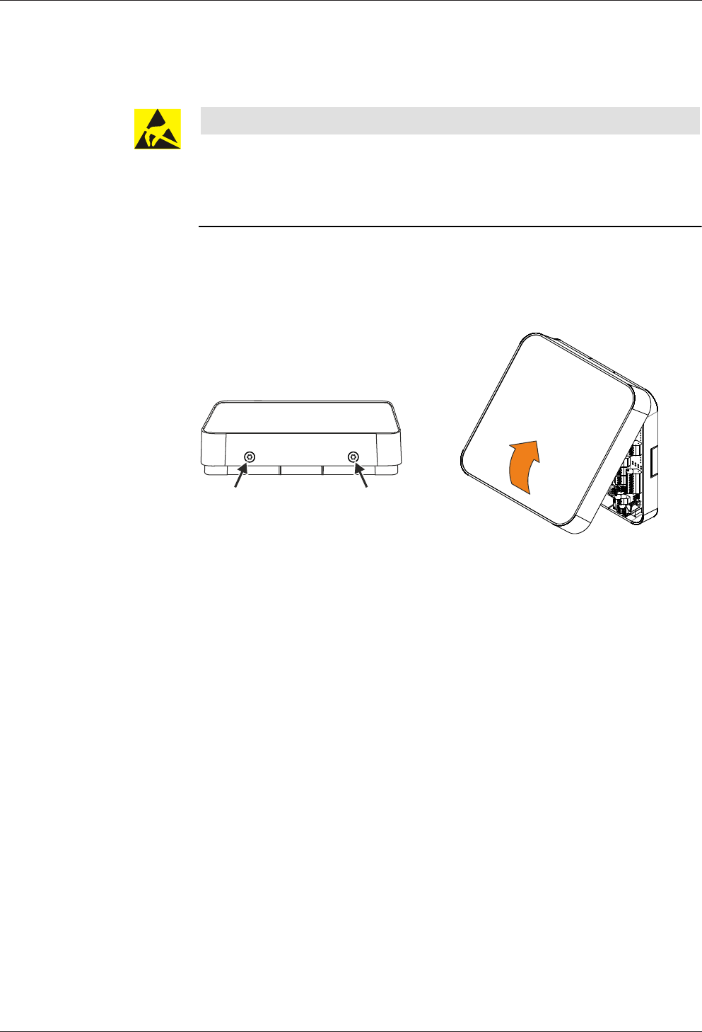
4.1 Opening the housing
NOTICE
Danger for electronic components due to electrostatic discharge.
Improper handling can damage or destroy electrostatically sensitive components on
printed circuit boards (PCB).
• General ESD protective measures must be observed and applied.
Remove the housing cover in the following way:
1. Remove two screws M3x8 (TORX 8) on the device bottom side.
2. Swivel the bottom side of the cover and disengage it at the top.
Design and function Technical Manual
24 04045376 - 05/2016 Kaba access manager 92 30
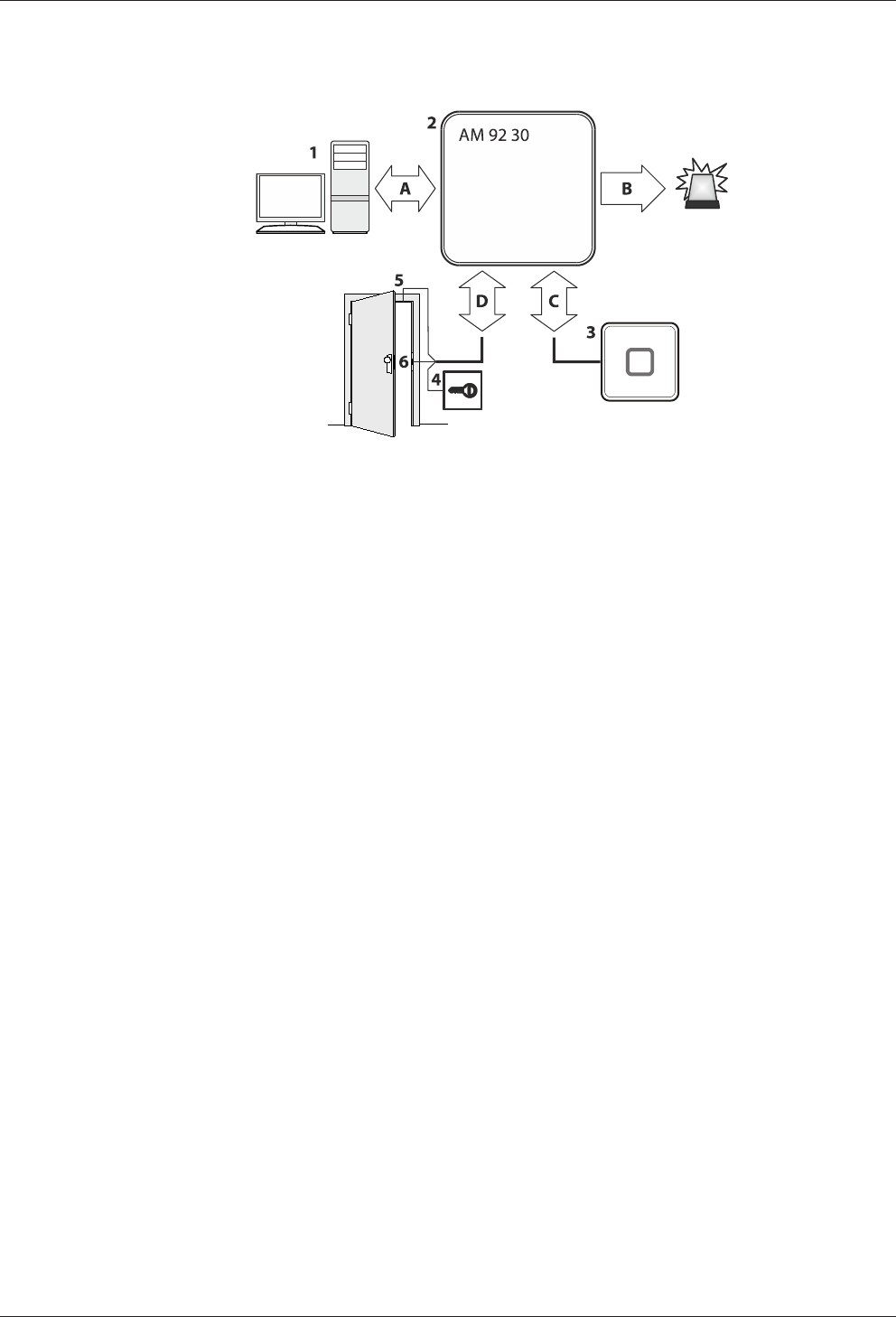
4.2 Functional principle
1 Host computer (superior system)
2 Kaba access manager 92 30
3 External readers
4 Door opener key
5 Door frame contact
6 Door-opener
A Communication with the superior host computer
B Alarm signals
C Badge data and user guidance
D Signals for door opening and monitoring
Technical Manual Design and function
2504045376 - 05/2016Kaba access manager 92 30
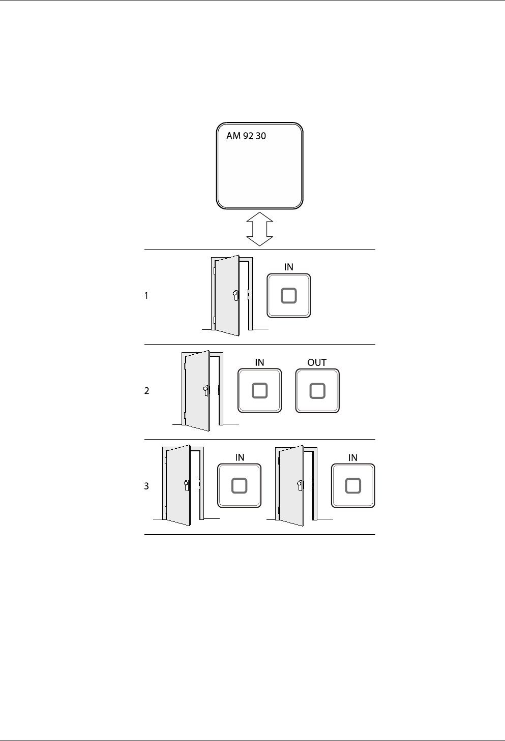
4.2.1 Typical applications
The Kaba access manager 92 30 is designed for control of one or maximum two ac-
cesses with a total of 2 readers. The following overview shows the three typical appli-
cations.
The terminal software offers basically the possibility to configure further sub-variants.
1 Access with reader for entry
2 Access with reader for entry and reader for exit
3 Two accesses with one reader for each entry respectively

Design and function Technical Manual
26 04045376 - 05/2016 Kaba access manager 92 30
4.2.2 Superior system
Communication with the superior system (host computer) takes place via the Ether-
net network.
The superior system serves for centralized management of authorizations, access and
room profiles, system configuration and alarm management.
4.2.3 Reader
The data collection of identification data is performed via external readers.
Up to 2 readers can be connected. The readers which are supported depend on the
device variant.
Kaba access manager 92 30 with connections for readers via Wiegand
Kaba access manager supports the connection of two readers via the Wiegand inter-
face.
• Connection individually via Wiegand interface
• Data collection of identification data
• Control of optical and acoustic signal generators
• Power supply via the access manager
Kaba access manager 92 30 with connections for registration units and readers
via RS-485
The Kaba access manager supports connection of two Kaba RFID registration units
via the coaxial cable.
Alternatively, up to 2 readers/subterminals can be connected via the RS-485 inter-
face.
Registration unit:
• Connection individually via coaxial cable
• Data collection of identification data
• CardLink validation and update
• Control of optical and acoustic signal generators
• Keypad is supported
• Power supply via the access manager
Readers via RS-485:
• Connection via RS-485 partyline in bus or star wiring
• Data collection of identification data
• CardLink validation
• Control of optical and acoustic signal generators
• Keypad is supported
• The inputs and outputs of subterminals can be used.
• Power supply via the access manager possible

Technical Manual Design and function
2704045376 - 05/2016Kaba access manager 92 30
4.2.4 Function of the inputs
The function of the inputs depends on the configuration. The following functionali-
ties are possible:
Door frame contact
With a door frame contact, the access manager is able to detect if and how long the
door is open. If the maximum allowed door-opening time has elapsed and the door is
still open, the access manager sends an alarm record to the host computer. A relay
can be activated additionally.
Door opener key
A door-opener key can be connected if no subterminal is mounted in the interior and
if the door is not equipped with a door handle. If the door-opener key is pressed the
respective door-opener relay is activated.
Bolt contact
With the bolt contact, the access manager can identify the door’s current bolt posi-
tion. If the bolt is not in the expected position after the end of the allowed time, the
access control manager sends an alarm record to the host computer.
Door handle contact
With the door handle contact, the access manager can identify the door handle’s cur-
rent position. If the door frame contact responds without previous activation of the
door opener or pressing of the door handle, the access manager sends an alarm
record to the host computer.
Pass through
This input monitors if access has really taken place. To this end, a light barrier, con-
tact mat, etc., is connected to this input which reports if a person has passed
through.
The functions of door frame contact and door opener key are preset for the inputs
per access.
4.2.5 Function of the outputs
The function of the individual outputs depends on the configuration. Important func-
tions are:
Door-opener relay
A door opener can be connected to the door opener relay. The door-opener relay is
activated if the access manager releases access, e.g., after an authorized booking.
Alarm relay
Depending on the configuration, the alarm relay can be activated in case of an au-
thorized booking or alarm (e.g. door breakup).

Design and function Technical Manual
28 04045376 - 05/2016 Kaba access manager 92 30
4.3 Access control with B-Client AC30
4.3.1 Operating states
The access manager allows the following operating states:
• Online
• Fast online
• Offline
• Autonomous
4.3.1.1 Online
The “Online” operating mode is recommended if the arising data records must be
permanently available in the host computer.
After a booking, the access manager carries out the programmed checks and writes
the test result as an error ID into the registration record. The registration record is
transferred to the host computer. After that, the access manager expects a logical
booking response from the host computer. With this response, the access manager is
informed by the host whether or not the booking is authorized.
If the access manager does not receive a logical booking response from the host
computer, it will change to offline mode and decide itself, according to the pro-
grammed verifications, if the booking is authorized or not. As soon as the host com-
puter is accessible again, the access manager changes back to online mode. All data
records stored in the meantime in Offline mode are transmitted to the host com-
puter.
4.3.1.2 Fast online
In contrast to online mode, a query to the host computer takes only place if the inter-
nal booking response is negative. Individual access points can be set to Fast Online.
4.3.1.3 Offline
After a booking has been made, the access manager carries out the programmed
checks and decides immediately by way of an internal booking response whether
or not the booking is authorized. If the host computer is available, registration data
records of authorized and unauthorized bookings (depending on the set parameters)
will be transferred immediately. Otherwise, the registration records will be stored in
the access manager. As soon as the host computer is available, all data records stored
since the last transmission are transferred to the host computer.
4.3.1.4 Autonomous
After a booking has been made, the access manager carries out the programmed
checks and decides immediately by way of an internal booking response whether
or not the booking is authorized. Registration data records of authorized or unautho-
rized bookings are stored in the access manager, depending on the set parameters.
If the host computer is available, any existing error and alarm records will be trans-
mitted to the host computer.
The stored registration data records are transmitted to the host computer with a spe-
cial data record after request. Once transferred to the host, the data records will be
deleted in the access manager.

Technical Manual Design and function
2904045376 - 05/2016Kaba access manager 92 30
4.3.1.5 Overview of the most important differences of the operating modes
Proceeding Online Fast
Online
Offline Autono-
mous
The host decides whether a book-
ing is valid
X (X)1
The access manager decides
whether a booking is valid
(X)2(X)1.2 X X
Transmission of the registration
records
XXX
Transmission of the registration
records only upon request
X
Storage of the registration records
in the access manager
(X)3(X)3(X)3X
Transmission of error and alarm
records
XXXX
Explanations
1 A request to the host takes only place if the internal booking response is nega-
tive.
2 If there is no booking response from the host, the control decides itself if the
booking is authorized or not.
3 If the host computer is not available, the registration data will be stored in the ac-
cess manager. As soon as the host computer is available, the registration records
will be transmitted.
Design and function Technical Manual
30 04045376 - 05/2016 Kaba access manager 92 30
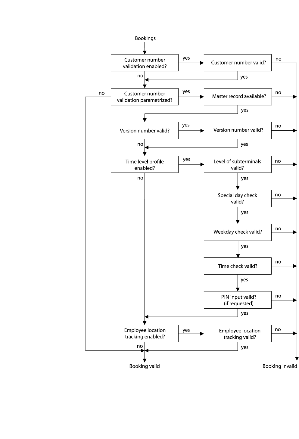
4.3.2 Sequence of authorization checks
Technical Manual Design and function
3104045376 - 05/2016Kaba access manager 92 30
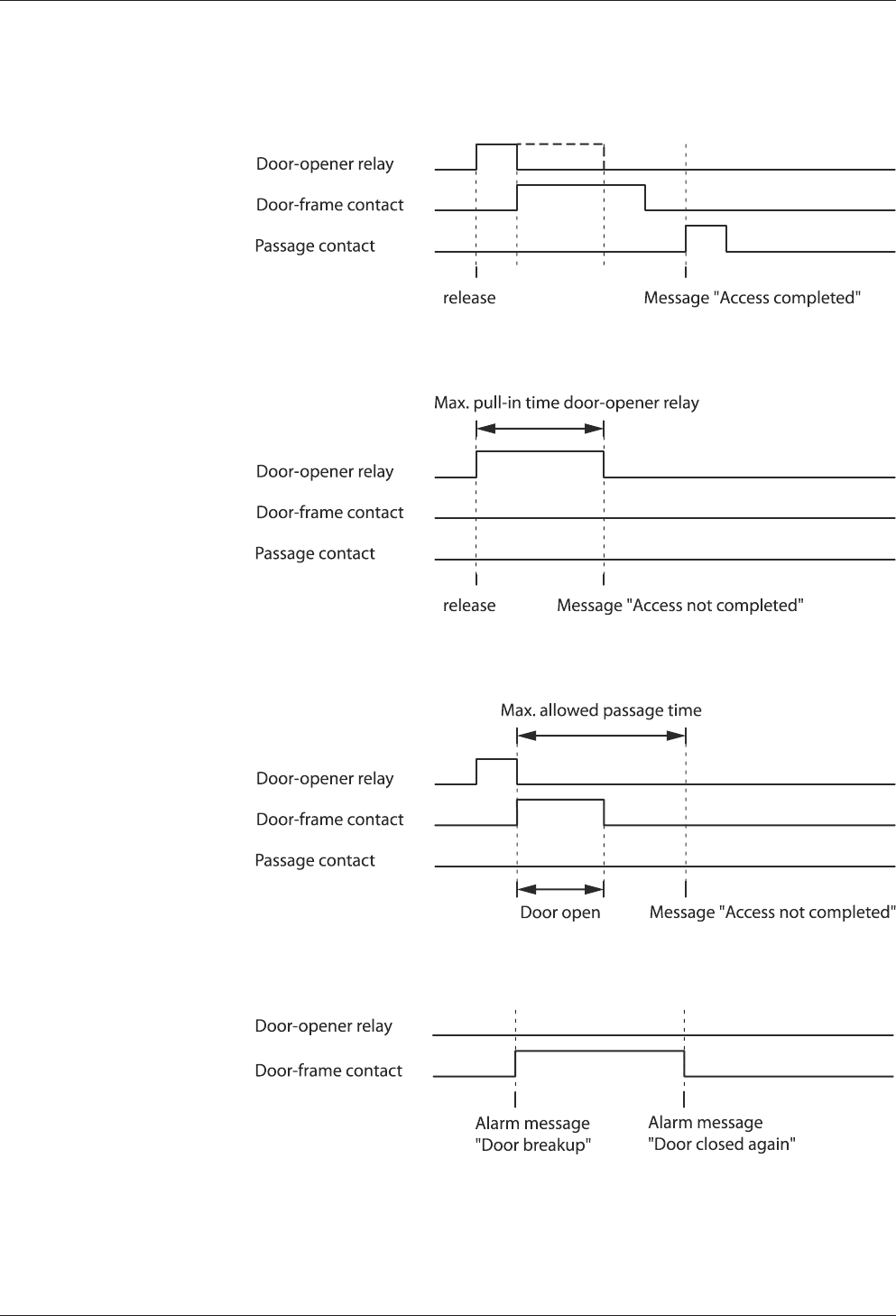
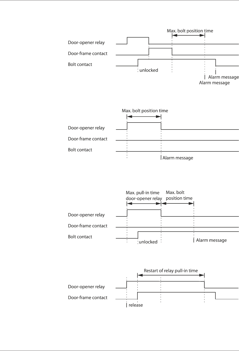
4.3.3 Examples of door surveillance time sequences
4.3.3.1 Normal sequence with pass through control
4.3.3.2 Door is not opened after release (extended access control)
4.3.3.3 No pass through (extended access control)
4.3.3.4 Door breakup (door monitored in basic state)
Design and function Technical Manual
32 04045376 - 05/2016 Kaba access manager 92 30
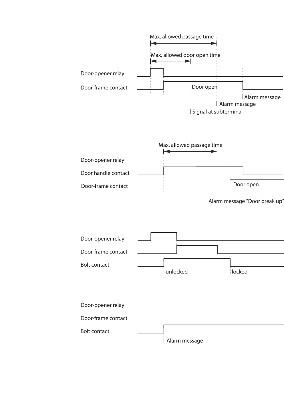
4.3.3.5 Door open too long
4.3.3.6 Time exceeded access with door handle
4.3.3.7 Bolt monitoring, normal sequence
4.3.3.8 Bolt monitoring, bolt message without door release
Technical Manual Design and function
3304045376 - 05/2016Kaba access manager 92 30
4.3.3.9 Bolt monitoring, bolt position time exceeded when locking
4.3.3.10 Bolt monitoring, bolt position time exceeded when unlocking
4.3.3.11 Bolt monitoring, bolt position time exceeded when locking – after door has not been
opened
4.3.3.12 Normal sequence with motor-driven door
Design and function Technical Manual
34 04045376 - 05/2016 Kaba access manager 92 30
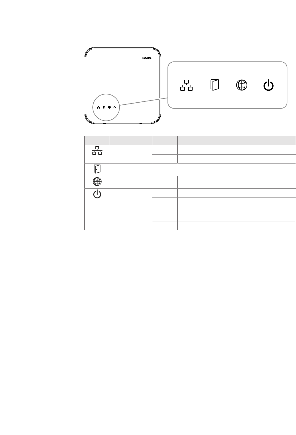
4.4 Light emitting diodes
The housing front contains 4 light emitting diodes for status display.
Icon Designation Signal Meaning
Ethernet yellow Data transfer is active
Off No data transfer
Device status See chapter 4.4.1
no function - -
Power green Device power supply is stable
red Load of the device power supply is within the
limits. Application of further load leads to the
switch-off due to overload.
Off no power supply
Technical Manual Design and function
3504045376 - 05/2016Kaba access manager 92 30
4.4.1 Device status
The status of the device is indicated by the LED with the following icon.
Status LED
The signal sequences and their meaning depend on the terminal software used.
4.4.1.1 B-Client AC30 terminal software
The B-Client AC30 terminal software signals different states and sequences via the
State LED as follows.
System start
After starting the device, the system performs several steps until it is ready for use
These steps are signaled as follows:
Signal Meaning
Yellow (approx. 40 sec.) The operating system is started
Yellow flashing (approx. 10
sec.)
Waiting for possible key actuation (cold start)
Red (approx. 5 sec.) Waiting for possible key actuation (default IP)
Green, then short green
flashing signals
The terminal software is started.
Status and error states after system start
Signal Meaning
Green Terminal software was started successfully.
Red/green flash-
ing
1-Click installation active
The device is waiting for registration by the host (B-COMM).
Yellow flashing Terminal software was not started.
Reason: No or invalid software license
Red flashing Terminal software could not be started.
Reason: Program or configuration file(s) not available or defec-
tive
Green flashing
(long green flash-
ing signals)
Terminal software must be restarted.
Reason: Network parameters were changed
If the terminal software cannot be started by the system, a file named “appstate” will
be created. This file contains an entry indicating the reason for the abort.
The “appstate” file is stored in the /home/admin/ directory.

Installation Technical Manual
36 04045376 - 05/2016 Kaba access manager 92 30
5 Installation
5.1 Installation conditions
5.1.1 General
An accurate installation of all components is a basic requirement for a properly func-
tioning device. The following installation instructions must be adhered to.
5.1.2 Installation site
The access manager is installed near the access. The device is designed for the direct
mounting on the wall. Depending on the conditions, the device can also be mounted
in suspended ceilings, wall recesses etc.
The access manager should be installed in the interior of the area to be secured.
The access manager must be installed exclusively in interiors.
Electromagnetic fields
The device must not be installed in the area of strong electromagnetic fields caused
by switching power supply, power lines, phase controllers, etc.!
5.1.3 Connections
The following connectors must have been prepared at the installation site of the ac-
cess manager:
• Ethernet network connection for host communication
For PoE power supply of the access manager, a PSE (Power Sourcing Equipment)
must be provided on the network cable for power feeding.
Possible methods for feeding the power supply via the PSE:
– End span (direct supply, e.g. via PoE switch)
– Midspan (supply via intermediate sources, e.g. PoE injector)
• 24 V DC power supply for the access manager (only for external 24 V DC power
supply as an alternative to the PoE power supply)
• Signal lines to door openers and contacts
• Coaxial lines to the registration units and/or data lines to the readers.
The installation lines have to be flush with the surface or be laid in the vandal-proof
area.
Technical Manual Installation
3704045376 - 05/2016Kaba access manager 92 30
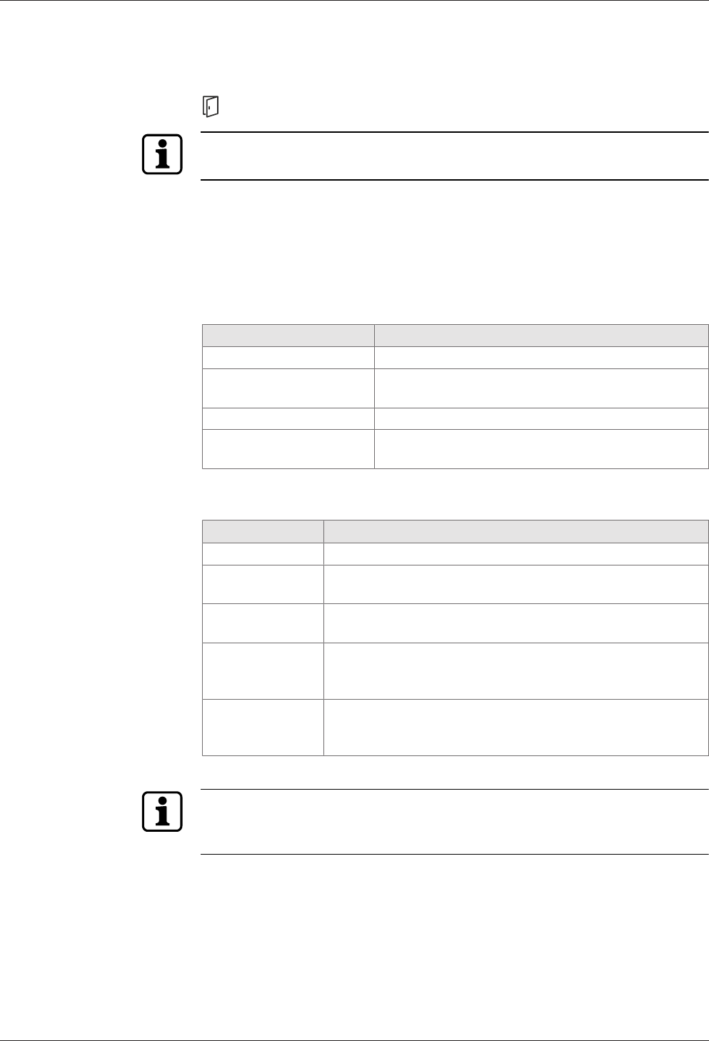
5.1.4 Cable entry
The installation lines can be routed to the device from behind, from the side, from
above and below.
There are holes in the bottom part of the housing, on the sides and on the top and
bottom; they can be removed if necessary,
The lines are routed in a duct in the lower part of the rear side, there is the gland to
the connections on the front side.
NOTICE
Ensure sufficient line lengths on the installation site.
When inserting the lines from the rear (center of the housing), the installation lines
and network cable with the plug protrude from the wall for approx. 35 cm.
Installation Technical Manual
38 04045376 - 05/2016 Kaba access manager 92 30
5.2 Installation diagram
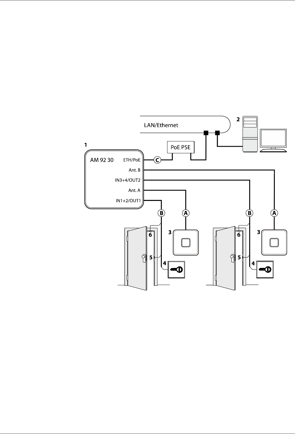
5.2.1 Access control with registration unit
Example:
• Access control with RFID registration units
• PoE power supply of the access manager
Method for feeding in the power supply via the PSE (Power Sourcing Equip-
ment):
– End span (direct supply, e.g. via PoE switch)
– Midspan (supply via intermediate sources, e.g. PoE injector)
1 Kaba access manager 92 30
2 Host computer
3 Registration unit
4 Door opener key
5 Door-opener
6 Door frame contact
Installation lines
A Coaxial cable to the registration unit
B Line to the door contact, the door opener key, and the door opener
C Ethernet network cable
Technical Manual Installation
3904045376 - 05/2016Kaba access manager 92 30
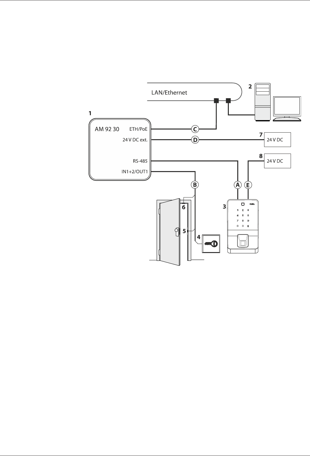
5.2.2 Access control with reader via RS-485
Example:
• Access control with biometric reader via RS-485
• External power supply of the biometric reader
• External power supply of the access manager
1 Kaba access manager 92 30
2 Host computer
3 Biometric reader
4 Door opener key
5 Door opener
6 Door frame contact
7 External 24 V DC power supply for the access manager
8 External 24 V DC power supply for the biometric reader
Installation lines
A Data line to the reader (RS-485)
B Line to the door contact, the door opener key, and the door opener
C Ethernet network cable
D Power supply line Access manager
E Power supply line Biometric reader
Installation Technical Manual
40 04045376 - 05/2016 Kaba access manager 92 30
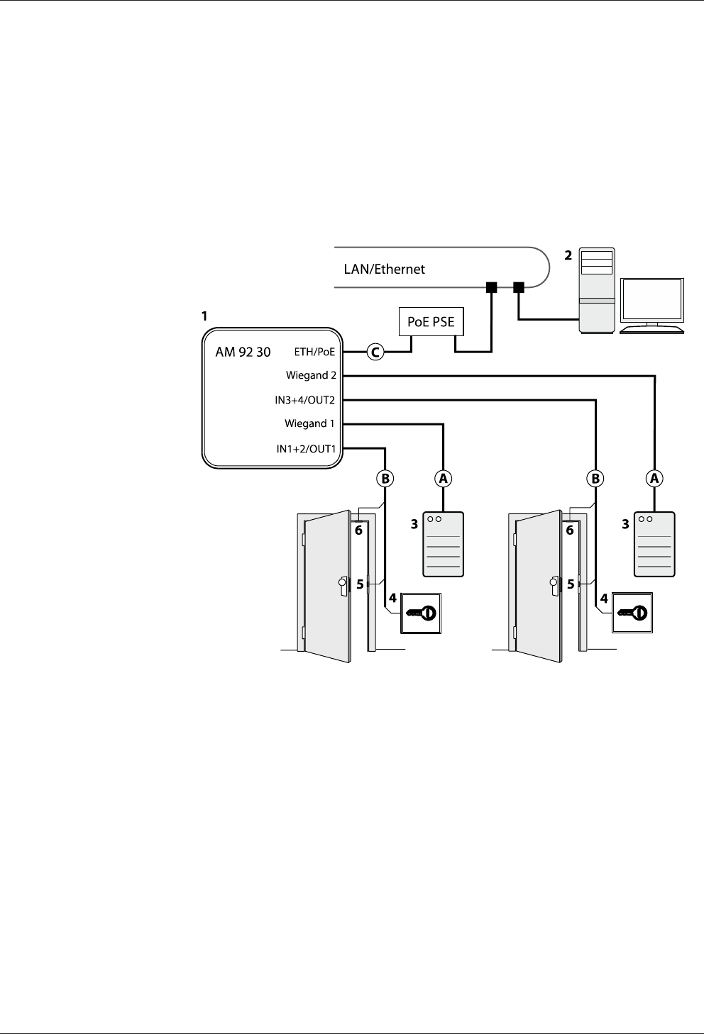
5.2.3 Access control with readers via Wiegand
Example:
• Access control with external readers via Wiegand interface
• PoE power supply of the access manager
Method for feeding in the power supply via the PSE (Power Sourcing Equip-
ment):
– End span (direct supply, e.g. via PoE switch)
– Midspan (supply via intermediate sources, e.g. PoE injector)
1 Kaba access manager 92 30
2 Host computer
3 External reader equipped with Wiegand interface
4 Door opener key
5 Door-opener
6 Door frame contact
Installation lines
A Data cable to the reader (Wiegand)
B Line to the door contact, the door opener key, and the door opener
C Ethernet network cable
Technical Manual Installation
4104045376 - 05/2016Kaba access manager 92 30
5.3 Installation lines
5.3.1 Ethernet
Network cable with RJ45 plug, Line requirement: CAT.5 E or higher quality.
5.3.2 Power supply of the reader
For short distances of up to 20 meters max., a single cable may be used for the power
supply for the reader and data line. A separate power supply cable needs to be pro-
vided for longer distances.
Recommended cable: 1 x 2 x 0.6 mm or 1 x 2 x AWG 24.
In case of long lines, the voltage drop due to line resistance will have to be consid-
ered.
5.3.3 Data line to reader/subterminal
Connection to the readers is performed via partyline, a 2-wire RS-485 interface. For
this connection, you may choose a star topology or a bus topology.
No further signals or voltages may be transmitted via the data cable to the reader,
for example door-opener activation, door-frame contact, etc. (exception power sup-
ply up to a line length of 20 m).
The shielding of the data line is generally connected on both sides.
The complete bus network (master lines and stubs) may be up to 1,200 m long. One
stub must not exceed 100 m.
Line requirements:
Shielded line with twisted wire pairs. Cables with wire diameter from 0.25 mm2 to 1
mm2 can be used.
Recommended cable:
CAT.5 S/UTP 4 x 2 AWG 24 or AWG 22 (according to EIA/TIA568).
5.3.4 Line to the door opener, the door opener key, and the door contacts
Line requirements: Cable diameters from 0.5 mm to 0.8 mm.
Recommended cable: CAT.5 S-UTP 4 x 2 AWG 24 or AWG 22 (according to EIA/
TIA568) or higher.
5.3.5 Coaxial cables to registration units
Registration units are connected to the access manager via coaxial cables The coaxial
cable transfers the HF signals from the RFID antenna, keyboard data and trigger data
for the optical and acoustic signal generators.
Line requirements: Coaxial cable 50 ohms, type RG174/U.
Maximum cable length: 30 m
Recommended cable length: < 10 m
5.3.6 Line to the Wiegand reader
Line requirements: Shielded line 6 x 0.6 mm (0.34 mm2) or 6 x 22 AWG
Maximum line length: 10 m
Length and technical design of the line must comply with the requirements speci-
fied by the reader manufacturer.
Installation Technical Manual
42 04045376 - 05/2016 Kaba access manager 92 30
5.4 Wall mounting
When feeding the cable from the side, top or below, first, provide holes for the entry
of the installation lines. Not necessary for cable entry from the rear.
The housing is mounted directly to the wall using screws/dowels. There are three
oval fastening holes for fastening in the housing.
Fastening material (included in the delivery):
• 4 round-head wood screws DIN 96, diam. 4.5 x 35 (1)
• 4 washers (2)
• 4 dowels S6 (3)
The washers absorb mechanical tensions in case of slightly uneven surfaces and
cover the fastening hole completely once the screw has been tightened. The deliv-
ered washers must also be used if you use other fastening screws (depending on the
mounting surface).
In case of soft mounting surfaces, make sure that the housing is not pressed into the
surface when mounting it. The unevenness of the mounting surface may not exceed
0.5 mm. The unevenness of the mounting surface may have to be compensated for
or adjusted by means of suitable measures (e.g. washers).
The installation lines are led down in the duct on the rear side of the device and then
to the front side of the device with connections. Make sure that the lines are not
squeezed or buckled during mounting.
Technical Manual Installation
4304045376 - 05/2016Kaba access manager 92 30
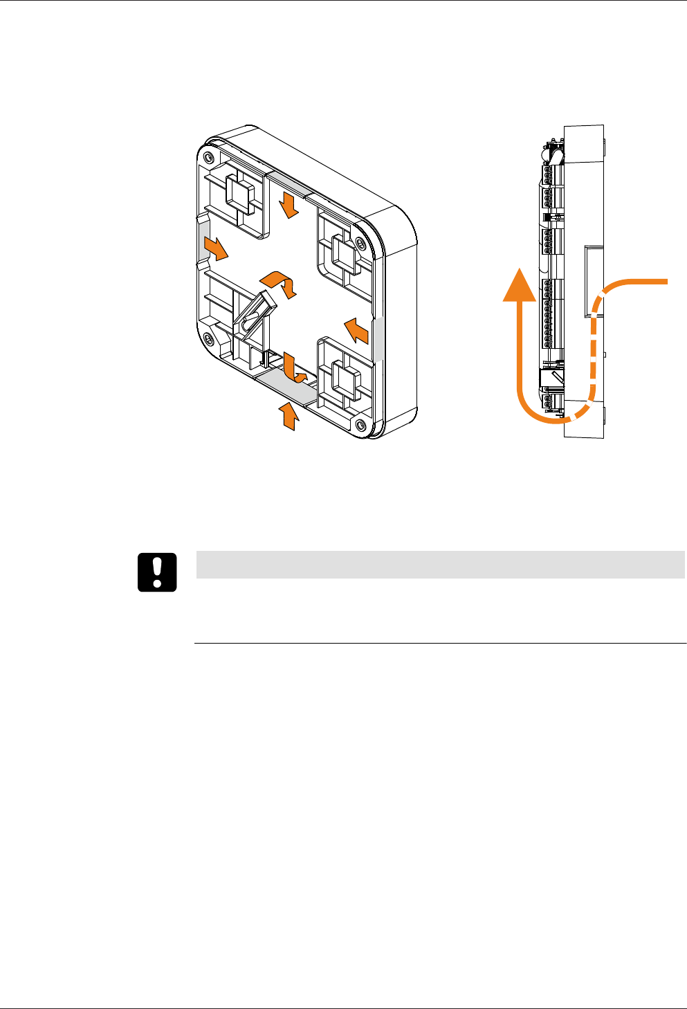
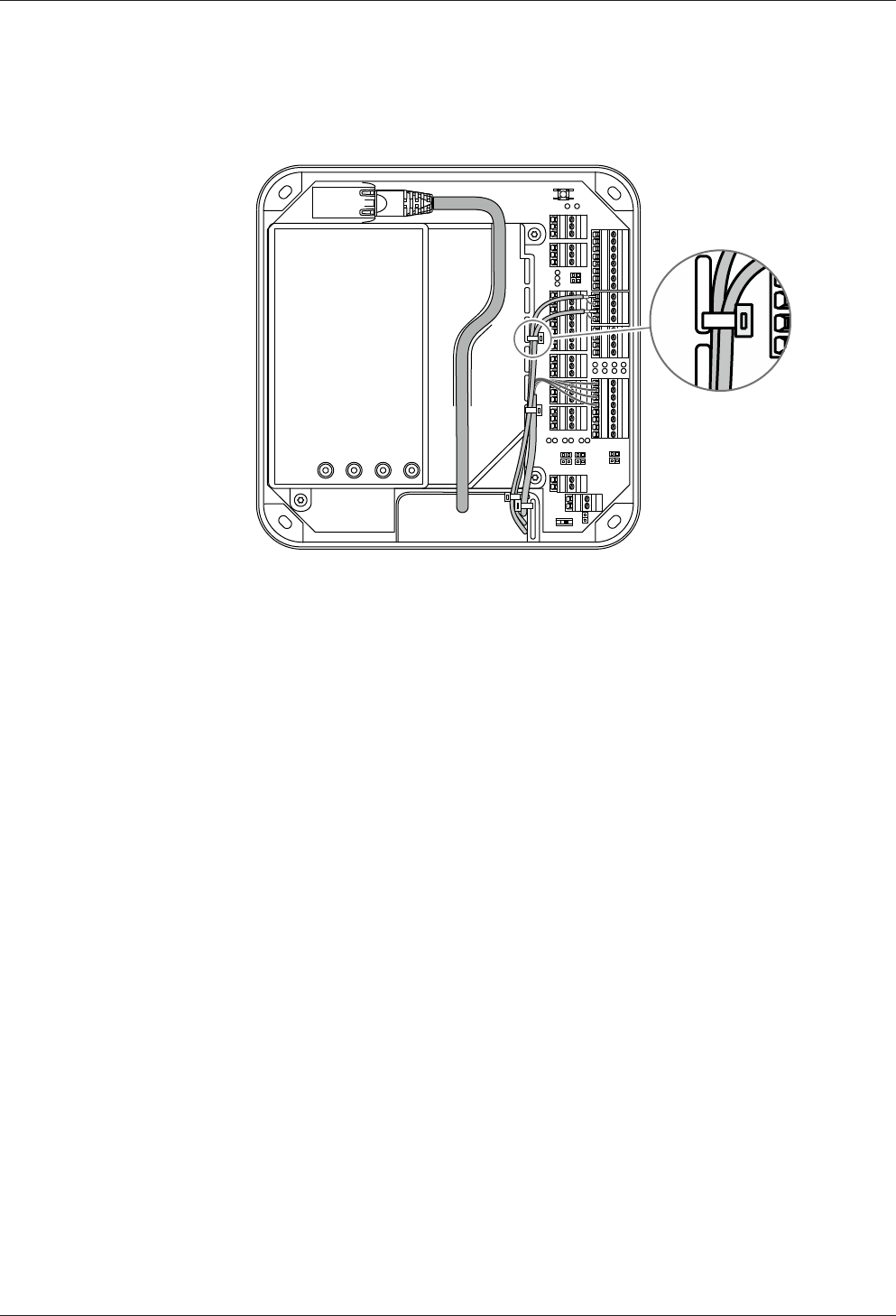
5.5 Cable routing
The installation lines are guided through an opening on the bottom side of the de-
vice from the rear side to the front side of the device.
The cable passage and the internal cover have eyelets for fastening of installation
lines by means of cable ties (not included in the scope of delivery).
For the network cable, there is a routing duct on the inner cover.
Installation Technical Manual
44 04045376 - 05/2016 Kaba access manager 92 30
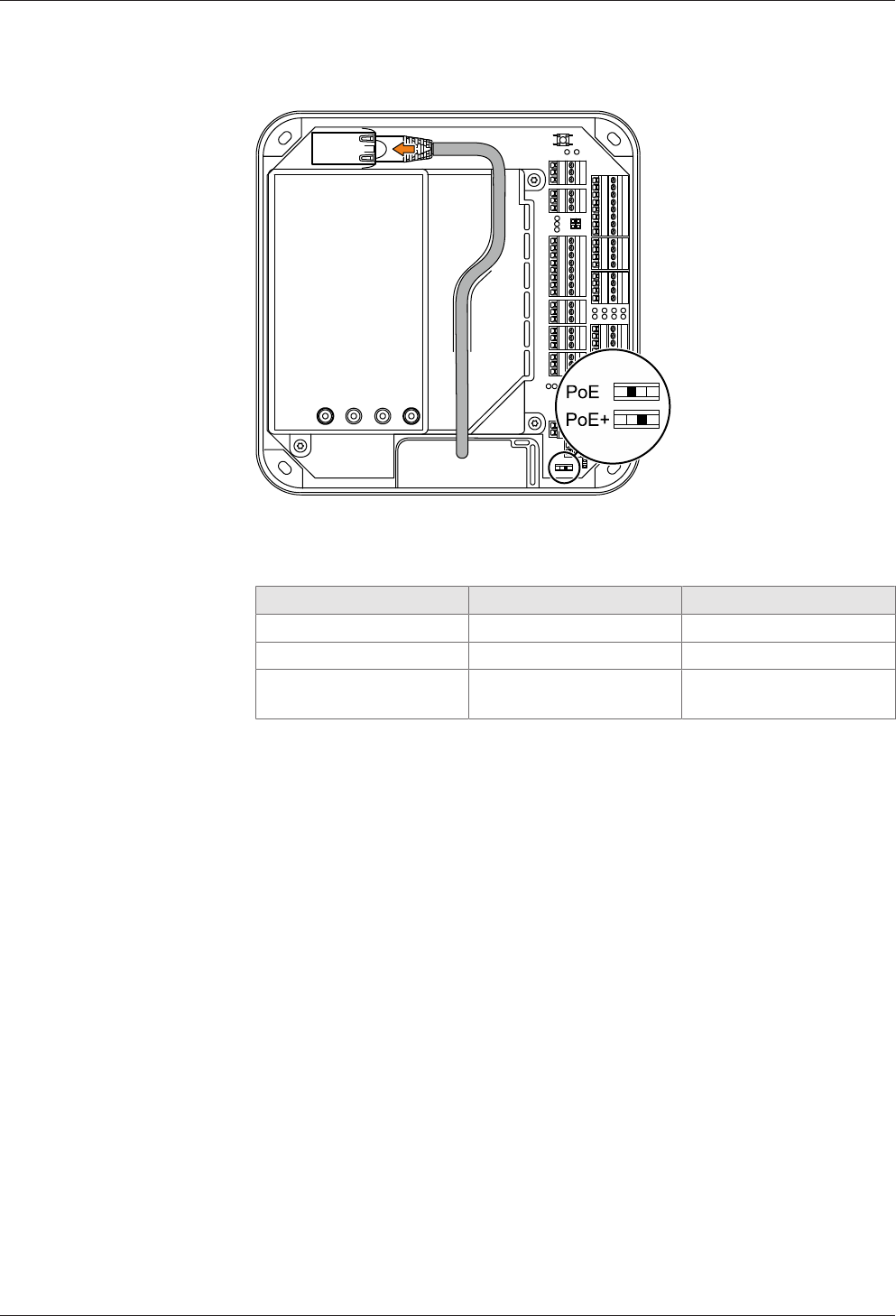
5.6 Setting the PoE switches
Depending on the power supply type, the PoE switch must be set as described be-
low.
Power supply Standard/Power Switch position
PoE IEEE 802.3af (12.95 W) PoE
PoE+ IEEE802.3at (25.5 W) PoE+
External 24 V DC power
supply unit
12-60 W PoE+
In case of power supply via an external power supply unit, the switch position PoE+ is
required to prevent the access manager from limiting the power for external con-
sumers.
Technical Manual Installation
4504045376 - 05/2016Kaba access manager 92 30
5.7 Connections
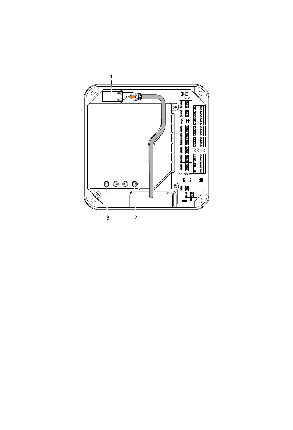
5.7.1 Network connection
Establishing the network connection
Plug in the network cable into the Ethernet receptacle (1) and fasten it in the gland
on the cover.
If the power supply is correct, the Power LED (2) lights up in green after a short time.
Once the network connection has been established, the Ethernet LED (3) is flashing
in yellow.
Installation Technical Manual
46 04045376 - 05/2016 Kaba access manager 92 30
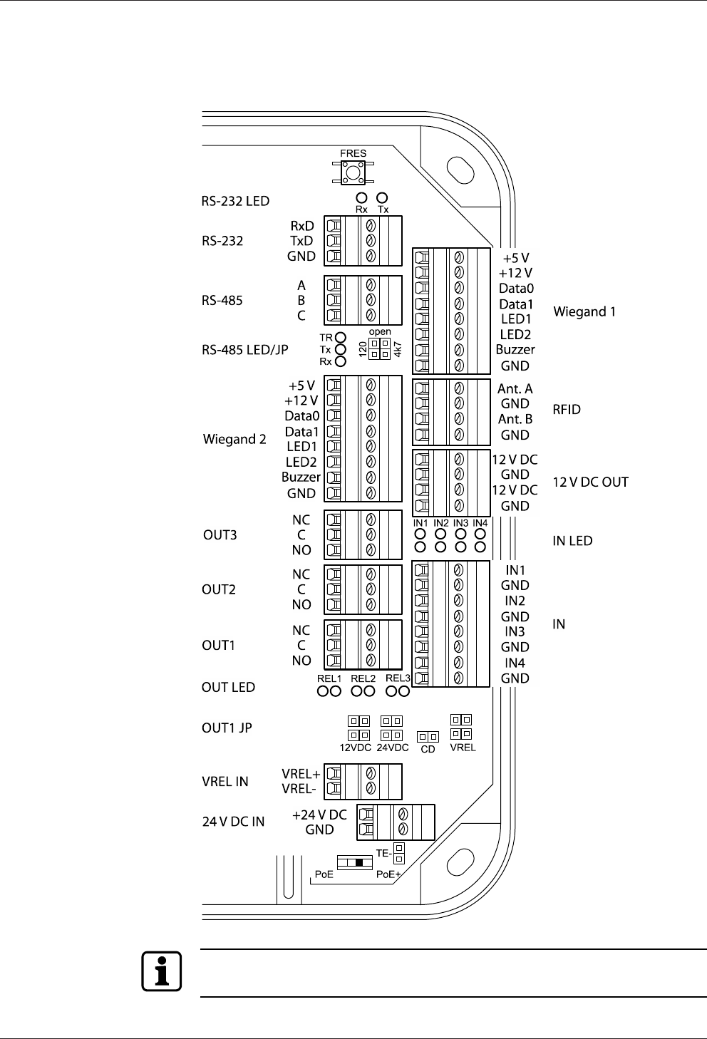
5.7.2 Overview of terminals
The following terminals are located in the connection area of the device.
Depending on the device variant, the terminals RFID or Wiegand 1+2 are not avail-
able.
Technical Manual Installation
4704045376 - 05/2016Kaba access manager 92 30
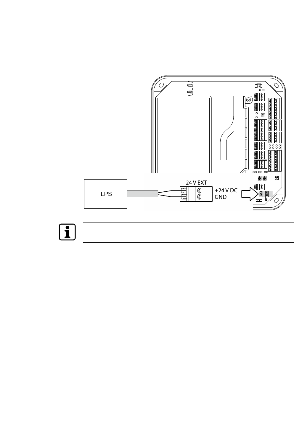
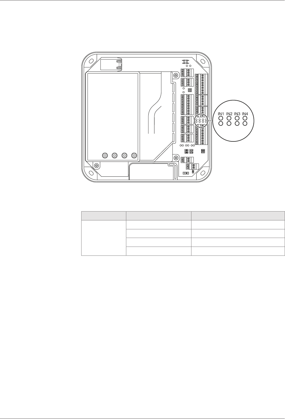
5.7.3 External 24 V DC power supply
As an alternative to the PoE power supply, the access manager can also be supplied
via an external 24 V DC power supply unit.
The connection of the external power supply is performed at terminal 24 V EXT.
The PoE switch [}5.6] must be set to "PoE+" position in this case.
Use only power supply units that fulfill the requirements of EN60950-1 as limited
power source.
Installation Technical Manual
48 04045376 - 05/2016 Kaba access manager 92 30
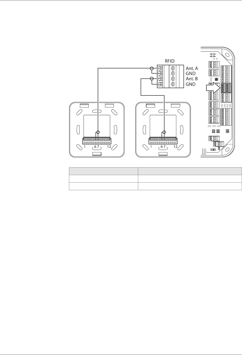
5.7.4 Registration units
Up to 2 registration units can be connected. The registration units A + B are con-
nected by means of the coaxial cable to the RFID input terminal.
Example: Connection of Kaba registration unit 90 01/90 02.
Connection designation Assignment
Ant. A/B Central conductor of coaxial cable
GND Shield of coaxial cable
Technical Manual Installation
4904045376 - 05/2016Kaba access manager 92 30
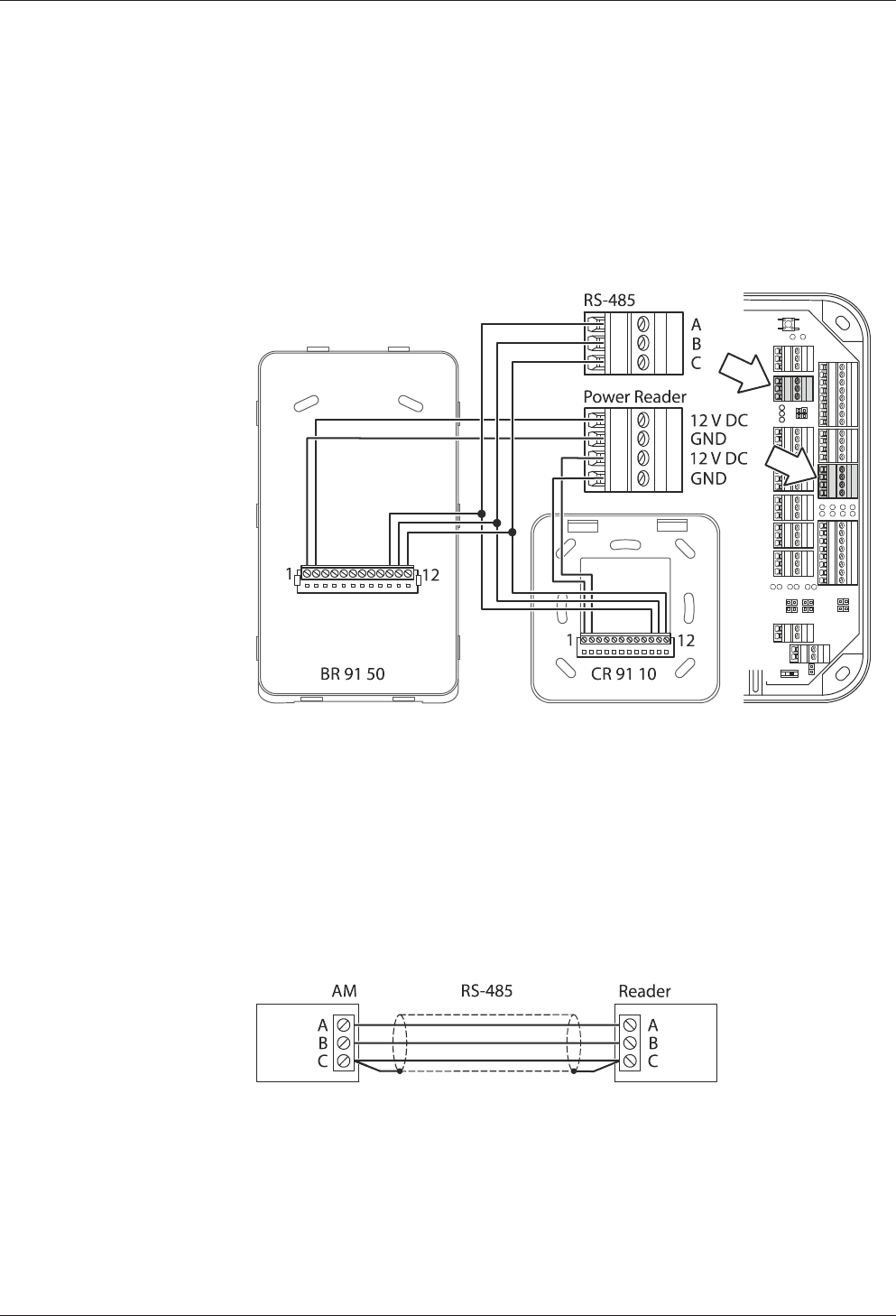
5.7.5 Readers via RS-485
The RS-485 interface serves for communication with readers. The RS-485 interface
(connections A, B, C) is operated in 2-wire mode. For this connection, you may
choose a star topology or a bus topology.
In case of star wiring, an additional support point terminal needs to be provided to
allow parallel distribution of RS-485.
Example: Connection of biometric reader 91 50 and compact reader 91 10 via RS-485
interface with 12 V DC power supply from the access manager.
5.7.5.1 Connection diagram
Twisted-pair cabling is used for the lines A and B. Lines are wired one-to-one, i.e., line
A of the access manager to line A of the reader and line B of the access manager to
line B of the reader.
5.7.5.2 Shielding
The data line shielding is generally connected on both sides. For this, connect the ad-
ditional wire to connection C.
Insulate the additional wire with heat-shrink tubing to avoid short-circuits!
5.7.5.3 Line lengths
The complete bus network (master lines and stubs) may be up to 1,200 m long. One
stub must not exceed 100 m.
Installation Technical Manual
50 04045376 - 05/2016 Kaba access manager 92 30
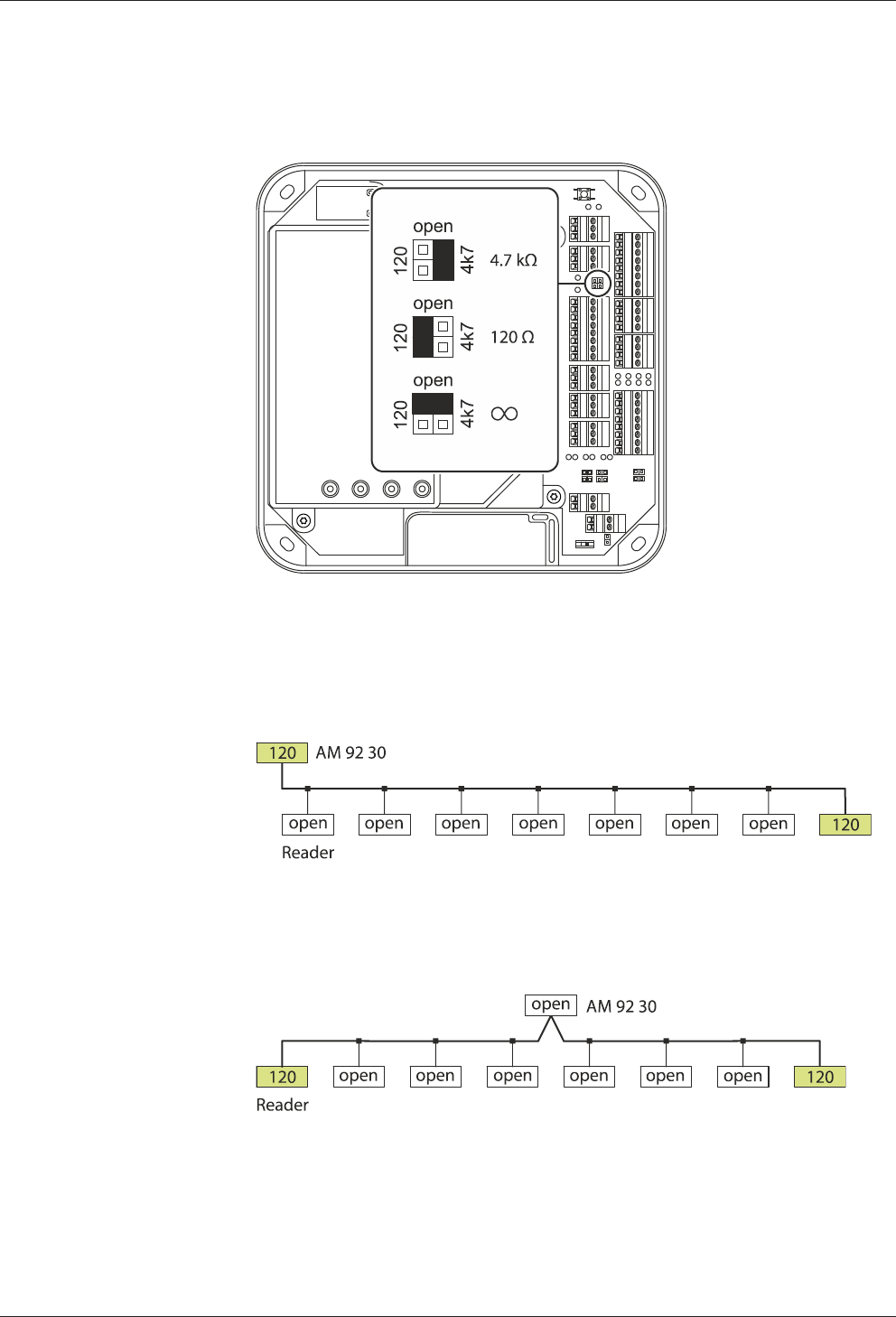
5.7.5.4 Bus termination
Below the RS-485 terminal, there is a jumper for setting the RS-485 terminating resis-
tor.
The selection of the terminating resistors depends on the connection architecture.
Bus with one root
The first device of the bus (access manager 92 30) and the last device of the bus
(reader 8) need a 120-ohm terminating resistor.
Bus with two roots
The last device of the first root and the last device of the second root need a 120-
ohm terminating resistor.
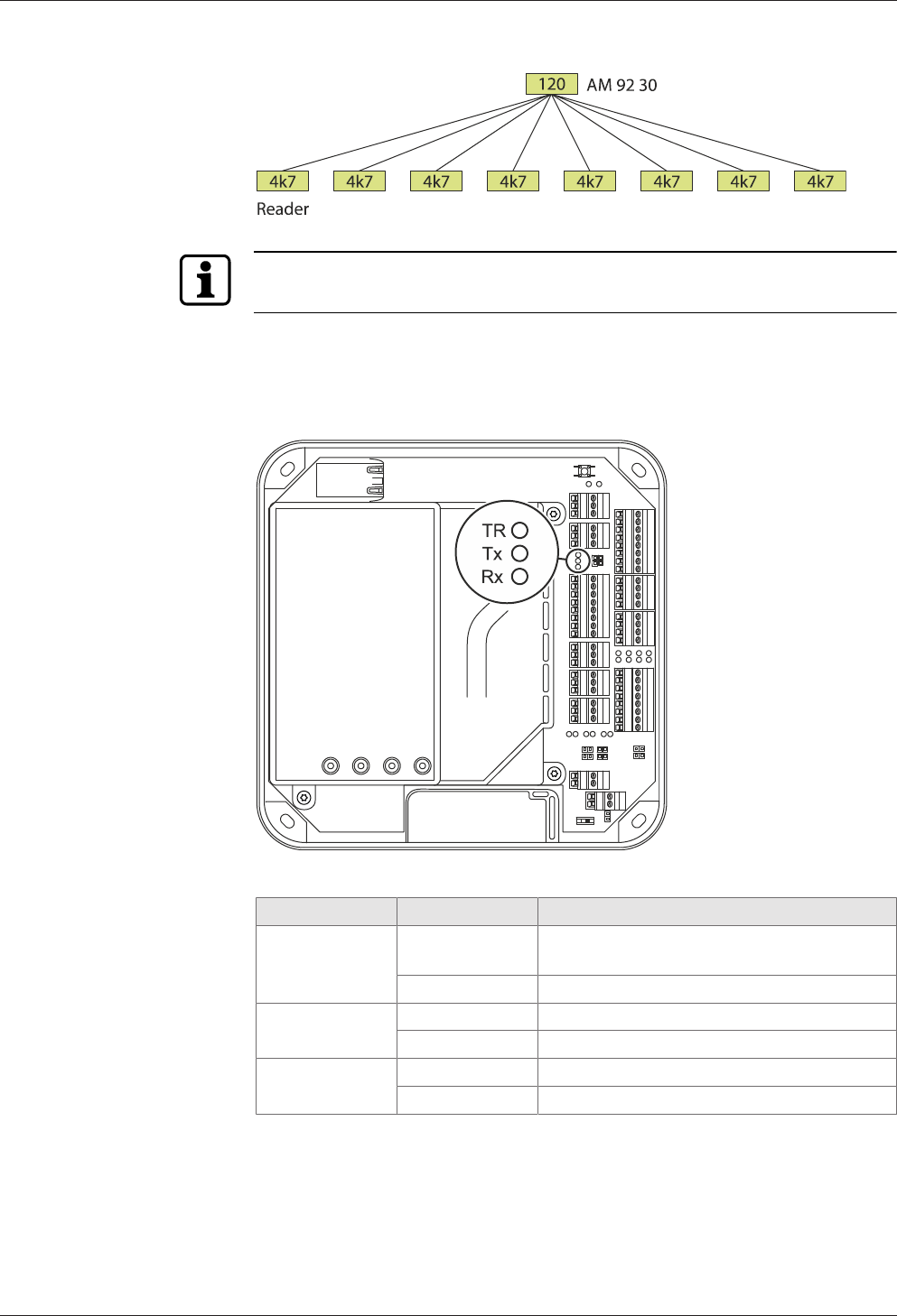
Star wiring
The example shows a star-type reader connection with 8 branches. The access man-
ager requires a 120-ohm terminating resistor. All readers require a 4.7-kOhm termi-
nating resistor.
Technical Manual Installation
5104045376 - 05/2016Kaba access manager 92 30
In readers, the terminating resistor can be set by means of a DIP switch.
5.7.5.5 RS-485 LEDs
Three light emitting diodes are located below the RS-485 terminal. They indicate the
states of the RS-485 interface.
The signals have the following meaning:
Designation Signal Meaning
TR Off Transmission direction, no readiness for re-
ception
Lit Readiness for reception
Tx Off No data
Lit/flashing Data are being sent
Rx Off No data
Lit/flashing Data are being received
Installation Technical Manual
52 04045376 - 05/2016 Kaba access manager 92 30
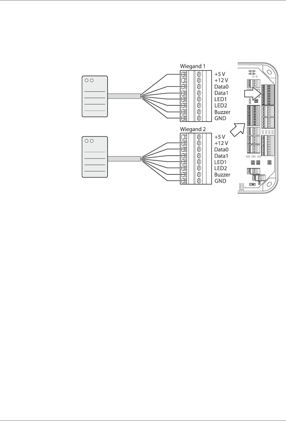
5.7.6 Readers via Wiegand
Two readers can be connected to the access manager via the Wiegand interface.
Example: Reader connection via Wiegand with 5 V and 12 V power supply from the
access manager.
Technical Manual Installation
5304045376 - 05/2016Kaba access manager 92 30
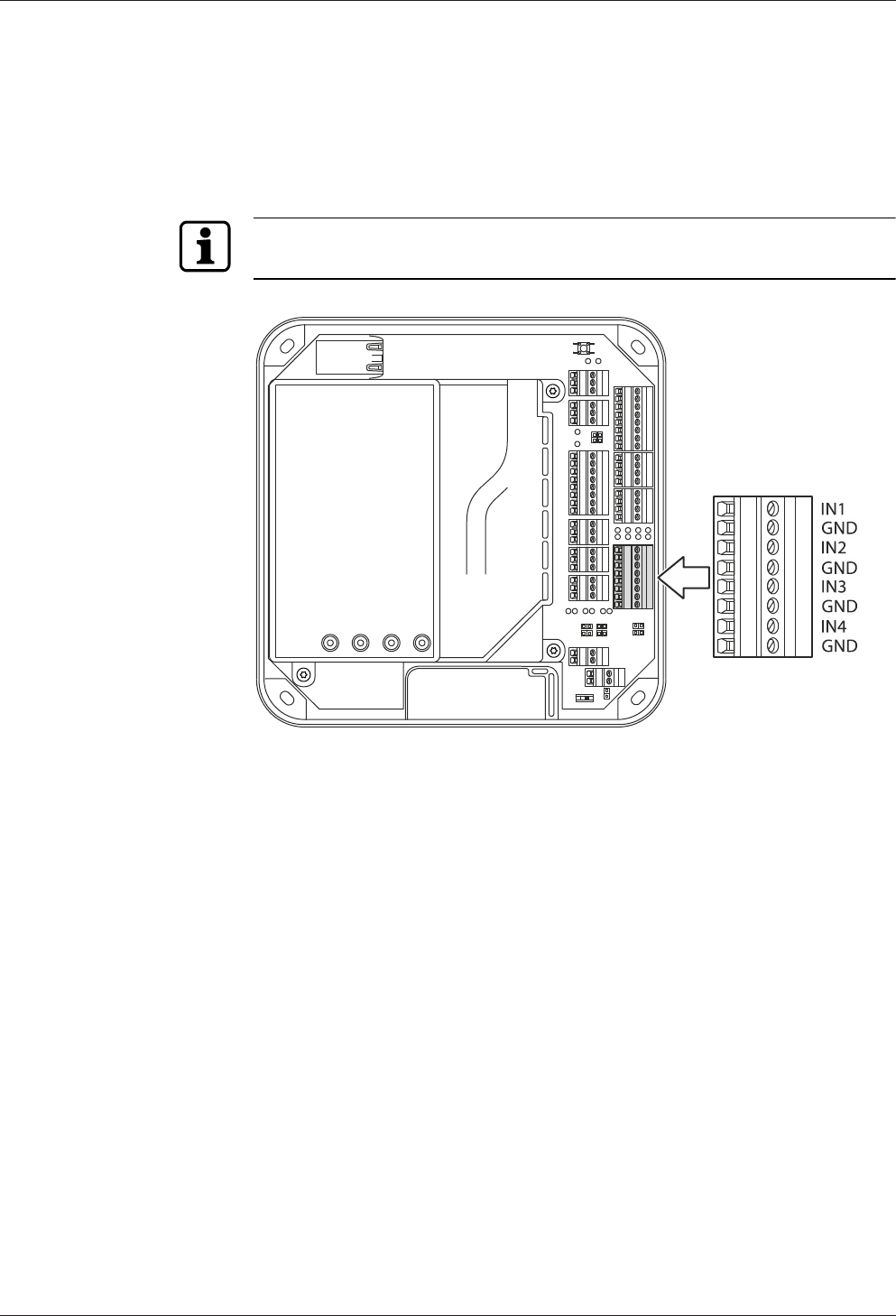
5.7.7 Inputs
The access manager has 4 inputs IN1 to IN4.
Function of the inputs
The inputs are used for the inquiry of sensors such as door-opener key, door handle
contact, door frame contact, bolt contact, vandal contact, pass-through contact (e.g.,
turnstile, light barrier), etc.
The function of the individual outputs depends on the settings of the terminal soft-
ware.
Principle
The inputs (IN1-IN4) are connected to GND using a simple switch or relay contact. An
open input is recognized as “high” due to the internal pull-up resistor. Ground poten-
tial equals “low.”
5.7.7.1 Line monitoring
The inputs can be designed as follows:
• Without line monitoring
• With line monitoring (if supported and activated by the terminal software)
Line monitoring allows the terminal software to detect the states short circuit and in-
terruption, in addition to the states active (input closed) and not active (input open)
and report them to the higher-level system.
The current states of the inputs are signaled by light emitting diodes [}5.7.7.5].
Installation Technical Manual
54 04045376 - 05/2016 Kaba access manager 92 30
5.7.7.2 Non-line-monitored inputs
Example: Connection to door frame contact not line-monitored.
Tampering to lines between access manager and door frame contact is not detected.
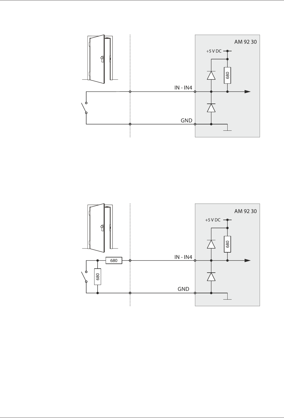
5.7.7.3 Line-monitored inputs
With line monitoring activated, resistors (680 Ω, 0.25 W, 2 %) must be connected in
series and in parallel to the respective contact. The resistors must be attached in a
vandal secure manner directly to the external contact.
Example: Connection to door frame contact line-monitored.
Tampering to lines between access manager and door frame contact is detected.
Technical Manual Installation
5504045376 - 05/2016Kaba access manager 92 30
5.7.7.4 Switching criteria
Function Contact State
Vandal contact open: Vandalism alarm
closed: Idle state
Door-opener key open: Idle state
closed: Door opener key pressed
Door frame contact open: Door open
closed: Door closed
Bolt contact open: Door unlocked
closed: Door locked
Entry contact open: Idle state
closed: Entry taken place
Door handle contact open: Idle state
closed: Door handle operated
Block access points open: Idle state
closed: All assigned access doors locked (all door-
opener relays drop out)
Release access points open: Idle state
closed: All assigned access doors released (all
door-opener relays are pulled-in, e.g.
emergency in case of fire)
The states described correspond to the default settings. Depending on the settings
of the terminal software, the states can also be interpreted inverted (see reference
manual of the terminal software).
Installation Technical Manual
56 04045376 - 05/2016 Kaba access manager 92 30
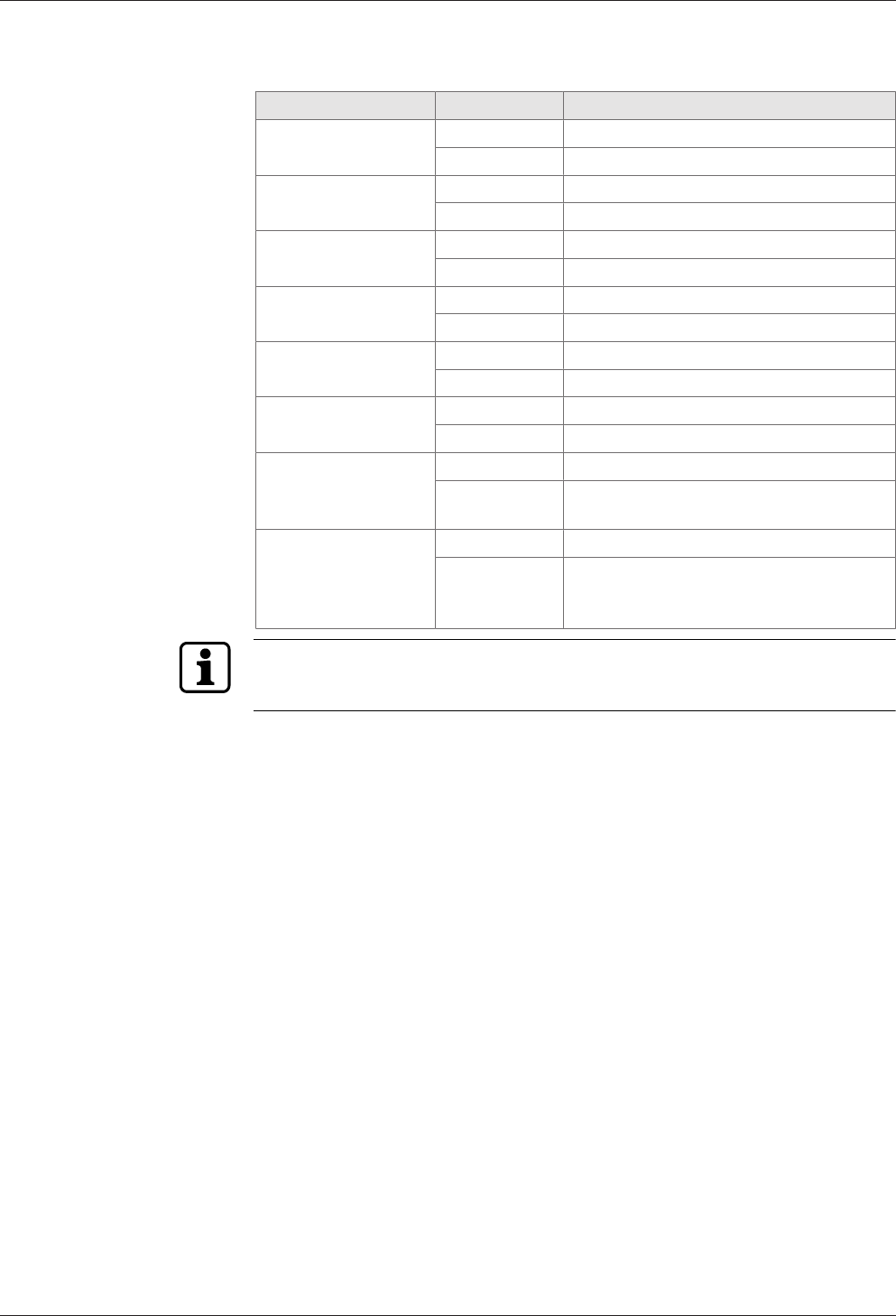
5.7.7.5 Status display
Above the terminal for the inputs, there are light emitting diodes for status display of
the inputs.
The current status of the inputs is indicated by a red and green LED respectively as
follows.
Designation Signal Meaning
IN1 - IN4 Off Input is not active (open)
lit green Input is active (closed)
red and green lit Short circuit*
red lit Interruption*
* only with active line monitoring
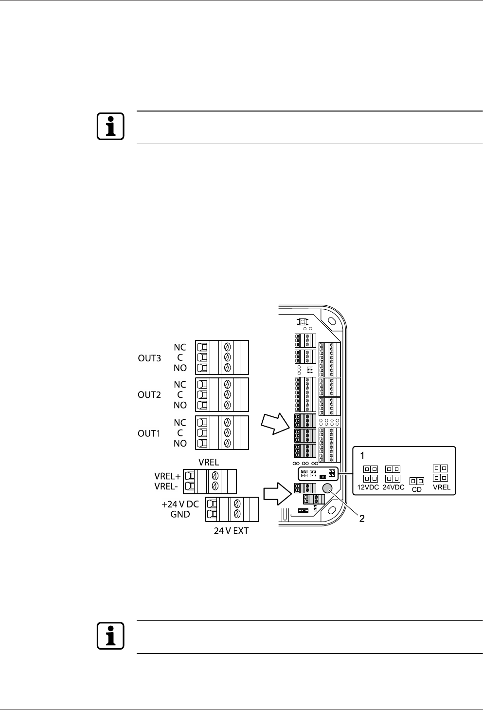
Technical Manual Installation
5704045376 - 05/2016Kaba access manager 92 30
5.7.8 Outputs
The access manager has 3 relay outputs OUT1 to OUT3.
Contact rating: 30 V AC/DC; 2 A max.
The outputs can be used for the activation of motor locks, door openers, turnstile
drives, technical alarm day/night, security alarm day/night etc.
The function of the individual outputs depends on the settings of the terminal soft-
ware.
The wiring of the output OUT1 can be adjusted via jumper (1). The following variants
are possible as an alternative:
• OUT1 is used as a potential-free contact
• The internal 12 V DC power supply is switched to the output OUT1.
• A DC power supply applied to the VREL terminal is switched to the output OUT1.
• The external 24 V DC power supply (24 V EXT terminal) is switched to the output
OUT1.
The outputs OUT2 and OUT3 are designed permanently as potential-free relay out-
puts with one switching contact each.
1 Jumper for the wiring of output OUT1
2 Fuse F1 for protection of the power supply via OUT1
Fuse value: T2.5 A
The fuse is plugged in and can be replaced without problems.
The fuse F1 may only be replaced with fuses of the same type.
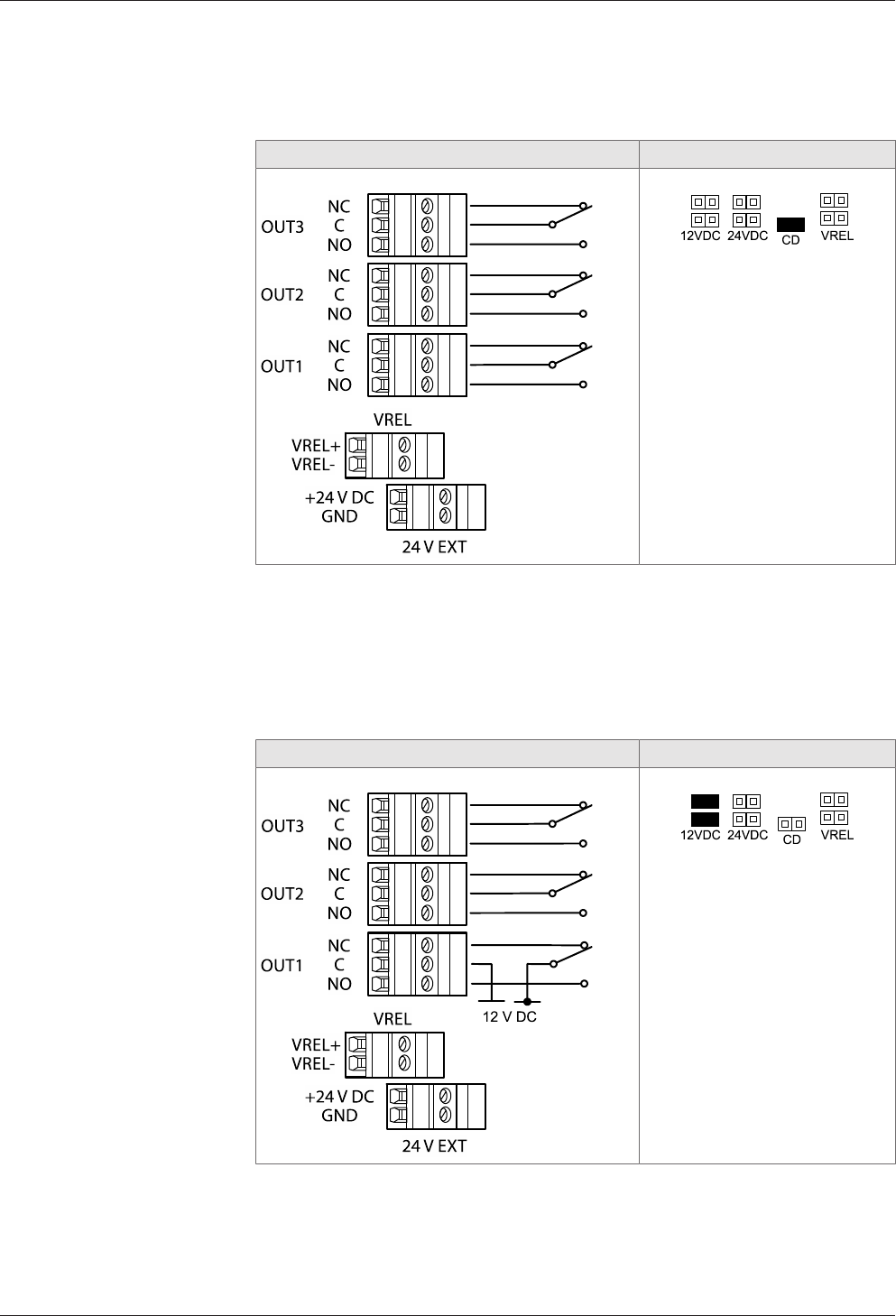
Installation Technical Manual
58 04045376 - 05/2016 Kaba access manager 92 30
5.7.8.1 OUT1 as potential-free switching contact
By setting the jumper with the designation CD, the OUT1 output can be used simi-
larly to the outputs OUT2 and OUT3 as potential-free switching contact.
Principle of output wiring Jumper position
IMPORTANT: Only the CD
jumper may be set. All other
jumpers may not be set.
5.7.8.2 Switching 12 V DC to OUT1
By setting the jumper with designation 12 V DC, the internal 12 V DC power supply is
switched to the OUT1 output. Consumers, for example door openers which are oper-
ated with 12 V DC can be directly connected to OUT1 in this way.
This variant can be used both with device power supply via PoE and device power
supply via an external 24 V DC power supply unit.
Principle of output wiring Jumper position
IMPORTANT: Only the jumper
pair 12 V DC may be set. All
other jumpers may not be set.
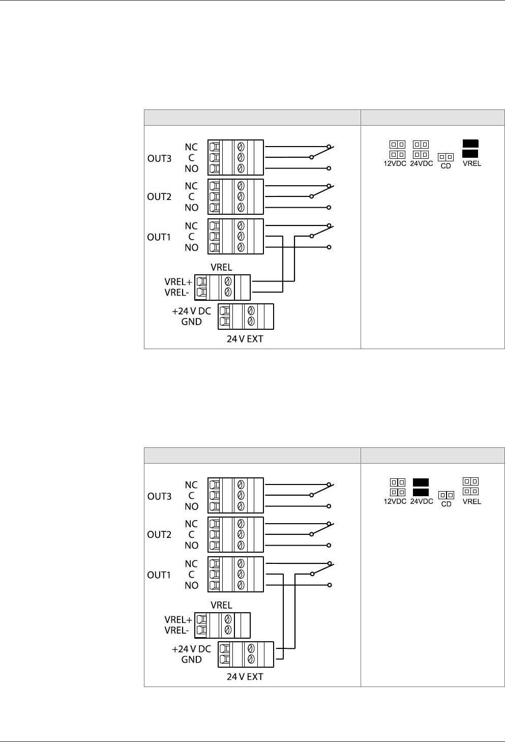
Technical Manual Installation
5904045376 - 05/2016Kaba access manager 92 30
5.7.8.3 Switching the external DC power supply to OUT1
By setting the jumper pair with designation VREL, a DC power supply connected via
the VREL terminal (max. 30 V DC, 2 A) is switched to the OUT1 output.
This variant can be used both with device power supply via PoE and device power
supply via an external 24 V DC power supply unit.
Principle of output wiring Jumper position
IMPORTANT: Only the jumper
pair VREL may be set. All other
jumpers may not be set.
5.7.8.4 Switching 24 V DC to OUT1
By setting the jumper pair with designation 24 V DC, the 24 V DC power supply (ter-
minal 24 V EXT) is switched to the OUT1 output. Consumers, for example door open-
ers which are operated with 24 V DC, can be directly connected to OUT1 in this way.
This variant can be used only with device power supply via an external 24 V DC
power supply unit. Not for power supply via PoE.
Principle of output wiring Jumper position
IMPORTANT: Only the jumper
pair 24 V DC may be set. All
other jumpers may not be set.
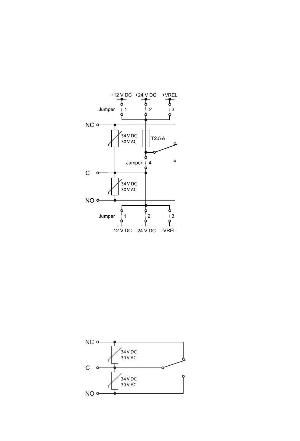
Installation Technical Manual
60 04045376 - 05/2016 Kaba access manager 92 30
5.7.8.5 Principle of output wiring
OUT1
The jumper pairs 1 - 3 are used to select the power supply which is switched directly
to the consumer via the relay output OUT1.
The power supply is protected by a fuse.
By setting the jumper 4 (designation CD), OUT1 can also be used as a potential-free
switching contact.
1 Switch the internal 12 V DC power supply to OUT1
2 Switch 24 V DC power supply (terminal 24 V EXT) to OUT1
3 Switch the external DC power supply (terminal VREL) to OUT1
4 Use OUT1 as potential-free switching contact
Only the jumpers may be set to a setting. I.e. jumper pair 1 or 2 or 3 or jumper 4.
OUT2 and OUT3
The outputs OUT2 and OUT3 are designed as potential-free relay outputs with one
switching contact each.
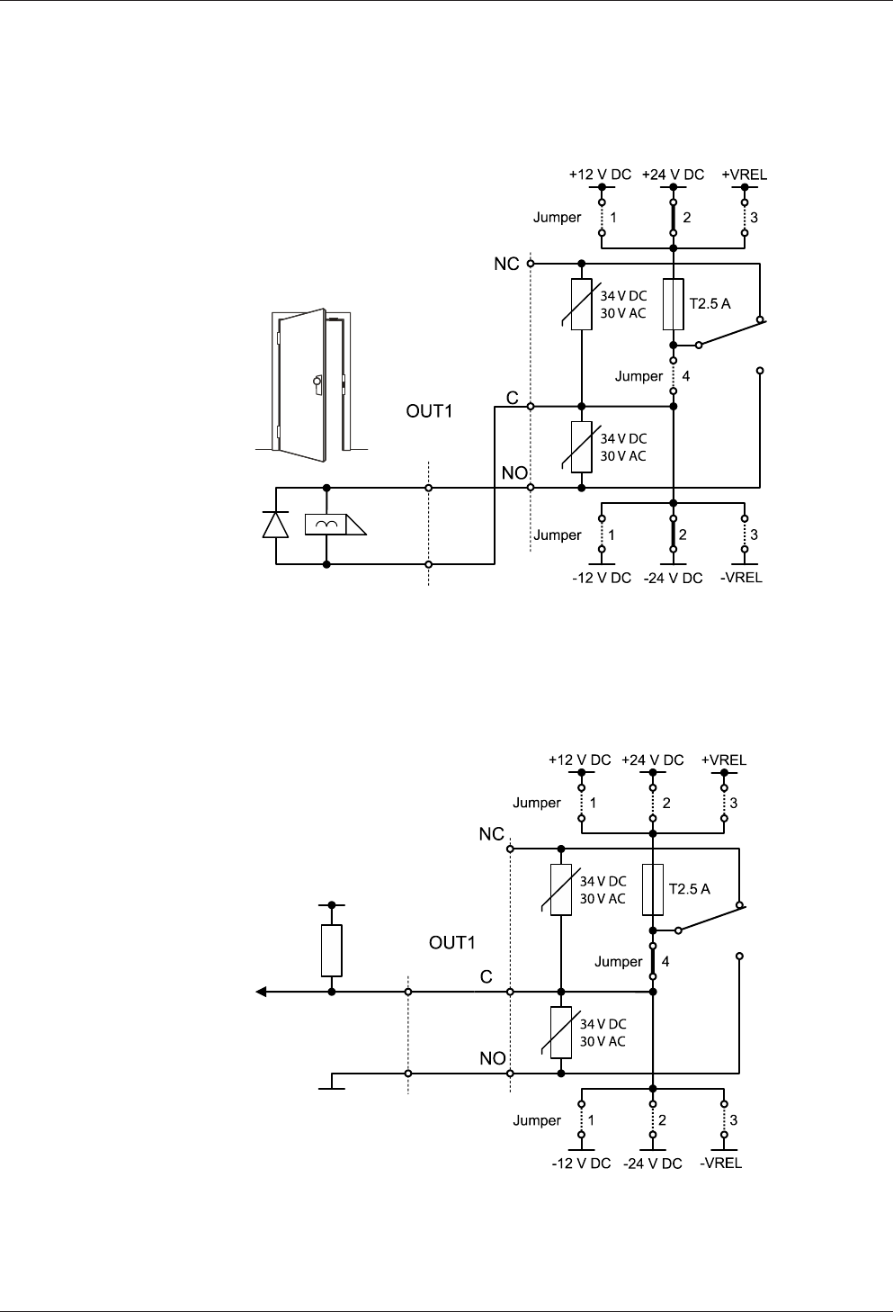
Technical Manual Installation
6104045376 - 05/2016Kaba access manager 92 30
5.7.8.6 Examples
Example 1
Connection of a door opener with 24 V DC power supply to OUT1.
Only jumper pair 2 is set. All other jumpers may not be set.
Example 2
Potential-free control of a digital input via OUT1.
Only jumper 4 is set. All other jumpers may not be set.
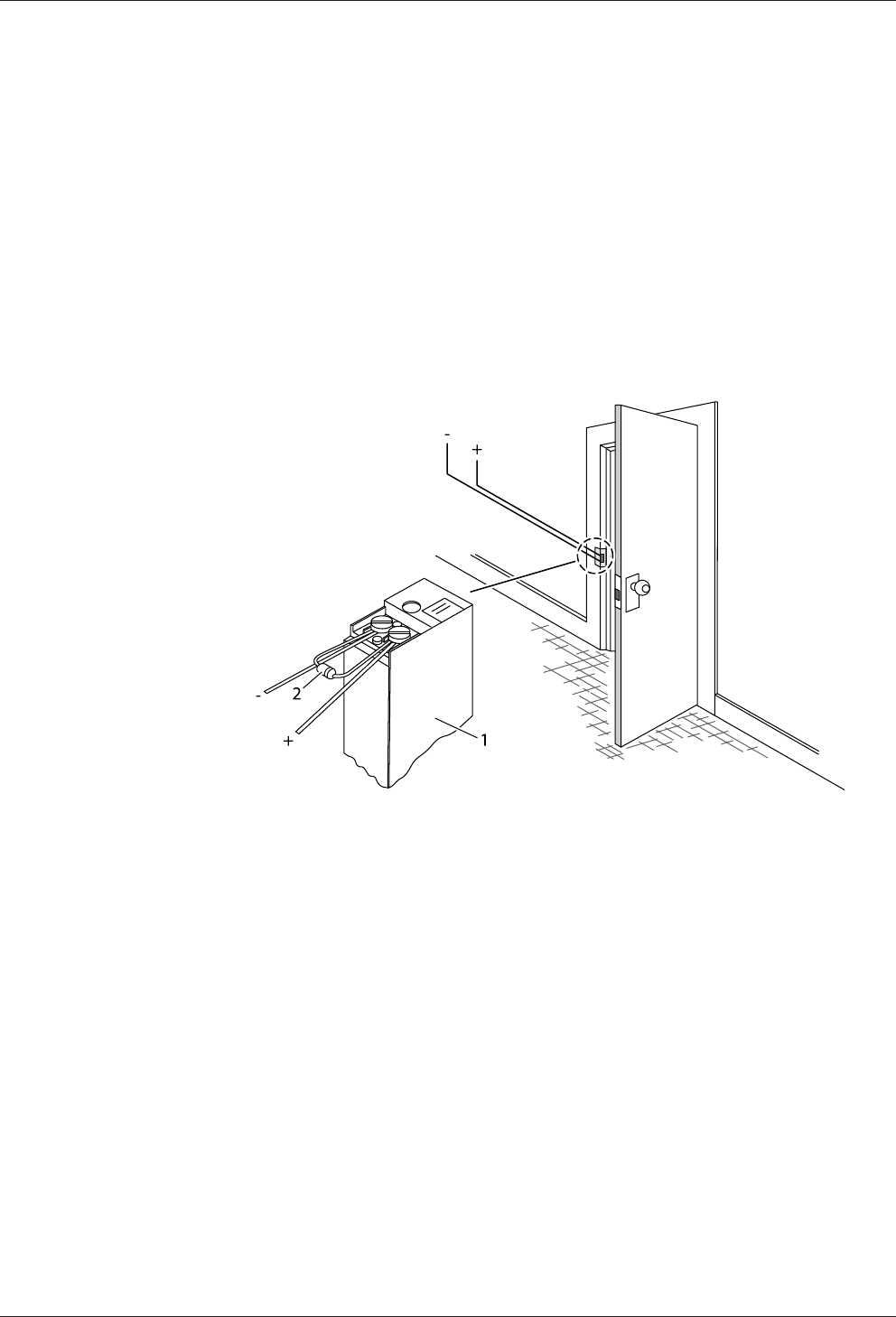
Installation Technical Manual
62 04045376 - 05/2016 Kaba access manager 92 30
5.7.8.7 Connecting door openers
Closed-circuit door-openers and open-circuit door-openers can be used.
For door openers that are supplied with DC voltage, a diode (a freewheeling diode)
must be connected in parallel to the door opener to suppress interference. In doing
so, make sure that the diode is connected in reverse-bias direction and check the po-
larity of the connected voltage.
When using an alternating voltage power supply, a varistor or a bipolar suppressor
diode must be connected in parallel. As regards the dimensioning and type, observe
the specifications of the door opener manufacturer.
The diode or varistor must be connected directly to the door opener and may not be
fitted to the access manager.
This step is not required if a door opener with internal varistor or diode is used.
1 Door-opener
2 Freewheeling diode or varistor
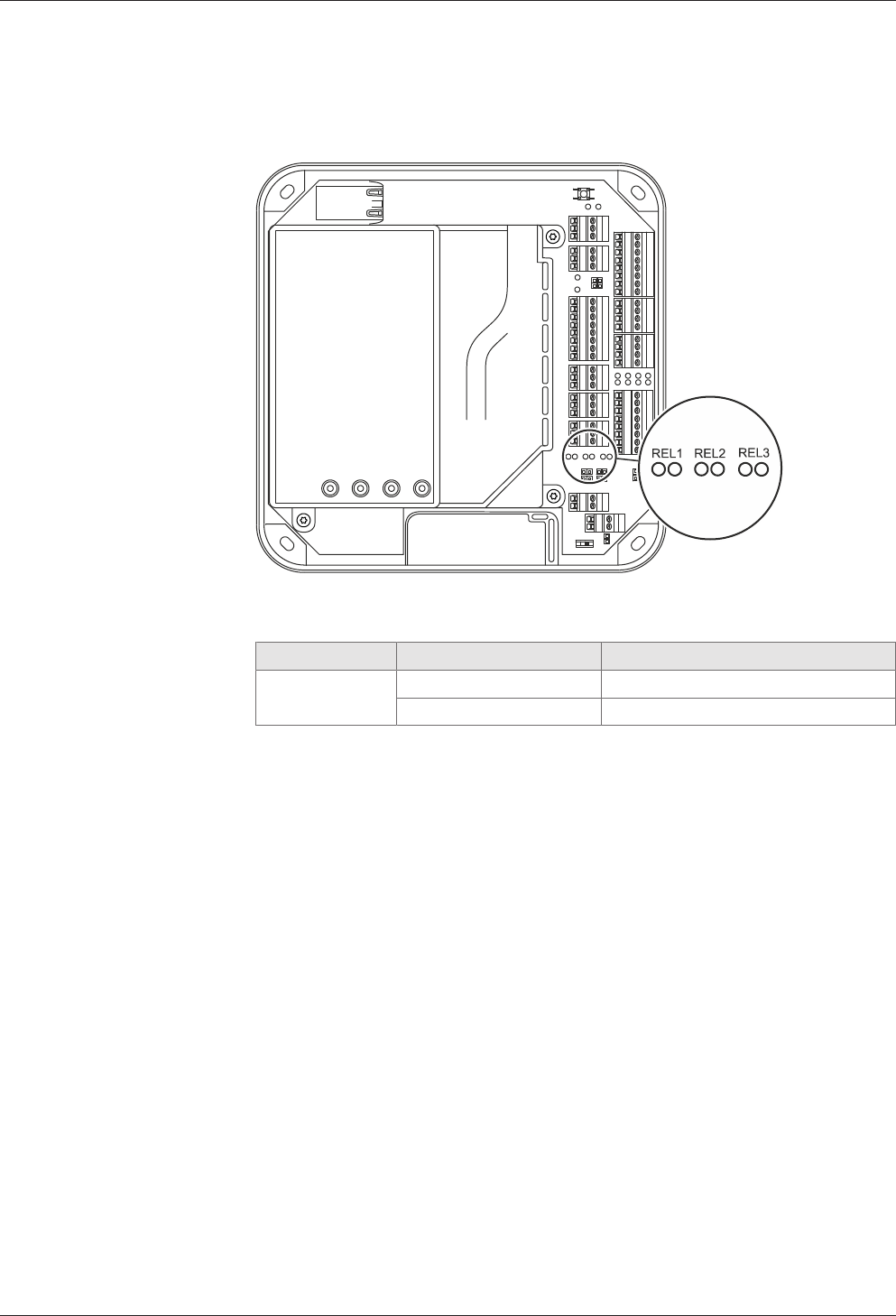
Technical Manual Installation
6304045376 - 05/2016Kaba access manager 92 30
5.7.8.8 Status display
Below the terminals for the outputs, there are light emitting diodes for status display
of the outputs.
The current status of the outputs is indicated as follows.
Designation Signal Meaning
REL1-3 Off Relay is not pulled-in
lit green Relay is pulled-in
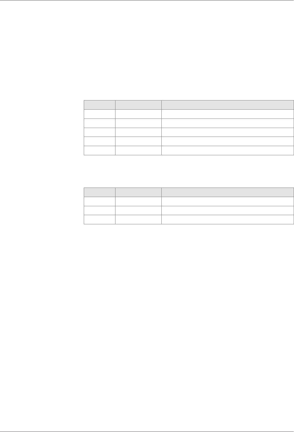
Installation Technical Manual
64 04045376 - 05/2016 Kaba access manager 92 30
5.7.9 Standard assignment of inputs/outputs (B-Client AC30)
The following assignment for the inputs and outputs has been preset for the B-
Client AC30 terminal software [}5.7.10.3].
The assignment of the functions can be adjusted in the b_client_ac30.ini configura-
tion file. Details on the configuration can be found in the B-Client AC30 reference
manual.
5.7.9.1 Inputs
The following functions are assigned by default to the inputs by the terminal soft-
ware.
Input Connection Function
BI01 IN1 Door frame contact 1
BI02 IN2 Door-opener key 1
BI03 IN3 Door frame contact 2
BI04 IN4 Door-opener key 2
BI36 IN5 Vandal contact
5.7.9.2 Outputs
The following functions are assigned by default to the outputs by the terminal soft-
ware.
Output Connection Function
BO01 OUT1 Door opener relay Door 1
BO02 OUT2 Door opener relay Door 2
BO20 OUT3 General alarm
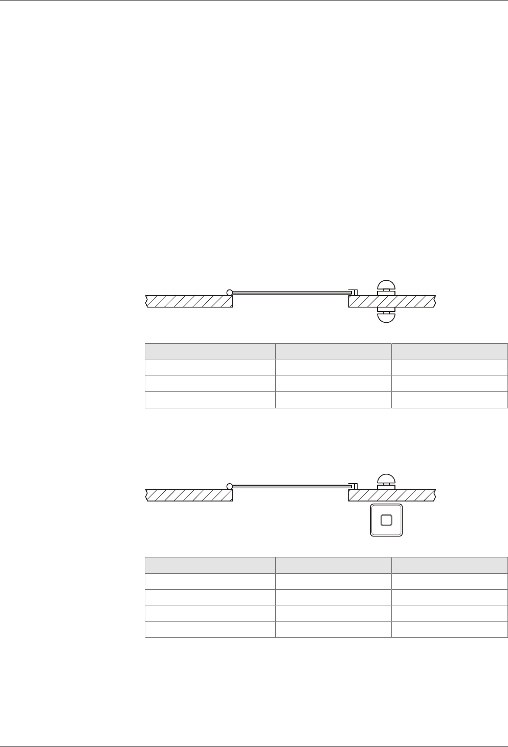
Technical Manual Installation
6504045376 - 05/2016Kaba access manager 92 30
5.7.10 Configuration-dependent assignment (B-Client AC30)
The B-Client AC30 terminal software provides 6 default configurations which can be
assigned via a door management parameter.
The configuration 2 (door-opener with 1 subterminal and 1 door-opener key) is the
preset default upon delivery.
Below, 5 configurations are listed which can be used due to a limited number of in-
puts and outputs of Kaba access manager 92 30.
The tables on the following pages show the assignment of inputs and outputs for the
corresponding configuration type.
5.7.10.1 Configuration 0: Subterminal without access
The inputs and outputs have no functions in this configuration. The logical group/de-
vice addresses 00/01 to 00/02 need to be set in the subterminals.
This configuration is recommended if the device is only used for time and atten-
dance.
5.7.10.2 Configuration 1: Door with 2 door opener keys
Access 1 2
Door frame contact IN1 IN3
Door opener key IN2 IN4
Door opener relay BO1 BO2
5.7.10.3 Configuration 2: Door with 1 subterminal and 1 door opener key
Access 1 2
Door frame contact IN1 IN3
Door opener key IN2 IN4
Door opener relay BO1 BO2
GID/DID 00/01 00/02
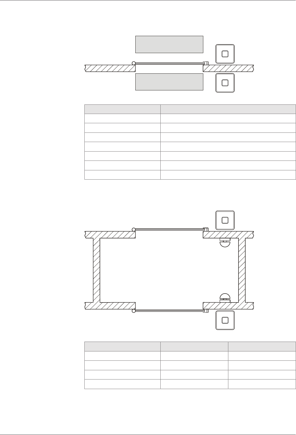
Installation Technical Manual
66 04045376 - 05/2016 Kaba access manager 92 30
5.7.10.4 Configuration 3: Door with 2 subterminals and contact mat, barrier, etc.
A
B
Access 1
Door frame contact IN1
Barrier IN2
Bolt contact IN3
Door opener relay BO1
Alarm relay BO2
GID/DID Subt. A 00/01
GID/DID Subt. B 00/02
5.7.10.5 Configuration 4: Sally port with 2 subterminals and 2 door opener keys
A
B
Access 1 A 1 B
Door frame contact IN1 IN3
Door opener key IN2 IN4
Door opener relay BO1 BO2
GID/DID 00/01 00/02
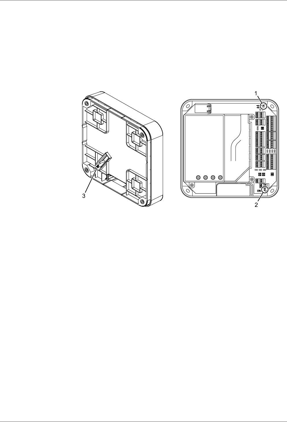
Technical Manual Installation
6704045376 - 05/2016Kaba access manager 92 30
5.8 Vandal contact
The device has two vandal contacts (tamper).
A switching contact (1) is opened if the housing cover is removed.
Another switching contact (3) is opened if the device is removed from the wall.
Switching contact (3) is deactivated by the jumper with designation TE- (2) in the de-
livery state. To activate the switching contact (3), the jumper TE- (2) must be re-
moved.
Opening of one or both switching contacts leads to the status indication of the inter-
nal input 5.
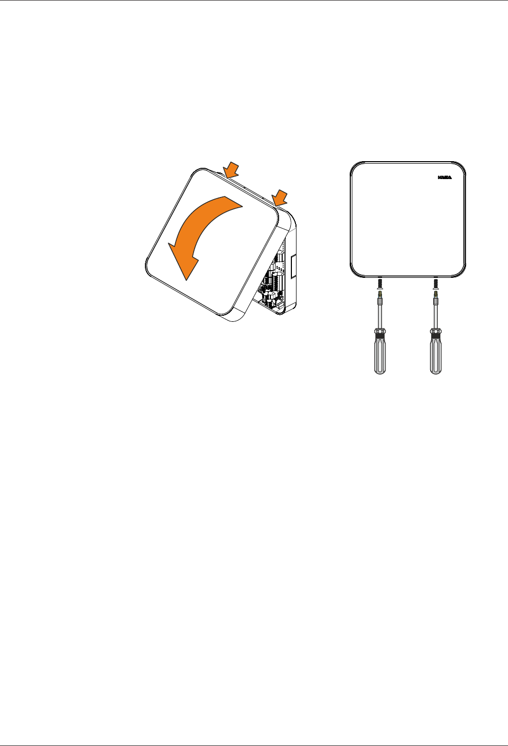
Installation Technical Manual
68 04045376 - 05/2016 Kaba access manager 92 30
5.9 Fastening the cover
Fasten the housing cover in the following way:
1. Hang the mounting lugs of the housing cover at the top of the bottom part of
the housing.
2. Pivot the housing cover down and close the housing.
3. Fasten the housing cover by means of two screws M3x8 (TORX 8) on the bottom
part of the housing.

Technical Manual Start-up
6904045376 - 05/2016Kaba access manager 92 30
6 Start-up
6.1 Network requirements
Start-up and communication in regular operation are done via an Ethernet network.
To guarantee unhindered and trouble-free data traffic, the UDP ports used for com-
munication must have been enabled.
The firewall configuration must therefore be adapted accordingly.
6.1.1 Communication
The UDP port used for communication between B-COMM and the terminal must
have been enabled.
The UDP port is in the range from 7700 hex. to 77EF hex. (30464 dec. to 30703 dec.),
depending on configuration.
6.1.2 Automatic registration via B-COMM
The network must have been equipped with a working DHCP server.
It must be possible to transfer UDP data packages unhindered to the B-COMM server.
• IP address 239.255.255.250, UDP port 1900 dec. and UDP port 7900 (30976dec.)
must have been enabled.
• The SSDP service has to be enabled in the Windows service management.
• The SFTP connection via the standard port 22 must have been enabled.
If the device does not receive an IP address because there is no DHCP server in the
network or the DHCP server does not answer, the device will assign an address to it-
self.
Auto IP addresses always have the format 169.254.x.y, with x and y being two ran-
dom numbers between 0 and 255.

Start-up Technical Manual
70 04045376 - 05/2016 Kaba access manager 92 30
6.2 Automatic registration via B-COMM
Start-up of the access manager takes place largely automatically in connection with
the B-COMM communication software.
The device is preset at the factory for automatic registration via B-COMM.
System requirements
• B-COMM communication software version 3.10 and higher.
• Network with a working DHCP server.
Start-up procedure
1. Connect the access manager to the network and switch it on.
ðAfter booting, the device cyclically reports to the B-COMMs active in the net-
work.
ðIn this status, the status LED lights up alternately 0.5 seconds in red and 0.5
seconds in green.
ðOnce the device is found by B-COMM, the relevant data that identifies the
device will be queried.
ðIf the device is not known, it will be entered in B-COMM under the
B-COMM Terminal Discovery client under BCTDS (Terminal Discovery
Stream).
2. If the device is to be managed via a B-COMM, it can be moved to the desired
stream and provided with the corresponding communication parameters.
ðAfter having assigned the device permanently to B-COMM, B-COMM first up-
dates the settings of the device and then makes a backup of the settings to-
gether with the “sop.ini” license file.
3. Transmitting specific parameters and master records to the device.
ðThe terminal software is automatically restarted, after which the device is
ready for use.
ðThe device now reports to the B-COMMs active in the network that registra-
tion has been carried out, after which the device will be removed again from
the BCTDS stream by the other B-COMMS.
ðThis concludes the automatic registration via B-COMM.

Technical Manual Start-up
7104045376 - 05/2016Kaba access manager 92 30
6.3 Start options
6.3.1 Performing a cold start
NOTICE
When performing a cold start, parameters are reset to their default values. Master
records and booking records are deleted.
Network settings as well as group and terminal addresses remain unchanged.
1. Turn off the device.
2. Turn on the device.
ðThe yellow status LED is lit.
ðAfter approx. 40 seconds, the yellow status LED starts flashing.
3. Within 10 seconds, press the reset key and keep it depressed.
ðThe status LED flashes faster for 5 seconds.
ðThe status LED lights up in green for 2 seconds.
ðA cold start was performed.
4. Release the reset key again.
ðThe status LED lights up in red for 5 seconds.
ðThe status LED is lit in green.
ðThe system is ready for use, a cold start was performed.

Start-up Technical Manual
72 04045376 - 05/2016 Kaba access manager 92 30
6.3.2 Perform a cold start and set the default IP address 123.0.0.2
When performing a cold start, parameters are reset to their default values. Master
records and booking records are deleted.
1. Turn off the device.
2. Turn on the device.
ðThe yellow status LED is lit.
ðAfter approx. 40 seconds, the yellow status LED starts flashing.
3. Within 10 seconds, press the reset key and keep it depressed.
ðThe status LED flashes faster for 5 seconds.
ðThe status LED lights up in green for 2 seconds.
ðA cold start was performed.
ðThe status LED lights up briefly in red and then flashes in red for 5seconds.
ðThe status LED flashes in green for 2 seconds.
ðThe default IP address 123.0.0.2 has been set.
4. Release the reset key again.
ðThe status LED is lit in green.
ðThe system is ready for use, a cold start was performed, and the default IP ad-
dress 123.0.0.2 was set.
6.3.3 Setting the default IP address 123.0.0.2 (without cold start)
1. Turn off the device.
2. Turn on the device.
ðThe yellow status LED is lit.
ðAfter approx. 40 seconds, the yellow status LED starts flashing.
ðAfter another 10 seconds, the red status LED is lit.
3. Within 5 seconds, press the reset key and keep it depressed.
ðThe status LED flashes faster for 5 seconds.
ðThe status LED flashes green for 2 seconds.
ðThe default IP address 123.0.0.2 has been set.
4. Release the reset key again.
ðThe green status LED is lit.
ðThe system is ready for use, the default IP address 123.0.0.2 was set.
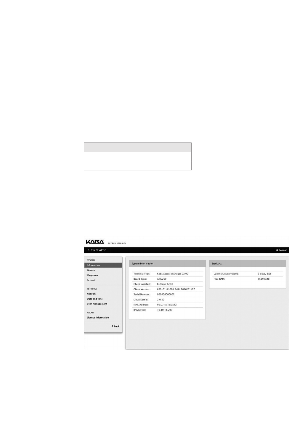
Technical Manual Start-up
7304045376 - 05/2016Kaba access manager 92 30
6.4 Service Interface
The device is provided with a service interface allowing you to make manual settings.
Access takes place via the network connection of the device, either directly or via the
network. For direct connection, an Ethernet cross-over cable (crossed RJ-45 cable) or
an Ethernet patch cable 1:1 can be used (Auto MDIX).
The service interface can be accessed from a service PC via web browser by typing
the device IP address into the address box. If the IP address of the device is not
known, you can either set the default IP address 123.0.0.2 or determine and assign
the IP address using the Device Discovery Tool [}6.5].
The Device Discovery Tool is always available for download on the Internet at the
Kaba site.
6.4.1 Login
User name and password are requested after selecting the service interface.
The following users are already defined by default:
User name Password
admin admin
root root
6.4.1.1 Changing passwords
For security reasons, the default password should be changed. After the login with
user "root", both passwords can be changed by means of the "User management"
function.
6.4.2 Basic structure
After successful login, you can use the service functions. Select the desired function
from the main menu on the left.

Start-up Technical Manual
74 04045376 - 05/2016 Kaba access manager 92 30
6.4.3 Overview of the service functions
SYSTEM Function Description
Information System Information Information on hardware and software
of the device and display of IP address
and MAC address
Statistics Time elapsed since last system start
License License Display of the current software license
Create temporary test
license
Creation of a temporary test license with
full functionality. This test license allows
you to use all options. It is valid for a du-
ration of 7 days and can be generated
five times.
Diagnosis Log overview Display/download of the log files
Reboot Reboot B-Client AC30 Restart access manager, in order to ac-
cept, for example, modified network set-
tings or to perform a cold start, see chap-
ter 6.3.1).
SETTINGS Function Description
Network Network Settings Settings for communication via the net-
work.
Host Settings Definition of the host computer
FTCS Settings Definition of the FTCS (Finger Template
Control Server).
These settings are required if the device
is equipped with a biometric reader.
CardLink Settings Definition of the CardLink host.
These settings are required if a separate
host is used to distribute the specific pa-
rameters and data records for CardLink.
Date and time Date and time Display and, if necessary, set date and
time.
User
management
Change user passwords Change the passwords for the “admin”
and “root” users
6.4.4 Actions within the service functions
Clearing input fields
• Click the Clear button.
Applying entries and closing the function
• Click the Submit button.
Canceling the function, discarding entries
• Click the Cancel button or select a different function from the menu.
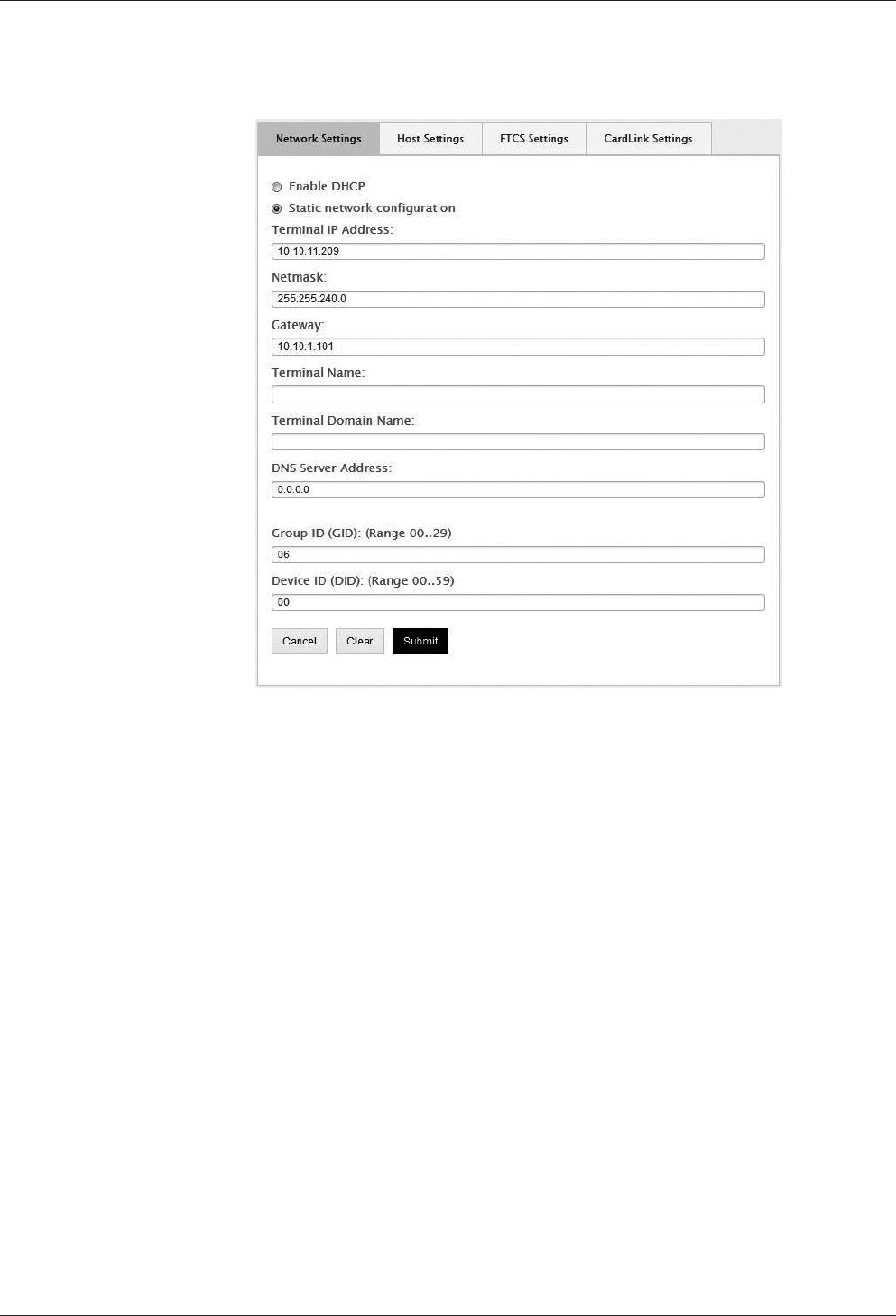
Technical Manual Start-up
7504045376 - 05/2016Kaba access manager 92 30
6.4.5 Network settings
Function call: Menu > SETTINGS > Network > Network Settings
Getting an IP address from the DHCP server
1. Tick “Enable DHCP”.
2. Enter the IP address of the DNS server in the “DNS Server Address” input field. En-
ter 0.0.0.0 if no DNS server is to be used in the network.
Requesting the IP address from the DHCP server on the basis of the terminal
name
1. Tick “Enable DHCP”.
2. Enter the “Terminal Name” and “Terminal Domain Name” according to RFC 1123.
3. Enter the IP address of the DNS server in the “DNS Server Address” input field. En-
ter 0.0.0.0 if no DNS server is to be used in the network.
Assigning a permanent IP address
1. Enable “Static network configuration”.
2. Enter the desired IP address of the device in the “Terminal IP Address” input field.
3. Enter the netmask in the “Netmask” input field.
4. If the device and the host PC are in different network segments, you will have to
enter the gateway IP address that connects the network segments in the “Gate-
way IP address” input field. Enter 0.0.0.0 if no gateway is available.
5. Enter the IP address of the DNS server in the “DNS Server Address” input field. En-
ter 0.0.0.0 if no DNS server is to be used in the network.

Start-up Technical Manual
76 04045376 - 05/2016 Kaba access manager 92 30
Group identification and device identification
The group and device identifications are used to address a device. This identification
is part of each parameter record and each data record.
1. Enter the group identification in the “Group ID (GID)” input field.
2. Enter the device identification in the “Device ID (GID)” input field.
Value range: GID: 00 to 29, DID: 00 to 59.
In combination with the communication software B-COMM, the following must be
observed when assigning the device identification DID.
The device identifications must be assigned step-by-step for devices with connected
subterminals. The device identifications in between are reserved for subterminals.
• Assign the device identifications for terminals with up to 4 subterminals in steps
of 5, that is, 0/5/10/15, etc.
• Assign the device identifications for the access manager with up to 8 subtermi-
nals in steps of 10, that is, 0/10/20, etc.
• Assign the device identifications for the access manager with up to 16 subtermi-
nals in steps of 20, that is, 0/20/40, etc.
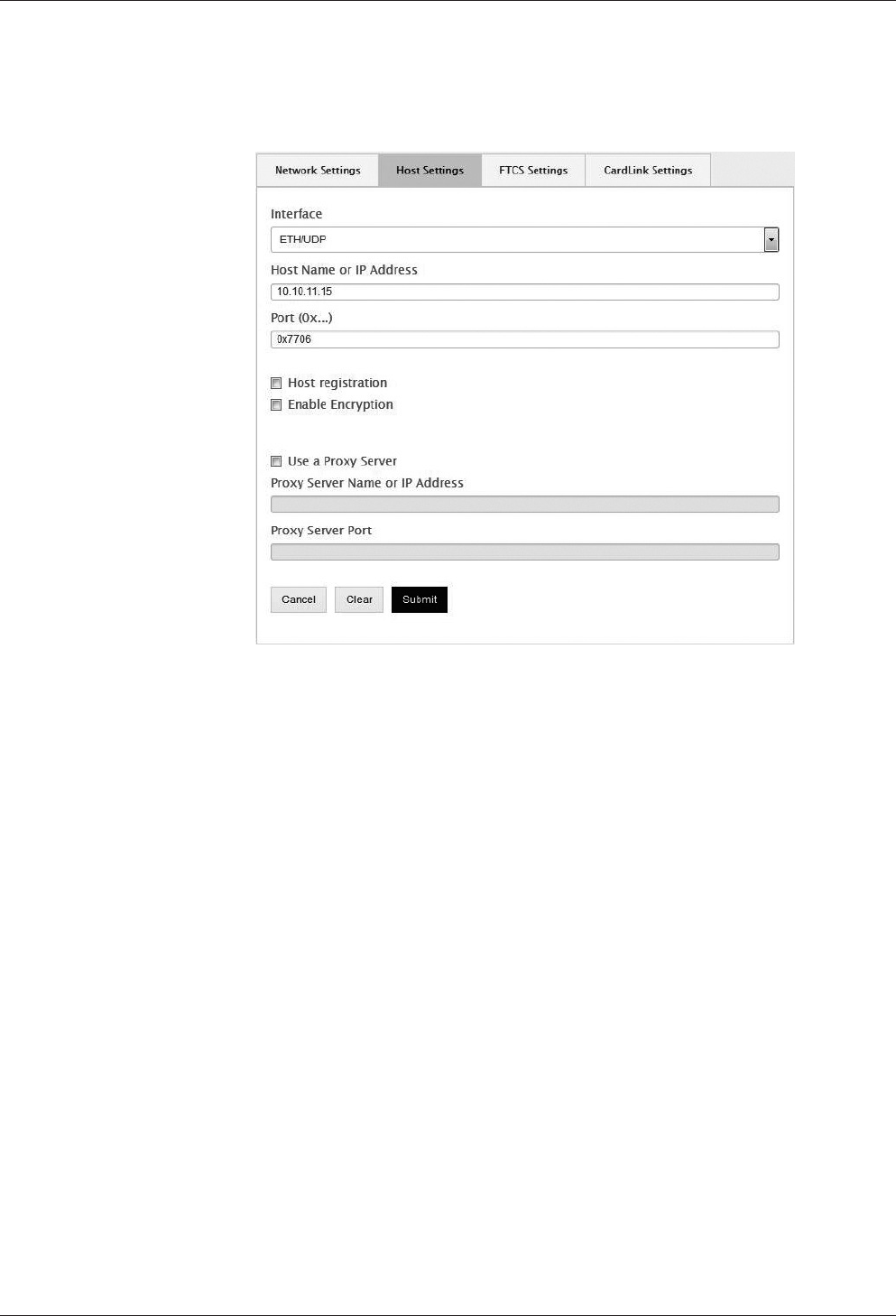
Technical Manual Start-up
7704045376 - 05/2016Kaba access manager 92 30
6.4.6 Host settings
Setting of the communication type and definition of the host computer.
Function call: Menu > SETTINGS > Network > Host Settings
Communication via Ethernet / UDP
This is the standard communication type
1. Set the “ETH/UDP” interface.
2. Enter the IP address of the computer communicating with the terminal software
in the “Host name or IP address” field. If a DNS has been configured, it is also pos-
sible to specify the host name in this field.
3. In the “Port” field, select the UDP port used for communication. It is specified in
hexadecimal format. Possible values are 7700 to 77EF.
Communication via Ethernet / XML
This communication type is a precondition for HTTP/HTTPS-based applications that
are used directly as communication software instead of B-COMM.
1. Set the "ETH/XML" interface.
2. Enter the IP address of the computer communicating with the terminal software
in the “Host name or IP address” field. If a DNS has been configured, it is also pos-
sible to specify the host name in this field.
3. In the “Port” field, select the UDP port used for communication. It is specified in
hexadecimal format. Possible values are 7700 to 77EF.
Automatic registration
This function allows the device to be operated almost automatically. The device re-
ports cyclically to the active B-COMMs in the network and is then registered [}6.2]
by them.
The function can be enabled or disabled by means of the "Host Registration" check
box.

Start-up Technical Manual
78 04045376 - 05/2016 Kaba access manager 92 30
Encryption
The “Enable encryption” check box is used to enable and disable the encryption via
Ethernet.
A license is required for this function.
Proxy server
If a proxy server is used:
1. Enable “Use a Proxy Server”.
2. Enter the proxy server name or IP address and the port.
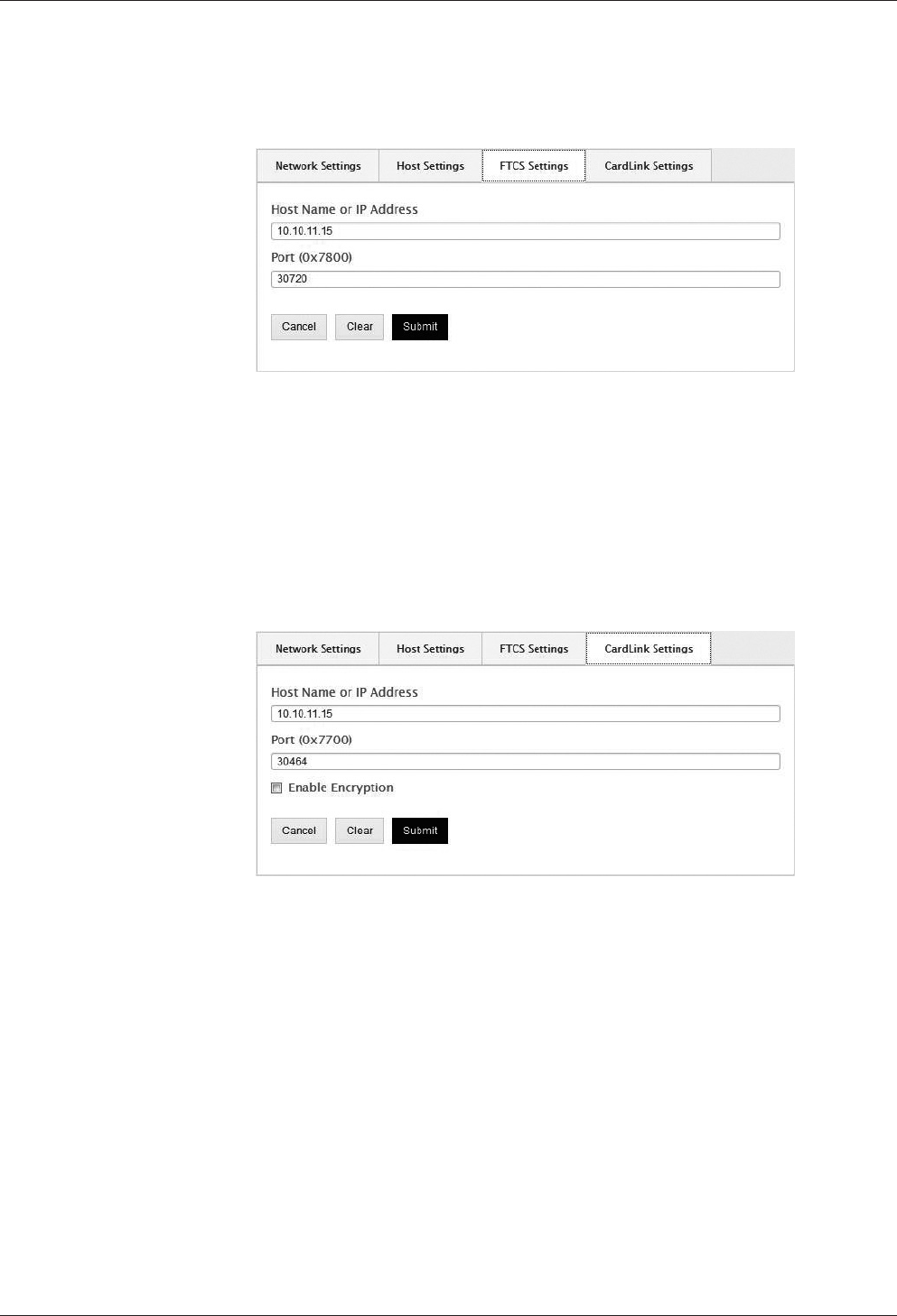
Technical Manual Start-up
7904045376 - 05/2016Kaba access manager 92 30
6.4.7 FTCS host settings
Definition of the FTCS (Finger Template Control Server).
Function call: Menu > SETTINGS > Network > FTCS Settings
These settings are required if subterminals with biometric readers are connected. The
settings are only required if the FTCS service is provided by a separate host server.
1. Enter the IP address of the computer on which the FTCS service is running (B-
COMM server). If a DNS has been configured, it is also possible to specify the
FTCS host name in this field.
2. Select the UDP port used for communication in the “Port” field, default=7800.
6.4.8 CardLink host settings
Definition of the CardLink host.
Function call: Menu > SETTINGS > Network > CardLink Settings
These settings are required if a separate host is used to distribute the specific param-
eters and data records for CardLink.
1. Enter the IP address of the host that provides the CardLink data. If a DNS has
been configured, it is also possible to specify the CardLink host name in this field.
2. Select the UDP port used for communication in the “Port” field, default=7700.
Encryption
The UDP encryption function is optional. A license is required for this function.
The “Enable encryption” check box is used to enable and disable the encryption via
Ethernet UDP.
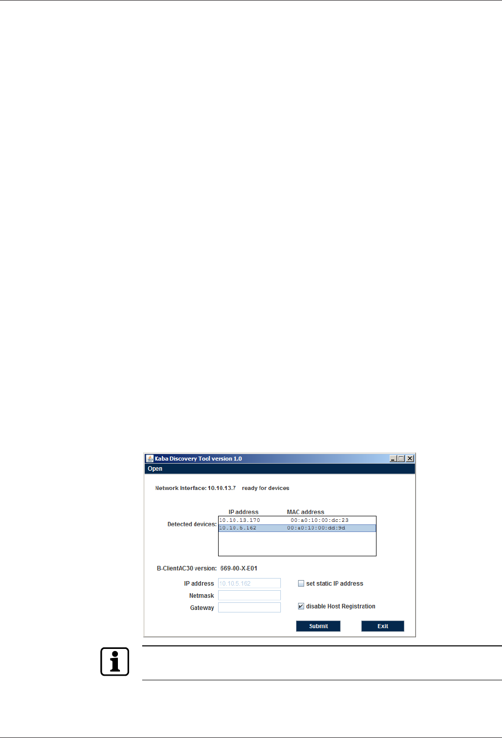
Start-up Technical Manual
80 04045376 - 05/2016 Kaba access manager 92 30
6.5 Device Discovery Tool
The Device Discovery Tool allows a manual device start-up without automatic regis-
tration via B-COMM.
The Device Discovery Tool is started on a service PC. It detects any devices available
in the network which wait for the host registration using the B-Client AC30 terminal
software and displays them.
After selecting a device, the network parameters can be adjusted.
6.5.1 System requirements
The program is an executable Java archive (.jar) JavaRuntime (JRE) from version 1.4
installed is required to execute the program.
Thus the program is executable on any computer system for which Java is available.
The device sends SSDP multicasts via address 239.255.255.250 to port 1900. A fire-
wall must be configured in such a way that these messages are not blocked. This re-
striction does not apply to the same network segment or a direct connection.
6.5.2 Selecting the network interface
After starting the Device Discovery Tool you first have to select the network interface
of the service PC.
1. Start the Device Discovery Tool.
2. Execute the "Open" menu item.
ðAny available network interfaces of the service PC are listed.
3. Select the network interface connected with the network which is used to com-
municate with the device in question.
6.5.3 Displaying devices with B-Client AC30
The program will now wait for SSDP packages from devices with B-Client AC30.
If a device is detected, its IP address and MAC address will be shown in the list.
This process may take up to one minute!
Physical assignment of a device is made via the MAC address.
It is affixed to and visible on/in every device (CPU).
Technical Manual Start-up
8104045376 - 05/2016Kaba access manager 92 30
6.5.4 Changing network parameters
After selecting a device in the list, the current version of the installed terminal soft-
ware is additionally indicated.
Furthermore the network parameters are displayed. IP address, net mask and gate-
way can be changed, if required.
Assigning a new IP address and disabling the host registration
1. Select the device to be changed in the list.
2. Enable the "Set static IP address" check box.
ðThe input fields are active.
3. Enter IP address and net mask.
4. Enter gateway. Enter "0.0.0.0" if no gateway is to be set or leave the field blank.
5. Leave the "Disable Host Registration" check box enabled.
6. Click the “Submit” button.
ðThe selected device applies the settings and executes a restart with disabled host
registration.
When changing network settings please make sure that the values are entered cor-
rectly in the fields. Invalid values are not applied by "Submit" and a corresponding
message is output.
The device does not send feedback to the Device Discovery Tool. After clicking the
"Submit" button you can exit the program.
Disabling host registration and maintaining network parameters
1. Leave the "Disable Host Registration" check box enabled.
2. Leave the "Set static IP address" check box disabled.
3. Click the “Submit” button.
ðThe selected device executes a restart with disabled host registration.
Irrespective of any previously entered values the device network settings are not
changed.
Do not make any changes, since host registration is supposed to remain
enabled
1. Click the “Exit” button.
ðThe program is closed.
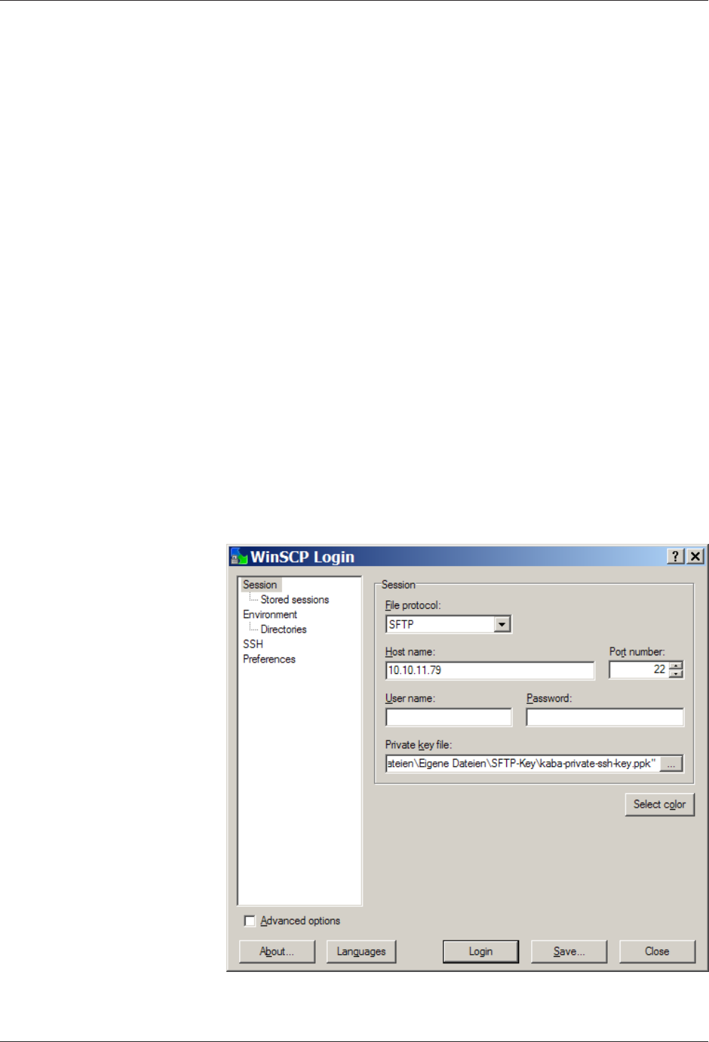
Start-up Technical Manual
82 04045376 - 05/2016 Kaba access manager 92 30
6.6 SFTP server
The device provides an SFTP server for a secure, encrypted connection via the “Se-
cure File Transfer Protocol” (SFTP).
6.6.1 Prerequisites
For the SFTP to access the terminal, the following is required:
• SFTP client, for example WinSCP. WinSCP (Windows Secure CoPy) is a free “open
source” SFTP and FTP client for Microsoft Windows.
• Kaba key file. The standard Kaba key file is always available for download on the
Internet at the Kaba site in the secured area.
• The SFTP connection via the standard port 22 must have been enabled.
6.6.2 Establishing an SFTP connection
After installation and start of the SFTP client, the login window appears.
Required settings:
File protocol: SFTP
Host name: <IP address> e.g. 10.10.11.79
Port number 22
User name: admin
Password: leave blank
Private key file: Select Kaba key file on local computer.
1. Make the following entries and settings
2. Click “Login”
.
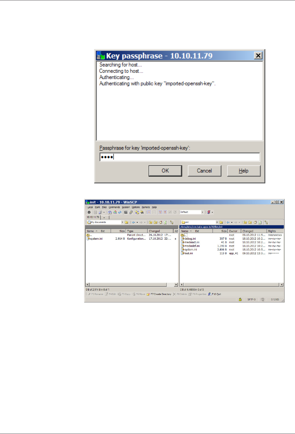
Technical Manual Start-up
8304045376 - 05/2016Kaba access manager 92 30
3. Enter pass phrase.
Pass phrase for standard Kaba key = kaba
4. Click "OK"
ðThe connection to the terminal is being established.
Packaging/Return Technical Manual
84 04045376 - 05/2016 Kaba access manager 92 30
7 Packaging/Return
Incorrectly packaged assemblies and devices may cause expenses due to damage
during transport.
Please observe the following information when sending Kaba products.
Kaba shall not be liable for damage to products which can be attributed to insuffi-
cient packaging.
7.1 Complete Devices
The original packaging is specially adapted for the device. It offers the greatest possi-
ble protection against transport damage.
Always use the original packaging for returns.
If this is not possible, then ensure the packaging prevents damage to the device.
• Use a stable, thick-walled transport crate or a box. The transport crate should be
large enough that there is 8–10cm space between the device and the container
wall.
• Wrap the device in suitable film or put in a bag.
• Pad generously around the device e.g. using foam padding or bubble wrap. It
must be ensured that the device does not move within the packaging.
• Only use dust-free environmentally-friendly filling material.
7.2 Electronic Assemblies
Electronic assemblies sensitive to ESD, such as circuit boards, readers, etc., must be
stored, transported and sent in suitable ESD protective packaging. The packaging of
electronic assemblies may only be carried out in ESD-protected workplaces by per-
sons who are familiar with and follow the general ESD protective regulations.
The return of electronic assemblies in packaging with sufficient ESD protection is a
condition for
• making guarantee claims in the event of malfunctions of any kind.
• replacement delivery of electronic circuit boards and components when an ex-
change is provided.
In order to guarantee a high quality standard, electronic components supplied in
packaging without sufficient ESD protection will be neither analyzed nor repaired,
but instead disposed of directly.

Technical Manual Packaging/Return
8504045376 - 05/2016Kaba access manager 92 30
7.3 Marking
Complete return papers and correct labeling allow us to process matters quickly.
Please ensure that a delivery note is included with the package. The delivery note
should include the following information:
• Number of devices or components per package.
• Item numbers, serial numbers, designations.
• Address of your company/contact.
• Reason for the return, e.g. repair exchange.
• Informative description of the fault.
In the event of returns from outside of the EU, a customs invoice with the real cus-
toms value will also be required. In some countries (e.g. Switzerland) a preference will
be required.

Disposal Technical Manual
86 04045376 - 05/2016 Kaba access manager 92 30
8 Disposal
This product meets the requirements of the WEEE Directive and, in accordance with
DIN standard EN 50419, is labeled with the WEEE crossed-out garbage can symbol.
The symbol indicates the separate disposal of electric and electronic equipment in
EU countries.
Do not dispose of the device with household waste under any circumstances.
Used devices contain valuable recyclable materials that should be recycled. Used de-
vices should therefore be disposed of via the collection system used in your country.
Disposal in Germany:
After use, Kaba GmbH undertakes to carry out the proper disposal of the supplied
goods in line with legal requirements (such as the ElektroG law in Germany). All costs
incurred for the transport of goods to the manufacturer's plant will be borne by the
owner of the used electronic equipment.
Disposal in Switzerland:
Send the device to an electronic equipment collection facility as per the VREG regula-
tion.
In the EU, electrical devices should be disposed of in accordance with national waste
disposal and environmental directives.
The erasure of personal data before disposal must be carried out self-dependent.
Dispose of packaging in an environmentally-friendly manner.
The packaging materials are recyclable. Please do not put the packaging in with
household waste, instead dispose of with waste for recycling.
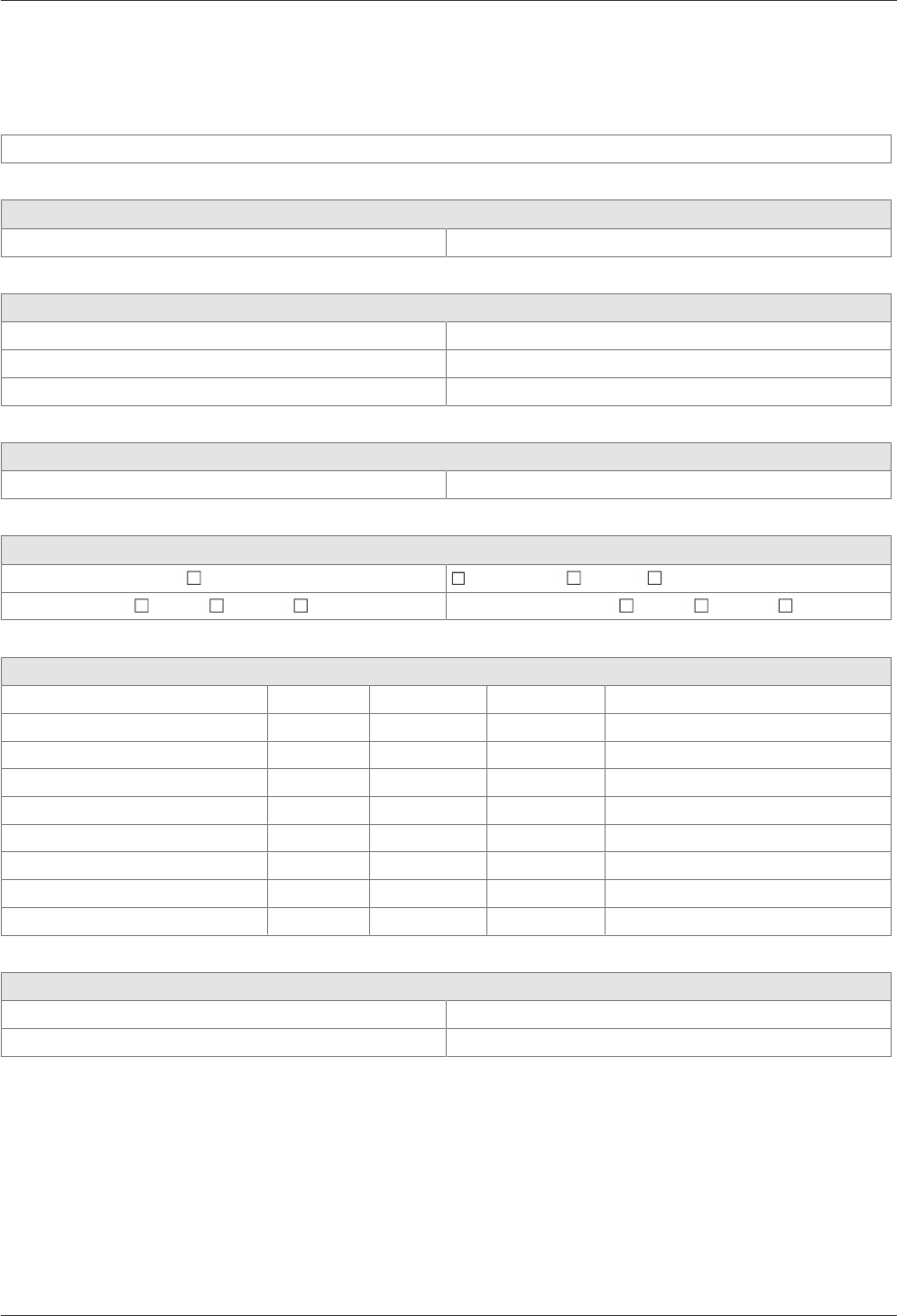
Technical Manual Appendix
8704045376 - 05/2016Kaba access manager 92 30
9 Appendix
9.1 Configuration Kaba Access Manager 92 30
Customer/Site:
Commissioning by
Name/company: Date:
TCP/IP settings
MAC address: IP address:
Host IP: Gateway IP:
Netmask: UDP Port:
Device settings
GID/DID: B-Client AC30 version:
Software license
Readers/subterminals 2 Encryption AVISO CardLink
Master records 2,000 10,000 50,000 Registration records 8,000 40,000 100,000
Readers/subterminals
Location Address Inputs Outputs Remark
Backup data directory + sop.ini
Performed: Date:
Backup stored with: Phone:

Appendix Technical Manual
88 04045376 - 05/2016 Kaba access manager 92 30
Index
Numerical
24 V DC input.............................................................................. 17
A
Alarm relay................................................................................... 27
Ambient conditions.................................................................. 20
Ambient temperature.............................................................. 20
Automatic registration via B-COMM .................................. 70
Autonomous............................................................................... 28
AVISO............................................................................................. 14
B
B-Client AC30 terminal software ......................................... 14
Bolt contact ................................................................................. 27
Bus termination ......................................................................... 50
C
Cable entry .................................................................................. 37
CardLink........................................................................................ 14
CardLink host settings............................................................. 79
CardLink update records ........................................................ 14
CardLink validation records................................................... 14
CE conformity ............................................................................. 21
Coaxial cable............................................................................... 41
Cold start ...................................................................................... 71
Conformity................................................................................... 21
D
Data encryption ......................................................................... 14
Default IP address ..................................................................... 72
Designated use .......................................................................... 10
Device Discovery Tool ............................................................. 80
Device status............................................................................... 35
Device variants........................................................................... 13
DHCP.............................................................................................. 70
DHCP server ................................................................................ 75
DID.................................................................................................. 76
Digital inputs .............................................................................. 18
Dimensional drawings............................................................. 20
Dimensions.................................................................................. 20
Disposal ........................................................................................ 86
DNS server ................................................................................... 75
Door frame contact .................................................................. 27
Door handle contact ................................................................ 27
Door opener key........................................................................ 27
Door-opener ............................................................................... 62
Door-opener relay..................................................................... 27
E
Electromagnetic fields............................................................. 36
ESD protective measures........................................................ 11
Ethernet interface ..................................................................... 19
Ethernet LED ............................................................................... 34
Ethernet receptacle .................................................................. 45
External power supply unit.................................................... 17
F
Fast online.................................................................................... 28
Fastening dimension ............................................................... 42
Fastening the cover.................................................................. 68
FTCS host settings..................................................................... 79
Function of the inputs............................................................. 27
Function of the outputs.......................................................... 27
Functional principle ................................................................. 24
G
GID:................................................................................................. 76
Group identification and device identification .............. 76
Grouped safety messages...................................................... 10
H
HF-RFID ......................................................................................... 19
Hole pattern ................................................................................ 42
Host settings ............................................................................... 77
HTTP/HTTPS ................................................................................ 77
I
Identification plate ................................................................... 22
Ingress protection..................................................................... 20
Inputs.......................................................................................18, 53
Inputs - Function ....................................................................... 27
Installation lines......................................................................... 41
Installation scheme......................................................38, 39, 40
Interfaces...................................................................................... 19
IP address ..................................................................................... 75
J
Jumper bus termination ......................................................... 50
L
Labeling ........................................................................................ 22
LEDs Inputs.................................................................................. 56
LEDs Outputs .............................................................................. 63
License file ................................................................................... 14
Light emitting diodes .............................................................. 34
Light emitting diodes RS-485 ............................................... 51
Limited power source.............................................................. 17
Line lengths................................................................................. 49
Line monitoring ......................................................................... 53
M
MAC address ............................................................................... 22
Master line ................................................................................... 49
Master records............................................................................ 14
Memory options ........................................................................ 14
N
Network cable ............................................................................ 41
Network connection ................................................................ 45
Network requirements ............................................................ 69
Network settings ....................................................................... 75
Number of subterminals......................................................... 14

Technical Manual
8904045376 - 05/2016Kaba access manager 92 30
O
Offline operating state ............................................................ 28
Online operating state ............................................................ 28
Operating states ........................................................................ 28
Output voltages......................................................................... 17
Outputs...................................................................................18, 57
P
Packaging..................................................................................... 84
Pass through ............................................................................... 27
PoE (Power over Ethernet)..................................................... 17
PoE switch.................................................................................... 44
Power LED.................................................................................... 34
Power supply .............................................................................. 17
Power supply of the subterminals ...................................... 15
Power supply unit ..................................................................... 17
Proxy server................................................................................. 78
R
R&TTE Directive................................................................ 21
Reader ........................................................................................... 19
Reader interface......................................................................... 13
Readers.......................................................................................... 26
Registration records ................................................................. 14
Registration unit ..................................................................26, 48
Relative humidity ...................................................................... 20
Relay outputs........................................................................18, 57
Return............................................................................................ 84
RFID standard ............................................................................. 19
RoHS............................................................................................... 21
RS-232............................................................................................ 19
RS-485............................................................................................ 19
RS-485 bus termination .......................................................... 50
RS-485 interface......................................................................... 49
RS-485 LEDs................................................................................. 51
S
Safety ............................................................................................. 10
Safety messages ........................................................................ 10
Serial interface............................................................................ 19
Service Interface ........................................................................ 73
SFTP server................................................................................... 82
Software options ....................................................................... 14
sop.ini ............................................................................................ 14
Status display Inputs................................................................ 56
Status display Outputs ............................................................ 63
Status LED ..............................................................................34, 35
Stub line........................................................................................ 49
Supplementary Documentation.............................................8
Switch PoE ................................................................................... 44
Switching criteria....................................................................... 55
System requirements............................................................... 70
T
Tamper.......................................................................................... 67
Terminal software ..................................................................... 14
U
Update records .......................................................................... 14
V
Validation records..................................................................... 14
Vandal contact ........................................................................... 67
W
Wall mounting............................................................................ 42
Weight........................................................................................... 20
Wiegand .................................................................................19, 52