dormakaba EAD KRR9115-K5 Remote Reader User Manual TM RemoteReader9115 AM US CAN 201606 en
Kaba GmbH Remote Reader TM RemoteReader9115 AM US CAN 201606 en
UserManual.wiki
>
dormakaba EAD
>
KRR9115 K5 User Manual
user manual
Navigation menu
Upload a User Manual
Namespaces
Wiki Guide
HTML
PDF
Info
Views
User Manual
Discussion / Help
Navigation


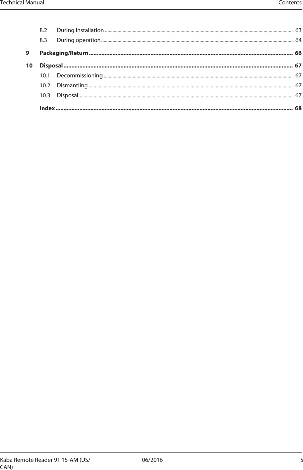
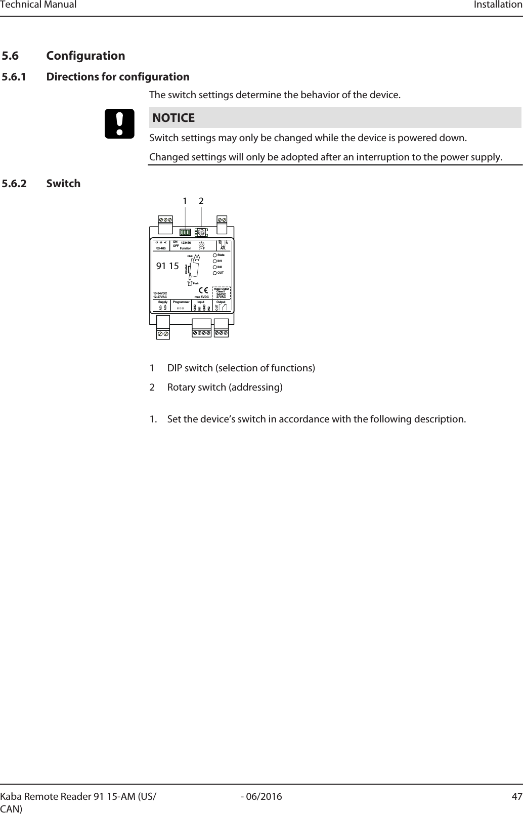
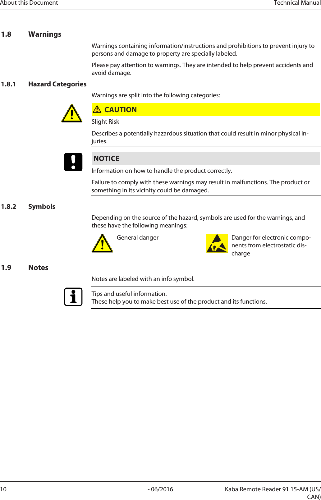
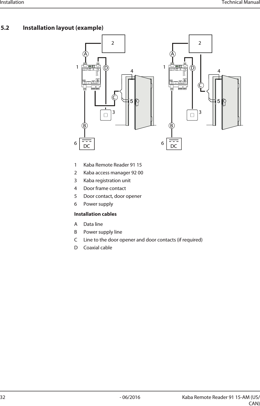
![Technical Manual About this Document9- 06/2016Kaba Remote Reader 91 15-AM (US/CAN)1.5 Change LogThe most important changes to the last issue of this manual are listed below:Version number Edition Brief descriptionTM_RemoteReader9115-AM-US-CAN_201606_en06/2016 • First edition1.6 Orientation in the documentThis document contains the following orientation aids to facilitate finding of specifictopics:• The table of contents at the beginning of the manual gives an overview of alltopics.• The header always contains the respective main chapter.• Cross references always indicate the number of the chapter in which the supple-mentary information can be found. Example [ 5.7].• An index in the alphabetical order is given at the end of the manual.1.7 Abbreviations/Term DefinitionsAbbreviation/term DescriptionRemoteReader • Kaba Remote Reader 91 15Device • Kaba Compact Reader 91 10 AMRegistration unit • Kaba Registration Unit 90 00• Kaba Registration Unit 90 01• Kaba Registration Unit 90 02Host • Host systemControl unit • Kaba Access ManagerKCP Kaba Communication Protocol (RS-485)KMM Kaba Media ManagerAccess Manager • Kaba Access Manager 92 00 MRD• Kaba Access Manager 92 00 LEGIC• Kaba Access Manager 92 00 MIFAREProgrammer • Kaba Programmer 1460](https://usermanual.wiki/dormakaba-EAD/KRR9115-K5/User-Guide-3123497-Page-9.png)
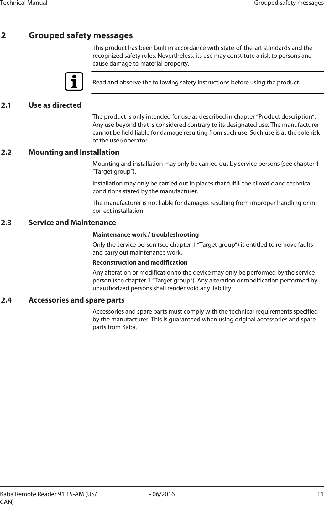
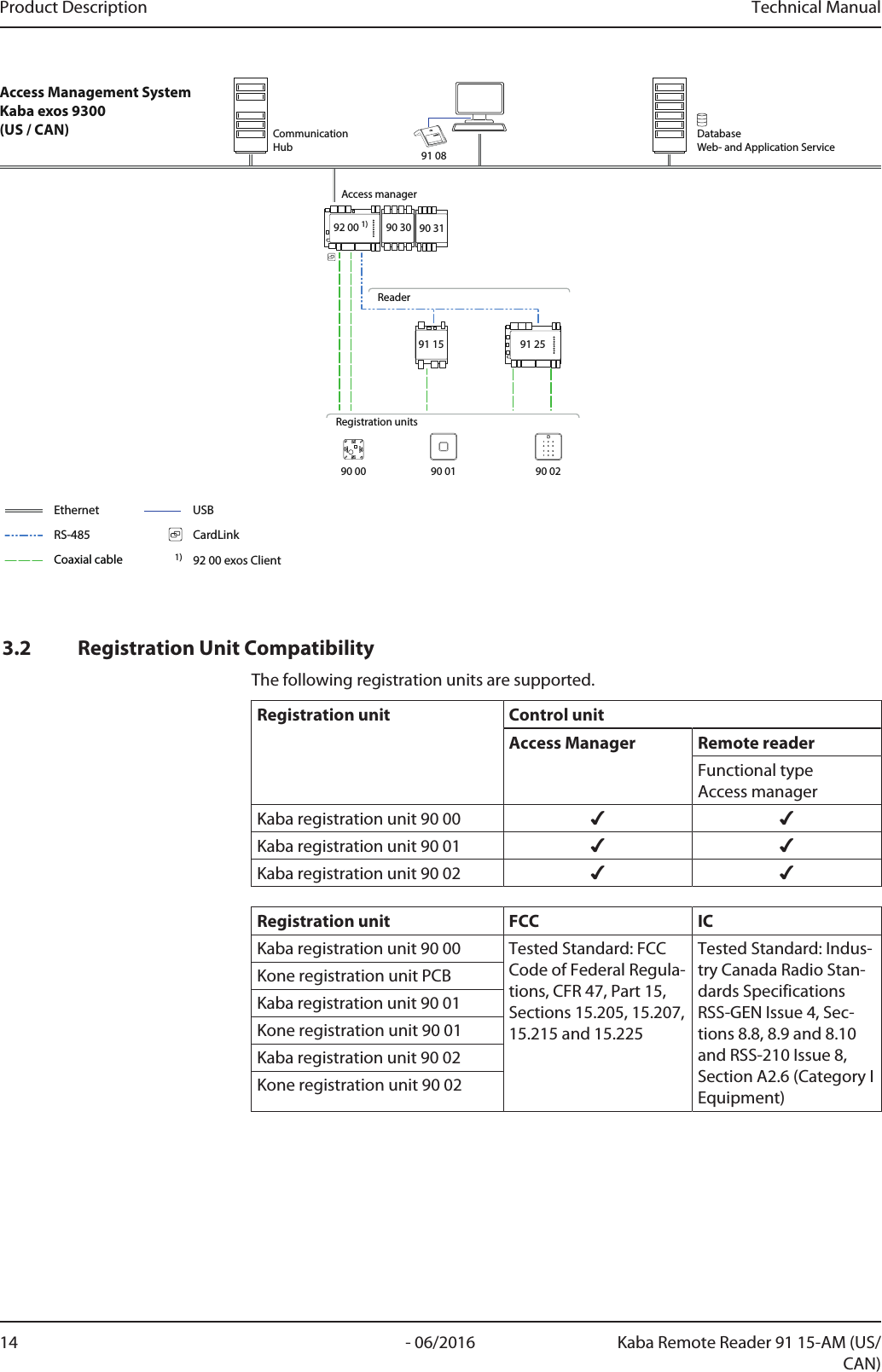
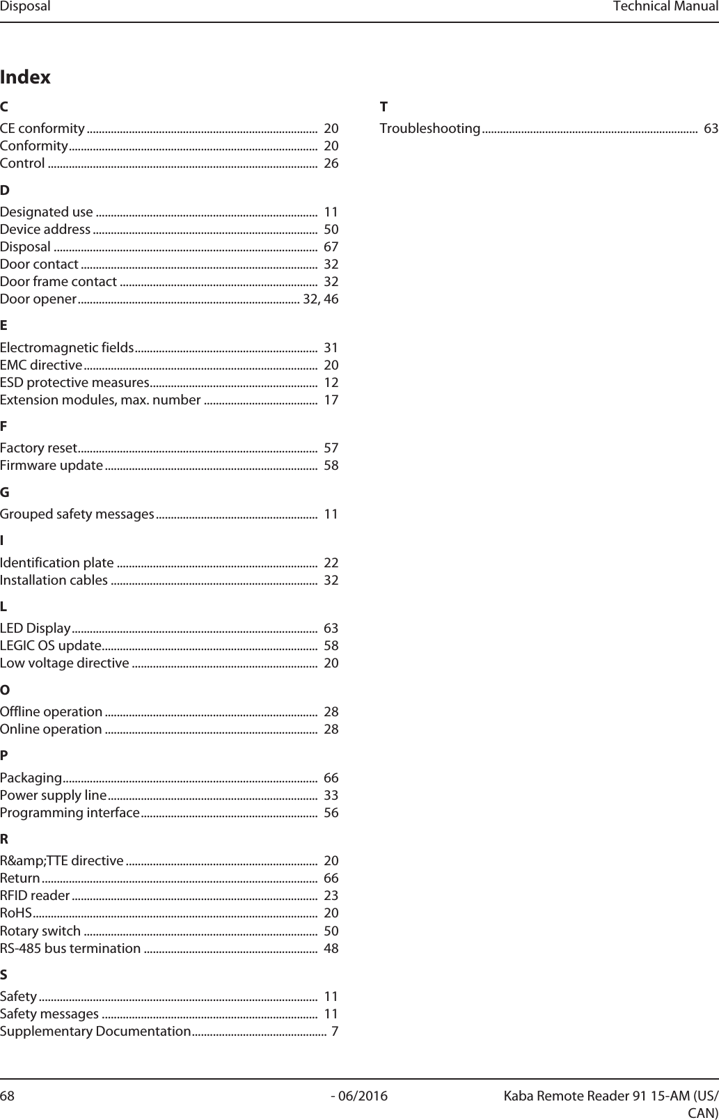
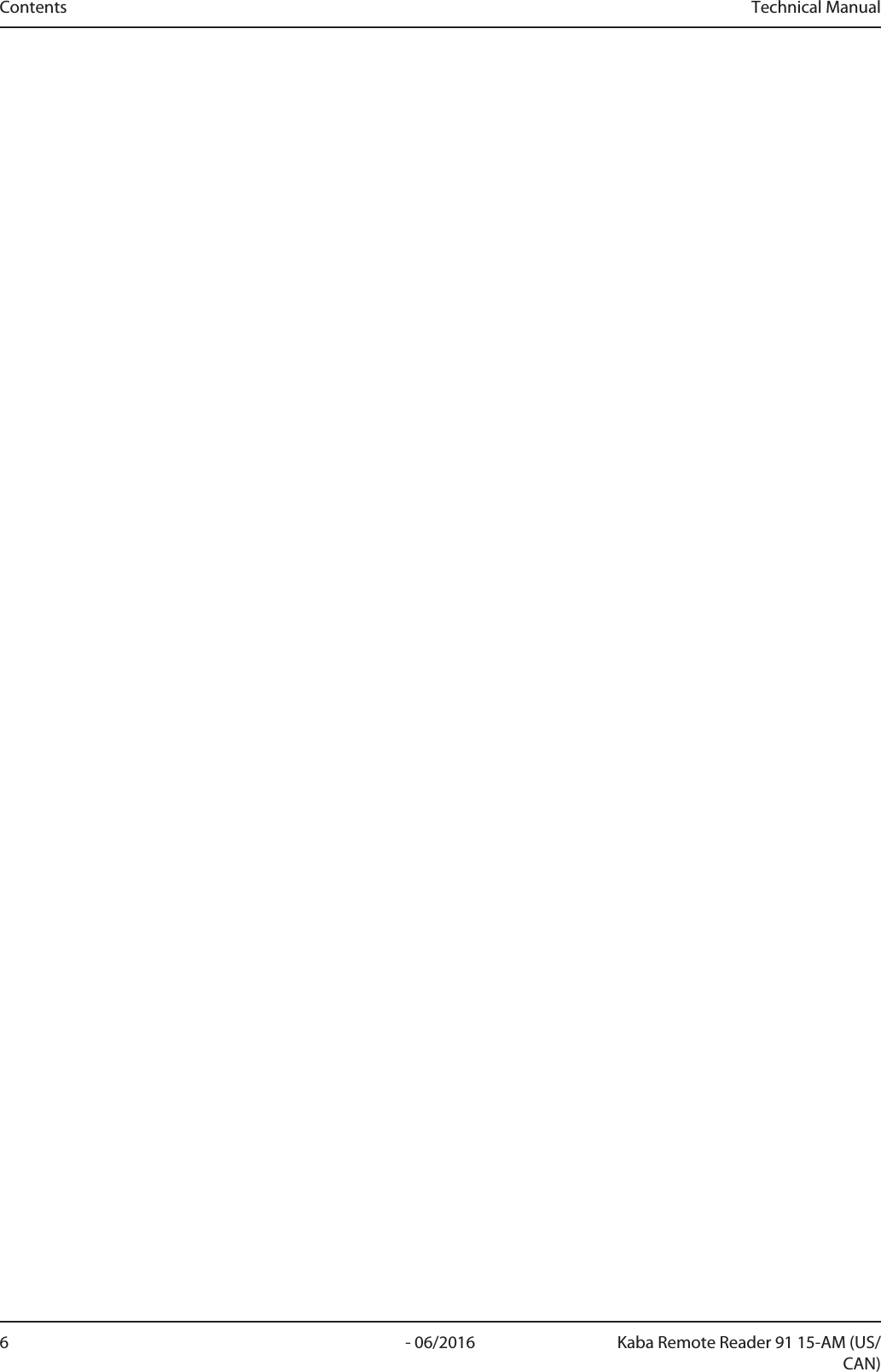
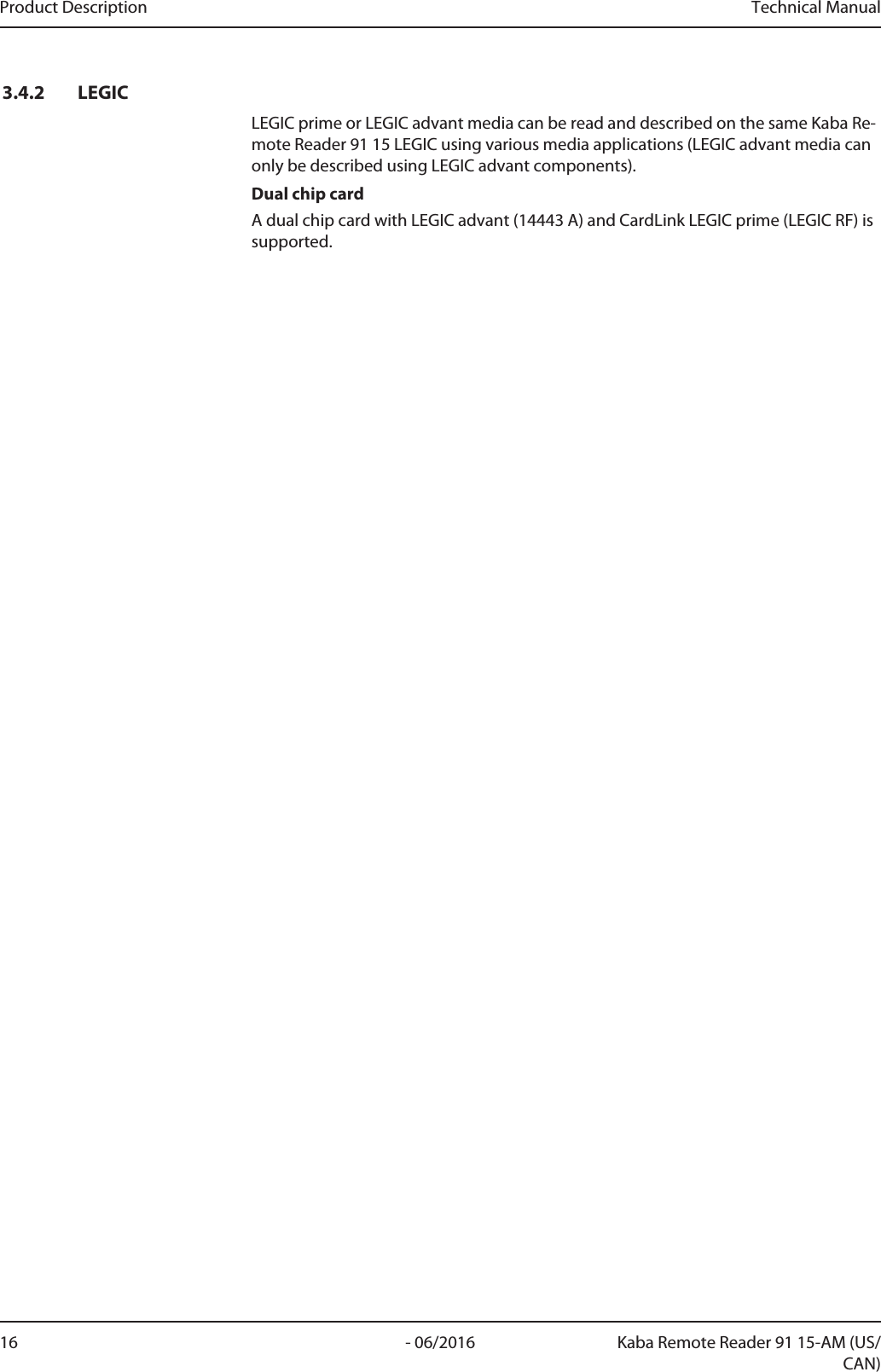
![Technical Manual Product Description15- 06/2016Kaba Remote Reader 91 15-AM (US/CAN)3.3 Operating modesThe door configuration determines the operating mode of the device. A detailed de-scription of the door configurations and their operating modes can be found in thechapter 'Electric strike' operating mode [}4.9].3.4 Supported RFID Standards with Possible Media DefinitionsThe following table shows the RFID standards and media definitions supported bythe device.The Kaba Remote Reader 91 15 recognizes up to eight different media definitions atthe same time.Media definitions Supported RFID technologiesMIFAREDESFireMI-FAREClas-sicLEGICadvant LEGICprimeISO14443AISO14443AISO14443AISO15693LEGICRFUnique number (UID)*1✔✔✔✔ -Safe UID - - - - ✔Card ID ✔✔✔✔ -Kaba group header - - ✔✔✔Kaba advant ID - - ✔ ✔ -LEGIC access™ (advant)- - ✔ ✔ -LEGIC access™ pool(prime)----✔CardLink1.1Data ✔✔✔✔ -Actuatorstatus✔✔✔✔ -Mediatraceback*2✔-✔- -CardLink1.0Data incl.actuatorstatus----✔Additional medianumbers✔✔✔✔✔*1 The LEGIC chip set does not use the safe UID command setso that UID from other media, such as MIFARE, can also beread.*2 Media traceback information can only be read out directlyon the access manager and no media traceback informa-tion is written.3.4.1 MIFAREThe system can evaluate everything that can be defined in Kaba media manager. MI-FARE DESFire or MIFARE Classic media can be read and described on the same KabaRemote Reader 91 15 MIFARE using various media applications.](https://usermanual.wiki/dormakaba-EAD/KRR9115-K5/User-Guide-3123497-Page-15.png)
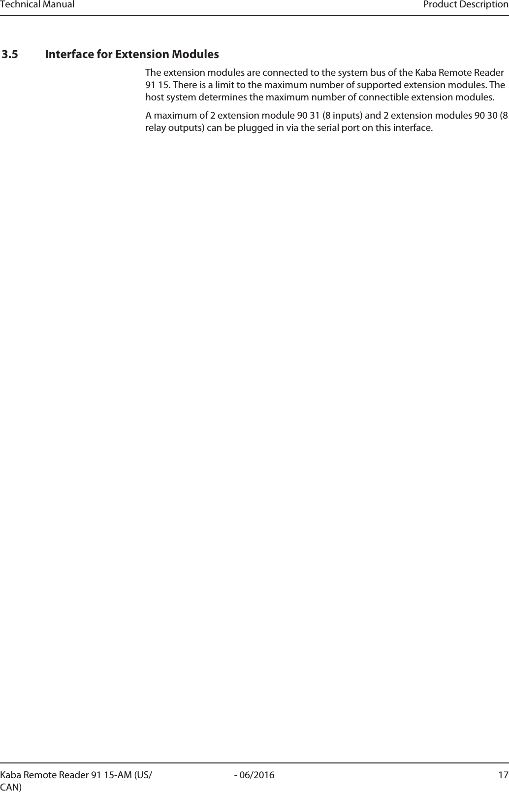
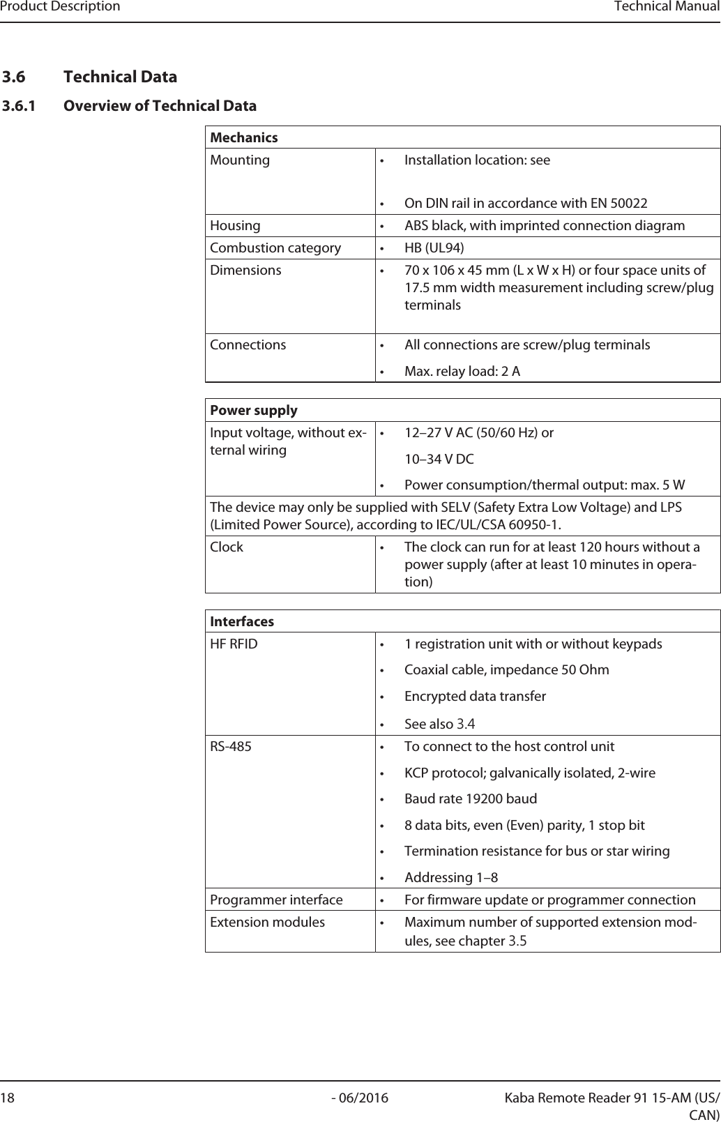
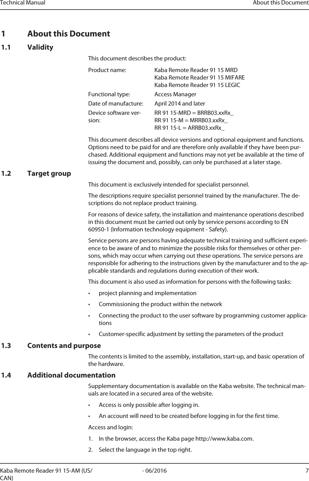
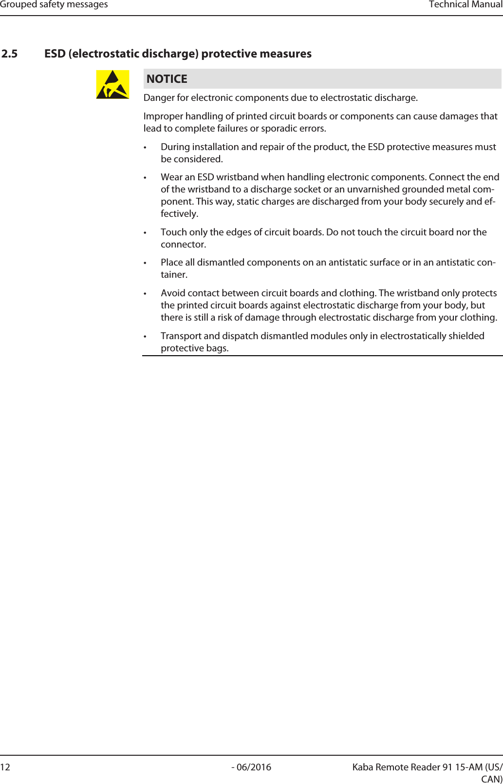
![Technical Manual Product Description19- 06/2016Kaba Remote Reader 91 15-AM (US/CAN)Inputs and outputs2 binary inputs• With internal power supply and common ground,for connection of insulated switches• Maximum 5VDC• Line monitoring (can be disabled)• LED status indicator1 relay output • Switch contact: max. 30VDC/AC max. power 2A• Switching cycles at 30V DC/1Atypical 500,000 (VdS 2358 requirement is 200,000)• Switching cycles at 30V DC/2Atypical 100,000• LED status indicatorAmbient conditionsAmbient conditions • Operating temperature: -25°C to +70°C• Storage temperature: -40°C to +85°C• Relative humidity: 0% to 95%, non-condensing• Protection class as per IEC 60529: IP20Also see about this23.4Supported RFID Standards with Possible Media Definitions [}15]25.1.2Installation site [}31]](https://usermanual.wiki/dormakaba-EAD/KRR9115-K5/User-Guide-3123497-Page-19.png)
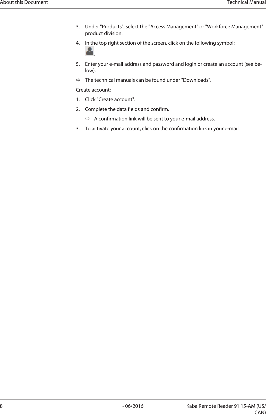
![Product Description Technical Manual20 - 06/2016 Kaba Remote Reader 91 15-AM (US/CAN)3.7 ConformityThis product conforms to the following standards:EN 60950-1:2006/A2:2013 UL 60950-1:2007/R:2014-10CAN/CSA-C22.2 No. 60950-1:2007/A2:2014-10EN 301 489-1 V1.8.1:2008EN 301 489-3 V1.4.1:2002EN 300 330-1 V1.7.1:2010EN 300 330-2 V1.5.1:2010in accordance with the provisions of the EC directives2006/95/EC Low voltage directive 1999/5/EC R&TTE directive2004/108/EC EMC directiveRoHS This device complies with the regulations of the Directive 2011/65/EU of the Euro-pean Parliament and of the Council of June 8, 2011, on the restriction of the use ofcertain hazardous substances in electrical and electronic equipment.The original Declaration of Conformity can be downloaded from www.kaba.com/conformity in PDF format.Tested Standard:FCC Code of Federal Regulations, CFR 47, Part 15, Sections 15.205, 15.207, 15.215 and15.225FCC ID NVI-KRR9115-K5FCC § 15.19This device complies with Part 15 of the FCC rules. Operation is subject to the follow-ing two conditions: (1) This device may not cause harmful interference, and (2) thisdevice must accept any interference received, including interference that may causeundesired operation.FCC § 15.21 (Warning Statement)[Any] changes or modifications not expressly approved by the party responsible forcompliance could void the user’s authority to operate the equipment.FCC § 15.105Note: This equipment has been tested and found to comply with the limits for a ClassA digital device, pursuant to part 15 of the FCC Rules. These limits are designed toprovide reasonable protection against harmful interference when the equipment isoperated in a commercial environment. This equipment generates, uses, and can ra-diate radio frequency energy and, if not installed and used in accordance with the in-struction manual, may cause harmful interference to radio communications. Opera-tion of this equipment in a residential area is likely to cause harmful interference inwhich case the user will be required to correct the interference at his own expense.Tested Standard:Industry Canada Radio Standards Specifications RSS-GEN Issue 4, Sections 8.8, 8.9and 8.10 and RSS-210 Issue 8, Section A2.6 (Category I Equipment)](https://usermanual.wiki/dormakaba-EAD/KRR9115-K5/User-Guide-3123497-Page-20.png)
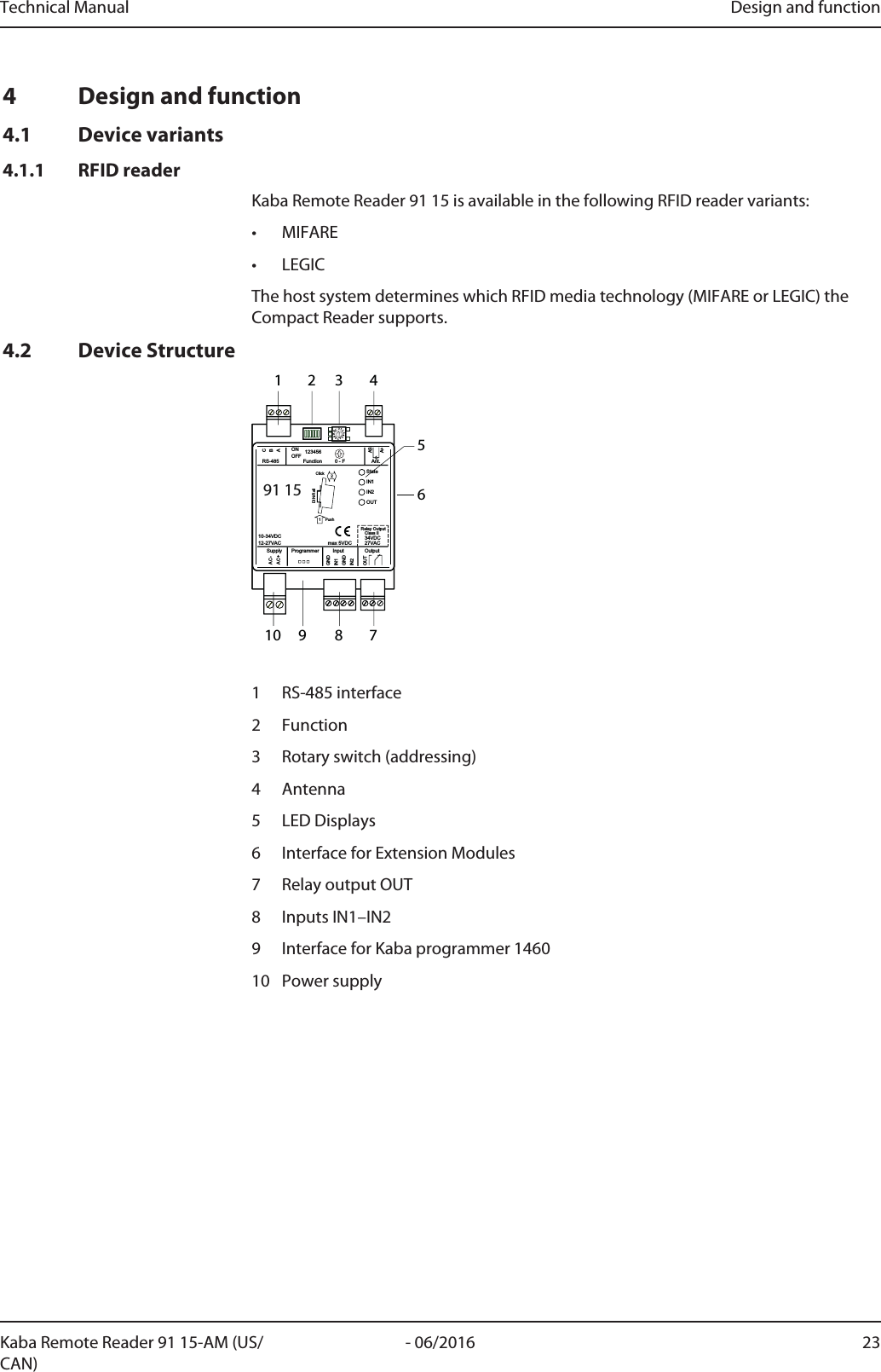
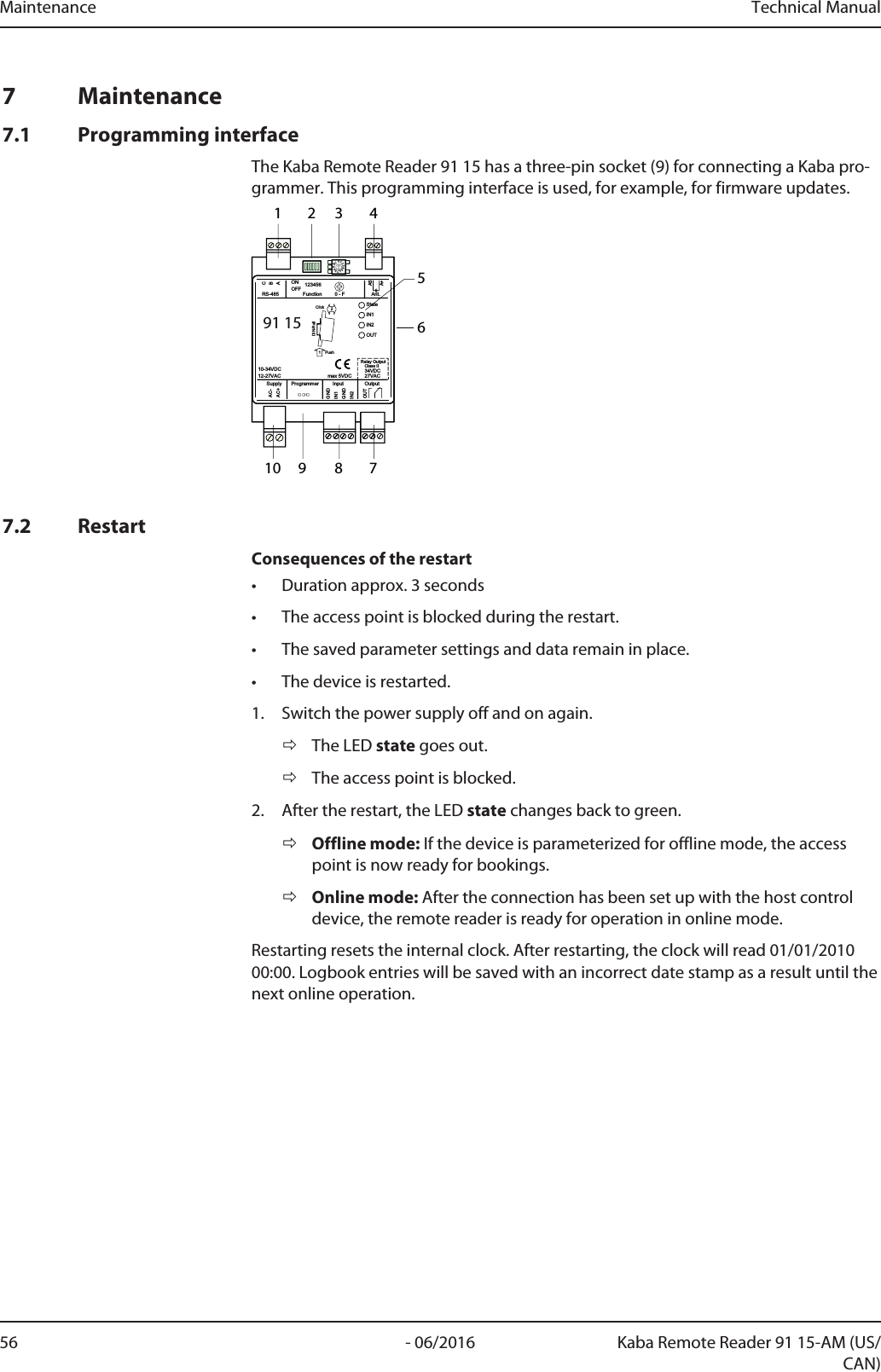
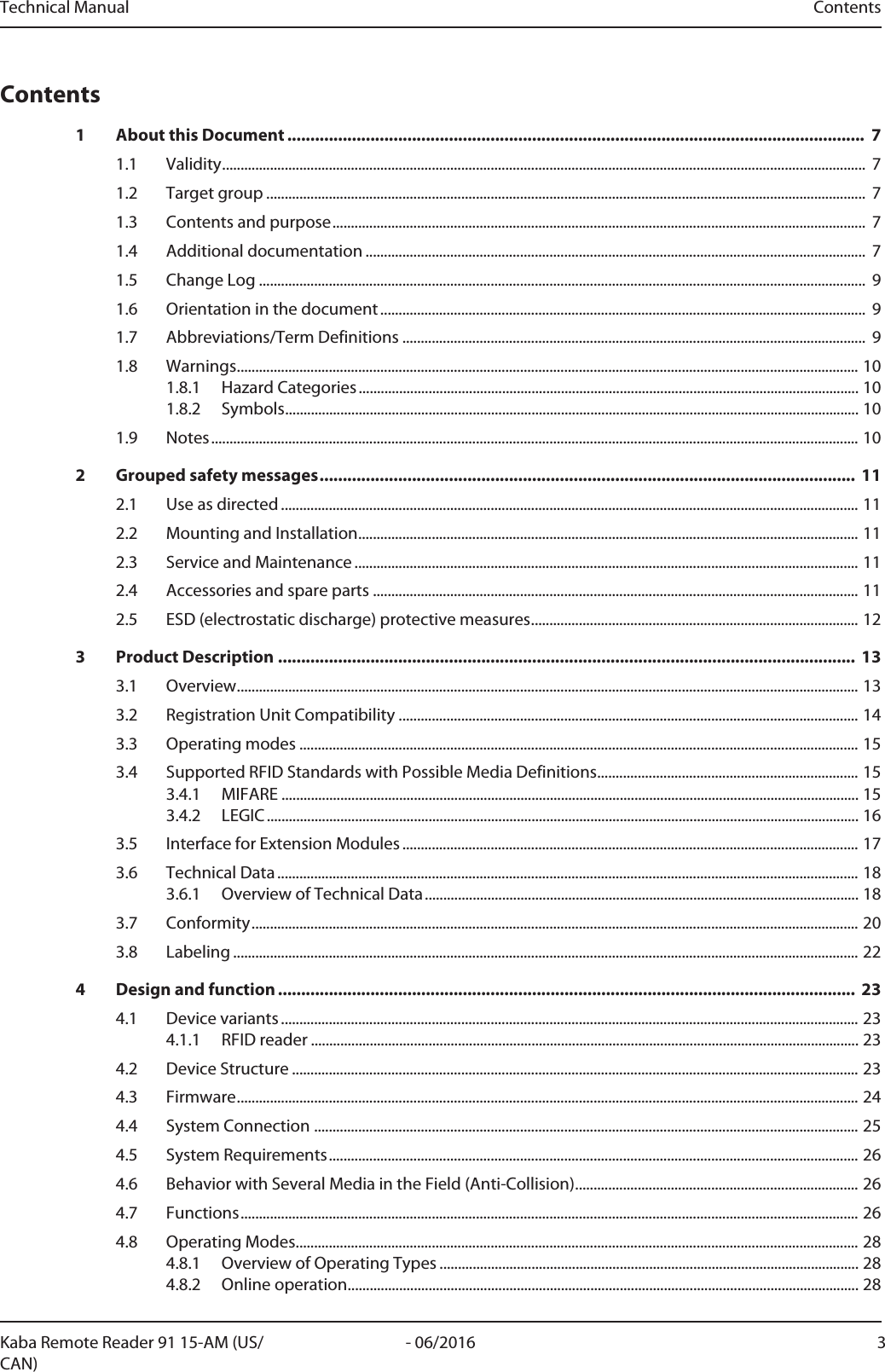
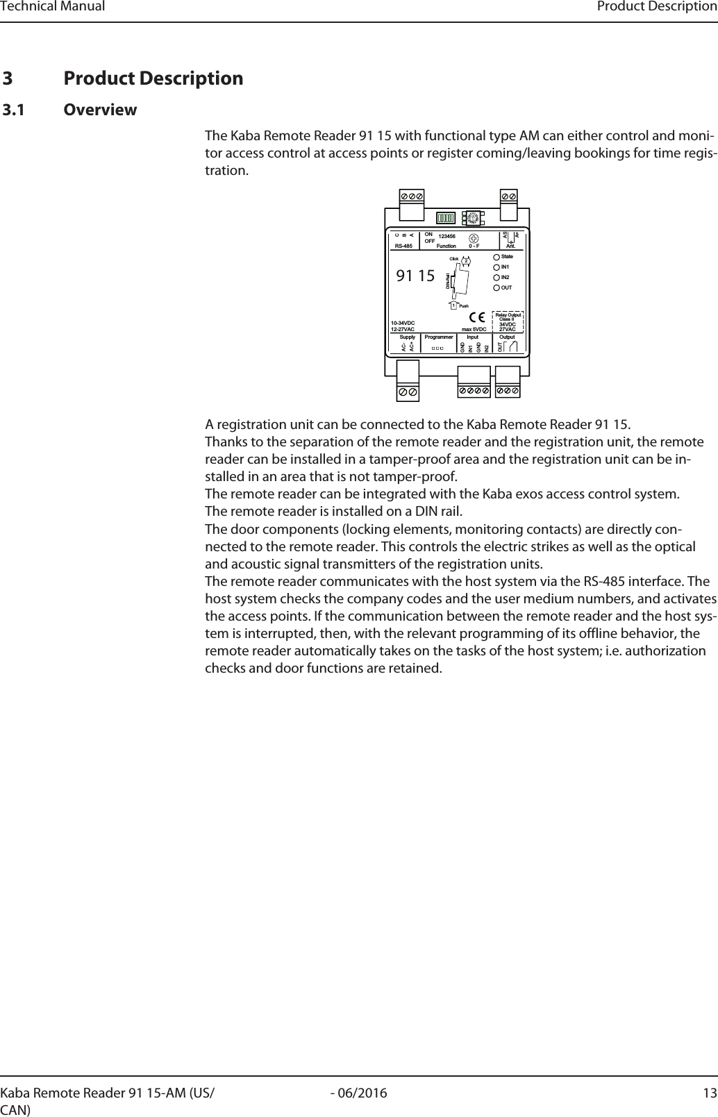
![Technical Manual Design and function25- 06/2016Kaba Remote Reader 91 15-AM (US/CAN)4.4 System Connection91 15StateIN1IN2OUTGNDAC-AC+BACGNDIN1IN221PushClickDIN-RailASA+OUTOutputAnt.Function 0 - F123456ONOFFRS-485InputProgrammerSupply10-34VDC12-27VAC 34VDCClass IIRelay Output27VACmax 5VDC1 2 34 5 67 8 91 0 EGNDGNDGNDGNDGNDStateIN1IN2IN3IN4OUT1OUT2OUT35VRxTx0VTamperIN1IN2IN3IN4Vs-Vs-Vs+Vs+3s Restart10s upon power-on Factory/IP Reset100MBitLink/ActOUT1OUT2OUT3Supply 10-34VDCOutput max. 34VDC/27VACInput max. 5VDCEthernet5VRxTx0VRS-232 B RS-232 A Ant. B Ant. AASA+21PushClickDIN-RailASA+CBARS-485open1204k7Access Manager123The Remotereader communicates with the host control unit via the RS-485 interface.Functions of the host control unit (1)• Checking access data received by the Remotereader• Authorization check• Sending commands for optical and acoustic user guidance to the Remotereader• Sending commands for relay control to the RemotereaderFunctions of the remote reader (2)See Overview [}3.1]Functions of the registration unit (3)• Reading the media held up (RFID)• Optical and acoustic user guidance• Keypad for PIN entry and additional functions with numeric codesBehavior in the event of an interruption in communicationIn the event of an interruption in communication, the Remotereader automaticallytakes over some of the tasks of the host control unit. A simplified authorization checkand simplified door functions remain available. The parameterization determines off-line behavior.](https://usermanual.wiki/dormakaba-EAD/KRR9115-K5/User-Guide-3123497-Page-25.png)
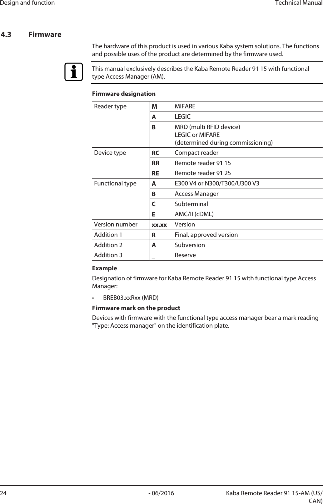
![Design and function Technical Manual26 - 06/2016 Kaba Remote Reader 91 15-AM (US/CAN)4.5 System RequirementsHost control unit• Kaba access manager 92 00 MRD• Kaba access manager 92 00 LEGIC (for RemotereaderLEGIC)• Kaba access manager 92 00 MIFARE (for Remotereader MIFARE)System software• Kabaexos93004.6 Behavior with Several Media in the Field (Anti-Collision)The device (Kaba Remote Reader 91 15) can recognize several LEGIC advant user me-dia (ISO 14443 A) in the field simultaneously. Only the first user medium that corre-sponds to the search criteria defined in the system is considered. The remaining usermedia are ignored.4.7 FunctionsAll data for access decisions are saved in the host control device. The authorizationcheck of a badge and access control are undertaken by the control device.Functions available before connection to the host systemStandalone access control (without host system); see chapter "Standalone AccessControl without Host System" CommissioningAccess control functions• Authorization check using badges and temporal authorization including verifica-tion• Connection of a remote registration unit• Control of optical and acoustic signal transmitters of the registration unit• Control of electric strikes (doors with electrical blocking elements)• Support for a connected door release button or door handle contact• Monitoring of the door status with frame contact, bolt monitoring and door han-dle contact• CardLink support: Validating and Invalidating• CardLink support: Validation and UID additional recording (LEGIC only)• Hold-open mode, so that, when access is authorized, the door remains open foras long as the badge remains within range of the antenna (field)Restrictions with interrupted connection (offline)MIFAREReduced authorization check using site keys. Door function is retained depending on the offline parameter setting, see Switch[}5.6.2].• Authorization check using site keys. A maximum of eight site keys can be saved.• Not taken into consideration: Time Zones• Logbook for 2000 events• No room monitoring/balancing and no CardLink functionality• No change in fabrication keyLEGIC](https://usermanual.wiki/dormakaba-EAD/KRR9115-K5/User-Guide-3123497-Page-26.png)
![Technical Manual Design and function27- 06/2016Kaba Remote Reader 91 15-AM (US/CAN)Reduced authorization check using segment search keys. Door function is retaineddepending on the offline parameter setting, see Switch [}5.6.2].• Authorization check using segment search keys. A maximum of eight segmentsearch keys can be saved.• Not taken into consideration: Time Zones• Logbook for 2000 events• No room monitoring/balancing and no CardLink functionalityRestored connectionAutomatic forwarding of saved bookings as well as status and alarm messages whenconnection is restored.](https://usermanual.wiki/dormakaba-EAD/KRR9115-K5/User-Guide-3123497-Page-27.png)
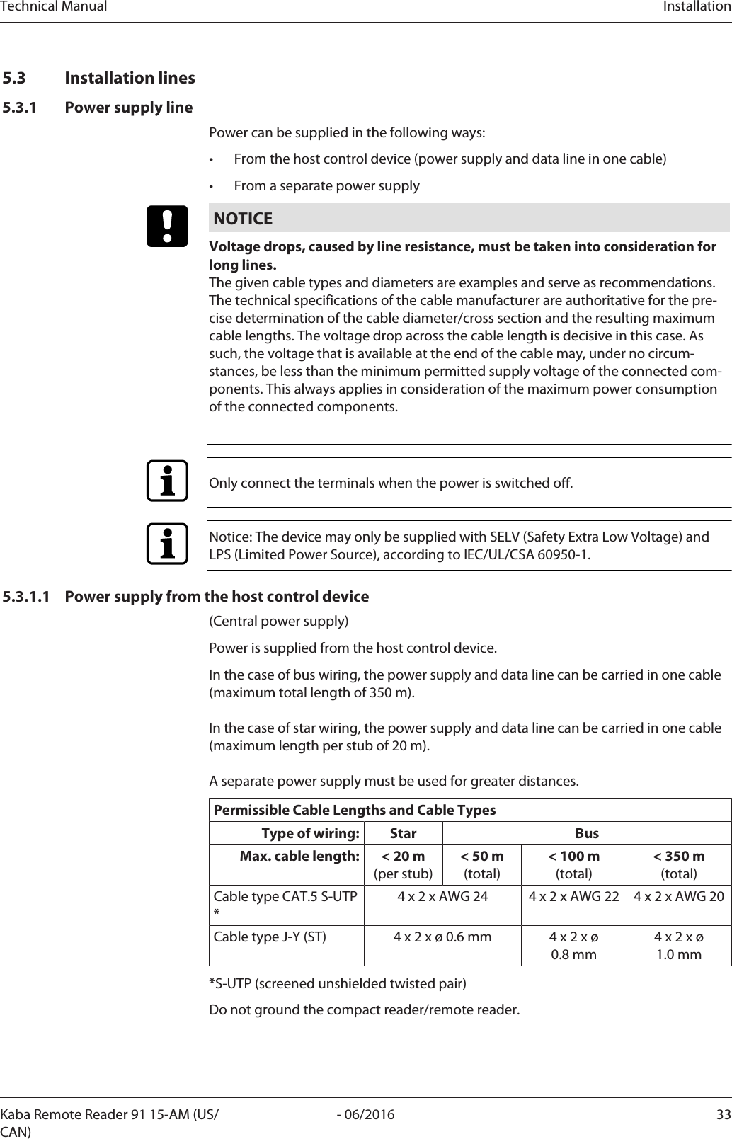
![Installation Technical Manual34 - 06/2016 Kaba Remote Reader 91 15-AM (US/CAN)5.3.1.2 Power supply and data transfer in separate cables(Local power supply)Data lines and power supply lines are carried with one of each in a cable.Power is supplied locally, e.g. from a power supply unit.A local power supply can be used in the following cases:• in long data lines• if there are increased requirements regarding the operational safety of the de-vice (offline capability).Permissible Cable Lengths and Cable TypesData line RS-485 Power supplyType of wiring: Star BusMax. cable length: < 100m (per stub)< 1200m(total)< 10mCable type CAT.5 S-UTP * 2 x 2 x AWG 24 1 x 2 x AWG 24Cable type J-Y (ST) 2 x 2 x ø 0.6mm 1 x 2 x ø 0.6mm*S-UTP (screened unshielded twisted pair)Notice: The device may only be supplied with SELV (Safety Extra Low Voltage) andLPS (Limited Power Source), according to IEC/UL/CSA 60950-1.5.3.2 Data line RS-485Only connect the terminals when the power is switched off.The device is connected to the host control device via a two-wire party line connec-tion (RS-485).For information on permissible cable lengths and cable types, please see:•Power supply from the host control device [}5.3.1.1]•Power supply and data transfer in separate cables [}5.3.1.2]5.3.2.1 CableNOTICELocal legal provisions (e.g., VDE) must be observed during installation of compo-nents. For notes on structured cabling, see the standard EN 50173.The cables recommended in the chapter Power supply line [}5.3.1] have a foilscreen and are designed based on S-UTP (screened unshielded twisted pair). The wirepairs are not individually shielded against each other (unshielded). Each pair com-prises two color-coded wires that are twisted together (twisted pair).NOTICEIt must be ensured that the screen is applied with the aid of the drain wire. The drainwire must be insulated to avoid short circuits on the circuit boards of the connecteddevices using a shrink-on tube or similar.](https://usermanual.wiki/dormakaba-EAD/KRR9115-K5/User-Guide-3123497-Page-34.png)
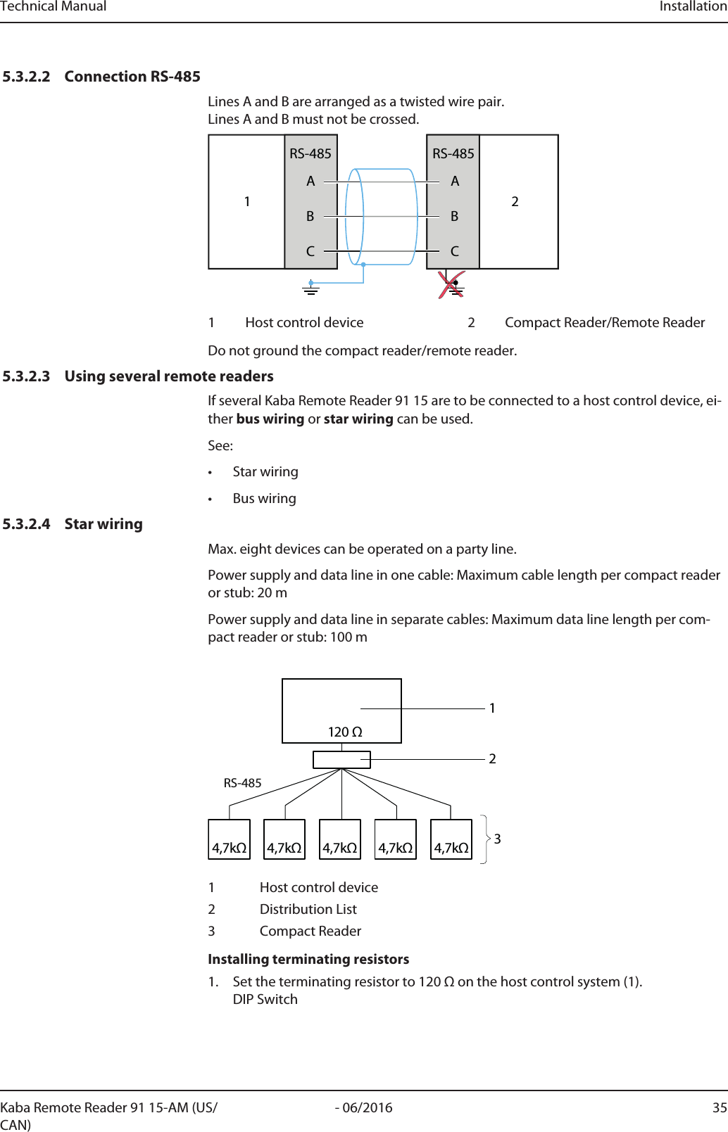
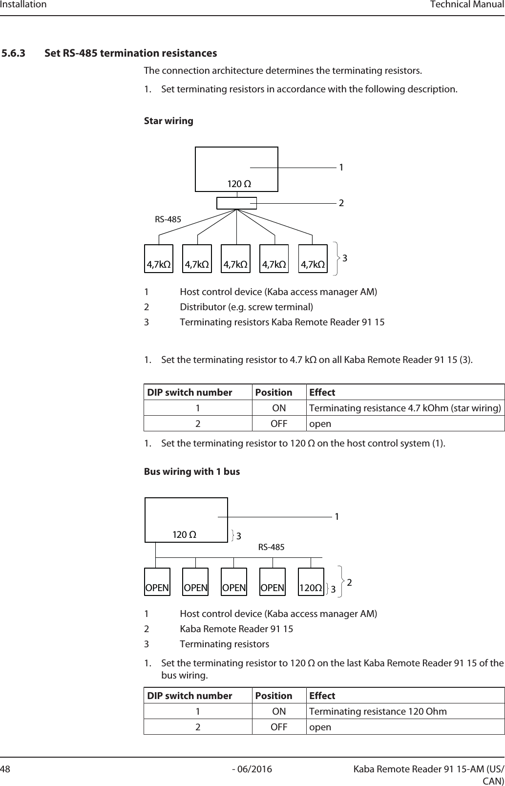
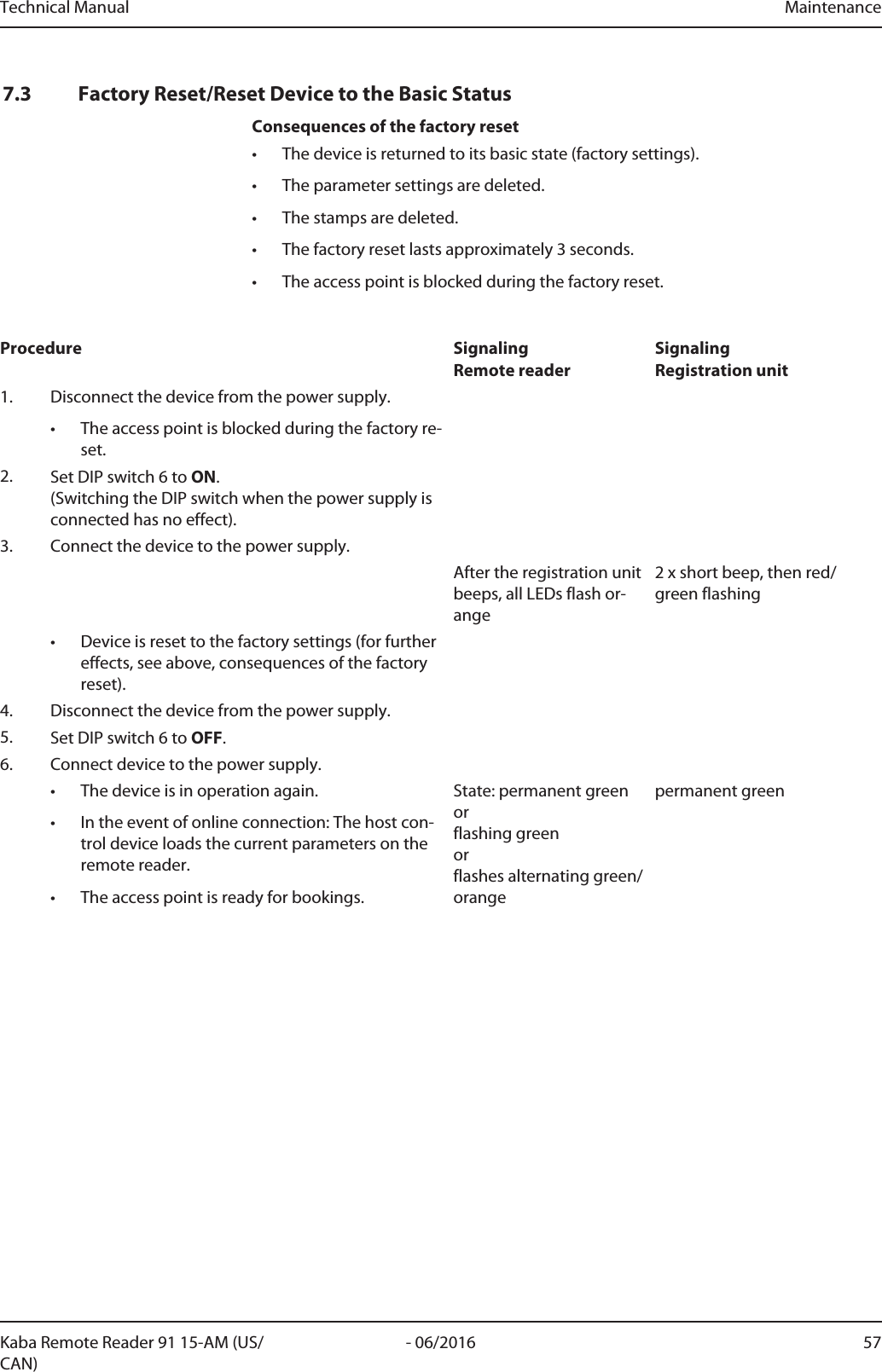
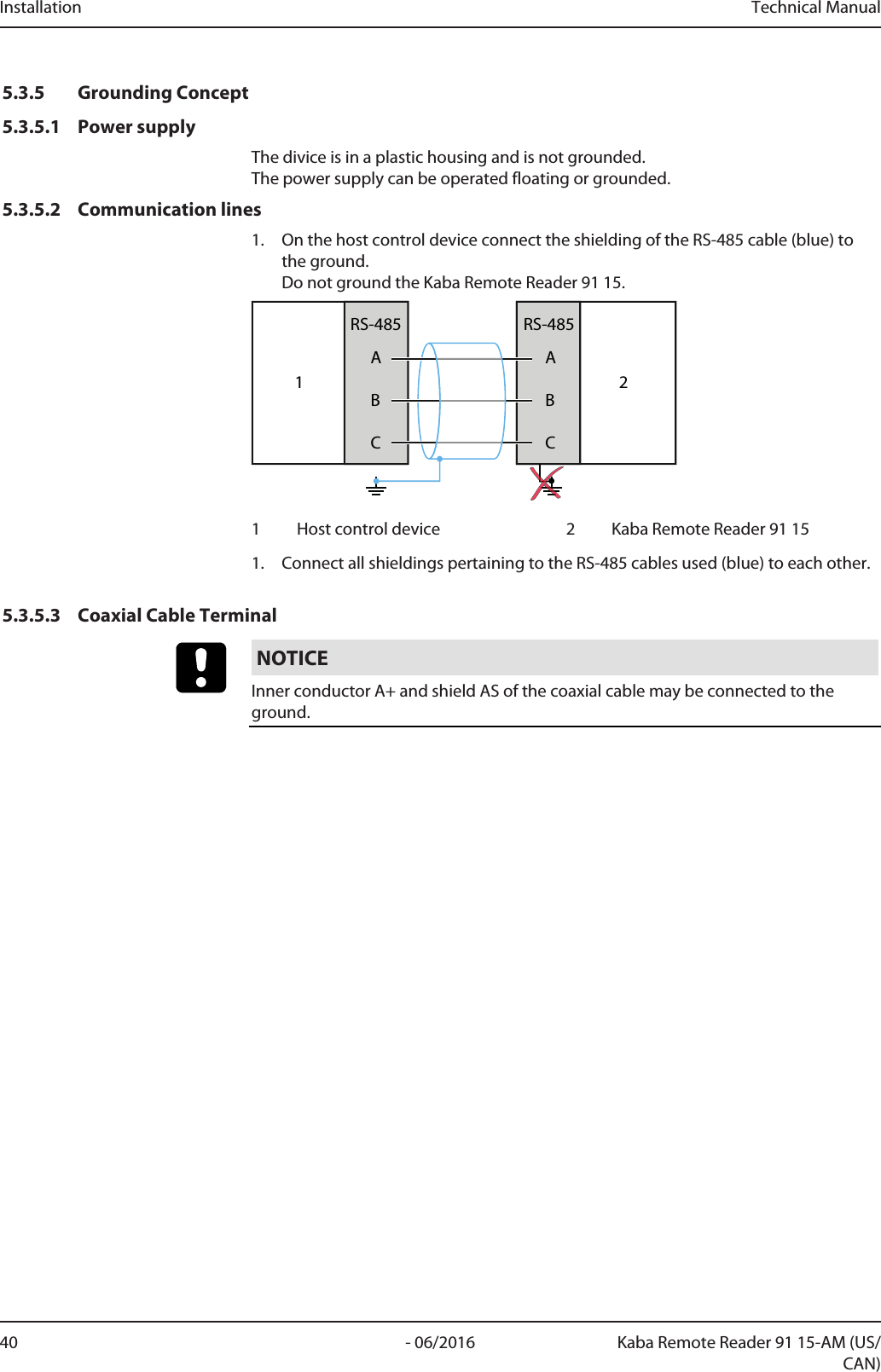
![Technical Manual Installation37- 06/2016Kaba Remote Reader 91 15-AM (US/CAN)5.3.2.5 Bus wiringA maximum of eight devices can be operated on a party line.Maximum total length of data lines (incl. stubs): 1200m A stub itself may be a maximum of 100m in length. The length of the party line can be increased using a repeater.5.3.2.5.1 Bus wiring with 1 bus120ΩOPENOPENOPENOPENRS-485120 Ω12331 Host control device2 Compact Reader or Remote Reader3 Terminating resistorsInstalling terminating resistors1. Set the terminating resistor to 120Ω on the host control system (1).2. On the last device in the bus wiring, set DIP switch 1 to ON (120Ω), and DIP switch 2 to OFF (open).3. On all other devices in the bus wiring, set DIP switch 1 and 2 to OFF (open).Set peripheral address1. Assign unique addresses to the devices connected to the bus.Set peripheral address [}5.6.4]Connecting shielding1. On the host control device connect the shielding of the RS-485 cable (blue) tothe ground.Do not ground the compact reader/remote reader.1ABCRS-485ABCRS-48521 Host control device 2 Compact Reader, Remote Reader2. Connect all shieldings of RS-485 cables (blue) used in the bus to each other.](https://usermanual.wiki/dormakaba-EAD/KRR9115-K5/User-Guide-3123497-Page-37.png)
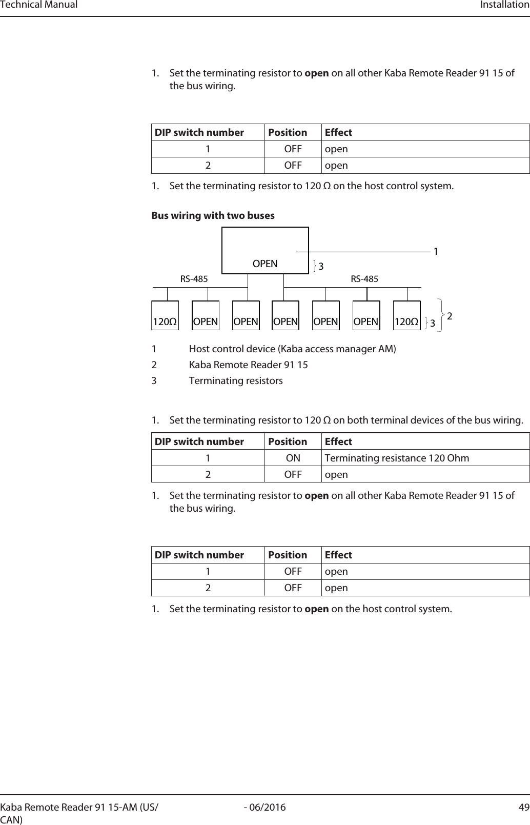
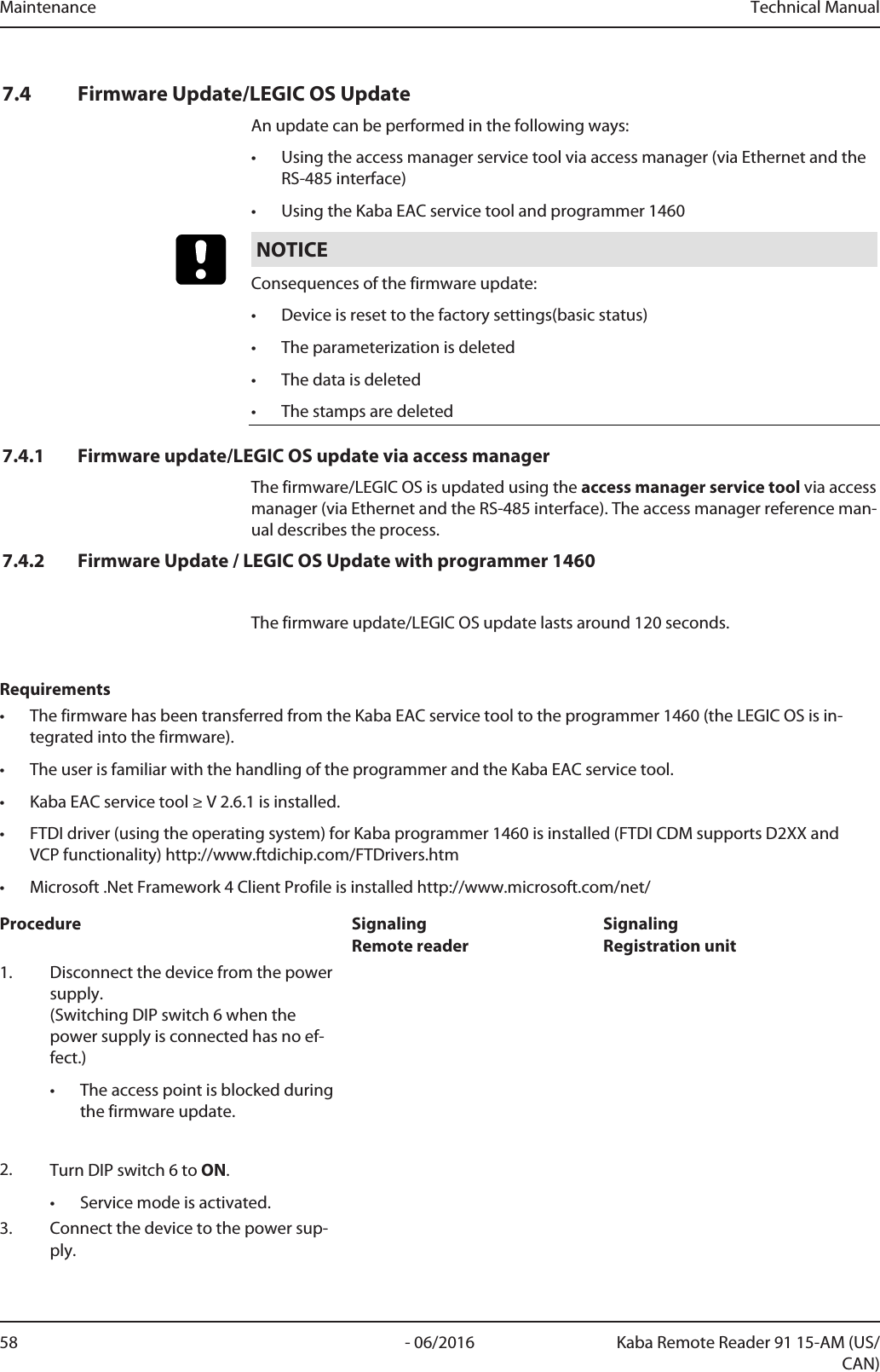
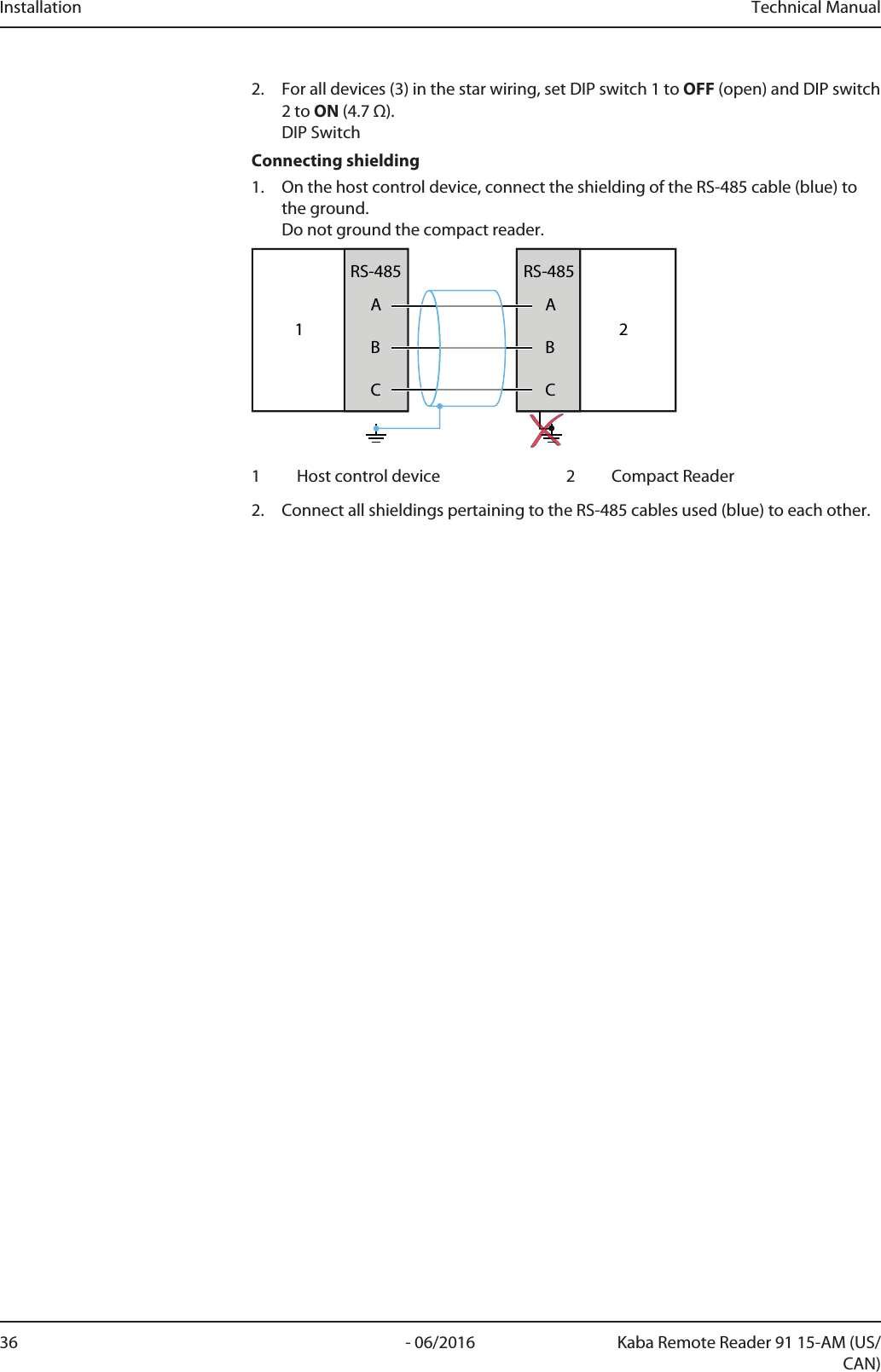
![Installation Technical Manual38 - 06/2016 Kaba Remote Reader 91 15-AM (US/CAN)5.3.2.5.2 Bus wiring with two buses120Ω120ΩRS-485RS-485OPEN233OPEN OPENOPENOPENOPEN11 Host control device2 Compact Reader or Remote Reader3 Terminating resistorsInstalling terminating resistors1. Set the terminating resistor to OFF (open) on the host control system.2. On both terminal devices in the bus wiring, set DIP switch 1 to ON (120 Ω), andDIP switch 2 to OFF (open).3. On all other devices in the bus wiring, set DIP switch 1 and 2 to OFF (open).Set peripheral address1. Assign unique addresses to the devices connected to the bus.Set peripheral address [}5.6.4]Connecting shielding1. On the host control device connect the shielding of the RS-485 cable (blue) tothe ground.Do not ground the compact reader/remote reader.1ABCRS-485ABCRS-48521 Host control device 2 Compact Reader, Remote Reader2. Connect all shieldings of RS-485 cables (blue) used in the bus to each other.](https://usermanual.wiki/dormakaba-EAD/KRR9115-K5/User-Guide-3123497-Page-38.png)

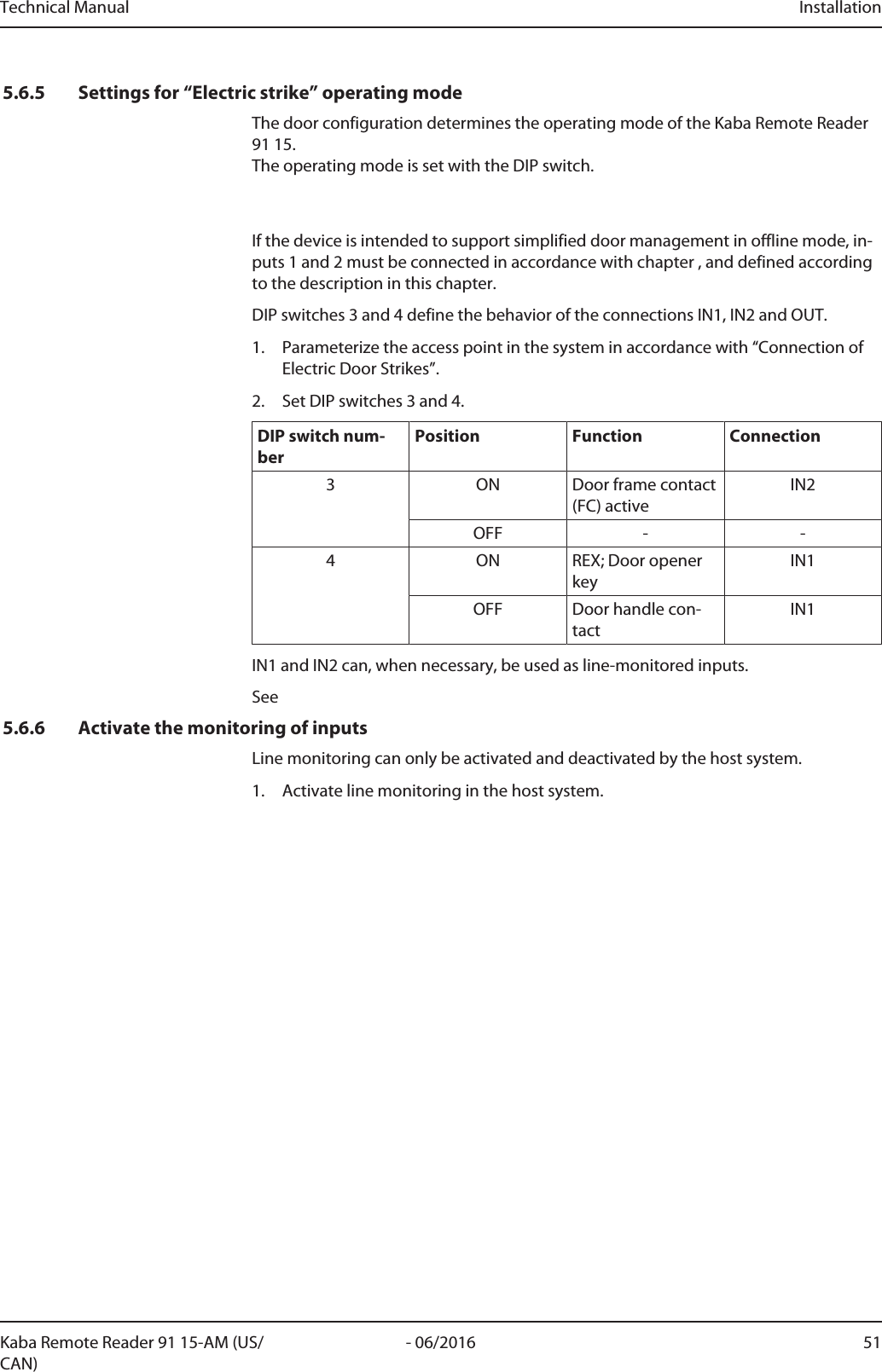
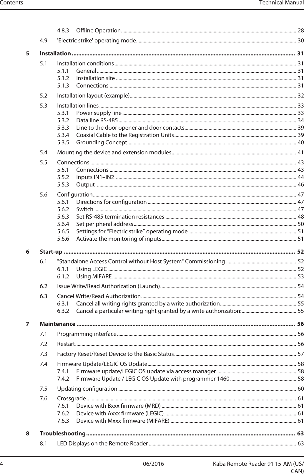
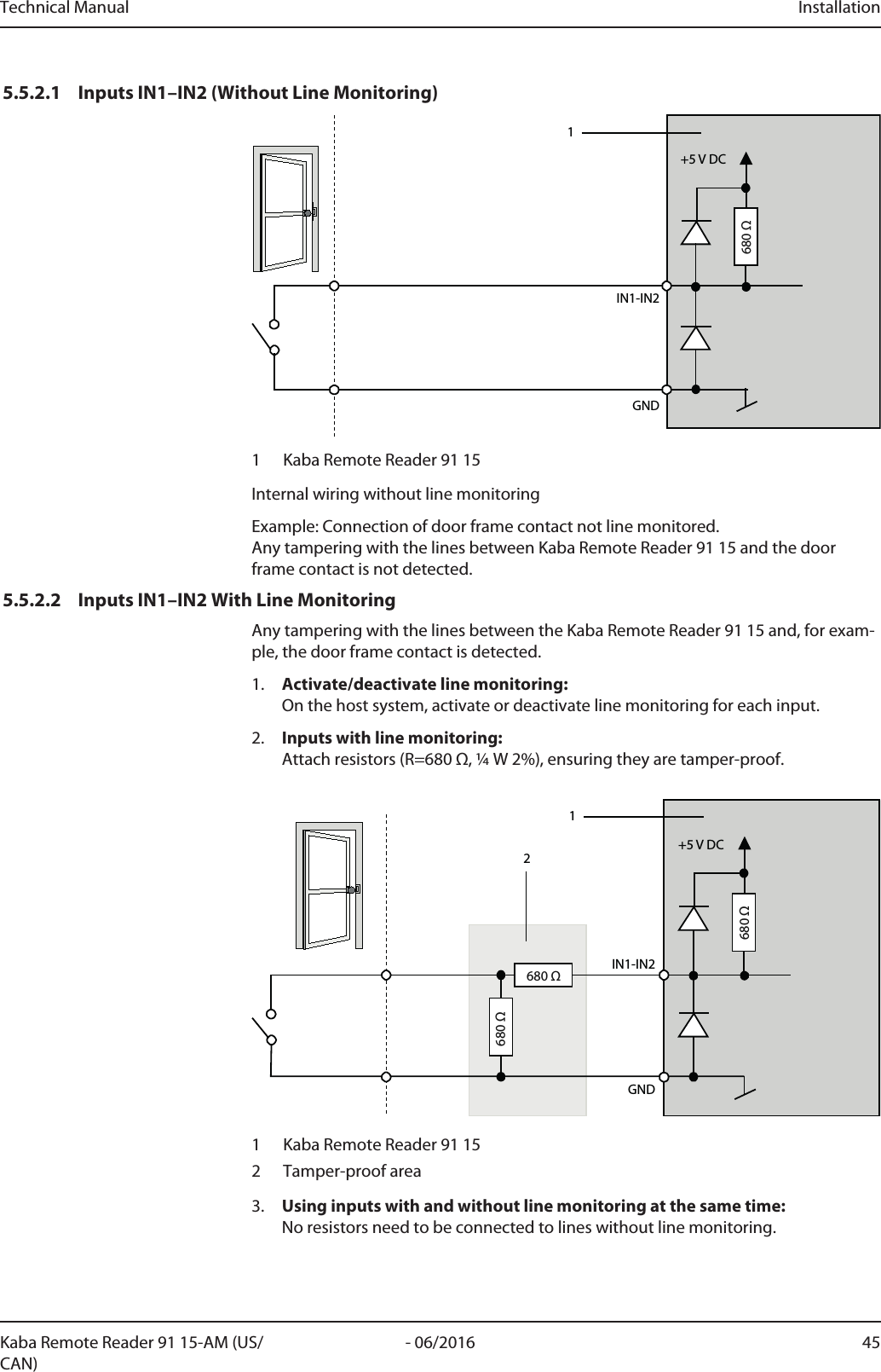
![Installation Technical Manual44 - 06/2016 Kaba Remote Reader 91 15-AM (US/CAN)Item Connection/switch Remark9 Power supply 12–27VAC (50/60Hz) or 10–34VDCNotice: The device may only be supplied with SELV (Safety Extra LowVoltage) and LPS (Limited Power Source), according to IEC/UL/CSA60950-1.See also: Using several remote readers [}5.3.2.3]Set RS-485 termination resistances [}5.6.3]5.5.2 Inputs IN1–IN2NOTICEConnecting Isolated Inputs.The function of the inputs and outputs depends on the control unit used and its pa-rameter settings.The logic (normally open [active low]/normally closed [active high]) of the inputs canbe changed by the host system.Allocation MeaningGND (common ground)IN1 (input 1)Door handle contact or door opener key REXIN2 (input 2)Frame contact (FC)If the Kaba Remote Reader 91 15 needs to behave in the same way in both online andoffline operation, the inputs and relay outputs must be connected according to theoperating mode and configured with the DIP switches.DIP switches 3 and 4 define the function of inputs IN1 and IN2.DIP SwitchIN1 and IN2 can, when necessary, be used as line-monitored inputs.Inputs IN1–IN2 With Line Monitoring [}5.5.2.2]](https://usermanual.wiki/dormakaba-EAD/KRR9115-K5/User-Guide-3123497-Page-44.png)
![Installation Technical Manual46 - 06/2016 Kaba Remote Reader 91 15-AM (US/CAN)5.5.3 OutputThe function of the inputs and outputs depends on the control unit used and its pa-rameter settings.Output (OUT), e.g. for an electric strike:COMNC1NO21 Kaba Remote Reader 91 152 Free-wheeling diode for door openers with DC voltageorvaristor for door openers with AC voltage.Item* Meaning6 NC (normally closed)6 COM6 NO (normally open)*SeeContact load capacity: See OutputsAlso see about this25.5.1Connections [}43]5.5.3.1 Note on the use of door openersThe relay can be used to activate the door opener. For door openers that are sup-plied with DC voltage, a "free-wheeling" diode must be parallel-connected (in the re-verse direction) to the door opener for noise attenuation. A varistor must be con-nected parallel to AC voltage door openers.](https://usermanual.wiki/dormakaba-EAD/KRR9115-K5/User-Guide-3123497-Page-46.png)