dormakaba EAD LEGMRD RFID Reader User Manual TM T9700V2 201707 en
Kaba GmbH RFID Reader TM T9700V2 201707 en
UserManual.wiki
>
dormakaba EAD
>
LEGMRD User Manual
Users Manual
Navigation menu
Upload a User Manual
Namespaces
Wiki Guide
HTML
PDF
Info
Views
User Manual
Discussion / Help
Navigation
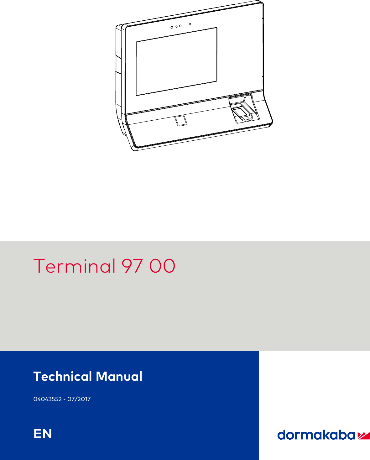
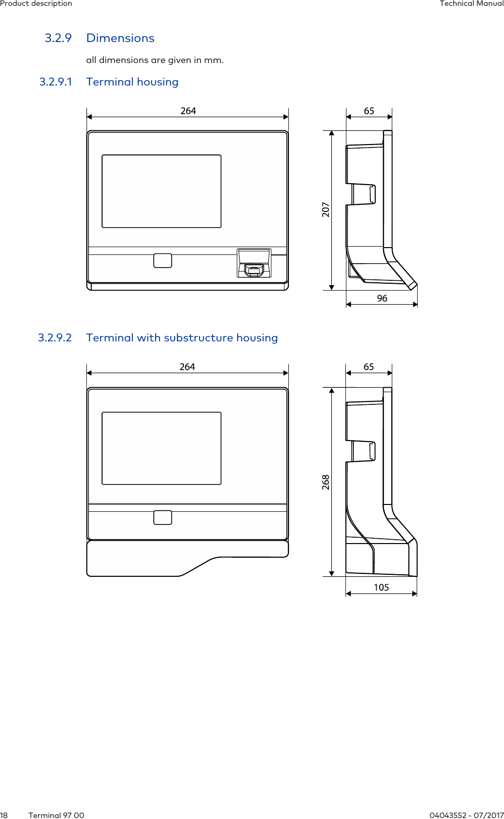
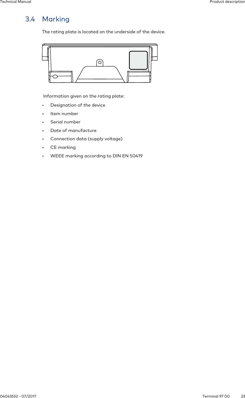
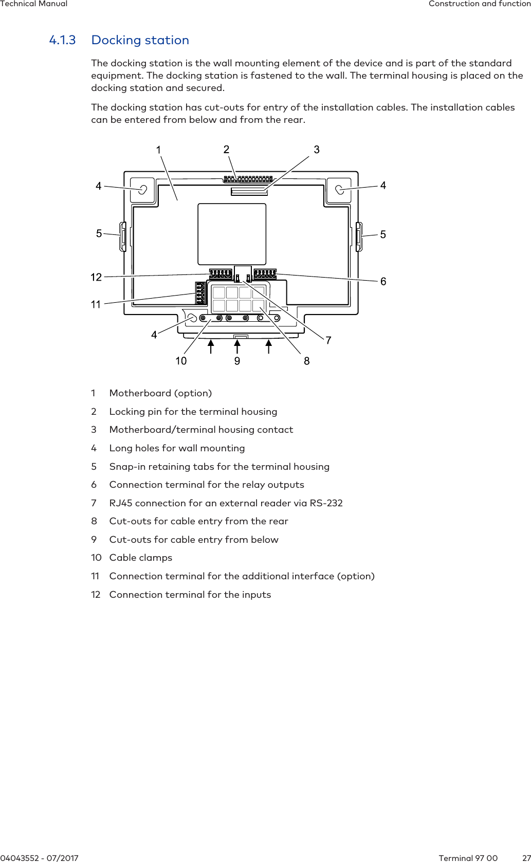
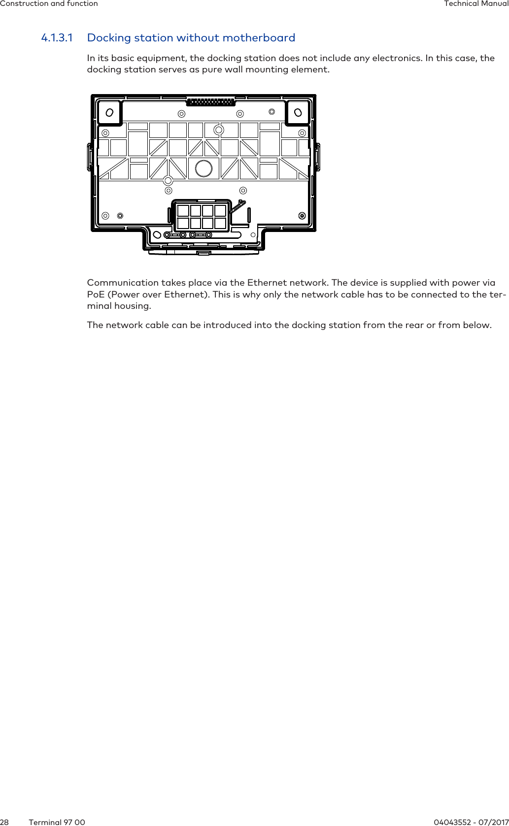
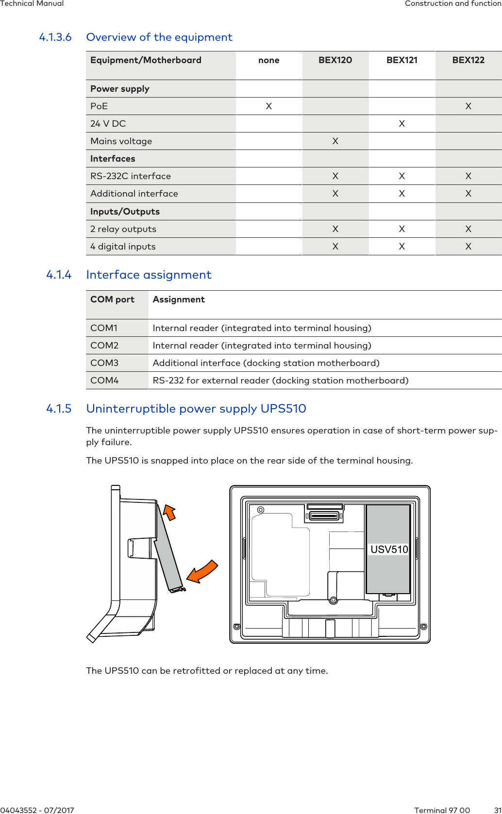
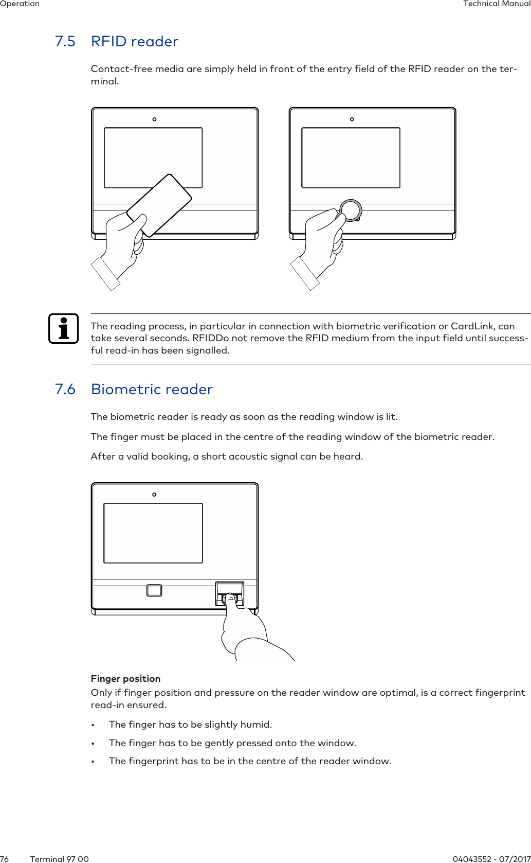
![About this document Technical Manual8 04043552 - 07/2017Terminal 97 001.4 Using the documentTo make it easier to find specific topics, please refer to the following document guidelines:• The contents list at the start of the document provides an overview of all topics.• The headings also list the relevant main chapter.• Cross-references provide the number of the chapter in which more information can befound. Example [ 5.7].• There is an alphabetical index at the end of the document.1.5 Additional documentationSpecific parametrization of the terminal software:• B-Client HR30 reference manualWeb interface for commissioning:• Service interface reference manualKaba ARIOS security concept and required system adjustments for different MIFARE media:• Kaba MIFARE adjustments reference manualSupplementary documentation is available on the Kaba website. Technical manuals can befound in a secured area of the website.• Access is only granted after a valid login.• An account must be set up before logging in for the first time.Opening login screen:1. Open your internet browser and go to http://www.kaba.com.2. Choose your language in the top right-hand corner of the screen.3. Under 'Products', choose either the 'Access Management' or 'Workforce Management'product division.4. In the top right-hand corner of the screen, click on the following symbol:5. Enter your email address and password to log in or create a new account (see below).ðThe technical manuals can be found under 'Downloads'.Creating an account:1. Click 'Create account'.2. Fill in the data fields and confirm your entries.ðA confirmation link will be sent to your email address.3. Click on the confirmation link in your email to activate your account.](https://usermanual.wiki/dormakaba-EAD/LEGMRD/User-Guide-3629599-Page-8.png)
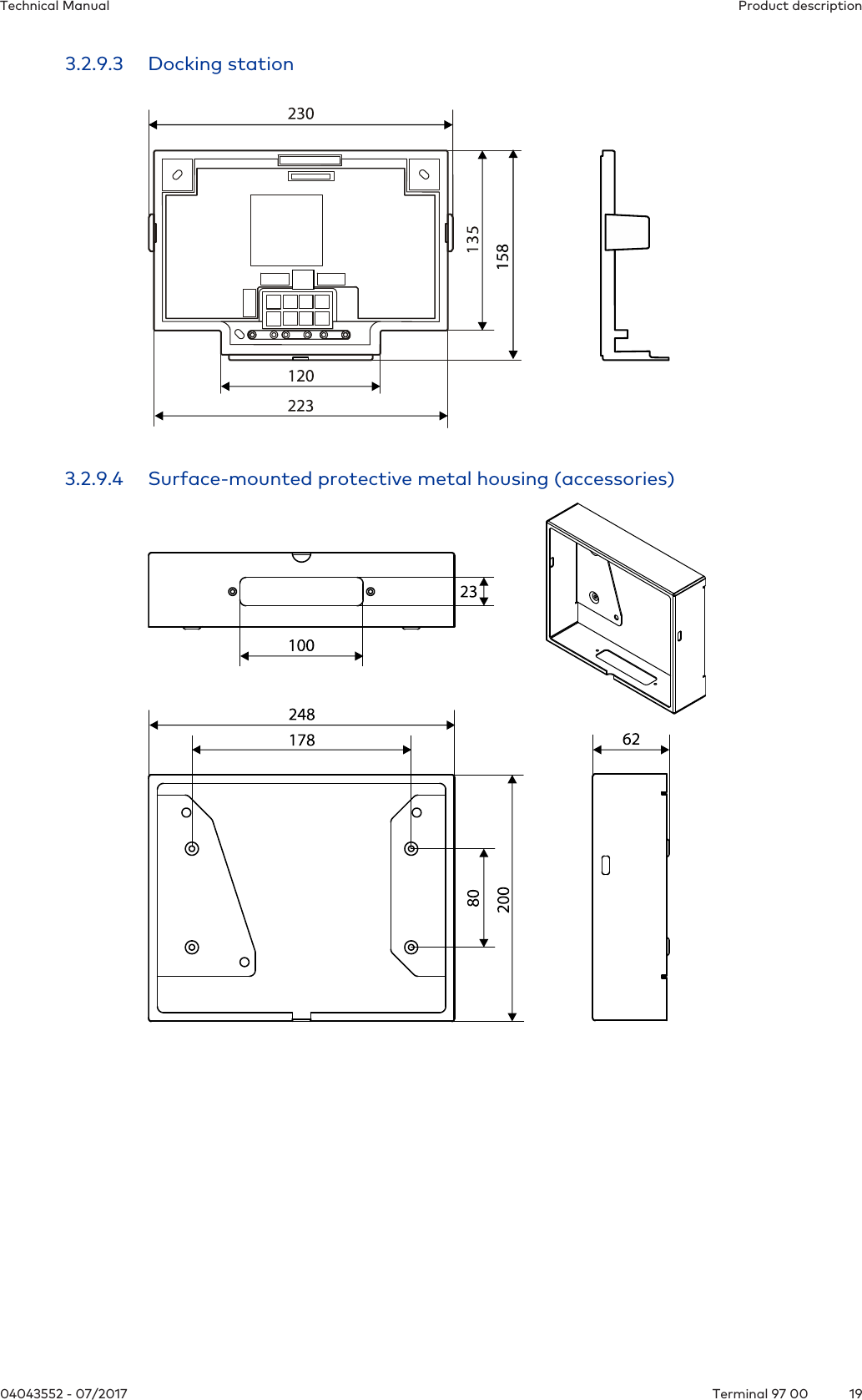
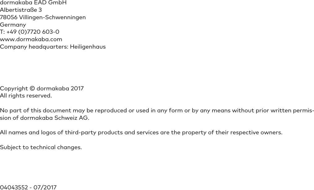
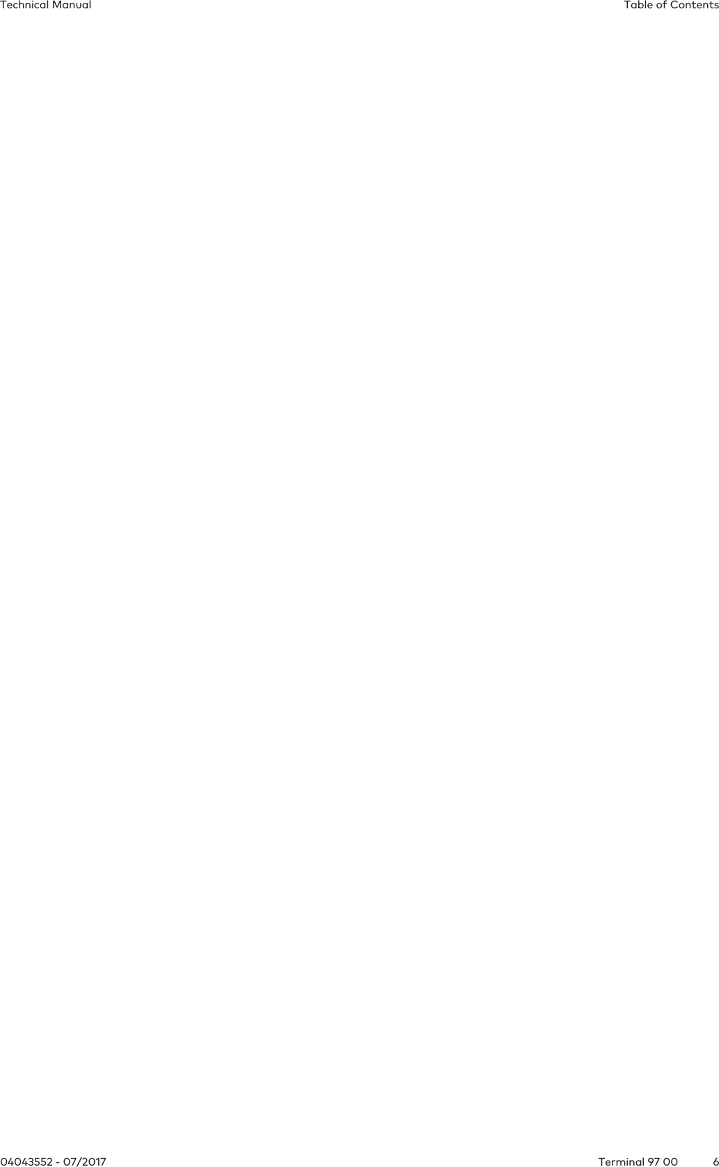
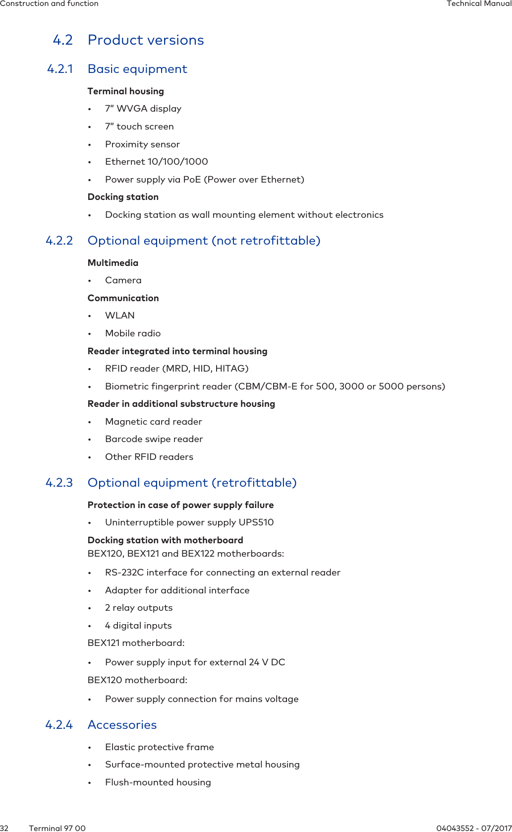
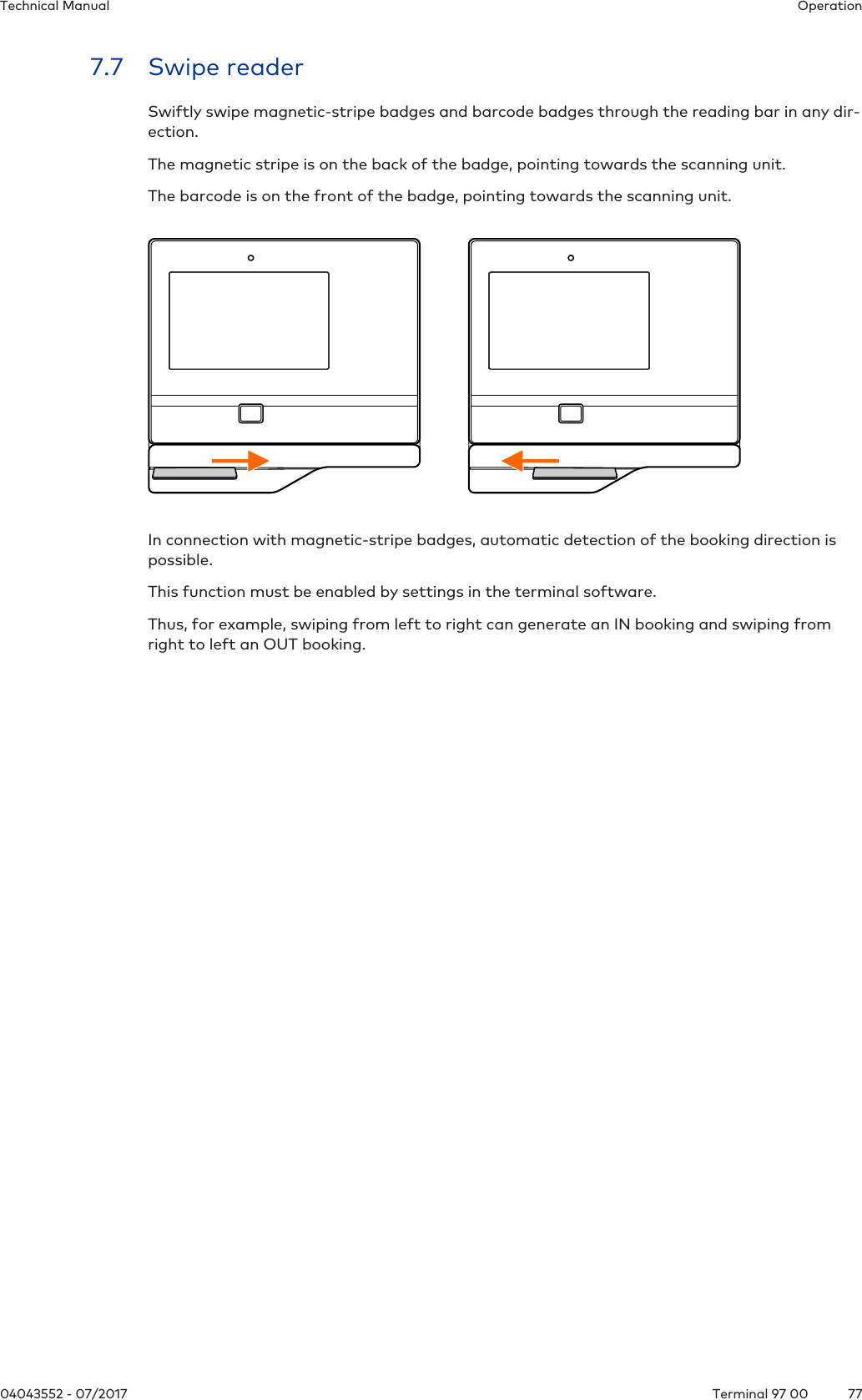
![Product descriptionTechnical Manual2104043552 - 07/2017 Terminal 97 003.3 ConformityThis product conforms to the following standards:EN 62368-1:2014 EN 55032:2015EN 55024+A1:2015according to the provisions of the EU directives2014/35/EU - Low Voltage Directive (LVD)2014/30/EU - Electromagnetic Compatibility (EMC)The RFID readers MRD (LEGIC & MIFARE) and HID iCLASS SE / Prox used in this productcomply with the following standardsEN 300330-2 V1.6.1EN 301489-3 V1.6.1according to the provisions of the EU directive2014/53/EU - Radio Equipment Directive (RED)RoHS This device complies with the regulations of the Directive 2011/65/EU of the European Parlia-ment and of the Council of June 8, 2011, on the restriction of the use of certain hazardoussubstances in electrical and electronic equipment.The original declaration of conformity can be downloaded in PDF format from www.kaba.com/conformity.In addition, the product also complies with the following standardsUL62368-1:2014-12CAN/CSA-22.2 No. 62368-1:2014-12 FCC Code of Federal Regulations, CFR 47, Part 15, Sections 15.107 and 15.109 (Class B) IC Industry Canada Radio Standards Specifications ICES-003 Issue 5, Sections 5(a)(i) and 5(b)(i) Class B (ITE)The RFID readers MRD (LEGIC & MIFARE) and HID iCLASS SE / Prox used in this productcomply with the following standardsFCC Code of Federal Regulations, CFR 47, Part 15, Sections 15.207, 15.209, 15.215 and 15.225 IC Industry Canada Radio Standards Specifications RSS-GEN Issue 4, Sections 8.8, 8.9, 8.10 andRSS-210 Issue 8, Section A2.6 (Category I Equipment) FCC § 15.19This device complies with Part 15 of the FCC rules. Operation is subject to the following twoconditions: (1) This device may not cause harmful interference, and (2) this device must acceptany interference received, including interference that may cause undesired operation.FCC § 15.21 (Warning Statement)[Any] changes or modifications not expressly approved by the party responsible for compli-ance could void the user’s authority to operate the equipment.FCC § 15.105Note: This equipment has been tested and found to comply with the limits for a Class A di-gital device, pursuant to part 15 of the FCC Rules. These limits are designed to provide reas-onable protection against harmful interference when the equipment is operated in a commer-cial environment. This equipment generates, uses, and can radiate radio frequency energyand, if not installed and used in accordance with the instruction manual, may cause harmful](https://usermanual.wiki/dormakaba-EAD/LEGMRD/User-Guide-3629599-Page-21.png)
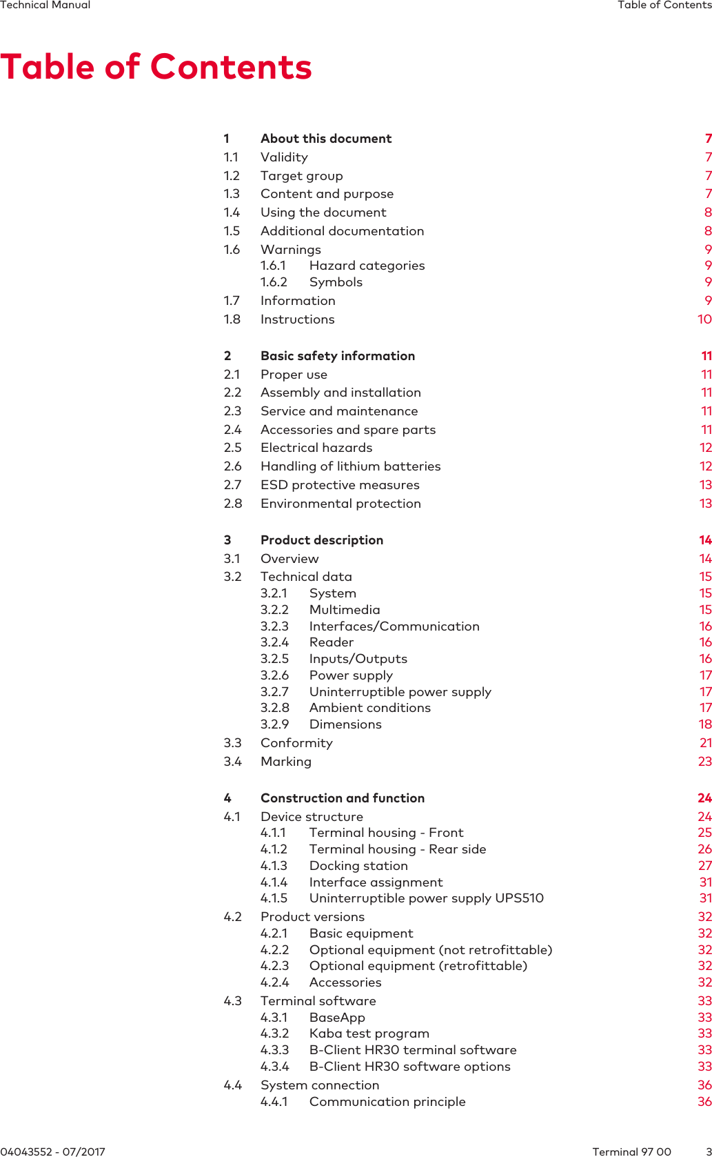
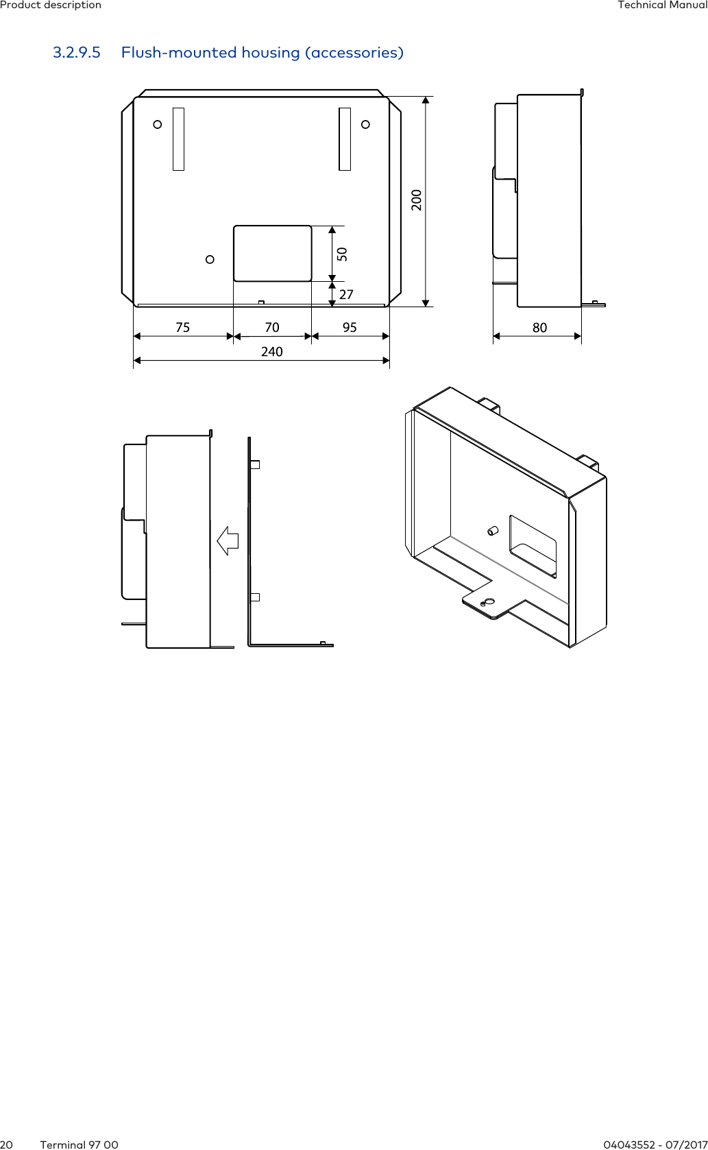
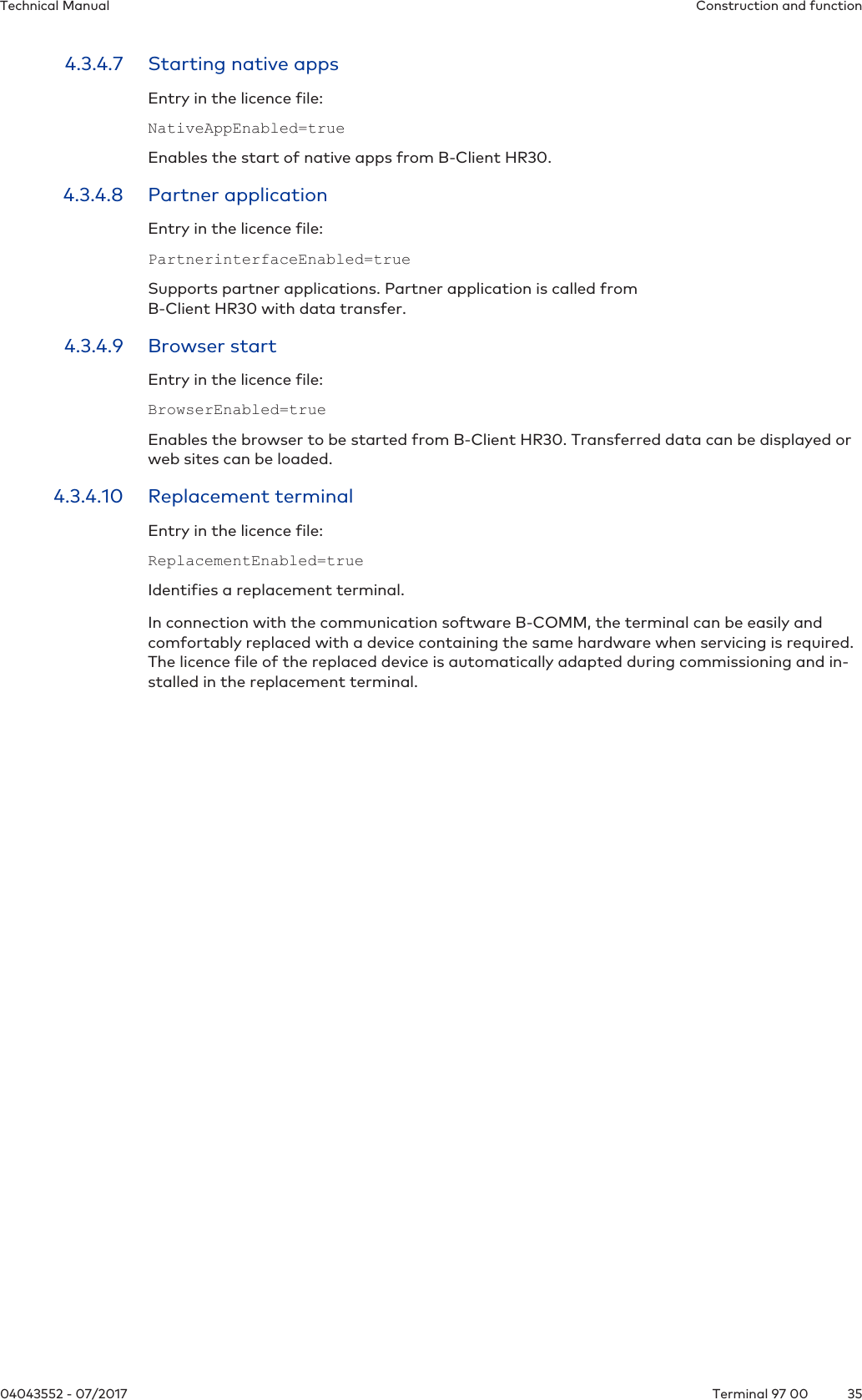
![Construction and functionTechnical Manual3304043552 - 07/2017 Terminal 97 004.3 Terminal software4.3.1 BaseAppThe BaseApp is the user interface of the android-based terminal. The BaseApp is part of thebasic equipment and forms the platform for all applications (apps) used on the terminal.The BaseApp essentially performs the following functions:• Protection of the operating system from unauthorized access (system isolation). Onlycontrolled access to the android operating system is possible.• Organization and start-up of applications (apps).• Provision of functions and interfaces for access to the hardware.• Provision of service functions via a web interface (service interface) for commissioningand maintenance of the device.4.3.2 Kaba test programThe Kaba test program application (TP) has already been installed on the terminal ex works.The test program app offers the following functions:• Adjustment of various system settings locally to the device• Retrieval of system information• Testing of individual system components4.3.3 B-Client HR30 terminal softwareThe B-Client HR30 terminal software allows the device to be used as time and attendanceterminal.The B-Client HR30 terminal software makes the device compatible in terms of data recordswith terminals of the B-web and B-net series, allowing it to be connected to the host systemvia the communication software B-COMM.4.3.4 B-Client HR30 software optionsThe usable range of functions of the device is given by the options activated in the 'sop.ini’ li-cence file by means of the corresponding licence key.Some software options require an appropriate hardware equipment.Upon purchasing an additional software option later on, the existing licence file must be re-placed with the new extended licence file.The sop.ini is located in the following directory/data/data/com.kaba.apps.hr/files/init.From the parameters, you can determine which functions are active.The relevant parameters are located in the [BClientHR30] section.Each parameter has the value true or false.](https://usermanual.wiki/dormakaba-EAD/LEGMRD/User-Guide-3629599-Page-33.png)
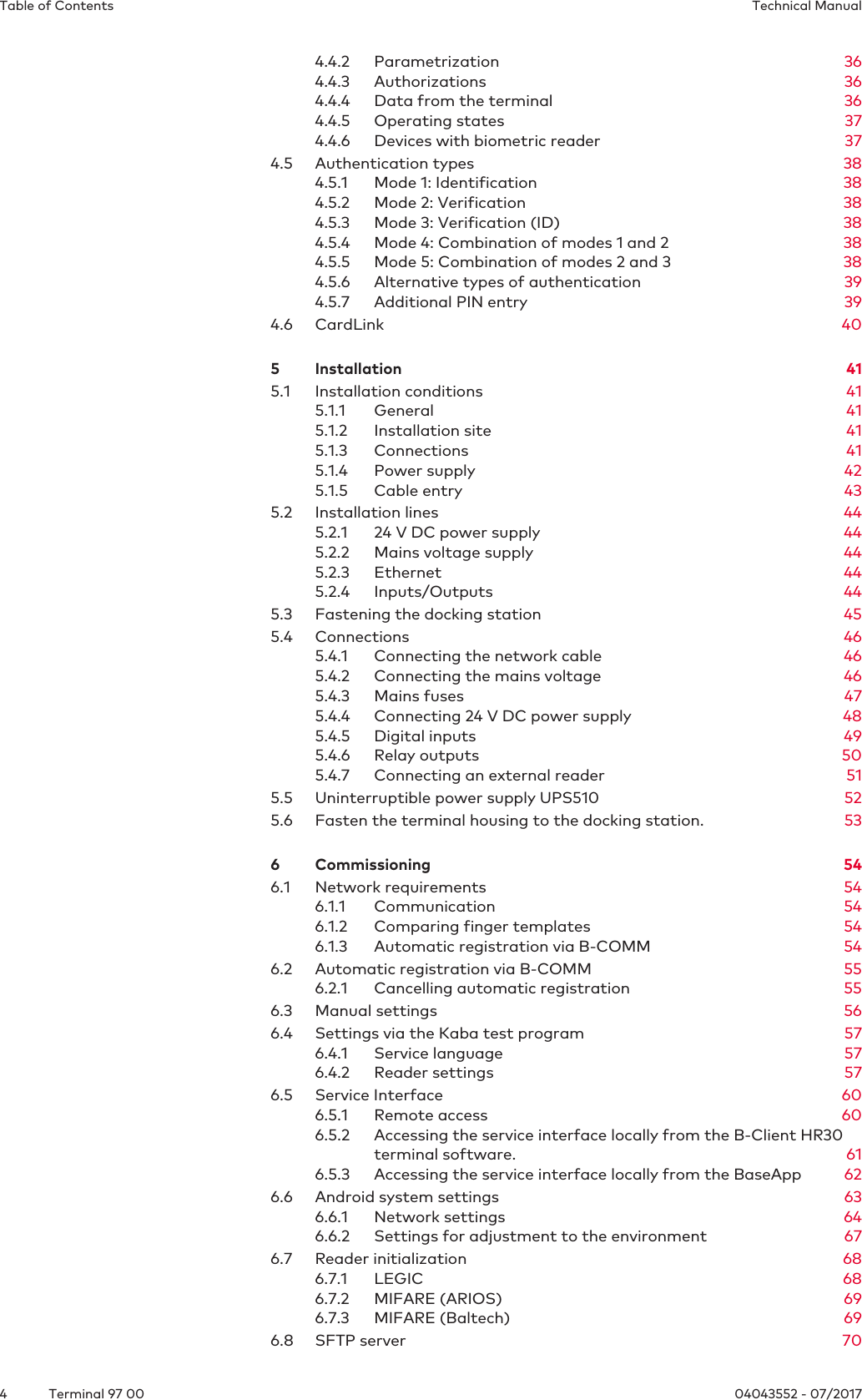
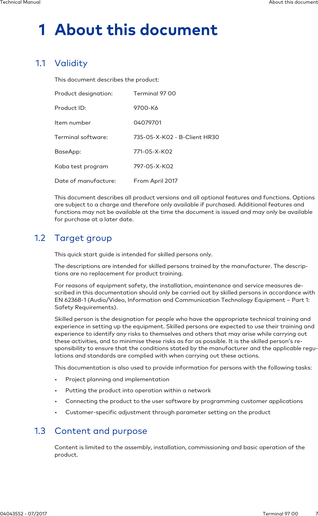
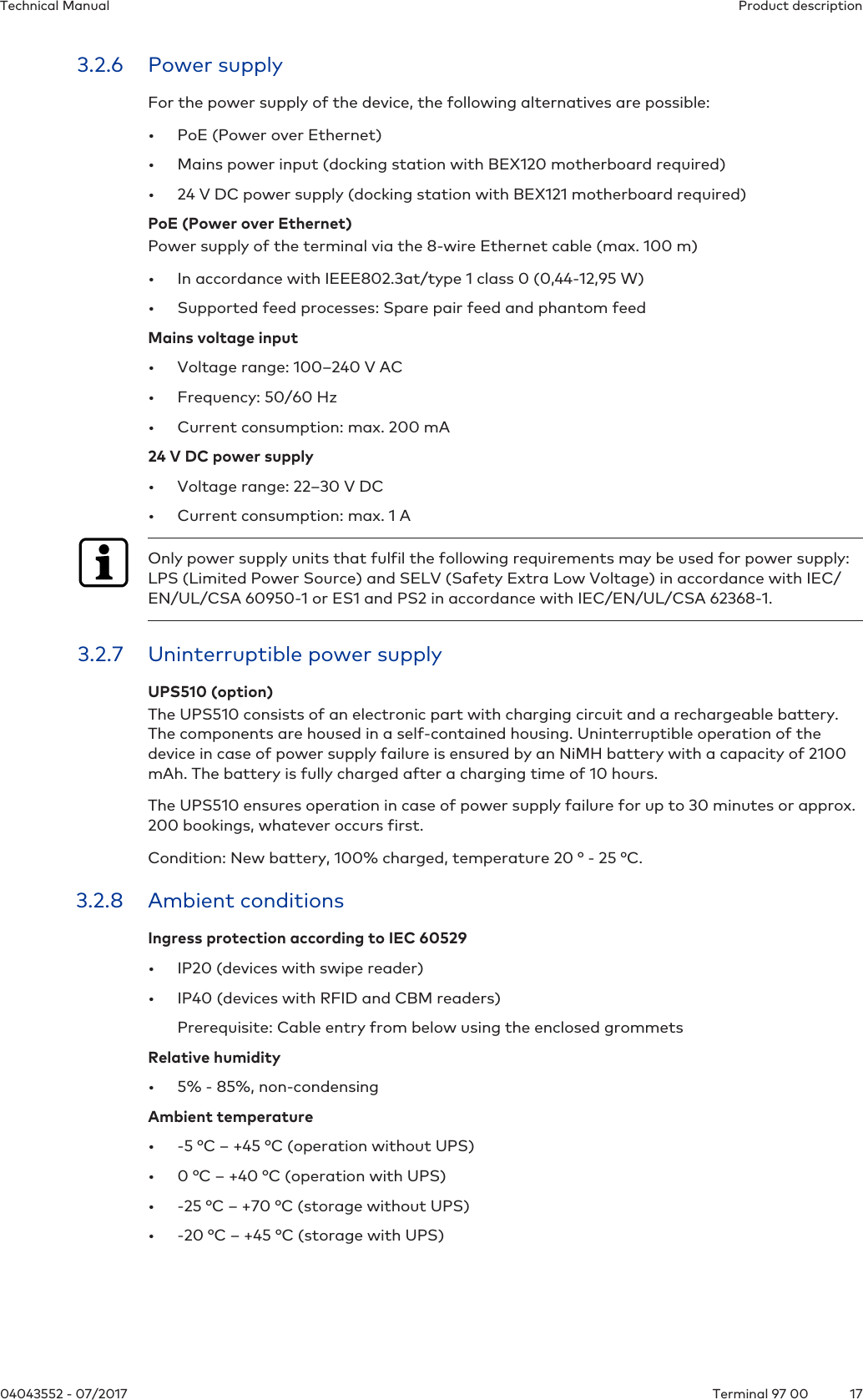
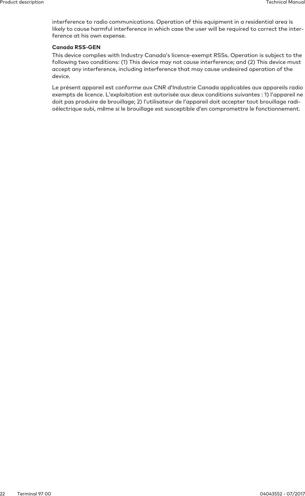
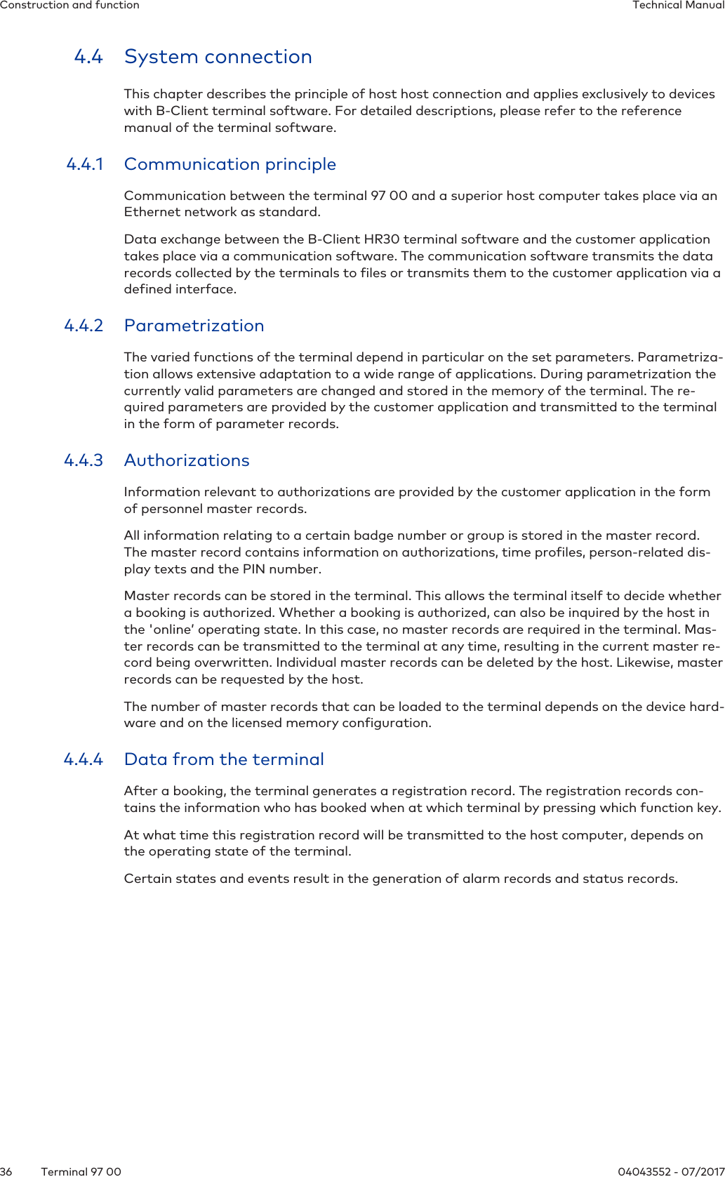
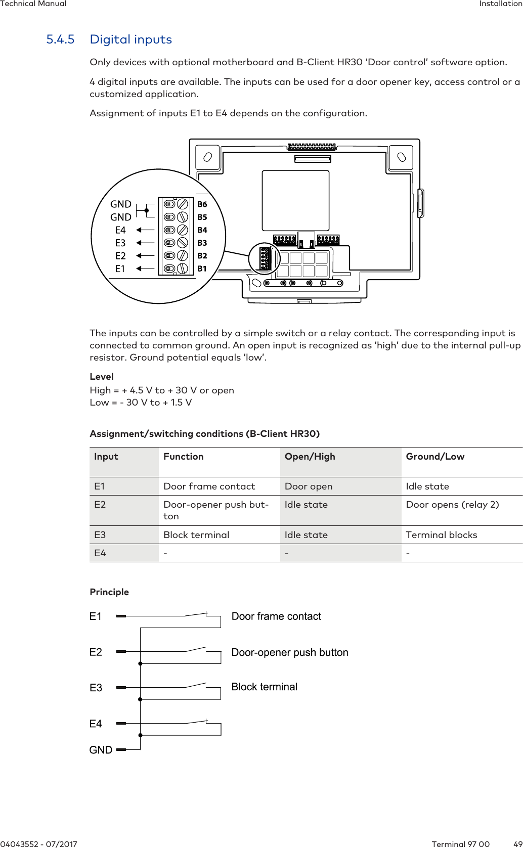
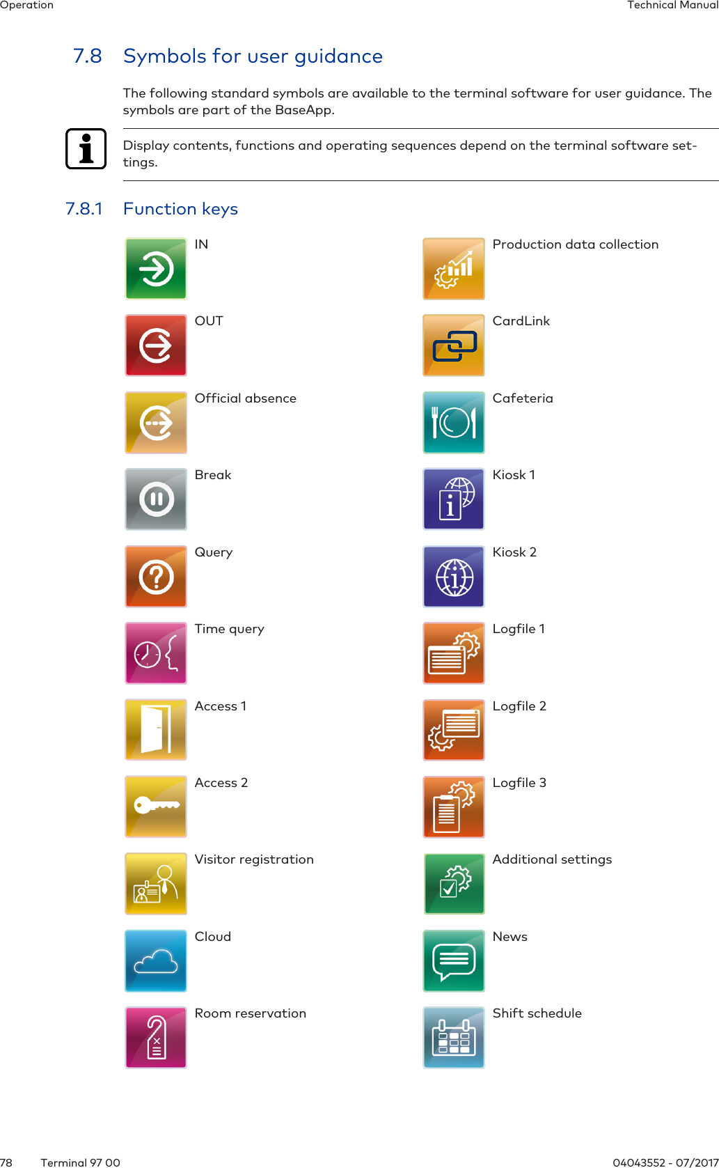
![Construction and function Technical Manual34 04043552 - 07/2017Terminal 97 004.3.4.1 Licence for the B-Client HR30 terminal software.Entry in the licence file:[BClientHR30]BClientHR30Enabled=true4.3.4.2 CardLinkEntry in the licence file:CardLinkEnabled=trueEnables CardLink update and CardLink validation in connection with LEGIC or MIFARE read-ers.4.3.4.3 Data encryptionEntry in the licence file:EncryptionEnabled=trueData encryption via Ethernet UDP in connection with the communication software B-COMM.Data encryption via HTTPS with XML communication.4.3.4.4 Door controlEntry in the licence file:AccessControlEnabled=trueHardware prerequisite: Docking station with motherboardEnables:• Use of 4 inputs for door surveillance and door opening.• Use of 2 relay outputs for door opening or break signal control• Check for time profiles:• PIN check.• Check for double access.4.3.4.5 LocalEnrollmentEntry in the licence file:LocalEnrollmentEnabled=trueEnables the registration of new fingerprints via the biometric reader locally at the terminal.4.3.4.6 Memory optionsEntry in the licence file (possible values: 0, 1, 2, 3, 4):BufferConfiguration=The following overview shows the maximum possible number of data records in the respectivememory option.Record type/Option 0 1 2 3 4* 4Master records 200 1,000 2,000 10,000 30,000 50,000Registration records 10,000 10,000 10,000 10,000 30,000 50,000Update records* 400 2,000 4,000 20,000 60,000 -Validation records* 200 1,000 2,000 10,000 30,000 -*in connection with CardLink](https://usermanual.wiki/dormakaba-EAD/LEGMRD/User-Guide-3629599-Page-34.png)
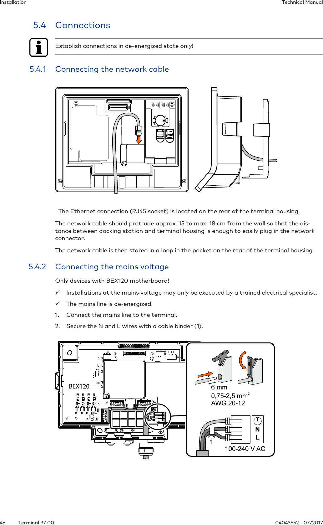
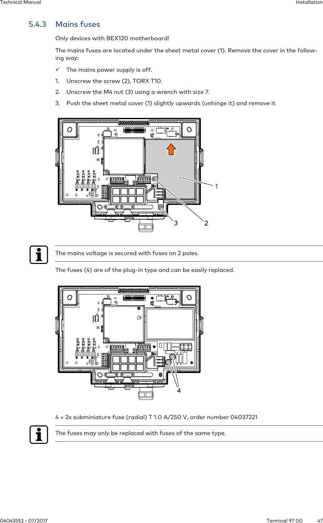
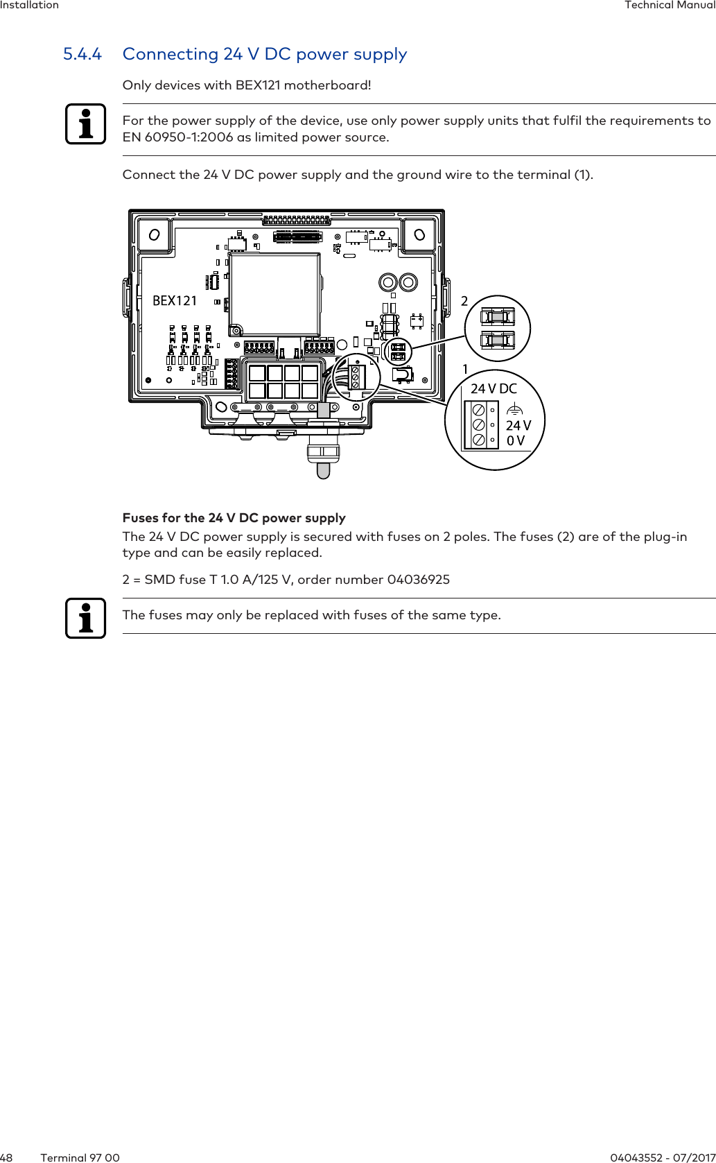
![Installation Technical Manual42 04043552 - 07/2017Terminal 97 005.1.4 Power supply5.1.4.1 PoE power supplyFor PoE power supply [}3.2.6], a PSE (Power Sourcing Equipment) must be provided on thenetwork cable for power feeding.Possible methods for feeding the power supply via the PSE:• End span (direct supply, e.g. via PoE switch)• Midspan (supply via intermediate sources, e.g. PoE injector)5.1.4.2 24 V DC power supplyDevices with docking station equipped with BEX121 motherboard. It has a 24 V DC input withovervoltage protection and transient filter for supplying power to the terminal.Only power supply units that fulfil the following requirements may be used for power supply:LPS (Limited Power Source) and SELV (Safety Extra Low Voltage) in accordance with IEC/EN/UL/CSA 60950-1 or ES1 and PS2 in accordance with IEC/EN/UL/CSA 62368-1.5.1.4.3 Mains voltage supplyOnly devices with docking station equipped with BEX120 motherboard. It has a 100-240 V ACmains voltage input and an integrated limited power source power supply unit (LPS).The mains voltage supply can be designed as stationary wiring or as separable connection.For the terminal, a separate fuse-protected circuit must be provided. If the mains voltagesupply is designed as a separable connection, the following applies:• The mains socket with grounded contact must be in the immediate vicinity of the device.• The mains plug must be freely accessible.If the mains voltage supply is designed as stationary wiring, the following applies:• An easily accessible circuit breaker must be provided.• The circuit breaker (LS) must be designed for max. 10 A.• The electrical system of the building must be equipped with an all-pole supply circuitswitch.](https://usermanual.wiki/dormakaba-EAD/LEGMRD/User-Guide-3629599-Page-42.png)
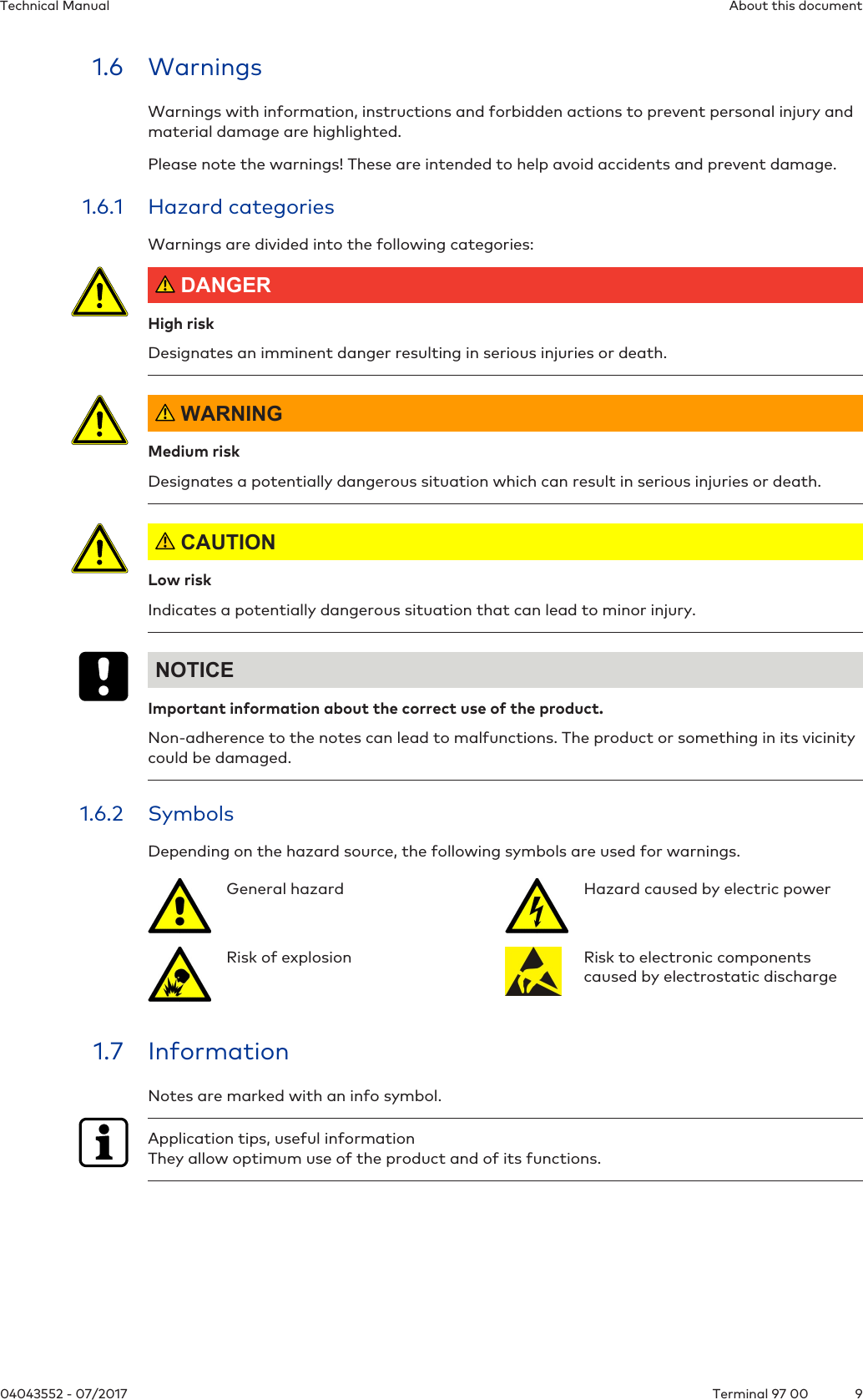
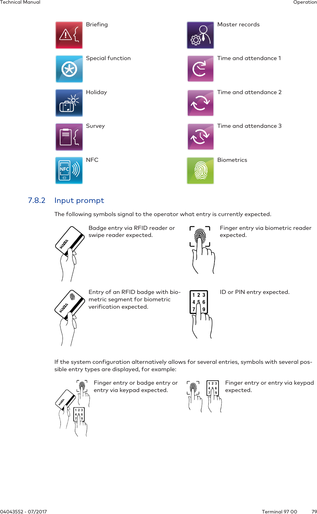
![InstallationTechnical Manual5104043552 - 07/2017 Terminal 97 005.4.7 Connecting an external readerOnly devices with optional motherboard!An additional external reader, for example a CCD barcode scanner, can be connected to thedevice.The reader can be connected to the COM4 port of the device. Further hardware and softwareoptions are not required.To ensure correct function, the reader must be configured and activated via the Service inter-face [}6.5] or the Kaba test program [}6.4.2].1 RJ45 connection for reader with RS-232C levels. The barcode scanners provided by Kaba as accessories work with RS232C levels.2 Fuse for the power supply of the external reader, SMD fuse T375 mA, order number 04107874Assignment of the RJ45 socket (1)181 5 V DC; max. 300 mA 5 TxD (of the reader)2 - 6 -3 GND 7 -4 - 8 -Hardware handshake is not supported, no transmission delay for scanner data, communica-tion parameters: 9600, 8, N, 1 (can be set).Power supply for the readerThe power supply of the external reader can take place via the 5 V DC of the RJ45 socket. Themaximum allowed current is 300 mA.](https://usermanual.wiki/dormakaba-EAD/LEGMRD/User-Guide-3629599-Page-51.png)
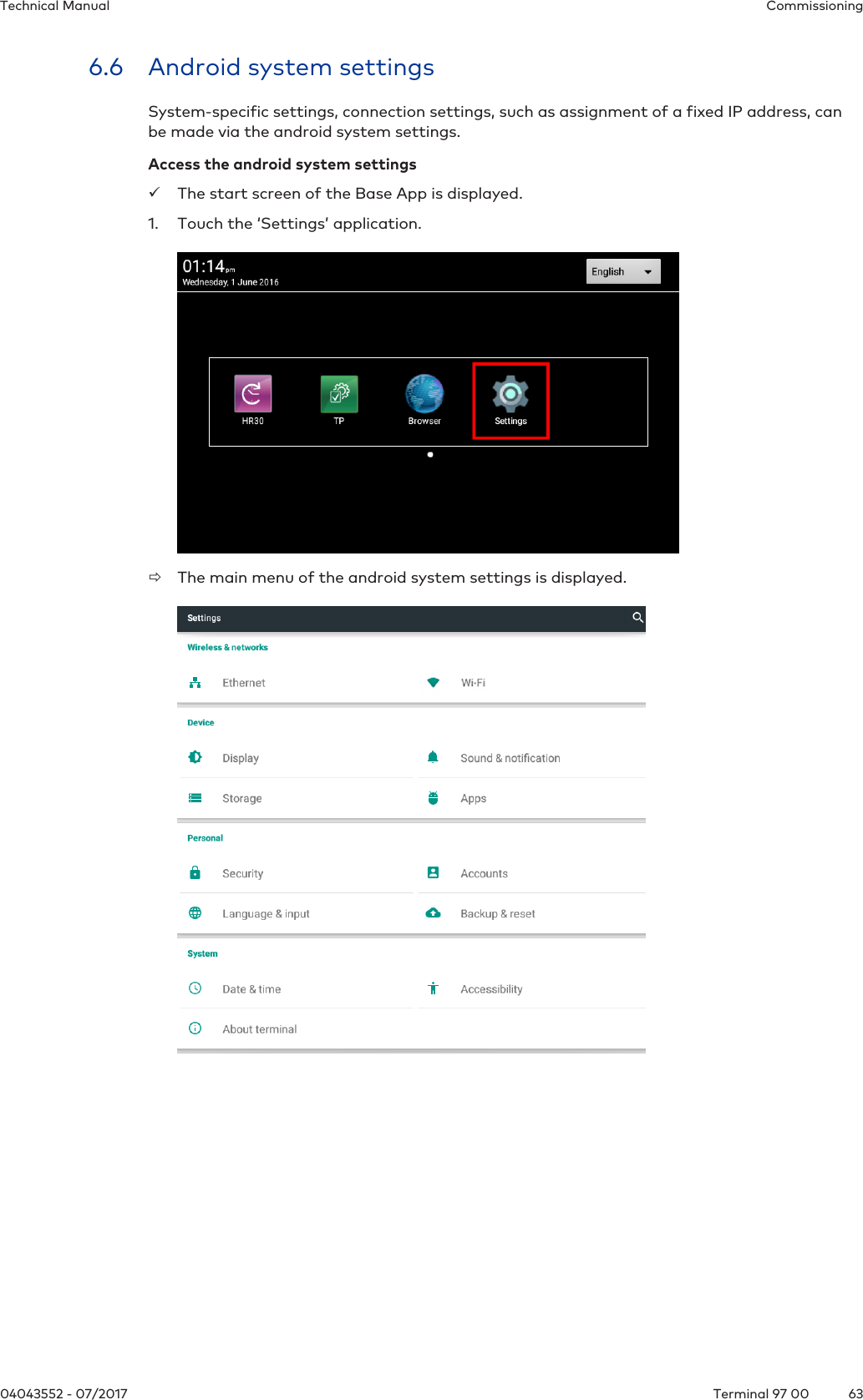
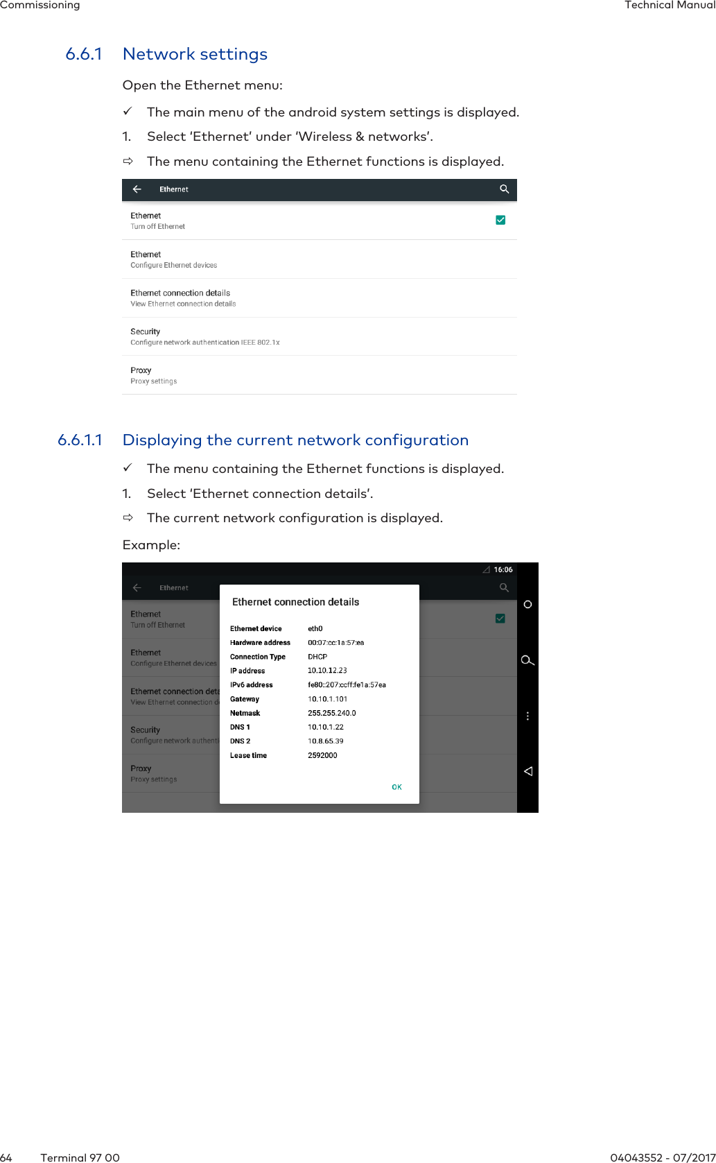
![Commissioning Technical Manual56 04043552 - 07/2017Terminal 97 006.3 Manual settingsConfiguration and parameter setting of the terminal are done largely via the B-COMM communication software.Manual settings can be made locally on the device or from a remote location.Settings locally on the device:• Settings via the Service interface [}6.5]• Settings via the Kaba test program [}6.4]• Android system settings [}6.6]Options for making settings from a remote location:• Remote setup [}6.9]• Service Interface [}6.5]Network settingsTo change network settings, for example assignment of a fixed terminal IP address, the fol-lowing options are available:• Locally on the device via Android system settings [}6.6]• Locally on the device via Service interface [}6.5]• Remote via the Service interface [}6.5]Condition: The device must already have an IP address, which must be known.](https://usermanual.wiki/dormakaba-EAD/LEGMRD/User-Guide-3629599-Page-56.png)
![CommissioningTechnical Manual5704043552 - 07/2017 Terminal 97 006.4 Settings via the Kaba test programThe Kaba test program is in general installed on the device. Apart from various test and infofunctions, the Kaba test program also offers the option to make system-specific settings,such as the configuration of the readers.Loading the settings of the Kaba test programüThe start screen of the Base App [}7.9] is displayed.1. Touch the icon designated ‘TP’.ðThe Kaba test program is started.2. Select ‘Settings’.ðThe settings of the Kaba test program are displayed.6.4.1 Service languageThis function allows you to select the language for service texts and the Kaba test program.6.4.2 Reader settingsConfiguration of the internally and externally connected readers.These reader settings correspond to the device configuration at the time of delivery. The func-tion is usually only required if an external reader is connected at a later stage or if LEGIC isswitched over to MIFARE in connection with an MRD reader.](https://usermanual.wiki/dormakaba-EAD/LEGMRD/User-Guide-3629599-Page-57.png)
![CommissioningTechnical Manual6104043552 - 07/2017 Terminal 97 006.5.2 Accessing the service interface locally from the B-Client HR30terminal software.Access the service interface from the B-Client HR30 terminal softwareüB-Client HR30 terminal software has been started [}7.9.1] and is in the Basic view.1. Touch the Back icon in the navigation bar [}7.4].By default, the actuating time is 4 seconds, but can be adjusted to between 1 and 15seconds.ðAfter the set actuating time has expired, the password prompt appears.2. Enter a password or leave the field empty if no password has been stored.NOTE: No password has been stored for the device in its delivery state. A password can beassigned using the parameter records X02/X12. See reference manual of the terminalsoftware.3. Press ‘OK’ to confirm.NOTICE! Three invalid password entries will lock the dialog. It must then be unlocked viathe parameter record I2.4. Select ‘Settings’.ðThe start page of the service interface appears on the display.Without any touch interaction, the service interface will be automatically closed again after 3minutes.](https://usermanual.wiki/dormakaba-EAD/LEGMRD/User-Guide-3629599-Page-61.png)
![Commissioning Technical Manual62 04043552 - 07/2017Terminal 97 006.5.3 Accessing the service interface locally from the BaseAppAccess the service interface from the BaseApp.üThe start screen of the Base App is displayed.1. Touch the Back icon in the navigation bar [}7.4].ðA menu appears in the lower display area2. Touch ‘Preferences’ðA BaseApp function selection is displayed.3. Touch 'Launch Service Interface' under Service Interface.ðThe start page of the service interface appears on the display.Without any touch interaction, the service interface will be automatically closed again after 3minutes.](https://usermanual.wiki/dormakaba-EAD/LEGMRD/User-Guide-3629599-Page-62.png)
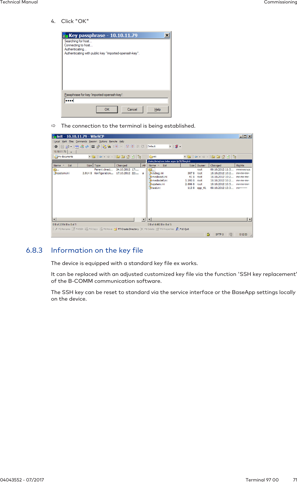
![CommissioningTechnical Manual7304043552 - 07/2017 Terminal 97 006.9 Remote setupThe following settings can also be transferred to the device via SFTP [}6.8]:• Host configuration• FTCS host configuration• Reader settingsThis type of start-up should only be carried out by experienced system specialists.Procedure:1. Establish SFTP connection to the device.2. Load the following file in ASCII mode to the local computer: /data/data/com.kaba.apps.hr/files/EEPROMsettingThis file contains the parameter used for the last start.3. Rename file to reboot.cmd.4. Adjust the parameter values in the file accordingly.NOTE: Changes in the sections [General] and [Ethernet] will not be applied!5. Enter ‘RESET’ in the first line of the file. Example:RESET [Ethernet] MAC Addr=00:07:cc:00:62:e4 Terminal Addr=10.10.5.85...6. Copy the reboot.cmd file to the following directory on the device: /data/data/com.kaba.apps.hr/files/transfer/ðThe file will be identified within approx. 15 seconds and the parameter values will be ap-plied.ðThe terminal software is then restarted with the changed settings.](https://usermanual.wiki/dormakaba-EAD/LEGMRD/User-Guide-3629599-Page-73.png)
![OperationTechnical Manual8304043552 - 07/2017 Terminal 97 007.9.2 App managementThis function determines which applications (apps) are displayed on the start screen and arethus available to the operator. The order of the app icons can also be adjusted.In addition, a default application started automatically with the system can be defined.Starting app administrationüThe start screen of the Base App is displayed.1. Touch the Back icon in the navigation bar [}7.4].2. Select ‘Preferences’.3. Select ‘App management’.ðThe submenu of the app management is displayed.](https://usermanual.wiki/dormakaba-EAD/LEGMRD/User-Guide-3629599-Page-83.png)
![OperationTechnical Manual8504043552 - 07/2017 Terminal 97 007.9.3 System InformationThe BaseApp menu can be used to display miscellaneous system information.Displaying system InformationüThe start screen of the Base App is displayed.1. Touch the Back icon in the navigation bar [}7.4].2. Select ‘System Information’.ðThe system information is displayed.](https://usermanual.wiki/dormakaba-EAD/LEGMRD/User-Guide-3629599-Page-85.png)
![Operation Technical Manual86 04043552 - 07/2017Terminal 97 007.10 B-Client HR30 terminal software7.10.1 Starting the terminal softwareIn the start screen of the BaseApp [}7.9], the available applications (apps) are displayed.Touch the icon designated ‘HR30’ to start the B-Client HR30 terminal software.The B-Client HR30 user interface is shown on the display of the terminal.The appearance of the device software can be adjusted specifically for each customer and istherefore variable. Accordingly, the default user interface shown above must be considered anexample.](https://usermanual.wiki/dormakaba-EAD/LEGMRD/User-Guide-3629599-Page-86.png)
![OperationTechnical Manual8704043552 - 07/2017 Terminal 97 007.10.2 Shutting down the terminal softwareShut down the B-Client terminal software as follows:1. Touch the Back icon in the navigation bar [}7.4].NOTE: By default, the actuating time is 4 seconds, but can be adjusted to between 1 and15 seconds.ðAfter the set actuating time has expired, the password prompt appears.2. Enter a password or leave the field empty if no password has been stored.NOTE: No password has been stored for the device in its delivery state. A password can beassigned using the parameter records X02/X12. See reference manual of the terminalsoftware.3. Press ‘OK’ to confirm.NOTICE! Three invalid password entries will lock the dialog. It must then be unlocked viathe parameter record I2.ðThe terminal software is shut down, and the BaseApp user interface [}7.9] is displayed.](https://usermanual.wiki/dormakaba-EAD/LEGMRD/User-Guide-3629599-Page-87.png)
![Operation Technical Manual88 04043552 - 07/2017Terminal 97 007.10.3 Info functionsIn the menu of the B-Client HR30 terminal software, two info functions are available.üB-Client HR30 terminal software has been started. [}7.10.1]1. Touch the Menu icon in the navigation bar [}7.4].ðAfter the set actuating time has expired, the password prompt appears.NOTE: By default, the actuating time is 4 seconds, but can be adjusted to between 1and 15 seconds.2. Enter a password or leave the field empty if no password has been stored.NOTE: No password has been stored for the device in its delivery state. A password can beassigned using the parameter records X02/X12. See reference manual of the terminalsoftware.3. Press ‘OK’ to confirm.ðThe menu is displayed.Host communicationThe following information is displayed:• B-Client HR30 version• Terminal IP address• Host IP address and port• Group identification and device identification• Current readersNetwork communicationThe following information is displayed:• Terminal IP address• Network mask• MAC address• DNS• Gateway• DHCP server address](https://usermanual.wiki/dormakaba-EAD/LEGMRD/User-Guide-3629599-Page-88.png)
![OperationTechnical Manual8904043552 - 07/2017 Terminal 97 007.10.4 Registering new fingerprints at the terminalThe function ‘Local Enrollment’ of the B-Client HR30 terminal software allows new finger-prints to be registered via the biometric reader at the terminal.Prerequisites:• Terminal with biometric reader• B-Client HR30 terminal software with ‘Local Enrollment’ software option7.10.4.1 Displaying the functionüB-Client HR30 terminal software has been started [}7.10.1].1. Touch the Menu icon in the navigation bar [}7.4].ðAfter the set actuating time has expired, the password prompt appears.NOTE: By default, the actuating time is 4 seconds, but can be adjusted to between 1and 15 seconds.2. Enter a password or leave the field empty if no password has been stored.NOTE: No password has been stored for the device in its delivery state. A password can beassigned using the parameter records X02/X12. See reference manual of the terminalsoftware.3. Press ‘OK’ to confirm.4. Select 'Local Enrollment'.ðThe main menu is displayed. The biometric mode and the current assignment of the in-ternal reader database are additionally displayed.](https://usermanual.wiki/dormakaba-EAD/LEGMRD/User-Guide-3629599-Page-89.png)
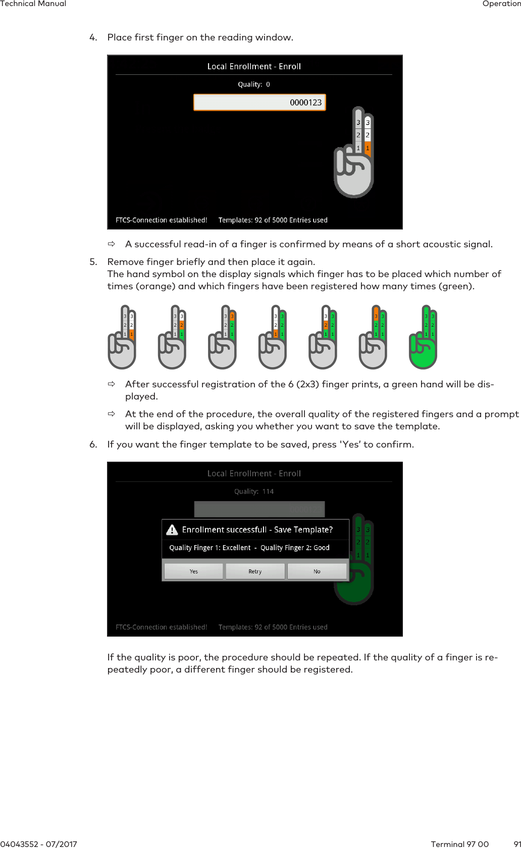
![Operation Technical Manual90 04043552 - 07/2017Terminal 97 007.10.4.2 EnrollThis function allows persons to be registered via the biometric reader of the terminal. The fin-gerprints are stored in the internal reader database.Operation with biometric softwareDuring normal operation with biometric software, the new finger templates are synchronizeddirectly using the Finger Template Control Service (FTCS).The function 'Enroll’ is only executed if an FTCS connection is already available via the BCFTCstream.Standalone modeIn standalone mode, the function is also executed without FTCS connection.Procedure2 fingers per person are registered. 3 pictures are taken of each finger. To do so, each fingerhas to be briefly placed on the reader window three times. A quality value is specified for eachregistration process.The quality of the registered fingers is subdivided into three levels.Quality of number Quality of text> 120 very good60-120 good< 60 poorOptimal finger positionIf the finger position is not ideal during enrollment, symbols to that effect are shown on thedisplay [}7.8.5].Registering a person1. Select 'Enroll'.2. Enter template ID.NOTE: The person is identified by means of the template ID. The length of the ID is presetby the 'PresetEnroll' parameter.3. Press 'OK’ to confirm the template ID.](https://usermanual.wiki/dormakaba-EAD/LEGMRD/User-Guide-3629599-Page-90.png)
![MaintenanceTechnical Manual9304043552 - 07/2017 Terminal 97 008 Maintenance8.1 Backup batteryTo back up the real-time clock RTC, the device is equipped with a lithium manganese dioxidebattery type CR2032.The battery is located on the rear side of the terminal housing.The backup battery must be replaced with a new one every 10years.8.1.1 Battery change CAUTIONLithium batteries can explode or burst explosively.Improper handling of lithium batteries may result in fires and explosions.• Replace lithium batteries only with batteries of the same type.• Do not open, drill through or squash lithium batteries.• Do not burn lithium batteries or expose them to high temperatures.• Do not short-circuit lithium batteries.• Do not recharge lithium batteries.1. Remove the terminal housing from the docking station.2. Remove UPS510 [}5.5] (if present)3. NOTE: Do not use tools such as a screwdriver and the like.Remove the old backup battery carefully by hand from the battery holder.4. Push the new battery into the holder until it snaps into place.5. Mount UPS510 (if present) again.6. Fasten the terminal housing again to the docking station.7. Reset terminal time.](https://usermanual.wiki/dormakaba-EAD/LEGMRD/User-Guide-3629599-Page-93.png)
![Maintenance Technical Manual94 04043552 - 07/2017Terminal 97 008.2 Replacement of the uninterruptible power supply UPS510To guarantee the buffer time as specified in the technical data, the uninterruptible powersupply UPS510 has to be replaced every 3years with a new one.Perform dismounting and mounting of the uninterruptible power supply UPS510 as described[}5.5].8.3 Cleaning the housingTo clean the housing, use a soft, lint-free cloth and a mild window cleaning agent!NOTICEOther agents may result in damage to the housing.Observe the following instructions in order to avoid producing damage to the housing and thereader window of the biometric reader (if present) during the cleaning process:• Do not use alcohol, such as ethanol and isopropanol• Do not use aggressive solvents• Do not use cleaning agents with added powder• Avoid scratching and abrasive movements](https://usermanual.wiki/dormakaba-EAD/LEGMRD/User-Guide-3629599-Page-94.png)
![MaintenanceTechnical Manual9504043552 - 07/2017 Terminal 97 008.4 Installation/Update of the terminal softwareFor the installation or update of the terminal software on the terminal, an installation tool isavailable. This so-called SFTP installer can be downloaded for the particular terminal soft-ware in the secured area of the dormakaba website (Extranet).InstallationFor initial installation or in order to replace a faulty installation, a complete installation of theterminal software is required.The installation process will reset any settings already made.UpdateAn update is performed in order to update the already existing terminal software to a newversion.During an update process, only the program files will be replaced. Existing settings are re-tained.8.4.1 Data backupBefore an update or a new installation of the terminal software is made, the following datamust be backed up.• Device configuration and parametrization• If specific layout adjustments are made, the 'interface.ini’ file and pictures must bebacked up on a local drive.8.4.2 Preparing installation/updateüAuthorization for access to dormakaba Extranet [}1.5].1. Download SFTP installer from dormakaba Extranet.2. Unzip ZIP file to a local directory.3. If the SSH key for SFTP access was changed: Copy relevant key file (*.ppk) to the directory of the SFTP installer. In the 'Standard_Software.ini' file, enter the file name of the key file under 'Key_Path='.Format Key_Path='<File name>.ppk'4. Start the installation tool by double-clicking 'SFTP Installer.exe'.ðThe first prompt of the user guidance is displayed.8.4.3 Performing an update1. Select the device type.2. Select 'Update’.3. Select terminal software (B-Client HR30)4. Select add-ons (BaseApp + test program)5. Enter IP address and SFTP access data.ðA summary of the installation data is displayed.6. Start process.ðThe process can take several minutes. Successful execution is confirmed by the install-ation tool.7. Restart the device.ðThe terminal software is now up-to-date.](https://usermanual.wiki/dormakaba-EAD/LEGMRD/User-Guide-3629599-Page-95.png)
![DisposalTechnical Manual9904043552 - 07/2017 Terminal 97 0010 Disposal This product complies with the WEEE directive and is, according to DIN EN standard 50419,marked with the WEEE symbol 'crossed-out wheeled bin’.The symbol refers to separate disposal of electric and electronic devices in EU countries.According to the European WEEE directive, the device must not be disposed of together withdomestic waste.The components of the device must be separately recycled or disposed of. Used devices con-tain valuable materials that must be recycled. Poisonous and dangerous components cancause lasting damage to the environment if disposed of improperly.According to the German Electrical and Electronic Equipment Act (ElektroG), the system op-erator has the duty to return electrical and electronic equipment at the end of their lifetimefree-of-charge to the manufacturer, point of sale or public collection points established forthis purpose.Disposal in Germany: At the end of use of the goods supplied, Kaba GmbH will take them back for a proper disposalin accordance with the legal regulations (German Electrical and Electronic Equipment Act,ElektroG). Charges incurred for transport to the manufacturer will be at the expense of theowner of the waste electrical equipment.Disposal in Switzerland:The equipment must be returned to an electrical equipment collection point according toVREG.In the EU, electrical and electronic equipment has to be disposed of according to national dis-posal and environmental legislation.Deletion of person-related dataIndividuals are responsible for the deletion of their personal data.Dispose of packaging in accordance with environmental regulations.The packaging materials can be recycled. Please do not dispose of the packaging with house-hold waste, instead send them for recycling.Lithium batteriesTo back up the real-time clock RTC, the device is equipped with a lithium manganese dioxidebattery type CR2032.The battery is located on the rear side of the terminal housing.Remove battery before returning the device [}8.1].Do not dispose of the batteries in your domestic waste.Used lithium batteries must be returned to a disposal system according to national and localregulations.To prevent short circuits and the resulting heating, lithium batteries must not be stored ortransported unprotected. Examples of suitable measures against short circuits include:• Placing the battery in a plastic bag• Covering poles with adhesive tapeSee also safety instructions in Handling of lithium batteries [}2.6].Uninterruptible power supply UPS510The device is optionally equipped with the uninterruptible power supply UPS510.The UPS510 contains an NiMH rechargeable battery.Remove UPS before returning the device [}5.5].](https://usermanual.wiki/dormakaba-EAD/LEGMRD/User-Guide-3629599-Page-99.png)