dormakaba EAD TT1100PRX Time and Attendance Terminal User Manual TT1100 Manual 08 2013 en
Kaba GmbH Time and Attendance Terminal TT1100 Manual 08 2013 en
UserManual.wiki
>
dormakaba EAD
>
TT1100PRX User Manual
User Manual
Navigation menu
Upload a User Manual
Namespaces
Wiki Guide
HTML
PDF
Info
Views
User Manual
Discussion / Help
Navigation


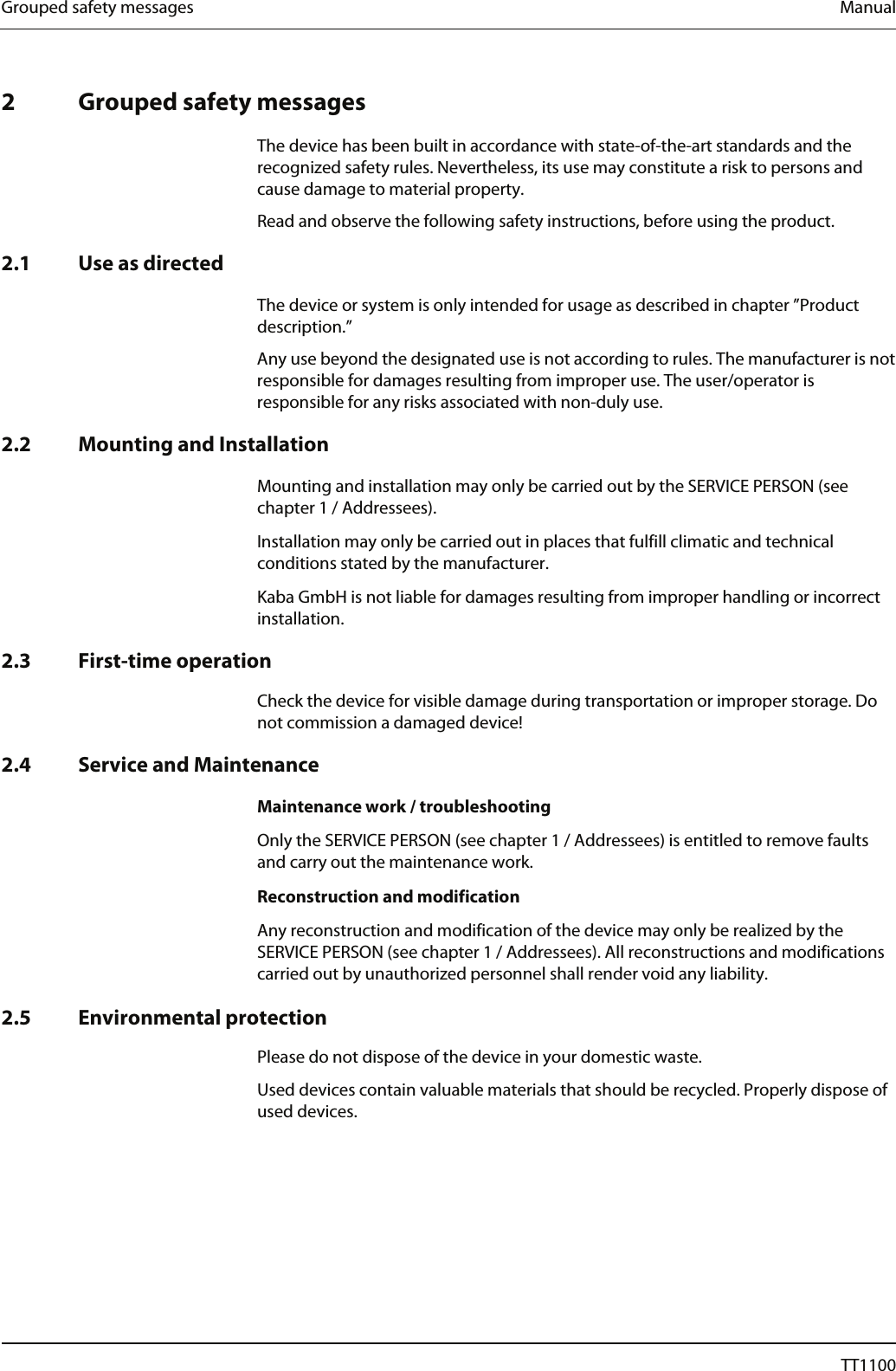

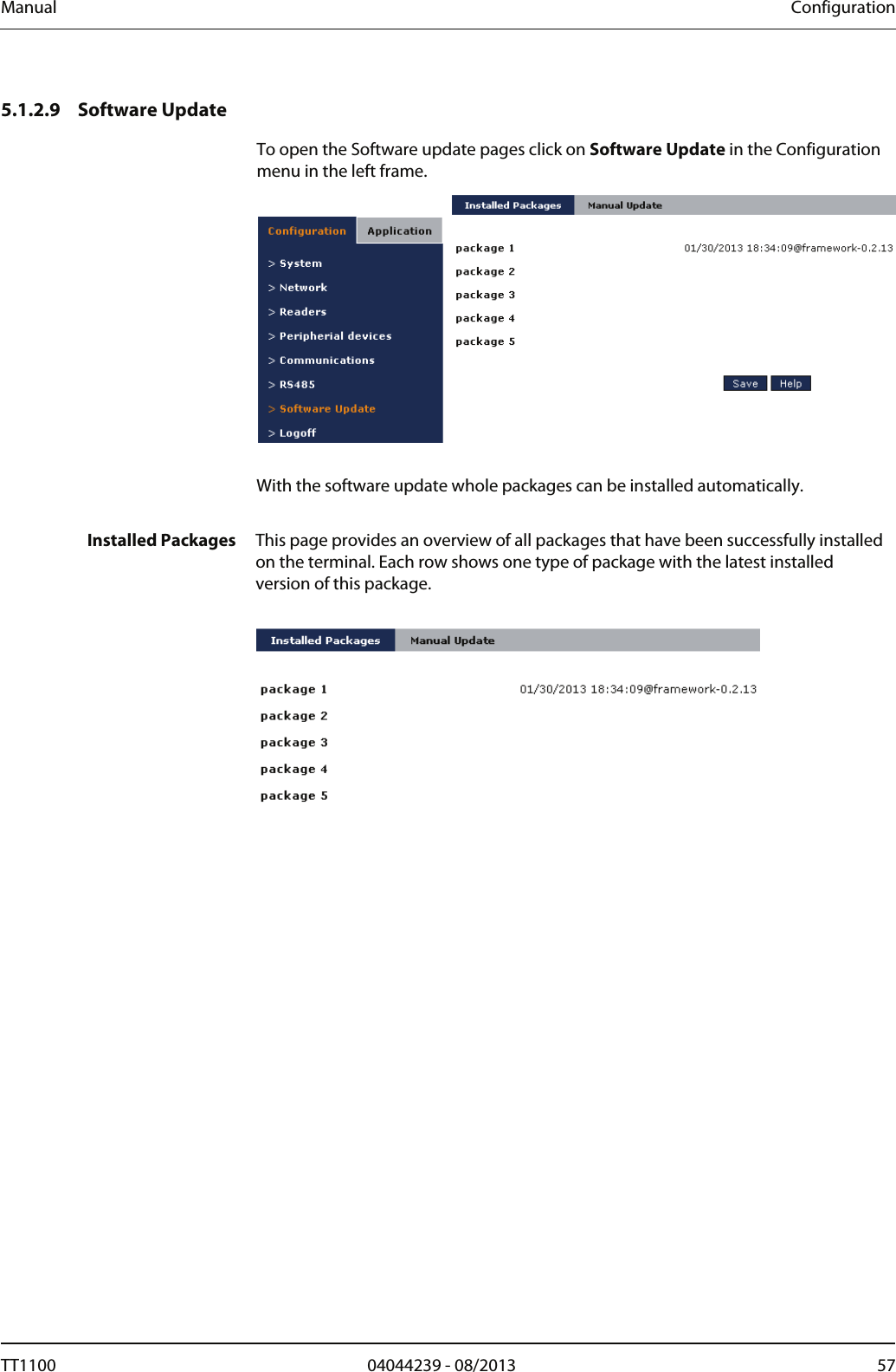
![Manual Configuration Message format Defines the format in which the messages are to be sent to the host. Default XML. Time-out for host reaction [ms] Time-out interval for a confirmation message from the host (ms). Default 10000. Server alive check The interval in seconds between the server alive checks, default 180. If during this interval no alive check exchange happens, the terminal is offline. Use time intervals for upload? Currently only for the connection type FTP. If this option is set to Yes, the connection to the FTP server will be established every n minutes, where n is the connection interval you specify in the next field. Default No. Upload connection interval The time interval in minutes you want the connection to the FTP server to be established. Choose an interval not less than 10. Use time slots for upload? By using online time slots you can restrict the permanent host connection to the specified periods of time. If you set this parameter to Yes you have to at least define one start-end-pair, during which the connection to the host is to be established. You can define up to 10 time slots. Default No. … Interval n Start [HH:MI] The time to go online in the format hh:mi. Interval n End [HH:MI] The time to go offline in the format hh:mi. If lower than the start time, the next day is assumed. Note that for the connection type FTP only the start time applies. TT1100 04044239 - 08/2013 49](https://usermanual.wiki/dormakaba-EAD/TT1100PRX/User-Guide-2055818-Page-49.png)
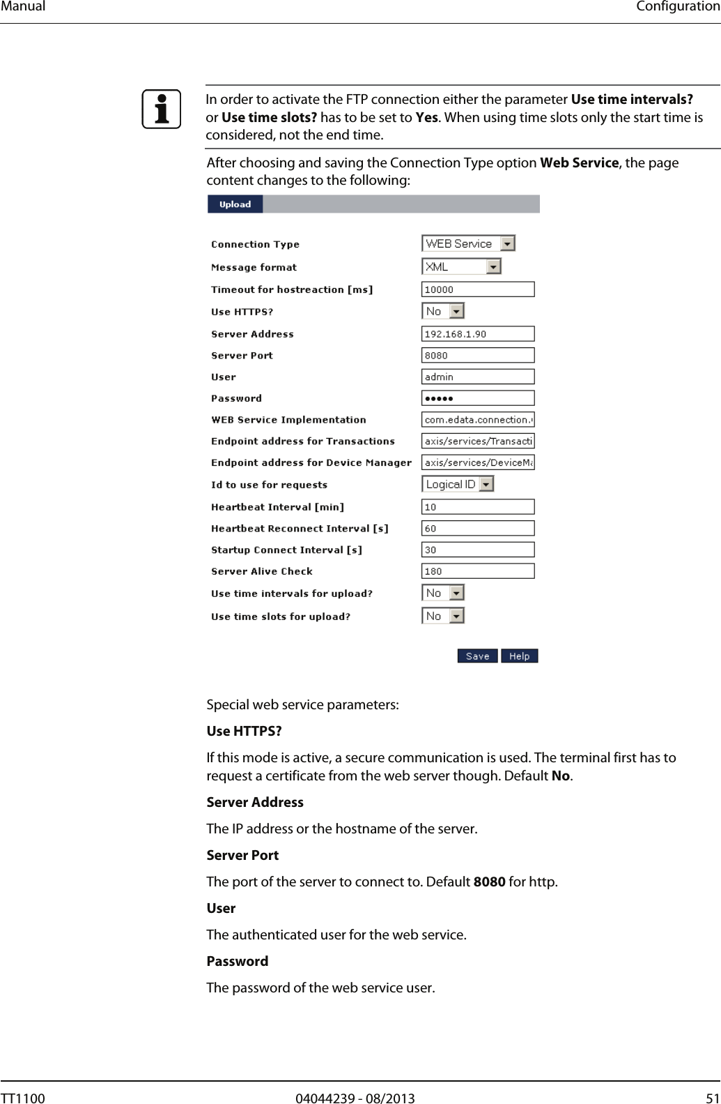
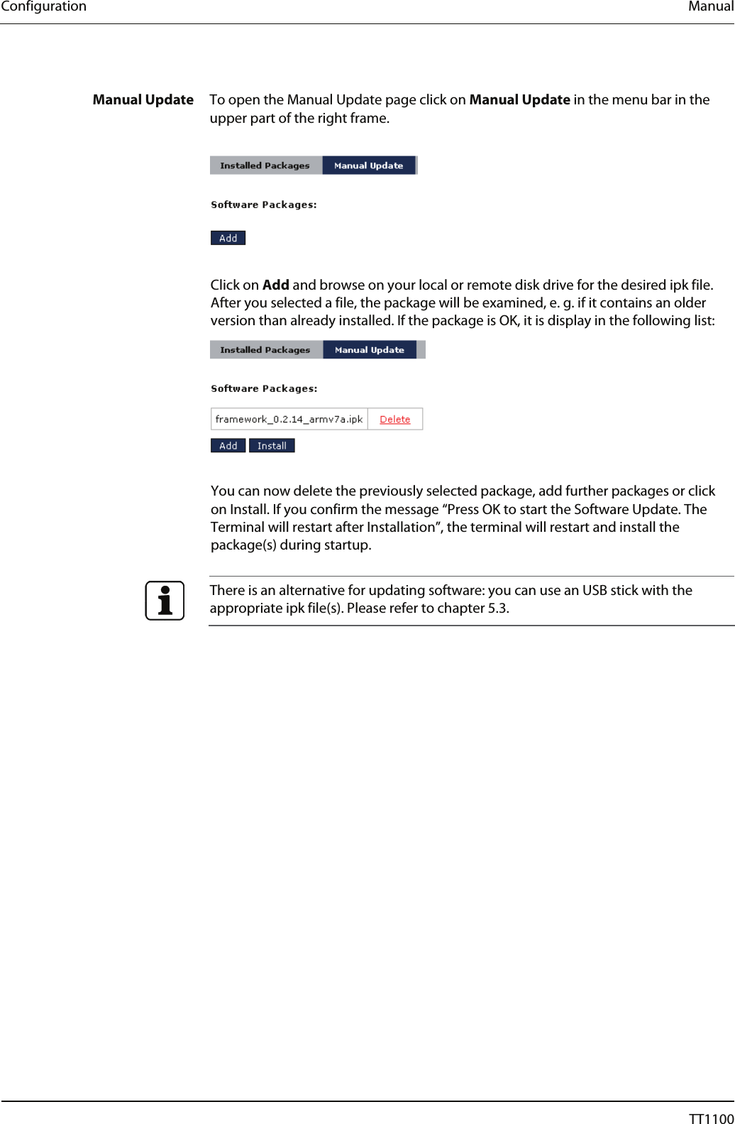
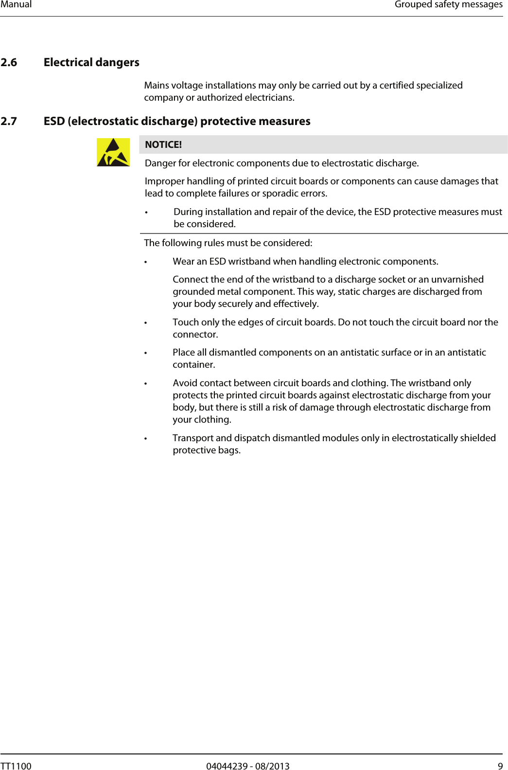
![Configuration Manual Web Service Implementation The class name of the web service implementation, default com.edata.connection.webservice.WSServerConnectionTL (For USA more often used: …WSServerConnectionTLUS) Endpoint address for Transactions The servlet (complete path) for receiving the transactions. Endpoint address for Device Manager The servlet (complete path) for processing other device messages such as the heart beat. Id to use for requests The ID used for server requests. This can be either the logical ID (the field Local terminal address on the terminal parameter page) or the name (the field Hostname on the network parameter page, by default the MAC address). Heartbeat Interval [min] The interval between heart beat messages in minutes, minimum 5 minutes, default 10 minutes. Heartbeat Reconnect Interval [s] For the offline case: the interval between reconnection tries in seconds, minimum 10 seconds, default 60 seconds. Startup Connect Interval [s] For the offline case at startup: the interval between reconnection tries in seconds, minimum 10 seconds, default 30 seconds. It is recommended to set the parameter Timeout for host reaction to 45 seconds (value 45000). Also it is recommended to set the parameter Server alive check to 0, because the alive check with Web service is done by heartbeats. 52 04044239 - 08/2013 TT1100](https://usermanual.wiki/dormakaba-EAD/TT1100PRX/User-Guide-2055818-Page-52.png)