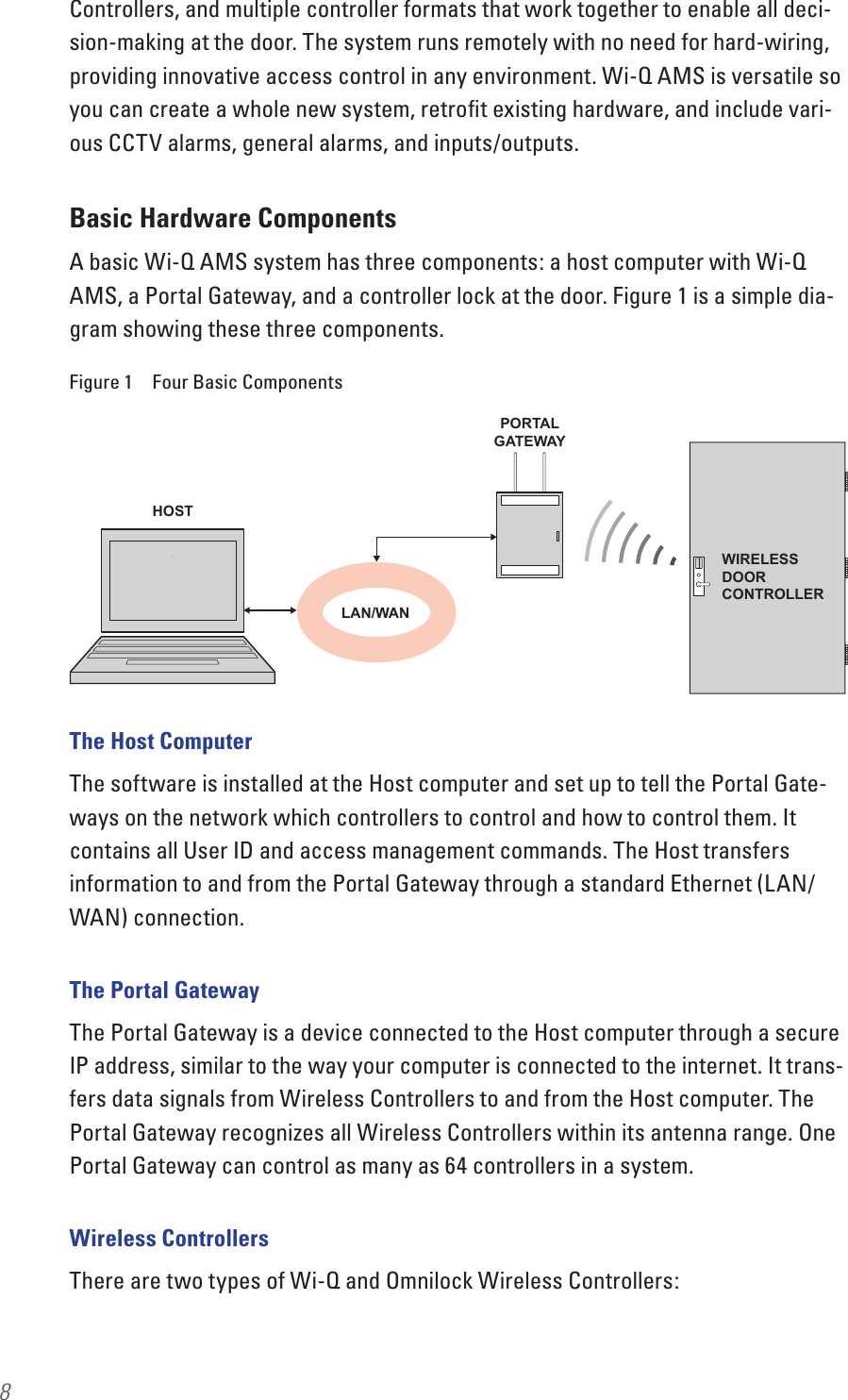
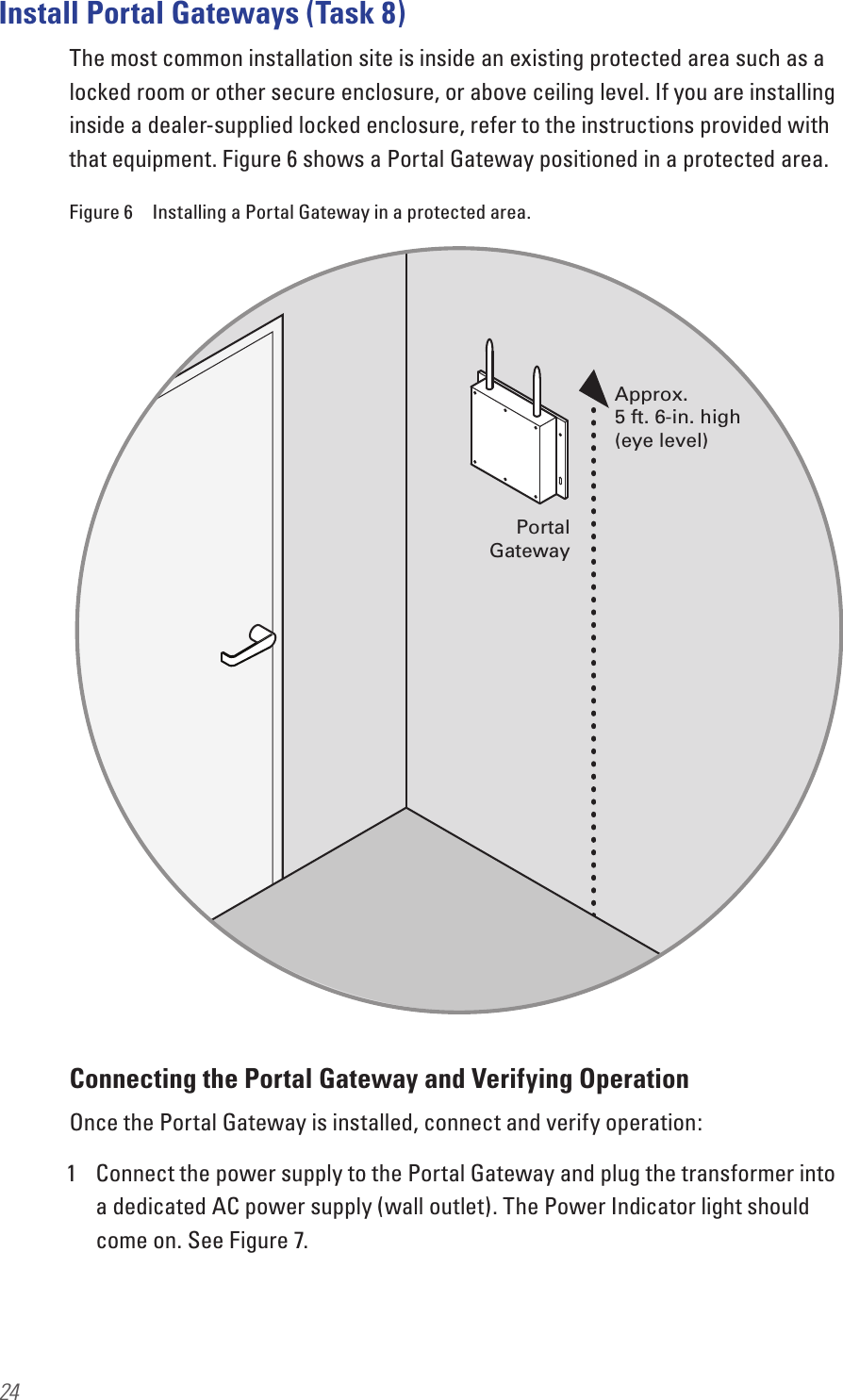
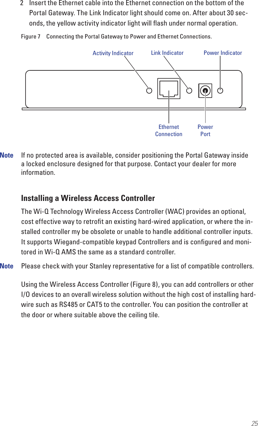
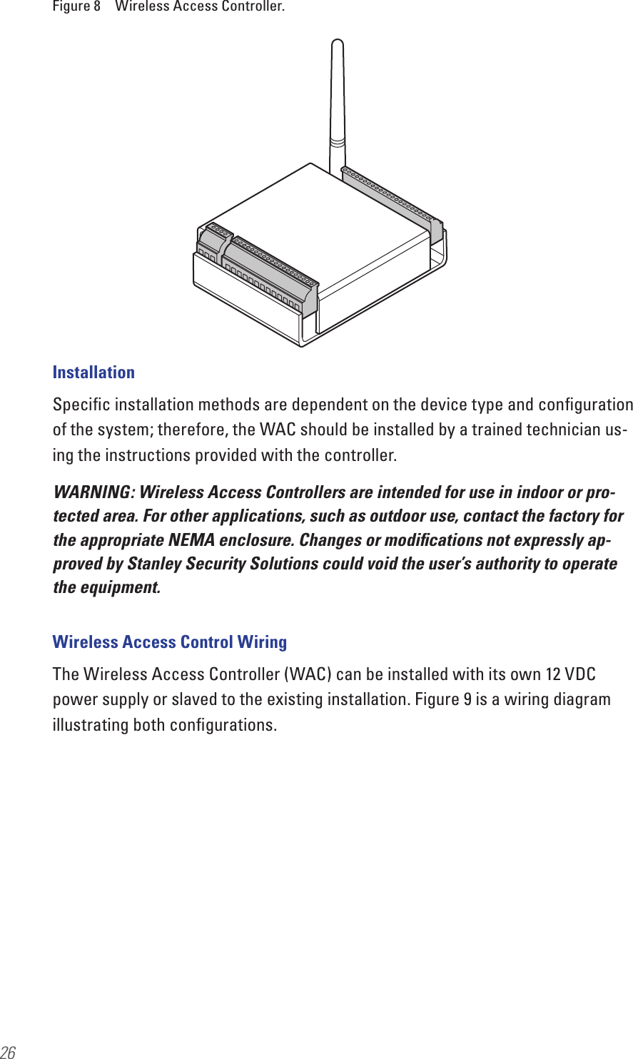
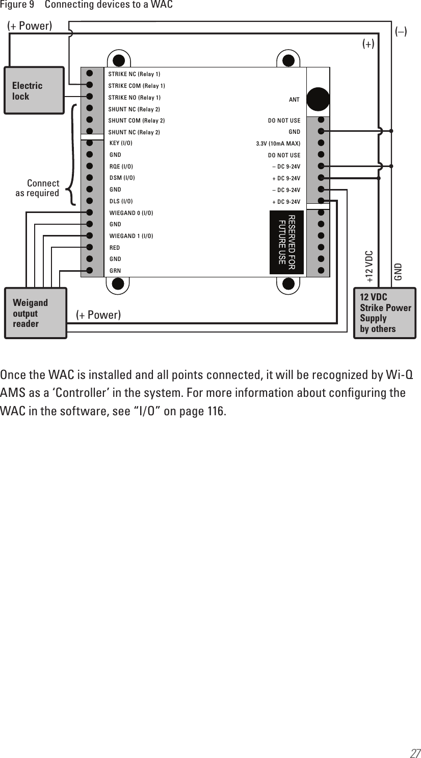
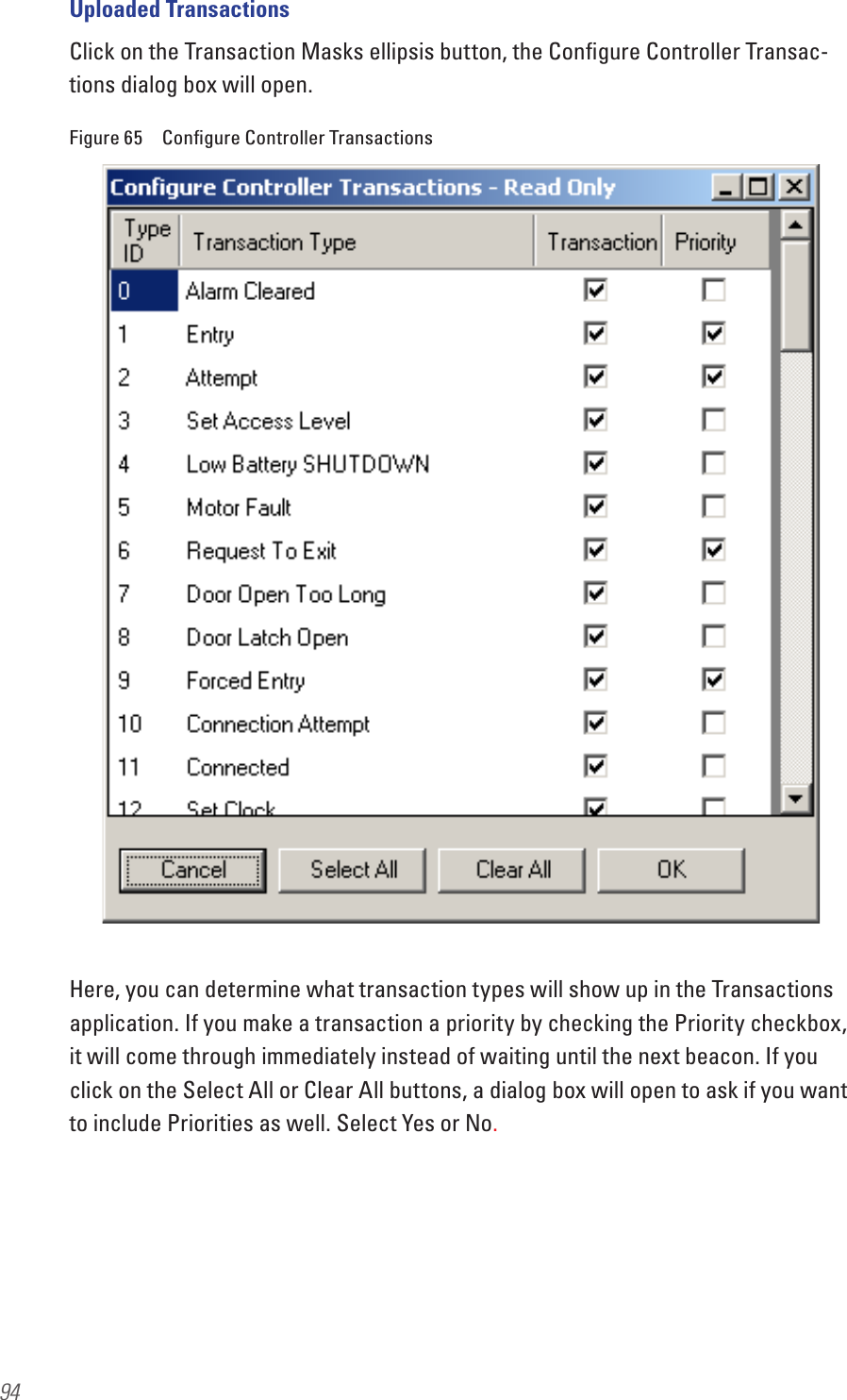
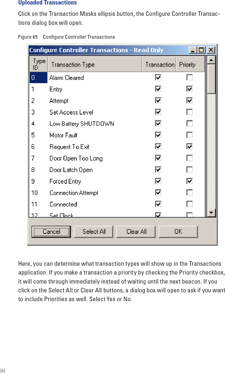
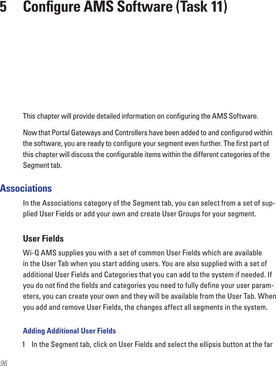
dormakaba USA C83068 Wireless Electronic Lock User Manual Users manual
Stanley Security Solutions, Inc. Wireless Electronic Lock Users manual
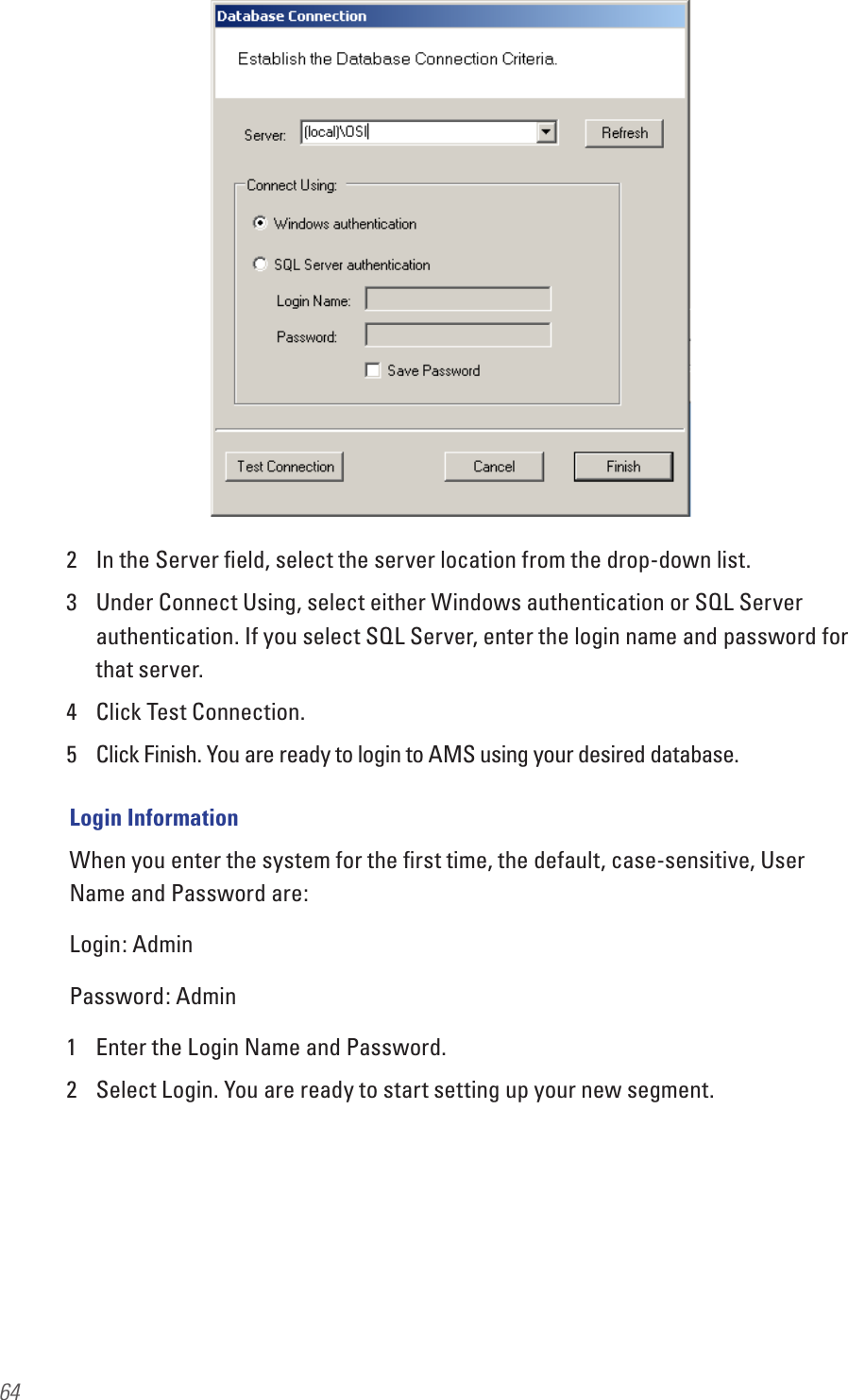
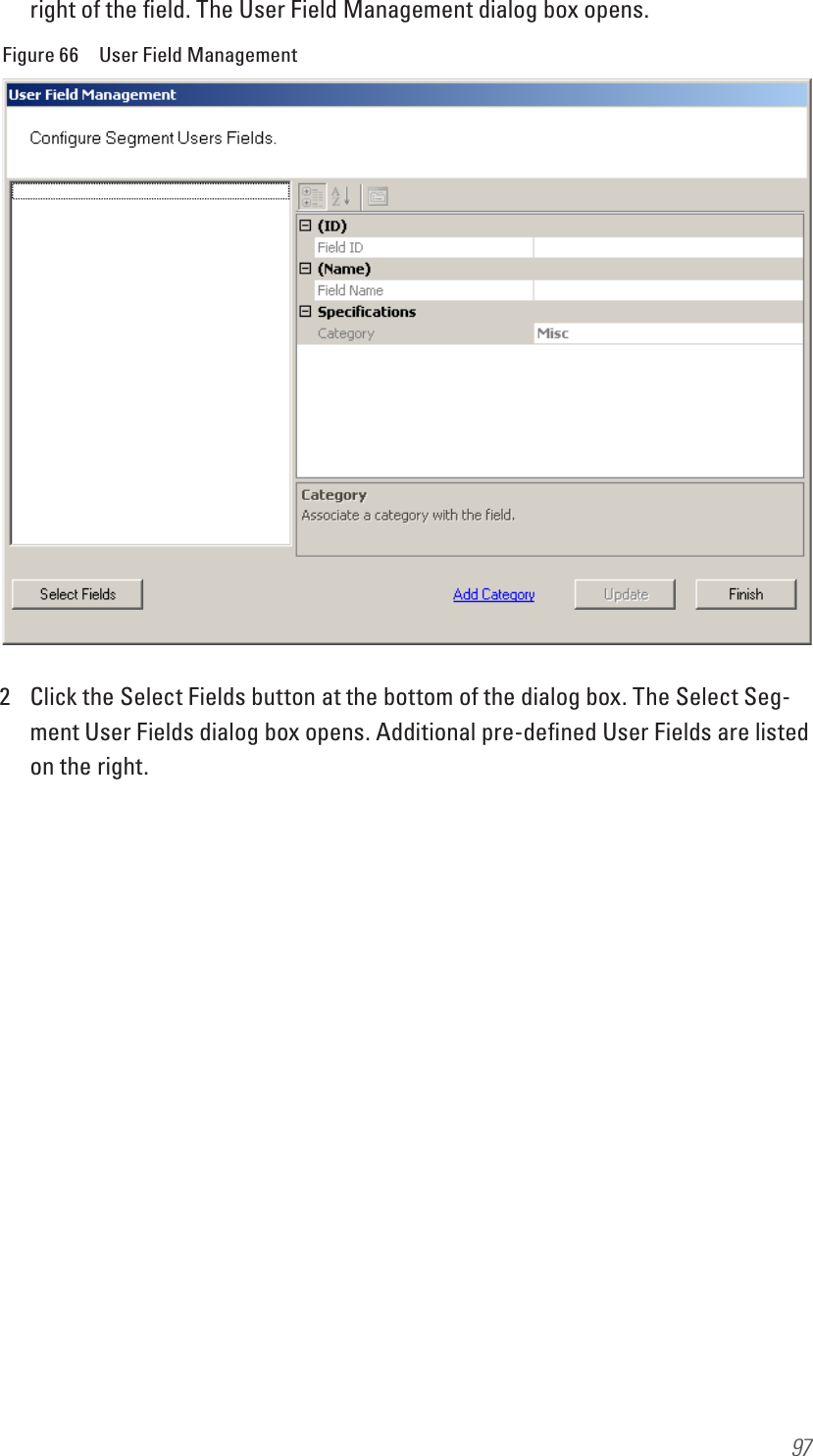
UserManual.wiki
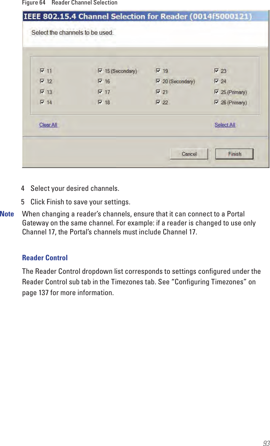
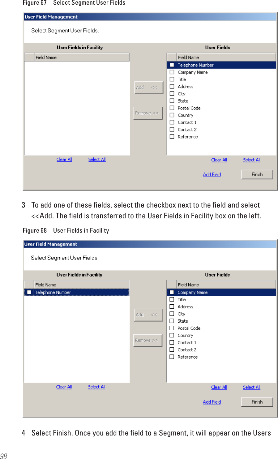
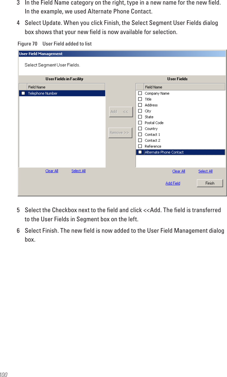
>
dormakaba USA
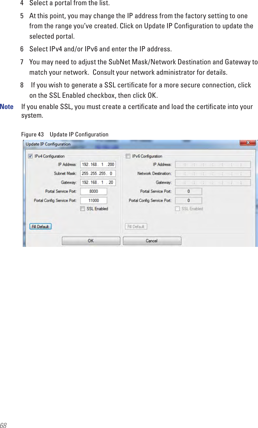
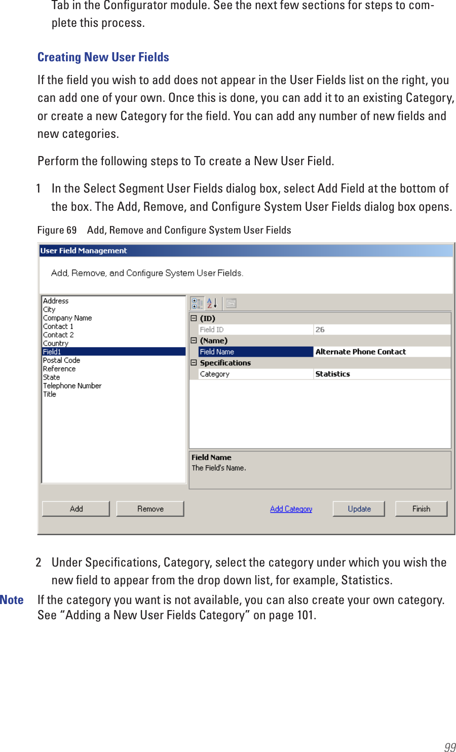
>
C83068 User Manual
Users manual
Navigation menu
Upload a User Manual
Namespaces
Wiki Guide
HTML
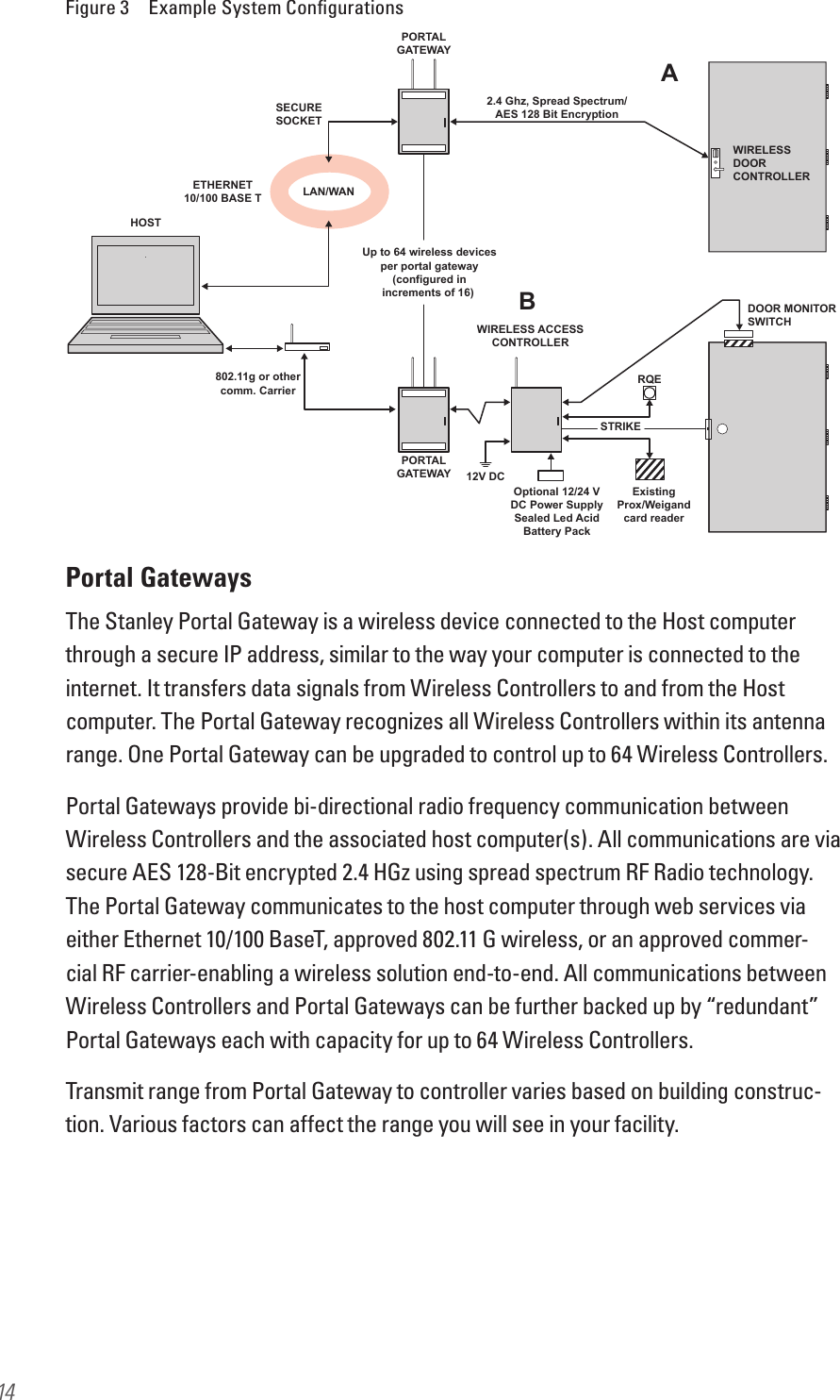
PDF
Info
Views
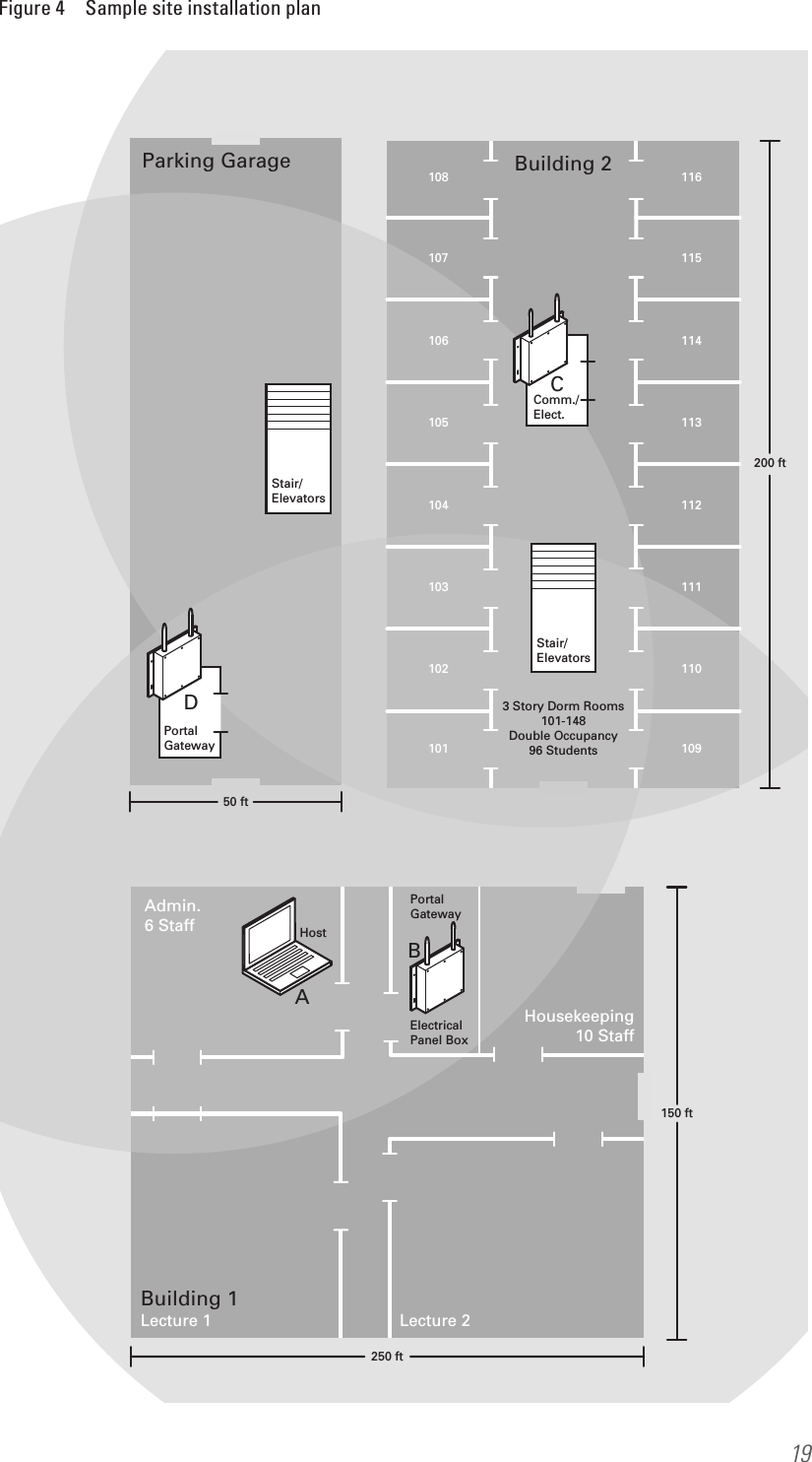
User Manual
Discussion / Help
Navigation
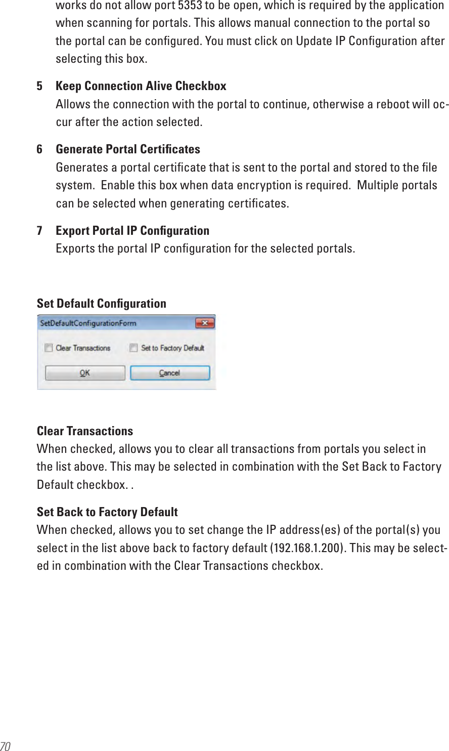
![FCC/IC CertificationCAUTION: Please keep the PG antenna 20cm away from people to ensure that FCC RF exposure compliance requirements are not exceeded.This equipment has been tested and found to comply with the limits for Class B Digital Device, pursuant to Part 15 of the FCC Rules. These limits are designed to provide reasonable protection against harmful interference in a residential installation. This equipment generates and can radiate radio frequency energy and, if not installed and used in accordance with the instructions, may cause harmful interference to radio communications. However, there is no guarantee that interference will not occur in a particular installation. If this equipment does cause harmful interference to radio or television reception, which can be determined by turning the equipment off and on, you can try to correct the interference by taking one or more of the following measures. Reorient or relocate the receiving antenna Increase the separation between the equipment and receiver Connect the equipment into an outlet on a circuit different from that to which the receiver is connected Consult the dealer or an experienced radio/TV technician for help.This device complies with Industry Canada licence-exempt RSS standard(s). Operation is subject to the following two conditions: (1) This device may not cause interference, and (2) this device must accept any interference, including any interference that may cause undesired operation of the device. Cet appareil est conforme à la norme RSS Industrie Canada exempt de licence. Son fonctionnement est soumis aux deux conditions suivantes: (1) cet appareil ne doit pas provoquer d’interférences et (2) cet appareil doit accepter toute interférence, y compris les interferences pouvant causer un mauvais fonctionnement du dispositif. This Class [B] digital apparatus meets all requirements of the Canadian Interference-Causing Equipment Regulations. Cet appareil numérique de la classe [B] respecte toutes les exigences du Réglement sur le matériel brouilleur du Canada.](https://usermanual.wiki/dormakaba-USA/C83068/User-Guide-2675620-Page-3.png)