dormakaba USA W2000 Wireless Access Management System Reader User Manual A12831A
Stanley Security Solutions, Inc. Wireless Access Management System Reader A12831A
manual
9-2
REMOVING OUTSIDE LEVER WITH INTERCHAN-
GEABLE (I.C.) CORE
a. Insert the control Key into the I.C. Core and rotate it
15° clockwise. Pull on the Key to remove the I.C.
Core. Be sure that the I.C. Tailpiece is removed with
the Core.
b. Ensure that the Retaining
Ring and the Anti-Pick Plate
are aligned with the Lever
Catch as shown.
c. Insert an awl or a small
screwdriver through the I.C.
Outside Lever and into the slot in
the Anti-Pick Plate. Depress the
Lever Catch toward the Door
Hinge and slide the I.C. Outside
Lever from the Spindle.
SECURITY
D E V I C E S
OMNILOCK
TWISTED
PAIR
SWITCH
SECTION 6: INSTALL THE STRIKE
a. Mark the location of the Latch Bolt on the Door Frame.
b. Center the Strike over the Latch Bolt Mark and, using the Strike as a template, mark
the Frame.
c. Using the Strike Box as a template, mark the Frame.
d. Mortise the Frame to accept the Strike and Strike Box.
e. Install the Strike Box and the Strike and secure with the Screws.
SECTION 7: PROGRAM THE LOCKSET
IMPORTANT:
To avoid unauthorized access, it is important to program a new Programmer
ID
.
Refer to the OMNILOCK Administrator’s Guide for programming instructions. If the System has been installed on a door before the
required programming information is available, and your system has a keypad, the access Level may be set to Unlocked as follows:
a. Enter the Default Manager ID 2222, at the keypad, the green light will flash.
b. Press 2, the green light will flash.
c. Press and hold the CL key until the green light flashes four times. (The light will flash once when the CL key is pressed,
continue to hold the key until the light flashes three more times.)
d. The System will remain in the Unlocked mode.
SECTION 8: INTERCHANGEABLE CORE
8-1
INTERCHANGEABLE (I.C.) CORE AND TAILPIECE
INSTRUCTIONS FOR ARROW I.C. CORES
Be certain to use the correct Tailpiece with the Core. Six-Pin
Cores use only the “L6” Tailpiece and Seven-Pin Cores use
only the “L7” Tailpiece.
SECTION 9: REMOVAL OF LEVERS
9-1
REMOVING OUTSIDE LEVER WITH STANDARD CYLINDER
a. Insert the Key into the Cylinder and turn 45°
clockwise.
b. Depress the Lever Catch through the
hole in the Outside Lever by using the
Push Pin provided or another suitable
tool.
c. Slide the Outside Lever from the Spindle.
9-3 REMOVING THE INSIDE LEVER
a. Depress the Lever Catch through the
hole in the Inside Lever by using the
Push Pin provided or another suitable
tool.
b. Slide the Inside Lever from the
Spindle.
SECTION 10: REMOTE SWITCH
a. Remote operation of the System may be accomplished by a momentary Switch closure. This
may be desirable for someone monitoring a protected entrance, such as a receptionist.
Momentarily pressing the Switch will cause the System to go through a normal unlock and
lock sequence. If the Switch is held closed, the open time will be extended.
b. Connect a twisted pair of wires from the Terminal Block on the PC Board to a normally open
momentary contact Switch. Plan the route for your wire and the access route through the
door to the PC Board in the OMNILOCK Module. Plan for disconnecting the wires in the Lock
area so that the System can be removed from the door to change the Batteries as required.
1580 JAYKEN WAY
CHULA VISTA, CALIFORNIA 91911
(619) 628-1000 FAX (619) 628-1001
(Website: WWW.OMNILOCK.COM)
PAGE 4 OF 4
STRIKE
BOX
STRIKE
SCREW
#12 X 3/4"
(2 REQ’D)
Copyright 2003 OSI Security Devices Inc. All Rights Reserved.
OMNILOCK is a Registered Trademark of OSI Security Devices Inc. Arrow is a Trademark of Arrow Lock Co. 12831 Rev.A
NOTE:
There are two styles of Tailpieces, one
style has equal length pins and the
other style has unequal length pins.
Use the Tailpiece with equal length
pins if the pins will completely enter the
holes in the Core. Otherwise use the
Tailpiece with unequal length pins and
install the O-ring onto the Tailpiece tab.
8-2
INTERCHANGEABLE (I.C.) CORE INSTALLATION
Insert the applicable I.C. Tailpiece into the I.C. Core. Insert
the Control Key into the I.C. Core and turn it 15°
clockwise. Insert the Core into the I.C. Outside Lever and
turn the Control K
ey 15° counterclockwise to lock the Core
in the Lever. Remove the Control Key.
I.C. TAILPIECE
I.C. CORE
CONTROL
KEY
I.C OUT
SIDE
LEVER
KEY
OUTSIDE
LEVER
PUSH PIN
(PROVIDED)
INTSIDE
LEVER
PUSH PIN
(PROVIDED)
I.C.
CORE
TAILPIECE
(UNEQUAL LENGTH PINS)
TAILPIECE
(EQUAL
LENGTH PINS)
O-RING
OUTSIDE SPINDLE
END VI
EW
ANTI-PICK
PLATE
LEVER
CATCH
OUTSIDE
SPINDLE
RETAINING
RING
+
-
+
-
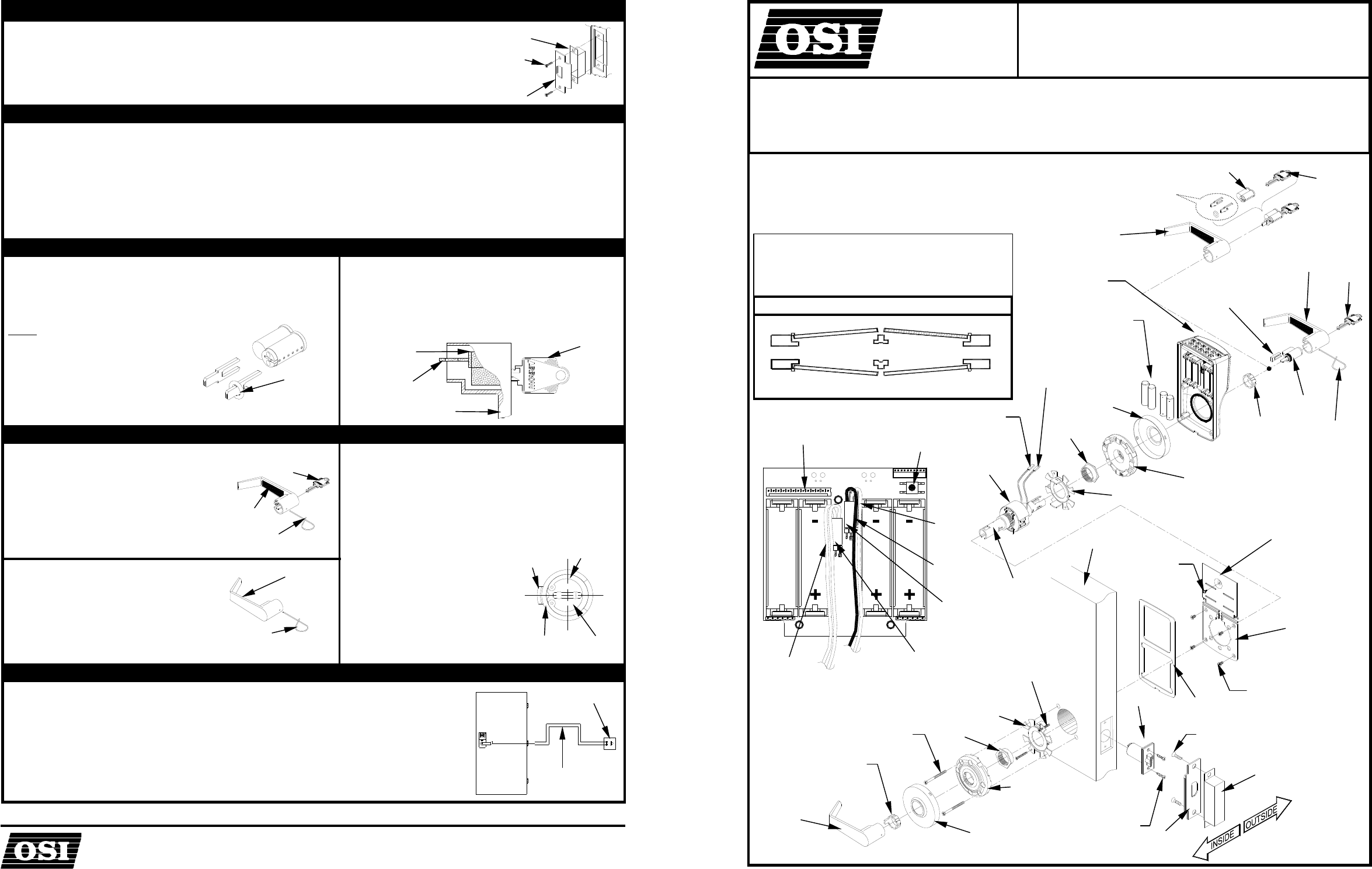
PAGE 1 OF 4
BATTERY
COVER
BACK
PLATE
GASKET
HOUSING
ASSEMBLY
OUTSIDE
LEVER
I.C.CORE
AA
ALKALINE
BATTERY, 1.5V, 3VOLT
(4 REQ’D)
LOCK
BODY
USE APPLICABLE
TAILPIECE
SEMS,
PAN HEAD,
#4-
40 X 1/4LG
SCREW, FLAT HEAD,
#8-32 X 3/8” LG
(4 REQ’D)
NUT
SCREW, FLAT HEAD,
#8 X 3/4” LG
(2 REQ’D)
SCREW, FLAT HEAD,
#10-32 X 2-1/4”LG
(2 REQ’D)
SCREW, PAN HEAD,
#6 X 3/4”LG
(2 REQ’D)
SCREW, FLAT HEAD,
#12 X 3/4” LG
(2 REQ’D)
CONTROL
KEY
ROSE
OUTSIDE ROSE
INSERT ASSEMBLY
MOTOR
CONNECTOR
FLEXIBLE
ADAPTER
PLATE
DOOR
SPINDLE
LATCH
UNIT
STRIKE BOX
STRIKE
NUT
ROSE
OUTSIDE ROSE
INSERT ASSEMBLY
FLEXIBLE
ADAPTER
PLATE
INSIDE
LEVER
WARNING:
THIS PRODUCT IS
NOT WARRANTED
FOR OUTDOOR USE!
WARNING: CHANGES OR MODIFICATIONS NOT EXPRESSLY
APPROVED BY OSI SECURITY DEVICES COULD VOID THE
USER’S AUTHORITY TO OPERATE THE EQUIPMENT.
NOTE: A DOOR-CLOSER IS HIGHLY RECOMMENDED FOR
USE WITH THIS PRODUCT.
THIS PRODUCT IS NORMALLY FACTORY-PACKED
FOR RIGHT-HAND 1-3/4” THICK DOORS.
TO CHANGE HAND OF LOCK SEE
INSTRUCTION SECTION 3
DO NOT USE ON DOORS THICKER THAN 1-3/4”.
KEY DETECTION
CONNECTOR
(OPTION 1)
I.C. OUTSIDE
LEVER
CYLINDER
KEY
RETAINER
PUSH PIN
(PROVIDED)
RESET BUTTON
MOTOR
CONNECTOR
RED
WIRE
BLACK
WIRE
2 YELLOW
WIRES NO
POLARITY
(OPTION 1 ONLY)
KEY
DETECTION
CONNECTOR
CONNECTOR
SECURITY
DEVICES OMNILOCK
®
ACCESS CONTROL SYSTEMS
INSTALLATION INSTRUCTIONS FOR OPW2000 SERIES
NON-WEATHERIZED, CYLINDRICAL LOCKSET USING
ARROW™
Q-SERIES LOCK (LEVER)
READ COMPLETE INSTRUCTION BEFORE PROCEEDING.
RIGHT HAND SHOWN
RIGHT HAND
REVERSE
BEVEL
LEFT HAND
REVERSE
BEVEL
LEFT
HAND
RIGHT
HAND
OUTSIDE
INSIDE
OUTSIDE
DOOR HANDLING
DOOR HANDS DETERMINED FROM OUTSIDE
+
-
LEFT HAND
ORIENTATION
SHOWN
RESET
BUTTON
MOTOR
CONNECTOR
RED
WIRE
BLACK
WIRE
KEY DETECTION
CONNECTOR
2 YELLOW WIRES
NO POLARITY
CPU PC
BOARD ASSY
SEMS
#4-40 X .25
PAN HEAD
GASKET
BATTERY
COVER
HOUSING
ASSEMBLY
LOCKSET
ASSEMBLY
SCREW
PAN HEAD
#8-32 X .375
(4 REQ’D)
CONNECTOR
SECTION 1: INSTALL THE KEY CYLINDER AND OUTSIDE LEVER
1-1 If the Lever requires a standard Key cylinder, proceed as follows:
a. Using standard Pliers, pull out the Outside Retainer.
b. Insert the Cylinder into the Outside Lever.
c. Secure the Cylinder by pressing the retainer until it is flush with the shelf.
d. Slide the Outside Lever onto the Outside Spindle as far as possible. Insert the
Key and turn ot 45° clockwise. Push the Lever again , until the Lever Catch is
engaged, securing the Lever.
1-2 If the Lever requires an Interchangeable core (I.C.), proceed as follows:
a. Ensure that the retaining Ring and Anti-pick Plate are oriented as shown.
b. Push the I.C. Lever onto the Outside Spindle until the Lever Catch is engaged.
c. Install the Interchangeable Core per Section 8.
SECTION 2: CHECK OPERATION
a. Verify proper operation of the System using the Default Programmer ID Proximity card. Momentarily place the center of the
Proximity Card (Included in the OMNILOCK Administrator’s Kit) over the recess in the front of the OP2000. The OP2000
will flash green once and unlock, then, during the Open Delay Time, it will flash green five times. The OP2000 will flash
red and lock. While unlocked, check for proper operation of the lock.
b. If your System has a Keypad Proceed as follows, otherwise go to Step c: Verify proper operation of the System using the
Keypad. Enter the Default Programmer ID, 1 2 3 4 , at the Keypad. The Lights will flash as in the previous step.
c. If Key Detection is installed, proceed as follows, otherwise go to step d: Verify proper operation of the Key Detection
Indicator by inserting the Key into the Key Cylinder and rotating clockwise. The green light will flash.
d. If the System malfunctions remove the Battery Cover and check for proper orientation and seating of the Batteries, Motor
Connector and Key Detection Connector. Ensure that the wires are not pinched.
Reset the electronics by pressing and
holding the Reset Button on the circuit board until the light flashes green, approximately three seconds. The System will go
through a self-test and flash green 5 times. Any red flash indicates an electronics or motor problem. Repeat the verification
process if all flashes are green.
SECTION 3: ADJUST THE LOCK HAND
3-1
This section is only required if the lock hand does not meet your requirements. The Lockset is normally preset for a right
hand door. Verify the handing of the Lock and, if required, change the hand of the Lock as follows after checking per
Section 2.
a. Carefully release the Gasket from the edge of the Housing Assembly
using your fingers, and remove the Gasket. Remove the Screw from
the Battery Cover and remove the Cover. Disconnect the Motor
Connector and Key Detection connector, if Key Detection is installed,
from the CPU Board.
b. Remove four Flat Head Screws from the Back Plate and remove the
Back Plate.
3-2
a. Rotate the lockset to left-hand orientation.
b. Route the Wires close to the center of the Lockset and to the upper
center of the Outside Rose.
c. Align Wires into the notch of the Back Plate under the Translucent Label.
Install the Back Plate and four Screws into the Housing Assembly.
WARNING: Ensure that the Wires are not pinched
before and after tightening the Screws.
d. Install the Motor Connector with the Black Wire to
the left (see label on CPU Board). Install the Key
Detection Connector (if available). Arrange the
excess wire between the Battery Holders.
e. Install the Battery Cover and secure it with the
Screw.
f. Install the Gasket so that it seats inside the edge
of the Housing.
OUTSIDE
LEVER
RETAINER
CYLINDER
SHELF
LEVER
CATCH
ANTI
-PICK
PLATE
RETAINING
RING
OUTSIDE
SPINDLE
OUTSIDE SPINDLE
END VIEW
PAGE 2 OF 4
SEM
#4-40 X .25
PAN HEAD
GASKET
BATTERY
COVER
HOUSING
ASSEMBLY
LOCKSET
ASSEMBLY
BACK PLATE
+
-
+
-
-
+
+
-
DOOR
DOOR
LOW
BEVEL
DOOR STOP
TEMPLATEATE
HIGH
BEVEL
5-3
Install the Plate and Nut on the inside,
and secure the Plate with the Screws.
LOCK BODY
RETRACTOR
LATCH UNIT
PRONGS
LATCH UNIT
TIALPIECE
LOCK
BODY
SHORT MARK
LOCATED ON
PLATE
LOCK BODY
NUT
SCREW PAN
HEAD #6 X 3/4"
(2 REQ’D)
NUT
PLATE
SECTION 4: PREPARE THE DOOR
4-1 MARK HOLE LOCATIONS
a. Mark a height line on the door faces and edge (suggested height
is 38" from the floor).
b. Line up the Template at the correct marking for the Door Bevel
(high or low bevel, or flat). Position the centerline of the Template
on the height line. Note whether the holes should be marked on
the inside, outside, or both sides of the door. Mark the centers as
required for the holes.
c. Mark the center of the Door thickness on the height line.
4-2 DRILL HOLES
a. Bore the 2-1/8" hole and the 7/16" holes half way through the door from both sides to
avoid splintering.
b. Add the notches to both sides of the door.
c. Bore a 1" hole into the door edge center on the height line. Use the Latch Unit
Faceplate as a pattern and mark the door edge. Mortise the door edge so that the front
of the faceplate will be flush with the door edge. Insert the Latch Unit into the 1" hole,
making certain that the Latch Bolt Bevel faces the direction of the closing Door.
d. Secure the Latch Unit with the Screws supplied.
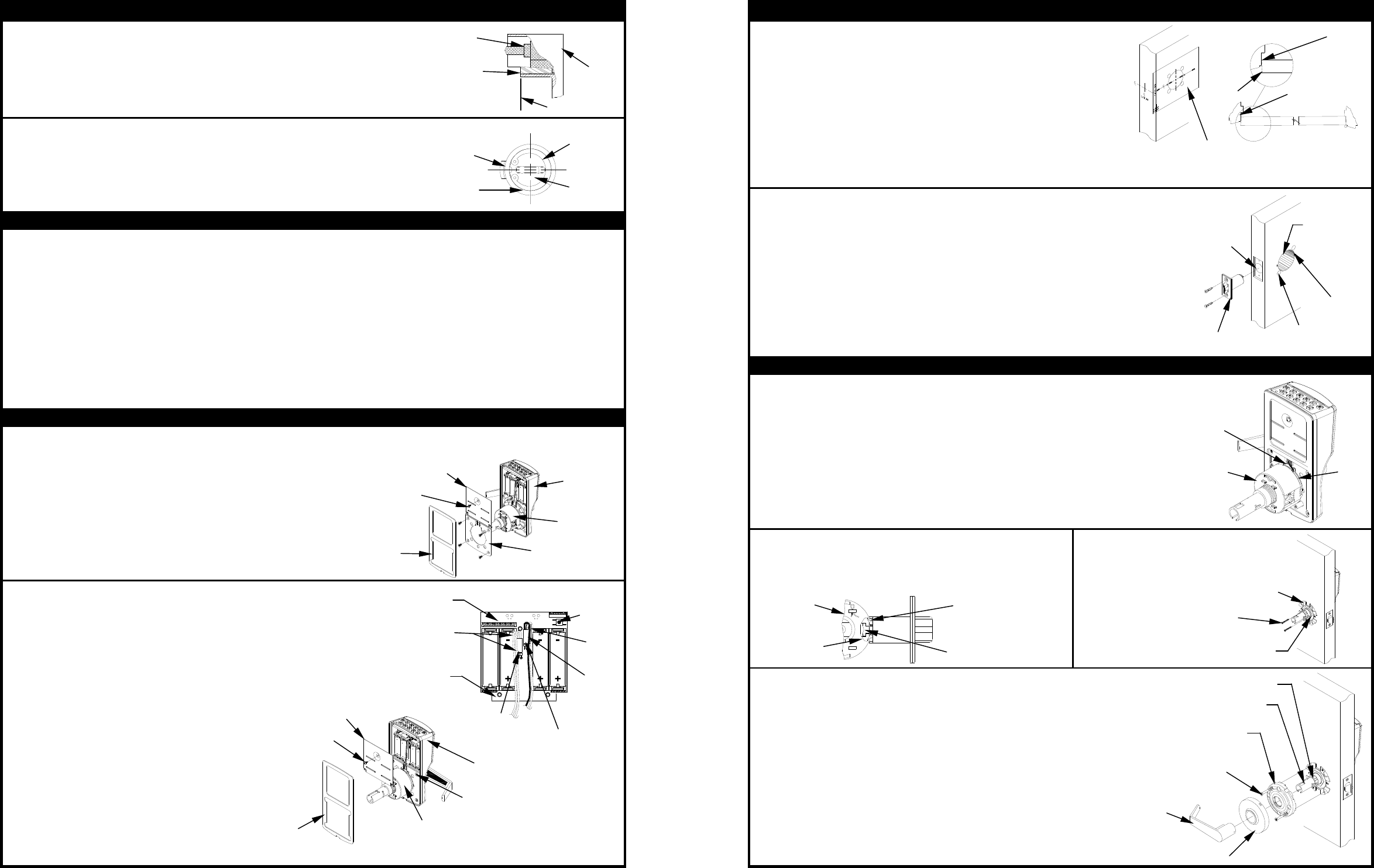
SECTION 5: INSTALL THE SYSTEM ON THE DOOR
5-1
NOTE: DO NOT USE ON A DOOR THICKER THAN 1-3/4" UNLESS
THE SYSTEM IS SPECIFICALLY DESIGNED FOR A THICKER
DOOR
a. The Lockset is preset for a 1-3/4" Door. For 1-3/4" Door the "short mark” on
the Lockset Plate is aligned with the edge on the Lock Body.
b. For a 1-3/4" door with a Push Plate (.050" max.) turn the Nut counter clock-
wise until the short mark is the thickness of the Push Plate from the edge of
the Lock Body. Adjust the Outside Nut with a pair of narrow jaw Pliers, a
small Screwdriver, a Scribe, or your Fingers.
c. If a Remote Switch is to be used to operate the System, see Section 10.
5-2
Install the System on the outside of the door. The Lock Body
must engage the Latch Unit Prongs as shown. The Lock Body
Retractor must engage the Latch Unit Tailpiece.
5-4
a. Align the Tab of the Flexible Adapter opposite to the Lever Catch.
b. Slide the Rose Insert onto the Inside Spindle so that the projections of the
Flexible Adapter line up with matching depressions of the Rose Insert
Assembly and secure the Rose Insert with the Screws.
c. Place the Inside Rose onto the Rose Insert aligning the dimples with the
recesses in the Rose Insert and turn clockwise to secure it. Slide the Inside
Lever on the Inside Spindle. Make certain that the Lever Catch on the
Spindle is engaged with the Lever.
d. Repeat Section 2 to verify proper operation.
PAGE 3 OF 4
Binding or rough operation is an indication of improper installation.
2-1/8” HOLE
1” HOLE
LATCH UNIT
NOTCH
(4 REQ’D)
7/16” HOLE
(REQ’D)
SCREW,
FLAT HEAD
#10-24 X 2-
1/4”
(2 REQ’D)
FLEXIBLE ADAPTER
INSIDE
LEVER
INSIDE ROSE
ROSE
INSERT
INSIDE
SPINDLE