dresden elektronik ingenieurtechnik MEGA22A02 2.4GHz 802.15.4/ZigBee/6LoWPAN/RF4CE radio module User Manual
dresden elektronik ingenieurtechnik gmbh 2.4GHz 802.15.4/ZigBee/6LoWPAN/RF4CE radio module
UserManual.wiki
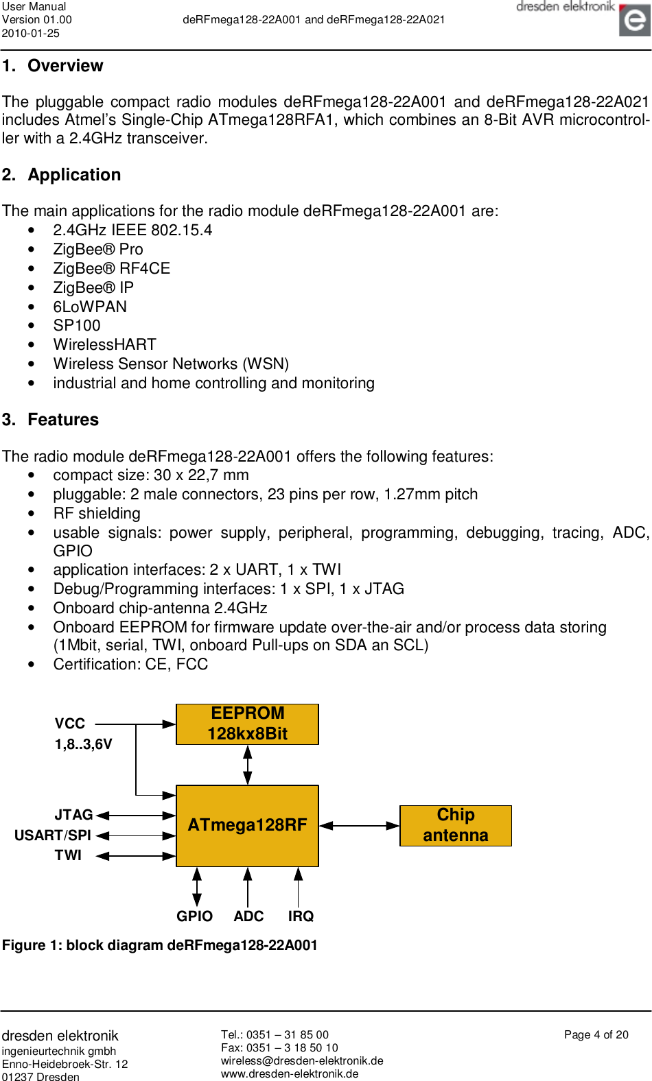
>
dresden elektronik ingenieurtechnik
>
MEGA22A02 User Manual
Users Manual
Navigation menu
Upload a User Manual
Namespaces
Wiki Guide
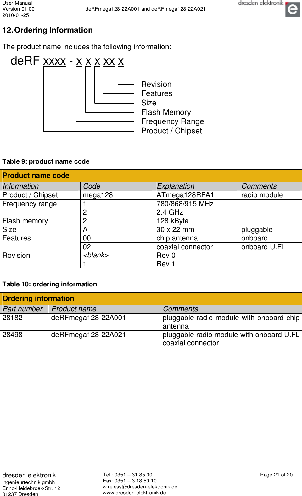
HTML
PDF
Info
Views
User Manual
Discussion / Help
Navigation
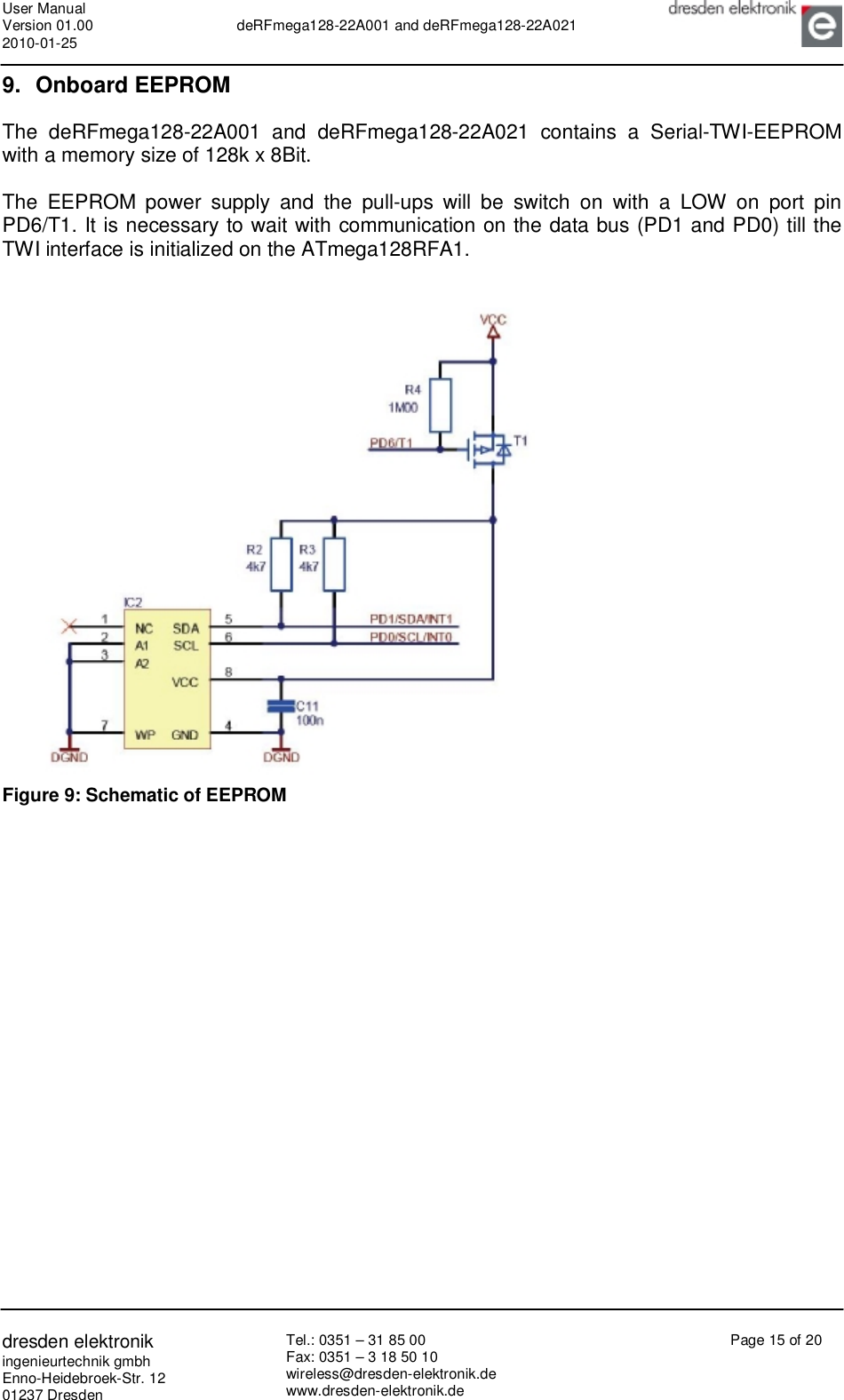
![User Manual Version 01.00 2010-01-25 deRFmega128-22A001 and deRFmega128-22A021 dresden elektronik ingenieurtechnik gmbh Enno-Heidebroek-Str. 12 01237 Dresden Tel.: 0351 – 31 85 00 Fax: 0351 – 3 18 50 10 wireless@dresden-elektronik.de www.dresden-elektronik.de Page 20 of 20 11.3. Approved antennas The deRFmega128-22A001 has an integrated chip antenna. The design is fully compliant with all regulations. The deRFmega128-22A021 has been tested and approved for use with the antenna listed below. The module may be integrated with other custom design antennas which OEM in-staller must authorize with respective regulatory agencies. The used antenna was connected to the radio module with a 10cm “U.FL-to-SMA-Reverse pigtail”. Table 8: Approved antenna(s) and accessory Approved antenna(s) and accessory Part number Description Manufacturer Gain [dBi] Min. Separation [cm] 23768 Dual-band antenna (2.45GHz and 5.8GHz) with Reverse-SMA-Connector, ¼ wave Antenna Factor +4,7 20 23769 U.FL-to-SMA-Reverse pigtail, 10 cm Hirose / Profineon -0,37](https://usermanual.wiki/dresden-elektronik-ingenieurtechnik/MEGA22A02/User-Guide-1283428-Page-20.png)