e DATA TLR401 Fingerprint keypad User Manual TLR401 Manual
e-DATA GmbH Fingerprint keypad TLR401 Manual
e DATA >
Contents
- 1. Users manual
- 2. Information about modifications
Users manual

TLR401 FP Administration and Enrollment
1
TLR401 FINGERPRINT KEY
Manual Version 1.2
TIMELINK International GmbH

TLR401 FP Administration and Enrollment
2
TIMELINK International GmbH
Mollenbachstrasse 19
D-71229 Leonberg
Telefon (0 71 52) 93979-0
Telefax (0 71 52) 93979-50
info@titze.de
TLR401 FP Enrollment Manual
Version 1.2
Copyright 2008 TIMELINK International GmbH
This Manual is protected by copyright. The user manual may only be
copied within the framework of the intended usage. Any reproduction
or translations of the manual beyond this or its transmission onto
electronic media, even in extract form, is only allowed with the express
permission of TimeLink International.
TimeLink International reserves the right to make changes to the user
manual and to the devices without special notice.
TimeLink International does not accept any liability whatsoever for
direct or indirect damage, especially loss of data, that results from the
usage of the TLR401 terminal, or from the information in this Manual

TLR401 FP Administration and Enrollment
3
Content
1General Comments 6
1.1 Symbols....................................................................................6
1.2 Device name.............................................................................7
1.3 Intended Usage ........................................................................7
1.4 Protection Class........................................................................7
1.5 Safety Measures.......................................................................7
1.6 Before Commissioning..............................................................7
1.7 Operation..................................................................................7
1.8 Installation and Service.............................................................8
1.9 CE Conformance ......................................................................8
2Technical Data 9
2.1 Mechanical Structure ................................................................9
2.2 Hardware Features ...................................................................9
2.3 Biometric Sensor.......................................................................9
2.4 Display......................................................................................9
2.5 Connection................................................................................9
2.6 Interface....................................................................................9
2.7 Power Supply..........................................................................10
2.8 Environment Conditions..........................................................10
2.9 Dimensions and Weight ..........................................................10
2.10 Cable Specifications ...............................................................10
3Installation 11
3.1 Installation Requirements........................................................11
3.2 Condition ................................................................................11
3.3 Wiring .....................................................................................11
4Configuration Settings 12
4.1 Before Power ON....................................................................12
5Wiring and Jumpers 12
6General Introduction 13

TLR401 FP Administration and Enrollment
4
6.1 View of the control elements...................................................13
6.2 Basics.....................................................................................14
6.3 Basic operating principles .......................................................14
6.4 Operating modes ....................................................................15
6.4.1 User Operation (without iCLASS):...........................................16
6.4.2 User Operation with iCLASS:..................................................16
7Administrator Functions 17
7.1 Enrollment...............................................................................17
7.2 Delete Single User..................................................................18
7.3 Delete Database.....................................................................19
7.4 Change to Operation Mode Identify (Default)..........................19
7.5 Change to Operation Mode Verify...........................................20
7.6 Change to Operation Mode User ID from iCLASS Card..........20
7.6.1 Operation Mode User ID from iCLASS Card ...........................20
7.6.2 Verify with iCLASS Card .........................................................21
7.6.3 Enroll with iCLASS..................................................................21
7.7 Adjust Admin Code.................................................................21
7.8 Define the number of digits for the User ID .............................22
7.9 Enable PIN mode and defining its number of digits.................22
7.10 Enable Re-Entry of PIN and User ID.......................................23
7.11 Enable iCLASS Mode .............................................................23
7.12 Learn iCLASS admin card.......................................................24
7.13 Define door opening time........................................................24
7.14 Adjust Standalone output mode (e.g. Wiegand 37 bit , 26 bit or
RS485 security mode)_...........................................................25
7.15 Adjust HID Wiegand facility code ............................................25
7.16 Setting the display in Standalone mode ..................................26
7.17 Loading firmware (for authorized service personal only) .........26
7.18 Reset to defaults.....................................................................27
7.19 Hardware reset .......................................................................27
8Online Operation with Host 28
8.1 Connecting the TLR401 to the door unit (BDC).......................29
9Maintenance 31

TLR401 FP Administration and Enrollment
5
9.1 Customer Service ...................................................................31
9.2 Repairs ...................................................................................31
9.3 Warranty, Limitation on Liability to Third Parties......................31
10 Appendix 32
10.1 TLR401 Configuration Examples ............................................32
10.1.1 Setting the Reader to Fingerprint and iCLASS Mode ..............32
10.1.2 Enabling the PIN Mode ...........................................................32
10.1.3 Enrollment with PIN ................................................................32
10.2 Quick Guide to Admin Functions.............................................33
10.3 Allocation of the cable.............................................................34
10.4 Wiring requirements................................................................35
TLR401 FP Administration and Enrollment
6
1 General Comments
1.1 Symbols
The following symbols have been used in this manual:
Check a subject matter or a process.
Carry out an action.
Helpful tips and special characteristics of the TLR401
Careful Possible danger, which – if the warning is not observed – can
result in damage to property, or slight to moderate bodily injury.
Caution
Possible danger, which - if the warning is not observed - can
result in death or serious bodily injury.

TLR401 FP Administration and Enrollment
7
1.2 Device name
This manual describes the TLR401 and the relating firmware.
1.3 Intended Usage
The device may only be used under conditions and for
purposes for which it has been designed.
(See Section Description and Chapter Environment Conditions.)
1.4 Protection Class
The device conforms to the conditions of protection class IP65.
Protection class3 EN60950.
Protection class IP65 DIN EN 60529
1.5 Safety Measures
The device has been built according to the state of the art and
recognized technical safety rules EN60950 and left our
manufacturing facility in perfect condition. Improper handling
and operation outside the specified conditions can result in
dangers due to electrical curren
t. This can endanger the lives of
persons and damage the device.
1.6 Before Commissioning
Check the device for visible damage resulting from shipment or
improper storage. Do not commission a damaged device.
Careful The device may only
be operated with AC voltage 10 to 28V AC
The device is protected against polarity reversal.
1.7 Operation

TLR401 FP Administration and Enrollment
8
Do not subject the device to any mechanical stresses such as
impacts, violent shaking or heavy loads. Impacts and shaking
can damage the electronics.
1.8 Installation and Service
The device may only be opened by trained specialists.
Disconnect the device from the power source before opening.
·You may only perform repairs in collaboration with
Timelink International
1.9 CE Conformance
This device is manufactured according to the safety
requirements of EN 60950.
Safety of electrical equipment
·European Norm EN 60950
This device complies with interference resistance criteria
according to EN 55022; EN 61000-3-2/-3; EN 55024

TLR401 FP Administration and Enrollment
9
2 Technical Data
2.1 Mechanical Structure
·Plastic body + metal wall mount panel
·Electronics molded in body
·12 inch cable molded into body
2.2 Hardware Features
·Fingerprint biometric sensor
·iCLASS reader
·12-key Keypad
·Beeper
·4 red LEDs and 4 green LEDs
·Keyboard illumination
·3 Opto-inputs
·Wiegand output
·RS485 host interface
2.3 Biometric Sensor
·Thin optical sensor
·500 dpi @ 8 bit per pixel
·Active area: 0.5 x 0.9 in
·Template size: 130-250 bytes
·Memory: 1000 templates (optional 6000 templates)
2.4 Display
·4 red LED and 4 green LED user interface
·1 3khz Beeper
2.5 Connection
·Cable with 11 circuits
2.6 Interface
·Host interface RS485, 19200 Baud
·Wiegand output
·3 Opto-inputs, active

TLR401 FP Administration and Enrollment
10
2.7 Power Supply
·DC Voltage, 10V-28V, 100VA
(limited power source for US and Canada)
·Power consumption max 5W
2.8 Environment Conditions
·Temperature range 14°F to 122º F
·Indoor and Outdoor
2.9 Dimensions and Weight
·4.5 in x 2.5 in x 2 in (H x W x D)
·Approx. 0.4 lb
2.10 Cable Specifications
·Connecting cable: Matched drilled and shielded telephone
cable

TLR401 FP Administration and Enrollment
11
3 Installation
3.1 Installation Requirements
·The customer must provide cabling and power source.
·For outdoor use, consider
an appropriate place for mounting
the TLR401. Direct sunlight might overheat it.
Bright daylight may also affect the function of the biometric
sensor. Shadowing the sensor with your hand will help.
3.2 Condition
Check the following for mounting the TLR401
All cabling must be provided, electrical cable, data cable and
door opener cabling.
Device needs enough clearance.
3.3 Wiring
Do not install any data lines parallel to cables conducting high
volta
ge. If this is unavoidable, install the data lines within closed
steel conduit and keep them at a distance of 1 yd to protect
them against electromagnetic interference.
TLR401 FP Administration and Enrollment
12
4 Configuration Settings
4.1 Before Power ON
Check Cabling?
Parameters?
Data line connections?
Set jumpers of the resistors?
Power for the TLR401?
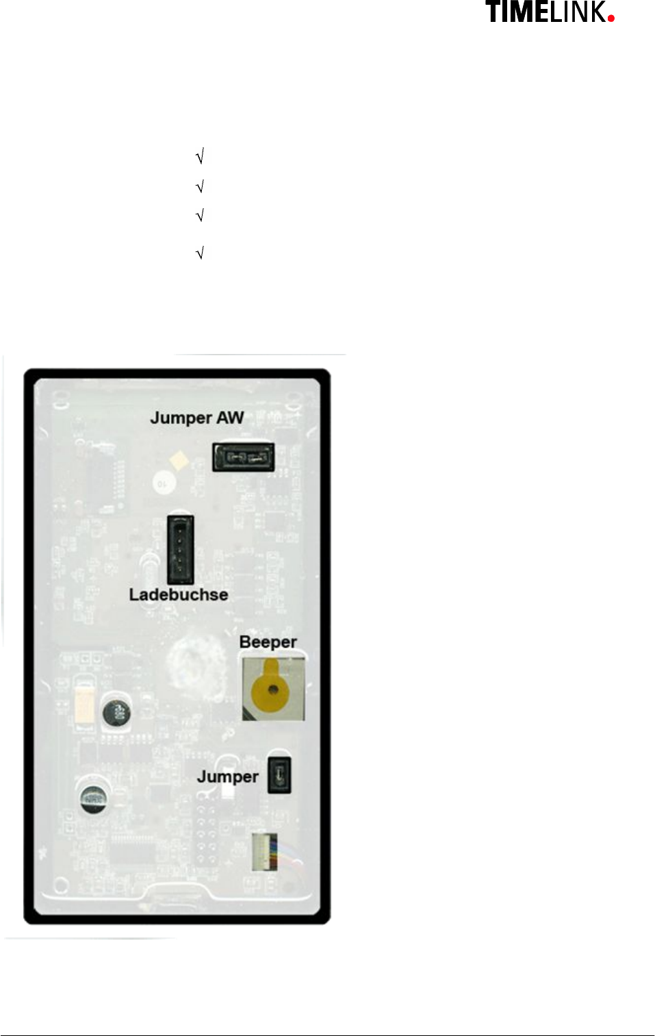
5 Wiring and Jumpers
TLR401 FP Administration and Enrollment
13
6 General Introduction
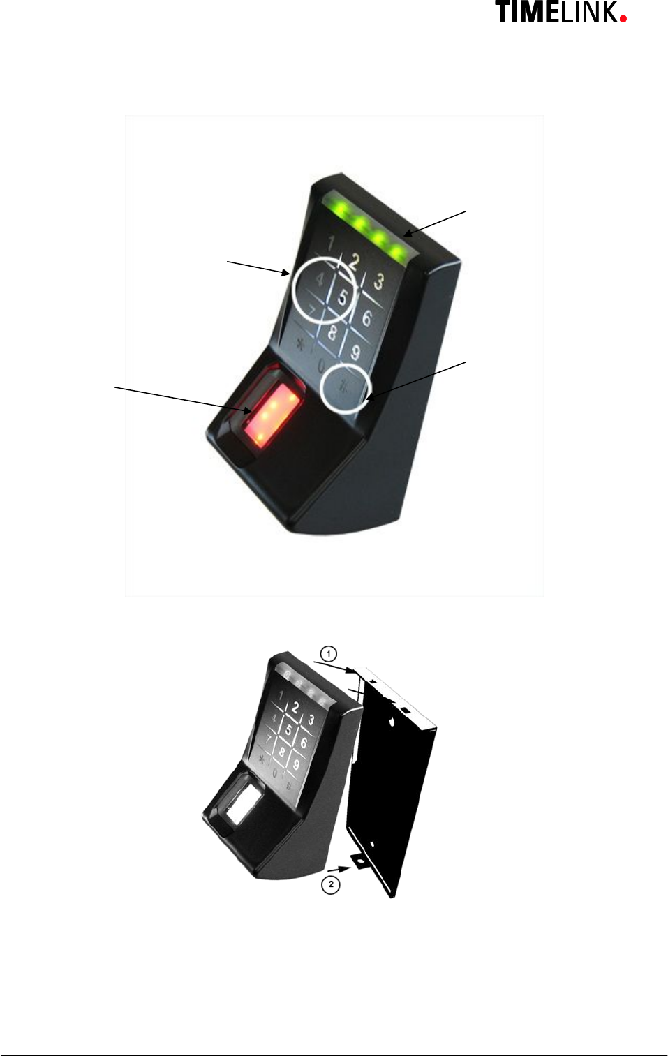
6.1 View of the control elements
LED
green
/
red
1
-
2
-
3
-
4
Finalize Button #
Fingerprint Sensor
Keypad

TLR401 FP Administration and Enrollment
14
6.2 Basics
The TLR401 is manufactured in 2 versions:
1. TLR401 with built-in biometric sensor and keypad
2. TLR401 with built-in biometrical sensor and keypad + embedded iCLASS reader
The TLR401 identifies authorized persons by scanning their fingerprints. Successful
identification sends a trigger signal to another device (BBDC) within a
protected area and is followed by a door or lock release.
Fingerprint authentication requires that the authorized persons´ fingerprints have been
enrolled beforehand and that they have been linked to a unique User ID.
Enrollment can be executed on the TLR401, which stores the collected data.
During enrollment users can choose a 2 to 9-digit numeric PIN (Personal Identification
Number).
It is only employed in operating mode Identify and provides additional user protection.
In order to prevent incorrect input, PIN and User ID will be entered 2 times each during
enrollment.
6.3 Basic operating principles
General
Pressing a key triggers a beep (0.1 seconds) and permanently illuminates the first green
LED. If no further input follows, the LED light will turn off after a defined time period.
Door Release
Beep tone and all LEDs flashing green
Green and Red / Green LEDs
Guide through menus
Red LEDs and Beeps
Generally indicate an error
Error Message
3 short beeps and all LEDs flashing red 3 times indicate an error. The desired function was
not performed.
3x Key “#”
Triple press "#" after typing errors or wait for timeout (10-30 seconds, depending on status)
to return to the starting position.

TLR401 FP Administration and Enrollment
15
6.4 Operating modes
Each TLR401 can be set up in two different main modes of operation which can be combined with
sub-operating modes.
The TLR401 operational modes are defined by function menus and adjustable codes.
Two Main Modes of Operation
Standalone: All fingerprint templates are maintained on the TLR401.
All required data can be fed into the TLR401.
Door opening code will be put out via Wiegand or an RS485 security code to
an according door control module.
Host: All fingerprint templates are maintained on the controller and, if necessary,
matched with TLR401.

TLR401 FP Administration and Enrollment
16
6.4.1 User Operation (without iCLASS):
No PIN Press Ù=> Bio-Sensor is illuminated,
Apply Finger => Red or Green lights
With PIN Press Ù=> LEDs 1 and 4 flash
Enter PIN => Bio-Sensor is illuminated
Apply Finger => Red or Green lights
6.4.2 User Operation with iCLASS:
No PIN, No iCLASS Press Ù=> Bio-Sensor is illuminated,
Apply Finger => Red or Green lights
With PIN, No iCLASS Press Ù=> LEDs 1 and 4 flash
Enter PIN => Bio-Sensor is illuminated
Apply Finger => Red or Green lights
No PIN, With iCLASS Press ÙÙ => Bio-Sensor is illuminated and off again
=> LEDs 2 and 3 flash
Apply iCLASS badge => Red or Green LEDs
With PIN, With iCLASS Press ÙÙ => LEDs 1 and 4 flash red and green
Enter PIN => LEDs 2 and 3 flash red and green
Apply iCLASS badge => Red or Green lights
After typing errors triple press # or wait for timeout
The different operating modes are configured in the administrator’s menu as described in Section 7.
TLR401 FP Administration and Enrollment
17
7 Administrator Functions
The Fingerprint Key user interface comprises keyboard, fingerprint reader and iCLASS
reader as input devices and LEDs and beepers as output devices.
The administration function users allows to adjust the different operating modes and
appropriate codes.
The device will be delivered with a default admin code (1234).
Each device has its permanent access code which is found on the shipping ticket used
during delivery. This code corresponds with the device’s unique ID. It is randomized
following a special algorithm only known to the company. The unique ID is visibly attached
to the enclosure and serves as a basis for recalculating a lost original code if necessary.
Individual codes for performing different functions can be tuned via Administrator menu.
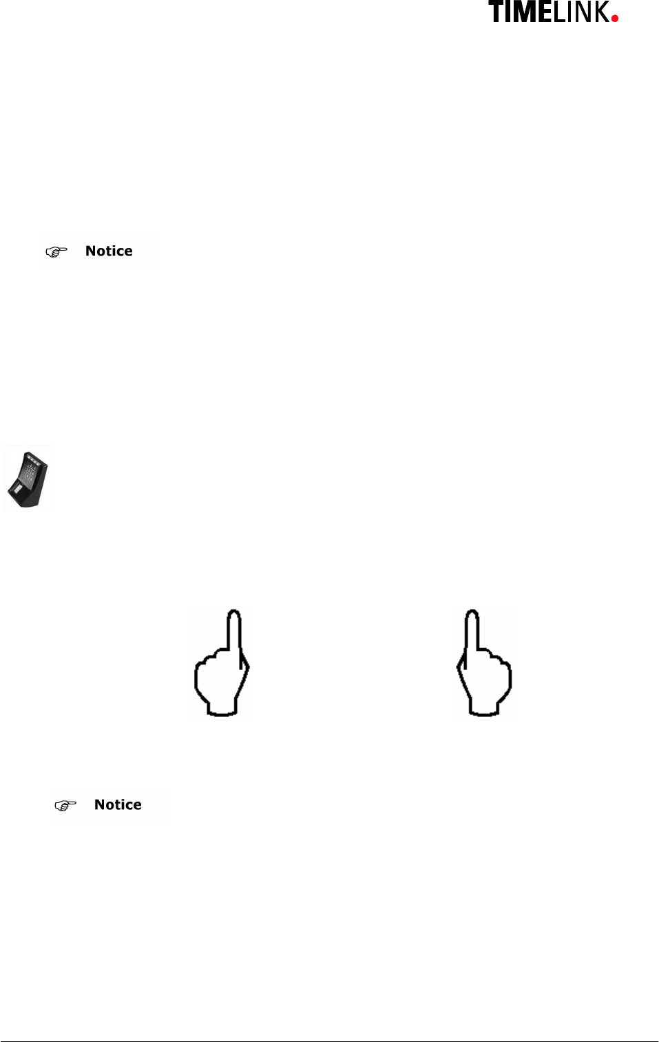
7.1 Enrollment
The TLR401 assigns 2 different fingers (e.g. left index finger, right index finger) to the
USER ID of a person.
Each of the 2 fingers must be scanned 3 times by the Fingerprint Key reader.
3 x + 3 x
For security reasons the
default
admin code should be changed.
neuen Code überschrieben werden.
Bright daylight may affect the function of the biometric sensor.
Shadowing the sensor with your hand will help.

TLR401 FP Administration and Enrollment
18
Admin Mode 99 # Green 1+2
Default admin code 1234
or enter your admin code xxxx # Green 1+2+3
Enter Enrollment Code 12 # Green 1+2+3+4
Enter User-ID xxxx # Green 1+2+3+4
(Enter twice with re-entry active) xxxx # If successful 2x Beep
· Note: A wrong length User ID, an already assigned User ID or two different IDs
(with Re-entry enabled) will prompt an alarm message and the device will go back
to its initial state.
With activated PIN Entry Green 1+4
Enter PIN xxx # Beep 1 second
With Re-Entry, once again PIN xxx # Green 2+3
Enter PIN xxx # If successful 2x Beep
7.2 Delete Single User
This function removes fingerprints allocated to a User ID from memory.
Admin Mode 99 # Green 1+2
Default admin code 1234
or enter your admin code xxxx # Green 1+2+3
Single Delete Code `````````13 # Green 1+2+3+4
User ID xxxx + # Green 1+2+3+4
Opt. further User IDs xxxx # Green 1+2+3+4
Finalize by 3x “#” ###
or Timeout
TLR401 FP Administration and Enrollment
19
7.3 Delete Database
Caution
Admin Mode 99 # Green 1+2
Default admin code 1234
or enter your admin code xxxx # Green 1+2+3
Enter Delete Code 1357 # Red 1+2+3+4 Beep
Press key Ù Ù Green 1+2+3 Beep
Red LEDs –> Error
Repeat Database delete
7.4 Change to Operation Mode Identify (Default)
Fingerprint will be compared with the saved fingerprints (identified). This process might
take longer with large databases.
Admin Mode 99 # Green 1+2
Default admin code 1234
or enter your admin code xxxx # Green 1+2+3
Operation Mode Identify 10 # Green 1+2+3+4 Beep
Finalize by 3x “#” ###
or Timeout
This function deletes and reformats the
fingerprint reader’s database for new entries.
TLR401 FP Administration and Enrollment
20
7.5 Change to Operation Mode Verify
User ID will be compared to the saved fingerprint (verified).
Admin Mode 99 # Green 1+2
Default admin code 1234
Or enter your admin code xxxx # Green 1+2+3
Operation Mode Verify 11 # Green 1+2+3+4 Beep
Finalize by 3x “#” ###
or Timeout
7.6 Change to Operation Mode User ID from iCLASS Card
Admin Mode 99 # Green 1+2
Default admin code 1234
Or enter your admin code xxxx # Green 1+2+3
Operation Mode from iCLASS 0007 # Green 1+2+3+4 Beep
Finalize by 3x “#” ###
or Timeout
7.6.1 Operation Mode User ID from iCLASS Card
In normal position the iCLASS reader is active waiting for a card to be presented, the
keypad is switched off. The User ID is read in via card, not via keypad.
The Administrator Card activates the keypad for Administrator function. Entry "99#"
functions the same setting the mode for Administrator Code input (Level-2), the green
LED 1 and LED 2 flash.
TLR401 FP Administration and Enrollment
21
7.6.2 Verify with iCLASS Card
This operation mode stores fingerprint and User ID together. The User ID must be read
from the iCLASS Card and then fingerprint scan will follow. If the finger’s User ID
matches the User ID stored, a release action is triggered.
Procedure:
The user presents his card with his User ID. If the User ID is found, the fingerprint reader
flashes for a finger to be presented. If the finger matches the User ID associated a beep
is heard and all LEDs flash green to indicate release.
A finger that does not fit the data records will cause the fingerprint reader lights to turn
off.
If no User ID is detected means then no action will take place.
7.6.3 Enroll with iCLASS
Same procedure as described above except the User ID is replaced by presenting the
iCLASS card instead of keypad entry.
To exit this function menu the administrator card needs to be presented or wait for a
timeout to get back to the initial state.
7.7 Adjust Admin Code
Admin Mode 99 # Green 1+2
Default admin code 1234
or your admin code xxxx # Green 1+2+3
Function menu 14 # Green 1+2 Beep
Adjust admin code 15 # Green 2+3 Beep
(Default = 1234) 4 - 8 digits # Green 1+2 Beep
Finalize by 3x “#” ###
or Timeout
TLR401 FP Administration and Enrollment
22
7.8 Define the number of digits for the User ID
Admin Mode 99 # Green 1+2
Default admin code 1234
Or enter your admin code xxxx # Green 1+2+3
Function menu 14 # Green 1+2 Beep
Number digits User ID 16 # Green 3+4 Beep
(Default = 5) 2 - 9 digits # Green 1+2 Beep
Finalize by 3x “#” ###
or Timeout
7.9 Enable PIN mode and defining its number of digits
Admin Mode 99 # Green 1+2
Default admin code 1234
or enter your admin code xxxx # Green 1+2+3
Function menu 14 # Green 1+2 Beep
Enable PIN / number digits 21 # Green 3+4 Beep
Default = 0 (PIN disabled) 2 - 9 digits # Green 1+2 Beep
Finalize by 3x “#” ###
or Timeout
TLR401 FP Administration and Enrollment
23
7.10 Enable Re-Entry of PIN and User ID
Admin Mode 99 # Green 1+2
Default admin code 1234
or enter your admin code xxxx # Green 1+2+3
Function menu 14 # Green 1+2 Beep
Re-Entry PIN + User ID 22 # Green 3+4 Beep
Enable 1 # Green 1+2 Beep
Disable (Default) 0 # Green 1+2 Beep
Finalize by 3x “#” ###
or Timeout
7.11 Enable iCLASS Mode
Admin Mode 99 # Green 1+2
Default admin code 1234
or enter your admin code xxxx # Green 1+2+3
Function menu 14 # Green 1+2 Beep
iCLASS Menu 24 # Green 3+4 Beep
Enable 1 # Green 1+2 Beep
Disable (Default) 0 # Green 1+2 Beep
Finalize by 3x “#” ###
or Timeout
TLR401 FP Administration and Enrollment
24
7.12 Learn iCLASS admin card
Admin Mode 99 # Green 1+2
Default admin code 1234
or enter your admin code xxxx # Green 1+2+3
Function menu 14 # Green 1+2 Beep
Menu: learn iCLASS admin card 0009 # Green 1+4 Beep
Apply card Beep
Device is in operation mode with iCLASS User ID. Other operation modes can be
adjusted.
Caution
7.13 Define door opening time
Admin Mode 99 # Green 1+2
Default admin code 1234
or enter your admin code xxxx # Green 1+2+3
Function menu 14 # Green 1+2 Beep
Door opening time 17 # Green 1+4 Beep
3 digits xxx # Green 1+2 Beep
Example: 100 = 10 sec.
030 = 3 sec. (Default)
Finalize by 3x “#” ###
or Timeout
No Timeout
In case of failure reader is in iCLASS Mode without
admin card. This status can only be reversed by
hardware reset.
TLR401 FP Administration and Enrollment
25
7.14 Adjust Standalone output mode (e.g. Wiegand 37 bit , 26 bit or RS485 security
mode)_
Admin Mode 99 # Green 1+2
Default admin code 1234
or enter your admin code xxxx # Green 1+2+3
Function menu 14 # Green 1+2 Beep
Output menu 19 # Green 3+4 Beep
Wiegand 37bit Facility Code 0 # Green 1+2 Beep
(Default)
Wiegand 26bit Facility Code 1 # Green 1+2 Beep
Finalize by 3x “#” ###
or Timeout
Query inputs in Standalone Mode, as long as the inputs are addressed the respective outputs
are active.
opto-in-1 = green LED
opto-in-2 = Beeper
opto-in-3 = red LED
7.15 Adjust HID Wiegand facility code
Admin Mode 99 # Green 1+2
Default admin code 1234
or enter your admin code xxxx # Green 1+2+3
Function Menu 14 # Green 1+2 Beep
Facility code menu 20 # Green 3+4 Beep
1 – 5 digits # Green 1+2 Beep
e.g. Wiegand 37bit (Default = 830) 0 … 65535 #
Wiegand 26bit (Default = 1) 0 … 255 #
Finalize by 3x “#” ###
or Timeout
TLR401 FP Administration and Enrollment
26
7.16 Setting the display in Standalone mode
Admin Mode 99 # Green 1+2
Default admin code 1234
or enter your admin code xxxx # Green 1+2+3
Function menu 14 # Green 1+2 Beep
Display menu 23 # Green 3+4 Beep
Disable 1 # Green 1+2 Beep
Enable (Default) 0 # Green 1+2 Beep
Finalize by 3x “#” ###
or Timeout
7.17 Loading firmware (for authorized service personal only)
Admin Mode 99 # Green 1+2
Default admin code 1234
or enter your admin code xxxx # Green 1+2+3
Function menu 14 # Green 1+2 Beep
Menu firmware 0001 # Green 1-4
In order to load a new release of the TLR401’s firmware it must be set to its loading mode.
First turn off the reader and then plug in the USB cable to X3 and unplug jumper X11.
Then turn on the TLR401 and proceed to the loading menu as indicated above.
Load firmware from your computer.
When finished unplug the USB cable, set jumper X11 and turn off and back on the TLR401.
TLR401 FP Administration and Enrollment
27
7.18 Reset to defaults
Admin Mode 99 # Green 1+2
Default admin code 1234
or enter your admin code xxxx # Green 1+2+3
Function menu 14 # Green 1+2 Beep
Menu reset to defaults 0000 #
Device resets to all defaults
and reboots
7.19 Hardware reset
There are operating modes in combination with iCLASS that lock the keypad.
If an iCLASS admin card got lost, a reset can be the appropriate reaction. Connecting
Wiegand-Out-D0 (brown) to Opto-In-1 (blue) during a turn-on procedure sets the device
back to default mode.
All other settings will be retained.

TLR401 FP Administration and Enrollment
28
8 Online Operation with Host
With this setup the host access control system manages the TLR401.
While enrolling, no operation with the key pad is needed, except for presenting the finger
that must be enrolled.
For security reasons the identification of the templates is processed by the TLR401.
Along with fingerprint-based operation, the TLR401 can be used with iCLASS cards.
Instead of using a finger, the user can be identified by his iCLASS card for if his finger is
unreadable.
Templates are organized by the host and can be distributed to the connected TLR401
readers .
The PIN code is not processed locally. In the case of a successful identification the TLR401
will send a message to the host.
The host controls the door opener.
The administration of the TLR401 is done on the host system.
The host system processes signaling, e.g. release or reject (see host manual)
“Always Open"
(all 4 green LEDs are permanently on, further inputs are accepted)
"Always Closed"
(all 4 red LEDs are permanently on, no further inputs are accepted)
Online/Offline display (can be switched off by the host)
Offline = Red LED flashes 4 times
Online = Green LED flashes 4 times
While the device is offline no further inputs are accepted.
Inputs are also temporarily blocked when the biometric reader is loading data from the host.
This is indicated by the red flashing LEDs 2 and 3.

TLR401 FP Administration and Enrollment
29
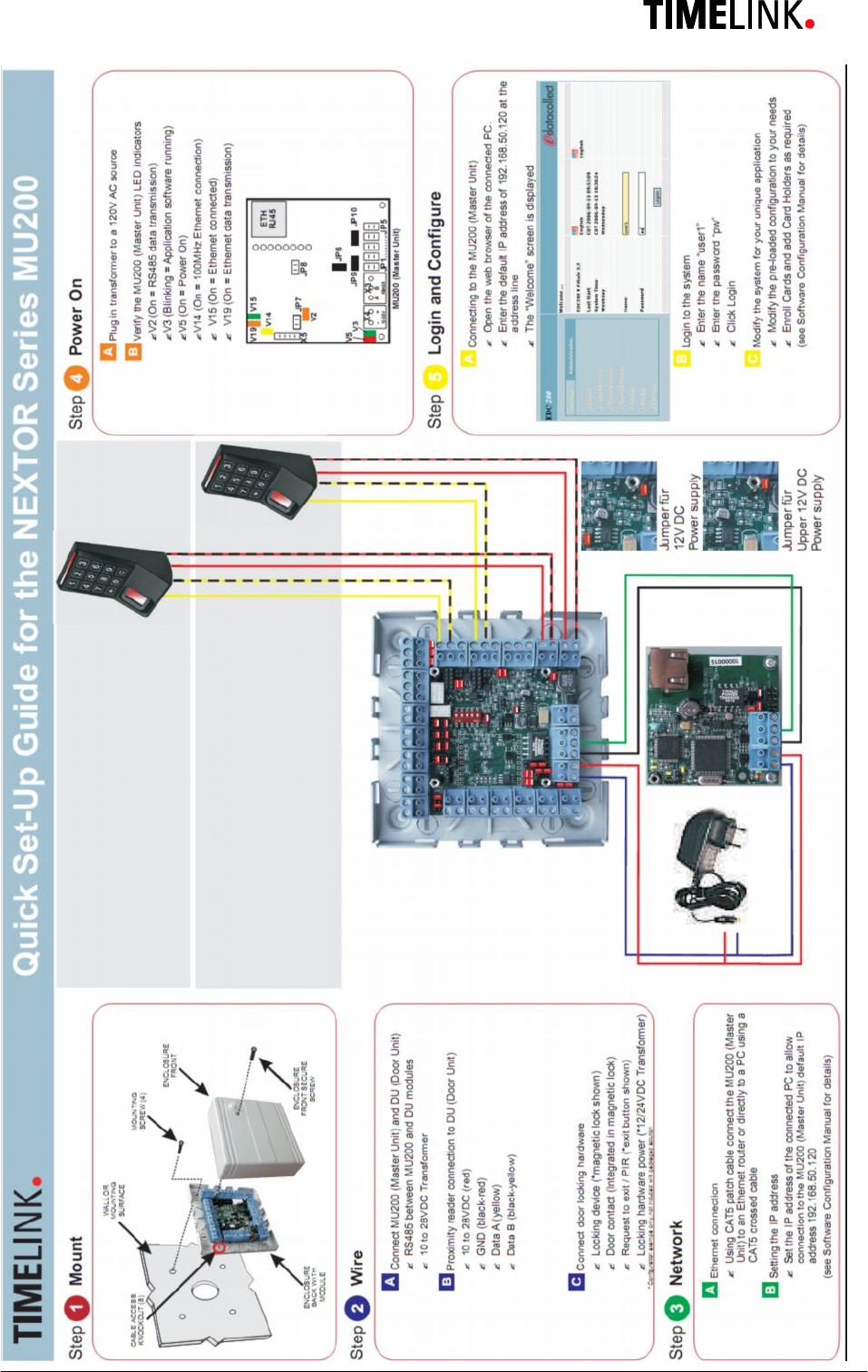
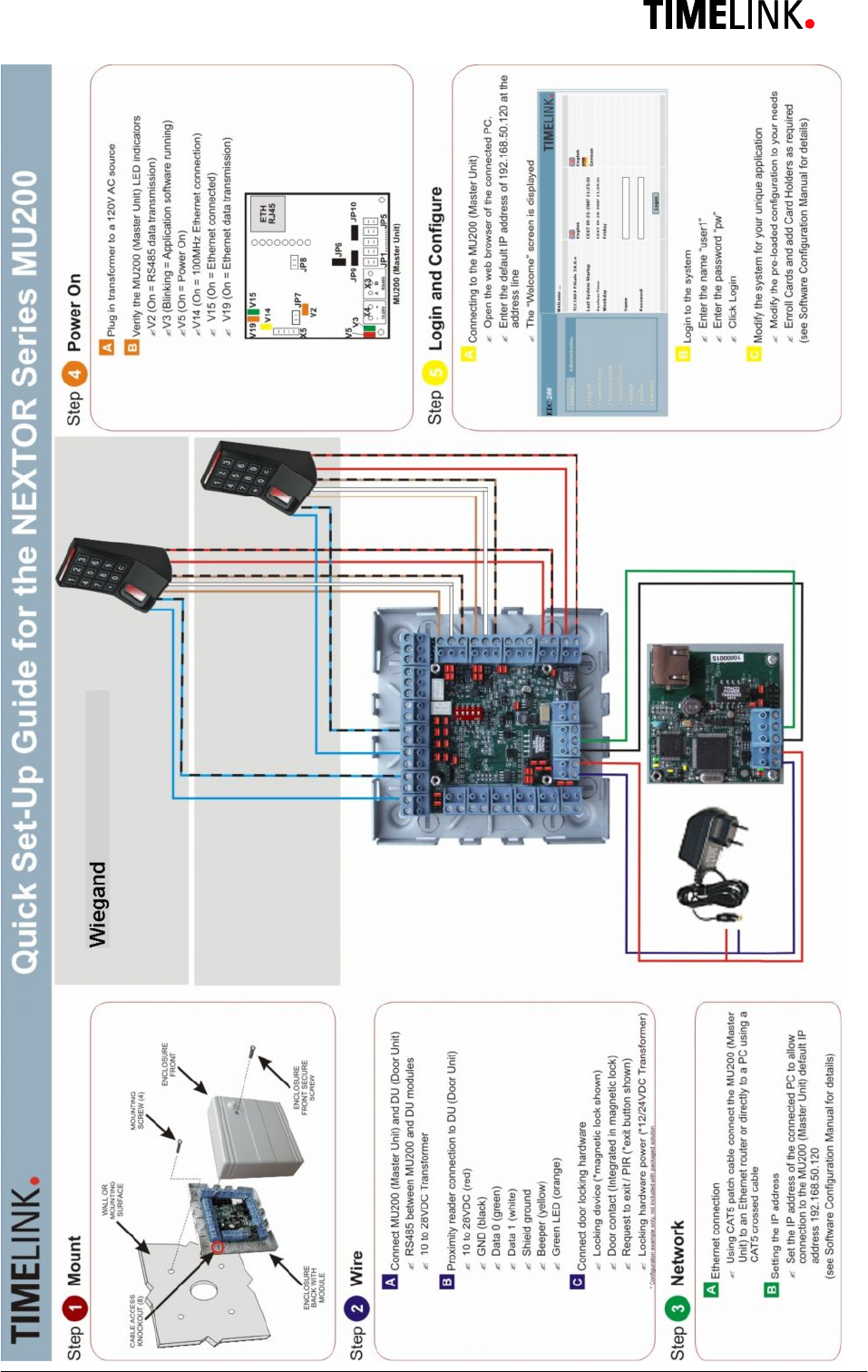
8.1 Connecting the TLR401 to the door unit (BDC)
Generally:
The number of TLR401 connected to one BDC is limited to two.
Physically :
The devices are connected by a so called bus connection, which means there is one long
cable with short stubs to the devices. Long can mean up to 1300 yards and short can
mean up to 5 yards (these are approximate values). The rule of thumb is the shorter the
long cable the shorter the stubs.
The two furthermost devices must have termination resistors (these are built in on the BDC
and TLR401 and can be activated by two jumpers, see hardware manuals).
If there are two TLR401 devices, it is best to connect one on the BDC reader terminal-1,
the other on the BDC reader terminal-2. The BDC is in the middle of the bus, which means
there are no termination resistors for the BDC, but both TLR401s need their termination
resistors activated.
With one TLR401 connected to the BDC both the BDC and the TLR401 must have their
termination resistors activated.
Logically:
On a bus line the devices are distinguished by a device ID (address).
The TLR401 devices have a built in unique-number. The BDC recognizes all available
unique numbers on the bus line.
On the TLR401 you will find the unique-number printed as a 12 digit binary number.
In order to avoid confusion it might be helpful for the installer to create a list of device
unique-numbers and their respective locations.
The BDC assigns the two IDs 0 and 1 to the recognized unique-numbers according to the
following logic:
The BDC recognizes two unknown unique-numbers =>
The lower unique-number is assigned to ID-0.
The higher unique-number is assigned to ID-1.
The BDC recognizes an already known unique-number and one unknown unique-
number =>
The known unique-number will keep its ID-assignment.
The unknown unique-number will be assigned the available ID (0 or 1).
Both unique-numbers are known by the BDC =>
The devices keep their ID assignment.

TLR401 FP Administration and Enrollment
30
Possible operations on the Web Interface in regards to the unique-numbers
Display the recognized unique-numbers and their ID assignments.
Reset the existing assignments and a new assignment according to specified logic.
Free assignment of unique-numbers and IDs.

TLR401 FP Administration and Enrollment
31
9 Maintenance
Caution
Danger of electric shock! Disconnect the device from the
power supply before opening and before connecting cables.
9.1 Customer Service
First Response
identify defects and
causes
Phone the Timelink hotline in the event of any malfunctions.
Note the following points before placing your call:
· Serial number of the TLR401
· Unique-number
· Customer number
· What action have you already taken to rectify the defect?
· LED condition
· Device and host errors
· What action happened before the error appears?
· What did you do for correcting the error?
9.2 Repairs
Careful
You may only undertake repair work after coordination with
Timelink International
Repairs must be performed professionally. Use genuine spare
parts only.
9.3 Warranty, Limitation on Liability to Third Parties
In accordance with national statutory regulations at the place
where the device is installed

TLR401 FP Administration and Enrollment
32
10 Appendix
10.1 TLR401 Configuration Examples
10.1.1 Setting the Reader to Fingerprint and iCLASS Mode
Enter Details
1. 99 # Admin mode
2. 1234 # Enter admin code (here the default code)
3. 14 # Open Function menu
4. 24 # Open iCLASS menu (default = 0, disabled)
5. 1 # Enable iCLASS mode
The TLR401 is now set to iCLASS mode.
Once the user enters Ù Ù the reader is ready to read the iCLASS card and indicates this by LEDs 2+3
flashing red and green.
Entering Ù the user still can be identified through the fingerprint module.
10.1.2 Enabling the PIN Mode
If you wish to use the reader in PIN mode it is imperative in standalone mode to enable the PIN mode
before users enroll so that each user can enter his individual PIN in the enrollment process.
Enter Details
1. 99 # Admin mode
2. 1234 # Enter admin code (here the default code)
3. 14 # Open Function menu
4. 21 # Open PIN menu (default = 0, disabled)
5. 2-9 # Enable PIN mode and define at the same time the number of digits of at least 2
digits to a maximum of 9 digits.
The TLR401 is now set to PIN mode.
Once the user enters Ù the reader expects the user to enter his personal PIN before identifying the finger
and indicates this by LEDs 1+4 flashing red and green.
Enrollment now will entail first entering the User ID then the PIN and then reading two fingers three times
each.
10.1.3 Enrollment with PIN
Enter Details
1. 99 # Admin mode
2. 1234 # Enter admin code (here the default code)
3. 12# Enable enrollment
4. e.g. 00001 # Enter User ID (here 5 digits, the default)
5. e.g. 0001 # Enter PIN (here 4 digits)
6. 3 x finger 1 Two fingers (e.g. thumbs, left & right) are read three times each
7. 3 x finger 2 Apply the second finger three times
The user is stored on the database of the TLR401. The reader now will identify the user by his PIN and his
fingerprints.

TLR401 FP Administration and Enrollment
33
10.2 Quick Guide to Admin Functions
99 # Enable admin mode
1234 # Enter admin code (or enter individual code)
12 # Enroll
13 # Delete one user (User ID)
1357 # Ù Delete entire database
10 # Identify
11 # Verify
0007 # Verify with iCLASS
14 # Function menu
15 # New admin code (4-8 digits) (default = 1234)
16 # Number of digits: User ID (2-9 digits) (default = 5)
21 # Number of digits: PIN (2-9 digits)
0 = disabled (default =0)
22 # Re-entry of PIN and User ID
0 = disabled
1 = enabled (default = 0)
24 # iCLASS mode
0 = disabled
1 = enabled (default = 0)
0009 # Learn iCLASS admin card
17 # Door opening time
3 digits with leading zeros (default = 030 => 3 sec)
19 # Output mode
0 = Wiegand 37 bit
1 = Wiegand 26 bit (default = 0)
20 # HID Wiegand facility code
0 - 65535 = 37 bit (default = 830)
0 - 255 = 26 bit (default = 1)
23 # Release local display
0 = enable
1 = disable (default = 0)
0001 # Load bio-sensor firmware
0000 # Reset configuration to original settings

TLR401 FP Administration and Enrollment
34
10.3 Allocation of the cable
connector details color of wire
on board
X1
1 - Screen Screen Wire
2 - RS485B black of yellow
3 - RS485A yellow
4 - tamper switch-NO green
X4
1 - opto-in-2 black of blue
2 - opto-in-3 black of green
3 - DC in + 12...24V red
4 - DC in (–) black of red
X5
1 - Viso common black of brown
2 - Wiegand out D1 white
3 - Wiegand out D0 brown
4 - opto-in-1 blue
Remarks:
The wires are arranged in twisted pairs, one colored wire with a black wire respectively.
RS485: The last device in the line must be provided with 2 jumpers in JP1.
Opto-in-x Goes active, when connected to "Viso common" (e.g. in "stand alone
Wiegand" mode "opto-in-1" enables the green, "opto-in-2" the red LEDs and "opto-in-3" the
beeper).
Wiegand out is open collector to "-Viso common"
Tamper switch switches to "-Viso common"

TLR401 FP Administration and Enrollment
35
10.4 Wiring requirements
Notice:
Do not lay the data lines parallel to high voltage cables. If unavoidable lay the lines in closed steel
tubes and keep a distance of 3 ft. for the protection from electromagnetic interference.
RS485
Shielded twisted pair cable (1300 yards max) e.g.:
1. 2x2 strands litz wire AWG24 (0.4 kcmil)
2. J-Y(ST)Y 2x2x0,6
3. CAT 5 ... 7 STP (Shielded Twisted Pair)
Wiegand
Non-twisted shielded cable (150 meters max) e.g.:
1. 10 strands shielded litz wire AWG22 (0.64 kcmil)
For shorter distances or using higher supply voltage:
2. 8 strands litz AWG24 (0.4 kcmil)
Consider whether or not to supply power with the data cable. Long distances require an increased
diameter of the cable. Supplying power locally or having an extra power cable may be preferable.
Because of voltage drop over longer distances the 24V power supply may be the appropriate
choice.
Example for calculating the power supply wiring:
1. AWG22 cable (0,34 mm2):
Loop resistance ca 115 ohm / km
TLR401 current with 12V = 0,2A
Cable length 150m
Voltage drop: 115 ohm / km * 0.15km * 0,2A = 3.45V
The supply voltage should be ≥ 15V in this case
2. AWG24 cable (0,25 mm2):
Loop resistance ca 180 ohm / km
TLR401 current with 12V = 0,2A
Cable length 150m
Voltage drop: 180 ohm / km * 0.15km * 0,2A = 5,4V
The supply voltage should be ≥ 18V in this case
TLR401 FP Administration and Enrollment
36
TLR401 FP Administration and Enrollment
37