e DATA TLR401 Fingerprint keypad User Manual TLR401 Manual
e-DATA GmbH Fingerprint keypad TLR401 Manual
UserManual.wiki
>
e DATA
>
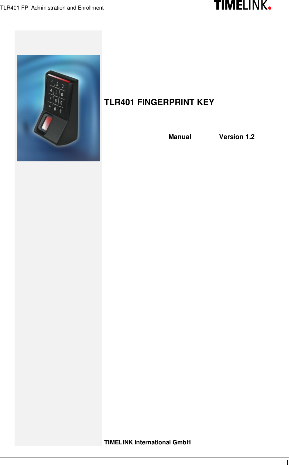
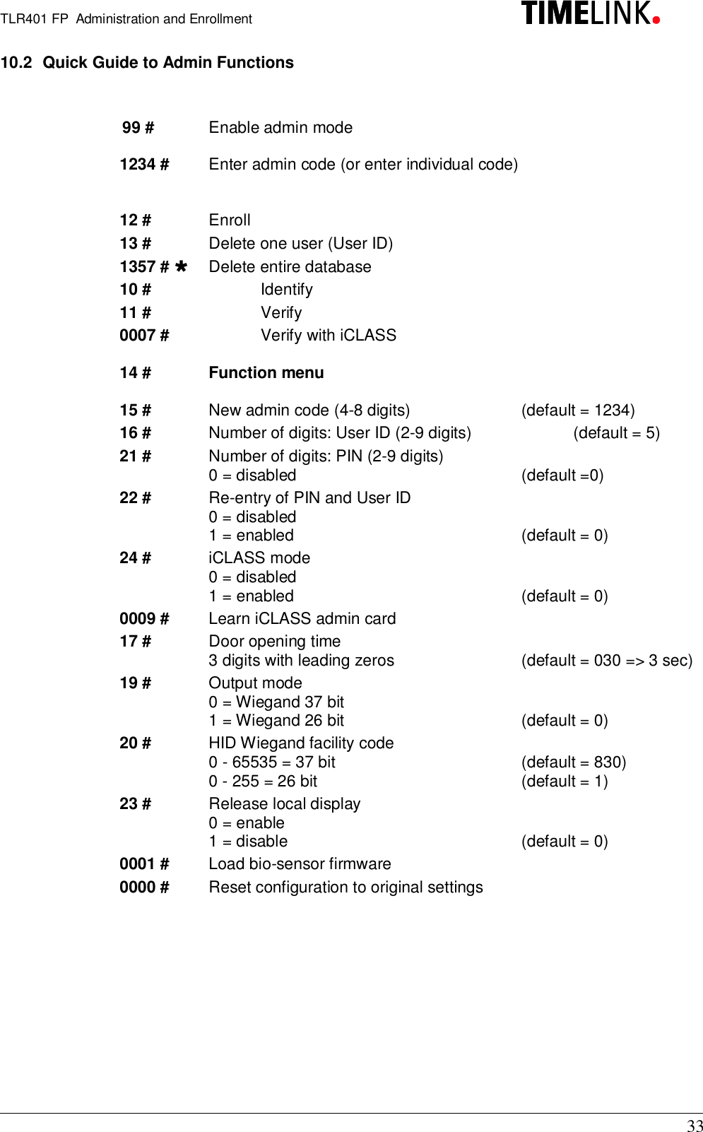
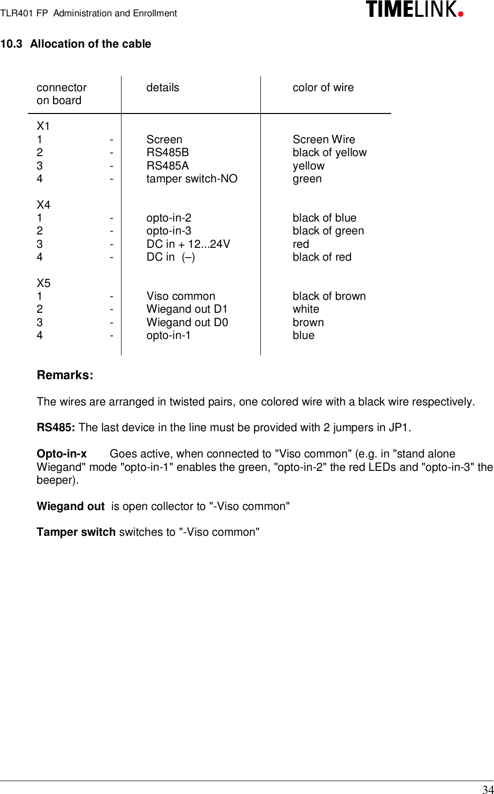
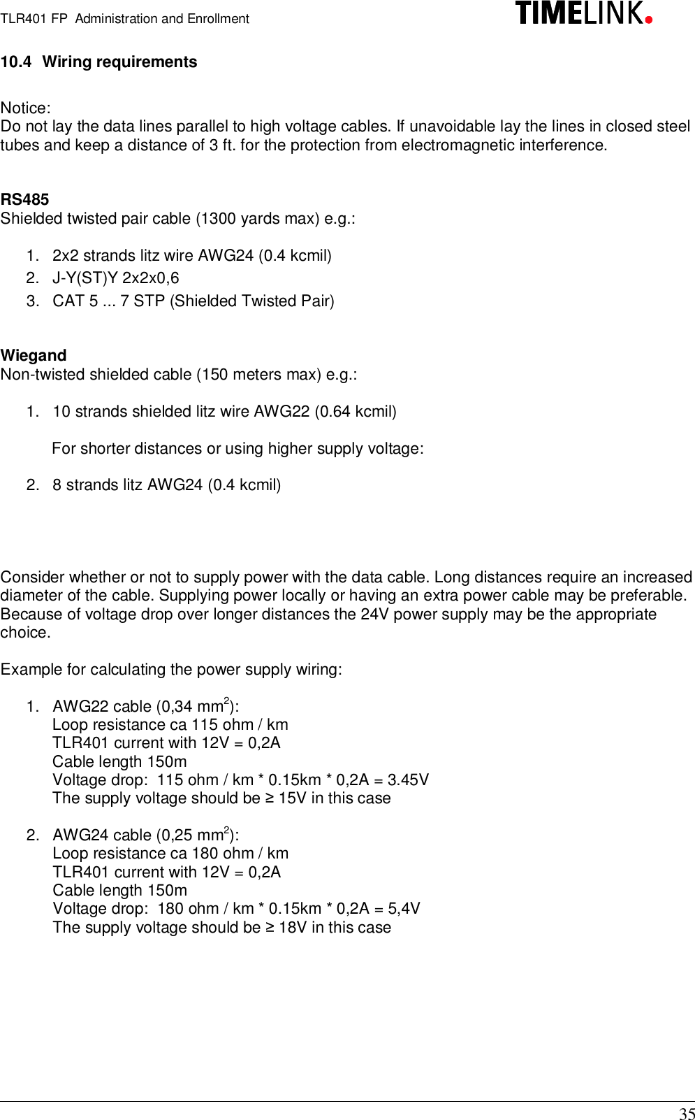
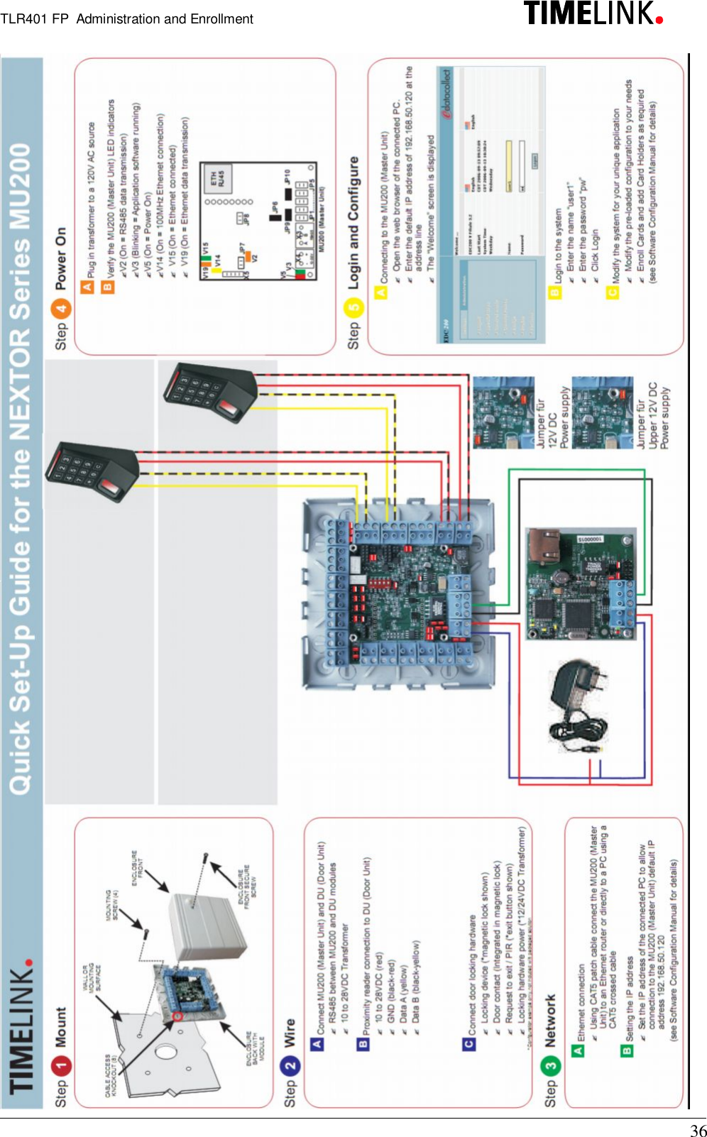
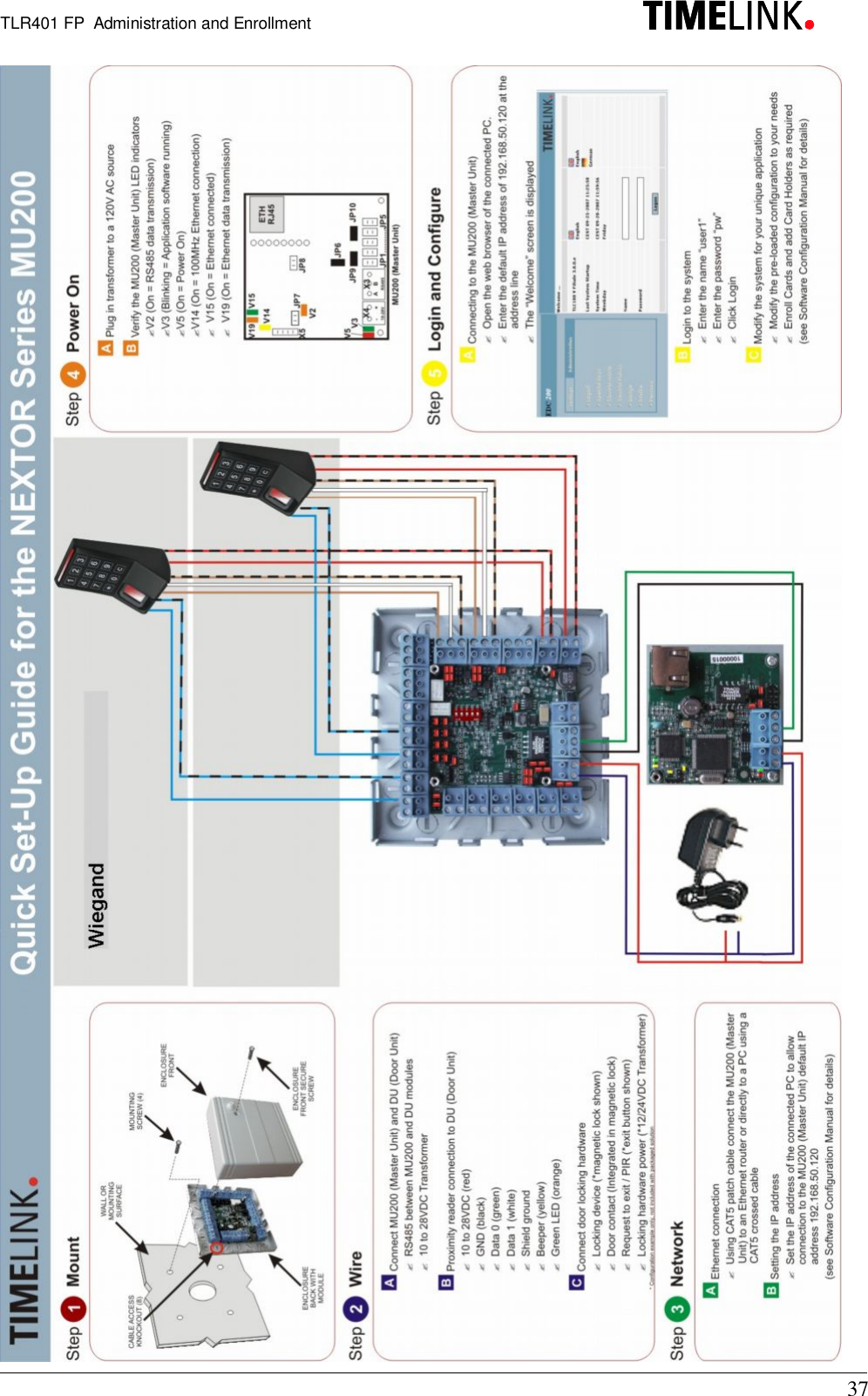
TLR401 User Manual
>
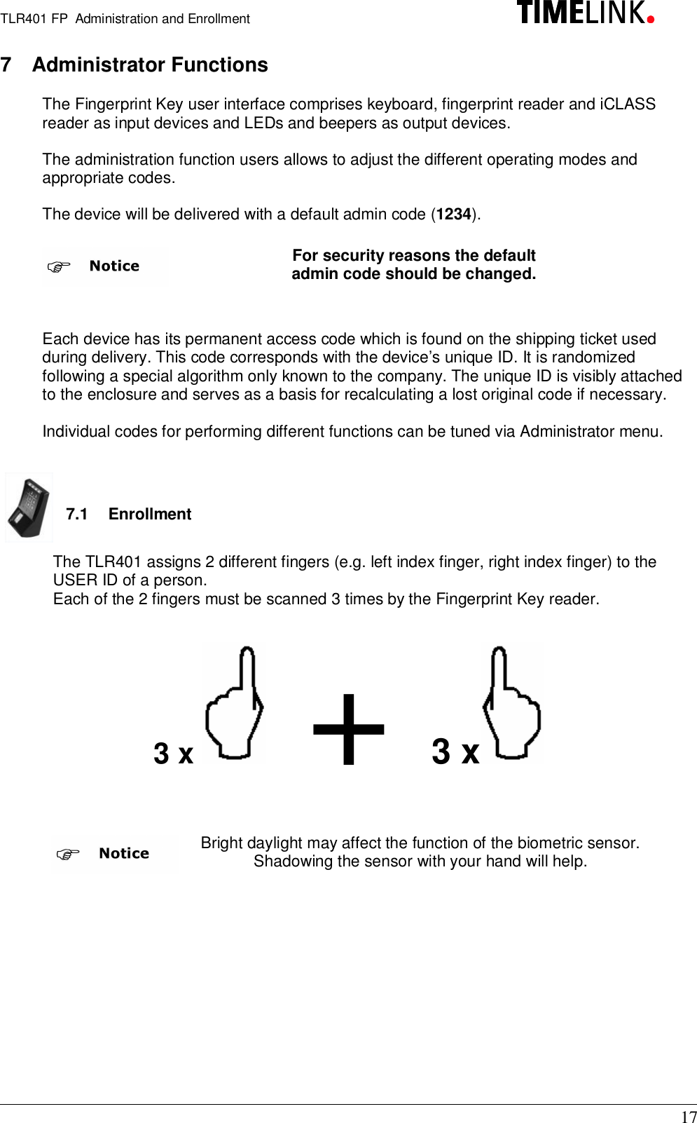
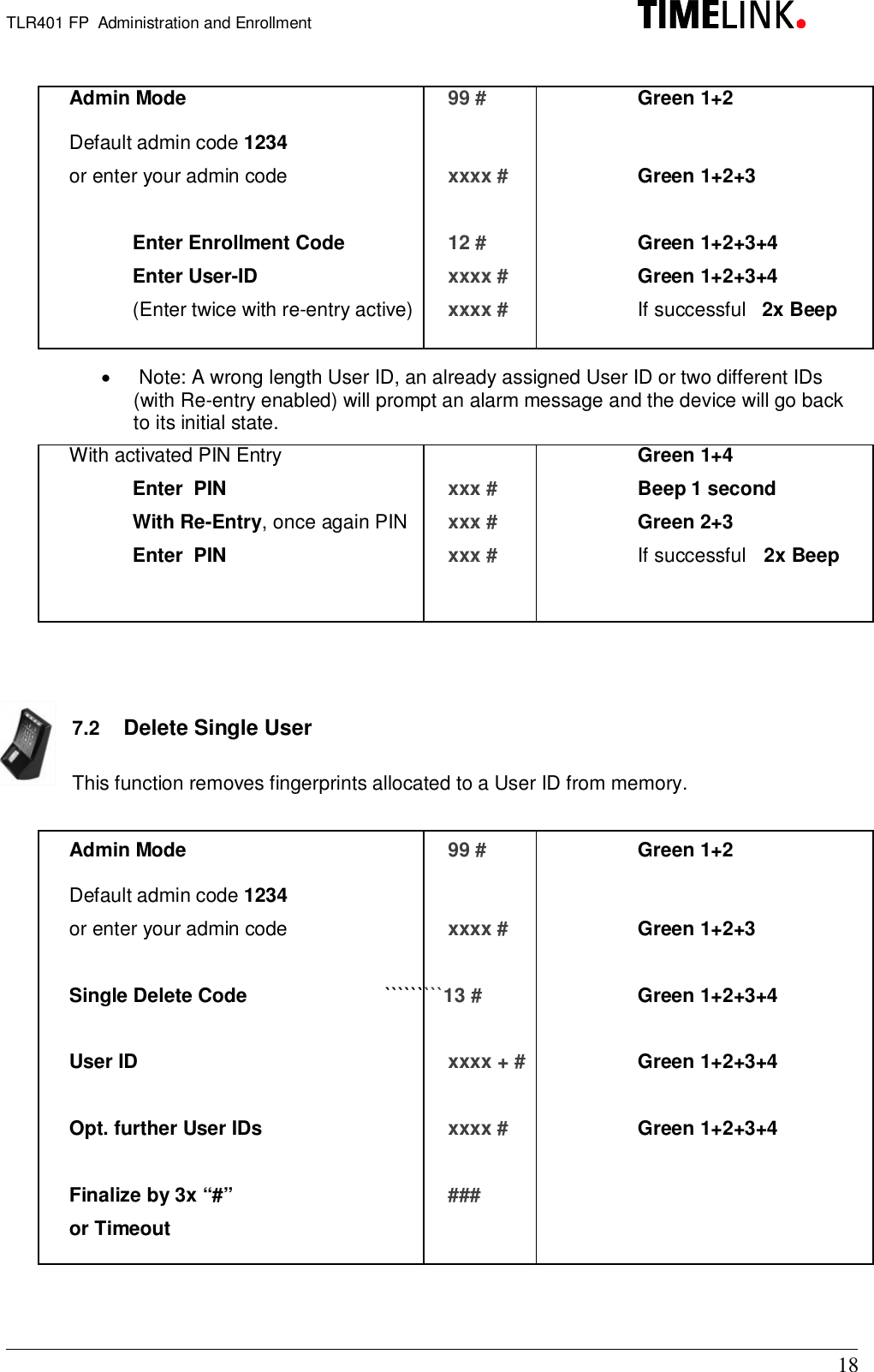
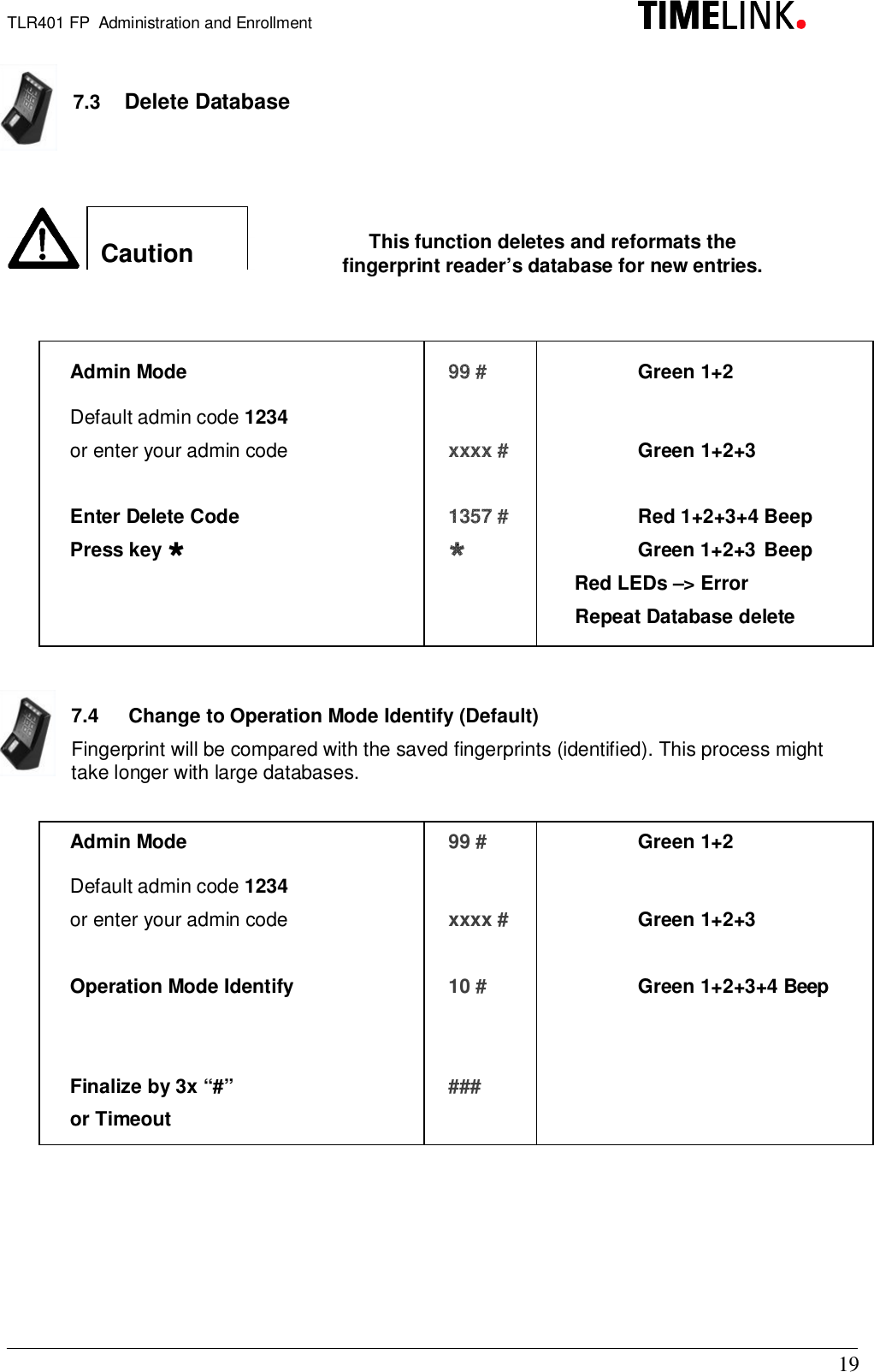
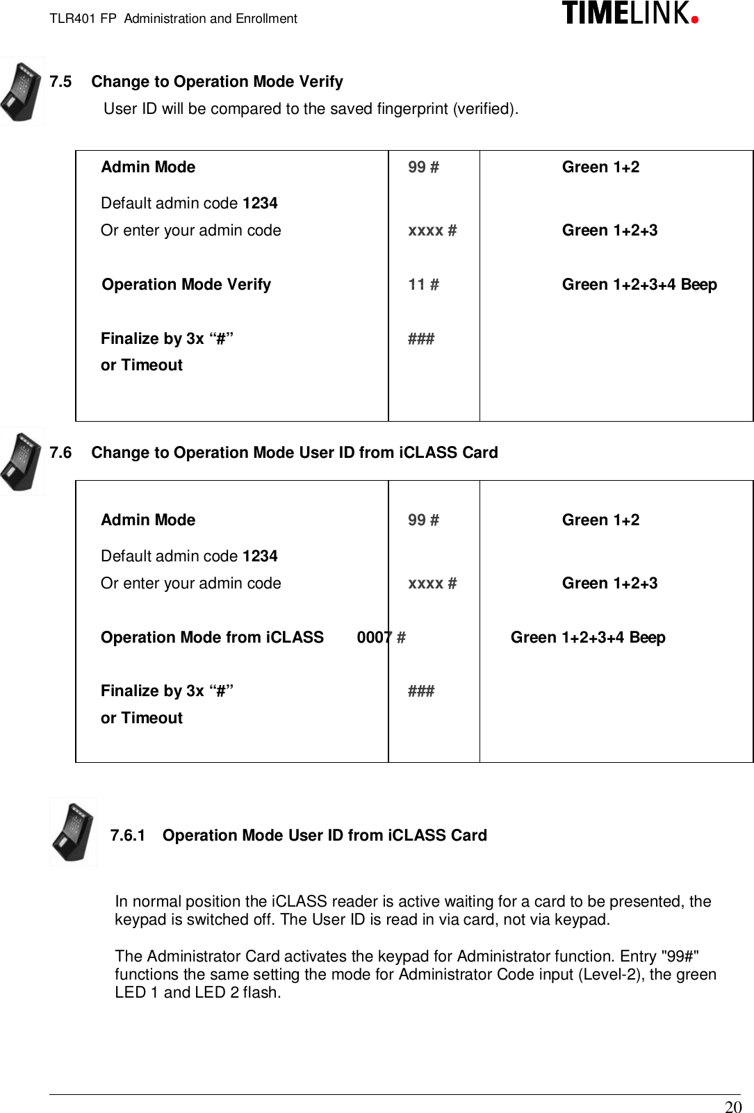
Users manual
Contents
1.
Users manual
2.
Information about modifications
Users manual
Navigation menu
Upload a User Manual
Namespaces
Wiki Guide
HTML
PDF
Info
Views
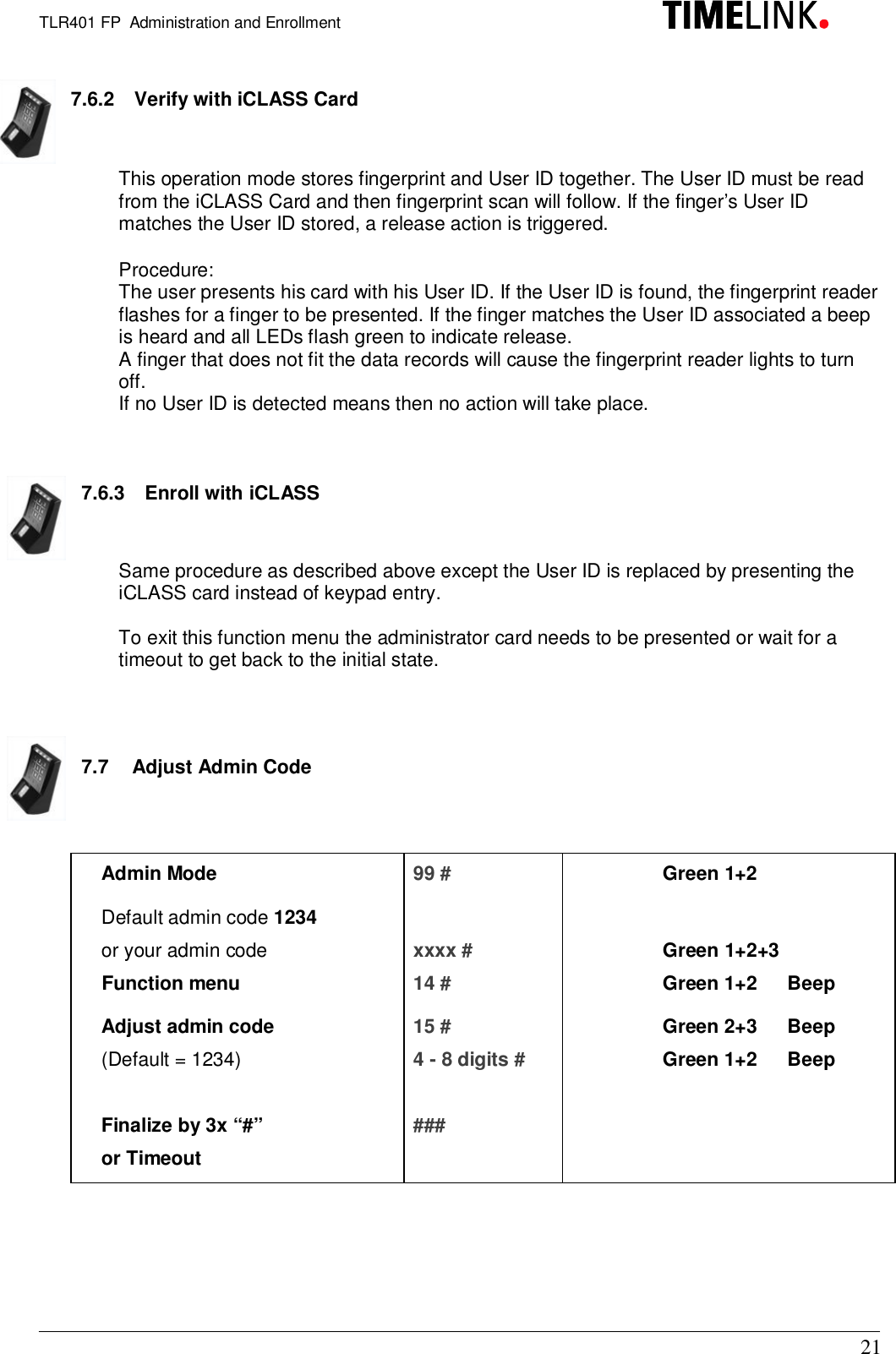
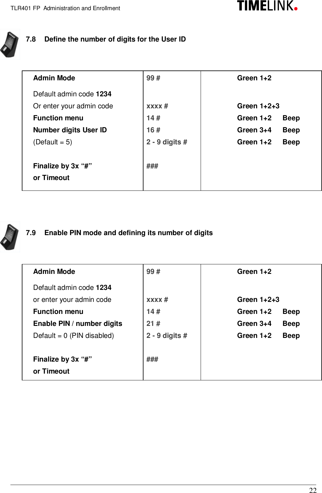
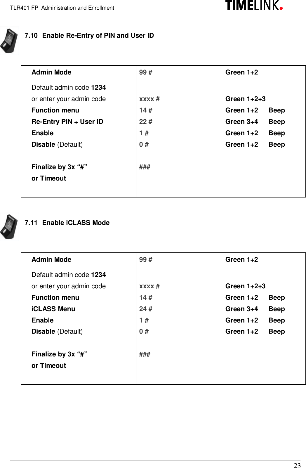
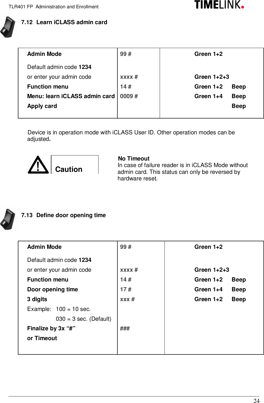
User Manual
Discussion / Help
Navigation