e DATA TLR401 Fingerprint keypad User Manual Information about modifications
e-DATA GmbH Fingerprint keypad Information about modifications
e DATA >
Contents
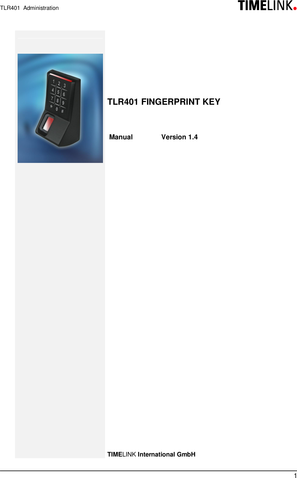
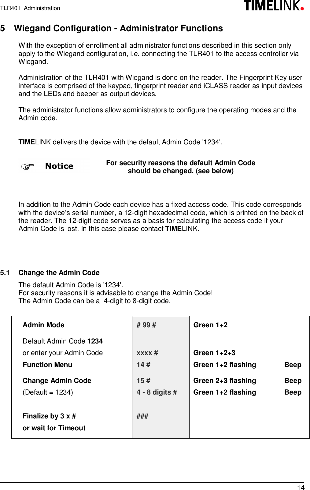
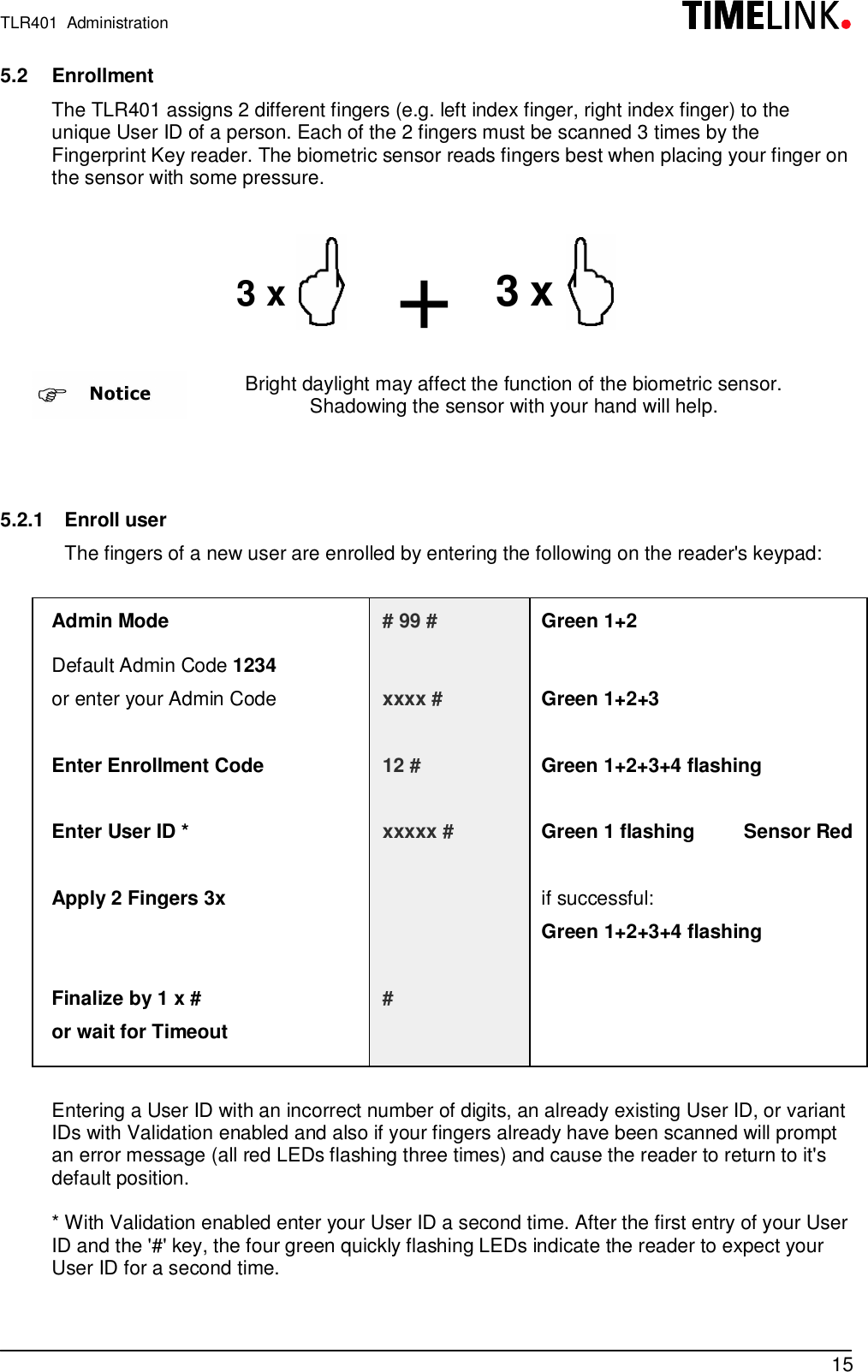
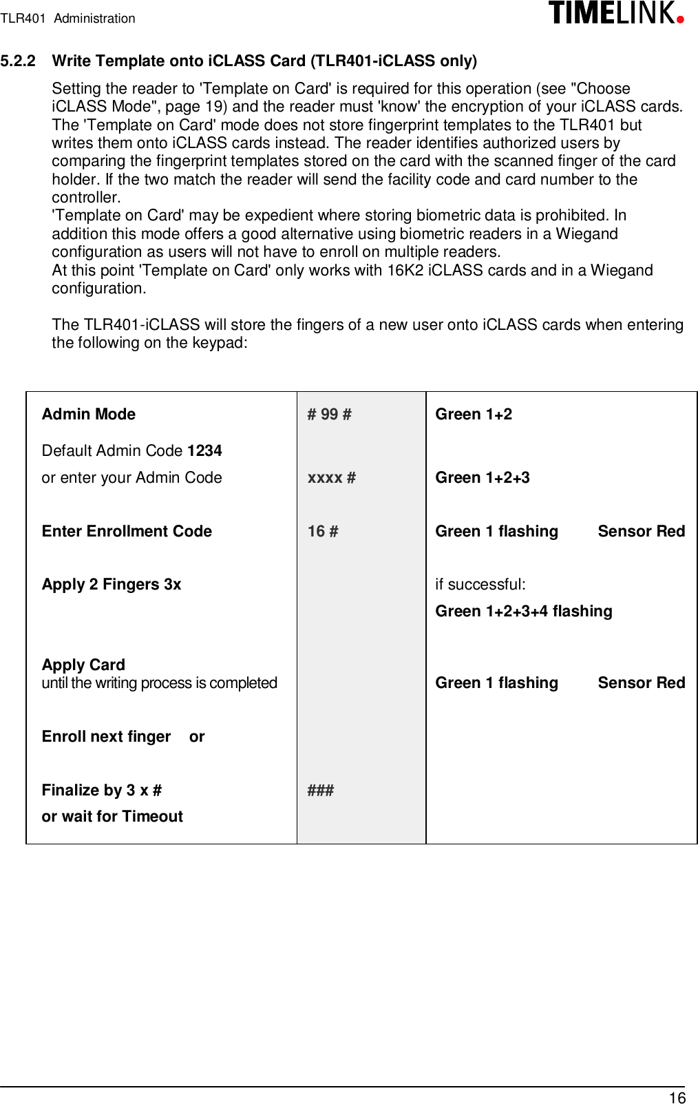
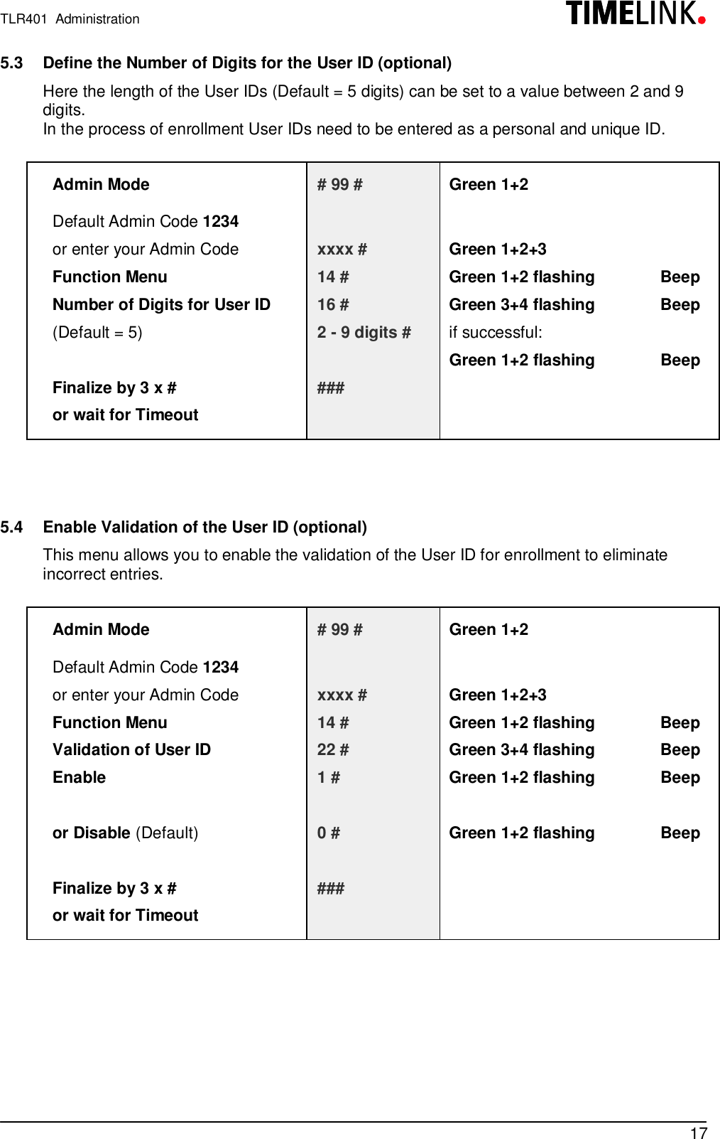
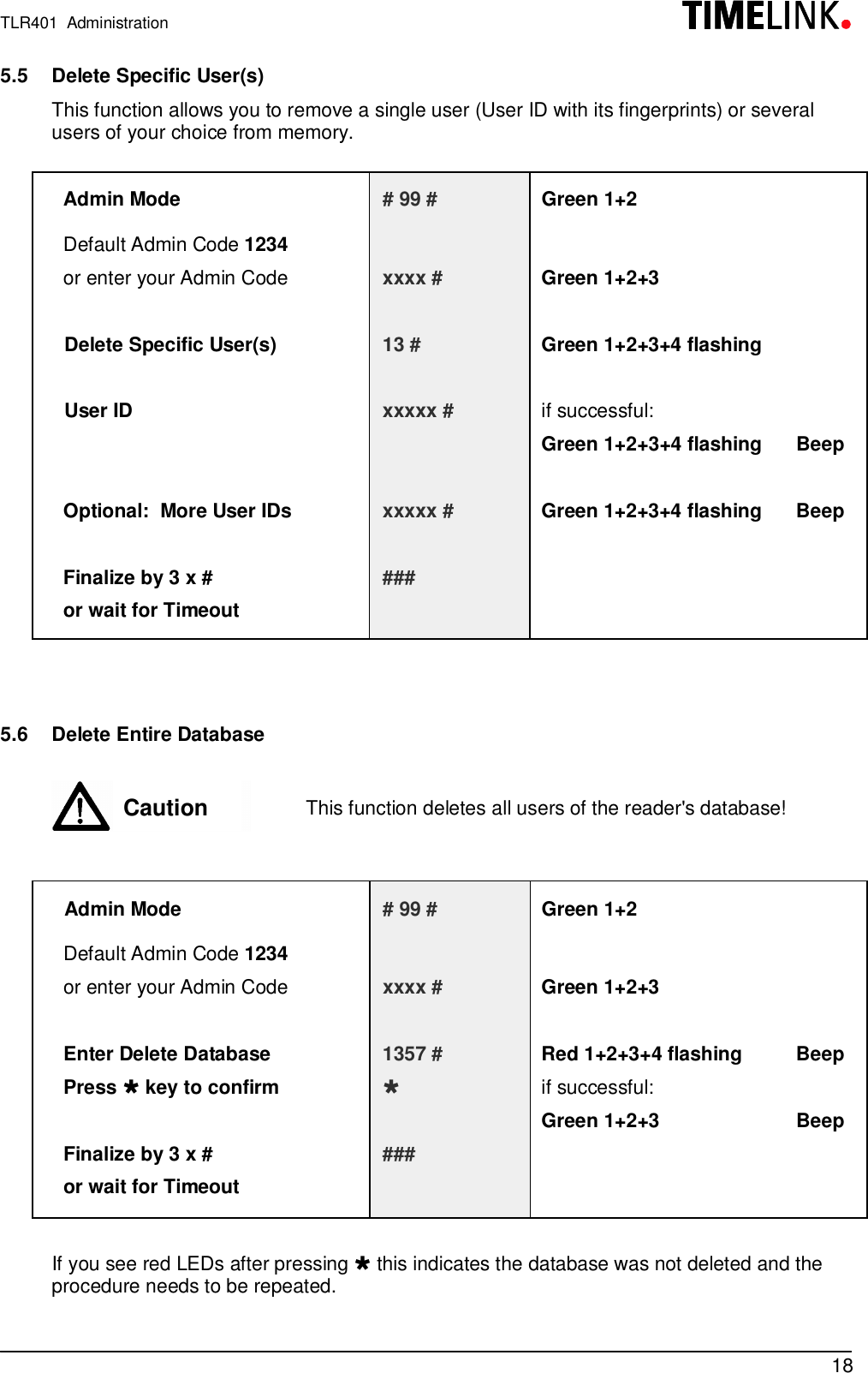
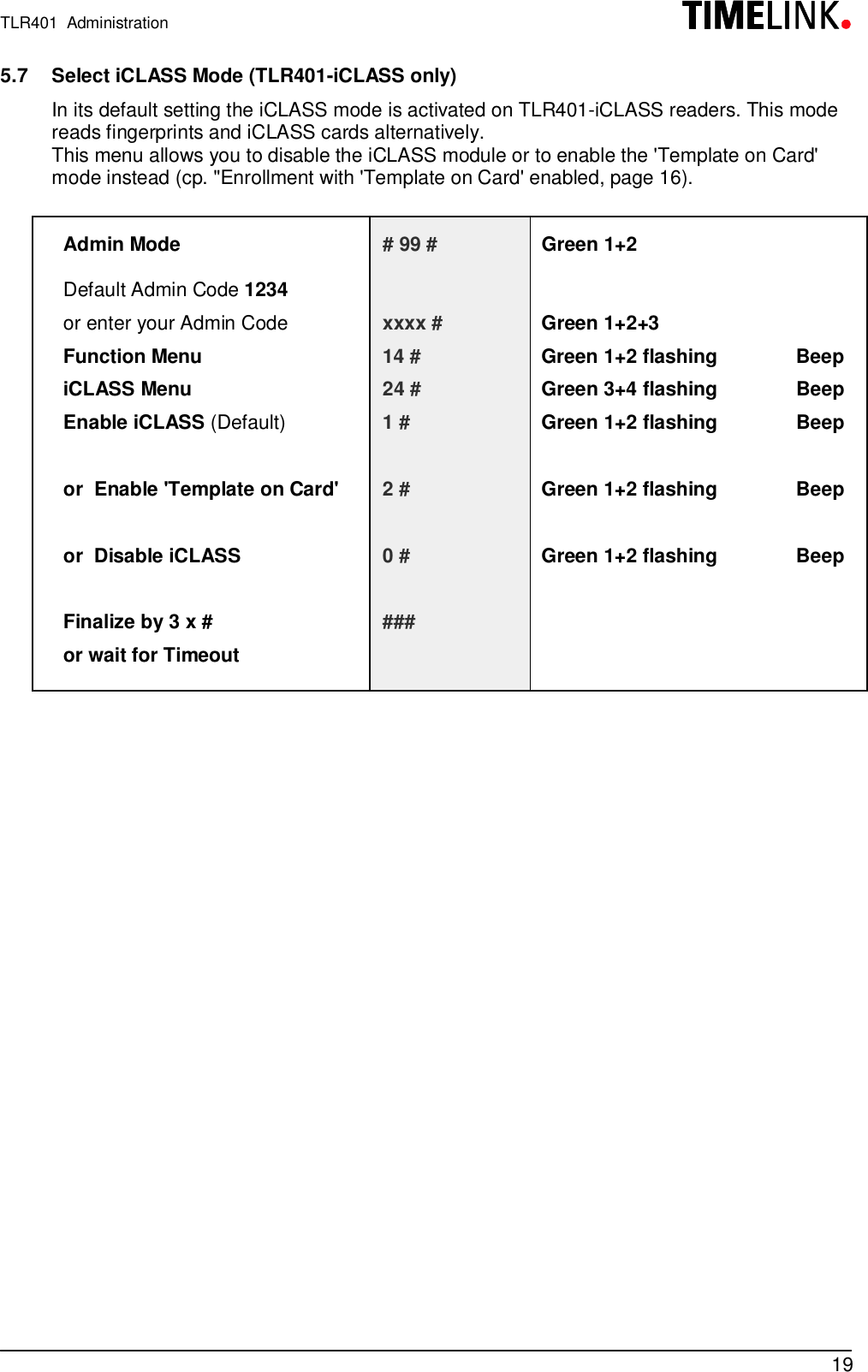
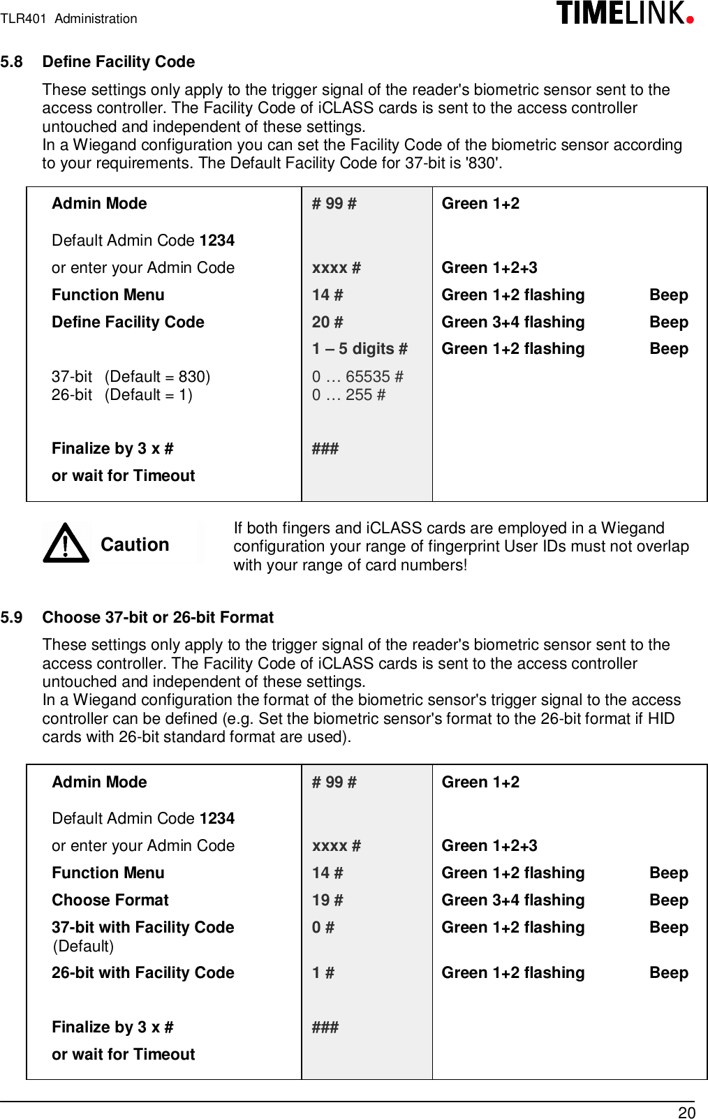
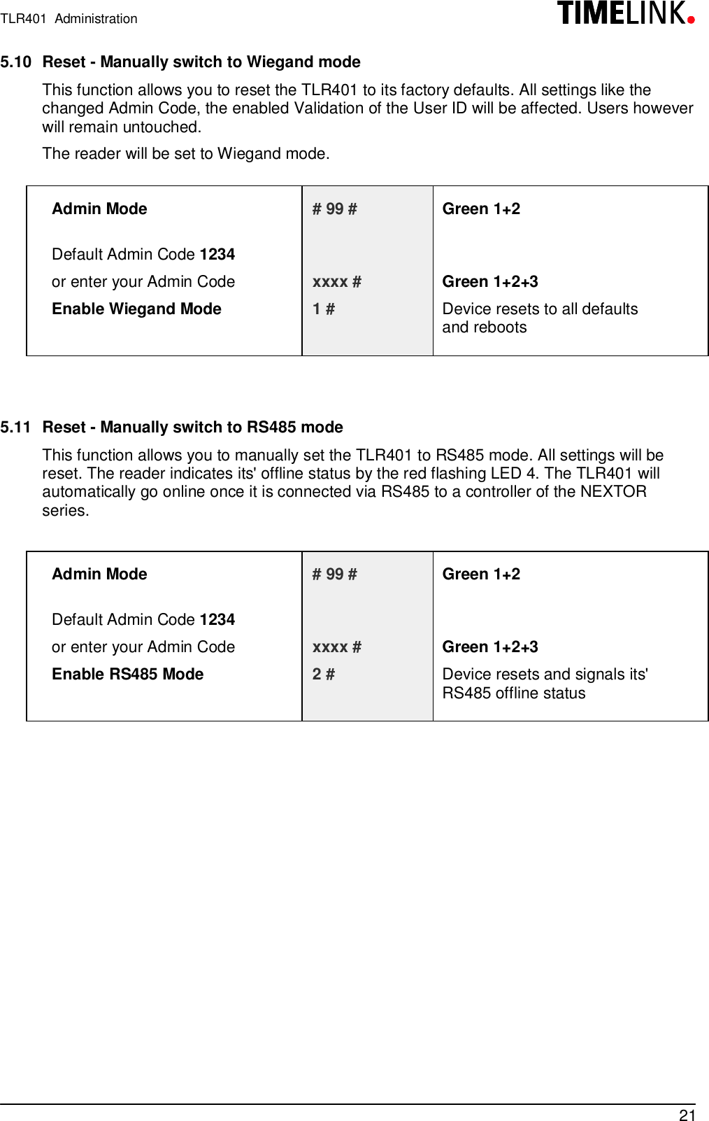
- 1. Users manual
- 2. Information about modifications
Information about modifications