eQ 3 KS300US Wireless Weather Sensor User Manual Manual 200
eQ-3 Limited Wireless Weather Sensor Manual 200
eQ 3 >
Contents
- 1. Manual
- 2. Manual 200
Manual 200

Operating Instructions
Combination Weather Sensor
KS 200US
ELV Electronics Ltd. · Hongkong
2
These operating instructions belong with this product. They contain important information
for putting it into service and operating it. This should be noted also when this product is
passed on to a third party.
Therefore look after these operating instructions for future reference!
A list of contents with the corresponding page numbers can be found in the index on page 4.
1st English edition May 2006
Documentation © 2006 ELV Electronics Limited
All rights reserved. This handbook must not be reproduced in any form, even in excerpts, or
duplicated or processed using electronic, mechanical or chemical procedures without written
permission of the publisher.
This handbook may contain mistakes and printing errors. The information in this handbook is
regularly checked and corrections made in the next issue. We accept no liability for technical
mistakes or printing errors, or their consequences.
All trademarks and patents are acknowledged.
Printed in Hong Kong
Modifications due to technical improvements may be made without prior notification.
00066944 Y2006 V1.0
3
Introduction
Dear Customer,
Thank you for purchasing this product.
The product has been EMC-tested and thus meets the requirements of the valid national
guidelines. See also FCC-Information.
In order to maintain this condition and ensure safe operation, you, as the user, have to observe
this operating manual.
Prior to using the product for the first time, please read the entire operating manual and observe
all operating and safety instructions.
We should already like to point out now the correct order for commissioning the
products. Please also observe the installation and calibration instructions in this
operating manual as well as the information about impairment of radio transmission
between the sensors and base station.
All company names and product descriptions listed herein are the trademarks of the
respective manufacturers. All rights are reserved.
F
4
Table of Contents
Page
1. Intended Use .................................................................................................................... 5
2. Scope of Delivery ............................................................................................................. 6
3. Explanation of Symbols................................................................................................... 6
4. Features and Functions................................................................................................... 7
5. Safety Instructions ........................................................................................................... 7
6. Battery and Accumulator Information ........................................................................... 8
7. Preparation and Start-up ................................................................................................ 9
Start-up of the Multipurpose Sensor ................................................................................. 9
8. Replacing the Battery .................................................................................................... 12
Multipurpose Sensor ....................................................................................................... 12
9. Troubleshooting ............................................................................................................. 13
10. Coverage ........................................................................................................................ 14
11. Maintenance and Cleaning ........................................................................................... 15
a) General ....................................................................................................................... 15
b) Cleaning the Multipurpose Sensor ............................................................................ 15
12. Handling .......................................................................................................................... 16
a) General ....................................................................................................................... 16
b) Multipurpose Sensor .................................................................................................. 16
13. Disposal .......................................................................................................................... 17
a) General ....................................................................................................................... 17
b) Disposal Instructions for Batteries/Accumulators ..................................................... 17
14. Technical Data ................................................................................................................ 18
15. FCC-Information ............................................................................................................ 19

5
1. Intended Use
The combination weather sensor is a high-quality universal weather measuring system which is
able to process a large number of weather data and additional information.
All relevant data are transmitted to an optional base unit.
The forecasts of the basis station are to be considered orientation values. They do not represent
an absolutely accurate prognosis. The manufacturer does not take over any responsibility for
incorrect indications, measured values or weather forecasts and the consequences thereof.
This product is designed for private use and is not suitable for medical purposes or for informing
the public.
The components of this product are not a toy, they contain fragile glass and ceramic parts.
Set up all the components in such a manner that they are out of the reach of children.
The product is operated by batteries. All external sensors transmit their data to the base station
via radio in the range of 433 MHz (coverage up to 100m in the free field).
Use other than that described above will lead to damage to the product.
Please read the complete operating instructions before use. They contain important
information for correct installation, functioning and operation.

6
2. Scope of Delivery
• Multipurpose sensor / combination sensor KS 200US
• Mounting rod for the multipurpose sensor
• Specially shaped aluminium part for installing the mounting rod
• Hose band clip
• Operating instructions
3. Explanation of Symbols
The symbol with the lightening in the triangle is used when your health is at risk, e.g.
through an electric shock
An exclamation mark in a triangle indicates important information in these operating
instructions which must be observed without fail.
The ”hand” symbol can be found when you are to be given tips and information on
operation.
F

7
4. Features and Functions
Multipurpose Sensor
• Radio transmission of:
- wind speed
- temperature
- air humidity
5. Safety Instructions
The warranty will lapse for damage due to non-compliance with these operating
instructions. We shall not be held liable for any consequential damage or loss!
We shall not accept liability for damage to property or personal injury caused
by incorrect handling or non-compliance with the safety instructions. Any claim
to warranty will lapse in such cases.
Dear Customer, the following safety and risk instructions are intended not only for the
protection of your health but also for the protection of the device. Please read through the
following points attentively:
Do not use this product in hospitals or medical institutions. The outdoor sensor does only emit
relatively weak radio signals. These radio signals could, however, lead to malfunctions in life-
supporting systems. The same may possibly apply to other areas.
The multipurpose sensor (and separately/additionally available outdoor sensors) is suitable for
operation in non-protected outdoor areas.
For safety and licensing (CE) reasons, unauthorised conversion of and/or modifications to the
product are not permitted.
Do not leave packaging material lying around carelessly. Plastic foil/bags and polystyrene parts
etc. could become dangerous toys for children.
Handle the product with care. It can be damaged through impact, blows or by being dropped
even from a low height.

8
6. Battery and Accumulator Information
• Batteries/accumulators must be kept out of the reach of children.
• Make sure that the batteries/accumulators are inserted with the correct polarity.
• Do not leave the batteries/accumulators lying around in the open; there is a risk of their being
swallowed by children or domestic animals. If swallowed, immediately contact a doctor.
• Leaking or damaged batteries/accumulators can cause burning if they come into contact with
the skin. For this reason you should use suitable protective gloves.
• Make sure that batteries/accumulators are not short-circuited or thrown into a fire. There is a
risk of explosion!
• Never dismantle batteries/accumulators!
• Batteries may not be recharged. There is a risk of explosion!
• In case of longer periods of non-use (e.g. during storage) remove the inserted batteries/
accumulators to avoid damage by a leaking battery/accumulator.
• Always replace the whole set of batteries/accumulators. Do not mix batteries/accumulators
of different types/manufacturers.
• Never mix batteries with accumulators!
Please note:
The multipurpose sensor can be operated by accumulators. However, due to the
lower voltage of accumulators (accumulator = 1.2 V, battery = 1.5 V) the operating
life can be decreased. Moreover, the radio coverage will be reduced, in rare cases
even malfunctions can be caused.
Therefore, the following rule applies:
If you face any problem during the operation based on accumulators, use batteries
instead of them. We recommend you to operate the weather station, multipurpose
sensor and possibly existing outdoor sensors only with high-quality alkaline batter-
ies.
Please refer to chapter 13 for the environmental-friendly disposal of batteries
and accumulators.
F
9
7. Preparation and Start-up
Please note:
First start up all provided sensors (multipurpose sensor and possibly exist-
ing outdoor sensors) (insert batteries) before starting up the weather station
itself.
If you fail to follow this order of proceeding, it may be that the base station is
not able to identify the provided sensors!
It is principally recommended to test the base station with all its sensors (supplied multipurpose
sensor and possibly existing outdoor sensors) first in a room, before installing the sensors
outside.
The distance between the base station and the sensors must be at least 2m to avoid
interference. Do not place the sensors side by side, but install them throughout the
area (e.g. if you have purchased several additional sensors).
If you find out that one of the sensors is not received after the installation, you can take it for
granted that the radio reception is too weak.
You avoid complex and time-consuming troubleshooting, if you perform this first functional test.
Start-up of the Multipurpose Sensor
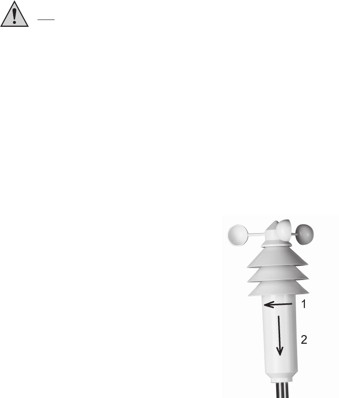
• Open the housing of the multipurpose sensor. First, turn
the lower cover of the housing a little bit towards the arrow
as shown on the right (1) and then pull it carefully
downwards (2).
• There are two options to mount the sensor on a mast:
1. Own installation mast, e.g. purchased in the DIY
superstore
2. Optionally available installation mast matched to the
system (not included in the scope of delivery, is to be
ordered separately)
Fig. 1
F
10
Proceed as follows for mounting:
1. Own individual installation mast
• Screw out the two small screws at the bottom
of the multipurpose sensor a little bit.
• Insert the supplied mounting rod of 25cm from
into the multipurpose sensor the bottom in such
a way that the two holes in the mounting rod
are directly positioned under the screws.
• Then tighten the two screws carefully (screws
are to be screwed into the holes of the mounting
rod).
• The mast required must have a diameter of
between 25mm and 45mm. It can either be a
free mast or a mounting angle, e.g. for a satellite
dish.
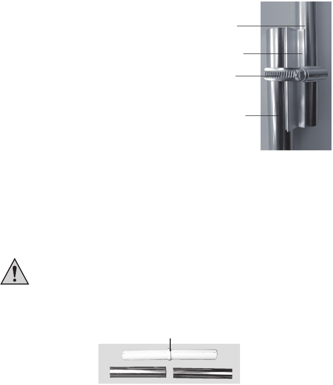
• Position the shaped aluminium part on one
side of this mast/mounting angle and put a
hose band clip over the two parts.
• Set the short mounting rod of the sensor against the other side of the shaped aluminium part
(on the right side in Figure 2 above) and tighten the hose band clip by using a screwdriver.
2. Optionally available installation mast (not included in the scope of delivery)
If you want to drive the rod with the flat tip (serves as an earth tip) into the ground by
means of a hammer, use a suited wooden clump in any case to protect the mast.
Otherwise, the upper end of the rod will be damaged (installation of the sensor mast
will not be possible any longer), guarantee will lapse!
• Assemble the single parts of the sensor mast. Plastic couplers combine the individual rods.
plastic coupler
Fig. 2b
• The flat rod end serves as an earth tip.
supplied
mounting rod
supplied shaped
aluminium part
mounting clip
installation mast
Fig. 2a
11
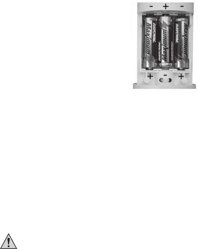
• After the installation of the mast, insert three Mignon-batteries
(LR6/AA) with the correct polarity into the battery compart-
ment. You will find the corresponding image in the battery
compartment (see also figure 3 on the right).
If possible use alkaline batteries.
As already described in chapter 6, accumulators
can be used, too. They, however, can have a nega-
tive influence on the operating life, coverage and
operational safety.
• During the following 5 minutes, the sensor is in the so called
synchronisation mode in which it sends one data package
every 4 seconds.
During this period of time you should insert the batteries
into the base station so that it can identify the sensor.
Fig. 3
• Then close the housing of the multipurpose sensor again, slide the cover upwards and lock it
by turning it to the right (reverse direction than shown in Fig. 1).
• To avoid unnecessary long ways for checking the functions, the final positioning, e.g. in the
garden, should be performed only after a successfully completed functional test as described
at the beginning of this chapter.
The correct location of the multipurpose sensor is decisive for obtaining the most accurate
measuring values.
The temperature sensor inside the housing of the multipurpose sensor is positioned at
the top below the ”umbrellas” in a ventilated area of the housing. Therefore, in direct
sunlight only a slightly higher temperature value will be measured.
Please ensure that the wind sensor at the tip of the multipurpose sensor is not posi-
tioned too close to houses, trees etc., because this could falsify the measured values
of the wind speed.
That’s why, the multipurpose sensor should be set up in a free space, e.g. in the
garden.
• The mast must firmly stick in the soil with the multipurpose sensor being positioned
approximately 2 m above the ground.
When selecting the place of installation, consider the safety for children, pets,
vehicles etc.
If the multipurpose sensor falls down, there is risk of injury or damage to vehicles
or other objects.
Make sure that there are no pipes (e.g. hose pipes for irrigating systems or
similar) at the place where the earth rod is inserted/driven into the ground.
F
F
12
8. Replacing the Battery
The replacement interval varies significantly for batteries and accumulators. High-
quality alkaline batteries are the most efficient ones, whereas accumulators or cheap
zinc-carbon batteries require a more frequent replacement.
Multipurpose Sensor, Outdoor Sensors
If the indication of the individual sensor is not displayed over a period of more than 24 hours,
the batteries are to be replaced as described in chapters 7.
Check, if the failed data transfer is caused by an interfered radio transmission. In this
case an indication will not be given in the display of the base station neither.
Another possible source of the problem could be for example a metal part placed in
the radio line. Such a problem can be detected by the fact that the data transmission
of other sensors being closer positioned also fail. (See chapter 9 on next page.)
F
F

13
9. Troubleshooting
Observe all safety instructions included in these operating instructions!
Problem
No reception
Interference of other
devices by the
outdoor sensors
Problems during
synchronisation
Possible solutions
• The distance between the base station and the outdoor sensors is
too long. Change the place of installation of the outdoor sensors.
• Objects or shielding materials impair the radio reception. Change the
place of installation of the outdoor sensors and the base station.
• The batteries of the outdoor sensors are weak or almost empty. As
a test, insert new batteries into the outdoor sensors.
• Another transmitter at the same or adjacent frequency interferes the
radio signal of the outdoor sensors. This could be wireless phones,
wireless loudspeakers or similar systems.
In most cases, such products are not operated continuously. That
means that the radio reception will be perfect on the following day
and its more difficult to detect the cause of the problem.
If it is possible, set another frequency for these devices. This step
can eliminate the reception problem of the weather station.
• The outdoor sensors emit their data to the base station at intervals
of approximately 3 minutes for the duration of 0.1 second (100ms).
In this short period of time
other devices are possibly interfered. For example, a very short in-
terfering signal can be heard in a wireless phone every 3 minutes.
• When the batteries are inserted into the outdoor sensors and the base
station (keep strictly to this order of proceeding!!), these devices are
in the synchronisation mode. Here, a data telegram is emitted every
4 seconds. This accelerates the detection and registration process
of the outdoor sensors at the base station.
To force a new synchronisation, take the batteries out of the base
station and the outdoor sensors. Afterwards, wait at least 50 seconds
before inserting the batteries again into the outdoor sensors and
finally in the base station (this sequence is to be observed in any
case, first insert the batteries into all the existing outdoor sensors
and only then insert the batteries into the base station).
However, all the data/values saved in the base station (e.g. minimum
values, maximum values, but also dates and times) will be lost
then.
• Before installing the outdoor sensors for example in your garden,
carry out a functional test as described at the beginning of chapter 7.

14
10. Coverage
The coverage of the transmission of the radio signals to the base station can reach up to 100m
under optimal conditions. This is also often designated as ”free-field coverage”.
This ideal arrangement (e.g. base station and outdoor sensor on a plane, even meadow
without trees, houses etc.), however, is never reality.
Normally, the base station is installed inside the house, the multipurpose sensor in the garden
and further outdoor sensors are positioned in outbuildings (e.g. in a aviary) or in the garage.
The coverage can be considerably limited by:
• walls, reinforced concrete ceilings
• coated/vapour-deposited insulating glass panes
• vehicles
• trees, brushes, earth, rocks
• the proximity to metallic & conductive objects (e.g. heating elements)
• the proximity to the human body
• broad-band interference, e.g. in residence areas (DECT telephones, mobile phones, wireless
loudspeakers, other radio weather stations, baby phones etc.)
• the proximity to electric motors, transformers, power supply units, computers
• the proximity to improperly shielded or uncovered operating computers or other electric
appliances
However, a guarantee for a specific coverage is not possible as the local circumstances
are different for different places of installation.
If the base station does not receive data from the multipurpose sensor or from pos-
sibly additional other sensors (despite new batteries), reduce the distance between
the outdoor sensors and the base station, change the place of installation.
F
FF

15
11. Maintenance and Cleaning
a) General
Check the technical safety of the weather station, such as damage to the housing, at regular
intervals.
When it can be assumed that a safe operation is no longer possible, the product must be put
out of service and precautions taken to ensure that it is not used unintentionally. Remove the
batteries.
It must be assumed that safe operation is not possible any longer, if
• the station is visibly damaged,
• the device does not operate any longer and
• it has been stored for long periods under unfavourable conditions or
• it has been subject to considerable stress in transit.
The safety instructions below must be observed before the weather station is cleaned or
maintained:
Before cleaning, servicing or repair works, the batteries must be removed.
None of the components inside the station is to be maintained by the user. The hous-
ing must not be opened.
Repair work must always be carried out by qualified experts familiar with the hazards
involved and with the relevant regulations.
b) Cleaning the Multipurpose Sensor
After a longer period of operation in the open, dust can deposit at the plastic surface of the
outdoor sensors. It can be removed rapidly with a cloth slightly moistened in water.
Never use a garden hose to clean the outdoor sensors, because they are only pro-
tected against rain coming from the sky above but not against jets of water coming
from the sides or below.

16
12. Handling
Observe all safety instructions included in these operating instructions!
a) General
The product may not be opened or disassembled (apart from the battery replacement described
in these operating instructions).
None of the components inside the product is to be maintained by the user. Moreover, the licence
(CE) and warranty will lapse in such cases.
Do not drop the product, it will be damaged even if it falls down from a low height.
b) Multipurpose Sensor
Although the multipurpose sensor is protected against rain coming from above, it is not protected
against water from the sides or below. Therefore, never splash the station, e.g. by means of a
garden hose or another irrigation system.
Select such a place of installation that children can not tilt the multipurpose sensor. Do not set
it up in the proximity of vehicles, glass doors/windows or similar objects!

17
13. Disposal
a) General
Once the product becomes unusable, dispose of it in accordance with the relevant statutory
regulations.
b) Disposal Instructions for Battery/Accumulators
You, as the ultimate consumer, are required by law (Battery Ordinance) to return all spent
batteries/accumulators. Disposing of spent batteries/accumulators in the household waste
is prohibited!
Batteries/accumulators containing hazardous substances are marked by the opposite
symbols. These symbols also indicate that it is prohibited to dispose of these batteries
in the household waste.
The heavy metals concerned are: Cd=cadmium, Hg=mercury, Pb=lead (the designa-
tion is written on the accumulator e.g. under the rubbish can symbols depicted at
the left).
You can hand in your used batteries/accumulators at the official collection points of
your community at no cost, at our outlets or everywhere where batteries/accumula-
tors are sold.
You thus fulfil your statutory obligations and contribute to the protection of the environment.
18
14. Technical Data
Measurement interval of the outdoor sensors:...approx. 3 minutes
Measurement interval of the indoor sensors: ..... approx. 10 minutes
Transmitting frequency: ...................................... 433.92 MHz
Coverage in the open field: ................................ max. 100m (Observe chapter 10!)
Outdoor temperature range : .............................. -29.9°C to +79.9°C
Resolution: ......................................................... 0.1°C
Accuracy: ........................................................... ±0.8°C
Measurement range of relative air humidity
(indoor/outdoor): ................................................. 1% - 99 %
Resolution: ......................................................... 1%
Accuracy: ........................................................... ±5% rH (30–70% rH)
Wind speed: ....................................................... 0 to 200km/h
Resolution: ......................................................... up to100km/h 0.1km/h; above 100km/h: 1km/h
Voltage supply:.................................................. 3 x 1.5 V Mignon-batteries (LR6/AA),
(alkaline type recommended)
19
15. FCC Information
FCC ID: RNT-KS300US
Changes or modifications not expressly approved in writing by ELV Electronics Limited may void
the user’s authority to operate the equipment.
NOTE: This equipment has been tested and found to comply with the limits for a Class B digital
device, pursuant to Part 15 of the FCC Rules. These limits are designed to provide reasonable
protection against harmful interference in a residential installation. This equipment generates,
uses and can radiate radio frequency energy and, if not installed and used in accordance with
the instructions, may cause harmful interference to radio communications. However, there is
no guarantee that interference will not occur in a particular installation. If this equipment does
cause harmful interference to radio or television reception, which can be determined by turning
the equipment off and on, the user is encouraged to try to correct the interference by one or
more of the following measures:
- Reorient or relocate the receiving antenna.
- Increase the separation between the equipment and receiver.
- Connect the equipment into an outlet on a circuit different from that to which the receiver is
connected.
- Consult the dealer or an experienced radio/TV technician for help.
The internal antenna used for this mobile transmitter must provide a separation distance of at
least 20 cm from all persons and must not be co-located or operating in conjunction with any
other antenna or transmitter.
This device complies with Part 15 of the FCC Rules. Operation is subject to the following two
conditions:
(1) this device may not cause harmful interference, and
(2) this device must accept any interference received, including interference that may cause
undesired operation.

20
ELV Electronics Ltd. · Hongkong