eQ 3 KS300US Wireless Weather Sensor User Manual Manual
eQ-3 Limited Wireless Weather Sensor Manual
eQ 3 >
Contents
- 1. Manual
- 2. Manual 200
Manual
1
Operating Instructions
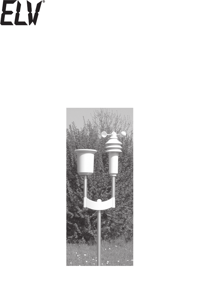
Combination Weather Sensor
KS 300-2US
ELV Electronics Ltd. · Hongkong
2
1st English edition May 2006
Documentation © 2006 ELV Electronics Limited
All rights reserved. This handbook must not be reproduced in any form, even in excerpts, or
duplicated or processed using electronic, mechanical or chemical procedures without written
permission of the publisher.
This handbook may contain mistakes and printing errors. The information in this handbook is
regularly checked and corrections made in the next issue. We accept no liability for technical
mistakes or printing errors, or their consequences.
All trademarks and patents are acknowledged.
Printed in Hong Kong
Modifications due to technical improvements may be made without prior notification.
00066932 Y2006 V1.0
These operating instructions belong with this product. They contain important information
for putting it into service and operating it. This should be noted also when this product is
passed on to a third party.
Therefore look after these operating instructions for future reference!
A list of contents with the corresponding page numbers can be found in the index on page 4.
3
Introduction
Dear Customer,
Thank you for purchasing this product.
The product has been EMC-tested and thus meets the requirements of the valid national
guidelines. See also FCC-Information.
In order to maintain this condition and ensure safe operation, you, as the user, have to observe
this operating manual.
Prior to using the product for the first time, please read the entire operating manual and observe
all operating and safety instructions.
We should already like to point out now the correct order for commissioning the
products. Please also observe the installation and calibration instructions in this
operating manual as well as the information about impairment of radio transmission
between the sensors and base station.
All company names and product descriptions listed herein are the trademarks of the re-
spective manufacturers. All rights are reserved.
F
4
Table of Contents
Page
1. Intended use ..........................................................................................................................5
2. Scope of delivery ...................................................................................................................6
3. Terminology ...........................................................................................................................6
4. Features and functions ..........................................................................................................6
5. Safety instructions .................................................................................................................6
6. Battery and environment instructions ....................................................................................7
7. Preparation for operation, commissioning ............................................................................7
8. Changing battery ...................................................................................................................9
9. Troubleshooting ...................................................................................................................10
10. Range ..................................................................................................................................11
11. Maintenance and cleaning ...................................................................................................12
a) General ............................................................................................................................12
b) Cleaning combination sensor ..........................................................................................12
12. Handling ..............................................................................................................................14
a) General ............................................................................................................................14
b) Combination sensor ........................................................................................................14
13. Disposal ...............................................................................................................................15
a) General ............................................................................................................................15
b) Disposing of batteries and accumulators ........................................................................15
14. Technical data ......................................................................................................................16
15. FCC-Information ..................................................................................................................17

5
1. Intended use
The combination weather sensor is a high-quality universal weather measuring system which
processes a large quantity of weather data and additional information.
All relevant data are transmitted to an optional base unit.
The forecasts of the base station serve only the purpose of orientation. They do not represent
an absolutely true forecast. The manufacturer does not assume any responsibility for incorrect
displays, measuring values or weather forecasts or any consequences which may result from
these.
The product is intended for private use. It is not suited for medical purposes or public information.
The components of this product are not toys. Install all components in such a way that children
have no access to them.
The product is battery-operated. All external sensors transmit their data per radio to the base
station (433 MHz, range up to 100 m in open space, see chapter 10 on page 11).
Any other use than that described above may lead to damage to the product or to
other danger.
Read the complete operating manual carefully. It contains much important information
about the installation and operation.

6
2. Scope of delivery
• Combination sensor KS 300-2US
• Metal rods/pegs for the combination sensors
• Operating manual
3. Terminology
An exclamation mark in a triangle indicates important instructions in the operating
manual which must be observed under all circumstances.
You will see the „hand” symbol for special tips and instructions concerning operation.
4. Features and functions
• Radio transmission of:
- rain quantity
- immediate rain detection
- wind velocity
- temperature
- humidity
5. Safety instructions
Damage caused by non-observance of this operating manual can lead to forfeitu-
re of the warranty! We shall not assume any liability for subsequent damage!
We shall not assume any liability for damage to items or persons caused by
improper handling or non-observance of the safety instructions! In such cases,
any guarantee claims shall become null and void .
Dear Customer, the following safety and hazard notices not only serve the protection
of your health but also the protection of the appliance. Please read the following points
carefully!
Do not use this product in hospitals or medical institutions. Although the outdoor sensor only
emits relatively weak radio signals, these may cause interference to life-support systems. The
same can also apply in other areas.
If used correctly, the rain/wind detector is suited on the other hand to unprotected outdoor
locations.
For safety and licensing reasons (CE), it is not permitted to convert or modify the product.
F

7
Do not leave the packaging material lying around. Plastic foil and bags, polystyrene parts etc.
are dangerous toys in the hands of children.
Handle the product with care! Blows or impact, or dropping it even from a small height will
damage it.
6. Battery and environment instructions
• Batteries do not belong in the hands of children.
• Observe the right polarity when inserting the batteries/accumulators.
• Do not leave batteries lying around. Pets or small children may swallow them. If they are
swallowed, contact a doctor immediately.
• Leaking or damaged batteries/accumulators may lead to injury to the skin. For this reason,
use suitable protective gloves when changing them.
• Make sure that batteries or accumulators are not thrown into the fire or short-circuited. There
is a likelihood of explosion!
• Never dismantle batteries/accumulators!
• Do not recharge normal batteries. There is a risk of explosion!
• If the product is not used for longer periods of time (e.g. in case of storage), please remove
the inserted batteries/accumulators in order to prevent damage caused by leaking batteries/
accumulators.
7. Preparation for operation, commissioning
Please observe:
First of all, put all available outdoor sensors into operation (insert batteries)
and then the base station itself.
If you proceed in the opposite order, it could occur that the base station does
not detect all the existing outdoor sensors.
We always recommend you to first of all try out the base station with all outdoor sensors (in as
much as you have purchased additional outdoor sensors besides the supplied combination sensor)
in a room before installing the outdoor sensors in the open air. However, the distance between
the base station and the outdoor sensors should be at least 2 m in order to avoid interference.
If you notice that one outdoor sensor is out of range after installation, you can assume that radio
reception is not sufficient (and that there is no defect in the outdoor sensor).
This initial function test will save extensive and time-consuming error searches afterwards.
8
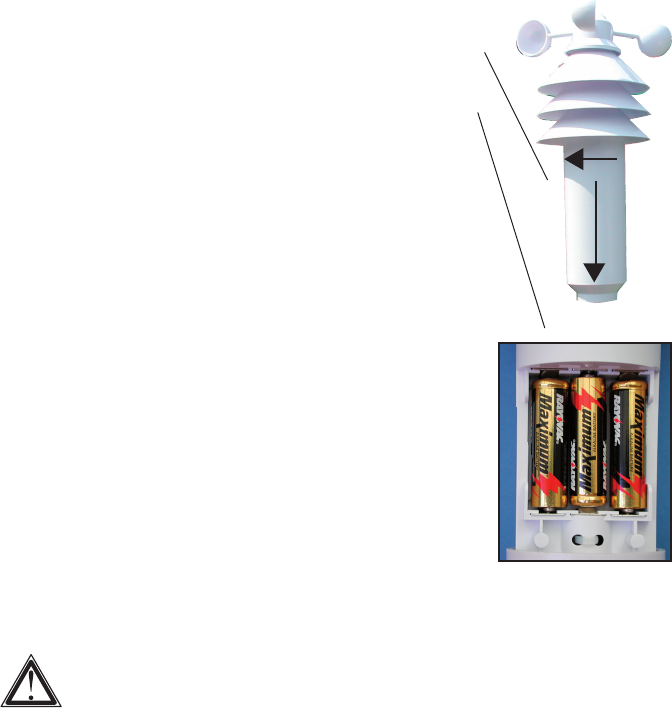
Commissioning the combination sensor
• Open the casing of the sensor. First of all, turn the lower casing cover slightly in the direction
of the arrow (1) as shown below and then carefully lower the casing cover.
• Now insert three batteries (LR6/mignon/AA) with the correct polarity
into the battery compartment (see illustration below on the right).
Use preferably alkaline batteries.
Accumulators can also be used but these reduce will
reduce the range due to the lower voltage / capacity as
well as their operating life!
For the first 5 minutes the combination sensor is in a test mode and
sends its data-telegrams in an intervall of approx. 3 seconds. After
completion of the test mode the normal transmission interval of ap-
prox. 155 seconds is activated.
It must be guaranteed that the combination sensor has already left
its test mode when the synchronisation mode of the base station
is terminated, otherwise a normal reception isn’t possible.
• Close the sensor casing, slide the cover to the top and lock it
again.
• Assemble the installation base.
As already explained above, you should first of all install the sensors
in the garden etc. after a successful initial function test.
It may be difficult to find a favourable place for the combination sen-
sor as this should stand preferably in the shade in order to measure
the correct temperature. On the other hand, it is also necessary to
consider the functions of the wind and rain sensor.
Closeness to buildings, trees, etc. may impair the measuring values
of the wind and rain sensor.
Once you have found a favourable location, insert the earth peg deep into the ground in order to
ensure the stability of the combination sensor.
When selecting the installation site, take the safety of children, pets, vehicles,
etc into consideration.
Any risk of the combination sensor’s falling poses the risk of injury or danger
of damaging vehicles or other objects.
You can also use a hammer to insert the earth peg into the ground. However,
use a suitable piece of wood or similar in order not to damage the top end of
the pipe as this makes it impossible to connect the other pieces of pipe (loss
of warranty)!
Make sure that there are no pipes or similar installed in the area where you wish
to insert the peg into the ground (e.g. hoses for irrigation systems or similar).
++
+
–
– –
below
1
2
F
9
8. Changing battery
Depending on which batteries or accumulators you use, the replacement interval can
be very different. High-quality alkaline batteries keep the longest, accumulators for
cheap zinc-carbon batteries require more frequent changing.
Combination sensor, outdoor sensor
When the display of the sensor concerned fails for more than 24 hours, the batteries are to be
replaced with new ones as described in section 7.
Check as whether there is possibly some disturbance in the radio transmission which
is the cause for the failure of the data transmission. In this case also, there will be no
indication in the display of the base station.
The cause could be, for example, a metal object in the radio path (e.g., a parked
vehicle).
F
F

10
9. Troubleshooting
Observe the safety instructions contained in these operating instructions
Problem Remedy
No reception • The distance between the base station and outdoor sensors is
too great.
Alter the position of the outdoor sensors.
• Objects or shielding materials are obstructing the radio reception.
Alter the position of the outdoor sensors and the base station.
• The batteries of the outdoor sensors are too weak or flat.
Insert new batteries into the sensors as an attempt.
• Another transmitter on the same or neighbouring frequencies is
disturbing the radio signal of the outdoor sensors. This can be, for
example, radio headphones, radio loudspeakers or similar devices.
Such products are not usually operated constantly; the radio
reception can, for example, be perfect the next day; this makes
the search for the cause more difficult.
If possible, set another frequency on the instruments which can
eliminate the reception problems of the weather station.
Disturbance of • The outdoor sensors transmit their data to the base station approx.
other instruments every 3 minutes for a period of 0.1 (100ms) seconds. In this short
through the outdoor period, disturbances in other devices are also possible.
sensors For example, a very short disturbance signal can be audible from
a radio head phone every 3 minutes.
Problems with the • When inserting the batteries into the outdoor sensors and the base
synchronisation station (observe this order exactly!), these devices are in
synchronisation mode. A data telegram is transmitted here every
4 seconds which accelerates the recognition and registration of
the outdoor sensors at the base station.
To enforce new synchronisation, remove the batteries from the
base station and outdoor sensors. After that, wait at least 60
seconds before you insert the batteries into the outdoor sensors
again and, lastly, into the base station (observe this order without
fail – first of all insert the batteries into all existing outdoor sensors,
only then into the base station.
In doing so, however, all values/data which the base station has
stored (e.g. minimum values, maximum values and date/time etc.),
are lost.
• Before you position the outdoor sensors, for example in your
garden, carry out a function test as described at the beginning of
section 7.
11
10. Range
The transmission range of the radio signals to the base station is 100 m under optimum condi-
tions. This is often described as the „free field range”.
This ideal arrangement (e.g. base station and outdoor sensor on a smooth, level field
without trees, houses etc.) is, however, never found in practice.
Normally, the base station is set up in the house, the combination in the garden and further
outdoor sensors, for example in ancillary buildings (e.g. in an aviary) or garage.
The range can be reduced considerably partly through:
• walls, reinforced steel ceilings
• coated/vapoured insulation glass panes
• vehicles
• trees, bushes, earth, rocks
• closeness to metal & conductive objects (e.g. radiators)
• closeness to the human body
• broadband disturbances, e.g. in residential area (DECT telephones, mobile telephones, radio
head-phones, radio loudspeakers, other radio weather stations, baby phones etc.)
• closeness to electric motors. Transformers, network parts pr computers
• closeness to poorly shielded or openly operated computers or other electrical devices
As the local circumstances are different at every place of set-up, a certain range
cannot be guaranteed.
If the base station is receiving no data from the combination sensor or any additionally
existing outdoor sensors (in spite of new batteries), reduce the distance between the
outdoor sensors and the base station, change the place of set-up .
Observe section 7 and 9 of these operating instructions.
F
F

12
11. Maintenance and cleaning
a) General
Check the technical safety of the product regularly, e.g. damage to the housing.
It can be assumed that operation is no longer ensured without risk if
• the device shows visible damage
• the device is no longer functional
• after longer periods of storage under unfavourable conditions or
• after heavy transport stress
Before cleaning or servicing the device, observe the following safety instructions without
fail:
Remove the batteries before cleaning, servicing or carrying out repair work.
There are no parts in the interior requiring servicing; the device may not be opened.
Repairs may only be carried out by a specialist who is familiar with the associated
hazards and relevant regulations for the device.
b) Cleaning combination sensor
After a longer period of operation in the open air, dirt can gather on the plastic surface of the
outdoor sensors.
This can be removed very readily with a soft cloth which has been moistened with water.
Never spray the outdoor sensors with, for example, a garden hose as the outdoor
sensors are only protected against rain from above and not against water jets from
the side or from below.
The rain gauge should be monitored from time to time.
Depending on the location, leaves, particles of dirt carried by the wind, small twigs and similar
can enter the cone collector of the rain gauge. Large parts can clog the flow-through!
Sand can also collect in the count rocker which will affect the measuring result negatively as it
increases.
For this reason, the rain gauge should be cleaned at least once a year.
Proceed as follows:
• open the lower part of the rain gauge. To do this, turn the lower part approx. 1 cm to the left
until you can let the metal nips slide downwards.
• remove the upper cone collector by turning it first of all a small distance to the right; then lift
it off to the top.
• the rainfall sensor (the plastic part with the two brass pins and cable) can now be removed.
F
13
Make a note of the orientation; the connection cable of the rainfall sensor can be
found at one side.
• Remove the count rocker.
Make a note of the orientation; there is a small magnet at one side of the count
rocker.
• Now clean the components of the rain gauge. Think also of the drain hole in the plastic lower
part of the rain gauge which you have pushed downwards at the metal pipe.
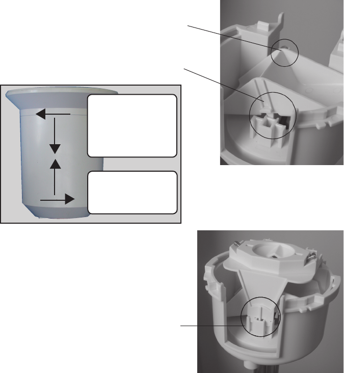
• To reassemble, place the count rocker first of all in the holder.
For this, the magnet of the count rocker has to
belocated on the side which points to the cable.
The two lower trapezoid pins have to be inserted
into the lower part of the holder correctly.
Only in this manner is it guaranteed that the count
rocker can be moved easily.
F
F
F
1 - Vollmond
2 - Zunehmend
3 - Neumond
4 - Abnehmend
Remove cover:
- turn left
- pull down cover
- lift off upper cone
Mount cover:
- snap in cover
- turn right
• Insert the rainfall sensor into its holder. It will hold
the count rocker firmly automatically.
Only one orientation is correct; the cable
of the rainfall sensor and the magnet of the
count rocker have to be on the same side;
the plastic nib on the other side has to be
inserted precisely into the holder, look at
the circle in the picture on the right.
F

14
• Place the cone collector from the top onto the sensor carrier and snap it in by turning it to the
left.
• Push the lower part of the rain gauge housing upwards and lock it by turning it to the right
until it snaps in.
The drain holes in the lower part of the housing have to point to the outside so that
the water does not run on to the metal stands.
12. Handling
Observe all the safety precautions in these operating instructions!
a) General
The product may not be opened or taken apart (except for the work described in these operating
instructions, e.g. change of battery or cleaning the rain gauge).
There are no parts to be maintained by the user in the inside of the product.
The product will be damaged even if dropped from a low height.
b) Combination sensor
Although the combination sensor is protected against rain from above, this is not the case,
however, from the side or from below. Therefore, avoid any direct spraying, for example, through
a garden hose or another watering system.
Select the place of set-up so that children cannot tip the combination sensor over; do not place
the combination sensor in the proximity of vehicles, glass doors, windows or similar!
F
15
13. Disposal
a) General
Dispose of the unusable product according to valid legal regulations
b) Disposing of used batteries and accumulators
You, as ultimate consumer, are required by law (battery regulations) to return all used batteries.
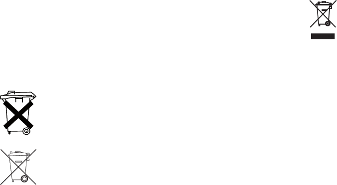
Disposing of used batteries with domestic waste is prohibited!
Batteries / accumulators containing toxins are marked by appropriate symbols which
refer to the prohibition of disposal with domestic waste.
The designations for the decisive heavy metals are: Cd = cadmium, Hg = mercury,
Pb = lead (The designation can be found on the battery under the dustbin symbol
illustrated on the left).
You may return used batteries/accumulators free of charge to collecting stations, our
outlets or anywhere else where batteries/accumulators are sold.
By doing so, you fulfil the legal requirements and contribute to the conservation of our environment.
16
14. Technical data
Measuring interval of the outdoor sensors: ......................................................approx. 3 minutes
Measuring interval of the indoor sensor: ........................................................approx. 10 minutes
Transmission frequency: ............................................................................................ 433.92 MHz
Range in the free field:...................................................................... (please observe Section 10)
Temperature range outdoors: .........................................................................-19.9°C to +79.9°C
Dissolution: ...........................................................................................................................0.1°C
Exactitude: ........................................................................................................±0.8°C (10–40°C)
Measurement range rel. humidity: ............................................................................... 0% - 99 %
Dissolution: .............................................................................................................................. 1%
Exactitude: ..................................................................................................±5% rH (30–70% rH)
Rain quantity display: ................................................................................................ 0 to 999mm
Dissolution: .................................................................................................................... < 0.3 mm
Wind velocity: .............................................................................................................. 0-200km/h
Dissolution: .........................................................up to 100km/h: 0.1km/h; over 100km/h: 1km/h
Voltage supply: ................................................................................... 3 x 1.5 V LR6, mignon, AA
17
15. FCC Information
FCC ID: RNT-KS300US
Changes or modifications not expressly approved in writing by ELV Electronics Limited may void
the user’s authority to operate the equipment.
NOTE: This equipment has been tested and found to comply with the limits for a Class B digital
device, pursuant to Part 15 of the FCC Rules. These limits are designed to provide reasonable
protection against harmful interference in a residential installation. This equipment generates,
uses and can radiate radio frequency energy and, if not installed and used in accordance with
the instructions, may cause harmful interference to radio communications. However, there is
no guarantee that interference will not occur in a particular installation. If this equipment does
cause harmful interference to radio or television reception, which can be determined by turning
the equipment off and on, the user is encouraged to try to correct the interference by one or
more of the following measures:
- Reorient or relocate the receiving antenna.
- Increase the separation between the equipment and receiver.
- Connect the equipment into an outlet on a circuit different from that to which the receiver is
connected.
- Consult the dealer or an experienced radio/TV technician for help.
The internal antenna used for this mobile transmitter must provide a separation distance of at
least 20 cm from all persons and must not be co-located or operating in conjunction with any
other antenna or transmitter.
This device complies with Part 15 of the FCC Rules. Operation is subject to the following two
conditions:
(1) this device may not cause harmful interference, and
(2) this device must accept any interference received, including interference that may cause
undesired operation.
18
19

20
ELV Electronics Ltd. · Hongkong