eQ 3 TRX916 RF Tranceiver Module User Manual eQ 3 TRX916 UserMan
eQ-3 Limited RF Tranceiver Module eQ 3 TRX916 UserMan
eQ 3 >
Manual

UHF Transceiver Module TRX916
User Manual

UHF Transceiver Module TRX916 User Manual V 1.0
eQ-3 Limited Page : 2 of 12
Table Of Contents
1 KEY FEATURES .................................................................................................................................. 4
2 APPLICATIONS FOR THE MODULE.............................................................................................. 4
3 DESCRIPTION OF THE MODULE................................................................................................... 4
4 HISTORY FOR THE DOCUMENT.................................................................................................... 5
5 TERMINAL LAYOUT ......................................................................................................................... 5
5.1 PIN ASSIGNMENT ............................................................................................................................ 5
6 BLOCK DIAGRAM .............................................................................................................................. 6
7 ABSOLUTE MAXIMUM RATINGS .................................................................................................. 6
8 OPERATING CONDITIONS............................................................................................................... 7
9 RF RECEIVE SECTION...................................................................................................................... 7
10 RF TRANSMIT SECTION................................................................................................................... 7
11 DC CHARACTERISTICS.................................................................................................................... 8
12 MODULE DIMENSION ....................................................................................................................... 8
13 FOOTPRINT.......................................................................................................................................... 9
14 LABELING DRAWING ....................................................................................................................... 9
15 SOFTWARE / REGISTER SETTINGS ............................................................................................ 10
16 NOTES OF DESIGN ........................................................................................................................... 10
17 FCC INFORMATION......................................................................................................................... 10
17.1 FCC ID......................................................................................................................................... 10
17.2 FCC NOTICE ................................................................................................................................. 11
17.3 INFORMATION TO THE USER.......................................................................................................... 11
17.4 LABELING REQUIREMENTS............................................................................................................ 12
17.5 RF EXPOSURE ............................................................................................................................... 12
17.6 PERFORMANCE INFORMATION....................................................................................................... 12
18 ORDERING INFORMATION........................................................................................................... 12
19 DISCLAIMER ..................................................................................................................................... 12

UHF Transceiver Module TRX916 User Manual V 1.0
eQ-3 Limited Page : 3 of 12
1st English edition October 2006
Documentation © 2006 eQ-3 Limited, Hong Kong
All rights reserved. This handbook must not be reproduced in any form, even in excerpts,
or duplicated or processed using electronic, mechanical or chemical procedures without
written permission of the publisher.
This handbook may contain mistakes and printing errors. The information in this handbook
is regularly checked and corrections made in the next issue. We accept no liability for
technical mistakes or printing errors, or their consequences.
All trademarks and patents are acknowledged.
Printed in Hong Kong
Modifications due to technical improvements may be made without prior notification.
00073928 Y 2006 V 1.0

UHF Transceiver Module TRX916 User Manual V 1.0
eQ-3 Limited Page : 4 of 12
1 Key Features
• Supply voltage 1.8 V – 3.6 V
• Frequency 916.500 MHz
• Data rate 10 kbit/s
• High sensitivity -104 dBm
• Output power (EIRP) 94 dBuV/m @ 3 m or –1 dBm (EIRP)
• FSK modulation
• Integral λ/4 monopole
• Separate 64-byte RX and TX data FIFOs
• Efficient SPI interface: All register can be programmed with one “burst” transfer
2 Applications For The Module
• Consumer Electronics
• RKE Two-way Remote Keyless Entry
• Low power telemetry
• Home and building automation
• Wireless alarm and security systems
• Wireless sensor networks
3 Description Of The Module
The transceiver module eQ-3 TRX916 contains a true single chip UHF transceiver
designed for very low power wireless applications.
The transceiver module operates within the frequency band 902 MHz to 928 MHz
according to FCC Part 15, Section 15.249. The transmission and receive frequency is set to
916.5 MHz. FSK modulation is done with 19 kHz deviation.
The transceiver module TRX916 provides extensive hardware support for packet handling,
data buffering, burst transmission link quality and wake on radio.
The main operation parameters and the 64-byte transmit/receive FIFOs of the transceiver
module can be controlled via an SPI interface. A system consists of two transceiver
modules integrated in an appropriate terminal equipment, which can be used in each case
as transmitters and/or receivers.
UHF Transceiver Module TRX916 User Manual V 1.0
eQ-3 Limited Page : 5 of 12
4 History For The Document
Revision Date Modification / Remarks
V 1.0 October 6, 2006
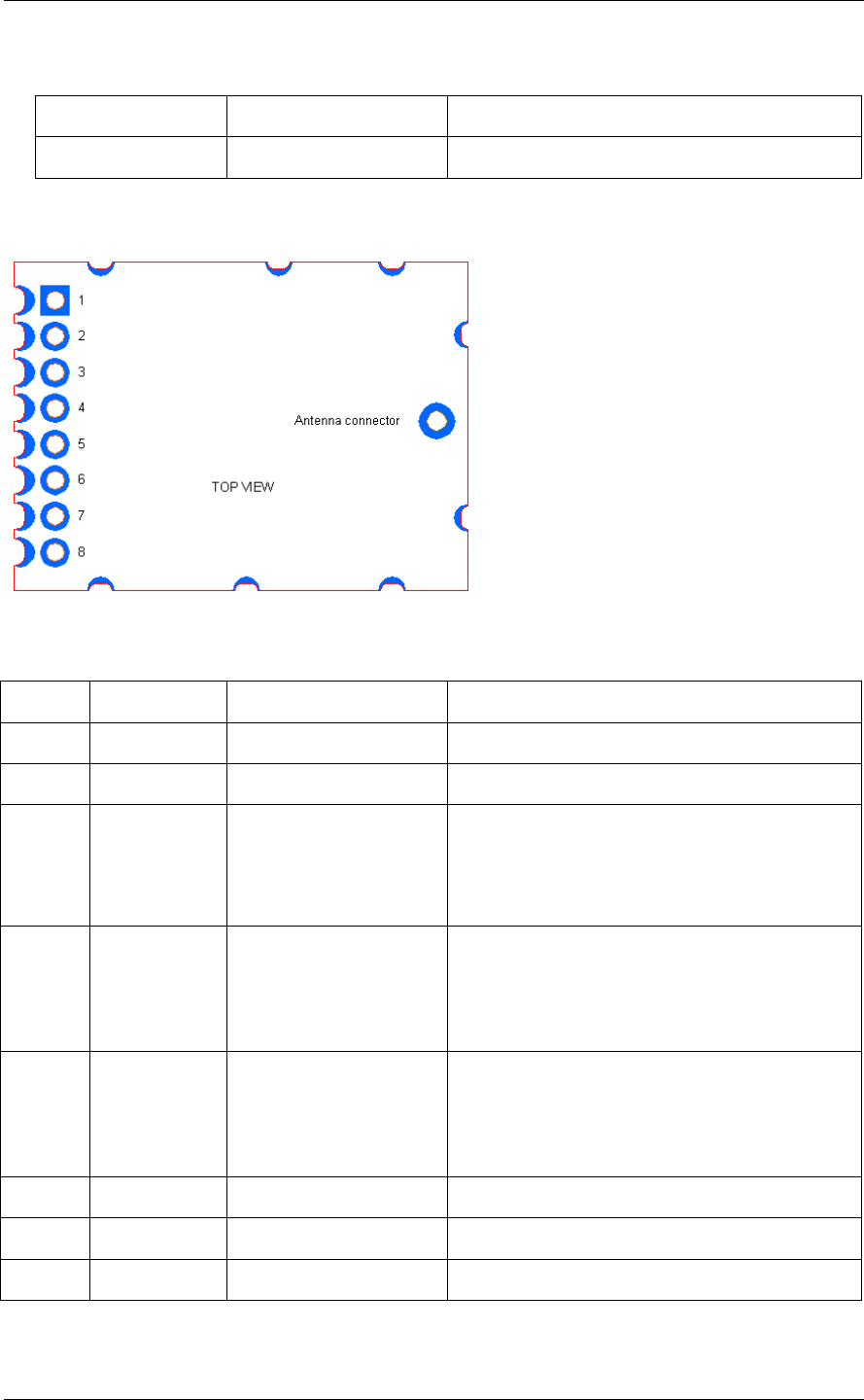
5 Terminal Layout
5.1 Pin Assignment
Pin# Pin name Pin type Description
1 SI Digital Input Serial configuration interface, data input
2 SCLK Digital Input Serial configuration interface, clock input
3 SO /
GDO1
Digital Output Serial configuration interface, data output.
Optional general output pin when CSn is
high
4 GDO2 Digital Output Digital output pin for general use:
• Test signals
• FIFO status signals
5 GDO0 Digital Output Digital output pin for general use:
• Test signals
• FIFO status signals
6 CSn Digital Input Serial configuration interface, chip select
7 GND Ground Ground connection
8 VCC Power 1.8 V to 3.6 V power supply connection
UHF Transceiver Module TRX916 User Manual V 1.0
eQ-3 Limited Page : 6 of 12
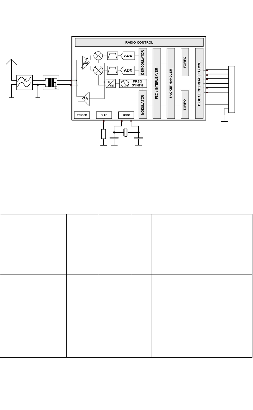
6 Block Diagram
Single Chip RF Transceiver
XTAL
26 MHz
Balun
Lowpass
Filter
A
ntenna
VCC
DATA
Connector
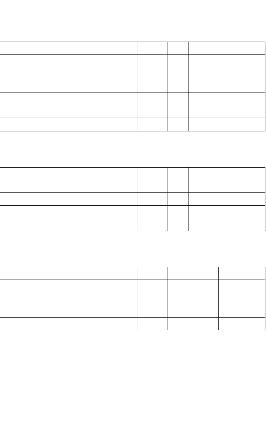
7 Absolute Maximum Ratings
Under no circumstances must the absolute maximum rating given in the following table be
violated. Stress exceeding one or more of the limiting values may cause permanent damage
to the module.
Parameter Min Max Unit Condition
Supply voltage -0.3 3.6 V
Voltage on any digital
pin
-0.3 VCC+0.3
max. 3.6
V
Input RF level +10 dBm
Storage temperature
range
-50 150 °C
Solder reflow
temperature
265 °C According to IPC/JEDEC J-STD-
020C
ESD <500 V According to JEDEC STD 22,
method A114, Human Body
Model
UHF Transceiver Module TRX916 User Manual V 1.0
eQ-3 Limited Page : 7 of 12
8 Operating Conditions
The operating conditions of the TRX916 are listed in the table below.
Parameter Min Typ Max Unit Condition
Operating temperature -20 55 °C
Supply voltage 1.8 3.6 V All pins must have the
same voltage
Frequency 916.47 916.50 916.53 MHz
Data rate 10 kbit/s
FSK deviation ±19 kHz
9 RF Receive Section
TA = 25 °C, VCC = 3.0 V if nothing else stated.
Parameter Min Typ Max Unit Condition
Receiver sensitivity -104 dBm
Saturation -15 dBm
Current consumption 16 mA Receive mode
Current consumption 100 µA Wake On Radio mode
10 RF Transmit Section
TA = 25 °C, VCC = 3.0 V, if nothing else stated.
Parameter Min Typ Max Unit Condition
Output power / Field
strength
93.9 dBµV/m @ 3 m
Harmonics 53.9 dBµV/m @ 3m
Current consumption 17 mA
UHF Transceiver Module TRX916 User Manual V 1.0
eQ-3 Limited Page : 8 of 12
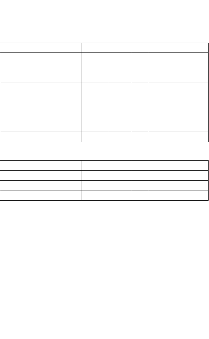
11 DC Characteristics
The DC Characteristics of TRX 916 are listed in the table below.
TA = 25 °C if nothing else stated.
Digital Inputs / Outputs Min Max Unit Condition
Logic “0” input voltage 0 0.7 V
Logic “1” input voltage VCC –
0.7
VCC V
Logic “0” output voltage 0 0.5 V For up to 4 mA output
current
Logic “1” output voltage VCC –
0.3
VCC V For up to 4 mA output
current
Logic “0” input current N/A -100 nA Input equals 0 V
Logic “1” output current N/A 100 nA Input equals VCC
12 Module Dimension
Item Dimension Unit Condition
Width 18.20 mm
Length 25.20 mm
Height 2.65 mm
UHF Transceiver Module TRX916 User Manual V 1.0
eQ-3 Limited Page : 9 of 12
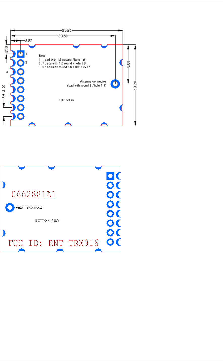
13 Footprint
Dimensions in mm
14 Labeling Drawing

UHF Transceiver Module TRX916 User Manual V 1.0
eQ-3 Limited Page : 10 of 12
15 Software / Register Settings
After start up (connection to power supply) the transceiver module must be programmed
with the necessary main operating parameters. Configuration is done using the SPI
interface. To achieve the technical data and to ensure the FCC requirements according
FCC Part 15, section 15.249 the register settings must be done after start up.
The necessary software parameter (register settings) are available on request from eQ-3
Limited after conclusion of a non-disclosure agreement.
16 Notes Of Design
• Please follow the condition written in this specification.
• This product should not be stressed when installed.
• Please keep this module away from heat.
• The supply voltage should not be exceeding or reverse and should not carry noise
and spikes.
• Please keep this product away from other high frequency circuits.
• Please follow the condition written in this specification about the control signals of
the module.
17 FCC Information
The RF Transceiver Module eQ-3 TRX916 meets the requirements for modular
transmitter approval as described in FCC Public Notice DA00-1407. To fulfill the
requirements of the FCC rules, the OEM (Original Equipment Manufactor) must pay
attention to the following items.
17.1 FCC ID
The FCC Equipment Authorization for this RF Transceiver Module is identified by
FCC ID: RNT-TRX916
and issued to the grantee
eQ-3 Limited, Hong Kong.

UHF Transceiver Module TRX916 User Manual V 1.0
eQ-3 Limited Page : 11 of 12
17.2 FCC Notice
This device complies with Part 15 of the FCC Rules. Operation is subject to the following
two conditions:
(1) this device may not cause harmful interference, and
(2) this device must accept any interference received, including interference that may
cause undesired operation.
17.3 Information to the User
WARNING: Changes or modifications not expressly approved in writing by eQ-3
Limited, Hong Kong may void the user's authority to operate the equipment.
NOTE: This equipment has been tested and found to comply with the limits for a
Class B digital device, pursuant to Part 15 of the FCC Rules. These limits are designed to
provide reasonable protection against harmful interference in a residential installation. This
equipment generates, uses and can radiate radio frequency energy and, if not installed and
used in accordance with the instructions, may cause harmful interference to radio
communications. However, there is no guarantee that interference will not occur in a
particular installation. If this equipment does cause harmful interference to radio or
television reception, which can be determined by turning the equipment off and on, the
user is encouraged to try to correct the interference by one or more of the following
measures:
- Reorient or relocate the receiving antenna.
- Increase the separation between the equipment and receiver.
- Connect the equipment into an outlet on a circuit different from that to which the
receiver is connected.
- Consult the dealer or an experienced radio/TV technician for help.

UHF Transceiver Module TRX916 User Manual V 1.0
eQ-3 Limited Page : 12 of 12
17.4 Labeling Requirements
The Original Equipment Manufacturer (OEM) must ensure that FCC labeling requirements
are met. The transceiver module is labeled with FCC ID: RNT-TRX916. This label is
permanently fixed to the module.
If the module is mounted inside a terminal equipment, the label will not be visible. In this
case the OEM must ensure that the terminal equipment is labeled with an exterior label
containing the expression “Contains Transceiver Module FCC ID: RNT-TRX916” or
“Contains FCC ID: RNT-TRX916”.
See FCC Part 15, Section 2.925 (d) to (f) for detailed information according size, printing
etc..
17.5 RF Exposure
The transceiver module meets all applicable RF exposure requirements. The EUT operates
under the provisions of FCC Part 15, section 15.249 with a maximum allowed field
strength of 50 mV/m, equivalent to 0.8 mW EIRP.
The Original Equipment Manufacturer (OEM) must ensure that the antenna used for this
portable transmitter provides a separation distance of 2.5cm or more from all persons to
satisfy RF Exposure compliance.
17.6 Performance Information
This transceiver module is not designed for use in highly reliable communication systems;
e.g. serving human life inherent systems (systems where failure may result in a physical
risk to a person).
18 Ordering Information
Ordering part number Description MOQ
73927 TRX916 1000
19 Disclaimer
eQ-3 Limited believes the information contained herein is correct and accurate at the time
of this printing. However eQ-3 Limited does not assume any responsibility for the use of
the described product.