eQ 3 WS300PCUS Wireless Weather Station User Manual Manual
eQ-3 Limited Wireless Weather Station Manual
eQ 3 >
Manual
1
Weather Station
WS 300 PC-US
Operating Manual

2
Please read these operating manual completely and thor-
oughly before start up and save it for future reference.
Please hand-over the operating manual as well when you
hand-over the device to other persons for use.
Contents:
1. Introduction .................................................................................4
1.1. Intended usage ...........................................................................4
2. Scope of delivery .........................................................................5
3. Symbol description ......................................................................5
4. Features and functions ................................................................6
4.1. General function ..........................................................................6
4.2. Data logger, USB interface ..........................................................6
4.3. Internal sensors ...........................................................................6
4.4. Display .........................................................................................6
4.5. Software ......................................................................................6
5. Safety information .......................................................................7
6. Battery and environmental information .......................................8
7. Preparations for operation, start up ............................................8
7.1. Starting up the base station ........................................................9
8. Operating and display elements ................................................10
9. Operation/display on the device ................................................11
9.1. Assigning a measurement value to the display .........................11
9.2. Resetting the total rain quantity.................................................12
9.3. Weather forecast display ...........................................................12
9.4. Memory capacity display ...........................................................12
The climate and weather data sensors mentioned in these
instructions are not included in the scope of delivery of the
weather station. These items are to be commissioned and
operated according to the respectively provided operating
manual.

3
10. Configuration, Display unit settings ...........................................13
11. Software installation .................................................................14
12. Firmware update ........................................................................15
13. Changing the batteries ..............................................................15
13.1. Base station ...............................................................................15
13.2. Combination sensor, external sensors, pool sensor .................16
14. Rectifying faults .........................................................................16
15. Transmission range ....................................................................18
16. Maintenance and cleaning.........................................................19
16.1. General ......................................................................................19
16.2. Cleaning the base station ..........................................................19
17. Operation ...................................................................................20
17.1. General ......................................................................................20
17.2. Base station ...............................................................................20
18. Disposal .....................................................................................21
18.1. General ......................................................................................21
19. Technical specifications .............................................................21
20. FCC information ........................................................................22
1. English Edition November 2006
Documentation © eQ-3 Limited Hongkong
All rights reserved. No parts of this manual may be reproduced or processed in any form using electronic,
mechanical or chemical processes in part or in full without the prior explicit written permission of the
publisher.
It is quite possible that this manual has printing errors or defects. The details provided in this manual
are checked regularly and corrections are done in the next edition. We do not assume any liability for
technical or printing errors.
All registered trade marks and copyrights are acknowledged.
Printed in Hong Kong.
We reserve the right to make changes due to technical advancements without prior notice.
00073784 Y2006 V1.0

4
1. Introduction
Dear customer,
thank you for purchasing this product.
The product has been EMC-tested and meets the requirements of
the applicable national regulations. Read the respective FCC infor-
mation as well.
In order to maintain this status and to ensure safe and long-term operation,
you as the user must know the information in these operating manual!
At this time, we would like to bring your attention to the
correct sequence of the procedures for starting up the
product. Observe the installation information in these oper-
ating manual as well as the information on interferences to
the radio transmission between the sensors and the base
station as well.
All of the company names and product designations are trademarks
of the respective owners. All rights reserved.
1.1. Intended usage
The PC weather station WS 300 PC-US creates the interface between
the radio weather sensors that are received by this weather station and
a PC.
The following radio sensors can be used:
- Pool temperature sensor S 300PT-US (water temperature)
- Combination sensor KS 300-2US (temperature, humidity, wind velocity,
rain quantity)
- Combination sensor KS 200US (temperature, humidity, wind velocity)
- Temperature and humidity sensor ASH 2200-1US (temperature and
humidity)
A total of up to 9 of these sensors can be addressed on the base station
(e.g. 1 x KS 300-2US + 8 other sensors).
A temperature, humidity and barometric pressure sensor is also integrated
in the base station for measuring the inside temperature, humidity and the
barometric pressure.
The weather station stores all of the weather data that is recorded in
non-volatile memory.
Reading the data and configuring the WS 300 PC-US is done through
an integrated USB interface and a standard PC with operating system
Microsoft Windows® XP/2000.
F

5
2. Scope of delivery
• Weather station WS 300 PC-US
• Plastic stand
• USB cable
• CD-ROM with driver and software "Weather Prof 2007"
• Operating Manual
• 3 x 1.5 V AA cells
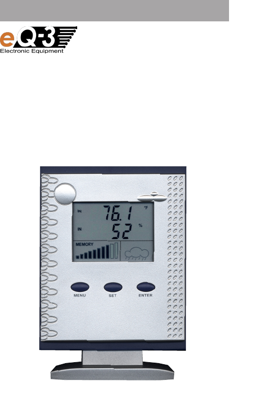
The weather station has its own display, on which the two selected mea-
surement values, the weather forecast and the capacity of the memory in
the device are shown. The respective software reads the recorded data,
displays it in various, selected modes, permits the detailed evaluation and
the archiving of the weather data.
The manufacturer assumes no responsibility for incorrect displays or
measurement values or any results thereof.
The product is intended for private use; it is neither suitable for medical
purposes nor for public information.
The components of this product are not toys. Install all components out
of the reach of children.
This product is operated with batteries. All external sensors transmit their
data to the base station via radio signals in the 433-MHz band (range of
up to 300 ft with no obstacles).
Using the unit for any other purpose than that described
above can lead to damaging the product and other hazards
are also possible.
Read these operating manual carefully and thoroughly, they
contain much important information for setting up, defining
and operating the product.
3. Symbol descriptions
An exclamation mark in a triangle indicates an important
notice in these operating manual, which demands your
attention.
The "Hand" symbol is found next to an operational tip or
note on operation.
F

6
4. Features and functions
4.1. General function
The PC weather station WS 300 PC-US creates the interface between
the radio weather sensors that are received by this weather station
(see chapter 2) and a PC.
4.2. Data logger, USB interface
The weather station receives the data of the radio weather sensors
and stores up to 3200 data records in non-volatile memory (data
logger).
• The memory interval can be adjusted with a resolution of 1 min. in
a range from 5 min. to 60 min.
• Reading the data as well as configuring the WS 300 PC-US is done
through the integrated USB interface.
• A firmware update can be done through the USB interface as
well.
4.3. Internal sensors
The WS 300 PC-US is equipped with internal sensors for temperature,
relative humidity and barometric pressure, which means that no ad-
ditional inside sensors are required for this weather station.
4.4. Display
The weather station has its own display, on which
• two selected measurement values,
• the weather forecast and
• the capacity of the data memory in the device
are displayed. This selection of the measurement value can be done
with three buttons on the unit, without the PC.
4.5. Software
The respective software reads the recorded data, displays it in various,
selected modes, permits the detailed evaluation and the archiving of
the weather data.
The software description is not included in these oper-
ating manual, this description is found on the provided
software CD.
F

7
5.
If there are damages that have been caused by non-ob-
servance of the information in these operating manual,
the guarantee is void. We do not assume any liability for
resulting damage!
We will assume no liability for personal injuries or dam-
age to property caused by improper handling according
to the guidelines in these operating manual or the non-
observance of the safety information. The guarantee is
void in such cases!
Dear customer, the following safety and hazard information does not only
serve as protection for your health, but for protecting the device as well.
Please read
the following points carefully:
• The weather station is only suitable for dry, inside rooms. Do not place
the unit in direct sunlight, next to heat sources, cold, humidity or wet
areas.
• For reasons of safety and certification (CE), the product is not to be
modified, rebuilt or changed in any way.
• Do not leave the packaging material unattended. Plastic bags/ sheets
can become a dangerous toy in the hands of children.
• Handle the product carefully - any force, impact or dropping the
product from any height may damage it.
Safety information

8
6. Battery and environmental information
• Batteries do not belong in the hands of children.
• Make sure that the battery in inserted the right way.
• Do not leave batteries laying around, they have been known to be
swallowed by children and pets. If a battery is swallowed, visit your
Doctor immediately.
• Contact with batteries that are dead or damaged can cause skin irrita-
tion.
Use protective gloves in this case.
• Ensure that batteries do not short-circuit or get thrown in the fire.
There is a danger of explosion!
• Never take a battery apart!
• Never attempt to charge normal batteries.
There is a danger of explosion!
• If not used for any length of time (e.g. when in storage), remove the
batteries to avoid damages caused by leaking, etc.
7.Preparations for operation, start up
Please note:
Always make sure all external sensors are up and runing
(batteries inserted) and then the base station.
If you do not stick that sequence, the base station may not
be able to recognize the external sensors!
Basically, we recommend that you try out the external sensors in a
room before installing them outside. The distance between the base
station and the external sensors should be at least 2 m to avoid inter-
ference. If you determine that e.g. one of the external sensors is not
being received after the installation, it is not possible to be absolutely
sure that the radio reception is insufficient (and the external sensor
is not faulty).
By performing a functionality test first, you will save yourself the extra
time and effort of troubleshooting.
9
7.1. Starting up the base station
• Open the battery compartment on the rear of the base station.
• Insert three batteries (LR6/Mignon/AA), ensuring proper polarity, in the
battery compartment. The preferred batteries are alkaline batteries.
Using rechargeable batteries is possible but the operating dura-
tion will be shorter because of the lower voltage/capacity.
• Close the battery compartment again.
• After inserting the batteries, all segments of the LC display will appear
temporarily and then the version number of the firmware.
• The base station then activates the synchronization mode for 10 min-
utes.
"Sync" appears on the display and a counter, which counts the 10
minutes down, is shown underneath.
Please note:
During the synchronization, no access to the USB interface
of the weather station is possible.
The synchronization cannot be interrupted. Please wait
until the procedure is ended automatically after 10 min-
utes.
• After the synchronization process is complete, the defined mea-
surement values and a weather forecast symbol appears on the
display. The inside temperature and the barometric pressure is
displayed with the factory settings.
• The base station can either be hung on the wall (the respective hanger
eye-slot is located on the rear of the device) or will also stand on a level
surface on the stand.
• If you want to use the desk stand, insert the two small claws of the
stand into the brackets under the battery compartment and pivot the
desk stand forward until the two other claws of the stand latch into the
openings on the underside of the display unit.
F
F
10
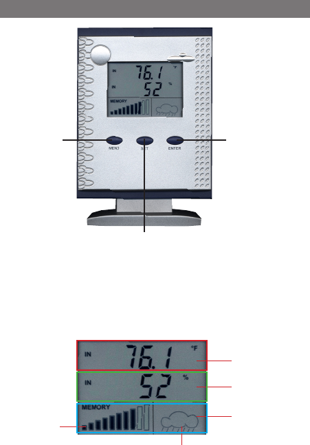
8. Operating and display elements
T1 button
"MENU"
T3 button
"ENTER"
T2 button
"SET"
Top
display line
Middle
display line
Weather forecast
Memory
capacity dis-
play
Bottom
display line

11
Sensor types: Sensor addresses:
tE Temperature 0 Inside sensor
HU Humidity 1...8 ASH 2200-1US (addres-
sable)
PrEs Barometric pressure 9 Combi sensor KS 300-2
The display has two universal display areas in the top and middle dis-
play line, on which the selected weather data can be displayed.
The assignment is done with the three operating push-buttons.
F
9. Operation/display on the device
1x/2x:
MENU
9.1. Assigning a measurement value
to the display
- Press the "Menu" button one time
or two times. The sensor type that
is currently defined is now shown
(see Set-up below) in the first or
second display line.
- Select the desired sensor type by
pressing the "SET" button one or
more times.
- Confirm the selection by pressing
the "Enter" button.
- If Temperature or Humidity is
selected as the sensor type,
press the "SET" button one or
more times to select the desired
sensor (see Sensor Address Set-
up below. The example to the left
shows sensor address 1 as the
selection)
- Confirm the selection again by
pressing the "Enter" button.
Te
Top/
Middle line:
e.g. 1 x:
SET
hu
ENTER
e.g. 1 x:
SET
Te 1
ENTER
When one of the external sensors is selected, "OUT" is shown
in the respective display line, when an inside sensor is selected
"IN" is shown.
Top/
Middle line:
Top/
Middle line:

12
US
rAIn Total rain quantity
or KS200 US
SPEE Wind velocity
9.2. Resetting the total rain quantity
- Set the display to the total rain
quantity message as shown in
9.1.
- To reset the total rain quantity,
press the "Menu" and "Enter" but-
tons at the same time.
1x/2x:
MENU
Te
3 x:
SET
NaiN
ENTERMENU +
9.3. Weather forecast display
- On the right-hand side of the bottom part of the display, a weather
forecast symbol appears forecasting the predicted prevailing
weather for the next 12-24 hours.
Please ensure that the precision of the weather forecast
is at approx. 70% with the observed barometric pressure.
Deviations are normal.
10.4. Memory capacity display
- A bar graph is shown in the lower left-hand side in the bottom
display line. The more that the bar is dark, the more memory that
is being used.
- If the memory is 90% full, the display begins to flash. The data
should be read using the "Weather Prof 2007" software as soon as
possible.
Please ensure that no more (current) data is saved when
the memory is full. All of the data saved to that point in
time is retained.
F
F
Top/
Middle line:
Top/
Middle line:

13
10. Configuration
Display unit settings
You can select measurement values
according to the American or Euro-
pean standards for the display unit.
-
Press buttons "MENU", "SET" and
"ENTER" at the same time to switch
between the units for temperature,
humidity, wind velocity, barometric
pressure and rain quantity.
The example at the side shows
switching the temperature display
in the top display line and the baro-
metric pressure display in the middle
display line.
MENU
80.2
30.03
°F
inHg
26.8
1017
°C
hPa
SET ENTER
+ +
American standard: European standard:
Temperature: °F Temperature: °C
Humidity: % Humidity: %
Wind velocity: mph Wind velocity: km/h
Barometric pressure: inHg Barometric pressure: hPa
Rain quantity: inch Rain quantity: mm

14
The following system prerequisites apply for operating the "Weather
Prof 2007" software:
· Operating system MS Windows 2000/XP
· Min. 1 GHz clock frequency
· Min. 256 MB RAM
· approx. 150 MB available hard disc space for the program
· approx. 100 MB available hard disc space for the database
· The file system must be formatted with NTFS (Standard option)
· The Windows-Installer-Service must be installed (Standard option)
The provided USB cable with connector type A and Mini-B, 5-pole con-
nector is required for connecting to a USB port on the PC.
- Connect the weather station to the USB port of the computer with a
USB cable.
- Insert the provided CD-ROM into the CD drive of your computer.
- A start screen appears, which describes the four steps of the set-up
procedure.
- Follow these instructions, step for step until the installation is complete.
Observe the instructions on the CD-ROM as well.
- The "Weather Prof 2007" program is then started via the Desktop or
the through the program menu.
- The program description can be found in the help menu under "Man-
ual".
11. Software installation

15
12. Firmware update
A firmware update for the main controller of the WS 300 PC-US can be
started with the provided software via the USB interface of the weather
station.
- Start the Update program (Menu "Tools", Menu point "Firmware up-
date") in the "Weather Prof 2007" program and follow the program in-
structions.
If the update procedure is started by accident, it can be
aborted right up until step 5.
If the update mode has also been activated on the device
according to the instructions from the software, the weather
station must be separated from the USB for a few seconds
and the batteries are to be removed from the device.
The function of the device is not affected in this case, it
continues to work with the previous firmware after starting
operation again.
Depending on which batteries or rechargeable bat-
teries you use, the interval for changing them is dif-
ferent. High quality alkaline batteries are longer last-
ing, rechargeable batteries or cheap zinc-carbon
batteries must be changed much more often.
13.1. Base station
The low-battery symbol appears on the display ( ), the batteries are
to be replaced with new ones.
To avoid losing any data in this case, the WS 300 PC-US should be con-
nected with the running PC via the USB cable while changing batteries.
• Always replace the complete set of batteries.
• Do not mix full with "half-full" batteries.
•
Always use batteries of the same type and the same manufacturer.
F
13. Changing the batteries
F

16
• Do not mix batteries with rechargeable batteries.
• As mentioned previously, rechargeable batteries can be used but the
time
between charging is much shorter than the life-span of good batteries.
• Follow the procedures described in chapter 7.1 for changing the bat-
teries.
After changing batteries, the battery symbol will continue to
be displayed for up to 15 minutes.
13.2. Combination sensor, external sensors, pool sensor
If the display for the respective sensor is missing for more than 24 hours,
the batteries are to be replaced for new ones as described in the respec-
tive operating manual.
Check for whether there is a fault in the radio transmission and
whether this may be the cause of the missing data transmis-
sion. This will also cause the display to disappear from the
display of the base station.
The cause could be e.g. a metal object in the signal path (e.g.
parked vehicle).
14. RectifyObserve all safety information in these
operating manual!
F
Problem Help in solving problems
No reception • The distance between the base station and exter-
nal sensors is too great. Move the location of the
external sensors.
• Obstacles or shielding materials are blocking the
radio reception. Change the location of the external
sensors and the base station.
• The batteries in the external sensors are weak or
dead. Try installing new batteries in the external
sensors.
• Another transmitter on the same or neighboring
frequency is disrupting the radio signals of the
external sensors. This can be e.g. wireless head-
phones, wireless speakers or other devices.
F

17
Interfering with
other devices by
theexternal sen-
sors
• The external sensors send their external sensor
data to the base station approx. every 3 minutes
for a duration of 0.1 second (100 ms). During this
short time period, interference may be caused
on other devices.
As an example, a short interference can be heard
in wireless headphones every 3 minutes.
Problems with
synchronization
• When the batteries are inserted in the external
sensors and the base station (precisely maintain
this sequence!!), these devices are put in syn-
chronization mode.
A data telegram is set out every 4 seconds,
which accelerates the recognition and external
sensor reporting to the base station.
In order to force a new synchronization, remove
the batteries from the base station and the ex-
ternal sensors. Wait at least 60 seconds before
inserting the batteries in the external sensors and
then into the base station (follow this sequence
precisely - first batteries in all existing external
sensors and then in the base station).
This will cause all values/data that the base sta-
tion has stored (e.g. minimum values, maximum
values, temperature limit values) to be lost.
• Before putting your external sensors e.g. in the
garden, perform a functionality test as described
in the beginning of chapter 7.
These products are not normally running continu-
ally; the radio reception can e.g. be just fine the
following day, which makes the search for the
cause that much harder.
If possible, set other devices to a different
frequency, which may resolve the reception
problems with the weather station.
Problem Help in solving problems
Continued:
No reception

18
F
15. Transmission range
The range of transmission for the radio signals to the base station is up
to 300 ft in optimal conditions. This is often referred to as the "Free-field
range".
This ideal allocation (e.g. base station and external sensor
on a smooth, even area with no trees, houses, etc.) is almost
never achieved in reality.
Normally, the base station is set up in the house, the combination sensor
in the garden and other outside sensors e.g. in the neighboring building
(e.g. in an aviary) or garage.
The transmission distance can be greatly reduced by:
• Walls, steel concrete floors
• Coated/gas-filled insulated glass
• Vehicles
• trees, bushes, earth, rock
• Proximity to metallic and conductive objects (e.g. radiator)
• Proximity to the human body
• Broadband interference, e.g. in residential areas (DECT telephone,
cell-phones, wireless headsets, wireless speakers, other radio weather
stations,
baby-phone, etc.)
• Proximity to electric motors, transformers, power supplies, computer
• Proximity to poorly shielded or computers with the covers removed
or other
electrical devices
Since the characteristics of every location are different, a definite
reception range cannot be guaranteed.
If the base station is not receiving data from a pool sensor, combination
sensor or any other external sensors (even with new batteries), the distance
between the external sensor and the base station should be decreased,
change the location.
Observe the information provided in chapters 7 and 14 of these operating
manual.
F

19
16. Maintenance and cleaning
16.1. General
Perform a regular inspection of the technical safety of the product, e.g.
damaged housing.
If you are sure that operation poses a threat of danger, the product is to
be taken out of operation and made so that accidental operation is impos-
sible. Remove the batteries.
The product poses a threat of danger if
• the device shows visible damage,
• the device no longer functions and
• after longer period of storage under unfavorable conditions or
• after severe transport conditions.
Before cleaning or maintaining the device, make sure that you follow
the following safety information:
Remove the batteries before cleaning, maintenance or start
up.
There are no parts inside the product that can be service by the
customer; the housing is not to be opened.Repairs are only to be
completed by technicians qualified for working with the
respective dangers and with the respective certifications.
16.2. Cleaning the base station
Dust can be removed easily with a vacuum cleaner and with a clean soft
brush. Hold the opening of the vacuum cleaner up close to the base sta-
tion (contact can cause scratches, do not touch!) and remove the dust
with a brush. The dust that is loosened will be removed by the vacuum
cleaner.
To clean the outside of the product, a soft, dry and lint-free cloth can
be used.
For heavier dirt, the cloth can be dampened slightly with warm water.
Do not use aggressive cleaning agents or chemical solutions since it can
affect the housing or even the functionality.

20
17. Operation
Observe all safety information in these operating manual!
General
The product is not to be opened or dismantled (with the exception of that
work described in these operating manual). There are no parts that require
maintenance inside the product.
Falling from even low heights will damage the product.
Base station
Avoid the following adverse environmental conditions for base station
operation:
- Wet or overly high humidity
- Extreme cold or heat
- Direct sunlight
- Dust or combustible gasses, vapors or solvents
- heavy vibrations
- strong magnetic fields, as close to machines or loudspeakers
Do not use the product after sudden introduction into a cold or warm room.
The condensation caused in this case can damage the product.
Wait until the base station has adjusted to the room temperature. This
can take several hours.
The set-up location should be chosen so that the base station stands
securely and cannot fall over - Danger of injury.
Valuable furniture or furniture with surfaces that scratch easily should be
protected from damage with a suitable covering before setting up the
base station on top of them.
17. Terminology

21
18. Disposal
18.1. General
Dispose of the device according to the applicable legal regulations!
Inside temperature measurement range: 32°F to 140°F (0°C to +59.9°C)
Outside temperature measurement range (KS300-2US):
-21.8°F to 175.8°F (-29.9 ˚C to +79.9˚C)
Resolution: .................................................................................... 0.1 °F
Relative humidity measuring range: ......................................0 % - 99 %
Resolution: .......................................................................................1 %
Rain quantity: ............................................0 to 39.33 inch (0 to 999 mm)
Wind velocity: ............................................ 0 to 124 mph (0 to 200 km/h)
Transmission frequency: ....................................................... 433.92 MHz
Free-field range: ......................................... up to 300 ft (see chapter 15)
Power supply: .................................................3 x 1.5 V AA/LR6/Mignon
PC port: ............................................................. USB 1.1, Mini-B, 5-pole
Operating temperature range: ........................................32 °F to 122 °C
Display area (W x H): ......................................................... 2.2 x 1.6 inch
Dimensions (W x H x D): 4.1 x 5.7 x 2.2 inch (with stand)
4.1 x 5 x 1.3 inch (without stand)
19. Technical specifications

22
FCC ID: RNT-WS300PCUS
Changes or modifications not expressly approved in writing by eQ-3
Limited may void the user‘s authority to operate the equipment.
NOTE: This equipment has been tested and found to comply with the
limits for a Class B digital device, pursuant to Part 15 of the FCC Rules.
These limits are designed to provide reasonable protection against harmful
interference in a residential installation. This equipment generates, uses
and can radiate radio frequency energy and, if not installed and used in
accordance with the instructions, may cause harmful interference to radio
communications. However, there is no guarantee that interference will not
occur in a particular installation. If this equipment does cause harmful
interference to radio or television reception, which can be determined by
turning the equipment off and on, the user is encouraged to try to correct
the interference by one or more of the following measures:
- Reorient or relocate the receiving antenna.
- Increase the separation between the equipment and receiver.
- Connect the equipment into an outlet on a circuit different from that to
which the receiver is connected.
- Consult the dealer or an experienced radio/TV technician for help.
The internal antenna used for this mobile transmitter must provide a
separation distance of at least 20 cm from all persons and must not
be co-located or operating in conjunction with any other antenna or
transmitter.
This device complies with Part 15 of the FCC Rules. Operation is subject
to the
following two conditions:
(1) this device may not cause harmful interference, and
(2) this device must accept any interference received, including interfer-
ence that may cause undesired operation.
20. FCC information
23
24