eQ 3 WS300US Weather Station Set User Manual UserMan
eQ-3 Limited Weather Station Set UserMan
eQ 3 >
UserMan

1
Radio Weather
Station WS 300US
Operating instructions
ELV Electronics Ltd. Hong Kong
((New photo))

2
1st English edition January 2004
Documentation © 2003 ELV Electronics Limited
All rights reserved. This handbook must not be reproduced in any form, even in excerpts, or duplicated or
processed using electronic, mechanical or chemical procedures without written permission of the publisher.
This handbook may contain mistakes and printing errors. The information in this handbook is regularly
checked and corrections made in the next issue. We accept no liability for technical mistakes or printing
errors, or their consequences.
All trademarks and patents are acknowledged.
Printed in Hong Kong
Modifications due to technical improvements may be made without prior notification.
57010 Y2004V1.0
3
Contents
1. General information and functioning ........................................................................................................ 4
Quick overview of the display fields on the main display ............................................................................. 6
2. Preparation for operation........................................................................................................................... 7
2.1. The outdoor sensors ..................................................................................................................................... 7
Commissioning the KS 300US, installing batteries, erection ....................................................................... 7
2.2. Base unit, installing batteries, erection ......................................................................................................... 8
3. Operation ..................................................................................................................................................... 9
3.1. Basic settings, configuration ........................................................................................................................ 9
Setting the date and time ........................................................................................................................... 10
Setting the degree of longitude and degree of latitude .............................................................................. 11
Setting the time zone .................................................................................................................................. 12
Entering the calibration value for the rain sensor ....................................................................................... 13
Setting the unit for rainfall measurement .................................................................................................... 13
Assigning the indicator path ....................................................................................................................... 14
Setting the unit for wind speed measurement ............................................................................................ 14
Leaving configuration mode ....................................................................................................................... 14
3.2. Operation .................................................................................................................................................... 15
Selecting the indoor temperature display (temperature/dew point) ........................................................... 15
Selecting the outdoor temperature display (temperature/dew point/wind chill) ......................................... 15
Selecting the outdoor sensor ..................................................................................................................... 15
Selecting the rainfall display period ............................................................................................................ 15
Resetting the total rainfall quantity ............................................................................................................. 15
Calling up/deleting MIN/MAX values .......................................................................................................... 16
3.3. Additional functions .................................................................................................................................... 17
Moon phase display ................................................................................................................................... 17
Wiz Kid ........................................................................................................................................................ 17
Weather forecast ......................................................................................................................................... 17
Wind symbol display (wind sock) ............................................................................................................... 17
Instant rain display ...................................................................................................................................... 18
Comfort indicator ........................................................................................................................................ 18
4. Changing batteries ................................................................................................................................... 18
5. Information on fault removal ................................................................................................................... 19
6. Range ......................................................................................................................................................... 20
7. Maintenance and servicing information ................................................................................................. 20
7.1. Cleaning the rain sensor ............................................................................................................................. 20
7.2. Calibrating the rain sensor .......................................................................................................................... 22
8. Technical data ........................................................................................................................................... 23
9. Explanation of terms ................................................................................................................................23
10. Intended usage, exclusion of liability, safety instructions .................................................................... 25
11. FCC Information ......................................................................................................................................... 25
Position table showing selected locations in the US .................................................................................. 26

4
1. General information and functioning
The WS 300US Radio Weather Station is a high-quality universal weather measu-
ring system that processes a wide range of weather data and additional informa-
tion and can display both current values and forecasts.
All relevant data are displayed simultaneously on the LCD display, while addition-
al data can be called up at the press of a button as required.
The figure of the "Wiz Kid" is a special feature. Its clothes indicate the actual
temperature range of the outside temperature, its hair and scarf the current wind
speed range and an umbrella forecast precipitation and the beginning and
current precipitation.
The weather station is operated completely wireless by means of batteries; all
external sensors transmit their data by radio on the 433 MHz frequency (range up
to 100 m in the open).
The display and control possibilities of the WS 300US at a glance:
Display of the indoor temperature and humidity
- Temperature display in ˚F
- Can be switched over to display the dew point indoors
- Storage of the minimum and maximum temperature with the time/date of
occurrence
- Storage of the minimum and maximum humidity with the time/date of
occurrence
- Comfort zone indicator
- Graphic indicator path for the last 24 h
Display of one of max. 9 outdoor sensors (temperature and humidity)
- Optional display of temperature, dew point or wind chill temperature
- Storage of the minimum and maximum temperature with the time/date of
occurrence
- Storage of the minimum and maximum humidity with the time/date of
occurrence
- Graphic indicator path for the last 24 h
Display of the wind speed
- Selectable units: km/h, m/s, mph
- Storage of the maximum wind strength with time/date of occurrence
- Graphic additional display (wind sock) for light, moderate and strong wind
Display of the amount of rainfall in mm, l/m2 or inch for:
- Total quantity since the last reset / last hour / last 24 h
- Storage of the maximum amount per hour and per day
- Additional display for commencing rain (instant rain display)
5
Display of the change / trend in air pressure:
- Graphic display of the changes in the last 24 h
- Display of the air pressure trend in 5 steps: rising steeply, rising, no change,
dropping, dropping steeply
Symbolic indication of the weather forecast: rainy, cloudy, fine, sunny
Indication of the time and date
- Integrated quartz clock
Indication of sunrise and sunset
- Based on the location data to be entered individually, can be calculated in the
range of the degrees of latitude -60 to +60˚ N
Moon phase display
- Display of the current moon phase: new moon, waxing moon, full moon, waning
moon
"Wiz Kid" weather display
Echoing the almost forgotten weather house, where in bad weather a person
would step out of the door with an umbrella and in good weather would be lightly
clothed, the WS 300US has its own "Wiz Kid".
The behaviour of this figure depends on several weather factors, enabling
someone to see at a glance what sort of clothing would be appropriate for
wearing outside in that weather. The current parameters for outdoor temperature,
humidity, wind and rain are not the only factors to be analysed. The weather
forecast also plays a major role here. Thus the "Weather Willie" can appear in a
variety of forms and clothing according to the weather situation.
Please refer to page 24 of these operating instructions for a detailed description of
the analytical criteria.
Please read these instructions carefully from start to finish before initial start-
up to avoid functional breakdown and faulty operation. Keep the instructions
available for future reference.
Pay particular attention to the installation and calibration instructions for the
instruments for recording the measured values.
6
HUMIDITY
total
INDOOR
RAIN WIND
HUMIDITY
OUTDOOR
HISTORY
SUNRISE SUNSET
TIME DATE
SENSOR
%%
16 020
24 12 84
°F
inch mph
AM
AM
PM
°F
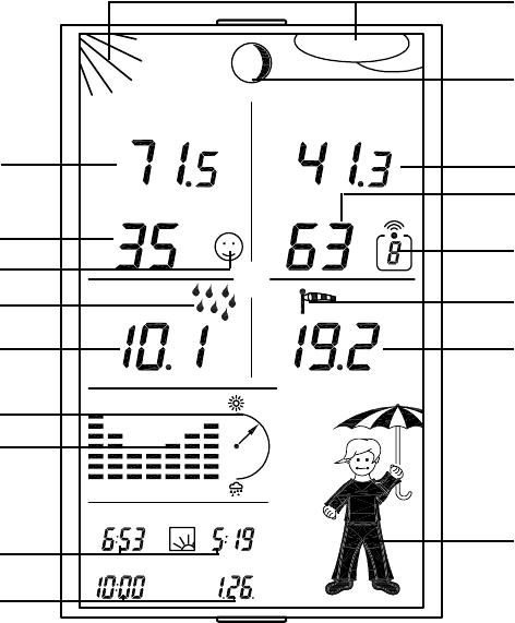
Quick overview of the display fields on the main display
1. Current temperature, indoor sensor
2. Current humidity, indoor sensor
3. Comfort zone indicator for the display of pleasant/unpleasant climate
4. Display for the onset of rain
5. Display of the rainfall, in this case in the last 24 h
6. Tendency display for air pressure: rising steeply, rising, constant, falling,
falling steeply
7. History display, in each case relative to the value chosen in the configuration; in this
case the air pressure
8. Display of sunrise and sunset
9. Time and date display
10. Animated "Wiz Kid" multi-weather display
11. Wind speed display
12. Wind speed display (light, moderate, strong)
13. Display of the current chosen outdoor sensor; no display if combi-sensor is chosen
14. Current humidity of the selected outdoor sensor
15. Current temperature of the selected outdoor sensor
16. Moon phase display
17. Weather forecast display (sunny, bright, cloudy, rainy)
The respective units of measurement are assigned via the weather station configuration (see
further instructions).
1
2
15
14
5
6
7
4
3
8
9
10
12
11
13
16
17
7
2. Preparation for operation
Start up all outdoor sensors first, then the base station.
2.1. The outdoor sensors
The following outdoor sensors are available for the weather station:
- KS 300US combi-sensor: This is a permanently addressed combination sensor
consisting of rain sensor, instant rain detection sensor, wind speed sensor, outdoor
temperature/humidity sensor and integrated transmitter unit. Operation is by means
of three Mignon batteries.
- ASH 2200US outdoor temperature/humidity sensor: Addressable sensor, battery-
operated (2 LR6/Mignon/AA batteries). Up to 8 sensors of this type can be used for
operation on the WS 300US.
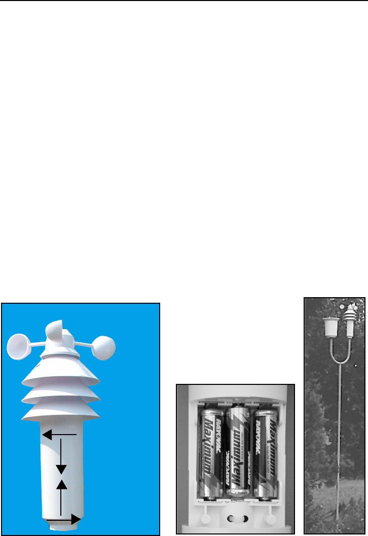
Commissioning
KS 300US
The KS 300US is commissioned according to the following procedure:
- Assemble the plug mast of the sensor by screwing the individual tubes together
using the threaded adapters, insert the earth spike at the base and screw the
sensor holder on at the top.
- Open the housing of the sensor by turning the housing anticlockwise and pulling
from underneath (see picture bottom left).
- Insert three Mignon batteries into the battery compartment as indicated by the
pole markings in the compartment.
To detach:
Turn to the left,
remove from
underneath
To attach:
Attach,
turn to the right ++
+
–
––
Bottom
8
The sensor will now be in synchronisation mode for about 5 minutes, during which
one data packet will be sent every 4 seconds.
- Close the housing again by pushing it up and turning it clockwise until it engages.
- Erect the now fully assembled sensor within the possible transmission radius (up to
100 m in the open, but make allowances for the attenuating effects of walls etc.)
so that it stands alone in such a way that both precipitation can fall directly into
the rain sensor and that the wind measurement is not distorted by nearby build-
ings, trees etc.
A sunny spot is possible, since the temperature sensor is located in a shaded and
ventilated area of the housing.
- Push the earth spike far enough into the soil for the sensor to stand securely and
the devices to be about 2 m above ground level.
ASH 2200US
For the installation, addressing and commissioning of this sensor, please refer to
the operating instructions supplied with the unit.
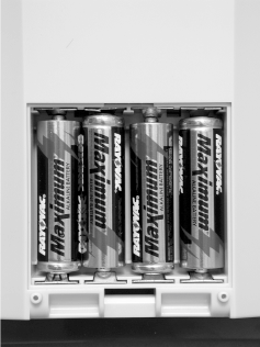
2.2. Base unit
The weather station is operated with 4 x 1.5 V LR6/Mignon/AA (alkaline) batteries.
- If the stand of the weather station is already assem-
bled, detach it by folding back the station on the
table.
- Open the battery compartment on the rear of the
station by lifting it up and insert four Mignon batter-
ies according to the poling marked in the compart-
ment.
- Close the battery compartment again.
- After a display test phase in which the display shows
all the available segments, the weather station goes
into a synchronisation phase for 15 minutes. During
this time all the received radio weather sensors will
be displayed immediately one after the other. If all
the sensors you installed have already been received,
you can end synchronisation mode early by pressing
any key, provided that the KS 300US has also left its synchronisation mode.
- After synchronisation all weather data are displayed as normal as shown in page
6. Only sunrise and sunset and the moon phase are not yet displayed, because
the clock and calendar have yet to be set.
- Configure the base unit as described under 3.1.
+
+
+
–
––
Bottom +–
9
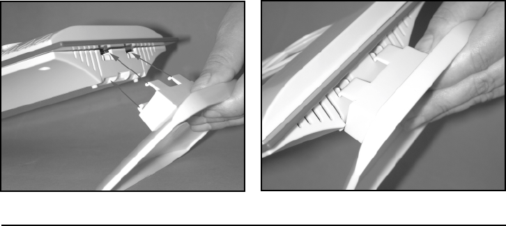
Setting up/Wall mounting
Depending on requirements, the weather station can be hung on a vertical surface
(wall) by means of the attachment eye or set up on a horizontal surface using the
fold-out desk stand.
- The desk stand is erected as illustrated in the following pictures. It is important
that the short claws of the desk stand are first inserted into the brackets on the
rear of the unit.
- The desk stand is then tilted forward until the long claws engage in the snap-in
brackets on the bottom side of the station.
3. Operation
After the installation of the radio sensors and the subsequent commissioning of the
base unit, the transmitted and converted data appear in the appropriate fields of
the display. If the display does not appear you will find information on trouble-
shooting in section 6 ("Faults").
3.1. Basic settings, configuration
The weather station is delivered in such a way that it is operational in its basic
functions (apart from moon phase, sunrise and sunset display, date and time)
immediately after commissioning.
However, further configuration is required in order to make use of the additional
time-related functions.
The following settings are required:
- Year, date, time
- Status of the daylight saving time (On/Off)
- Input of the longitude and latitude of the location
- Time zone input
Expanded settings:
- Rain sensor calibration
- Unit of rain quantity
- Assignment of the indicator path (air pressure, inside and outside temperature)
- Unit of wind strength
10
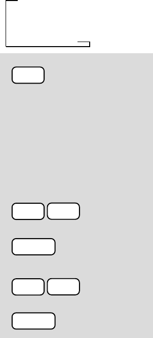
In configuration mode the keys have the following functions:
IN →not used
SENSOR →EXIT Leave configuration mode
MIN/MAX →+ Increase value
RAIN →–Decrease value
OUT →NEXT To the next setting
This key assignment is also shown on the rear of the weather station.
Please note!
If you press and hold down the "+" or "-" keys during the individual setting opera-
tions, the figures will run through more quickly.
After every setting operation you can either leave configuration mode by pressing
the "EXIT" key or proceed to the next setting via the "NEXT" key.
Configuration is performed in this order:
→Year → Month → Day → Minutes → Hours → Daylight saving time→
Deg. latitude (LA = Latitude) → Deg. longitude (LO = Longitude) → Time zone (ti)
→ Rain sensor calibration→ Rain quantity unit → Assignment of indicator path
→ Wind unit
Calling up configuration mode
Configuration mode is called up by pressing
the "IN" key for about 2 seconds. When the
key is released the corresponding display is
shown.
You can leave configuration mode at any time
as described in "Leaving configuration
mode".
Setting the date and time
Set the current year using the "+" and "-" keys.
Press "NEXT" to go to the month setting.
Set the month using the "+" and "-" keys.
Press "NEXT" to go to the day setting.
IN [2 seconds]
+ Year
–
NEXT
+ Month
–
NEXT

11
Set the day using the "+" and "-" keys.
Press "NEXT" to go to the minutes setting.
Set the minutes using the "+" and "-" keys.
Press "NEXT" to go to the hours setting.
Set the hours using the "+" and "-" keys.
Press "NEXT" to go to the setting of the
daylight-saving-time status. This is indicated
by "dSt" in the display.
Setting the status of the daylight
saving time
Press "-" to switch off the daylight saving time
or press "+" to switch on the daylight saving
time.
Press "NEXT" to go to the latitude setting.
This is indicated by "LA" in the display.
Entering latitude and longitude
Indication of the exact position of the weather
station is required so that sunrise and sunset
times can be calculated. The degree of
latitude can be set in a range between –60.0
°
and +60.0
°
. The factory setting is the position
of xxx. You can determine your position in a
number of ways:
-In the appendix is a table showing the
coordinates of many towns and cities
in the US. You can select a location
near you and enter its coordinates.
-If you have a GPS navigation system,
e.g. in the car or a mobile device, you
+ Day
–
NEXT
+ Minute
–
NEXT
+ Hour
–
Display "dSt"
NEXT
Hour
+–
Display "dSt"
NEXT

12
can copy its position indication to obtain
an exact location.
-Exact coordinates can also be obtained
from the Internet. There are numerous
sites which deal with navigation.
Remember that strictly speaking the
information for sunrise and sunset applies
only by the sea or for land that is completely
flat. Mountains, high forests etc. can reduce
the actual daytime considerably.
Even in an ideal location the figures may
deviate by a few minutes since an approxi-
mation formula is used for the calculation.
Set the latitude using the "+" and "-" keys.
Example: for 38,9˚, enter: 389
Press "NEXT" to go to the longitude setting.
This is indicated by "LO" in the display.
Set the longitude using the "+" and "-" keys.
Example: for 283,0˚, enter: 2830
Press "NEXT" to go to the time zone setting.
This is indicated by "ti" in the display.
Setting the time zone
Indication of the time zone is required so that
the sunrise and sunset times can be calcu-
lated. The actual difference from UTC (Uni-
versal Time) must be entered.
Enter the actual value for your time zone using
the "+" and "-" keys.
+ Latitude
–
NEXT
+ Longitude
–
NEXT
+Time zone
–
Display "LO"
Display "ti"

13
All the settings required for the weather
station to operate normally have now been
made. The expanded settings are not needed
for normal operation.
Press the "EXIT" key to leave configuration
mode and return to normal mode.
Press the "NEXT" key in order to make
expanded settings and to calibrate the rain
sensor.
Entering the rain sensor calibration
value
The rainfall measuring system is delivered ex-
works with a high accuracy, so that normally
no calibration is required.
The calibration value must initially be
determined in normal mode as described
under 7.2.
Enter the previously calculated calibration
value using the "+" and "-" keys.
Press "NEXT" to proceed to inputting the unit
of rainfall measurement.
Setting the unit for rainfall
measurement
The unit for the rainfall is indicated in the
"RAIN" field and can be expressed as l/m2
or as mm.
Select the desired unit using the "+" and "-"
keys.
Press "NEXT" to get to the input function
for the indicator path.
EXIT
+ Calibration
value
–
NEXT
Quit
configuration
or
NEXT Expanded
settings
+Unit for
rainfall
–
NEXT
14
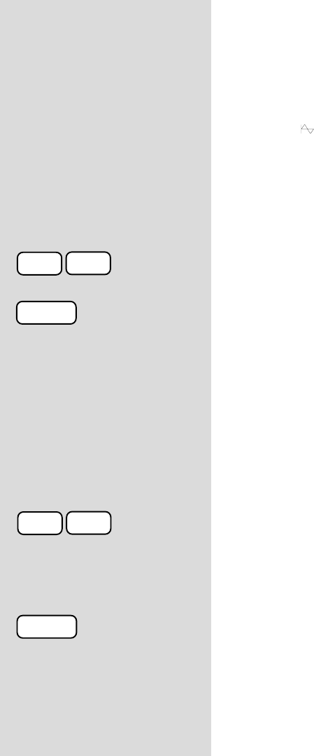
Assigning the indicator path
The movement of the air pressure, the inside
or the outside temperature can be illustrated
in the display field of the graphic indicator
path. If the indicator path is assigned to one
of the two temperature displays, the addition-
al symbol " " appears in the relevant display
field.
Abbreviations in the display field:
P→Air pressure
O→Outside temperature
I→Inside temperature
Select the desired assignment using the "+"
and "-" keys.
Press "NEXT" to proceed to inputting the unit
of wind speed measurement.
Setting the unit for wind speed
The unit can be chosen from km/h, m/s or
mph and is displayed in the "WIND" field.
Select the desired unit using the "+" and "-"
keys.
Leaving configuration mode
Press the "EXIT" key to leave.
+ Assign
history
–
NEXT
+Unit for
wind
–
EXIT
15
3.2. Operation
Selecting the indoor temperature display
In normal mode the
"INDOOR" display field shows the indoor temperature and
indoor humidity.
- By repeatedly pressing the "IN" key, you can switch between displaying the indoor
temperature and the associated dew point value:
→ Indoor temperature → Dew point
Selecting the outdoor temperature display
In normal mode the
"OUTDOOR" display field shows the outdoor temperature and
outdoor humidity of the chosen outdoor sensor.
- By repeatedly pressing the "OUT" key, you can switch between displaying the
outdoor temperature and the associated dew point value or the perceived
temperature (wind chill):
→ Outdoor temperature → Dew point → Wind chill
Selecting the outdoor sensor
The "Sensor" display field shows the outdoor sensor you have just selected, along
with its address. Only active sensors (received in the synchronisation phase) are
displayed.
The outdoor sensors 1 to 8 (ASH 2200US) and the combi-sensor (no address shown)
can be displayed.
- You can select the desired sensor by repeatedly pressing the "SENSOR" key.
Selecting the rainfall display period
- By repeatedly pressing the "RAIN" key, you can switch between the indication for
the last hour, the last 24 hours or the total quantity since the last reset or since the
batteries were inserted:
→ 1 h → 24 h → Total
Resetting the total rainfall quantity
- Press and hold the "RAIN" key down for about 2 s to reset the total rainfall quantity
immediately after the key is released.
16
Calling up MIN/MAX values
The minimum and maximum values reached for the indoor and outdoor temperature
and indoor and outdoor humidity since the data were last deleted are saved. For
the wind speed and rainfall measurement, only the MAX values are saved.
For all figures, the date and time that the extreme value occurred are also saved.
The stored data can be called up as follows:
Calling up minimum values
- Press the "MIN/MAX" key once:
The display shows all minimum values in the relevant display fields. "MIN" appears
in the middle of the display. There is no indication for wind and rain.
Calling up maximum values
- Press the "MIN/MAX" key twice:
The display shows all maximum values in the relevant display fields. "MAX" appears
in the middle of the display.
- Press the "MIN/MAX" key again to return to the normal display.
Displaying the time/date for an individual extreme value, deleting the extreme
value
For each individual extreme value you can, if necessary, view the relevant time
and date on which it occurred.
- Select the display of the minimum values (press the "MIN/MAX" key once) or the
maximum values (press the MIN/MAX" key twice).
- Press the "SENSOR" key repeatedly. Now only one display field with its extreme
value will be shown in turn, and underneath in the time display the time and the
date on which it occurred, shown in the following order.
Indoor temperature → Indoor humidity → Outdoor temperature → Outdoor
humidity → Rainfall (MAX only, not in the case of TOTAL) → Wind speed (MAX
only)
- Press the key once more to return to the complete display of all extreme values
(MIN or MAX).
Deleting MIN/MAX values
- If the individual extreme values are called up as described above, you can delete
each of them in turn by pressing and holding the "RAIN" key down.

17
3.3. Additional functions
Moon phase display
The moon phase is displayed with the following symbols:
Wiz Kid
The Wiz Kid is an animated figure that indicates several weather factors at the
same time:
Outdoor temperature (combi-sensor only)
- The clothing worn depends on the outdoor temperature on the combi-sensor.
Rain
- If the forecast function has predicted rainy weather, the figure carries a furled
umbrella.
- If rain is beginning, the figure carries an open umbrella.
Wind speed
- At wind speeds in excess of 12,4 mph (moderate wind) the hair of the Wiz Kid
waves. If the temperature is less than 57,2 ˚F at the same time, the scarf that he
now wears will also wave in the wind.
Weather forecast
- The weather forecast symbols at the top of the display indicate the following
predictions:
· Clouds with rain →Rainy
· Clouds →Cloudy
· Clouds with sun →Fine
· Sun →Sunny
Other display options
Wind symbol display (wind sock)
- The wind sock symbol in the "WIND" display field allows you to see at a glance
whether the wind is light, moderate or strong:
· Wind sock hanging down →Light wind (< 6,2 mph)
· Wind sock half raised →Moderate wind (6,2...12,4 mph)
· Wind sock horizontal →Strong wind (> 12,4mph)
Waning New moon WaxingFull moon
18
Instant rain display
- The onset of rain is reported to the base station in the next radio data transmis-
sion and indicated by raindrops in the "RAIN" field and Weather Willie’s umbrella
being open.
Comfort indicator
- The comfort indicator (☺) illustrates the climatic conditions (i.e. the rela-
tionship between temperature and humidity). Chapter 9 has a table of values for
the display ranges.
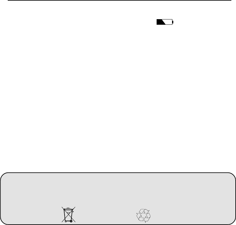
4. Changing batteries
Base station
If the flat battery symbol appears in the display (Lo Bat ) all batteries must be
changed for ones of the same type as described in Section 2.2 (Base unit, p. 8).
Always change all 4 batteries and use only high-quality alkaline cells.
Please note!
After changing the batteries, the weather station will be re-initialised, all stored
settings will be lost and will have to be re-entered.
Radio sensors
The batteries in these sensors have a service life of up to 2 years (alkaline batter-
ies). They must be changed when the display of the appropriate sensor in the base
device display does not appear for more than 24 hours and there is no general and
longer lasting interference of the radio path, which can usually be recognised by
the fact that data transmission from other, neighbouring sensors has also broken
down (see Section 5, "Faults").
The batteries are changed as described under 2.1.
Observe regulations for the disposal of batteries!
According to the German battery regulations you must return used or faulty batteries
and accumulators to us or return them to local commercial or battery collection
points. Batteries and accumulators must not be thrown away with household rubbish!

19
5. Information on fault removal
Possible faults that could impair the correct display of the transmitted readings
are:
No reception – The distance between transmitter and receiver is too great.
Reduce the distance between the transmitter and the receiver.
No reception – Dense shielding materials are positioned between the trans-
mitter and the receiver (thick walls, reinforced concrete, ...)
Find another position for the transmitter and receiver. See also chapter 6 ("Range").
Transmitter batteries are discharged.
Change batteries
Transmitter is blocked by a source of interference
(radio device, radio headset/loudspeaker)
Remove source of interference or find alternative location for transmitter and receiver.
Often the interference is of a temporary nature (radio telephony) or can be removed
very easily. If there are radio headsets, baby listening devices or similar devices
operating on 433 MHz in your house or in the neighbourhood, their turn-on time is
normally limited. Most of these devices permit change to a frequency free of inter-
ference. A measure such as this effectively cuts out interference.
A radio sensor interferes with other devices in the 433 MHz range
The transmissions from a radio sensor can interfere with other devices on the same
channel for a short period (every 3 minutes for about 100 ms).
Further information on installation and removal of interference
Under critical reception conditions the sensor test mode makes it easier to choose
the best possible location. For this purpose, the sensor concerned is put in test
mode, so that every four seconds a data telegram is transmitted.
To activate the test mode, remove the batteries from the sensors and then wait for
at least 60 seconds before putting them back in. You must then initiate synchroni-
sation mode on the base unit, also by removing and then reinserting the batteries
(Attention! All settings and collected data will then be lost!)
Rotate the weather station a little if required, and if reception is bad, locate it away
from electric motors, electrical machines, televisions, computer monitors and large
metal surfaces.
To facilitate commissioning you can initially locate the sensors in the vicinity of the
base unit (at least 2 m distance). In this way you can check the correct transmission
of data by the sensor.

20
6. Range
The free field range, i.e. the range of the line of sight contact between the transmitter
and the receiver is 100 m under optimum conditions. Walls and even reinforced
concrete can be penetrated, which does, however, reduce the range. A reduced
range can occur due to the following reasons:
·High-frequency interference of all kinds
·Built structures and vegetation of all types
·The distance of the transmitter or receiver from conductive surfaces or objects
(even to the human body or the ground) has an effect on the transmission
characteristics and therefore the range.
·Wide band interference in built up areas can reach levels that reduce the signal-
noise ratio throughout the frequency band which results in a reduced range.
·Devices with adjacent working frequencies can also influence the receiver.
·Badly shielded PCs can irradiate the receiver and limit its range.
7. Maintenance and servicing information
- Protect the basic device against dust and moisture. Never clean it with chemical
cleaning materials, use only a soft, dry cloth. Do not exert any pressure on the
display.
- The outdoor sensor must be cleaned of adhering dirt from time to time. When you
do so, check that the wind sensor can move freely and that the sensors are firmly
located on the holder.
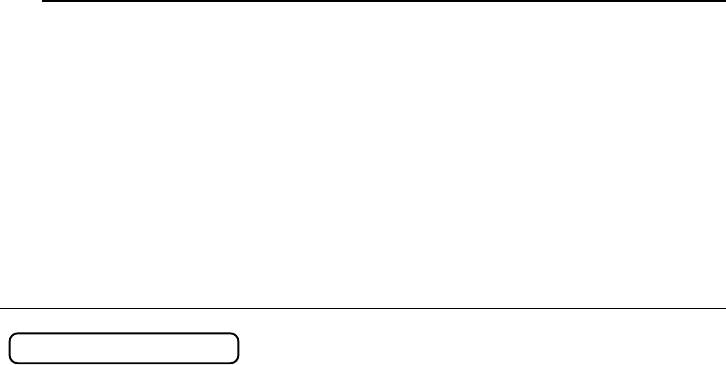
7.1. Cleaning the rainfall sensor
- Depending on the location, leaves and particles of dirt, sand, twigs etc. carried
along by the wind can get into the collector funnel of the rainfall sensor. Larger
items can clog up the opening. Sand can also accumulate in the counter rocker,
distorting the measuring results as the quantity increases.
- The rainfall sensor should therefore be cleaned from time to time, but at least
once a year.
- To do this, remove the sensor housing by turning it slightly to the left.
- The collector funnel is also removed by being turned to the left.
- The rainfall sensor is then lifted up and folded over towards the cable side so that
the counter rocker can be removed.
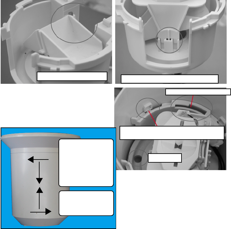
21
- Clean residue from the collector funnel, contacts, counter rocker and drain hole
at the bottom of the housing.
- Insert the counter rocker back into its bracket. The magnet of the counter rocker
must be on the side next to the cable.
- Insert the rainfall sensor into its bracket. It will automatically hold the counter
rocker firmly. The cable of the rainfall sensor and the magnet of the rocker arm
must be on the same side.
- Then put the collector funnel onto the sensor holder from above and engage it by
turning it to the right.
- Push the housing back in again from underneath and engage it in the sensor
holder by turning it to the right until it slots in. Make sure that the drain holes of
the housing and sensor holder coincide (drain hole of the housing points to the
outside).
The following pictures illustrate the disassembly/assembly process
1 - Full moon
2 - Waxing
3 - New moon
4 - Waning
Rocker correctly installed Rainfall sensor correctly installed
Drain hole
Housing correctly engaged at bottom (collec-
tion funnel removed for illustrative purposes)
Slot for collection funnel
To detach:
Turn to the left,
remove housing
from underneath,
remove collection
funnel from above
To attach:
Attach,
turn to the right

22
7.2. Calibrating the rain sensor
The rainfall measuring system is delivered ex-works with a high accuracy, so
that normally no calibration is required.
Calibration is only necessary when very high accuracy is required.
Before beginning to calibrate the rainfall measurement recorder, reset any total
rainfall quantity that may be indicated in the normal display mode back to zero
(press and hold the "RAIN" key down for about 2 s in normal display mode - when
the key is released, the total rainfall quantity will be zero).
For the exact calibration proceed as follows:
1. Over a ten-minute period slowly pour 100 ml of water into the rain sensor collector
funnel.
CAUTION!
Pouring quickly will falsify the measurement result! Slowly pour the water
into the funnel so water is at no time resting in the funnel.
2. The total amount displayed should be 6.5 l/m2.
3. If a different value is displayed, then the rocker value should be recalculated as
follows:
New rocker value = 6.5 x current rocker value
Actual value (display when filled with water)
The new rocker value must now be entered in the configuration menu (see 3.1). It is
always given in ml/rocker stroke, the units on the right are the units for the
subsequent display of rainfall!
The factory setting is 295 ml/rocker stroke.

23
8. Technical data
Measurement interval for outdoor sensors: .....................................approx. 3 min
Measuring interval for indoor sensor: ........................................................ 10 min
Transmission frequency: .................................................................... 433.92 MHz
Free field range: .................................................................................. max. 100 m
Indoor temperature range: ......................................................... 32 ˚F to +175.8 ˚F
Resolution: ................................................................................................... 0.1 °F
Accuracy: ....................................................................................................±1,5 ˚F
Outdoor temperature range (KS 300US):................................. -21 ˚F to +175,8 ˚F
Resolution: ................................................................................................... 0.1 °F
Accuracy: ....................................................................................................±1.5 ˚F
Measuring range for relative humidity (indoor/outdoor):...................... 0% - 99 %
Resolution: ....................................................................................................... 1%
Accuracy: ....................................................................................................... ±5%
Rainfall indicator: ............................................................................. 0 to 99,9 inch
Analysis interval: ...................last hour: at xx:30 hours, total for day: at 7.30 a.m.
Resolution: ............................................................................................. < 0.3 mm
Wind speed: ....................................................................................... 0 - 124 mph
Resolution: ..................................up to 100 mph: 0.1 mph; over 100 mph: 1 mph
Voltage supply:
Base station ......................................................4 x 1.5 V/LR6/Mignon/AA battery
KS 300US: ........................................................3 x 1.5 V/LR6/Mignon/AA battery
Dimensions (W x H x D) of base station: ... 160 x 220 x 35 mm (excluding stand)
9. Explanation of terms
Perceived temperature - see Wind chill
Dew point - Temperature point that is dependent on the conjunction of a specific
air pressure, a specific temperature and a specific humidity. At this temperature
humidity begins to condense, the so-called dew, the humidity condenses and
precipitates as a liquid. If the dew point for water vapour is less than 32 °C, the
condensation occurs as snow or frost.
Weather forecast - Forecast display using weather symbols, calculated from the
speed at which the air pressure rises or falls (tendency).
The speed of change of air pressure is the critical factor for the prediction of the
coming weather; the absolute value is of secondary importance. In general, it can
be said that rising air pressure indicates better weather, while falling air pressure
indicates deteriorating weather.
Wind chill equivalent temperature (perceived temperature) - A fictitious
temperature, which the human body feels under certain conditions instead of the
measured temperature, and which can be used at low temperatures (e.g. less than

24
44,6 ˚F) to say how comfortable one feels at certain temperatures and wind speeds
whilst wearing appropriate clothing. These conditions are a temperature below
91,4 °F and a wind speed higher than 9,4 mph. Wind chill is defined as the cooling
effect of uncovered skin at an assumed constant 91,4 °F skin surface temperature.
The higher the wind speed is and the lower the actual temperature, the more
noticeable is the wind chill effect.
The "perceived temperature" is roughly comparable to the so-called felt tempera-
ture, which additionally takes into account the radiation effect of the sun, light re-
fection from the clouds, the light wavelength, etc.
Wind strength table
Beaufort Wind speed mph Wind speed km/h Description
0 0 - 1 0 - 0,7 Calm
1 1 - 3 0,8 - 5,4 Slight air
2 4 - 7 5,5 - 11,9 Light breeze
3 8 - 12 12,0 - 19,4 Gentle breeze
4 13 - 18 19,5 - 28,5 Moderate breeze
5 19 - 24 28,6 - 38,7 Fresh breeze
6 25 - 31 38,8 - 49,8 Strong breeze
7 32 - 38 49,9 - 61,7 Moderate gale
8 39 - 46 61,8 - 74,6 Fresh gale
9 47 - 54 74,7 - 88,9 Strong gale
10 55 - 63 89,0 - 102,4 Whole gale
11 64 - 72 102,5 - 117,4 Storm
12 > 73 > 117,4 Hurricane
The Comfort Indicator (☺) represents the climatic conditions, for which the
following table is used (the symbol status shows the area of validity):
Temperature Humidity
20% 30% 35% 40% 45% 50% 55% 60% 65% 70%
< 64,4°F
64,4°F-67,8°F
67,9° F-71,4°F☺☺ ☺☺
71,4°F-75,0°F☺☺☺ ☺
75,1° F-78,6°F☺☺☺☺
78,7°F-82,2°F
> 82,2°F
25
It can be seen from this that, depending on the ratio of temperature to humidity,
there are clearly bounded areas, which are defined as a comfortable or an
uncomfortable climate. Hence, one finds a humidity level of 30% at a temperature
of 77 °F, for example, to be too dry (e.g. heating air) and one above 60% to be
sultry.
10. Intended usage, exclusion of liability,
safety instructions
- This weather station is intended for domestic use as an indicator of future weather.
The forecasts of this device are to be considered guidelines only and do not in
any way constitute absolutely accurate predictions.
- The manufacturer of this weather station accepts no responsibility for incorrect
measurements and the consequences arising therefrom.
- This weather station is not suitable for medical purposes or for the information of
the public.
- The components of this weather station are not toys! They contain breakable
glass and small parts. Erect all components in such a way that they are out of the
reach of children.
11. FCC Information
FCC ID: RNT-WS300US
Changes or modifications not expressly approved in writing by ELV Electronics
Limited may void the user’s authority to operate the equipment.
NOTE: This equipment has been tested and found to comply with the limits for a
Class B digital device, pursuant to Part 15 of the FCC Rules. These limits are
designed to provide reasonable protection against harmful interference in a
residential installation. This equipment generates, uses and can radiate radio
frequency energy and, if not installed and used in accordance with the
instructions, may cause harmful interference to radio communications. However,
there is no guarantee that interference will not occur in a particular installation. If
this equipment does cause harmful interference to radio or television reception,
which can be determined by turning the equipment off and on, the user is
encouraged to try to correct the interference by one or more of the following
measures:
- Reorient or relocate the receiving antenna.
- Increase the separation between the equipment and receiver.
- Connect the equipment into an outlet on a circuit different from that to
which the receiver is connected.
- Consult the dealer or an experienced radio/TV technician for help.
26
The internal antenna used for this mobile transmitter must provide a separation
distance of at least 20 cm from all persons and must not be co-located or
operating in conjunction with any other antenna or transmitter.
This device complies with Part 15 of the FCC Rules. Operation is subject to the
following two conditions:
(1) this device may not cause harmful interference, and
(2) this device must accept any interference received, including interference
that may cause undesired operation.
27
28
ELV Electronics Ltd. Hong Kong