ecom instruments 300011GR04 RFID Reader User Manual
ecom instruments GmbH RFID Reader
Contents
- 1. Annex to User manual
- 2. User manual
User manual

Datum // date
15.03.2013
Teile-Nr. // part no.
300011
Dokument-Nr. Revision //
document no. revision
300011AL11E 04
Head Module Settings
User Manual
Seite/gesamt // page/total
1 / 8
Dokument erstellt // document created
SAS387 15.03.2013
Dokument geprüft // document checked
FIH091 ,09.04.2013
User Manual: Head Module Settings
● Ablageort: I:\300011\083_Software\05 Dokumente\300011AL11E04_user_manual_head_module_settings.docx
● template no.: 0730QV06A03 ● template created: HAO006 20.01.2011 ● template checked: BEA373 20.01.2011 ● location: ISO drive ●
ecom instruments GmbH
Inhaltsverzeichnis
1 Head Module Settings .................................................................................................................... 2
1.1 Introduction ................................................................................................................................ 2
1.2 Enable Module........................................................................................................................... 3
1.3 #L|F – TLB30 ............................................................................................................................. 3
1.4 #H – UNI13 ................................................................................................................................ 4
1.5 #Q – ARE8 ................................................................................................................................ 4
1.6 #T – LID ..................................................................................................................................... 5
1.7 S# - SE955 ................................................................................................................................ 5
1.8 Wedge Data ............................................................................................................................... 6
1.9 Good Read ................................................................................................................................ 6
1.10 Version Info ............................................................................................................................. 7
2 Trigger Button Settings ................................................................................................................. 8
2.1 Map the trigger event “OEM Trigger” on a button ..................................................................... 8
Datum // date
15.03.2013
Teile-Nr. // part no.
300011
Dokument-Nr. Revision //
document no. revision
300011AL11E 04
Head Module Settings
User Manual
Seite/gesamt // page/total
2 / 8
Dokument erstellt // document created
SAS387 15.03.2013
Dokument geprüft // document checked
FIH091 ,09.04.2013
User Manual: Head Module Settings
● Ablageort: I:\300011\083_Software\05 Dokumente\300011AL11E04_user_manual_head_module_settings.docx
● template no.: 0730QV06A03 ● template created: HAO006 20.01.2011 ● template checked: BEA373 20.01.2011 ● location: ISO drive ●
ecom instruments GmbH
1 Head Module Settings
1.1 Introduction
The Head Module Settings are there for controlling the head modules. They provide the following: enable
or disable a head module (see 1.2 Enable Module) set settings for each head module (see 1.3 #L|F –
TLB30, 1.4 #H – UNI13, 1.5 #Q – ARE8 1.6 #T – LID and 1.7 S# - SE955), set a preamble/postamble for
the output data (see 1.8 Wedge Data), enable or disable the beep that should be ringing out or not after
a good read (see 1.9 Good Read), display version of the service of the head modules which is installed
on your device (see 1.10 Version Info). The Head Module Settings are located in the Intermec Settings.
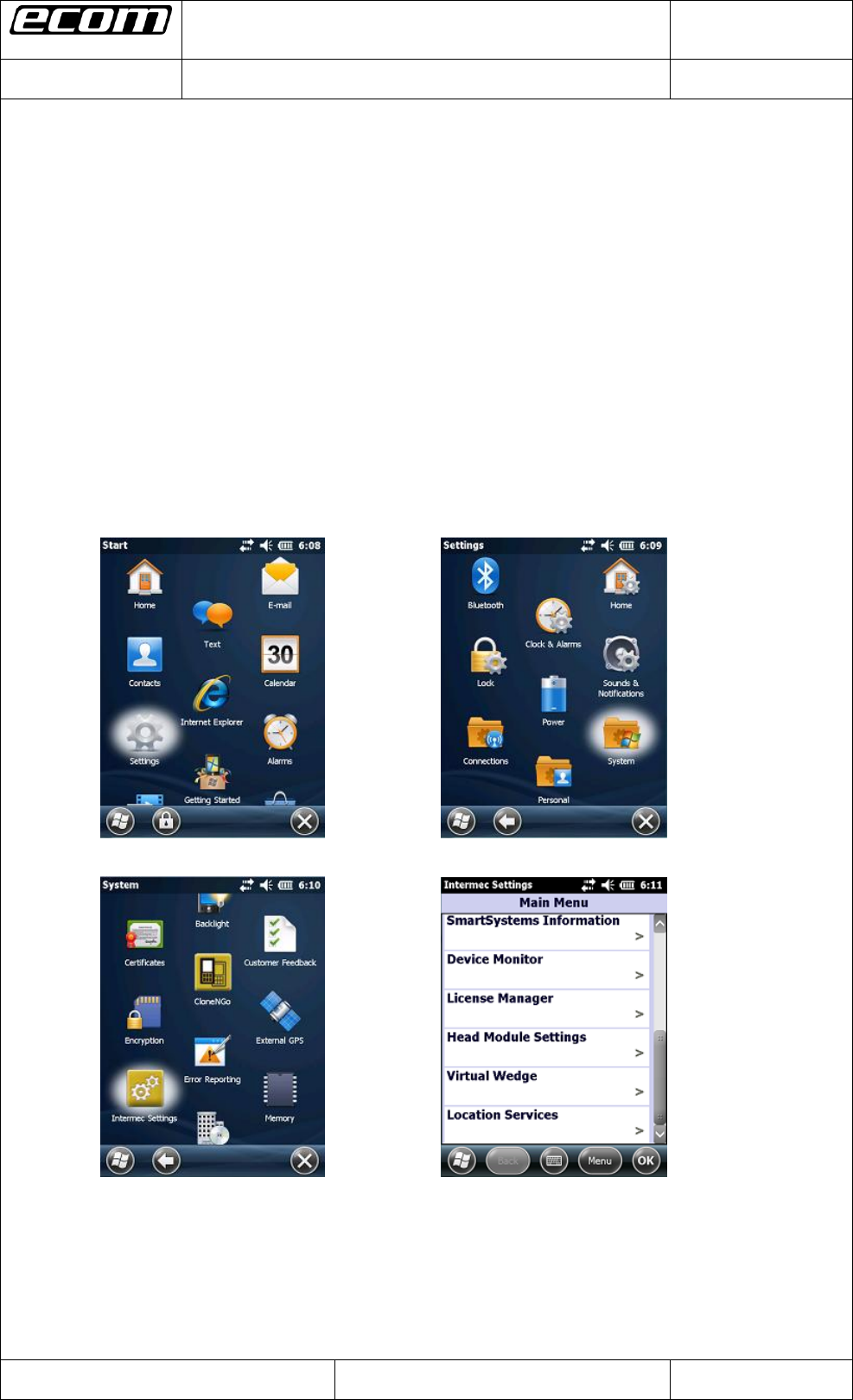
To open the Head Module Settings click on the windows icon on the main screen. Then click on Settings
->System->Intermec Settings (see Step1-3). Scroll down until “Head Module Settings” (see Step4) and
click on it. The Head Module Settings will be opened. After you have made any settings in the Head
Module Settings you can start reading with your head module by clicking the blue center button on the
keyboard of your device.
Step1 Step2
Step3 Step4
Datum // date
15.03.2013
Teile-Nr. // part no.
300011
Dokument-Nr. Revision //
document no. revision
300011AL11E 04
Head Module Settings
User Manual
Seite/gesamt // page/total
3 / 8
Dokument erstellt // document created
SAS387 15.03.2013
Dokument geprüft // document checked
FIH091 ,09.04.2013
User Manual: Head Module Settings
● Ablageort: I:\300011\083_Software\05 Dokumente\300011AL11E04_user_manual_head_module_settings.docx
● template no.: 0730QV06A03 ● template created: HAO006 20.01.2011 ● template checked: BEA373 20.01.2011 ● location: ISO drive ●
ecom instruments GmbH
1.2 Enable Module
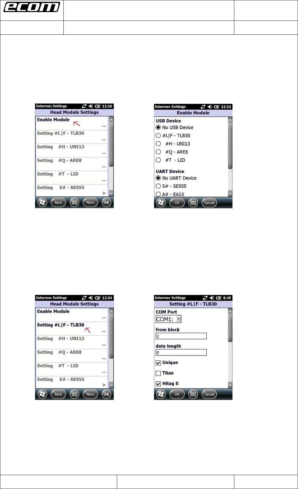
There is a possibility in the Head Module Settings called “Enable Module” where you can enable or
disable a head module. Open the Head Module Settings and choose “Enable Module” (see Pic1). In the
next window (see Pic2) you can choose one of a USB device (for example the LF reader) or one of a
UART device (for example the SE955 scanner). Click on the OK button to save your choice.
Pic1: Head Module Settings Pic2: Enable Module
1.3 #L|F – TLB30
After you have enabled the LF reader through selecting it in the “Enable Module” section in the Head
Module Settings (see 1.2 Enable Module) you are now able to change some settings for the LF reader.
Open the Head Module Settings and choose “Setting #L|F – TLB30” (see Pic3). In the next window (see
Pic4) you can make any changes you want to do for the LF reader. Click on the OK button to save your
changes.
Pic3: Head Module Settings after
enabling the LF reader Pic4: LF reader settings
Datum // date
15.03.2013
Teile-Nr. // part no.
300011
Dokument-Nr. Revision //
document no. revision
300011AL11E 04
Head Module Settings
User Manual
Seite/gesamt // page/total
4 / 8
Dokument erstellt // document created
SAS387 15.03.2013
Dokument geprüft // document checked
FIH091 ,09.04.2013
User Manual: Head Module Settings
● Ablageort: I:\300011\083_Software\05 Dokumente\300011AL11E04_user_manual_head_module_settings.docx
● template no.: 0730QV06A03 ● template created: HAO006 20.01.2011 ● template checked: BEA373 20.01.2011 ● location: ISO drive ●
ecom instruments GmbH
1.4 #H – UNI13
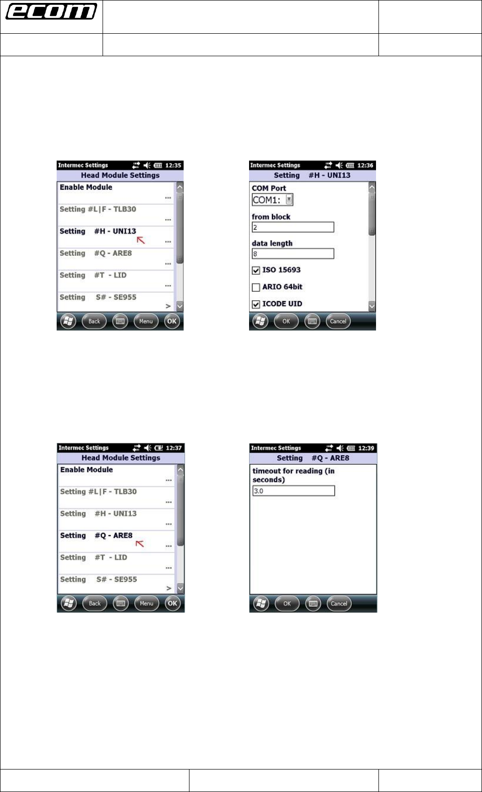
To make some changes for the HF reader, enable the reader in the “Enable Module” section in the Head
Module Settings. Then click on “Setting #H – UNI13” (see Pic5). In the next window (see Pic6) make
your changes you want to do for the HF reader and save them by clicking the OK button.
Pic5: Head Module Settings after
enabling the HF reader Pic6: HF reader settings
1.5 #Q – ARE8
To make some changes for the ARE Trovan reader, enable the reader in the “Enable Module” section in
the Head Module Settings. Then click on “Setting #Q – ARE8” (see Pic7). In the next window (see Pic8)
make your changes you want to do for the ARE Trovan reader and save them by clicking the OK button.
Pic7: Head Module Settings after
enabling the ARE Trovan reader Pic8: ARE Trovan reader settings
Datum // date
15.03.2013
Teile-Nr. // part no.
300011
Dokument-Nr. Revision //
document no. revision
300011AL11E 04
Head Module Settings
User Manual
Seite/gesamt // page/total
5 / 8
Dokument erstellt // document created
SAS387 15.03.2013
Dokument geprüft // document checked
FIH091 ,09.04.2013
User Manual: Head Module Settings
● Ablageort: I:\300011\083_Software\05 Dokumente\300011AL11E04_user_manual_head_module_settings.docx
● template no.: 0730QV06A03 ● template created: HAO006 20.01.2011 ● template checked: BEA373 20.01.2011 ● location: ISO drive ●
ecom instruments GmbH
1.6 #T – LID
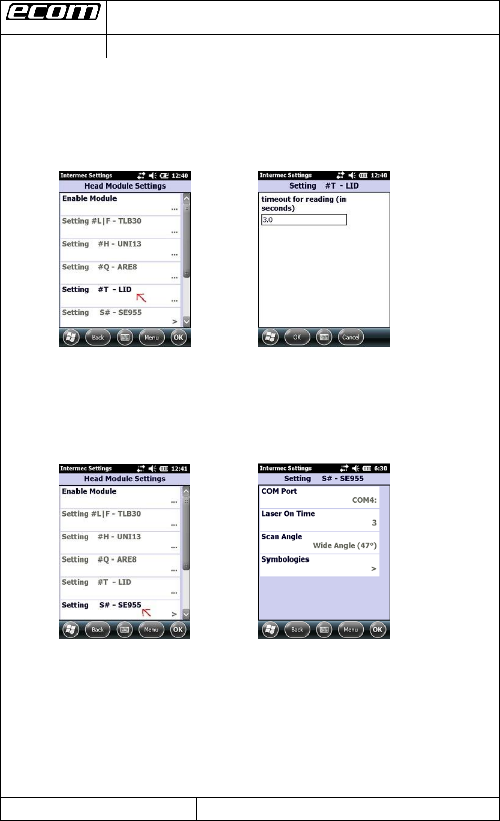
To make some changes for the LID Trovan reader, enable the reader in the „Enable Module“ section in
the Head Module Settings. Then click on “Setting #T - LID“ (see Pic9). In the next window (see Pic10)
make your changes you want to do for the LID Trovan reader and save them by clicking the OK button.
Pic9: Head Module Settings after
enabling the LID Trovan reader Pic10: LID Trovan reader settings
1.7 S# - SE955
To make some changes for the SE955 scanner, enable the scanner in the “Enable Module” section in the
Head Module Settings. Then click on “Setting S# – SE955” (see Pic11). In the next window (see Pic12)
make your changes you want to do for the SE955 scanner and save them by clicking the OK button.
Pic11: Head Module Settings after
enabling the SE955 scanner Pic12: SE955 scanner settings
Datum // date
15.03.2013
Teile-Nr. // part no.
300011
Dokument-Nr. Revision //
document no. revision
300011AL11E 04
Head Module Settings
User Manual
Seite/gesamt // page/total
6 / 8
Dokument erstellt // document created
SAS387 15.03.2013
Dokument geprüft // document checked
FIH091 ,09.04.2013
User Manual: Head Module Settings
● Ablageort: I:\300011\083_Software\05 Dokumente\300011AL11E04_user_manual_head_module_settings.docx
● template no.: 0730QV06A03 ● template created: HAO006 20.01.2011 ● template checked: BEA373 20.01.2011 ● location: ISO drive ●
ecom instruments GmbH
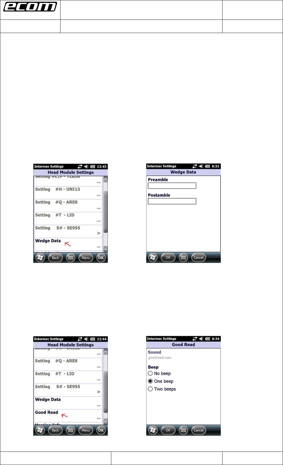
1.8 Wedge Data
To set a preamble or postamble for the data which is read from a head module, open the Head Module
Settings and click on “Wedge Data” (see Pic13). In the next window (see Pic14) set a preamble or
postamble by filling out the corresponding text field and save your settings by clicking the OK button.
Note: You can also set an escape literal for preamble or postamble. The following escape literals are
allowed: \a, \b, \t, \n, \v, \f, \r. A second special feature for preamble/postamble is to set one of the
following codes:
#TAB (sends a tab)
#SPACE (sends a space)
#ENTER (sends an enter)
#xxx (xxx stands for a decimal number between 000 and 127; you can set any ASCII character
for preamble/postamble by using the decimal code of the character -> for example if you set #013
as preamble or postamble a carriage return will be sent)
Pic13: Head Module Settings Pic14: Preamble/Postamble
1.9 Good Read
The Head Module Settings provide an option to set a beep for ringing out after a good read. To set this,
open the Head Module Settings and click on “Good Read” (see Pic15). In the next window (see Pic16)
you have the opportunity to set “no beep”, “one beep” or “two beeps”. Save your setting by clicking the
OK button.
Pic15: Head Module Settings Pic16: Beep options
Datum // date
15.03.2013
Teile-Nr. // part no.
300011
Dokument-Nr. Revision //
document no. revision
300011AL11E 04
Head Module Settings
User Manual
Seite/gesamt // page/total
7 / 8
Dokument erstellt // document created
SAS387 15.03.2013
Dokument geprüft // document checked
FIH091 ,09.04.2013
User Manual: Head Module Settings
● Ablageort: I:\300011\083_Software\05 Dokumente\300011AL11E04_user_manual_head_module_settings.docx
● template no.: 0730QV06A03 ● template created: HAO006 20.01.2011 ● template checked: BEA373 20.01.2011 ● location: ISO drive ●
ecom instruments GmbH
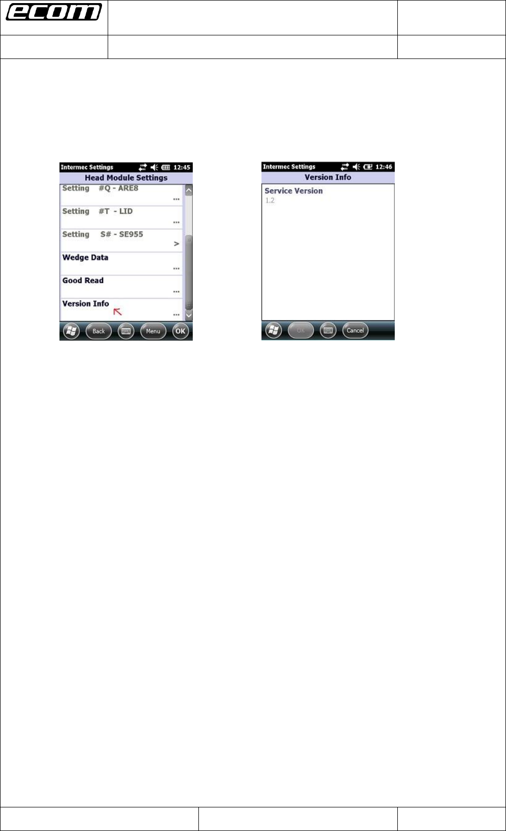
1.10 Version Info
Last point in the Head Module Settings gives you the opportunity to get information about the version of
the service of the head modules which is installed on your device. Open the Head Module Settings and
click on “Version Info” (see Pic17). In the next window you can see the version of the service (see Pic18).
Pic17: Head Module Settings Pic18: Service Version
Datum // date
15.03.2013
Teile-Nr. // part no.
300011
Dokument-Nr. Revision //
document no. revision
300011AL11E 04
Head Module Settings
User Manual
Seite/gesamt // page/total
8 / 8
Dokument erstellt // document created
SAS387 15.03.2013
Dokument geprüft // document checked
FIH091 ,09.04.2013
User Manual: Head Module Settings
● Ablageort: I:\300011\083_Software\05 Dokumente\300011AL11E04_user_manual_head_module_settings.docx
● template no.: 0730QV06A03 ● template created: HAO006 20.01.2011 ● template checked: BEA373 20.01.2011 ● location: ISO drive ●
ecom instruments GmbH
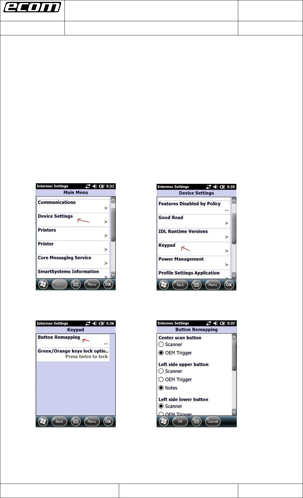
2 Trigger Button Settings
2.1 Map the trigger event “OEM Trigger” on a button
This is necessary to start reading with a head module. There is an event named “OEM Trigger” which
is used in the service of the head modules to start reading with a head module. This event is mapped
on the center scan button by default. You have five opportunities to map this event on a button:
on the center scan button, on the left side upper button, on the left side lower button, on the right side
upper button and on the right side lower button.
To map a button on the event open the Intermec Settings. Therefore you have to click on the
windows icon on the main screen.
In the next step you have to click on Settings -> System -> Intermec Settings.
To map the event on a button click on Device Settings -> Keypad -> Button Remapping (see Pic19-
Pic21) in the Intermec Settings. In the next window you can map the “OEM Trigger” event on a
button which you want to use to start reading with a head module (see Pic22).
Pic19: Intermec Settings Pic20: Device Settings
Pic22: Button Remapping
(“OEM Trigger” is mapped on the
Pic21: Keypad center scan button by default)