elero Antriebstechnik RT915S Tubular motors with electronic limit switch with transceiver at 915MHz User Manual 138186606 RolTop 915 120V 60Hz BA US CA 0513 indd
elero GmbH Antriebstechnik Tubular motors with electronic limit switch with transceiver at 915MHz 138186606 RolTop 915 120V 60Hz BA US CA 0513 indd
User Manual

Roller shutter drive RolTop-915
120 V / 60 Hz
138186606_US+CA_0513
Roller shutter drive RolTop-915
120V / 60Hz
1 Operating and installation
instructions
Please keep these operating instructions for later use and
have them available during the complete service life of the
product!
The German version of these operating instructions is
the original version.
All foreign language documents are translations of the
original version.
All rights reserved with regard to patent claim or submission
of design or utility patent.
2 General information
The structure of these operating instructions is based on
the service life phases of the electrical drive (subsequently
referred to as product).
The manufacturer reserves the right to make changes to the
technical data included in these operating instructions. The-
se may deviate from the respective model of the product
while the factual information are generally not changed and
are not losing their validity. The current state-of-the-art can
be obtained from the manufacturer at all times. Potential
claims cannot be asserted. Deviations from text and pictori-
al statements are not possible and depending on the tech-
nical development, setup and accessories of the product.
Deviating information on special models are included by the
manufacturer in the sales documentation. Other information
shall remain unaffected by this.
Table of contents
1 Operating and installation
instructions 1
2 General information 1
2.1 Standards and guidelines 2
2.2 Intended use 2
2.3 Foreseeable misuse 2
2.4 Warranty and liability 2
2.5 Customer service of the manufacturer 2
3 Safety 2
3.1 General safety instructions 2
3.2 Layout of safety instructions 2
3.3 General safety principles 3
3.4 General obligations of the operator 3
3.5 General requirements on personnel 3
3.6 Safety instructions on technical condition 4
3.7 Safety instructions on transport,
assembly and installation 4
3.8 Safety instructions on operation 4
3.9 Safety instructions on electrical installation 4
4 Product description 4
5 Installation 5
5.1 Mechanical mounting 5
5.2 Electrical connection 6
5.3 Connection example, RolTop-915 120 V / 60 Hz 6
5.4 Parallel connection 6
5.5 Commissioning 6
5.5.1 Installation cable connection 6
5.5.2 Wireless connection (transmitter operation) 7
5.6 End position and relief settings 7
5.6.1 Relief function for end position(s) 7
5.6.2 Relief function at the upper stop 7
5.6.3 Relief function at the lower stop 7
5.6.4 Changing / deleting of end positions
and deleting the relief function 7
5.6.5 Programming or deleting additional
fabric positions 7
5.6.6 Four options for end position settings 7
5.6.7 Option A: Upper and lower end position
freely confi gurable 8
5.6.8 Option B:
Fixed upper end position,
lower end position freely confi gurable 8
5.6.9 Option C:
Fixed upper and lower end position 8
5.6.10 Option D: Upper end position freely confi gurable,
fi xed lower end position 8
5.7 Transmitter programming 9
5.8 Programming additional transmitters(s) 9
5.9 Technical data 9
6 Troubleshooting 9
7 Servicing 9
8 Cleaning 9
9 Repair 10
10 Address 10
11 Disposal / scrapping 10
12 EC Declaration of Conformity 10
13 US: Addendum to the manual
UL approval 10
14 CA: Addendum au manuel
Homologation UL 10
• Incorrect installation, commissioning or operation of the
product
• Structural changes to the product without the written
approval of the manufacturer
• Operating the product with incorrectly installed connec-
tions, defective safety equipment or with not properly
installed safety and protective equipment
• Failure to observe the safety regulations and instructions
included in these operating instructions
• Non-compliance with the specifi ed technical data
2.5 Customer service of the manufacturer
In case of a defect, the product may only be repaired by
the manufacturer. Please refer to section „Address“ for the
return address of the customer service.
If you did not acquire the product directly from elero, please
contact your supplier.
3 Safety
3.1 General safety instructions
These operation and installation instructions include all
safety instructions for prevention and avoiding of dangers
during handling of the product over its entire life cycles.
Compliance with all specifi ed safety instructions ensures
safe operation of the product.
3.2 Layout of safety instructions
The safety instructions in this document are marked by dan-
ger signs and safety symbols and are designed according
to the SAFE principle. They include information on type and
source of the danger as well as on possible consequences
and on prevention of the danger.
The following table defi nes the design and description of the
levels of danger with potential physical injuries as they are
used in these operating instructions.
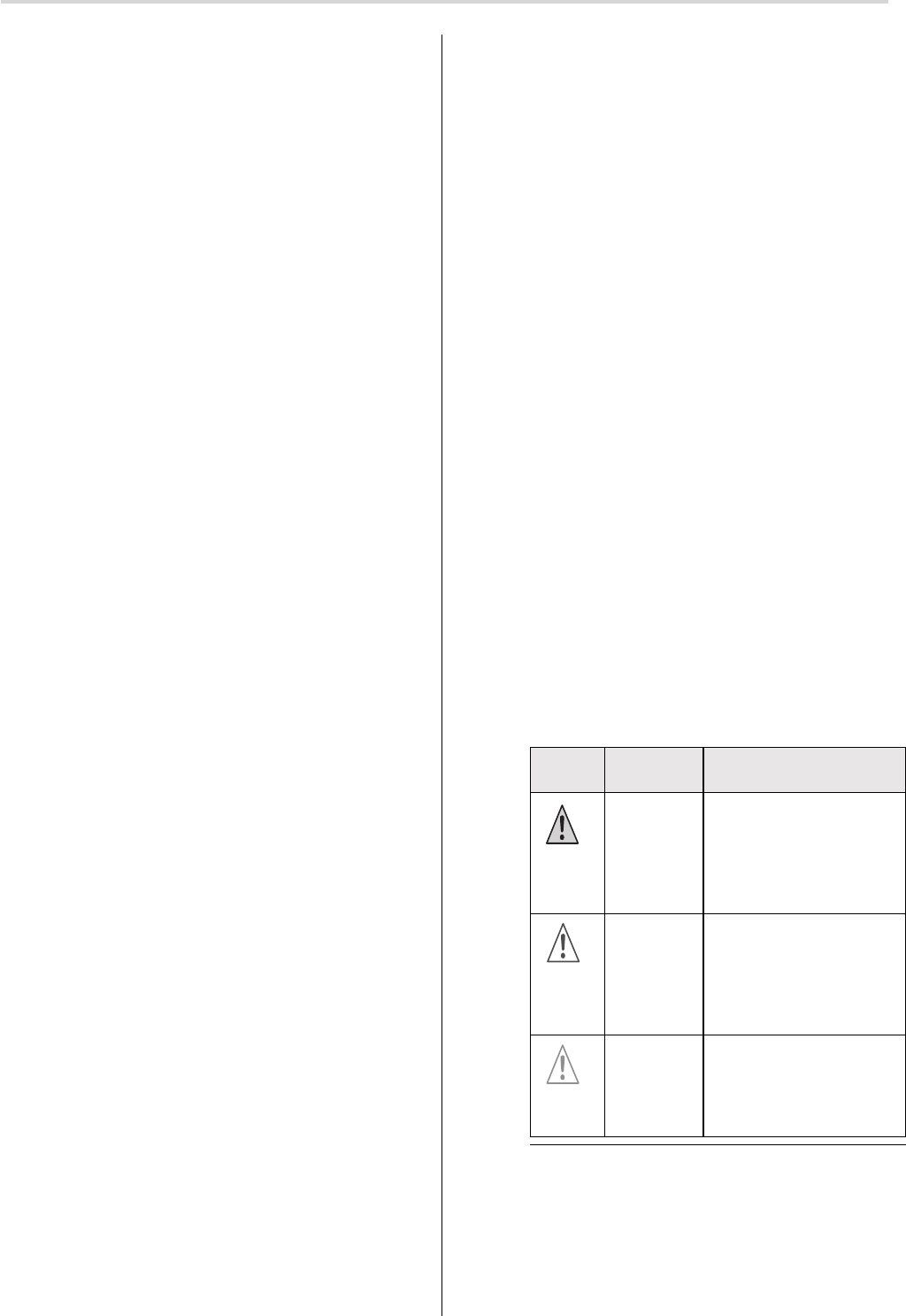
Symbol Signal
word
Description
DANGER Warns of a potential ac-
cident with if instructions
are not complied with
leading to life-threatening,
irreversible injuries or
death.
WARNING Warns of a potential ac-
cident with if instructions
are not complied with lea-
ding to severe, potentially
life-threatening, irreversib-
le injuries or death.
CAUTION Warns of a potential ac-
cident with if instructions
are not complied with
leading to light, reversible
injuries.
Fig. 1 Notation of personal injury
The following table describes symbols used in these ope-
rating instructions for illustration of dangerous situations
in connection with the respective symbol for the level of
danger.
2 | US+CA © elero GmbH
Standards and guidelines | Safety
2.1 Standards and guidelines
During system design, basic safety and health requirements
of applicable laws, standards and guidelines were obser-
ved. The safety is confi rmed by means of the Declaration
of Conformity (refer to „EC Declaration of Conformity“). All
safety information in these operating instructions are based
on currently applicable laws and regulations in Germany.
All information in the operating instructions must be obser-
ved at all times. Apart from the safety instructions in these
operating instructions, applicable local regulations on pre-
vention of accidents, environmental protection and occupa-
tional safety must be observed. Regulations and standards
for safety assessment can be found in the EC Declaration
of Conformity.
2.2 Intended use
This product is intended for use in facade construction for
driving electrical sun protection devices.
Decisive for the determination of the drive system is the
elero drive computation program (http://elero.com/
en;service;drive-computation-program.htm).
Other applications must be approved in advance by the ma-
nufacturer elero GmbH Antriebstechnik (refer to „Address“).
The operator alone is liable for all damage due to improper
use of the product. The manufacturer does not assume any
liability for personal injuries and property damage due to
misuse or procedural violations by improper use or commis-
sioning.
The product may only be operated by trained and autho-
rized personnel under observation of all safety instructions.
Safe and correct operation and operational safety of the
product is subject to operation according to its intended use
according to the provisions of these operating and installati-
on instructions.
The receiver must only be connected with equipment and
systems approved by the manufacturer. The operator is not
protected against interference by other wireless systems
and terminal equipment (e. g. also by means of wireless
systems) that are properly operated within the same fre-
quency range. Wireless systems must not be operated in
areas with increased interference factor (e. g. hospitals,
airports etc.). Remote control is only allowed for equipment
and systems if malfunctions in hand/wall transmitters or
receivers do not lead to damage for personnel, animals or
property or if this risk is covered by other safety installati-
ons.
The intended use includes observance and compliance of
all safety instructions included in these operating instruc-
tions and all applicable regulations by the trade association
and applicable laws for environmental protection. The inten-
ded use also includes compliance of all company regulati-
ons included in these operating and installation instructions.
2.3 Foreseeable misuse
Foreseeable misuse includes operating the product not in
accordance with the intended use approved by the manu-
facturer elero GmbH Antriebstechnik (refer to „Address“).
2.4 Warranty and liability
Generally, the general terms and conditions of sale and
delivery of the manufacturer elero GmbH Antriebstechnik
(refer to „Address“) apply. The terms and conditions of sale
and delivery are part of the sales documentation and are
handed over to the operator on delivery. Liability claims for
personal and property damage are excluded if such dama-
ge is due to one or several of the following causes:
• Opening the product by the customer
• Improper use of the product
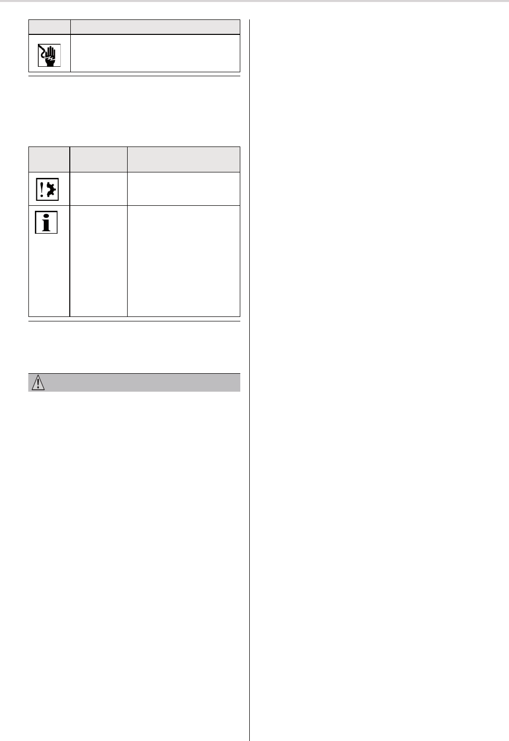
Symbol Description
Danger due to voltage, electrical shock:
This symbol indicates dangers due to
electricity.
Fig. 2 Notation of a specifi c danger
The following table defi nes the illustration and description
of situations in these operating instructions that may lead
to damage to the product or indicates facts, conditions, tips
and information.
Symbol Signal
word
Description
NOTE This symbol warns of po-
tential property damage.
IMPOR-
TANT
This symbol indicates
important facts and con-
ditions as well as further
information in these
operating and installation
instructions. Additionally,
it refers to certain inst-
ructions giving additional
information or helping you
to perform a task.
Fig. 3 Notation of property damage and additional informa-
tion
The following example illustrates the general layout of a
safety instruction:
SIGNAL WORD
Type and source of danger
Description of the type and source of danger
►Measures for prevention of the danger.
3.3 General safety principles
The product was designed according to the state-of-the-art
and recognized safety-related rules and is safe for opera-
tion. During product design, basic safety and health requi-
rements of applicable laws, standards and guidelines were
observed. The safety of the product is confi rmed by the EC
Declaration of Conformity.
All information on safety refer to currently applicable direc-
tives of the European Union. Operators in other countries
must ensure that applicable local laws and regulations are
observed.
Apart from the safety instructions in these operating inst-
ructions, generally applicable regulations on prevention of
accidents and environmental protection must be observed.
The product must only be used in technically fl awless condi-
tion and for proper safety-conscious and risk-conscious use
while observing the operating instructions. The product is
designed for operation according to section „intended use“.
Operation of the product not according to its intended use
may lead to danger for life and limb of the user and third
parties or cause damage to the machine and other proper-
ties. The manufacturer must be immediately and directly in-
formed on accidents or near misses during operation of the
product that caused or may have caused personal injuries
and or damage to the working environment.
All safety instructions in the operating instructions and on
the product must be observed. Additionally to observing
these safety instructions, the operator must ensure that
all national and international regulations applicable in the
country of operation and other binding regulations on ope-
rational safety, prevention of accidents and environmental
protection are complied with. All work on the product must
only performed by trained, safety-related instructed and
authorized personnel.
Appropriately qualifi ed personnel must observe all appli-
cable standards and regulations in the country of installation
and inform the customer on the operating and maintenance
requirements of the product.
3.4 General obligations of the operator
The operator is obliged to only operate the product in
technically fl awless and operationally safe condition. The
operator must ensure that apart from the safety instruc-
tions in the operating instructions, generally applicable
regulations on safety and prevention of accidents, the
provisions of DIN VDE 0100 as well as the regulations
on environmental protection of the respective country of
operation are observed and complied with.
The operator is obliged to ensure that all work on the pro-
duct is carried out by trained and safety-related instructed
and authorized personnel.
Ultimately responsible for accident-free operation is the
operator of the product or the personnel authorized by
him.
The operator is responsible for compliance of the tech-
nical specifi cations particularly the statistic and dynamic
load limits.
Non-compliance with static load limits may lead to
loss of the supporting or holding function.
With respect to the intended use, the operator must ensu-
re dry, not too warm ambient conditions (building condi-
tions) under the infl uence of radial heat. Deviations must
be approved by the manufacturer.
3.5 General requirements on personnel
Each person commissioned to work with the product
must have read and understood the entire operating
instructions prior to carrying out the respective work. This
does also apply if the person has already worked with
this kind of product or was trained on it.
Before start of all work, the personnel has to be made
aware of all dangers in connection with working on the
product.
All personnel commissioned to work with the product
must have no physical limitations temporarily or perma-
nently infl uencing their attention or good judgment (e. g.
by fatigue).
Handling the product or any assembly, disassembly and
cleaning by minors or under the infl uence of alcohol,
drugs or medication is not permitted.
Personnel must wear appropriate personal protective
equipment according to the work to be carried out and
the present work environment.
Children must not play with fi xed control panels. Keep
remote controls away from children.
Observe moving roller shutters and keep persons on a
distance until the shutter has properly closed.
© elero GmbH US+CA | 3
Safety

3.9 Safety instructions on electrical installation
Work on the electric system of the used equipment must
only be carried out by authorized electricians according to
applicable rules and regulations by the trade association,
particularly the provisions of DIN VDE 0100. Additionally,
the national legal regulations of the respective country of
operation must be observed.
In case of defects like loose connections or defective or
damaged cables on the system, the product must not put
into operation.
Prior to any inspection, installation or disassembly work,
the system (blinds, shutter) must be disconnected from
the voltage.
All electrical connections, safety equipment, safeguards
etc. must be properly installed, connected and grounded.
The power connection must be designed according to the
information in the electrical circuit diagram (type and level
of voltage).
One circuit breaker is suffi cient to disconnect the system
from the mains supply (if only one phase and neutral is
used).
If one fi xed (stationary installed) drive system is not
equipped with a mains cable with plug or other means
of disconnection from the mains supply with a contact
opening width according to the provisions of overvoltage
category II (according to IEC 60664-1) for full disconnect,
an isolating device of this kind must be installed into the
fi xed electrical installation according to the installation
regulations.
Mains connection cables for drive systems with rubber
hose cables (code 60245 IEC 53) must always be repla-
ced by cables of the same type.
The following applies for drive systems with access to
unprotected, movable parts after installation: Movable
parts of the drive system must be installed at least 2.5 m
above the ground (or another level providing access to
the drive system).
4 Product description
The RolTop-915 is a wireless-controlled electromechanical
tubular motor drive. During operation it carries out radial
movements.
Commissioning of the RolTop-915 with elero installation
cable or transmitter for confi guration of various functions.
Fabric protection system with retraction
Fabric relief function (Fabric protection system)
Relief function and retraction for fabric protection are only
active in wireless operation.
• The values for your RolTop-915 model can be found on
the name plate.
• Depending on torque and size, the different models of the
RolTop-915 are equipped with different types of braking
systems. This may lead to different operating properties
e. g. when approaching an end position.
4 | US+CA © elero GmbH
Safety | Product description
3.6 Safety instructions on technical condition
Prior to installation the product must be checked for
damage and proper condition.
The operator is obliged to only operate the product in
technically fl awless and operationally safe condition. The
technical condition must comply with statutory require-
ments applicable at the date of manufacturing stated on
the name plate.
If dangers for personnel or changes in the operational
behavior are identifi ed, the product must be put out of
operation immediately and the operator must be informed
on the incident.
Without approval by the manufacturer, no modifi cation,
extensions or alterations must be carried out on the
product.
The system must be regularly checked for imbalance or
signs of wear or damaged cables and springs (if appli-
cable).
3.7 Safety instructions on transport,
assembly and installation
In general, the respective transport company is responsible
for transporting the product. The following safety require-
ments must be observed during transport, assembly and
installation of the product:
During transport, the product must be secured according
to the regulations of the used means of transport.
For transport, only hoisting equipment and suspension
gear must be used that are appropriately dimensioned
for safely handling the forces occurring during loading,
unloading and assembly of the product.
Only points defi ned for hoisting or suspension at the
pallet and the product must be used for hoisting or sus-
pension.
If work must be carried out under suspended parts or
working equipment, these must be secured against falling
by suitable means. It must be ensured by suitable hois-
ting equipment that loads drift unintentionally, fall or get
unhooked unsupervised.
Standing under suspended loads is forbidden.
During loading with hoisting equipment, a safety helmet
must be worn.
Assembly and installation must generally only be carried
out by trained and suitably instructed specialists.
The rated torque and the rated operating time must be
suitable for the properties of the driven component („fa-
bric“).
Decisive for the determination of the drive system is the
drive computation program of the manufacturer.
The smallest internal tube diameter for the winding shaft
is 36 mm for RolTop-915 type S, 47 mm for RolTop-915
type M and 58 mm for RolTop-915 type L.
Access to the drive system must be ensured by a freely
accessible appropriately sized inspection fl ap that can
easily be opened.
3.8 Safety instructions on operation
Before initial commissioning, the operator is obliged to
inspect the product for safe and proper operation.
Inspections must also be carried out during operation of
the product in regular intervals defi ned by the operator.
5 Installation
CAUTION
Risk of injury due to hot surfaces.
The drive system gets hot during operation, therefore the
housing may be hot. Risk of skin burns.
►Wear personal protective equipment (protective gloves).
Due to potential material defects, a broken gear unit, drive
or coupling defect may cause injuries from impacts or
shocks.
►For design of the system, suitable materials were used
and a sampling test in form of a double load test accor-
ding to DIN EN 60335-2-97 was carried out.
Risk of injury from impacts or shocks due to incorrectly
installed or not properly engaged motor bearings. Risk due
to insufficient stability and stored energy (gravity).
►Selection of motor bearings according to torque specifi -
cations.
►The drive system must be secured with all provided
safety equipment.
►Inspection for proper engagement on the motor bearing
and correct screw tightening torques.
WARNING
Risk of injury due to electricity.
Risk of electric shock.
►Electrical work must only be carried out by authorized
electricians.
Risk of injury due to electricity.
Potential risk from parts that have become live due to a
malfunction.
►The electrical connection including wiring is described in
the operating and installation instructions.
CAUTION
Risk of injury due to malfunctions due to incorrect installa-
tion.
Excessive winding of the drive system leads to possible
destruction of system parts.
►For safe operation, end positions must be set / program-
med.
►Training courses by the manufacturer for specialized
companies.
NOTE
Power supply failure, braking of machine components and
other defects.
►For safe operation, the system must be properly installed
and the end positions must be set on commissioning.
Damage to the RolTop-915 by humidity ingress.
►On protection class IP44 systems, all cables or plugs
must be protected against ingress of humidity. This ac-
tion must be taken immediately after removing the Rol-
Top-915 from its original packaging.
►The drive system must be installed in a position safe from
rain.
Important
On delivery (factory settings), the RolTop-915 is in commis-
sioning mode.
►It is necessary to set the end positions
(refer to section 5.6).
Optimum use of the wireless signal.
►Position the antenna as freely as possible and reposition
it in case of bad reception.
►Do not bend, shorten or extent the antenna.
►Observe the minimum distance between two wireless
drive systems of 15 cm.
5.1 Mechanical mounting
Important preliminary consideration:
The working space around the installed drive system is
often limited. Therefore, get an overview of the implementa-
tion of the electrical connection (refer to section 5.2) prior to
the mechanical installation and carry out respective chan-
ges, if necessary.
NOTE
Damage to electrical lines by pressure or tensile loads.
►All electrical lines must be laid safe from pressure or
tensile loads.
►Observe the bending radius of the cables (at least 50
mm).
►Lay connection cables in a loop downwards to prevent
water from running into the system.
Damage to the drive system by impact loads.
►Always slide the drive system onto the shaft. Never ham-
mer onto the shaft or the drive system!
►Never drop the drive system!
Damage to or destruction of the drive system by drilling.
►Never drill into the drive system!
Important
Attach the RolTop-915 only to the provided mounting ele-
ments.
Firmly mounted control units must be visible attached.
• The fabric must be mounted on the winding shaft.
• The profi le tube must have suffi cient clearance to the
motor tube.
• Make sure there is suffi cient axial play (1 - 2 mm).
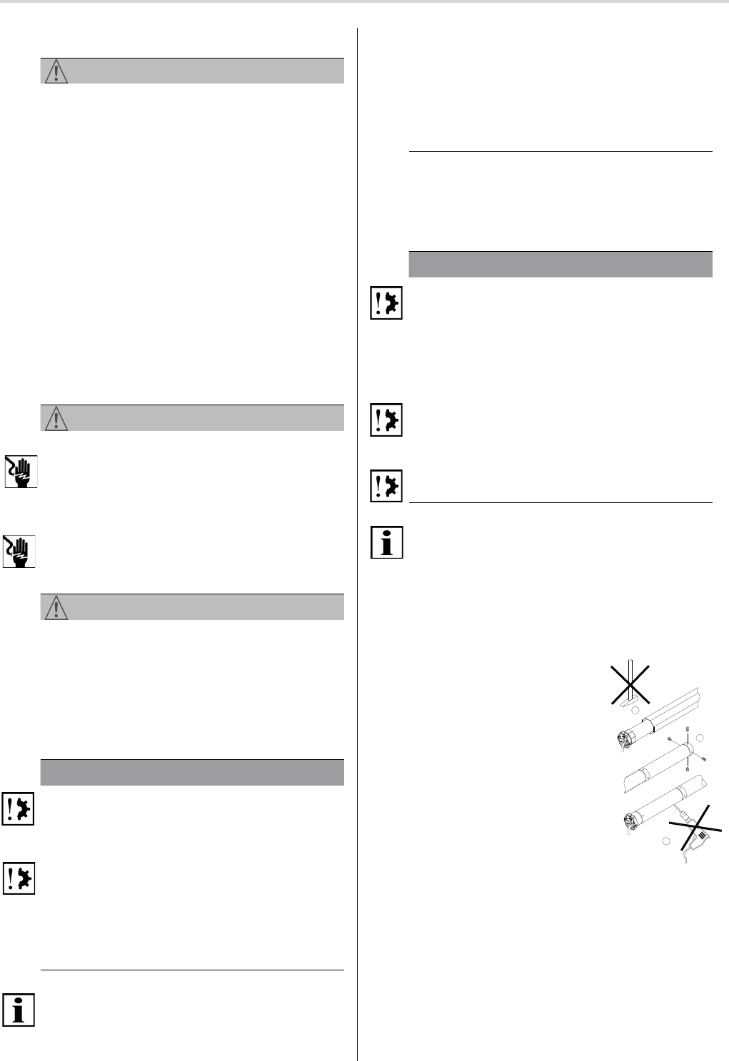
Installation in profi le tubes
Ⓐ Push the drive with suitable adapter
and driving collar into the profile tube.
Protect the motor cable in order to
avoid damage from the driven com-
ponent.
Ⓑ Secure the counterbearings to pre-
vent axial movement, e. g. screw or
rivet on shaft carrier.
Axially secure the drive in the bea-
ring!
Ⓒ Attach the fabric to the shaft!
B
A
C
© elero GmbH US+CA | 5
Installation | Mechanical mounting
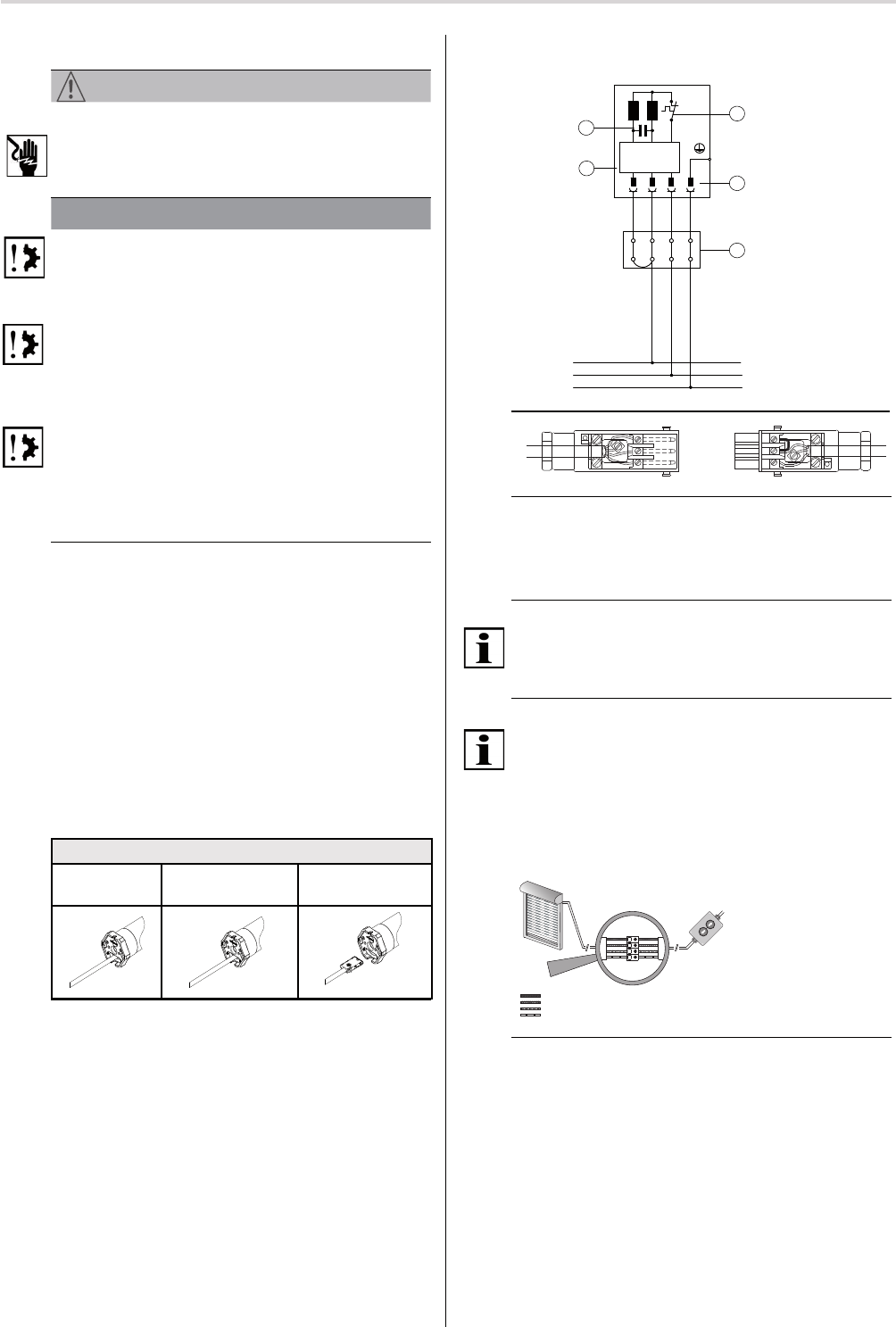
5.3 Connection example, RolTop-915 120 V / 60 Hz
N
PE
L1
sw
br
bl
gr/ge
3
2
1
Fig. 5 Circuit diagram RolTop-915 120 V / 60 Hz and
Wiring when using a Hirschmann plug connection
STAS-3 (with bridge)
5.4 Parallel connection
Important
You can connect several RolTop-915 systems in parallel. To
do so, please observe the maximum control capacity.
5.5 Commissioning
Important
On delivery, the drive system is set to commissioning mode.
►It is necessary to set the end positions with the elero
installation cable (refer to fi g. 6) or a elero wand/hand
transmitter (refer to fi g. 7).
►Connecting the installation cable is only for commissio-
ning of the drive system and for confi guration.
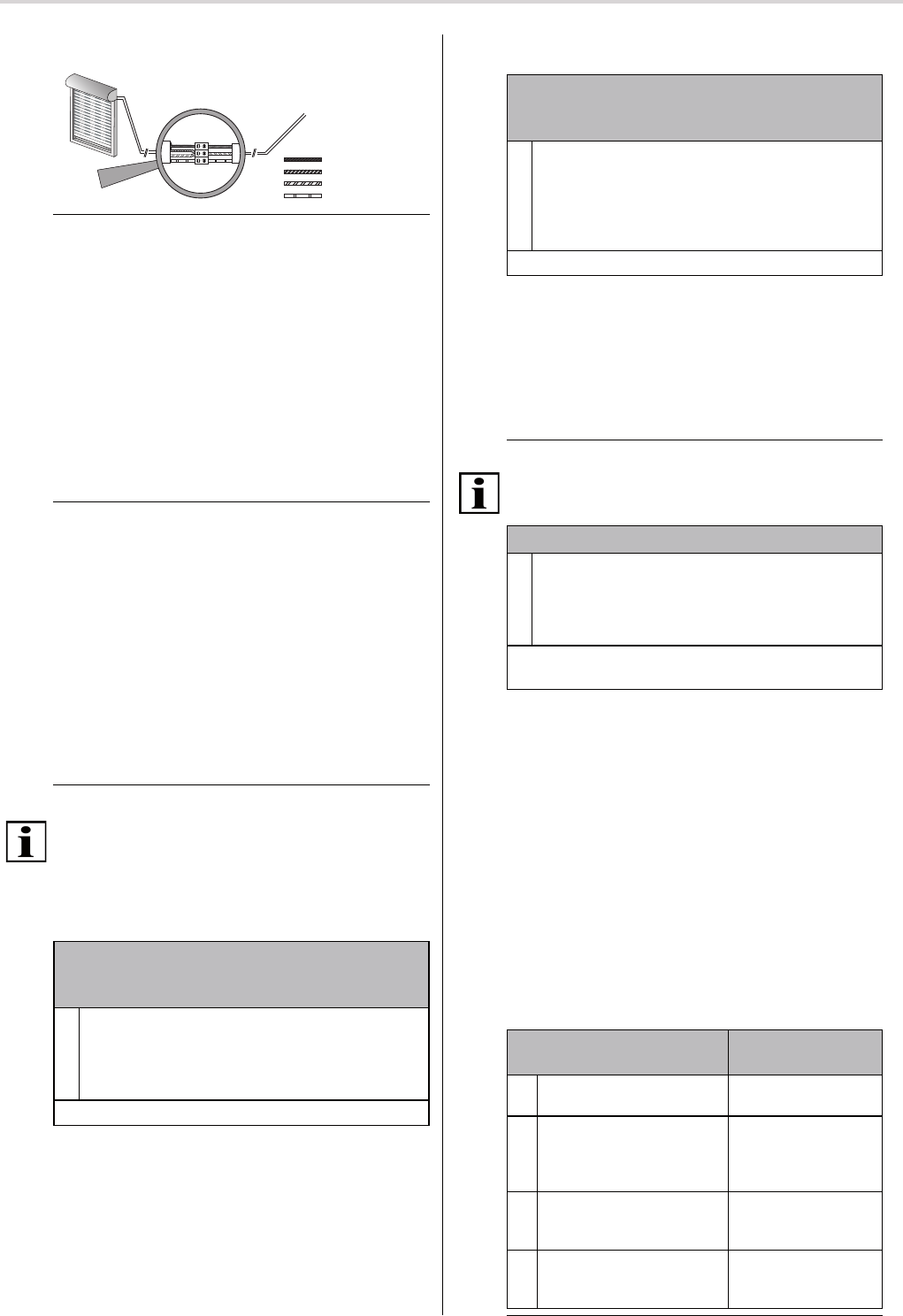
5.5.1 Installation cable connection
blue (neutral) (1)
black (2)
brown (3)
g
reen-yellow
Fig. 6 Installation cable connection
►Switch on power supply.
►Now, you can set the end positions with the elero instal-
lation cable.
1 Winding thermostat
2 Device plug
3 Junction box
(outside of roller shutter case)
4 Electronic
5 Condenser
sw black
br brown
bl blue
gr/ge green/yellow
6 | US+CA © elero GmbH
Installation: Electrical connection
5.2 Electrical connection
WARNING
Danger to life due to incorrect electrical connection.
Risk of electric shock.
►Before initial commissioning, check the correct connec-
tion of the PE conductor.
NOTE
Damage to the RolTop-915 due to incorrect electrical con-
nection.
►Before initial commissioning, check the correct connec-
tion of the PE conductor.
Damage to or destruction of the RolTop-915 due to ingress
of humidity.
►For devices with protection class IP44, the customer-
provided connection of cables or plugs (wiring) must also
be compliant with protection class IP44.
Damage to or destruction of the RolTop-915 for models
with 120 V 1 AC due to incorrect control.
►Switches that are preset to OFF (dead man) for drive
systems must be mounted in viewing range of the Rol-
Top-915 but away from moving parts and at a height
above 1.5 m.
Important
For electrical connection, generally no connection and dis-
connection of the connection cable or plug is necessary.
Particularly at the RolTop915 type S and depending on the
used mounting or adapter plate, it is necessary to remove
this screwed plate before replacing cables.
Only connect when the system is disconnected from
the voltage. To do so, disconnect the drive cable.
1 Use a suitable screwdriver to push the locking mecha-
nism of the device plug to the cable.
2 Disconnect the plug.
3 Insert the device plug until the locking mechanism enga-
ges.
Removing and inserting the device plug
Delivery con-
dition
Remove plug Insert plug
Fig. 4 Removing and inserting the device plug
→
1
→
2
→
3
5.5.2 Wireless connection (transmitter operation)
elero
Blue (neutral wire) (1)
Black (2)
Brown (3)
Green-yellow (4)
Fig. 7 Wireless connection (transmitter operation)
►Switch on power supply.
►The drive system moves up and down briefl y.
Now, the drive system is in wireless operation.
Now, you can program the transmitter(s).
5.6 End position and relief settings
Setting of end positions and relief can either be carried out
• by means of elero installation cable (ensure proper con-
nection according to section 5.5.1) or
• by means of a programmed transmitter.
Programming a transmitter for a drive system is descri-
bed in section 5.7.
Important preliminary consideration:
Before carrying out the end position settings, decide on
a certain relief function (different combinations available
according to the following models).
This will save you unnecessary time and effort during con-
fi guration!
Press one of the drive buttons until the drive system indica-
tes switchover to setting mode with a short automatic stop.
Now, you can set the end positions. After setting both end
positions, the setting mode is closed.
5.6.1 Relief function for end position(s)
If one end position was programmed to limit stop, an additi-
onal relief function can be activated for the fabric.
Important
The relief function is only active in wireless operation.
Activation of the relief function (for options B to D) is carried
out in one step with programming of the end positions (refer
to sections 5.6.7 to 5.6.9)!
5.6.2 Relief function at the upper stop
For option B (refer to section 5.6.7)
and option C (refer to section 5.6.8):
Activating the relief function at the upper limit stop
1 Using the installation cable or a programmed trans-
mitter, keep the UP button ▲ pressed from step
① (section 5.6.7 and 5.6.8) and press additionally
(simultaneously) the DOWNbutton ▼. Keep both
buttons pressed until the fabric stops.
The relief function at the upper limit stop is activated.
5.6.3 Relief function at the lower stop
For option C (refer to section 5.6.8)
and option D (refer to section 5.6.9):
Activating the relief function at the lower limit stop
1 In a medium fabric position, using the installation
cable or a programmed transmitter, keep the DOWN
button ▼ pressed from step ③ (section 5.6.8 and
5.6.9) and press additionally (simultaneously) the
UPbutton ▲. Keep both buttons pressed until the
fabric stops.
The relief function at the lower limit stop is activated.
5.6.4 Changing / deleting of end positions
and deleting the relief function
It is not possible to change or delete one individual end
position. This is always carried out in pairs (upper and lower
end position at once).
By deleting the end positions, also the setting of the optio-
nal relief function is lost.
Important
Complete, uninterrupted up and down movement is neces-
sary to adapt the fabric protection system to the fabric.
Changing / deleting of end positions
1 In a medium fabric position, using the installation
cable or a programmed transmitter, simultaneously
press both direction buttons (▲ and ▼) and keep
them pressed until the drive system briefl y moves up
and down.
Deleting the end position settings is completed.
The end positions can be reset.
5.6.5 Programming or deleting additional
fabric positions
Intermediate position programming:
refer to transmitter instructions.
Ventilation position programming:
refer to transmitter instructions.
Intermediate position deleting:
refer to transmitter instructions.
Ventilation position deleting:
refer to transmitter instructions.
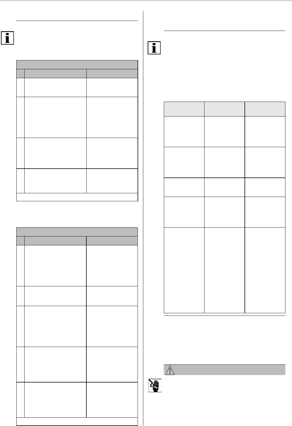
5.6.6 Four options for end position settings
Four different combinations of end position settings are
available that can be selected according to the technical
requirements of the fabric.
End position settings
(4 options)
possible with
A Upper and lower end positi-
on freely confi gurable
Suspension spring,
bands, belt
BFixed upper end position,
lower end position freely
confi gurable
Suspension spring,
bands, belt,
limit plug,
angle bracket
C Fixed upper
and lower end position
Anti-lift device, fi xed
shaft connector, limit
plug, angle bracket
DUpper end position freely
confi gurable, fi xed lower
end position
Anti-lift device
Fig. 8 Options of end position settings for RolTop-915
© elero GmbH US+CA | 7
Relief function | End position settings

5.6.9 Option C:
Fixed upper and lower end position
Option C: Fixed upper and lower end position
① In a medium fabric position, using the installation
cable or a programmed transmitter, press the UP
button ▲ until the fabric has reached the desired
upper end position (to upper limit stop).
The drive system starts, stops briefl y and starts
again (as long as the UP button ▲ is pressed).
The drive system automatically stops when reaching
the upper limit stop.
② Keep the DOWN button ▼ pressed until the drive
system stops automatically.
The upper end position is set.
Optional: Activation of the relief function for the
upper limit stop: refer to section 5.6.2.
③ Press the DOWN button ▼ again, until the fabric
has reached the lower end position (to bottom limit
stop).
The drive system starts, stops briefl y and starts
again (as long as the DOWN button ▼ is pressed).
The drive system automatically stops when reaching
the lower limit stop.
④ Keep the UP button ▲ pressed until the drive sys-
tem stops automatically.
The lower end position is set.
Optional: Activation of the relief function for the
lower limit stop: refer to section 5.6.3.
End position setting of option C is completed.
Fig. 11 End position setting option C:
5.6.10 Option D: Upper end position freely confi gu-
rable,
fi xed lower end position
Option D: Upper end position freely confi gurable,
fi xed lower end position
① In a medium fabric position, using the installation
cable or a programmed transmitter, press the UP
button ▲ until the fabric has reached the desired
upper end position.
The drive system starts, stops briefl y and starts
again (as long as the button is pressed).
Corrections can be made with the buttons ▲ and
▼.
② Keep the DOWN button ▼ pressed until the drive
system stops automatically.
The upper end position is set.
③ Press the DOWN button ▼ again, until the fabric
has reached the lower end position (to bottom limit
stop).
The drive system starts, stops briefl y and starts
again (as long as the DOWN button ▼ is pressed).
The drive system automatically stops when reaching
the lower limit stop.
④ Keep the UP button ▲ pressed until the drive sys-
tem stops automatically.
The lower end position is set.
Optional: Activation of the relief function for the
lower limit stop: refer to section 5.6.3.
End position setting of option D is completed.
Fig. 12 End position setting option D:
8 | US+CA © elero GmbH
End position settings
5.6.7 Option A: Upper and lower end position
freely confi gurable
Option A:
Upper and lower end position freely confi gurable
① In a medium fabric position, using the installation
cable or a programmed transmitter, press the UP
button ▲ until the fabric has reached the desired
upper end position.
The drive system starts, stops briefl y and starts
again (as long as the UP button ▲ is pressed).
Corrections can be made with the buttons ▲ and
▼.
② Keep the DOWN button ▼ pressed until the drive
system stops automatically.
The upper end position is set.
③ Press the DOWN button ▼ again, until the fabric
has reached the desired lower end position.
The drive system starts, stops briefl y and starts
again (as long as the DOWN button ▼ is pressed).
Corrections can be made with the buttons ▲ and
▼.
④ Keep the UP button ▲ pressed until the drive sys-
tem stops automatically.
The lower end position is set.
End position setting of option A is completed.
Fig. 9 End position setting option A:
5.6.8 Option B:
Fixed upper end position,
lower end position freely confi gurable
Option B: Fixed upper end position,
lower end position freely confi gurable
① In a medium fabric position, using the installation
cable or a programmed transmitter, press the UP
button ▲ until the fabric has reached the desired
upper end position (to upper limit stop).
The drive system starts, stops briefl y and starts
again (as long as the UP button ▲ is pressed).
The drive system automatically stops when reaching
the upper limit stop.
② Keep the DOWN button ▼ pressed until the drive
system stops automatically.
The upper end position is set.
Optional: Activation of the relief function for the
upper limit stop: refer to section 5.6.2.
③ Press the DOWN button ▼ again, until the fabric
has reached the desired lower end position.
The drive system starts, stops briefl y and starts
again (as long as the button is pressed).
Corrections can be made with the buttons ▲ and
▼.
④ Keep the UP button ▲ pressed until the drive sys-
tem stops automatically.
End position setting of option B is completed.
Fig. 10 End position setting option B:
5.7 Transmitter programming
Important
Requirement: The drive system must be in wireless opera-
tion.
►If the end positions are not programmed, the fabric is
loosened from the winding shaft.
Programming the (fi rst) transmitter
Instruction Result
1 Disconnecting and recon-
necting the power supply
For approx. 5 minutes,
the drive system is in
programming mode.
2 On the transmitter to be
programmed, press the
programming button P for
approx. 1 second.
The status indicator
fl ashes. Now (for
approx. 2 minutes),
the drive system is in
programming mode
(up and down move-
ment).
3 Immediately (max. 1 se-
cond) after start of the up
movement, press the UP
button ▲.
The status indicator
fl ashes briefl y. The
fabric stops briefl y,
moves on, stops and
moves downwards.
4Immediately (max. 1 se-
cond) after start of the
down movement, press the
DOWN button ▼.
The status indicator
fl ashes briefl y. The
drive system stops.
The (fi rst) transmitter is programmed.
5.8 Programming additional transmitters(s)
A maximum of 16 transmitters can be programmed.
Programming additional transmitters(s)
Instruction Result
1 For three seconds, on a
already programmed trans-
mitter press simultaneously
for 3 seconds
the UPbutton ▲,
the DOWNbutton ▼ and
the programming button P.
The status indicator
fl ashes. The drive sys-
tem is in programming
mode (up and down
movement).
(alternative to above line)
Disconnecting and recon-
necting the power supply
For approx. 5 minutes,
the drive system is in
programming mode.
2 On the (additional)
transmitter to be program-
med, press the program-
ming button P.
The status indicator
fl ashes briefl y. The
drive system is (for
approx. 2 minutes) in
programming mode
(up and down move-
ment).
4On the (additional)
transmitter to be program-
med, immediately (max. 1
second) after start of the up
movement, press the UP
button ▲.
The status indicator
fl ashes briefl y. The
fabric stops briefl y,
moves on, stops and
moves downwards.
5On the (additionally)
transmitter to be program-
med, immediately (max.
1 second) after start of a
down movement, press the
DOWNbutton ▼.
The status indicator
fl ashes briefl y. The
drive system stops.
Programming of the additional transmitter is complete.
Stopping the bidirectional wireless programming mode:
Press the STOP button for at least 6 seconds until the sta-
tus indicator is blinking (transmitter-dependent).
Important
Complete, uninterrupted up and down movement is neces-
sary to adapt the fabric protection system to the fabric.
5.9 Technical data
The separately available „technical data sheet“ will provide
you with an overview of the most important technical para-
meters.
6 Troubleshooting
Problem /
malfunction
Possible
cause
Remedy,
correction
• Drive system
stops during
movement
• End positions
not correctly
set
• Drive system is
in setting mode
• Set end posi-
tions
• Drive system
stops after a
short period of
time
• End positions
have been
saved
• Stiff fabric
• Set second
end position
• Check smooth
running of the
fabric
• Drive system
only runs in
one direction
• Connection
error
• Check connec-
tion
• Drive system
does not react
• No power
supply
• Temperature
limiter has
triggered
• Check power
supply
• Have the drive
system cool
down
• Program-
ming of end
positions not
possible
• Random drive
movements
• The distance
to the end
position or to
the limit stop is
too short
• Delete end
positions
Reset end
positions
• The drive sys-
tem must run,
stop briefl y
and start again
(as long as a
button on the
elero installa-
tion cable or a
programmed
transmitter is
pressed).
Fig. 13 RolTop-915 troubleshooting
7 Servicing
The RolTop-915 is maintenance-free.
8 Cleaning
WARNING
Risk of injury due to electricity.
Risk of electric shock.
►Risk due to potential live parts.
►Only carry out cleaning when the system is disconnected
from the voltage. To do so, disconnect the drive cable.
►Clean the product surface only with a soft, clean and dry
cloth.
© elero GmbH US+CA | 9
Transmitter programming | Troubleshooting
Declaration of Conformity | UL approval | Homologation UL
9 Repair
In case of questions, please contact your local specialist.
Please always provide the following information:
• Article number and designation on name plate
• Type of defect
• Previous and unusual occurrences
• Circumstances
• Own assumption
10 Address
elero GmbH
Antriebstechnik
Linsenhofer Str. 65
72660 Beuren
Germany
Phone: +49 7025 13-01
Fax: +49 7025 13-212
info@elero.de
www.elero.com
If you require a contact outside of Germany, please visit our
website.
11 Disposal / scrapping
After unpacking the system, dispose of the packaging mate-
rial according to applicable regulations.
After the last use, dispose of the product according to appli-
cable regulations.
Scrapping
When scrapping the product, applicable international, natio-
nal and local rules and regulations must be complied with.
Please observe the recycling and dismantling properties of
materials and components as well as environmental and
health risks during recycling and disposal.
Material groups like different plastics and metals must be
sorted and put into the recycling system or disposed of.
Disposal of electrotechnical and electrical components
Disposal and recycling of electrotechnical and electrical
components must be carried out according to the applicable
laws or national regulations.
12 EC Declaration of Conformity
EG-KONFORMITÄTSERKLÄRUNG
Wir erklären hiermit, dass das/die nachfolgend genannte/n Produkt/e der Maschinenrichtlinie 2006/42/EG
entspricht/entsprechen.
Produktbezeichnung:
Rohrmotor
• RolTop S-915 (120V/60Hz) alle Varianten
• RolTop M-915 (120V/60Hz) alle Varianten
Beschreibung: Einsteckantrieb für Rollläden mit 915 MHz Funkempfänger
Die Übereinstimmung der/s bezeichneten Produkte/s mit den wesentlichen Schutzanforderungen wird durch
Einhaltung folgender Richtlinien und Normen berücksichtigt:
• R&TTE-Richtlinie 1999/5/EG
• Niederspannungsrichtlinie 2006/95/EG
DIN EN 60335-2-97 (VDE 0700-97):2009
• DIN EN 14 202:2004
Beuren, 31.05.2012
Ralph Trost
-CE-Beauftragter-, -Doku-Bevollmächtigter-
Fig. 14 EC Declaration of Conformity RolTop-915
type S and M
13 US: Addendum to the manual
UL approval
This device complies with Part 15 of the FCC Rules and
with RSS-210 of Industry Canada. Operation is subject to
the following thwo conditions:
(1) this device may not cause harmful interference, and
(2) this device must accept any interference recieved, inclu-
ding interference that may cause undesired operation. Any
changes or modifi cations made to this device without the
express permission of the manufacturer may void the user‘s
authority to operate this device.
14 CA: Addendum au manuel
Homologation UL
Le présent appareil est conforme aux CNR-210 (et FCC
part 15) d‘Industrie Canada applicables aux appareils radio
exempts de licence. L‘exploitation est autorisée aux deux
conditions suivantes :
(1) l‘appareil ne doit pas produire de brouillage, et
(2) l‘utilisateur de l‘appareil doit accepter tout brouillage
radioélectrique subi, même si le brouillage est susceptible
d‘en compromettre le fonctionnement.
Technical modifications reserved
elero GmbH
Antriebstechnik Linsenhofer Straße 65
D-72660 Beuren info@elero.de
www.elero.com
Phone: +49 7025 13-01
Fax: +49 7025 13-212