Emerson 3411 Daniel 3410 Series Gas Ultrasonic Flow Meters Installation Manual User Bdd58288 719d 4571 83fd Bac3ebb816a2
User Manual: emerson 3411 Emerson Oxygen Equipment 3411 User Guide |
Open the PDF directly: View PDF ![]() .
.
Page Count: 144 [warning: Documents this large are best viewed by clicking the View PDF Link!]
- Daniel 3410 Series Gas Ultrasonic Flow Meters Installation Manual
- Contents
- Section 1: Introduction
- 1.1 Typical applications
- 1.2 Features and benefits
- 1.3 Acronyms, abbreviations and definitions
- 1.4 Daniel MeterLink software
- 1.5 Daniel 3410 Series meter design
- 1.6 Meter specifications
- 1.7 Pre-installation considerations
- 1.8 Safety
- 1.9 Daniel 3410 Series Certifications and Approvals
- 1.10 FCC compliance
- 1.11 References
- Section 2: Mechanical installation
- 2.1 Meter piping, lifting and mounting
- 2.2 Meter components
- 2.3 Piping recommendations
- 2.4 Meter safety for hoist rings and lifting slings
- 2.5 Mounting requirements in heated or cooled pipelines
- Section 3: Electrical installation
- 3.1 Cable length TTL mode
- 3.2 Cable length Open Collector mode
- 3.3 Grounding meter electronics housing
- 3.4 Conduit seals
- 3.5 Wiring and I/O
- 3.6 I/O connections
- 3.7 Security seal installation
- Section 4: Configuration
- Appendix A: Engineering drawings
- Appendix B: Open source licenses
- Appendix C: Index
Installation Manual
Part Number 3-9000-759Revision D
June 2014
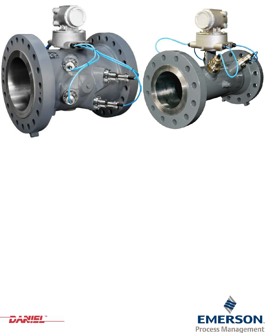
DanielTM 3410 Series Gas Ultrasonic Flow Meters
3414 Gas Ultrasonic Flow Meter 3411 and 3412 Gas Ultrasonic Flow Meters
Daniel customer service
E-mail
•Customer Service: tech.service@emersonprocess.com
•Customer Support: daniel.cst.support@emerson.com
•Asia-Pacific: danielap.support@emerson.com
•Europe: DanielEMA.CST@EmersonProcess.com
Location Telephone number Fax number
North America/Latin America +1.713.467.6000 +1.713.827.4805
Daniel Customer Service +1.713.827.6413 +1.713.827.6312
USA (toll free) +1.888.356.9001 +1.713.827.3380
Asia Pacific (Republic of Singapore) +65.6777.8211 +65.6777.0947.0743
Europe (Stirling Scotland, UK) +44 (0)1786.433400 +44 (0)1786.433401
Middle East Africa (Dubai, UAE) +971 4 8118100 +971 4 8865465
Return Material Authorization (RMA)
A Return Material Authorization (RMA) number must be obtained prior to returning any equipment for any reason.
Download the RMA form from the Support Services web page by selecting the link below.
www2.emersonprocess.com/EN-US/BRANDS/DANIEL/SUPPORT-SERVICES/Pages/Support-Services.aspx?
Signal words and symbols
Pay special attention to the following signal words, safety alert symbols and statements:
Important
Important is a statement the user needs to know and consider.
Tip
Tip provides information or suggestions for improved efficiency or best results.
Note
Note is a “general by-the-way” content not essential to the main flow of information.
This is a safety alert symbol. It is used to alert you to potential physical injury hazards. Obey
all safety messages that follow this symbol to avoid possible injury or death.
Safety alert symbol
Danger indicates a hazardous situation which, if not avoided, will result in death or serious
injury.
Warning indicates a hazardous situation which, if not avoided, could result in death or serious
injury.
Caution indicates a hazardous situation which, if not avoided, could result in minor or
moderate injury.
Caution indicates a hazardous situation which, if not avoided, could result in minor or
moderate injury.

Important safety instructions
Daniel Measurement and Control, Inc. (Daniel) designs, manufactures and tests products to
function within specific conditions. Because these products are sophisticated technical
instruments, it is important that the owner and operation personnel strictly adhere both to the
information printed on the product and to all instructions provided in this manual prior to
installation, operation, and maintenance.
Daniel also urges you to integrate this manual into your training and safety program.
BE SURE ALL PERSONNEL READ AND FOLLOW THE INSTRUCTIONS IN THIS MANUAL AND ALL
NOTICES AND PRODUCT WARNINGS.
Product owners (Purchasers):
•Use the correct product for the environment and pressures present. See technical data
or product specifications for limitations. If you are unsure, discuss your needs with your
Daniel representative.
•Inform and train all personnel in the proper installation, operation, and maintenance of
this product.
•To ensure safe and proper performance, only informed and trained personnel should
install, operate, repair and maintain this product.
•Verify that this is the correct instruction manual for your Daniel product. If this is not
the correct documentation, contact Daniel at 1-713-827-6314. You may also download
the correct manual from:
http://www.daniel.com
•Save this instruction manual for future reference.
•If you resell or transfer this product, it is your responsibility to forward this instruction
manual along with the product to the new owner or transferee.
•ALWAYS READ AND FOLLOW THE INSTALLATION, OPERATIONS, MAINTENANCE AND
TROUBLESHOOTING MANUALS AND ALL PRODUCT WARNINGS AND INSTRUCTIONS.
•Do not use this equipment for any purpose other than its intended service. This may
result in property damage and/or serious personal injury or death.
Installing, operating or maintaining a Daniel product improperly could lead to serious injury or
death from explosion or exposure to dangerous substances. To reduce this risk:
•Comply with all information on the product, in this manual, and in any local and national
codes that apply to the product.
•Do not allow untrained personnel to work with this product.
•Use Daniel parts and work procedures specified in this manual.
Product Operation Personnel:
•To prevent personal injury, personnel must follow all instructions of this manual prior to
and during operation of the product.
•Follow all warnings, cautions, and notices marked on, and supplied with, this product.
•Verify that this is the correct instruction manual for your Daniel product. If this is not
the correct documentation, contact Daniel at 1-713-827-6314. You may also download
the correct manual from:
http://www.daniel.com
•Read and understand all instructions and operating procedures for this product.
•If you do not understand an instruction, or do not feel comfortable following the
instructions, contact your Daniel representative for clarification or assistance.
•Install this product as specified in the INSTALLATION section of this manual per
applicable local and national codes.
•Follow all instructions during the installation, operation, and maintenance of this
product.
•Connect the product to the appropriate pressure and electrical sources when and
where applicable.
•Ensure that all connections to pressure and electrical sources are secure prior to and
during equipment operation.
•Use only replacement parts specified by Daniel. Unauthorized parts and procedures can
affect this product's performance, safety, and invalidate the warranty. “Look-a-like”
substitutions may result in deadly fire, explosion, release of toxic substances or
improper operation.
•Save this instruction manual for future reference.
Notice
THE CONTENTS OF THIS PUBLICATION ARE PRESENTED FOR INFORMATIONAL PURPOSES ONLY, AND WHILE
EVERY EFFORT HAS BEEN MADE TO ENSURE THEIR ACCURACY, THEY ARE NOT TO BE CONSTRUED AS
WARRANTIES OR GUARANTEES, EXPRESSED OR IMPLIED, REGARDING THE PRODUCTS OR SERVICES
DESCRIBED HEREIN OR THEIR USE OR APPLICABILITY. ALL SALES ARE GOVERNED BY DANIEL'S TERMS AND
CONDITIONS, WHICH ARE AVAILABLE UPON REQUEST. WE RESERVE THE RIGHT TO MODIFY OR IMPROVE THE
DESIGNS OR SPECIFICATIONS OF SUCH PRODUCTS AT ANY TIME.
DANIEL DOES NOT ASSUME RESPONSIBILITY FOR THE SELECTION, USE OR MAINTENANCE OF ANY PRODUCT.
RESPONSIBILITY FOR PROPER SELECTION, USE AND MAINTENANCE OF ANY DANIEL PRODUCT REMAINS
SOLELY WITH THE PURCHASER AND END-USER.
TO THE BEST OF DANIEL'S KNOWLEDGE THE INFORMATION HEREIN IS COMPLETE AND ACCURATE. DANIEL
MAKES NO WARRANTIES, EXPRESSED OR IMPLIED, INCLUDING THE IMPLIED WARRANTIES OF MERCHANTABIL-
ITY AND FITNESS FOR A PARTICULAR PURPOSE WITH RESPECT TO THIS MANUAL AND, IN NO EVENT, SHALL
DANIEL BE LIABLE FOR ANY INCIDENTAL, PUNITIVE, SPECIAL OR CONSEQUENTIAL DAMAGES INCLUDING, BUT
NOT LIMITED TO, LOSS OF PRODUCTION, LOSS OF PROFITS, LOSS OF REVENUE OR USE AND COSTS INCURRED
INCLUDING WITHOUT LIMITATION FOR CAPITAL, FUEL AND POWER, AND CLAIMS OF THIRD PARTIES.
PRODUCT NAMES USED HEREIN ARE FOR MANUFACTURER OR SUPPLIER IDENTIFICATION ONLY AND MAY BE
TRADEMARKS/REGISTERED TRADEMARKS OF THESE COMPANIES

Warranty and Limitations
1. LIMITED WARRANTY: Subject to the limitations contained in Section 2 herein, Daniel Measurement &
Control, Inc. (“Daniel”) warrants that the licensed firmware embodied in the Goods will execute the
programming instructions provided by Daniel, and that the Goods manufactured by Daniel will be free from
defects in materials or workmanship under normal use and care and Services will be performed by trained
personnel using proper equipment and instrumentation for the particular Service provided. The foregoing
warranties will apply until the expiration of the applicable warranty period. Goods are warranted for twelve (12)
months from the date of initial installation or eighteen (18) months from the date of shipment by Daniel,
whichever period expires first. Consumables and Services are warranted for a period of 90 days from the date
of shipment or completion of the Services. Products purchased by Daniel from a third party for resale to Buyer
("Resale Products”) shall carry only the warranty extended by the original manufacturer. Buyer agrees that
Daniel has no liability for Resale Products beyond making a reasonable commercial effort to arrange for
procurement and shipping of the Resale Products. If Buyer discovers any warranty defects and notifies Daniel
thereof in writing during the applicable warranty period, Daniel shall, at its option, correct any errors that are
found by Daniel in the firmware or Services or repair or replace F.O.B. point of manufacture that portion of the
Goods or firmware found by Daniel to be defective, or refund the purchase price of the defective portion of the
Goods/Services. All replacements or repairs necessitated by inadequate maintenance, normal wear and usage,
unsuitable power sources or environmental conditions, accident, misuse, improper installation, modification,
repair, use of unauthorized replacement parts, storage or handling, or any other cause not the fault of Daniel
are not covered by this limited warranty, and shall be at Buyer's expense. Daniel shall not be obligated to pay
any costs or charges incurred by Buyer or any other party except as may be agreed upon in writing in advance
by Daniel. All costs of dismantling, reinstallation and freight and the time and expenses of Daniel's personnel
and representatives for site travel and diagnosis under this warranty clause shall be borne by Buyer unless
accepted in writing by Daniel. Goods repaired and parts replaced by Daniel during the warranty period shall be
in warranty for the remainder of the original warranty period or ninety (90) days, whichever is longer. This
limited warranty is the only warranty made by Daniel and can be amended only in a writing signed by Daniel.
THE WARRANTIES AND REMEDIES SET FORTH ABOVE ARE EXCLUSIVE. THERE ARE NO REPRESENTATIONS OR
WARRANTIES OF ANY KIND, EXPRESS OR IMPLIED, AS TO MERCHANTABILITY, FITNESS FOR PARTICULAR
PURPOSE OR ANY OTHER MATTER WITH RESPECT TO ANY OF THE GOODS OR SERVICES. Buyer acknowledges
and agrees that corrosion or erosion of materials is not covered by this warranty.
2. LIMITATION OF REMEDY AND LIABILITY: DANIEL SHALL NOT BE LIABLE FOR DAMAGES CAUSED BY DELAY IN
PERFORMANCE. THE REMEDIES OF BUYER SET FORTH IN THIS AGREEMENT ARE EXCLUSIVE. IN NO EVENT,
REGARDLESS OF THE FORM OF THE CLAIM OR CAUSE OF ACTION (WHETHER BASED IN CONTRACT,
INFRINGEMENT, NEGLIGENCE, STRICT LIABILITY, OTHER TORT OR OTHERWISE), SHALL DANIEL'S LIABILITY TO
BUYER AND/OR ITS CUSTOMERS EXCEED THE PRICE TO BUYER OF THE SPECIFIC GOODS MANUFACTURED OR
SERVICES PROVIDED BY DANIEL GIVING RISE TO THE CLAIM OR CAUSE OF ACTION. BUYER AGREES THAT IN NO
EVENT SHALL DANIEL'S LIABILITY TO BUYER AND/OR ITS CUSTOMERS EXTEND TO INCLUDE INCIDENTAL,
CONSEQUENTIAL OR PUNITIVE DAMAGES. THE TERM “CONSEQUENTIAL DAMAGES” SHALL INCLUDE, BUT NOT
BE LIMITED TO, LOSS OF ANTICIPATED PROFITS, REVENUE OR USE AND COSTS INCURRED INCLUDING
WITHOUT LIMITATION FOR CAPITAL, FUEL AND POWER, AND CLAIMS OF BUYER'S CUSTOMERS.

Daniel Series 3410 Gas Ultrasonic Meter Installation Manual PrefaceTable of Contents
3-9000-759 Rev D June 2014
Section 1: Introduction i
Contents
Preface
Daniel customer service
Signal words and symbols
Important safety instructions
Notice
Warranty and Limitations
Section 1: Introduction
1.1 Typical applications ........................................................................................ 1
1.2 Features and benefits ...................................................................................... 2
1.3 Acronyms, abbreviations and definitions .......................................................... 3
1.4 Daniel MeterLink software ............................................................................... 6
1.5 Daniel 3410 Series meter design ...................................................................... 7
1.6 Meter specifications .................................................................................... 12
1.7 Pre-installation considerations....................................................................... 18
1.8 Safety .......................................................................................................... 18
1.9 Daniel 3410 Series Certifications and Approvals .............................................. 20
1.10 FCC compliance .......................................................................................... 21
1.11 References.................................................................................................. 22
Section 2: Mechanical installation
2.1 Meter piping, lifting and mounting ................................................................ 23
2.2 Meter components........................................................................................ 25
2.3 Piping recommendations .............................................................................. 29
2.4 Meter safety for hoist rings and lifting slings ................................................... 33
2.4.1 Use of appropriate safety engineered swivel hoist rings in meter end flanges..... 34
2.4.2 Appropriately rated lifting slings ........................................................................ 40
2.5 Mounting requirements in heated or cooled pipelines...................................... 42

ii Section 3: Electrical installation
PrefaceTable of Contents Daniel Series 3410 Gas Ultrasonic Meter Installation Manual
June 2014 3-9000-759 Rev D
Section 3: Electrical installation
3.1 Cable length TTL mode ..................................................................................43
3.2 Cable length Open Collector mode .................................................................43
3.3 Grounding meter electronics housing .............................................................44
3.4 Conduit seals ................................................................................................45
3.4.1 Startup for systems using explosion-proof conduit .............................................46
3.4.2 Startup for systems that use flame-proof cable ..................................................50
3.5 Wiring and I/O ..............................................................................................51
3.5.1 CPU Module labeling and LED indicators.............................................................52
3.6 I/O connections ............................................................................................57
3.6.1 Frequency/Digital outputs..................................................................................59
3.6.2 Analog input settings..........................................................................................62
3.6.3 Analog output settings .......................................................................................63
3.6.4 Digital Input........................................................................................................63
3.6.5 DHCP server switch settings ...............................................................................63
3.6.6 Configuration protect switch settings.................................................................64
3.6.7 External power source connection and fuse ........................................................65
3.7 Security seal installation................................................................................66
3.7.1 Seal Transmitter Electronics Enclosure................................................................66
3.7.2 Base Enclosure Security Seals..............................................................................68
3.7.3 Transducer assembly security seals.....................................................................70
3.7.4 Sealing the unit...................................................................................................71
Section 4: Configuration
4.1 Daniel MeterLink Setup..................................................................................73
4.2 Field Setup Wizard ........................................................................................74
4.3 Using AMS Device Manager to configure the meter ..........................................80
4.4 Using a Field Communicator to configure the meter ........................................95
4.5 Security seals for the meter (optional) ............................................................98

Daniel Series 3410 Gas Ultrasonic Meter Installation Manual PrefaceTable of Contents
3-9000-759 Rev D June 2014
Section 4: Configuration iii
Appendix A: Engineering drawings
A.1 3410 Series engineering drawings .................................................................................... 99
Appendix B: Open source licenses
B.1 GNU General Public License ............................................................................................ 102
B.2 GNU Lesser General Public License.................................................................................. 113
B.3 BSD Open Source License................................................................................................ 117
B.4 M.I.T License ................................................................................................................... 118
B.5 Zlib License ..................................................................................................................... 120
Appendix C: Index
C.1 Manual Index .................................................................................................................. 121

iv Section 4: Configuration
PrefaceTable of Contents Daniel Series 3410 Gas Ultrasonic Meter Installation Manual
June 2014 3-9000-759 Rev D

Daniel 3410 Series Ultrasonic Gas Flow Meter Installation Manual List of Tables
3-9000-759 Rev D June 2014
List of Tables v
List of Tables
Table 1-1 Daniel 3410 Series Gas Ultrasonic Meter acronyms, abbreviations and definitions ............ 3
Table 1-3 Performance specifications.............................................................................................. 13
Table 1-2 Meter specifications......................................................................................................... 13
Table 1-4 Transducer specifications................................................................................................. 15
Table 2-1 Hoist ring part number lookup table ................................................................................ 38
Table 2-2 Hoist Ring Lookup Table for Daniel 3414 Gas Meters........................................................ 39
Table 2-3 Hoist Ring Lookup Table for Daniel 3411 or 3412 Gas Meters........................................... 39
Table 3-1 Configurations for open collector frequency outputs....................................................... 43
Table 3-2 CPU Module labeling and LED functions ........................................................................... 53
Table 3-3 Ethernet cable to PC communication............................................................................... 54
Table 3-4 Serial Port A parameters................................................................................................... 56
Table 3-5 Frequency/Digital Outputs possible configurations.......................................................... 61
Table 3-6 DHCP server switch settings............................................................................................. 63
Table 3-7 Configuration protect switch settings .............................................................................. 64
Table 4-1 Local display labels, descriptions and valid units............................................................... 77
Table B-1 Open source licences .............................................................................................101

vi List of Tables
List of Tables Daniel 3410 Series Ultrasonic Gas Flow Meter Installation Manual
June 2014 3-9000-759 Rev D

Daniel 3410 Series Gas Ultrasonic Meter Installation Manual List of Figures
3-9000-759 Rev D June 2014
List of Figures vii
List of Figures
Figure 1-1 Daniel MeterLink download and registration ................................................................ 6
Figure 1-2 Daniel 3414 Gas Ultrasonic Flow Meter design ............................................................. 8
Figure 1-3 Daniel 3412 Gas Ultrasonic Flow Meter design ............................................................. 9
Figure 1-4 Daniel 3411 Gas Ultrasonic Flow Meter design .......................................................... 10
Figure 1-5 Transmitter electronics enclosure with local display and glass endcap ....................... 10
Figure 2-1 Daniel 3414 Flow Meter assembly............................................................................... 26
Figure 2-2 Daniel 3412 Flow Meter assembly .............................................................................. 27
Figure 2-3 Daniel 3411 Flow Meter assembly .............................................................................. 28
Figure 2-4 Transmitter electronics enclosure with optional local display and glass endcap .......... 28
Figure 2-5 Piping recommendations uni-directional without flow conditioner ............................ 30
Figure 2-6 Piping recommendations Uni-directional with flow conditioner ................................. 31
Figure 2-7 Piping recommendations Bi-directional flow with flow conditioner............................. 31
Figure 2-8 Meter end flange with tapped flat-counterbore hole for hoist ring ............................. 34
Figure 2-9 Safety approved hoist ring and non-compliant eye bolt ............................................. 35
Figure 2-10 90 Degree angle between slings ................................................................................. 36
Figure 2-11 Incorrect sling attachment.......................................................................................... 37
Figure 2-12 Correct sling attachment ........................................................................................... 40
Figure 2-13 Incorrect sling attachment.......................................................................................... 41
Figure 3-1 Internal Transmitter Electronics Enclosure chassis ground .......................................... 44
Figure 3-2 External ground lug .................................................................................................... 45
Figure 3-3 Electronics field wiring - upper terminal block, switches, ground lug ......................... 47
Figure 3-4 Transmitter electronics field wiring lower terminal block .......................................... 48
Figure 3-5 CPU Module labeling and LED indicators ..................................................................... 52
Figure 3-6 PC to meter serial connection wiring .......................................................................... 57
Figure 3-7 CPU Module I/O connections ...................................................................................... 58
Figure 3-8 CPU Module - Frequency/Digital outputs common ground ........................................ 62
Figure 3-9 CPU Module power source connections ..................................................................... 65
Figure 3-10 Transmitter electronics enclosure security latch ......................................................... 66
Figure 3-11 Transmitter Electronics Enclosure security seals ......................................................... 67

List of Figures Daniel 3410 Series Gas Ultrasonic Meter Installation Manual
June 2014 3-9000-759 Rev D
viii List of Figures
Figure 3-12 Base Enclosure wire seal installation 68
Figure 3-13 Base Enclosure security seals 69
Figure 3-14 Transducer assembly security seal70
Figure 4-1 AMS Device Description search81
Figure 4-2 AMS file download complete 82
Figure 4-3 AMS Device Manager 83
Figure 4-4 AMS Device Manager - Overview 83
Figure 4-5 AMS Device Manager - Guided Setup 84
Figure 4-6 AMS Device Manager - Service Tools All Variables status indicators86
Figure 4-7 Display Meter K-Factors86
Figure 4-8 AMS Device Manager - Configure Manual Setup87
Figure 4-9 Gating configuration parameter Edge gated, active high 89
Figure 4-10 Gating configuration parameter Edge gated, active low89
Figure 4-11 Gating configuration parameter State gated, active high89
Figure 4-12 Gating configuration parameter State gated, active low89
Figure 4-13 Configure Flow Analysis Alert 90
Figure 4-14 AMS Device Manager - Service Tools Alerts 91
Figure 4-15 Configuration changes dialog91
Figure 4-16 AMS Device Manager - Service Tools 92
Figure 4-17 AMS Device Manager - Service Tools All Variables 93
Figure 4-18 AMS Device Manager - Service Tools Trends 94
Figure 4-19 3414 transmitter field wiring conduit entries 96
Figure 4-20 Field Communicator wiring diagram for the 3410 Series electronics 97

Daniel 3410 Series Ultrasonic Gas Flow Meter Installation Manual Section 1: Introduction
3-9000-759 Rev D June 2014
Typical applications 1
11
Section 1: Introduction
Daniel 3410 Series Ultrasonic Gas Flow Meters have various configurations that meet a broad
range of customer requirements. Each meter comes fully assembled from DanielTM
Measurement and Control, Inc.
Refer to the following documents for additional details:
•P/N 3-9000-763 Daniel MeterLink Software for Gas and Liquid Ultrasonic Flow Meters
Quick Start Manual
•P/N 3-9000-761 HART® Field Device Specification Manual
•P/N 3-9000-769 Daniel 3410 Series Ultrasonic Gas Flow Meter Maintenance and
Troubleshooting Manual
Daniel 3414 Gas Ultrasonic Flow Meter technology provides custody transfer gas measurement
with the 3414 Model four-path (eight transducers) chordal design.
Model 3412 dual-path (four transducers) chordal design and Model 3411 single-path (two
transducers) chordal design provides check metering, pipeline balance, storage measurement,
production, or wet gas applications.
See Section 1.2 for advantages of Daniel 3410 Series Ultrasonic Gas Flow Meters.
1.1 Typical applications
Daniel 3410 Series Ultrasonic Gas Flow Meters have various configurations that meet a broad
range of customer requirements. Each meter comes fully assembled from Daniel. The
technology can be applied to custody transfer, allocation measurement, and check metering
applications such as:
•Custody transfer
•Power plants
•Large industrial users
•Production
•Underground storage sites
•Offshore
•Allocation measurement

2Features and benefits
Section 1: Introduction Daniel 3410 Series Ultrasonic Gas Flow Meter Installation Manual
June 2014 3-9000-759 Rev D
1.2 Features and benefits
•Proven long term stability
•Field proven reliability
•No line obstruction
•No pressure loss
•No moving parts
•Low maintenance
•Bi-directional measurement
•Extractable transducers
•Extensive self diagnostics
•Immediate alarm reporting
•Continuous Flow Analysis
—Abnormal profile
—Blockage
—Internal bore buildup
—Liquids present in the gas meter
—Reverse Flow
—Speed of Sound comparison error
•Auto-detected ASCII/RTU Modbus communications protocol
•Low power consumption
•Sophisticated noise reduction
•Internet-ready communications
•Ethernet access
•On-board LED status indicators
•Analog pressure and temperature inputs
•Communication via Emerson’s AMSTM Device Manager and Field Communicator
•API Chapter 21 compliant event and data logging (gas meters)
•Daniel MeterLink (a Windows®-based interface software)
•Local Display (optional)
For other features and benefits refer to the product datasheet:
http://www2.emersonprocess.com/EN-US/BRANDS/DANIEL/FLOW/Pages/Flow.aspx

Daniel 3410 Series Ultrasonic Gas Flow Meter Installation Manual Section 1: Introduction
3-9000-759 Rev D June 2014
Acronyms, abbreviations and definitions 3
1.3 Acronyms, abbreviations and definitions
Table 1-1 Daniel 3410 Series Gas Ultrasonic Meter acronyms, abbreviations and definitions
Acronym or abbreviation Definition
°degree (angle)
oCdegrees celsius (temperature unit)
oFdegrees fahrenheit (temperature unit)
ADC analog-to-digital converter
AI Analog Input
AMS® Device Manager Asset Management Software - Device Manager
AO Analog Output
ASCII MODBUS A Modbus protocol message framing format in which ASCII characters are used to
delineate the beginning and end of the frame. ASCII stands for American Standard
Code for Information Interchange.
boolean A type of data point that can only take on values of TRUE or FALSE (generally TRUE is
represented by a value of 1, FALSE is represented by a value of 0)
bps Bits Per Second (baud rate)
cPoise centipoise (viscosity unit)
CPU Central Processing Unit
CTS Clear-to-Send; the RS-232C handshaking signal input to a transmitter indicating that
it is okay to transmit data – i.e., the corresponding receiver is ready to receive data.
Generally, the Request-to-Send (RTS) output from a receiver is input to the Clear-to-
Send (CTS) input of a transmitter.
DAC Digital-to-Analog Converter
Daniel MeterLinkTM Daniel Ultrasonic Meter interface software
DI Digital Input
DO Digital Output
DHCP Dynamic Host Configuration Protocol
dm decimeter (10-1 meters, length unit)
ECC Error Correction Code
EEPROM Electrically-Erasable, Programmable Read-Only Memory
Flash non-volatile, programmable read-only memory
FODO output that is user configurable as either a Frequency or Digital Output
HART® Communication Protocol Highway Addressable Remote Transducer communications protocol
hr hour (time unit)
Hz Hertz (cycles per second, frequency unit)
I/O Input/Output

4Acronyms, abbreviations and definitions
Section 1: Introduction Daniel 3410 Series Ultrasonic Gas Flow Meter Installation Manual
June 2014 3-9000-759 Rev D
IS Intrinsically Safe
K Kelvin (temperature unit)
kHz kilohertz (103 cycles per second, frequency unit)
LAN Local Area Network
LED Light-emitting Diode
m meter (length unit)
m3/d cubic meters per day (volumetric flow rate)
m3/h cubic meters per hour (volumetric flow rate)
m3/s cubic meters per second (volumetric flow rate)
mA milliamp (current unit)
MAC Address Media Access Control (Ethernet Hardware Address -EHA)
microinch (μinch) microinch (10-6 in)
micron micrometer (10-6 m)
MMU Memory Management Unit
MPa megapascal (equivalent to 106 Pascal) (pressure unit)
N/A Not Applicable
Nm3/h normal cubic meters per hour
NOVRAM Non-Volatile Random Access Memory
Pa Pascal, equivalent to 1 newton per square meter (pressure unit)
Pa⋅s Pascal Second (viscosity unit)
PC Personal Computer
PFC Peripheral Field Connection (Board)
P/N Part Number
PS Power Supply (board)
psi pounds per square inch (pressure unit)
psia pounds per square inch absolute (pressure unit)
psig pounds per square inch gage (pressure unit)
RRadius of meter
rad radian (angle)
RAM Random Access Memory
RTS Request-to-Send; the RS-232C handshaking signal output by a receiver when it is
ready to receive data
RTU MODBUS A Modbus protocol framing format in which elapsed time between received charac-
ters is used to separate messages. RTU stands for Remote Terminal Unit.
Table 1-1 Daniel 3410 Series Gas Ultrasonic Meter acronyms, abbreviations and definitions
Acronym or abbreviation Definition
Daniel 3410 Series Ultrasonic Gas Flow Meter Installation Manual Section 1: Introduction
3-9000-759 Rev D June 2014
Acronyms, abbreviations and definitions 5
s second (time unit, metric)
SDRAM Synchronous Dynamic Random Access Memory
sec second (time unit, U.S. Customary)
TCP/IP Transmission Control Protocol/Internet Protocol
time_t seconds since Epoch (00:00:00 UTC Jan. 1, 1970) (time unit)
UDP User Datagram Protocol
U.L. Underwriters Laboratories, Inc. - product safety testing
and certification organization
V Volts (electric potential unit)
W Watts (power unit)
Table 1-1 Daniel 3410 Series Gas Ultrasonic Meter acronyms, abbreviations and definitions
Acronym or abbreviation Definition
6Daniel MeterLink software
Section 1: Introduction Daniel 3410 Series Ultrasonic Gas Flow Meter Installation Manual
June 2014 3-9000-759 Rev D
1.4 Daniel MeterLink software
Daniel MeterLinkTM software has robust features for setting communications parameters,
configuring your meter, collecting logs and reports and monitoring the meter health and alarm
statuses. Daniel MeterLink may be downloaded at no charge from:
http://www.daniel.com/um2.htm
Figure 1-1 Daniel MeterLink download and registration

Daniel 3410 Series Ultrasonic Gas Flow Meter Installation Manual Section 1: Introduction
3-9000-759 Rev D June 2014
Daniel 3410 Series meter design 7
Procedure
1. From the right panel under Quick Links, click the MeterLink Registration and Download
link.
2. Click the Order Now button to complete the Online registration form.
3. Click Next to go to the order confirmation page.
4. Click Complete Order.
You will receive a conformation e-mail with a hyperlink directing you to the download
site. Click the link provided.
5. Click Save.
Refer to the Daniel MeterLink Software for Gas and Liquid Ultrasonic Meters Quick Start Manual
(P/N 3-9000-763) for installation instructions and setup for initial communications. You may
download the manual from the Daniel MeterLink web page:
http://www2.emersonprocess.com/en-US/brands/daniel/Flow/ultrasonics/Pages/MeterLink.aspx
1.5 Daniel 3410 Series meter design
Daniel 3410 Series Gas Ultrasonic Flow Meters are designed to accurately measure products in
applications where reliable performance is critical, by measuring the difference in signal transit
time with and against the flow across one or more measurement path(s). A signal transmitted in
the flow direction travels faster than one transmitted against the flow direction. Each
measurement path is defined by a transducer pair in which each transducer alternately acts as
transmitter and receiver. The meter uses transit time measurements and transducer location
information to calculate the mean velocity.
8Daniel 3410 Series meter design
Section 1: Introduction Daniel 3410 Series Ultrasonic Gas Flow Meter Installation Manual
June 2014 3-9000-759 Rev D
Computer simulations of various velocity profiles demonstrate that multiple measurement
paths provide an optimum solution for measuring asymmetric flow.Daniel 3414 Gas Ultrasonic
Flow meters utilize four cross-bore, parallel-plane measurement paths that offer a high degree
of accuracy, repeatability, bi-directional measurement and superior low-flow capabilities
without the compromises associated with conventional technologies. These features make the
Daniel 3414 the best choice for custody transfer applications.
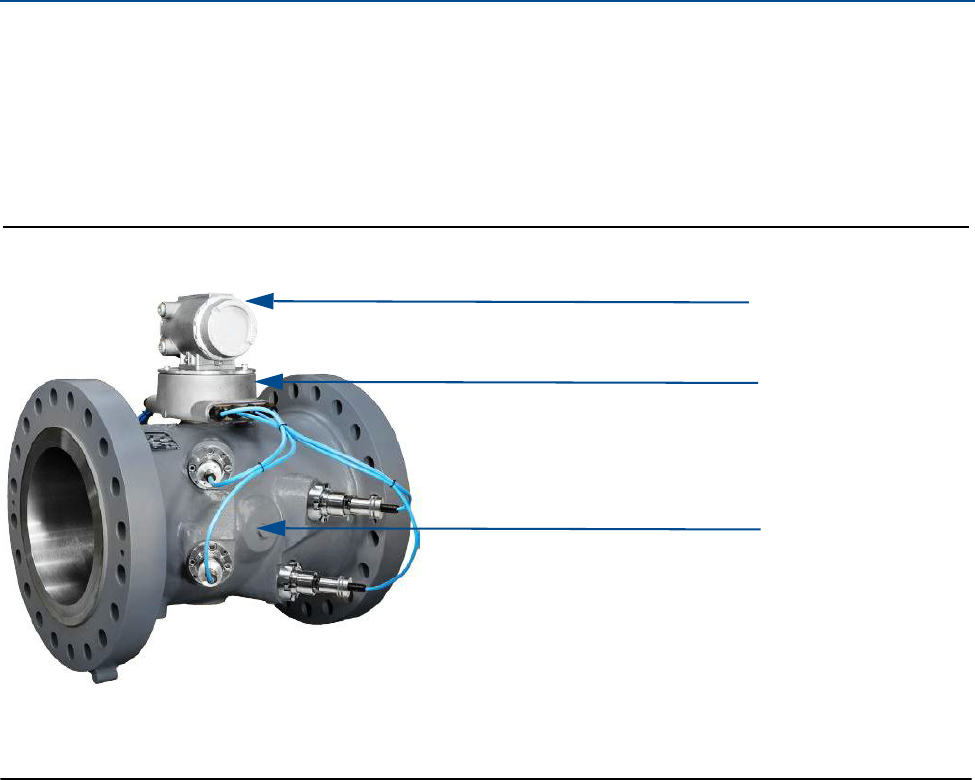
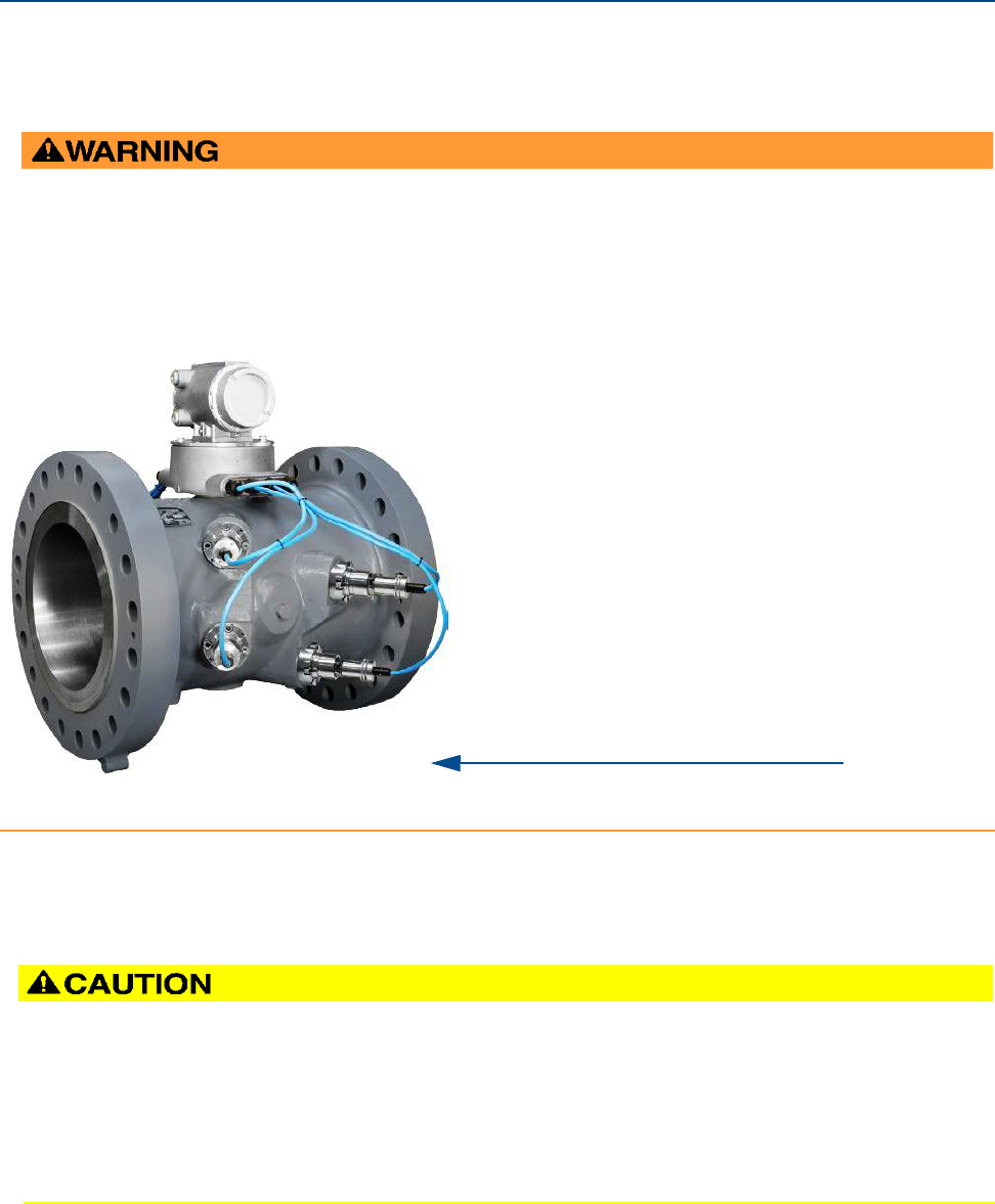
Figure 1-2 Daniel 3414 Gas Ultrasonic Flow Meter design
A. Transmitter electronics enclosure (explosion-proof) Optional - Local Display with glass endcap (Figure 1-4)
B. Base electronics enclosure (intrinsically safe)
C. Meter body with transducer assemblies (T-11, T-12, T-21 or T-22) (intrinsically safe)
A.
B.
C.
Daniel 3410 Series Ultrasonic Gas Flow Meter Installation Manual Section 1: Introduction
3-9000-759 Rev D June 2014
Daniel 3410 Series meter design 9
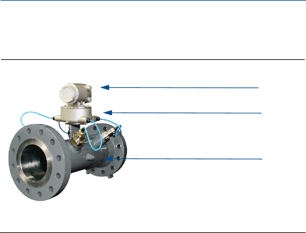
Daniel 3412 Gas Ultrasonic Flow meters utilize two-path in-line (four transducers) measurement
paths and are designed to measure the difference in signal transit time with and against the flow
across one or more measurement path(s). The two paths are configured at right angles to one
another in a “bulls-eye” arrangement.
Figure 1-3 Daniel 3412 Gas Ultrasonic Flow Meter design
A. Transmitter electronics enclosure (explosion-proof) Optional - Local Display with glass endcap (Figure 1-4)
B. Base electronics enclosure (intrinsically safe)
C. Meter body with transducer assemblies (T-11, T-12, T-21 or T-22) (intrinsically safe)
A.
B.
C.
10 Daniel 3410 Series meter design
Section 1: Introduction Daniel 3410 Series Ultrasonic Gas Flow Meter Installation Manual
June 2014 3-9000-759 Rev D
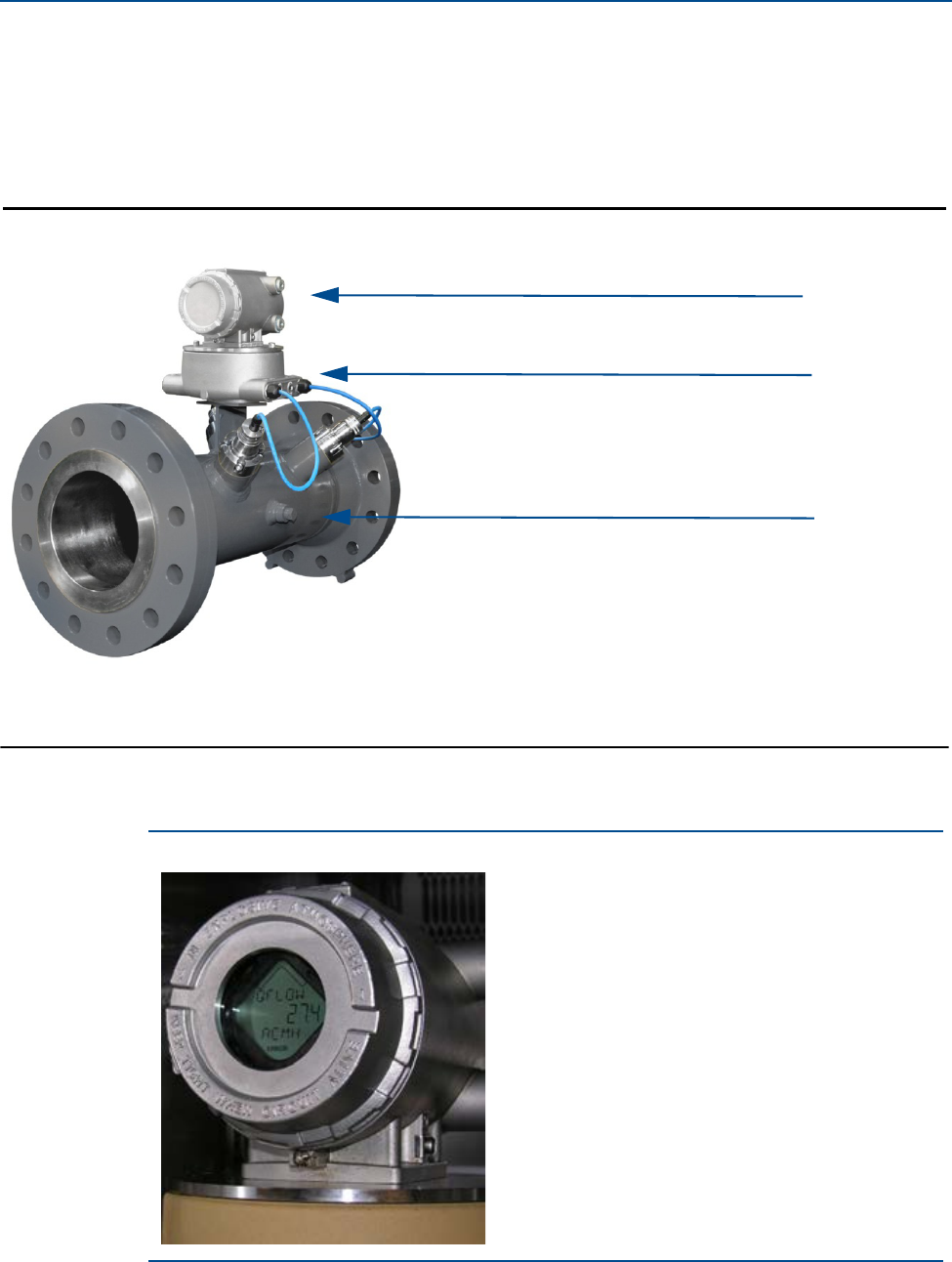
Daniel 3411 Gas Ultrasonic Flow meters are single-path (two transducer) Gas Ultrasonic Flow
Meter and is referred to as a bounce-path (as the signal is bounced off the meter body) or a
centerline path (as it goes through the centerline of the meter body) meter. The bounce-path
method simplifies construction of the meter and makes the meter less susceptible to
interference from pipeline liquids.
Figure 1-4 Daniel 3411 Gas Ultrasonic Flow Meter design
The Daniel Gas Ultrasonic Flow Meter design is available with an optional glass endcap and a
local display.
Figure 1-5 Transmitter electronics enclosure with local display and glass endcap
A. Transmitter electronics enclosure (explosion-proof) Optional - Local Display with glass endcap (Figure 1-4)
B. Base electronics enclosure (intrinsically safe)
C. Meter body with transducer assemblies (T-11, T-12, T-21 or T-22) (intrinsically safe)
A.
B.
C.

Daniel 3410 Series Ultrasonic Gas Flow Meter Installation Manual Section 1: Introduction
3-9000-759 Rev D June 2014
Daniel 3410 Series meter design 11
All Daniel ultrasonic flow meter’s U.L. safety listing is accomplished through the combination of
an explosion-proof transmitter electronics enclosure that houses the CPU module, Power
Supply board, I.S. Barrier board, Backplane board and optional LCD Display board.
Note: The optional LCD Display requires firmware v1.04 or later and Uboot version, January 31,
2013.
The Base Electronics Enclosure that houses the Acquisition Module. Intrinsically safe transducers
and cable assemblies are designed for Class 1, Division 1, Groups C and D areas without need of
further protection when installed in accordance with the field wiring diagram (refer to Daniel
drawing DMC - 005324 (see Appendix A).
12 Meter specifications
Section 1: Introduction Daniel 3410 Series Ultrasonic Gas Flow Meter Installation Manual
June 2014 3-9000-759 Rev D
1.6 Meter specifications
Consult your Daniel Sales and Service representative to ensure you purchase the correct
components and seals for your application.
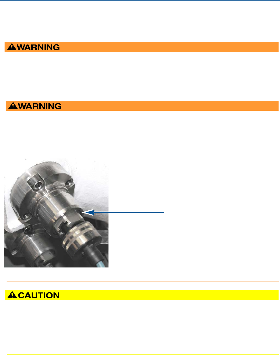
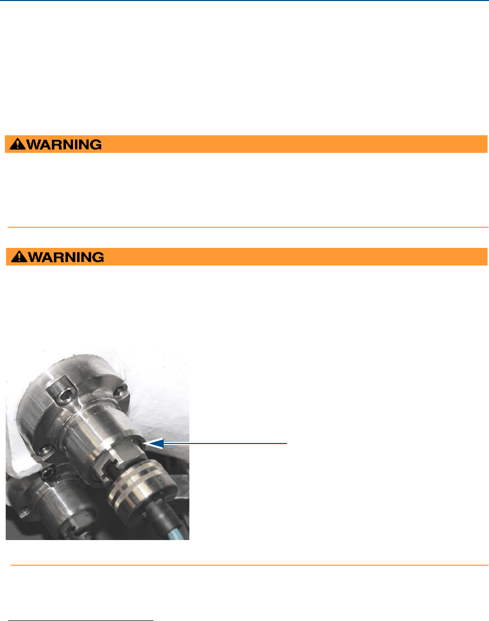
CONTENTS MAY BE UNDER PRESSURE
When the meter is under pressure, DO NOT attempt to remove or adjust the transducer holder.
Attempting to do so may release pressurized gases, resulting in serious injury or equipment damage
CONTENTS MAY BE HAZARDOUS
The meter must be fully depressurized and drained before attempting to remove the transducer holder.
If gas or fluid begins to leak from the transducer holder, stop immediately and reinstall the holder.
Failure to do so may cause serious injury or equipment damage.
A. Transducer holder
A.
ESCAPING GASES OR LIQUIDS HAZARD
The purchaser of the meter is responsible for the selection of Daniel components/seals and materials
compatible with the chemical properties of gas flow measurement.
Failure to select suitable meter components/seals may cause escaping gases or liquids, resulting in injury or
equipment damage.
Daniel 3410 Series Ultrasonic Gas Flow Meter Installation Manual Section 1: Introduction
3-9000-759 Rev D June 2014
Meter specifications 13
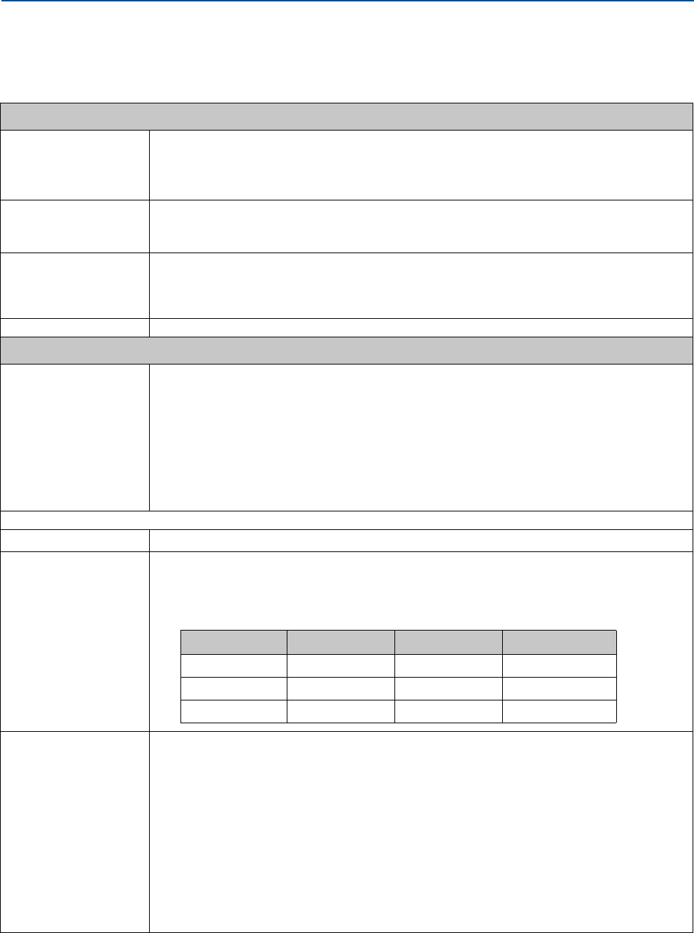
Specifications for Daniel 3410 Series Gas Ultrasonic Flow Meters are below:
Table 1-2 Meter specifications
Daniel 3411, 3412 and 3414 meter specifications
Meter type Number of paths
•3411 Daniel single path (two transducer) or center-line (bounce) design
•3412 Daniel two path (four transducer) center-line (bounce) design
•3414 Daniel four path (eight transducer) chordal design
Ultrasonic type
•Transit-time based measurement
•Spool piece with integral mount transducers
Enclosure materials • ASTM B26 Gr A356.0 T6 Aluminum
— 100% conversion coated and exterior coated with a polyurethane enamel
• ASTM A351 Gr CF8M Stainless Steel
—Passivated
Optional Local Display with a glass endcap on transmitter enclosure
Meter Performance
Linearity •Model 3414 Four-path meter chordal design
—± 0.3% of measured value over a 100:1 turndown 3-100 ft/s; 0.3 to 30 m/s) including lab
uncertainty
—Flow calibrated accuracy is ± 0.1% of reading relative to lab over entire flow calibration
range (Qmin - Qmax)
•Model(s) 3411 single-path or 3412 two-path
—Flow calibrated accuracy is ± 0.5% of reading relative to lab1
—Accuracy is typically ±1.5% of actual volume flow1(without flow calibration)
1. Does not take into consideration changes in wall roughness and installation effects.
Repeatability •±0.05% of reading in the specified velocity range from 5% to 100% (Qmax)
Velocity range •100 ft/s (30 m/s) with over-range)
•125 fps (38 m/s) on some line sizes
•Meter meets or exceeds AGA9 (2007) performance specifications
Body and Flange Sizes and
Pressure rating range
U.S. Customary Units - Meter sizes 4, 6, 8, 10, 12, 16, 18, 20, 24, 30, and 36 (inches)
•ANSI pressure classes 300, 600, 900 and 1500 (per ANSI B16.5)
•Carbon Steel
•316 Stainless Steel
Metric Units - Meter sizes DN - 100, 150, 200, 250, 300, 400, 450, 500, 600, 700, 750, 900
•PN 50, 100, 150, 200
•Carbon Steel
•316 Stainless Steel
Maximum Pressures
•Dependent on operating temperature
Meter bore
•Schedule 20, 30, 40, 60, 80, 100, 120, 140, 160, STD, XS, LW
Table 1-3 Performance specifications
Meter size 4” to 24” 30” 36”
Qmin(ft/s) 222
Qt (ft/s) 10 8.5 7.5
Qmax (ft/s) 100 85 75
14 Meter specifications
Section 1: Introduction Daniel 3410 Series Ultrasonic Gas Flow Meter Installation Manual
June 2014 3-9000-759 Rev D
Meter Performance
Flange types ANSI classes - 300, 600, 900 and 1500 (per ANSI B16.5)
Specific Gravity 0.35 to 1.50
Accuracy Limits Model 3414 accuracy limits (AGA 9 compliant) are:
•± 1% without a flow calibration (10” and smaller line sizes)
•± 0.7% without a flow calibration (for 12” and larger line sizes)
•±0.1% with a flow calibration
Model(s) 3411 and 3412 accuracy limits are:
•± 1.5% without a flow calibration
Minimum operating
pressure
100 psig (7 bar)
Electronic specifications
Power Meter
• 10.4 VDC to 36 VDC
• 11 W power consumption (15 W maximum)
\
Table 1-2 Meter specifications
Daniel 3410 Series Ultrasonic Gas Flow Meter Installation Manual Section 1: Introduction
3-9000-759 Rev D June 2014
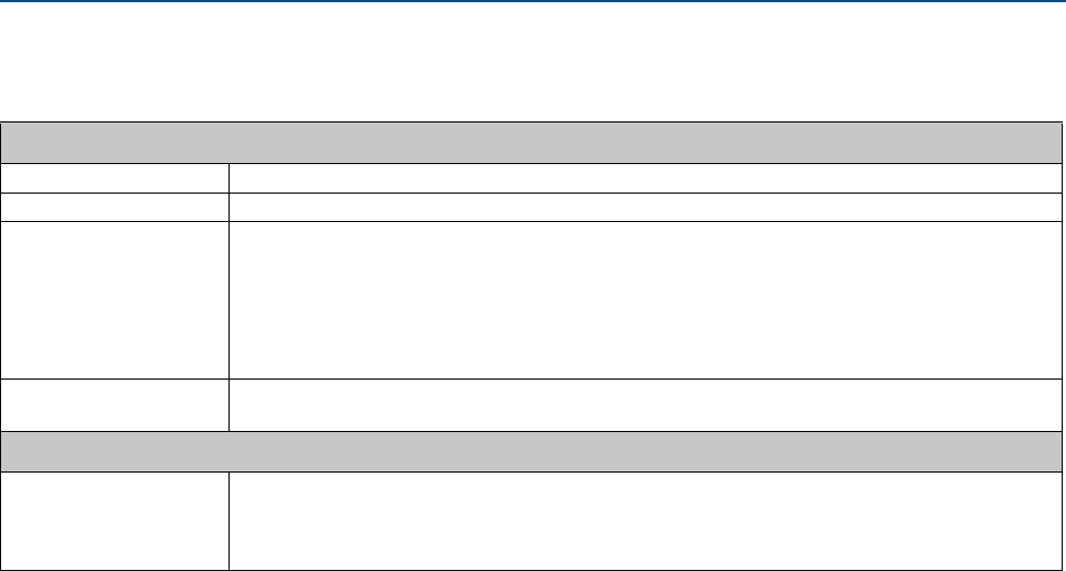
Meter specifications 15
Electronic specifications (Continued)
Transducer, mounts and holders
Note: The process temperature must not exceed the operating temperature range of the transducers.
Note: T-11 and T-21 transducers are designed for 12 inch and larger meters. T-12 and T-22 transducers are designed for 4"
through 10 meters.
Note: T-11 and T-21 transducers are used for all meter sizes for Models 3411 and 3412.
Note: The ultrasonic transducers are not intended for use across boundary walls of different hazardous area classifications. The
transmitter electronics cannot be remote mounted from Division 1 classification to a Division 2 area to meet an area
classification.
Table 1-2 Meter specifications
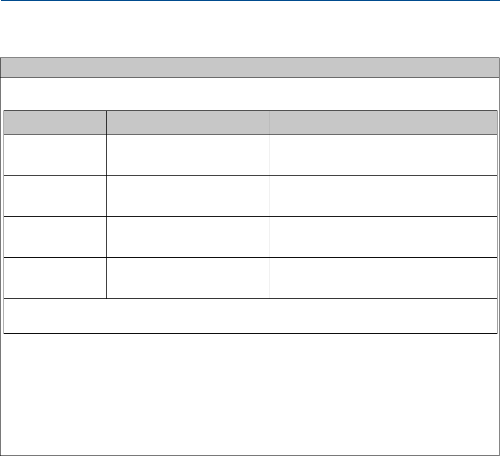
Table 1-4 Transducer specifications
Transducer type Temperature range Mount and holder type
T-11 -20 °C to +100 °C (-4 °F to 212 °F) Standard mounts/Holders, NBR O-ring
Inconel mounts/316L Holders, NBR O-ring
Inconel Mounts/Inconel Holders/FKM O-ring
T-12 -20 °C to +100 °C (-4 °F to 212 °F) Standard mounts/Holders, NBR O-ring
Inconel mounts/316L Holders, NBR O-ring
Inconel Mounts/Inconel Holders/FKM O-ring
T-211-20 °C to +100 °C (-4 °F to 212 °F) Standard mounts/Holders, NBR O-ring
Inconel mounts/316L Holders, NBR O-ring
Inconel Mounts/Inconel Holders/FKM O-ring
T-222-50 °C to +100 °C (-58°F to 212 °F) Standard mounts/Holders, NBR O-ring
Inconel mounts/316L Holders, NBR O-ring
Inconel Mounts/Inconel Holders/FKM O-ring
1. T-21 transducers use W-01 transformers
2. T-22 transducers use W-02 transformers
16 Meter specifications
Section 1: Introduction Daniel 3410 Series Ultrasonic Gas Flow Meter Installation Manual
June 2014 3-9000-759 Rev D
Communications specifications
Connectivity protocols One serial RS-232/RS-485 port (115 kbps baud rate) (Modbus RTU/ASCII)
•(1) Serial Port A
(RS-232/RS-485 Full Duplex/RS-485 Half Duplex)
One Ethernet Port (TCP/IP) 100 Base
•Up to 10 Mbps (internal connection) 100Mbps (external connection)
•Modbus TCP, TCP/IP
Device compatibility Daniel Ultrasonic flow meters are compatible with nearly every commercially available flow
computer. Examples: FloBoss 103, FloBoss S600 flow computer, ROC 107,
Digital, analog, and frequency inputs
Digital Input(s)
(Selectable)
(1) Single polarity
—Four pulse configurations available
Analog Input(s) (2) 4-20 mA
•AI-1 Temperature
•AI-2 Pressure
Note: The analog-to-digital conversion accuracy is within ±0.05% of full scale over the operating
temperature range.
Note: AI-1 and AI-2 are electronically isolated and operate in sink mode. The input contains a series
resistance so HART® Communicators can be connected to configure sensors.
A 24 Volt DC power output is available to provide power to the sensors.
Table 1-2 Meter specifications

Daniel 3410 Series Ultrasonic Gas Flow Meter Installation Manual Section 1: Introduction
3-9000-759 Rev D June 2014
Meter specifications 17
Digital, analog, and frequency outputs
Frequency/Digital
Output(s)
The meter has user-configurable selections for either a frequency output or digital status (FODO)
(Also see Section 3.6.1).
(3) Frequency/Digital Outputs
•FODO1 (four possible output configurations)
•FODO2(eight possible output configurations)
•FODO3(eight possible output configurations)
Frequency or Digital Output parameter pairs (see Section 3.6.1)
Frequency or Digital Outputs (FODO 1) source selections:
•(FO1A, DO1A, FO1B, DO1B)
Frequency or Digital Outputs (FODO 2) source selections
•(FO1A, DO1A, FO1B, DO1B, FO2A, DO2A, FO2B, DO2B)
Frequency or Digital Outputs (FODO 3) source selections
•(FO1A, DO1A, FO1B, DO1B, FO2A, DO2A, FO2B, DO2B)
Mode options:
•Open Collector (requires external excitation supply voltage and pull-up resistor)
•TTL (internally powered by the meter 0-5 VDC signal)
Channel B Phase options:
•Lag forward, Lead reverse (Phase B lags Phase A while reporting forward flow, leads Phase A
while reporting reverse flow)
•Lead forward, Lag reverse (Phase B leads Phase A while reporting forward flow, lags Phase A
while reporting reverse flow)
Phase A and Phase B output (based on flow direction)
•Reverse flow - output only reports flow in the reverse direction. For frequency outputs, Phase B
of the output is 90 degrees out of phase with Phase A.
•Forward flow - output only reports flow in the forward direction. For frequency outputs, Phase
B of the output is 90 degrees out of phase with Phase A.
•Absolute - output reports flow in both directions. For frequency outputs, Phase B of the output
is 90 degrees out of phase with Phase A.
• Bidirectional - output reports flow on Phase A only in the forward direction and on Phase B
only in the reverse direction.
Maximum frequency for the frequency outputs
•1000Hz
•5000Hz
Analog Output(s) •(1) 4-20 mA independently configurable analog output (HART)
(1) 4-20 mA independently configurable analog output (conventional)
The analog output zero scale offset error is within ±0.1% of full scale and gain error is within
±0.2% of full scale. The total output drift is within ±50 ppm of full scale per °C.
Table 1-2 Meter specifications

18 Pre-installation considerations
Section 1: Introduction Daniel 3410 Series Ultrasonic Gas Flow Meter Installation Manual
June 2014 3-9000-759 Rev D
1.7 Pre-installation considerations
•Pipeline equipment code compliance, ANSI, ASME, etc.
•Proper Inlet/outlet meter tube piping for reasonable stable flow to the settling chamber
(first meter tube spool upstream of the meter).
•Electrical safety compliance; UL, CSA, ATEX, IECEx etc.
•Civil and structural good practices compliance
•Contractual agreements or governmental compliance (or both)
•In-situ performance test procedures
•Field tested meter health check and flow dynamics diagnostics
•Data collection and retention procedures
1.8 Safety
The Daniel 3410 Series Gas Ultrasonic Flow Meter is suitable for use in U.L. Class 1, Division 1,
Group C and D hazardous locations.
Refer to the 3410 Series Systems Wiring Diagram, Sheet 3 (P/N DMC -005324) for the
certification tag (see Appendix A).
An “X” signifies the user should contact Daniel Measurement and Control, Inc. for
information on the dimensions of the flameproof joints.
Daniel 3410 Series Ultrasonic Gas Flow Meter Installation Manual Section 1: Introduction
3-9000-759 Rev D June 2014
Safety 19
Daniel 3410 Series Liquid Ultrasonic Meters are INMETRO certified. Refer to the 3410 Series
Liquid Ultrasonic Flow Meter Tag, INMETRO Certification drawing DMC - 006224.
Certificate number: NCC 11.0163 X
Marking: --Ex d ia IIB T4 Gb IP66 W
Electrical parameters: Refer to Section 1.6, Table 1-1
Special conditions for safe use
• Explosion proof joint dimensions are compliant with the Brazilian Association of
technical standard: ABNT NBR IEC 60079-1, Table 3.
• The enclosure for the explosion proof transmitter and intrinsically safe barrier must be
remote mounted (refer to Section 1.6, Table 1-2) if the operating temperature exceeds 1
40 oF (60 oC) (refer to Section 1.6, Table 1-2)
• Cable length (refer to Section 1.6, Table 1-2)
EXPLOSION OR FIRE HAZARD
Conduit runs must have a sealing fitting within 18 inches (457 mm) of the enclosure to reduce the risk of
an explosion or a fire.
•During operation, keep covers tight.
•During equipment maintenance, disconnect power before opening transmitter or base
electronics. Clean cover joints before replacing.
•DO NOT substitute meter components. Component substituting may compromise the intrinsic
safety.
Failure to do so may result in severe injury to personnel or cause damage to the equipment.

20 Daniel 3410 Series Certifications and Approvals
Section 1: Introduction Daniel 3410 Series Ultrasonic Gas Flow Meter Installation Manual
June 2014 3-9000-759 Rev D
1.9 Daniel 3410 Series Certifications and Approvals
Daniel 3410 Series Gas Ultrasonic Flow Meters have electrical, metrology, intrinsic safety and
Pressure Equipment Directive certifications and approvals by the agencies listed below. Refer to
the nameplate tag on the meter body, the wiring diagram (P/N DMC - 005324) in Appendix A
and observe all safety precautions. Daniel 3410 Series Gas Ultrasonic Flow Meters operate
within the pressure and temperature range of the device (also see Section 1.6 for meter specifi-
cations). Daniel 3410 Series Gas Ultrasonic Flow Meters are approved to the
ATEX Directive 94/9/EC.
Standards
•US
• Canada
•Europe
- Explosive Atmospheres (ATEX)
- International Electrotechnical Commission (IECEx)
- Pressure Equipment Directive (PED via BSI)
- Electromagnetic Compatibility (EMC)
- International Organization of Legal Metrology (OIML)
Approval Agencies
•UL
•ULC
•DEMKO
•INMETRO
•NEPSI
•GOSTR
IMPORTANT
Please consult Daniel Customer Service for the complete metrology approvals list.

Daniel 3410 Series Ultrasonic Gas Flow Meter Installation Manual Section 1: Introduction
3-9000-759 Rev D June 2014
FCC compliance 21
1.10 FCC compliance
This equipment has been tested and found to comply with the limits for a Class A digital device,
pursuant to Part 15 of the FCC Rules. These limits are designed to provide reasonable protection
against harmful interference when the equipment is operated in a commercial environment.
This equipment generates, uses, and can radiate radio frequency energy and, if not installed and
used in accordance with the instruction manual, may cause harmful interference to radio
communications. Operation of this equipment in a residential area is likely to cause harmful
interference in which case the user will be required to correct the interference at his own
expense.
Changes or modifications not expressly approved by the party responsible for compliance
could void the user's authority to operate the equipment.

22 References
Section 1: Introduction Daniel 3410 Series Ultrasonic Gas Flow Meter Installation Manual
June 2014 3-9000-759 Rev D
1.11 References
[1] Gould Modbus Protocol Reference Guide, Rev. B, PI-MBUS-300
[2] Measurement of Fuel Gas By Turbine Meters, American Gas Association, Transmission
Measurement Committee Report No. 7, Second Revision, April 1996 (also referred to as
AGA7)
[3] Compressibility Factors of Natural Gas and Other Related Hydrocarbon Gases, American
Gas Association, Transmission Measurement Committee Report No. 8, Second Edition,
Second Printing, July 1994 (also referred to as AGA8)
[4] Speed of Sound in Natural Gas and Other Related Hydrocarbon Gasses, Report 10, First
Edition, May 2003 (also referred to as AGA10)
[5] Manual of Petroleum Measurement Standards, Chapter 21 — Flow Measurement Using
Electronic Metering Systems, Section 1 — Electronic Gas Measurement, American Gas
Association and American Petroleum Institute, First Edition, September 1993
[6] AGA Report No. 9, Measurement of Gas by Multipath Ultrasonic Meters, Second Edition
(April 2007)
Daniel 3410 Series Ultrasonic Gas Flow Meter Installation Manual Section 2: Mechanical installation
3-9000-759 Rev D June 2014
Meter piping, lifting and mounting 23
Section 2: Mechanical installation
2.1 Meter piping, lifting and mounting
Refer to the following sections for piping recommendations, lifting with hoist rings and slings,
mounting in heated or cooled pipelines and safety warnings and precautions.
SURFACE TEMPERATURE HAZARD
The meter body and piping may be extremely hot or cold.
Wear appropriate personal protective equipment when coming in contact with the meter. Failure to do so may
result in injury.
CUTTING HAZARD
Sharp edges may be present on the meter.
Wear appropriate personal protective equipment when working on the meter. Failure to do so may cause
serious injury.
TRANSPORTATION HAZARD
When moving the meter, do not insert the forks of a forklift into the bore.
inserting the forks may cause the meter to become unstable, resulting in injury or damage to the bore and
sealing face.
TRIPPING HAZARD
Clear all obstacles or obstructions from the work area when transporting, installing or removing the
meter.
Failure to clear the work area may cause injury to personnel.
24 Meter piping, lifting and mounting
Section 2: Mechanical installation Daniel 3410 Series Ultrasonic Gas Flow Meter Installation Manual
June 2014 3-9000-759 Rev D
Consult your Daniel Sales and Service representative to ensure you purchase the correct
components and seals for your application.
CRUSHING HAZARD
Do not remove flange stabilizers.
Attempting to do so may allow the meter to roll, resulting in serious injury or equipment damage.
A.
A. Flange stabilizers
ESCAPING GASES OR LIQUIDS HAZARD
The purchaser of the meter is responsible for the selection of Daniel components/seals and materials
compatible with the chemical properties of gas flow measurement.
Failure to select suitable meter components/seals may cause escaping gases or liquids, resulting in injury or
equipment damage.
Daniel 3410 Series Ultrasonic Gas Flow Meter Installation Manual Section 2: Mechanical installation
3-9000-759 Rev D June 2014
Meter components 25
2.2 Meter components
Daniel 3410 Series Gas Ultrasonic Flow Meters are assembled, configured and tested at the
factory. The meter components include the transmitter electronics enclosure, the base
electronics enclosure and the meter body with transducer assemblies. 1
1. Refer to the 3-9000-744 Split Clamp Extractor Tool Operation Manual to remove the transducer holders while the
meter is pressurized.
CONTENTS MAY BE UNDER PRESSURE
When the meter is under pressure, DO NOT attempt to remove or adjust the transducer holder.
Attempting to do so may release pressurized gases, resulting in serious injury or equipment damage
CONTENTS MAY BE HAZARDOUS
The meter must be fully depressurized and drained before attempting to remove the transducer holder.
If gas or fluid begins to leak from the transducer holder, stop immediately and reinstall the holder.
Failure to do so may cause serious injury or equipment damage.
A. Transducer holder
A.
26 Meter components
Section 2: Mechanical installation Daniel 3410 Series Ultrasonic Gas Flow Meter Installation Manual
June 2014 3-9000-759 Rev D
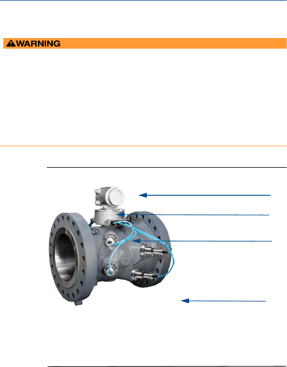
The 3414 four path ultrasonic meter components are shown below.
Figure 2-1 Daniel 3414 Flow Meter assembly
EXPLOSION OR FIRE HAZARD
Conduit runs must have a sealing fitting within 18 inches (457 mm) of the enclosure to reduce the risk of
an explosion or a fire.
• During operation, keep covers tight.
• During equipment maintenance, disconnect power before opening transmitter or base
electronics. Clean cover joints before replacing.
• DO NOT substitute meter components. Component substituting may compromise the intrinsic
safety.
Failure to do so may result in severe injury to personnel or cause damage to the equipment.
A. Explosion-proof transmitter enclosure (CPU Module, Power Supply, I.S. Barrier Board
B. Intrinsically-safe base enclosure includes Acquisition Module
C. Meter - body and transducer assemblies and cables
A.
B.
C.
D.
D. Flange stabilizers
Backplane board, (Optional: glass endcap for Local Display)
Daniel 3410 Series Ultrasonic Gas Flow Meter Installation Manual Section 2: Mechanical installation
3-9000-759 Rev D June 2014
Meter components 27
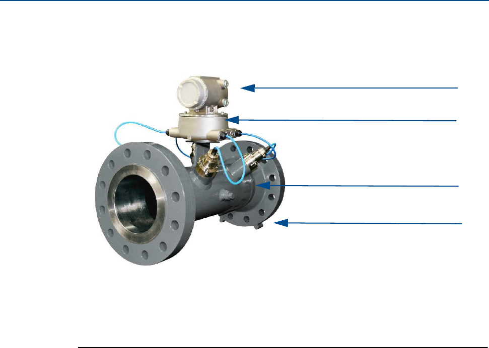
The 3412 dual path ultrasonic meter components are shown below.
Figure 2-2 Daniel 3412 Flow Meter assembly
A.
B.
C.
A. Explosion-proof transmitter enclosure (CPU Module, Power Supply, I.S. Barrier Board
B. Intrinsically-safe base enclosure includes Acquisition Module
C. Meter - body and transducer assemblies and cables
D. Flange stabilizers
Backplane board. (Optional: glass endcap for Local Display)
D.
28 Meter components
Section 2: Mechanical installation Daniel 3410 Series Ultrasonic Gas Flow Meter Installation Manual
June 2014 3-9000-759 Rev D
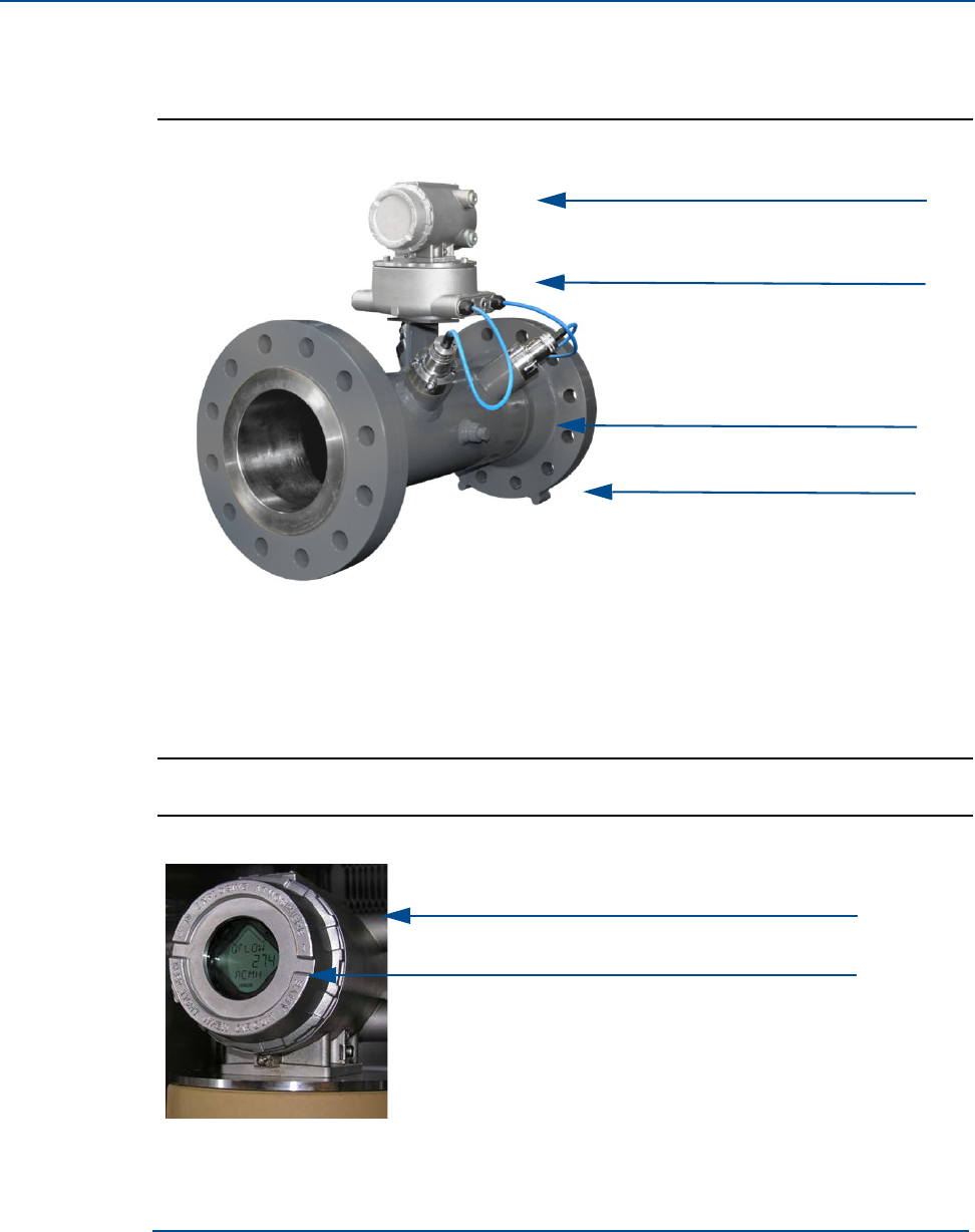
The 3411 single path ultrasonic meter components are shown below.
Figure 2-3 Daniel 3411 Flow Meter assembly
Figure 2-4 Transmitter electronics enclosure with optional local display and glass endcap
A.
B.
C.
A. Explosion-proof transmitter enclosure (CPU Module, Power Supply, I.S. Barrier Board
B. Intrinsically-safe base enclosure includes Acquisition Module
C. Meter - body and transducer assemblies and cables
D. Flange stabilizers
Backplane board. (Optional: glass endcap for Local Display)
D.
A.
B.
A. Transmitter electronics enclosure with glass endcap
B. Local display
Daniel 3410 Series Ultrasonic Gas Flow Meter Installation Manual Section 2: Mechanical installation
3-9000-759 Rev D June 2014
Piping recommendations 29
2.3 Piping recommendations
Sunshields, provided by the customer, may be required to prevent exceeding the process fluid
temperature when the meter is mounted in a location with extremely hot climates.
BURST HAZARD
Before pipeline cleaning and maintenance ("pigging operations"), remove straightening vanes or flow
conditioners. Failure to do so may cause excessive pressure in the meter system, resulting in serious injury/
death or equipment damage.
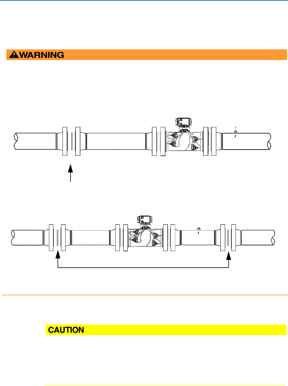
3410 Series Gas Ultrasonic Flow Meter with flow conditioner for uni-directional flow
3410 Series Gas Ultrasonic Flow Meter with flow conditioner for bi-directional flow
Flow conditioner: Daniel Profiler or CPA 50E
Straightening device
Straightening device
Flow conditioner: Daniel Profiler or CPA 50E
SUNSHIELD PROTECTION
Install a sunshield to prevent prolonged exposure to direct sunlight in extreme climates.
Failure to shield the meter may result in exceeding the process temperature range and damage
transmitter electronics.
30 Piping recommendations
Section 2: Mechanical installation Daniel 3410 Series Ultrasonic Gas Flow Meter Installation Manual
June 2014 3-9000-759 Rev D
Flow conditioning is recommended for best measurement results
•Honed or un-honed meter tube(s)
•Flow direction (unidirectional or bidirectional)
•Correct meter size selection - too low may cause poor flow stability (thermal
convection or too fast may cause erosion problems and resonance, cracks or failure of
probes or thermowells (approximately 0.3 to 30 m/sec or 1 to 100 ft/sec).
•Space availability for meter lengths (to allow inlet piping customization)
•Concentric alignment pins or flange concentricity technique considerations
IMPORTANT
The bore of the mating piping should be within 1% of the meter inside diameter.
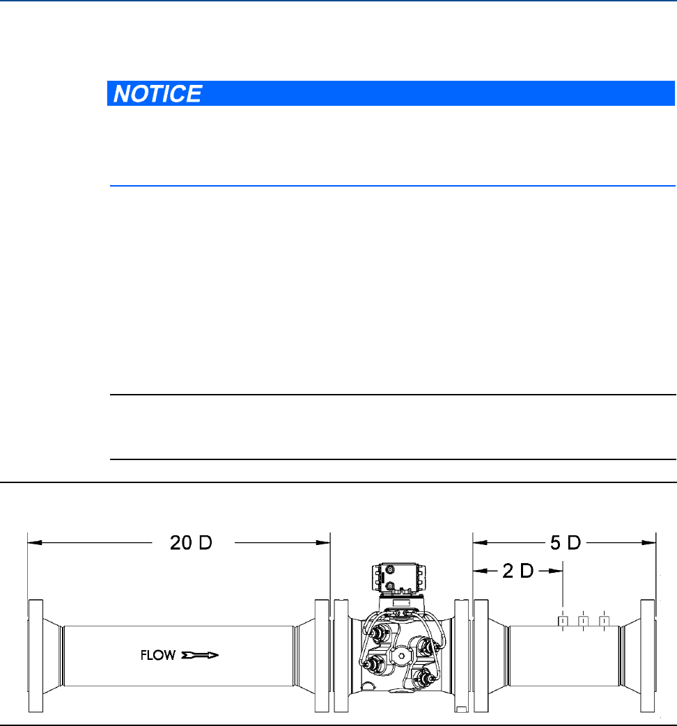
Figure 2-5 Piping recommendations uni-directional without flow conditioner
For optimal flow measurement conditions, Daniel suggests the piping configurations below.
Regardless of the configuration selected, the user agrees to accept full responsibility for the
site piping design and installation.
Daniel 3410 Series Ultrasonic Gas Flow Meter Installation Manual Section 2: Mechanical installation
3-9000-759 Rev D June 2014
Piping recommendations 31
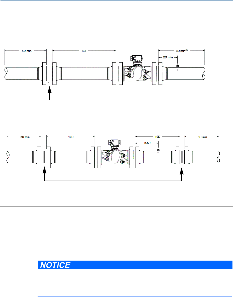
Figure 2-6 Piping recommendations Uni-directional with flow conditioner
Figure 2-7 Piping recommendations Bi-directional flow with flow conditioner
All pipe lengths are minimum:
•D = Nominal pipe size in inches (i.e. 6” pipe size; 10 D = 60 in)
•P = Pressure measurement location
•T = Temperature measurement location
http://www2.emersonprocess.com/en-US/brands/daniel/Flow/ultrasonics/Pages/Ultrasonic-
Series-3400.aspx
•The meter is provided with dowel pins to align the meter body bore with the bore of the
mating piping.
Flow conditioner: Daniel Profiler or CPA 50E
Straightening device
Straightening device
Flow conditioner: Daniel Profiler or CPA 50E
To access the product datasheet from the Daniel products page (above link), select the Daniel
Gas Ultrasonic Flow Meter link, click the Documentation tab, expand the Data Sheets -
Bulletins - Catalogs tab, then select the Data Sheet.

32 Piping recommendations
Section 2: Mechanical installation Daniel 3410 Series Ultrasonic Gas Flow Meter Installation Manual
June 2014 3-9000-759 Rev D
•Daniel 3410 Series Ultrasonic Gas Flow Meters should be mounted in horizontal piping
with the chord paths horizontal
•Normally, the meter body is installed so that the electronics assembly is on the top of
the meter. If there is insufficient space above the piping for this arrangement, the meter
can be ordered with extra long transducer cables for remote mounting or the meter
housing can be installed with the electronics assembly on the bottom.
•The mating piping should include temperature measurement connections located a
minimum of three nominal pipe diameters length down stream of the meter, or per
AGA Report No. 9.
FAULTY METER INSTALLATION
Correctly install the equipment.
If meter bodies are mounted or oriented differently than specified above, debris or gas may
collect in the transducer ports which could adversely affect the transducer signals, or cause
equipment damage.

Daniel 3410 Series Ultrasonic Gas Flow Meter Installation Manual Section 2: Mechanical installation
3-9000-759 Rev D June 2014
Meter safety for hoist rings and lifting slings 33
2.4 Meter safety for hoist rings and lifting slings
A Daniel Gas Ultrasonic Flow Meter can be safely lifted and maneuvered into and out of a meter
run for installation or service by obeying the following instructions.
DANGER TO PERSONNEL AND EQUIPMENT
Lifting a Daniel Ultrasonic Meter with other equipment
The following lifting instructions are for installation and removal of the Daniel Ultrasonic
Meter ONLY. The instructions below do not address lifting the Daniel ultrasonic meter while it
is attached, bolted, or welded to meter tubes, piping, or other fittings.
Using these instructions to maneuver the Daniel Ultrasonic Meter while it is still attached,
bolted, or welded to a meter tube, piping, or other fitting may result in equipment damage,
serious injury, or death.
The operator must refer to their company's hoisting and rigging standards, or the "DOE-STD-
1090-2004 Hoisting and Rigging" standard if such company standards do not exist, for lifting
and maneuvering any assembled meter tube and associated piping.
CRUSHING HAZARD
During meter installation or removal, always place the unit on a stable platform or
surface that supports its assembled weight.
Failure to do so could allow the meter to roll, resulting in serious injury or equipment damage.
Prior to lifting the unit, refer to the Daniel 3414, 3412, or 3411 Gas Ultrasonic Flow Meter
nameplate or outline dimensional (general arrangement) drawing for the assembled weight.
34 Use of appropriate safety engineered swivel hoist rings in meter end flanges
Section 2: Mechanical installation Daniel 3410 Series Ultrasonic Gas Flow Meter Installation Manual
June 2014 3-9000-759 Rev D
When lifting a Daniel Ultrasonic Meter by itself, Daniel recommends two methods. These
methods are:
•Using appropriately rated Safety Engineered Swivel Hoist Rings installed in the Daniel
Ultrasonic Meter end flanges.
•Using appropriately rated lifting slings positioned at designated areas of the Daniel
Ultrasonic Meter.
Both methods must be used in conjunction with all appropriate company hoisting and rigging
standards or the DOE-STD-1090-2004 HOISTING AND RIGGING standard if such company
standards do not exist. Refer to the following sections for more information on these two
methods.
2.4.1 Use of appropriate safety engineered swivel hoist rings in
meter end flanges
Daniel Ultrasonic meters come equipped with a tapped hole located on the top of each meter
body end flange. A flat machined surface surrounds each tapped hole. This feature provides
complete surface contact ONLY between the meter flange and an OSHA compliant Safety
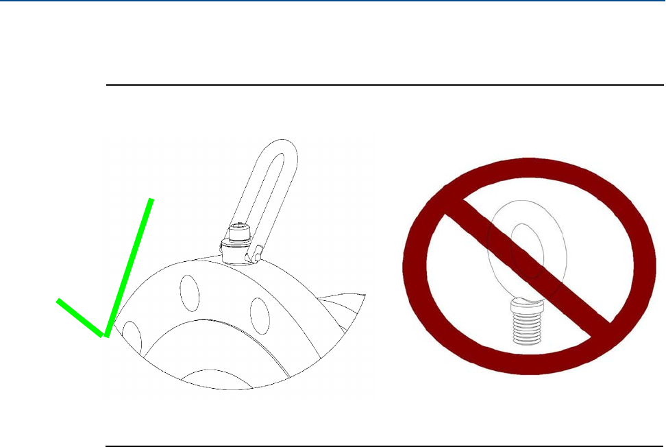
Engineered Swivel Hoist Ring as shown in Figure 2-9.
Operators SHALL NOT use Eye Bolts (see Figure 2-9) in the Daniel Ultrasonic Meter flange tapped
holes to aid in lifting or maneuvering the unit.
Operators SHALL NOT use other Hoist Rings that do not fully seat flush with the counter bore on
the top of the meter flanges.
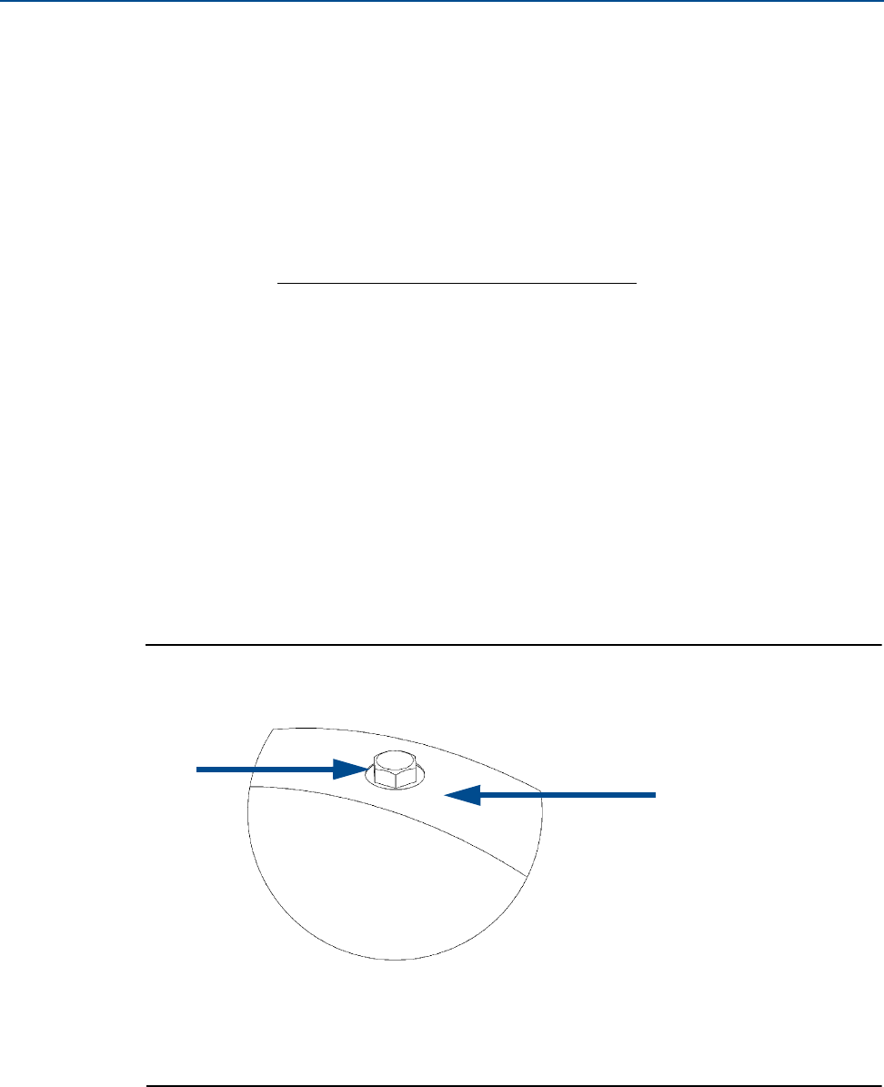
Figure 2-8 Meter end flange with tapped flat-counterbore hole for hoist ring
A. Plug Bolt
B. Flat Counterbore Surface
A.
B.
Daniel 3410 Series Ultrasonic Gas Flow Meter Installation Manual Section 2: Mechanical installation
3-9000-759 Rev D June 2014
Use of appropriate safety engineered swivel hoist rings in meter end flanges 35
Figure 2-9 Safety approved hoist ring and non-compliant eye bolt
Safety precautions using safety engineered swivel hoist rings
Read and follow the Safety Precautions listed below:
1. Meters must only be lifted by personnel properly trained in the safe practices of rigging
and lifting.
2. Remove the plug bolts installed in the tapped holes on the top of the flanges. Do not
discard the bolts as they must be reinstalled once the lifting operation is complete to
prevent corrosion of the tapped holes.
3. Make sure the tapped holes on the meter are clean and free of debris before installing
the hoist rings.
4. Use only the safety engineered swivel hoist rings that are rated for lifting the meter. Do
not use any other type of hoist rings with the same screw size or heavy duty hoist rings.
The meter tapping and counter bore size are suitable only for the hoist rings specified
by Daniel.
5. When installing a hoist ring, make sure the base surface of the hoist ring fully contacts
the machined flat surface of the tapped hole. If the two surfaces do not come in contact
then the hoist ring will not hold its full rated load. Torque the hoist ring attachment
bolts to the limit indicated on the hoist rings.
Eye bolt
Safety engineered swivel hoist ring
36 Use of appropriate safety engineered swivel hoist rings in meter end flanges
Section 2: Mechanical installation Daniel 3410 Series Ultrasonic Gas Flow Meter Installation Manual
June 2014 3-9000-759 Rev D
6. After installation of the hoist rings, always check that the ring rotates and pivots freely
in all directions.
7. NEVER attempt to lift the meter using only one hoist ring.
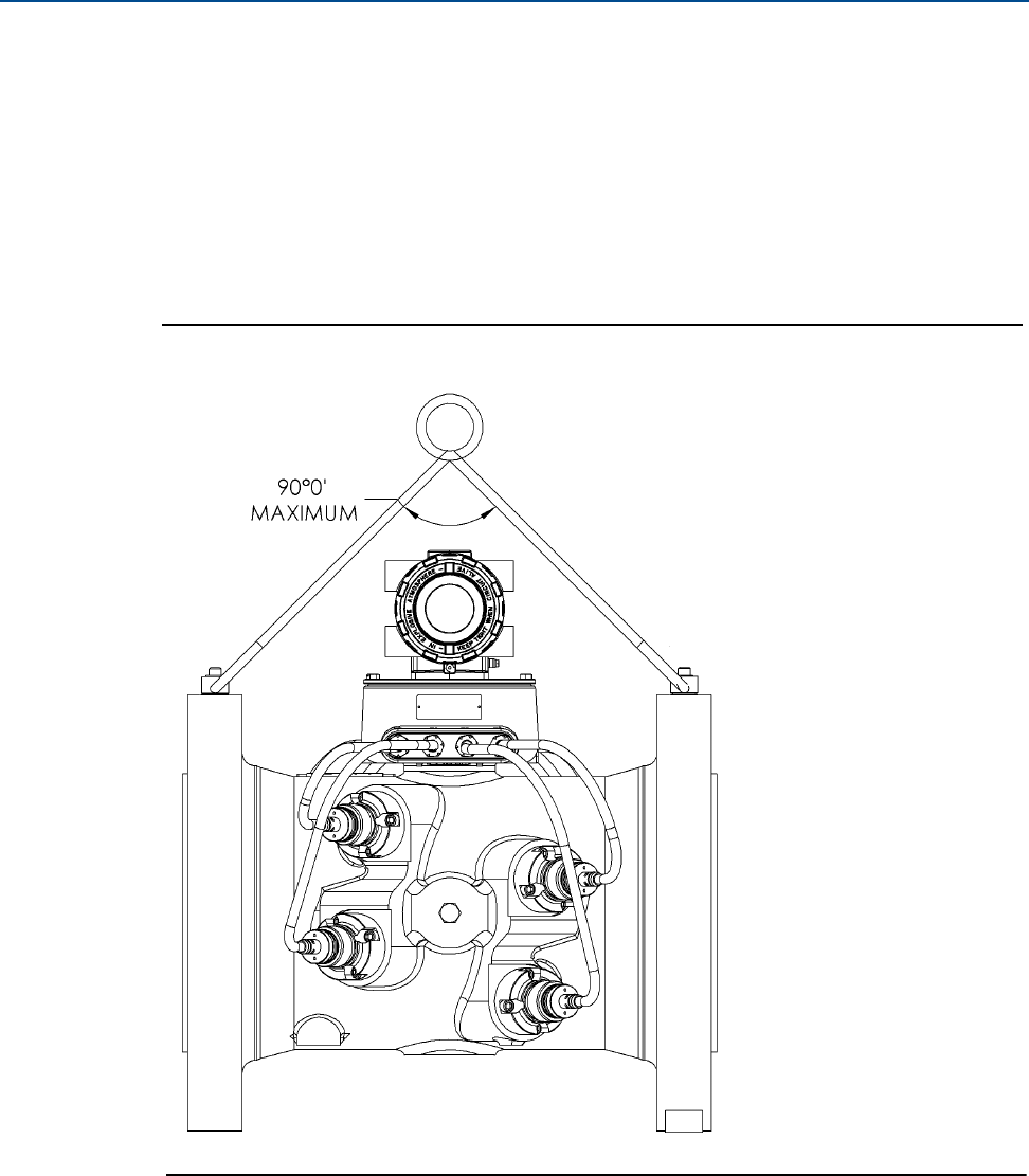
8. Always use separate slings to each hoist ring. NEVER reeve one sling through both hoist
rings. The slings must be of equal length. Each sling must have a load rating that equals
or exceeds the hoist ring load rating. The angle between the two slings going to the
hoist rings must never exceed 90 degrees or the load rating of the hoist rings will be
exceeded.
Figure 2-10 90 Degree angle between slings
Daniel 3410 Series Ultrasonic Gas Flow Meter Installation Manual Section 2: Mechanical installation
3-9000-759 Rev D June 2014
Use of appropriate safety engineered swivel hoist rings in meter end flanges 37
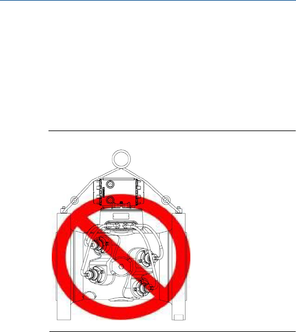
9. NEVER allow the slings to contact the electronics enclosure. Damage to the enclosure
may occur. Use a spreader bar with the slings to prevent contact with the electronics
enclosure and the base enclosure (see Figure 2-12). If the slings do come in contact
with the electronic enclosure then remove the two bolts holding the enclosure to its
base and temporarily remove the head from the meter during the lifting operation. You
will need to unplug the cable from J3 on the Acquisition Module. Two screws hold this
cable in place.
Once the lifting operation is complete, reattach and secure the electronics cable to J3
on the Acquisition Module, return the electronics enclosure to its original position,
replace the bolts, and secure the enclosure in place.
Lifting the meter with the upper enclosure installed but without the bolts installed, may
cause the electronics to fall and cause personal injury or equipment damage.
Figure 2-11 Incorrect sling attachment
10. NEVER apply shock loads to the meter. Always lift the meter gradually. If shock loading
ever occurs, the hoist ring must be inspected per manufacturer's recommendations
prior to any further service. If a proper inspection cannot be performed, discard the
hoist ring.
11. NEVER lift with any device, such as hooks, chains, or cables that could create side pulls
that could damage the ring of the hoist ring.
38 Use of appropriate safety engineered swivel hoist rings in meter end flanges
Section 2: Mechanical installation Daniel 3410 Series Ultrasonic Gas Flow Meter Installation Manual
June 2014 3-9000-759 Rev D
12. NEVER lift more than the ultrasonic meter assembly including electronics and
transducers with the hoist rings. The only exception that safe is to lift the meter with
one ASME B16.5 or ASME B16.47 blind flange bolted to each end flange of the meter.
NEVER use the hoist rings on the meter to lift other components such as meter tubes,
piping or fittings attached to the meter. Doing so will exceed the load rating of the hoist
rings.
13. Remove the hoist rings from the meter after lifting is completed and store them in an
appropriate case or container per their manufacturer's recommendation.
14. Apply heavy lubricant or anti-seize to the threads of the plug bolts and reinstall the plug
bolts to keep the tapped holes free of debris and to prevent corrosion.
How to obtain safety engineered swivel hoist rings
TA list of approved manufacturers of safety engineered hoist rings is below:
•American Drill Bushing Company(www.americandrillbushing.com)
•Carr Lane Manufacturing Company (www.carrlane.com)
Select an approved supplier from the list below. These vendors can supply the safety-
engineered hoist rings. This is not intended to be a complete list.
•Fastenal (www.fastenal.com)
•Reid Tools (www.reidtool.com)
The appropriate hoist rings can also be purchased directly from Daniel. The following table
provides part numbers for reference:
Table 2-1 Hoist ring part number lookup table
Daniel part
number1
1. Note: The part numbers include only one hoist ring. Two hoist rings are required per meter.
Hoist ring thread size &
load rating 1
American Drill
Bushing Co. P/N 1Carr Lane Manufacturing Co. P/N 1
1-504-90-091 3/8”-16UNC, 1000 lb. 23053 CL-1000-SHR-1
1-504-90-092 1/2”-13UNC, 2500 lb 23301 CL-23301-SHR-1
1-504-90-093 3/4”-10UNC, 5000 lb. 23007 CL-5000-SHR-1
1-504-90-094 1”-8UNC, 10000 lb. 23105 CL-10000-SHR-1
1-504-90-095 1-1/2”-6UNC, 24000 lb. 23202 CL-24000-SHR-1
Daniel 3410 Series Ultrasonic Gas Flow Meter Installation Manual Section 2: Mechanical installation
3-9000-759 Rev D June 2014
Use of appropriate safety engineered swivel hoist rings in meter end flanges 39
What size safety engineered swivel hoist ring do you need?
To determine the size of the hoist rings required for your meter, use the appropriate table below.
Look down the column that matches the ANSI rating of your meter. Find the row that contains
your meter size. Follow the row to the end to find the appropriate hoist ring part number.
Table 2-2 Hoist Ring Lookup Table for Daniel 3414 Gas Meters1
1. 4” to 6” 45 degree meters and 8” to 36” 60 degree meters.
ANSI 300 ANSI 600 ANSI 900 ANSI 1500 Daniel Part Number
4” to 10” 4” to 8” 4” to 8” 4” to 6” 1-504-90-091
12” to 18” 10” to 16” 10” to 12” 8” to 10” 1-504-90-092
20” to 24” 18” to 20” 16” to 20” 12” 1-504-90-093
30” to 36” 24” to 30” 24” 16” to 20” 1-504-90-094
36” 30" to 36” 24" to 36” 1-504-90-095
Table 2-3 Hoist Ring Lookup Table for Daniel 3411 or 3412 Gas Meters
ANSI 300 ANSI 600 ANSI 900 ANSI 1500 Daniel Part Number
4” to 10” 4” to 8” 4” to 8” 4” to 6” 1-504-90-091
12” to 18” 10” to 16” 10” to 12” 8” to 10” 1-504-90-092
20” to 24” 18” to 20” 16” to 20” 12” 1-504-90-093
30” to 36” 24” to 30” 24” 16” to 20” 1-504-90-094
36” 30" to 36” 24" to 36” 1-504-90-095

40 Appropriately rated lifting slings
Section 2: Mechanical installation Daniel 3410 Series Ultrasonic Gas Flow Meter Installation Manual
June 2014 3-9000-759 Rev D
2.4.2 Appropriately rated lifting slings
The following instructions are intended to provide general guidelines for using proper lifting
slings when lifting a Daniel 3410 Series Gas Ultrasonic Flow Meter by itself. These instructions
are intended to be followed in addition to your company's standards or the DOE-STD-1090-
2004 Hoisting and Rigging standard if such company standards do not exist.
Safety precautions using appropriate rated lifting slings
1. Meters must only be lifted by personnel properly trained in the safe practices of rigging
and lifting.
2. NEVER attempt to lift the meter by wrapping slings around the electronics enclosure.
3. NEVER attempt to lift the meter using only one sling around the meter. Always use two
slings wrapped around each end of the body as shown below. A choker style sling is
recommended.
Figure 2-12 Correct sling attachment

Daniel 3410 Series Ultrasonic Gas Flow Meter Installation Manual Section 2: Mechanical installation
3-9000-759 Rev D June 2014
Appropriately rated lifting slings 41
4. Visually inspect the slings prior to use for any signs of abrasion or other damage. Refer
to the sling manufacturer's procedures for proper inspection of the particular sling you
are using.
5. Only use slings with ratings that exceed the weight to be lifted. Reference your
company's standards for safety factors that must be included when calculating the load
rating.
6. NEVER allow the slings to contact the electronics enclosure or the transducer cabling.
Damage to the meter may occur. If the slings do come in contact with the electronics
enclosure, then remove the two bolts holding the enclosure to its base and temporarily
remove the head from the meter during the lifting operation (Remove the two bolts
holding the enclosure to its base and unplug the cable from the Acquisition Module.
Two screws hold this cable in place.) Use a spreader-bar on the slings to prevent contact
with the electronics.
7. Once the lifting operation is complete, reattach and secure the electronics cable to J3
on the Acquisition Module, return the electronics enclosure to its original position,
replace the bolts, and secure the enclosure in place. Lifting the meter with the upper
enclosure installed but with out the bolts installed, may cause the electronics to fall and
cause personal injury or electronics damage.
Figure 2-13 Incorrect sling attachment
8. NEVER apply shock loads to the meter. Always lift the meter gradually. If shock loading
ever occurs, the slings must be inspected per manufacturer's procedures prior to being
placed in any further service.
42 Mounting requirements in heated or cooled pipelines
Section 2: Mechanical installation Daniel 3410 Series Ultrasonic Gas Flow Meter Installation Manual
June 2014 3-9000-759 Rev D
2.5 Mounting requirements in heated or cooled
pipelines
The ambient operating temperature of the Daniel 3410 Series Gas Ultrasonic Flow Meter
electronics (i.e. Flameproof enclosure and Intrinsically safe base enclosure) is -40 oF (-40 oC) to
+140 oF (+60 oC). If the meter is installed into a pipeline which is heated or cooled outside this
temperature range it is necessary to remove the electronics housing from the meter body (i.e.
Spool piece acting as process fluid conduit) and mount it next to the meter body on a pipe stand
or other rigid structure.
Extended length transducer cables (P/N 2-3-3400-194, 15 ft. long) shall be used to connect the
Daniel 3410 Series Gas Ultrasonic Flow Meter electronics to the transducers installed in the
meter body. The process temperature must also not exceed the operating temperature range of
the transducers. T-11, T-12 and T-21 transducers have an operating range from -4 oF (-20 oC)
to 212 oF (+100 oC). T-22 transducers have an operating range from -58 oF (-50 oC) to
212 oF (+100 oC).
SURFACE TEMPERATURE HAZARD
The meter body and piping may be extremely hot or cold.
Wear appropriate personal protective equipment when coming in contact with the meter.
Failure to do so may result in injury.

Daniel 3410 Series Ultrasonic Gas Flow Meter Installation Manual Section 3: Electrical installation
3-9000-759 Rev D June 2014
Cable length TTL mode 43
Section 3: Electrical installation
3.1 Cable length TTL mode
The maximum cable length is 2000 feet when the Digital Output “TTL” mode is selected.
3.2 Cable length Open Collector mode
For the Digital Output “open collector” mode, the maximum cable length depends on the cable
parameters, pull-up resistance used, the maximum frequency to output, and frequency input
parameters being driven. The following table provides estimated cable lengths for different pull-
up resistor values and different Max Frequency settings in the meter using the following cable
parameters. The table also provides an estimated cable voltage drop which indicates how much
voltage will be across the cabling and effectively indicates to what voltage level the frequency
input can be pulled down to by the frequency output.
If the voltage drop is higher than the voltage required for the frequency input to see a low state,
then the configuration will most likely not work for your system. Performance of frequency
outputs will vary from this table with setup and frequency input being driven.
The 22 AWG wire characteristics:
•Capacitance = 20 pF/ft or 20 nF/1000 ft (between two wires)
•Resistance = 0.0168 Ohms/ft or 16.8 Ohms/1000 ft
•Pull-up voltage = 24 VDC
Table 3-1 Configurations for open collector frequency outputs
Cable
Cable
resistance Cable
Pull-up
resistance Total
Maximum
frequency Sink
Cable voltage
drop
Length (2 Conductors) Capacitance Resistance Resistance Frequency Current (2 Conductors)
(x1000ft) nF (Hz) (A) VDC
0.5 16.8 10.00 1000 1016.8 5000 0.024 0.397
1 33.6 20.00 1000 1033.6 1000 0.023 0.780
2 67.2 40.00 1000 1067.2 1000 0.022 1.511
4 134.4 80.00 1000 1134.4 1000 0.021 2.843
0.5 16.8 10.00 500 516.8 5000 0.046 0.780
1 33.6 20.00 500 533.6 5000 0.045 1.511
1.7 57.12 34.00 500 557.12 5000 0.043 2.461
6.5 218.4 130.00 500 718.4 1000 0.033 7.296
Ω
Ω
Ω
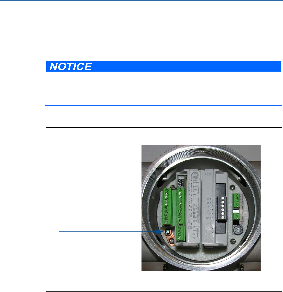
44 GROUNDING METER ELECTRONICS HOUSING
Section 3: Electrical installation Daniel 3410 Series Ultrasonic Gas Flow Meter Installation Manual
June 2014 3-9000-759 Rev D
3.3 Grounding meter electronics housing
The meter electronics should be internally grounded for intrinsically safe operations. Connect a
wire to the chassis ground lug installed inside the Transmitter Electronics Enclosure as the
primary ground. A secondary ground is located outside of the Transmitter Electronics Enclosure
(see Figure 3-2).
Figure 3-1 Internal Transmitter Electronics Enclosure chassis ground
The internal grounding terminal shall be used as the primary equipment ground. The
external terminal is only a supplemental bonding connection where local authorities permit
or require such a connection. DO NOT connect digital grounds to the ground lugs.
A. Transmitter Electronics Enclosure ground lug
A.
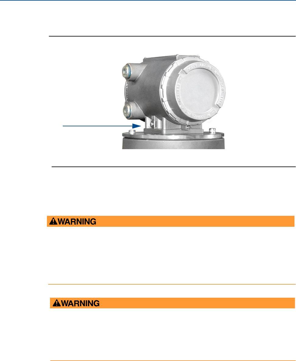
Daniel 3410 Series Ultrasonic Gas Flow Meter Installation Manual Section 3: Electrical installation
3-9000-759 Rev D June 2014
Conduit seals 45
Figure 3-2 External ground lug
3.4 Conduit seals
Conduit seals are required for meter installations in hazardous environments. Adhere to safety
instructions to protect personnel and equipment.
A.
A. External ground lug
EXPLOSION HAZARD
To reduce the risk of an explosion or fire, conduit runs must have a sealing fitting connected
within 457.2 mm (18 inches) of the enclosure. Substitution of components may impair
intrinsic safety of the meter.
Failure to keep covers tight during operation may result in serious injury or death.
EXPLOSION HAZARD
Substitution of components may impair the intrinsic safety and cause ignition of flammable
or combustible atmospheres. Disconnect power before servicing.
Failure to remove power and use Daniel approved components may cause serious injury.

46 STARTUP FOR SYSTEMS USING EXPLOSION-PROOF CONDUIT
Section 3: Electrical installation Daniel 3410 Series Ultrasonic Gas Flow Meter Installation Manual
June 2014 3-9000-759 Rev D
3.4.1 Startup for systems using explosion-proof conduit
1. Assemble conduit to the Transmitter Electronics Enclosure. A conduit seal fitting is
required within 18 inches (457 mm) of the enclosure.
2. Check to make certain that all power to field wiring is turned OFF.
3. Remove the end cap nearest the conduit entry to gain access to the transmitter
electronics.
4. Pull the wires into the electronics enclosure.Complete the field connection wiring as
shown in see Figure 3-3 and Section 3.5.
HAZARDOUS VOLTAGE INSIDE
Do not open the Transmitter Electronics Enclosure when an explosive gas atmosphere is
present. Disconnect equipment from supply circuit before opening the enclosure.
Failure to remove power may result in serious injury or death.
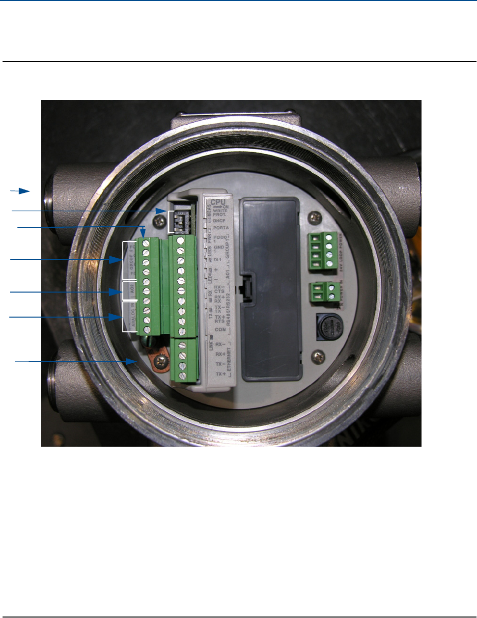
Daniel 3410 Series Ultrasonic Gas Flow Meter Installation Manual Section 3: Electrical installation
3-9000-759 Rev D June 2014
Startup for systems using explosion-proof conduit 47
5. Complete the field connection wiring and apply electrical power to the system.
Figure 3-3 Electronics field wiring - upper terminal block, switches, ground lug
A.
A. Conduit wiring entry (four entries)
Switches:
C. Upper terminal block
D. FODO Group 2
B.
C.
G.
B.
FODO2
GND2
FODO3
E. Analog Out (Current 4-20mA)
AO2+
AO2 -
1. Port A
2. DHCP
3. WRITE PROT.
Analog In (AO1)
Analog Input 1 (Temperature)
TT+
TT -
PT+
PT -
Analog In (AO2)
Analog Input 2 (Pressure)
D.
E.
F.
F. Analog In
Upper terminal block (continued)
G. Ground lug

48 STARTUP FOR SYSTEMS USING EXPLOSION-PROOF CONDUIT
Section 3: Electrical installation Daniel 3410 Series Ultrasonic Gas Flow Meter Installation Manual
June 2014 3-9000-759 Rev D
Figure 3-4 Transmitter electronics field wiring lower terminal block
F.
G.
H.
A. Upper terminal block
B. FODO Group 1 connections
FODO1
GND1
DI 1
E. Ethernet
Ethernet (orange and white wire)
Ethernet (orange wire)
Ethernet (green and white wire)
Ethernet (green wire)
C. AO1
AO1+
AO1 -
D. Serial COMs (RS-232, RS-485)
RS-232: RTS, TX, RX, CTS
RS-485: TX+, TX -, RX+, RX - (4-wire Full Duplex )
B.
C.
D.
E.
A.
RS-485: TX+, TX- (2-wire Half Duplex)
F. 24V loop power (4-24mA inputs/outputs)
G. Power In (104VDC - 36VDC)
H. Fuse cover

Daniel 3410 Series Ultrasonic Gas Flow Meter Installation Manual Section 3: Electrical installation
3-9000-759 Rev D June 2014
Startup for systems using explosion-proof conduit 49
6. Set or configure the meter operating parameters using Daniel MeterLink. For additional
installation information refer to the system wiring diagram (see Appendix A), Daniel
MeterLink Software for Gas and Liquid Ultrasonic Meters Quick Start Manual
(P/N 3-9000-763) and use the Daniel MeterLink Field Setup Wizard to complete the
configuration.
7. Verify the field connections are working correctly. Allow the system to run for the time
specified by the customer (usually one week) and an electrician has fully tested the
connections. After the Acceptance Test is witnessed and approved, seal the conduit.
8. Power down the system and apply the sealing compound to the conduit and allow to
set in accordance with manufacturer specifications.
9. If required, install the security latches and wire seals on the Transmitter Electronics
Enclosure end caps (see Section 3.7 and Figure 3-11).
10. If required, install the wire seals through the socket head bolts on the Base Enclosure
(see Section 3.7, Figure 3-12 and Figure 3-13).
11. Re-apply electrical power to the system.

50 STARTUP FOR SYSTEMS THAT USE FLAME-PROOF CABLE
Section 3: Electrical installation Daniel 3410 Series Ultrasonic Gas Flow Meter Installation Manual
June 2014 3-9000-759 Rev D
3.4.2 Startup for systems that use flame-proof cable
1. Check to make certain that all field wiring power is turned OFF.
2. Remove the end cap nearest the cable entries to gain access to the transmitter
electronics.
3. Install the cable and cable gland.
4. Complete the field connection wiring and apply electrical power to the system.
5. Set or configure the meter operating parameters using Daniel MeterLink. For additional
installation information refer to the system wiring diagram (see Appendix A), Daniel
MeterLink Software for Gas and Liquid Ultrasonic Meters Quick Start Manual
(P/N 3-9000-763) and use the Daniel MeterLink Field Setup Wizard to complete the
configuration.
6. Verify the field connections are working correctly. Allow the system to run for the time
specified by the customer (usually one week) and an electrician has fully tested the
connections. After the Acceptance Test is witnessed and approved, seal the conduit.
7. Power down the system and apply the sealing compound to the conduit and allow to
set in accordance with manufacturer specifications.
8. If required, install the security latches and wire seals on the Transmitter Electronics
Enclosure end caps (see Section 3.7 and Figure 3-11).
9. If required, install the wire seals through the socket head bolts on the Base Enclosure
(see Section 3.7, Figure 3-12 and Figure 3-13).
10. Re-apply electrical power to the system.
HAZARDOUS VOLTAGE INSIDE
Do not open the Transmitter Electronics Enclosure when an explosive gas atmosphere is
present. Disconnect equipment from supply circuit before opening the enclosure.
Failure to remove power may result in serious injury or death.

Daniel 3410 Series Ultrasonic Gas Flow Meter Installation Manual Section 3: Electrical installation
3-9000-759 Rev D June 2014
Wiring and I/O 51
3.5 Wiring and I/O
Daniel MeterLink uses the TCP/IP protocol to communicate with the Daniel 3410 Series
Ultrasonic Gas Flow Meter electronics instead of Modbus ASCII or RTU. The TCP/IP protocol only
works across either Ethernet, RS-485 full duplex (4-wire) or RS-232. Daniel MeterLink can
communicate with multiple meters if they are multi-dropped using 4-wire, full duplex RS-485
mode. The meter electronics is HART capable and provides communication flexibility with
Daniel 3410 Series Gas Ultrasonic Flow Meters.
Note: Port B for RS-485 full duplex communication is not supported.
The HART® output provides communication with other field devices (e.g., Field Communicator
and AMS™ Device Manager software) and ultimately, communicates key diagnostic information
through PlantWeb® architecture.
The Daniel 3410 Series Gas Ultrasonic Flow Meter electronics auto-detects the protocol used
and automatically switches between TCP/IP, Modbus ASCII, and Modbus RTU so it is not
necessary to make any meter configuration changes to the protocol.
If not using Ethernet, a full duplex serial connection is necessary for Daniel MeterLink to
communicate with a Daniel 3410 Series Gas Ultrasonic Meter.
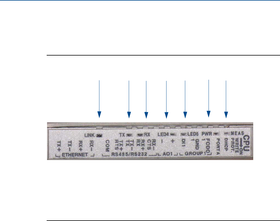
52 CPU MODULE LABELING AND LED INDICATORS
Section 3: Electrical installation Daniel 3410 Series Ultrasonic Gas Flow Meter Installation Manual
June 2014 3-9000-759 Rev D
3.5.1 CPU Module labeling and LED indicators
The meter’s metrology mode and the status of the data transfer from the Acquisition Module to
the CPU Module are indicated via light-emitting diode (LED) status indicators. The WRITE PROT.
switch protects the meter’s configuration,
Figure 3-5 CPU Module labeling and LED indicators
A.
B.
C. D. E.
A. Acquisition/Measurement mode
B. Power
C. RX (RS-485/RS-232) - receiving data
D. LED 4 - not used
E. LED 5 - not used
F. TX (RS-485/RS-232) - transmitting data (RS-485 2-wire use TX+ and TX-)
F.
G.
G. Link (Eth1 Link) - user Ethernet connection

Daniel 3410 Series Ultrasonic Gas Flow Meter Installation Manual Section 3: Electrical installation
3-9000-759 Rev D June 2014
CPU Module labeling and LED indicators 53
Table 3-2 CPU Module labeling and LED functions
CPU Module label
or LED Function Switch position indicator or LED
WRITE PROT. •Write-protect mode - with switch in the ON
position (default setting) protects configuration
and firmware overwrites.
•To write configuration changes or download
firmware to the meter change the switch to the
OFF position
Switch position
•ON - (default setting) enables write-
protection of the configuration and
firmware
•OFF - enables writing configuration
changes or downloading firmware
DHCP •Dynamic Host Protocol Server - enables you to
communicate with a Daniel meter that is not
connected to a network.
•When the CPU Module switch is in the ON
position, the meter is enabled to act as a DHCP
server for a single DHCP client connected to the
Ethernet port using a crossover cable. This should
be used for peer to peer connections only.
•When the connection is made, select to use the
Meter Name in the meter instead of the Meter
Directory Name in order to keep all log files and
configurations separate from each meter.
Switch position
•ON - the meter is enabled to act as a
DHCP server for a single DHCP client
•OFF - disables the DHCP server
PORT A •PORT A override - RS-232 serves as an override
during meter commissioning to establish com-
munications and in the event the user cannot
communicate with the meter due to an inadver-
tent communication configuration change. The
override period is for two minutes.
•Supports:
–auto-detected ASCII (Start bit 1, Data Bit 7,
Parity Odd/Even, Stop Bit 1)
–RTU (Start Bit 1, Data Bit 8, Parity none, Stop
Bit 1).
–Modbus protocols
•RS-232 Baud rate=19,200
•Modbus ID=32
Switch position
•ON - enables RS-232 PORT A override
•OFF - (default setting) disables
RS-232 PORT A override
MEAS System color indicates metrology mode
•Acquisition mode
•Measurement mode
LED status
•Red flashing LED
•Solid red the Acquisition Module is not
communicating with the CPU Module
•Green flashing LED
PWR •3.3V Power Indicator •Solid Green
LED 4 •Not used
LED 5 •Not used
RX •RX signal (Port A for RS485 or RS232 )
communication) receiving data
•Flashing green (when receiving data)
TX •TX signal (Port A for RS485; 2-wire or 4-wire) or
RS232
communication) transmitting data
•Flashing green (when transmitting
data)
LINK •ETH1Link user Ethernet connection •Solid green
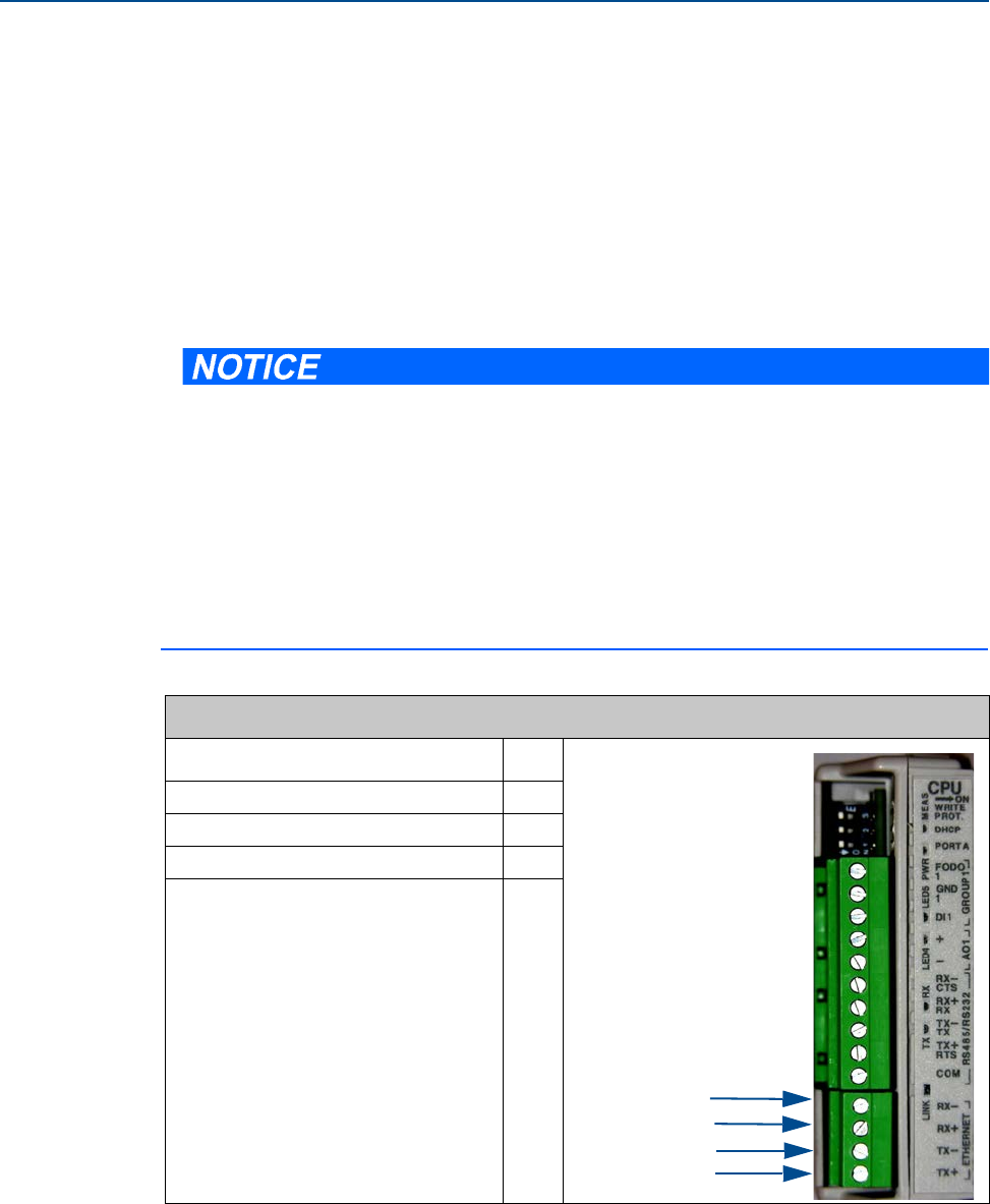
54 CPU MODULE LABELING AND LED INDICATORS
Section 3: Electrical installation Daniel 3410 Series Ultrasonic Gas Flow Meter Installation Manual
June 2014 3-9000-759 Rev D
Ethernet communications
The Ethernet port IP address, subnet mask, and gateway address are software-configurable. In
addition, a meter can be configured to act as a DHCP (Dynamic Host Configuration Protocol)
server to assign an IP address to a PC or laptop running Daniel MeterLink. The DHCP server
facility is not intended to act as a general purpose DHCP server for a wider network. To this end,
no user control is provided over the class or range of IP addresses the unit provides. A standard
twisted pair (Cat-5) cable should be used for Ethernet wiring.
It is strongly recommended that the meter be configured using an independent (off-network)
single host. After configuration of the Daniel 3410 Series Gas Ultrasonic Flow Meter, the DHCP
option must be turned off if used on a LAN/WAN.
Use ethernet cable, Daniel P/N 3-3400-079, to connect the PC to the meter.
A DIN 41612 48-pin connector is the interface from the CPU Module to the Field Connection
Board (male end located on the back of the Field Connection Board).
Table 3-3 Ethernet cable to PC communication
Ethernet communication
Wire color CPU
White w/Orange Stripe TX+
Orange w/White Stripe TX -
White w/Green Stripe RX+
Green w/White Stripe RX -
RESTRICTED ETHERNET AND SERIAL CONNECTIVITY USAGE
Failure to restrict Ethernet and communication access to the Daniel 3410 Series Gas
Ultrasonic Flow Meter can result in, among other things, unauthorized access, system
corruption, and/or data loss.
User is responsible for ensuring that physical access and Ethernet or electronic access to the
Daniel 3410 Series Gas Ultrasonic Flow Meter is appropriately controlled and any necessary
security precautions are implemented; such as, establishing a firewall, setting password
permissions and/or implementing security levels.
RX+
TX+
TX -
RX -

Daniel 3410 Series Ultrasonic Gas Flow Meter Installation Manual Section 3: Electrical installation
3-9000-759 Rev D June 2014
CPU Module labeling and LED indicators 55
Modbus TCP
If the meter firmware supports Modbus TCP slave functionality, the following controls will be
available.
Modbus TCP unit identifier: Enter the Modbus TCP unit identifier here. Valid values are 0-255.
Enable alternate Modbus TCP port: The standard TCP port for Modbus TCP is port 502. This port
is always enabled in a meter that supports Modbus TCP. By selecting this option, you can also
enable Modbus TCP communications on a secondary TCP port specified by Alternate Modbus
TCP port.
Alternate Modbus TCP port:
Enter the alternate TCP port number here after selecting Enable alternate modbus TCP port.
Valid port numbers are from 1 to 65535. The meter will not allow some port numbers that are
either used by the meter or are defined port numbers for other protocols. Daniel MeterLink™
will prompt you if it was not able to write the specified port number to the meter.

56 CPU MODULE LABELING AND LED INDICATORS
Section 3: Electrical installation Daniel 3410 Series Ultrasonic Gas Flow Meter Installation Manual
June 2014 3-9000-759 Rev D
Serial connections
Use a serial cable, Daniel P/N 3-2500-401, to connect to a PC running Daniel MeterLink. The
cable is designed for RS-232 communications which is the serial Port A default configuration
(see Appendix A field wiring diagram, Daniel Drawing DMC - 005324). The DB-9 end of the cable
plugs directly into the PC running Daniel MeterLink. The three wires on the other end of the
cable connect to the CPU Module RS-485/RS-232 terminals. The RED wire goes to RX, the
WHITE wire goes to TX, and the BLACK wire goes to COM (see Table 3-6 for Port A wiring).
RS-485, 2-wire connection on Port A, uses TX+ and TX- on the CPU Module and has a ground
wire.
When Beldon wire No. 9940 or equivalent is used, the maximum cable length for RS-232
communications at 9600 bps is 88.3 meters (250 ft.) and the maximum cable length for RS-485
communication at 57600 bps is 600 meters (1970 ft.).
Port A supports a special override mode which forces the port to use known communication
values (19200 baud, address 32, RS-232). Note that the protocol is auto-detected. This mode is
expected to be used during meter commissioning (to establish initial communication) and in
the event that the user cannot communicate with the meter (possibly due to an inadvertent
communication configuration change). Alternately, when using Daniel MeterLink with an
Ethernet port, use Ethernet cable, Daniel P/N 3-3400-079, to connect the PC.
Table 3-4 Serial Port A parameters
Port/Communication Description Common features
Port A (Standard)
•RS-232
•RS-485 Half Duplex
•RS-485 Full Duplex
•RS-4851 (2-wire
communication on
Port A.)
1. RS-485 2-wire connections use TX+ and TX - on the CPU Module
•Typically used for general communications with
a flow computer, RTU (Modbus slave) and
radios.
•RS-485 — 2-wire (Half Duplex) connected to
TX+ and TX -
•Special override mode to force port configura-
tion to known settings.
•Supports RTS/CTS handshaking with software-
configurable RTS on/off delay times.
•Factory default is RS-232, Address 32, 19200
baud.
•Communications via Daniel MeterLink
using RS-232 or RS-485 Full Duplex
•Software configurable Modbus
Address (1-247)
•Auto-detects TCP/IP and ASCII or RTU
Protocol
–ASCII Protocol:
Start Bits = 1, Data Bits = 7 2
–Parity: odd or even 1, Stop Bits = 12
–Baud Rates: 1200, 2400, 9600,
19200, 38400, 57600, 115000 bps
–RTU Protocol:
Start Bits = 1, Data Bits = 82
–Parity: none, Stop Bits = 12
–Baud Rates: 1200, 2400, 9600,
19200, 38400, 57600, 115000 bps
Ethernet •Preferred port for diagnostic communication
via Daniel MeterLink
•10 Mbps/100 Mbps
•Modbus TCP/IP, Modbus TCP

Daniel 3410 Series Ultrasonic Gas Flow Meter Installation Manual Section 3: Electrical installation
3-9000-759 Rev D June 2014
I/O connections 57
Figure 3-6 PC to meter serial connection wiring
3.6 I/O connections
The Daniel 3410 Series Gas Ultrasonic Flow Meter provides the I/O connections on the CPU
Module.
2. Denotes auto-detected protocols
If not using Ethernet, a full duplex serial connection is necessary for Daniel MeterLink to
communicate with a Daniel 3410 Series Gas Ultrasonic Flow Meter.
RX
TX
COM
DB-9 Connector Female
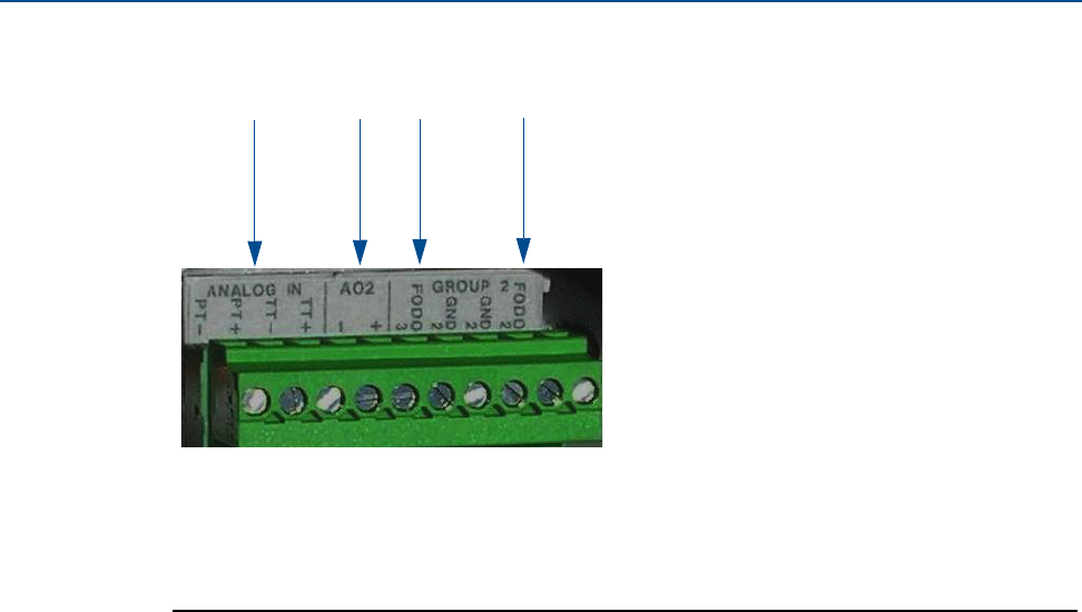
58 I/O CONNECTIONS
Section 3: Electrical installation Daniel 3410 Series Ultrasonic Gas Flow Meter Installation Manual
June 2014 3-9000-759 Rev D
Figure 3-7 CPU Module I/O connections
A.
B.
C.
D.
A. Frequency/Digital Output 2
B. Frequency/Digital Output 3
C. Analog Output 2 - 4-20mA output
D. Analog Input - HART temperature and pressure connections

Daniel 3410 Series Ultrasonic Gas Flow Meter Installation Manual Section 3: Electrical installation
3-9000-759 Rev D June 2014
Frequency/Digital outputs 59
3.6.1 Frequency/Digital outputs
The meter has three user-configurable selections for configuring either a Frequency output or
Digital output (FODO).
•FODO1 (four possible parameter configurations)
•FODO2 (eight possible parameter configurations)
•FODO3 (eight possible parameter configurations)
Frequency or Digital Outputs (FODO 1) source
•FO1A, DO1A, FO1B, DO1B
•Frequency output 1A is based on frequency content (Actual - Uncorrected Flow Rate)
•Frequency output 1B is based on frequency content and Frequency 1 B Phase
•Digital output 1A is based on Digital output1A content (Frequency1A Validity or Flow
Direction)
Frequency or Digital Outputs (FODO 2) source
•FO1A, DO1A, FO1B, DO1B, FO2A, DO2A, FO2B, DO2B
•Frequency output 1A is based on frequency content (Actual - Uncorrected Flow Rate)
•Frequency output 1B is based on frequency content and Frequency 1B Phase
•Frequency output 2A is based on frequency content (Actual - Uncorrected Flow Rate)
•Frequency output 2B is based on frequency content and Frequency 2B Phase
•Digital output 1A is based on Digital output1A content (Frequency 1Validity and Flow
Direction)
•Digital output 1B is based on Digital output1B content (Frequency 1 Validity and Flow
Direction)
•Digital output 2A is based on Digital output 2A content (Frequency 2 Validity and Flow
Direction)
•Digital output 2B is based on Digital output 2B content (Frequency 2 Validity and Flow
Direction)

60 FREQUENCY/DIGITAL OUTPUTS
Section 3: Electrical installation Daniel 3410 Series Ultrasonic Gas Flow Meter Installation Manual
June 2014 3-9000-759 Rev D
Frequency or Digital Outputs (FODO 3) source
•FO1A, DO1A, FO1B, DO1B, FO2A, DO2A, FO2B, DO2B
•FO1A, DO1A, FO1B, DO1B, FO2A, DO2A, FO2B, DO2B
•Frequency output 1A is based on frequency content (Actual - Uncorrected Flow Rate)
•Frequency output 1B is based on frequency content and Frequency 1B Phase
•Frequency output 2A is based on frequency content (Actual - Uncorrected Flow Rate)
•Frequency output 2B is based on frequency content and Frequency 2B Phase
•Digital output 1A is based on Digital output 1A content (Frequency 1 Validity and Flow
Direction)
•Digital output 1B is based on Digital output 1B content (Frequency 1Validity and Flow
Direction)
•Digital output 2A is based on Digital output 2A content (Frequency 2 Validity and Flow
Direction)
•Digital output 2B is based on Digital output 2B content (Frequency 2 Validity and Flow
Direction)
Mode options
•Open Collector (requires external excitation supply voltage and pull-up resistor)
•TTL (internally powered by the meter 0-5 VDC signal)
Channel B Phase options:
•Lag forward, Lead reverse (Phase B lags Phase A while reporting forward flow, leads Phase
A while reporting reverse flow)
•Lead forward, Lag reverse (Phase B leads Phase A while reporting forward flow, lags Phase
A while reporting reverse flow)
Phase A and Phase B output (based on flow direction)
•Reverse flow - output only reports flow in the reverse direction. For frequency outputs,
Phase B of the output is 90 degrees out of phase with Phase A.
•Forward flow - output only reports flow in the forward direction. For frequency outputs,
Phase B of the output is 90 degrees out of phase with Phase A.
•Absolute - output reports flow in both directions. For frequency outputs, Phase B of the
output is 90 degrees out of phase with Phase A.
• Bidirectional - output reports flow on Phase A only in the forward direction and on Phase
B only in the reverse direction.
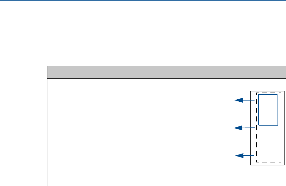
Daniel 3410 Series Ultrasonic Gas Flow Meter Installation Manual Section 3: Electrical installation
3-9000-759 Rev D June 2014
Frequency/Digital outputs 61
Maximum frequency for the frequency outputs
•1000Hz
•5000Hz
Table 3-5 Frequency/Digital Outputs possible configurations
Frequency/Digital output Source configuration
Frequency /Digital Output 11
Frequency /Digital Output 22
or
Frequency /Digital Output 32
1. Solid blue line denotes valid selection for Frequency/Digital Output 1.
2. Black dashed -line denotes valid selections for Frequency/Digital Output 2 and
Frequency/Digital Output 3.
•Frequency output 1A
•Frequency output 1B
•Digital output 1A
•Digital output 1B
•Frequency output 1A
•Frequency output 1B
•Digital output 1A
•Digital output 1B
•Frequency output 2A
•Frequency output 2B
•Digital output 2A
•Digital output 2B
FODO1
FODO2
FODO3
FO1A
FO1B
DO1A
DO2B
FO2A
FO2B
DO2A
DO2B
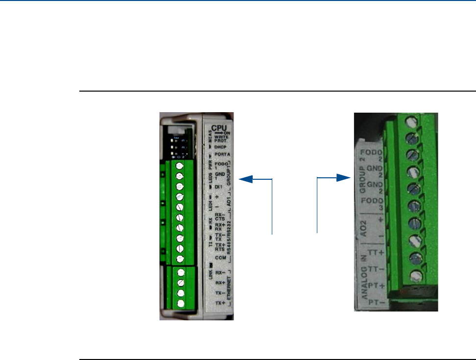
62 ANALOG INPUT SETTINGS
Section 3: Electrical installation Daniel 3410 Series Ultrasonic Gas Flow Meter Installation Manual
June 2014 3-9000-759 Rev D
Output for FODO1 and Digital Output1 (Group 1 on the CPU Module) share a common ground
and have 50V isolation. FODO2 and FODO3 (Group 2 on the CPU Module) share a common
ground and have 50V isolation. This allows an output to be connected to a different flow
computer. The outputs are opto-isolated from the CPU Module and have a withstand voltage of
at least 500V rms dielectric.
Figure 3-8 CPU Module - Frequency/Digital outputs common ground
3.6.2 Analog input settings
The Daniel 3410 Series Gas Ultrasonic Flow Meter has the capability to sample analog
temperature (Analog Input 1) and pressure (Analog Input 2) with 4-20 mA signals. These analog
input signals are configured to sink. The two independent analog input circuits are configured
for conventional 4-20 mA service. Also, 24VDC isolated power supply connection is provided for
an external power source. Refer to the Field wiring diagram DMC - 005324 in Appendix A.
A.
A. FODO1 and Digital input1 - shared common ground (Group 1)
B. FODO2 and FODO3 - shared common ground (Group 2)
B.
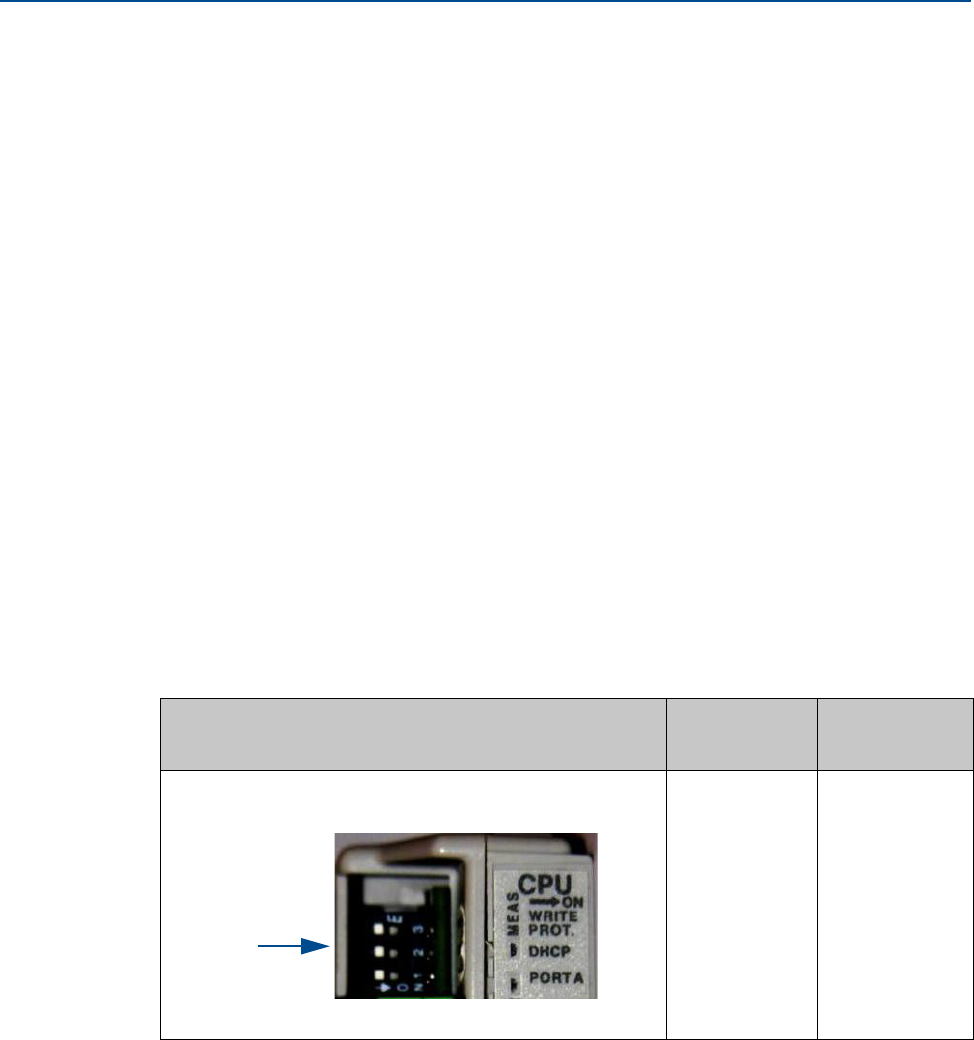
Daniel 3410 Series Ultrasonic Gas Flow Meter Installation Manual Section 3: Electrical installation
3-9000-759 Rev D June 2014
Analog output settings 63
3.6.3 Analog output settings
The Daniel 3410 Series Ultrasonic Gas Flow Meter provides two 4-20 mA analog output signals
that are software configurable for either sink or source current (see Appendix A DMC - 005324).
Full HART® functionality is provided so that any commercially available HART® transmitter
which meets the specifications of the HART® Communications Foundation can be connected to
the Daniel® Liquid Ultrasonic Flow Meter.
•Analog Output1 (AO1) is user-configurable as a 4-20mA output and has HART
capabilities.
•Analog Output 2 (AO2) is user-configurable as a conventional 4-20 mA output.
3.6.4 Digital Input
The Daniel 3410 Series Gas Ultrasonic Flow Meter provides one digital input that can be used as
a general purpose input. The digital input must be configured via the Daniel MeterLink
Tools|Edit/Compare Configuration screen.
3.6.5 DHCP server switch settings
The meter can be configured to act as a DHCP server. The DHCP server is enabled/disabled via
CPU Module DHCP switch as follows:
Table 3-6 DHCP server switch settings
CPU Module switch DHCP server
disabled
DHCP server
enabled
OFF ON
DHCP
Switch 2
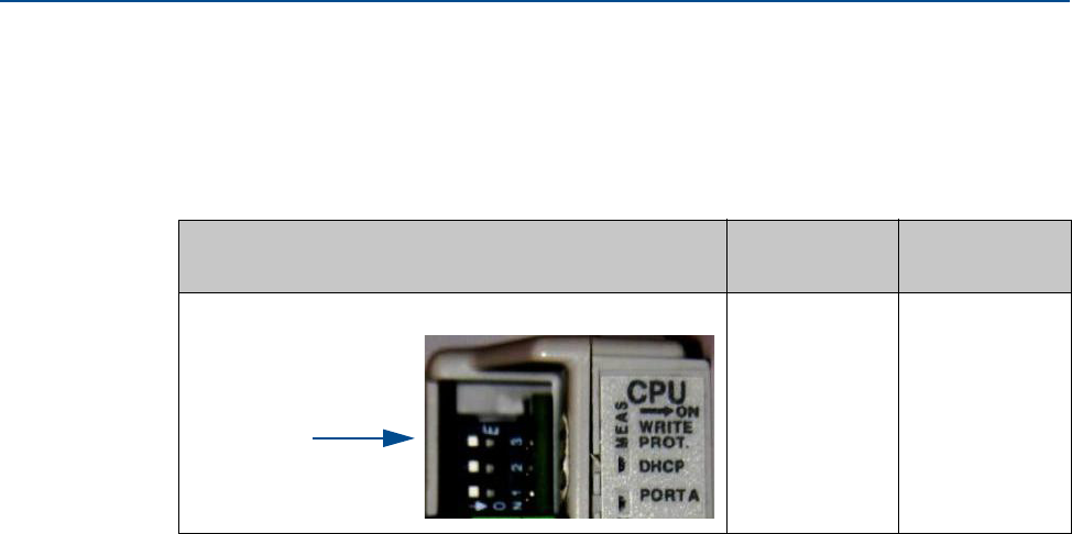
64 CONFIGURATION PROTECT SWITCH SETTINGS
Section 3: Electrical installation Daniel 3410 Series Ultrasonic Gas Flow Meter Installation Manual
June 2014 3-9000-759 Rev D
3.6.6 Configuration protect switch settings
The meter’s configuration parameters and firmware can be protected against changes via the
CPU Module WRITE PROT. switch as follows:
Table 3-7 Configuration protect switch settings
CPU Module switch Configuration
protected
Configuration
unprotected
ON (default
setting)
OFF
WRITE PROT.
Switch 3
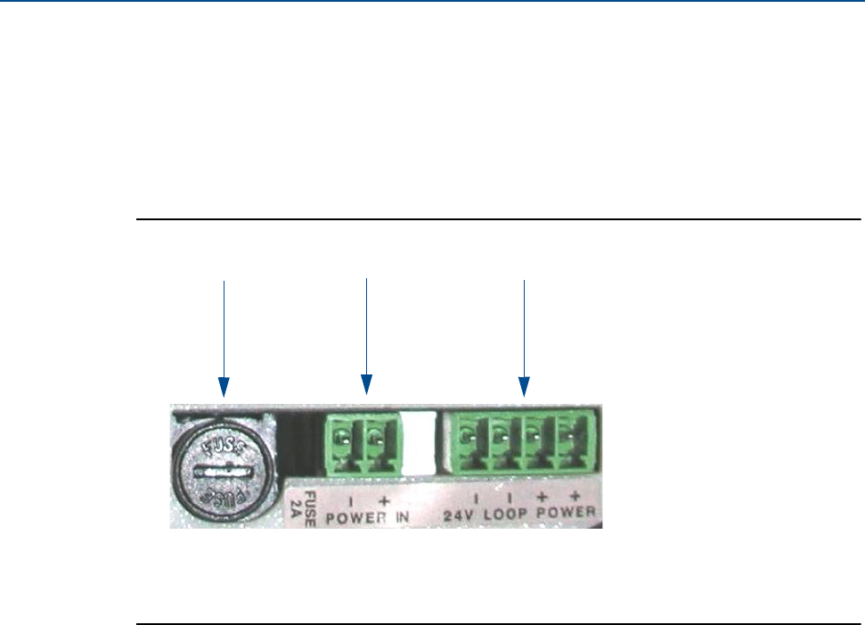
Daniel 3410 Series Ultrasonic Gas Flow Meter Installation Manual Section 3: Electrical installation
3-9000-759 Rev D June 2014
External power source connection and fuse 65
3.6.7 External power source connection and fuse
Located inside the Transmitter Electronics Enclosure is a connector for a user-provided external
power source, a 2 Amp fuse and a 24V loop power connection for ultrasonic meter analog
outputs, temperature transmitter or pressure transmitter devices. The current is limited to
88mA.
Figure 3-9 CPU Module power source connections
A. B.
A. Power In connector (main power)
B. 24V LOOP POWER
C. 2 Amp fuse (used for the main power input)
C.
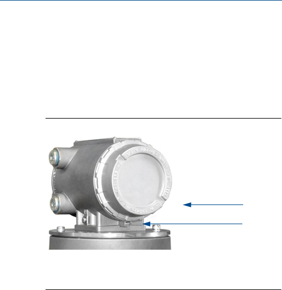
66 SECURITY SEAL INSTALLATION
Section 3: Electrical installation Daniel 3410 Series Ultrasonic Gas Flow Meter Installation Manual
June 2014 3-9000-759 Rev D
3.7 Security seal installation
Security seals protect the integrity of the meter metrology and prevent tampering with
transducer assemblies. The following sections detail how to properly seal the Daniel 3410 Series
Gas Ultrasonic Flow Meter after commissioning. The security seal wires are commercially
available.
Be sure to set the WRITE PROT. switch on the CPU Module to the ON position prior to sealing the
enclosure.
3.7.1 Seal Transmitter Electronics Enclosure
Use the following instructions to install the security seal wires on the Transmitter Electronics
Enclosure.
Figure 3-10 Transmitter electronics enclosure security latch
1. Rotate the end cap clockwise fully closing and compressing the end cap seal. Install the
Security latch using a 3mm Allen wrench.
A.
A. Transmitter Electronics Enclosure end cap. Optional glass endcap for Local Display
B. Security latch
B.
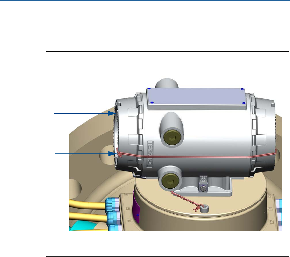
Daniel 3410 Series Ultrasonic Gas Flow Meter Installation Manual Section 3: Electrical installation
3-9000-759 Rev D June 2014
Seal Transmitter Electronics Enclosure 67
2. Install the security seal wire into and through one of the two holes in the end cap.
Choose holes that minimize counterclockwise rotation of the end cap when the
security wire is taut (maximum wire diameter .078 inch; 2.0mm).
Figure 3-11 Transmitter Electronics Enclosure security seals
3. Adjust the security wire, removing all slack and thread into the lead seal.
4. Crimp lead seal and cut wire ends to remove excess wire.
A.
A. Transmitter Electronics Enclosure end cap
B. Security wire seals
B.
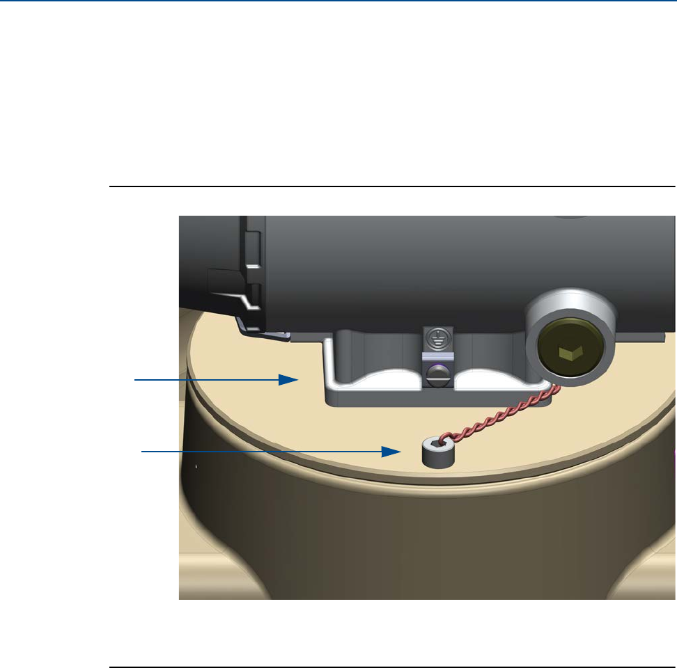
68 BASE ENCLOSURE SECURITY SEALS
Section 3: Electrical installation Daniel 3410 Series Ultrasonic Gas Flow Meter Installation Manual
June 2014 3-9000-759 Rev D
3.7.2 Base Enclosure Security Seals
Use the following instructions to install the security seal wire on the Base Enclosure.
Procedure
1. Install security wire seal into and through the hole in the socket head screw on the Base
Enclosure cover (maximum wire diameter .078 inch; 2.0mm).
Figure 3-12 Base Enclosure wire seal installation
2. Position the wire to prevent counterclockwise rotation of the screws when the seal wire
is taut.
A.
A. Base Enclosure cover
B.
B. Security wire seals

Daniel 3410 Series Ultrasonic Gas Flow Meter Installation Manual Section 3: Electrical installation
3-9000-759 Rev D June 2014
Base Enclosure Security Seals 69
3. Feed the security wire beneath the Transmitter Electronics Enclosure and through the
adjacent socket head screw. Twist the wire, removing all slack and seal.
Figure 3-13 Base Enclosure security seals
4. Cut wire ends to remove excess wire.
A.
A. Transmitter Electronics Enclosure
D.
B. Security wire sealse
C. Transmitter Electronics endcap security latch
B.
C.
D. Base Enclosure
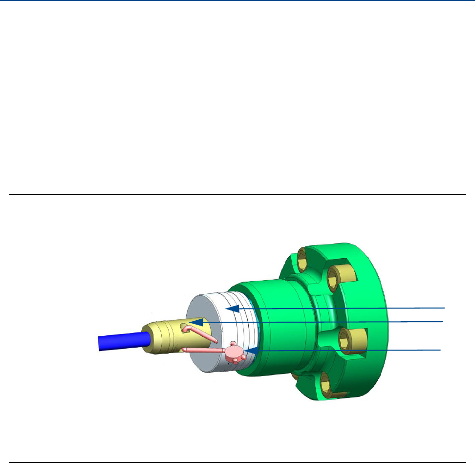
70 TRANSDUCER ASSEMBLY SECURITY SEALS
Section 3: Electrical installation Daniel 3410 Series Ultrasonic Gas Flow Meter Installation Manual
June 2014 3-9000-759 Rev D
3.7.3 Transducer assembly security seals
Use the following instructions and Figure 3-14 to install the security seal wire on the transducer
assembly.
1. Rotate the transducer cable nut (Item A) clockwise, compressing the seal on the
transducer cable connector.
2. Insert a security seal wire into one of the two holes in the transducer cable connector
(Item B) and feed through one of the two holes in the transducer cable nut (Item A).
Note: Choose holes that minimize counterclockwise rotation of the transducer cable
nut when the security wire (Item C) is taut.
3. Adjust the security wire, removing all slack and thread into the lead seal.
4. Cut wire ends to remove excess wire.
Figure 3-14 Transducer assembly security seal
A.
B.
C.
A. Transducer cable nut
B. Transducer cable connector
C. Security wire seal

Daniel 3410 Series Ultrasonic Gas Flow Meter Installation Manual Section 3: Electrical installation
3-9000-759 Rev D June 2014
Sealing the unit 71
3.7.4 Sealing the unit
The unit should be properly sealed with a sealing compound after electrical connections have
been tested according to the customer's Best Practices schedule. Some areas require a
witnessed Acceptance Test for the installed system and require that the meter run for a
predetermined length of time (approximately one to two weeks) before the unit is sealed. This
allows time to verify all electrical connections are correct, that the meter is accurately
measuring flow and that the meter meets the customer’s installation requirements.
See Section 3.4.1 and Section 3.4.2

72 SEALING THE UNIT
Section 3: Electrical installation Daniel 3410 Series Ultrasonic Gas Flow Meter Installation Manual
June 2014 3-9000-759 Rev D

Daniel 3410 Series Ultrasonic Gas Flow Meter Installation Manual Section 4: Configuration
3-9000-759 Rev D June 2014
Daniel MeterLink Setup 73
Section 4: Configuration
After the mechanical and electrical installation is complete and connectivity is established, use
the Daniel MeterLink Software for Gas and Liquid Ultrasonic Meters Quick Start Manual
(P/N 3-9000-763) to setup software communications with the meter.
4.1 Daniel MeterLink Setup
1. Review the software operating system, hardware and peripheral requirements.
2. Follow the installation instructions for your operating system (Windows® XP, Windows
Vista®, Windows® 7 or Windows® 8).
3. Configure a direct connection driver for first time modem configuration for Daniel
MeterLink communications.
4. Select the Daniel MeterLink desktop icon and complete the information in the
Registration Wizard to keep you informed about updates and technical support.
Registration options include:
•Register by e-mail
•Register by phone
•Register later (remind me)
•Register later using the Help|Resister Program menu (don’t remind me)
5. Select File|Program Settings and customize the user-preferences (e.g. User name,
Company name, display units, Liquid Meter volume units and other interface settings)
6. Connect to your meter. If your meter is not shown in the list, select Edit Meter Directory
and setup the connections properties.
7. Save the meter configuration file, collect a Maintenance log and Waveforms to
document the meter’s “As Found” settings.
8. Run the Field Setup Wizard.

74 Field Setup Wizard
Section 4: Configuration Daniel 3410 Series Ultrasonic Gas Flow Meter Installation Manual
June 2014 3-9000-759 Rev D
4.2 Field Setup Wizard
1. Use the Field Setup Wizard-Startup in Daniel MeterLink and select the checkboxes that
allow proper configuration for your meter (Temperature, Pressure, Meter Corrections,
Meter Outputs, Gas chromatograph setup, Continuous flow analysis, View local display
setup, 4+4 8-path meter combine output and SOS limit percentage). Selections on this
page will affect other configuration selections. Select Next to continue to General
setup.
2. Use General setup to configure the meter’s units system (U.S Customary or Metric
units) volume units, flow rate time, low flow cutoff, contract hour, enable reverse flow
alarm, set meter time and notepad comments. Select Next to continue to Frequency/
Digital Outputs page.
Note: The Meter’s Units system configured on the General Page affect the units for the
optional Local Display items.
3. Set the Frequency/Digital Outputs Sources for either a frequency output or a digital
status. Select the Source for each Frequency/Digital output and select the desired drive
Mode. The Mode options are Open Collector which requires an external excitation
voltage and pull-up resistor or TTL mode which outputs a 0-5 VDC signal. Select Next to
continue to Frequency Outputs page.
Note: Frequency outputs 1 and Digital outputs 1 are paired together meaning the
Digital outputs 1 will report the status for the parameter for Frequency outputs 1.
Similarly, Frequency outputs 2 and Digital outputs 2 are paired together. Additionally,
each Frequency output has an A and B output phase.
4. Configure Frequency output 1 and Frequency output 2 content, flow direction, Channel
B phase, maximum frequency output (Hertz) and full scale volumetric flow rate. Select
Next to continue to Meter Digital Outputs.
5. Select the Meter Digital Output parameters for Digital output 1A, Digital output 1B,
Digital output 2A and Digital output 2B based on Frequency validity or flow direction.
if the output of the ultrasonic meter is reversed from what a flow computer is
expecting, select Inverted Operation. This changes the digital output from a HIGH for a
TRUE condition to output a LOW for a TRUE condition. Select Next to continue to
Current Outputs.
6. Current Outputs are based on Uncorrected (Actual) flow rate) content, flow direction
(Forward, Reverse or Absolute) and Full scale volumetric flow rate used with output
(20mA maximum). Alarm action parameters determines the state the output will drive
during an alarm condition (High 20mA, Low - 4 mA, Hold last value, Very low - 3.5, Very
high 20.5 mA or None). Select Next to configure the HART® Output(s) parameters.
7. HART® Output parameters include four Dynamic process variables (Primary,
Secondary, Third and Fourth variable. The Primary variable is set to match the Content
set for Current output 1. If a second current output is available, the Secondary variable
is set to match the Content set for Current output 1) Identification and HART® units
(volume units, flow rate time units, velocity units, pressure and temperature units).
Select Next to continue to the Meter Corrections page.

Daniel 3410 Series Ultrasonic Gas Flow Meter Installation Manual Section 4: Configuration
3-9000-759 Rev D June 2014
Field Setup Wizard 75
8. The Meter Corrections page allows you to configure the flow profile, temperature,
pressure and linear expansion corrections, pipe outside diameter The Young’s Modulus
value (ratio of tensile stress to tensile strain) and the Poisson’s ratio value (the absolute
ratio of the pipe material lateral strain over axial strain) for 3412 and 3411 Gas
Ultrasonic Flow meters. Click Next to continue to the Temperature and Pressure page.
9. Set the temperature and pressure scaling for analog inputs, enter fixed values, and set
alarm limits for both. The alarm limit selections are hold last output value or use fixed
value.
•Live temperature selections include minimum and maximum inputs or fixed
temperature.
•Live pressure selections include minimum and maximum inputs, gage
(atmospheric pressure), absolute, or fixed pressure.
Click Next to continue to the Gas Chromatograph Setup page.
10. Select the settings below to configure a serial port as a Modbus Master to poll a gas
chromatograph.
•Serial Port: select which serial port will be connected to the GC. While the port is
configured for communications to a GC, it will not act as a Modbus slave device
for communications from Daniel MeterLink™ or a SCADA system.
•GC protocol: select the protocol for which the GC is configured. The Daniel Gas
Ultrasonic meter uses 7 data bits, Even parity, and 1 stop bit for ASCII Modbus
and 8 data bits, No parity, and 1 stop bit for RTU Modbus
•GC baud rate: select the baud rate for which the GC is configured.
•GC comms address: enter the Modbus ID of the GC.
•GC stream number: enter the stream number for the gas composition the Daniel
Gas Ultrasonic meter will read.
•GC heating value units: elect the units for which the heating value is configured
in the GC.
•Use which gas composition on GC alarm: select which gas composition the
Daniel Gas Ultrasonic meter will use if the GC goes into alarm. If Fixed value is
selected, the meter will start using the fixed gas composition stored in the meter.
If Last good value is selected, the meter will use the last gas composition
collected from the GC before the GC started to report alarms. Click Next to
continue to the AGA8 page.

76 Field Setup Wizard
Section 4: Configuration Daniel 3410 Series Ultrasonic Gas Flow Meter Installation Manual
June 2014 3-9000-759 Rev D
11. Configure the properties necessary for the AGA8 calculations. This page is only
displayed for Daniel Gas Ultrasonic meters if both temperature and pressure are set to
Live or Fixed and Base condition correction is selected on the Startup Page.
Configuration parameters include:
•Calculations performed internally (by the meter) or Externally
•AGA8 method - Gross Method 1, Gross method 2 or Detail
•Base temperature and pressure
•Specific gravity - reference temperature and pressure
•Volumetric gross heating value and reference temperature
•Molar density reference temperature and pressure
•Flow Mass density, flow compressibility and Base compressibility
•Gas composition inputs - components and mole percent
Click Next to continue to the Continuous Flow Analysis page, if View Continuous Flow
Analysis setup was selected on the Startup page.
12. Configure the flow analysis parameters shown below.
•Set low and high flow limits
•Enable SOS comparison (requires AGA 8 Detail method)
•Enable liquid detection and Profile factor limit
•Enable Blockage. Enter the percent for Symmetry, Cross-flow, Chords A to D
turbulence
•Enable Internal bore buildup
Click Next to continue to the Local display page, if View local display setup was selected
on the Startup page.
13. Configure the parameters for the local display. Use the drop-down arrow in the Display
Items list box and select or modify the parameters that will be displayed; the Display
items, the Display units and the Scroll delay.
Daniel 3410 Series Ultrasonic Gas Flow Meter Installation Manual Section 4: Configuration
3-9000-759 Rev D June 2014
Field Setup Wizard 77
Display Items:
The Local Display’s labels and descriptions are shown below:
Table 4-1 Local display labels, descriptions and valid units
Local display labels, descriptions and valid units
QFLOW — Uncorrected volume flow rate
•ACF – Actual Cubic Feet
•ACM – Actual Cubic Meters
•MACF – Thousand Actual Cubic Feet
•MACM –Thousand Actual Cubic Meters
TDYVL — Current day’s forward uncorrected volume
•+ACF – Actual Cubic Feet
•+ACM – Actual Cubic Meters
•+MACF – Thousand Actual Cubic Feet
•+MACM –Thousand Actual Cubic Meters
TDYVL — Current day’s reverse uncorrected volume
•-ACF – Actual Cubic Feet
•-ACM – Actual Cubic Meters
•-MACF – Thousand Actual Cubic Feet
•-MACM –Thousand Actual Cubic Meters
YSTVL — Previous day’s forward uncorrected volume
•+ACF – Actual Cubic Feet
•+ACM – Actual Cubic Meters
•+MACF – Thousand Actual Cubic Feet
•+MACM –Thousand Actual Cubic Meters
YSTVL — Previous day’s reverse uncorrected volume
•-ACF – Actual Cubic Feet
•-ACM – Actual Cubic Meters
•-MACF – Thousand Actual Cubic Feet
TOTVL — Forward uncorrected volume
•+ACF – Actual Cubic Feet
•+ACM – Actual Cubic Meters
•+MACF – Thousand Actual Cubic Feet
•+MACM –Thousand Actual Cubic Meters
TOTVL — Reverse uncorrected volume
•-ACF – Actual Cubic Feet
•-ACM – Actual Cubic Meters
•-MACF – Thousand Actual Cubic Feet
•-MACM –Thousand Actual Cubic Meters
QBASE — Corrected volume flow rate
•SCF – Standard Cubic Feet
•SCM – Standard Cubic Meters
•MSCF – Thousand Standard Cubic Feet
•MSCM – Thousand Standard Cubic Meters
78 Field Setup Wizard
Section 4: Configuration Daniel 3410 Series Ultrasonic Gas Flow Meter Installation Manual
June 2014 3-9000-759 Rev D
TDYVL — Current days forward corrected volume
•+SCF – Standard Cubic Feet
•+SCM – Standard Cubic Meters
•+MSCF – Thousand Standard Cubic Feet
•+MSCM – Thousand Standard Cubic Meters
TDYVL — Current days reverse corrected volume
•-SCF – Standard Cubic Feet
•-SCM – Standard Cubic Meters
•-MSCF – Thousand Standard Cubic Feet
•-MSCM – Thousand Standard Cubic Meters
YSTVL — Previous days forward corrected volume
•+SCF – Standard Cubic Feet
•+SCM – Standard Cubic Meters
•+MSCF – Thousand Standard Cubic Feet
•+MSCM – Thousand Standard Cubic Meters
YSTVL — Previous days reverse corrected volume
•-SCF – Standard Cubic Feet
•-SCM – Standard Cubic Meters
•-MSCF – Thousand Standard Cubic Feet
•-MSCM – Thousand Standard Cubic Meters
TOTVL — Forward corrected volume
•+SCF – Standard Cubic Feet
•+SCM – Standard Cubic Meters
•+MSCF – Thousand Standard Cubic Feet
•+MSCM – Thousand Standard Cubic Meters
TOTVL — Reverse corrected volume
•-SCF – Standard Cubic Feet
•-SCM – Standard Cubic Meters
•-MSCF – Thousand Standard Cubic Feet
•-MSCM – Thousand Standard Cubic Meters
VEL — Average flow velocity
•Ft/S – Feet per Second
•M/S – Meters per Second
SOS — Average sound velocity
•Ft/S – Feet per Second
•M/S – Meters per Second
TEMP — Flow-condition temperature
•DEGF – Degrees Fahrenheit
•DEGC – Degrees Celsius
PRESS — Flow-condition pressure
•PSI – Pound per square inch
•MPA – Megapascals
FRQ1A — Frequency channel 1A
•HZ – Hertz
FRQ1B — Frequency channel 1B
•HZ – Hertz
Table 4-1 Local display labels, descriptions and valid units
Local display labels, descriptions and valid units
Daniel 3410 Series Ultrasonic Gas Flow Meter Installation Manual Section 4: Configuration
3-9000-759 Rev D June 2014
Field Setup Wizard 79
Note: When connected to a meter with the local display option, reverse flow
direction is indicated with a minus sign (negative) before the value(s) shown on
the local display.
Display units:
The Meter volume units displayed are either U.S. Customary or Metric. To modify the Display
Units, configure the Meter units system in the Field Setup Wizard — General Page.
•U.S. Customary volume unit selections are:
–Cubic feet
–Thousand cubic feet
•Metric volume unit selections are:
–Cubic meters
•Display units preceded by a plus or minus sign indicate forward and reverse flow
direction, as shown in the table below.\
•The local display Flow rate time units are modifiable by selecting the drop-down arrow
and clicking the time unit in the list box.
•Valid flow rate time units selections are:
–second
–hour
–day
KFCT1 — Frequency 1 K-factor
•CF – Cubic Feet
•CM –Cubic Meters
•MCF – Thousand Cubic Feet
•MCM –Thousand Cubic Meters
FRQ2A — Frequency channel 2A
•HZ – Hertz
FRQ2B — Frequency channel 2B
•HZ – Hertz
KFCT2 — Frequency 2 K-factor
•CF – Cubic Feet
•CM –Cubic Meters
•MCF – Thousand Cubic Feet
•MCM –Thousand Cubic Meters
AO1 — Analog Output 1 current
•MA – Milliamperes
AO2 — Analog Output 2 current
•MA – Milliamperes
Table 4-1 Local display labels, descriptions and valid units
Local display labels, descriptions and valid units

80 Using AMS Device Manager to configure the meter
Section 4: Configuration Daniel 3410 Series Ultrasonic Gas Flow Meter Installation Manual
June 2014 3-9000-759 Rev D
Scroll delay:
The Scroll Delay is the time interval for the selected display items to be shown on the Local
Display. The default scroll delay setting is five seconds. Click the spin box up or down arrow to
increase or decrease the length of time an item displays.
1. Select Finish to write the configuration settings to the meter.
2. Save the meter configuration file, collect a Maintenance log and Waveforms to
document the “As Left” settings.
4.3 Using AMS Device Manager to configure the
meter
This procedure assumes you have AMS Device Manager installed on the host computer and have
downloaded the latest Daniel Liquid Ultrasonic Meter Device Description (DD).
If not installed, click the link below to download the AMS device installation tool kit.
http://www2.emersonprocess.com/en-US/documentation/deviceinstallkits/Pages/devicein-
stallkitsearch.aspx

Daniel 3410 Series Ultrasonic Gas Flow Meter Installation Manual Section 4: Configuration
3-9000-759 Rev D June 2014
Using AMS Device Manager to configure the meter 81
Procedure - installing AMS Device Description
1. Use the link above to search for the Device Description (DD) for your Daniel 3810 Series
Liquid Ultrasonic Flow Meter.
2. Use the pull-down menu and select the Brand/Manufacturer - Emerson Daniel Industries.
3. Next select the Device, Liquid 3810 Series from the pull-down menu.
4. Choose the Device Revision1, from the pull-down menu.
5. Next, select HART from the Communication Protocol menu.
6. Select AMS Device Manager for the Host System.
7. Select the Host System Revision 11.5.
8. Verify your search parameters are correct, as shown below.
Figure 4-1 AMS Device Description search
9. Click Search Now.

82 Using AMS Device Manager to configure the meter
Section 4: Configuration Daniel 3410 Series Ultrasonic Gas Flow Meter Installation Manual
June 2014 3-9000-759 Rev D
10. Click the Daniel Industries Liquid 3810 Series Rev 1 hyperlink. The file download dialog
displays. Click the Save button to save the files to your host system. You may use the
default download location or change the directory.
11. AMS file download options
12. Click the Save button to complete the file download.
Figure 4-2 AMS file download complete
13. Click Open or Open Folder to view the downloaded files.
14. Establish power to the meter and wiring to Analog Input 1 for HART communication.
15. Start the AMS Device Manager using a laptop or PC.
16. Enter login credentials and click OK to launch the application.
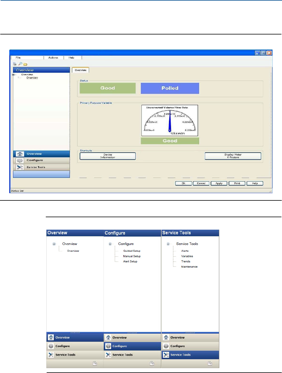
Daniel 3410 Series Ultrasonic Gas Flow Meter Installation Manual Section 4: Configuration
3-9000-759 Rev D June 2014
Using AMS Device Manager to configure the meter 83
17. Click the Configure tab, and then select Guided Setup, Manual Setup or Alert Setup.
Figure 4-3 AMS Device Manager
Figure 4-4 AMS Device Manager - Overview
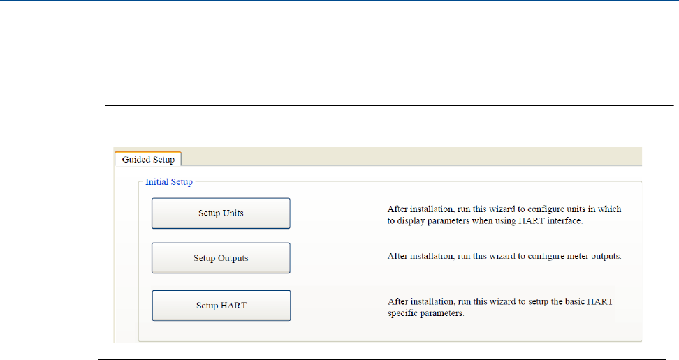
84 Using AMS Device Manager to configure the meter
Section 4: Configuration Daniel 3410 Series Ultrasonic Gas Flow Meter Installation Manual
June 2014 3-9000-759 Rev D
AMS Device Manager - Guided Setup
The Guided setup wizard provides configuration parameter settings for the meter. The Guided
Setup is a subset of the Manual Setup parameters.
Figure 4-5 AMS Device Manager - Guided Setup
Note: Before writing configuration changes to your meter, make sure you have saved
the Configuration file and Maintenance log.
Procedure
1. Disable the Write Protect switch in the CPU Module to write any of the following
configuration parameters to your meter.
2. Click the Setup Units tab to configure the system units (U.S. Customary or Metric units),
Volume units, Flow rate time units, Velocity units, Pressure units and Temperature
units. Click Apply to write the parameters to the meter.
3. Click the Setup Outputs tab to configure the Device Variables Mapping, Units,
Frequency/Digital outputs, Frequency and Digital Outputs 1 and 2, Analog outputs,
Digital Input, Pressure and Temperature.
a. Analog output 1 (HART) - Content (Primary Variable) displays Uncorrected Flow
Rate and is a read only attribute). Configure Direction (flow), Lower Range value,
Upper range value and Alarm Action and view the HART Parameters Tag, Date,
Descriptor, Message, Final Assembly Number Poll Address, Number of Response
Preambles.
b. Analog Output 2 - Content (Secondary Variable) displays Uncorrected Flow Rate
and has a read only attribute. Configure Direction (flow), Lower Range value,
Upper range value and Alarm Action. Map the Third and Four variables using the
Manual Setup wizard. Selections include Uncorrected Volume Flow Rate,
Pressure and Temperature.

Daniel 3410 Series Ultrasonic Gas Flow Meter Installation Manual Section 4: Configuration
3-9000-759 Rev D June 2014
Using AMS Device Manager to configure the meter 85
4. After all of the data shown below is entered, click Apply to write the parameters to the
meter.
a. Click the Frequency/Digital Outputs tab to configure Frequency/Digital Output 1,
2 and 3 Source and drive Mode. Select the Source for each Frequency/Digital
output and select the desired drive Mode. The Mode options are Open Collector
which requires an external excitation voltage and pull-up resistor or TTL mode
which outputs a 0-5 VDC signal (each Frequency output has an A and B output
phase). (Refresh Note: If changes are made to any Source variable on this page,
apply the changes and navigate to the Guided Setup page. Navigate back to the
Manual Setup for the changes to be reflected in other Manual Setup pages).
b. Click the Frequency and Digital Output 1 tab to configure the Content, (flow)
Direction, Channel B Phase frequency output, Lag forward, Lead Reverse or Lead
Forward, Lag Reverse (Phase B lags Phase A while reporting forward flow and lead
Phase A while reporting reverse flow or the opposite), Digital Output 1 Channel A
Content and Polarity, Channel B Content and Polarity, Maximum Frequency, and
Lower and Upper Range Units of Measure.
c. Click the Frequency and Digital Output 2 tab and repeat Step 3b to configure
Frequency and Digital Output 2 parameters.
5. Click Setup HART to configure the HART parameters (tag, date, descriptor, message
text, Final Assembly number, Poll address and number of response preambles are
displayed). After all of the data is entered click Apply to write the parameters to the
meter.
6. On the Overview page, click Alert Setup and select the Flow Analysis tab and enable
Reverse Flow. Click the OK button to return to the Overview page.
7. On the Overview page, click the Service Tools tab and select the Variables tab. The Flow
Data, Path Information, Flow Totals, and All Variables data is populated after you are
connected to the meter.
a. Click the Flow Data tab and view the Flow Direction (Forward or Reverse),
Average Flow and Average Sound Velocities values.
b. Click the Path Information tab and view the Chord performance, Gain, SNR (Signal
to Noise Ratio) Signal strength (mV), and Noise (mV).
c. Click the Flow Totals tab to view the volume totals (forward and reverse
uncorrected volume).
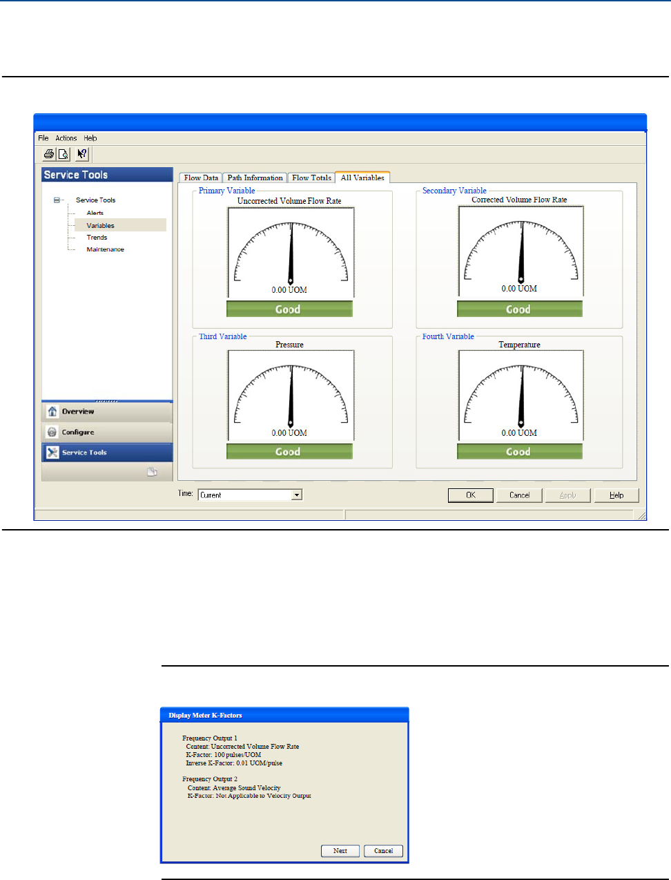
86 Using AMS Device Manager to configure the meter
Section 4: Configuration Daniel 3410 Series Ultrasonic Gas Flow Meter Installation Manual
June 2014 3-9000-759 Rev D
d. Click the All Variables tab to view a graphical display of the Primary, Secondary,
Third and Fourth Variables.
Figure 4-6 AMS Device Manager - Service Tools All Variables status indicators
8. Click OK to return to the Overview page.
9. Enable the Write Protect switch on the CPU Module to protect the meter’s
configuration.
10. From the Overview window, click Display Meter K-Factors. K-Factors are a read-only
values calculated from the Full scale volumetric flow rate used with frequency outputs
and the Maximum frequency for frequency output.
Figure 4-7 Display Meter K-Factors
Click Next to return to the Device Manager Overview page.
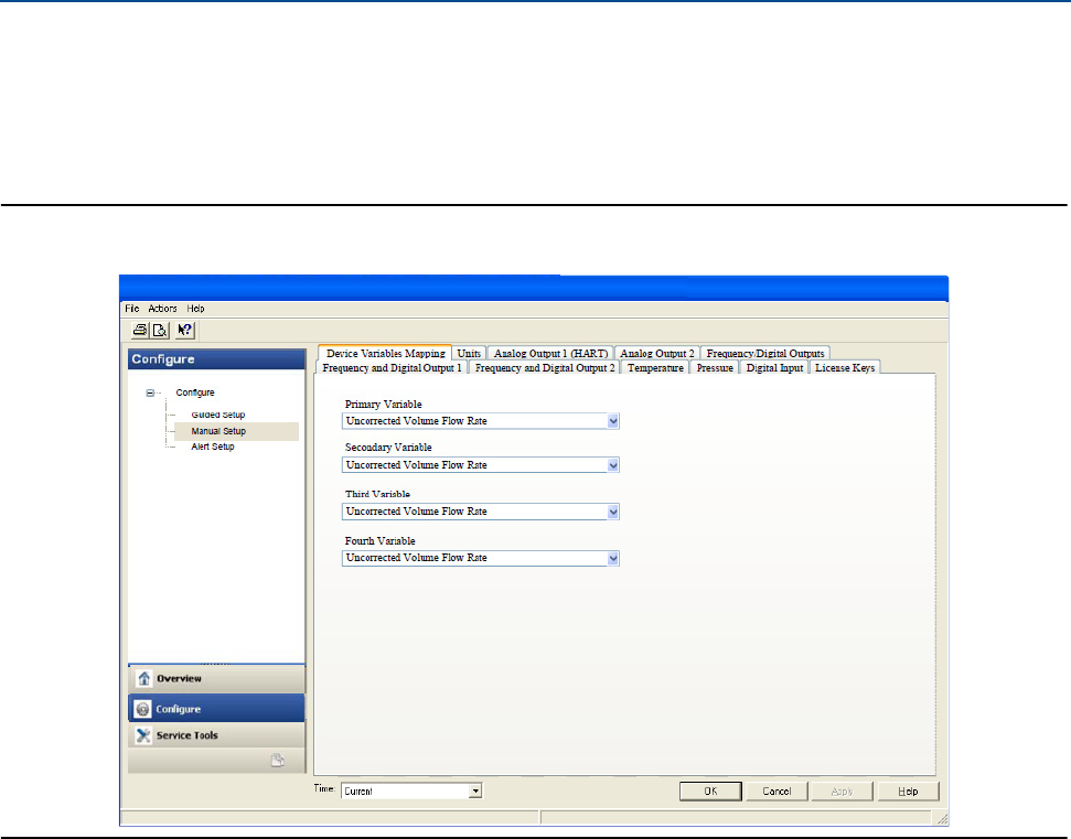
Daniel 3410 Series Ultrasonic Gas Flow Meter Installation Manual Section 4: Configuration
3-9000-759 Rev D June 2014
Using AMS Device Manager to configure the meter 87
AMS Device Manager - Manual Setup
Use the Manual Setup wizard to configure the meter’s parameters. See Figure 4-3 and Figure 4-4
and from the AMS Device Manager Configure menu click Manual Setup.
Figure 4-8 AMS Device Manager - Configure Manual Setup
Procedure
1. If installed, remove security wires from the endcap and the Bracket/Cover hex head
bolts that secures the Base Enclosure.
1. Disable the Write Protect switch in the CPU Module to write any of the following
configuration parameters to your meter.
2. Click the Device Variables Mapping tab. The Primary and Secondary variables are read
only and are configured for Uncorrected Flow Rate. The Third and Fourth variable
configuration choices include Pressure and Temperature.
3. Click the Units tab (see AMS Device Manager - Guided Setup, Step 2).
4. Click the Analog Output 1 (HART) tab (see AMS Device Manager - Guided Setup, Step 3).
5. Click the Analog Output 2 tab. Follow the configuration instructions in the AMS Device
Manager - Guided Setup, Step 3. The read only Secondary variable Content,
Uncorrected Flow Rate, displays. Use the drop-down arrow and select the (flow)
Direction - Forward or Reverse. Enter a Lower and Upper Range limit. Set the Alarm
Action parameters. Click Apply, after you enter the data to write the parameters to the
meter.

88 Using AMS Device Manager to configure the meter
Section 4: Configuration Daniel 3410 Series Ultrasonic Gas Flow Meter Installation Manual
June 2014 3-9000-759 Rev D
6. Click the Frequency/Digital Outputs tab. Follow the configuration instructions in the
AMS Device Manager - Guided Setup, Step 4a.). (Refresh Note: If changes are made to
any Source variable on this page, apply the changes and navigate to the Guided Setup
page. Navigate back to the Manual Setup for the changes to be reflected in other
Manual Setup pages). Click Apply, after you enter the data to write the parameters to
the meter.
7. Click the Frequency and Digital Output 1 tab. Follow the configuration instructions in the
AMS Device Manager - Guided Setup, Step 4b. Click Apply, after you enter the data to
write the parameters to the meter.
8. Click the Frequency and Digital Output 2 tab. Follow the instructions in the AMS Device
Manager - Guided Setup, Step 4c to configure the Frequency and Digital Output 2
parameters. Click Apply, after you enter the data to write the parameters to the meter.
9. Click the Temperature tab. Configure the input parameters including: Source (Live
Analog or Fixed), Min and Max input limits corresponding to 4 mA and 20 mA
respectively and the Low and High alarm limits. Click Apply, after you enter the data to
write the parameters to the meter.
10. Click the Pressure tab. Configure the input parameters including: Source (Live Analog or
Fixed), Min and Max input limits corresponding to 4 mA and 20 mA respectively and the
Low and High alarm limits. Select either Gage or Absolute for the type of pressure
reading desired. If a live pressure transmitter is connected, select the type of reading
the transmitter outputs. If Absolute is selected, you must also enter the Atmospheric
pressure. Click Apply, after you enter the data to write the parameters to the meter.
11. Click the Digital Input tab. The default Digital Input 1 polarity is set to Normal for general
purpose or set to Inverted when used for calibration. Click Apply, after you choose the
calibration data to write the parameters to the meter.
a. Calibration Polarity configuration parameter selections are:
–Digital Input 1 Calibrate Active High
–Digital Input 1 Calibrate Active Low
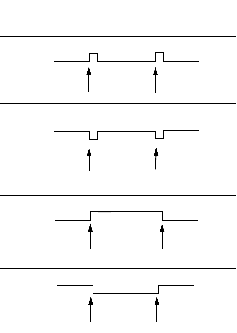
Daniel 3410 Series Ultrasonic Gas Flow Meter Installation Manual Section 4: Configuration
3-9000-759 Rev D June 2014
Using AMS Device Manager to configure the meter 89
b. Calibration Gating configuration parameter selections are:
–Edge gated, active high
Figure 4-9 Gating configuration parameter Edge gated, active high
–Edge gated, active low
Figure 4-10 Gating configuration parameter Edge gated, active low
–State gated, active high
Figure 4-11 Gating configuration parameter State gated, active high
–State gated, active low
Figure 4-12 Gating configuration parameter State gated, active low
High
Low
Calibration Start Calibration Stop
High
Low
Calibration Start Calibration Stop
High
Low
Calibration Start Calibration Stop
High
Low
Calibration Start Calibration Stop
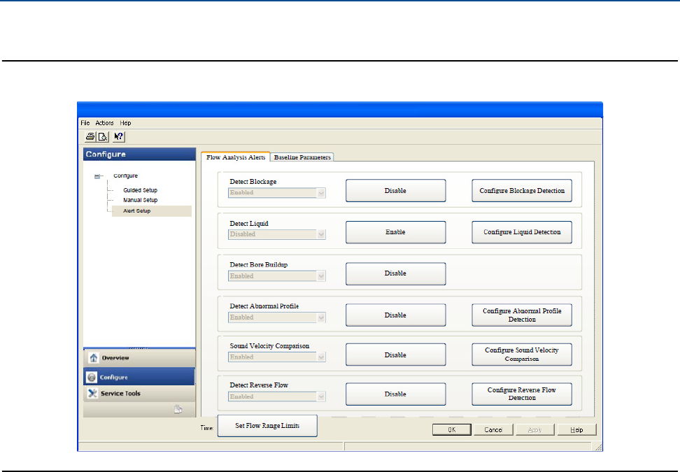
90 Using AMS Device Manager to configure the meter
Section 4: Configuration Daniel 3410 Series Ultrasonic Gas Flow Meter Installation Manual
June 2014 3-9000-759 Rev D
12. Click the Alert Setup tab (from the main Configuration page).
Figure 4-13 Configure Flow Analysis Alert
13. Click the Flow Analysis tab to select Configure Reverse Flow Detection, if desired. The
default setting is Disabled. Click the Disabled button to send the feature command to
the meter. Check for a response error. If no error response is received, click the Enable
button.
a. Enter the minimum reverse flow velocity above which to accumulate flow in the
reverse direction for this alert. Enter a positive value for the Reverse Flow Zero
Cutoff. Click the Next button to write the values to the meter. Check for an error
response. If no error response is received, click the Next button. The Detect
Reverse Flow enabled page displays. Click the Next button to display Detect
Reverse Flow disabled.
b. If an error message is returned, click the Next button to display the Method
Complete page.
c. Click the Set Flow Range Limits button and enter a positive value for the Flow
Analysis Lower Velocity Range and the Upper Velocity Range Limits. When the
velocity is outside of the limit parameters, an alert is triggered. Click the Next
button to display the Method Complete page.
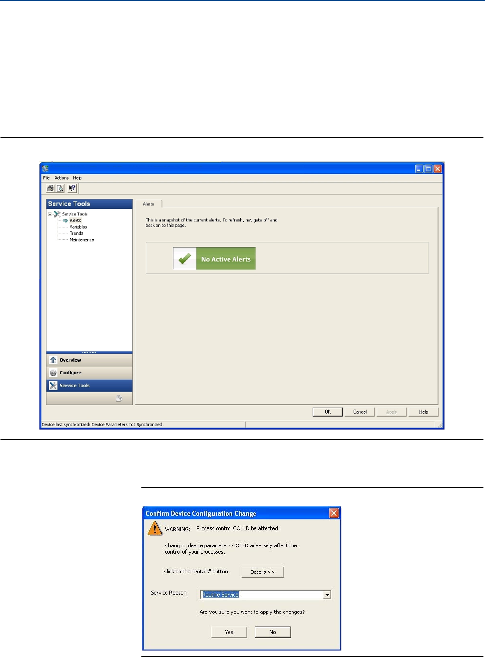
Daniel 3410 Series Ultrasonic Gas Flow Meter Installation Manual Section 4: Configuration
3-9000-759 Rev D June 2014
Using AMS Device Manager to configure the meter 91
14. Click the Service Tools tab to access the device alerts, variables, trends and maintenance
statuses or to edit the configuration parameters.
a. Click the Service Tools|Alerts tab. If an alert condition exists, the alert type and
description displays. Recommended actions are listed to assist you in a
resolution. After you resolve the alert condition, click the Acknowledge button to
clear the alert. Click Apply to write the changes to the meter. If no alert condition
is active, click OK to close the device window.
Figure 4-14 AMS Device Manager - Service Tools Alerts
b. If you change the device configuration, a confirmation dialog displays and
prompts you to write the changes to the meter. Click Yes to write the changes to
the meter or click No to cancel pending changes.
Figure 4-15 Configuration changes dialog

92 Using AMS Device Manager to configure the meter
Section 4: Configuration Daniel 3410 Series Ultrasonic Gas Flow Meter Installation Manual
June 2014 3-9000-759 Rev D
c. Click the Service Tools|Variables tab. The Variables page displays tabs for the
device’s Flow Data, Path Information, Flow Totals, and All Variables).
Figure 4-16 AMS Device Manager - Service Tools
d. The Service Tools|Flow Data page includes charts for flow and sound velocities.
The flow values (flow direction, average flow velocity and average sound
velocity) parameters are displayed for the connected device.
e. Click Service Tools|Variables|Path Information tab to view the device’s chord
performance (%), Gain (dB), SNR (dB), Signal (mV) and Noise (mV).
f. Click Service Tools|Variables|Flow Totals to view the volume totals (Forward and
reverse Uncorrected Volume) parameters for the connected device.
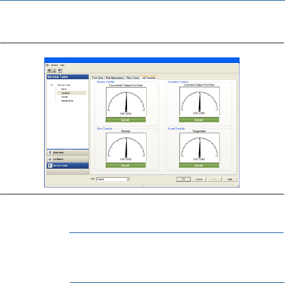
Daniel 3410 Series Ultrasonic Gas Flow Meter Installation Manual Section 4: Configuration
3-9000-759 Rev D June 2014
Using AMS Device Manager to configure the meter 93
g. Click Service Tools|Variables|All Variables tab to view Primary, Secondary, Third
and Fourth Variable parameter status.
Figure 4-17 AMS Device Manager - Service Tools All Variables
Gauges display each variable’s status as good or bad. If a status is bad refer to the
Service Tools Alerts page for recommended actions to resolve the alert condition. Also
refer to the Field Device Specification manual (P/N 3-9000-762) for Commands 48 and
140 details.
Alerts are triggered for Command 48 Additional device status and Command 140
detailed status information. Alerts are grouped as Failed - Fix Now, Maintenance - Fix
Soon and Advisory according to the severity level; 1-6. Severity 1 is the highest and 6 is
the lowest level.
IMPORTANT
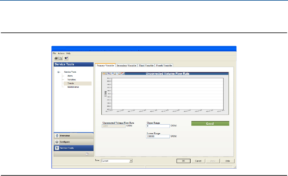
94 Using AMS Device Manager to configure the meter
Section 4: Configuration Daniel 3410 Series Ultrasonic Gas Flow Meter Installation Manual
June 2014 3-9000-759 Rev D
h. Click the Service Tools|Trends tab to display the device variables (uncorrected
volume flow rate, pressure and temperature) trends.
Figure 4-18 AMS Device Manager - Service Tools Trends
Primary and Secondary variables display real-time uncorrected volume flow rate
trends. The third and fourth variables charts displays trends for temperature and
pressure.
15. Click the Service Tools|Routine Maintenance tab. Click Analog Output 1 Trim to perform a
digital to analog trim adjustment of the first milliampere output. The 4mA and 20mA
output current values should equal the plant’s standard values. Click Yes to confirm the
configuration changes. Repeat this step to trim Analog Output 2 current. Click Apply to
write the output trim values to the meter. Click OK to navigate back to the Service Tools
page.
16. After you have changed and written the configuration changes to the meter do the
following:
a. Enable the Write Protect switch on the CPU Module to protect the meter’s
configuration.
b. Replace the end cap and if required, apply security seals through the endcap holes
and through the hex head bolts that secure the Bracket/Cover to the Base
enclosure.
Note: The next time you connect to the device using Daniel MeterLink, the Monitor
page displays a Meter status alarm that the configuration has changed and remains
latched until acknowledged. Click the Ack (acknowledge) button to clear the alarm.

Daniel 3410 Series Ultrasonic Gas Flow Meter Installation Manual Section 4: Configuration
3-9000-759 Rev D June 2014
Using a Field Communicator to configure the meter 95
4.4 Using a Field Communicator to configure the
meter
Installation Requirements
•Emerson Field Communicator software, license, installation guide and user manual
available on the Emerson Asset Optimization Field Communicator website:
http://www2.emersonprocess.com/en-US/brands/Field-Communicator/Pages/Documenta-
tion.aspx
•Daniel HART Device Description (HART DD) installed for the meter
•Network configured for a Field Communicator
•Daniel Field Device Specification Manual (P/N 3-9000-762) available on the Daniel website
http://www2.emersonprocess.com/en-US/brands/daniel/Flow/ultrasonics/Pages/Ultra-
sonic.aspx
•System wiring diagram drawing number DMC-005324 (see Appendix A)
•Power supply
Follow all guidelines and precautions described in the Field Communicator User Manual and in
the 3818 LNG Liquid Ultrasonic Flow Meter documentation when working in a hazardous area.
important

96 Using a Field Communicator to configure the meter
Section 4: Configuration Daniel 3410 Series Ultrasonic Gas Flow Meter Installation Manual
June 2014 3-9000-759 Rev D
Procedure
1. Remove electrical power to the meter. If installed, remove the endcap security latches
and seals and then, remove the endcap.
2. Refer to the Field Communicator Users Manual wiring diagrams and commissioning
instructions provided with your handheld device. Register the product to activate the
end user license.
3. Fully charge the Field Communicator battery prior to use. Important: Do not change
the battery in a hazardous area environment. The power supply is not intrinsically safe
4. On the meter, run the wires through the field wiring conduit and into the transmitter
electronics enclosure.
Figure 4-19 3414 transmitter field wiring conduit entries
A. Field wiring conduit entries (4)
A.

Daniel 3410 Series Ultrasonic Gas Flow Meter Installation Manual Section 4: Configuration
3-9000-759 Rev D June 2014
Using a Field Communicator to configure the meter 97
5. Wire Analog Input 1 (AI1) and Analog Output 1 (AO1) as shown in Figure 4-20 and
Appendix A, drawing DMC-005324.
Figure 4-20 Field Communicator wiring diagram for the 3410 Series electronics
6. Use the leads provided with the Field Communicator to connect to your device.
7. Press and hold the Power button on the Field Communicator until the green light blinks.
8. Use the touch screen on the Field Communicator, the keypad or use the stylus to
navigate through the device menus.
9. Refer to the Menu tree in Section D.1.1 of the Daniel HART Field Device Specification
manual (P/N 3-9000-762) for the device fast key sequences. Included in the menu tree
are:
•Diagram Page 1 - 3410 Series Root Menu; Overview, Configure>Manual Setup
•Diagram Page 2 - Configure|Manual Setup (continued) and Alerts Setup
•Diagram Page 3 - Service Tools|Alerts and Variables
•Diagram Page 4 - Service Tools|Variables (continued), Service Tools|Trends, and
Service Tools|Maintenance
10. If you encounter problems, refer to the contact information on the back cover of this
manual or the contacts included in the Field Communicator User’s Manual.

98 Security seals for the meter (optional)
Section 4: Configuration Daniel 3410 Series Ultrasonic Gas Flow Meter Installation Manual
June 2014 3-9000-759 Rev D
4.5 Security seals for the meter (optional)
For the integrity of the meter metrology and to prevent tampering with the transmitter
electronics and transducer assemblies, attach security latches on the end caps and install
security wires on the Transmitter Electronics Enclosure end caps, the Bracket/Cover cap head
screws. See Section 3.7 and Section 3.7.4.
Seal the conduit ports with sealing compound according to the customer’s requirements (e.g.,
after approximately one to two weeks of run time). Also, see Section 3.4.1.

Daniel 3410 Series Ultrasonic Gas Flow Meter Installation Manual Engineering drawings
3-9000-759 Rev D June 2014
3410 Series engineering drawings 99
APPENDIX APAGE 498
Appendix A: Engineering drawings
A.1 3410 Series engineering drawings
List of Engineering Drawings
This appendix contains the following engineering drawing(s) for the ultrasonic meter:
DMC-005324 Daniel 3410 Series Ultrasonic Gas Flow Meter System Wiring Diagram

100 3410 Series engineering drawings
Engineering drawings Daniel 3410 Series Ultrasonic Gas Flow Meter Installation Manual
June 2014 3-9000-759 Rev D
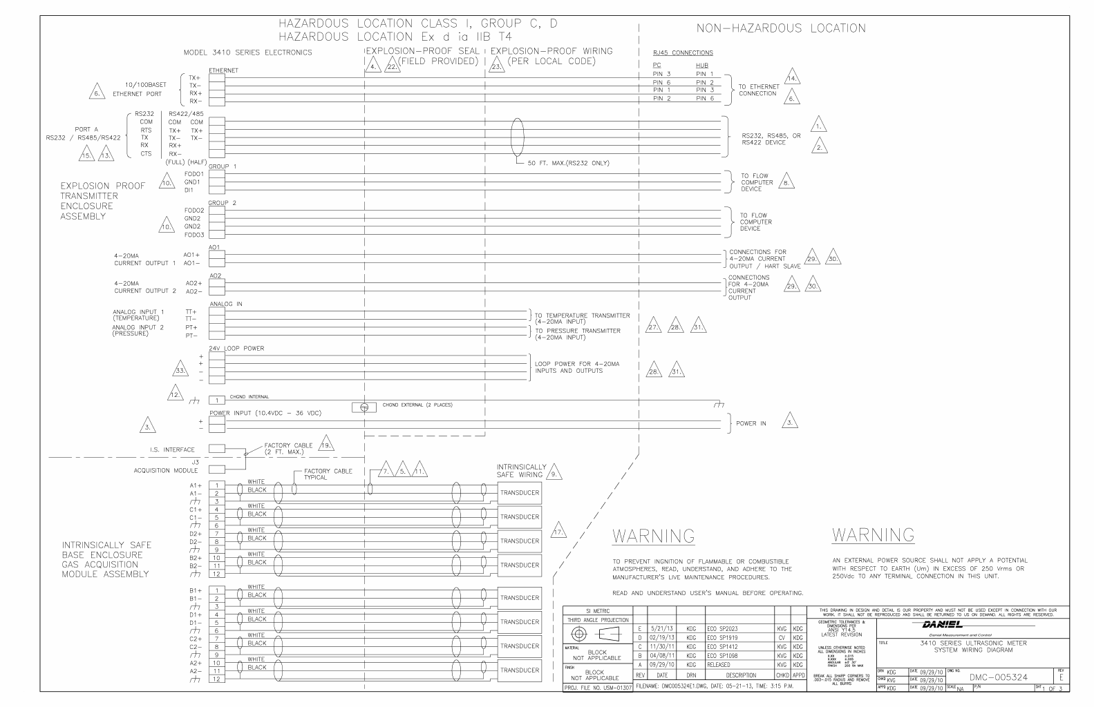
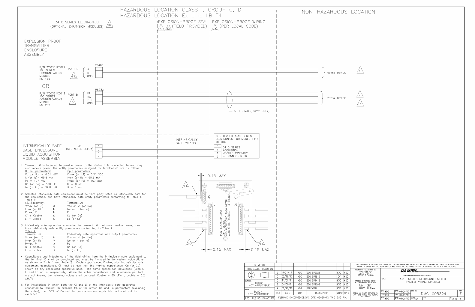
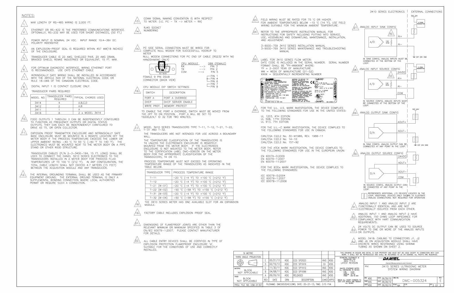

Daniel 3410 Series Ultrasonic Gas Flow Meter Installation Manual Open source licenses
3-9000-759 Rev D June 2014
101
A
Appendix B: Open source licenses
Source code for executable files or libraries included in this product is provided per the indicated
license in the table below. Hyperlinks to the controlling organization's websites are included in
Section B.1 through Section B.4.
Table B-1 Open source licences
Package File specification License Summary
base_libs-1.2-1 base_libs LGPL Base Libraries (from toolchain)
busybox-1.1.3-1 busybox GPL A small executable that replaces
many UNIX utilities
dev-1.1-1 dev GPL Device files for a small embedded
system
devmem2-1.0-1 devmem2 GPL Simple program to read/write
from/to any location
ethtool-3-1 ethtool GPL Ethernet settings tool for PCI
Ethernet cards
expat-2.0.1-1 expat MIT XML 1.0 parser
fake-provides-1.0-5 fake-provides GPL Fake provides to satisfy package
dependencies
gdb-6.6cs-1 gdb GPL Gdb - GNU Source level debugger
for C, C++
kernel-2.6.37-6 kernel-2.6.37-
mpc8313erd
GPL Linux kernel (core of the Linux
operating system)
libpcap-0.8.3-1 libpcap BSD A system-independent interface for
user-level pa
libtermcap-2.0.8-31_1 libtermcap LGPL A basic system library for accessing
the termcap
lwIP BSD A lightweight TCP/IP stack
merge-0.1-1 merge GPL Merge files for an embedded root
filesystem
modeps-1.0-1 modeps GPL Generate module dependency file
mtd-utils-20060302-1 mtd-utils GPL Memory Technology Device tools
net-tools-1.60-1 net-tools GPL Basic networking tools
ppp-2.4.4-1 ppp BSD Like a Point-to-Point Protocol
daemon
skell-1.16-2 skell GPL Skelleton files for an embedded
root filesystem
sqlite-3.6.22-1 sqlite Public domain SQLite is a C library that imple-
ments an embeddable SQL
database
102 GNU General Public License
Open source licenses Daniel 3410 Series Ultrasonic Gas Flow Meter Installation Manual
June 2014 3-9000-759 Rev D
Follow the link below to the Daniel® Liquid Ultrasonic Products GPL webpage for additional
open source information and zipped source code files.
http://www2.emersonprocess.com/en-US/brands/daniel/Pages/GPL3410.aspx
B.1 GNU General Public License
For more details about GNU GPL (General Public License), follow the link below:
http://www.gnu.org/
Daniel® Measurement and Control, Inc., uses GPL version 2.
http://www.gnu.org/licenses/old-licenses/gpl-2.0.html
The GNU GPL is currently version 3
http://www.gnu.org/licenses/quick-guide-gplv3.html
For older versions of the GNU General Public License, follow the link below:
http://www.gnu.org/licenses/old-licenses/old-licenses.html#GPL
See GPL license on the following pages.
strace-4.5.14-1 strace BSD trace system calls associated with a
running pro
sysconfig-1.2-1 sysconfig GPL System configuration package
sysfsutils-2.1.0-1 sysfsutils GPL/LGPL sysfs utilities
tcpdump-3.8.3-1 tcpdump BSD A network traffic monitoring tool
termcap-1.2-1 termcap BSD minimal /etc/termcap needed by
minicom etc
u-boot-1.3.0-1 u-boot-1.3.0-
mpc8313erdb
GPL Universal Bootloader firmware
ubi-utils-1.4.2-1 ubi-utils GPL Tools for maintaining Unsorted
Block Image Device
vsftpd-2.2.2-1 vsftpd GPL vsftpd - Very Secure Ftp Daemon
zlib-1.2.3-2 zlib zlib Distribution zlib compression
utilities and libraries
Package File specification License Summary

Daniel 3410 Series Ultrasonic Gas Flow Meter Installation Manual Open source licenses
3-9000-759 Rev D June 2014
GNU General Public License 103
The GNU General Public License (GPL)
Version 2, June 1991
Copyright (C) 1989, 1991 Free Software Foundation, Inc.
59 Temple Place, Suite 330, Boston, MA 02111-1307 USA
Everyone is permitted to copy and distribute verbatim copies
of this license document, but changing it is not allowed.
Preamble
The licenses for most software are designed to take away your freedom to share and change it. By
contrast, the GNU General Public License is intended to guarantee your freedom to share and change
free software--to make sure the software is free for all its users. This General Public License applies to
most of the Free Software Foundation's software and to any other program whose authors commit to
using it. (Some other Free Software Foundation software is covered by the GNU Library General Public
License instead.) You can apply it to your programs, too.
When we speak of free software, we are referring to freedom, not price. Our General Public Licenses
are designed to make sure that you have the freedom to distribute copies of free software (and
charge for this service if you wish), that you receive source code or can get it if you want it, that you
can change the software or use pieces of it in new free programs; and that you know you can do
these things.
To protect your rights, we need to make restrictions that forbid anyone to deny you these rights or to
ask you to surrender the rights. These restrictions translate to certain responsibilities for you if you
distribute copies of the software, or if you modify it.

104 GNU General Public License
Open source licenses Daniel 3410 Series Ultrasonic Gas Flow Meter Installation Manual
June 2014 3-9000-759 Rev D
For example, if you distribute copies of such a program, whether gratis or for a fee, you must give the
recipients all the rights that you have. You must make sure that they, too, receive or can get the
source code. And you must show them these terms so they know their rights.
We protect your rights with two steps: (1) copyright the software, and (2) offer you this license which
gives you legal permission to copy, distribute and/or modify the software.
Also, for each author's protection and ours, we want to make certain that everyone understands that
there is no warranty for this free software. If the software is modified by someone else and passed
on, we want its recipients to know that what they have is not the original, so that any problems
introduced by others will not reflect on the original authors' reputations.
Finally, any free program is threatened constantly by software patents. We wish to avoid the danger
that redistributors of a free program will individually obtain patent licenses, in effect making the
program proprietary. To prevent this, we have made it clear that any patent must be licensed for
everyone's free use or not licensed at all.
The precise terms and conditions for copying, distribution and modification follow.

Daniel 3410 Series Ultrasonic Gas Flow Meter Installation Manual Open source licenses
3-9000-759 Rev D June 2014
GNU General Public License 105
TERMS AND CONDITIONS FOR COPYING, DISTRIBUTION AND MODIFICATION
0. This License applies to any program or other work which contains a notice placed by the copyright
holder saying it may be distributed under the terms of this General Public License. The "Program",
below, refers to any such program or work, and a "work based on the Program" means either the
Program or any derivative work under copyright law: that is to say, a work containing the Program or
a portion of it, either verbatim or with modifications and/or translated into another language.
(Hereinafter, translation is included without limitation in the term "modification".) Each licensee is
addressed as "you".
Activities other than copying, distribution and modification are not covered by this License; they are
outside its scope. The act of running the Program is not restricted, and the output from the Program
is covered only if its contents constitute a work based on the Program (independent of having been
made by running the Program). Whether that is true depends on what the Program does.
1. You may copy and distribute verbatim copies of the Program's source code as you receive it, in any
medium, provided that you conspicuously and appropriately publish on each copy an appropriate
copyright notice and disclaimer of warranty; keep intact all the notices that refer to this License and
to the absence of any warranty; and give any other recipients of the Program a copy of this License
along with the Program.
You may charge a fee for the physical act of transferring a copy, and you may at your option offer
warranty protection in exchange for a fee.

106 GNU General Public License
Open source licenses Daniel 3410 Series Ultrasonic Gas Flow Meter Installation Manual
June 2014 3-9000-759 Rev D
2. You may modify your copy or copies of the Program or any portion of it, thus forming a work based
on the Program, and copy and distribute such modifications or work under the terms of Section 1
above, provided that you also meet all of these conditions:
a) You must cause the modified files to carry prominent notices stating that you changed the
files and the date of any change.
b) You must cause any work that you distribute or publish, that in whole or in part contains or
is derived from the Program or any part thereof, to be licensed as a whole at no charge to
all third parties under the terms of this License.
c) If the modified program normally reads commands interactively when run, you must cause
it, when started running for such interactive use in the most ordinary way, to print or
display an announcement including an appropriate copyright notice and a notice that there
is no warranty (or else, saying that you provide a warranty) and that users may
redistribute the program under these conditions, and telling the user how to view a copy
of this License. (Exception: if the Program itself is interactive but does not normally print
such an announcement, your work based on the Program is not required to print an
announcement.)
These requirements apply to the modified work as a whole. If identifiable sections of that work are not
derived from the Program, and can be reasonably considered independent and separate works in
themselves, then this License, and its terms, do not apply to those sections when you distribute them
as separate works. But when you distribute the same sections as part of a whole which is a work
based on the Program, the distribution of the whole must be on the terms of this License, whose
permissions for other licensees extend to the entire whole, and thus to each and every part regardless
of who wrote it.
Thus, it is not the intent of this section to claim rights or contest your rights to work written entirely
by you; rather, the intent is to exercise the right to control the distribution of derivative or collective
works based on the Program.

Daniel 3410 Series Ultrasonic Gas Flow Meter Installation Manual Open source licenses
3-9000-759 Rev D June 2014
GNU General Public License 107
In addition, mere aggregation of another work not based on the Program with the Program (or with a
work based on the Program) on a volume of a storage or distribution medium does not bring the other
work under the scope of this License.
3. You may copy and distribute the Program (or a work based on it, under Section 2) in object code or
executable form under the terms of Sections 1 and 2 above provided that you also do one of the
following:
a) Accompany it with the complete corresponding machine-readable source code, which must
be distributed under the terms of Sections 1 and 2 above on a medium customarily used
for software interchange; or,
b) Accompany it with a written offer, valid for at least three years, to give any third party, for
a charge no more than your cost of physically performing source distribution, a complete
machine-readable copy of the corresponding source code, to be distributed under the
terms of Sections 1 and 2 above on a medium customarily used for software interchange;
or,
c) Accompany it with the information you received as to the offer to distribute corresponding
source code. (This alternative is allowed only for noncommercial distribution and only if
you received the program in object code or executable form with such an offer, in accord
with Subsection b above.)
The source code for a work means the preferred form of the work for making modifications to it. For
an executable work, complete source code means all the source code for all modules it contains, plus
any associated interface definition files, plus the scripts used to control compilation and installation of
the executable. However, as a special exception, the source code distributed need not include
anything that is normally distributed (in either source or binary form) with the major components
(compiler, kernel, and so on) of the operating system on which the executable runs, unless that
component itself accompanies the executable.

108 GNU General Public License
Open source licenses Daniel 3410 Series Ultrasonic Gas Flow Meter Installation Manual
June 2014 3-9000-759 Rev D
If distribution of executable or object code is made by offering access to copy from a designated
place, then offering equivalent access to copy the source code from the same place counts as
distribution of the source code, even though third parties are not compelled to copy the source along
with the object code.
4. You may not copy, modify, sublicense, or distribute the Program except as expressly provided
under this License. Any attempt otherwise to copy, modify, sublicense or distribute the Program is
void, and will automatically terminate your rights under this License. However, parties who have
received copies, or rights, from you under this License will not have their licenses terminated so long
as such parties remain in full compliance.
5. You are not required to accept this License, since you have not signed it. However, nothing else
grants you permission to modify or distribute the Program or its derivative works. These actions are
prohibited by law if you do not accept this License. Therefore, by modifying or distributing the
Program (or any work based on the Program), you indicate your acceptance of this License to do so,
and all its terms and conditions for copying, distributing or modifying the Program or works based on
it.
6. Each time you redistribute the Program (or any work based on the Program), the recipient
automatically receives a license from the original licensor to copy, distribute or modify the Program
subject to these terms and conditions. You may not impose any further restrictions on the recipients'
exercise of the rights granted herein. You are not responsible for enforcing compliance by third
parties to this License.
7. If, as a consequence of a court judgment or allegation of patent infringement or for any other
reason (not limited to patent issues), conditions are imposed on you (whether by court order,
agreement or otherwise) that contradict the conditions of this License, they do not excuse you from
the conditions of this License. If you cannot distribute so as to satisfy simultaneously your obligations
under this License and any other pertinent obligations, then as a consequence you may not distribute
the Program at all. For example, if a patent license would not permit royalty-free redistribution of the

Daniel 3410 Series Ultrasonic Gas Flow Meter Installation Manual Open source licenses
3-9000-759 Rev D June 2014
GNU General Public License 109
Program by all those who receive copies directly or indirectly through you, then the only way you
could satisfy both it and this License would be to refrain entirely from distribution of the Program.
If any portion of this section is held invalid or unenforceable under any particular circumstance, the
balance of the section is intended to apply and the section as a whole is intended to apply in other
circumstances.
It is not the purpose of this section to induce you to infringe any patents or other property right
claims or to contest validity of any such claims; this section has the sole purpose of protecting the
integrity of the free software distribution system, which is implemented by public license practices.
Many people have made generous contributions to the wide range of software distributed through
that system in reliance on consistent application of that system; it is up to the author/donor to decide
if he or she is willing to distribute software through any other system and a licensee cannot impose
that choice.
This section is intended to make thoroughly clear what is believed to be a consequence of the rest of
this License.
8. If the distribution and/or use of the Program is restricted in certain countries either by patents or
by copyrighted interfaces, the original copyright holder who places the Program under this License
may add an explicit geographical distribution limitation excluding those countries, so that distribution
is permitted only in or among countries not thus excluded. In such case, this License incorporates the
limitation as if written in the body of this License.
9. The Free Software Foundation may publish revised and/or new versions of the General Public
License from time to time. Such new versions will be similar in spirit to the present version, but may
differ in detail to address new problems or concerns.
Each version is given a distinguishing version number. If the Program specifies a version number of
this License which applies to it and "any later version", you have the option of following the terms and

110 GNU General Public License
Open source licenses Daniel 3410 Series Ultrasonic Gas Flow Meter Installation Manual
June 2014 3-9000-759 Rev D
conditions either of that version or of any later version published by the Free Software Foundation. If
the Program does not specify a version number of this License, you may choose any version ever
published by the Free Software Foundation.
10. If you wish to incorporate parts of the Program into other free programs whose distribution
conditions are different, write to the author to ask for permission. For software which is copyrighted
by the Free Software Foundation, write to the Free Software Foundation; we sometimes make
exceptions for this. Our decision will be guided by the two goals of preserving the free status of all
derivatives of our free software and of promoting the sharing and reuse of software generally.
NO WARRANTY
11. BECAUSE THE PROGRAM IS LICENSED FREE OF CHARGE, THERE IS NO WARRANTY FOR THE
PROGRAM, TO THE EXTENT PERMITTED BY APPLICABLE LAW. EXCEPT WHEN OTHERWISE STATED IN
WRITING THE COPYRIGHT HOLDERS AND/OR OTHER PARTIES PROVIDE THE PROGRAM "AS IS"
WITHOUT WARRANTY OF ANY KIND, EITHER EXPRESSED OR IMPLIED, INCLUDING, BUT NOT
LIMITED TO, THE IMPLIED WARRANTIES OF MERCHANTABILITY AND FITNESS FOR A PARTICULAR
PURPOSE. THE ENTIRE RISK AS TO THE QUALITY AND PERFORMANCE OF THE PROGRAM IS WITH
YOU. SHOULD THE PROGRAM PROVE DEFECTIVE, YOU ASSUME THE COST OF ALL NECESSARY
SERVICING, REPAIR OR CORRECTION.
12. IN NO EVENT UNLESS REQUIRED BY APPLICABLE LAW OR AGREED TO IN WRITING WILL ANY
COPYRIGHT HOLDER, OR ANY OTHER PARTY WHO MAY MODIFY AND/OR REDISTRIBUTE THE
PROGRAM AS PERMITTED ABOVE, BE LIABLE TO YOU FOR DAMAGES, INCLUDING ANY GENERAL,
SPECIAL, INCIDENTAL OR CONSEQUENTIAL DAMAGES ARISING OUT OF THE USE OR INABILITY TO
USE THE PROGRAM (INCLUDING BUT NOT LIMITED TO LOSS OF DATA OR DATA BEING RENDERED
INACCURATE OR LOSSES SUSTAINED BY YOU OR THIRD PARTIES OR A FAILURE OF THE PROGRAM
TO OPERATE WITH ANY OTHER PROGRAMS), EVEN IF SUCH HOLDER OR OTHER PARTY HAS BEEN
ADVISED OF THE POSSIBILITY OF SUCH DAMAGES.
END OF TERMS AND CONDITIONS

Daniel 3410 Series Ultrasonic Gas Flow Meter Installation Manual Open source licenses
3-9000-759 Rev D June 2014
GNU General Public License 111
How to Apply These Terms to Your New Programs
If you develop a new program, and you want it to be of the greatest possible use to the public, the
best way to achieve this is to make it free software which everyone can redistribute and change under
these terms.
To do so, attach the following notices to the program. It is safest to attach them to the start of each
source file to most effectively convey the exclusion of warranty; and each file should have at least the
"copyright" line and a pointer to where the full notice is found.
One line to give the program's name and a brief idea of what it does.
Copyright (C) <year> <name of author>
This program is free software; you can redistribute it and/or modify it under the terms of the
GNU General Public License as published by the Free Software Foundation; either version 2 of
the License, or (at your option) any later version.
This program is distributed in the hope that it will be useful, but WITHOUT ANY WARRANTY;
without even the implied warranty of MERCHANTABILITY or FITNESS FOR A PARTICULAR
PURPOSE. See the GNU General Public License for more details.
You should have received a copy of the GNU General Public License along with this program;
if not, write to the Free Software Foundation, Inc., 59 Temple Place, Suite 330, Boston, MA
02111-1307 USA
Also add information on how to contact you by electronic and paper mail.
If the program is interactive, make it output a short notice like this when it starts in an interactive
mode:
Gnomovision version 69, Copyright (C) year name of author Gnomovision comes with
ABSOLUTELY NO WARRANTY; for details type `show w'. This is free software, and you are
welcome to redistribute it under certain conditions; type `show c' for details.

112 GNU General Public License
Open source licenses Daniel 3410 Series Ultrasonic Gas Flow Meter Installation Manual
June 2014 3-9000-759 Rev D
The hypothetical commands `show w' and `show c' should show the appropriate parts of the General
Public License. Of course, the commands you use may be called something other than `show w' and
`show c'; they could even be mouse-clicks or menu items--whatever suits your program.
You should also get your employer (if you work as a programmer) or your school, if any, to sign a
"copyright disclaimer" for the program, if necessary. Here is a sample; alter the names:
Yoyodyne, Inc., hereby disclaims all copyright interest in the program `Gnomovision' (which
makes passes at compilers) written by James Hacker.
signature of Ty Coon, 1 April 1989
Ty Coon, President of Vice
This General Public License does not permit incorporating your program into proprietary
programs. If your program is a subroutine library, you may consider it more useful to permit
linking proprietary applications with the library. If this is what you want to do, use the GNU
Library General Public License instead of this License.

Daniel 3410 Series Ultrasonic Gas Flow Meter Installation Manual Open source licenses
3-9000-759 Rev D June 2014
GNU Lesser General Public License 113
B.2 GNU Lesser General Public License
GNU LESSER GENERAL PUBLIC LICENSE
Version 3, 29 June 2007
Copyright © 2007 Free Software Foundation, Inc. <http://fsf.org/>
Everyone is permitted to copy and distribute verbatim copies of this license document, but
changing it is not allowed.
This version of the GNU Lesser General Public License incorporates the terms and conditions of
version 3 of the GNU General Public License, supplemented by the additional permissions listed
below.
0. Additional Definitions.
As used herein, "this License" refers to version 3 of the GNU Lesser General Public License, and
the "GNU GPL" refers to version 3 of the GNU General Public License.
"The Library" refers to a covered work governed by this License, other than an Application or a
Combined Work as defined below.
An "Application" is any work that makes use of an interface provided by the Library, but which is
not otherwise based on the Library. Defining a subclass of a class defined by the Library is
deemed a mode of using an interface provided by the Library.
A "Combined Work" is a work produced by combining or linking an Application with the Library.
The particular version of the Library with which the Combined Work was made is also called the
"Linked Version".
The "Minimal Corresponding Source" for a Combined Work means the Corresponding Source for
the Combined Work, excluding any source code for portions of the Combined Work that,
considered in isolation, are based on the Application, and not on the Linked Version.

114 GNU Lesser General Public License
Open source licenses Daniel 3410 Series Ultrasonic Gas Flow Meter Installation Manual
June 2014 3-9000-759 Rev D
The "Corresponding Application Code" for a Combined Work means the object code and/or
source code for the Application, including any data and utility programs needed for reproducing
the Combined Work from the Application, but excluding the System Libraries of the Combined
Work.
1. Exception to Section 3 of the GNU GPL.
You may convey a covered work under sections 3 and 4 of this License without being bound by
section 3 of the GNU GPL.
2. Conveying Modified Versions.
If you modify a copy of the Library, and, in your modifications, a facility refers to a function or
data to be supplied by an Application that uses the facility (other than as an argument passed
when the facility is invoked), then you may convey a copy of the modified version:
"a) under this License, provided that you make a good faith effort to ensure that, in the event
an Application does not supply the function or data, the facility still operates, and performs
whatever part of its purpose remains meaningful, or
"b) under the GNU GPL, with none of the additional permissions of this License applicable to
that copy.
3. Object Code Incorporating Material from Library Header Files.
The object code form of an Application may incorporate material from a header file that is part of
the Library. You may convey such object code under terms of your choice, provided that, if the
incorporated material is not limited to numerical parameters, data structure layouts and
accessors, or small macros, inline functions and templates (ten or fewer lines in length), you do
both of the following:
a) Give prominent notice with each copy of the object code that the Library is used in it and
that the Library and its use are covered by this License.
b) Accompany the object code with a copy of the GNU GPL and this license document.

Daniel 3410 Series Ultrasonic Gas Flow Meter Installation Manual Open source licenses
3-9000-759 Rev D June 2014
GNU Lesser General Public License 115
4. Combined Works.
You may convey a Combined Work under terms of your choice that, taken together, effectively
do not restrict modification of the portions of the Library contained in the Combined Work and
reverse engineering for debugging such modifications, if you also do each of the following:
a) Give prominent notice with each copy of the Combined Work that the Library is used in it
and that the Library and its use are covered by this License.
b) Accompany the Combined Work with a copy of the GNU GPL and this license document.
c) For a Combined Work that displays copyright notices during execution, include the
copyright notice for the Library among these notices, as well as a reference directing the
user to the copies of the GNU GPL and this license document.
d) Do one of the following:
0) Convey the Minimal Corresponding Source under the terms of this License, and
the Corresponding Application Code in a form suitable for, and under terms that
permit, the user to recombine or relink the Application with a modified version of the
Linked Version to produce a modified Combined Work, in the manner specified by
section 6 of the GNU GPL for conveying Corresponding Source.
1) Use a suitable shared library mechanism for linking with the Library. A suitable
mechanism is one that (a) uses at run time a copy of the Library already present on
the user's computer system, and (b) will operate properly with a modified version of
the Library that is interface-compatible with the Linked Version.
e) Provide Installation Information, but only if you would otherwise be required to
provide such information under section 6 of the GNU GPL, and only to the extent
that such information is necessary to install and execute a modified version of the
Combined Work produced by recombining or relinking the Application with a
modified version of the Linked Version. (If you use option 4d0, the Installation
Information must accompany the Minimal Corresponding Source and Corresponding
Application Code. If you use option 4d1, you must provide the Installation
Information in the manner specified by section 6 of the GNU GPL for conveying
Corresponding Source.)

116 GNU Lesser General Public License
Open source licenses Daniel 3410 Series Ultrasonic Gas Flow Meter Installation Manual
June 2014 3-9000-759 Rev D
5. Combined Libraries.
You may place library facilities that are a work based on the Library side by side in a single
library together with other library facilities that are not Applications and are not covered by this
License, and convey such a combined library under terms of your choice, if you do both of the
following:
a) Accompany the combined library with a copy of the same work based on the Library,
uncombined with any other library facilities, conveyed under the terms of this License.
b) Give prominent notice with the combined library that part of it is a work based on the
Library, and explaining where to find the accompanying uncombined form of the same
work.
6. Revised Versions of the GNU Lesser General Public License.
The Free Software Foundation may publish revised and/or new versions of the GNU Lesser
General Public License from time to time. Such new versions will be similar in spirit to the
present version, but may differ in detail to address new problems or concerns.
Each version is given a distinguishing version number. If the Library as you received it specifies
that a certain numbered version of the GNU Lesser General Public License "or any later version"
applies to it, you have the option of following the terms and conditions either of that published
version or of any later version published by the Free Software Foundation. If the Library as you
received it does not specify a version number of the GNU Lesser General Public License, you may
choose any version of the GNU Lesser General Public License ever published by the Free
Software Foundation.
If the Library as you received it specifies that a proxy can decide whether future versions of the
GNU Lesser General Public License shall apply, that proxy's public statement of acceptance of
any version is permanent authorization for you to choose that version for the Library.

Daniel 3410 Series Ultrasonic Gas Flow Meter Installation Manual Open source licenses
3-9000-759 Rev D June 2014
BSD Open Source License 117
B.3 BSD Open Source License
For more details about the Open SourceTM BSD license or the Open Source Initiative, follow the link below:
http://www.opensource.org/licenses/bsd-license.php
Copyright (c) <YEAR>, <OWNER>
All rights reserved.
•Redistribution and use in source and binary forms, with or without modification, are
permitted provided that the following conditions are met:
•Redistributions of source code must retain the above copyright notice, this list of conditions
and the following disclaimer.
•Redistributions in binary form must reproduce the above copyright notice, this list of
conditions and the following disclaimer in the documentation and/or other materials
provided with the distribution.
•Neither the name of Daniel® nor the names of its contributors may be used to endorse or
promote products derived from this software without specific prior written permission.
THIS SOFTWARE IS PROVIDED BY THE COPYRIGHT HOLDERS AND CONTRIBUTORS "AS IS" AND
ANY EXPRESS OR IMPLIED WARRANTIES, INCLUDING, BUT NOT LIMITED TO, THE IMPLIED
WARRANTIES OF MERCHANTABILITY AND FITNESS FOR A PARTICULAR PURPOSE ARE
DISCLAIMED. IN NO EVENT SHALL THE COPYRIGHT OWNER OR CONTRIBUTORS BE LIABLE FOR
ANY DIRECT, INDIRECT, INCIDENTAL, SPECIAL, EXEMPLARY, OR CONSEQUENTIAL DAMAGES
(INCLUDING, BUT NOT LIMITED TO, PROCUREMENT OF SUBSTITUTE GOODS OR SERVICES;
LOSS OF USE, DATA, OR PROFITS; OR BUSINESS INTERRUPTION) HOWEVER CAUSED AND ON
ANY THEORY OF LIABILITY, WHETHER IN CONTRACT, STRICT LIABILITY, OR TORT (INCLUDING
NEGLIGENCE OR OTHERWISE) ARISING IN ANY WAY OUT OF THE USE OF THIS SOFTWARE,
EVEN IF ADVISED OF THE POSSIBILITY OF SUCH DAMAGE.

118 M.I.T License
Open source licenses Daniel 3410 Series Ultrasonic Gas Flow Meter Installation Manual
June 2014 3-9000-759 Rev D
B.4 M.I.T License
For more details about the Open SourceTM MIT license or the Open Source Initiative follow the link below:
http://www.opensource.org/licenses/mit-license.php
The MIT License
Copyright (c) <year> <copyright holders>
Permission is hereby granted, free of charge, to any person obtaining a copy of this software and
associated documentation files (the "Software"), to deal in the Software without restriction,
including without limitation the rights to use, copy, modify, merge, publish, distribute,
sublicense, and/or sell copies of the Software, and to permit persons to whom the Software is
furnished to do so, subject to the following conditions:
The above copyright notice and this permission notice shall be included in all copies or
substantial portions of the Software.
THE SOFTWARE IS PROVIDED "AS IS", WITHOUT WARRANTY OF ANY KIND, EXPRESS OR
IMPLIED, INCLUDING BUT NOT LIMITED TO THE WARRANTIES OF MERCHANTABILITY, FITNESS
FOR A PARTICULAR PURPOSE AND NONINFRINGEMENT. IN NO EVENT SHALL THE AUTHORS OR
COPYRIGHT HOLDERS BE LIABLE FOR ANY CLAIM, DAMAGES OR OTHER LIABILITY, WHETHER IN
AN ACTION OF CONTRACT, TORT OR OTHERWISE, ARISING FROM, OUT OF OR IN CONNECTION
WITH THE SOFTWARE OR THE USE OR OTHER DEALINGS IN THE SOFTWARE.

Daniel 3410 Series Ultrasonic Gas Flow Meter Installation Manual Open source licenses
3-9000-759 Rev D June 2014
M.I.T License 119

120 Zlib License
Open source licenses Daniel 3410 Series Ultrasonic Gas Flow Meter Installation Manual
June 2014 3-9000-759 Rev D
B.5 Zlib License
Copyright (C) 1995-2005 Jean-loup Gailly and Mark Adler
This software is provided 'as-is', without any express or implied warranty. In no event will the
authors be held liable for any damages arising from the use of this software.
Permission is granted to anyone to use this software for any purpose, including commercial
applications, and to alter it and redistribute it freely, subject to the following restrictions:
1. The origin of this software must not be misrepresented; you must not claim that you wrote
the original software. If you use this software in a product, an acknowledgment in the product
documentation would be appreciated but is not required.
2. Altered source versions must be plainly marked as such, and must not be misrepresented as
being the original software.
3. This notice may not be removed or altered from any source distribution.

Daniel 3410 Series Ultrasonic Gas Flow Meter Installation Manual Index
3-9000-759 Rev D June 2014
Manual Index 121
Appendix C: Index
C.1 Manual Index
A
American Drill Bushing Company .................................38
AMS Device Manager - Manual Setup...........................87
AMS™ Device Manager and Field Communicator ........2
AMS™ Suite .......................................................................3
Analog
input switch settings ..................................................62
output switch settings ................................................63
Analog output settings ..................................................63
C
Cable length
Open Collector mode .................................................43
TTL mode ...................................................................43
Carr Lane Manufacturing Company..............................38
Conduit seals ...................................................................45
Configuration ..................................................................73
Daniel MeterLink Setup...............................................73
Field Setup Wizard ......................................................74
Local display descriptions ...........................................77
Local display Items......................................................77
Local display labels .....................................................77
Local display scroll delay .............................................80
Local display units.......................................................77
Open collector frequency outputs ..............................43
Seal the unit................................................................98
Write protect switch setting .......................................64
D
Daniel Hoist ring part numbers .....................................38
Daniel 3410 Series Ultrasonic
Gas Flow Meter design.............................................7
DHCP server.....................................................................63
DHCP server switch settings..........................................63
Digital Input.....................................................................63
Dynamic Host Configuration Protocol ...........................3
E
Ethernet communications.............................................54
External ground lug ........................................................45
F
Fastenal............................................................................38
FCC Compliance..............................................................21
Field Setup Wizard..........................................................74
AGA8..........................................................................75
Continuous Flow Analysis ...........................................76
Current Outputs .........................................................74
Frequency outputs......................................................74
Frequency/Digital Outputs Sources ............................74
Gas Chromatograph Setup ......................................... 75
General ...................................................................... 74
HART Outputs ............................................................ 74
Local display............................................................... 76
Meter Corrections ...................................................... 75
Meter Digital Output .................................................. 74
Startup....................................................................... 74
Temperature and Pressure ......................................... 75
Frequency/Digital outputs ............................................ 59
G
GPL ................................................................................. 101
H
HART .................................................................................. 3
Highway Addressable Remote Transducer ................... 3
Hoist Ring Lookup Table for Daniel 3411
or 3412 Gas Ultrasonic Meters ............................. 39
Hoist Ring Lookup Table for Daniel 3414
Gas Ultrasonic Flow Meters................................... 39
Hoist Ring Thread Size ................................................... 38
I
I/O connections .............................................................. 57
Input/Output .................................................................... 3
Intrinsically Safe................................................................ 4
L
LGPL ............................................................................... 101
Lifting slings
Correct sling attachment............................................ 40
Incorrect sling attachment ......................................... 41
Safety precautions using lifting slings......................... 40
Local Display ................................................................... 74
Local display
display descriptions.................................................... 77
display units ............................................................... 77
Scroll delay................................................................. 80
M
MAC Address..................................................................... 4
Mechanical Installation ............................................ 23
Meter safety
Appropriately rated lifting slings................................. 40
Base Enclosure Security Seals ............................... 68, 69
Base Enclosure security seals ...................................... 69
Base Enclosure wire seal installation ........................... 68
Electronic enclosure security latch.............................. 66
Electronics enclosure wire seal ................................... 67
End flanges tapped flat-counterbore hole .................. 34
Engineered swivel hoist rings...................................... 34
Hoist ring and non-compliant eye bolt ....................... 35
hoist ring lookup table................................................ 38
Hoist rings and lifting slings........................................ 33
Hoist rings in meter end flanges ................................. 34
Hoist rings part number lookup table ......................... 38
How to obtain swivel hoist rings ................................. 38
Incorrect sling attachment ......................................... 41

122 Manual Index
Index Daniel 3410 Series Ultrasonic Gas Flow Meter Installation Manual
June 2014 3-9000-759 Rev D
Lifting slings................................................................34
Safety precautions using swivel hoist rings .................35
Swivel hoist rings ........................................................34
90 degree angle between slings..................................36
Meter specifications
Accuracy Limits...........................................................14
Analog Input(s)...........................................................16
Analog output(s) ........................................................17
Body and flange pressure rating range (psi) ................13
Communications ........................................................16
Connectivity ...............................................................16
Digital Input(s)............................................................16
Digital Output(s).........................................................17
Digital, analog, and frequency outputs .......................17
Enclosure materials.....................................................13
flange types................................................................14
Frequency output/digital outputs ...............................17
linearity ......................................................................13
Meter type..................................................................13
Minimum operating pressure......................................14
Power .........................................................................14
Repeatability ..............................................................13
Specific gravity ...........................................................14
Transducers, mounts and holders ...............................15
Velocity Range............................................................13
Meter tube considerations
Bi-directional flow.......................................................31
Piping uni-directional flow ..........................................31
Piping unidirectional flow ...........................................30
MMU...................................................................................4
Mounting in heated or cooled pipelines.......................42
O
Open source licenses....................................................101
Opensource
BSD Open Source License .........................................117
GNU General Public License ......................................102
GNU Lesser General Public License............................113
M.I.T License.............................................................118
P
Piping recommendations ..............................................29
Piping bidirectional flow .............................................31
Piping recommendations Bi-directional
flow with flow conditioner ....................................31
Unidirectional flow .....................................................31
unidirectional flow......................................................30
Port A
Communications ........................................................56
Pre-installation considerations......................................18
Public domain................................................................101
R
Reid Tools ........................................................................38
S
Safety ...............................................................................18
ATEX Directive 94/9/EC .............................................. 20
FCC compliance.......................................................... 21
Sealing the unit...............................................................71
Securing end caps...........................................................66
Security seals...................................................................66
Base Enclosure Security Seals ..................................... 68
Seal Transmitter Electronics Enclosure ....................... 66
Transducer assembly security seals ............................ 70
Serial Port A parameters ................................................56
Source code for executable files .................................101
Startup
Electrical configuration............................................... 43
Meter configuration ................................................... 73
Systems that use flame-proof cable............................ 50
T
Transmitter Electronics Enclosure
chassis ground............................................ 44, 47, 48
U
Ultrasonic type................................................................13
V
Velocity range.................................................................13
Performance specifications ........................................ 13
W
Wiring and connections
Ethernet cable to PC communication ......................... 54
Ethernet communications.......................................... 54
Modbus ASCII ............................................................. 51
Modbus ASCII or RTU.................................................. 51
Modbus TCP ............................................................... 55
PC to meter serial connection..................................... 57
PlantWeb® architecture............................................. 51
RS-485 full duplex ...................................................... 51
TCP/IP protocol .......................................................... 51
Wiring and I/O.................................................................51
Numerics
3410 Series Gas Ultrasonic Flow Meter with
flow conditioner for bi-directional flow ...............29
3410 Series Gas Ultrasonic Flow Meter with
flow conditioner for uni-directional flow.............29
3410 Series meter
Digital, analog, and frequency inputs ......................... 16
Electronic specifications ....................................... 14, 15
Meter performance .............................................. 13, 14
pre-installation considerations ................................... 18
3410 Series meter design................................................ 7
3411 Flow Meter assembly............................................28
3412 Flow Meter assembly............................................27
P/N 3-9000-759
Rev D
2014
Daniel Measurement and Control, Inc.
11100 Brittmoore Park Drive
Houston, TX 77041 USA
T+1 713-467-6000
F+1 713-827-4805
USA Toll Free 1 888-356-9001
Daniel Measurement Services, Inc.
T +1 713-827-6413
www.Daniel.com
This product is a core component of the PlantWeb digital plant architecture.
Europe: Stirling, Scotland, UK
T + 44-1786-433400
Middle East: Africa: Dubai, UAE
T +971-4-811-8100
Asia Pacific: Singapore
T +65-677-8211
© 2014 Daniel Measurement and Control, Inc., All rights reserved
The Emerson logo is a trademark and service mark of Emerson Electric Co. Daniel Measurement
and Control, Inc. (Daniel) are Emerson Process Management business units. The Daniel name and
logo are trademarks of Daniel Industries, Inc. The Senior, Junior, Simplex, MeterLink SeniorSonic,
JuniorSonic, and DanPac are trademarks of Daniel Industries, Inc. All other trademarks are property
of their respective owners.
