Grizzly G0759 User Manual A4aac9e1 6396 46fa 96eb Ea9ac05b722d
User Manual: grizzly g0759 Grizzly Cordless Drill G0759 User Guide |
Open the PDF directly: View PDF ![]() .
.
Page Count: 70
COPYRIGHT © FEBRUARY, 2014 BY GRIZZLY INDUSTRIAL, INC., REVISED APRIL, 2014 (TS)
WARNING: NO PORTION OF THIS MANUAL MAY BE REPRODUCED IN ANY SHAPE
OR FORM WITHOUT THE WRITTEN APPROVAL OF GRIZZLY INDUSTRIAL, INC.
(FOR MODELS MANUFACTURED SINCE 1/14) #TS16276 PRINTED IN CHINA
The Model G0759 is the same machine as the Model G0704 except the Model G0759 has a 3-axis DRO.
Besides the differences noted in this insert, all other content in the Model G0704 owner's manual applies
to this machine. Before operating your new machine, you MUST read and understand this insert, the entire
Model G0704 manual, and the DRO manual to reduce the risk of injury when using this machine.
If you have any further questions about this manual insert or the differences between the Model G0759
and the Model G0704, contact our Technical Support at (570) 546-9663 or email techsupport@grizzly.com.
MODEL G0759
MILL/DRILL
w/STAND & DRO
MANUAL INSERT

-2- Model G0759 (Mfd. Since 1/14)
The information contained herein is deemed accurate as of 4/7/2014 and represents our most recent product specifications.
Due to our ongoing improvement efforts, this information may not accurately describe items previously purchased. PAGE 1 OF 3Model G0759
MACHINE DATA
SHEET
Customer Service #: (570) 546-9663 · To Order Call: (800) 523-4777 · Fax #: (800) 438-5901
MODEL G0759 MILL/DRILL WITH STAND AND DRO
Product Dimensions:
Weight.............................................................................................................................................................. 280 lbs.
Width (side-to-side) x Depth (front-to-back) x Height........................................................................... 38 x 24 x 31 in.
Footprint (Length x Width).............................................................................................................. 15- 3/4 x 16-1/2 in.
Space Required for Full Range of Movement (Width x Depth).................................................................... 57 x 25 in.
Shipping Dimensions:
Carton #1
Type................................................................................................................................................ Wood Crate
Content................................................................................................................................................. Machine
Weight.................................................................................................................................................... 315 lbs.
Length x Width x Height............................................................................................................. 30 x 28 x 36 in.
Carton #2
Type........................................................................................................................................... Cardboard Box
Content...................................................................................................................................................... Stand
Weight...................................................................................................................................................... 77 lbs.
Length x Width x Height............................................................................................................. 17 x 17 x 33 in.
Electrical:
Power Requirement........................................................................................................... 110V, Single-Phase, 60 Hz
Prewired Voltage................................................................................................................................................. 110V
Full-Load Current Rating........................................................................................................................................ 12A
Minimum Circuit Size.............................................................................................................................................. 15A
Connection Type....................................................................................................................................... Cord & Plug
Power Cord Included.............................................................................................................................................. Yes
Power Cord Length................................................................................................................................................. 6 ft.
Power Cord Gauge......................................................................................................................................... 16 AWG
Plug Included.......................................................................................................................................................... Yes
Included Plug Type................................................................................................................................................ 5-15
Switch Type................................................................................................................................ ON/OFF Push Button
Motors:
Main
Type..................................................................................................................................................... Universal
Horsepower................................................................................................................................................ 1 HP
Phase............................................................................................................................................ Single-Phase
Amps............................................................................................................................................................ 12A
Speed................................................................................................................................................ 4300 RPM
Power Transfer ................................................................................................................................. Gear Drive
Bearings..................................................................................................... Shielded & Permanently Lubricated

Model G0759 (Mfd. Since 1/14) -3-
The information contained herein is deemed accurate as of 4/7/2014 and represents our most recent product specifications.
Due to our ongoing improvement efforts, this information may not accurately describe items previously purchased. PAGE 2 OF 3Model G0759
Main Specifications:
Operation Info
Spindle Travel.............................................................................................................................................. 2 in.
Max Distance Spindle to Column.......................................................................................................... 7-1/2 in.
Max Distance Spindle to Table................................................................................................................. 13 in.
Longitudinal Table Travel (X-Axis)...................................................................................................... 18-7/8 in.
Cross Table Travel (Y-Axis).................................................................................................................. 6-7/8 in.
Vertical Head Travel (Z-Axis)..................................................................................................................... 11 in.
Head Tilt (Left/Right)........................................................................................................ Left 90, Right 90 deg.
Drilling Capacity for Cast Iron................................................................................................................... 3/4 in.
Drilling Capacity for Steel......................................................................................................................... 5/8 in.
End Milling Capacity.................................................................................................................................. 3/4 in
Face Milling Capacity............................................................................................................................ 2-1/2 in.
Table Info
Table Length........................................................................................................................................ 26-5/8 in.
Table Width......................................................................................................................................... 7-1/16 in.
Table Thickness.................................................................................................................................... 1-3/4 in.
Number of T-Slots............................................................................................................................................ 3
T-Slot Size................................................................................................................................................ 1/2 in.
T-Slots Centers...................................................................................................................................... 2-1/2 in.
Spindle Info
Spindle Taper.............................................................................................................................................. R-8
Number of Vertical Spindle Speeds...................................................................................................... Variable
Range of Vertical Spindle Speeds................................................................................................ 50-2250 RPM
Quill Diameter......................................................................................................................................... 2.36 in.
Drawbar Thread Size............................................................................................................................. 7/16-20
Drawbar Length................................................................................................................................. 9-11/16 in.
Spindle Bearings......................................................................................................... Tapered Roller Bearings
Construction
Spindle Housing/Quill........................................................................................................................... Cast Iron
Table....................................................................................................................... Precision-Ground Cast Iron
Head.................................................................................................................................................... Cast Iron
Column/Base....................................................................................................................................... Cast Iron
Base..................................................................................................................................................... Cast Iron
Stand.......................................................................................................................................................... Steel
Paint....................................................................................................................................................... Enamel
Other Specifications:
Country Of Origin ............................................................................................................................................... China
Warranty ........................................................................................................................................................... 1 Year
Approximate Assembly & Setup Time .............................................................................................................. 1 Hour
Serial Number Location ...................................................................................................... ID Label on Head Casting
Sound Rating ..................................................................................................................................................... 80 db.
ISO 9001 Factory .................................................................................................................................................. Yes
CSA Certified .......................................................................................................................................................... No
Features:
Digital spindle scale reads metric, inches, zero, set, on/off
Forward/reverse switch
Chip guard
Digital display for spindle speed
Dovetail column
Front mounted fine feed knob
Coolant trough
-4- Model G0759 (Mfd. Since 1/14)
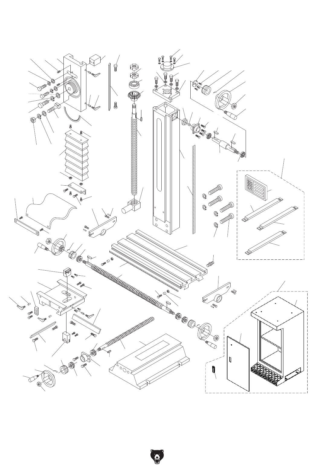
Column & Stand
Please Note: We do our best to stock replacement parts whenever possible, but we cannot guarantee that all parts shown here
are available for purchase. Call (800) 523-4777 or visit our online parts store at www.grizzly.com to check for availability.
2
3
3
4
5
6
7
8
9
10
11
20
21
22
52
58
59
60
44
64 65
61
63
62
76
100-3
100-2
100-1
100
75
74
51
60
60
44
59
71
70
16
16
72
73
57
66
67
68
69
14
15
39
58
40
57
51
19
19
19
50
2324
12
1
49
48
30
29
28
27
26
25
16
13
14 15 17
18
19
31
31-1
32
33
47 46
34
35 36 37 39
38
40
41
45 3644 44
43
42
7 77
54
55
56
39
412
412-1
412-2
412-3
412-4

Model G0759 (Mfd. Since 1/14) -5-
Column & Stand
REF PART # DESCRIPTION REF PART # DESCRIPTION
1 P0759001 Z-AXIS SLIDE 43 P0759043 Z-AXIS HANDWHEEL SHAFT
2 P0759002 SET SCREW M6-1 X 16 44 P0759044 KEY 4 X 4 X 12
3 P0759003 FLAT WASHER 8MM 45 P0759045 PILLOW BLOCK
4 P0759004 LOCK WASHER 8MM 46 P0759046 SPACER
5 P0759005 CAP SCREW M8-1.25 X 25 47 P0759047 PINION GEAR
6 P0759006 FLAT WASHER 12MM 48 P0759048 COLUMN
7 P0759007 LOCK WASHER 12MM 49 P0759049 Z-AXIS SCALE
8 P0759008 CAP SCREW M12-1.75 X 40 50 P0759050 THREADED SLEEVE M6-1 X 16
9 P0759009 T-BOLT M10-1.5 51 P0759051 CAP SCREW M6-1 X 14
10 P0759010 FLAT WASHER 10MM 52 P0759052 X-AXIS LEADSCREW BRACKET (LH)
11 P0759011 LOCK WASHER 10MM 54 P0759054 TABLE
12 P0759012 HEX NUT M10-1.5 55 P0759055 COOLANT HOSE FITTING
13 P0759013 SLIDE ALIGNMENT BLOCK 56 P0759056 X-AXIS LEADSCREW BRACKET (RH)
14 P0759014 LOCK PLUNGER, BRASS 57 P0759057 TABLE HANDWHEEL HANDLE M6-1 X 10
15 P0759015 ADJUSTABLE HANDLE M8-1.25 X 20 58 P0759058 TABLE HANDWHEEL
16 P0759016 GIB ADJUSTMENT SCREW 59 P0759059 TABLE GRADUATED DIAL
17 P0759017 Z-AXIS GIB 60 P0759060 THRUST BEARING 51200
18 P0759018 HEADSTOCK ANGLE SCALE 61 P0759061 CAP SCREW M6-1 X 10
19 P0759019 CAP SCREW M5-.8 X 10 62 P0759062 LIMIT STOP
20 P0759020 Z-AXIS WAY COVER 63 P0759063 T-NUT M6-1
21 P0759021 HEX NUT M5-.8 64 P0759064 X-AXIS SCALE
22 P0759022 Z-AXIS WAY COVER BRACKET 65 P0759065 X-AXIS LEADSCREW
23 P0759023 Y-AXIS WAY COVER 66 P0759066 X-AXIS LEADSCREW NUT
24 P0759024 Y-AXIS WAY COVER BRACKET 67 P0759067 CAP SCREW M4-.7 X 20
25 P0759025 Z-AXIS LEADSCREW LOCK NUT 68 P0759068 SADDLE
26 P0759026 THRUST BEARING 51203 69 P0759069 TABLE STOP BLOCK
27 P0759027 BEVEL GEAR 70 P0759070 Y-AXIS GIB
28 P0759028 KEY 4 X 4 X 16 71 P0759071 Y-AXIS LEADSCREW NUT
29 P0759029 Z-AXIS LEADSCREW 72 P0759072 X-AXIS GIB
30 P0759030 Z-AXIS LEADSCREW NUT 73 P0759073 CAP SCREW M6-1 X 25
31 P0759031 CAP SCREW M5-.8 X 12 74 P0759074 X-AXIS BEARING HOUSING
31-1 P0759031-1 FLAT WASHER 5MM 75 P0759075 X-AXIS LEADSCREW
32 P0759032 BEARING COVER 76 P0759076 BASE
33 P0759033 CAP SCREW M8-1.25 X 20 77 P0759077 CAP SCREW M12-1.75 X 90
34 P0759034 COLUMN TOP PLATE 100 P0759100 STAND ASSEMBLY
35 P0759035 COLLAR FLANGE 100-1 P0759100-1 STAND CABINET
36 P0759036 CAP SCREW M5-.8 X 12 100-2 P0759100-2 STAND DOOR
37 P0759037 Z-AXIS GRADUATED DIAL 100-3 P0759100-3 STAND DOOR LATCH
38 P0759038 Z-AXIS HANDWHEEL 412 P0759412 X/Z-AXIS DRO ASSEMBLY
39 P0759039 HANDWHEEL CURVED PLATE SPRING 412-1 P0759412-1 DRO DISPLAY
40 P0759040 HEX NUT M8-1.25 412-2 P0759412-2 X-AXIS DRO SCALE
41 P0759041 Z-AXIS HANDWHEEL HANDLE M6-1 X 10 412-3 P0759412-3 Y-AXIS DRO SCALE
42 P0759042 BALL BEARING 6001ZZ 412-4 P0759412-4 Z-AXIS DRO SCALE
-6- Model G0759 (Mfd. Since 1/14)
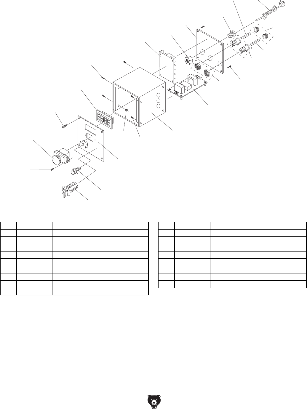
Electrical Box
83
84
79
85
89
88
92
96
86
91
91
91
81
86
87
80
80-1
78
94
90
94
93
95
REF PART # DESCRIPTION REF PART # DESCRIPTION
78 P0759078 CIRCUIT BOARD JD-014 5WR02J 88 P0759088 ELECTRICAL BOX
79 P0759079 POTENTIOMETER W/ KNOB WX14-12 89 P0759089 CAP SCREW M5-.8 X 8
80 P0759080 CAP SCREW M3-.5 X 16 90 P0759090 ELECTRICAL BOX REAR COVER
80-1 P0759080-1 HEX NUT M3-.5 91 P0759091 FUSE HOLDER
81 P0759081 CIRCUIT BOARD CESX 1101-28 92 P0759092 FUSE 15A 250V FAST-ACTING, GLASS
83 P0759083 ON/OFF SWITCH KEDU KJD-178/120V 93 P0759093 POWER CORD 18G 3W 72" 5-15
84 P0759084 CAP SCREW M4-.7 X 10 94 P0759094 STRAIN RELIEF M20 X 1.5 TYPE-3
85 P0759085 CONTROL PANEL PLATE 95 P0759095 FWD/REV SWITCH KEDU EN61058
86 P0759086 CAP SCREW M4-.7 X 6 96 P0759096 FUSE 10A 250V FAST-ACTING, GLASS
87 P0759087 RPM DIGITAL DISPLAY ZD-SX-THL
Model G0759 (Mfd. Since 1/14) -7-
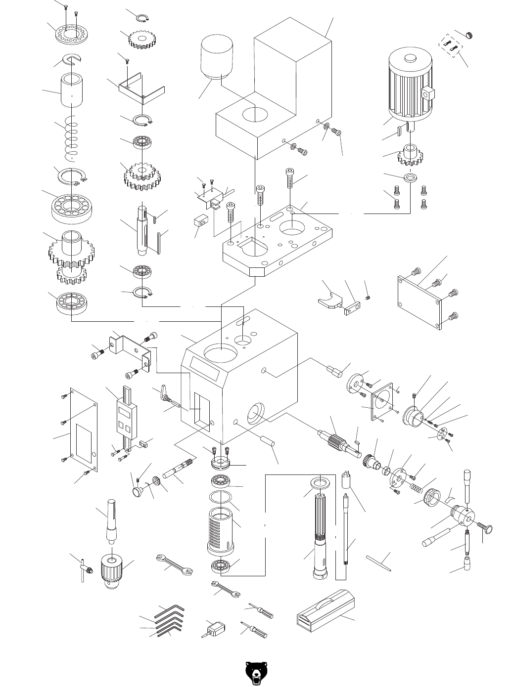
Headstock
206-2
206-1
201
202
225
226
225-2 225-1
208
209
209-2
209-1
210
211
212
213
211
210
207
206
205
204
203
219
220
215
214
240
239
228
229
230
231
221
221-1
221-2
222
223
224
227
216 217 218
254
247
251
248
250
249
296 246
246-1
265
264
263
262 261
260
259
258
257
256
255
255-1
243
243
293
294
295
242
241 232
276
233 235 252
236
237
244
245
234
275 274
266
273
272 271
270
269
268
267
276
240
246-2
292
238
234-1
234-2
401
402
403
404 405
406
407 408
409
411
410

-8- Model G0759 (Mfd. Since 1/14)
Headstock
REF PART # DESCRIPTION REF PART # DESCRIPTION
201 P0759201 QUILL RETAINING CLIP 243 P0759243 HANDWHEEL CURVED PLATE SPRING
202 P0759202 BUSHING 244 P0759244 FINE DOWNFEED GRADUATED DIAL
203 P0759203 COMPRESSION SPRING 245 P0759245 WORM SHAFT
204 P0759204 EXT RETAINING RING 45MM 246-1 P0759246-1 DRAWBAR 7/16-20 x 9-11/16
205 P0759205 BALL BEARING 6209ZZ 246-2 P0759246-2 DRAWBAR RETAINER CAP
206 P0759206 COMBO GEAR 60/70T 246 P0759246 SPINDLE R8
206-1 P0759206-1 SPINDLE RING 16MM 247 P0759247 SPINDLE RING
206-2 P0759206-2 CAP SCREW M3-.5 X 8 248 P0759248 TAPERED ROLLER BEARING 32005
207 P0759207 ANGULAR CONTACT BEARING 7007-2RS 249 P0759249 QUILL
208 P0759208 EXT RETAINING RING 15MM 250 P0759250 QUILL SEAL, RUBBER (UPPER)
209 P0759209 GEAR 37T 251 P0759251 PRELOAD ADJUSTER NUT
209-1 P0759209-1 GEAR GUARD 252 P0759252 ADJUSTER SCREW M5-.8 X 10
209-2 P0759209-2 CAP SCREW M3-.5 X 6 254 P0759254 DOWEL PIN 6 X 30
210 P0759210 EXT RETAINING RING 32MM 255 P0759255 DOWNFEED LEVER M10-1.5 X 14
211 P0759211 BALL BEARING 6002ZZ 255-1 P0759255-1 DOWNFEED LEVER GRIP M10-1.5
212 P0759212 COMBO GEAR 42/62T 256 P0759256 KNOB BOLT M8-1.25 X 30
213 P0759213 SHAFT 257 P0759257 COARSE DOWNFEED HUB
214 P0759214 KEY 5 X 5 X 50 258 P0759258 DOWNFEED GRADUATED DIAL
215 P0759215 KEY 5 X 5 X 12 259 P0759259 COMPRESSION SPRING
216 P0759216 FORK 260 P0759260 CAP SCREW M4-.7 X 40
217 P0759217 FORK ARM 261 P0759261 DOWNFEED FLANGE
218 P0759218 SET SCREW M5-.8 X 8 262 P0759262 BUSHING
219 P0759219 DRAWBAR CAP 263 P0759263 WORM GEAR
220 P0759220 MOTOR COVER V2.11.12 264 P0759264 KEY 4 X 4 X 12
221 P0759221 MOTOR 750W 110VDC 265 P0759265 GEAR SHAFT 16T
221-1 P0759221-1 CARBON BRUSH 2-PC SET 266 P0759266 RIVET 2 X 5MM NAMEPLATE, STEEL
221-2 P0759221-2 CARBON BRUSH CAP 1-PC 267 P0759267 HI/LO INDICATOR PLATE
222 P0759222 FLAT WASHER 4MM 268 P0759268 SET SCREW M8-1.25 X 8
223 P0759223 CAP SCREW M4-.7 X 8 269 P0759269 COMPRESSION SPRING
224 P0759224 CAP SCREW M6-1 X 14 270 P0759270 STEEL BALL 6.5MM
225 P0759225 SPEED SENSOR BRACKET 271 P0759271 HI/LO HANDWHEEL
225-1 P0759225-1 SPEED SENSOR CORD 272 P0759272 SET SCREW M5-.8 X 16
225-2 P0759225-2 CAP SCREW M3-.5 X 6 273 P0759273 SPEED KNOB PLATE
226 P0759226 SPEED SENSOR 274 P0759274 FORK SHAFT FLANGE
227 P0759227 MOTOR MOUNT 275 P0759275 FORK SHAFT
228 P0759228 CAP SCREW M5-.8 X 12 276 P0759276 CAP SCREW M3-.5 X 16
229 P0759229 MOTOR GEAR RING 292 P0759292 SPINDLE PIN
230 P0759230 GEAR 20T 293 P0759293 DRILL CHUCK ARBOR R8 X B16
231 P0759231 KEY 4 X 4 X 6 294 P0759294 DRILL CHUCK B16 3-16MM
232 P0759232 SET SCREW M5-.8 X 6 295 P0759295 DRILL CHUCK KEY 1/4" STD 11T SD-3/4"
233 P0759233 CAP SCREW M3-.5 X 6 296 P0759296 TAPERED ROLLER BEARING 32007
234 P0759234 Z-AXIS DRO ASSEMBLY 401 P0759401 HEX WRENCH 6MM
234-1 P0759234-1 Z-AXIS DRO BRACKET 402 P0759402 HEX WRENCH 5MM
234-2 P0759234-2 CAP SCREW M4-.7 X 10 403 P0759403 HEX WRENCH 4MM
235 P0759235 Z-AXIS DRO SLIDE MOUNT 404 P0759404 HEX WRENCH 3MM
236 P0759236 ADJUSTABLE HANDLE M8-1.25 X 20 405 P0759405 HEX WRENCH 2MM
237 P0759237 LOCK PLUNGER, BRASS 406 P0759406 WRENCH 8 X 10MM OPEN-ENDS
238 P0759238 HEADSTOCK CASTING 407 P0759407 WRENCH 17 X 19MM OPEN-ENDS
239 P0759239 HEADSTOCK REAR COVER 408 P0759408 SCREWDRIVER FLAT #2
240 P0759240 CAP SCREW M4-.7 X 8 409 P0759409 SCREWDRIVER PHILLIPS #2
241 P0759241 FINE FEED KNOB 410 P0759410 BOTTLE FOR OIL
242 P0759242 HEADSTOCK FRONT COVER 411 P0759411 TOOLBOX
Model G0759 (Mfd. Since 1/14) -9-
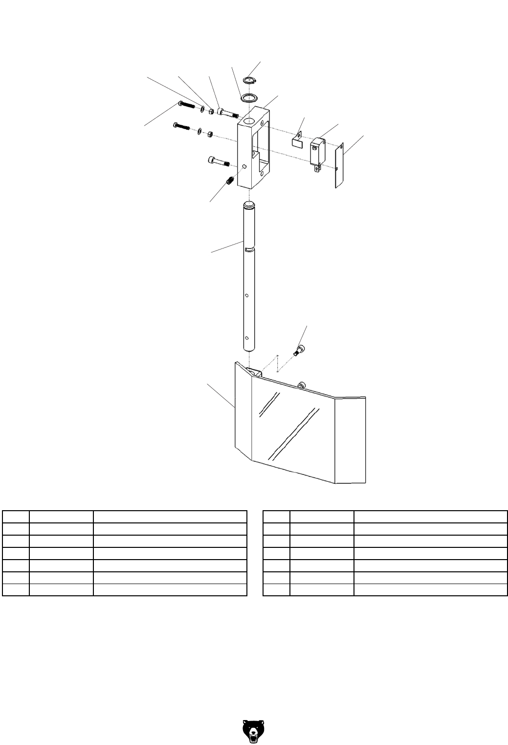
Chip Guard
297
277 278 279
280
281
282
283 284
285
286
287
288
289
REF PART # DESCRIPTION REF PART # DESCRIPTION
277 P0759277 FLAT WASHER 3MM 284 P0759284 LIMIT SWITCH DATER KW1-103
278 P0759278 HEX NUT M3-.5 285 P0759285 PROTECTIVE PAPER
279 P0759279 CAP SCREW M4-.7 X 20 286 P0759286 SET SCREW M5-.8 X 10
280 P0759280 EXT RETAINING RING 12MM 287 P0759287 CHIP GUARD POST
281 P0759281 WAVY WASHER 20MM 288 P0759288 CHIP GUARD
282 P0759282 GUARD MOUNTING BLOCK 289 P0759289 CAP SCREW M4-.7 X 18
283 P0759283 LIMIT SWITCH L-BRACKET, COPPER 297 P0759297 CAP SCREW M3-.5 X 16
-10- Model G0759 (Mfd. Since 1/14)
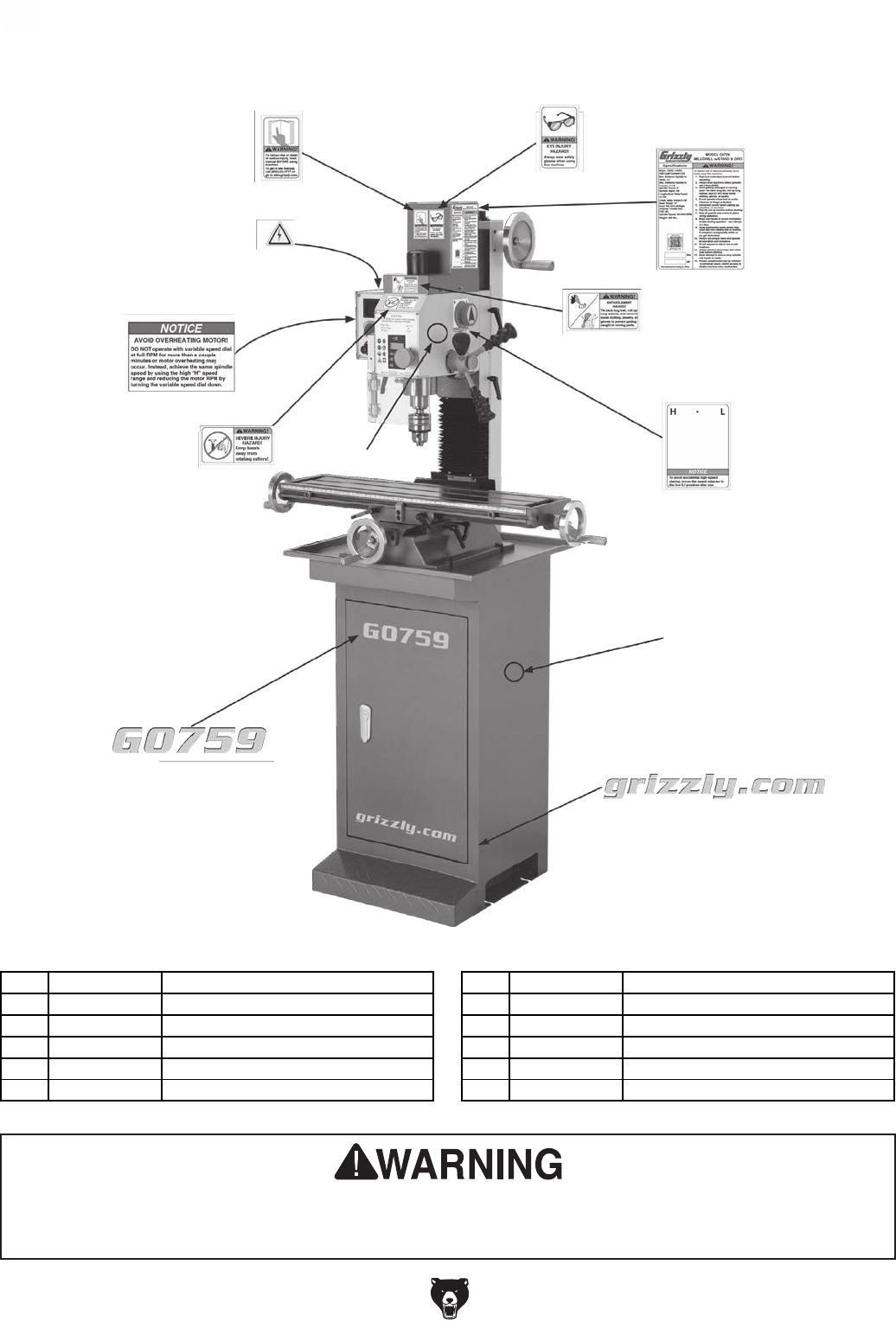
Labels
Safety labels help reduce the risk of serious injury caused by machine hazards. If any label comes
off or becomes unreadable, the owner of this machine MUST replace it in the original location
before resuming operations. For replacements, contact (800) 523-4777 or www.grizzly.com.
REF PART # DESCRIPTION REF PART # DESCRIPTION
301 P0759301 READ MANUAL LABEL 307 P0759307 GRIZZLY GREEN TOUCH-UP PAINT
302 P0759302 SAFETY GLASSES LABEL 308 P0759308 CUTTER WARNING LABEL
303 P0759303 MACHINE ID LABEL 309 P0759309 ENTANGLEMENT LABEL
304 P0759304 HIGH/LOW SPEED LABEL 310 P0759310 AVOID OVERHEATING LABEL
305 P0759305 GRIZZLY PUTTY TOUCH-UP PAINT 311 P0759311 GRIZZLY.COM LABEL
306 P0759306 MODEL NUMBER LABEL 312 P0759312 ELECTRICITY LABEL
301 302
303
304
305
306
307
308
309
310
311
312
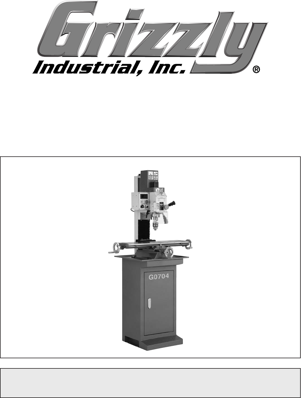
MODEL G0704
MILL/DRILL WITH STAND
OWNER'S MANUAL
COPYRIGHT © FEBRUARY, 2010 BY GRIZZLY INDUSTRIAL, INC. REVISED FEBRUARY, 2013 (TR)
WARNING: NO PORTION OF THIS MANUAL MAY BE REPRODUCED IN ANY SHAPE
OR FORM WITHOUT THE WRITTEN APPROVAL OF GRIZZLY INDUSTRIAL, INC.
(FOR MODELS MANUFACTURED SINCE 08/11) #JB12468 PRINTED IN CHINA

This manual provides critical safety instructions on the proper setup,
operation, maintenance, and service of this machine/tool. Save this
document, refer to it often, and use it to instruct other operators.
Failure to read, understand and follow the instructions in this manual
may result in fire or serious personal injury—including amputation,
electrocution, or death.
The owner of this machine/tool is solely responsible for its safe use.
This responsibility includes but is not limited to proper installation in
a safe environment, personnel training and usage authorization,
proper inspection and maintenance, manual availability and compre-
hension, application of safety devices, cutting/sanding/grinding tool
integrity, and the usage of personal protective equipment.
The manufacturer will not be held liable for injury or property damage
from negligence, improper training, machine modifications or misuse.
Some dust created by power sanding, sawing, grinding, drilling, and
other construction activities contains chemicals known to the State
of California to cause cancer, birth defects or other reproductive
harm. Some examples of these chemicals are:
• Lead from lead-based paints.
• Crystalline silica from bricks, cement and other masonry products.
• Arsenic and chromium from chemically-treated lumber.
Your risk from these exposures varies, depending on how often you
do this type of work. To reduce your exposure to these chemicals:
Work in a well ventilated area, and work with approved safety equip-
ment, such as those dust masks that are specially designed to filter
out microscopic particles.
Table of Contents
INTRODUCTION ............................................... 2
Manual Accuracy ........................................... 2
Contact Info.................................................... 2
Machine Description ...................................... 2
Identification ................................................... 3
Electronic Controls Identification ................... 4
SECTION 1: SAFETY ....................................... 8
Safety Instructions for Machinery .................. 8
Additional Safety for Mill/Drills ..................... 10
SECTION 2: POWER SUPPLY ...................... 11
SECTION 3: SETUP ....................................... 13
Needed for Setup ......................................... 13
Unpacking .................................................... 13
Inventory ...................................................... 14
Cleanup ........................................................ 15
Site Considerations ...................................... 16
Moving & Placing Machine .......................... 17
Mounting to Shop Floor ............................... 18
Assembly ..................................................... 19
Drill Chuck Arbor .......................................... 19
Power Connection........................................ 20
Test Run & Spindle Break-in ....................... 21
SECTION 4: OPERATIONS ........................... 22
Operation Overview ..................................... 22
Basic Controls .............................................. 23
Digital Readout Unit ..................................... 25
Calculating Spindle Speed ........................... 26
Spindle Speed and Direction ....................... 27
Spindle Height Controls ............................... 28
Drill Chuck.................................................... 29
Loading Tooling ........................................... 30
Headstock Travel (Z-Axis and Rotation) ...... 31
Table Travel ................................................. 32
SECTION 5: ACCESSORIES ......................... 33
SECTION 6: MAINTENANCE ......................... 36
Schedule ...................................................... 36
Lubrication ................................................... 36
SECTION 7: SERVICE ................................... 39
Troubleshooting ........................................... 39
Gibs .............................................................. 41
Leadscrew Backlash .................................... 42
Digital Readout Unit Battery Replacement . . 42
Motor Service ............................................... 43
SECTION 8: WIRING ...................................... 44
Wiring Safety Instructions ............................ 44
Wiring Diagram ............................................ 45
Electrical Components ................................. 46
SECTION 9: PARTS ....................................... 47
Column Breakdown...................................... 47
Column Parts List ........................................ 48
Electrical Box Breakdown & Parts List ........ 49
Headstock Breakdown ................................. 50
Headstock Parts List .................................... 51
Chip Guard Breakdown & Parts List ............ 52
Labels Breakdown & Parts List .................... 53
WARRANTY AND RETURNS ........................ 57
-2- Model G0704 (Mfg. Since 0 8/11)
INTRODUCTION
Machine Description
We stand behind our machines. If you have
any questions or need help, use the information
below to contact us. Before contacting, please get
the serial number and manufacture date of your
machine. This will help us help you faster.
Grizzly Technical Support
1203 Lycoming Mall Circle
Muncy, PA 17756
Phone: (570) 546-9663
Email: techsupport@grizzly.com
We want your feedback on this manual. What did
you like about it? Where could it be improved?
Please take a few minutes to give us feedback.
Grizzly Documentation Manager
P.O. Box 2069
Bellingham, WA 98227-2069
Email: manuals@grizzly.com
Contact Info
We are proud to offer this manual with your new
machine! We've made every effort to be exact
with the instructions, specifications, drawings,
and photographs of the machine we used when
writing this manual. However, sometimes we still
make
an occasional mistake.
Also, owing to our policy of continuous improve-
ment, your machine may not exactly match the
manual
.
If you find this to be the case, and the dif-
ference between the manual and machine leaves
you in doubt,
check our website for the latest
manual update or call technical support for help.
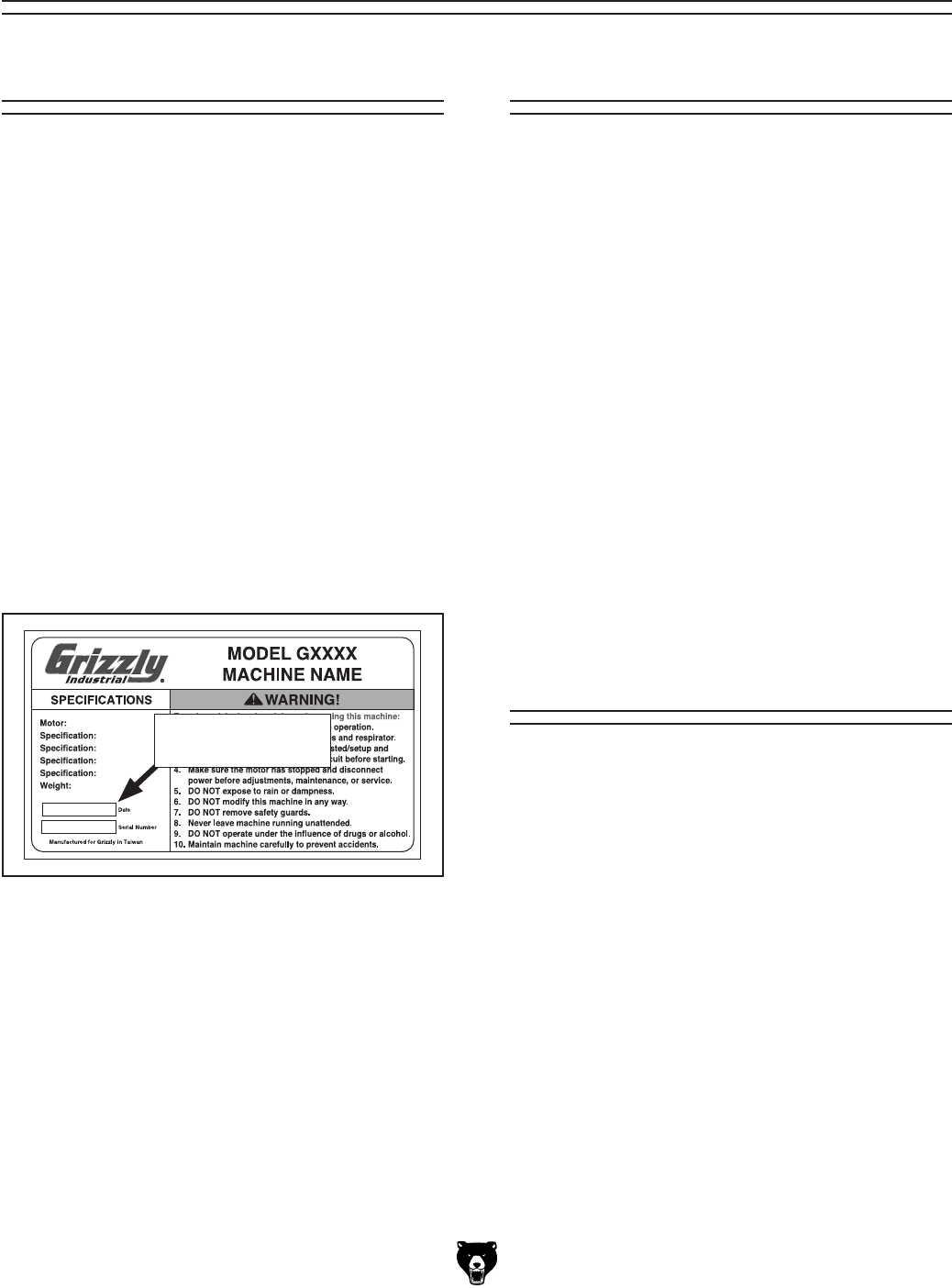
Before calling, find the manufacture date of your
machine by looking at the date stamped into the
machine ID label (see below). This will help us
determine if the manual version you received
matches the manufacture date of your machine.
For your convenience, we
post all available man
-
uals and
manual updates for free
on our website
at
www.grizzly.com. Any updates to your
model
of
machine will be reflected in these documents
as soon as they are complete.
Manufacture Date
of Your Machine
Manual Accuracy
The mill/drill is used to shape metal and solid
workpieces by removing material with the use of
a rotating cutting tool.
In milling operations, the cutting tool remains sta-
tionary while the workpiece is drawn across it by
moving the table.
In drilling operations, the workpiece is held sta-
tionary on the table while the cutting tool moves
up-and-down with the movement of the spindle
and head.
Model G0704 (Mfg. Since 0 8/11)-3-
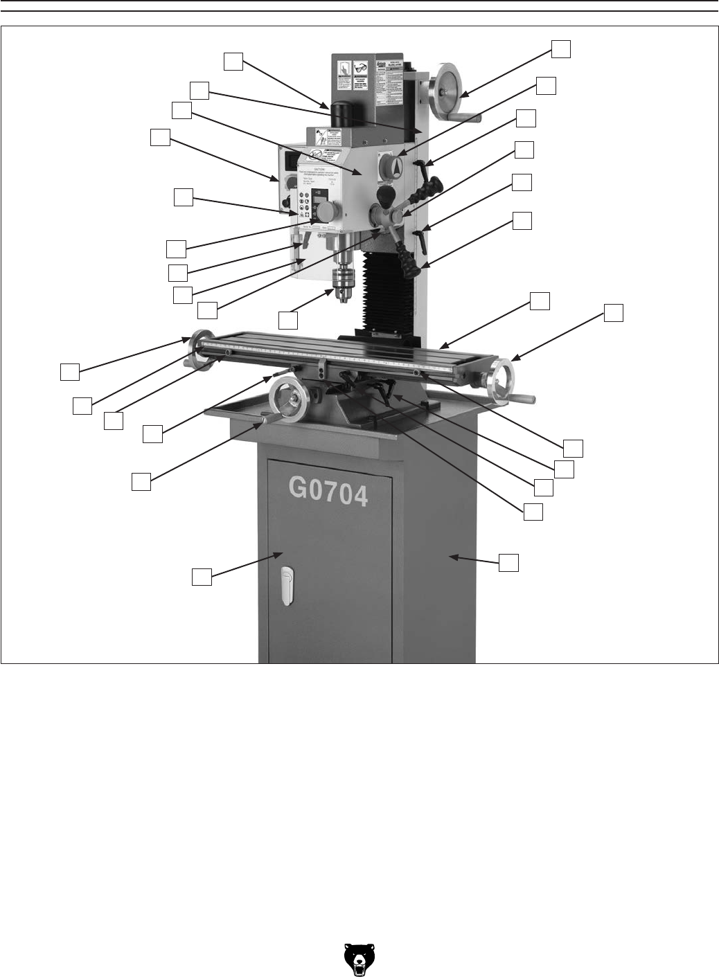
Identification
Figure 1. G0704 Identification.
A. Drawbar Cap and Drawbar
B. Vertical (Z-Axis) Handwheel
C. Speed Range Selector Knob
D. Vertical Travel Lock
E. Fine Feed Lock Knob
F. Quill Feed Lever
G. Table
H. Longitudinal (X-Axis) Handwheel
I. Longitudinal Table Stop
J. Table Cross Travel Locks
K. Table Longitudinal Travel Lock
L. Table Center Stop
M. Machine Stand
N. Storage Access Door
O. Cross (Y-Axis) Handwheel
P. Longitudinal Scale
Q. Drill Chuck
R. Headstock Tilt Scale
S. Chip Guard
T. Quill Lock Lever
U. Fine Feed Knob
V. Digital Readout (Page 4)
W. Control Panel (Page 4)
X. Headstock
Y. Column
H
H
AB
R
S
P
O
N
I
I
L
J
M
W
X
Y
V
U
G
F
D
D
C
E
K
K
T
Q
-4- Model G0704 (Mfg. Since 0 8 /11)
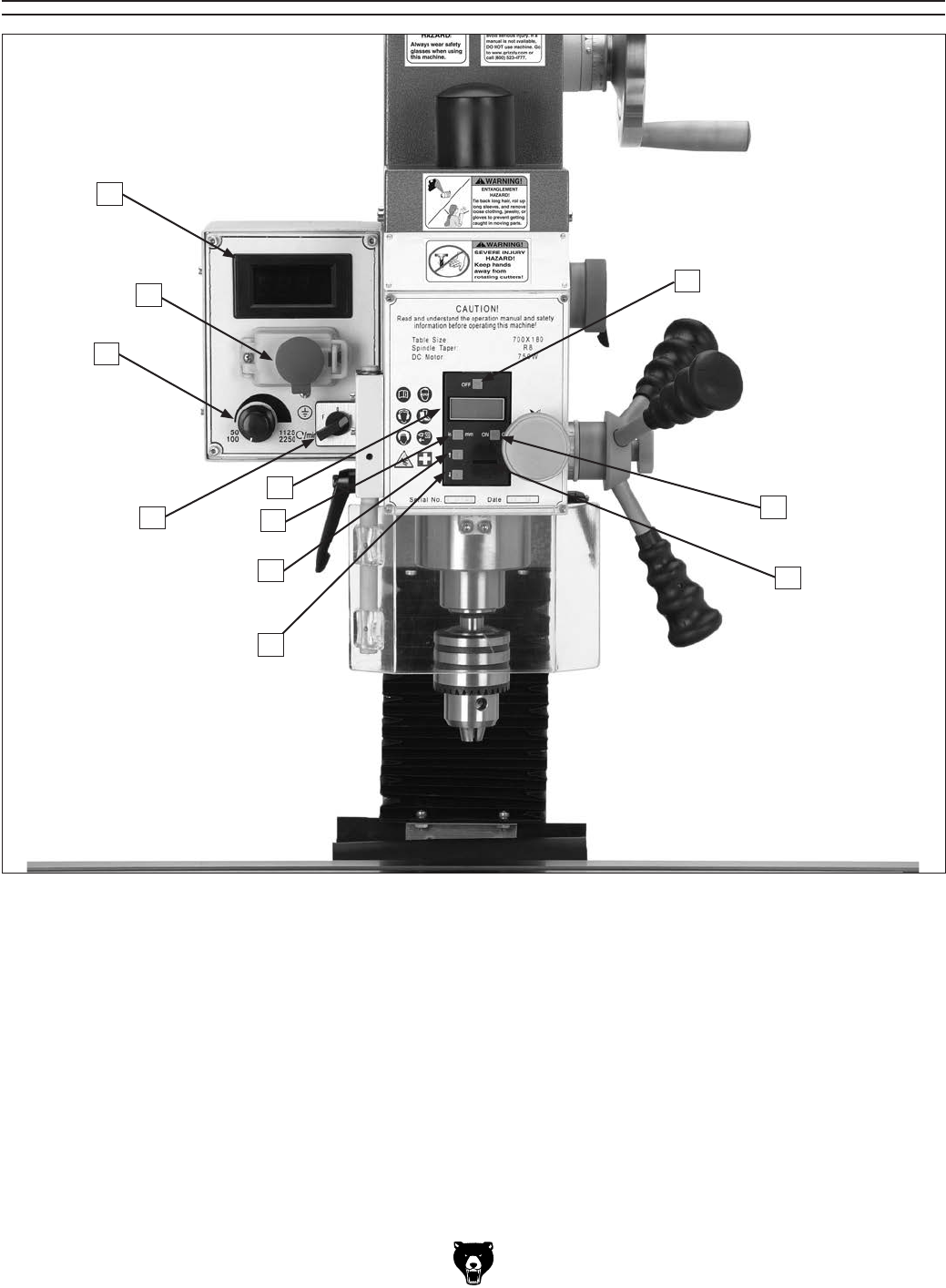
Electronic Controls Identification
Figure 2. G0704 electronic controls identification.
A. Spindle RPM Readout
B. Spindle Digital Readout OFF Button
C. Digital Readout ON/ZERO Button
D. Digital Readout Battery Cover & Battery
E. Spindle Depth Display DECREASE Button
F. Spindle Depth Display INCREASE Button
G. IN/MM Unit Selection Button
H. Spindle Depth Display
I. Spindle Direction Selection Knob
J. Variable Spindle Speed Knob
K. START/Emergency STOP Buttons
H
A
B
I
K
J
G
FD
C
E

Model G0704 (Mfg. Since 0 8/11)-5-
The information contained herein is deemed accurate as of 3/3/2014 and represents our most recent product specifications.
Due to our ongoing improvement efforts, this information may not accurately describe items previously purchased. PAGE 1 OF 3Model G0704
MACHINE DATA
SHEET
Customer Service #: (570) 546-9663 · To Order Call: (800) 523-4777 · Fax #: (800) 438-5901
MODEL G0704 DRILL/MILL WITH STAND
Product Dimensions:
Weight.............................................................................................................................................................. 265 lbs.
Width (side-to-side) x Depth (front-to-back) x Height........................................................................... 38 x 24 x 31 in.
Footprint (Length x Width)............................................................................................................... 15-3/4 x 16-1/2 in.
Space Required for Full Range of Movement (Width x Depth).................................................................... 57 x 25 in.
Shipping Dimensions:
Carton #1
Type................................................................................................................................................ Wood Crate
Content................................................................................................................................................. Machine
Weight.................................................................................................................................................... 295 lbs.
Length x Width x Height............................................................................................................. 30 x 28 x 36 in.
Carton #2
Type........................................................................................................................................... Cardboard Box
Content...................................................................................................................................................... Stand
Weight...................................................................................................................................................... 77 lbs.
Length x Width x Height............................................................................................................. 17 x 17 x 33 in.
Electrical:
Power Requirement........................................................................................................... 110V, Single-Phase, 60 Hz
Prewired Voltage.................................................................................................................................................. 110V
Full-Load Current Rating........................................................................................................................................ 12A
Minimum Circuit Size.............................................................................................................................................. 15A
Connection Type....................................................................................................................................... Cord & Plug
Power Cord Included.............................................................................................................................................. Yes
Power Cord Length................................................................................................................................................. 6 ft.
Power Cord Gauge......................................................................................................................................... 16 AWG
Plug Included.......................................................................................................................................................... Yes
Included Plug Type................................................................................................................................................ 5-15
Switch Type........................................................................................... ON/OFF Push Button Switch w/Safety Cover
Motors:
Main
Type..................................................................................................................................................... Universal
Horsepower................................................................................................................................................ 1 HP
Phase............................................................................................................................................ Single-Phase
Amps............................................................................................................................................................ 12A
Speed................................................................................................................................................ 4300 RPM
Power Transfer ................................................................................................................................. Gear Drive
Bearings..................................................................................................... Shielded & Permanently Lubricated

-6- Model G0704 (Mfg. Since 08 /11)
The information contained herein is deemed accurate as of 3/3/2014 and represents our most recent product specifications.
Due to our ongoing improvement efforts, this information may not accurately describe items previously purchased. PAGE 2 OF 3Model G0704
Main Specifications:
Operation Info
Spindle Travel.............................................................................................................................................. 2 in.
Max Distance Spindle to Column.......................................................................................................... 7-1/2 in.
Max Distance Spindle to Table.................................................................................................................. 13 in.
Longitudinal Table Travel (X-Axis)...................................................................................................... 18-7/8 in.
Cross Table Travel (Y-Axis).................................................................................................................. 6-7/8 in.
Vertical Head Travel (Z-Axis)..................................................................................................................... 11 in.
Head Tilt (Left/Right).............................................................................................................................. 90 deg.
Drilling Capacity for Cast Iron................................................................................................................... 3/4 in.
Drilling Capacity for Steel......................................................................................................................... 5/8 in.
End Milling Capacity................................................................................................................................. 3/4 in.
Face Milling Capacity............................................................................................................................ 2-1/2 in.
Table Info
Table Length........................................................................................................................................ 26-5/8 in.
Table Width......................................................................................................................................... 7-1/16 in.
Table Thickness.................................................................................................................................... 1-3/4 in.
Number of T-Slots............................................................................................................................................ 3
T-Slot Size................................................................................................................................................ 1/2 in.
T-Slots Centers...................................................................................................................................... 2-1/2 in.
Spindle Info
Spindle Taper............................................................................................................................................... R-8
Number of Vertical Spindle Speeds...................................................................................................... Variable
Range of Vertical Spindle Speeds............................................................................................. 50 – 2250 RPM
Quill Diameter......................................................................................................................................... 2.36 in.
Drawbar Thread Size............................................................................................................................. 7/16-20
Drawbar Length................................................................................................................................. 9-11/16 in.
Spindle Bearings......................................................................................................... Tapered Roller Bearings
Construction
Spindle Housing/Quill........................................................................................................................... Cast Iron
Table....................................................................................................................... Precision-Ground Cast Iron
Head.................................................................................................................................................... Cast Iron
Column/Base....................................................................................................................................... Cast Iron
Base..................................................................................................................................................... Cast Iron
Stand.......................................................................................................................................................... Steel
Paint....................................................................................................................................................... Enamel
Other Specifications:
Country Of Origin ............................................................................................................................................... China
Warranty ........................................................................................................................................................... 1 Year
Approximate Assembly & Setup Time .............................................................................................................. 1 Hour
Serial Number Location ...................................................................................................... ID Label on Head Casting
Sound Rating ..................................................................................................................................................... 80 dB
ISO 9001 Factory .................................................................................................................................................. Yes
CSA Certified .......................................................................................................................................................... No
Features:
Digital spindle scale reads metric, inches, zero, set, on/off
Forward/reverse switch
Chip guard
Digital display for spindle speed
Dovetail column
Front mounted fine feed knob
Coolant trough

Model G0704 (Mfg. Since 0 8/11)-7-
The information contained herein is deemed accurate as of 3/3/2014 and represents our most recent product specifications.
Due to our ongoing improvement efforts, this information may not accurately describe items previously purchased. PAGE 3 OF 3Model G0704
Accessories Included:
Drill chuck 3–16mm with B16 taper
Drill chuck arbor B16 x R8
Two T-bolts
Two open-ended combo wrenches
Chuck key
Oil bottle
Extra fuse
Hex wrenches
Standard and Phillips screwdrivers
Tool box

-8- Model G0704 (Mfg. Since 0 8/11)
ELECTRICAL EQUIPMENT INJURY RISKS. You
can be shocked, burned, or killed by touching live
electrical components or improperly grounded
machinery. To reduce this risk, only allow qualified
service personnel to do electrical installation or
repair work, and always disconnect power before
accessing or exposing electrical equipment.
DISCONNECT POWER FIRST.
Always discon-
nect machine from power supply BEFORE making
adjustments, changing tooling, or servicing machine.
This prevents an injury risk from unintended startup
or contact with live electrical components.
EYE PROTECTION. Always wear ANSI-approved
safety glasses or a face shield when operating or
observing machinery to reduce the risk of eye
injury or blindness from flying particles. Everyday
eyeglasses are not approved safety glasses.
OWNER’S MANUAL. Read and understand this
owner’s manual BEFORE using machine.
TRAINED OPERATORS ONLY. Untrained oper-
ators have a higher risk of being hurt or killed.
Only allow trained/supervised people to use this
machine. When machine is not being used, dis-
connect power, remove switch keys, or lock-out
machine to prevent unauthorized use—especially
around children. Make workshop kid proof!
DANGEROUS ENVIRONMENTS. Do not use
machinery in areas that are wet, cluttered, or have
poor lighting. Operating machinery in these areas
greatly increases the risk of accidents and injury.
MENTAL ALERTNESS REQUIRED. Full mental
alertness is required for safe operation of machin-
ery. Never operate under the influence of drugs or
alcohol, when tired, or when distracted.
For Your Own Safety, Read Instruction
Manual Before Operating This Machine
The purpose of safety symbols is to attract your attention to possible hazardous conditions.
This manual uses a series of symbols and signal words intended to convey the level of impor-
tance of the safety messages. The progression of symbols is described below. Remember that
safety messages by themselves do not eliminate danger and are not a substitute for proper
accident prevention measures. Always use common sense and good judgment.
Indicates a potentially hazardous situation which, if not avoided,
MAY result in minor or moderate injury. It may also be used to alert
against unsafe practices.
Indicates a potentially hazardous situation which, if not avoided,
COULD result in death or serious injury.
Indicates an imminently hazardous situation which, if not avoided,
WILL result in death or serious injury.
This symbol is used to alert the user to useful information about
proper operation of the machine.
NOTICE
Safety Instructions for Machinery
SECTION 1: SAFETY

Model G0704 (Mfg. Since 0 8/11)-9-
WEARING PROPER APPAREL. Do not wear
clothing, apparel or jewelry that can become
entangled in moving parts. Always tie back or
coverlonghair.Wearnon-slipfootweartoavoid
accidentalslips,whichcouldcauselossofwork-
piececontrol.
hAzARdOus dusT. Dust created while using
machinery may cause cancer, birth defects, or
long-term respiratory damage. Be aware of dust
hazardsassociatedwitheachworkpiecematerial,
andalwayswearaNIOSH-approvedrespiratorto
reduceyourrisk.
hEARING PROTECTION.Alwayswearhear-
ing protection when operating or observing loud
machinery.Extendedexposuretothisnoise
withouthearing protectioncan cause permanent
hearingloss.
REMOVE AdJusTING TOOLs. Tools left on
machinerycanbecomedangerousprojectiles
uponstartup.Neverleavechuckkeys,wrenches,
or any other tools on machine. Always verify
removalbeforestarting!
INTENdEd usAGE. Only use machine for its
intendedpurposeandnevermakemodifications
not approved by Grizzly. Modifying machine or
using it differently than intended may result in
malfunctionormechanicalfailurethatcanleadto
seriouspersonalinjuryordeath!
AWKWARd POsITIONs. Keep proper footing
andbalanceatalltimeswhenoperatingmachine.
Donotoverreach!Avoidawkwardhandpositions
that make workpiece control difficult or increase
theriskofaccidentalinjury.
ChILdREN & BYsTANdERs. Keepchildrenand
bystandersatasafedistancefromtheworkarea.
Stopusingmachineiftheybecomeadistraction.
GuARds & COVERs.Guardsandcoversreduce
accidental contact with moving parts or flying
debris. Make sure they are properly installed,
undamaged,andworkingcorrectly.
FORCING MAChINERY.Donotforcemachine.
Itwill do the job saferand better at the ratefor
whichitwasdesigned.
NEVER sTANd ON MAChINE. Serious injury
may occur if machine is tipped or if the cutting
toolisunintentionallycontacted.
sTABLE MAChINE. Unexpectedmovementdur-
ing operation greatly increases risk of injury or
lossofcontrol.Beforestarting,verifymachineis
stableandmobilebase(ifused)islocked.
usE RECOMMENdEd ACCEssORIEs.Consult
thisowner’smanualorthemanufacturerforrec-
ommended accessories. Using improper acces-
sorieswillincreasetheriskofseriousinjury.
uNATTENdEd OPERATION. Toreducethe
risk of accidental injury, turn machine off and
ensure all moving parts completely stop before
walkingaway.Neverleavemachinerunning
whileunattended.
MAINTAIN WITh CARE.Followallmaintenance
instructions and lubrication schedules to keep
machine in good working condition. A machine
that is improperly maintained could malfunction,
leadingtoseriouspersonalinjuryordeath.
ChECK dAMAGEd PARTs. Regularly inspect
machine for any condition that may affect safe
operation.Immediatelyrepairorreplacedamaged
ormis-adjustedpartsbeforeoperatingmachine.
MAINTAIN POWER CORds. When disconnect-
ing cord-connected machines frompower,grab
andpulltheplug—NOTthecord.Pullingthecord
maydamage the wires inside.Donothandle
cord/plugwithwethands.Avoidcorddamageby
keepingitawayfromheatedsurfaces,hightraffic
areas,harshchemicals,andwet/damplocations.
EXPERIENCING dIFFICuLTIEs. Ifatanytime
youexperiencedifficultiesperformingtheintend-
edoperation,stopusingthemachine!Contactour
TechnicalSupportat(570)546-9663.

-10- Model G0704 (Mfg. Since 0 8/11)
Additional Safety for Mill/Drills
UNDERSTANDING CONTROLS. Make sure you
understand the use and operation of all controls.
SAFETY ACCESSORIES. Always use a chip
guard in addition to your safety glasses when mill-
ing/drilling to prevent bodily injury.
WORK HOLDING. Before starting the machine,
be certain the workpiece has been properly
clamped to the table. NEVER hold the workpiece
by hand when using the mill/drill.
CHUCK KEY SAFETY. Always remove your
chuck key, drawbar wrench, and any service tools
immediately after use.
SPINDLE SPEEDS. Select the spindle speed
that is appropriate for the type of work and mate-
rial. Allow the mill/drill to gain full speed before
beginning a cut.
POWER DISRUPTION. In the event of a local
power outage during use of the mill, drill turn OFF
all switches to avoid possible sudden start up
once power is restored.
SPINDLE DIRECTION CHANGES. Never reverse
spindle direction while the spindle is turning.
MACHINE CARE AND MAINTENANCE. Never
operate the mill/drill with damaged or worn parts.
Maintain your mill/drill in proper working condition.
Perform routine inspections and maintenance
promptly. Put away adjustment tools after use.
STOPPING SPINDLE. DO NOT stop the mill/drill
using your hand against the chuck.
BE ATTENTIVE. DO NOT leave the mill/drill run-
ning unattended for any reason.
DISCONNECT POWER. Make sure the mill/drill is
turned OFF, disconnected from its power source
and all moving parts have come to a complete
stop before starting any inspection, adjustment,
or maintenance procedure.
AVOIDING ENTANGLEMENT. Keep loose cloth-
ing articles such as sleeves, belts or jewelry items
away from the spindle. Never wear gloves when
operating the mill/drill.
TOOL HOLDING. Always use the proper tools
for the material you are machining. Make sure
they are held firmly in the proper tool holder for
the job.
CLE AN - U P. DO NOT clear chips by hand. Use a
brush, and never clear chips while the spindle is
turning.
CUTTING TOOL INSPECTION. Inspect drills and
end mills for sharpness, chips, or cracks before
each use. Replace dull, chipped, or cracked cut-
ting tools immediately. Handle new cutting tools
with care. Leading edges are very sharp and can
cause lacerations.
EXPERIENCING DIFFICULTIES. If at any time
you are experiencing difficulties performing the
intended operation, stop using the machine!
Contact our Technical Support at (570) 546-
9663.
No list of safety guidelines can be complete. Every shop environment is different. Like all
machines there is danger associated with the Model G0704. Accidents are frequently caused by
lack of familiarity or failure to pay attention. Use this machine with respect and caution to lessen
the possibility of operator injury. If normal safety precautions are overlooked or ignored, serious
personal injury may occur.
Model G0704 (Mfg. Since 0 8/11)-11-
SECTION 2: POWER SUPPLY
Availability
Before installing the machine, consider the avail-
ability and proximity of the required power supply
circuit. If an existing circuit does not meet the
requirements for this machine, a new circuit must
be installed. To minimize the risk of electrocution,
fire, or equipment damage, installation work and
electrical wiring must be done by an electrican or
qualified service personnel in accordance with all
applicable codes and standards.
Electrocution, fire, or
equipment damage may
occur if machine is not
correctly grounded and
connected to the power
supply.
Full-Load Current Rating
The full-load current rating is the amperage a
machine draws at 100% of the rated output power.
On machines with multiple motors, this is the
amperage drawn by the largest motor or sum of all
motors and electrical devices that might operate
at one time during normal operations.
Full-Load Current Rating at 110V ..... 3.2 Amps
The full-load current is not the maximum amount
of amps that the machine will draw. If the machine
is overloaded, it will draw additional amps beyond
the full-load rating.
If the machine is overloaded for a sufficient length
of time, damage, overheating, or fire may result—
especially if connected to an undersized circuit.
To reduce the risk of these hazards, avoid over-
loading the machine during operation and make
sure it is connected to a power supply circuit that
meets the requirements in the following section.
For your own safety and protection of
property, consult an electrician if you are
unsure about wiring practices or electrical
codes in your area.
Circuit Requirements
Note: The circuit requirements listed in this man-
ual apply to a dedicated circuit—where only one
machine will be running at a time. If this machine
will be connected to a shared circuit where mul-
tiple machines will be running at the same time,
consult a qualified electrician to ensure that the
circuit is properly sized for safe operation.
A power supply circuit includes all electrical
equipment between the breaker box or fuse panel
in the building and the machine. The power sup-
ply circuit used for this machine must be sized to
safely handle the full-load current drawn from the
machine for an extended period of time. (If this
machine is connected to a circuit protected by
fuses, use a time delay fuse marked D.)
This machine is prewired to operate on a 110V
power supply circuit that has a verified ground and
meets the following requirements:
Nominal Voltage ............................... 110V/120V
Cycle ..........................................................60 Hz
Phase ........................................... Single-Phase
Power Supply Circuit ......................... 15 Amps
-12- Model G0704 (Mfg. Since 0 8/11)
Improper connection of the equipment-grounding
wire can result in a risk of electric shock. The
wire with green insulation (with or without yellow
stripes) is the equipment-grounding wire. If repair
or replacement of the power cord or plug is nec-
essary, do not connect the equipment-grounding
wire to a live (current carrying) terminal.
Check with a qualified electrician or service per-
sonnel if you do not understand these grounding
requirements, or if you are in doubt about whether
the tool is properly grounded. If you ever notice
that a cord or plug is damaged or worn, discon-
nect it from power, and immediately replace it with
a new one.
Extension Cords
We do not recommend using an extension cord
with this machine.
If you must use an extension
cord, only use it if absolutely necessary and only
on a temporary basis.
Extension cords cause voltage drop, which may
damage electrical components and shorten motor
life. Voltage drop increases as the extension cord
size gets longer and the gauge size gets smaller
(higher gauge numbers indicate smaller sizes).
Any extension cord used with this machine must
contain a ground wire, match the required plug
and receptacle, and meet the following require-
ments:
Minimum Gauge Size ...........................16 AWG
Maximum Length (Shorter is Better).......50 ft.
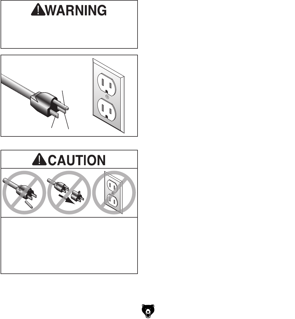
Grounding & Plug Requirements
Figure 3. Typical 5-15 plug and receptacle.
Grounding Prong
Neutral Hot
5-15 PLUG
GROUNDED
5-15 RECEPTACLE
Serious injury could occur if you connect
the machine to power before completing the
setup process. DO NOT connect to power
until instructed later in this manual.
SHOCK HAZARD!
Two-prong outlets do not meet the grounding
requirements for this machine. Do not modify
or use an adapter on the plug provided—if
it will not fit the outlet, have a qualified
electrician install the proper outlet with a
verified ground.
This machine MUST be grounded. In the event
of certain malfunctions or breakdowns, grounding
reduces the risk of electric shock by providing a
path of least resistance for electric current.
This machine is equipped with a power cord that
has an equipment-grounding wire and a ground-
ing plug (similar to the figure below). The plug
must only be inserted into a matching receptacle
(outlet) that is properly installed and grounded in
accordance with all local codes and ordinances.
Model G0704 (Mfg. Since 0 8/11)-13-
SECTION 3: SETUP
The following are needed to complete the setup
process, but are not included with your machine:
Description Qty
• Precision Level ........................................... 1
• Safety Glasses (for each person) ............... 1
• Standard Screwdriver #3 ............................ 1
• Solvent/Cleaner .......................................... 1
• Shop Rags .................................................. 1
• Metal Shim Stock ....................................... 1
• Brass Hammer ........................................... 1
• Lifting Strap (Rated for at least 500 lbs.) .... 1
• Lifting Equipment
(Rated for at least 500 lbs.) ........................ 1
• An Assistant ............................................... 1
Needed for Setup
Wear safety glasses dur-
ing the entire set up pro-
cess!
This machine presents
serious injury hazards
to untrained users. Read
through this entire manu-
al to become familiar with
the controls and opera-
tions before starting the
machine!
The Model G0704 is a
heavy machine. Serious
personal injury may occur
if safe moving meth-
ods are not used. To be
safe, get assistance and
use power equipment to
move the shipping crate
and remove the machine
from the crate.
Your machine was carefully packaged for safe
transportation. Remove the packaging materials
from around your machine and inspect it. If you
discover any damage, please call us immediately
at (570) 546-9663
for advice.
Save the containers and all packing materials for
possible inspection by the carrier or its agent.
Otherwise, filing a freight claim can be difficult.
When you are completely satisfied with the condi-
tion of your shipment, inventory the contents.
Unpacking
SUFFOCATION HAZARD!
Keep children and pets away
from plastic bags or packing
materials shipped with this
machine. Discard immediately.
-14- Model G0704 (Mfg. Since 0 8 /11)
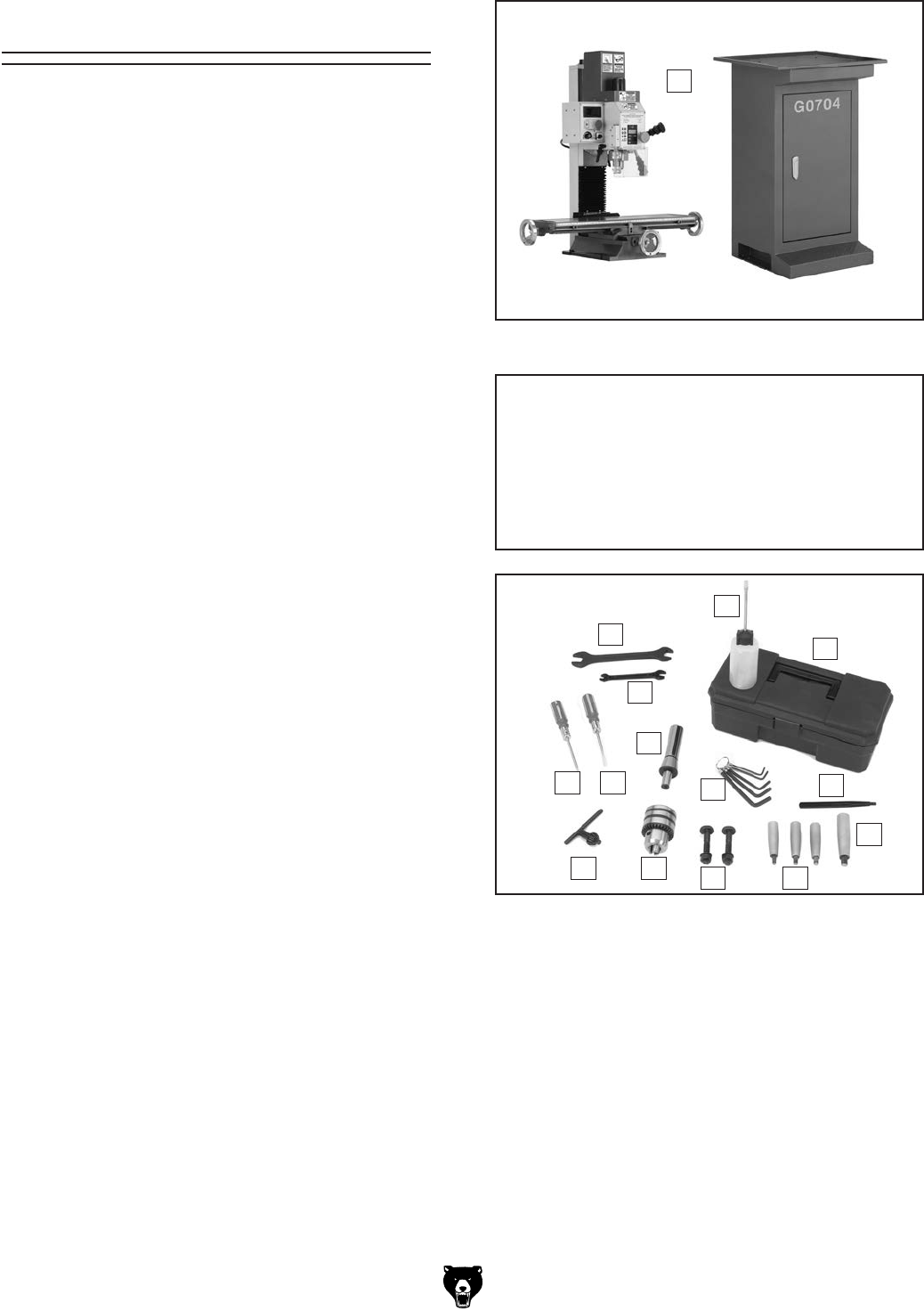
Inventory
Contents Qty
A. Mill/Drill w/Stand ......................................... 1
B. Open End Combo Wrench 17/19 ................ 1
C. Open End Combo Wrench 8/10 ................. 1
D. Bottle for Oil ............................................... 1
E. Tool Box...................................................... 1
F. Large Handwheel Handle ........................... 1
G. Small Handwheel Handles ......................... 3
H. T-Bolts M10-1.5 x 60 (vise mounting) ......... 2
Flat Washers 10mm (vise mounting) .......... 2
Hex Nuts M10-1.5 (vise mounting).............. 2
I. Drill Chuck .................................................. 1
J. Chuck Key .................................................. 1
K. Phillips Screwdriver .................................... 1
L. Flat Screwdriver .......................................... 1
M. Arbor B16 x R8 ........................................... 1
N. Hex Wrench Set 2, 3, 4, 5, & 6mm ...... 1 ea.
O. Spindle Pin ................................................. 1
Not Shown:
Hex Bolts M10-1.5 x 50 .............................. 4
Flat Washers 10mm ................................... 4
Figure 4. G0704 out of the crate.
A
Figure 5. Inventory.
B
D
E
GH
IJ
LK
M
C
F
NO
The following is a list of items shipped with your
machine. Before beginning setup, lay these items
out and inventory them.
If any non-proprietary parts are missing (e.g. a
nut or a washer), we will gladly replace them; or
for the sake of expediency, replacements can be
obtained at your local hardware store.
NOTICE
If you cannot find an item on this list, care-
fully check around/inside the machine and
packaging materials. Often, these items get
lost in packaging materials while unpack-
ing or they are pre-installed at the factory.

Model G0704 (Mfg. Since 0 8/11)-15-
The unpainted surfaces of your machine are
coated with a heavy-duty rust preventative that
prevents corrosion during shipment and storage.
This rust preventative works extremely well, but it
will take a little time to clean.
Be patient and do a thorough job cleaning your
machine. The time you spend doing this now will
give you a better appreciation for the proper care
of your machine's unpainted surfaces.
There are many ways to remove this rust preven
-
tative, but the following steps work well in a wide
variety of situations. Always follow the manufac
-
turer’s instructions with any cleaning product you
use and make sure you work in a well-ventilated
area to minimize exposure to toxic fumes.
Before cleaning, gather the following:
•
Disposable Rags
•
Cleaner/degreaser (WD•40 works well)
•
Safety glasses & disposable gloves
•
Plastic paint scraper (optional)
Basic steps for removing rust preventative:
1.
Put on safety glasses.
2.
Coat the rust preventative with a liberal
amount of cleaner/degreaser, then let it soak
for 5–10 minutes.
3.
Wipe off the surfaces. If your cleaner/degreas-
er is effective, the rust preventative will wipe
off easily. If you have a plastic paint scraper,
scrape off as much as you can first, then wipe
off the rest with the rag.
4.
Repeat Steps 2–3 as necessary until clean,
then coat all unpainted surfaces with a quality
metal protectant to prevent rust.
Gasoline or products
with low flash points can
explode or cause fire if
used to clean machin-
ery. Avoid cleaning with
these products.
Many cleaning solvents
are toxic if concentrat-
ed amounts are inhaled.
Only work in a well-venti-
lated area.
NOTICE
Avoid chlorine-based solvents, such as
acetone or brake parts cleaner, that may
damage painted surfaces. Test all cleaners
in an inconspicuous area before using to
make sure they will not damage paint.
Cleanup
-16- Model G0704 (Mfg. Since 0 8/11)
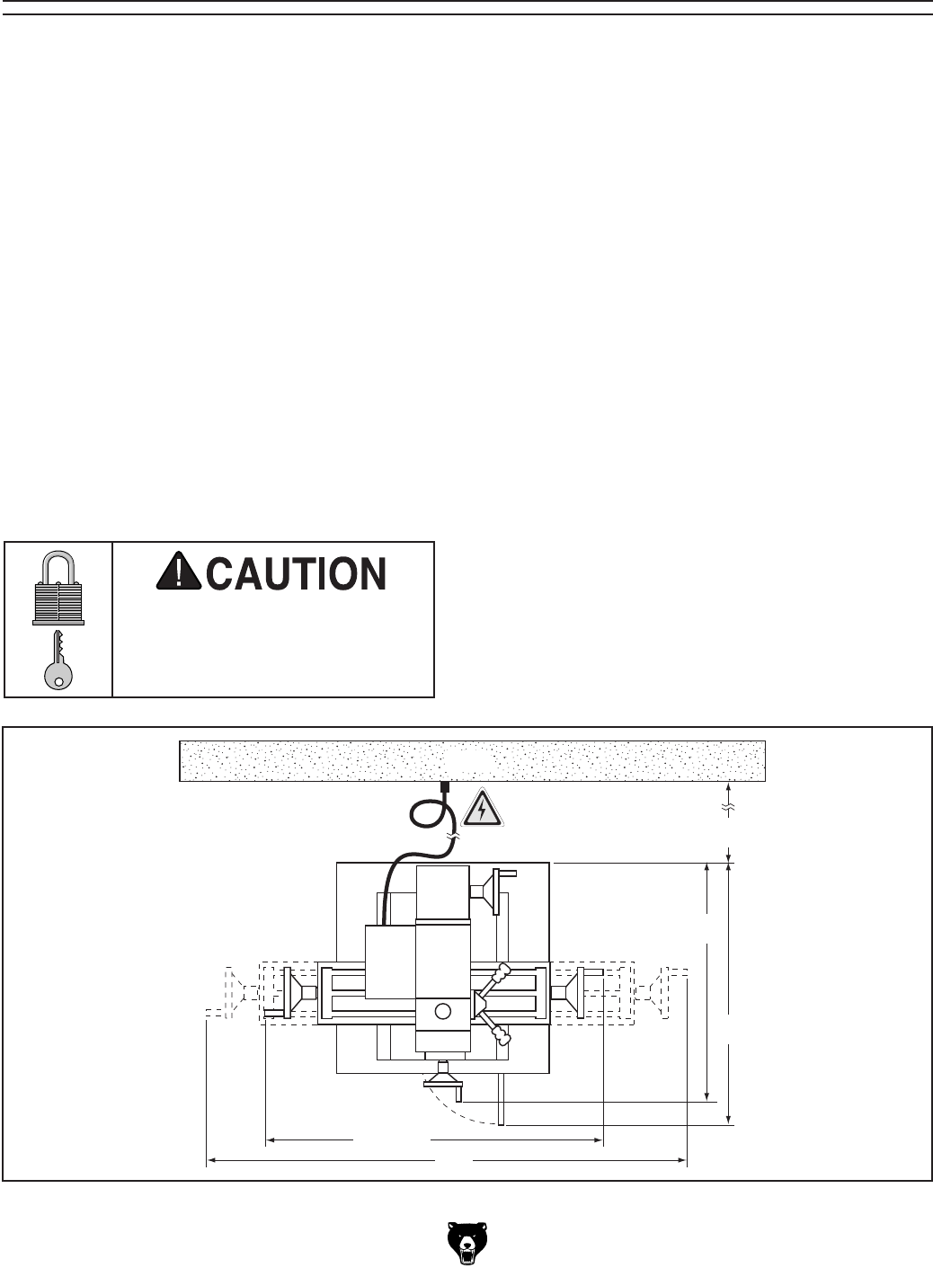
Site Considerations
Figure 6. Space required for full machine range of motion.
Weight Load
Refer to the Machine Data Sheet for the weight
of your machine. Make sure that the surface upon
which the machine is placed will bear the weight
of the machine, additional equipment that may be
installed on the machine, and the heaviest work-
piece that will be used. Additionally, consider the
weight of the operator and any dynamic loading
that may occur when operating the machine.
Space Allocation
Consider the largest size of workpiece that will
be processed through this machine and provide
enough space around the machine for adequate
operator material handling or the installation of
auxiliary equipment. With permanent installations,
leave enough space around the machine to open
or remove doors/covers as required by the main-
tenance and service described in this manual.
See below for required space allocation.
Physical Environment
The physical environment where the machine is
operated is important for safe operation and lon-
gevity of machine components. For best results,
operate this machine in a dry environment that is
free from excessive moisture, hazardous chemi-
cals, airborne abrasives, or extreme conditions.
Extreme conditions for this type of machinery are
generally those where the ambient temperature
range exceeds 41°–104°F; the relative humidity
range exceeds 20–95% (non-condensing); or the
environment is subject to vibration, shocks, or
bumps.
Electrical Installation
Place this machine near an existing power source.
Make sure all power cords are protected from
traffic, material handling, moisture, chemicals,
or other hazards. Make sure to leave access to
a means of disconnecting the power source or
engaging a lockout/tagout device, if required.
Lighting
Lighting around the machine must be adequate
enough that operations can be performed safely.
Shadows, glare, or strobe effects that may distract
or impede the operator must be eliminated.
Children or untrained people
may be seriously injured by
this machine. Only install in an
access restricted location.
57"
25"
30"
Wall
37.25"
24"
Model G0704 (Mfg. Since 0 8/11)-17-
To remove your machine from the shipping
crate and place it in position:
1. Place the crate adjacent to the location where
your machine will be placed, then remove the
shipping crate from the pallet.
2. Position the stand into the desired location.
3. Use the vertical handwheel to raise the head-
stock as far as possible.
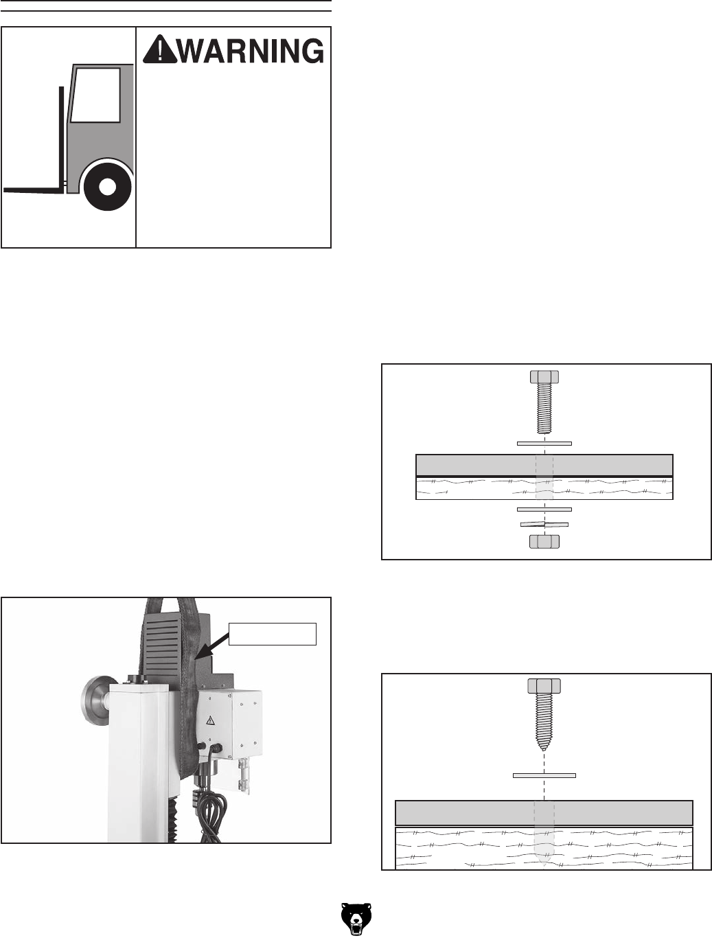
4. Hang a lifting strap from the fork of a forklift
and place it under the head of the mill/drill, as
shown in Figure 7. Take care not to place the
straps over any controls that may be dam-
aged during transit.
Figure 7. Lifting strap.
Moving & Placing
Machine
The Model G0704 is a
heavy machine. Serious
personal injury may occur
if safe moving methods
are not used. To be safe,
get assistance and use
power equipment to move
the shipping crate and
remove the machine from
the crate.
5. Unbolt the machine from the pallet, then with
an assistant steadying the machine to pre-
vent it from swinging, lift it slightly off of the
pallet. Use the cross handwheel to move the
table forward or backward as necessary to
balance the machine so it hangs as close to
level as possible.
6. Lift the machine and carefully place it onto
the stand.
7. Bolt the machine to the stand with the four
M10-1.25 x 50 hex bolts and flat washers.
—If you are placing the machine on a work-
bench, it must be securely mounted to the
workbench surface.
The strongest mounting option is a "Through
Mount" where holes are drilled all the way
through the workbench, and hex bolts, wash-
ers, and hex nuts are used to secure the
machine to the workbench.
Machine Base
Workbench
Hex
Bolt
Flat Washer
Flat Washer
Lock Washer
Hex Nut
Figure 8. Example of a through mount setup.
Machine Base
Workbench
Lag Screw
Flat Washer
Figure 9. Example of a direct mount setup.
Another option for mounting is a "Direct Mount"
where the machine is simply secured to the work-
bench with a lag screw.
Lifting Strap
-18- Model G0704 (Mfg. Since 0 8 /11)
Although not required, we recommend that you
mount your new machine cabinet to the floor.
Because this is an optional step and floor mate-
rials may vary, floor mounting hardware is not
included. Generally, you can either bolt the cabi-
net to the floor or mount it on machine mounts.
Both options are described below. Whichever
option you choose, it is necessary to level the
cabinet with a precision level.
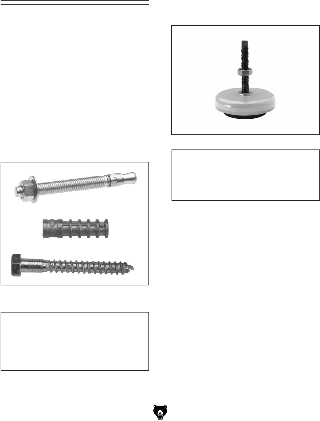
Bolting to Concrete Floors
Lag shield anchors with lag bolts and anchor
studs (Figure 10) are two popular methods for
anchoring an object to a concrete floor. We sug-
gest you research the many options and methods
for mounting your machine and choose the best
that fits your specific application.
Mounting to Shop
Floor
Figure 10. Typical fasteners for mounting to
concrete floors.
NOTICE
Anchor studs are stronger and more per-
manent alternatives to lag shield anchors;
however, they will stick out of the floor,
which may cause a tripping hazard if you
decide to move your machine.
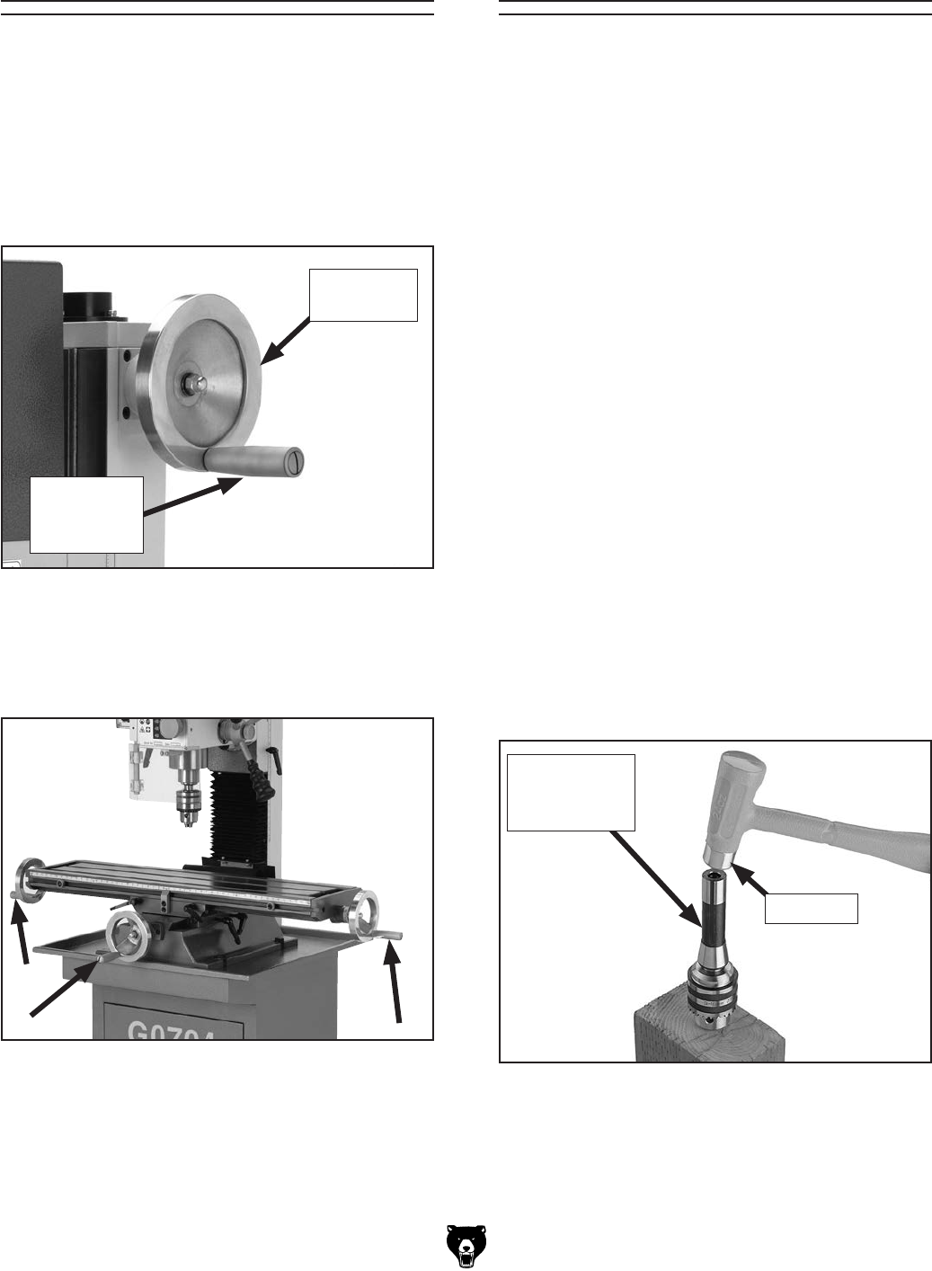
Figure 11. Machine mount example.
Using Machine Mounts
Using machine mounts, shown in Figure 11, gives
the advantage of fast leveling and vibration reduc-
tion. The large size of the foot pads distributes
the weight of the machine to reduce strain on the
floor.
NOTICE
We strongly recommend securing your
machine to the floor if it is hardwired to the
power source. Consult with your electrician
to ensure compliance with local codes.
Model G0704 (Mfg. Since 0 8/11)-19 -
Assembly
Assembly of the Model G0704 consists of attach-
ing the four handwheel handles to the machine.
To assemble your machine:
1. With a #3 standard screwdriver, install the
large handwheel handle on the elevation
handwheel (Figure 12).
2. Use the same method to install the three
small handwheel handles to the three table
travel handwheels (Figure 13).
Figure 13. Table handwheel handles.
Figure 12. Elevation handwheel handle.
Elevation
Handwheel
Elevation
Handwheel
Handle
Your machine includes an B-16 drill chuck arbor
and drill chuck. Before use, the drill chuck must
be installed onto the arbor. The This drill chuck
installation is intended to be semi-permanent.
Tip: For a permanent installation, chill the arbor
in the freezer for 15 minutes before performing the
following procedure. The taper will expand as it
returns to room temperature, permanently locking
the chuck.
To install the drill chuck onto the arbor:
1. Clean the grease off the drill chuck and all
taper mating surfaces. Pay particular atten-
tion to the B-16 bore in the drill chuck—it
must be free from all grease, oil, and debris.
2. Retract the drill chuck jaws fully by turning the
body of the drill chuck counterclockwise.
3. Insert the arbor into the drill chuck. Tap the
arbor lightly with a brass or other soft-headed
hammer to get a good fit.
Note: While it may not seem like there is
anything keeping the drill chuck in place, the
B-16 Taper fit provides a strong bond and will
hold the drill chuck tightly (Figure 14).
Figure 14. Drill chuck.
R-8 Arbor w/
B-16 Chuck
Taper
Brass Tip
Drill Chuck Arbor
4. Refer to Page 29 for detailed instructions
for installing or removing the drill chuck and
arbor in the spindle.
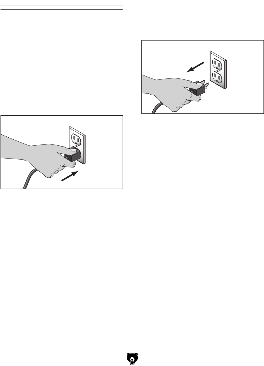
-20- Model G0704 (Mfg. Since 0 8/11)
Power Connection
After you have completed all previous setup
instructions and circuit requirements, the machine
is ready to be connected to the power supply.
To avoid unexpected startups or property dam-
age, use the following steps whenever connecting
or disconnecting the machine.
Connecting Power
Figure 15. Connecting power.
1. TurnthemachinepowerswitchOFF.
2.
Insert the power cord plug into a
matching
power supply receptacle. The machine
is
nowconnectedtothepowersource.
Disconnecting Power
Figure 16. Disconnecting power.
1. TurnthemachinepowerswitchOFF.
2.
Graspthemoldedplugandpullit
completely
outofthereceptacle.Donotpullbythe
cord
asthismaydamagethewiresinside.
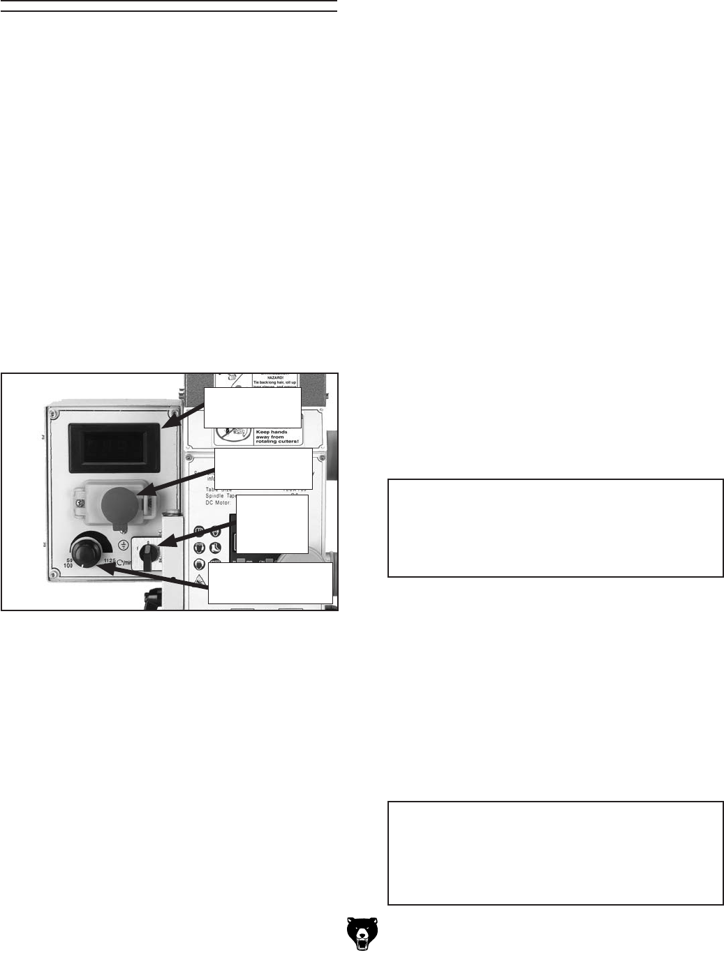
Model G0704 (Mfg. Since 0 8/11)-21-
Test Run & Spindle
Break-in
The Model G0704 spindle speed can be set from
50–2250 RPM. You must follow the proper break-
in procedures to ensure the spindle bearings
break-in and seat before putting any milling load
on the machine.
To test run and break-in the spindle bearings:
1. Do all lubrication procedures highlighted in
Lubrication in Section 6: MAINTENANCE
on Page 36.
2. Make sure there are no obstructions around
or underneath the spindle.
3. Place the spindle direction selection knob in
the "0" (OFF) position and press the emer-
gency STOP button (Figure 17)
Figure 17. Test run controls.
4. Connect the mill/drill to the power source.
5. Turn the speed range selector knob to the
"L" (low) position (Figure 1 on Page 3) and
rotate the variable spindle speed knob all the
way to the left (slowest) position.
6. Place the spindle direction knob in the "F"
(Forward) position. Squeeze the tab on the
emergency STOP button, pull it open, then
press the green button. The spindle will begin
to turn at a low RPM.
Emergency
STOP Button
Variable Spindle
Speed Knob
Spindle
Direction
Knob
Spindle RPM
Readout
Failure to follow start up and spindle break-
in procedures will likely cause rapid deteri-
oration of spindle and other related parts.
NOTICE
10. Increase the speed to 1000 RPM and let it
run for another ten minutes.
11. Increase the speed to 2200 RPM and let it
run for another ten minutes.
12. Turn the mill/drill OFF.
13. Set the spindle to rotate in the opposite direc-
tion, then press the green button and let it run
at 1000 RPM for another ten minutes.
DO NOT leave the area while break-in pro-
cedure is under way. You must be ready to
stop the machine if a problem occurs.
NOTICE
—When operating correctly, the machine
runs smoothly with little or no vibration or
rubbing noises.
— Investigate and correct strange or unusual
noises or vibrations before operating the
machine further. Always disconnect the
machine from power when investigating or
correcting potential problems.
7. Press the emergency STOP button. The
machine should stop.
—If the machine does stop, the emergency
STOP button safety feature is working cor-
rectly. Continue to Step 8.
—If the machine does not stop, the emer-
gency STOP button safety feature is not
working correctly. This safety feature must
work properly before proceeding with regu-
lar operations. Call Tech Support for help.
8. Open the emergency STOP button cover and
press the green button to start the spindle.
9. While watching the spindle RPM readout,
turn the variable spindle speed knob until the
mill/drill reaches approximately 600 RPM,
then let it run for a minimum of 10 minutes.
-22- Model G0704 (Mfg. Since 0 8 /11)
To complete a typical operation, the operator
does the following:
1. Loosens the vertical travel locks, then adjusts
the headstock height above the table to
ensure there is sufficient room to install the
tooling in the spindle and the workpiece on
the table.
2. Installs the desired tooling for the job.
3. Positions the workpiece as needed for the
operation, then clamps the workpiece using
applicable clamping devices, or a vise that is
already mounted on the table to ensure the
workpiece does not move during the milling/
drilling operation.
4. Positions the cutter or drill bit near the
workpiece, then tightens vertical travel locks.
5. Selects the appropriate spindle speed for the
milling or drilling operation using the speed
selector knob and variable spindle speed
knob.
6. Unlocks the X- and Y-axis table locks.
7. Wears safety glasses or a face shield.
8. Turns the spindle direction selection knob to
the desired direction.
9. Loosens the quill lock lever and uses the quill
feed lever or the fine feed knob to set the cut-
ting tool height according to the workpiece.
10. For milling operations, uses the table
handwheels to move the table so the cutter
removes material evenly from the workpiece.
For drilling operations, uses the quill feed
lever or fine feed knob to lower the drill bit
into the workpiece, then raises the drill bit out
of the workpiece using the same controls.
11. Turns the spindle direction knob to the "0"
position to stop the spindle.
SECTION 4: OPERATIONS
Operation Overview
The purpose of this overview is to provide the nov-
ice machine operator with a basic understanding
of how the machine is used during operation, so
the
machine controls/components
discussed later
in this manual
are easier to understand.
Due to the generic nature of this overview, it is
not intended to be an instructional guide. To learn
more about specific operations, read this entire
manual and
seek additional training from expe
-
rienced
machine operators, and do additional
research outside of this manual by reading "how-
to" books, trade magazines, or websites.
Damage to your eyes and lungs could result
from using this machine without proper pro-
tective gear. Always wear safety glasses and
a respirator when operating this machine.
To reduce the risk of
serious injury when using
this machine, read and
understand this entire
manual before operating.
NOTICE
If you have never used this type of machine
or equipment before, WE STRONGLY REC-
OMMEND that you read books, review
industry trade magazines, or get formal
training before beginning any projects.
Regardless of the content in this section,
Grizzly Industrial will not be held liable for
accidents caused by lack of training.
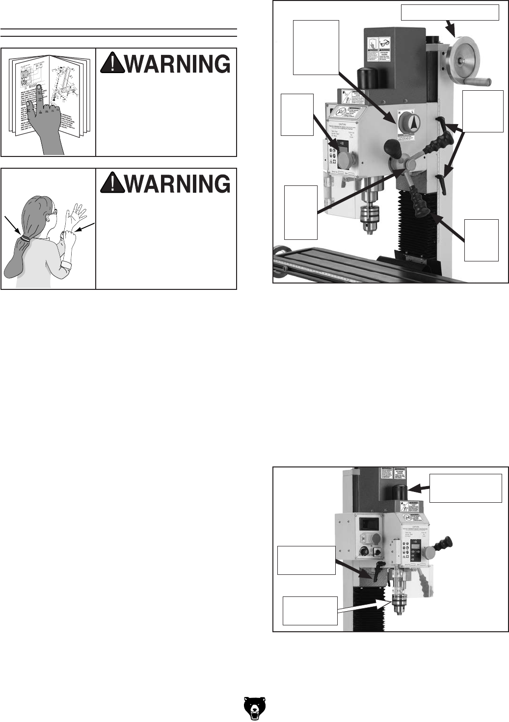
Model G0704 (Mfg. Since 0 8/11)-23-
Basic Controls
Use the descriptions and figures below to become
familiar with the basic controls of your machine.
Vertical Handwheel: Raises and lowers the
headstock (Z-Axis).
Speed Range Selector Knob: Selects low range
(L) or high range (H) for the spindle speed.
Vertical Travel Locks: Lock the position of the
headstock to the column.
Fine Feed Lock Knob: Engages the fine feed
knob for precise control of vertical quill travel.
Fine Feed Knob: Provides fine control over verti-
cal quill travel.
Quill Feed Levers: Provide coarse control over
vertical quill travel.
Figure 18. Head controls.
Vertical
Travel
Locks
Vertical Handwheel
Quill
Feed
Lever
Fine
Feed
Knob
Fine
Feed
Lock
Knob
Speed
Range
Selector
Knob
Drawbar Cap: Covers the drawbar and upper
portion of the spindle.
Drawbar: Secures collets and tooling in the
spindle taper.
Spindle and Chuck: Provide a mounting place
for tooling.
Quill Lock Lever: Locks the vertical position of
the quill when tightened.
Figure 19. Headstock controls (continued).
Quill Lock
Lever
Drawbar Cap
& Drawbar
Spindle &
Chuck
Loose hair, clothing, or
jewelry could get caught
in machinery and cause
serious personal injury.
Keep these items away
from moving parts at all
times to reduce this risk.
To reduce the risk of
serious injury when using
this machine, read and
understand this entire
manual before beginning
any operations.
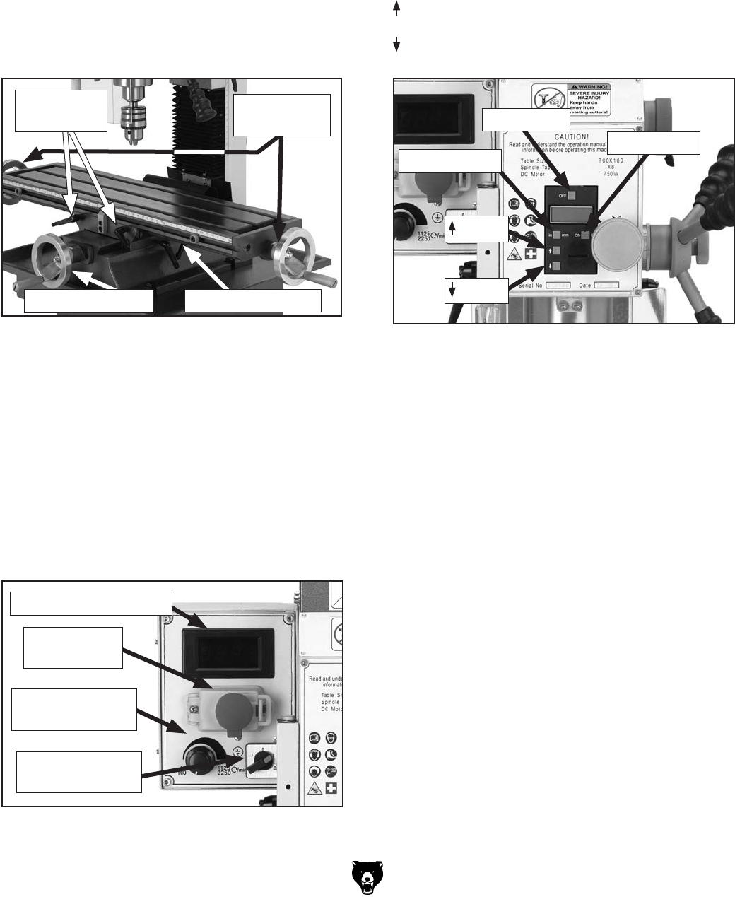
-24- Model G0704 (Mfg. Since 0 8/11)
OFF Button: Turns OFF the display.
ON/0 Button: Turns ON the display with the
first press. Pressed again resets the display to
0.000".
IN/MM Button: Toggles the units displayed.
Button: Increases the current depth reading.
Button: Decreases the current depth reading.
Spindle RPM Readout: Displays the speed of
the spindle rotation.
Emergency STOP Button: Interrupts the flow of
power to the machine.
Variable Spindle Speed Knob: Changes the
speed of the spindle rotation.
Spindle Direction Selection Knob: Changes
the direction of spindle rotation.
Figure 21. Control panel.
Spindle RPM Readout
Emergency
STOP Button
Variable Spindle
Speed Knob
Spindle Direction
Selection Knob
Figure 22. Digital readout unit controls.
ON/0 Button
IN/MM Button
Button
Button
OFF Button
Figure 20. Table controls.
Cross Handwheel: Moves the table forward and
backward (Y-Axis).
Longitudinal Handwheels: Move the table from
side to side (X-Axis).
Longitudinal Table Locks: Lock the longitudinal
position of the table when tightened.
Cross Table Locks: Lock the cross position of
the table when tightened.
Cross Handwheel
Longitudinal
Handwheels
Cross Table Locks
Longitudinal
Table Locks
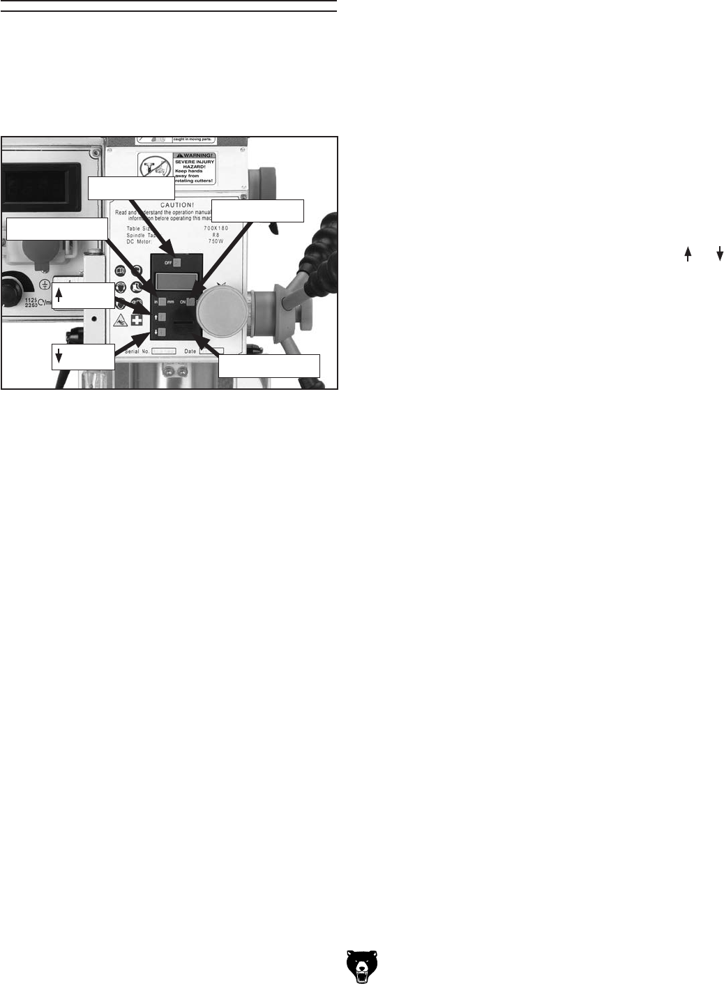
Model G0704 (Mfg. Since 0 8/11)-25-
Digital Readout Unit
The digital readout unit gives a precise reading
of the vertical positioning of the quill. It can be
zeroed at any position and manually increased or
decreased independent of quill position when the
operation requires it (Figure 23).
Figure 23. Digital readout controls.
ON/0 Button
IN/MM Button
Button
Button
OFF Button
Battery Cover
To use the digital readout:
1. Press the ON/0 button. A reading should
appear on the display.
2. Press the IN/MM button to select whether
units will be displayed in inches or millime-
ters. Each press of the button switches from
one unit to the other.
3. If you want to "zero" the readout at any time,
press the ON/0 button. The current reading
will be cleared and the scale will be reset to
0.000.
If you want to increase or decrease the read-
ing at any time, press the appropriate or
button. This is useful when calibrating the mill
to known dimensions on a workpiece.
4. When the operation is complete, press the
OFF button to conserve the battery.

-26- Model G0704 (Mfg. Since 0 8 /11)
Calculating Spindle
Speed
Closely follow the proper spindle speed and
proper feed rate to produce good results, reduce
undue strain on all moving parts and increase
operator safety.
Prior to milling, determine the spindle speed
needed to cut your workpiece, then set the speed
on the machine.
To determine the needed spindle speed:
1. Use the table in Figure 24 to determine the
cutting speed required for the material of your
workpiece.
2. Measure the diameter of your cutting tool in
inches.
3. Use the following formula to determine the
needed spindle RPM for your operation:
(Cutting Speed x 4) /Tool Diameter = RPM
Cutting Speeds for High Speed Steel (HSS)
Cutting Tools
Workpiece Material Cutting Speed (sfm)
Aluminum & Alloys 300
Brass & Bronze 150
Copper 100
Cast Iron, soft 80
Cast Iron, hard 50
Mild Steel 90
Cast Steel 80
Alloy Steel, hard 40
Tool Steel 50
Stainless Steel 60
Titanium 50
Plastics 300-800
Wood 300-500
Note: For carbide cutting tools, double the cut-
ting speed. These values are a guideline only.
Refer to the MACHINERY'S HANDBOOK for
more detailed information.
Figure 24. Cutting speed table for HSS cutting
tools.
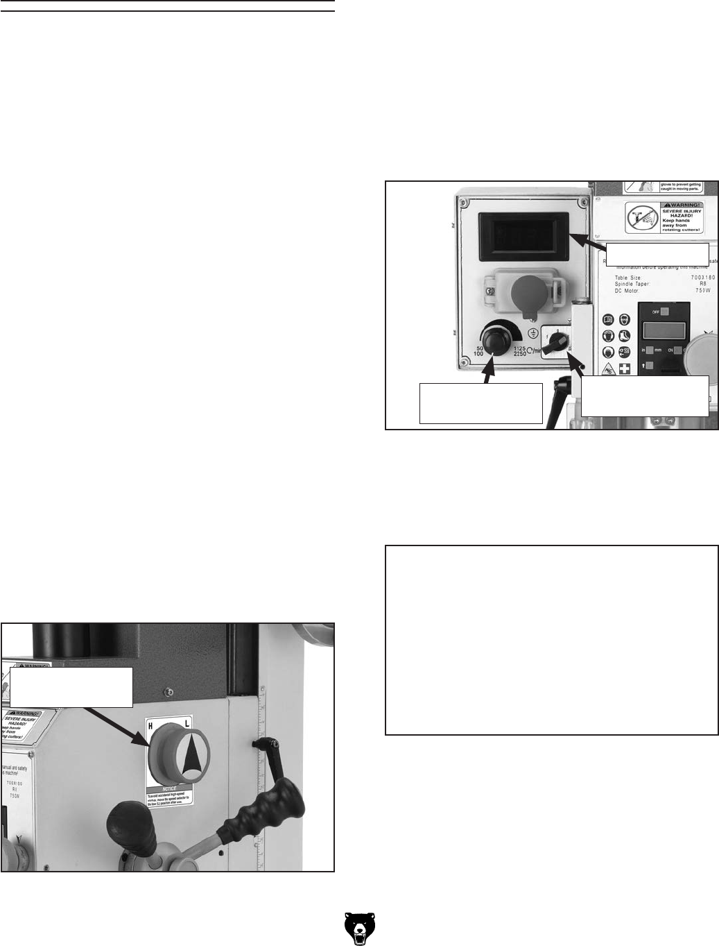
Model G0704 (Mfg. Since 0 8/11)-27-
Spindle Speed and
Direction
Setting the speed on the Model G0704 is a two
part process. The gearbox in the headstock has
two gear ranges and the motor is a variable speed
unit. Together, these two systems provide an
overall speed range of 50–2250 RPM.
When the dial is turned up all the way, the motor
draws the full amperage level. When combined
with a cutting load, the motor can overheat and
become damaged. If high speeds are needed, put
the speed range into high "H" then turn the vari-
able speed dial down, away from the maximum
position. If the maximum RPM is needed, reduce
the cutting load as much as possible and mini-
mize the operation time at these speeds.
To set the spindle speed:
1. Determine the appropriate spindle speed for
your operation. See Calculating Spindle
Speed on Page 26.
2. Select the appropriate speed range using
the speed range selector knob (Figure 25).
"H" represents the high speed range, which
is capable of spindle speeds from 100–2250
RPM. "L" represents the low range, which
is capable of spindle speeds from 50–1125
RPM.
Note: To maximize spindle torque, use the
low range.
Note: It may be necessary to rotate the
spindle by hand to get the gears to mesh
properly.
3. Make sure the work area is clear and that all
safety precautions are taken.
Figure 25. Speed selector knob.
Speed Selection
Knob
4. Turn the variable spindle speed knob to the
far left (slowest) position, then press the
green start button and use the spindle direc-
tion selection knob to choose the direction
of spindle travel and start spindle rotation
(Figure 26).
Figure 26. Spindle direction selection knob.
5. Watch the RPM readout and adjust the vari-
able spindle speed knob as needed until the
desired RPM is reached.
Spindle Direction
Selection Knob
RPM Readout
Variable Spindle
Speed Knob
NOTICE
AVOID OVERHEATING MOTOR!
DO NOT operate with variable speed dial at
full RPM for than a couple minutes or motor
overheating may occur. Instead, achieve the
same spindle speed by using the high “H”
speed range and reducing the motor RPM
by turning the variable speed dial down.
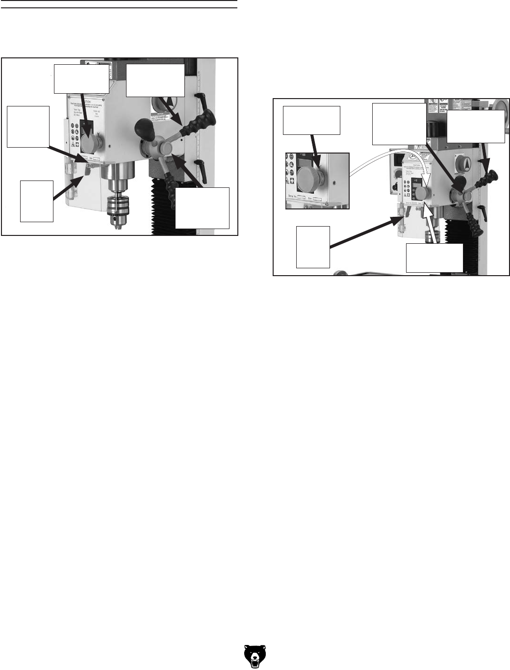
-28- Model G0704 (Mfg. Since 0 8 /11)
Changing Spindle Position Using
Fine Feed Knob
1. Unlock the quill lock lever and tighten the fine
feed lock knob.
2. Rotate the fine feed knob to lower or raise
the spindle in small increments. Observe the
scale on the knob or the digital readout to
monitor movement in thousandths of an inch
(Figure 28).
3. Tighten the quill lock lever to hold the spindle
in a particular position if you choose.
Tip: Milling with the spindle fully extended
can cause tool chatter. For maximum spindle
rigidity when milling, it is better to keep the
spindle retracted into the headstock as far
as possible with the quill lock lever tightened,
and the fine feed knob tightened.
Figure 28. Fine spindle feed controls.
Fine Feed
Scale
Fine Feed
Knob
Spindle Height
Controls
The spindle height is controlled by the quill feed
lever and the fine feed knob.
Changing Spindle Position Using
Quill Feed Levers
1. Unlock the quill lock lever and loosen the fine
feed lock knob.
2. Pull down on any of the coarse downfeed
levers to adjust the vertical position of the
spindle. Observe the spindle height scale or
digital readout to monitor movement in inches
or millimeters.
Tip: Milling with the spindle fully extended can
cause tool chatter. For maximum spindle
rigidity when milling, it is better to keep the
spindle retracted into the headstock as far
as possible with the spindle lock and the
downfeed selector knob tightened.
Quill
lock
lever
Quill Feed
Lever
Figure 27. Spindle controls.
Spindle
Height
Scale
Quill
lock
lever
Fine Feed
Knob
Quill Feed
Lever
Fine Feed
Lock
Knob
Fine Feed
Lock
Knob
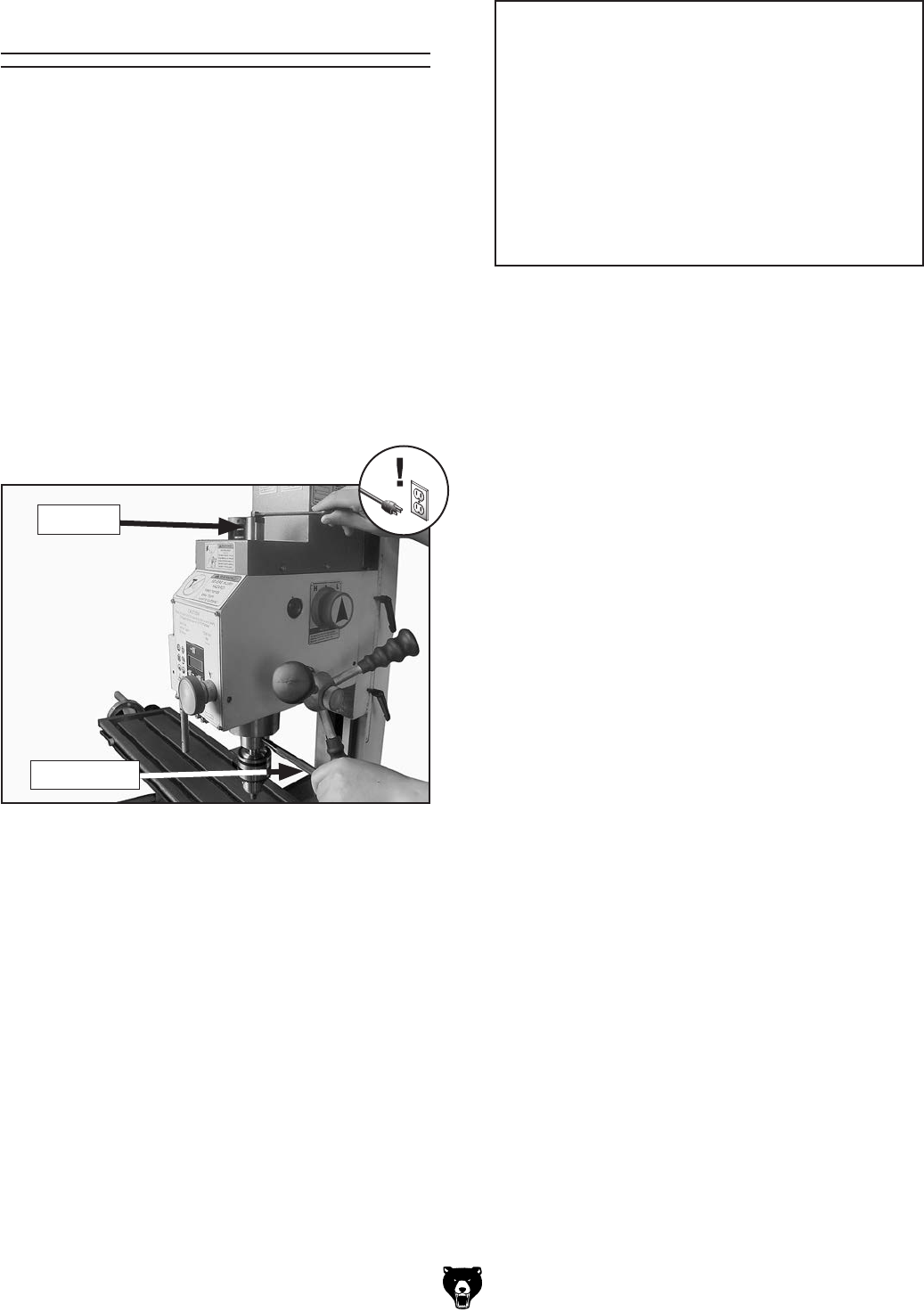
Model G0704 (Mfg. Since 0 8/11)-29-
Drill Chuck
Figure 29. Tightening the drawbar.
5. Hold the chuck with one hand and finish loos-
ening the drawbar until the chuck falls out of
the spindle.
Note: The chuck is attached to the arbor
using a B-16 taper. This attachment is con-
sidered to be semi-permanent. There should
be no need to remove the chuck from the
arbor.
4. Use the included spindle pin to prevent the
spindle from turning while you use an 8mm
wrench to loosen the drawbar 2–3 turns. DO
NOT continue loosening the drawbar without
supporting the drill chuck or it will fall from the
spindle.
To remove the chuck and arbor from the
spindle:
1. DISCONNECT MILL/DRILL FROM POWER!
2. Remove the drawbar cap.
3. Lock the quill in place with the quill lock
lever.
To install the drill chuck and arbor:
1. DISCONNECT MILL/DRILL FROM POWER!
2. Remove the drawbar cap.
3. Insert the chuck arbor into the spindle, mak-
ing sure to line up the slot in the arbor with
the pin in the spindle.
4. Thread the drawbar into the arbor until the
arbor is seated up into the spindle taper.
5. Use the included spindle pin to prevent the
spindle from turning while you use an 8mm
wrench to tighten the drawbar.
NOTICE
The Model G0704 drawbar will extract the
arbor from the spindle. Once the arbor or
collet has broken free from the spindle
taper, be sure to properly support it while
continuing to loosen the drawbar. Failure
to properly support the arbor or collet
while loosening the drawbar will result in
the arbor or collet falling out of the spindle,
causing damage to machine components.
Note: Do not overtighten the drawbar.
Overtightening makes arbor removal difficult
and will damage the arbor and threads.
6. Re-install the drawbar cap.
Drawbar
Spindle Pin

-30- Model G0704 (Mfg. Since 0 8/11)
Your Model G0704 features an R-8 spindle taper,
which gives the freedom to use standard R-8
cutting tools and collets. These optional collets
come in many sizes, typically ranging from 1⁄16" to
7⁄8" and 3mm to 20mm, and should be matched to
your cutting tool shank size.
To install the tooling:
1. DISCONNECT MILL/DRILL FROM POWER!
2. Remove the drawbar cap.
3. Carefully clean the surface of the tooling and
spindle taper. Ensure that it is free of debris
and is lightly oiled.
4. If you are using a cutting tool and collet, insert
the cutting tool into the collet, then insert the
collet up into the spindle taper, making sure
the slot in the collet lines up with the pin in the
spindle.
If you are using a cutting tool that installs
directly into the spindle, insert the tool into the
spindle taper, making sure the slot in the tool
lines up with the pin in the spindle.
5. Slide the tooling upward until it makes con-
tact with the drawbar threads.
6. Hand thread the drawbar into the tooling until
the tooling draws up into the spindle taper.
7. Use the included spindle pin to prevent the
spindle from turning while you use an 8mm
wrench to tighten the drawbar.
Note: Do not overtighten the drawbar.
Overtightening makes collet removal difficult
and will damage the drawbar threads, collet,
and the spindle taper. Keep in mind that the
taper keeps the collet and tool in place. The
drawbar simply aids in seating the taper.
Loading Tooling To remove the collet:
1. DISCONNECT MILL/DRILL FROM POWER!
2. Remove the drawbar cap.
3. Lock the quill in place with the quill lock
lever.
4. Use the included spindle pin to prevent the
spindle from turning while you use an 8mm
wrench to loosen the drawbar 2–3 turns. DO
NOT continue loosening the drawbar without
supporting the collet or it will fall from the
spindle.
LACERATION HAZARD!
Leading edges of end mills
and other cutting tools can
be very sharp. Protect your
hands with gloves or a shop
towel when handling.
5. Protect the table surface with a piece of
cardboard and hold the cutter/tool with a
shop towel to prevent it from falling out of the
collet. Continue loosening the drawbar until
the collet is freed from the spindle.
NOTICE
The Model G0704 drawbar will extract the
arbor from the spindle. Once the arbor or
collet has broken free from the spindle
taper, be sure to properly support it while
continuing to loosen the drawbar. Failure
to properly support the arbor or collet
while loosening the drawbar will result in
the arbor or collet falling out of the spindle,
causing damage to machine components.
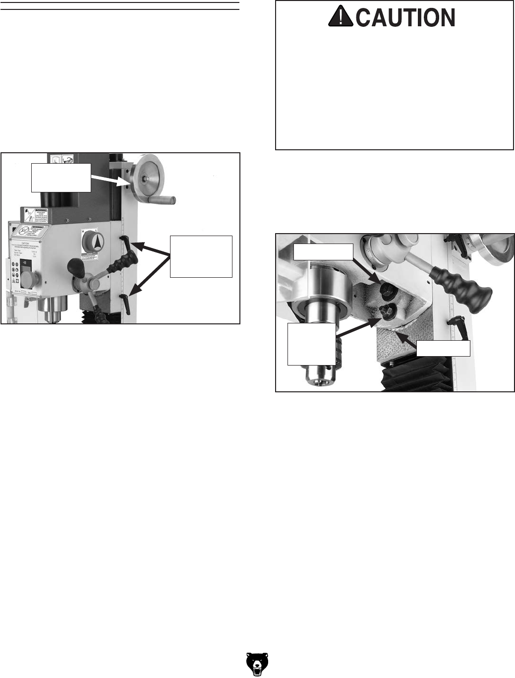
Model G0704 (Mfg. Since 0 8/11)-31-
2. Turn the vertical handwheel shown in Figure
30 to raise or lower the headstock, then lock
the vertical travel lock levers.
Note: For maximum spindle rigidity when
milling, keep the spindle retracted into the
headstock as far as possible with the quill
lock lever locked and with the fine feed lock
knob tightened.
Headstock Travel
(Z-Axis and Rotation)
Headstock height is adjustable in the vertical
Z-axis to accept large workpieces. For unique
milling operations, the headstock can be tilted
right or left between 0° and 90°.
To raise or lower the headstock:
1. Unlock the vertical travel lock levers shown in
Figure 30.
To tilt the headstock to the left or right:
1. DISCONNECT MILL/DRILL FROM POWER.
Figure 30. Headstock slide controls.
Vertical
Travel Lock
Levers
Vertical
Handwheel
Figure 31. Headstock tilt controls.
Center Bolt
Tilt Scale
Angle
Lock Nut
1 of 3
2. Support the headstock with one hand, then
using the included 17/19mm combo wrench,
loosen the headstock center bolt and three
angle lock nuts (Figure 31).
During the following steps, be aware that the
headstock is top-heavy and will swing if it is
not well supported once the center bolt and
lock nut are loosened. Always support the
headstock with one hand when loosening
these fasteners. Failure to do so may result
in unexpected movement of the headstock,
causing damage to the machine and per-
sonal injury.
3. While watching the tilt scale, rotate the head-
stock to the required angle, then retighten
the center bolt and angle lock nut to hold the
headstock in place.
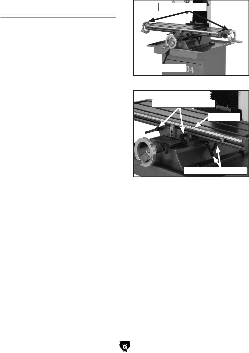
-32- Model G0704 (Mfg. Since 08 /11)
Figure 33. Table locks and scales.
Table Travel
The mill/drill table can be moved in the longitudi-
nal (X-axis) and cross (Y-axis) directions.
Longitudinal Feed
The X-axis is moved by the handwheels shown
in Figure 32 at the end of the table. These
handwheels will move the table in both directions
side-to-side. One complete revolution of either
handwheel moves the longitudinal feed 0.100".
There is also a scale on the front of the table for
use when a tight tolerance is not required. The
longitudinal feed can be locked in position by
table locks located on the front of the table (see
Figure 33).
Cross Feed
The Y-axis shown in Figure 32, is moved with the
handwheel on the front of the table base. One
complete revolution of the handwheel moves the
cross slide 0.100". The cross feed can be locked
into position by a table lock lever located on the
right side of the cross slide underneath the table
(see Figure 33).
Figure 32. Table X- and Y-axis controls.
X-Axis Scale
X-Axis Table Lock Levers
Y-Axis Table Lock Levers
X-Axis Handwheels
Y-Axis Handwheel
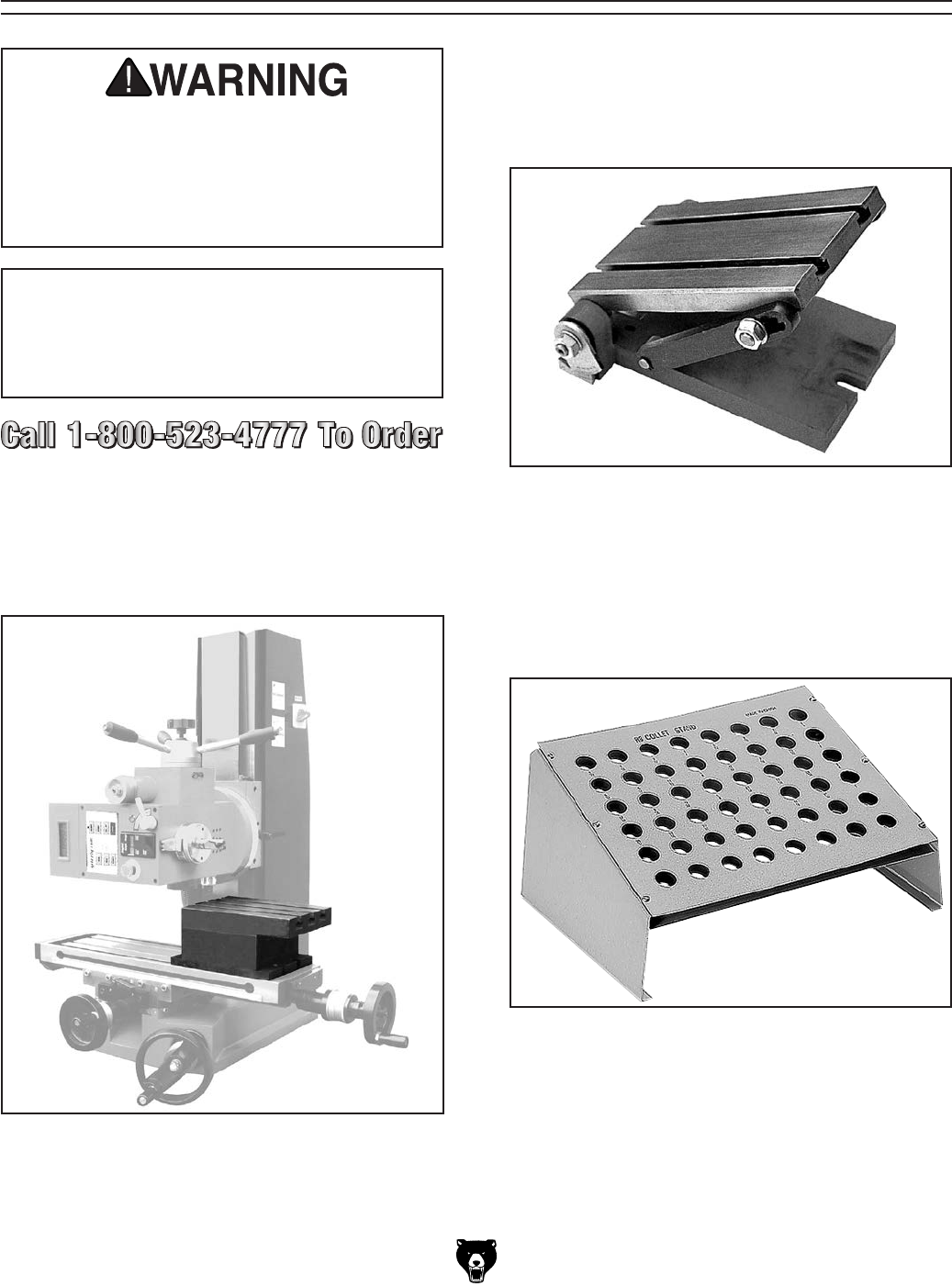
Model G0704 (Mfg. Since 0 8/11)-33-
SECTION 5: ACCESSORIES
ACCESSORIES
H8177—Worktable with Angle
Enjoy having an economical way to support your
workpiece at an array of angles. This high-quality
tilting worktable is quick and easy to setup and
use.
Figure 35. Worktable with angle.
Figure 34. Horizontal milling worktable.
H8179—Horizontal Milling Table
Take advantage of the G0704 mill/drill 90° tilting
headstock feature. Install this lifted cast-iron hori-
zontal milling table for the correct clearance when
making those side-milling operations.
H8179
Some aftermarket accessories can be
installed on this machine that could cause
it to function improperly, increasing the risk
of serious personal injury. To minimize this
risk, only install accessories recommended
for this machine by Grizzly.
NOTICE
Refer to www.grizzly.com or the newest
copy of the Grizzly Catalog for other acces-
sories available for this machine.
G5684—R-8 Vertical Collet Rack
No more loose R-8 collets laying around in your
tool box. Organize with this handy collet rack and
you won’t be looking at each one for the correct
size. Set on your bench or mount to a wall. Holds
48 collets.
Figure 36. Model G5684 Tilt Table.
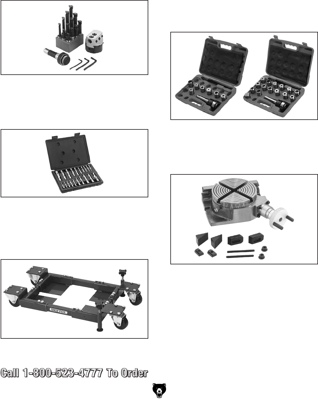
-34- Model G0704 (Mfg. Since 0 8 /11)
Figure 41. H5685 4" Rotary Table.
H5685—4" Rotary Table
The perfect rotary table for all you model makers
and those doing smaller precision work. Comes
with clamping kit.
G9322—Boring Head Combo Set
Hardened and ground adjusting screws along
with a wide base design guarantee a long life and
trouble-free use. Includes a 2" boring head, R-8
arbor with 7/16"-20 TPI, and a 12 piece 3/4" boring
bar set.
Figure 37. G9324 Boring Head Combo Set.
G9760—20-PC. 2 & 4 Flute TiN End Mill Set.
Includes these sizes and styles in two and four
flute styles: 3/16", 1/4", 5/16", 3/8", 7/16", 1/2", 9/16", 5/8",
3/8", 11/16", and 3/4".
Figure 38. G9760 20-PC End Mill Set.
Figure 39. Model G8683Z Mini Shop Fox®
Mobile Base.
G8683Z—Mini Shop Fox® Mobile Base
Don't let the little size of this one fool you. It shares
the same design concepts as its two bigger broth-
ers, giving you an amazing 600 lb. load capacity
in one small package!
H8257—Primrose Armor Plate with Moly-D
Machine and Way Oil 1 Quart
This superior machine and way lubricant prevents
stick slip and chatter due to anti-friction capa-
bilities resulting in greater precision machining
capabilities. Provides the thinnest oil film pos-
sible while effectively providing needed lubrication
and rust/corrosion protection. Adhesive/cohesive
components are added for vertical surfaces.
Resists squeeze out, running, dripping and non-
gumming.
T10067—8 Pc. R-8 Quick Change Collet Set
T10068—16 Pc. R-8 Quick Change Collet Set
These are the best collet sets we've ever carried.
They can be used in production shops and for high
precision work. Includes R-8 quick change collet
chuck, 1⁄4", 5⁄16", 3⁄8", 1⁄2", 5⁄8", 3⁄4" and 1" collets,
spanner wrench and moulded plastic case. The
16 pc. set includes everything in the 8 pc. set plus
1⁄8", 3⁄16", 7⁄16", 9⁄16", 11 ⁄16", 13 ⁄16", 7⁄8", and 15⁄16" collets.
Made in Taiwan!
Figure 40. T10067 & T10068 Collet Sets.
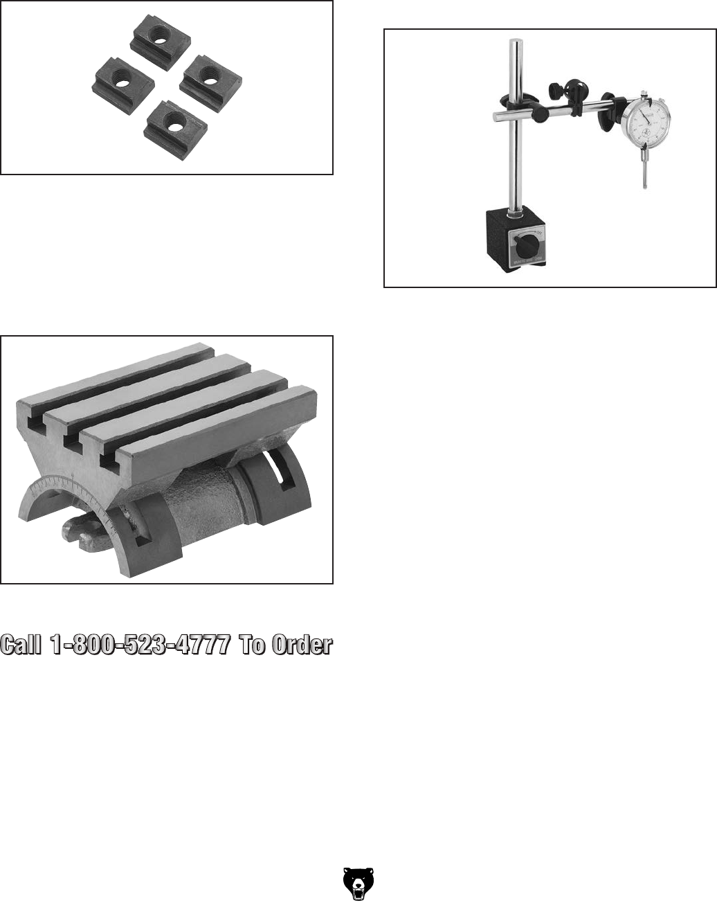
Model G0704 (Mfg. Since 0 8/11)-35-
G9512—T-Slot Nuts, 4 PK, 1/2" Slot, 3/8"-16
Heat treated steel T-Slot Nuts with black oxide
finish feature an imperfect thread in the base of
the T-nut to eliminate any danger of screwing the
clamping stud through and damaging the table
slot.
Figure 42. Model G9512 T-Slot Nuts.
G9849—Magnetic Base/Dial Indicator Combo
Precision measurements and setups have never
been so easy. Magnetic base engages with just
the turn of a switch and allows pinpoint adjust-
ment. The dial indicator features 0-1" travel and
has a resolution of 0.001". This fine set includes a
molded case for protection and convenience.
Figure 44. Model G9849 Indicator/Base Combo
G5758—Tilt Table 5" x 7"
Set your work at any angle with these sturdy tilt
tables. Heavy-duty construction includes T-slots,
two locking screws and precision base that allows
the table to tilt from -45 Degrees to +45 Degrees.
Table size: 5" x 7".
Figure 43. Model G5758 Tilt Table.
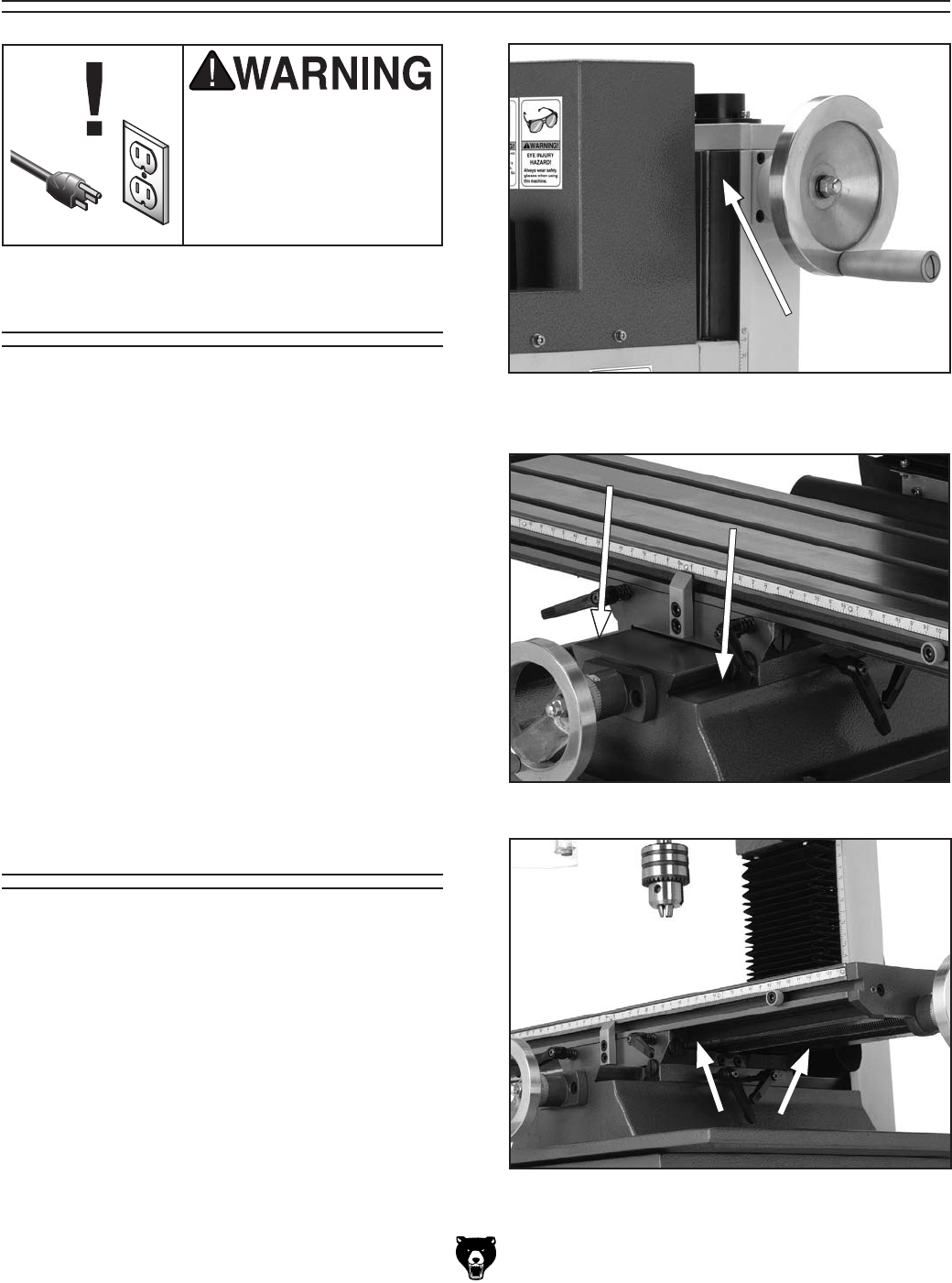
-36- Model G0704 (Mfg. Since 0 8/11)
SECTION 6: MAINTENANCE
Always disconnect power
to the machine before
performing maintenance.
Failure to do this may
result in serious person-
al injury.
For optimum performance from your machine,
follow this maintenance schedule and refer to any
specific instructions given in this section.
Daily Check:
• Make sure mill/drill is disconnected from
power when not in use.
• Check for loose mounting bolts.
• Make sure mill/drill is clean and lubricated.
• Check for worn or damaged wires.
• Check for any other unsafe condition.
Monthly Check:
• Check that gibs are adjusted properly.
Biannual Check:
• Lubricate headstock lead screw and gears.
Schedule
Regular lubrication will ensure your mill/drill per-
forms at its highest potential. Regularly wipe all
sliding surfaces with Primrose® Way Oil (Page 34)
or a light machine oil, then move the components
back and forth several times to ensure smooth
movements (Figures 45–47). Every six months,
or more often with heavy use, clean and lubricate
the leadscrews and vertical handwheel ring & pin-
ion gears, as outlined on Page 38.
Protect other unpainted cast iron surfaces with
regular applications of products like G96® Gun
Treatment, SLIPIT®, or Boeshield® T-9.
Lubrication
Figure 45. Vertical way lube location (both
sides).
Figure 46. Cross way lube locations.
Figure 47. Longitudinal way lube locations.
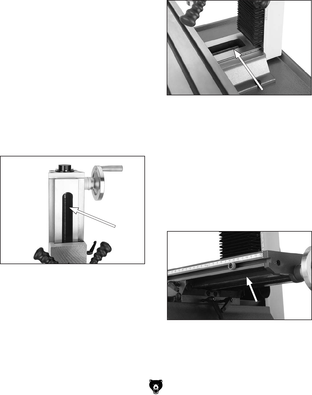
Model G0704 (Mfg. Since 0 8/11)-37-
6. Lift or remove the rubber way cover, then
use mineral spirits and a brush to clean as
much of the existing grease and debris as
possible off of the cross travel leadscrew
shown in Figure 49. Allow leadscrew to dry.
Every six months, or more frequently under heavy
use, we recommend that you clean and lubricate
the leadscrews and vertical handwheel gears with
a light machine oil and multi-purpose grease.
Tools Needed: Qty
Hex Wrench 3, 4mm .......................................... 1
Multi-Purpose Lithium Grease ........................... 1
Paint Brush for Grease Application ................... 1
Oil Bottle of 10-30w Synthetic Oil ..................... 1
Stiff-Bristled Nylon Brush for Cleaning .............. 1
Mineral Spirits ................. As needed for cleaning
Shop Rags ...................... As needed for cleaning
To lubricate the leadscrews:
1. DISCONNECT MILL/DRILL FROM POWER!
2. Lower the headstock as far as you can with-
out the spindle contacting the table surface.
3. Use mineral spirits and a brush to clean as
much of the existing grease and debris as
possible off of the vertical leadscrew shown
in Figure 48. Allow leadscrew to dry.
Figure 48. Vertical leadscrew location.
Figure 49. Cross travel leadscrew location.
Figure 50. Longitudinal leadscrew location.
4. Apply light machine oil to the exposed
leadscrew threads, then move the headstock
through its full range of motion several times
to disperse the oil along the full length of the
leadscrew.
5. Using the cross handwheel, move the table
as far forward as possible.
7. Apply light machine oil to the exposed
leadscrew threads, then move the table
through its full range of cross motion several
times to disperse the oil along the full length
of the leadscrew.
8. Using the longitudinal handwheel, move the
table as far to one side as possible.
9. From beneath the table, use mineral spirits
and a brush to clean as much of the existing
grease and debris as possible off of the longi-
tudinal travel leadscrew shown in Figure 50.
Allow the leadscrew to dry.
10. Apply light machine oil to the exposed
leadscrew threads, then move the table
through its full range of longitudinal motion
several times to disperse the oil along the full
length of the leadscrew.
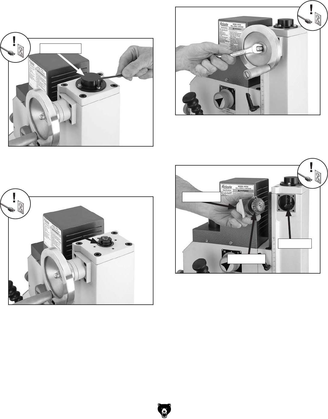
-38- Model G0704 (Mfg. Since 0 8 /11)
Figure 51. Bushing cap removal.
Figure 53. Handwheel removal.
Figure 52. Bushing oil location.
To lubricate the vertical leadscrew bushing
and ring & pinion gears:
1. DISCONNECT MILL/DRILL FROM POWER!
2. Remove the bushing cap by unthreading the
four cap screws that secure it (Figure 51).
3. Apply several drops of light machine oil to
the bushing edge, then rotate the vertical
handwheel to disperse the oil (Figure 52).
Bushing Cap
4. Replace the bushing cap.
5. Remove the acorn nut and flat washer that
secure the vertical handwheel, then remove
the handwheel (Figure 53).
6. Remove the four cap screws that secure the
handwheel shaft pillow block, then carefully
remove the assembly (Figure 54).
Figure 54. Handwheel gears.
7. Use mineral spirits and a brush and rag to
clean as much of the existing grease and
debris as possible off of the ring and pinion
gears. Allow the parts to dry.
8. Apply a liberal coat of multi-purpose grease
to the pinion gear.
9. Re-assemble the machine by reversing the
steps above.
Pinion Gear
Ring Gear
Pillow Block

Model G0704 (Mfg. Since 0 8/11)-39-
SECTION 7: SERVICE
Troubleshooting
Symptom Possible Cause Possible Solution
Machine does not
start.
1. Circuit breaker on machine tripped.
2. Plug at fault or wired incorrectly.
3. Motor wired incorrectly.
4. Wall fuse/circuit breaker is blown/tripped.
5. Wiring is open/has high resistance.
6. Machine power switch is at fault.
7. Motor is at fault.
1. Press reset button on motor junction box; reduce
load on motor to prevent overheating.
2. Ensure plug is not damaged and is wired correctly.
3. Ensure motor wiring is correct.
4. Ensure circuit size is correct and a short does not
exist. Reset breaker or replace fuse.
5. Check for broken wires or disconnected/corroded
connections; repair/replace as necessary.
6. Ensure switch is wired correctly; replace if at fault.
7. Test/repair/replace.
Machine stalls or is
overloaded.
1. Feed rate/cutting speed too fast.
2. Wrong cutter type.
3. Machine is undersized for the task or tooling
is incorrect for the task.
4. Motor connection is wired incorrectly.
5. Motor bearings are at fault.
6. Motor has overheated.
7. Motor is at fault.
1. Decrease feed rate/cutting speed.
2. Use the correct cutter for the task.
3. Use smaller or sharper tooling; reduce feed rate or
spindle speed; use cutting fluid if possible.
4. Wire motor correctly for the intended voltage.
5. Test by rotating shaft; rotational grinding/loose shaft
requires bearing replacement.
6. Clean off motor, let cool, and reduce workload.
7. Test/repair/replace motor.
Machine has
vibration or noisy
operation.
1. Motor or machine component is loose.
2. Excessive depth of cut.
3. Cutter/tooling is loose.
4. Cutter is dull or at fault.
5. Bit is chattering.
6. Machine is incorrectly mounted or sits
unevenly.
7. Motor bearings are at fault.
1. Inspect/replace stripped or damaged bolts/nuts, and
re-tighten with thread locking fluid.
2. Decrease depth of cut.
3. Make sure tooling is properly secured.
4. Replace/resharpen cutter.
5. Replace/sharpen bit; index bit to workpiece; use
appropriate feed rate and cutting RPM.
6. Tighten/replace mounting bolts in bench; relocate/
shim machine.
7. Test by rotating shaft; rotational grinding/loose shaft
requires bearing replacement.
Troubleshooting
Review the troubleshooting and procedures in this section if a problem develops with your machine. If you
need replacement parts or additional help with a procedure, call our Technical Support at (570) 546-9663.
Note: Please gather the serial number and manufacture date of your machine before calling.

-40- Model G0704 (Mfg. Since 0 8/11)
Symptom Possible Cause Possible Solution
Tool slips in collet. 1. Collet is not fully drawn up into
spindle taper.
2. Wrong size collet.
3. Debris on collet or in spindle taper.
4. Taking too big of a cut.
1. Tighten drawbar.
2. Measure tool shank diameter and match with
appropriate diameter collet.
3. Clean collet and spindle taper.
4. Lessen depth of cut and allow chips to clear.
Breaking tools or cutters. 1. Spindle speed too slow/feed rate is
too fast.
2. Cutting tool getting too hot.
3. Taking too big of a cut.
4. Spindle extended too far down.
1. Set spindle speed correctly (Page 27) or use a
slower feed rate.
2. Use coolant fluid or oil for appropriate application.
(Follow cutting fluid manufacturer's recommendation
for proper use and safety.)
3. Decrease depth of cut.
4. Fully retract spindle and lower headstock. This
increases rigidity.
Workpiece vibrates or
chatters during operation.
1. Table locks not tight.
2. Quill lock lever not tight.
3. Workpiece not securely clamped to
table or into mill vice.
4. Spindle speed is too slow /feed rate
is too fast.
5. Spindle extended too far down.
1. Tighten down table locks (Page 32).
2. Tighten quill lock lever.
3. Check that clamping is tight and sufficient for the job.
Make sure mill vice is tight to the table.
4. Set spindle speed correctly (Page 27) or use a
slower feed rate.
5. Fully retract spindle and lower headstock. This
increases rigidity.
Table is hard to move. 1. Table locks are tightened down.
2. Chips have loaded up on ways.
3. Ways are dry and need lubrication.
4. Table limit stops are interfering.
5. Gibs are too tight.
1. Make sure table locks are fully released.
2. Frequently clean away chips that load up during
milling operations.
3. Lubricate ways and handles (Page 36).
4. Check to make sure that all table limit stops are not
in the way.
5. Adjust gibs (see Page 41).
Bad surface finish. 1. Spindle speed is too slow/feed rate
is too fast.
2. Using a dull or incorrect cutting tool.
3. Wrong rotation of cutting tool.
4. Workpiece not securely clamped.
5. Spindle extended too far down.
1. Set spindle speed correctly (Page 27) or use a
slower feed rate.
2. Sharpen cutting tool or select one that better suits the
operation.
3. Check for proper cutting rotation for cutting tool.
4. Secure properly to the table.
5. Fully retract spindle and lower headstock. This
increases rigidity.
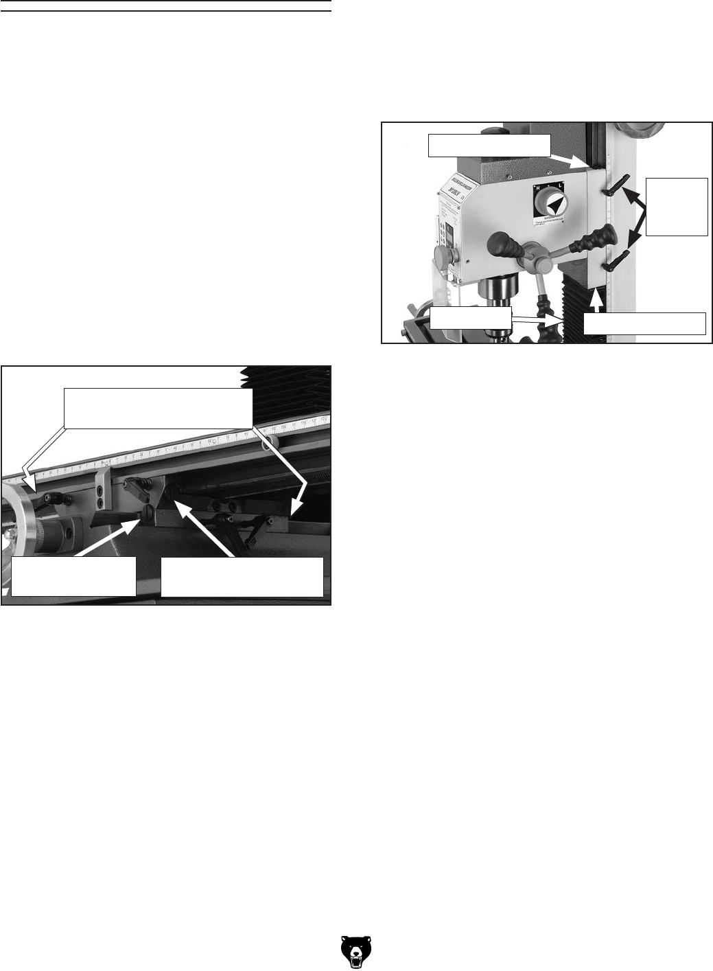
Model G0704 (Mfg. Since 0 8/11)- 41-
Gibs are wedge-shaped pieces of metal that
fill the gap between the sliding surfaces of the
machine. By adjusting the position of the gib in
its gap, you can remove any play that might exist
between the adjacent components. The gibs are
pre-adjusted at the factory but due to storage,
break-in, and usage, may require adjustment. If
movement seems too tight at first, make sure that
all the rust preventative that was shipped on the
machine is removed from the ways. Lubricate the
ways with oil, and work the table back-and-forth
several times until the movement is easier.
To adjust the table gibs:
1. DISCONNECT MILL/DRILL FROM POWER!
2. Loosen the table travel locks (Figure 55).
Gibs
Figure 55. Table gib adjustment screw locations.
To adjust the headstock gibs:
1. DISCONNECT MILL/DRILL FROM POWER!
2. Remove the two screws that secure the top
end of the way cover, pull it down to expose
the lower gib screw, then loosen the vertical
travel locks (Figure 56).
3. Loosen or tighten the front and rear gib
screws (Figure 55) in an alternating manner
to adjust the cross travel gib.
The table should slide smoothly in the cross
direction with no play or looseness. Do not
overtighten the gibs or premature slide and
gib wear will occur.
4. Lubricate the cross way and gib.
5. Repeat the process for the longitudinal way
gib using the gib adjustment screws on the
left and right sides of the table base.
3. Loosen or tighten the upper and lower gib
screws (Figure 56) in an alternating manner
to adjust the headstock gib.
The headstock should slide smoothly with no
play or looseness. Do not overtighten the gibs
or premature slide and gib wear will occur.
4. Lubricate the headstock way and gib.
5. Re-install the way cover.
Figure 56. Headstock gib adjustment.
Upper Gib Screw
Lower Gib Screw
Vertical
Travel
Locks
Cross Gib Screw
(1 of 2 shown)
Longitudinal Gib Screw
(1 of 2 shown)
Locations of
Corresponding Gib Screws
Way Cover
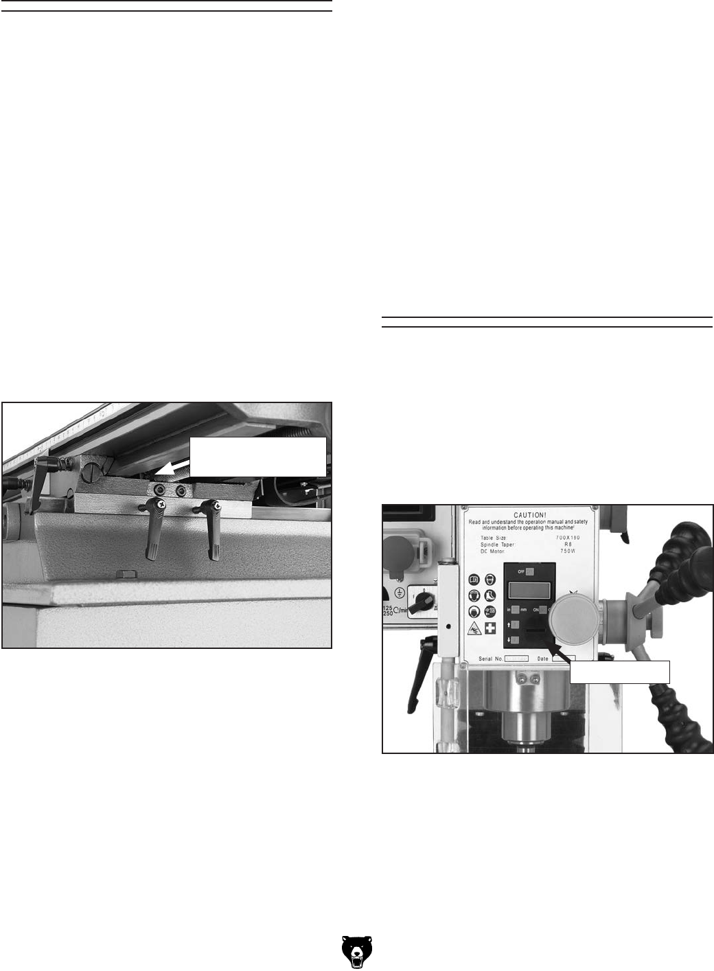
-42- Model G0704 (Mfg. Since 0 8 /11)
Figure 57. X-axis leadscrew adjusters.
Leadscrew Backlash
Digital Readout Unit
Battery Replacement
When you turn the handwheels to adjust the posi-
tion of the table, you will notice slight play (back-
lash) in the handwheel before the table begins to
move. If this play is greater than 0.008" (measured
with the dial at the base of each handwheel), then
you will need to adjust the leadscrew nuts.
To reach the adjustment screws on the leadscrew
nut, you may have to fabricate extensions for
your hex wrenches. When adjusting, make adjust-
ments in small increments. Attempting to reduce
backlash to less than 0.003" is impractical and
will add unnecessary wear to both the leadscrews
and the leadscrew nuts.
To adjust the X-axis leadscrew:
1. Locate the X-axis leadscrew nut under the
middle of the table. The head on the adjust-
ment screws face to the right (Figure 57).
To adjust the Y-axis leadscrew nut:
1. Locate the leadscrew nut underneath the
table through the hole in the base under the
rubber way cover.
2. Tighten the adjustment screws on the
leadscrew nut in the same manner as
described for the X-axis leadscrew adjust-
ment.
3. Test the adjustment by turning one of the
cross handwheels. The ideal amount of play
when properly adjusted is 0.003"–0.006".
2. Tighten the adjustment screws.
3. Test the adjustment by turning one of the
longitudinal handwheels. The ideal amount
of play when properly adjusted is 0.003"–
0.006".
Figure 58. Battery replacement.
Battery Cover
If the digital readout unit stops functioning, the
battery must be replaced.
To replace the digital readout unit battery:
1. Use a wide (#3) standard screwdriver or the
edge of a coin to remove the battery cover
(Figure 58).
2. Remove the old battery, dispose of it accord-
ing to state and federal regulations, then
replace it with a new one.
3. Replace the battery cover.
Location of
Adjustment Screws
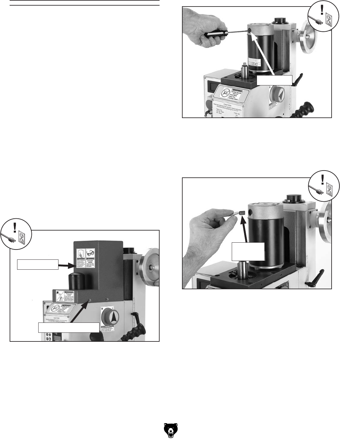
Model G0704 (Mfg. Since 0 8/11)-43-
Motor Service
The bearings inside the motor are shielded and
lubricated for the life of the bearing and require no
routine maintenance.
This motor is equipped with long life carbon
brushes. Brush life expectancy is affected by
motor loading. Heavy motor loading will result in
reduced brush life. If you notice a loss in power or
if the motor becomes excessively noisy, inspect
the brushes. If the brushes are worn down to 1⁄4''
(6mm) or less, it is time to replace them. When
checking brushes, be sure to return each brush to
the same hole in the same direction that it came
from. When replacing old brushes, replace both
brushes at the same time.
Tools Needed: Qty
Hex Wrench 3mm .............................................. 1
Standard Screwdriver #2 ................................... 1
To inspect and replace the motor brushes:
1. DISCONNECT MILL/DRILL FROM POWER!
2. Un-install the motor cover by removing the
four cap screws that secure it (Figure 59).
Figure 59. Removing motor cover.
Motor Cover
Cap Screw (1 of 4)
3. Unscrew one of the brush caps to expose the
brush assembly (Figure 60).
Figure 60. Removing brush cap.
Figure 61. Installing new brush assembly.
4. Remove the old brush assembly. If the brush
is worn down to less than 1⁄4'' (6mm) then
replace it with a new one. Otherwise re-install
the brush (Figure 61).
5. Replace the brush cap to secure the brush in
place.
6. Repeat for second brush assembly on the
other side of the motor.
Brush Cap
Brush
Assembly

-44- Model G0704 (Mfg. Since 0 8/11)
SHOCK HAZARD. Working on wiring that is con-
nected to a power source is extremely dangerous.
Touching electrified parts will result in personal
injury including but not limited to severe burns,
electrocution, or death. Disconnect the power
from the machine before servicing electrical com-
ponents!
MODIFICATIONS. Modifying the wiring beyond
what is shown in the diagram may lead to unpre-
dictable results, including serious injury or fire.
This includes the installation of unapproved after-
market parts.
WIRE CONNECTIONS. All connections must
be tight to prevent wires from loosening during
machine operation. Double-check all wires dis-
connected or connected during any wiring task to
ensure tight connections.
CIRCUIT REQUIREMENTS. You MUST follow
the requirements at the beginning of this man-
ual when connecting your machine to a power
source.
WIRE/COMPONENT DAMAGE. Damaged wires
or components increase the risk of serious per-
sonal injury, fire, or machine damage. If you notice
that any wires or components are damaged while
performing a wiring task, replace those wires or
components.
MOTOR WIRING. The motor wiring shown in
these diagrams is current at the time of printing
but may not match your machine. If you find this
to be the case, use the wiring diagram inside the
motor junction box.
CAPACITORS/INVERTERS. Some capacitors
and power inverters store an electrical charge for
up to 10 minutes after being disconnected from
the power source. To reduce the risk of being
shocked, wait at least this long before working on
capacitors.
EXPERIENCING DIFFICULTIES. If you are expe-
riencing difficulties understanding the information
included in this section, contact our Technical
Support at (570) 546-9663.
Wiring Safety Instructions
The photos and diagrams
included in this section are
best viewed in color. You
can view these pages in
color at www.grizzly.com.
These pages are current at the time of printing. However, in the spirit of improvement, we may make chang-
es to the electrical systems of future machines. Compare the manufacture date of your machine to the one
stated in this manual, and study this section carefully.
If there are differences between your machine and what is shown in this section, call Technical Support at
(570) 546-9663 for assistance BEFORE making any changes to the wiring on your machine. An updated
wiring diagram may be available. Note: Please gather the serial
number and manufacture date of your
machine before calling. This information can be found on the main machine label.
SECTION 8: WIRING
machine
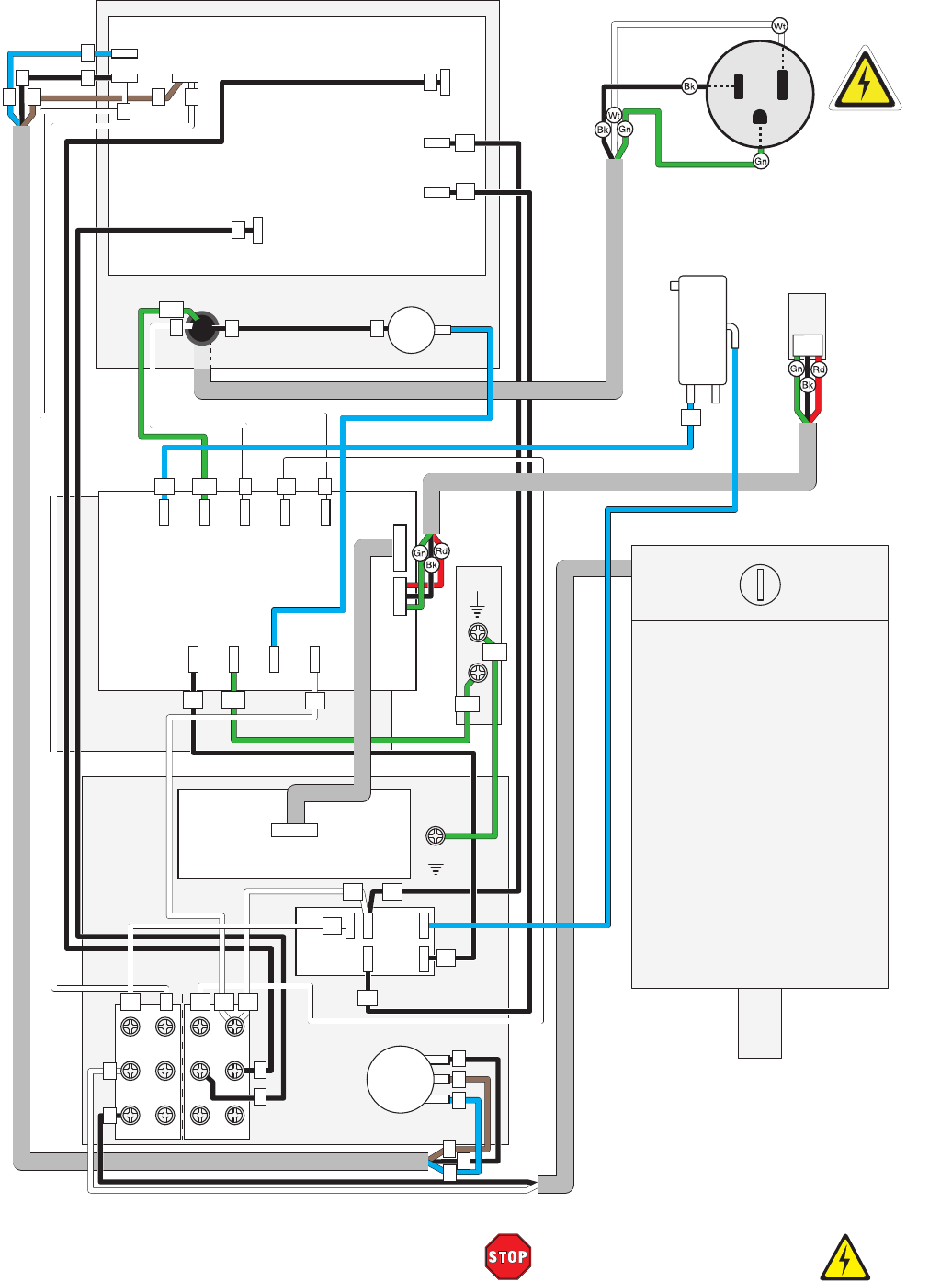
Model G0704 (Mfg. Since 08 /11)-45-
READ ELECTRICAL SAFETY
ON PAGE 44!
Wiring Diagram
GND
GND
1
1
2
2
4
6
2
1
7
3
3
11
122 2 5
N
NL
L
7
5
10
10
14
13
13
24
24 24
PE
PE PE
PE
L1
L1
24
24
11
11
3
3
14
24
P3
P1 P2 A1
A1
9
5
1
11
7
3
12
8
4
10
6
2
24
14
23
13
L1
L2
A
Circuit Board
Fuse Holder
Guard
Limit Switch
Spindle
RPM Sensor
Circuit Board
RPM Display
Spindle Direction Knob
Spindle Speed Knob
On/off Switch
IN
OUT N E L V
N E L B A
Neutral
Hot
Ground
110 VAC
5-15 Plug
PE
Motor
110V
1HP
93ZYT-008
750W
60Hz
Motor
Brushes
10A
See Figure 62
See Figure 63
See Figure 65
See Figure 64
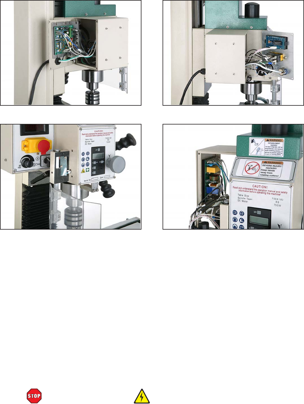
-46- Model G0704 (Mfg. Since 0 8/11)
READ ELECTRICAL SAFETY
ON PAGE 44!
Electrical Components
Figure 62. Rear panel. Figure 64. Control panel wiring.
Figure 63. Chip guard limit switch. Figure 65. Side panel.
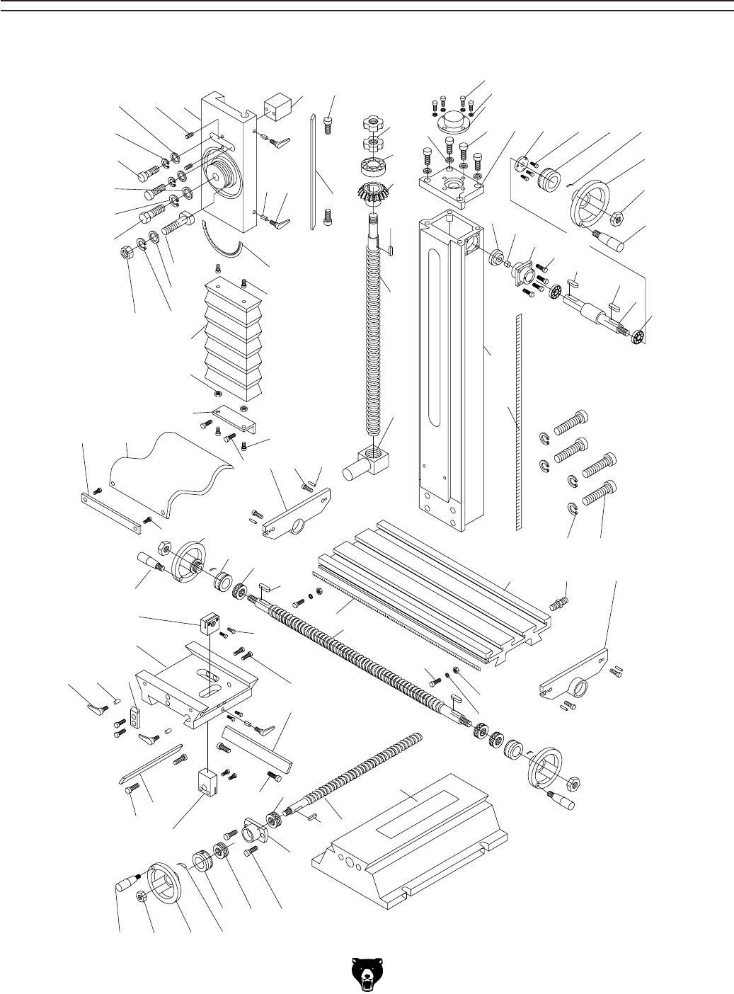
Model G0704 (Mfg. Since 0 8/11)-47-
2
3
3
4
5
6
7
8
9
10
11
20
21
22
52
5859
60
44
64
65
61
63
62
76
75
74
51
60
60
44
59
71
70
16
16
72
73
57
66
67
68
6914
15
39
58
40
57
51
19
19
19
50
2324
12
1
49
48
30
29
28
27
26
25
16
13
14 15 17
18
19
31
31-1
32
33
47
46
34 35 36 37 39
38
40
41
45 3644 44
43
42
7 77
54 55 56
Column Breakdown
SECTION 9: PARTS

-48- Model G0704 (Mfg. Since 0 8 /11)
Column Parts List
REF PART # DESCRIPTION REF PART # DESCRIPTION
1 P0704001 Z-AXIS SLIDE 39 P0704039 SPRING PIECE
2 P0704002 SET SCREW M6-1 X 16 40 P0704040 HEX NUT M8-1.25
3 P0704003 FLAT WASHER 8MM 41 P0704041 Z-AXIS HANDWHEEL HANDLE M6-1 X 10
4 P0704004 LOCK WASHER 8MM 42 P0704042 BALL BEARING 6001ZZ
5 P0704005 CAP SCREW M8-1.25 X 25 43 P0704043 Z-AXIS HANDWHEEL SHAFT
6 P0704006 FLAT WASHER 12MM 44 P0704044 KEY 4 X 4 X 12
7 P0704007 LOCK WASHER 12MM 45 P0704045 PILLOW BLOCK
8 P0704008 CAP SCREW M12-1.75 X 40 46 P0704046 SPACER
9 P0704009 T-BOLT M10-1.5 47 P0704047 PINION GEAR
10 P0704010 FLAT WASHER 10MM 48 P0704048 COLUMN
11 P0704011 LOCK WASHER 10MM 49 P0704049 Z-AXIS SCALE
12 P0704012 HEX NUT M10-1.5 50 P0704050 THREADED SLEEVE M6-1 X 16
13 P0704013 SLIDE ALIGNMENT BLOCK 51 P0704051 CAP SCREW M6-1 X 14
14 P0704014 LOCK PLUNGER, BRASS 52 P0704052 X-AXIS LEADSCREW BRACKET (LH)
15 P0704015 ADJUSTABLE HANDLE M8-1.25 X 20 54 P0704054 TABLE
16 P0704016 GIB ADJUSTMENT SCREW 55 P0704055 COOLANT HOSE FITTING
17 P0704017 Z-AXIS GIB 56 P0704056 X-AXIS LEADSCREW BRACKET (RH)
18 P0704018 HEADSTOCK ANGLE SCALE 57 P0704057 TABLE HANDWHEEL HANDLE M6-1 X 10
19 P0704019 CAP SCREW M5-.8 X 10 58 P0704058 TABLE HANDWHEEL
20 P0704020 Z-AXIS WAY COVER 59 P0704059 TABLE GRADUATED DIAL
21 P0704021 HEX NUT M5-.8 60 P0704060 THRUST BEARING 51200
22 P0704022 Z-AXIS WAY COVER BRACKET 61 P0704061 CAP SCREW M6-1 X 10
23 P0704023 Y-AXIS WAY COVER 62 P0704062 LIMIT STOP
24 P0704024 Y-AXIS WAY COVER BRACKET 63 P0704063 T-NUT M6-1
25 P0704025 Z-AXIS LEADSCREW LOCK NUT 64 P0704064 X-AXIS SCALE
26 P0704026 THRUST BEARING 51203 65 P0704065 X-AXIS LEADSCREW
27 P0704027 BEVEL GEAR 66 P0704066 X-AXIS LEADSCREW NUT
28 P0704028 KEY 4 X 4 X 16 67 P0704067 CAP SCREW M4-.7 X 20
29 P0704029 Z-AXIS LEADSCREW 68 P0704068 SADDLE
30 P0704030 Z-AXIS LEADSCREW NUT 69 P0704069 TABLE STOP BLOCK
31 P0704031 CAP SCREW M5-.8 X 12 70 P0704070 Y-AXIS GIB
31-1 P0704031-1 FLAT WASHER 5MM 71 P0704071 Y-AXIS LEADSCREW NUT
32 P0704032 BEARING COVER 72 P0704072 X-AXIS GIB
33 P0704033 CAP SCREW M8-1.25 X 20 73 P0704073 CAP SCREW M6-1 X 25
34 P0704034 COLUMN TOP PLATE 74 P0704074 X-AXIS BEARING HOUSING
35 P0704035 COLLAR FLANGE 75 P0704075 X-AXIS LEADSCREW
36 P0704036 CAP SCREW M5-.8 X 12 76 P0704076 BASE
37 P0704037 Z-AXIS GRADUATED DIAL 77 P0704077 CAP SCREW M12-1.75 X 90
38 P0704038 Z-AXIS HANDWHEEL
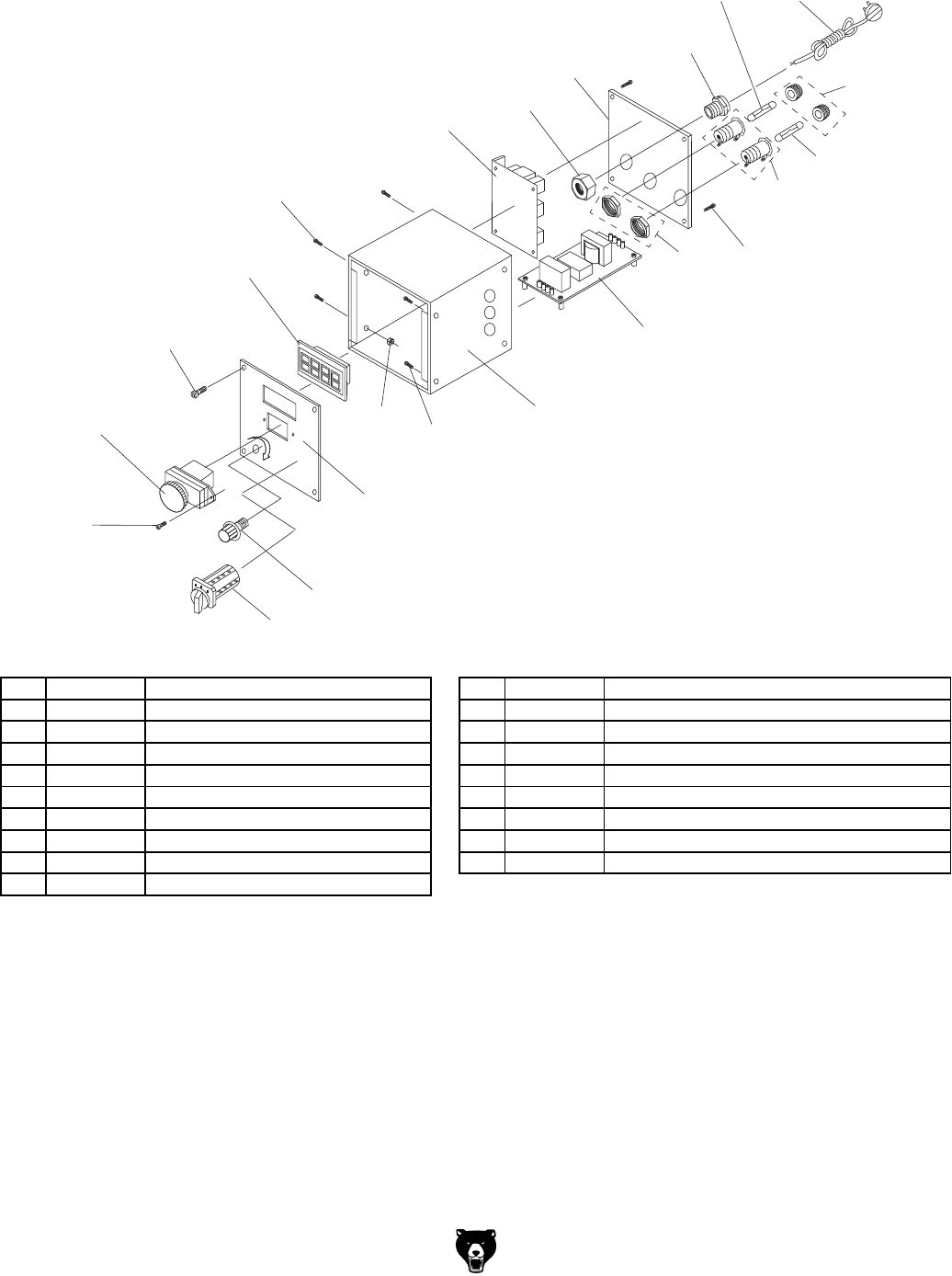
Model G0704 (Mfg. Since 0 8/11)-49-
83
84
79
85
89
88
92V2
96
86
91
91
91
81
86
87
80
80-1
78
94
90
94
93
95
Electrical Box Breakdown & Parts List
REF PART # DESCRIPTION REF PART # DESCRIPTION
78 P0704078 CIRCUIT BOARD JD-014 5WR02J 88 P0704088 ELECTRICAL BOX
79 P0704079 SPINDLE SPEED KNOB WX14-12 89 P0704089 CAP SCREW M5-.8 X 8
80 P0704080 CAP SCREW M3-.5 X 16 90 P0704090 ELECTRICAL BOX REAR COVER
80-1 P0704080-1 HEX NUT M3-.5 91 P0704091 FUSE HOLDER
81 P0704081 CIRCUIT BOARD CESX 1101-28 92V2 P0704092V2 FUSE 15A 250V FAST-ACTING GLASS V2.01.11
83 P0704083 ON/OFF SWITCH KEDU KJD-178/120V 93 P0704093 POWER CORD 18G 3W 72" 5-15
84 P0704084 CAP SCREW M4-.7 X 10 94 P0704094 STRAIN RELIEF M20 X 1.5 TYPE-3
85 P0704085 CONTROL PANEL PLATE 95 P0704095 FWD/REV SWITCH KEDU EN61058
86 P0704086 CAP SCREW M4-.7 X 6 96 P0704096 FUSE 10A 250V FAST-ACTING GLASS
87 P0704087 RPM DIGITIAL DISPLAY ZD-SX-THL
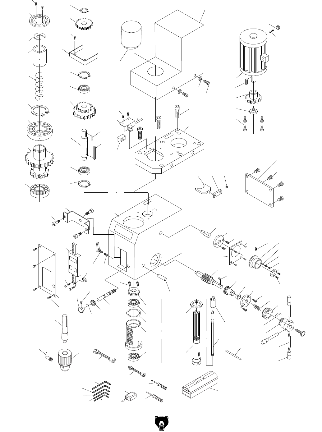
-50- Model G0704 (Mfg. Since 0 8/11)
206-2
206-1
201
202
225
226
225-2
225-1
208
209
209-2
209-1
210
211
212
213
211
210
207
206
205
204
203
219
220V2
215
214
240
239
228
229
230
231
221V2
221-1V2
221-2V2
222
223
224
227
216 217 218
254
247
251
248
250
249
296
246V2
246-1
265
264
263262
261
260
259
258
257
256
255
255-1
243
243
293
294
295
242 241 232
276
233 235
252
236 237
244
245
234
275 274
266
273
272 271
270
269
268
267
276
240
246-2
292
238
234-1
234-2
401
402
403
404
405
406
407 408
409
411
410
Headstock Breakdown

Model G0704 (Mfg. Since 0 8/11)-51-
REF PART # DESCRIPTION REF PART # DESCRIPTION
201 P0704201 QUILL RETAINING CLIP 243 P0704243 SPRING PIECE
202 P0704202 BUSHING 244 P0704244 FINE DOWNFEED GRADUATED DIAL
203 P0704203 COMPRESSION SPRING 245 P0704245 WORM SHAFT
204 P0704204 EXT RETAINING RING 45MM 246V2 P0704246 SPINDLE R8 V2.08.11
205 P0704205 BALL BEARING 6209ZZ 246-1 P0704246-1 DRAWBAR 7/16-20 x 9-11/16
206 P0704206 COMBO GEAR 60/70T 246-2 P0704246-2 DRAWBAR RETAINER CAP
206-1 P0704206-1 SPINDLE RING 16MM 247 P0704247 SPINDLE RING
206-2 P0704206-2 CAP SCREW M3-.5 X 8 248 P0704248 TAPERED ROLLER BEARING 32005
207 P0704207 ANGULAR CONTACT BEARING 7007-2RS 249 P0704249 QUILL
208 P0704208 EXT RETAINING RING 15MM 250 P0704250 QUILL SEAL, RUBBER (UPPER)
209 P0704209 GEAR 37T 251 P0704251 PRELOAD ADJUSTER NUT
209-1 P0704209-1 GEAR GUARD 252 P0704252 ADJUSTER SCREW M5-.8 X 10
209-2 P0704209-2 CAP SCREW M3-.5 X 6 254 P0704254 DOWEL PIN 6 X 30
210 P0704210 EXT RETAINING RING 32MM 255 P0704255 DOWNFEED LEVER M10-1.5 X 14
211 P0704211 BALL BEARING 6002ZZ 255-1 P0704255-1 DOWNFEED LEVER GRIP M10-1.5
212 P0704212 COMBO GEAR 42/62T 256 P0704256 KNOB BOLT M8-1.25 X 30
213 P0704213 SHAFT 257 P0704257 COARSE DOWNFEED HUB
214 P0704214 KEY 5 X 5 X 50 258 P0704258 DOWNFEED GRADUATED DIAL
215 P0704215 KEY 5 X 5 X 12 259 P0704259 COMPRESSION SPRING
216 P0704216 FORK 260 P0704260 CAP SCREW M4-.7 X 40
217 P0704217 FORK ARM 261 P0704261 DOWNFEED FLANGE
218 P0704218 SET SCREW M5-.8 X 8 262 P0704262 BUSHING
219 P0704219 DRAWBAR CAP 263 P0704263 WORM GEAR
220V2 P0704220V2 MOTOR COVER V2.11.12 264 P0704264 KEY 4 X 4 X 12
221V2 P0704221V2 MOTOR 1HP 110V 1-PH V2.11.12 265 P0704265 GEAR SHAFT 16T
221-1V2 P0704221-1V2 CARBON BRUSH 1-PC V2.11-12 266 P0704266 RIVET 2 X 5MM NAMEPLATE, STEEL
221-2V2 P0704221-2V2 CARBON BRUSH CAP 1-PC V2.11.12 267 P0704267 HI/LO INDICATOR PLATE
222 P0704222 FLAT WASHER 4MM 268 P0704268 SET SCREW M8-1.25 X 8
223 P0704223 CAP SCREW M4-.7 X 8 269 P0704269 COMPRESSION SPRING
224 P0704224 CAP SCREW M6-1 X 14 270 P0704270 STEEL BALL 6.5MM
225 P0704225 SPEED SENSOR BRACKET 271 P0704271 HI/LO HANDWHEEL
225-1 P0704225-1 SPEED SENSOR CORD 272 P0704272 SET SCREW M5-.8 X 16
225-2 P0704225-2 CAP SCREW M3-.5 X 6 273 P0704273 SPEED KNOB PLATE
226 P0704226 SPEED SENSOR 274 P0704274 FORK SHAFT FLANGE
227 P0704227 MOTOR MOUNT 275 P0704275 FORK SHAFT
228 P0704228 CAP SCREW M5-.8 X 12 276 P0704276 CAP SCREW M3-.5 X 16
229 P0704229 MOTOR GEAR RING 292 P0704292 SPINDLE PIN
230 P0704230 GEAR 20T 293 P0704293 DRILL CHUCK ARBOR R8 X B16
231 P0704231 KEY 4 X 4 X 6 294 P0704294 DRILL CHUCK B16 3-16MM
232 P0704232 SET SCREW M5-.8 X 6 295 P0704295 CHUCK KEY 1/4" STD 11T SD-3/4"
233 P0704233 CAP SCREW M3-.5 X 6 296 P0704296 TAPERED ROLLER BEARING 32007
234 P0704234 Z-AXIS DRO ASSEMBLY 401 P0704401 HEX WRENCH 6MM
234-1 P0704234-1 Z-AXIS DRO BRACKET 402 P0704402 HEX WRENCH 5MM
234-2 P0704234-2 CAP SCREW M4-.7 X 10 403 P0704403 HEX WRENCH 4MM
235 P0704235 Z-AXIS DRO SLIDE MOUNT 404 P0704404 HEX WRENCH 3MM
236 P0704236 ADJUSTABLE HANDLE M8-1.25 X 20 405 P0704405 HEX WRENCH 2MM
237 P0704237 LOCK PLUNGER, BRASS 406 P0704406 WRENCH 8 X 10MM OPEN-ENDS
238 P0704238 HEADSTOCK CASTING 407 P0704407 WRENCH 17 X 19MM OPEN-ENDS
239 P0704239 HEADSTOCK REAR COVER 408 P0704408 SCREWDRIVER FLAT #2
240 P0704240 CAP SCREW M4-.7 X 8 409 P0704409 SCREWDRIVER PHILLIPS #2
241 P0704241 FINE FEED KNOB 410 P0704410 BOTTLE FOR OIL
242 P0704242 HEADSTOCK FRONT COVER 411 P0704411 TOOLBOX
Headstock Parts List
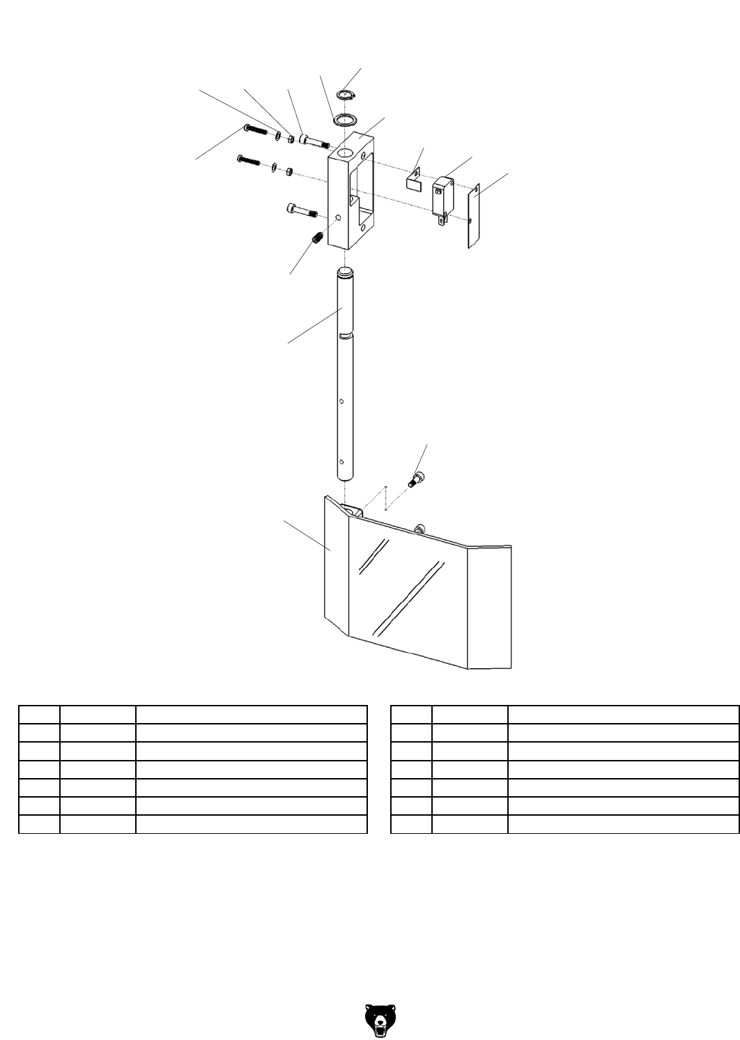
-52- Model G0704 (Mfg. Since 0 8/11)
290
277 278 279
280
281
282
283 284
285
286
287
288
289
Chip Guard Breakdown & Parts List
REF PART # DESCRIPTION REF PART # DESCRIPTION
277 P0704277 FLAT WASHER 3MM 284 P0704284 LIMIT SWITCH DATER KW1-103
278 P0704278 HEX NUT M3-.5 285 P0704285 PROTECTIVE PAPER
279 P0704279 CAP SCREW M4-.7 X 20 286 P0704286 SET SCREW M5-.8 X 10
280 P0704280 EXT RETAINING RING 12MM 287 P0704287 CHIP GUARD POST
281 P0704281 WAVY WASHER 20MM 288 P0704288 CHIP GUARD
282 P0704282 GUARD MOUNTING BLOCK 289 P0704289 CAP SCREW M4-.7 X 18
283 P0704283 SPACER, COPPER 290 P0704290 CAP SCREW M3-.5 X 16
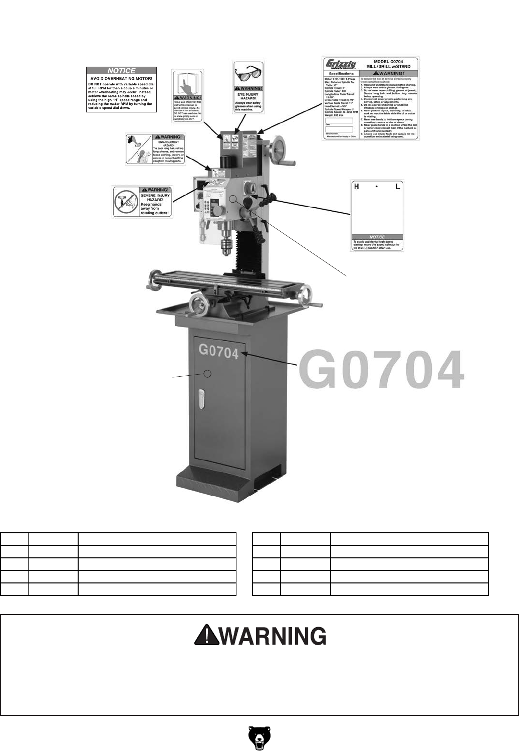
Model G0704 (Mfg. Since 0 8/11)-53-
Safety labels warn about machine hazards and ways to prevent injury. The owner of this machine
MUST maintain the original location and readability of the labels on the machine. If any label is
removed or becomes unreadable, REPLACE that label before using the machine again. Contact
Grizzly at (800) 523-4777 or www.grizzly.com to order new labels.
301
310 302 303
304
305
306
307
308
309
REF PART # DESCRIPTION REF PART # DESCRIPTION
301 P0704301 READ MANUAL LABEL 306 P0704306 MODEL NUMBER LABEL
302 P0704302 SAFETY GLASSES LABEL 307 P0704307 GREEN TOUCH-UP PAINT
303 P0704303 MACHINE ID LABEL 308 P0704308 CUTTER WARNING LABEL
304 P0704304 HIGH/LOW SPEED LABEL 309 P0704309 ENTANGLEMENT LABEL
305 P0704305 PUTTY TOUCH-UP PAINT 310 P0704310 AVOID OVERHEATING LABEL
Labels Breakdown & Parts List

-54- Model G0704 (Mfg. Since 0 8 /11)
NOTES

CUT ALONG DOTTED LINE
Name _____________________________________________________________________________
Street _____________________________________________________________________________
City _______________________ State _________________________ Zip _____________________
Phone # ____________________ Email _________________________________________________
Model # ____________________ Order # _______________________ Serial # __________________
WARRANTY CARD
The following information is given on a voluntary basis. It will be used for marketing purposes to help us develop
better products and services. Of course, all information is strictly confidential.
1. How did you learn about us?
____ Advertisement ____ Friend ____ Catalog
____ Card Deck ____ Website ____ Other:
2. Which of the following magazines do you subscribe to?
3. What is your annual household income?
____ $20,000-$29,000 ____ $30,000-$39,000 ____ $40,000-$49,000
____ $50,000-$59,000 ____ $60,000-$69,000 ____ $70,000+
4. What is your age group?
____ 20-29 ____ 30-39 ____ 40-49
____ 50-59 ____ 60-69 ____ 70+
5. How long have you been a woodworker/metalworker?
____ 0-2 Years ____ 2-8 Years ____ 8-20 Years ____20+ Years
6. How many of your machines or tools are Grizzly?
____ 0-2 ____ 3-5 ____ 6-9 ____10+
7. Do you think your machine represents a good value? _____Yes _____No
8. Would you recommend Grizzly Industrial to a friend? _____Yes _____No
9. Would you allow us to use your name as a reference for Grizzly customers in your area?
Note: We never use names more than 3 times. _____Yes _____No
10. Comments: _____________________________________________________________________
_________________________________________________________________________________
_________________________________________________________________________________
_________________________________________________________________________________
____ Cabinetmaker & FDM
____ Family Handyman
____ Hand Loader
____ Handy
____ Home Shop Machinist
____ Journal of Light Cont.
____ Live Steam
____ Model Airplane News
____ Old House Journal
____ Popular Mechanics
____ Popular Science
____ Popular Woodworking
____ Precision Shooter
____ Projects in Metal
____ RC Modeler
____ Rie
____ Shop Notes
____ Shotgun News
____ Today’s Homeowner
____ Wood
____ Wooden Boat
____ Woodshop News
____ Woodsmith
____ Woodwork
____ Woodworker West
____ Woodworker’s Journal
____ Other:

TAPE ALONG EDGES--PLEASE DO NOT STAPLE
FOLD ALONG DOTTED LINE
FOLD ALONG DOTTED LINE
GRIZZLY INDUSTRIAL, INC.
P.O. BOX 2069
BELLINGHAM, WA 98227-2069
Place
Stamp
Here
Name_______________________________
Street_______________________________
City______________State______Zip______
Send a Grizzly Catalog to a friend:

WARRANTY AND RETURNS
Grizzly Industrial, Inc. warrants every product it sells for a period of 1 year to the original purchaser from
the date of purchase. This warranty does not apply to defects due directly or indirectly to misuse, abuse,
negligence, accidents, repairs or alterations or lack of maintenance. This is Grizzly’s sole written warranty
and any and all warranties that may be implied by law, including any merchantability or fitness, for any par-
ticular purpose, are hereby limited to the duration of this written warranty. We do not warrant or represent
that the merchandise complies with the provisions of any law or acts unless the manufacturer so warrants.
In no event shall Grizzly’s liability under this warranty exceed the purchase price paid for the product and
any legal actions brought against Grizzly shall be tried in the State of Washington, County of Whatcom.
We shall in no event be liable for death, injuries to persons or property or for incidental, contingent, special,
or consequential damages arising from the use of our products.
To take advantage of this warranty, contact us by mail or phone and give us all the details. We will then
issue you a “Return Number,’’ which must be clearly posted on the outside as well as the inside of the
carton. We will not accept any item back without this number. Proof of purchase must accompany the
merchandise.
The manufacturers reserve the right to change specifications at any time because they constantly strive to
achieve better quality equipment. We make every effort to ensure that our products meet high quality and
durability standards and we hope you never need to use this warranty.
Please feel free to write or call us if you have any questions about the machine or the manual.
Thank you again for your business and continued support. We hope to serve you again soon.
WARRANTY AND RETURNS