Grizzly G0779 User Manual 6a382c6f 3d33 4eb1 B2f8 F240f6d11101
User Manual: grizzly g0779 Grizzly Drill G0779 User Guide |
Open the PDF directly: View PDF ![]() .
.
Page Count: 52

MODEL G0779
HEAVY-DUTY FLOOR MODEL
GEARHEAD DRILL PRESS
OWNER'S MANUAL
(For models manufactured since 09/14)
COPYRIGHT © MAY, 2015 BY GRIZZLY INDUSTRIAL, INC.
WARNING: NO PORTION OF THIS MANUAL MAY BE REPRODUCED IN ANY SHAPE
OR FORM WITHOUT THE WRITTEN APPROVAL OF GRIZZLY INDUSTRIAL, INC.
#WK17370 PRINTED IN CHINA V1.05.15

This manual provides critical safety instructions on the proper setup,
operation, maintenance, and service of this machine/tool. Save this
document, refer to it often, and use it to instruct other operators.
Failure to read, understand and follow the instructions in this manual
may result in fire or serious personal injury—including amputation,
electrocution, or death.
The owner of this machine/tool is solely responsible for its safe use.
This responsibility includes but is not limited to proper installation in
a safe environment, personnel training and usage authorization,
proper inspection and maintenance, manual availability and compre-
hension, application of safety devices, cutting/sanding/grinding tool
integrity, and the usage of personal protective equipment.
The manufacturer will not be held liable for injury or property damage
from negligence, improper training, machine modifications or misuse.
Some dust created by power sanding, sawing, grinding, drilling, and
other construction activities contains chemicals known to the State
of California to cause cancer, birth defects or other reproductive
harm. Some examples of these chemicals are:
• Lead from lead-based paints.
• Crystalline silica from bricks, cement and other masonry products.
• Arsenic and chromium from chemically-treated lumber.
Your risk from these exposures varies, depending on how often you
do this type of work. To reduce your exposure to these chemicals:
Work in a well ventilated area, and work with approved safety equip-
ment, such as those dust masks that are specially designed to filter
out microscopic particles.

Model G0779 (Mfd. Since 09/14) -1-
Table of Contents
INTRODUCTION ............................................... 2
Contact Info.................................................... 2
Manual Accuracy ........................................... 2
Identification ................................................... 3
Controls & Components ................................. 4
Machine Data Sheet ...................................... 5
SECTION 1: SAFETY ....................................... 7
Safety Instructions for Machinery .................. 7
Additional Safety for Drill Presses ................. 9
SECTION 2: POWER SUPPLY ...................... 10
SECTION 3: SETUP ....................................... 12
Needed for Setup ......................................... 12
Unpacking .................................................... 12
Inventory ...................................................... 13
Cleanup ........................................................ 14
Site Considerations ...................................... 15
Lifting & Placing ........................................... 16
Anchoring to Floor ....................................... 16
Arbor/Chuck Assembly ................................ 17
Initial Lubrication .......................................... 17
Test Run ...................................................... 18
Spindle Break-In .......................................... 18
SECTION 4: OPERATIONS ........................... 19
Operation Overview ..................................... 19
Positioning Table ......................................... 20
Positioning Headstock ................................. 21
Installing/Removing Tooling ......................... 22
Using Spindle Downfeed Controls ............... 24
Setting Depth Stop ....................................... 24
Spindle Speed.............................................. 25
Calculating Spindle Speed for Drilling ......... 26
SECTION 5: ACCESSORIES ......................... 27
SECTION 6: MAINTENANCE ......................... 31
Schedule ...................................................... 31
Cleaning & Protecting .................................. 31
Lubrication ................................................... 31
SECTION 7: SERVICE ................................... 34
Troubleshooting ........................................... 34
Tensioning Return Spring ............................ 36
Calibrating Depth Stop ................................. 36
SECTION 8: WIRING ...................................... 37
Wiring Safety Instructions ............................ 37
Electrical Components ................................ 38
Wiring Diagram ............................................ 39
SECTION 9: PARTS ....................................... 40
Headstock .................................................... 40
Column ......................................................... 43
Accessories .................................................. 45
Labels .......................................................... 46
WARRANTY & RETURNS ............................. 49
-2- Model G0779 (Mfd. Since 09/14)
INTRODUCTION
We are proud to provide a high-quality owner’s
manual with your new machine!
We
made every effort to be exact with the
instruc-
tions, specifications, drawings, and photographs
in this manual. Sometimes we make mistakes, but
our policy of continuous improvement also means
that
sometimes the machine
you receive is
slightly different than shown in the manual
.
If you find this to be the case, and the difference
between the manual and machine leaves you
confused or unsure about something
,
check our
website for an updated version. W
e post
current
manuals and
manual updates for free
on our web-
site at
www.grizzly.com.
Alternatively, you can call our Technical Support
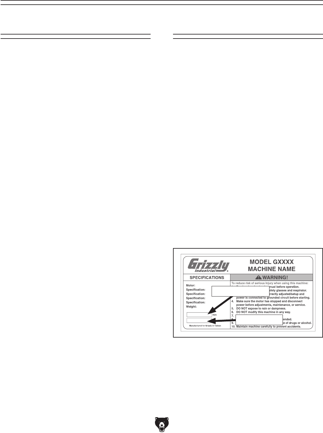
for help. Before calling, make sure you write down
the
Manufacture Date and Serial Number
from
the machine ID label (see below). This information
is required for us to provide proper tech support,
and it helps us determine if updated documenta-
tion is available for your machine.
Manufacture Date
Serial Number
Manual Accuracy
We stand behind our machines! If you have ques-
tions or need help, contact us with the information
below. Before contacting, make sure you get the
serial number
and manufacture date from the
machine ID label. This will help us help you faster.
Grizzly Technical Support
1203 Lycoming Mall Circle
Muncy, PA 17756
Phone: (570) 546-9663
Email: techsupport@grizzly.com
We want your feedback on this manual. What did
you like about it? Where could it be improved?
Please take a few minutes to give us feedback.
Grizzly Documentation Manager
P.O. Box 2069
Bellingham, WA 98227-2069
Email: manuals@grizzly.com
Contact Info
Model G0779 (Mfd. Since 09/14) -3-
Identification
To reduce your risk of
serious injury, read this
entire manual BEFORE
using machine.
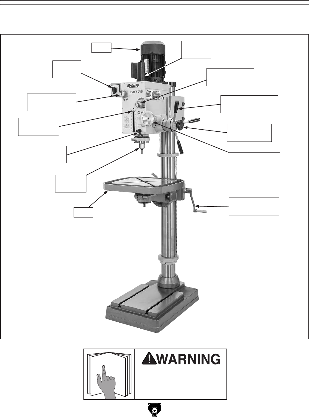
Become familiar with the names and locations of the controls and features shown below to better understand
the instructions in this manual.
Motor
Spindle Speed
Range Selector
Quill Lock
Lever
Depth Scale
& Pointer
Quill
& Spindle
Table
Table Elevation
Crank
Fine Downfeed
Handwheel
Downfeed
Selector Knob
Coarse Downfeed
Lever
Spindle Speed
Selector
Drawbar
Cover
Spindle
Switch
-4- Model G0779 (Mfd. Since 09/14)
Controls &
Components
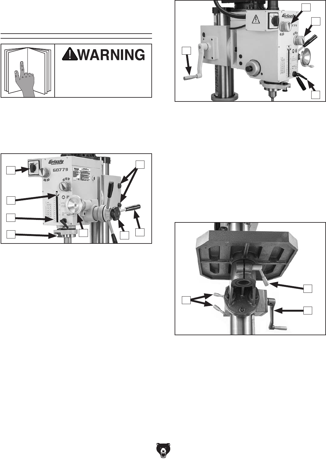
Refer to Figures 1–3 and the following descrip-
tions to become familiar with the basic controls of
this machine.
To reduce your risk of
serious injury, read this
entire manual BEFORE
using machine.
Headstock
A. Depth Stop Adjustment Knob: Determines
depth of cut.
B. Depth Scale: Indicates depth of cut.
C. Depth Stop: Stops spindle travel at pre-
determined depth.
D. Spindle Switch: Turns machine ON and
OFF. Selects direction of spindle rotation.
E. Headstock Locking Nuts: Lock headstock
in position.
F. Coarse Downfeed Levers: Provide coarse
control over vertical spindle travel.
G. Downfeed Selector Knob: Engages/disen-
gages fine downfeed handwheel.
H. Fine Downfeed Handwheel: Provides fine
control over vertical spindle travel.
Figure 2. Headstock controls (left).
L
I
J
K
I. Headstock Elevation Crank: Changes ele-
vation of entire headstock.
J. Spindle Speed Range Selector: Selects
between low and high spindle speed ranges.
K. Spindle Speed Selector: Selects one of
three spindle speeds within each range.
L. Quill Lock: Locks quill in position.
M. Table Elevation Lock Handles: Secure
table assembly to column. Unlock to raise or
lower table, or to pivot table assembly around
column.
N. Table Rotation Lock Handle: Allows table
to rotate.
O. Table Elevation Crank: Changes elevation
of table assembly.
Table
Figure 3. Table controls.
M
O
N
Figure 1. Headstock controls (right).
A
D
F
B
C
G
H
E

Model G0779 (Mfd. Since 09/14) -5-
Machine Data Sheet
The information contained herein is deemed accurate as of 5/10/2015 and represents our most recent product specifications.
Due to our ongoing improvement efforts, this information may not accurately describe items previously purchased. PAGE 1 OF 2Model G0779
MACHINE DATA
SHEET
Customer Service #: (570) 546-9663 · To Order Call: (800) 523-4777 · Fax #: (800) 438-5901
MODEL G0779 HEAVY-DUTY FLOOR MODEL GEARHEAD
DRILL PRESS
Product Dimensions:
Weight.............................................................................................................................................................. 706 lbs.
Width (side-to-side) x Depth (front-to-back) x Height........................................................................... 25 x 33 x 80 in.
Footprint (Length x Width)............................................................................................................................ 26 x 18 in.
Shipping Dimensions:
Type.......................................................................................................................................................... Wood Crate
Content........................................................................................................................................................... Machine
Weight.............................................................................................................................................................. 786 lbs.
Length x Width x Height....................................................................................................................... 29 x 30 x 72 in.
Electrical:
Power Requirement............................................................................................................ 220V, Single-Phase, 60Hz
Full-Load Current Rating....................................................................................................................................... 8.6A
Minimum Circuit Size.............................................................................................................................................. 15A
Connection Type....................................................................................................................................... Cord & Plug
Power Cord Included.............................................................................................................................................. Yes
Power Cord Length.......................................................................................................................................... 6-1/2 ft.
Power Cord Gauge......................................................................................................................................... 14 AWG
Plug Included.......................................................................................................................................................... Yes
Included Plug Type................................................................................................................................................ 6-15
Switch Type....................................................................................................................................... Forward/Reverse
Motors:
Main
Type................................................................................................................. TEFC Capacitor-Start Induction
Horsepower................................................................................................................................................ 2 HP
Phase............................................................................................................................................ Single-Phase
Amps........................................................................................................................................................... 8.6A
Speed................................................................................................................................................ 1720 RPM
Power Transfer ................................................................................................................................. Gear Drive
Bearings..................................................................................................... Shielded & Permanently Lubricated
Main Specifications:
Operation Information
Swing................................................................................................................................................... 23-3/8 in.
Drilling Capacity (Mild Steel)................................................................................................................. 1-1/4 in.
Number of Spindle Speeds............................................................................................................................... 6
Range of Spindle Speeds.......................................................................................................... 90 – 1970 RPM
Drill Chuck Type........................................................................................................................................... B16
Drill Chuck Size................................................................................................................................. 1 – 13 mm
Head Information
Max Head Tilt (Left/Right)....................................................................................................................... 90 deg.
Maximum Movement of Head Casting................................................................................................ 10-1/2 in.
Head Swivel.......................................................................................................................................... 360 deg.

-6- Model G0779 (Mfd. Since 09/14)
The information contained herein is deemed accurate as of 5/10/2015 and represents our most recent product specifications.
Due to our ongoing improvement efforts, this information may not accurately describe items previously purchased. PAGE 2 OF 2Model G0779
Spindle Information
Spindle Taper............................................................................................................................................... R-8
Spindle Travel.............................................................................................................................................. 5 in.
Distance From Spindle To Column.................................................................................................. 11-11/16 in.
Distance From Spindle To Table......................................................................................................... 26-1/2 in.
Distance From Spindle To Base........................................................................................................ 44-3/16 in.
Table Information
Table Length........................................................................................................................................ 19-5/8 in.
Table Width................................................................................................................................................ 18 in.
Table Thickness.................................................................................................................................... 1-3/4 in.
Floor To Table Height...................................................................................................................... 22-15/16 in.
Vertical Table Movement..................................................................................................................... 24-3/8 in.
Max Table Tilt (Left/Right)...................................................................................................................... 60 deg.
Table Swivel Around Center................................................................................................................. 360 deg.
Table Swivel Around Column............................................................................................................... 360 deg.
Maximum Movement Of Work Table................................................................................................... 24-3/8 in.
Number of T Slots............................................................................................................................................. 2
T Slot Width............................................................................................................................................ 9/16 in.
T Slot Length....................................................................................................................................... 18-1/2 in.
Construction
Table.................................................................................................................................................... Cast Iron
Spindle Housing................................................................................................................................... Cast Iron
Column................................................................................................................................................. Cast Iron
Head.................................................................................................................................................... Cast Iron
Base..................................................................................................................................................... Cast Iron
Paint Type/Finish.................................................................................................................................... Enamel
Other Related Information
Base Length...................................................................................................................................... 25-9/16 in.
Base Width.......................................................................................................................................... 17-3/4 in.
Quill Diameter.................................................................................................................................... 2-15/16 in.
Column Diameter................................................................................................................................... 4-1/2 in.
Other Specifications:
Country of Origin ................................................................................................................................................ China
Warranty ........................................................................................................................................................... 1 Year
Approximate Assembly & Setup Time .............................................................................................................. 1 Hour
Serial Number Location ................................................................................................................... Machine ID Label
ISO 9001 Factory .................................................................................................................................................. Yes
CSA, ETL, or UL Certified/Listed ............................................................................................................................ No
Features:
90 degree left, 90 degree right head tilt
R-8 spindle
5" spindle stroke
60 degree left, 60 degree right table tilt
23-3/8" swing
6 speeds
2 HP motor
Table equipped with lock levers
Crank handle operated rack-and-pinion vertical table and head casting movement
Drawbar thread size: 7/16-20; length: 17-3/4"

Model G0779 (Mfd. Since 09/14) -7-
ELECTRICAL EQUIPMENT INJURY RISKS. You
can be shocked, burned, or killed by touching live
electrical components or improperly grounded
machinery. To reduce this risk, only allow qualified
service personnel to do electrical installation or
repair work, and always disconnect power before
accessing or exposing electrical equipment.
DISCONNECT POWER FIRST.
Always discon-
nect machine from power supply BEFORE making
adjustments, changing tooling, or servicing machine.
This prevents an injury risk from unintended startup
or contact with live electrical components.
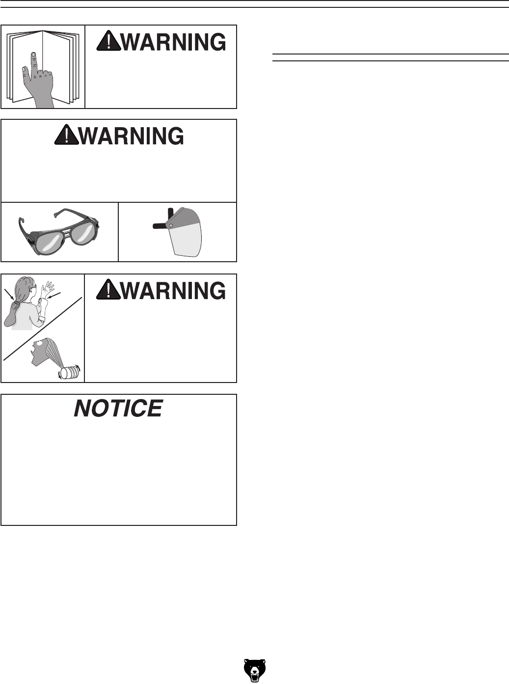
EYE PROTECTION. Always wear ANSI-approved
safety glasses or a face shield when operating or
observing machinery to reduce the risk of eye
injury or blindness from flying particles. Everyday
eyeglasses are NOT approved safety glasses.
OWNER’S MANUAL. Read and understand this
owner’s manual BEFORE using machine.
TRAINED OPERATORS ONLY. Untrained oper-
ators have a higher risk of being hurt or killed.
Only allow trained/supervised people to use this
machine. When machine is not being used, dis-
connect power, remove switch keys, or lock-out
machine to prevent unauthorized use—especially
around children. Make workshop kid proof!
DANGEROUS ENVIRONMENTS. Do not use
machinery in areas that are wet, cluttered, or have
poor lighting. Operating machinery in these areas
greatly increases the risk of accidents and injury.
MENTAL ALERTNESS REQUIRED. Full mental
alertness is required for safe operation of machin-
ery. Never operate under the influence of drugs or
alcohol, when tired, or when distracted.
For Your Own Safety, Read Instruction
Manual Before Operating This Machine
The purpose of safety symbols is to attract your attention to possible hazardous conditions.
This manual uses a series of symbols and signal words intended to convey the level of impor-
tance of the safety messages. The progression of symbols is described below. Remember that
safety messages by themselves do not eliminate danger and are not a substitute for proper
accident prevention measures. Always use common sense and good judgment.
Indicates a potentially hazardous situation which, if not avoided,
MAY result in minor or moderate injury. It may also be used to alert
against unsafe practices.
Indicates a potentially hazardous situation which, if not avoided,
COULD result in death or serious injury.
Indicates an imminently hazardous situation which, if not avoided,
WILL result in death or serious injury.
This symbol is used to alert the user to useful information about
proper operation of the machine.
NOTICE
Safety Instructions for Machinery
SECTION 1: SAFETY

-8- Model G0779 (Mfd. Since 09/14)
WEARING PROPER APPAREL. Do not wear
clothing, apparel or jewelry that can become
entangled in moving parts. Always tie back or
cover long hair. Wear non-slip footwear to reduce
risk of slipping and losing control or accidentally
contacting cutting tool or moving parts.
HAZARDOUS DUST. Dust created by machinery
operations may cause cancer, birth defects, or
long-term respiratory damage. Be aware of dust
hazards associated with each workpiece mate-
rial. Always wear a NIOSH-approved respirator to
reduce your risk.
HEARING PROTECTION. Always wear hear-
ing protection when operating or observing loud
machinery. Extended exposure to this noise
without hearing protection can cause permanent
hearing loss.
REMOVE ADJUSTING TOOLS. Tools left on
machinery can become dangerous projectiles
upon startup. Never leave chuck keys, wrenches,
or any other tools on machine. Always verify
removal before starting!
USE CORRECT TOOL FOR THE JOB. Only use
this tool for its intended purpose—do not force
it or an attachment to do a job for which it was
not designed. Never make unapproved modifica-
tions—modifying tool or using it differently than
intended may result in malfunction or mechanical
failure that can lead to personal injury or death!
AWKWARD POSITIONS. Keep proper footing
and balance at all times when operating machine.
Do not overreach! Avoid awkward hand positions
that make workpiece control difficult or increase
the risk of accidental injury.
CHILDREN & BYSTANDERS. Keep children and
bystanders at a safe distance from the work area.
Stop using machine if they become a distraction.
GUARDS & COVERS. Guards and covers reduce
accidental contact with moving parts or flying
debris. Make sure they are properly installed,
undamaged, and working correctly BEFORE
operating machine.
FORCING MACHINERY. Do not force machine.
It will do the job safer and better at the rate for
which it was designed.
NEVER STAND ON MACHINE. Serious injury
may occur if machine is tipped or if the cutting
tool is unintentionally contacted.
STABLE MACHINE. Unexpected movement dur-
ing operation greatly increases risk of injury or
loss of control. Before starting, verify machine is
stable and mobile base (if used) is locked.
USE RECOMMENDED ACCESSORIES. Consult
this owner’s manual or the manufacturer for rec-
ommended accessories. Using improper acces-
sories will increase the risk of serious injury.
UNATTENDED OPERATION. To reduce the
risk of accidental injury, turn machine OFF and
ensure all moving parts completely stop before
walking away. Never leave machine running
while unattended.
MAINTAIN WITH CARE. Follow all maintenance
instructions and lubrication schedules to keep
machine in good working condition. A machine
that is improperly maintained could malfunction,
leading to serious personal injury or death.
DAMAGED PARTS. Regularly inspect machine
for damaged, loose, or mis-adjusted parts—or
any condition that could affect safe operation.
Immediately repair/replace BEFORE operating
machine. For your own safety, DO NOT operate
machine with damaged parts!
MAINTAIN POWER CORDS. When disconnect-
ing cord-connected machines from power, grab
and pull the plug—NOT the cord. Pulling the cord
may damage the wires inside. Do not handle
cord/plug with wet hands. Avoid cord damage by
keeping it away from heated surfaces, high traffic
areas, harsh chemicals, and wet/damp locations.
EXPERIENCING DIFFICULTIES. If at any time
you experience difficulties performing the intend-
ed operation, stop using the machine! Contact our
Technical Support at (570) 546-9663.

Model G0779 (Mfd. Since 09/14) -9-
Additional Safety for Drill Presses
The primary risks of operating a Drill Press are as follows: You can be killed or seriously injured
if clothing, jewelry, or long hair gets entangled with rotating spindle or cutting tool/bit. You
can be severely cut or get your fingers amputated from contact with rotating cutting tool/bit.
You can be blinded or struck with great force by broken cutting tools, metal chips, unsecured
workpieces, chuck keys, or other adjustment tools thrown from rotating spindle. To reduce
your risk of serious injury when operating this machine, completely heed and understand the
following:
INSPECT CUTTING TOOL/BIT BEFORE USE.
Inspect cutting tools for sharpness, chips, or
cracks before each use. Replace dull, chipped,
or cracked cutting tools immediately. Damaged
bits may break apart during operation. Dull bits
increase cutting resistance and are more likely to
grab and spin/throw workpiece.
CLEAN MACHINE SAFELY. Never clear chips
while spindle is turning. Metal chips
or shav-
ings can be razor sharp. DO NOT clear chips by
hand or compressed air—use a brush or vacuum
instead.
PROPERLY MAINTAIN MACHINE. Keep machine
in proper working condition to help ensure that it
functions safely and all guards and other compo-
nents work as intended. Perform routine inspec-
tions and all necessary maintenance. Never oper-
ate machine with damaged or worn parts that can
break or result in unexpected movement during
operation.
DISCONNECT POWER FIRST. To reduce risk of
electrocution or injury from unexpected startup,
make sure drill is turned OFF, disconnected from
power, and all moving parts have come to a com-
plete stop before changing cutting tools or start-
ing any inspection, adjustment, or maintenance
procedure.
POWER DISRUPTION. In the event of a local
power outage during operation, turn spindle switch
OFF to avoid a possible sudden startup once
power is restored.
UNDERSTAND ALL CONTROLS. Make sure you
understand the function and proper use of all con-
trols before starting. This will help you avoid mak-
ing mistakes that result in serious injury.
WEAR FACE SHIELD. Always wear a face shield
in addition to safety glasses. This provides more
complete protection for your face than safety
glasses alone.
REMOVE CHUCK KEY OR TOOLS BEFORE
STARTUP. Always remove chuck key, drawbar
wrench, and other tools used on the spindle imme-
diately after use. This will prevent them from being
thrown by the spindle upon startup.
PROPERLY SECURE CUTTING TOOL/BIT.
Firmly secure cutting tool or drill bit so it does not
fly out of spindle during operation or startup.
USE CORRECT SPINDLE SPEED. Follow recom-
mended speeds and feeds for each size/type of
cutting tool/bit and workpiece material. This helps
avoid tool breakage during operation and helps
ensure best cutting results.
ALLOW SPINDLE TO STOP. To minimize risk of
entanglement, always allow spindle to stop on its
own. DO NOT stop spindle using your hand or any
other object.
SECURE WORKPIECE TO TABLE. An unsecure
workpiece may unexpectedly shift, spin out of con-
trol, or be thrown if cutting tool/bit ”grabs” during
operation. NEVER hold workpiece only by hand
during operation. Clamp workpiece to table or in a
vise mounted to table to properly secure it.

-10- Model G0779 (Mfd. Since 09/14)
SECTION 2: POWER SUPPLY
Availability
Before installing the machine, consider the avail-
ability and proximity of the required power supply
circuit. If an existing circuit does not meet the
requirements for this machine, a new circuit must
be installed. To minimize the risk of electrocution,
fire, or equipment damage, installation work and
electrical wiring must be done by an electrician or
qualified service personnel in accordance with all
applicable codes and standards.
Electrocution, fire, or
equipment damage may
occur if machine is not
correctly grounded and
connected to the power
supply.
Full-Load Current Rating
The full-load current rating is the amperage a
machine draws at 100% of the rated output power.
On machines with multiple motors, this is the
amperage drawn by the largest motor or sum of all
motors and electrical devices that might operate
at one time during normal operations.
Full-Load Current Rating at 220V .... 8.6 Amps
The full-load current is not the maximum amount
of amps that the machine will draw. If the machine
is overloaded, it will draw additional amps beyond
the full-load rating.
If the machine is overloaded for a sufficient length
of time, damage, overheating, or fire may result—
especially if connected to an undersized circuit.
To reduce the risk of these hazards, avoid over-
loading the machine during operation and make
sure it is connected to a power supply circuit that
meets the specified circuit requirements.
For your own safety and protection of
property, consult an electrician if you are
unsure about wiring practices or electrical
codes in your area.
Note: Circuit requirements in this manual apply to
a dedicated circuit—where only one machine will
be running on the circuit at a time. If machine will
be connected to a shared circuit where multiple
machines may be running at the same time, con-
sult an electrician or qualified service personnel to
ensure circuit is properly sized for safe operation.
A power supply circuit includes all electrical
equipment between the breaker box or fuse panel
in the building and the machine. The power sup-
ply circuit used for this machine must be sized to
safely handle the full-load current drawn from the
machine for an extended period of time. (If this
machine is connected to a circuit protected by
fuses, use a time delay fuse marked D.)
Circuit Information
Circuit Requirements
This machine is prewired to operate on a power
supply circuit that has a verified ground and meets
the following requirements:
Nominal Voltage ......... 208V, 220V, 230V, 240V
Cycle ..........................................................60 Hz
Phase ........................................... Single-Phase
Power Supply Circuit ......................... 15 Amps
Plug/Receptacle ............................. NEMA 6-15
Model G0779 (Mfd. Since 09/14) -11-
Improper connection of the equipment-grounding
wire can result in a risk of electric shock. The
wire with green insulation (with or without yellow
stripes) is the equipment-grounding wire. If repair
or replacement of the power cord or plug is nec-
essary, do not connect the equipment-grounding
wire to a live (current carrying) terminal.
Check with a qualified electrician or service per-
sonnel if you do not understand these grounding
requirements, or if you are in doubt about whether
the tool is properly grounded. If you ever notice
that a cord or plug is damaged or worn, discon-
nect it from power, and immediately replace it with
a new one.
Extension Cords
We do not recommend using an extension cord
with this machine.
If you must use an extension
cord, only use it if absolutely necessary and only
on a temporary basis.
Extension cords cause voltage drop, which can
damage electrical components and shorten motor
life. Voltage drop increases as the extension cord
size gets longer and the gauge size gets smaller
(higher gauge numbers indicate smaller sizes).
Any extension cord used with this machine must
be in good condition and contain a ground wire
and matching plug/receptacle. Additionally, it must
meet the following size requirements:
Minimum Gauge Size ...........................14 AWG
Maximum Length (Shorter is Better).......50 ft.
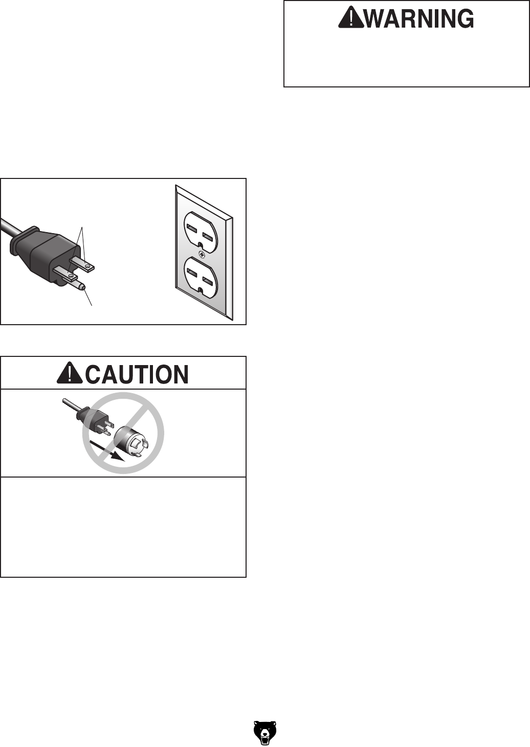
Figure 4. Typical 6-15 plug and receptacle.
Grounding Prong
Current Carrying Prongs
6-15 PLUG
GROUNDED
6-15 RECEPTACLE
Grounding Requirements
This machine MUST be grounded. In the event
of certain malfunctions or breakdowns, grounding
reduces the risk of electric shock by providing a
path of least resistance for electric current.
This machine is equipped with a power cord that
has an equipment-grounding wire and a grounding
plug. Only insert plug into a matching receptacle
(outlet) that is properly installed and grounded in
accordance with all local codes and ordinances.
DO NOT modify the provided plug!
No adapter should be used with plug. If
plug does not fit available receptacle, or if
machine must be reconnected for use on a
different type of circuit, reconnection must
be performed by an electrician or qualified
service personnel, and it must comply with
all local codes and ordinances.
Serious injury could occur if you connect
machine to power before completing setup
process. DO NOT connect to power until
instructed later in this manual.
-12- Model G0779 (Mfd. Since 09/14)
SECTION 3: SETUP
Description Qty
• Safety Glasses (for each person) ............... 1
• Cleaner/Degreaser (Page 14) .................... 1
• Disposable Shop Rags ............................... 1
• Brass Hammer ........................................... 1
• Lifting Slings (Rated for at least 800 lbs.) .. 2
• Lifting Equipment
(Rated for at least 800 lbs.) ........................ 1
• Additional People ....................................... 1
Needed for Setup
Your machine was carefully packaged for safe
transportation. Remove the packaging materials
from around your machine and inspect it. If you
discover any damage, please call us immediately
at (570) 546-9663
for advice.
Save the containers and all packing materials for
possible inspection by the carrier or its agent.
Otherwise, filing a freight claim can be difficult.
When you are completely satisfied with the condi-
tion of your shipment, inventory the contents.
Unpacking
SUFFOCATION HAZARD!
Keep children and pets away
from plastic bags or packing
materials shipped with this
machine. Discard immediately.
This machine presents
serious injury hazards
to untrained users. Read
through this entire manu-
al to become familiar with
the controls and opera-
tions before starting the
machine!
Wear safety glasses during
the entire setup process!
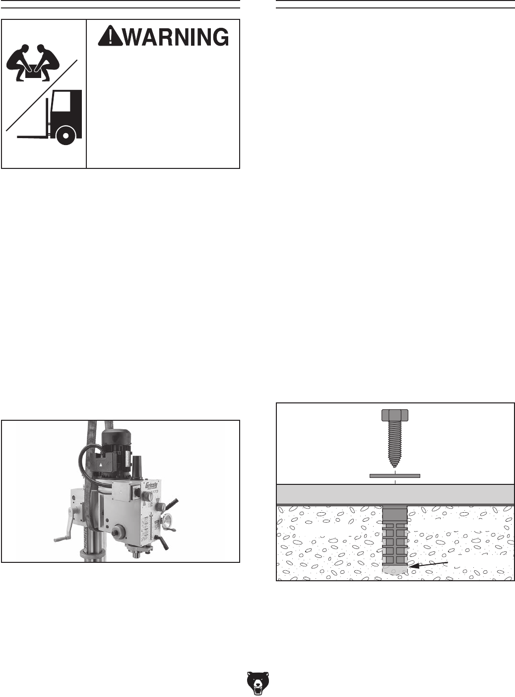
HEAVY LIFT!
Straining or crushing injury
may occur from improperly
lifting machine or some of
its parts. To reduce this risk,
get help from other people
and use a forklift (or other
lifting equipment) rated for
weight of this machine.
The following items are needed, but not included,
for the setup/assembly of this machine.
Model G0779 (Mfd. Since 09/14) -13-
NOTICE
If you cannot find an item on this list, care-
fully check around/inside the machine and
packaging materials. Often, these items get
lost in packaging materials while unpack-
ing or they are pre-installed at the factory.
Inventory
The following is a list of items shipped with your
machine. Before beginning setup, lay these items
out and inventory them.
If any non-proprietary parts are missing (e.g. a
nut or a washer), we will gladly replace them; or
for the sake of expediency, replacements can be
obtained at your local hardware store.
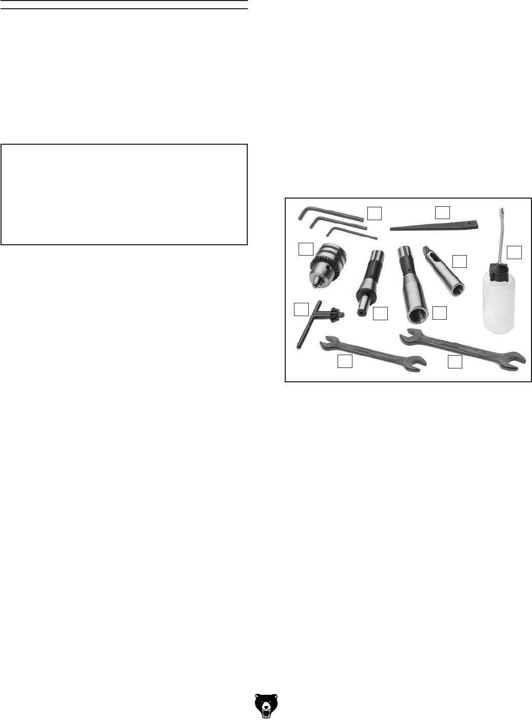
Small Item Inventory (Figure 5) Qty
A. Hex Wrench (3, 4, 5mm) ......................1 Ea.
B. Drift Key ...................................................... 1
C. Bottle for Oil ............................................... 1
D. Open-End Wrench 22–24mm..................... 1
E. Open-End Wrench 17–19mm ..................... 1
F. Drill Chuck Key ........................................... 1
G. Drill Chuck B16, 1–13mm ........................... 1
H. Drill Chuck Arbor R-8–MT#3 ...................... 1
I. Spindle Sleeve R-8–MT#3 ......................... 1
J. Spindle Sleeve MT#3–MT#2 ...................... 1
K. Hardware Bag (Not Shown) ........................ 1
— Hex Nuts M12-1.75 .................................. 2
— T-Bolts M12-1.75 x 55.............................. 2
—Flat Washers 12mm ................................ 2
L. Toolbox (Not Shown) .................................. 1
Figure 5. Model G0779 toolbox contents.
B
A
C
D
E
F
G
I
J
H
-14- Model G0779 (Mfd. Since 09/14)
The unpainted surfaces of your machine are
coated with a heavy-duty rust preventative that
prevents corrosion during shipment and storage.
This rust preventative works extremely well, but it
will take a little time to clean.
Be patient and do a thorough job cleaning your
machine. The time you spend doing this now will
give you a better appreciation for the proper care
of your machine's unpainted surfaces.
There are many ways to remove this rust preven-
tative, but the following steps work well in a wide
variety of situations. Always follow the manufac-
turer’s instructions with any cleaning product you
use and make sure you work in a well-ventilated
area to minimize exposure to toxic fumes.
Before cleaning, gather the following:
• Disposable rags
• Cleaner/degreaser (WD•40 works well)
• Safety glasses & disposable gloves
• Plastic paint scraper (optional)
Basic steps for removing rust preventative:
1.
Put on safety glasses.
2.
Coat the rust preventative with a liberal
amount of cleaner/degreaser, then let it soak
for 5–10 minutes.
3.
Wipe off the surfaces. If your cleaner/degreas-
er is effective, the rust preventative will wipe
off easily. If you have a plastic paint scraper,
scrape off as much as you can first, then wipe
off the rest with the rag.
4.
Repeat Steps 2–3 as necessary until clean,
then coat all unpainted surfaces with a quality
metal protectant to prevent rust.
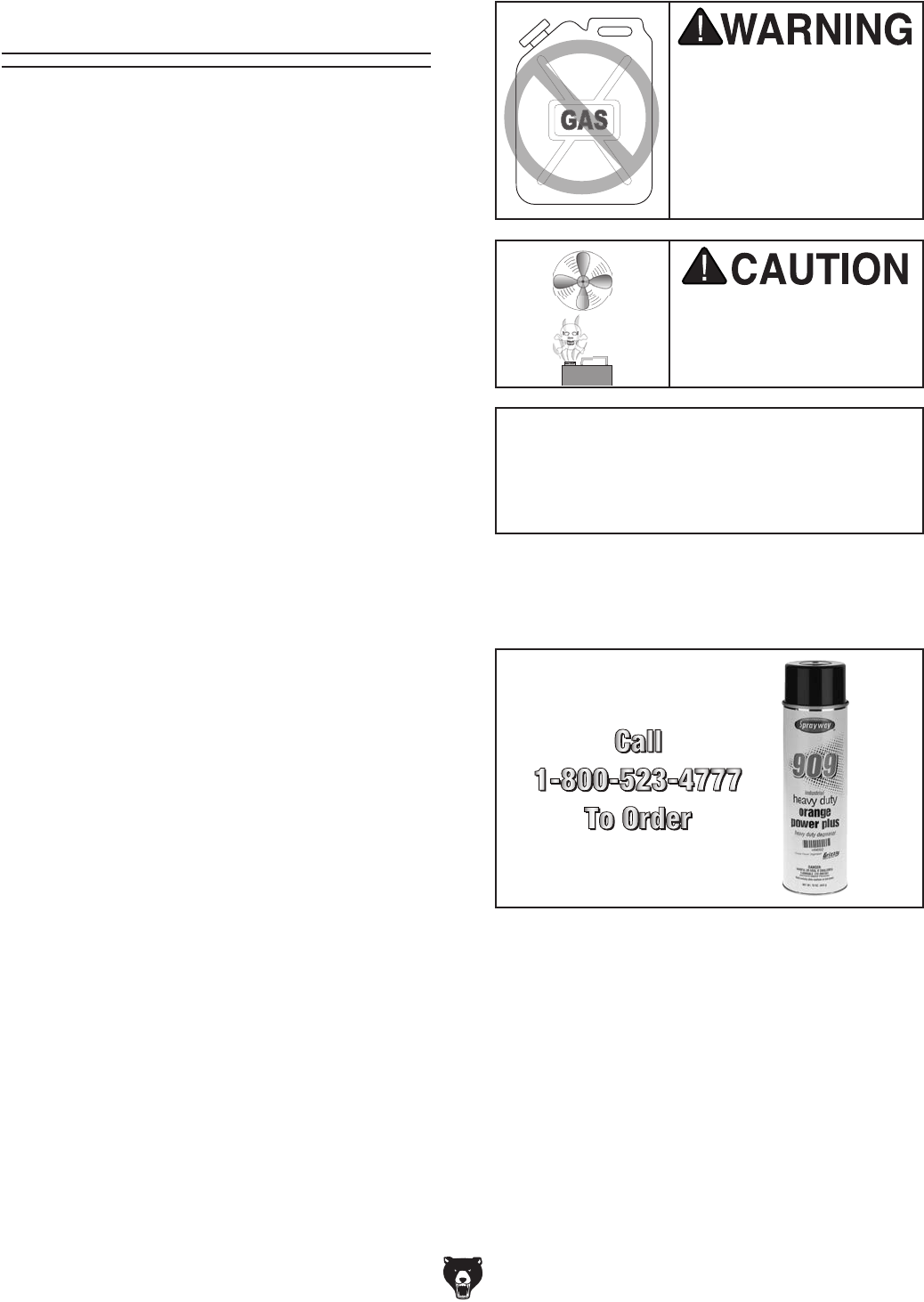
Gasoline and petroleum
products have low flash
points and can explode
or cause fire if used to
clean machinery. Avoid
using these products
to clean machinery.
Many cleaning solvents
are toxic if inhaled. Only
work in a well-ventilated
area.
NOTICE
Avoid chlorine-based solvents, such as
acetone or brake parts cleaner, that may
damage painted surfaces.
T23692—Orange Power Degreaser
A great product for removing the waxy shipping
grease from your machine during clean up.
Figure 6. T23692 Orange Power Degreaser.
Cleanup
Model G0779 (Mfd. Since 09/14) -15-
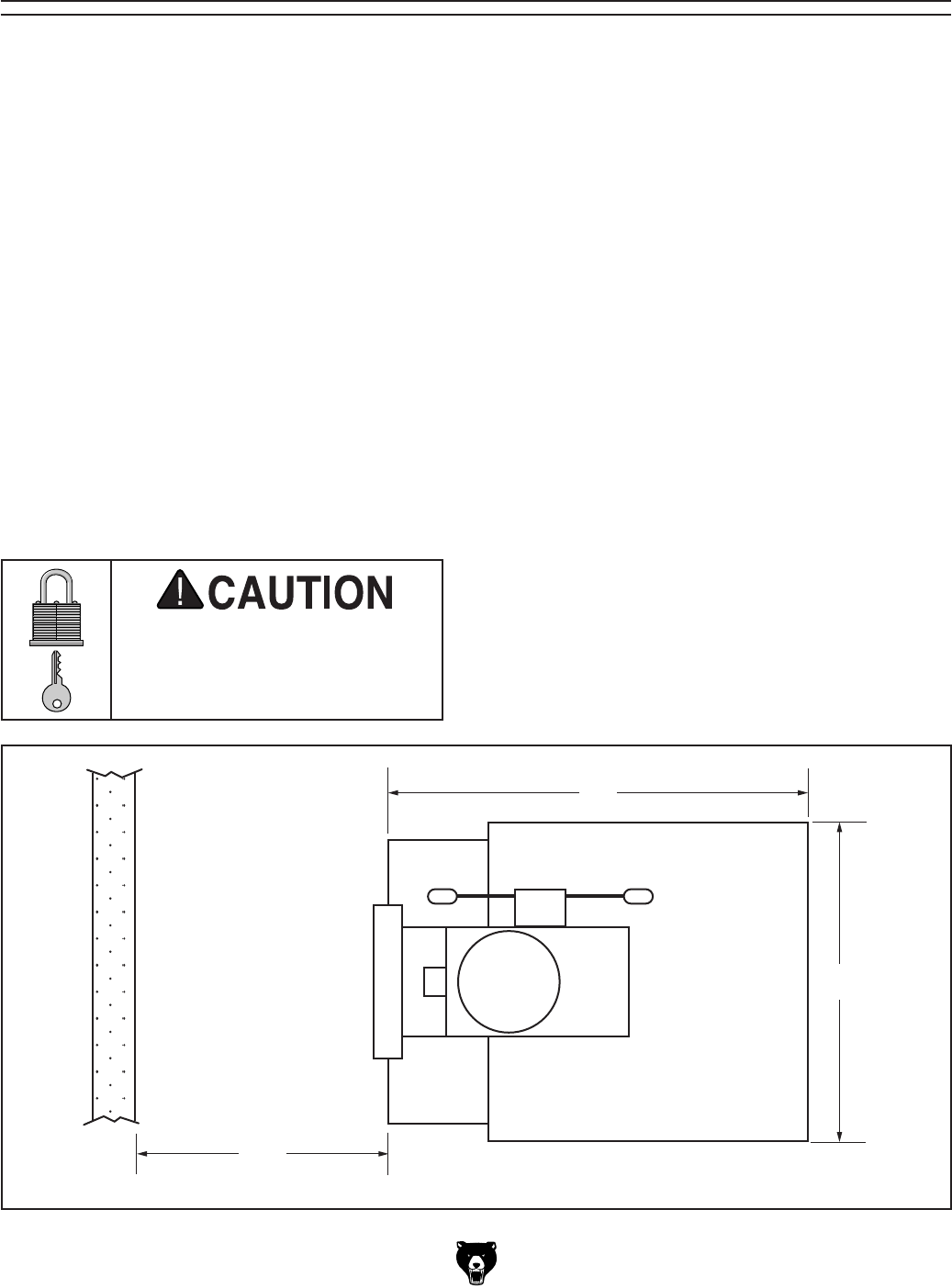
Site Considerations
Figure 7. Minimum working clearances.
33"
25"
Wall
30"
Minimum
For Maintenance
Weight Load
Refer to the
Machine Data Sheet for the weight
of your machine. Make sure that the surface upon
which the machine is placed will bear the weight
of the machine, additional equipment that may be
installed on the machine, and the heaviest work-
piece that will be used. Additionally, consider the
weight of the operator and any dynamic loading
that may occur when operating the machine.
Space Allocation
Consider the largest size of workpiece that will
be processed through this machine and provide
enough space around the machine for adequate
operator material handling or the installation of
auxiliary equipment. With permanent installations,
leave enough space around the machine to open
or remove doors/covers as required by the main-
tenance and service described in this manual.
See below for required space allocation.
Physical Environment
The physical environment where the machine is
operated is important for safe operation and lon-
gevity of machine components. For best results,
operate this machine in a dry environment that is
free from excessive moisture, hazardous chemi-
cals, airborne abrasives, or extreme conditions.
Extreme conditions for this type of machinery are
generally those where the ambient temperature
range exceeds 41°–104°F; the relative humidity
range exceeds 20%–95% (non-condensing); or
the environment is subject to vibration, shocks,
or bumps.
Electrical Installation
Place this machine near an existing power source.
Make sure all power cords are protected from
traffic, material handling, moisture, chemicals, or
other hazards. Make sure to leave enough space
around machine to disconnect power supply or
apply a lockout/tagout device, if required.
Lighting
Lighting around the machine must be adequate
enough that operations can be performed safely.
Shadows, glare, or strobe effects that may distract
or impede the operator must be eliminated.
Children or untrained people
may be seriously injured by
this machine. Only install in an
access restricted location.
-16- Model G0779 (Mfd. Since 09/14)
Lifting & Placing
HEAVY LIFT!
Straining or crushing injury
may occur from improperly
lifting machine or some of
its parts. To reduce this risk,
get help from other people
and use a forklift (or other
lifting equipment) rated for
weight of this machine.
Anchoring to Floor
Anchoring machinery to the floor prevents tipping
or shifting and reduces vibration that may occur
during operation, resulting in a machine that runs
slightly quieter and feels more solid.
If the machine will be installed in a commercial or
workplace setting, or if it is permanently connect-
ed (hardwired) to the power supply, local codes
may require that it be anchored to the floor.
If not required by any local codes, fastening the
machine to the floor is an optional step. If you
choose not to do this with your machine, we rec-
ommend placing it on machine mounts, as these
provide an easy method for leveling and they have
vibration-absorbing pads.
Lag shield anchors with lag screws (see below)
are a popular way to anchor machinery to a con-
crete floor, because the anchors sit flush with the
floor surface, making it easy to unbolt and move
the machine later, if needed. However, anytime
local codes apply, you MUST follow the anchoring
methodology specified by the code.
Machine Base
Concrete
Lag Screw
Lag Shield Anchor
Flat Washer
Drilled Hole
Figure 9. Popular method for anchoring
machinery to a concrete floor.
Anchoring to Concrete Floors
Number of Mounting Holes ............................ 4
Diameter of Mounting Hardware ................. 1⁄2"
To lift and place the machine:
1. Move shipping crate next to intended location
of drill press, then remove top portion of crate
from shipping pallet.
2. To help balance machine when moving,
move table as close to base as possible, and
raise headstock to its highest position.
3. Place lifting sling around headstock (see
Figure 8), and attach it securely to forklift (or
other power lifting equipment).
Note: Make sure you tighten all locks that
restrict moving parts to avoid sudden shifts
which could unbalance machine.
Figure 8. Typical lifting sling position.
4. Unbolt machine from pallet.
5. With another person to help to steady
machine, lift it just enough to clear pallet and
any floor obstacles, then place it in its final
position on shop floor.
Model G0779 (Mfd. Since 09/14) -17-
GEARBOX MUST
BE FILLED WITH OIL!
OIL MAY NOT BE
SHIPPED WITH MACHINE!
Refer to Lubrication Section
for Correct Oil Type.
Initial Lubrication
To prevent spillage, this machine was shipped
from the factory without any oil in it. The head-
stock oil reservoir must be properly filled with oil
before the drill press can be operated for the first
time. Refer to the Lubrication section, beginning
on Page 31, for details on how to check and add
oil.
Arbor/Chuck
Assembly
Damage caused by running the drill press
without oil in the reservoir will not be cov-
ered under warranty.
An arbor is included for the drill chuck that
comes with this machine. The following procedure
describes how to install the arbor in the chuck.
After the arbor is installed in the drill chuck, it
is very difficult to separate the assembly. If you
would like to use a different chuck in the future,
we recommend obtaining a new arbor.
Important: DO NOT install the drill chuck and
arbor assembly into the spindle until AFTER the
test run.
To join drill chuck and arbor:
1.
Use acetone or lacquer thinner to
clean drill
chuck and arbor mating surfaces, especially
the bore.
2.
Retract chuck jaws completely into chuck.
3.
Insert small end of arbor into chuck.
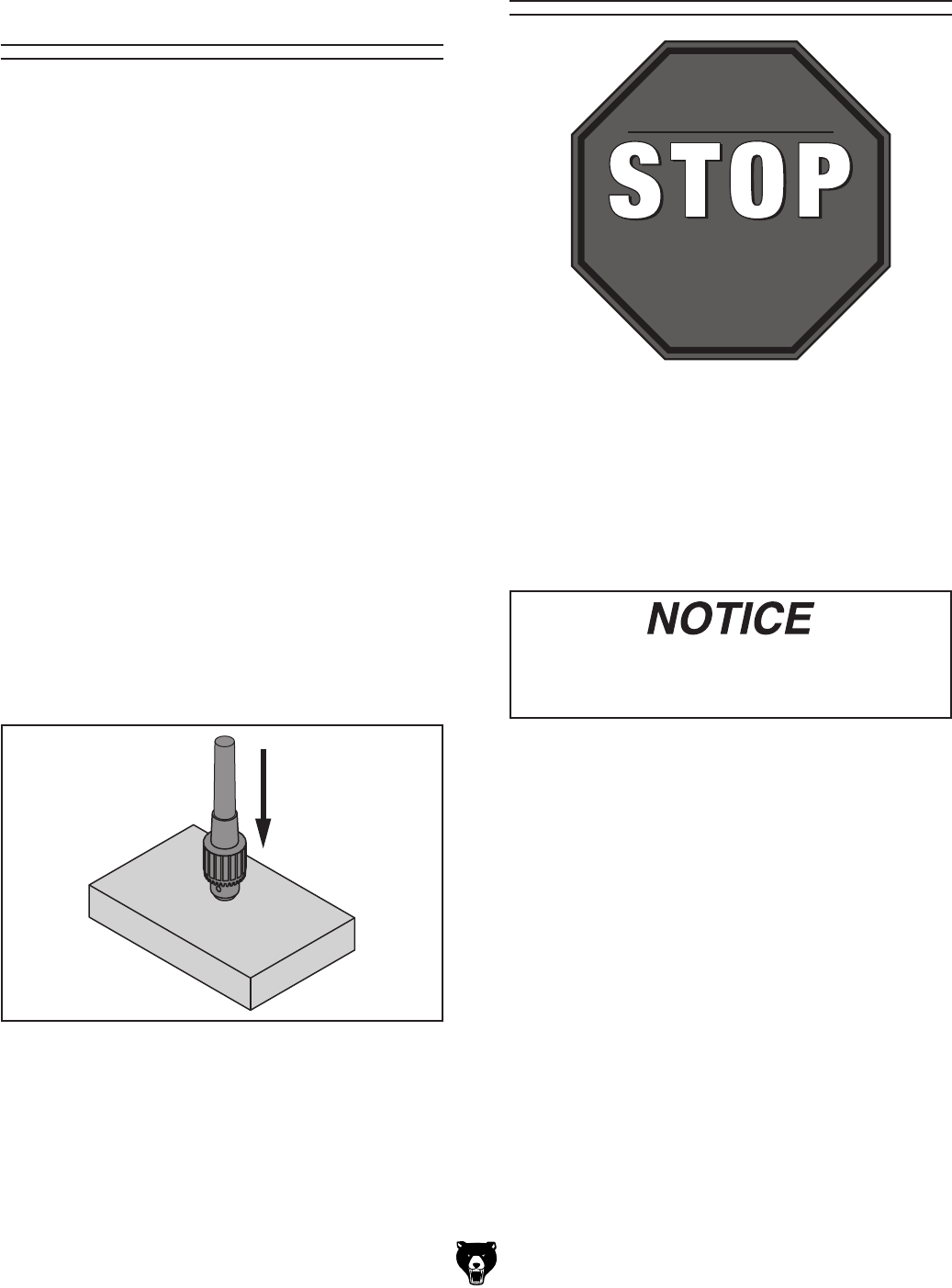
4.
Hold assembly by the arbor and tap chuck
onto a block of wood with medium force, as
illustrated below.
5. Attempt to separate drill chuck and arbor by
hand —if they separate, repeat Steps 3–4.
Figure 10. Arbor/chuck assembly.
-18- Model G0779 (Mfd. Since 09/14)
Test Run
Once assembly is complete, test run the machine
to ensure it is properly connected to power and
safety components are functioning properly.
If you find an unusual problem during the test run,
immediately stop the machine, disconnect it from
power, and fix the problem BEFORE operating the
machine again. The
Troubleshooting
table in the
SERVICE section of this manual can help.
DO NOT start machine until all preceding
setup instructions have been performed.
Operating an improperly set up machine
may result in malfunction or unexpect-
ed results that can lead to serious injury,
death, or machine/property damage.
Serious injury or death can result from
using this machine BEFORE understanding
its controls and related safety information.
DO NOT operate, or allow others to operate,
machine until the information is understood.
To test run machine:
1. Clear all setup tools away from machine.
2. Connect machine to power supply.
3. Set spindle speed to 90 RPM (see Page 25).
4. Rotate spindle switch to RIGHT to turn
machine ON. Verify motor operation, then
turn machine OFF. The motor should run
smoothly and without unusual problems or
noises. Repeat with switch set to LEFT.
Make sure headstock has proper amount of
oil before performing Test Run and Spindle
Break-In. Otherwise, headstock compo-
nents may be damaged and void warranty.
Refer to Page 32 for detailed instructions.
Spindle Break-In
Do not leave drill press unattended dur-
ing Spindle Break-In procedure. If your
attention is needed elsewhere during this
procedure, turn machine OFF and restart
procedure later from the beginning.
To perform spindle break-in procedure:
1. Make sure spindle is completely stopped,
then set spindle speed to 90 RPM (refer to
Page 25 for detailed instructions).
2. Run machine for a minimum of 5 minutes in
each spindle direction.
3. Repeat Step 2 for each of the spindle speeds.
4. Change headstock oil (refer to Page 31 for
detailed instructions).
Congratulations! The test run and spindle break-in
are now complete!
The spindle break-in procedure distributes lubri-
cation
throughout the bearings to
reduce the risk
of early
bearing failure
if there are any "dry" spots
or areas where lubrication has settled in the bear-
ings. You
must complete this procedure before
placing
operational loads on the spindle for the
first time when the machine is new or if it has
been sitting idle for longer than 6 months.
Always start the spindle break-in at the lowest
speed to minimize wear if there
are dry spots.
Allow the spindle to run long enough to warm up
and distribute the bearing grease, then incremen-
tally increase spindle speeds, allowing the spindle
to run the same amount of time at each speed, until
reaching the maximum spindle speed. Following
the break-in procedure in this progressive man-
ner helps minimize any potential wear that could
occur until lubrication is fully distributed.
Model G0779 (Mfd. Since 09/14) -19-
SECTION 4: OPERATIONS
Operation Overview
The purpose of this overview is to provide the nov-
ice machine operator with a basic understanding
of how the machine is used during operation, so
the
machine controls/components
discussed later
in this manual
are easier to understand.
Due to the generic nature of this overview, it is
not
intended to be an instructional guide. To learn
more about specific operations,
read this entire
manual and
seek additional training from expe-
rienced
machine operators, and do additional
research outside of this manual by reading "how-
to" books, trade magazines, or websites.
To complete a typical operation, the operator
does the following:
1. Examines workpiece to make sure it is suit-
able for drilling.
2. Installs correct tooling for the operation.
3. Firmly secures workpiece to table using a
vise or T-slot clamps.
4. Adjusts table to correct height, then locks it in
place.
5. Adjusts headstock elevation to correct height,
then locks it in place.
6. Puts on required safety glasses and face
shield.
7. Connects machine to power.
8. Selects spindle RPM with speed control
levers and rotates spindle direction switch to
turn machine ON.
9. Begins drilling.
10. When finished, rotates spindle direction
switch to STOP and disconnects machine
from power.
To reduce your risk of
serious injury, read this
entire manual BEFORE
using machine.
If you are not experienced with this type
of machine, WE STRONGLY RECOMMEND
that you seek additional training outside of
this manual. Read books/magazines or get
formal training before beginning any proj-
ects. Regardless of the content in this sec-
tion, Grizzly Industrial will not be held liable
for accidents caused by lack of training.
Keep hair, clothing, and
jewelry away from mov-
ing parts at all times.
Entanglement can result
in death, amputation, or
severe crushing injuries!
To reduce risk of eye or face injury from
flying chips, always wear approved safety
glasses and a face shield when operating
this machine.
-20- Model G0779 (Mfd. Since 09/14)
Positioning Table
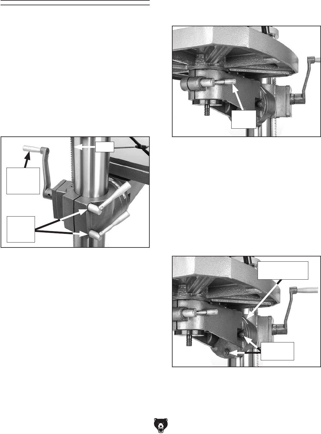
The table moves vertically, rotates 360°, pivots
around the column, and tilts 60° left or right.
1. Remove any loose objects from table surface.
2. Loosen lock handle shown in Figure 12.
Figure 12. Lock handle for controlling table
rotation.
1. Remove any loose objects from table surface.
2. Loosen table lock handles (see Figure 11).
3. Pivot table to desired location.
Note: Ensure rack (see Figure 11) moves
smoothly around column without binding in
upper/lower guide rings.
4. Retighten lock handles.
1. Remove any loose objects from table surface.
2. Loosen table lock handles shown in Figure 11.
3. Adjust table height by rotating table elevation
crank (see Figure 11), then retighten table
lock handles.
Figure 11. Table elevation and rotation controls.
Table
Lock
Handles
Table
Elevation
Crank
Tool Needed Qty
Open-End Wrench 19mm .................................. 1
Raising/Lowering Table
Pivoting Table Around Column
Rotating Table
1. Remove all objects from table surface.
2. Loosen three hex nuts shown in Figure 13.
3. Tilt table until pointer aligns with desired
angle on scale (see Figure 13).
3. Rotate table to desired position, then retighten
lock handle.
Tilt Angle
Pointer & Scale
Hex Nuts
(2 of 3)
Tilting Table
4. Retighten hex nuts.
Figure 13. Table tilt controls.
Rack
Lock
Handle
Model G0779 (Mfd. Since 09/14) -21-
Positioning
Headstock
4. Retighten hex nuts before connecting to
power.
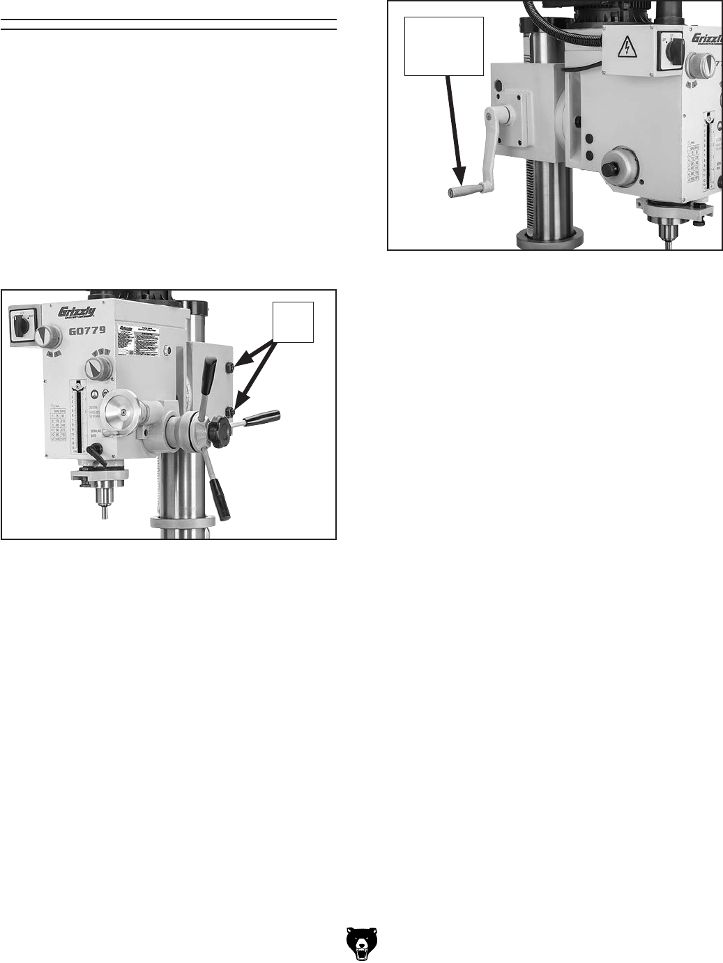
The Model G0779 headstock moves vertically,
pivots 360° around the column, and tilts 90° left
or right.
Tools Needed Qty
Wrench 24mm ................................................... 1
Wrench 22mm ................................................... 1
1. DISCONNECT MACHINE FROM POWER!
2. Loosen two hex nuts shown in Figure 14.Figure 15. Location of head elevation crank.
Head
Elevation
Crank
1. DISCONNECT MACHINE FROM POWER!
2. Loosen hex nuts shown in Figure 14.
3. Make sure headstock and cords can move
unobstructed, then manually rotate head-
stock around column Figure 15.
4. Retighten hex nuts before connecting to
power.
3. Use head elevation crank shown in Figure 15
to adjust headstock height.
Raising/Lowering Headstock
Pivoting Headstock Around Column
Figure 14. Location of hex nuts that lock
headstock to column.
Hex
Nuts
-22- Model G0779 (Mfd. Since 09/14)
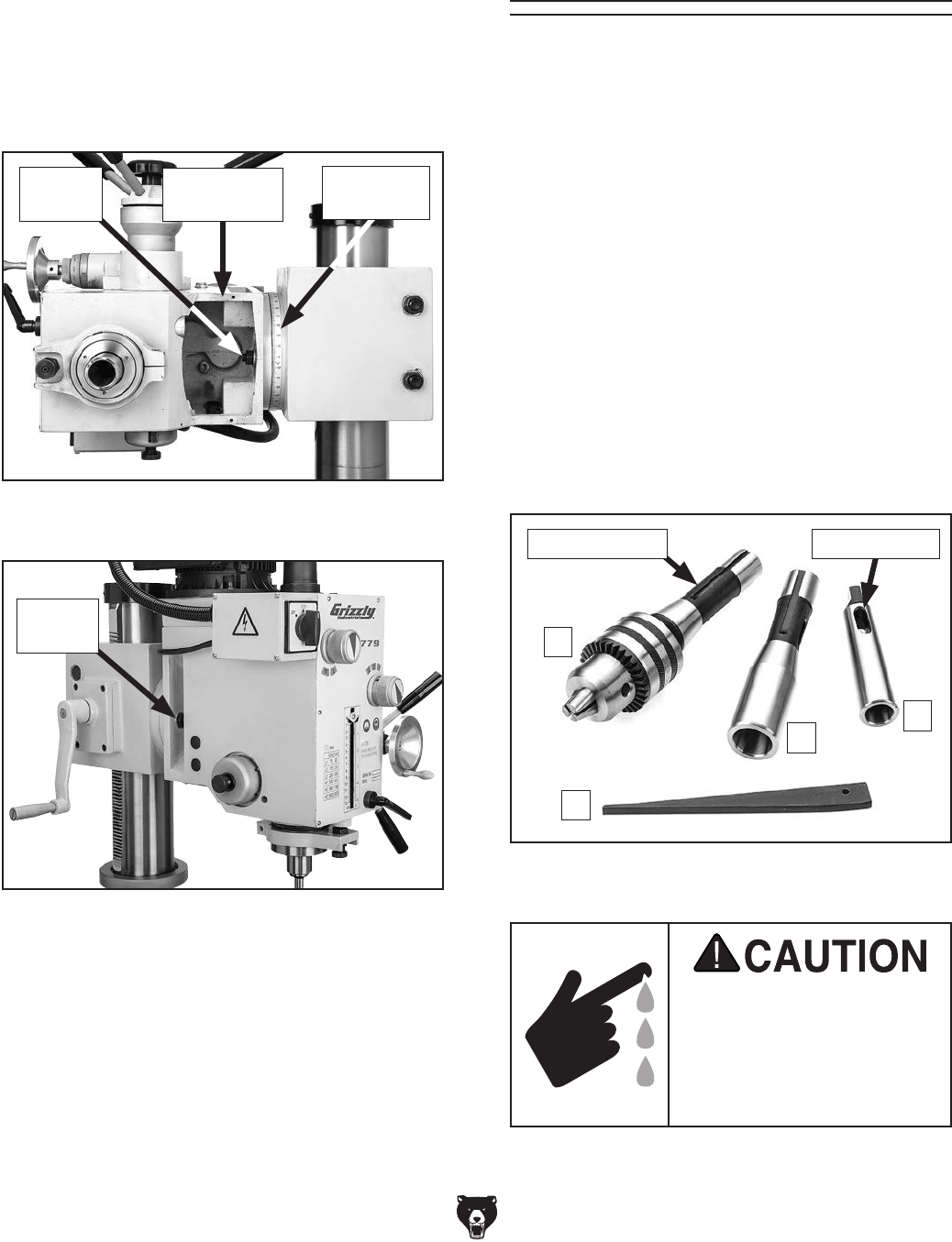
Installing/Removing
Tooling
This machine features a spindle that accepts R-8
collets and arbors. It can also use MT#3 or MT#2
tooling with the included adapter sleeves.
The Model G0779 includes the following spindle
tools (see Figure 18):
A. B16 Drill Chuck w/R-8 Arbor. Refer to
Arbor/Chuck Assembly on Page 17.
B. R-8–MT#3 Spindle Sleeve. Used for MT#3
tools and will accommodate tools with a tang.
It also has a drift key slot for tool removal.
C. MT#3–MT#2 Spindle Sleeve. Used with the
R-8–MT#3 spindle sleeve for MT#2 tools and
has a drift key slot for tool removal.
D. Drift Key: Use for tool removal.
Cutting tools are sharp and
can easily cause laceration
injuries. Always protect
your hands with leather
gloves or shop rags when
handling cutting tools.
Figure 18. Drill chuck, arbors, and drift key
included with Model G0779.
A
B
C
Alignment Slot Drift Key Slot
4. Using headstock tilt scale shown in Figure
16 as a guide, swivel headstock to desired
position, then retighten tilt-lock hex nuts and
replace cover plate.
Tilting Headstock
1. DISCONNECT MACHINE FROM POWER!
2. Remove cover plate from bottom of head-
stock (see Figure 16). The plate is secured
with (4) M4-.7 x 6 button head cap screws.
3. Loosen three tilt-lock hex nuts (see Figures
17–16).
Figure 17. Location of tilt-lock hex nuts
(one on each side of head).
Hex Nut
(1 of 3)
Figure 16. Location of tilt-lock hex nut
underneath headstock, and tilt scale.
Headstock
Tilt Scale
Hex Nut
(1 of 3)
Cover Plate
Removed
D
Model G0779 (Mfd. Since 09/14) -23-
Installing Tooling
4. Working from the top, thread drawbar into
tool by hand until it is snug, then use a 19mm
wrench to tighten it.
Note: Do not overtighten drawbar.
Overtightening makes tool removal difficult
and will damage arbor and threads.
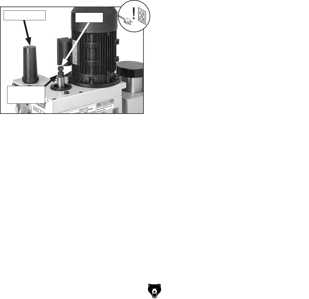
5. Re-install drawbar cap.
Figure 19. Drawbar components used when
installing/removing tooling.
Drawbar Cap
Adjustment
Nut
Drawbar
Tool Needed Qty
Open-End Wrench 19mm .................................. 1
To install tooling:
1. DISCONNECT MACHINE FROM POWER!
2. Remove drawbar cap, as shown in Figure 19.
3. Align tool alignment slot (see Figure 18 on
Page 22) with pin inside spindle, then insert
tooling into spindle until it contacts drawbar.
Note: Height of drawbar inside spindle can
be changed by rotating adjustment nut (see
Figure 19).
Tools Needed Qty
Wrench 19mm ................................................... 1
Brass Head or Dead Blow Hammer .................. 1
Removing Tooling
To remove tooling:
1. DISCONNECT MACHINE FROM POWER!
2. Remove drawbar cap and unthread drawbar
from tool one full rotation.
Note: Do not fully unthread tool from drawbar,
or drawbar and tool threads could be dam-
aged in next step.
3. Tap top of drawbar with hammer to unseat
taper.
4. Hold onto tool with one hand and fully
unthread drawbar.
-24- Model G0779 (Mfd. Since 09/14)
Using Spindle
Downfeed Controls
The depth stop limits the drilling depth or down-
ward movement of the cutting tool. Maximum
depth is 5". This is useful when performing the
same operation multiple times.
To set depth stop:
1. DISCONNECT MACHINE FROM POWER!
2. Install tooling (refer to Page 23), then make
sure spindle is drawn all the way up into
headstock.
3. Loosen hex nuts that lock headstock, and
lower headstock (see Raising/Lowering
Headstock on Page 21) until tooling is
approximately 1⁄8" above workpiece, then
retighten hex nuts.
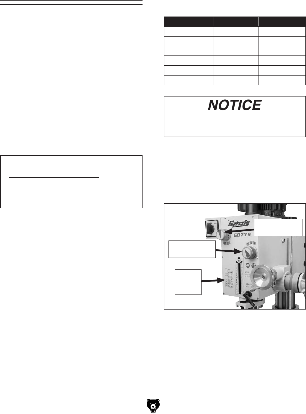
4. Rotate depth stop adjustment knob until top
of depth stop pointer is level with desired
depth as listed on scale (see Figure 21).
Note: The depth stop scale functions as
a general guide only. It is not intended for
low-tolerance, precision results. To calibrate
the depth stop see Calibrating Depth Stop
on Page 36.
Setting Depth Stop
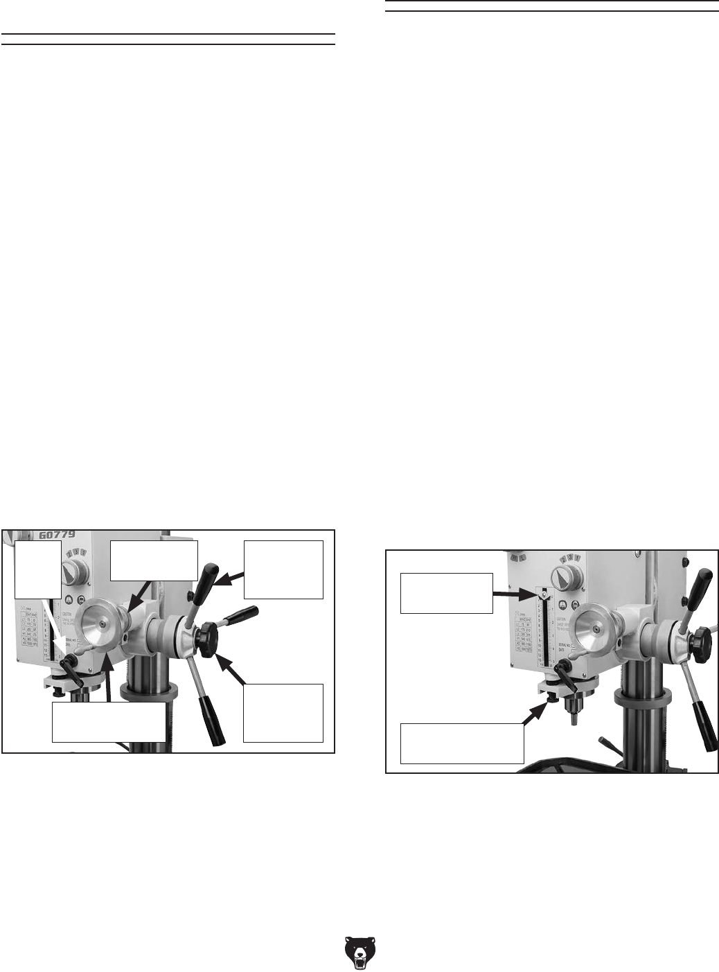
Fine Downfeed
Handwheel
Downfeed
Selector
Knob
Coarse
Downfeed
Levers
Handwheel
Dial
Quill
Lock
Lever
Figure 20. Downfeed controls.
Figure 21. Location of depth stop controls.
This machine has coarse downfeed levers and a
fine downfeed handwheel.
To operate the downfeed levers, simply pull for-
ward and down on the lever nearest you. The
spindle will go down as far as it can until you stop
pulling or until it hits the depth stop, then it will
automatically return to the top when you release
pressure on the handle.
Note: Do not let go of the handle until the spindle
returns to the top position or the spindle will slam
upward into the quill.
Use the fine downfeed handwheel to control
the spindle travel up or down in slow, small
amounts. If necessary, you can lock the quill/
spindle in a lower position with the quill lock lever
(see Figure 20).
To operate fine downfeed handwheel:
1. Tighten downfeed selector knob, shown
in Figure 20. This transfers control from
downfeed levers to fine downfeed handwheel.
2. Loosen thumb screw on rim surface of
handwheel dial, turn dial until "0" lines up
with index line, then retighten thumb screw.
3. Rotate handwheel to move quill/spindle up or
down. Each complete revolution equals 0.1".
Depth Stop
Adjustment Knob
Depth Stop
Pointer
Model G0779 (Mfd. Since 09/14) -25-
Using the correct spindle speed is important for
safe and satisfactory results, as well as maximiz-
ing tool life.
To set the spindle speed for your operation, you
will need to: 1) Determine the best spindle speed
for the cutting task, and 2) configure the spindle
speed levers to produce the required spindle
speed.
Determining Spindle Speed
Many variables affect the optimum spindle speed
to use for any given operation, but the two most
important are the recommended cutting speed
for the workpiece material and the diameter of
the cutting tool, as noted in the formula shown in
Figure 22.
Cutting speed, typically defined in feet per minute
(FPM), is the speed at which the edge of a tool
moves across the material surface.
A recommended cutting speed is an ideal speed
for cutting a type of material in order to produce
the desired finish and optimize tool life.
The books Machinery’s Handbook or Machine
Shop Practice, and some internet sites, pro-
vide excellent recommendations for which cutting
speeds to use when calculating the spindle speed.
These sources also provide a wealth of additional
information about the variables that affect cutting
speed and they are a good educational resource.
Also, there are a large number of easy-to-use
spindle speed calculators that can be found on
the internet. These sources will help you take into
account the applicable variables in order to deter-
mine the best spindle speed for the operation.
Cutting Speed (FPM) x 12
*Recommended
Tool Dia. (in inches) x 3.14
=
Spindle
Speed
(RPM)
*Double if using carbide cutting tool
Figure 22. Spindle speed formula for drills.
Spindle Speed Setting Spindle Speed
Use the chart below or the one on the headstock
when setting the spindle speed.
Spindle Speed Range Lever Speed Lever
90 RPM L 1
210 RPM L 2
345 RPM L 3
670 RPM H 1
1180 RPM H 2
1970 RPM H 3
Change spindle speed ONLY when the
spindle is completely stopped. Otherwise,
machine damage could occur.
With the spindle completely stopped, position the
spindle speed selectors (see Figure 23) to set the
spindle speed.
Note: If necessary, rotate the spindle by hand to
mesh the gears when changing speeds.
Figure 23. Spindle speed controls.
Spindle
Speed
Chart
Spindle Speed
Range Selector
Spindle Speed
Selector
-26- Model G0779 (Mfd. Since 09/14)
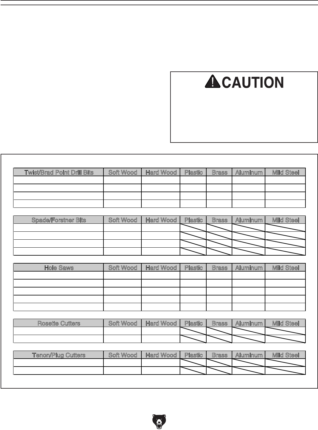
Calculating Spindle Speed for Drilling
Twist/Brad Point Drill Bits Soft Wood Hard Wood Plastic Brass Aluminum Mild Steel
1/16" – 3/16" 3000 2500 2500 2500 3000 2500
13/64" – 3/8" 2000 1500 2000 1250 2500 1250
25/64" – 5/8" 1500 750 1500 750 1500 600
11/16" – 1" 750 500 1000 400 1000 350
Spade/Forstner Bits Soft Wood Hard Wood Plastic Brass Aluminum Mild Steel
1/4" – 1/2" 2000 1500
9/16" – 1" 1500 1250
1-1/8" – 1-7/8" 1000 750
2–3" 500 350
Hole Saws Soft Wood Hard Wood Plastic Brass Aluminum Mild Steel
1/2" – 7/8" 500 500 600 600 600 500
1" – 1-7/8" 400 400 500 500 500 400
2" – 2-7/8" 300 300 400 400 400 300
3" – 3-7/8" 200 200 300 300 300 200
4" – 5" 100 100 200 200 200 100
Rosette Cutters Soft Wood Hard Wood Plastic Brass Aluminum Mild Steel
Carbide Insert Type 350 250
One-Piece Type 1800 500
Tenon/Plug Cutters Soft Wood Hard Wood Plastic Brass Aluminum Mild Steel
3/8" – 1/2" 1200 1000
5/8" – 1" 800 600
Using the Drilling Speed Chart
The chart shown in Figure 24 is intended as
a guide only. Always follow the manufacturer's
speed recommendations if provided with your
drill bits, cutters, or hole saws. Exceeding the
recommended speeds may be dangerous to the
operator.
The speeds shown here are intended to get you
started. The optimum speed will always depend
on various factors, including tool diameter, drilling
pressure, material hardness, material quality, and
desired finish.
Often, when drilling materials other than wood,
some type of lubrication is necessary.
Lubrication Suggestions
Wood ...........................................................None
Plastics ............................................Soapy Water
Brass ...............................Water-Based Lubricant
Aluminum ..................... Paraffin-Based Lubricant
Mild Steel ............................. Oil-Based Lubricant
Larger bits turning at slower speeds tend
to grab the workpiece aggressively. This
can result in the operator's hand being
pulled into the bit or the workpiece being
thrown with great force. Always clamp the
workpiece to the table to prevent injuries.
Figure 24. Drilling speed chart.
Model G0779 (Mfd. Since 09/14) -27-
SECTION 5: ACCESSORIES
ACCESSORIES
Installing unapproved accessories may
cause machine to malfunction, resulting in
serious personal injury or machine damage.
To reduce this risk, only install accessories
recommended for this machine by Grizzly.
NOTICE
Refer to our website or latest catalog for
additional recommended accessories.
order online at www.grizzly.com or call 1-800-523-4777
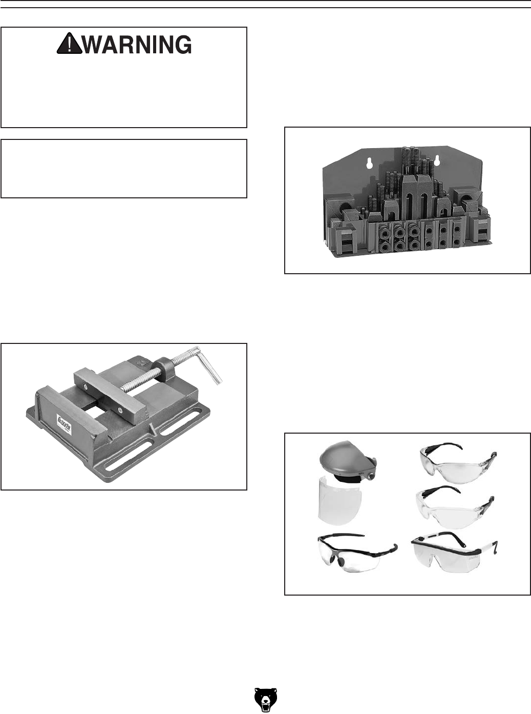
T20501—Face Shield Crown Protector 4"
T20502—Face Shield Crown Protector 7"
T20503—Face Shield Window
T20452—"Kirova" Anti-Reflective S. Glasses
T20451—"Kirova" Clear Safety Glasses
H0736—Shop Fox® Safety Glasses
H7194—Bifocal Safety Glasses 1.5
H7195—Bifocal Safety Glasses 2.0
H7196—Bifocal Safety Glasses 2.5
Figure 27. Assorted safety glasses.
G5753—Drill Press Vise - 6"
If you use a drill press and value your fingers, you
need one of these. Made from high-grade cast
iron, these hefty horizontal vises offer support
and stability, allowing you to keep your hands well
away from fast moving bits and cutters. Includes
a sturdy lip along both sides of the base, allowing
vise to be mounted to nearly any machine table,
using common T-slot clamps.
Figure 25. Model G5753 cast-iron drill press
vice.
G1075—52-PC. Clamping Kit
All the blocks, bolts, nuts, and hold-downs are
case hardened. This clamping kit includes: 24
studs, 6 step block pairs, 6 T-nuts, 5 flange nuts,
4 coupling nuts, and 6 end hold-downs. The rack
can be bolted to the wall or side of the machine
for easy access. Features 1⁄2" T-Nuts & 3⁄8" bolts.
Figure 26. Model G1075 52-Pc. Clamping Kit.
-28- Model G0779 (Mfd. Since 09/14)
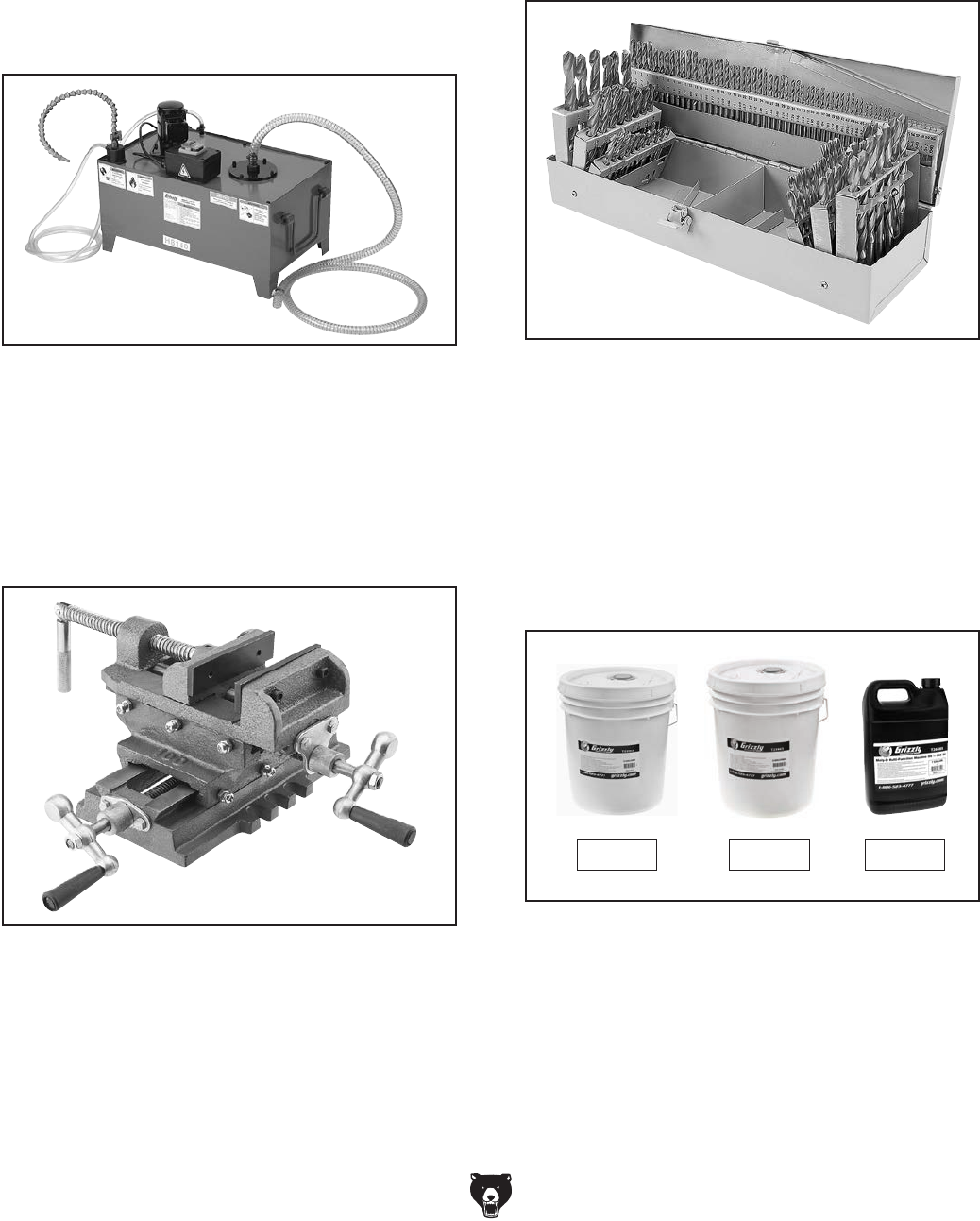
Figure 30. Model G3658 115-Pc. Drill Bit Set.
G3658—Tin-Coated 115-Pc. Drill Bit Set
Titanium nitride-coated bits last up to six times as
long as uncoated bits. This 115-piece set features
29 fractional bits, from 1⁄6" to 1⁄2" in increments
of 1⁄64", letter bits from A–Z, and 60 number bits.
Housed in a rugged steel case.
T23962—ISO 68 Moly-D Way Oil, 5 gal.
T23963—ISO 32 Moly-D Machine Oil, 5 gal.
T26685—ISO 32 Moly-D Machine Oil, 1 gal.
Moly-D oils are some of the best we've found for
maintaining the critical components of machinery
because they tend to resist run-off and maintain
their lubricity under a variety of conditions—as
well as reduce chatter or slip. Buy in bulk and
save with 5-gallon quantities.
Figure 31. ISO 68 and ISO 32 machine oil.
T23962 T23963 T26685
H8140—7 Gal. Coolant Tank System
Add this complete 7 Gallon Coolant Tank System
to any metal cutting machine for efficient cutting,
reduced tool wear and better finishes. Includes
pump, switch, enclosed tank, coolant return hose
and flexible nozzle with magnetic base. Made in
an ISO 9001 factory. Pump motor 1⁄16 HP, 110V;
maximum flow 3.17 gallons per minute; maximum
capacity 7 gallons.
Figure 28. Model H8140 7-Gallon Coolant Tank
System.
G1064—Cross-Sliding Vise
This vise features an exclusive slide bar to prevent
the jaws from tilting up or sideways when tighten-
ing. Adjustable gibs take up any slack on both top
and bottom slides. Use this vise on your drill press
for cutting keyways and doing light milling jobs.
Figure 29. Model G1064 Cross-Sliding Vise.
Model G0779 (Mfd. Since 09/14) -29-
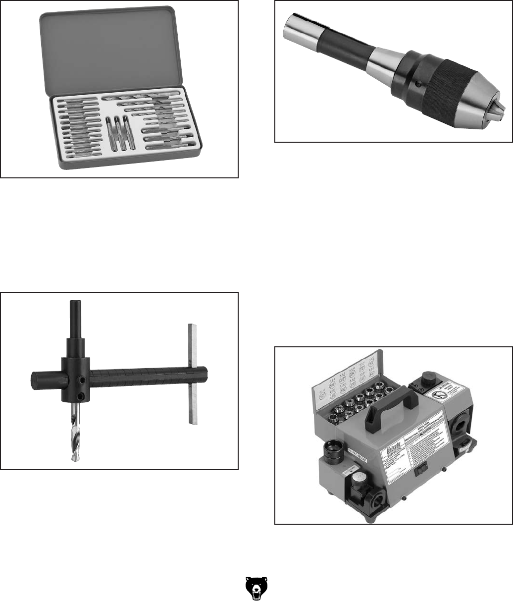
H7819—Drill & Tap HSS 24-Pc. Set
Our new High Speed Steel Tap and Drill Set
comes supplied with 6 of the most commonly
used coarse thread sizes. What's more, each size
has taps with plug, bottoming and taper grinds
allowing you to choose the right tap for any job.
The set includes the following tap sizes and corre-
sponding drill bits: 8-32 & #29, 10-24 & #25, 1⁄4"-20
& #7, 5⁄16"-18 & F, 3⁄8"-16 & 5⁄16" and 1⁄2"-13 & 27⁄64".
Figure 32. H7819 Drill & Tap HSS 24-Pc. Set.
T10169—Adjustable Circle Cutter
Produce precision circles in sheet metal, brass,
wood, plastic, aluminum, and soft steel with this
adjustable circle cutter. The diameter is adjust-
able up to 8" and includes HSS center and drill bit
and double-ended tool bit.
Figure 33. Model T10169 Adjustable Circle
Cutter.
H8263—1⁄2" x R-8 Keyless Chuck with Integral
Shank
Precision, Keyless Drill Chucks have integral
shanks to fit a variety of spindles including Morse
taper, R-8 and Cat 40. Each chuck has a knurled
grip for plenty of torque and if that’s not enough,
they are spanner wrench compatible. (Spanner
wrench not included.) Made in an ISO 9001 certi-
fied factory.
Figure 34. Model H8263 Precision Keyless Drill
Chuck.
H8203—Professional Drill Bit Sharpening
Machine (For Bits 1⁄8"–1⁄2" in Diameter)
This precision made Drill Bit Sharpening Machine
is so simple to use, anyone can sharpen dull,
smaller bits in three easy steps. Just set the drill
bit in the collet, grind the taper relief angle, then
grind the web thinning angle to reduce the center
point width. It features a depth adjustment gauge,
tapered diamond wheel, 90°–140° angle setting
adjustment, and built-in collet tray. Collet sizes
include 1⁄8", 5⁄32", 3⁄16", 1⁄4", 9⁄32", 5⁄16", 3⁄8", 25⁄64", 7⁄16",
15⁄32", and 1⁄2". Patented in the US!
Figure 35. Model H8203 Professional Drill Bit
Sharpening Machine.
-30- Model G0779 (Mfd. Since 09/14)
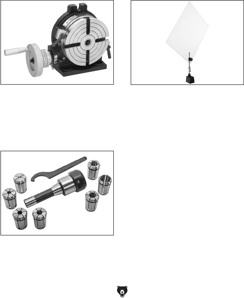
G1049—Combination Rotary Table - 6"
Use this 6" Rotary Table for circular cutting, angle
setting, boring and spot facing. Table surface and
rotating parts are ground for smooth operation.
Table is a solid Meehanite casting offering stabil-
ity and assured accuracy. Ratio on all models is
90-to-1 or 4 degrees per hand-wheel revolution.
Figure 36. Model G1049 Combination Rotary
Table 6".
Figure 38. Magnetic base with eye shield.
H2942—Magnetic Base w/Eye Shield 8" x 10"
H2943—Magnetic Base w/Eye Shield 12" x 16"
Need a shield? This is just the thing for setting up
extra protection. Powerful magnetic base allows
placing the shield just about anywhere and the
ball and socket joint allows a large range of posi-
tioning choices.
T26688—R-8 Quick Change Collet 8-Pc. Set
These collets are hardened and ground for maxi-
mum holding power and ultra precision. Threaded
fro 7⁄16"-20 draw bars, this set has a maximum run-
out of 0.001". Set includes collect chuck, 1⁄4", 5⁄16",
3⁄8", 1⁄2", 5⁄8", 3⁄4", and 1" collets, spanner wrench,
and moulded plastic case.
Figure 37. T26688 R-8 Quick Change Collet
8 pc. Set

Model G0779 (Mfd. Since 09/14) -31-
SECTION 6: MAINTENANCE
For optimum performance from your machine,
follow this maintenance schedule and refer to any
specific instructions given in this section.
Daily Check
• Check/repair loose mounting bolts or fasten-
ers.
• Check/repair worn or damaged wires.
• Check/repair damaged tooling.
• Clean debris and built-up grime off of machine.
• Check/resolve any other unsafe condition.
Every 8 Hours of Operation:
• Check/add headstock oil (Page 32).
• Lubricate column, racks, and quill (Page 33).
Every 90 Hours of Operation:
• Lubricate quill rack and pinion (Page 33).
Every 180 Days of Operation:
• Change headstock oil (Page 32).
Schedule
To reduce risk of shock or
accidental startup, always
disconnect machine from
power before adjustments,
maintenance, or service.
Lubrication
Cleaning &
Protecting
Sawdust, wood chips, and metal chips left on the
machine will invite oxidation and a gummy residue
buildup around the moving parts. Use a brush and
shop vacuum to remove chips and debris from the
working surfaces of the mill. Never blow off the
mill with compressed air, as this will force metal
chips deep into the mechanisms and may cause
injury to yourself or bystanders.
Remove any rust build-up from unpainted cast
iron surfaces of your drill press and treat with a
non- staining lubricant after cleaning.
Keep unpainted cast iron surfaces rust-free with
regular applications of ISO 68 way oil (see Page
28 for offerings from Grizzly).
An essential part of lubrication is cleaning the
components before lubricating them.
This step is critical because grime and chips build
up on lubricated components, which makes them
hard to move. Simply adding more lubricant will
not result in smooth moving parts.
Clean all exterior components in this section with
mineral spirits, shop rags, and brushes before
lubricating.
DISCONNECT MACHINE FROM POWER
BEFORE PERFORMING LUBRICATION!
NOTICE
Follow reasonable lubrication practices as
outlined in this manual. Failure to do so
could lead to premature failure of your
machine and will void the warranty.
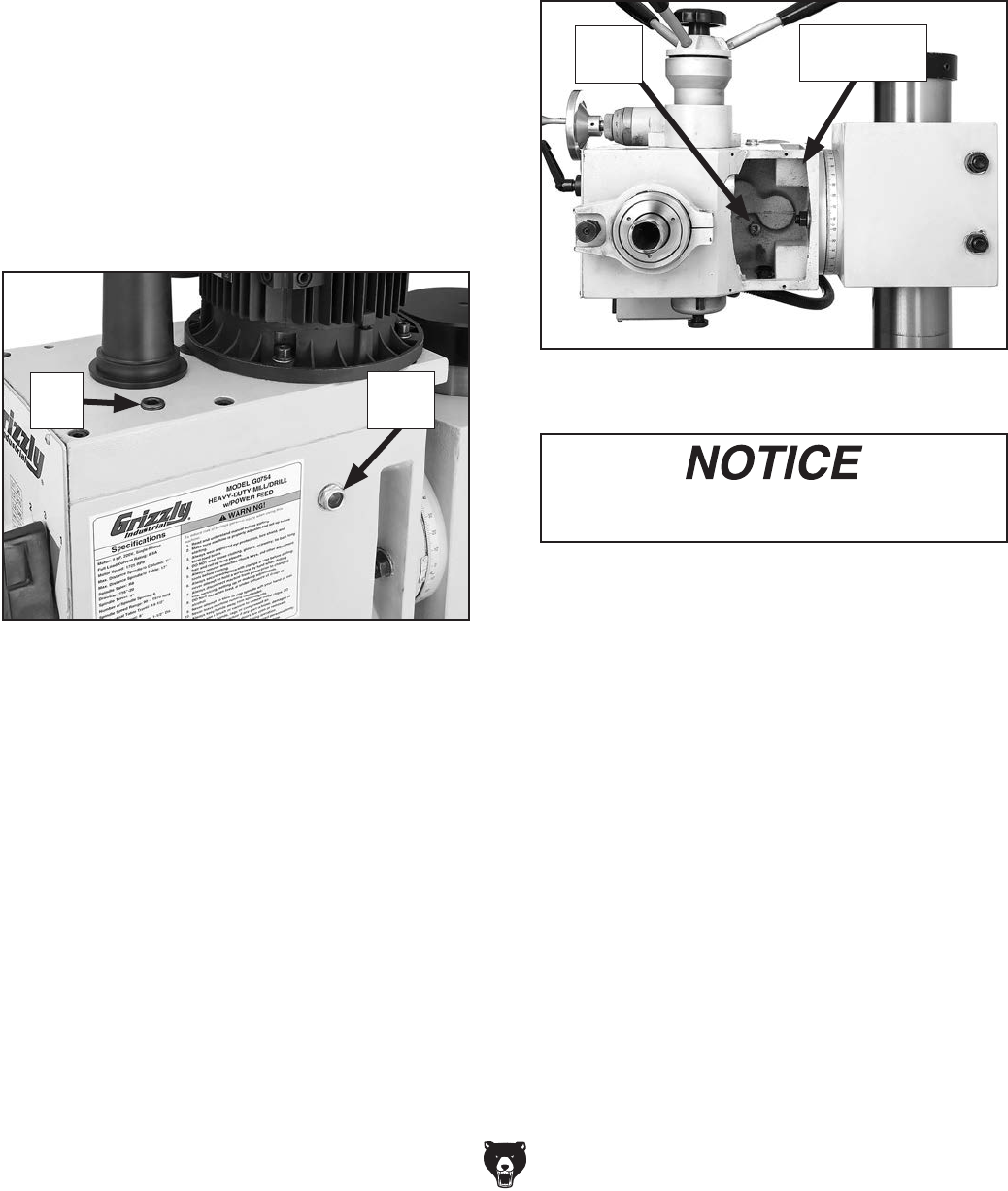
-32- Model G0779 (Mfd. Since 09/14)
For the quill, table, and column, an occasional
application of light machine oil is all that is neces-
sary. Before applying lubricant, clean off any dust
or metal chips.
Your goal is to achieve adequate lubrication. Too
much lubrication will attract dirt and dust. Various
parts of your machine could lose their freedom of
movement as a result.
Headstock Reservoir
Oil Type ......Model T23963 or ISO 32 Equivalent
Oil Amount ................................................ 43⁄4 Qt.
Check/Add Frequency ........8 Hours of Operation
Change Frequency ..................... Every 180 Days
The headstock has the proper amount of oil when
the sight glass is halfway full (see Figure 39).
Tools Needed Qty
Hex Wrench 2.5mm ........................................... 1
Hex Wrench 8mm .............................................. 1
Drain Pan (2-Gallon or Larger) .......................... 1
To change headstock oil:
1. Run spindle at 670 RPM for approximately 10
minutes to warm headstock oil.
2. DISCONNECT MACHINE FROM POWER!
3. Remove fill plug (see Figure 39).
Figure 39. Location of headstock oil sight glass
and fill plug.
Sight
Glass
Fill
Plug
4. Place drain pan on table under headstock.
5. Remove cover plate from bottom of head-
stock (see Figure 40).
6. Remove drain plug (see Figure 40) from
underneath headstock and allow oil to drain
into pan.
Figure 40. Headstock drain plug
(headstock tilted 90° for clarity).
Drain
Plug
Follow federal, and state, and local require-
ments for proper disposal of used oil.
7. Replace drain plug.
8. Add oil until sight glass is halfway full, then
replace fill plug and cover plate.
9. Clean up any spilled oil to prevent slipping
hazards.
Cover Plate
Removed
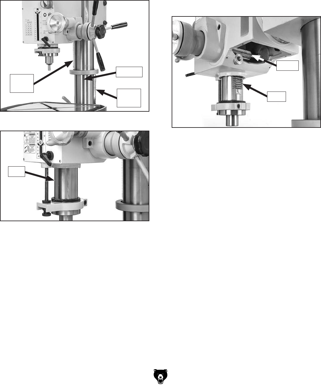
Model G0779 (Mfd. Since 09/14) -33-
Figure 41. Column and racks.
Column, Racks, & Quill
Oil Type ......Model T23962 or ISO 68 Equivalent
Oil Amount ............................................Thin Coat
Lubrication Frequency ...........8 Hrs. of Operation
Refer to Figures 41–42 to identify each compo-
nent to lubricate.
Figure 42. Outside surface of quill.
Quill
Use the component controls to access all sur-
faces, then clean them with mineral spirits, shop
rags, and, where appropriate, brushes.
When dry, apply a thin coat of oil to the surfaces.
Use clean brushes to apply oil to the grooves of
the column rack. Move each component through
the entire path of travel several times to distribute
the lubricant.
Note: Take care not to remove the quill rack
grease without re-applying it.
Quill Rack & Pinion
Oil Type ................ NLGI#2 Grease or Equivalent
Oil Amount ............................................Thin Coat
Lubrication Frequency .........90 Hrs. of Operation
Move the quill up and down to gain full access
to the quill rack and pinion (see Figure 43), then
clean the teeth with mineral spirits, shop rags, and
a brush.
When dry, use a brush to apply a thin coat of
grease to the teeth, then raise/lower the quill sev-
eral times to distribute the grease.
Note: Re-apply oil to the quill smooth outside
surface that was removed during the cleaning
process.
Figure 43. Quill rack and pinion.
Pinion
Rack
Column
Lower
Rack
Upper
Rack

-34- Model G0779 (Mfd. Since 09/14)
Review the troubleshooting and procedures in this section if a problem develops with your machine. If you
need replacement parts or additional help with a procedure, call our Technical Support.
Note: Please gather
the serial number and manufacture date of your machine before calling.
SECTION 7: SERVICE
Troubleshooting
Symptom Possible Cause Possible Solution
Machine does not
start or a breaker
trips.
1. Incorrect power supply voltage or incoming
wire connections.
2. Power supply circuit breaker tripped or fuse
blown.
3. Motor wires connected incorrectly.
4. Wiring open/has high resistance.
5. Start capacitor at fault.
6. Spindle rotation switch at fault.
7. Centrifugal switch/contact points at fault.
8. Motor at fault.
1. Ensure correct power supply voltage and incoming
wire connections.
2. Ensure circuit is sized correctly and free of shorts.
Reset circuit breaker or replace fuse.
3. Correct motor wiring connections.
4. Check/fix broken, disconnected, or corroded wires.
5. Test/replace.
6. Test/replace switch.
7. Adjust/replace centrifugal switch/contact points if
available.
8. Test/repair/replace.
Machine stalls or is
underpowered.
1. Machine undersized for task.
2. Wrong workpiece material (metal).
3. Motor overheated.
4. Motor wired incorrectly.
5. Plug/receptacle at fault.
6. Gearbox at fault.
7. Run capacitor at fault.
8. Centrifugal switch/contact points at fault.
9. Motor bearings at fault.
10. Spindle rotation switch at fault.
1. Use correct cutter/bit; reduce feed rate; reduce
spindle RPM; use coolant if possible.
2. Use correct type/size of metal.
3. Clean motor, let cool, and reduce workload.
4. Wire motor correctly.
5. Test for good contacts/correct wiring.
6. Select appropriate gear ratio; replace broken or
slipping gears.
7. Test/repair/replace.
8. Adjust/replace centrifugal switch or contact plate.
9. Test/repair/replace.
10. Test/replace switch.
Machine has
vibration or noisy
operation.
1. Motor or component loose.
2. Chuck or cutter at fault.
3. Motor fan rubbing on fan cover.
4. Motor mount loose/broken.
5. Machine incorrectly mounted/secured to
floor.
6. Motor or spindle bearings at fault.
7. Centrifugal switch is at fault.
1. Inspect/replace damaged bolts/nuts, and retighten
with thread locking fluid.
2. Replace unbalanced chuck; replace/resharpen
cutter; use correct feed rate.
3. Fix/replace fan cover; replace loose/damaged fan.
4. Tighten/replace.
5. Tighten mounting bolts; relocate/shim machine.
6. Test by rotating shaft; rotational grinding/loose shaft
requires bearing replacement.
7. Replace.
Motor & Electrical

Model G0779 (Mfd. Since 09/14) -35-
Symptom Possible Cause Possible Solution
Tool loose in spindle. 1. Tool is not fully drawn up into spindle taper.
2. Debris on tool or in spindle taper
3. Taking too big of a cut.
1. Tighten drawbar.
2. Clean tool and spindle taper.
3. Lessen depth of cut and allow chips to clear.
Breaking tools. 1. Spindle speed/feed rate is too fast.
2. Tool is too small.
3. Tool getting too hot.
4. Taking too big of a cut.
5. Spindle extended too far down.
1. Set spindle speed correctly or use slower feed rate
(Page 25).
2. Use larger tool.
3. Use coolant or oil for appropriate application.
4. Lessen depth of cut and allow chips to clear.
5. Fully retract spindle and lower headstock. This
increases rigidity (Page 21).
Workpiece or tool
vibrates or chatters
during operation.
1. Table locks not tight.
2. Workpiece not secure.
3. Spindle speed/feed rate is too fast.
4. Spindle or quill extended too far down.
5. Quill lock lever not tight.
1. Tighten table locks (Page 20).
2. Properly clamp workpiece on table.
3. Set spindle speed correctly (Page 25).
4. Fully retract spindle and lower headstock. This
increases rigidity (Page 21).
5. Tighten quill lock lever (Page 24).
Table is hard to
move.
1. Chips have loaded up on rack and pinion. 1. Frequently clean away chips that load up during
operations.
Headstock is hard to
raise.
1. Headstock lock nuts at fault.
2. Rack and pinion at fault or jammed with
grime/debris.
1. Loosen/replace lock nuts.
2. Fix/replace broken or loose parts; clean and
lubricate rack and pinion.
Bad surface finish. 1. Spindle speed is too fast.
2. Dull or incorrect cutting tool.
3. Wrong rotation of cutting tool.
4. Workpiece not secure.
5. Spindle extended too far down.
1. Set spindle speed correctly (Page 25).
2. Sharpen cutting tool or select one that better suits
the operation.
3. Check for proper cutting tool rotation.
4. Properly clamp workpiece on table.
5. Fully retract spindle and lower headstock. This
increases rigidity (Page 21).
Spindle overheats. 1. Drill operated at high speeds for extended
period.
1. Allow drill to cool.
Spindle does not
return to highest
position.
1. Poorly adjusted return spring.
2. Worn return spring.
1. Increase return spring tension (Page 36).
2. Replace return spring.
Depth stop pro-
ducing inaccurate
results.
1. Depth stop not calibrated. 1. Calibrate depth stop (Page 36).
Drill Press Operations
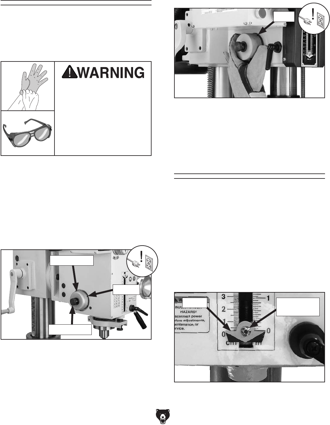
-36- Model G0779 (Mfd. Since 09/14)
Tensioning Return
Spring
3. Loosen thumb knob shown in Figure 44
2–3 turns (DO NOT completely remove
thumb knob).
To adjust spring tension:
1. DISCONNECT MACHINE FROM POWER!
2. PUT ON SAFETY GLASSES!
If the return spring should
come loose from the spring
cap and rapidly unwind,
laceration or impact inju-
ries could occur. Always
wear heavy leather gloves
and safety glasses when
adjusting the return spring
tension.
Figure 44. Spring tension components.
Thumb Knob
Spring Cover
Roll Pin
4. Wearing gloves, pull spring cover (Figure
45) out enough so notches just clear roll pin.
HOLD SPRING COVER TIGHTLY during this
step, or force of spring will cause cover to
spin out of your hands.
5. Rotate cover counterclockwise to increase
tension, then push cover back in to engage
roll pin with one of the notches, as shown in
Figure 45, then retighten thumb knob.
Notch
Figure 45. Example of adjusting spring tension
by rotating spring cover to engage next notch
with roll pin.
The spring tension for automatic quill recoil has
been pre-set at the factory. It should not need
adjustment under most normal circumstances. If
it does need adjustment, the spring housing is
located on the left side of the headstock.
Calibrating Depth
Stop
The depth stop can be calibrated to improve
accuracy. Make sure the spindle is retracted all
the way into the quill, then follow the steps below.
To calibrate depth stop:
1. Lower depth stop (see Figure 46) until point-
er reaches bottom of its travel.
2. Loosen button head cap screw shown in
Figure 46, and position pointer so its upper
edge aligns with zero, then re-tighten screw.
Figure 46. Calibrating depth stop.
Pointer Button Head
Cap Screw

Model G0779 (Mfd. Since 09/14) -37-
SHOCK HAZARD. Working on wiring that is con-
nected to a power source is extremely dangerous.
Touching electrified parts will result in personal
injury including but not limited to severe burns,
electrocution, or death. Disconnect the power
from the machine before servicing electrical com-
ponents!
MODIFICATIONS. Modifying the wiring beyond
what is shown in the diagram may lead to unpre-
dictable results, including serious injury or fire.
This includes the installation of unapproved after-
market parts.
WIRE CONNECTIONS. All connections must
be tight to prevent wires from loosening during
machine operation. Double-check all wires dis-
connected or connected during any wiring task to
ensure tight connections.
CIRCUIT REQUIREMENTS. You MUST follow
the requirements at the beginning of this manual
when connecting your machine to a power source.
WIRE/COMPONENT DAMAGE. Damaged wires
or components increase the risk of serious per-
sonal injury, fire, or machine damage. If you notice
that any wires or components are damaged while
performing a wiring task, replace those wires or
components.
MOTOR WIRING. The motor wiring shown in
these diagrams is current at the time of printing
but may not match your machine. If you find this
to be the case, use the wiring diagram inside the
motor junction box.
CAPACITORS/INVERTERS. Some capacitors
and power inverters store an electrical charge for
up to 10 minutes after being disconnected from
the power source. To reduce the risk of being
shocked, wait at least this long before working on
capacitors.
EXPERIENCING DIFFICULTIES. If you are expe-
riencing difficulties understanding the information
included in this section, contact our Technical
Support at (570) 546-9663.
Wiring Safety Instructions
The photos and diagrams
included in this section are
best viewed in color. You
can view these pages in
color at www.grizzly.com.
These pages are current at the time of printing. However, in the spirit of improvement, we may make chang-
es to the electrical systems of future machines. Compare the manufacture date of your machine to the one
stated in this manual, and study this section carefully.
If there are differences between your machine and what is shown in this section, call Technical Support at
(570) 546-9663 for assistance BEFORE making any changes to the wiring on your machine. An updated
wiring diagram may be available. Note: Please gather the serial
number and manufacture date of your
machine before calling. This information can be found on the main machine label.
SECTION 8: WIRING
machine
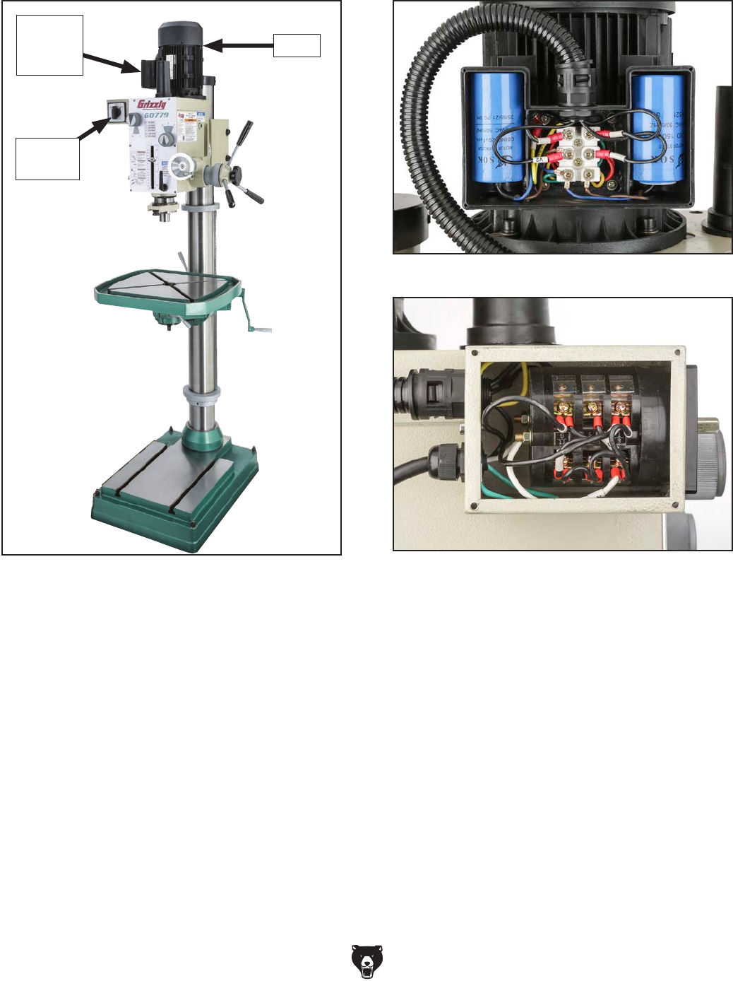
-38- Model G0779 (Mfd. Since 09/14)
Electrical Components
Figure 47. Electrical component wiring overview.
Figure 48. Motor junction box wiring.
Figure 49. Switch box wiring.
Motor
Spindle
Switch
Motor
Junction
Box
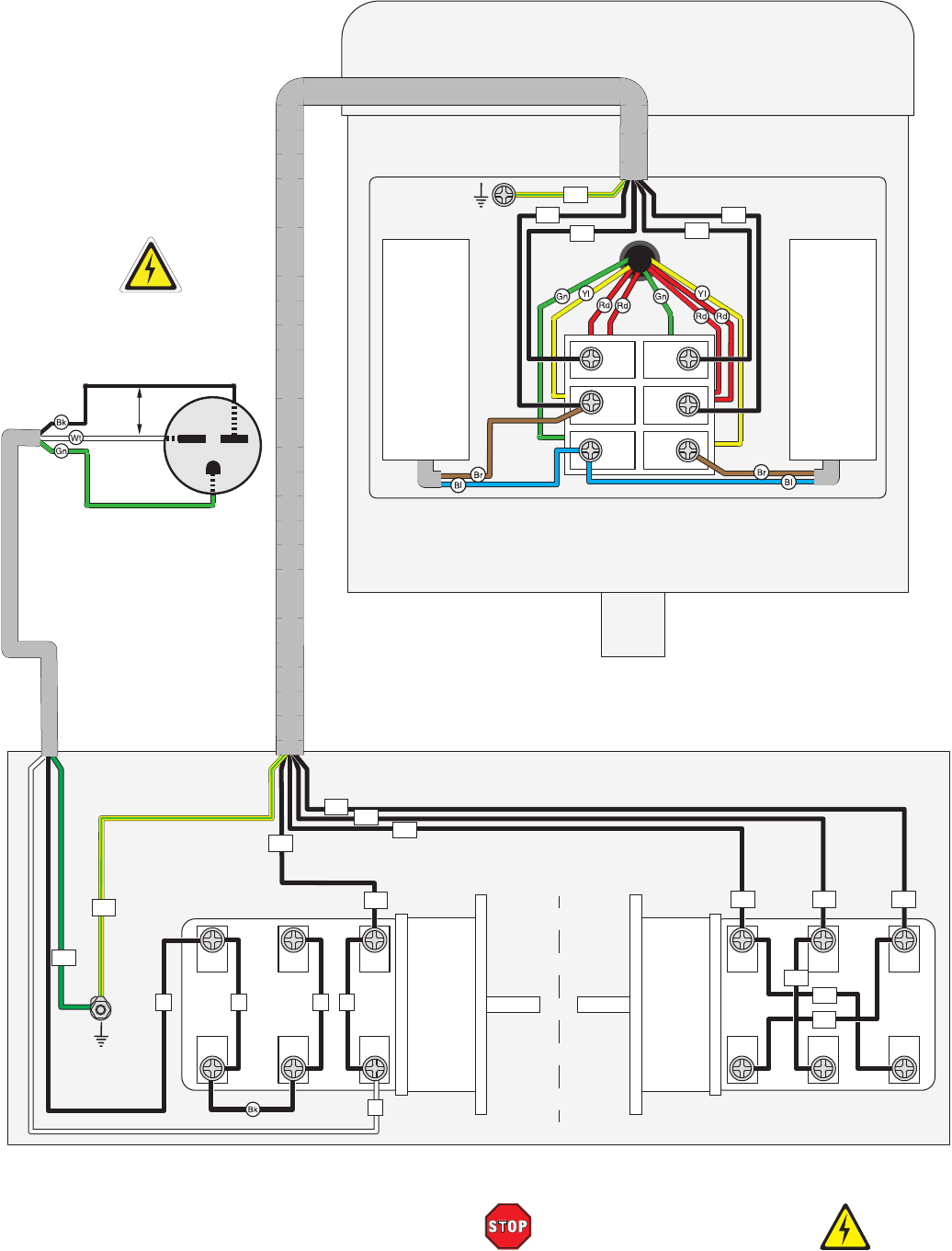
Model G0779 (Mfd. Since 09/14) -39-
READ ELECTRICAL SAFETY
ON PAGE 37!
Ground
9
11
5
CanSen
LW5D-16
7
1
3
2
4
6
8 12
10
Spindle Switch
Left
Side
Right
Side
L
V2
V2
V2
V1
V1
V1
U2
U2
U2
U1
U1
U1
V1 U2
V2W1
W2
Ground
PE
PE
PE
N
NL L
220V Motor
6-15 Plug
(Included)
Hot
Hot
Ground
220
VAC
G
U2
V1
U1
V2
Start
Capacitor
150MFD
250VAC
Run
Capacitor
20MFD
450VAC
Wiring Diagram
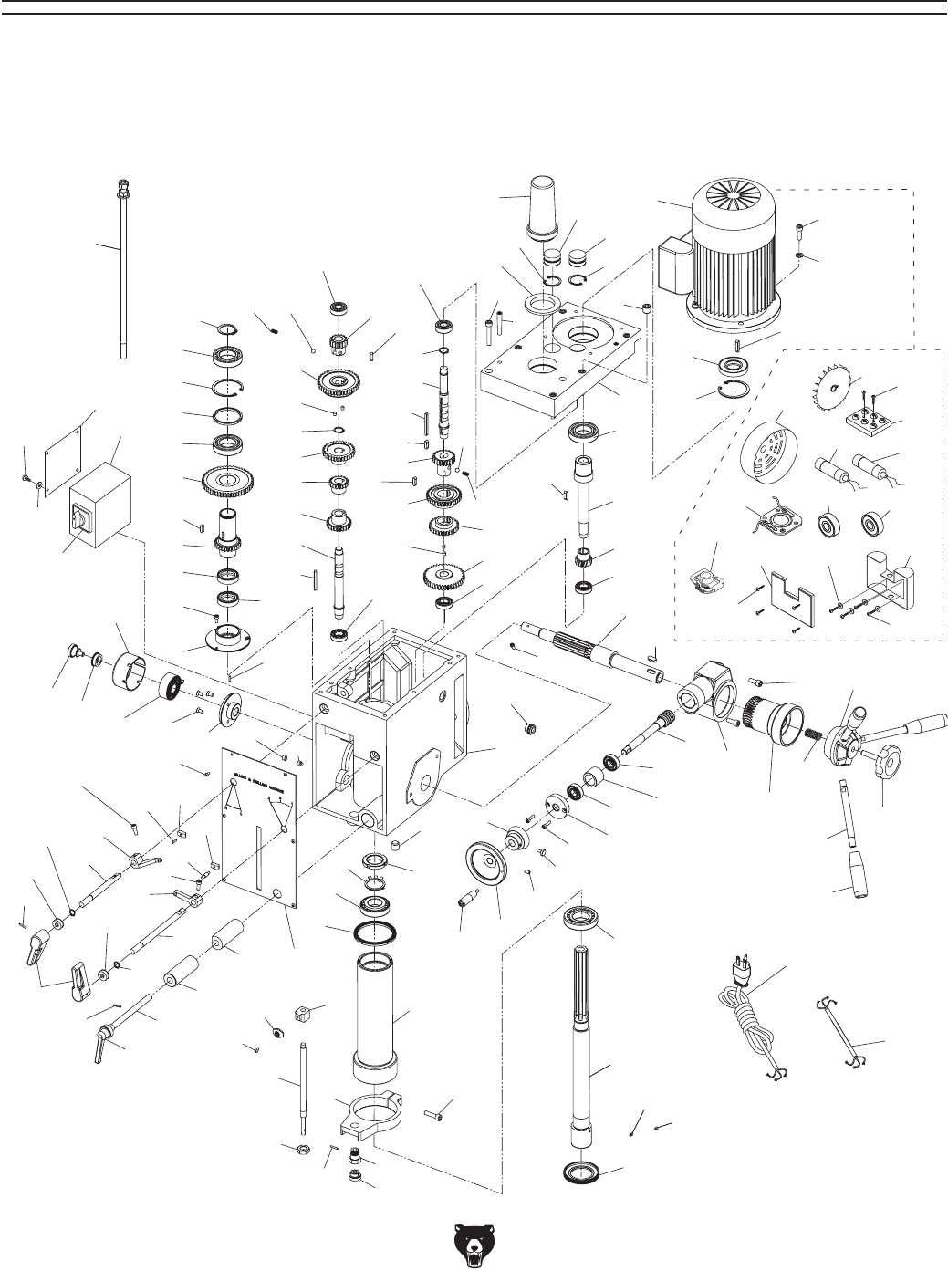
-40- Model G0779 (Mfd. Since 09/14)
1
2
3
4
4
3
6
57
58
29
73
29
59
23
51
28
27
26
30
29
18
13
14
19
19
11 7
8
9
36
36
40 39
51
49
48
43
41
41
47
46
45
50
44 35
43 32
33
38
40
39
34
37
42
31
100
83
102
77
95
82
89
84
91
92
88
78
36
81
36
79
103
90
96
93
94
22
68
67
56
69
53
65
66
70
64
62
71 63
61
60 72
74
54
55 126
127
10
15
16
85
101
99
87
86
97
98
111
104
113
110
109
112
21
20
115
115
112
116
118
113
114
117
106
107
105
108
21
24
17
25
75
76
80
119
5
6
12
28 28
35
64
7-2
7-1
7-6
7-5
7-4
7-3
7-7
7-9
7-8
7-10
7-13
7-15
7-12
7-11
7-14
122
121
125
123
124
120
Headstock
SECTION 9: PARTS
We do our best to stock replacement parts when possible, but we cannot guarantee that all parts shown
are available for purchase. Call (800) 523-4777 or visit www.grizzly.com/parts to check for availability.

Model G0779 (Mfd. Since 09/14) - 41-
REF PART # DESCRIPTION REF PART # DESCRIPTION
1 P0779001 HEADSTOCK CASTING 35 P0779035 GEAR 41T
2 P0779002 HEADSTOCK COVER 36 P0779036 BALL BEARING 6202ZZ
3 P0779003 INT RETAINING RING 62MM 37 P0779037 KEY 6 X 6 X 14
4 P0779004 INT RETAINING RING 35MM 38 P0779038 KEY 6 X 6 X 28
5 P0779005 FLANGED END CAP 39 P0779039 STEEL BALL 8MM
6 P0779006 OIL SEAL 45 X 35 X 10MM 40 P0779040 COMPRESSION SPRING
7 P0779007 MOTOR 2HP 220V 1-PH 41 P0779041 EXT RETAINING RING 18MM
7-1 P0779007-1 MOTOR FAN COVER 42 P0779042 KEY 5 X 5 X 50
7-2 P0779007-2 MOTOR FAN 43 P0779043 SET SCREW M6-1 X 12
7-3 P0779007-3 PHLP HD SCR M4-.7 X 16 44 P0779044 SPINDLE SHAFT
7-4 P0779007-4 MOTOR TERMINAL BLOCK 45 P0779045 GEAR 25T
7-5 P0779007-5 CONTACT PLATE 46 P0779046 GEAR 18T
7-6 P0779007-6 S CAPACITOR 150M 250V 1-5/8 X 3 47 P0779047 GEAR 32T
7-7 P0779007-7 R CAPACITOR 20M 450V 1-5/8 X 3-1/4 48 P0779048 GEAR 43T
7-8 P0779007-8 CENTRIFUGAL SWITCH 49 P0779049 GEAR 16T
7-9 P0779007-9 BALL BEARING 6205ZZ (FRONT) 50 P0779050 KEY 5 X 5 X 50
7-10 P0779007-10 BALL BEARING 6205ZZ (REAR) 51 P0779051 KEY 6 X 6 X 18
7-11 P0779007-11 CAPACITOR BOX COVER 53 P0779053 QUILL
7-12 P0779007-12 FLAT WASHER 4MM 54 P0779054 SPINDLE
7-13 P0779007-13 CAPACITOR BOX 55 P0779055 TAPERED ROLLER BEARING 30207 P5
7-14 P0779007-14 TAP SCREW M3-.5 X 10 56 P0779056 TAPERED ROLLER BEARING 30206 P5
7-15 P0779007-15 PHLP HD SCR M4-.7 X 10 57 P0779057 SPLINED SLEEVE
8 P0779008 CAP SCREW M8-1.25 X 25 58 P0779058 GEAR 53T
9 P0779009 FLAT WASHER 8MM 59 P0779059 EXT RETAINING RING 35MM
10 P0779010 HEADSTOCK FACE PLATE 60 P0779060 DEPTH ROD MOUNT
11 P0779011 DRAWBAR CAP 61 P0779061 CYLINDRICAL BOLT M16-2 X 10
12 P0779012 DRAWBAR CAP RUBBER SEAL 62 P0779062 HEX NUT M16-2 THIN
13 P0779013 CAP SCREW M8-1.25 X 45 63 P0779063 DEPTH ROD KNURLED KNOB
14 P0779014 TAPER PIN 8 X 40 64 P0779064 DEPTH ROD
15 P0779015 SET SCREW M10-1.5 X 10 DOG-PT 65 P0779065 DEPTH ROD STOP BLOCK
16 P0779016 SET SCREW M10-1.5 X 8 66 P0779066 DEPTH POINTER
17 P0779017 KEY 6 X 6 X 28 67 P0779067 LOCK WASHER 30MM
18 P0779018 OIL FILL PLUG 3/8" 68 P0779068 SPANNER NUT M30-1.5
19 P0779019 HEADSTOCK COVER PLUG 69 P0779069 QUILL SEAL (RUBBER)
20 P0779020 SPINDLE SPEED LEVER 70 P0779070 BUTTON HD CAP SCR M4-.7 X 8
21 P0779021 ROLL PIN 3 X 18 71 P0779071 ROLL PIN 3 X 18
22 P0779022 OIL DRAIN PLUG 3/8" 72 P0779072 CAP SCREW M8-1.25 X 30
23 P0779023 CAP SCREW M5-.8 X 10 73 P0779073 SPACER
24 P0779024 BUTTON HD CAP SCR M4-.7 X 8 74 P0779074 SPINDLE END CAP
25 P0779025 OIL SIGHT GLASS M18-1.5 75 P0779075 SET SCREW M5-.8 X 6
26 P0779026 DRIVE SHAFT 76 P0779076 SET SCREW M5-.8 X 4
27 P0779027 GEAR 14T 77 P0779077 WORM GEAR HOUSING
28 P0779028 BALL BEARING 6003ZZ 78 P0779078 WORM SHAFT
29 P0779029 BALL BEARING 6007ZZ 79 P0779079 WORM SHAFT END BRACKET
30 P0779030 KEY 5 X 5 X 25 80 P0779080 SET SCREW M6-1 X 12
31 P0779031 IDLER SHAFT 81 P0779081 SPACER
32 P0779032 GEAR 29T 82 P0779082 WORM GEAR
33 P0779033 GEAR 35T 83 P0779083 PINION SHAFT
34 P0779034 GEAR 21T 84 P0779084 LEVER HUB
Headstock Parts List

-42- Model G0779 (Mfd. Since 09/14)
REF PART # DESCRIPTION REF PART # DESCRIPTION
85 P0779085 SPRING BASE 107 P0779107 OUTSIDE LOCK PLUNGER
86 P0779086 SPRING COVER 108 P0779108 ADJUSTABLE HANDLE
87 P0779087 FLAT COILED SPRING 109 P0779109 SPEED RANGE SHIFT SHAFT
88 P0779088 KNOB BOLT M10-1.5 X 45 110 P0779110 SPEED RANGE SHIFT LEVER
89 P0779089 COMPRESSION SPRING 111 P0779111 SPEED RANGE SHIFT FORK
90 P0779090 FINE DOWNFEED GRADUATED DIAL 112 P0779112 EXT RETAINING RING 12MM
91 P0779091 STUD-UDE M12-1.75 X 145, 15, 20 113 P0779113 CAP SCREW M6-1 X 14
92 P0779092 TAPERED HANDLE M12-1.75, 98L 114 P0779114 SHIFT ROD
93 P0779093 HANDWHEEL 100MM DIA. 115 P0779115 OIL SEAL 12 X 22 X 8
94 P0779094 HANDWHEEL HANDLE M6-1 X 10, 65L 116 P0779116 SPEED SHIFT SHAFT
95 P0779095 CAP SCREW M8-1.25 X 25 117 P0779117 SPEED SHIFT FORK
96 P0779096 KNURLED THUMB SCREW M5-.8 X 12 118 P0779118 SPEED SHIFT LEVER
97 P0779097 KNOB BUSHING 119 P0779119 OIL SEAL 35 X 62 X 10
98 P0779098 KNURLED THUMB SCREW M8-1.25 X 12 120 P0779120 PHLP HD SCR M4-.7 X 6
99 P0779099 FLAT HD CAP SCR M6-1 X 12 121 P0779121 SWITCH BOX COVER
100 P0779100 PHLP HD SCR M5-.8 X 12 122 P0779122 SWITCH BOX
101 P0779101 DOWEL PIN 3 X 12 123 P0779123 ROTARY SWITCH (LEFT, STOP, RIGHT)
102 P0779102 KEY 8 X 8 X 20 124 P0779124 FLAT WASHER 4MM
103 P0779103 CAP SCREW M5-.8 X 20 125 P0779125 DRAWBAR 7/16-20
104 P0779104 ROLL PIN 3 X 15 126 P0779126 POWER CORD 14G 3W 80" 6-15
105 P0779105 LOCK LEVER SHAFT 127 P0779127 MOTOR CORD 14G 3W 12"
106 P0779106 INSIDE LOCK PLUNGER
Headstock Parts List (Cont.)
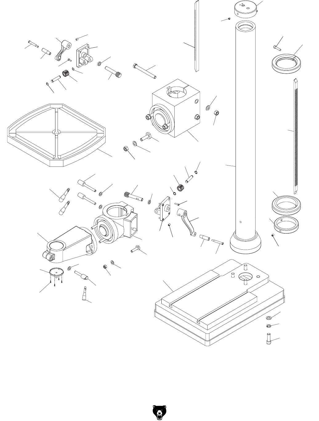
Model G0779 (Mfd. Since 09/14) -43-
Column
201
202
203
204
207
208
213
210
226
216
215
217
219
220
221
222
223
255
254 224
225
227
240
247
241
243
245
244
243
250
246
248
231
230
251
252
253
229
244
245
249
249
205
209
211
212
214
218
242
206
241
242
240
243
243
250
247
246
248

-44- Model G0779 (Mfd. Since 09/14)
Column Parts List
REF PART # DESCRIPTION REF PART # DESCRIPTION
201 P0779201 BASE 224 P0779224 PIVOT LOCK HUB M12-1.75 X 60
202 P0779202 COLUMN 225 P0779225 LEVER HANDLE M10-1.5 X 8, 75L
203 P0779203 TABLE ARM BRACKET 226 P0779226 RACK RING BASE
204 P0779204 TABLE BRACKET 227 P0779227 SET SCREW M10-1.5 X 16
205 P0779205 TABLE 229 P0779229 HEX BOLT M16-2 X 190
206 P0779206 HEAD ELEVATION GEAR HOUSING 230 P0779230 FLAT WASHER 16MM
207 P0779207 COLUMN CAP 231 P0779231 HEX NUT M16-2
208 P0779208 RACK GUIDE RING 240 P0779240 ELEVATION CRANK BRACKET
209 P0779209 RACK (HEAD ELEVATION) 241 P0779241 WORM GEAR
210 P0779210 RACK (TABLE ELEVATION) 242 P0779242 SPACER
211 P0779211 RACK RING 243 P0779243 EXT RETAINING RING 14MM
212 P0779212 SET SCREW M10-1.5 X 10 244 P0779244 HELICAL GEAR 15T
213 P0779213 CAP SCREW M10-1.5 X 40 245 P0779245 SHAFT
214 P0779214 FLAT WASHER 16MM 246 P0779246 ELEVATION CRANK
215 P0779215 LOCK WASHER 16MM 247 P0779247 SET SCREW M10-1.5 X 12
216 P0779216 HEX BOLT M16-2 X 50 248 P0779248 CRANK HANDLE 75MM
217 P0779217 FLAT WASHER 12MM 249 P0779249 SHOULDER SCREW M10-1.5 X 10, 12 X 68
218 P0779218 TABLE LOCK HUB M12-1.75 X 95 250 P0779250 CAP SCREW M6-1 X 20
219 P0779219 TABLE LOCK HANDLE M10-1.5 X 12, 115L 251 P0779251 T-BOLT M14-2 X 55
220 P0779220 T-BOLT M12-1.75 X 45 252 P0779252 FLAT WASHER 14MM
221 P0779221 FLAT WASHER 12MM 253 P0779253 HEX NUT M14-2
222 P0779222 HEX NUT M12-1.75 254 P0779254 CAP SCREW M6-1 X 12
223 P0779223 FLAT WASHER 12MM 255 P0779255 COOLANT DRAIN
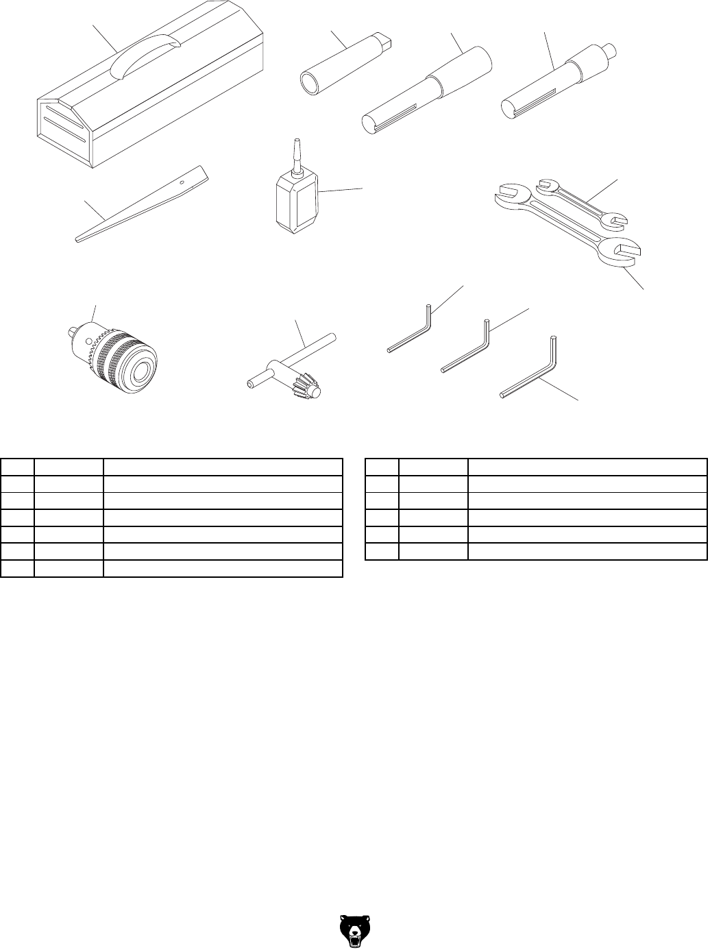
Model G0779 (Mfd. Since 09/14) -45-
Accessories
301 302 303 304
305
306
307
308
309
310
311
312 313
REF PART # DESCRIPTION REF PART # DESCRIPTION
301 P0779301 TOOLBOX 308 P0779308 HEX WRENCH 4MM
302 P0779302 SPINDLE ADAPTER MT3-MT2 309 P0779309 HEX WRENCH 3MM
303 P0779303 SPINDLE SLEEVE R8-MT3 310 P0779310 DRILL CHUCK KEY 5/16" STD 11T SD-5/8"
304 P0779304 DRILL CHUCK ARBOR R8-B16 311 P0779311 DRILL CHUCK 1-13MM B16
305 P0779305 WRENCH 17 X 19MM OPEN-ENDS 312 P0779312 DRIFT KEY
306 P0779306 WRENCH 22 X 24MM OPEN-ENDS 313 P0779313 BOTTLE FOR OIL
307 P0779307 HEX WRENCH 5MM
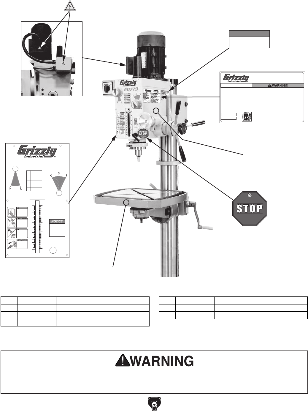
-46- Model G0779 (Mfd. Since 09/14)
Labels
G0779
(12/05/14)
G0779 Machine Labels A • Label is actual size
• Label must be made of
oil-resistant material
WARNING
COPYRIGHT © GRIZZLY INDUSTRIAL, INC.
FOR GRIZZLY MACHINES ONLY! DO NOT REPRODUCE OR CHANGE THIS ARTWORK
WITHOUT WRITTEN APPROVAL! Grizzly will not accept labels changed without approval. If
artwork changes are required, contact us immediately at manuals@grizzly.com.
PANTONE 151 C or RAL 2005
COLOR CODES
NOTICE PANTONE 3005 C or RAL 5005 GRIZZLY GREEN PANTONE 568C
GRIZZLY LOGO RED PANTONE 711C or RAL 3020
340 x 190 mm
L2
L1
210 RPM
90 RPM
Change spindle
speed or rotation
direction ONLY
when spindle is
completely
stopped.
5
4
3
2
1
0
NOTICE
Do not exceed gearbox oil level
above red dot in center of oil
site glass below.
REFER TO
OWNER’S MANUAL
FOR OIL TYPE AND
AMOUNT.
CHECK OIL
LEVELS BEFORE USING!
DANGER PANTONE 485 C or RAL 3001
PANTONE 151 C or RAL 2005
WARNING
CAUTION PANTONE 109 C
GRIZZLY LOGO RED PANTONE 711C or RAL 3020
COLOR CODES
NOTICE PANTONE 3005 C or RAL 5005
COPYRIGHT © GRIZZLY INDUSTRIAL, INC.
FOR GRIZZLY MACHINES ONLY! DO NOT REPRODUCE OR CHANGE THIS ARTWORK
WITHOUT WRITTEN APPROVAL! Grizzly will not accept labels changed without approval.
artwork changes are required, contact us immediately at manuals@grizzly.com
17 x 19mm
54 x 54mm
34.5 x 80mm
402
G0779 Machine Labels B
(12/05/14)
• 1:1 Sizing (Labels are
actual size)
• Labels must be made of
chemical-resistant material
NOTICE
Do not exceed gearbox oil level
above red dot in center of oil
site glass below.
REFER TO
OWNER’S MANUAL
FOR OIL TYPE AND
AMOUNT.
CHECK OIL
LEVELS BEFORE USING!
Motor: 2 HP, 220V, Single-Phase, 60 Hz, 8.6A
Motor Speed: 1720 RPM
Swing: 23-3/8"
Distance Spindle to Column: 11-11/16"
Distance Spindle to Table: 26-1/2"
Spindle Taper: R-8
Spindle Travel: 5"
Number of Spindle Speeds: 6
Spindle Speed Range: 90 – 1970 RPM
Vertical Table Travel: 24-3/8"
Table Swivel Around Column: 360˚
Drilling Capacity Mild Steel: 1-1/4"
Gearhead Fluid Capacity: 4-3/4 qt.
(Grizzly #T23963 or ISO 32 Equivalent)
Weight: 706 lbs.
Specifications
MODEL G0779
HEAVY-DUTY 23" GEARHEAD
DRILL PRESS
Date
S/N
Mfd. for Grizzly in China
DANGER PANTONE 485 C or RAL 3001
PANTONE 151 C or RAL 2005
WARNING
CAUTION PANTONE 109 C
GRIZZLY LOGO RED PANTONE 711C or RAL 3020
COLOR CODES
NOTICE PANTONE 3005 C or RAL 5005
COPYRIGHT © GRIZZLY INDUSTRIAL, INC.
FOR GRIZZLY MACHINES ONLY! DO NOT REPRODUCE OR CHANGE THIS ARTWORK
WITHOUT WRITTEN APPROVAL! Grizzly will not accept labels changed without approval. If
artwork changes are required, contact us immediately at manuals@grizzly.com.
To reduce the risk of serious injury when using this machine:
1. Read and understand owner’s manual before operating.
2. Always wear approved safety glasses.
3. Only plug power cord into a grounded outlet.
4. Disconnect power before setting up or servicing.
5. Avoid entanglement with spindle—tie back long hair, roll up long sleeves,
and DO NOT wear loose clothing, gloves, or jewelry.
6. Properly set up machine before starting.
7. Keep all guards and covers in place during operation.
8. Clamp workpiece to table to prevent rotation.
9. Avoid positioning hands where they could slip into rotating bits.
10. Always remove chuck keys and other tools before starting.
11. Never attempt to slow or stop spindle with hands or tools.
12. Use correct speeds for drilling accessories and workpiece.
13. Do not operate when tired or under influence of drugs or alcohol.
14. Do not expose to rain or use in wet locations.
15. Prevent unauthorized use by children or untrained users;
restrict access or disable machine when unattended.
106 x 175.5mm
17 x 19mm
54 x 54mm
34.5 x 80mm
403
404
G0779 Machine Labels B
(12/05/14)
NOTICE
Do not exceed gearbox oil level
above red dot in center of oil
site glass below.
REFER TO
OWNER’S MANUAL
FOR OIL TYPE AND
AMOUNT.
CHECK OIL
LEVELS BEFORE USING!
Motor: 2 HP, 220V, Single-Phase, 60 Hz, 8.6A
Motor Speed: 1720 RPM
Swing: 23-3/8"
Distance Spindle to Column: 11-11/16"
Distance Spindle to Table: 26-1/2"
Spindle Taper: R-8
Spindle Travel: 5"
Number of Spindle Speeds: 6
Spindle Speed Range: 90 – 1970 RPM
Vertical Table Travel: 24-3/8"
Table Swivel Around Column: 360˚
Drilling Capacity Mild Steel: 1-1/4"
Gearhead Fluid Capacity: 4-3/4 qt.
(Grizzly #T23963 or ISO 32 Equivalent)
Weight: 706 lbs.
Specifications
MODEL G0779
HEAVY-DUTY 23
DRILL PRESS
Date
S/N
Mfd. for Grizzly in China
GRIZZLY LOGO RED
COPYRIGHT © GRIZZLY INDUSTRIAL, INC.
FOR GRIZZLY MACHINES ONLY! DO NOT REPRODUCE OR CHANGE THIS ARTWORK
WITHOUT WRITTEN APPROVAL! Grizzly will not accept labels changed without approval.
artwork changes are required, contact us immediately at
To reduce the risk of serious injury when using this machine:
1. Read and understand owner’s manual before operating.
2. Always wear approved safety glasses.
3. Only plug power cord into a grounded outlet.
4. Disconnect power before setting up or servicing.
5. Avoid entanglement with spindle—tie back long hair, roll up long sleeves,
and DO NOT wear loose clothing, gloves, or jewelry.
6. Properly set up machine before starting.
7. Keep all guards and covers in place during operation.
8. Clamp workpiece to table to prevent rotation.
9. Avoid positioning hands where they could slip into rotating bits.
10. Always remove chuck keys and other tools before starting.
11. Never attempt to slow or stop spindle with hands or tools.
12. Use correct speeds for drilling accessories and workpiece.
13. Do not operate when tired or under influence of drugs or alcohol.
14. Do not expose to rain or use in wet locations.
15. Prevent unauthorized use by children or untrained users;
restrict access or disable machine when unattended.
17 x 19mm
54 x 54mm
34.5 x 80mm
405
H3
H2
H1
L3
1970 RPM
1180 RPM
670 RPM
345 RPM
13
12
11
10
9
8
7
6
5
4
3
2
1
0
cm in
To reduce risk of death
or serious injury, read
manual BEFORE using
machine.
To get a new manual, call
(800) 523-4777 or go to
www.grizzly.com.
WARNING!
INJURY/SHOCK
HAZARD!
Disconnect power
before adjustments,
maintenance, or
service.
WARNING!
ENTANGLEMENT
HAZARD!
Tie back long hair, roll up
long sleeves, and remove
loose clothing, jewelry, or
gloves to prevent getting
caught in moving parts.
Always wear
ANSI-approved safety
glasses and face shield
when using this
machine.
EYE/FACE INJURY
HAZARD!
407
406
NOTICE
Do not exceed gearbox oil level
above red dot in center of oil
site glass below.
REFER TO
OWNER’S MANUAL
FOR OIL TYPE AND
AMOUNT.
CHECK OIL
LEVELS BEFORE USING!
DANGER PANTONE 485 C or RAL 3001
PANTONE 151 C or RAL 2005
WARNING
CAUTION PANTONE 109 C
GRIZZLY LOGO RED PANTONE 711C or RAL 3020
COLOR CODES
NOTICE PANTONE 3005 C or RAL 5005
COPYRIGHT © GRIZZLY INDUSTRIAL, INC.
FOR GRIZZLY MACHINES ONLY! DO NOT REPRODUCE OR CHANGE THIS ARTWORK
WITHOUT WRITTEN APPROVAL! Grizzly will not accept labels changed without approval. If
artwork changes are required, contact us immediately at manuals@grizzly.com.
17 x 19mm
54 x 54mm
34.5 x 80mm
401
REF PART # DESCRIPTION REF PART # DESCRIPTION
401 P0779401 ELECTRICITY LABEL 405 P0779405 CHECK OIL LABEL
402 P0779402 GEARBOX OIL LEVEL NOTICE 406 P0779406 GRIZZLY GREEN TOUCH-UP PAINT
403 P0779403 MACHINE ID LABEL 407 P0779407 CONTROLS/WARNING LABEL
404 P0779404 GRIZZLY BEIGE TOUCH-UP PAINT
Safety labels help reduce the risk of serious injury caused by machine hazards. If any label comes
off or becomes unreadable, the owner of this machine MUST replace it in the original location
before resuming operations. For replacements, contact (800) 523-4777 or www.grizzly.com.

CUT ALONG DOTTED LINE
Name _____________________________________________________________________________
Street _____________________________________________________________________________
City _______________________ State _________________________ Zip _____________________
Phone # ____________________ Email _________________________________________________
Model # ____________________ Order # _______________________ Serial # __________________
WARRANTY CARD
The following information is given on a voluntary basis. It will be used for marketing purposes to help us develop
better products and services. Of course, all information is strictly confidential.
1. How did you learn about us?
____ Advertisement ____ Friend ____ Catalog
____ Card Deck ____ Website ____ Other:
2. Which of the following magazines do you subscribe to?
3. What is your annual household income?
____ $20,000-$29,000 ____ $30,000-$39,000 ____ $40,000-$49,000
____ $50,000-$59,000 ____ $60,000-$69,000 ____ $70,000+
4. What is your age group?
____ 20-29 ____ 30-39 ____ 40-49
____ 50-59 ____ 60-69 ____ 70+
5. How long have you been a woodworker/metalworker?
____ 0-2 Years ____ 2-8 Years ____ 8-20 Years ____ 20+ Years
6. How many of your machines or tools are Grizzly?
____ 0-2 ____ 3-5 ____ 6-9 ____ 10+
7. Do you think your machine represents a good value? _____Yes _____No
8. Would you recommend Grizzly Industrial to a friend? _____Yes _____No
9. Would you allow us to use your name as a reference for Grizzly customers in your area?
Note: We never use names more than 3 times. _____Yes _____No
10. Comments: _____________________________________________________________________
_________________________________________________________________________________
_________________________________________________________________________________
_________________________________________________________________________________
____ Cabinetmaker & FDM
____ Family Handyman
____ Hand Loader
____ Handy
____ Home Shop Machinist
____ Journal of Light Cont.
____ Live Steam
____ Model Airplane News
____ Old House Journal
____ Popular Mechanics
____ Popular Science
____ Popular Woodworking
____ Precision Shooter
____ Projects in Metal
____ RC Modeler
____ Rie
____ Shop Notes
____ Shotgun News
____ Today’s Homeowner
____ Wood
____ Wooden Boat
____ Woodshop News
____ Woodsmith
____ Woodwork
____ Woodworker West
____ Woodworker’s Journal
____ Other:

TAPE ALONG EDGES--PLEASE DO NOT STAPLE
FOLD ALONG DOTTED LINE
FOLD ALONG DOTTED LINE
GRIZZLY INDUSTRIAL, INC.
P.O. BOX 2069
BELLINGHAM, WA 98227-2069
Place
Stamp
Here
Name_______________________________
Street_______________________________
City______________State______Zip______
Send a Grizzly Catalog to a friend:

WARRANTY & RETURNS
Grizzly Industrial, Inc. warrants every product it sells for a period of 1 year to the original purchaser from
the date of purchase. This warranty does not apply to defects due directly or indirectly to misuse, abuse,
negligence, accidents, repairs or alterations or lack of maintenance. This is Grizzly’s sole written warranty
and any and all warranties that may be implied by law, including any merchantability or fitness, for any par-
ticular purpose, are hereby limited to the duration of this written warranty. We do not warrant or represent
that the merchandise complies with the provisions of any law or acts unless the manufacturer so warrants.
In no event shall Grizzly’s liability under this warranty exceed the purchase price paid for the product and
any legal actions brought against Grizzly shall be tried in the State of Washington, County of Whatcom.
We shall in no event be liable for death, injuries to persons or property or for incidental, contingent, special,
or consequential damages arising from the use of our products.
To take advantage of this warranty, contact us by mail or phone and give us all the details. We will then issue
you a “Return Number,’’ which must be clearly posted on the outside as well as the inside of the carton. We
will not accept any item back without this number. Proof of purchase must accompany the merchandise.
The manufacturers reserve the right to change specifications at any time because they constantly strive to
achieve better quality equipment. We make every effort to ensure that our products meet high quality and
durability standards and we hope you never need to use this warranty.
Please feel free to write or call us if you have any questions about the machine or the manual.
Thank you again for your business and continued support. We hope to serve you again soon.