Grizzly G0794 User Manual Af71a6c2 03a6 47f2 A965 Ae796326bf1b
User Manual: grizzly g0794 Grizzly Drill G0794 User Guide |
Open the PDF directly: View PDF ![]() .
.
Page Count: 64

COPYRIGHT © DECEMBER, 2014 BY GRIZZLY INDUSTRIAL, INC.
WARNING: NO PORTION OF THIS MANUAL MAY BE REPRODUCED IN ANY SHAPE
OR FORM WITHOUT THE WRITTEN APPROVAL OF GRIZZLY INDUSTRIAL, INC.
(FOR MODELS MANUFACTURED SINCE 09/14) #WK16957 PRINTED IN CHINA
The Model G0794 is the same machine as the Model G7944, except the G0794 has a laser, a digital read-
out, and no work light. Aside from the differences noted in this insert, all other content in the Model G7944
owner's manual applies to this machine.
: To reduce the risk of serious injury, you MUST read and understand this insert—and
the entire Model G7944 manual—BEFORE assembling, installing, or operating this machine!
If you have any further questions about this manual insert or the differences between the Model G0794
and the Model G7944, contact our Technical Support at (570) 546-9663 or email techsupport@grizzly.com.
MODEL G0794
FLOOR DRILL PRESS
WITH LASER AND DRO
MANUAL INSERT

-2- Model G0794 (Mfd. Since 09/14)
The information contained herein is deemed accurate as of 11/11/2014 and represents our most recent product specifications.
Due to our ongoing improvement efforts, this information may not accurately describe items previously purchased. PAGE 1 OF 2
Model G0794
MACHINE DATA
SHEET
Customer Service #: (570) 546-9663 · To Order Call: (800) 523-4777 · Fax #: (800) 438-5901
MODEL G0794 FLOOR DRILL PRESS WITH LASER AND DRO
Product Dimensions:
Weight.............................................................................................................................................................. 155 lbs.
Width (side-to-side) x Depth (front-to-back) x Height........................................................................... 14 x 24 x 64 in.
Footprint (Length x Width)............................................................................................................................ 18 x 11 in.
Shipping Dimensions:
Type..................................................................................................................................................... Cardboard Box
Content........................................................................................................................................................... Machine
Weight.............................................................................................................................................................. 171 lbs.
Length x Width x Height....................................................................................................................... 56 x 20 x 10 in.
Must Ship Upright.................................................................................................................................................... No
Electrical:
Power Requirement........................................................................................................... 110V, Single-Phase, 60 Hz
Full-Load Current Rating.......................................................................................................................................... 9A
Minimum Circuit Size.............................................................................................................................................. 15A
Connection Type....................................................................................................................................... Cord & Plug
Power Cord Included.............................................................................................................................................. Yes
Power Cord Length.......................................................................................................................................... 8-1/2 ft.
Power Cord Gauge......................................................................................................................................... 16 AWG
Plug Included.......................................................................................................................................................... Yes
Included Plug Type................................................................................................................................................ 5-15
Switch Type.................................................................................................. Paddle Safety Switch w/Removable Key
Motors:
Main
Type................................................................................................................. TEFC Capacitor-Start Induction
Horsepower............................................................................................................................................. 3/4 HP
Phase............................................................................................................................................ Single-Phase
Amps.............................................................................................................................................................. 9A
Speed................................................................................................................................................ 1720 RPM
Power Transfer ............................................................................................................................... V-Belt Drive
Bearings..................................................................................................... Shielded & Permanently Lubricated
Main Specifications:
Construction
Table....................................................................................................................... Precision-Ground Cast Iron
Spindle Housing................................................................................................................................... Cast Iron
Column....................................................................................................................................................... Steel
Head.................................................................................................................................................... Cast Iron
Base..................................................................................................................................................... Cast Iron
Paint Type/Finish.................................................................................................................................... Enamel
Head Information
Head Swivel.......................................................................................................................................... 360 deg.

Model G0794 (Mfd. Since 09/14) -3-
The information contained herein is deemed accurate as of 11/11/2014 and represents our most recent product specifications.
Due to our ongoing improvement efforts, this information may not accurately describe items previously purchased. PAGE 2 OF 2
Model G0794
Other Related Information
Base Length............................................................................................................................................... 18 in.
Base Width................................................................................................................................................ 11 in.
Quill Diameter....................................................................................................................................... 2.040 in.
Depth Stop Type.......................................................................................................................................... Hub
Column Diameter.................................................................................................................................. 3.150 in.
Mobile Base........................................................................................................................................... D2260A
Spindle Information
Spindle Taper............................................................................................................................................ MT#2
Spindle Travel........................................................................................................................................ 3-1/4 in.
Distance From Spindle To Column.............................................................................................................. 7 in.
Distance From Spindle To Table......................................................................................................... 31-1/2 in.
Distance From Spindle To Base................................................................................................................ 49 in.
Table Information
Table Length........................................................................................................................................ 11-3/8 in.
Table Width......................................................................................................................................... 11-3/8 in.
Table Thickness.................................................................................................................................... 1-1/4 in.
Floor To Table Height........................................................................................................................ 20 – 46 in.
Vertical Table Movement............................................................................................. Crank Handle Operation
Table Swing.......................................................................................................................................... 360 deg.
Max Table Tilt (Left/Right)...................................................................................................................... 90 deg.
Table Swivel Around Center................................................................................................................. 360 deg.
Table Swivel Around Column............................................................................................................... 360 deg.
Maximum Movement Of Work Table......................................................................................................... 26 in.
Number of T Slots............................................................................................................................................. 4
T Slot Width.............................................................................................................................................. 5/8 in.
T Slot Length......................................................................................................................................... 3-7/8 in.
Operation Information
Type........................................................................................................................................................... Floor
Swing......................................................................................................................................................... 14 in.
Drilling Capacity (Mild Steel)..................................................................................................................... 3/4 in.
Number of Spindle Speeds............................................................................................................................. 12
Range of Spindle Speeds........................................................................................................ 140 – 3050 RPM
Drill Chuck Type....................................................................................................................... JT33 Key Chuck
Drill Chuck Size............................................................................................................................. 1/64 – 5/8 in.
Other Specifications:
Country of Origin ................................................................................................................................................ China
Warranty ........................................................................................................................................................... 1 Year
Approximate Assembly & Setup Time ........................................................................................................ 45 Minutes
Serial Number Location ................................................................................................................... ID Label on Head
ISO 9001 Factory .................................................................................................................................................... No
CSA, ETL, or UL Certified/Listed ............................................................................................................................ No
Features:
Built-in digital readout for spindle depth
Adjustable laser sight
Four 5/8" T-slots
12 speeds
Threaded depth stop
Rack-and-pinion vertical table movement
Table features locking levers and a coolant trough
-4- Model G0794 (Mfd. Since 09/14)
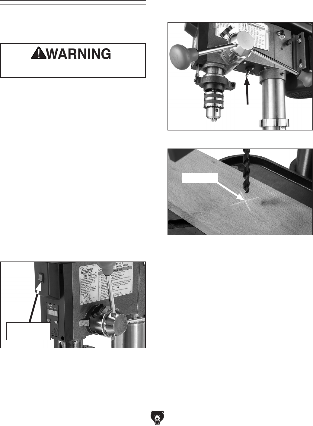
The laser should be checked and adjusted before
starting a new project, and any time you raise or
lower the table, or change workpiece thickness.
Laser Guide 7. Adjust laser (Figure 2), positioning it by hand
so crosshairs align with indentation you made
earlier in surface of workpiece, as shown in
Figure 3.
DO NOT look directly into laser. Severe eye
injury will result.
To adjust laser:
1. DISCONNECT DRILL PRESS FROM
POWER!
2. Install drill bit in chuck (see Installing/
Removing Drill Bits on Page 25 of Model
G7944 manual).
3. Clamp workpiece securely to table.
4. Adjust table so workpiece is within range of
drill bit, then lock table in horizontal position.
5. Lower drill bit so it touches workpiece, mak-
ing a slight indentation in the surface, then
raise bit.
6. Connect drill press to power. Turn laser
ON using switch on front of drill press (see
Figure 1).
Figure 1. Location of laser ON/OFF switch.
Laser ON/
OFF Switch
Figure 2. Location of laser.
Figure 3. Crosshairs aligned with indentation on
workpiece.
Indentation
Model G0794 (Mfd. Since 09/14) -5-
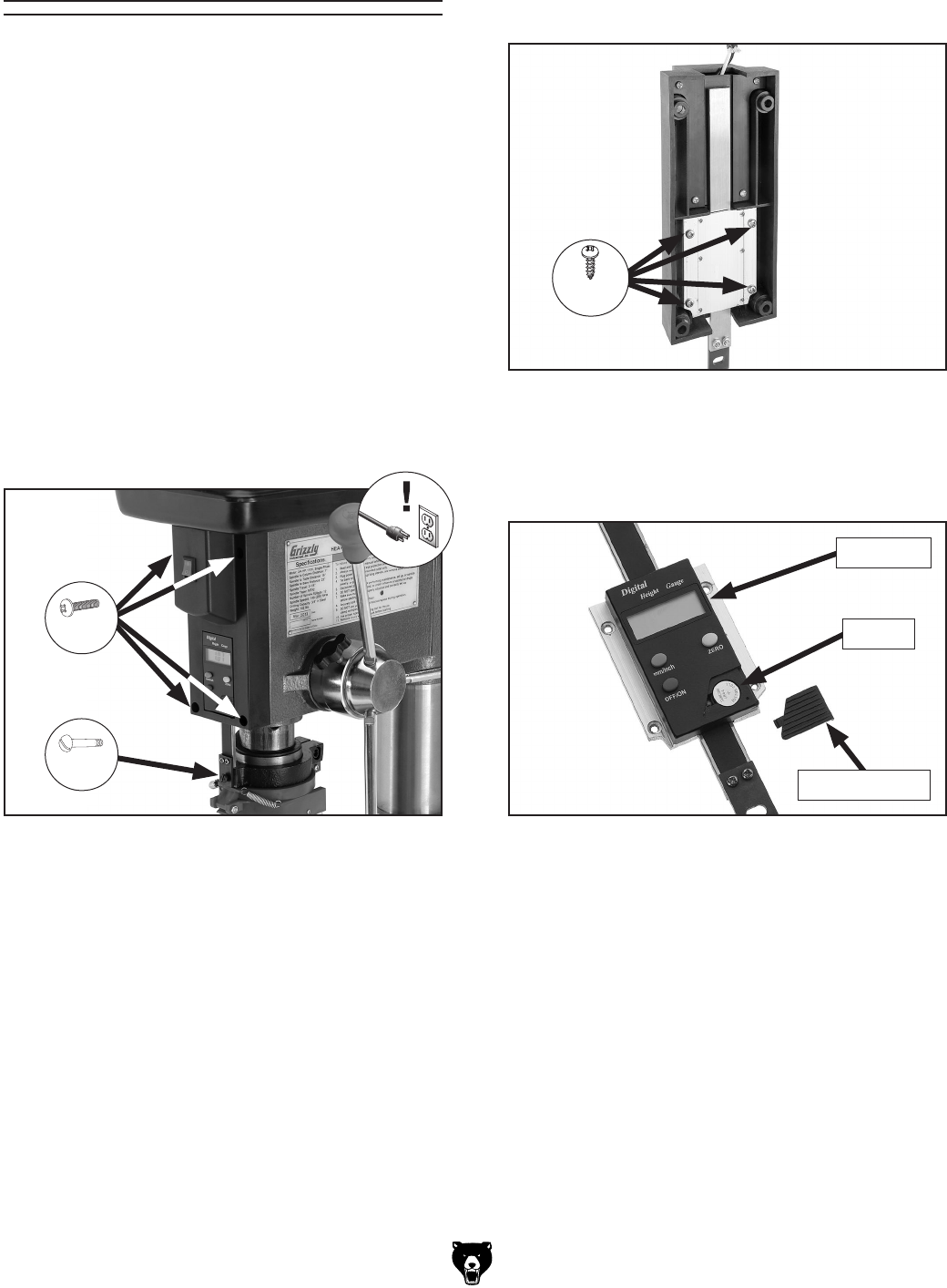
Digital Readout 3. Remove (4) M4 x 12 tap screws shown in
Figure 5, and remove DRO unit from hous-
ing.
Figure 5. DRO housing removed from drill press
head.
x 4
4. Lay DRO unit on a flat surface and remove
battery cover, as shown in Figure 6.
Figure 6. DRO battery cover removed.
DRO Unit
Battery Cover
5. Replace battery with new SR44 button cell
battery and re-install battery cover.
6. Re-install DRO unit and DRO housing, mak-
ing sure to re-install shoulder screw from
Step 2.
The model G0794 is equipped with a digital read-
out (DRO) for precision spindle adjustment. The
DRO is independently powered by a SR44 but-
ton cell battery, which may need to be changed
from time to time. Follow the instructions below to
change the battery.
Tools Needed: Qty
Phillips Head Screwdriver #2 ............................ 1
To change DRO battery:
1. DISCONNECT DRILL PRESS FROM
POWER!
2. Remove (1) shoulder screw, then remove (4)
M5-.8 x 14 Phillips head screws shown in
Figure 4 and remove DRO housing.
Figure 4. Location of DRO mounting screws.
x 4
x 1
Battery

-6- Model G0794 (Mfd. Since 09/14)
WIRING
SHOCK HAZARD. Working on wiring that is con-
nected to a power source is extremely dangerous.
Touching electrified parts will result in personal
injury including but not limited to severe burns,
electrocution, or death. Disconnect the power
from the machine before servicing electrical com-
ponents!
MODIFICATIONS. Modifying the wiring beyond
what is shown in the diagram may lead to unpre-
dictable results, including serious injury or fire.
This includes the installation of unapproved after-
market parts.
WIRE CONNECTIONS. All connections must
be tight to prevent wires from loosening during
machine operation. Double-check all wires dis-
connected or connected during any wiring task to
ensure tight connections.
CIRCUIT REQUIREMENTS. You MUST follow
the requirements at the beginning of this manual
when connecting your machine to a power source.
WIRE/COMPONENT DAMAGE. Damaged wires
or components increase the risk of serious per-
sonal injury, fire, or machine damage. If you notice
that any wires or components are damaged while
performing a wiring task, replace those wires or
components.
MOTOR WIRING. The motor wiring shown in
these diagrams is current at the time of printing
but may not match your machine. If you find this
to be the case, use the wiring diagram inside the
motor junction box.
CAPACITORS/INVERTERS. Some capacitors
and power inverters store an electrical charge for
up to 10 minutes after being disconnected from
the power source. To reduce the risk of being
shocked, wait at least this long before working on
capacitors.
EXPERIENCING DIFFICULTIES. If you are expe-
riencing difficulties understanding the information
included in this section, contact our Technical
Support at (570) 546-9663.
Wiring Safety Instructions
The photos and diagrams
included in this section are
best viewed in color. You
can view these pages in
color at www.grizzly.com.
These pages are current at the time of printing. However, in the spirit of improvement, we may make chang-
es to the electrical systems of future machines. Compare the manufacture date of your machine to the one
stated in this manual, and study this section carefully.
If there are differences between your machine and what is shown in this section, call Technical Support at
(570) 546-9663 for assistance BEFORE making any changes to the wiring on your machine. An updated
wiring diagram may be available. Note: Please gather the serial
number and manufacture date of your
machine before calling. This information can be found on the main machine label.
Model G0794 (Mfd. Since 09/14)
READ ELECTRICAL SAFETY
ON PAGE 6! -7-
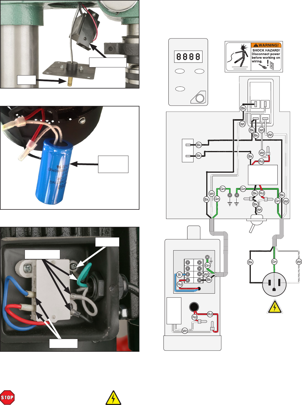
Common
Ground
mm/in zero
off/on
Digital Height Gauge
Laser
Ground
Motor 110V
ON/OFF
Switch
Motor
Junction
Box
+LR44
Battery
Neutral
Hot
Ground
110 VAC
5-15 Plug
L
L
N N
Laser
ON/OFF
Switch
KDC01-101
2/8A 250VDC
1
1A
S. Capacitor
125VAC
200MFD
IN: 120VAC
OUT: 3VDC
TRANSFORMER
GAO YOU
Laser
Start
Capacitor
Figure 7. Start capacitor.
Figure 6. Laser and transformer.
Figure 8. Motor junction box.
From Plug
Ground
G0794 Wiring
To Motor
Transformer
-8- Model G0794 (Mfd. Since 09/14)
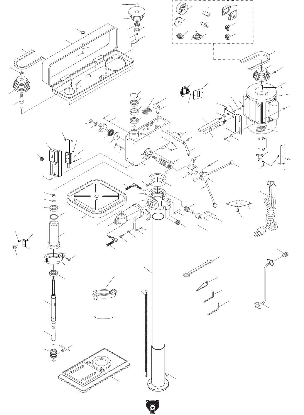
Parts Breakdown
12
3
4
5
6
7
8
9
10
11
12
13
14
15
16
118
17
18
19
20
21 22 23
24
25
26
27
29
30
32
33
34
35 36
37
38 39
40
414243
44
45
46
4849
50
51
52
53
54
55
56
56
28 57 58
58-1 58-2
58-3
58-4 58-6
58-7 58-8
58-9
58-10
59
60
61
62
63
64
65
66
67
68
68
69
70
71
72
73
74
75
76
77
78
79
80
81
82
83
84
85
86
87
88
89
90
91
92
97
98
99
100
104
105
101
119
102
103
110
113
115
116
120
121
122
123
124
125
126
127
128
129
130
131
132
133
134
135
136
136 137
138

Model G0794 (Mfd. Since 09/14) -9-
Parts List
REF PART # DESCRIPTION REF PART # DESCRIPTION
1 P0794001 BASE 55 P0794055 MOTOR MOUNTING PLATE
2 P0794002 HEX BOLT M10-1.5 x 35 56 P0794056 FLAT WASHER 12MM
3 P0794003 LONG RACK 57 P0794057 HEX NUT M12-1.75
4 P0794004 COLUMN W/COLUMN HOLDER 58 P0794058 MOTOR 3/4HP 110V 1-PH
5 P0794005 TABLE BRACKET 58-1 P0794058-1 CAPACITOR COVER
6 P0794006 HANDLE 58-2 P0794058-2 MOTOR JUNCTION BOX
7 P0794007 SET SCREW M6-1 X 10 58-3 P0794058-3 MOTOR FAN COVER
8 P0794008 SHAFT 58-4 P0794058-4 MOTOR FAN
9 P0794009 STUD-SE M6-1 X 12, 17 58-6 P0794058-6 S CAPACITOR 200M 125V 1-3/8 X 2-3/4
10 P0794010 HEX NUT M6-1 58-7 P0794058-7 CENTRIFUGAL SWITCH
11 P0794011 FLAT WASHER 16MM 58-8 P0794058-8 CONTACT PLATE
12 P0794012 HEX BOLT M16-2 X 40 58-9 P0794058-9 BALL BEARING 6203ZZ
13 P0794013 SWIVEL LOCK HANDLE M10-1.5 X 30 58-10 P0794058-10 BALL BEARING 6203ZZ
14 P0794014 TABLE ARM BRACKET 59 P0794059 MOTOR PULLEY
15 P0794015 TABLE 60 P0794060 KEY 5 X 5 X 20
16 P0794016 SWIVEL LOCK HANDLE M12-1.75 X 50 61 P0794061 SET SCREW M6-1 X 10
17 P0794017 GEAR 10T 62 P0794062 V-BELT M24
18 P0794018 WORM GEAR 63 P0794063 CENTER SHAFT
19 P0794019 RACK RING 64 P0794064 BALL BEARING 6202ZZ
20 P0794020 STOP PIN 65 P0794065 BALL BEARING 6202ZZ
21 P0794021 SET SCREW M6-1 X 10 66 P0794066 EXT RETAINING RING 15MM
22 P0794022 FEED SHAFT 67 P0794067 CENTER PULLEY
23 P0794023 DEPTH RING 68 P0794068 FLAT WASHER 6MM
24 P0794024 ROLL PIN 5 X 40 69 P0794069 PHLP HD SCR M6-1 X 10
25 P0794025 DOWNFEED HANDWHEEL HUB 70 P0794070 PHLP HD SCR M5-.8 x 8
26 P0794026 DOWNFEED HANDLE M12-1.75 MALE 71 P0794071 FLAT WASHER 5MM
27 P0794027 DOWNFEED KNOB M12-1.75 FEMALE 72 P0794072 PULLEY COVER KNOB M5-.8
28 P0794028 LOCK WASHER 12MM 73 P0794073 PULLEY COVER
29 P0794029 KNOB BOLT M8-1.25 X 22 74 P0794074 V-BELT M25
30 P0794030 SET SCREW M10-1.5 x 10 75 P0794075 PULLEY NUT
32 P0794032 EXT RETAINING RING 15MM 76 P0794076 SPINDLE PULLEY
33 P0794033 BELT TENSION LEVER 77 P0794077 PULLEY SHAFT
34 P0794034 KNOB BOLT M10-1.5 X 25 78 P0794078 INT RETAINING RING 62MM
35 P0794035 HEX BOLT M8-1.25 X 24 79 P0794079 BALL BEARING 6205ZZ
36 P0794036 FLAT WASHER 8MM 80 P0794080 SPACER
37 P0794037 HEX NUT M8-1.25 81 P0794081 BALL BEARING 6205ZZ
38 P0794038 HEX NUT M10-1.5 82 P0794082 INT RETAINING RING 62MM
39 P0794039 SET SCREW M10-1.5 X 25 PLASTIC 83 P0794083 ROUND NUT M17-1
40 P0794040 HEX NUT M12-1.5 84 P0794084 TAB WASHER
41 P0794041 HEX NUT M12-1.5 85 P0794085 BALL BEARING 6203ZZ
42 P0794042 RETURN SPRING COVER 86 P0794086 RUBBER WASHER 62 X 50 X 2
43 P0794043 COILED RETURN SPRING 87 P0794087 QUILL
44 P0794044 RETURN SPRING PLATE 88 P0794088 BALL BEARING 6205ZZ
45 P0794045 SWITCH/DRO HOUSING 89 P0794089 SPINDLE
46 P0794046 PHLP HD SCR M5-.8 X 14 90 P0794090 DRILL CHUCK ARBOR MT2/JT33
48 P0794048 PHLP HD SCR M5-.8 X 10 91 P0794091 DRILL CHUCK 5/8" X JT33 W/KEY
49 P0794049 CORD CLAMP 92 P0794092 CHUCK KEY 5/16" TH-SE 11T SD-5/8"
50 P0794050 HEADSTOCK CASTING 97 P0794097 LASER SWITCH KCD1-101 2/8A 250VAC
51 P0794051 HEX BOLT M8-1.25 X 16 98 P0794098 GRIZZLY SAFETY PADDLE SWITCH
52 P0794052 SHIFTER 99 P0794099 INT RETAINING RING 38MM
53 P0794053 MOTOR MOUNT SLIDE BAR (SOLID) 100 P0794100 POWER CORD 16G X 3W 73"L 5-15P
54 P0794054 MOTOR MOUNT SLIDE BAR (GROOVED)

-10- Model G0794 (Mfd. Since 09/14)
REF PART # DESCRIPTION REF PART # DESCRIPTION
101 P0794101 HEX WRENCH 5MM 124 P0794124 DRO SLIDE PLATE 16MM X 192MM
102 P0794102 HEX WRENCH 3MM 125 P0794125 TAP SCREW M3 X 8
103 P0794103 DRIFT KEY 126 P0794126 DIGITAL READOUT 40MM X 74MM
104 P0794104 STRAIN RELIEF 1/4"-5/16" ST PLASTIC 127 P0794127 TAP SCREW M4 X 12
105 P0794105 MOTOR CORD 16G 3W 11" 128 P0794128 QUILL CLAMP
110 P0794110 TABLE BOLT WRENCH 129 P0794129 SHOULDER SCREW M4-.7 X 15
113 P0794113 ANGLE SCALE 130 P0794130 CONNECTING PLATE
115 P0794115 CAP SCREW M8-1.25 X 20 131 P0794131 HEX NUT M3-.5
116 P0794116 STRAIN RELIEF 1/4"-5/16" ST PLASTIC 132 P0794132 PHLP HD SCR M3-.5 X 10
118 P0794118 ANGLE INDICATOR 133 P0794133 LASER LIGHT RETAINING PLATE
119 P0794119 MOTOR LABEL 134 P0794134 PHLP HD SCR M5-.8 X 8
120 P0794120 CRANK LEVER 135 P0794135 LASER TRANSFORMER BRACKET
121 P0794121 CHUCK GUARD ASSEMBLY 136 P0794136 PHLP HD SCR M4-.7 X 12
122 P0794122 SWITCH PLATE 137 P0794137 HEX NUT M4-.7
123 P0794123 PHLP HD SCR M4-.7 X 10 138 P0794138 LASER LIGHT ASSEMBLY BY-11-1
Model G0794 (Mfd. Since 09/14) -11-
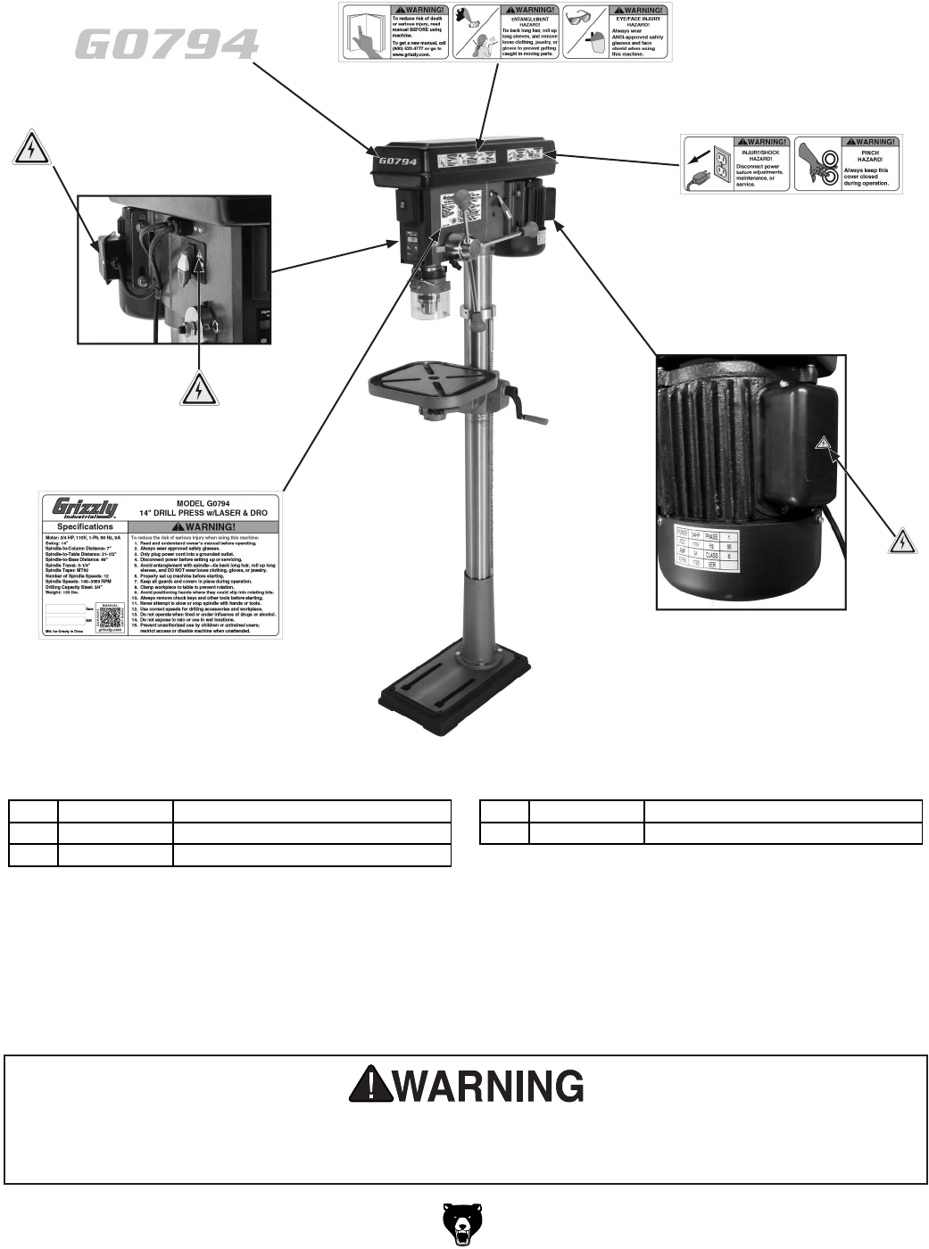
Safety labels help reduce the risk of serious injury caused by machine hazards. If any label comes
off or becomes unreadable, the owner of this machine MUST replace it in the original location
before resuming operations. For replacements, contact (800) 523-4777 or www.grizzly.com.
Labels & Cosmetics
REF PART # DESCRIPTION REF PART # DESCRIPTION
139 P0794139 ELECTRICITY LABEL 142 P0794142 MACHINE ID LABEL
140 P0794140 SAFETY WARNING LABEL A 143 P0794143 MODEL NUMBER LABEL
141 P0794141 SAFETY WARNING LABEL B
139
143
139
140
141
139
142
Place in Center

-12- Model G0794 (Mfd. Since 09/14)
G7943
G7944
MODEL G7943/G7944
12 SPEED HEAVY-DUTY
DRILL PRESS
OWNER'S MANUAL
COPYRIGHT © 1992 BY GRIZZLY INDUSTRIAL, INC. REVISED MAY, 2009 (BL)
WARNING: NO PORTION OF THIS MANUAL MAY BE REPRODUCED IN ANY SHAPE
OR FORM WITHOUT THE WRITTEN APPROVAL OF GRIZZLY INDUSTRIAL, INC.
(FOR MODELS MANUFACTURED SINCE 10/02) #BL3698 PRINTED IN CHINA

This manual provides critical safety instructions on the proper setup,
operation, maintenance, and service of this machine/tool. Save this
document, refer to it often, and use it to instruct other operators.
Failure to read, understand and follow the instructions in this manual
may result in fire or serious personal injury—including amputation,
electrocution, or death.
The owner of this machine/tool is solely responsible for its safe use.
This responsibility includes but is not limited to proper installation in
a safe environment, personnel training and usage authorization,
proper inspection and maintenance, manual availability and compre-
hension, application of safety devices, cutting/sanding/grinding tool
integrity, and the usage of personal protective equipment.
The manufacturer will not be held liable for injury or property damage
from negligence, improper training, machine modifications or misuse.
Some dust created by power sanding, sawing, grinding, drilling, and
other construction activities contains chemicals known to the State
of California to cause cancer, birth defects or other reproductive
harm. Some examples of these chemicals are:
• Lead from lead-based paints.
• Crystalline silica from bricks, cement and other masonry products.
• Arsenic and chromium from chemically-treated lumber.
Your risk from these exposures varies, depending on how often you
do this type of work. To reduce your exposure to these chemicals:
Work in a well ventilated area, and work with approved safety equip-
ment, such as those dust masks that are specially designed to filter
out microscopic particles.
Table of Contents
INTRODUCTION ............................................................................................................................... 3
Foreword .................................................................................................................................... 3
Contact Info ................................................................................................................................ 3
G7943 Machine Data Sheet ....................................................................................................... 4
G7944 Machine Data Sheet ....................................................................................................... 6
Identification ............................................................................................................................... 8
SECTION 1: SAFETY ....................................................................................................................... 9
Safety Instructions for Machinery ............................................................................................... 9
Safety for Drill Presses............................................................................................................. 11
SECTION 2: CIRCUIT REQUIREMENTS ...................................................................................... 12
110V Operation ........................................................................................................................ 12
SECTION 3: SET UP ...................................................................................................................... 13
Set Up Safety ........................................................................................................................... 13
Items Needed for Set Up ......................................................................................................... 13
Unpacking ................................................................................................................................ 13
Inventory ................................................................................................................................... 14
Hardware Recognition Chart .................................................................................................... 15
Clean Up .................................................................................................................................. 16
Site Considerations .................................................................................................................. 16
Column and Base ..................................................................................................................... 17
Table Support ........................................................................................................................... 17
Headstock ................................................................................................................................ 19
Drill Chuck & Arbor................................................................................................................... 20
Downfeed Handles & Belt Cover Knob .................................................................................... 21
Table ........................................................................................................................................ 21
Light .......................................................................................................................................... 22
Test Run ................................................................................................................................... 22
Mounting ................................................................................................................................... 23
Recommended Adjustments .................................................................................................... 24
SECTION 4: OPERATIONS ........................................................................................................... 25
Operation Safety ...................................................................................................................... 25
Switch/Lockout ......................................................................................................................... 25
Installing/Removing Drill Bits .................................................................................................... 25
Choosing Speeds ..................................................................................................................... 26
Changing Speeds ..................................................................................................................... 27
Drilling ...................................................................................................................................... 28
Depth Stop ............................................................................................................................... 29
Adjusting Table......................................................................................................................... 29
Arbor Removal ......................................................................................................................... 30
SECTION 5: ACCESSORIES ......................................................................................................... 31
SECTION 6: MAINTENANCE......................................................................................................... 34
General ..................................................................................................................................... 34
Cleaning ................................................................................................................................... 34
Unpainted Cast Iron ................................................................................................................. 34
Lubrication ................................................................................................................................ 34
V-Belts ...................................................................................................................................... 34
SECTION 7: SERVICE ................................................................................................................... 35
About Service ........................................................................................................................... 35
Troubleshooting ........................................................................................................................ 35
Depth Stop Calibration ............................................................................................................. 38
Feed Shaft Spring Tension ...................................................................................................... 38
SECTION 8: WIRING ...................................................................................................................... 40
Wiring Safety Instructions ........................................................................................................ 40
Electrical Components ............................................................................................................. 41
G7943/G7944 Wiring Diagram ................................................................................................. 42
G7943/G7944 Breakdown ........................................................................................................ 43
G7943/G7944 Parts List ........................................................................................................... 44
Label Placement and Parts List ............................................................................................... 46
WARRANTY AND RETURNS ........................................................................................................ 49

Model G7943/G7944 (Mfg. 10/02+) -3-
If you have any comments regarding this manual,
please write to us at the address below:
Grizzly Industrial, Inc.
C/O Technical Documentation Manager
P.O. Box 2069
Bellingham, WA 98227-2069
We stand behind our machines. If you have any
service questions or parts requests, please call or
write us at the location listed below.
Grizzly Industrial, Inc.
1203 Lycoming Mall Circle
Muncy, PA 17756
Phone: (570) 546-9663
Fax: (800) 438-5901
E-Mail: techsupport@grizzly.com
Web Site: http://www.grizzly.com
Foreword
INTRODUCTION
Contact Info
We are proud to offer the Model G7943/G7944
12 Speed Heavy Duty Drill Press. This machine
is part of a growing Grizzly family of fine wood-
working and metalworking machinery. When used
according to the guidelines set forth in this manu-
al, you can expect years of trouble-free, enjoyable
operation and proof of Grizzly’s commitment to
customer satisfaction.
We are pleased to provide this manual with the
Model G7943/G7944. It was written to guide you
through assembly, review safety considerations,
and cover general operating procedures. It repre-
sents our effort to produce the best documenta-
tion possible.
The specifications, drawings, and photographs
illustrated in this manual represent the Model
G7943/G7944 as supplied when the manual was
prepared. However, owing to Grizzly’s policy of
continuous improvement, changes may be made
at any time with no obligation on the part of Grizzly.
For your convenience, we always keep current
Grizzly manuals available on our website at www.
grizzly.com. Any updates to your machine will be
reflected in these manuals as soon as they are
complete. Visit our site often to check for the lat-
est updates to this manual!

-4- Model G7943/G7944 (Mfg. 10/02+)
The information contained herein is deemed accurate as of 12/8/2014 and represents our most recent product specifications.
Due to our ongoing improvement efforts, this information may not accurately describe items previously purchased. PAGE 1 OF 3Model G7943
MACHINE DATA
SHEET
Customer Service #: (570) 546-9663 · To Order Call: (800) 523-4777 · Fax #: (800) 438-5901
MODEL G7943 12 SPEED HEAVY-DUTY BENCH-TOP DRILL
PRESS
Product Dimensions:
Weight.............................................................................................................................................................. 142 lbs.
Width (side-to-side) x Depth (front-to-back) x Height........................................................................... 14 x 24 x 38 in.
Footprint (Length x Width)............................................................................................................................ 18 x 11 in.
Shipping Dimensions:
Type..................................................................................................................................................... Cardboard Box
Content........................................................................................................................................................... Machine
Weight.............................................................................................................................................................. 154 lbs.
Length x Width x Height....................................................................................................................... 33 x 20 x 12 in.
Must Ship Upright.................................................................................................................................................... No
Electrical:
Power Requirement........................................................................................................... 110V, Single-Phase, 60 Hz
Prewired Voltage.................................................................................................................................................. 110V
Full-Load Current Rating.......................................................................................................................................... 9A
Minimum Circuit Size.............................................................................................................................................. 15A
Connection Type....................................................................................................................................... Cord & Plug
Power Cord Included.............................................................................................................................................. Yes
Power Cord Length.......................................................................................................................................... 8-1/2 ft.
Power Cord Gauge......................................................................................................................................... 16 AWG
Plug Included.......................................................................................................................................................... Yes
Included Plug Type................................................................................................................................................ 5-15
Switch Type.................................................................................................. Paddle Safety Switch w/Removable Key
Motors:
Main
Type................................................................................................................. TEFC Capacitor-Start Induction
Horsepower............................................................................................................................................. 3/4 HP
Phase............................................................................................................................................ Single-Phase
Amps.............................................................................................................................................................. 9A
Speed................................................................................................................................................ 1720 RPM
Power Transfer ............................................................................................................................... V-Belt Drive
Bearings..................................................................................................... Shielded & Permanently Lubricated
Main Specifications:
Construction
Table....................................................................................................................... Precision-Ground Cast Iron
Spindle Housing................................................................................................................................... Cast Iron
Column....................................................................................................................................................... Steel
Head.................................................................................................................................................... Cast Iron
Base..................................................................................................................................................... Cast Iron
Paint Type/Finish.................................................................................................................................... Enamel
Head Information
Head Swivel.......................................................................................................................................... 360 deg.
G7943 Machine Data Sheet

Model G7943/G7944 (Mfg. 10/02+) -5-
The information contained herein is deemed accurate as of 12/8/2014 and represents our most recent product specifications.
Due to our ongoing improvement efforts, this information may not accurately describe items previously purchased. PAGE 2 OF 3Model G7943
Other Related Information
Base Length............................................................................................................................................... 18 in.
Base Width................................................................................................................................................ 11 in.
Quill Diameter....................................................................................................................................... 2.040 in.
Depth Stop Type............................................................................................ Threaded Rod with Positive Stop
Column Diameter.................................................................................................................................. 3.150 in.
Has Work Light............................................................................................................................................. Yes
Light Socket Type....................................................................................................................... 110V, Std Bulb
Maximum Bulb Wattage............................................................................................................................. 60 W
Spindle Information
Spindle Taper............................................................................................................................................ MT#2
Spindle Travel........................................................................................................................................ 3-1/4 in.
Distance From Spindle To Column.............................................................................................................. 7 in.
Distance From Spindle To Table............................................................................................................... 16 in.
Distance From Spindle To Base................................................................................................................ 23 in.
Table Information
Table Length........................................................................................................................................ 11-3/8 in.
Table Width......................................................................................................................................... 11-3/8 in.
Table Thickness.................................................................................................................................... 1-1/4 in.
Floor To Table Height.............................................................................................................. 9-1/2 – 23-1/2 in.
Vertical Table Movement............................................................................................. Crank Handle Operation
Table Swing.......................................................................................................................................... 360 deg.
Max Table Tilt (Left/Right)...................................................................................................................... 90 deg.
Table Swivel Around Center................................................................................................................. 360 deg.
Table Swivel Around Column............................................................................................................... 360 deg.
Maximum Movement Of Work Table................................................................................................... 25-3/4 in.
Number of T Slots............................................................................................................................................. 4
T Slot Width.............................................................................................................................................. 5/8 in.
T Slot Length......................................................................................................................................... 3-7/8 in.
Operation Information
Type......................................................................................................................................................... Bench
Swing......................................................................................................................................................... 14 in.
Drilling Capacity (Mild Steel)........................................................................................................ 3/4 in. in Steel
Number of Spindle Speeds............................................................................................................................. 12
Range of Spindle Speeds........................................................................................................ 140 – 3050 RPM
Drill Chuck Type....................................................................................................................... JT33 Key Chuck
Drill Chuck Size............................................................................................................................. 1/64 – 5/8 in.
Other Specifications:
Country of Origin ................................................................................................................................................ China
Warranty ........................................................................................................................................................... 1 Year
Approximate Assembly & Setup Time ........................................................................................................ 45 Minutes
Serial Number Location ................................................................................................................... ID Label on Head
ISO 9001 Factory .................................................................................................................................................. Yes
CSA, ETL, or UL Certified/Listed ............................................................................................................................ No
Awards .............................................................................. Popular Woodworking Editor's Choice Tool Buying Guide

-6- Model G7943/G7944 (Mfg. 10/02+)
The information contained herein is deemed accurate as of 12/8/2014 and represents our most recent product specifications.
Due to our ongoing improvement efforts, this information may not accurately describe items previously purchased. PAGE 1 OF 3Model G7944
MACHINE DATA
SHEET
Customer Service #: (570) 546-9663 · To Order Call: (800) 523-4777 · Fax #: (800) 438-5901
MODEL G7944 12 SPEED HEAVY-DUTY 14" FLOOR DRILL
PRESS
Product Dimensions:
Weight.............................................................................................................................................................. 155 lbs.
Width (side-to-side) x Depth (front-to-back) x Height........................................................................... 14 x 24 x 64 in.
Footprint (Length x Width)............................................................................................................................ 18 x 11 in.
Shipping Dimensions:
Type..................................................................................................................................................... Cardboard Box
Content........................................................................................................................................................... Machine
Weight.............................................................................................................................................................. 171 lbs.
Length x Width x Height....................................................................................................................... 56 x 20 x 10 in.
Must Ship Upright.................................................................................................................................................... No
Electrical:
Power Requirement........................................................................................................... 110V, Single-Phase, 60 Hz
Prewired Voltage.................................................................................................................................................. 110V
Full-Load Current Rating.......................................................................................................................................... 9A
Minimum Circuit Size.............................................................................................................................................. 15A
Connection Type....................................................................................................................................... Cord & Plug
Power Cord Included.............................................................................................................................................. Yes
Power Cord Length.......................................................................................................................................... 8-1/2 ft.
Power Cord Gauge......................................................................................................................................... 16 AWG
Plug Included.......................................................................................................................................................... Yes
Included Plug Type................................................................................................................................................ 5-15
Switch Type.................................................................................................. Paddle Safety Switch w/Removable Key
Motors:
Main
Type................................................................................................................. TEFC Capacitor-Start Induction
Horsepower............................................................................................................................................. 3/4 HP
Phase............................................................................................................................................ Single-Phase
Amps.............................................................................................................................................................. 9A
Speed................................................................................................................................................ 1720 RPM
Power Transfer ............................................................................................................................... V-Belt Drive
Bearings..................................................................................................... Shielded & Permanently Lubricated
Main Specifications:
Construction
Table....................................................................................................................... Precision-Ground Cast Iron
Spindle Housing................................................................................................................................... Cast Iron
Column....................................................................................................................................................... Steel
Head.................................................................................................................................................... Cast Iron
Base..................................................................................................................................................... Cast Iron
Paint Type/Finish.................................................................................................................................... Enamel
Head Information
Head Swivel.......................................................................................................................................... 360 deg.
G7944 Machine Data Sheet

Model G7943/G7944 (Mfg. 10/02+) -7-
The information contained herein is deemed accurate as of 12/8/2014 and represents our most recent product specifications.
Due to our ongoing improvement efforts, this information may not accurately describe items previously purchased. PAGE 2 OF 3Model G7944
Other Related Information
Base Length............................................................................................................................................... 18 in.
Base Width................................................................................................................................................ 11 in.
Quill Diameter....................................................................................................................................... 2.040 in.
Depth Stop Type.......................................................................................................................................... Hub
Column Diameter.................................................................................................................................. 3.150 in.
Mobile Base........................................................................................................................................... D2260A
Has Work Light............................................................................................................................................. Yes
Light Socket Type....................................................................................................................... 110V, Std Bulb
Maximum Bulb Wattage............................................................................................................................. 60 W
Spindle Information
Spindle Taper............................................................................................................................................ MT#2
Spindle Travel........................................................................................................................................ 3-1/4 in.
Distance From Spindle To Column.............................................................................................................. 7 in.
Distance From Spindle To Table......................................................................................................... 31-1/2 in.
Distance From Spindle To Base................................................................................................................ 49 in.
Table Information
Table Length........................................................................................................................................ 11-3/8 in.
Table Width......................................................................................................................................... 11-3/8 in.
Table Thickness.................................................................................................................................... 1-1/4 in.
Floor To Table Height........................................................................................................................ 20 – 46 in.
Vertical Table Movement............................................................................................. Crank Handle Operation
Table Swing.......................................................................................................................................... 360 deg.
Max Table Tilt (Left/Right)...................................................................................................................... 90 deg.
Table Swivel Around Center................................................................................................................. 360 deg.
Table Swivel Around Column............................................................................................................... 360 deg.
Maximum Movement Of Work Table......................................................................................................... 14 in.
Number of T Slots............................................................................................................................................. 4
T Slot Width.............................................................................................................................................. 5/8 in.
T Slot Length......................................................................................................................................... 3-7/8 in.
Operation Information
Type........................................................................................................................................................... Floor
Swing......................................................................................................................................................... 14 in.
Drilling Capacity (Mild Steel)........................................................................................................ 3/4 in. in Steel
Number of Spindle Speeds............................................................................................................................. 12
Range of Spindle Speeds........................................................................................................ 140 – 3050 RPM
Drill Chuck Type....................................................................................................................... JT33 Key Chuck
Drill Chuck Size............................................................................................................................. 1/64 – 5/8 in.
Other Specifications:
Country of Origin ................................................................................................................................................ China
Warranty ........................................................................................................................................................... 1 Year
Approximate Assembly & Setup Time ........................................................................................................ 45 Minutes
Serial Number Location ................................................................................................................... ID Label on Head
ISO 9001 Factory .................................................................................................................................................. Yes
CSA, ETL, or UL Certified/Listed ............................................................................................................................ No
Awards .............. Popular Woodworking Editor's Choice Tool Buying Guide, American Woodworker Best Buy 2001,
Woodworker's Journal Tools That Endure
-8- Model G7943/G7944 (Mfg. 10/02+)
4
89
7
11
5
4
3
2
6
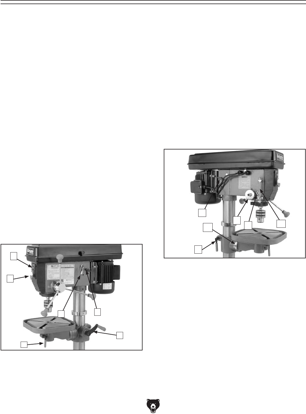
Identification
Figure 1. Right-side controls.
Figure 2. Left-side controls.
Refer to the list below and see Figures 1 & 2 to
become familiar with the drill press controls.
1. Light Switch: Turns light ON/OFF.
2. Power Switch: Turns motor ON/OFF.
3. Belt Tension Lever: Adjusts motor location
to increase/decrease belt tension.
4. Belt Tension Lock: Locks motor in place to
maintain belt tension.
5. Crank Lever: Raises/lowers table.
6. Small Lock Lever: Locks table rotation.
7. Large Lock Lever: Locks table height.
8. Torsion Spring: Returns quill into head-
stock.
9. Lash Screw: Removes quill lash.
10. Depth Stop: Limits quill travel to a pre-set
drilling depth.
11. Table Tilt Scale: Displays current table-tilt
angle.
Refer to the list below to become familiar with
the drill press terms and definitions.
Headstock: The cast iron upper portion of the drill
press, which houses the quill and work light, and
supports the motor and belt housing.
Drift Key: A wedge-shaped tool used to separate
tapers.
T-Slot: A slot in a table used to trap a hex nut or
hex bolt to clamp down a workpiece or a vise.
Arbor: A tapered shaft that connects the chuck to
the spindle.
Quill: Houses the spindle and bearings.
Spindle: The hollow shaft that accepts the arbor.
1
10

Model G7943/G7944 (Mfg. 10/02+) -9-
4. ALWAYS USE HEARING PROTECTION
WHEN OPERATING MACHINERY.
Machinery noise can cause permanent
hearing damage.
5. WEAR PROPER APPAREL. DO NOT
wear loose clothing, gloves, neckties, rings,
or jewelry which may get caught in moving
parts. Wear protective hair covering to con-
tain long hair and wear non-slip footwear.
6. NEVER OPERATE MACHINERY WHEN
TIRED, OR UNDER THE INFLUENCE OF
DRUGS OR ALCOHOL. Be mentally alert
at all times when running machinery.
1. READ THROUGH THE ENTIRE MANUAL
BEFORE STARTING MACHINERY.
Machinery presents serious injury hazards
to untrained users.
2. ALWAYS USE ANSI APPROVED
SAFETY GLASSES WHEN OPERATING
MACHINERY. Everyday eyeglasses only
have impact resistant lenses, they are
NOT safety glasses.
3. ALWAYS WEAR AN ANSI APPROVED
RESPIRATOR WHEN OPERATING
MACHINERY THAT PRODUCES DUST.
Wood dust is a carcinogen and can cause
cancer and severe respiratory illnesses.
For Your Own Safety, Read Instruction
Manual Before Operating this Machine
The purpose of safety symbols is to attract your attention to possible hazardous conditions. This
manual uses a series of symbols and signal words which are intended to convey the level of
importance of the safety messages. The progression of symbols is described below. Remember
that safety messages by themselves do not eliminate danger and are not a substitute for proper
accident prevention measures.
Indicates a potentially hazardous situation which, if not avoided,
MAY result in minor or moderate injury. It may also be used to alert
against unsafe practices.
Indicates a potentially hazardous situation which, if not avoided,
COULD result in death or serious injury.
Indicates an imminently hazardous situation which, if not avoided,
WILL result in death or serious injury.
This symbol is used to alert the user to useful information about
proper operation of the machine.
NOTICE
Safety Instructions for Machinery
SECTION 1: SAFETY

-10- Model G7943/G7944 (Mfg. 10/02+)
7. ONLY ALLOW TRAINED AND PROP-
ERLY SUPERVISED PERSONNEL TO
OPERATE MACHINERY. Make sure oper-
ation instructions are safe and clearly
understood.
8. KEEP CHILDREN AND VISITORS AWAY.
Keep all children and visitors a safe dis-
tance from the work area.
9. MAKE WORKSHOP CHILD PROOF. Use
padlocks, master switches, and remove
start switch keys.
10. NEVER LEAVE WHEN MACHINE IS
RUNNING. Turn power OFF and allow all
moving parts to come to a complete stop
before leaving machine unattended.
11. DO NOT USE IN DANGEROUS
ENVIRONMENTS. DO NOT use machin-
ery in damp, wet locations, or where any
flammable or noxious fumes may exist.
12. KEEP WORK AREA CLEAN AND WELL
LIT. Clutter and dark shadows may cause
accidents.
13. USE A GROUNDED EXTENSION CORD
RATED FOR THE MACHINE AMPERAGE.
Undersized cords overheat and lose power.
Replace extension cords if they become
damaged. DO NOT use extension cords
for 220V machinery.
14.
ALWAYS DISCONNECT FROM POWER
SOURCE BEFORE SERVICING
MACHINERY. Make sure switch is in
OFF
position before reconnecting.
15. MAINTAIN MACHINERY WITH CARE.
Keep blades sharp and clean for best and
safest performance. Follow instructions for
lubricating and changing accessories.
16. MAKE SURE GUARDS ARE IN PLACE
AND WORK CORRECTLY BEFORE
USING MACHINERY.
Safety Instructions for Machinery
17. REMOVE ADJUSTING KEYS AND
WRENCHES. Make a habit of checking for
keys and adjusting wrenches before turn-
ing machinery ON.
18. CHECK FOR DAMAGED PARTS
BEFORE USING MACHINERY. Check
for binding and alignment of parts, broken
parts, part mounting, loose bolts, and any
other conditions that may affect machine
operation. Repair or replace damaged
parts.
19. USE RECOMMENDED ACCESSORIES.
Refer to the instruction manual for recom-
mended accessories. The use of improper
accessories may cause risk of injury.
20. DO NOT FORCE MACHINERY. Work at
the speed for which the machine or acces-
sory was designed.
21. SECURE WORKPIECE. Use clamps or
a vise to hold the workpiece when practi-
cal. A secured workpiece protects your
hands and frees both hands to operate the
machine.
22. DO NOT OVERREACH. Keep proper foot-
ing and balance at all times.
23. MANY MACHINES WILL EJECT
WORKPIECE TOWARD OPERATOR.
Know and avoid conditions that cause the
workpiece to "kickback."
24. ALWAYS LOCK MOBILE BASES
(IF USED) BEFORE OPERATING
MACHINERY.
25. BE AWARE THAT CERTAIN WOODS
MAY CAUSE AN ALLERGIC REACTION
in people and animals, especially when
exposed to fine dust. Make sure you
know what type of wood dust you will be
exposed to and always wear an approved
respirator.

Model G7943/G7944 (Mfg. 10/02+) -11-
1. EYE/FACE/HAND PROTECTION. A face
shield used with safety glasses is rec-
ommended. Always keep hands and fin-
gers away from the drill bit. Never hold a
workpiece by hand while drilling! DO NOT
wear gloves when operating the drill.
2. SECURING BIT. Properly tighten and
securely lock the drill bit in the chuck.
3. CORRECT BIT. Use only round, hex, or
triangular shank drill bits.
4. ADJUSTING KEYS AND WRENCHES.
Remove all adjusting keys and wrenches
before turning the machine ON.
5. DRILLING SHEET METAL. Never drill
sheet metal unless it is securely clamped to
the table.
6. SURFACE /WORKPIECE PREPARATION.
Never turn the drill press ON before clearing
the table of all objects (tools, scrap wood,
etc.) DO NOT drill material that does not
have a flat surface, unless a suitable sup-
port is used.
7. DAMAGED TOOLS. Never use tools in poor
condition. Dull or damaged cutting tools
are hard to control and may cause serious
injury.
Safety for Drill Presses
8. DRILL OPERATION. Never start the drill
press with the drill bit pressed against the
workpiece. Feed the drill bit evenly into the
workpiece. Back the bit out of deep holes.
Turn the machine OFF and clear chips and
scrap pieces with a brush. Shut power OFF,
remove drill bit, and clean table before leav-
ing the machine.
9. OPERATING SPEED. Always operate your
drill press at speeds that are appropriate
for the drill bit size and the material that you
are drilling.
10. MAINTENANCE/SPEED CHANGES.
Never do maintenance or change speeds
with the machine plugged in.
11. MOUNTING WORKPIECES. Use clamps
or vises to secure workpiece before drill-
ing. Position work so you avoid drilling into
the table.
12. TABLE LOCK. Make sure the table lock is
tightened before starting the drill press.
13. EXPERIENCING DIFFICULTIES. If at
any time you are experiencing difficulties
performing the intended operation, stop
using the machine! Contact our Service
Department at (570) 546-9663.
No list of safety guidelines can be complete.
Every shop environment is different. Always
consider safety first, as it applies to your
individual working conditions. Use this and
other machinery with caution and respect.
Failure to do so could result in serious per-
sonal injury, damage to equipment, or poor
work results.
Like all machines there is danger associated
with this machine. Accidents are frequently
caused by lack of familiarity or failure to pay
attention. Use this machine with respect
and caution to lessen the possibility of
operator injury. If normal safety precautions
are overlooked or ignored, serious personal
injury may occur.
-12- Model G7943/G7944 (Mfg. 10/02+)
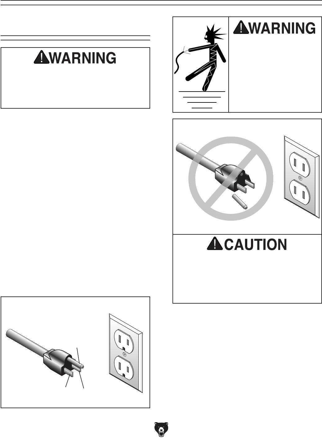
Figure 3. Typical type 5-15 plug and receptacle.
Grounding Prong
Neutral Hot
5-15 PLUG
GROUNDED
5-15 RECEPTACLE
Serious personal injury could occur if you
connect the machine to the power source
before you have completed the set up pro-
cess. DO NOT connect the machine to the
power source until instructed to do so.
110V Operation
Amperage Draw
The 3⁄4 HP motor on the Model G7943/G7944 will
draw the following amps:
Motor Draw ..............................................9 Amps
Circuit Requirements
Whether you have a dedicated or shared circuit,
ONLY connect your machine to a circuit with
a verified ground, correctly sized wiring, and a
properly rated circuit breaker. Obey all applicable
safety and electrical codes, including the National
Electric Code (NEC). If you are unsure about
any wiring practices, consult a qualified elec-
trician.
Minimum Circuit Requirement ................. 15 Amp
Plug/Receptacle Type
Included Plug Type ........................... NEMA 5-15
This machine must have a ground prong in
the plug to help ensure that it is grounded.
DO NOT remove ground prong from plug
to fit into a two-pronged outlet! If the plug
will not fit the outlet, have the proper outlet
installed by a qualified electrician.
Extension Cords
We do not recommend the use of extension
cords. If you find it absolutely necessary to use
an extension cord with your machine:
• Use at least a 10 gauge cord that does not
exceed 50 feet in length!
• The extension cord must also contain a
ground wire and plug pin.
• A qualified electrician MUST size cords over
50 feet long to prevent motor damage.
SECTION 2: CIRCUIT REQUIREMENTS
Electrocution or fire could
result if this machine is
not grounded correctly or
if your electrical configu-
ration does not comply
with local and state codes.
Ensure compliance by
checking with a qualified
electrician!
Model G7943/G7944 (Mfg. 10/02+) -13-
The Model G7943/G7944 was carefully packed
when it left our warehouse. If you discover the
machine is damaged after you have signed
for delivery, please immediately call Customer
Service at (570) 546-9663 for advice.
Save the containers and all packing materials for
possible inspection by the carrier or its agent.
Otherwise, filing a freight claim can be difficult.
When you are completely satisfied with the con-
dition of your shipment, you should inventory the
contents.
Wear safety glasses dur-
ing the entire set up pro-
cess!
This machine presents
serious injury hazards
to untrained users. Read
through this entire manu-
al to become familiar with
the controls and opera-
tions before starting the
machine!
Unpacking
Set Up Safety
SECTION 3: SET UP
The Model G7943/G7944
is a heavy machine. DO
NOT over-exert yourself
while unpacking or mov-
ing your machine—get
assistance.
The following items are needed to complete the
set up process, but are not included with your
machine:
Description Qty
• Wrench 16mm ............................................ 1
• Wrench 9⁄16 .................................................. 1
• Plumb Bob .................................................. 1
• People for Lifting Help ................................ 1
• Rubber Mallet ............................................. 1
• 60W Light Bulb ........................................... 1
• Permanent Marker ...................................... 1
• Lag Bolts 3⁄8-16 x 3 (or length as needed) . . 4
• Carriage Bolts M10-1.5 x 95 ....................... 4
• Flat Washers 10mm ................................... 4
• Hex Nuts M10-1.5 ...................................... 4
• Ruler ........................................................... 1
• Drill ............................................................. 1
• Drill Bit 11⁄32" ................................................ 1
• Plywood 3⁄4" x 23
3⁄4" x 233⁄4" ........................ 2
• Wood Glue ................................. As Needed
• Wood Screws #6 x 11⁄4" ............................ 24
Items Needed for
Set Up
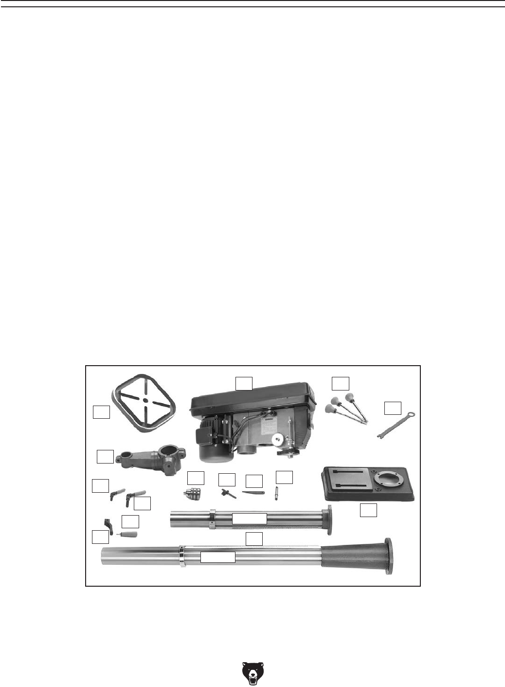
-14- Model G7943/G7944 (Mfg. 10/02+)
Inventory
Figure 4. G7943/G7943 box inventory.
G7944
G7943
1
If any nonproprietary parts are missing (e.g. a nut or a washer), we would be glad to replace them, but for
the sake of expediency, you can get replacements at a hardware store.
Use Figure 4 and the inventory list below to inventory your drill press parts:
Description Qty
1. Table .......................................................... 1
2. Table Support Assembly ............................ 1
3. Small Lock Lever ........................................ 1
4. Large Lock Lever ....................................... 1
5. Crank Lever ................................................ 1
6. Handle ........................................................ 1
7. Column ....................................................... 1
8. Base ........................................................... 1
9. Lock Wrench .............................................. 1
10. Downfeed Handles ..................................... 3
11. Arbor ........................................................... 1
12. Drift Key ...................................................... 1
13. Chuck Key .................................................. 1
14. Chuck ......................................................... 1
15. Headstock Assembly .................................. 1
16. Hardware Bag (Not Shown) ....................... 1
—Belt Cover Knob ..................................... 1
—Hex Wrench 3mm ................................... 1
—Hex Wrench 5mm ................................... 1
—Hex Bolt M10-1.5 x 25mm ...................... 4
11
10
13 12
15
14
5
4
3
9
8
7
6
2
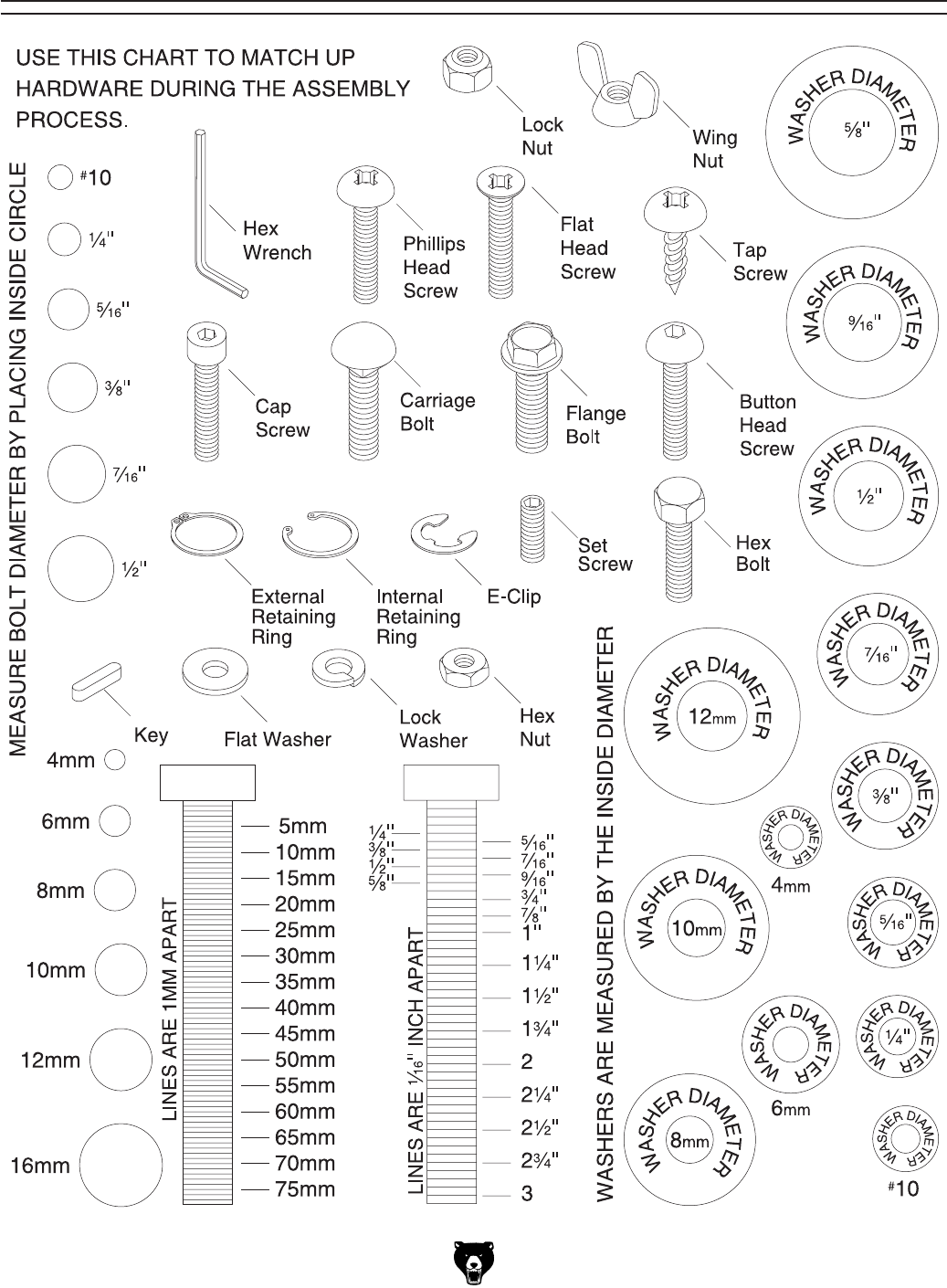
Model G7943/G7944 (Mfg. 10/02+) -15-
Hardware Recognition Chart
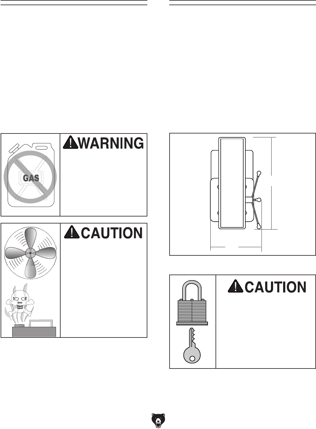
-16- Model G7943/G7944 (Mfg. 10/02+)
Figure 5. Working clearances.
Floor Load
Refer to the Machine Data Sheet for weight and
footprint specifications for your machine. Some
residential floors may require additional reinforce-
ment to support both the machine and operator.
Working Clearances
Consider existing and anticipated needs, size of
material to be processed through each machine,
and space for auxiliary stands, work tables or
other machinery when establishing a location
for your machine. See Figure 5 for the minimum
working clearances of the Model G7943/G7944.
Unsupervised children and
visitors inside your shop
could cause serious per-
sonal injury to themselves.
Lock all entrances to the
shop when you are away and
DO NOT allow unsupervised
children or visitors in your
shop at any time!
The unpainted surfaces are coated with a waxy
oil to protect them from corrosion during ship-
ment. Remove this protective coating with a sol-
vent cleaner or citrus-based degreaser such as
Grizzly’s G7895 Degreaser. To clean thoroughly,
some parts may need to be removed. For opti-
mum performance from your machine, make
sure you clean all moving parts or sliding
contact surfaces that are coated. Avoid chlo-
rine-based solvents, such as acetone or brake
parts cleaner, as they may damage painted sur-
faces should they come in contact. Always follow
the manufacturer’s instructions when using any
type of cleaning product.
Site ConsiderationsClean Up
Gasoline and petroleum
products have low flash
points and could cause
an explosion or fire if
used to clean machinery.
DO NOT use gasoline or
petroleum products to
clean the machinery.
Many of the solvents
commonly used to clean
machinery can be toxic
when inhaled or ingest-
ed. Lack of ventilation
while using these sol-
vents could cause seri-
ous personal health risks
or fire. Take precautions
from this hazard by only
using cleaning solvents
in a well ventilated area.
24"
14"
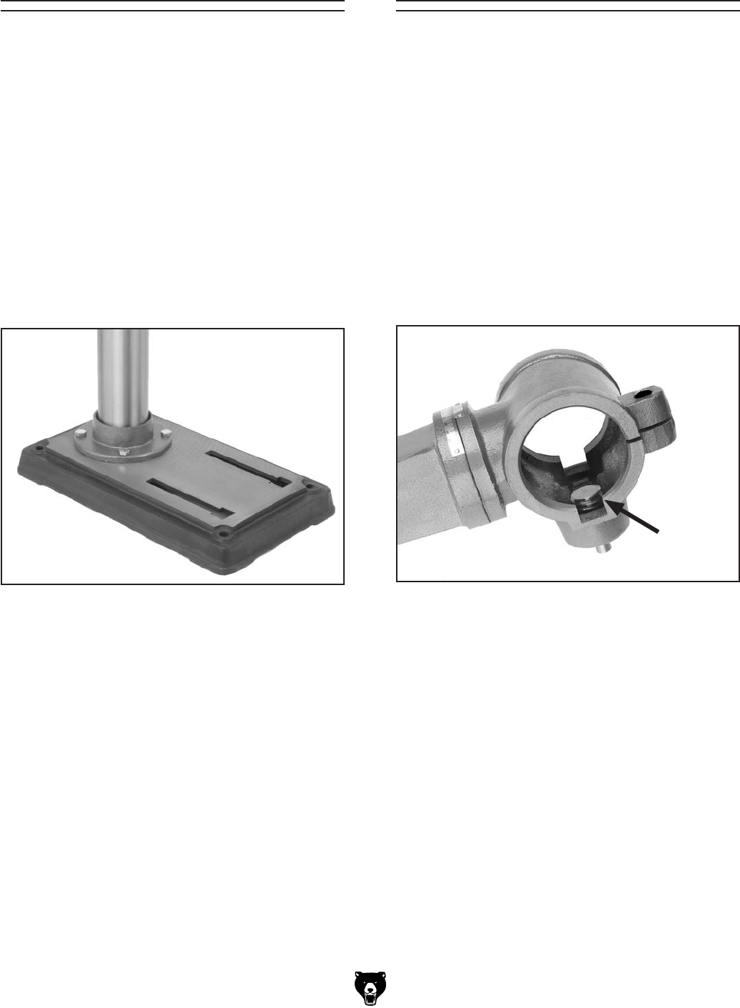
Model G7943/G7944 (Mfg. 10/02+) -17-
Table Support
Components and Hardware Needed: Qty
Table Support Assembly ................................... 1
Crank Handle .................................................... 1
Handle ............................................................... 1
Large Lock Lever ............................................... 1
Small Lock Lever ............................................... 1
The table support must be installed as described
to properly assemble your drill press.
To install the table support:
1. Check to make sure the pinion is inserted
into the table support, as shown in Figure 7,
so the pinion and gear teeth mesh together.
Figure 7. Pinion correctly installed in table
support.
Figure 6. Column secured to base.
Components and Hardware Needed: Qty
Base ...................................................................1
Column ...............................................................1
Hex Bolts M10-1.5 x 25 ......................................4
The column must be secured on the base to
properly assemble your drill press.
To secure the column to the base:
1. Place the column on the base and align the
mounting holes.
2. Secure the column to the base with the four
hex bolts, as shown in Figure 6.
Column and Base
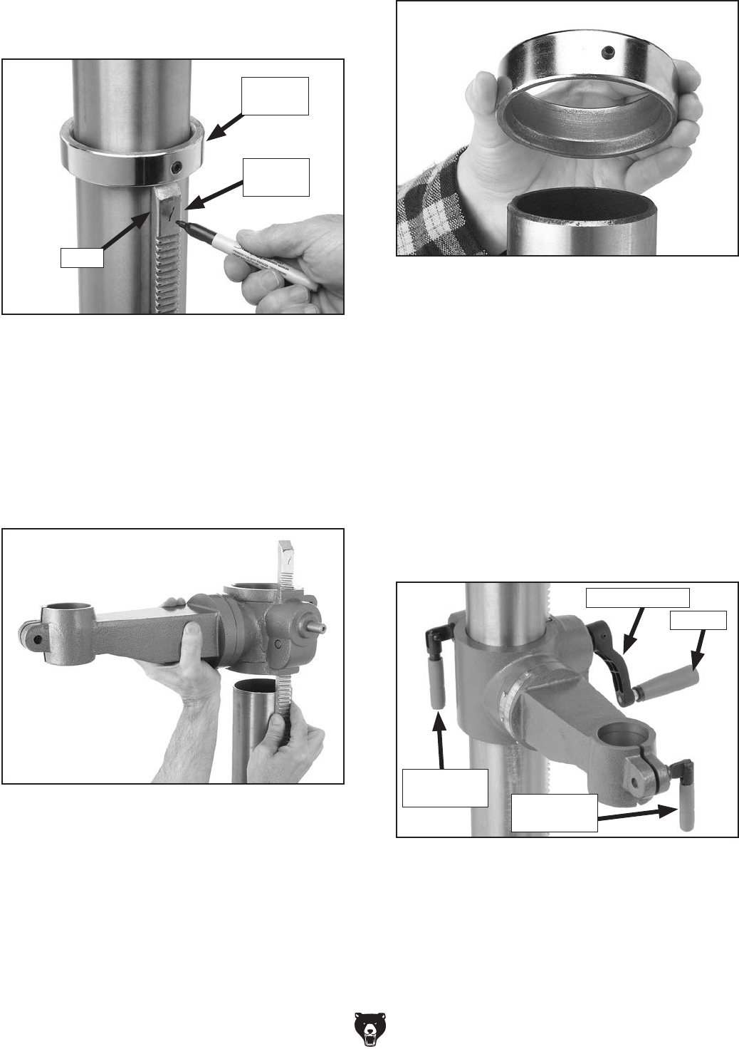
-18- Model G7943/G7944 (Mfg. 10/02+)
3. Remove the column ring by loosening the
setscrew, and remove the rack.
4. Place the rack inside of the table support
assembly, mesh it together with the pinion,
and slide the table support/rack assembly
over the column, as shown in Figure 9.
Figure 9. Sliding table support and rack over the
column.
5. Slide the column ring over the column with
the beveled edge facing down (Figure 10),
fit the beveled edge of the column ring over
the rack, and tighten the setscrew. Note: Do
not over-tighten the setscrew or you may split
the column ring. Also make sure the rack is
seated firmly in the lower ring.
Figure 10. Correct column ring orientation.
6. Install the crank lever over the pinion shaft,
and tighten the setscrew in the crank handle
against the flat part of the pinion shaft.
7. Thread the handle into the crank lever.
8. Thread the large lock lever into the back of
the table support assembly approximately
three turns, for now.
9. Thread the small lock lever into the front part
of the table support assembly approximately
three turns, for now. The assembly should
now be assembled as shown in Figure 11.
Figure 11. Handles and lock levers installed.
Large Lock
Lever
Crank Lever
Handle
Small Lock
Lever
2. Mark the top of the rack, as shown in Figure
8, to keep track of which end is up.
Figure 8. Marking top of rack to show which end
is up.
Column
Ring
Marking
Location
Rack
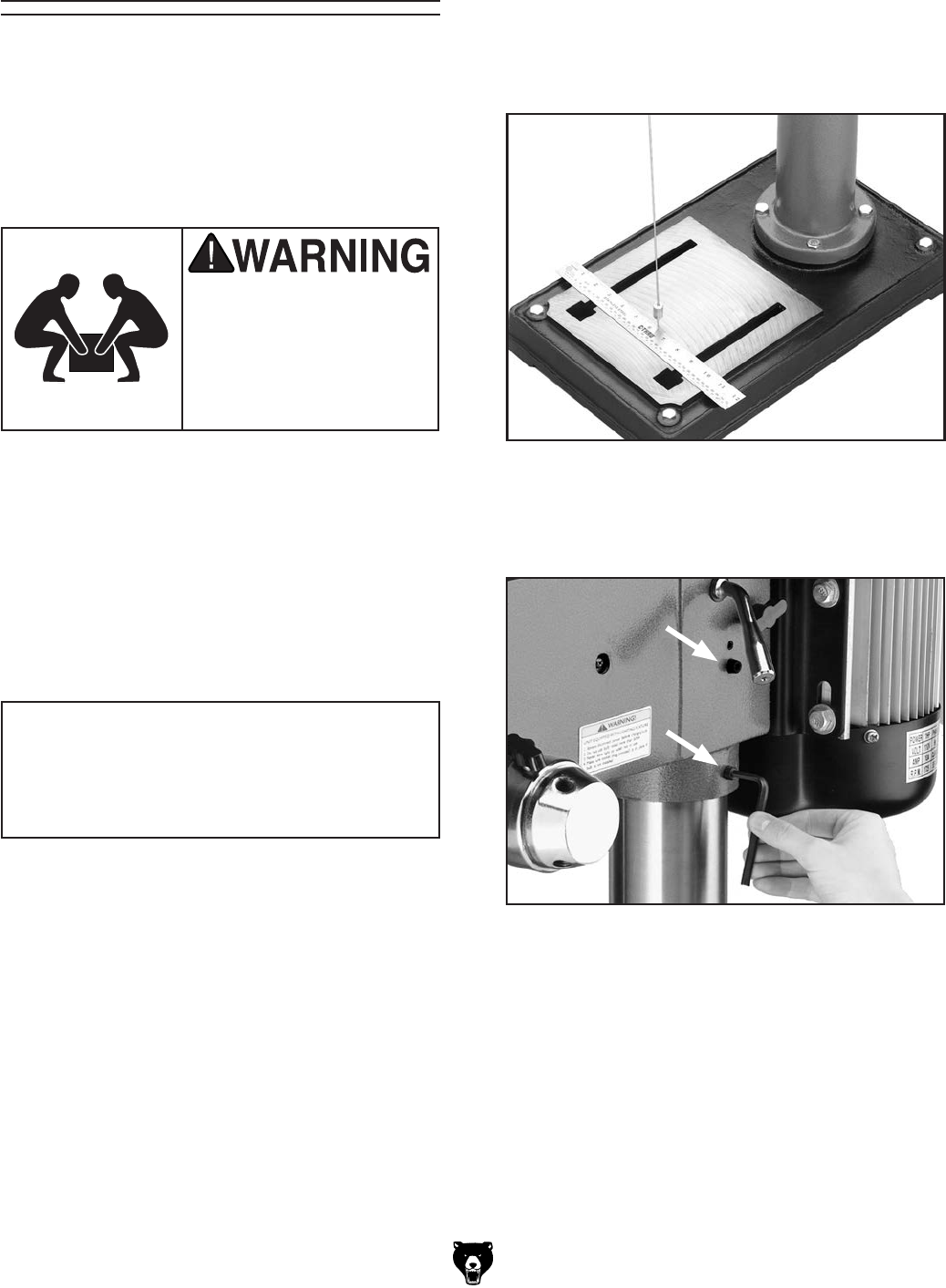
Model G7943/G7944 (Mfg. 10/02+) -19-
Components and Hardware Needed: Qty
Headstock...........................................................1
The headstock must be mounted on the col-
umn/base assembly before the drill press can be
operated. Moving and installing the headstock is
a two-person job.
Headstock
To mount the headstock onto the column:
1. Loosen the two set screws on the right side of
the headstock enough so they are flush with
the inside pocket of the headstock.
2. With the help of an assistant, lift the head-
stock assembly above the column, and gently
slide it down the column as far as it will go.
The headstock is very
heavy. You MUST have
assistance when moving,
lifting or mounting the
headstock on the column
and base assembly.
NOTICE
Do NOT force the headstock onto the col-
umn! If you do, you could damage the head-
stock and the column.
3. Suspend a plum bob from the center of the
headstock spindle so it is over the tape/ruler
as shown in Figure 12.
4. Center the headstock directly over the base
as indicated by the plum bob and ruler.
Figure 12. Aligning headstock with base.
5. Tighten the two headstock setscrews to the
column, as shown in Figure 13.
Figure 13. Securing headstock to column.
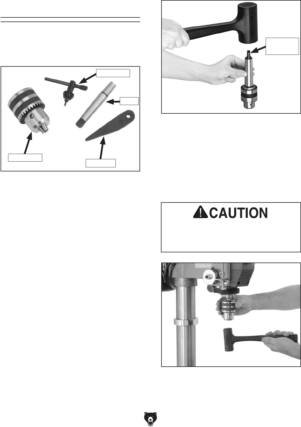
-20- Model G7943/G7944 (Mfg. 10/02+)
The drill chuck attaches to the spindle by means of
the arbor, shown in Figure 14. Matched tapers on
the arbor and the inside of the chuck create a semi-
permanent assembly when properly joined.
Figure 14. Chuck components.
Drill Chuck
Chuck Key
Arbor
Drift Key
Drill Chuck & Arbor
To assemble the drill chuck and mount it to
the spindle:
1. Use mineral spirits to thoroughly clean the drill
chuck, arbor, and spindle sockets and dry all
surfaces before assembly. Follow all safety
warnings on the container of the mineral
spirits. Failure to clean the mating surfaces
may cause the tapered fit to loosen during
operation, resulting in separation and an
unsafe condition.
2. Use the chuck key to adjust the jaws of the
drill chuck until they are inside the drill chuck
body.
3. Place the drill chuck face down on a
workbench. The arbor has a short taper and
a long taper. Place the short taper into the
socket in the back of the drill chuck and tap it
with a rubber or wooden mallet, as shown in
Figure 15. If the chuck fails to remain secure
on the arbor, repeat Steps 1 & 2.
Figure 15. Seating arbor into chuck.
Tang-Side
Up
DO NOT use a steel hammer on the drill
chuck to seat the arbor into the spindle.
You will damage the chuck and/or spindle,
which may make them unusable or unsafe.
Figure 16. Seating arbor and chuck into spindle.
4. Slide the arbor into the spindle socket while
slowly rotating the drill chuck. The socket has
a rectangular pocket where the tang (or flat
portion of the arbor shown in Figure 15) fits
into.
5. Seat the chuck with a rubber mallet, as shown
in Figure 16.
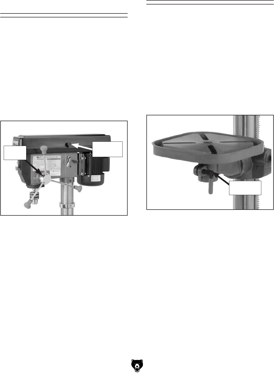
Model G7943/G7944 (Mfg. 10/02+) -21-
Figure 17. Downfeed handles and belt cover
knob installed.
Components and Hardware Needed: Qty
Downfeed Handles .............................................3
The downfeed handles must be installed to prop-
erly operate the drill press.
To install the downfeed handles:
1. Thread the handles into the spindle hub, as
shown in Figure 17, and tighten.
2. Install the belt cover knob in its place (see
Figure 17 for location).
Downfeed Handles &
Belt Cover Knob
Belt Cover
Knob
Spindle
Hub
Components and Hardware Needed: Qty
Table ...................................................................1
The table must be installed to properly support
the workpiece during operation.
To install the table:
1. Insert the table shaft into the table support
assembly.
2. Tighten the small locking lever (Figure 18) to
secure the table in the table support assem-
bly.
Table
Figure 18. Table installed.
Small Lock
Lever
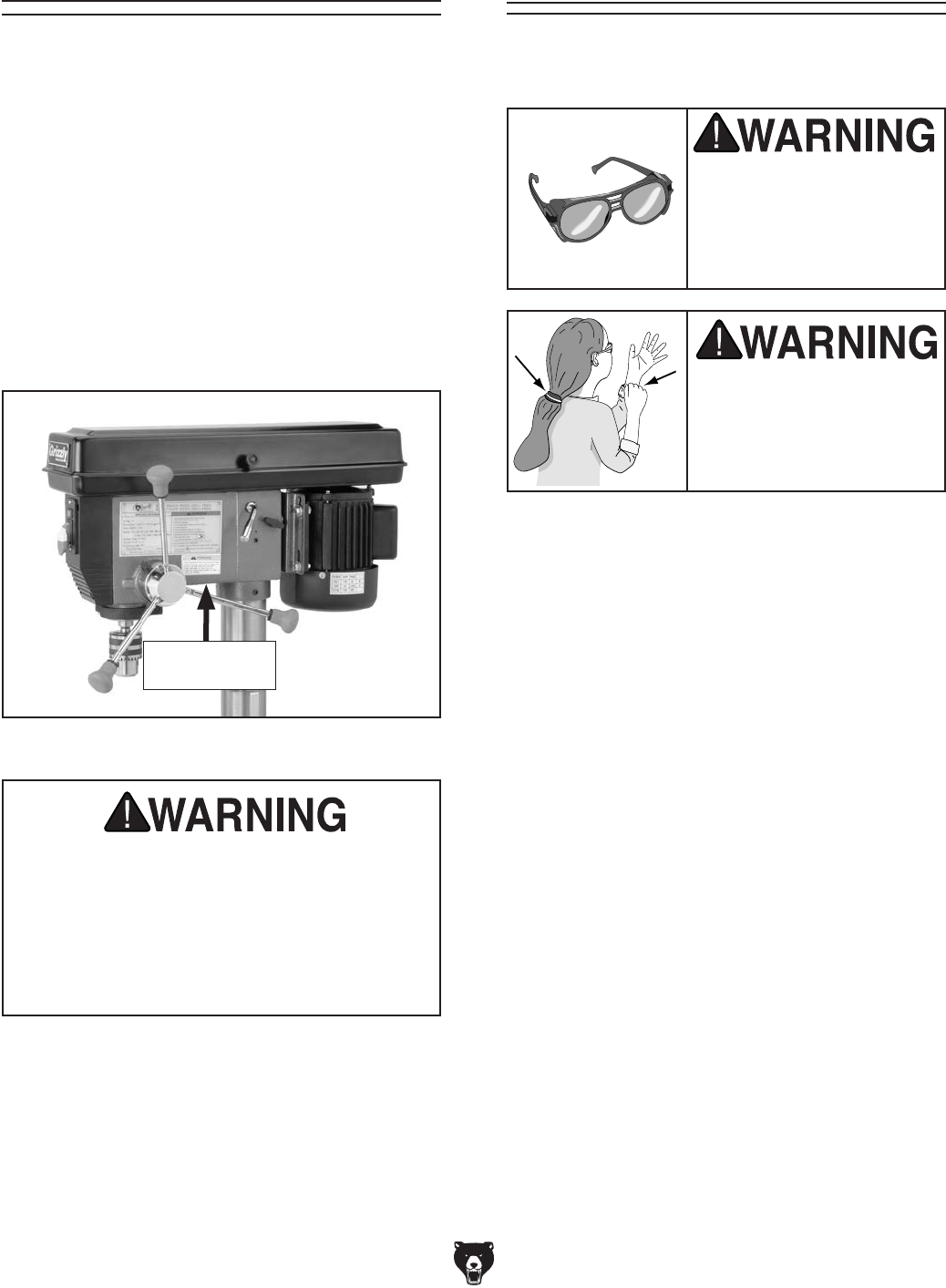
-22- Model G7943/G7944 (Mfg. 10/02+)
Components and Hardware Needed: Qty
60W Light Bulb ...................................................1
The Model G7943/G7944 includes a light socket.
When the drill press is shipped from the factory,
a dust plug is installed in the light socket for pro-
tection.
To install a light bulb in the drill press:
1. Remove the dust plug from the light socket.
2. Install a 60W or smaller light bulb in the loca-
tion shown in Figure 19.
Light
Figure 19. Light bulb access location.
Light Bulb
Access Here
Test Run
Wear safety glasses
whenever starting or
using machine. Failure
to comply may result in
serious personal injury.
Keep loose clothing
rolled up and out of the
way of machinery and
keep hair pulled back.
Once assembly is complete, you are ready to test
run the drill press.
To test run the drill press:
1. Turn the power supply ON at the main
panel.
2. With your finger poised on the paddle
switch (in case there is a problem), flip the
START button ON. The drill press should run
smoothly, with little or no vibration or rubbing
noises.
Investigate and correct for strange or unusual
noises before operating the machine further.
If you cannot easily locate the source of a
potential problem, refer to Troubleshooting
on Page 35. If you still can't solve the
problem, contact our Technical Support at
(570) 546-9663.
Use only bulbs that are “safety coated” and
shatter resistant. The bulb will be exposed
at the bottom of the head casting which
helps with illumination. Impacts with a bulb
not “safety coated” may shatter, expos-
ing the electrical filaments and creating an
electrical shock hazard.
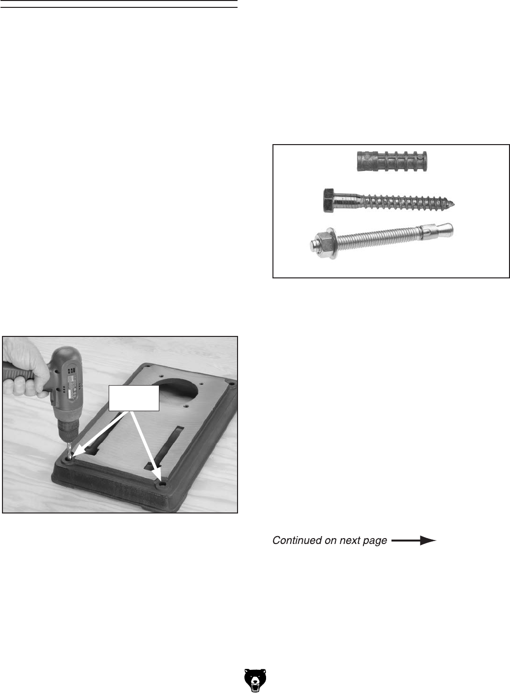
Model G7943/G7944 (Mfg. 10/02+) -23-
The Model G7943 should be secured to a bench.
The Model G7944 base should be secured to the
floor.
Bench Mounting
Components and Hardware Needed: Qty
Assembled Drill Press ........................................1
Lag Bolts 3⁄8-16 x 3 (Not Included) .....................4
Carriage Bolts M10-1.5 x 95 (Not Included) .......4
Flat Washers 10mm (Not Included) ....................4
Hex Nuts M10-1.5 (Not Included) .......................4
To mount the G7943 drill press to a table:
1. Clamp the base on a bench top capable
of holding approximately 160 lbs. plus the
weight of the workpiece using two clamps.
Make sure the surface is flat and stable.
2. Using holes in the base as a guide (Figure
20), drill and bolt the base to the bench top
using lag bolts, or carriage bolts, flat wash-
ers, and hex nuts.
Mounting Floor Mounting
Once you have confirmed that your Model G7944
is running properly, we strongly recommend
mounting it to the floor to ensure optimum
stability.
Lag shield anchors with lag bolts and anchor
studs (Figure 21) are two popular methods for
anchoring an object to a concrete floor. We sug-
gest you research the many options and methods
for mounting your machine and choose the best
that fits your specific application.
Figure 21. Typical concrete mounting hardware.
Mobile Base Mounting
Because the Model G7944 drill press is top-heavy
by nature, we recommend mounting it to the floor,
rather than a mobile base.
If you must use a mobile base, ALWAYS mount
your drill press to a base plate inside of the mobile
base, as shown in Figure 23.
A good quality base plate increases the standard
footprint of the drill press to make it much more
stable. The base plate must be at least 11⁄2" thick
and made of plywood (do not use OSB, MDF,
or particle board) to hold the weight of the drill
press. A common way for making the baseplate is
described in this sub-section.
Figure 20. Using holes as a drilling guide.
Mounting
Holes
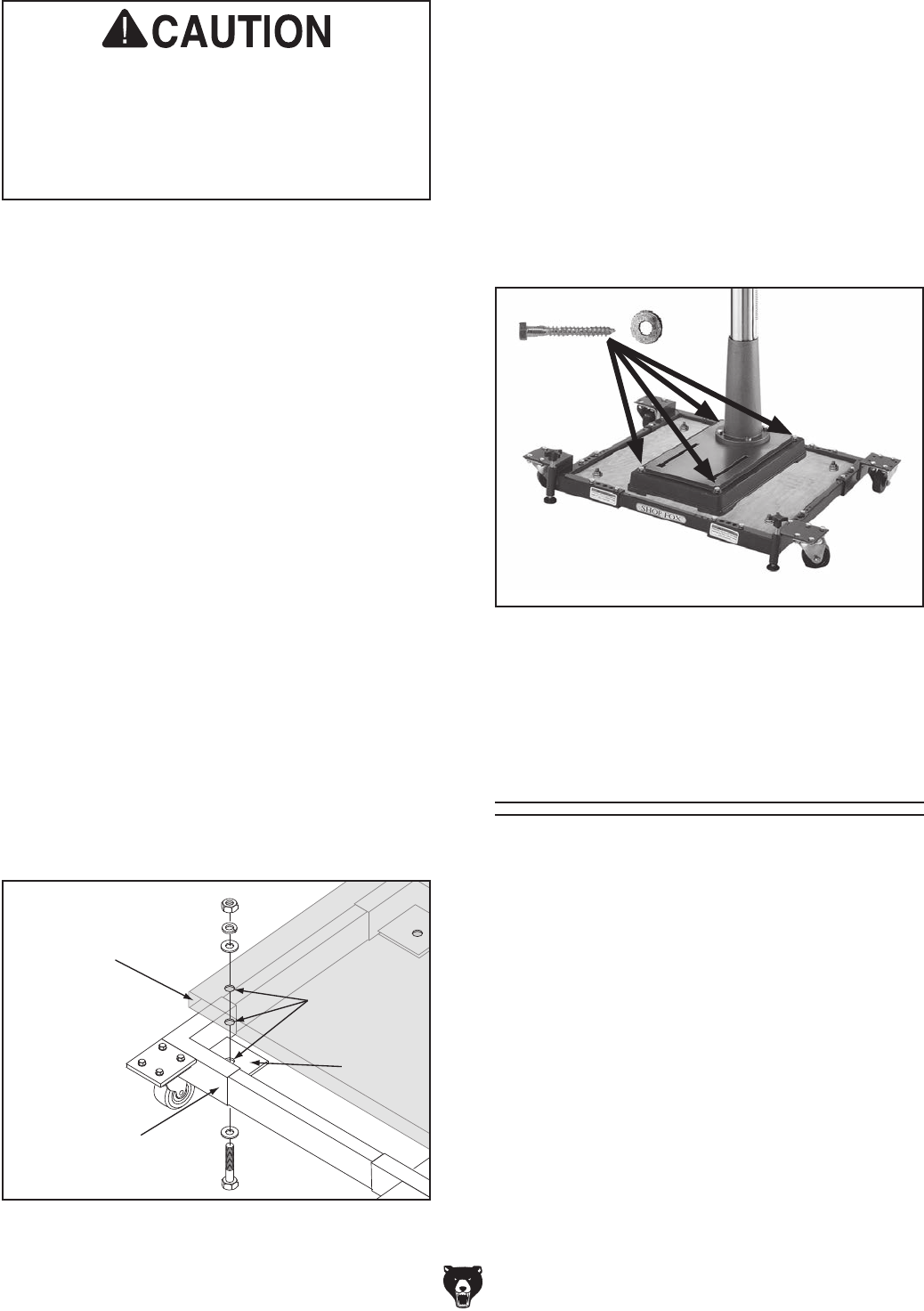
-24- Model G7943/G7944 (Mfg. 10/02+)
For your convenience, the adjustments listed
below have been performed at the factory; how-
ever, because of the many variables involved
with shipping, we recommend that you at least
verify the following adjustments before operating
your machine—this will ensure that you know the
operating tolerances of your machine, and you
have them adjusted to your expectation.
Step-by-step instructions for these adjustments
can be found in SECTION 7: SERVICE.
Factory adjustments that should be verified:
1. Depth Stop Calibration (Page 38)
2. Feed Shaft Spring Tension (Page 38)
Recommended
Adjustments
Needed Materials for Base Plate Qty
• Plywood 3⁄4" x 23
3⁄4" x 233⁄4" ........................ 2
• Wood Glue ................................. As Needed
• Wood Screws #6 x 11⁄4" ............................ 24
• Mounting Hardware ............................ Varies
To make and use the base plate:
1. Glue the two pieces of plywood together,
and align the edges and corners so the two
boards make one thick piece.
2. Use the wood screws to fasten the boards
together from both sides.
3. Allow 24 hours for the glue to dry before plac-
ing the drill press on it.
4. Place the base plate on the mobile base.
5. Drill holes through the base plate and the
metal plates at the corners of the mobile
base.
6. Secure the base plate to the mobile base with
hex bolts, hex nuts, flat washers and lock
washers, as shown in Figure 22.
Drill presses are top-heavy and must be
securely attached to a large-footprint base
plate when used with a mobile base. Failure
to use a base plate greatly increases pos-
sibility of tipping and personal injury.
Base
Plate
Mobile
Base
Metal
Plate
Mounting
Holes
Figure 22. Mounting base plate to mobile base.
Note: Use 2" to 21⁄4" long hex bolts.
7. Place the drill press on the base plate.
8. Position the drill press close to the front of the
mobile base, so the mobile base will not be a
tripping hazard.
9. Mount the drill press to the base plate with
lag bolts and flat washers (Figure 23); or with
through bolts, flat washers, and hex nuts.
Figure 23. Drill press mounted on mobile base,
using a base plate for support.
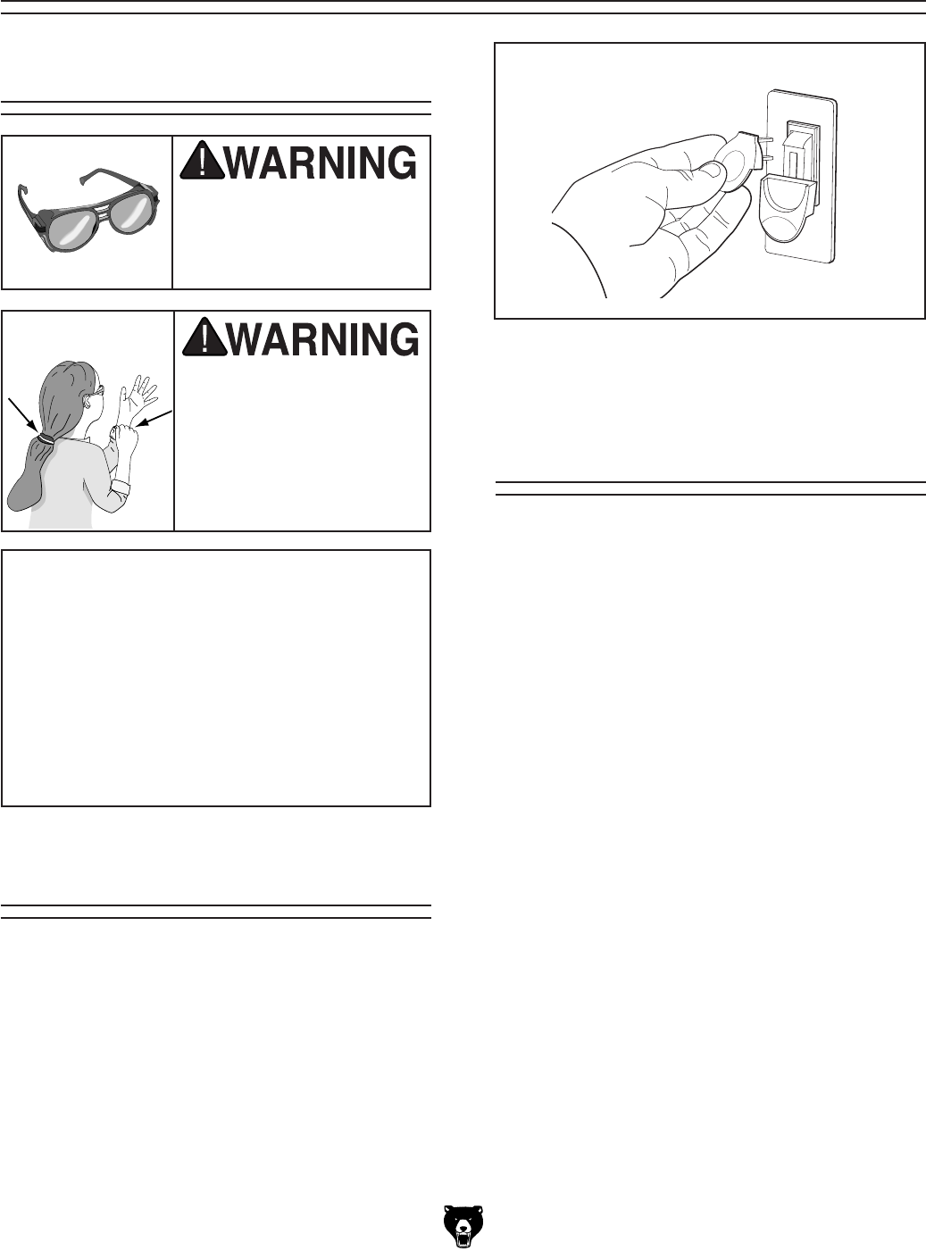
Model G7943/G7944 (Mfg. 10/02+) -25-
Loose hair and cloth-
ing could get caught in
machinery and cause seri-
ous personal injury. Keep
loose clothing and long
hair away from moving
machinery.
Installing/Removing
Drill Bits
Operation Safety
Any drill bit you install in the chuck must be tight
enough that it will not come loose during opera-
tion.
To install a drill bit:
1. UNPLUG THE DRILL PRESS!
2. Open the drill chuck wide enough to accept
the shank of the drill bit.
3. Insert the drill bit as far as possible into the
chuck WITHOUT allowing the chuck jaws to
touch the fluted portion of the bit, and hand
tighten the chuck.
Note: Make sure small bits are not trapped
between the edges of two jaws; if they are,
reinstall the drill bit or it will not be secure
enough to use for drilling.
4. Final tighten the drill bit with the chuck key.
To remove a drill bit:
1. UNPLUG THE DRILL PRESS!
2. Use the chuck key to open the drill chuck,
and catch the drill bit with a rag to protect
your hands.
SECTION 4: OPERATIONS
NOTICE
If you have never used this type of machine
or equipment before, WE STRONGLY REC-
OMMEND that you read books, trade maga-
zines, or get formal training before begin-
ning any projects. Regardless of the con-
tent in this section, Grizzly Industrial will
not be held liable for accidents caused by
lack of training.
Wear safety glasses when
operating this machine.
Serious injury may occur if
this warning is ignored!
Switch/Lockout
The ON/OFF switch can be locked-out to prevent
unauthorized use.
To use the switch:
1. To turn the drill press ON, flip the switch up.
2. To turn the drill press OFF, press the switch
down.
3. To lock-out the switch, remove the yellow key
from the switch housing, as shown in Figure
24. Place the key in a safe place.
Figure 24. Locking-out.
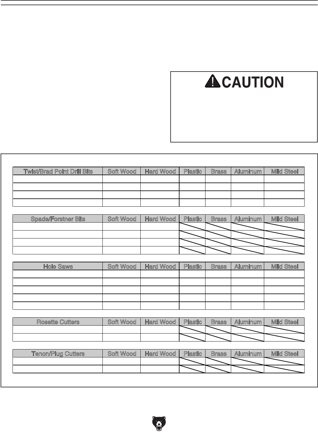
-26- Model G7943/G7944 (Mfg. 10/02+)
Choosing Speeds
Twist/Brad Point Drill Bits Soft Wood Hard Wood Plastic Brass Aluminum Mild Steel
1/16" – 3/16" 3000 2500 2500 2500 3000 2500
13/64" – 3/8" 2000 1500 2000 1250 2500 1250
25/64" – 5/8" 1500 750 1500 750 1500 600
11/16" – 1" 750 500 1000 400 1000 350
Spade/Forstner Bits Soft Wood Hard Wood Plastic Brass Aluminum Mild Steel
1/4" – 1/2" 2000 1500
9/16" – 1" 1500 1250
1-1/8" – 1-7/8" 1000 750
2–3" 500 350
Hole Saws Soft Wood Hard Wood Plastic Brass Aluminum Mild Steel
1/2" – 7/8" 500 500 600 600 600 500
1" – 1-7/8" 400 400 500 500 500 400
2" – 2-7/8" 300 300 400 400 400 300
3" – 3-7/8" 200 200 300 300 300 200
4" – 5" 100 100 200 200 200 100
Rosette Cutters Soft Wood Hard Wood Plastic Brass Aluminum Mild Steel
Carbide Insert Type 350 250
One-Piece Type 1800 500
Tenon/Plug Cutters Soft Wood Hard Wood Plastic Brass Aluminum Mild Steel
3/8" – 1/2" 1200 1000
5/8" – 1" 800 600
Using the Drill Bit Speed Chart
The chart shown in Figure 25 is intended as
a guide only. Always follow the manufacturer's
speed recommendations if provided with your
drill bits, cutters, or hole saws. Exceeding the
recommended speeds may be dangerous to the
operator.
The speeds shown here are intended to get you
started. The optimum speed will always depend
on various factors, including tool diameter, drilling
pressure, material hardness, material quality, and
desired finish.
Often, when drilling materials other than wood,
some type of lubrication is necessary.
Lubrication Suggestions
Wood ...........................................................None
Plastics ........................................... Soapy Water
Brass .............................. Water-Based Lubricant
Aluminum ......................Paraffin-Based Lubricant
Mild Steel ..............................Oil-Based Lubricant
Larger bits turning at slower speeds tend
to grab the workpiece aggressively. This
can result in the operator's hand being
pulled into the bit or the workpiece being
thrown with great force. Always clamp the
workpiece to the table to prevent injuries.
Figure 25. Drill bit speed chart.
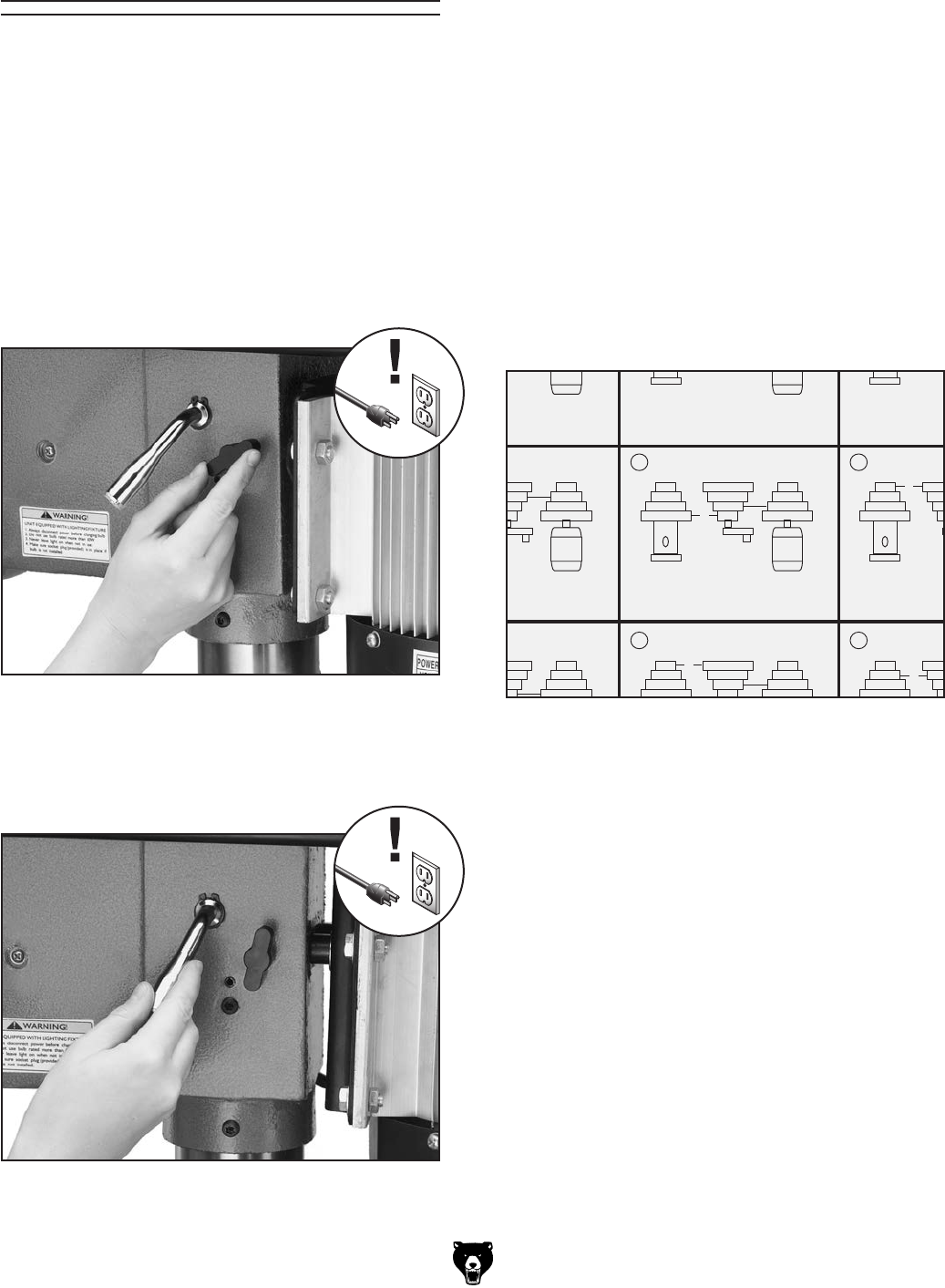
Model G7943/G7944 (Mfg. 10/02+) -27-
D
C
B
A
4
3
2
1
4
3
2
1
1 RPM 210
BELT:A-1,4-4
D
C
B
A
4
3
2
1
4
3
2
1
2 RPM 260
BELT:B— 2,4–4
D
C
B
A
4
3
2
1
4
3
2
1
3 RPM 320
BELT:A—1,3–3
D
C
B
A
4
3
2
1
4
3
2
1
4 RPM 440
BELT:C-3.4-4
D
C
B
A
4
3
2
1
4
3
2
1
5 RPM 480
BELT:B-2,3-3
D
C
B
A
4
3
2
1
4
3
2
1
6 RPM 540
BELT:A— 1,2–2
D
C
B
A
4
3
2
1
4
3
2
1
7 RPM 980
BELT:D— 4,3–3
D
C
B
A
4
3
2
1
4
3
2
1
8 RPM 1430
BELT:C-3.2-2
D
C
B
A
4
3
2
1
4
3
2
1
9 RPM 1510
BELT:B-2.1-1
D
C
B
A
4
3
2
1
4
3
2
1
RPM 1650
BELT:D-4.2-2
D
C
B
A
4
3
2
1
4
3
2
1
RPM 2180
BELT:C-3.1-1
D
C
B
A
4
3
2
1
4
3
2
1
RPM 3050
BELT:D-4.1-1
10 11
12
Figure 26. Loosening lock knob (both sides).
Figure 27. Using the belt tension lever.
The belts in the head of the drill press must be
rearranged to change speeds. A chart under the
belt cover shows the belt positions needed to
make the drill press run at the desired speed.
To change speeds:
1. UNPLUG THE DRILL PRESS!
2. Loosen the belt tension lock knobs (shown in
Figure 26) on both sides of the headstock,
so the motor is free to move.
Changing Speeds
3. Rotate the belt tension lever clockwise, as
shown in Figure 27, to take tension off the
V-belts.
4. Locate the desired speed on the speed chart
under the belt cover and move the V-belts
to the desired V-grooves on the motor, idler,
and spindle pulleys.
For Example: As indicated in the speed chart
for 540 RPM (Figure 28), a belt combination
of A-1, 2-2 creates 540 RPM.
• The “A-1” refers to the belt position between
the spindle pulley and the idler pulley.
• The “2-2” refers to the belt position between
the motor pulley and the idler pulley.
Note: Both belts may have to be removed
before certain speed changes can be made.
Figure 28. Pulley combination for 540 RPM for
example.
5. Rotate the belt tension lever until the belts
are tight. Tighten both lock knobs.
6. Close the cover before plugging in the
machine.

-28- Model G7943/G7944 (Mfg. 10/02+)
The Model G7943/G7944 is designed for drilling
holes in wood or metal. The basic operation
of a drill press is lining up your drill bit with the
intended hole location, turning the drill press
ON, and using the down feed levers to move the
spinning drill bit into the workpiece.
For safe operation and optimum results, it
is very important to follow these guidelines
when drilling:
CLEARING CHIPS: Raise the drill bit often to
clear chips and cool the drill bit. This will ease the
work of the drill press motor and extend the life of
your drill bits.
SECURING WORKPIECE TO TABLE: Secure
the workpiece to the table or in a vise that is
secured to the table before drilling.
PROTECTING TABLE: Protect the table by plac-
ing the workpiece on scrap wood, or center the
location of the hole to be drilled over the pocket in
the table when through drilling. Also, make use of
the depth stop so that the drill bit goes no deeper
than necessary.
USING CORRECT SPEEDS: Use the correct
speed for the diameter of the drill bit being used
and the type of material being drilled. Refer to the
Drill Bit Speed Chart on Page 26 to help you
choose the correct speed for your application.
LARGE DIAMETER BITS: Large diameter drill
bits require slower spindle speeds.
SMALL DIAMETER BITS: Smaller diameter drill
bits require faster spindle speeds.
HARD MATERIAL: The harder the material,
(steel vs. wood) the slower the spindle speed.
Drilling
Larger bits turning at slower speeds tend
to grab the workpiece aggressively. This
can result in the operator's hand being
pulled into the bit or the workpiece being
thrown with great force. Always clamp the
workpiece to the table to prevent injuries.
SOFT MATERIAL: The softer the material, the
faster the spindle may turn. (Plastics can melt at
too high of a spindle speed!)
LUBRICANT: Use some form of lubricant on
all materials except wood. Refer to Lubrication
Suggestions on Page 26 to find the correct lubri-
cation for your application.
DRILLING ACCURACY: To prevent drill bit wan-
dering and ensure accurate placement of holes,
mark the hole location with a center punch before
drilling. Also consider using a center-point drill to
start the hole.
PLUG/ROSETTE CUTTERS: Plug cutters and
rosette cutters are for wood only. However, car-
bide-tipped bits and cutters cut at a higher speed
and can cut materials other than wood, depending
on the cutter type.
5-FLUTE/2-FLUTE CUTTERS: Use a 5-flute cut-
ter when cutting into plastics, brass, aluminum,
and mild steel. A 2-flute cutter can aggressively
grab the workpiece and damage the tool if used
with materials other than wood.
SPADE BITS AND PLASTIC: When drilling plas-
tic with a spade bit, use a spade bit with spurs.
HOLE SAWS: When using hole saws, apply firm
and even pressure, so the saw teeth contact the
surface all at the same time—not at an angle. You
can also flip the workpiece and finish drilling from
the other side.
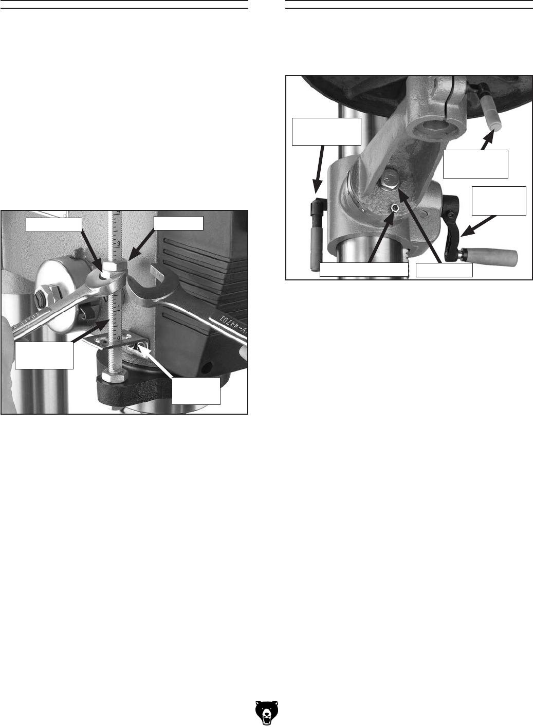
Model G7943/G7944 (Mfg. 10/02+) -29-
Figure 29. Depth stop components.
Depth Nut Jam Nut
Depth
Stop Stud
The Model G7943/G7944 has a depth stop that
allows you to drill repeated non-through holes to
the same depth every time.
The depth stop consists of a stud attached to the
quill with two hex nuts that can be lowered or
raised on the stud so the lower nut (depth nut)
hits a stop bracket when the drill bit is lowered.
The upper hex nut (jam nut) is then used to
tighten against the depth nut to secure it in place
so it doesn't move with repeated operations.
Figure 29 shows the various components of the
depth stop.
Depth Stop
To set the depth stop:
1. Lower the drill bit to the required height.
2. Thread the depth nut down against the stop
bracket.
3. Lower the jam nut against the depth nut.
4. Using wrenches, hold the depth nut in place
and tighten the jam nut against the depth
nut.
Note: The scale on the depth stop can be recali-
brated if it gets moved or has changed since the
factory setting. Refer to Calibrating Depth Stop
on Page 38 for instructions on how this is done.
Stop
Bracket
The table can raised/lowered, rotated, and tilted
90° left or right. Table adjustment controls are
shown in Figure 30.
Adjusting Table
Figure 30. Table adjustment controls.
Large Lock
Lever
Location Pin Nut
Crank
Lever
Small Lock
Lever
Table Height
1. Loosen the large lock lever.
2. Adjust the height.
3. Lock the large lock lever.
Table Rotation
1. Loosen the small lock lever.
2. Rotate the table as necessary.
3. Lock the small lock lever.
Table Tilt
1. Tighten the location pin nut to draw the loca-
tion pin out of the hole. Note: The location
pin is friction fit in the hole to lock the table at
0°. When reinstalling, set the table to 0°, back
the nut off, and tap the pin back in the hole.
2. Loosen the lock bolt and tilt the table to the
desired angle (make sure the small lock lever
is locked, so the table won't fall out).
3. Tighten the lock nut bolt.
Lock Bolt
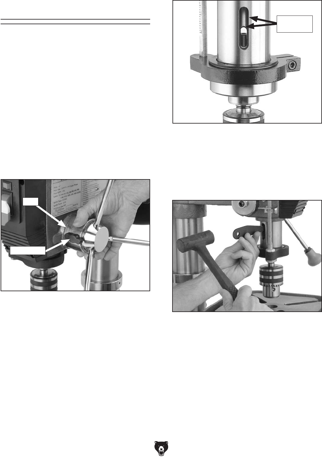
-30- Model G7943/G7944 (Mfg. 10/02+)
Figure 32. Inner and outer drift-key slots
aligned.
Figure 33. Using drift key to remove arbor.
Both Slots
Aligned
The arbor can be removed to install another drill
chuck in the spindle. A drift key is included to help
remove the arbor from the spindle. Usually, once
the chuck and arbor have been properly mounted
together, they are considered semi-permanent
connections. (If you would like to install a differ-
ent chuck, we recommend getting a new arbor for
that chuck.)
To remove the drill chuck and arbor:
1. UNPLUG THE DRILL PRESS!
2. Rotate the spindle handles until the drift-key
slot is exposed in the side of the quill.
3. Loosen the lock knob and rotate the hub
(Figure 31) clockwise until it stops.
Arbor Removal
7. Insert the drift key into the drift-key slot.
8. Tap the drift key with a rubber or wooden
mallet, as shown in Figure 33, until the
chuck releases.
4. Tighten the lock knob. The quill should not
return up into the head casting.
5. Move the table up until it is 1⁄4" below the bot-
tom of the chuck, and place a towel or cloth
under the chuck.
6. Rotate the spindle until the inner drift-key slot
is aligned with the outer slot, as shown in
Figure 32. You will see through the spindle
when the slot is properly aligned.
Figure 31. Rotating hub.
9. Hold a downfeed handle with one hand, and
loosen the lock knob with the other hand.
10. Carefully retract the quill into the headstock.
Hub
Lock Knob
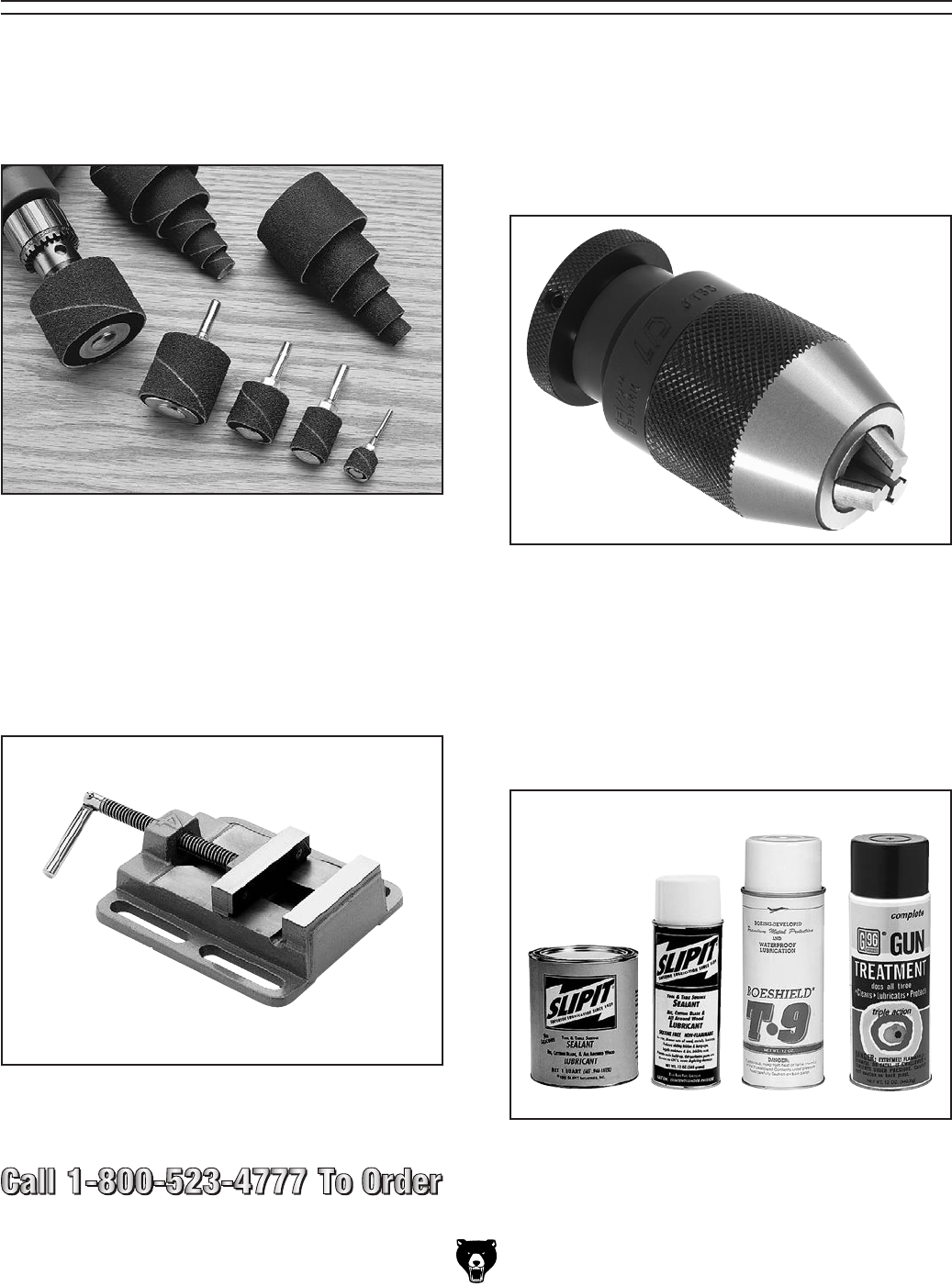
Model G7943/G7944 (Mfg. 10/02+) -31-
SECTION 5: ACCESSORIES
Figure 36. Model G8581 1⁄2" Keyless Drill Chuck
JT #33.
G8581—1⁄2" Keyless Drill Chuck JT #33
Industrial grade keyless chucks are excellent for
quick bit changes. Knurled grips and exceptional
accuracy make these chucks an indispensable
part of any shop. Use on drill presses, lathe tail-
stocks and milling machines. 0 – 1⁄2" capacity with
a Jacobs Taper #33 in back.
G2500—20-PC Regular Sanding Drum Set
Use on your drill press, lathe, or hand drill. This kit
consists of 5 drums in popular 1⁄2" x 1⁄2", 3⁄4" x 1",
1"x 1", 11⁄2" x 11⁄2", and 2" x 11⁄2" sizes. Comes with
50, 80 and 120 grit sizes for each drum.
Figure 34. Model G2500 20-PC Sanding Drum
Set.
G5753—Drill Press Vise 6"
If you use a drill press and value your fingers, you
need one of these. Made from high-grade cast
iron, these hefty horizontal vises offer support
and stability, allowing you to keep your hands well
away from fast moving bits and cutters.
Figure 35. Model G5753 Drill Press Vise 6".
Figure 37. Recommended products for protect-
ing unpainted cast iron/steel areas.
G5562—SLIPIT® 1 Qt. Gel
G5563—SLIPIT® 12 oz Spray
G2871—Boeshield® T-9 12 oz Spray
G2870—Boeshield® T-9 4 oz Spray
H3788—G96® Gun Treatment 12 oz Spray
H3789—G96® Gun Treatment 4.5 oz Spray
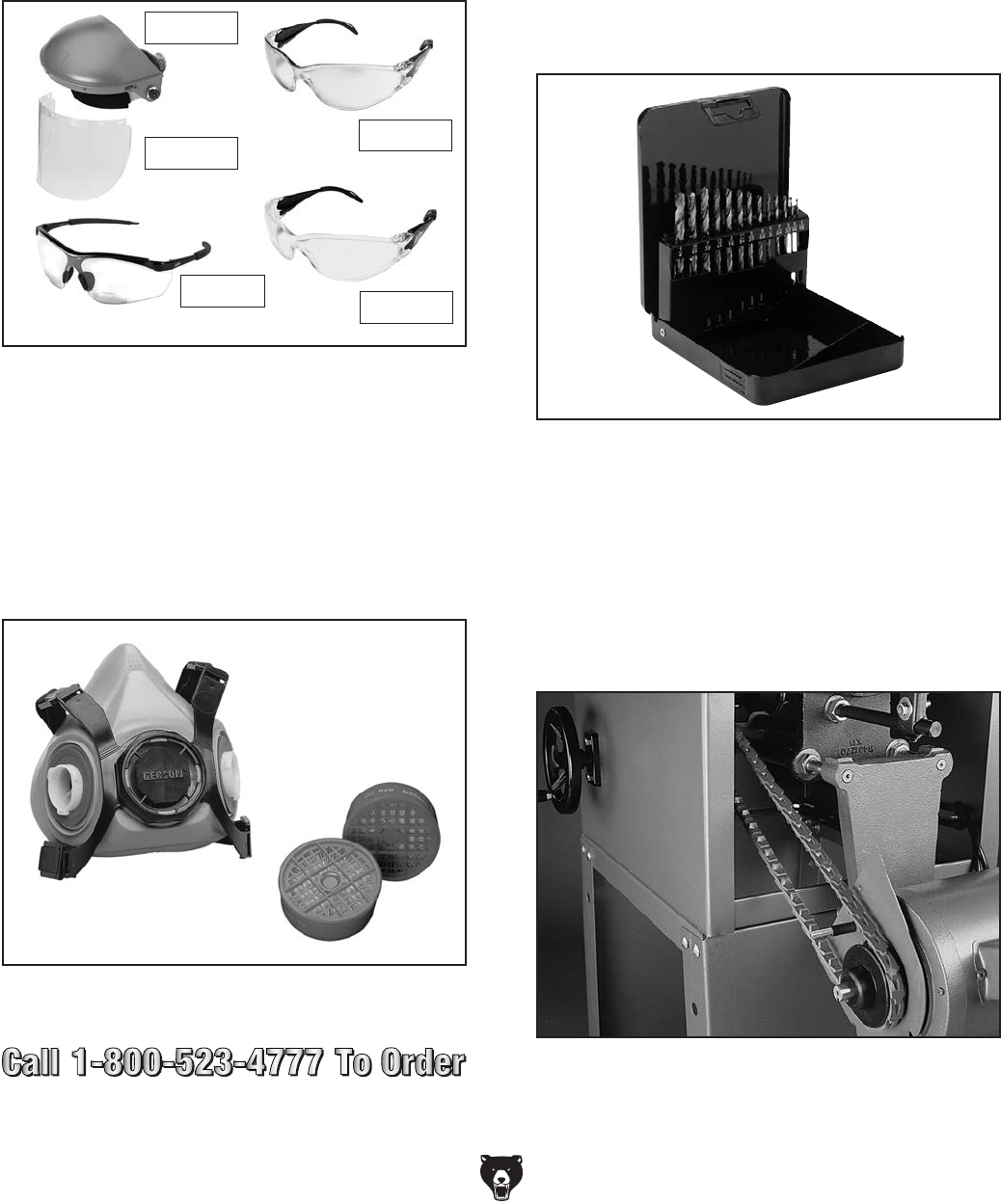
-32- Model G7943/G7944 (Mfg. 10/02+)
Figure 40. Model G8865 13-PC Alloy Drill Bits.
G8865—Cobalt Alloy Drill Bits 13-PC. Set
G8866—Steelex® Cobalt Alloy Drill Bits 21-PC
Set
G8867—Steelex® Cobalt Alloy Drill Bits 29-PC
Set
Cobalt Alloy bits will retain their edge sharpness
longer than normal HSS bits, resulting in a signifi-
cant saving of time and money in the workshop.
Includes a heavy-gauge steel index case for
storing. G8865: 1⁄16" -1⁄4"; G8866: 1⁄16"- 3⁄8"; G8867:
1⁄16"-1⁄2".
G3639—Power Twist® V-Belt 3⁄8" x 48"
Smooth running with less vibration and noise
than solid belts. The Power Twist® V-belts can
be customized in minutes to any size—just add
or remove sections to fit your needs. Size: 3⁄8" x
48"; replaces all "M" sized V-belts. Requires two
Power Twist® V-belts to replace the stock V-belts
on your Model G7943/G7944. Well worth it!
Figure 41. G3639 Power Twist® V-Belt installed.
Figure 39. Half-mask respirator with disposable
cartridge filters.
H2499—Small Half-Mask Respirator
H3631—Medium Half-Mask Respirator
H3632—Large Half-Mask Respirator
H3635—Cartridge Filter Pair P100
Wood dust has been linked to nasal cancer and
severe respiratory illnesses. If you work around-
dust everyday, a half-mask respirator can be a
lifesaver. Also compatible with safety glasses!
T20501—Face Shield Crown Protector 4"
T20502—Face Shield Crown Protector 7"
T20503—Face Shield Window
T20452—"Kirova" Anti-Reflective S. Glasses
T20451—"Kirova" Clear Safety Glasses
H7194—Bifocal Safety Glasses 1.5
H7195—Bifocal Safety Glasses 2.0
H7196—Bifocal Safety Glasses 2.5
Figure 38. Eye protection assortment.
T20451
T20452
T20502
T20503
H7194
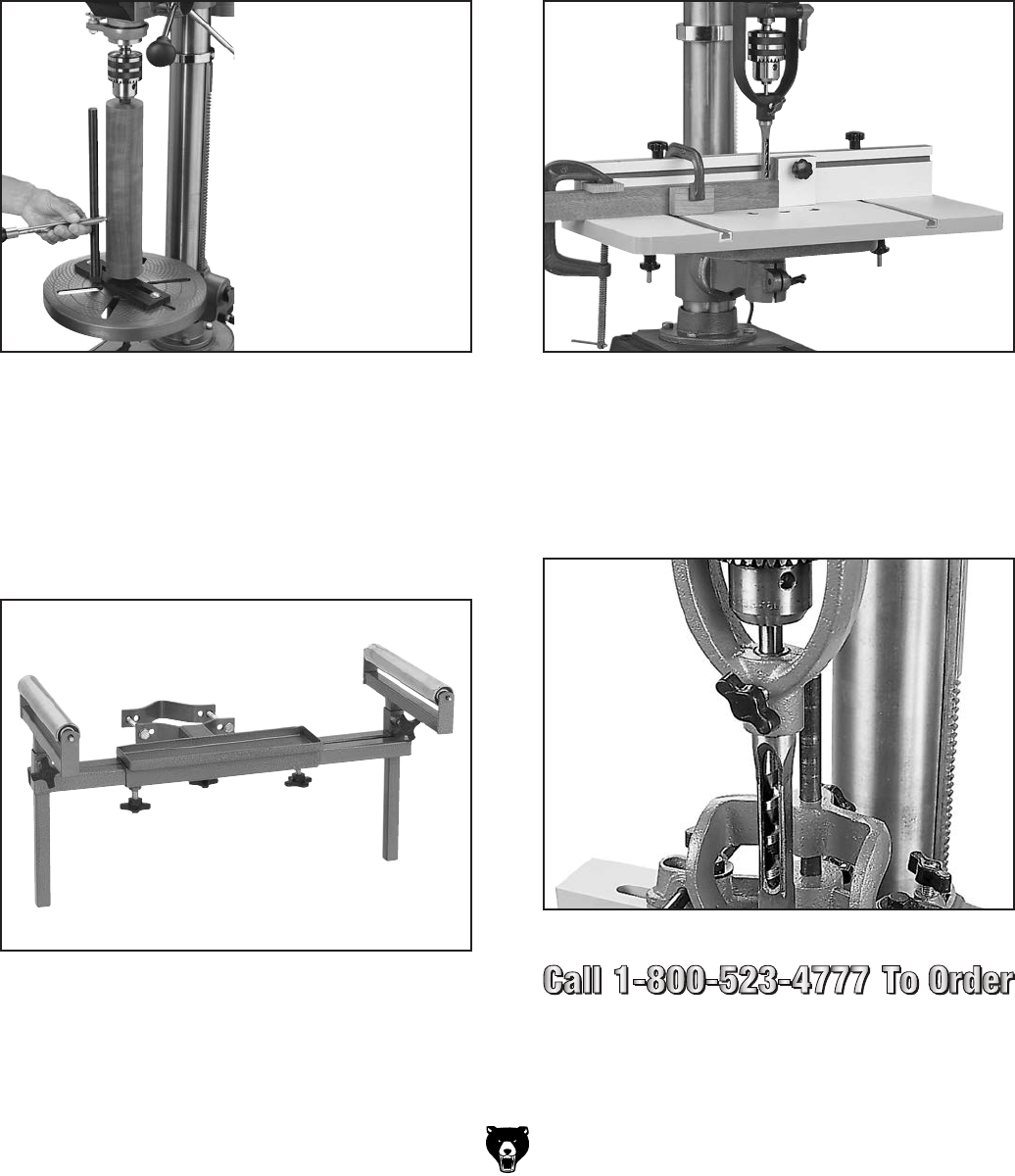
Model G7943/G7944 (Mfg. 10/02+) -33-
Figure 42. Model H8071 Lathe Attachment.
H8071—Lathe Attachment for Drill Press
Perform vertical spindle turning on your multi-
speed drill press with this Lathe Attachment. Easy
setup means quick change over from drill press
mode to lathe mode. A 12" tool rest allows a
maximum work piece length of 24" when the work
piece is reversed. Includes a base plate with live
center, 12" tool rest, mounting bolts, mini screw
center and spur center. Fits all drill presses with a
through hole in the table.
H7827—Drill Press Table
Add this 233⁄4" wide x 117⁄8" deep Drill Press Table
with 3" high fence and stop block to your drill
press for greater work support and increased
accuracy. The fence and stop block slide along
T-slots for quick, yet secure set-up and a remov-
able 315⁄16" square center block allows thru drilling
past the table. Fits all standard drill press tables
and includes two universal table clamps. Mortising
chisel and clamps not included.
Figure 44. Model H7827 Drill Press Table.
G1083—Mortising Attachment
A mortising attachment and chisel lets you drill
square holes in wood. The attachment holds the
sharp cornered chisel in place while the inner drill
cuts out the center. Drills have 1⁄2" shank.
Figure 45. Model G1083 Mortising Attachment.
H6238—Drill Press Roller Supports
This Drill Press Roller Support provides stability
and control for longer work. Rollers clamp to the
column and measure 91⁄2" wide x 13⁄8" diameter.
Lateral adjustment range is 8" minimum to 24"
maximum on each side and vertical adjustment
is 8".
Figure 43. Model H6238 Roller Supports.

-34- Model G7943/G7944 (Mfg. 10/02+)
Always disconnect power
to the machine before
performing maintenance.
Failure to do this may
result in serious person-
al injury.
Cleaning the Model G7943/G7944 is relatively
easy. Vacuum excess wood chips and sawdust,
and wipe off the remaining dust with a dry cloth.
If any resin has built up, use a resin dissolving
cleaner to remove it. Treat all unpainted cast
iron and steel with a non-staining lubricant after
cleaning.
Cleaning
SECTION 6: MAINTENANCE
Protect the unpainted cast iron surfaces by wip-
ing them clean after every use—this ensures
moisture from wood dust does not remain on bare
metal surfaces.
Keep these surfaces rust-free with regular appli-
cations of products like G96® Gun Treatment,
SLIPIT®, or Boeshield® T-9 (see SECTION 5:
ACCESSORIES on Page 31 for more details).
Unpainted Cast Iron
Lubrication
V-Belts
Since all bearings are shielded and permanently
lubricated, simply leave them alone until they
need to be replaced. DO NOT lubricate them.
Keep quill, spindle, column, and table top well
lubricated to prevent rust.
Inspect regularly for tension and wear. Check
pulleys to ensure that they are properly aligned.
See Changing Speeds on Page 26 for more
information about removing/installing belts if you
need help replacing the belts.
Regular periodic maintenance on your drill press
will ensure optimum performance. Make a habit
of inspecting your machine each time you use it.
Check for the following conditions and repair or
replace when necessary:
• Loose mounting bolts.
• Worn switch.
• Worn or damaged cords and plugs.
• Damaged V-belt.
• Any other condition that could hamper the
safe operation of this machine.
General
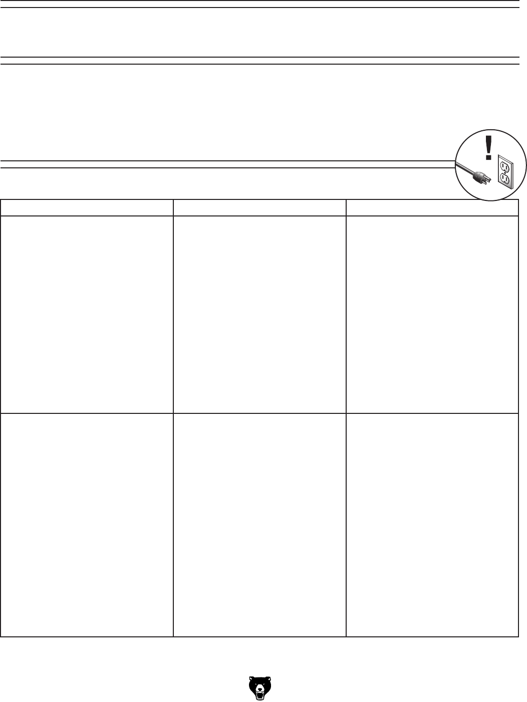
Model G7943/G7944 (Mfg. 10/02+) -35-
This section is provided for your convenience—it is not a substitute for the Grizzly Service Department. If
you need help troubleshooting, you need replacement parts, or you are unsure of how to perform the pro-
cedures in this section, then feel free to call our Technical Support at (570) 546-9663.
SECTION 7: SERVICE
About Service
Symptom Possible Cause Possible Solution
Machine does not start or a breaker trips. 1. Plug or receptacle is at fault or wired
incorrectly.
2. Start capacitor is faulty.
3. Motor connection is wired incorrectly.
4. Power supply is faulty, or is switched
OFF.
5. Safety switch key is at fault.
6. ON/OFF switch is faulty.
7. Cable or wiring is open or has high
resistance.
8. Motor is at fault.
1. Test power plug and receptacle for
good contact and correct wiring.
2. Replace capacitor.
3. Correct motor wiring (see Page 42).
4. Make sure all hot lines and grounds are
operational and have correct voltage
on all legs.
5. Install or replace safety key, or replace
switch assembly.
6. Replace faulty switch.
7. Troubleshoot wires for internal or exter-
nal breaks, check for disconnected or
corroded connections and repair or
replace wiring.
8. Test, repair or replace motor.
Machine stalls or is underpowered. 1. Incorrect spindle speed for task.
2. Machine is undersized for the task.
3. Bit or cutter is dull.
4. Low power supply voltage.
5. Belt(s) is slipping.
6. Plug or receptacle is at fault.
7. Motor connection is wired incorrectly.
8. Pulley is slipping on shaft.
9. Motor bearings are at fault.
10. Motor has overheated.
11. Motor is at fault.
1. Decrease spindle speed.
2. Use smaller drill bits/cutters and reduce
the feed rate and spindle speed.
3. Sharpen/replace bit or cutter.
4. Make sure hot lines and grounds are
operational w/correct voltage.
5. Replace bad belts, align pulleys, and
re-tension.
6. Test power plug and receptacle for
good contact and correct wiring.
7. Correct motor wiring (see Page 42).
8. Replace loose pulley and shaft.
9. Rotate motor shaft for noisy or burnt
bearings, repair/replace as required.
10. Clean inside/outside of motor, let cool,
and reduce workload on machine.
11. Test, repair or replace motor.
Troubleshooting
Motor & Electrical
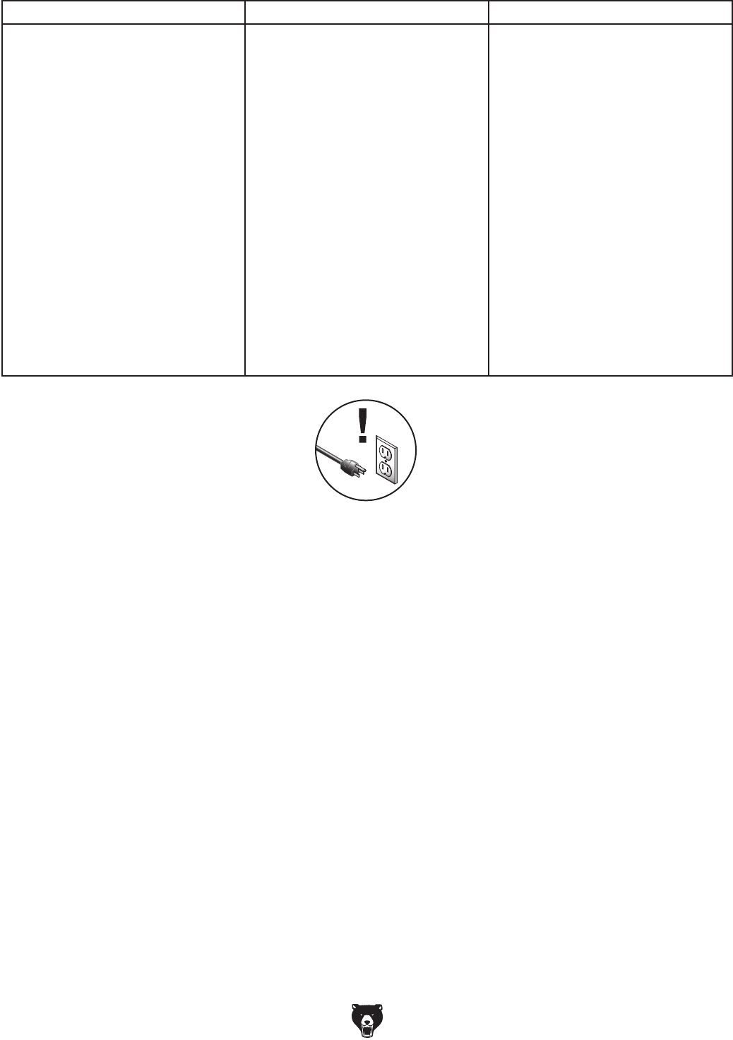
-36- Model G7943/G7944 (Mfg. 10/02+)
Symptom Possible Cause Possible Solution
Machine has vibration or noisy operation. 1. Motor or component is loose.
2. Belts are slapping belt cover.
3. V-belt(s) is worn or is loose.
4. Motor fan is rubbing on fan cover.
5. Pulley is loose.
6. Machine is incorrectly mounted to the
floor, or the floor is uneven.
7. Chuck or cutter is at fault.
8. Motor bearings are at fault.
9. Spindle bearings at fault.
1. Inspect, replace for stripped or dam-
aged bolts/nuts, and re-tighten with
thread locking fluid.
2. Replace/realign belts with a new
matched set, and retension belts (refer
to Page 27).
3. Replace belts.
4. Replace/repair dented fan cover, and
replace loose or damaged fan.
5. Remove pulley, replace with key as
required, and re-install securely.
6. Make sure floor mounting hardware is
tight; place shims under machine.
7. Replace out-of-round chuck, replace or
resharpen cutter, use appropriate feed
rate and cutting RPM.
8. Check bearings, replace motor or bear-
ings as required.
9. Replace bearing.
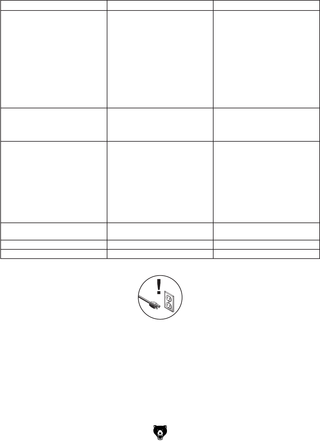
Model G7943/G7944 (Mfg. 10/02+) -37-
Symptom Possible Cause Possible Solution
Drilling stops, but the motor still oper-
ates.
1. The belt is loose or worn.
2. The pulley for the spindle shaft or the
motor is slipping on the shaft.
3. Bit slips in chuck.
1. Replace and/or adjust the belt.
2. To resecure the pulley, do these
steps:
a. UNPLUG THE DRILL PRESS!
b. Remove the setscrew on the slipping
pulley.
c. Align the flats on the pulley shaft with
the setscrew hole.
d. Reinstall and tighten the setscrew.
3. Tighten bit; inspect bit for burrs or other
obstructions that might interfere with
clamping surface.
The chuck wobbles or is loose on the
spindle shaft.
1. Foreign material is stuck between the
chuck-to-spindle mating surface.
2. Damaged chuck.
1. Remove the chuck and clean and de-
burr the tapered chuck and spindle
mating surfaces, then reassemble.
2. Replace.
The spindle does not retract completely
in the uppermost position or it binds.
1. The quill shaft is gummy with sawdust
and oil.
2. The feed shaft return spring is weak.
3. The quill deflection screw is binding the
quill.
1. Clean the gummy substance with pen-
etrating oil and lubricate with a light
coat of oil.
2. Increase the feed shaft return spring
tension as described on Page 38.
3. Loosen the jam nut, and slightly turn
out the screw where the quill binds.
Retighten the jam nut and recheck for
binding and looseness at all spindle
locations.
The quill has excessive deflection. 1. The quill shaft is at fault.
2. The quill and/or bearings are worn.
1. Adjust the quill screw.
2. Replace the quill and/or bearings.
Holes drilled at an angle. 1. Table is not at 90 degrees. 1. Adjust table angle (see Page 29).
Drill bit wobbles, holes are oversized. 1. Drill bit installed incorrectly. 2. Remove drill bit and reinstall.
Drill Press Operations
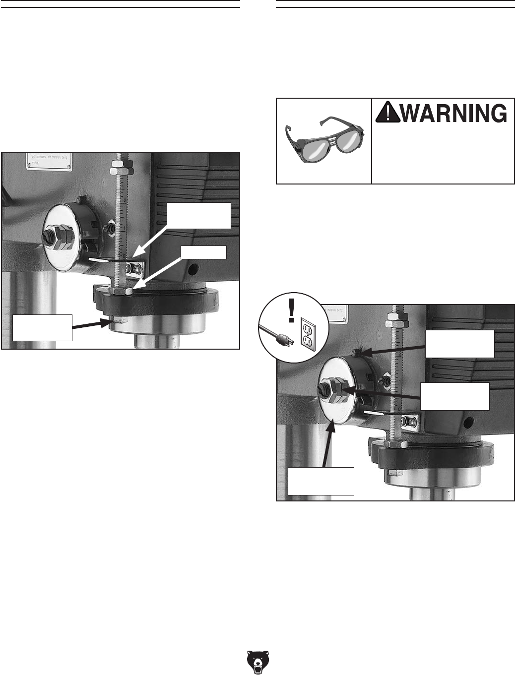
-38- Model G7943/G7944 (Mfg. 10/02+)
Figure 46. Depth stop assembly.
Calibration
Nut
Jam Nut
Stop
Bracket
The drill press comes fitted with a depth stop
to use when drilling multiple holes at the same
depth. The scale on this depth stop can be
calibrated if it ever becomes incorrect.
To calibrate the depth stop:
1. Loosen the jam nut and calibration nut shown
in Figure 46.
Depth Stop
Calibration
2. Use the calibration nut to zero the depth stop
scale with the stop bracket.
3. Hold the depth stop at zero, and tighten the
jam nut to hold the depth stop in position.
4. Test the depth stop by measuring how far the
spindle actually moves with respect to where
you set the depth stop.
Feed Shaft Spring
Tension
The feed shaft return spring is adjusted at the
factory; however, during the life of the drill press
you may want to adjust the feed shaft return
spring so the feed shaft return pressure suits your
operating needs.
Figure 47. Feed shaft return spring assembly.
Wear safety glasses when
adjusting springs. Serious
injury may occur if this
warning is ignored!
To adjust the feed shaft spring tension:
1. UNPLUG THE DRILL PRESS!
2. Wipe off any oil on the spring lock cover so it
does not slip in your fingers when you hold the
cover from spinning (see Figure 47).
Spring Cover
Lock Slot
Spring Lock
Cover
Jam Nut and
Cover Nut
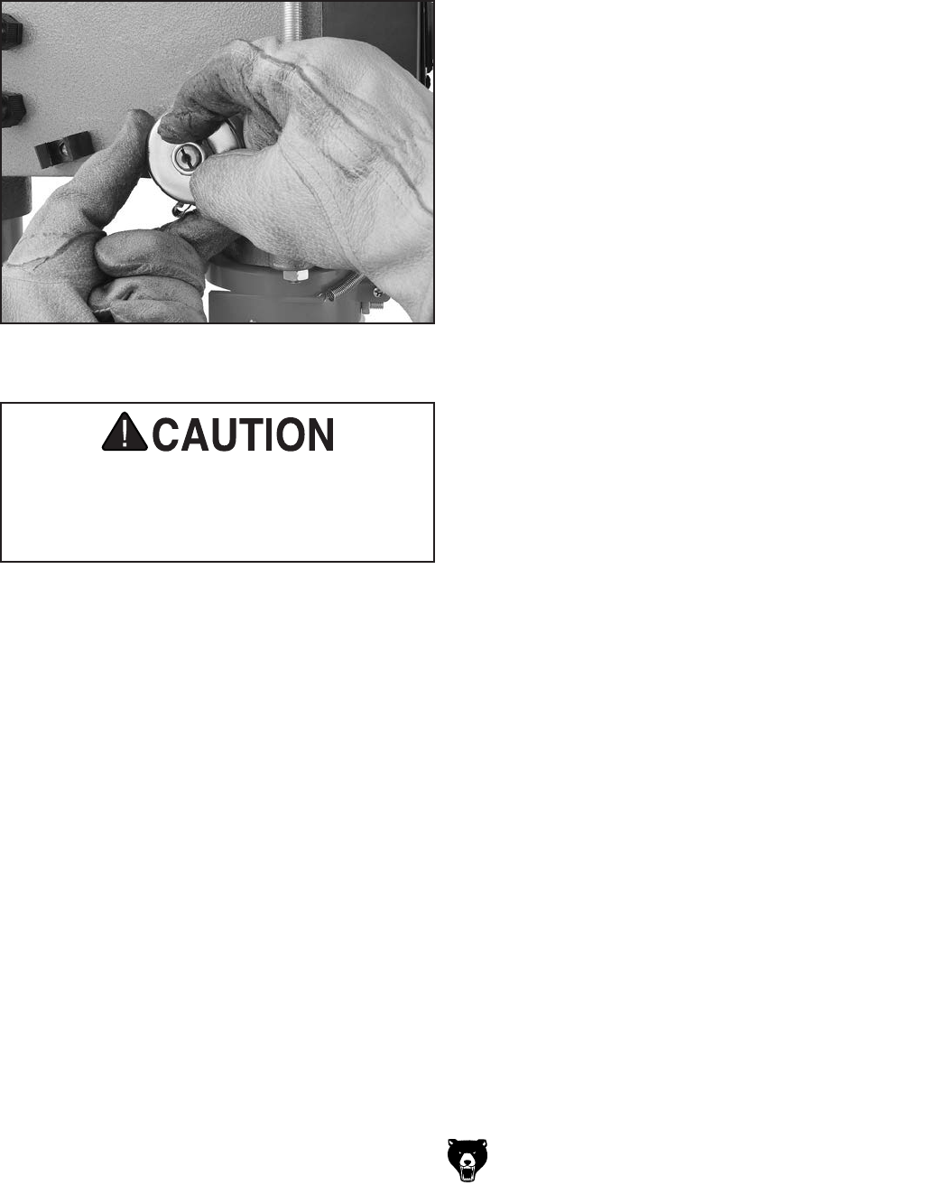
Model G7943/G7944 (Mfg. 10/02+) -39-
Figure 48. Example of loosening cover and jam
nut.
3. While holding the spring lock cover against
the side of the headstock so the cover stays
splined with the locking lug; loosen the jam
nut and loosen the cover nut approximately
1⁄4" (see Figure 48).
4. Put on heavy leather gloves to protect your
hands from possible lacerations if the spring
uncoils during the next step.
5. Pull the cover outward just enough to
disengage the spring-cover lock slot from the
locking lug. Note: It is important to keep a
good grip during this step. Letting go of the
cover will cause the spring to rapidly uncoil.
6. Rotate the cover counterclockwise to increase
spring tension, or let the cover slowly unwind
in the clockwise direction to reduce spring
tension.
7. Engage the next available spring-cover lock
slot with the locking lug and hold the spring
lock cover tightly against the side of the
headstock.
8. Snug the cover nut against the spring cover
just until the nut stops, and then back off
the nut approximately 1⁄3 turn, or just enough
so there is no binding at complete spindle
travel.
9. Hold the cover nut and tighten the jam nut
against the cover nut.
A high tension coiled spring is underneath
the cover. Put on heavy leather gloves to
protect yours hands from possible lacera-
tions when removing the cover.

-40- Model G7943/G7944 (Mfg. 10/02+)
These pages are current at the time of printing. However, in the spirit of improvement, we may make chang-
es to the electrical systems of future machines. Study this section carefully. If there are differences between
your machine and what is shown in this section, call Technical Support at (570) 546-9663 for assistance
BEFORE making any changes to the wiring on your machine.
SECTION 8: WIRING
Wiring Safety Instructions
1. SHOCK HAZARD. Working on wiring that
is connected to a power source is extremely
dangerous. Touching electrified parts will
result in personal injury including but not lim-
ited to severe burns, electrocution, or death.
Disconnect the power from the machine
before servicing electrical components!
2. QUALIFIED ELECTRICIAN. Due to the
inherent hazards of electricity, only a quali-
fied electrician should perform wiring tasks
on this machine. If you are not a quali-
fied electrician, get help from one before
attempting any kind of wiring job.
3. WIRE CONNECTIONS. All connections
must be tight to prevent wires from loosen-
ing during machine operation. Double-check
all wires disconnected or connected during
any wiring task to ensure tight connections.
4. WIRE/COMPONENT DAMAGE. Damaged
wires or components increase the risk of
serious personal injury, fire, or machine
damage. If you notice that any wires or
components are damaged while performing
a wiring task, replace those wires or compo-
nents before completing the task.
5. MODIFICATIONS. Using aftermarket parts or
modifying the wiring beyond what is shown
in the diagram may lead to unpredictable
results, including serious injury or fire.
6. MOTOR WIRING. The motor wiring shown
in these diagrams is current at the time of
printing, but it may not match your machine.
Always use the wiring diagram inside the
motor junction box.
7. CAPACITORS. Some capacitors store an
electrical charge for up to five minutes after
being disconnected from the power source.
To avoid being shocked, wait at least this
long before working on capacitors.
8. CIRCUIT REQUIREMENTS. You MUST fol-
low the requirements on Page 12 when con-
necting your machine to a power source.
9. EXPERIENCING DIFFICULTIES. If you are
experiencing difficulties understanding the
information included in this section, contact
our Technical Support at (570) 546-9663.
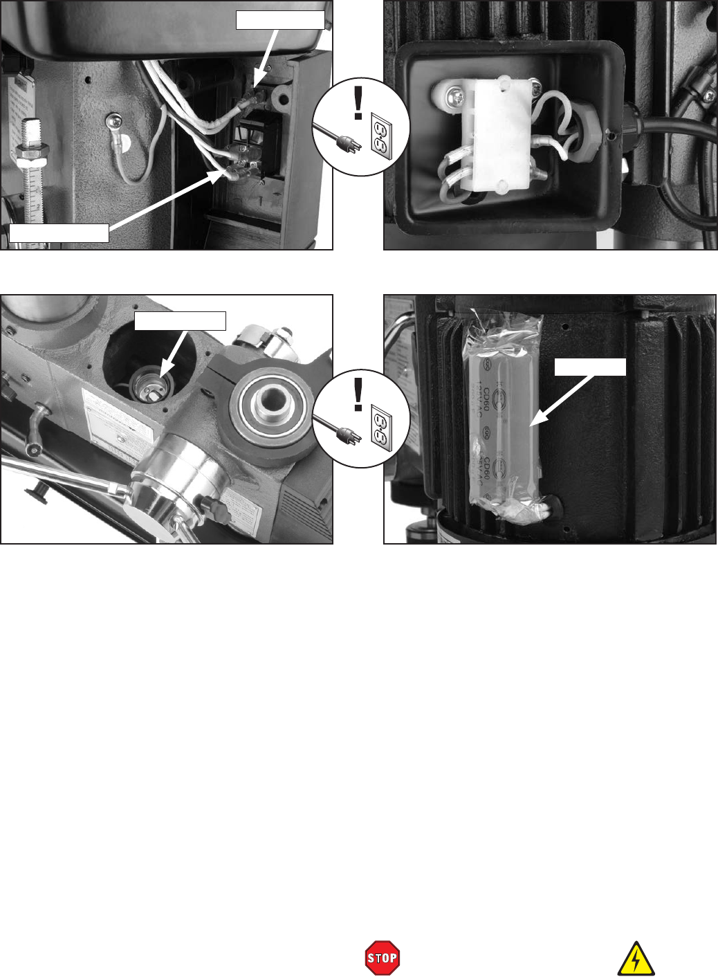
Model G7943/G7944 (Mfg. 10/02+) - 41-
READ ELECTRICAL SAFETY
ON PAGE 40!
Electrical Components
Figure 50. Light socket with dust plug removed.
Figure 51. Motor wiring inside junction box.
Light Switch
Power Switch
Figure 49. Power and light switch assembly.
Figure 52. Capacitor.
Light Socket
Capacitor
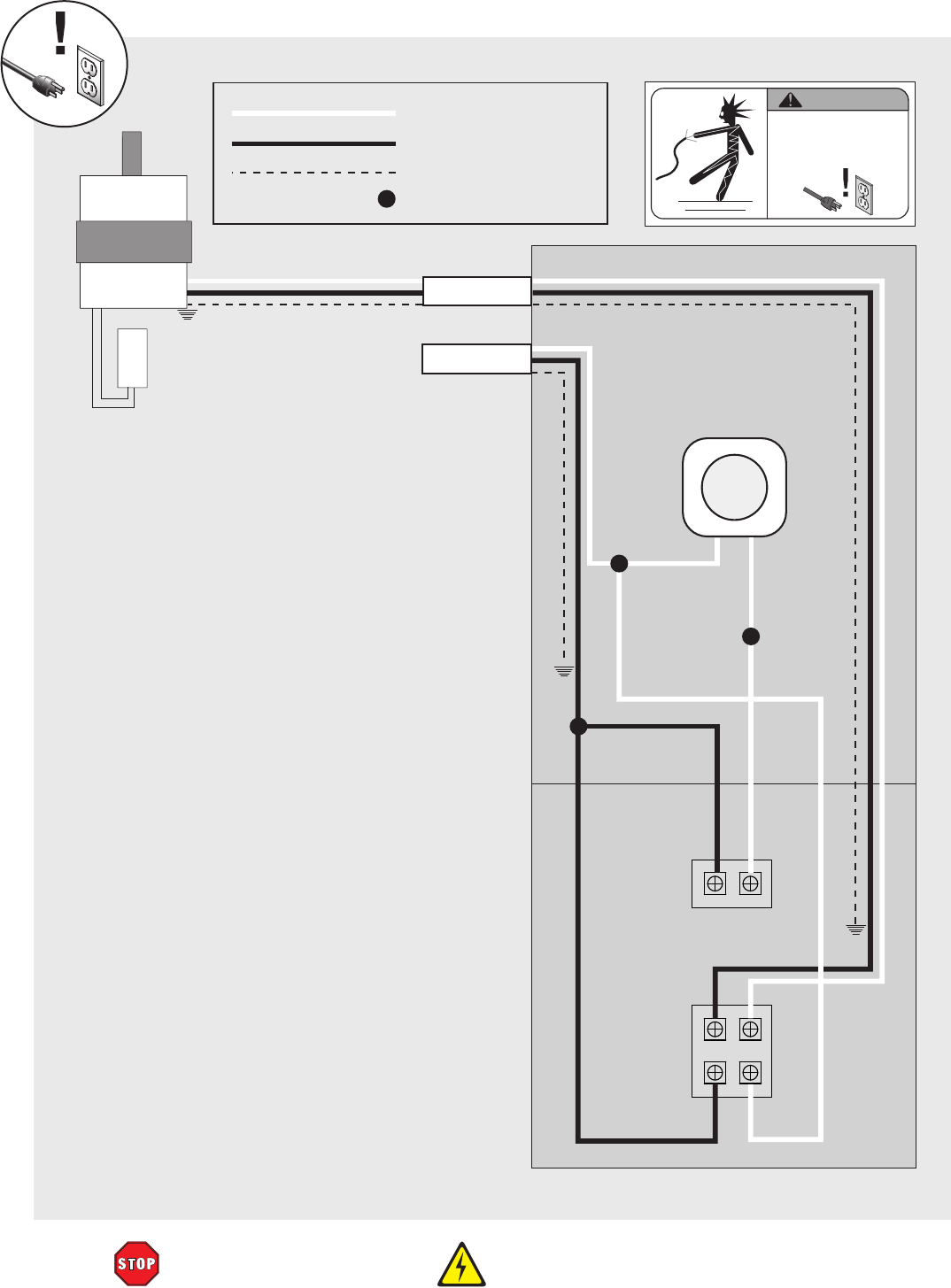
-42- Model G7943/G7944 (Mfg. 10/02+)
READ ELECTRICAL SAFETY
ON PAGE 40!
Light Socket
Light
Switch
Power
Switch
Motor
Capacitor
White
Black
Green (Ground)
Wire Nut Connection
To Power
To Motor
KEY WARNING!
SHOCK HAZARD!
Disconnect power
before working on
wiring.
110V Only
G7943/G7944 Wiring Diagram
Wiring Diagram
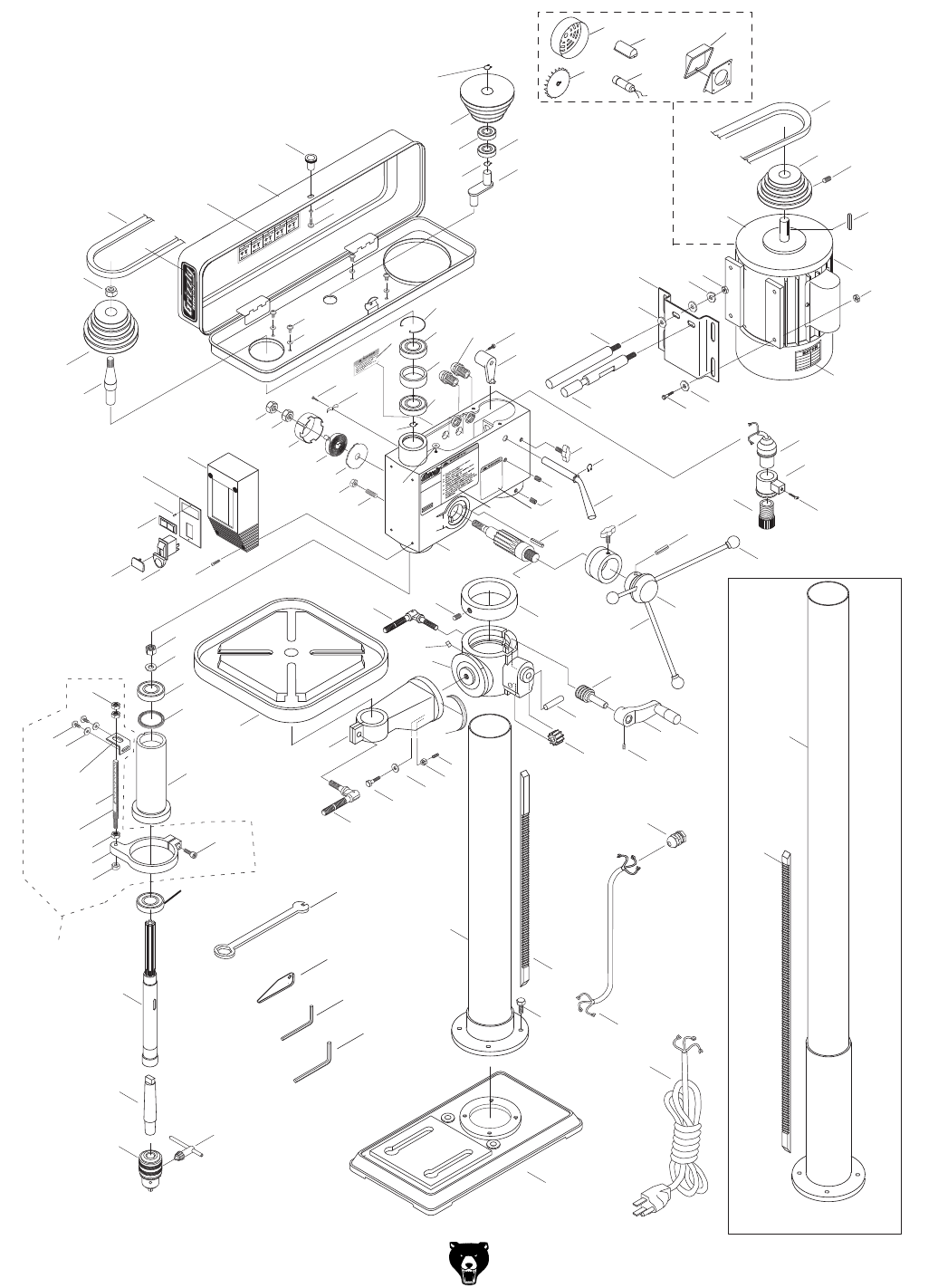
Model G7943/G7944 (Mfg. 10/02+) -43-
G7943/G7944 Breakdown
SPECIFICATIONS
MODEL G7943
DRILL PRESS
B
O
B
A
S
B
E
A
R
I
N
G
C
O
6
2
0
5
-
2
R
S
B
O
B
A
S
B
E
A
R
I
N
G
C
O
6
2
0
5
-
2
R
S
B
O
B
A
S
B
E
A
R
I
N
G
C
O
6
2
0
5
-
2
R
S
110
58-4
58-3 58-1
58-6
58-2
58-5
118
114
68
23A-4
23A
23A-2
23A-3
40
23A-1
37 88
89
90
91 92
101
102
103
4
115
9
10
11
12
13
14
46
40
41
42 43
44
38 39
45
47
96
97
98
98B
83
84
85
86
15
87
40
3A
4A
2
3
6
120
7
8
17
100B
100C
20
22
5
16
18
19
21 23
24
25
26
27
30 33
50
93
94
94A
95
104
105
78
79
81
82
68B 29
32
34
48 49
51
52
53
55
56
56A 57 58
68
69
73
80
35 36
54
63
64
65
66
67
99
72
106
74
75
76
77
37
59
60
61
62
70
71
107
1
117 116
100
G7944 ONLY
119
113

-44- Model G7943/G7944 (Mfg. 10/02+)
REF PART # DESCRIPTION REF PART # DESCRIPTION
1 P7943001 BASE V2.07.04 25 P7943025 HANDLE BODY
2 P7943002 HEX BOLT M10-1.5 x 25 26 P7943026 HANDLE
3 P7943003 RACK 27 P7943027 KNOB
4 P7943004 COLUMN W/ COLUMN SHOULDER 28 P7943028 COLUMN W/ COLUMN SHOULDER
5 P7943005 TABLE BRACKET 29 P7943029 SLIDE BAR BOLT M8 X 20
6 P7943006 HANDLE 30 P7943030 SET SCREW M5-.8 X 10
7 P7943007 SET SCREW M3-1 X 5 32 P7943032 EXT RETAINING RING 15MM
8 P7943008 SHAFT 33 P7943033 SHIFTER BAR
9 P7943009 TABLE PIN 34 P7943034 SLIDE BAR BOLT M10 X 40
10 P7943010 HEX NUT M6-1 35 P7943035 HEX BOLT M8-1.25 X 24
11 P7943011 FLAT WASHER #6 36 P7943036 FLAT WASHER #8
12 P7943012 HEX BOLT M16-2 X 40 37 P7943037 HEX NUT M8-1.25
13 P7943013 TABLE BOLT M10 X 30 38 P7943038 HEX NUT M10-1.25
14 P7943014 TABLE ARM BRACKET 39 P7943039 SPECIAL SET SCREW M10 x 25
15 P7943015 TABLE 40 P7943040 HEX NUT M12-1.5 THIN
16 P7943016 CLAMP BOLT M12 41 P7943041 HEX NUT M12-1.5 THIN
17 P7943017 GEAR 42 P7943042 SPRING CAP
18 P7943018 WORM GEAR 43 P7943043 SPRING-TORSION
19 P7943019 RACK RING 44 P7943044 SPRING COVER
20 P7943020 PIN-STOP 45 P7943045 SWITCH BOX
21 P7943021 SET SCREW M6-1 x 10 46 P7943046 PHLP HD SCR M5-.8 X 12
22 P7943022 FEED SHAFT 47 P7943047 SCREW 4.2 X 9
23 P7943023 DEPTH RING 48 P7943048 PHLP HD SCR M5-.8 X 10
23A-1 P7943023A-1 DEPTH STOP BRACKET V1 49 P7943049 CORD CLAMP
23A-2 P7943023A-2 SCALE V2.11.02 50 P7943050 BODY
23A-3 P7943023A-3 THREADED DEPTH BAR 51 P7943051 HEX BOLT M8-1.25 X 16
23A-4 P7943023A-4 RIGHT ANGLE BRACKET 52 P7943052 SHIFTER
24 P7943024 ROLL PIN 5 X 40
G7943/G7944 Parts List

Model G7943/G7944 (Mfg. 10/02+) -45-
REF PART # DESCRIPTION REF PART # DESCRIPTION
53 P7943053 SLIDE BAR 83 P7943083 ROUND NUT M17-1
54 P7943054 SLIDE BAR 84 P7943084 TAB WASHER
55 P7943055 MOTOR BASE 85 P7943085 BALL BEARING P6203Z
56 P7943056 FLAT WASHER 12MM 86 P7943086 RUBBER WASHER 62 X 50 X 2
56A P7943056A LOCK WASHER 12MM 87 P7943087 SPINDLE SLEEVE
57 P7943057 HEX NUT M12-1.75 88 P7943088 BALL BEARING 6205ZZ
58 P7943058 MOTOR 3/4HP 110V 1PH 89 P7943089 SPINDLE
58-1 P7943058-1 CAPACITOR COVER 90 P7943090 ARBOR
58-2 P7943058-2 CONNECTION BOX 91 P7943091 CHUCK
58-3 P7943058-3 MOTOR COVER 92 P7943092 CHUCK KEY
58-4 P7943058-4 MOTOR FAN 93 P7943093 LIGHT BODY
58-5 P7943058-5 CAST IRON END BELL FOR MOTOR 94 P7943094 LIGHT BASE
58-6 P7943058-6 S CAPACITOR 200MFD 125VAC 94A P7943094A PHLP HD SCR M5-.8 x 20
59 P7943059 MOTOR PULLEY V2.02.99 95 P7943095 LIGHT SCREW (PLUG)
60 P7943060 KEY 5 X 5 X 20 96 P7943096 SWITCH BASE
61 P7943061 SET SCREW M3-1 X 5 97 P7943097 SWITCH (LIGHT)
62 P7943062 V-BELT M24 3L240 98 P7943098 PADDLE SWITCH 110/220V WITH KEY
63 P7943063 CENTER SHAFT 98B P7943098B YELLOW SWITCH KEY
64 P7943064 BALL BEARING 6202ZZ 99 P7943099 INT RETAINING RING 38MM
65 P7943065 BALL BEARING 6202ZZ 100 P7943100 POWER CORD 16-GAUGE 3-WIRE 73"-LENGTH
66 P7943066 EXT RETAINING RING 15MM 100B P7943100B WIRE GASKET
67 P7943067 CENTER PULLEY V2.02.99 100C P7943100C MOTOR CORD
68 P7943068 FLAT WASHER 6MM 101 P7943101 HEX WRENCH 5MM
68B P794368B FLAT WASHER 6MM 102 P7943102 HEX WRENCH 3MM
69 P7943069 PHLP HD SCR M6-1 X 10 103 P7943103 WEDGE SHIFTER
70 P7943070 PHLP HD SCR M5-.8 X 15 104 P7943104 LIGHT WARNING LABEL
71 P7943071 FLAT WASHER #6 105 P7943105 WARNING ID/LABEL
72 P7943072 KNOB 106 P7943106 SPEED CHART LABEL
73 P7943073 PULLEY COVER 107 P7943107 GRIZZLY BLACK/AL LABEL
74 P7943074 V-BELT A25 110 P7943110 TABLE BOLT WRENCH
75 P7943075 PULLEY NUT 113 P7943113 ANGLE SCALE
76 P7943076 SPINDLE PULLEY V2.02.99 114 P7943114 PHLP HD SCR M6-1 X 8
77 P7943077 INSERT PULLEY V2.02.99 115 P7943115 CAP SCREW M8-1.25 X 20
78 P7943078 INT RETAINING RING 62MM 116 P7943116 STRAIN RELIEF
79 P7943079 BALL BEARING 6205ZZ 117 P7943117 DRILL PRESS LABEL
80 P7943080 SPACER 118 P7943118 INDICATOR
81 P7943081 BALL BEARING 6205ZZ 119 P7943119 MOTOR LABEL
82 P7943082 INT RETAINING RING 62MM 120 P7943120 CRANK LEVER
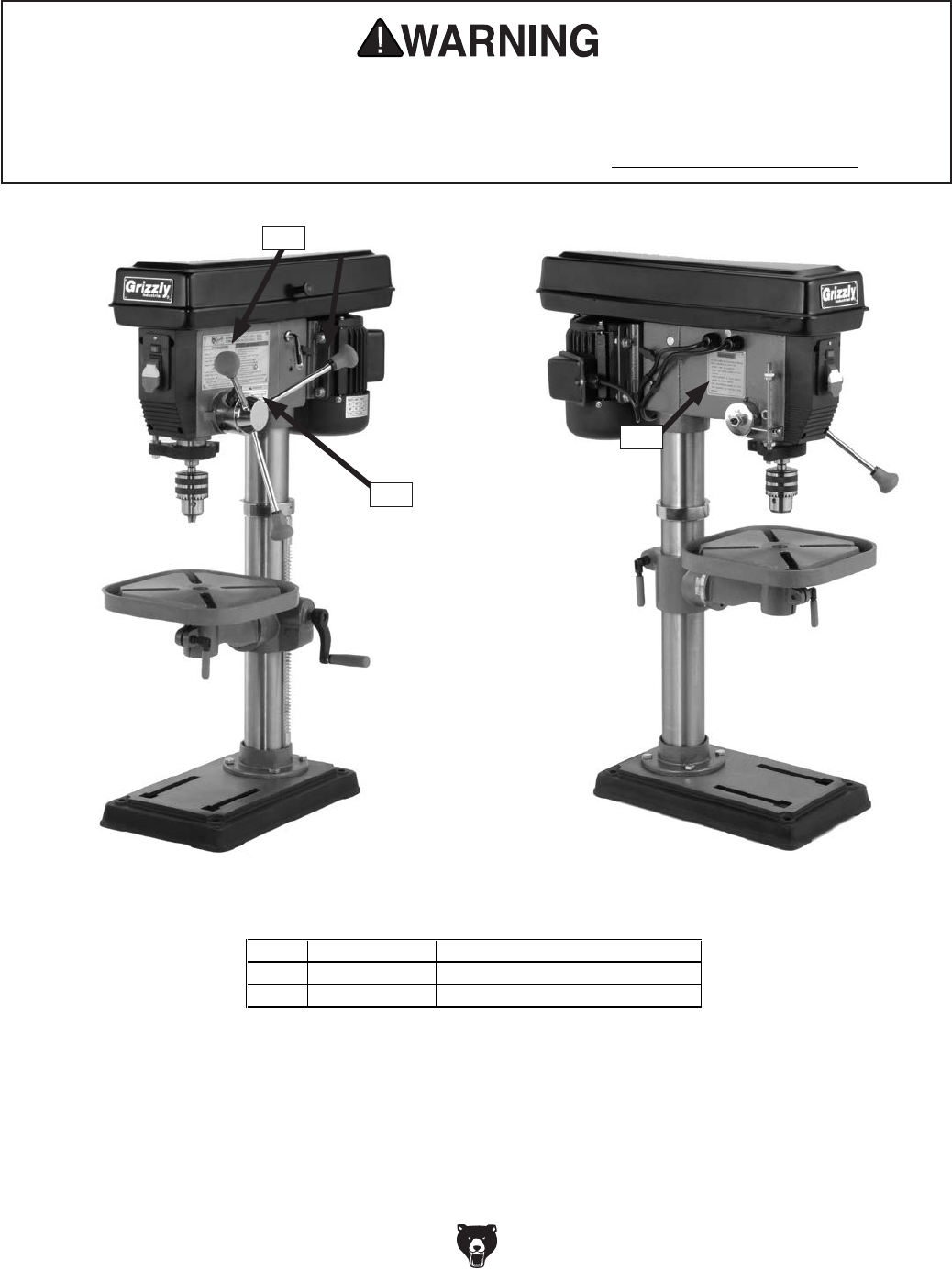
-46- Model G7943/G7944 (Mfg. 10/02+)
Label Placement and Parts List
Safety Label Placement
The safety labels on this machine warn and indicate how to protect the operator or bystander from
machine hazards. The machine owner MUST maintain the original label location and readability.
If a label is removed or becomes unreadable, REPLACE the label before using the machine. For
new labels, contact Grizzly Industrial Inc. at (570) 546-9663 or techsupport@grizzly.com.
REF PART # DESCRIPTION
104 P7943104 LIGHT WARNING LABEL
105 P7943105 WARNING ID/LABEL
117 P7943117 DRILL PRESS LABEL
104
117
105

CUT ALONG DOTTED LINE
Name _____________________________________________________________________________
Street _____________________________________________________________________________
City _______________________ State _________________________ Zip _____________________
Phone # ____________________ Email _________________________________________________
Model # ____________________ Order # _______________________ Serial # __________________
WARRANTY CARD
The following information is given on a voluntary basis. It will be used for marketing purposes to help us develop
better products and services. Of course, all information is strictly confidential.
1. How did you learn about us?
____ Advertisement ____ Friend ____ Catalog
____ Card Deck ____ Website ____ Other:
2. Which of the following magazines do you subscribe to?
3. What is your annual household income?
____ $20,000-$29,000 ____ $30,000-$39,000 ____ $40,000-$49,000
____ $50,000-$59,000 ____ $60,000-$69,000 ____ $70,000+
4. What is your age group?
____ 20-29 ____ 30-39 ____ 40-49
____ 50-59 ____ 60-69 ____ 70+
5. How long have you been a woodworker/metalworker?
____ 0-2 Years ____ 2-8 Years ____ 8-20 Years ____ 20+ Years
6. How many of your machines or tools are Grizzly?
____ 0-2 ____ 3-5 ____ 6-9 ____10+
7. Do you think your machine represents a good value? _____Yes _____No
8. Would you recommend Grizzly Industrial to a friend? _____Yes _____No
9. Would you allow us to use your name as a reference for Grizzly customers in your area?
Note: We never use names more than 3 times. _____Yes _____No
10. Comments: _____________________________________________________________________
_________________________________________________________________________________
_________________________________________________________________________________
_________________________________________________________________________________
____ Cabinetmaker & FDM
____ Family Handyman
____ Hand Loader
____ Handy
____ Home Shop Machinist
____ Journal of Light Cont.
____ Live Steam
____ Model Airplane News
____ Old House Journal
____ Popular Mechanics
____ Popular Science
____ Popular Woodworking
____ Precision Shooter
____ Projects in Metal
____ RC Modeler
____ Rie
____ Shop Notes
____ Shotgun News
____ Today’s Homeowner
____ Wood
____ Wooden Boat
____ Woodshop News
____ Woodsmith
____ Woodwork
____ Woodworker West
____ Woodworker’s Journal
____ Other:

TAPE ALONG EDGES--PLEASE DO NOT STAPLE
FOLD ALONG DOTTED LINE
FOLD ALONG DOTTED LINE
GRIZZLY INDUSTRIAL, INC.
P.O. BOX 2069
BELLINGHAM, WA 98227-2069
Place
Stamp
Here
Name_______________________________
Street_______________________________
City______________State______Zip______
Send a Grizzly Catalog to a friend:

WARRANTY AND RETURNS
Grizzly Industrial, Inc. warrants every product it sells for a period of 1 year to the original purchaser from
the date of purchase. This warranty does not apply to defects due directly or indirectly to misuse, abuse,
negligence, accidents, repairs or alterations or lack of maintenance. This is Grizzly’s sole written warranty
and any and all warranties that may be implied by law, including any merchantability or fitness, for any par-
ticular purpose, are hereby limited to the duration of this written warranty. We do not warrant or represent
that the merchandise complies with the provisions of any law or acts unless the manufacturer so warrants.
In no event shall Grizzly’s liability under this warranty exceed the purchase price paid for the product and
any legal actions brought against Grizzly shall be tried in the State of Washington, County of Whatcom.
We shall in no event be liable for death, injuries to persons or property or for incidental, contingent, special,
or consequential damages arising from the use of our products.
To take advantage of this warranty, contact us by mail or phone and give us all the details. We will then
issue you a “Return Number,’’ which must be clearly posted on the outside as well as the inside of the
carton. We will not accept any item back without this number. Proof of purchase must accompany the
merchandise.
The manufacturers reserve the right to change specifications at any time because they constantly strive to
achieve better quality equipment. We make every effort to ensure that our products meet high quality and
durability standards and we hope you never need to use this warranty.
Please feel free to write or call us if you have any questions about the machine or the manual.
Thank you again for your business and continued support. We hope to serve you again soon.
WARRANTY AND RETURNS

