i Mobile Technology IO-10C Tablet PC User Manual Manual
i-Mobile Technology Corporation Tablet PC Manual
Contents
- 1. Manual
- 2. Addendum
Manual

User’s Manual
IO-10C (2012/12/22)
Copyright
This publication, including all photographs, illustrations and software, is
protected under international copyright laws, with all rights reserved.
Neither this manual, nor any of the material contained herein, may be
reproduced without the express written consent of the manufacturer.
Disclaimer: The manufacturer makes no representations or warranties with
respect to the contents hereof and specifically disclaim any implied warranties
of merchantability or fitness for any particular purpose. The manufacturer is
not liable for technical and editorial error for this guide. The manufacturer
reserves the right to revise or make changes to this publication without notice
or obligation of the manufacturer to notify any person of such revision or
changes.
Software Licenses
The software included with the product and referenced in this document is
furnished under a License Agreement. This Agreement specifies permitted
and prohibited uses of this product.
General Guidelines
Read all of the instructions carefully.
Save the instructions for future use.
To ensure follow all warnings and instructions marked in the product
documentation and within the computer.
Except as explained elsewhere in this manual, do not attempt to service
the computer yourself. Opening or removing covers might expose you to
dangerous voltage points or other risks. Refer all servicing of marked
components to qualified personnel.
Power Cord Requirements
The power cord you received with this computer conforms to local
specifications for use in the country where you purchased it. Power cord use
in other countries may require an additional adapter and/or separate power
cord. For additional information on local power requirements, contact an
authorized dealer, reseller, or service provider.
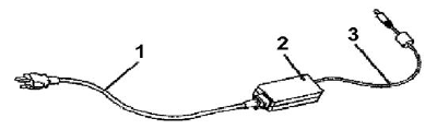
About the AC Adapter
The AC adapter will automatically recognize any compatible power supply
connected to the computer. The AC adapter can also be used to recharge the
battery, which begins immediately after the AC Adapter cord is connected. A
green LED will light to confirm charging is in progress. The ideal range for safe
operation of the computer is from 100 ~ 240V AC.
1. AC Power Cord / 2. AC Adapter / 3. DC (Direct Current) Cord
Warning :
Using the AC adapter to power other devices can damage the adapter or
the device. This AC adapter is only designed for use with the product.
Be sure to only use the AC adapter that comes provided with this product
or a compatible option from the manufacturer. Other adapters may cause
damage to the computer and will not be covered under the warranty.
Grasp the adapter plug and not the cord, when unplugging the adapter
from an electrical outlet.
If the power cord becomes damaged (exposed or frayed, etc.), replace with
a new AC adapter. Using a damaged cord may cause an electrical shock
and may result in fire.
Power off and unplug the AC adapter from the computer before unplugging
it from the electrical outlet.

Battery (Lithium-Ion)
NOTE: Refer to following hazard statement within the service and
operating documentation or on the adjacent label to the
battery.
1. English
CAUTION: DANGER OF EXPLOSION IF BATTERY IS INCORRECTLY
INSTALLED. REPLACE ONLY WITH SAME OR EQUIVALENT TYPE
RECOMMENDED BY THE MANUFACTURER. DISCARD OF USED
BATTERIES IN ACCORDANCE WITH THE MANUFACTURER'S
INSTRUCTIONS.
2. French
IL Y A DANGER D'EXPLOSION S'IL Y A REMPLACEMENT
INCORRECT DE LA BATTERIE. REMPLACER UNIQUEMENT AVEC
UNE BATTERIE DU MÊME TYPE OU D'UN TYPE RECOMMANDÉ
PAR LE CONSTRUCTEUR. METTER AU RÉBUT LES BATTERIES
USAGÉES CONFORMÉMENT AUX INSTRUCTIONS DU
FABRICANT.
3. German
VORSICHT ! Explisionsgefahr bei unsachgemäßen Austausch der
Batterie.
Ersatz nur durch denselben oder einem vom Hersteller empfohlenem
ähnlichen Typ.
Entsorgung gebrauchter Batterien nach Angaben des Herstellers.
4. Swedish
Explosionsfara vid felaktigt batteribyte.
Använd samma batterityp eller en ekvivalent typ som rekommenderas
av apparattillverkaren. Kassera använt batteri enligt fabrikantens
instruktion.
5. Danish
Lithiumbatteri- Eksplosionsfare ved fejlagtig håndtering.
Udskiftning må kum ske med batteri af samme fabrikat og type.
Lever det brugte batteri tilbage til leverandoren.
6. Norwegian
Ekspolsjonsafe ved feilaktig skifte av batteri.
Benytt samme batteritype eller en tilsvarende type anbefalt av
apparatfabriknten.
Brukte batterier kasseres I henhold til fabrikantens instruksjoner.
7. Finnish
Paristo voi räjähtää, jos se on virheellisesti asennettu.
Vaihda paristo ainostaan laitevalmistajan suosittelemaan tyyppiin.
Hävitä käyteet paristo valmistajan ohjeiden mukaisesti.
FCC Statement
This equipment has been tested and found to comply with the limits for a
Class B digital device, pursuant to part 15 of the FCC Rules. These limits are
designed to provide reasonable protection against harmful interference in a
residential installation. This equipment generates, uses, and can radiate radio
frequency energy, and if not installed and used in accordance with the
instructions, may case harmful interference to radio communications.
However, there is no guarantee that interference will not occur in a particular
installation. If this equipment does cause harmful interference to radio or
television reception, which can be determined by turning the equipment off
and on, the user is encouraged to try to correct the interference by one or
more of the following measures:
Reorient or relocate the receiving antenna.
Increase the separation between the equipment and receiver.
Connect the equipment into an outlet on a circuit different from that to
which to receiver is connected.
Consult the dealer or an experienced radio/TV technician for help.
Use of shielded cord is required to comply with Class B limits in Subpart B of
Part 15 of the FCC rules. Do not make any changes or modifications to the
equipment unless otherwise specified in the manual. If such changes or
modifications should be made, you could be required to stop operation of the
equipment.
FCC Caution:
1. The device complies with Part 15 of the FCC rules. Operation is subject to
the following two conditions
1 This device may not cause harmful interference.
2 This device must accept any interference received, including
interference that may cause undesired operation.
2. This Transmitter must not be co-located or operating in conjunction with
any other antenna or transmitter.
3. FCC RF Radiation Exposure Statement
This device has been tested for compliance with FCC RF Exposure (SAR)
limits. The equipment complies with FCC RF radiation exposure limits set
forth for an uncontrolled environment.
4. Changes or modifications to this unit not expressly approved by the party
responsible for compliance could void the user authority to operate the
equipment.
CE Statement
This equipment has been designed to comply with EMC directive 89/336/EEC
As a amended by 92/31/EEC and the Low Voltage directive 2006/95/EC,
Manufacturers will need to test and approve the product to these directives.

Table of Contents
BEFORE USING YOUR COMPUTER .................................................. 1
Product Features .......................................................................... 2
Installation Guidelines ................................................................... 4
CHAPTER 1 ............................................................................... 6
GETTING STARTED ....................................................................... 6
Unpacking the Product .................................................................. 7
Packing List .................................................................................. 7
Power Supply ............................................................................... 8
Using the Battery ...................................................................................... 8
To install and remove the Battery Pack.................................................... 8
Installing the Battery/ Remove / Replacing the Battery ........................... 9
Caring for the Battery……………………………………………………….11
Using the AC adapter ............................................................................. 11
The Stylus Pen ........................................................................... 13
Performing Mouse Clicks and Other Procedures with the Stylus Pen .. 13
For Optimal Performance from the Stylus Pen ...................................... 14
The CMOS Camera .................................................................... 14
CHAPTER 2 ............................................................................. 15
SYSTEM OVERVIEW .................................................................... 15
Front View of the Computer......................................................... 16
Right Side View of the Computer ................................................. 21
Left Side View of the Computer ................................................... 22
Top View of the Computer ........................................................... 23
Bottom View of the Computer ...................................................... 23
Rear View of the Computer ......................................................... 24
CHAPTER 3 ............................................................................. 26
PROTECTING AND MAINTAINING ................................................... 26
Caring for Your Computer............................................................ 27
Routine Care ........................................................................................... 27

Caring for the Battery ............................................................................. 27
Caring for the AC Adapter ...................................................................... 28
Caring for the Touch Screen Display ..................................................... 28
The System BIOS Utility .............................................................. 29
Adjusting the Video Resolution .................................................... 30
Changing the Video Resolution of the Computer .................................. 30
CHAPTER 4 ............................................................................. 31
SPECIFICATIONS & SOFTWARE ..................................................... 31
Specifications and Standard Features ......................................... 32
Software ..................................................................................... 35
Using the Smart Panel to Calibrate the Screen ..................................... 35
Using The Front Panel Hot Key Utility ................................................... 36
Define the function for Hot Key Utility .................................................... 38
Using the Bluetooth Utility, BlueSoleilTM ................................................. 39
Making a 3.5G Connection and Disconnection ..................................... 41
Using the CMOS Camera ....................................................................... 42
Using The RFID ...................................................................................... 43
Using the Minismart card ....................................................................... 44
Using the Barcode Scanner ................................................................... 45
Using the MSR ........................................................................................ 47
Using the GPS ........................................................................................ 47
Using the Brightness Adjust ................................................................... 49
Trouble Shooting..................................................................................... 50
B
Be
ef
fo
or
re
e
U
Us
si
in
ng
g
Y
Yo
ou
ur
r
C
Co
om
mp
pu
ut
te
er
r
Congratulations on your purchase of the product.
You will soon be in command of the worlds most lightweight,
efficient and secure solution for managing all of your
technology and mission critical data. Scale the computer and
streamline the costs of day-to-day business operations and
multimedia demands. Discover the computer’s unparalleled
in-the-field versatility for efficiently and reliably coordinating a
myriad of tasks without costing a fortune.
Chapter Preview:
Product Features
Installation Guidelines

The Instructions Manual
2
Product Features
The product is a portable multimedia device empowering highly mobile users
with wireless computing capabilities for day-to-day business and wireless
applications. Its light weight and supreme portability combined with
state-of-the-art multimedia capabilities provide exceptional writing,
maneuvering, and on your feet computing. The product’s primary features
include:
Processor and OS (Operating System): INTEL AtomProcessor Dual
Core N2600 1.6 GHz and Microsoft® Windows 7 Professional / Embedded
and Linux OS, a stable platform, providing exceptional performance for
highly mobile users under extreme and variable conditions.
Multimedia LCD Display: 10.1-inch TFT (1024x600) LCD with Touch
Screen Control Panel (LED back light / Sunlight readable) and Smart Panel
Application enhancing user’s ability to view data outdoors and under
moving conditions.
Complete Connectivity from Anywhere: The computer’s built-in
Bluetooth 3.0®, IEEE 802.11b+g+n WLAN and 3.5G Module offers the
mobile user the maximum opportunities to stay connected from anywhere,
ensuring uninterrupted data sharing and synchronization. Limitless instant
accesses to business critical information.
Integrated Ports and Adaptability: Multiple I/O ports (2 x USB 2.0,
RS-232 Port) provide optimum versatility for any industrial or Business
needs. Its ultra light weight and integrated wireless capability enable an
effective mobile office. Multiple carrying options provide quick on-the-fly
versatility while executing daily tasks comfortably and efficiently.
Before Using Your Computer
3
Special Integrated Functions: Multiple special devices, RFIDBar Code
ScannerMSRSmart Card Reader 2M / 5M Pixel both sides Camera,
can provide useful functions for business and industrial area.
Enhanced Protective Equipments The computer, designed for IP65
ingress protection rating, can provide indoor and outdoor protections of no
ingress of dust and water jets against enclosure without harmful effects.
Furthermore, the computer is equipped with 4 corner buffers to avoid
drop-shock damages.
Note: Read the following Instructions Manual carefully before unpacking
and setting it up. Refer to the Instructions Manual if you encounter any
problems. Keep this Instructions Manual on hand for your reference.

The Instructions Manual
4
Installation Guidelines
Read the following before assembling or disassembling the computer:
1. Follow all warnings and instructions marked on the product and within the
Manual.
2. Before you begin cleaning the computer, make sure that you have
unplugged all power cords and the device is Powered Off. Use a damp
cloth for cleaning. Do not use liquids of any kind of aerosol cleaners.
3. Never place the computer on an unstable surface; it may fall, causing
serious damage to it.
4. Avoid using a telephone (other than a cordless type) with the computer
during an electrical storm. There may be remote risk of electric shock from
lightning.
5. To ensure optimum performance and to protect the computer from
overheating, ventilation slots must not be covered or obstructed in any way.
The computer should never be placed near a radiator, heat register or in a
built-in cabinet unless adequate ventilation is provided.
6. The computer should only be operated using the specified power indicated
on the Warning Label located on the battery. If you are unsure of the type of
power available to your locale, consult a dealer or the local power
company.
7. If using an extension cord with the computer, make sure that the total
ampere rating of the equipment plugged into the extension cord does not
exceed the extension cord ampere rating. Also note that the total rating of
all the devices plugged into the circuit does not exceed the fuse rating.
8. Never force objects of any kind into the computer’s ventilation or housing
slots as they may contact dangerous voltage points or spark resulting in
electrical shock or a fire. Keep all liquids of any kind away from the
computer.
9. Always disconnect all telephone lines & all power cords from the wall outlet
before servicing or disassembling this product. Refer to the dealer or a
qualified technician under the following conditions:
Before Using Your Computer
5
a. When the power cord or plug is damaged or frayed.
b. If liquid has been spilled into the product.
c. If the computer has been exposed to rain or water.
d. If the computer does not operate normally when the operating
instructions are followed. Adjust only those controls that are specified in
the Operating Instructions or improper adjustment may require
calibration again from a qualified technician.
e. If the computer has been dropped or the housing has been damaged.
f. If the computer experiences a distinct change in performance, indicating
a need for service.

C
C
H
H
A
A
P
P
T
T
E
E
R
R
1
1
G
G
e
e
t
t
t
t
i
i
n
n
g
g
S
S
t
t
a
a
r
r
t
t
e
e
d
d
Chapter Preview:
Unpacking and setting up the Product
Packing list
Power Supply
The Stylus Pen
The CMOS Camera
CHAPTER 1 - Getting Started
7
Unpacking the Product
Before unpacking the product, prepare a suitable workspace for your
computer. Make sure the workspace is level, stable and near an electrical
outlet.
1. Open the box and remove the contents preserving the integrity of the box
as you may need it and all of the packing materials for future shipping.
2. Inspect the contents for damage. If you find any irregularities or anything
appears to be missing, contact your Dealer immediately. Check that the
following components are included in the box:
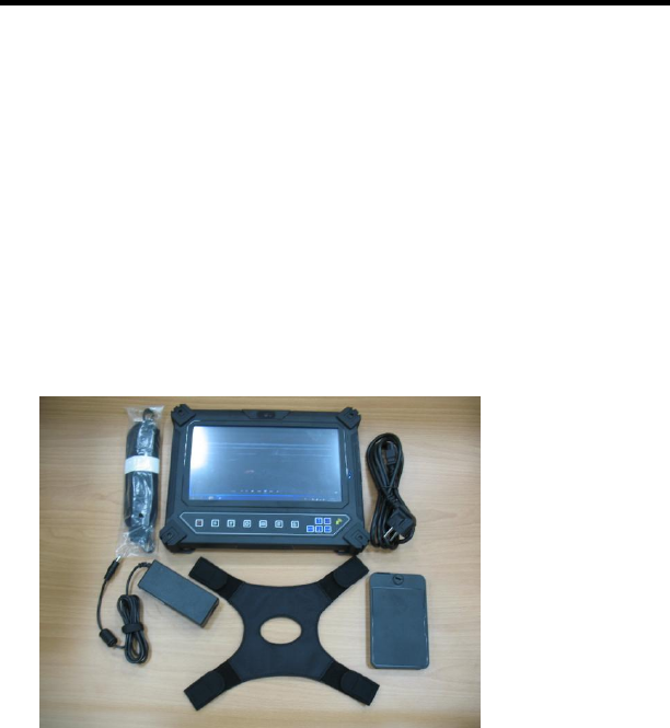
Packing List
1. The Computer Unit 4. Hand Strip
2. Belt 5. Power Cord
3. AC Power Adapter 6. Battery
1
2
3
4
5
6

The Instructions Manual
8
Power Supply
The computer can be powered using either the built in battery or the AC
Power Adapter plugged into any grounded AC power outlet.
Using the Battery
The primary source of power for the computer is a Lithium-Ion battery pack.
The battery pack will first need to be installed on the backside of the computer.
After following the battery installation instructions below, plug the AC adapter
into any electrical outlet and the computer will begin recharging immediately.
In the future, you should not have to access the battery pack unless you wish
to replace it with a fresh one.
Note:
1. The Battery LED lights green when charging and will turn off when the
battery is fully charged.
2. When charging the first time, it is recommended that the battery be
allowed to charge for no less than eight hours.
3. It will take a longer time to complete the charging process, if the user is
using the computer at the same time.
To install and remove the battery pack:
Using the Power Switch to power down the computer.
CHAPTER 1 - Getting Started
9
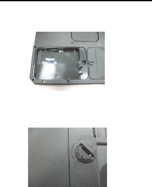
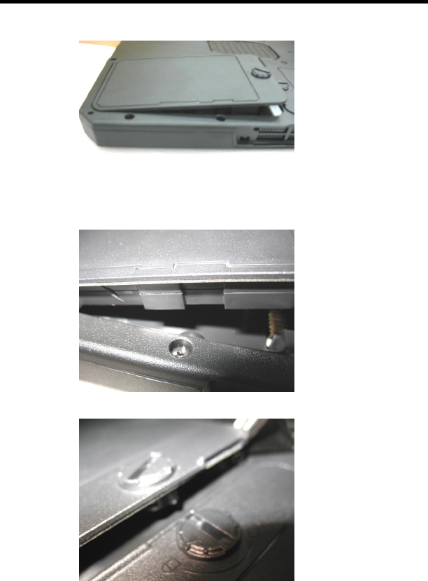
Installing the Battery / Removing/Replacing the Battery:
1. Turn the twist-lock knob to Unlock position and gently put the batteries
into the battery bay. Then, turn the twist-lock knob to Lock position.
The Instructions Manual
10
CHAPTER 1 - Getting Started
11
2. Turn the twist-lock knob to Unlock position and gently take out the
batteries. Carefully lift the batteries out.
Caring for the Battery
Do not heat, tamper or place the battery in water or near a fire.
Do not subject the battery to unusual forces such as hitting it, stepping on it
or dropping it.
Do not attempt to open or service the battery pack.
Only replace the battery with the same model or one of compatible design.
Using the AC Adapter
When connecting the computer to external power:
1. Plug the DC power cord into the DC jack on the computer.
2. Plug the 3-prong AC power adapter cord into a grounded electrical outlet.
Use the AC adapter to power the computer or recharge the battery when it is
low.

The Instructions Manual
12
Caring for the AC Adapter
Be sure to only use the AC adapter that comes provided with this product
or a compatible option from the manufacturer. Other adapters may cause
damage to the computer and will not be covered under the warranty.
Grasp the adapter plug and not the cord, when unplugging the adapter
from an electrical outlet.
If the power cord becomes damaged (exposed or frayed, etc.), replace with
a new AC adapter. Using a damaged cord may cause an electrical shock
and may result in fire.
Power off and unplug the AC adapter from the computer before unplugging
it from the electrical outlet.

CHAPTER 1 - Getting Started
13
The Stylus Pen
The stylus pen emulates all of the functions of a standard mouse and can be
effortlessly used in place of a mouse and a standard keyboard. The stylus pen
tucks into a designated holder on the lower left side of the computer.
Performing Mouse Clicks and Other Procedures with the Stylus Pen
To select an item or open a menu on the screen as you usually left click on an
external mouse:
Tap the item or menu with the tip of the stylus pen
To double-click an item on the screen as you normally double click an external
mouse:
Tap the item twice with the tip of the stylus pen. (You need to lift the stylus
pen from the screen quickly between taps.)
To select an item as you normally right click on an external mouse:
Press the tip of the stylus pen on the item and hold it until the pop-up
menu appears, then tap the choice.
You can also use the stylus pen to write characters, symbols and draw
pictures using additional handwriting software, for example, Windows XP
Painter.
The five basic stylus pen operations and their external mouse equivalents can
be quickly referenced in the table below:
Stylus Pen External Mouse
Point Point
Tap Click
Double-tap Double-click
Tap and hold Right-click
Drag Drag

The Instructions Manual
14
For Optimal Performance from the Stylus Pen
Hold the stylus pen in the same way that you would hold a pen or pencil
when writing on paper.
Hold the computer securely when mobile and using the stylus pen.
Lift and tap the stylus pen quickly between double taps. Avoid using the
stylus pen to push the computer buttons.
For the most reliable operations, hold the stylus pen and tap vertically,
perpendicular to the LCD display.
The CMOS Camera
This computer offers two CMOS Cameras. The user can take a picture
forward and backward.
The Brightness Adjustment
On MCU-base programmable controller with capacitance sensors, the user
can adjust the screen brightness with fingers directly.
C
C
H
H
A
A
P
P
T
T
E
E
R
R
2
2
S
S
y
y
s
s
t
t
e
e
m
m
O
O
v
v
e
e
r
r
v
v
i
i
e
e
w
w
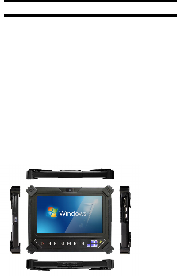
This chapter contains six illustrations, highlighting each
external component and its respective functions.
Chapter Preview:
Front view of the Computer
Right side view of the Computer
Left side view of the Computer
Top view of the Computer
Bottom view of the Computer
Rear view and Build In Back Stand
The Instructions Manual
16
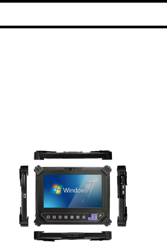
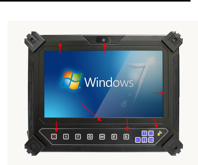
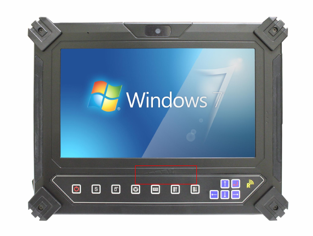
Front View of the Computer
1. 10.1 inch TFT (1024x600) LCD Display with Touch Screen Control
Panel:
Data can be entered the computer module using the stylus pen or a
soft/USB/wireless keyboard. A soft keyboard can be located by tapping
the keyboard icon in the bottom right on the desktop. Data can also be
entered via a USB keyboard plugged into the USB port on the right side of
the computer. The computer’s USB ports support most USB keyboards
and pointing devices.
1. 10.1” TFT LCD
Display
2. Indicator
4. Front Panel
5. Brightness
Adjust
6. Power
Button
7. Micro Phone 8. Front CMOS Camera
3. RFID
CHAPTER 2 – System Overview
17
2. Status LEDs:
LED Indicator
Relevant
Component
Description
Orange (Flashing) Hard Drive Disk Accessing
Green (Off) Battery Battery Available
Green (Solid) Battery Battery Charging
Blue (Solid) Power System Powered On
3. RFID Device :
The HF RFID Reader device is a communication device which includes
complete circuits to achieve reading from and writing to the RFID tag. It
conforms to various industry standard RF protocols of NFC.
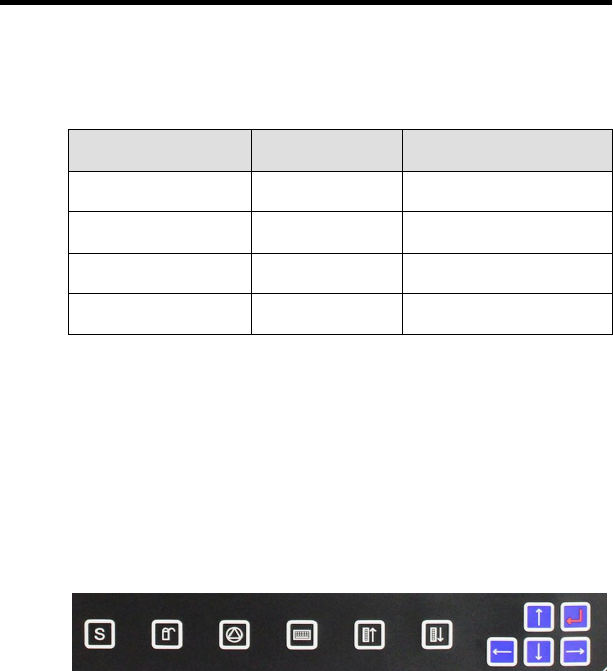
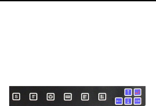
4. Front Panel Buttons:
The above 11 quick access buttons are used for navigating applications
in the Microsoft Windows 7 environment (or relevant OS) and to setup the
System BIOS Utility in DOS mode (alternative function).
1
2
3
4
5
6
7
11
10
9
8

The Instructions Manual
18
The Quick Reference table below illustrates the Button, its
alternative Function, and a brief Function Description while in the
System BIOS Utility in DOS Mode
Button
Keyboard Function
Description in Bios Utility
1 F2 Launch CMOS Setup Utility
2 F9 Load default configuration
3 F10 Save and Exit
4 + Change Value
5 - Change Value
6 <Esc> Exit / Return
7 <> Move / Select Item
8 <> Move / Select Item
9 <Enter> Selection Confirmation
10 <> Move / Select Item
11 <> Move / Select Item
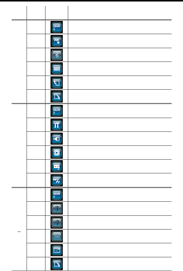
Navigating applications in Microsoft® Windows® 7 Environments
Use the quick reference table below to identify each button’s default setting.
Users can define each quick access button by invoking the Key Define
Utility (Hot Key definition section). The quick launch icon appears in the
Windows systems tray, in the lower-right corner of the Windows desktop.
CHAPTER 2 – System Overview
19
Level
Button
Label
Brief Description of Function
1
1
Rotate Key to Next Level
2
Enable / Disable Touch Screen Function
3
Enables/Disables Blue Tooth Function
4
Invokes On-Screen Keyboard
5
S
Sc
cr
ro
ol
ll
l
P
Pg
gU
Up
p
6
S
Sc
cr
ro
ol
ll
l
P
Pg
g
D
Do
ow
wn
n
2
1
Rotate Key to Next Level
2
Warm Start: <Ctrl><Alt><Delete>
3
I
In
nv
vo
ok
ke
es
s
V
Vo
ol
lu
um
me
e
C
Co
on
nt
tr
ro
ol
l
U
Ut
ti
il
li
it
ty
y
4
Invokes Window Media Player
5
Voice Recording Start/Stop
6
Enables/Disables Wireless Function
3
1
Rotate Key to Next Level
2
Enables/Disables Barcode Scanner
3
Barcode Scanner Trigger
4
Enables/Disables 3G Function
5
Screen Resolution
1024x768 1024x600
6
Screen Rotation

The Instructions Manual
20
Level
Button
Label Brief Description of Function
All
Levels
7 <> Define By User or (Need the Key Code)
8 <> Down Arrow
9 <Enter> Enter
10 <> Up Arrow
11 <> D
De
ef
fi
in
ne
e
B
By
y
U
Us
se
er
r
o
or
r
(
(N
Ne
ee
ed
d
t
th
he
e
K
Ke
ey
y
C
Co
od
de
e)
)
5. Brightness Adjustment :
The built-in MCU-programmable capacitor sensor supports a useful and
handy operate.
6. Power Button :
Start Pressed the Power Button after 1~2 seconds
Reset Press and hold for 4~5 seconds then release to Re-start the
computer
Power OFF Press and hold for 8~10 seconds to Power off the
computer
7. Internal Microphone:
Effortless input of monaural sound recording.
8. The Front CMOS Camera :
The build-in front CMOS Camera supports video applications for all
media software. The user can make a video communication in the
network.
CHAPTER 2 – System Overview
21
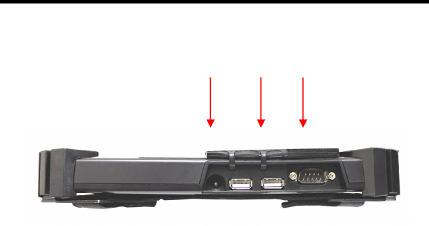
Right Side View of the Computer
9 . DC-in Jack:
Plug the DC (Direct Current) end of the AC Adapter into this jack for
external power and battery recharging. Before plugging in the power cord,
you must first verify that the external power voltage is appropriate for your
geographical area.
10. USB 2.0 Ports:
Permits hot plugging of USB peripheral devices to the computer. The
USB ports support most USB mouse and keyboard devices.
11. RS-232 Port:
Offer an interface connecter of RS-232 that extended application of
instruments for industrial use.
9. DC-In 10. USB 11. RS-232
The Instructions Manual
22
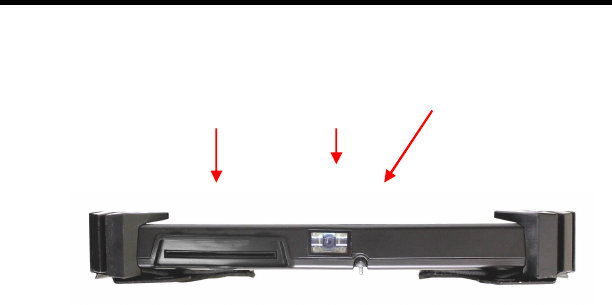
Left Side View of the Computer
12. Stylus Pen:
A stylus pen is used to activate the touch screen display and functions in
the same way as an external mouse. The stylus pen is partially visible
from the left side of the computer and can be located by pulling it from its
secure housing. Only use the tip of the stylus pen when interacting with
the LCD display to prevent damage to the display surface.
13. Barcode Scanner: (optional)
Omni directional bar code reading.
Scan rate of up to 200 scans per second in linear emulation mode or 56
scans per second in Omni directional mode.
Fully compatible with Intermec’s family of decoded engines.
14. Mini Smart Card Reader: (optional)
This device can read a various data include ATM card for business.
14. Mini Smartcard
reader 13. Barcode
Scanner 12. Style Pen
CHAPTER 2 – System Overview
23
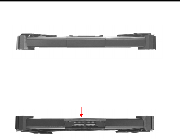
Top View of the Computer
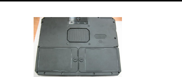
Bottom View of the Computer
15. Docking Slot
The extended multi-function included: the battery charger port, the USB
ports supporting most USB mouse and keyboard devices, RJ-45 Internet
port, RS-232 port, DC-In Jack, Microphone and Headphone.
15. Docking Slot
The Instructions Manual
24
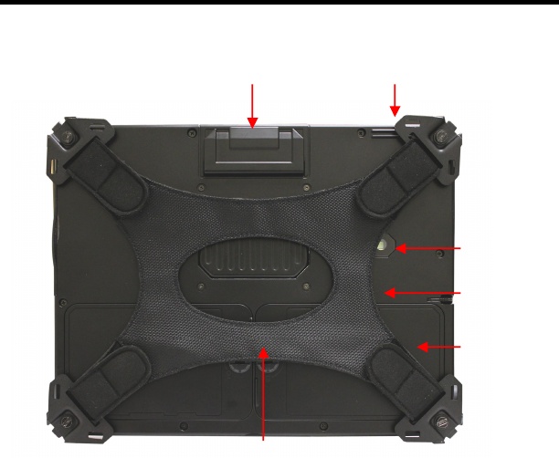
Rear View of the Computer
16. MSR: (optional)
The reader delivers superior reading performance with the ability to
encrypt sensitive card data.
17. GPS: (optional)
Support 50-channel GP
18. Rear CMOS Camera: (optional)
The build-in 5M pixels CMOS camera module supports auto reverse
function. Images can be captured and disseminated instantaneously.
16. MSR
18. Rear
CMOS
Camera
20 . Battery
Pack
17. GPS
21 . Hand Strip
19 . Speaker

CHAPTER 2 – System Overview
25
19. Internal Speakers:
The computer’s built-in a single speaker support audio applications for all
media software. Volume and equalizer control can be adjusted via the OS
or additional multimedia application software. Sound will mute when
headphones are detected.
20. Battery Pack:
A couple 4-cell 3760mAh removable Lithium-Ion battery pack comes
standard with the computer. Each cell comes equipped with short circuit,
over-charge, over-discharge, over-current and abuses protection.
21. Hand Strip:
The user can carry the machine by the Palm.

C
C
H
H
A
A
P
P
T
T
E
E
R
R
3
3
P
P
r
r
o
o
t
t
e
e
c
c
t
t
i
i
n
n
g
g
&
&
M
M
a
a
i
i
n
n
t
t
a
a
i
i
n
n
i
i
n
n
g
g
Chapter Preview:
Caring for your Computer
The System BIOS Utility
Configuring DRAM, HDD and SIM Card
Connecting to a Local Area Network
Adjusting the Resolutions for the Computer’s Display and
an External Display

CHAPTER 3 – Protecting & Maintaining
27
Caring for Your Computer
To guarantee a long life for the computer and to ensure it functions optimally,
pay particular attention to the following recommended maintenance
guidelines.
Routine Care
Follow these guidelines to keep the computer working properly:
Do not attempt to disassemble or modify the computer in any way.
Do not place anything on top of the device or its LCD display to prevent
damage to the screen.
Avoid using and storing the computer in locations where static or electrical
interference can damage in the internal components.
Avoid using and storing the computer in locations exposed to extreme
temperature fluctuations, likely condensation, or direct sunlight.
Keep the device away from moisture such as exposure to liquids or
precipitation.
Only operate the device with the battery pack installed, even when using
external power. This ensures the computer will have the sufficient power to
maintain and save data when disconnected from the external power
source.
Store the device in its docking station when not in use.
Caring for the Battery
Do not heat, tamper or place the battery in water or near a fire.
Do not subject the battery to unusual forces such as hitting it, stepping on it
or dropping it.
Do not attempt to open or service the battery pack.
Only replace the battery with the same model or one of compatible design.

The Instructions Manual
28
Caring for the AC Adapter
Be sure to only use the AC adapter that comes provided with this product
or a compatible option from the manufacturer. Other adapters may cause
damage to the computer and will not be covered under the warranty.
Grasp the adapter plug and not the cord, when unplugging the adapter
from an electrical outlet.
If the power cord becomes damaged (exposed or frayed, etc.), replace with
a new AC adapter. Using a damaged cord may cause an electrical shock
and may result in fire.
Power off and unplug the AC adapter from the computer before unplugging
it from the electrical outlet.
Caring for the Touch Screen Display
Never spray liquids of any kind directly onto the display screen or allow
excess liquid to drip into the device.
Never place anything on the display screen that could cause damage to the
LCD display, for example, drinks and food.
Never scratch the surface of the LCD display with any sharp or damaging
objects.
Avoid exposing the computer to direct sunlight or excessive ultraviolet
radiation for an extended period of time.
To clean the exterior of the device, wipe the screen and the housing with a
soft, damp cloth moistened with water. Never use soap or other cleaning
products on the LCD screen. It may discolor the outer coating and damage
screen visibility.
CHAPTER 3 – Protecting & Maintaining
29
The System BIOS Utility
Phoenix BIOS
The computer operates using Phoenix Basic Input / Output System (BIOS).
Individual explanations are available on the system BIOS screen.
BIOS Setup Utility
The Setup Utility enables you to change the most important system settings,
adjusting the system’s internal clock and the preferred boot device, etc.
Unnecessary changes to the system settings may cause the computer to
become unstable or compromise its performance.
Initiating and Navigating the Setup Utility
Press button “ S “ on the front panel of the computer or the <Delete> key on
an external keyboard during system startup before the OS (Operating
System) begins to load.
Refer to the Front Panel Button descriptions in Chapter 2 for navigating
applications in the System BIOS Utility.
Read detail navigating information on the bottom of the display screen for
every button and keystroke.
Read each field or item descriptions on the right hand side of the display
screen.

The Instructions Manual
30
Adjusting the Video Resolution
Changing the Video Resolution of the Computer
1. Choose one of the two options to open the Display Properties dialog
box:
1.1. Click the right button of the mouse on the desktop and select
Properties from the menu. or,
1.2. Click the Start button and select Control Panel. Double click the
Display icon.
2. Select the Settings tab. Select the Advanced option.
3. Select the Adapter option. Select the List All Modes.
4. Confirm the desired display mode (ex. 1024x600/ True Color (32 bits)/
60Hertz).

C
C
H
H
A
A
P
P
T
T
E
E
R
R
4
4
S
S
p
p
e
e
c
c
i
i
f
f
i
i
c
c
a
a
t
t
i
i
o
o
n
n
s
s
&
&
S
S
o
o
f
f
t
t
w
w
a
a
r
r
e
e
Chapter Preview:
Specifications and Standard Features
Software

The Instructions Manual
32
Specifications and Standard Features
Processor
INTEL Atom processor Dual Core N2600 1.6 G
Chipset
INTEL Express Chipset NM10
Operating System
Microsoft® Window 7 Embedded/Professional
Option: Linux
System BIOS
Phoenix BIOS
Memory
1x240 Pin DDR III SO-DIMM Socket Support up to 2GB
Display
10.1-inch TFT (1024x600) LCD Touch Panel
Simulation to 1024x768 by Hot Key
LED Back Light / Sunlight Readable
Pointing Device
Touch Panel Screen and Stylus Pen Input Device
Storage
Msata 32G ~ 256 Solid State Drive (SSD)
Wireless Connectivity
Wireless LAN : IEEE 802.11b+g+n
Bluetooth®
3.5G Module

CHAPTER 4 – Specifications & Software
33
CMOS Camera
2M/5M Pixels CMOS Camera Module
Support Auto Reverse Function
RFID
13.56 MHz Mifare DES Fire Reader / ISO 15693 Reader
MSR
Encrypted MSR
Bar Code Scanner
Support 1D/2D bar code
Smart Card Reader
Operates ISO 7816
Brightness
Adjust by Slide S.W
GPS (optional)
Support 50-channel GPS
Multimedia
Internal microphone and single speakers
External volume on/off controls via hot key setting
Battery
One and more 4-cell 3760mAh Removable Lithium-
Ion Battery Pack. Short
circuit, over-charge, over-discharge, over-current and abuses protected.
Power Supply
External AC Adapter (175g / AC Input 100~240V, 50/60Hz, 2 Pin Inlet
8-Shape / DC Output 16V, 3.75A, 5.5x2.5x10 S Type) includes Power Cord.
Included Accessories
Stylus pen, Hand strip, power cord, adapter and belt.

The Instructions Manual
34
Interface
2x USB 2.0 Ports
RS-232
Microphone Build-in
Speaker
Docking Port
DC Power In
LED Status Indicators :
HDD LED (Orange) Flashing – Disk Accessing
Battery LED (Green) Off – Battery Available
Solid – Battery Charging
Power LED (Blue) Solid – System Powered On
Mobility Dimensions : 297mm x 234mm x 31mm
Warranty : ONE year limited warranty parts.
Docking
5XUSB 2.0
RJ-45
RS-232
DC-IN
Micro Phone
Headphone
Environmental Specifications
Operating temperature : -10° to 40°C (14° to 104°F)
Storage temperature : -20° to 75°C (-4° to 167°F)
Certification of System FCC / CE / EN-60950-1 IP65
CHAPTER 4 – Specifications & Software
35
Software
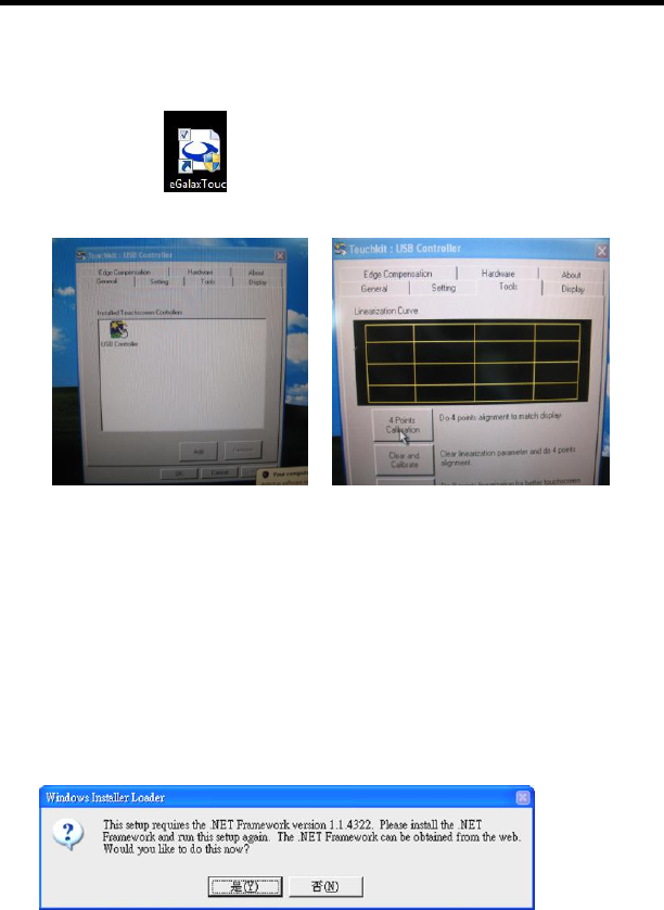
Using The Smart Panel to Calibrate The Screen
Select the icon on the desktop to launch the Calibration program and
the following panels will appear.
Select Tool, then select 4 Point Calibration. A red flashing X will appear
in the lower-left corner of the screen, then tap or click the X and hold it
until the green X appears. Follow the same steps to finish the other three
red X calibration.
Note: Make sure to calibrate the screen before your first screen rotation.
The First Installation
The following panel will appear if the user installs the software setup
procedure oneself. Users have to install Microsoft .NET Framework before
the first installation of Hot Key & Smart Panel Utilities.
Select “Yes” to install Microsoft .NET Framework immediately or users can
download Microsoft .NET Framework from Microsoft website later.
The Instructions Manual
36
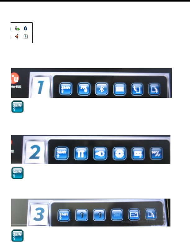
Using The Front Panel Hot Key Utility
Select the icon (low right Conner) in the Windows system tray or
Start Menu -> All Programs -> Hot Key & Smart Panel Utilities ->
Hot Key & Smart Panel Utilities to launch the program.
The following Primary Panel will appear:
Switches to nxet level functions.
The following Secondary Panel will appear:
Switches to next level functions.
The following Third Panel will appear:
Switches to next level functions.
Launch a Program via Primary, Secondary and Third Panels
Tap the icon twice to launch the program.
CHAPTER 4 – Specifications & Software
37
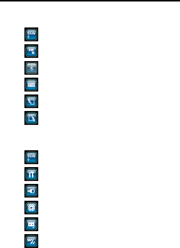
Primary Level Functions :
Switches to next level functions
Enable / Disable Touch Screen Function
Enables/Disables Blue Tooth Function
Invokes On-Screen Keyboard
Scroll Page Up
Scroll Page Down
Secondary Level Functions :
Switches to next level functions
System Warm Reboot (<Ctrl> + <Alt> + <Delete>)
Invokes Volume Control Utility
Invokes Windows Media Player
Record Audio (Start / Stop)
Enables/Disables Wireless Function
The Instructions Manual
38
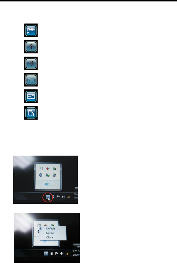
Third Level Functions :
Switches to next level functions
Enables/Disables Barcode Scanner Function
Barcode Scanner Trigger
Enables/Disables 3G Function
Screen Resolution
1024x768 1024x600
Screen Rotation
Define the Functions for Hot Key Utility
Tap the icon twice in the Windows system
tray to launch the defining program.
Left click the icon and select “Define” to
enter the setting menu.
CHAPTER 4 – Specifications & Software
39
1. Select the target Layer.
2. Select the target Icon.
3. Specify the file location of the function.
4. Tap “SAVE” to confirm the setting.
The First Installation
Please refer to the descriptions of “The First Installation” for “Using the Smart
Panel to Calibrate the Screen”.
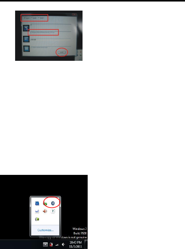
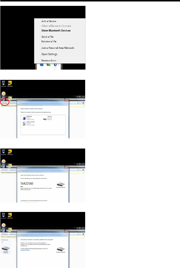
Using The Bluetooth Utility:
BlueSoleil allows the computer to wirelessly access a variety of Bluetooth
enabled digital devices, such as cameras, mobile phones, headsets, printers,
and GPS receivers. Users can also create networks and exchange data with
other Bluetooth enabled computers or PDAs.
First : Turn on your Bluetooth device
1. To launch the Blue Tooth icon (Red
circle) from the desktop.
The Instructions Manual
40
2. Select “Show Bluetooth Devices”.
3. Select “add device“ (Red Circle).
Some blue tooth devices were found and
listed out.
4. Select “Blue tooth Keyboard“ or
other devices.
5. Type the number or password for
configuration.
6. Selected Blue tooth device has
been successfully configured with
the computer.
CHAPTER 4 – Specifications & Software
41
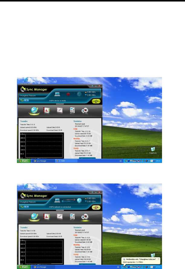
Making a 3.5G Connection and Disconnection
Select Start Menu -> All Programs -> Sync manager -> Connection Manager
Utility -> Connection Manager to launch the program. The system will launch
the program automatically after booting the computer.
Connection
Select <CONNECT> to make a connection.
Connected the internet
The Instructions Manual
42
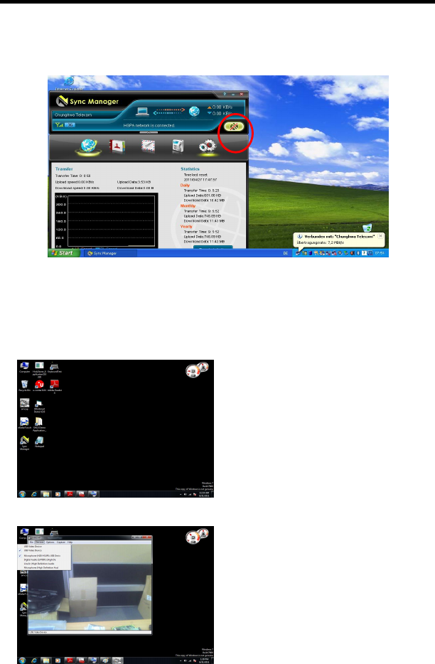
Disconnection
1. Select <DISCONNECT> to terminate the connection.
2. Select <Yes> to confirm the disconnection.
Using the CMOS Camera
1. Select “ AMCAP” ICON
2. Select “device“ and “USB Video
device“. The first bar for the front
camera and the second bar for the
rear camera.
CHAPTER 4 – Specifications & Software
43
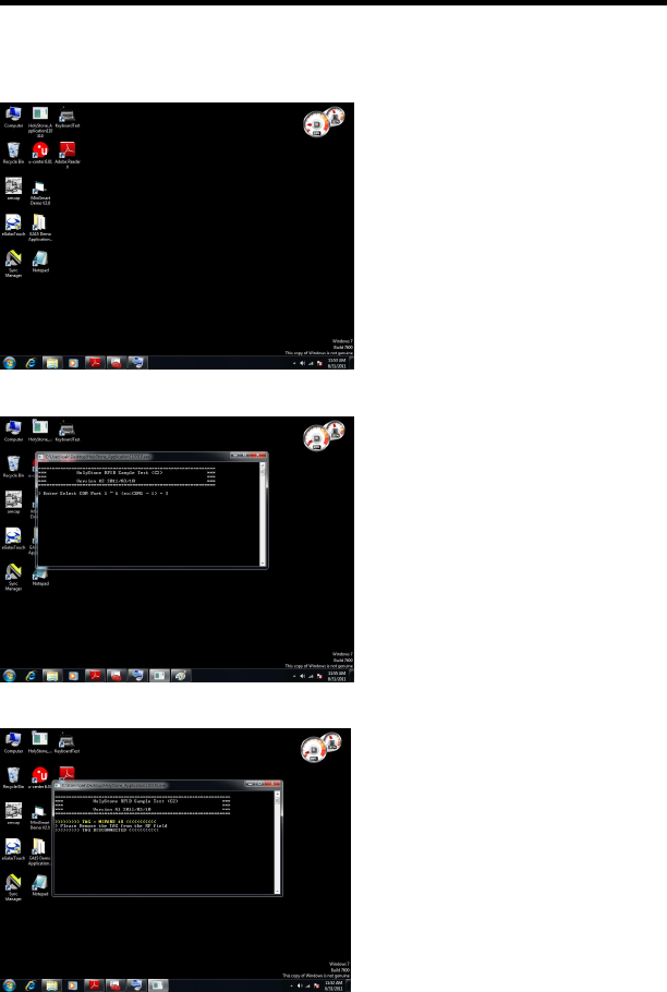
Using the RFID
1. Select “Holy Stone” ICON
2. Type “3” for the Select COM
Port.
3. Put your RFID card close to the
RFID Sensor.
The message “TAG = MIFARE 1K”
will be displayed, if the computer
accepts the RFID card.
The Instructions Manual
44
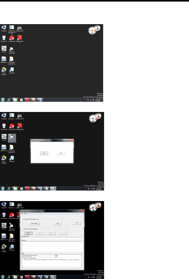
Using the Mini Smart Card
1. Select the “Mini Smart” icon.
2. Select the “ PC/SC ” button.
3. Insert the Mini Smart Card
into the slot and press the
“Connect to Card” button.
CHAPTER 4 – Specifications & Software
45
4. The detail information will
be displayed on the Result
dialog box.
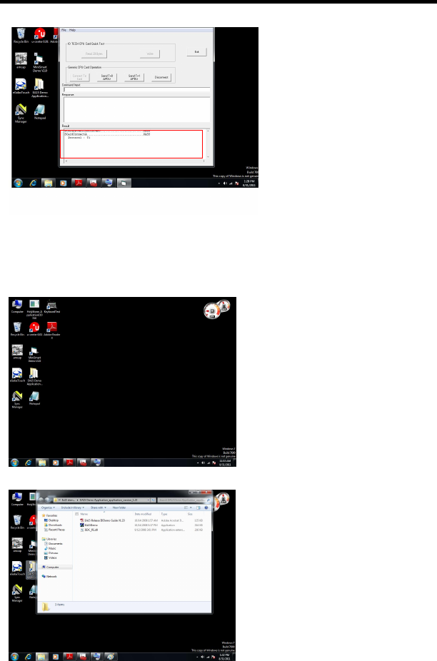
Using the Bar code Scanner
1. Select the “EA15 Demo” icon.
2. Select the “ EAISDemo”.
The Instructions Manual
46
3. Press the “Connect”
button and the status
information will be
displayed out.
4. Press the “Trigger”
button to enable the Bar
Code Scanner.
5. Scan the Bar Code Stick and the detail information will be displayed on the
“Decoded Label” dialog box.
CHAPTER 4 – Specifications & Software
47
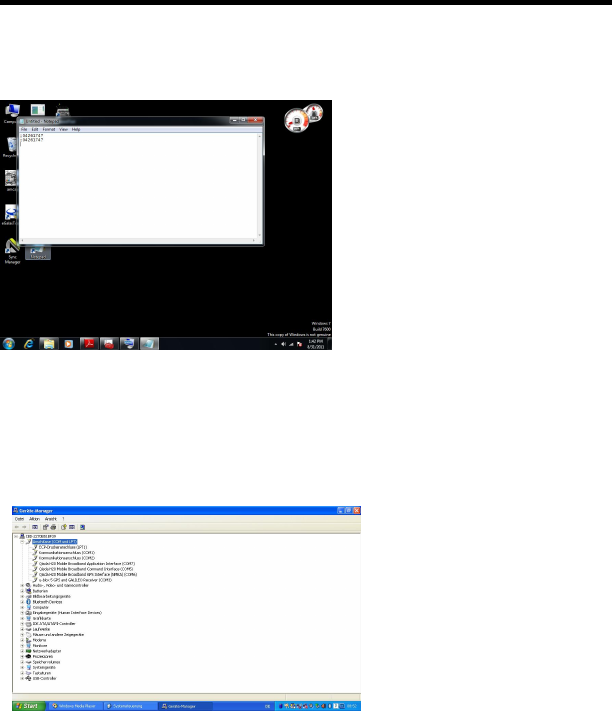
Using the MSR
1. Select the “NotePad” icon.
2. Insert the Cash Card or ATM
Card into the MSR slot.
3. The information will be
displayed on the screen.
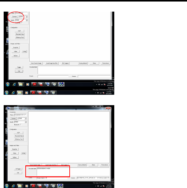
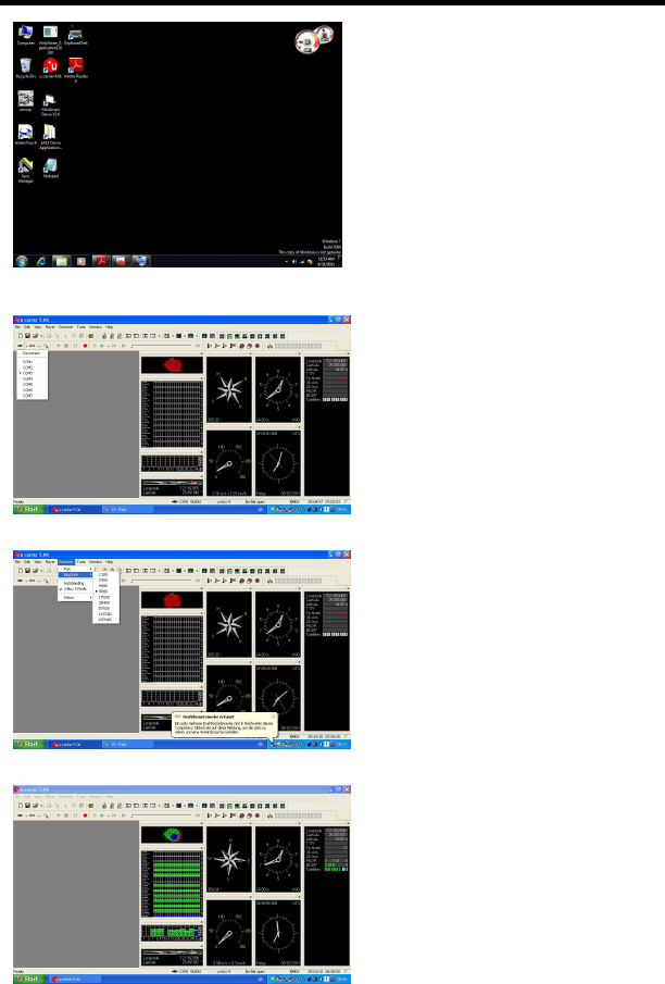
Using The GPS
Please disable the Bar Code Scanner and follow the steps below.
1. To Confirmed the GPS
COM port number at the
device manager.
(Path: start / Control pad / System / Hardware / Device Manager / COM & LTP)
The Instructions Manual
48
2. Select the “U-Center 6.01”
ICON.
3. Select COM3.
4. Select the Baud Rate.
5. Receive the Satellite Channel.
CHAPTER 4 – Specifications & Software
49
Using the Brightness Adjustment
The user can adjust the screen brightness with fingers while the computer
gets into the O.S. status. On the screen, to slide fingers from left to right or
right to left to change the screen brightness.