User Manual
page 1 of 6
Manual for i-BLE module
1. Introduction
i-BLE is a BLE module compliant with Bluetooth Low Energy (BLE) 4.1 specification optimized for
low-power applications. The core chipset is from Texas INSTRUMENTs, part number CC2640 and
Antenna is PCB pattern Ant for 2.4GHz.
2. Hardware Architecture:
2.1 Main Module / Chipset Information
Core Chipset : CC2640, Texas INSTRUMENTs , 2.4GHz RF transceiver compatible
with Bluetooth Low Energy (BLE) 4.1 specification.
Antenna :PCB pattern Antenna for 2.4GHz Band.
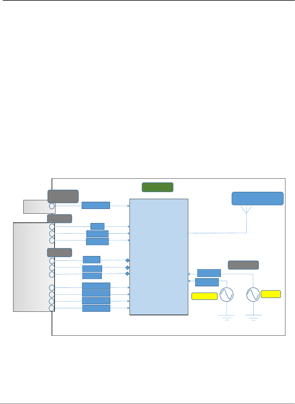
2.2 Circuit Block Diagram
The major internal and external block diagram of i-BLE Module is illustrated in Figure 1.
Figure 1. i-BLE Module block diagram and System Interface
CC2640
From Processor
Ext_Power
RST
Uart_RTS
Uart_CTS
Uart_RX
Uart_TX
JTAG_TMSC
JTAG_TCKC
JTAG_TDO
JTAG_TDI
DIO_0
VDDS_3.0V
Input Power
Ctrl_IF
SDIO_IF
Clock Source
PCB Antenna for 2.4GHz
Main_Clk
Sleep_Clk
32.768KHz
24MHz
BLE MODULE

page 2 of 6
3. Approval Statement
FCC Statement
To satisfy FCC exterior labeling requirements, the following text must be placed on the exterior
of the end product.
Contains Transmitter module FCC ID: OELBM001
The final end product must be labeled in a visible area with the following " Contains TX
FCC ID: OELBM001”
This equipment has been tested and found to comply with the limits for a Class B digital device,
pursuant to part 15 of the FCC Rules. These limits are designed to provide reasonable
protection against harmful interference in a residential installation. This equipment generates,
uses and can radiate radio frequency energy and, if not installed and used in accordance with
the instructions, may cause harmful interference to radio communications.
However, there is no guarantee that interference will not occur in a particular installation. If this
equipment does cause harmful interference to radio or television reception, which can be
determined by turning the equipment off and on, the user is encouraged to try to correct the
interference by one or more of the following measures:
- Reorient or relocate the receiving antenna.
- Increase the separation between the equipment and receiver.
- Connect the equipment into an outlet on a circuit different from that to which the receiver is
connected.
- Consult the dealer or an experienced radio/ TV technician for help.
This device complies with Part 15 of the FCC`s Rules. Operation is subject to the following two
Conditions:
1. This device may not cause harmful interference, and
2. This device must accept any interference received, including interference that may cause
undesirable operation.
FCC Radiation Exposure Statement;
This equipment complies with FCC radiation exposure limits set forth for an uncontrolled
environment.
This equipment should be installed and operated with minimum distance 20cm between the
radiator & body.
This module is intended for OEM integrator. The OEM integrator is still responsible for the FCC
compliance
Requirement of the end product, which integrates this module.
20cm minimum distance has to be able to be maintained between the antenna and the users for
the host
this module is integrated into. Under such configuration, the FCC radiation exposure limits set
forth for an
population / uncontrolled environment can be satisfied.
Any change or modifications not expressly approved by the manufacturer could voic the user’s
authority to
Operate this equipment.
In the users manual of the end of product, the end user has to be informed to keep at least 20cm

page 3 of 6
separation
with the antenna while this end product is installed and operated.
The end user has to be informed that the FCC radio-frequency exposure guidelines for an
uncontrolled environment can be satisfied. The end user has to also be informed that any
changes or modifications not expressly approved by the manufacturer could void the user’s
authority to operate this equipment.i f the size
Of the end product is smaller than 8x10cm,then additional FCC part15.19statement is required to
be available in the users manual; This device complies with Part15 of FCC rules.
IC Information
This device complies with Industry Canada license-exempt RSS standard(s). Operation is
subject to the following two conditions:
(1) this device may not cause interference, and
(2) this device must accept any interference, including interference that may cause undesired
operation of the device.
Cet appareil est conforme avec Industrie Canada exempts de licence standard RSS (s).
L'opération est soumise aux deux conditions suivantes:
(1) cet appareil ne peut causer d'interférences, et
(2) cet appareil doit accepter toute interférence, y compris les interférences qui peuvent
causer un mauvais fonctionnement de l'appareil.
The end product must be labeled to display the Industry Canada certification number of the
module.
Contains transmitter module IC: 21003-BM001
Le dispositif d'accueil doivent être étiquetés pour afficher le numéro de certification d'Industrie
Canada du module.
Contient module émetteur IC : 21003-BM001
IC Radiation Exposure Statement:
This equipment complies with IC RSS-102 radiation exposure limits set forth for an
uncontrolled environment. This equipment should be installed and operated with minimum
distance 20cm between the radiator & your body.
This module is intended for OEM integrator. The OEM integrator is still responsible for the
IC compliance requirement of the end product, which integrates this module.
20cm minimum distance has to be able to be maintained between the antenna and the
users for the host this module is integrated into. Under such configuration, the IC RSS- 102
radiation exposure limits set forth for an population/uncontrolled environment can be
satisfied.
The final end product must be labeled in a visible area with the following " Contains TX IC :
21003-BM001”
User Information
This device complies with FCC & IC radiation exposure limits set forth for an uncontrolled
environment. This device should be installed and must not be co-located or operating in
conjunction with any other antenna or transmitter.
This device is intended only for OEM integrators under the following conditions:

page 4 of 6
1) The antenna must be installed such that 20cm is maintained between the antenna and
users.
2) This module may not be co-located with any other transmitters or antennas.
As long as 2 conditions above are met, further transmitter test will not be required. However, the
OEM integrator is still responsible for testing their end-product for any additional compliance
requirements with this module installed. In the event that these conditions cannot be met, then
the FCC & IC authorizations are no longer
considered valid and the FCC ID cannot be used on the final product. In these circumstances,
the OEM integrator will be responsible for re-evaluating the end product including this module
and obtaining separate FCC & IC authorizations.
Cet appareil est conforme aux limites d'exposition rayonnement de la FCC et IC définies pour
un environnement
non contrôlé . Cet appareil doit être installé et ne doit pas être co- localisées ou opérant en
conjonction avec une autre antenne ou émetteur .
Cet appareil est conçu uniquement pour les intégrateurs OEM dans les conditions suivantes :
1 ) L' antenne doit être installée de telle sorte que 20 cm est maintenue entre l'antenne et les
utilisateurs .
2 ) Ce module ne peut pas être co-localisé avec d'autres émetteurs ou des antennes .
Tant que deux conditions ci-dessus sont remplies , nouvel essai de l'émetteur ne sera pas tenu .
Cependant , l'intégrateur OEM est toujours responsable de tester leur produit final pour les
exigences de conformité supplémentaires avec ce module installé .Dans le cas où ces
conditions ne peuvent être remplies, les autorisations de la FCC et IC ne sont plus considérés
comme valides et l'ID FCC ne peuvent pas être utilisés sur le produit final . Dans ces
circonstances , l'intégrateur OEM sera chargé de réévaluer le produit final incluant ce module et
l'obtention des autorisations de la FCC et IC distincts .
Any changed or modifications not expressly approved by the party responsible for compliance
could void the user`s authority to operate this equipment.
Toute changé ou modifications non expressément approuvés par la partie responsable de la
conformité
pourraient annuler l'utilisateur `autorité de faire fonctionner cet équipement.
page 5 of 6
4. Installation
This i-BLE module must be installed in a device and not allow the user to replace nor modify
it.

page 6 of 6
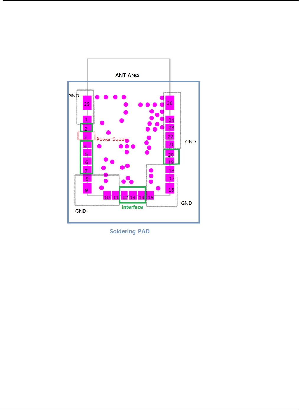
5.1 PIN Description
PIN No. Symbol Description
1 GND GND
2 DIO_0 Data Bus for Host
3 VDDS Supply 3.0V
4 JTAG_TMSC data Bus for SW Download
5 JTAG_TCKC data Bus for SW Download
6 JTAG_TDO data Bus for SW Download
7 JTAG_TDI data Bus for SW Download
8 GND GND
9 GND GND
10 GND GND
11 GND GND
12 RST Reset for CC2640
13 Uart_RX Data Bus for Host
14 Uart_TX Data Bus for Host
15 GND GND
16 GND GND
17 GND GND
18 GND GND
19 Uart_RTS Data Bus for Host
20 Uart_CTS Data Bus for Host
21 GND GND
22 GND GND
23 GND GND
24 GND GND
25 GND GND
26 GND GND