iComm Semiconductor M169 WIFI Module User Manual 15 M169 UserMan
iComm Semiconductor Co.,Ltd. WIFI Module 15 M169 UserMan
15_M169 UserMan

Proprietary and confidential information. Copyright © iComm Corporation. All rights reserved.
1
M169 WIFI Module specification
Features
WI-FI Features
Support 802.11 b/g/n Wireless standards
Support WEP、WPA/WPA2
Support Station or Soft AP mode
Andes Technology N10 processor,128K ROM and 192KB SRAM for instruction and data
SRAM in total
Integrate 16Mbit SPI flash in package
Support OTA
PCB ANT
Operating Voltage:DC 3.0V-3.6V
External port
2X UART(1xDebug URAT)
4X ADC
9X GPIO (include1XI2C, 4XPWM,1XSPI_M)
Work Temperature:-20℃ ~ +80℃
Module Size:15mmX18mm,SMD package
Application
intelligent lighting
Intelligent Transportation System
Smart home appliances
Intelligent security
industrial automation

Proprietary and confidential information. Copyright © iComm Corporation. All rights reserved.
2
Contents
1. Product introduction ............................................................................................... 2
Block diagram of module hardware .................................................................. 3
1.1. Pin definition ................................................................................................. 3
1.2. Pin Assignment ............................................................................................ 5
1.3. Pin Descriptions ........................................................................................... 5
2. Electric parameter .............................................. 7
2.1 Absolute Maximum Ratings .................................... 7
2.2 Operating Conditions ......................................... 7
2.3 Environmental Ratings ........................................ 7
2.4 Storage Condition ............................................ 7
3. Module assembly ................................................. 8
3.1 Module layout ................................................ 8
Proprietary and confidential information. Copyright © iComm Corporation. All rights reserved.
3
1. Product introduction
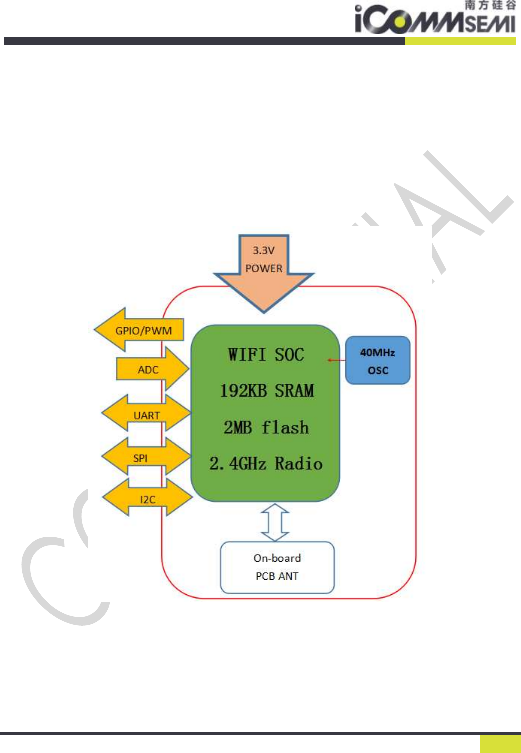
The Module include WLAN MAC、Baseband、RF,and the Processor speed up 160MHz.The
WIFI SoC has 128K ROM and 192KB SRAM for instruction and data SRAM,also integrate 2MB
SPI flash 。The whole module is supplied with 3.3V power.Use SMT installation.
The following figure is the hardware block diagram of the module:
Block diagram of module hardware
Proprietary and confidential information. Copyright © iComm Corporation. All rights reserved.
4
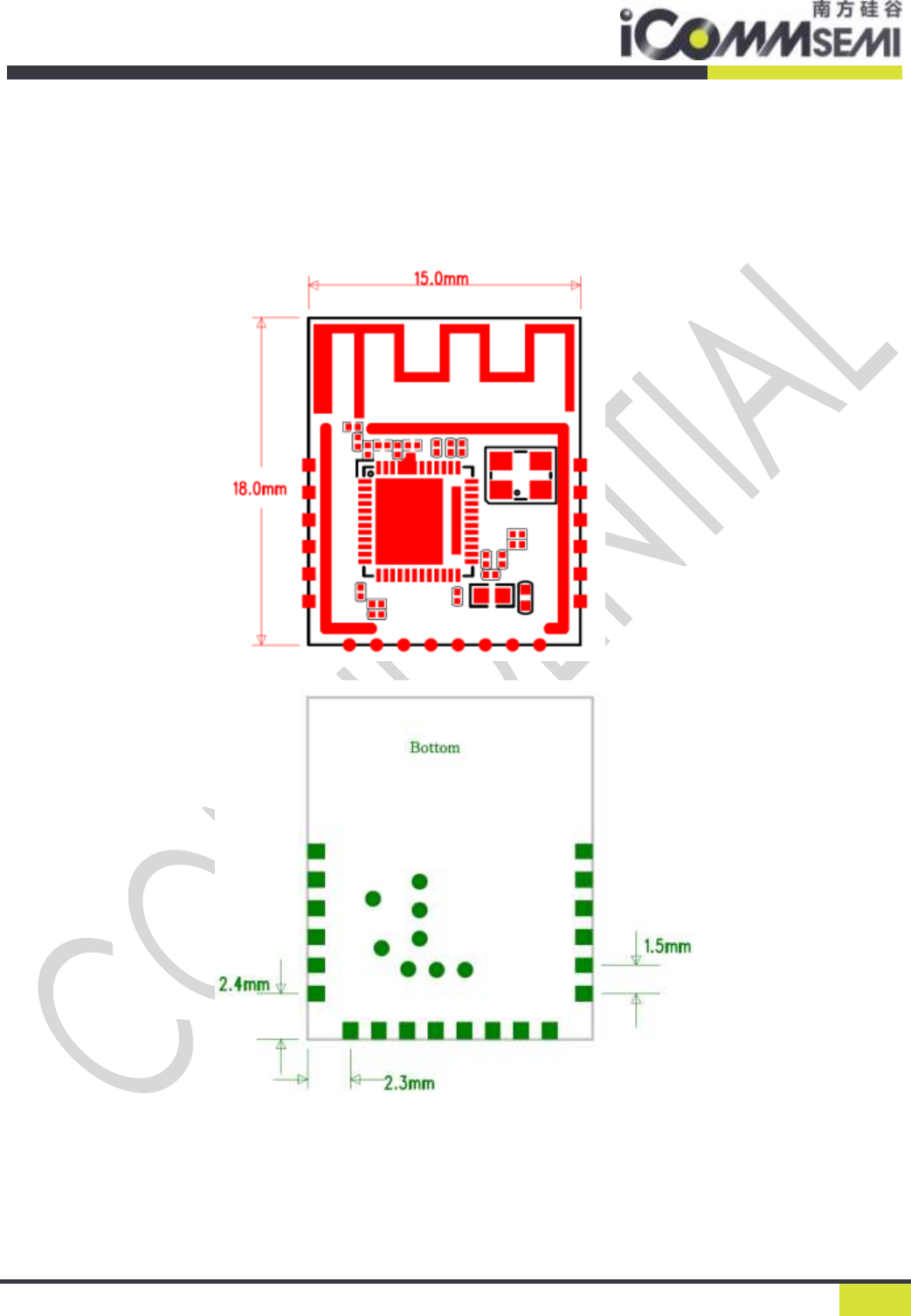
1.1. Pin definition
The module uses the DIP package and stamp hole package two kinds of interface design
scheme to facilitate customer debugging。
Figure1 Machine size map
Proprietary and confidential information. Copyright © iComm Corporation. All rights reserved.
5
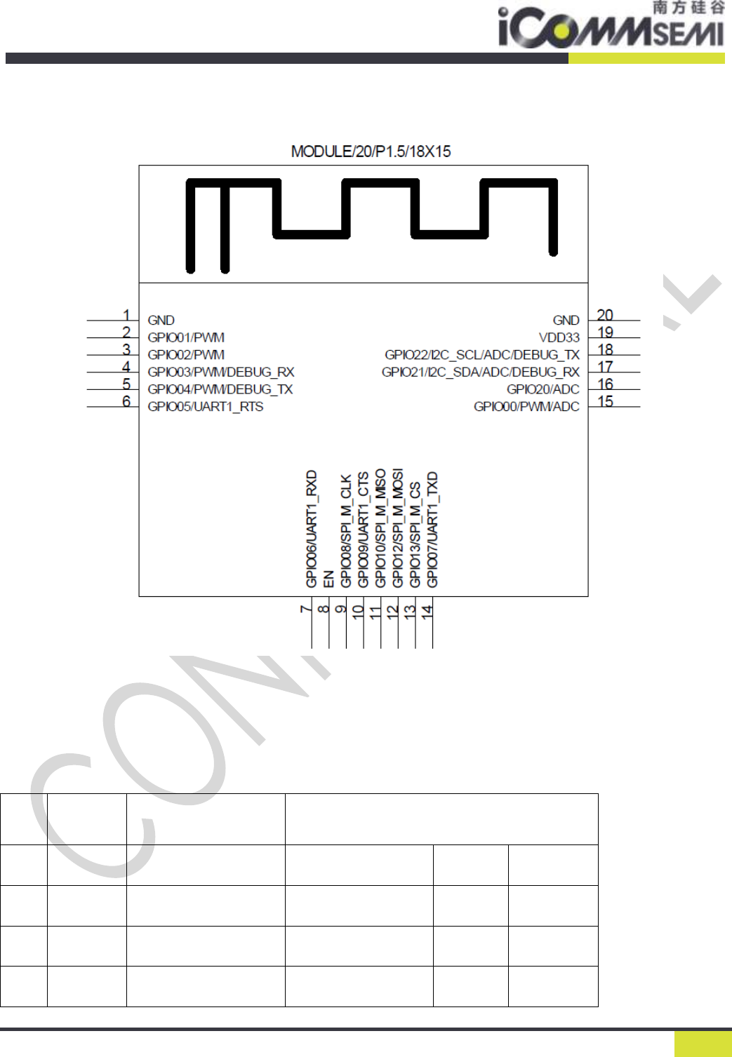
1.2. Pin Assignment
Figure2 M169 Pin Assignment
1.3. Pin Descriptions
Pin
NO.
Pin
Name
Description
Programmable functions
1
GND
Ground
2
GPIO01
PWM1
3
GPIO02
PWM2
4
GPIO03
Debug_UART_RX
PWM3
Proprietary and confidential information. Copyright © iComm Corporation. All rights reserved.
6
5
GPIO04
Debug_UART_TX
PWM4
6
GPIO05
UART1_RTS
7
GPIO06
UART1_RXD
8
EN
Reset signal and chip
enable
9
GPIO08
SPI_M_CLK
10
GPIO09
UART1_CTS
11
GPIO10
SPI_M_MISO
12
GPIO12
SPI_M_MOSI
13
GPIO13
SPI_M_CS
14
GPIO07
UART1_TXD
15
GPIO00
PWM0
ADC
16
GPIO20
ADC
17
GPIO21
I2C_SDA
Debug_
UART_R
X
ADC
18
GPIO22
I2C_SCL
Debug_
UART_T
X
ADC
19
VDD33
3.3V power supply
20
GND
Ground
Proprietary and confidential information. Copyright © iComm Corporation. All rights reserved.
7
2. Electric parameter
2.1 Absolute Maximum Ratings
The absolute maximum ratings in Table 2-1 indicate levels where permanent damage to the device can occur,
even if these limits are exceeded for only a brief duration. Functional operation is not guaranteed under these
conditions. Operation at absolute maximum conditions for extended periods can adversely affect long-term reliability
of the device.
Table 2-1 Absolute Maximum Rating
2.2 Operating Conditions
Table 2-2 Recommended Operating Conditions and DC Characteristics
Symbol
Description
MIN
TYP
MAX
Unit
VDD
Module input power
3.0
3.3
3.6
V
VIL
Input Low(VDDIO=3.3V)
-0.3
0.8
V
VIH
Input High(VDDIO=3.3V)
2
3.6
V
VOL
output Low(VDDIO=3.3V)
0.4
V
VOH
output High(VDDIO=3.3V)
2.4
V
2.3 Environmental Ratings
Table 2-3 Environmental Ratings
Characteristic
Conditions/Comments
Value
Units
Ambient Temperature
Functional operation
-20 to +80
°C
Max welding temperature
IPC/JEDEC J-STD-020
260
°C
2.4 Storage Condition
Characteristic
Conditions/Comments
Value
Units
Symbol
Description
Max Rating
Unit
VDD
Input power
-0.3 to 3.6
V
Proprietary and confidential information. Copyright © iComm Corporation. All rights reserved.
8
Storge Temperature
-40 to +125
°C
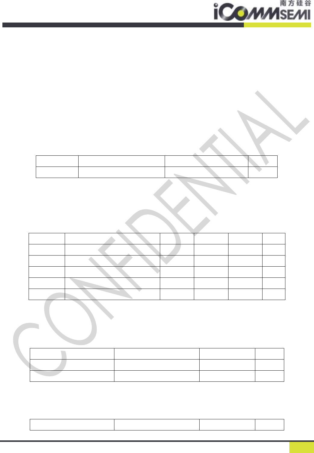
3. Module assembly
3.1 Module layout
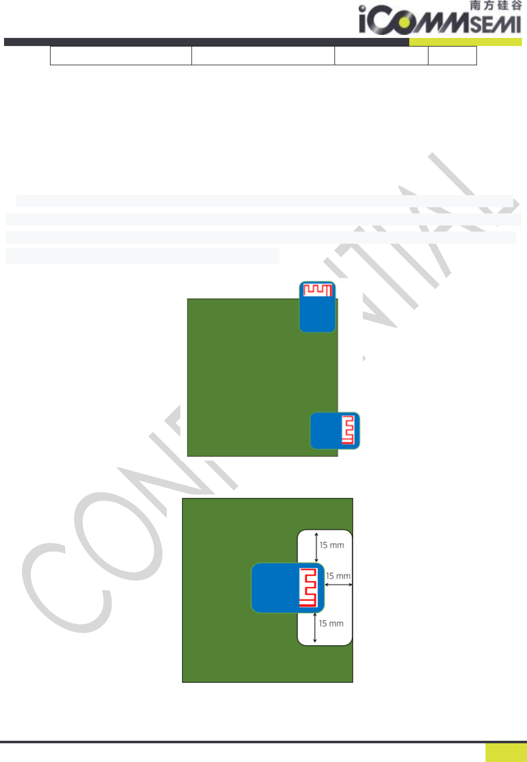
When the module used the on-board antenna , it is necessary to ensure that the module antenna extends
directly from the bottom plate, and the antenna that cannot extend the bottom plate must also be hollowed out
on the bottom plate, and the distance from other metal devices should be at least 16mm.The following figure
shows the placement of the protruding edge of the module:
Figure 3 Schematic diagram of module installation position
Figure4 Antenna hollow area requirements

Proprietary and confidential information. Copyright © iComm Corporation. All rights reserved.
9
FCC Warning
This device complies with Part 15 of the FCC Rules. Operation is subject to the following two conditions:
(1) This device may not cause harmful interference, and (2) this device must accept any interference
received, including interference that may cause undesired operation.
NOTE 1: This equipment has been tested and found to comply with the limits for a Class B digital device,
pursuant to part 15 of the FCC Rules. These limits are designed to provide reasonable protection against
harmful interference in a residential installation. This equipment generates, uses and can radiate radio
frequency energy and, if not installed and used in accordance with the instructions, may cause harmful
interference to radio communications. However, there is no guarantee that interference will not occur in
a particular installation. If this equipment does cause harmful interference to radio or television
reception, which can be determined by turning the equipment off and on, the user is encouraged to try
to correct the interference by one or more of the following measures:
- Reorient or relocate the receiving antenna.
- Increase the separation between the equipment and receiver.
-Connect the equipment into an outlet on a circuit different from that to which the receiver is
connected.
-Consult the dealer or an experienced radio/TV technician for help.
NOTE 2: Any changes or modifications to this unit not expressly approved by the party responsible for
compliance could void the user's authority to operate the equipment.
FCC Radiation Exposure Statement:
This equipment complies with FCC radiation exposure limits set forth for an uncontrolled environment.
End users must follow the specific operating instructions for satisfying RF exposure compliance.
Note 1: This module certified that complies with RF exposure requirement under mobile or fixed
condition, this module is to be installed only in mobile or fixed applications.
A mobile device is defined as a transmitting device designed to be used in other than fixed locations and
to generally be used in such a way that a separation distance of at least 20 centimeters is normally
maintained between the transmitter's radiating structure(s) and the body of the user or nearby persons.
Transmitting devices designed to be used by consumers or workers that can be easily re-located, such as
wireless devices associated with a personal computer, are considered to be mobile devices if they meet
the 20 centimeter separation requirement.

Proprietary and confidential information. Copyright © iComm Corporation. All rights reserved.
10
A fixed device is defined as a device is physically secured at one location and is not able to be easily
moved to another location.
Note 2: Any modifications made to the module will void the Grant of Certification, this module is limited
to OEM installation only and must not be sold to end-users, end-user has no manual instructions to
remove or install the device, only software or operating procedure shall be placed in the end-user
operating manual of final products.
Note 3: Additional testing and certification may be necessary when multiple modules are used.
Note 4: The module may be operated only with the antenna with which it is authorized. Any antenna
that is of the same type and of equal or less directional gain as an antenna that is authorized with the
intentional radiator may be marketed with, and used with, that intentional radiator.
Note 5: To ensure compliance with all non-transmitter functions the host manufacturer is responsible
for ensuring compliance with the module(s) installed and fully operational. For example, if a host was
previously authorized as an unintentional radiator under the Supplier’s Declaration of Conformity
procedure without a transmitter certified module and a module is added, the host manufacturer is
responsible for ensuring that the after the module is installed and operational the host continues to be
compliant with the Part 15B unintentional radiator requirements. Since this may depend on the details
of how the module is integrated with the host, (iComm Semiconductor Co., Ltd.) shall provide guidance
to the host manufacturer for compliance with the Part 15B requirements.
Note 6: FCC ID label on the final system must be labeled with “Contains FCC ID: 2AQ5K-M169” or
“Contains transmitter module FCC ID: 2AQ5K-M169”.
Note 7: For all products market in US, OEM has to limit the operation channels in CH1 to CH11 for 2.4G
band by supplied firmware programming tool. OEM shall not supply any tool or info to the end-user
regarding to Regulatory Domain change.