IOptron 7201 CEM60 Manual V1.0x User To The 87879687 Df0e 476a 8389 A7a8566a62f9
User Manual: iOptron 7201 to the manual
Open the PDF directly: View PDF ![]() .
.
Page Count: 46
iOptron® CEM60 Center-Balanced Equatorial Mount
Instruction Manual
Product #7200 and#7201

2
Read the included CEM60 Quick Setup Guide BEFORE taking the mount out of the case!
This product is a precision instrument and uses a magnetic gear meshing mechanism. Please read
the included QSG before assembling the mount. Please read the entire Instruction Manual before
operating the mount.
You must hold the mount firmly when disengaging or adjusting the gear switches. Otherwise
personal injury and/or equipment damage may occur. Any worm system damage due to improper
gear meshing/slippage will not be covered by iOptron limited warranty.
If you have any questions please contact us at support@ioptron.com
WARNING!
NEVER USE A TELESCOPE TO LOOK AT THE SUN WITHOUT A PROPER FILTER!
Looking at or near the Sun will cause instant and irreversible damage to your eye.
Children should always have adult supervision while using a telescope.
3
Table of Content
Table of Content ................................................................................................................................................. 3
1. CEM60 Overview ........................................................................................................................................... 5
2. CEM60 Terms ................................................................................................................................................ 6
2.1. Parts List .................................................................................................................................................. 6
2.2. Assembly Terms ...................................................................................................................................... 7
2.3. CEM60 Mount Ports ................................................................................................................................ 7
2.4. CEM60 Gear Switches ............................................................................................................................ 8
2.5. CEM60 Cable Management .................................................................................................................... 8
2.6. Go2Nova® 8407 Hand Controller ........................................................................................................... 9
2.6.1. Key Description ................................................................................................................................ 9
2.6.2. The LCD Screen ............................................................................................................................. 10
3. CEM60 Mount Assembly ............................................................................................................................. 12
3.1. Introduction ........................................................................................................................................... 12
3.2. CEM60 Mount Assembly ...................................................................................................................... 12
4. Getting Started .............................................................................................................................................. 22
4.1. Setting the Mount and Performing Polar Alignment ............................................................................. 22
4.2. Manual Operation of the Mount ............................................................................................................ 22
4.3. One Star Alignment ............................................................................................................................... 22
4.4. Go to the Moon and Other Stars ............................................................................................................ 22
4.5. Star Identifying Function ....................................................................................................................... 23
4.6. Turning Off the Mount .......................................................................................................................... 23
4.7. Putting the Mount Back into the Carrying Case .................................................................................... 23
5. Complete Functions of Go2Nova® 8407 Hand Controller ........................................................................... 24
5.1. Select and Slew ...................................................................................................................................... 24
5.1.1. Solar System ................................................................................................................................... 24
5.1.2. Deep Sky Objects ........................................................................................................................... 24
5.1.3. Stars ................................................................................................................................................ 24
5.1.4. Comets ............................................................................................................................................ 24
5.1.5. Asteroids ......................................................................................................................................... 24
5.1.6. Constellations ................................................................................................................................. 25
5.1.7. Custom Objects .............................................................................................................................. 25
5.1.8. Enter R.A. DEC .............................................................................................................................. 25
5.2. Sync to Target ........................................................................................................................................ 25
5.3. Align ...................................................................................................................................................... 25
5.3.1. Pole Star Position ........................................................................................................................... 25
5.3.2. Polar Align ...................................................................................................................................... 25
5.3.3. One Star Alignment ........................................................................................................................ 26
5.3.4. Solar System Align ......................................................................................................................... 26
5.3.5. Multi-Star Align ............................................................................................................................. 26
5.3.6. 2-Star Polar Align ........................................................................................................................... 26
5.3.7. Display Axes Error ......................................................................................................................... 26
5.4. Settings .................................................................................................................................................. 27
5.4.1. Set Time & Site .............................................................................................................................. 27
5.4.2. Set Display & Beep ........................................................................................................................ 27
5.4.3. Set Guider Rate ............................................................................................................................... 27
5.4.4. Set Tracking Rate ........................................................................................................................... 28
5.4.5. Set Parking Position ....................................................................................................................... 28
5.4.6. Meridian Treatment ........................................................................................................................ 28
4
5.4.7. Track Below Horizon ..................................................................................................................... 28
5.4.8. Set Eyepiece Light .......................................................................................................................... 28
5.4.9. Heating Controller .......................................................................................................................... 28
5.5. Electric Focuser ..................................................................................................................................... 28
5.6. PEC Option ............................................................................................................................................ 29
5.6.1. PEC Playback ................................................................................................................................. 29
5.6.2. Record PEC .................................................................................................................................... 29
5.7. Telescope Motion .................................................................................................................................. 29
5.7.1. Park Scope ...................................................................................................................................... 29
5.7.2. Search Zero Pos. ............................................................................................................................. 29
5.8. Edit User Objects ................................................................................................................................... 30
5.8.1. Enter A New Comet ....................................................................................................................... 30
5.8.2. Enter Other Objects or Observation List ........................................................................................ 30
5.9. Firmware Information ........................................................................................................................... 31
5.10. Goto Zero Position .............................................................................................................................. 31
6. Maintenance and Servicing .......................................................................................................................... 32
6.1. Maintenance .......................................................................................................................................... 32
6.2. iOptron Customer Service ..................................................................................................................... 32
6.3. Product End of Life Disposal Instructions ............................................................................................ 32
6.4. Battery Replacement and Disposal Instructions .................................................................................... 32
Appendix A. Technical Specifications ............................................................................................................. 33
Appendix B. Go2Nova® 8407 HC MENU STRUCTURE .............................................................................. 34
Appendix C. Firmware Upgrade ...................................................................................................................... 37
Appendix D. Computer Control a CEM60 Mount ........................................................................................... 38
Appendix E. Go2Nova® Star List ..................................................................................................................... 39
IOPTRON TWO YEAR TELESCOPE, MOUNT, AND CONTROLLER WARRANTY ............................ 46
Ver. 1.0
iOptron reserves the rights to revise this instruction without notice. Actual color/contents/design/function may differ from those described in this
instruction.
5
1. CEM60 Overview
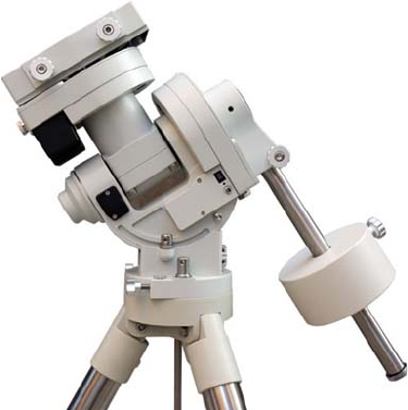
Welcome to a new type of EQ mount- The iOptron® Center-Balanced Equatorial Mount, CEM! Its unique
balance design puts the payload at the center of gravity allowing for greater natural stability. This also
means the mount is extremely light compared to its payload—a nice benefit when setting up at a remote
site. The adjustable counterweight bar prevents the counterweight from getting in the way of the tripod or
pier when operating at a low latitude position. Polar aligning is quick and accessible all the time since the
polar scope is not blocked by the declination shaft.
The CEM60TM mount is equipped with the most advanced GOTONOVA® GOTO technology, making it one
of the most powerful and accurate GOTO mounts available. The database of a Go2Nova® 8407 hand
controller has over 300,000 objects. The other features include a magnetically loaded gear system, gear
switches on both R.A. and DEC axes, a screw/worm type latitude adjuster and a built-in or customized
cable management system. The CEM60-- a new category (and payload capacity) of mounts for viewing and
astrophotography!
Features:
A new design, center-balanced equatorial mount (CEM) for maximum payload and minimum mount
weight
Specialized astrophotography mount ideal for both visual observers and astro-photographers
Patent pending non-contact magnetically loaded gear system
Payload of 60 lbs (27.2 kg) with the mount-only weight of 27 lbs (12.3 kg)
Gear switches on both R.A. and DEC axes for easy balancing
Adjustable counterweight shaft for low latitude operation
Screw/worm type latitude adjuster for precision adjustments
Milling machine tooling vise type latitude bearing and lock system for rock solid positioning
Azimuth fine adjusters for easy azimuth adjustment
Precision stepper motor with 0.06 arc-sec accuracy for precise GOTO and accurate tracking
Permanent periodic error correction (PPEC) (#7200) or Real-time periodic error correction (RPEC)
(#7201)
iOptron AccuAligningTM calibrated polar scope with dark-field illumination and easy polar alignment
procedure for fast and accurate polar alignment
Polar alignment routine for those who can't see the Pole Star
Go2Nova® 8407 controller with Advanced GOTONOVA® GOTO Technology an built-in heater
Integrated ST-4 compatible autoguiding port
Built-in 32-channel Global Positioning System (GPS)
Built-in or customized cable management system
Spring loaded Vixen/Losmandy dual saddle
150mm base size to match optional 2 inch heavy-duty stainless steel tripod (8kg) or 42/48 inch pier
Optional PowerWeightTM rechargeable battery pack

6
2. CEM60 Terms
2.1. Parts List1
SHIPPING CONTENTS
There are two shipping boxes for a CEM60 mount. One box contains an aluminum carrying case
with a mount, either CEM60 (#7200) or CEM60-EC (#7201) mount head, a hand controller, a counterweight
shaft and accessories, including a counterweight pin and locking screws. The other box is for a 21lbs (9.5kg)
counterweight. The contents are listed below:
iOptron
® CEM60 telescope mount (#7200, with silver adjustment knobs) or iOptron® CEM60-EC
mount (high precision model #7201, with red adjustment knobs)
Go2Nova® 8407+ Hand Controller
One 21lbs (9.5 kg) counterweight
Stainless steel counterweight shaft
Dark field illuminating LED cable
AC adapter (100V-240V)
HC Controller Cable X 1
Serial cable (RS232 toRJ9)
12V DC power cable with car charger
Aluminum carrying case
Quick Start Guide
OPTIONAL PARTS
2” tripod (#8021ACC)
42 inch pier (#8033) /48 inch pier (#8030)
MiniPier (#8032)
PowerWeightTM rechargeable counterweight battery (#8128)
ONLINE CONTENTS (click under “Support” menu) www.iOptron.com
Quick Start Guide
This manual
Tips for set up
Hand controller and mount firmware upgrades (check online for latest version)
.NET ASCOM driver
Reviews and feedback from other customers
Accessories
1 US market only. Actual contents may vary.
7
2.2. Assembly Terms
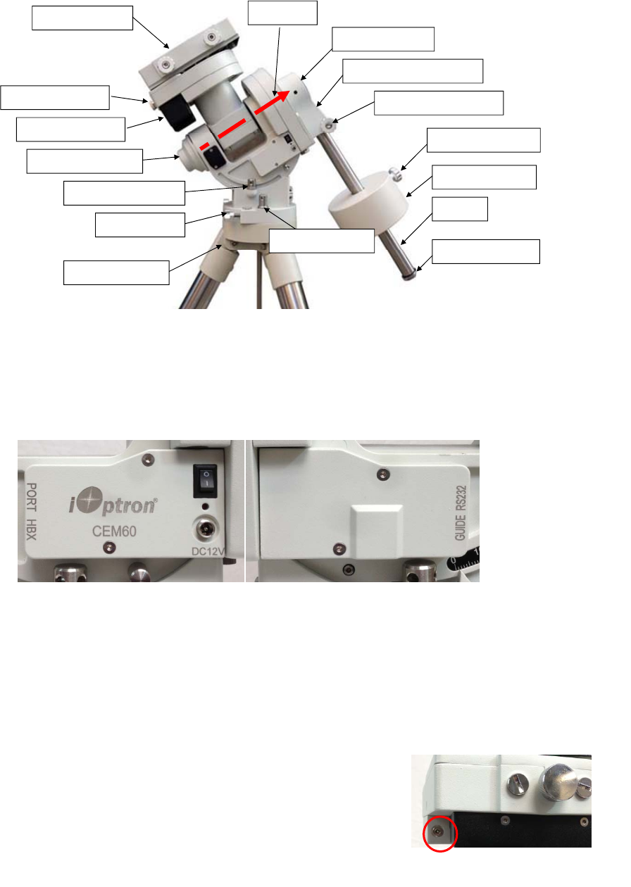
Figure 1.CEM60 assembly
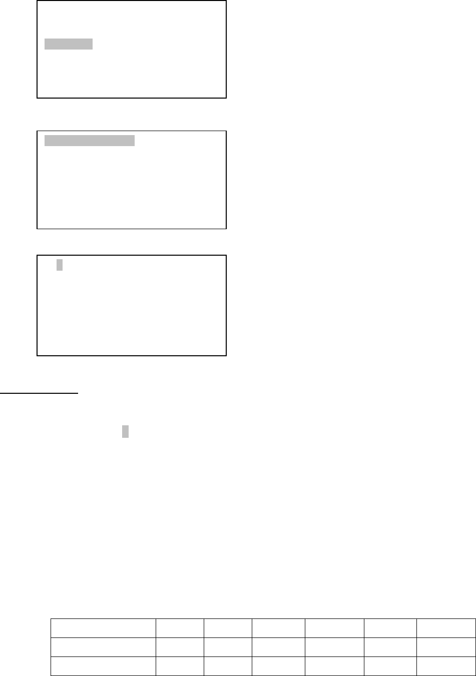
2.3. CEM60 Mount Ports
Ports on the mount
Figure 2. Ports on a CEM60 mount
I/O: Power Switch
DC 12V: DC power socket for the mount
PORT: iOptron port for connecting to other iOptron accessories, such as an electronic focuser or
a planetary dome control. DO NOT plug your ST-4 guiding camera cable into it. It may damage
the mount or guiding camera electronics.
HBX (Hand Box): For connecting to an 8407 Hand Controller
GUIDE: ST-4 compatible autoguiding port
RS232: Serial port for mount-computer control and
firmware upgrade
On DEC unit:
Reticle: Power supply for the polar scope dark field
illumination LED, or illuminated eyepiece
Dovetailsaddle
DECdriveunit
CWmountinghousing
CWsafetyscrew
CWbar
Counterweight
CWlockingscrew
Shaftpositionscrew
Polaraxiscover
DECgearswitch
Polarscopecover
Az.adj.knob
Az.Lockingnut
Lat.Lockingclamp
Optionaltripod
Polaraxis
Figure 3. LED reticle on DEC unit
8
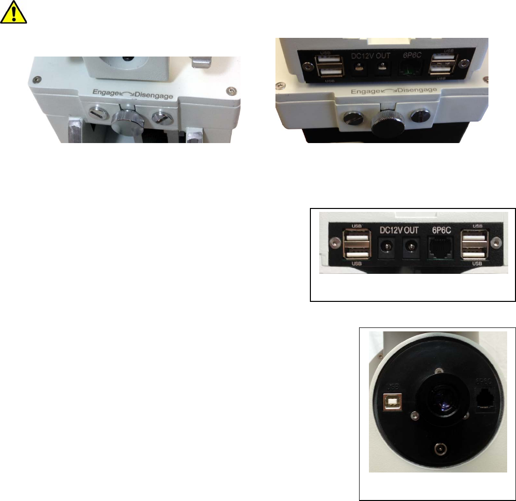
2.4. CEM60 Gear Switches
The CEM gear system utilizes a magnetic force system for optimal gear meshing. Fully turn the
Gear Switch clockwise to disengage the worm from the worm wheel. Turn the Gear Switch
counterclockwise to engage the worm to worm wheel, as indicated on the mount. The Gear Switch MUST
NOT be left in a position that is in between the Engaged and Disengaged positions. Setting the Gear Switch
in between states may damage the worm or worm wheel.
WARNING: Never disengage or adjust the Gear Switches without holding the mount firmly!
Personal injury and/or equipment damage may happen.
Figure 4. CEM60 R.A. (left) and DEC (right) gear switches
2.5. CEM60 Cable Management
The CEM60 mount has a pre-wired instrument panel
that allows the user to connect his imaging gears without
having the wires/cables dragged all over the mount when the
mount is slewing or tracking. As shown in Figure 5, the
Instrument Panel has the following:
2X 12V power outlets for powering the CCD
camera or electric focuser
4X USB 2.0 port with Type A connector for
connecting to accessories.
1X 6P6C port which can be used to bridge the guiding port or
accessories with a 6P6C/6P4C plug
The USB hub is a non-powered one. It will draw power from a
source, such a computer USB port. Therefore, the maximum usable USB
ports might be limited, depending on the power consumption of the
accessories.
The ports on the instrument panel are connected to the input
panel located next to the polar scope, as shown in Figure 6.
1X 12V power input (5A max.)
1X USB 2.0 port with Type B connector
1X 6P6C port
In the event where a user would like to wire his own cables, he can remove the dovetail saddle. Next he
needs to remove the polar scope and run the cables through the polar scope opening. Solder the cables
onto the instrument pane. When reinstalling the dovetail saddle, make sure that the STOPPER and the
arrow is pointed to front, as shown in Figure 7.
Figure 5. Instrument panel
Figure 6. Input panel
9
Figure 7. Stopper on a dovetail saddle
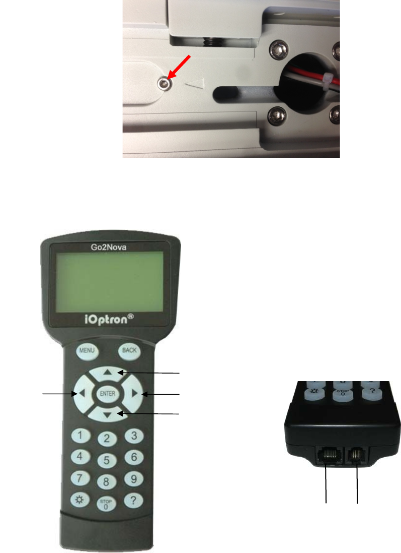
2.6. Go2Nova® 8407 Hand Controller
Figure 8. Go2Nova 8407 hand controller
The Go2Nova® 8407 hand controller (HC) shown in Figure 8 is the standard controllers that is used
on the CEM60 mount. It has an integrated temperature controller that ensures it can be operated at -20ºC
(-4ºF). It has a large LCD screen, function keys, direction keys and number keys on the front; a red LED
reading light on the back; and a HBX port (6-pin) and a serial port (4-pin) at the bottom.
2.6.1. Key Description
MENU Key: Press “MENU” to enter the Main Menu.
HBX
Port
Serial
Port
R.A.+ R.A.-
DEC-
DEC+
10
BACK Key: Move back to the previous screen, or end/cancel current operation, such as slewing.
ENTER Key: Confirm an input, go to the next menu, select a choice, or slew the telescope to a
selected object.
Arrow (▲▼◄►) Keys: The arrow keys are used to control the movement of DEC and R.A. axes.
Press and hold ▲(DEC+),▼(DEC-) buttons to move a telescope along the DEC direction,
◄(R.A.+), ►(R.A.-) to move a telescope along the R.A. direction. They are also used to browse
the menu or move the cursor while in the menu. Press and hold down an arrow key for a fast
scrolling.
Number Keys: Input numerical values. Also used to adjust speeds (1: 1X; 2: 2X; 3: 8X; 4: 16X; 5:
64X; 6: 128X; 7: 256X; 8: 512X; 9: MAX)
Light Key(☼): Turns on/off the red LED reading light on the back of the controller.
? Key: Identify and display bright stars or objects where the telescope points to.
STOP/0 Key: Stop the mount during GOTO. Also toggling between start and stop tracking.
HBX (Handbox) port: connect the HC to the CEM60 mount using a 6-wire RJ11 cable.
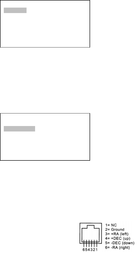
Serial port: connect the HC to a Computer via a RS232 to 4-wire RJ-9 cable. The pin out of the
serial port is shown in Figure 9.
Figure 9. Serial port pin out on an 8407 hand controller
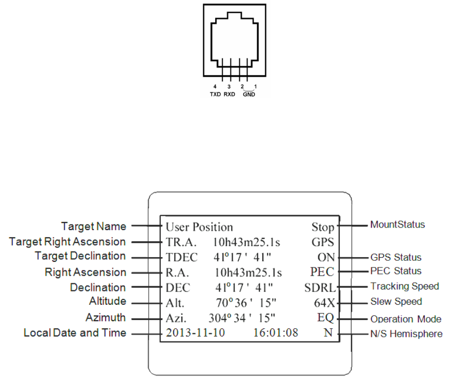
2.6.2. The LCD Screen
The 8407 HC has a large 8-line, 21-character per line LCD screen, which displays all the information
as shown in Figure 10. The user interface is simple and easy to operate.
Figure 10. 8407 HC LCD Information Screen
1. Target Name/Mount Position: displays the name of the target that telescope is currently pointed to or
the current mount position.
Zero Position: The position when the mount is turned on. Or when the mount is moved to Zero
Position using “Goto Zero Position” command;
User Position: The mount is pointed to a user defined position, which could be a real sky object
or just simply a position defined by pressing an arrow key.
11
An object name, such as “Mercury” or “Andromeda Galaxy”: Name of the Star or celestial object
that the mount is currently slewing to, GOTO or tracking;
2. Target R.A.: Right Ascension of the target object.
3. Target Declination: Declination of the target object.
4. Right Ascension: Right Ascension of the telescope, or R.A.
5. Declination: Declination of the telescope, or DEC.
6. Altitude: Altitude of the telescope (degrees vertical from the local horizon - zenith is 90º).
7. Azimuth: Azimuth of the telescope (north is 0º, east is 90º, south is 180º, and west is 270º).
8. Local Date and Time: display local time in a format of YY-MM-DD HH:MM:SS.
9. Mount Status: Display current operation status of the mount.
Stop: mount is not moving;
Slew: mount is moving with an arrow key pressed;
GoTo: mount is slewing to a celestial object using “Select and Slew”;
10. GPS status: When the power is turned on, it shows “GPS ON”, which means that the mount is
connected to its GPS receiver. When the GPS receiver finds the satellites and receives the GPS signal,
it shows “GPS OK”. The “GPS OK” may turn off after a few minutes to save power.
11. PEC status: Display of “PEC” here Indicates the PEC playback is turned on. Default is off.
12. Tracking speed: Display current tracking status of the mount
SDRL: mount is tracking at sidereal speed;
Solar: mount is tracking at solar speed;
Lunar: mount is tracking at lunar speed;
King: mount is tracking at king speed;
CSTM: mount is tracking at a customer-defined speed.
13. Slew speed: It has 9 speeds: 1X, 2X, 8X, 16X, 64X, 128X, 256X, 512X, MAX (~3.75º/sec).
14. Operation Mode: Indicate if the mount is working at the EQ mode
12
3. CEM60Mount Assembly
3.1. Introduction
You have just purchased a telescope mount that is capable of taking you to a new level of
astronomy. No matter which telescope or optical tube assembly (OTA) you select to install on the mount,
the overall performance will be greatly enhanced. In order for you to get the optimum performance from the
mount and OTA combination, you must assemble and set up the mount correctly. The following
fundamentals of telescope mounts are included to help you understand the big picture before you get into
the specific details of the CEM60 mount.
Telescope mounts are either equatorial mounts or altitude-azimuth (Alt-Az) mounts. Both types of
mounts rotate the OTA around two perpendicular axes to point to a desired object in the night sky. An
equatorial mount has the right ascension (R.A.) axis aligned with the celestial North Pole (CNP), or celestial
South Pole (CSP) in southern hemisphere, to provide rotation matching the celestial sphere rotation around
the Earth and the declination axis (DEC) to provide elevation relative to the celestial equator. Since all
celestial objects appear to rotate around the CNP, the R.A. axis allows the OTA to rotate with the celestial
sphere and provide accurate tracking for visual observations and astrophotography. R.A. is the celestial
equivalent of longitude. Like longitude, R.A. measures an angle that increases toward the East as
measured from a zero reference point on the celestial equator. An Alt-Az mount has a horizontal axis to
provide vertical (altitude) OTA movement from the local horizon and a vertical axis to provide horizontal
(azimuth) OTA movement, similar to compass headings. An Alt-Az mount can provide tracking that is good
enough for visual observing and short exposure photos, but not good enough for serious astrophotography.
Alt-Az mounts require star alignments for the OTA to track stars and they do not have adjustment
components on the mount. Equatorial mounts require alignment of the mount components as well as star
alignments for accurate OTA tracking.
In order to provide the required Polar Axis alignment, equatorial mounts use a combination of both
mount types described above. The adjustable part of the mount moves in the Alt-Az mode in order to align
the R.A. axis, also known as the mount’s Polar Axis, with the CNP. These Polar Axis adjustments do not
involve any rotations of the OTA about the R.A. or DEC axes and can be performed without the OTA
installed. The first step is to make an approximate azimuth alignment of the Polar Axis by aligning the
specified tripod leg or reference point toward True North using a compass for reference (you must allow for
the variation between True and Magnetic North at your location). Precise horizontal alignment of the Polar
Axis is accomplished with azimuth adjustments on the mount. The second step is to adjust the Polar Axis
vertically (altitude) above the North horizon by setting the observer’s latitude on the provided latitude scale.
This procedure is based on the fundamental geometry of the Earth’s coordinate system in conjunction with
the concept of the celestial sphere. You can verify this by visualizing yourself at the North Pole (latitude
N90°) and Polaris will be 90° from the horizon, or directly overhead. These steps will place the Polar Axis
very close to the CNP. Both of the above adjustments can be enhanced by the use of an opening along the
R.A. axis that allows direct viewing of the North Star and the use of a polar scope to view through this
opening. If you are going to get the most out of your equatorial mount it is essential to understand the
concept of the Polar Axis and how the equatorial mount helps you establish and maintain a true Polar Axis
alignment. Now, you are ready to perform star alignments using the equatorial mount’s electronic controller
and enjoy the night sky.
The CEM60 mount is a next-generation equatorial mount that provides the precision alignment
capabilities required for today’s complete astronomy solution. The following sections of this manual provide
the detailed steps required to successfully set up and operate the CEM60 mount.
3.2. CEM60Mount Assembly
NOTE: The CEM60 mount is a precision astronomical instrument. It is highly recommended that you
read the entire manual and become familiar with the nomenclature and function of all components
before starting the assembly.
13
WARNING: DO NOT rock the counterweight shaft rigorously. Worm system damage due to
improperly gear mesh/slippage will not be covered by warranty.
WARNING: The new Gear Switch will allow you to achieve the most precise weight balance.
This also means the mount or OTA will swing FREELY when the Gear Switch is disengaged.
Always hold the OTA or mount when releasing Gear Switch or adjusting gear tension.
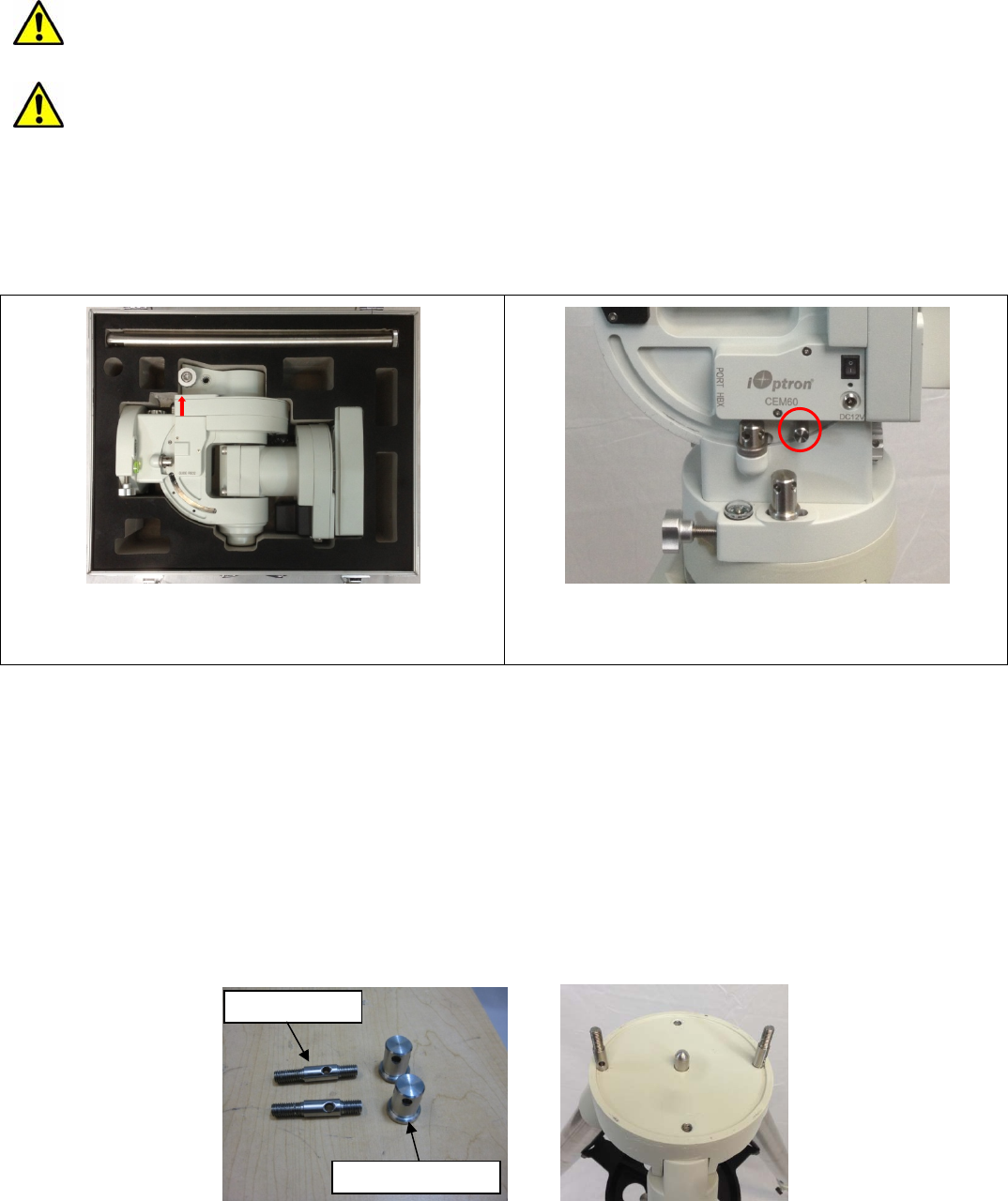
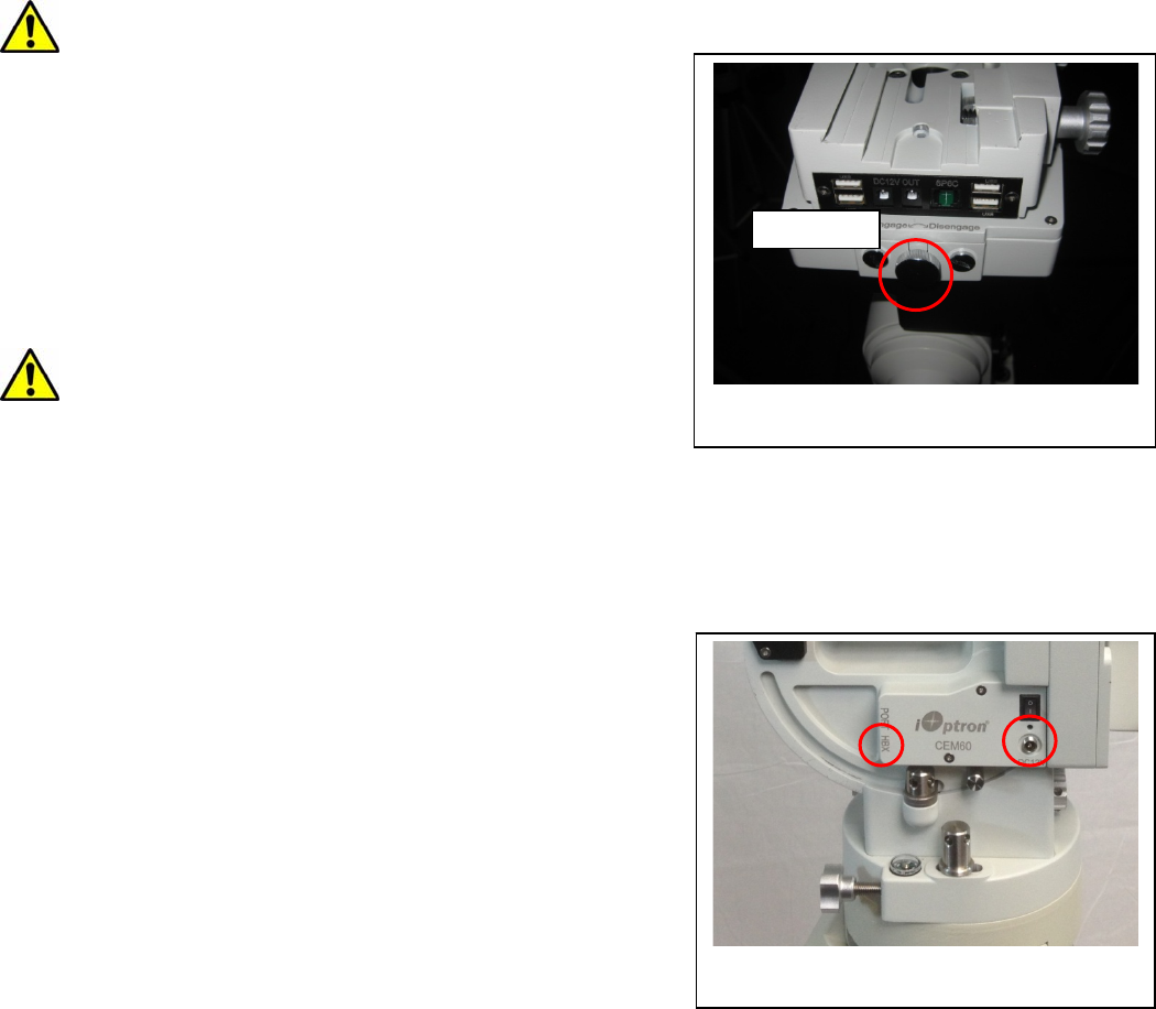
STEP 1. Removing the Mount from the Carrying Case
The mount is shipped with both R.A. Gear Switch disengaged. ALWAYS turn the Gear Switch fully
counterclockwise to fully engage the Gear Switch before removing the mount from the carrying case (Figure
11).
Figure 11. Engage the Gear Switches before
removing the mount from the carrying case
Figure 12. Stainless steel lever
The CEM60 mount comes with a stainless steel (SS) lever which can be unthreaded from the
mount. It can be used for tightening all the screws/nuts (Figure 12).
STEP 2. Attaching the Mount
The mount has a 150mm diameter base which can be mounted onto an optional iOptron 2” tripod or
pier. If you have your own tripod/pier, make sure it has two M8 threaded holes separated by 130mm, with a
Φ12mm X 15mm center stud.
There are two sets of mounting studs and azimuth locking nuts. Thread the two studs onto an
iOptron tripod/or pier (if you are using one). Use the pair of mounting holes that are closest to the edge and
thread the studs using the shorter thread side. Use the lever to tighten the mounting studs. Make sure that
two studs are aligned eastern-western side by turning the tripod or pier.
Figure 13. Mounting studs and locking nuts
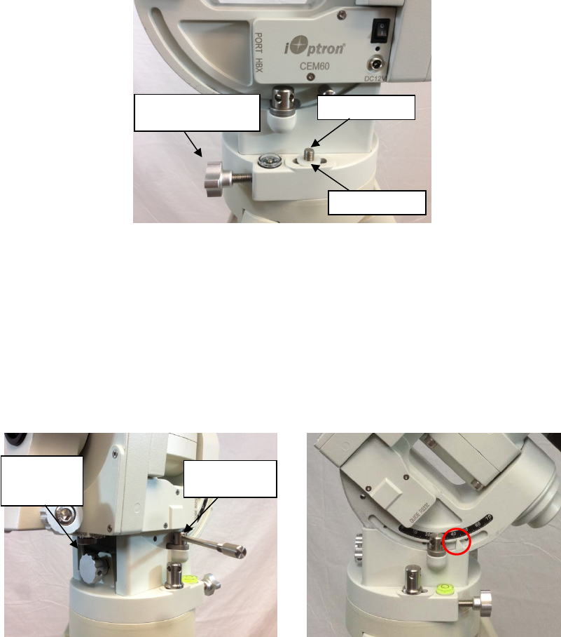
Back out the azimuth adjustment knobs to make enough room to prevent them from blocking the
mounting knobs. Put the mount head onto the tripod. Make sure that the mount head is facing north. Install
Mounting studs
Azimuth locking nuts
14
the Nylon washer. Put the azimuth locking nuts onto the mounting studs, hand tighten them. Adjust
tripod/pier to level the mount.
Figure 14. Attaching the mount
STEP 3. Setting the Latitude
This step requires you to know the latitude of your current location. This can be found from your
8407 hand controller after the embedded GPS receives the signal from the satellites. It also can be easily
found on the Internet, with your GPS navigator or a GPS capable cell phone. You will have to change this
latitude setting every time you significantly change your night sky viewing location. This setting directly
affects the mount’s GOTO accuracy.
Slightly loosen the Latitude Locking Clamps. Turn the Latitude Adjustment Knob until the arrow
points to your current latitude on the Latitude Scale. Tighten the Latitude Locking Clamps when done.
Figure 15. Setting the latitude
At this point, with the mount leveled and pointed north, and the latitude set, the Polar Axis (R.A. axis)
should be pointing very close to the NCP and Polaris. This alignment accuracy will be sufficient for visual
tracking and short duration piggy-back (camera mounted on top of the OTA) astrophotography.
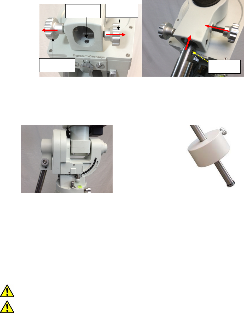
STEP 4. Installing the Counterweight (CW) Shaft
There are three screws on CEM60 CW Mounting Housing: A Shaft Locking Screw, a Shaft Position
Screw on the other side and a Low-Latitude Set Screw.
To install the CW shaft
(1) Remove CW Shaft Locking Screw from the CW Mounting Housing and back out the CW Shaft
Position Screw to make room for the CW shaft;
Latitude
locking clamp
Latitude
Adjustment
knob
Mounting stud
Azimuth adjustment
knob
Nylon washer
15
(2) Insert CW Shaft into the CW Mounting Housing. Make sure the rounded top of the shaft is fully
engaged in the slot;
(3) Insert the CW Shaft Locking Screw into the TOP hole and thread it onto the CW shaft;
(4) Tighten the CW Shaft Position Screw.
Figure 16. Install the counterweight shaft
At very low-latitudes (<10°), to avoid CW bumping into tripod leg, turn the rear Low Latitude Position
Screw (a hex head set screw) further into CW Mounting Housing before tightening the CW Shaft Positioning
Screw and Shaft Locking Screw.
DO NOT rock the counterweight shaft rigorously. It may damage the worm system.
Figure 17. Tilt the counterweight shaft for low
altitude
Figure 18. Install the counterweight
STEP 5. Installing the Counterweight(s)
Before installing the Counterweight, make sure that both R.A. and DEC Gear Switches are fully
engaged to avoid sudden mount movements, which could injure yourself or damage the mount gear
system.
Make sure the mount is at zero position (i.e. counterweight shaft is pointing to ground when the
counterweight is installed.)
Remove the CW Safety Cap at the end of CW Shaft. Guide the CW over the shaft. Tighten the CW
Locking Screw to hold the CW in place. Always place the Safety Cap back onto the shaft prior to use
to prevent personal injury and/or equipment damage.
WARNING: The mount should always be kept in the zero position while it is being loaded with
CWs and payload.
WARNING: The zero position is the only safe position the mount should stay in unless it is
balanced.
Shaft locking
screw
Shaft position
screw
Low latitude
position screw
Threads on
CW shaft
16
STEP 6.Balancing the Payload
After attaching the scope and accessories, the mount head assembly must be balanced in both the
R.A. and DEC axes to ensure minimum stress on the mount driving mechanism.
WARNING: The telescope may swing freely when the R.A. or DEC Gear Switch is
disengaged. Always hold on to the telescope assembly before releasing the Gear Switches
to prevent it from swinging, which can cause personal
injury and/or equipment damage.
The CEM gear system utilizes a magnetic force system
for optimal gear meshing. Fully turn the Gear Switch clockwise
to disengage the worm from the worm wheel. Turn the Gear
Switch counterclockwise to engage the worm to worm wheel,
as indicated on the mount. There is NO state between
Engaged and Disengaged. Setting the Gear Switch in
between states may damage the worm or worm wheel.
WARNING: The balancing process MUST be done
with Gear Switch at the Disengaged position!
Otherwise it might damage the worm system.
With the corresponding Gear Switch disengaged,
balance the assembly in R.A. axis by moving CW along its shaft. Balance in DEC axis by moving the scope
with accessories back and forth in the mount saddle or within the scope mounting rings.
Only balance one axis at a time and start with the DEC axis first. Double check the mount to make
sure both the R.A. and DEC axes are balanced.
Return the mount to the Zero Position after balancing; i.e., the CW Shaft points to ground, and the
telescope tip is at its highest position.
Set both Gear Switches to engaged positions after
balancing the mount. To make sure the gears are meshed
properly, gently turn the Gear Switch counterclockwise all
the way until you feel the resistance, but not over
tightening. You may back out 1//8 turn if the gear is not
moving smoothly.
STEP 7. Connecting Cables
Plug in a 12V DC power supply to the DC12V POWER
socket. Connect the Go2Nova® 8407 Hand Controller to the
HBX port on the mount side panel.
STEP 8. Setting Hand Controller
The CEM60 mount is equipped with a GPS receiver, which will receive the time, longitude and
latitude information from satellites after the link is established. However, there are still some parameters
which need to be entered to reflect your location, such as time zone info and daylight saving time. The
information will be stored inside the hand controller memory along with longitude and latitude coordinates
until they need to be changed.
A clear sky and open space outside is needed for the GPS to establish its link with the satellites. The
GPS is installed on the side of the mount with a black plastic cover. If it has difficulty to receive the GPS
signal, you may turn the mount head to the side of the mount to clear the space on top of it.
To set up the controller, press MENU =>“Settings”:
Figure 19. Gear switches
Gear switch
Figure 20. Connecting the cables
17
Press ENTER and select “Set Time & Site”
Press ENTER. A time and site information screen will be displayed:
Set Local Time
The time will be updated automatically when the GPS receiver has established its link with the GPS
satellites. You also can manually input the time information in case GPS does not function. Use the ◄ or ►
key to move the cursor _ and use the number keys to change the numbers. Use the ▲ or ▼ button to
toggle between “Y” and “N” for Daylight Saving Time. Hold the arrow key to fast forward or rewind the
cursor.
In order to make the Hand Controller reflect your correct local time, time zone information has to
be entered. Press the ◄ or ► key, move the cursor to the third line “300 Min. behind UT” to set the time
zone information (add or subtract 60 minutes per time zone). Enter minutes “ahead of” or “behind” UT
(universal time). For Example,
Boston is 300 minutes “behind” UT
Los Angeles is 480 minutes “behind” UT
Rome is 60 minutes “ahead of” UT
Beijing is 480 minutes “ahead of” UT
Sydney is 600 minutes “ahead of” UT
All the time zones in North America are behind UT, as shown in the following table. So make sure it
shows “behind” instead of “ahead of” UT.
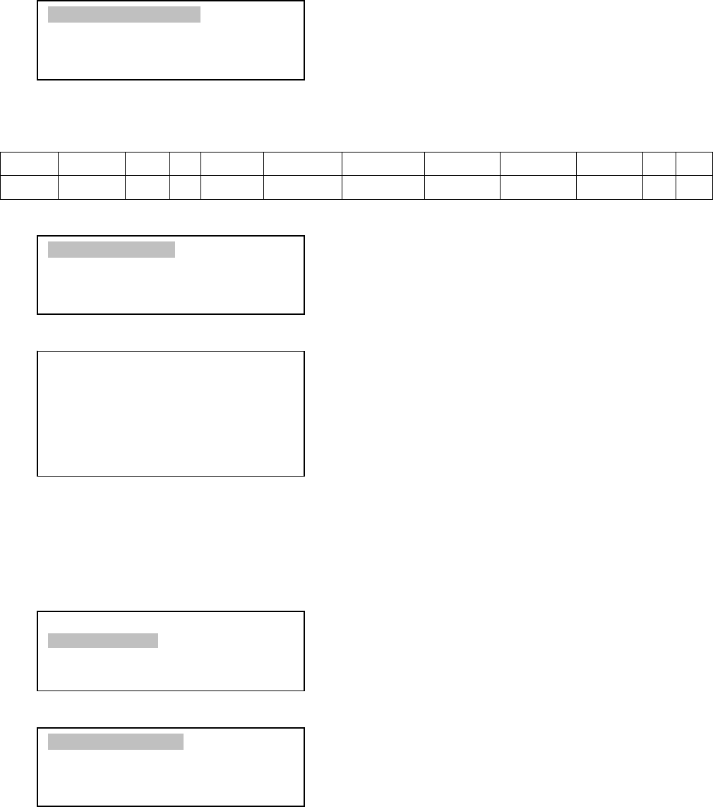
Time Zone Hawaii Alaska Pacific Mountain Central Eastern
Hour behind UT -10 -9 -8 -7 -6 -5
Enter Minutes 600 540 480 420 360 300
2014-03-09 10:19:18
Daylight Saving Time Y
300 Min. behind UT
Longitude:W071d08m50s
Latitude: N42d30m32s
Northern Hemisphere
Set Time & Site
Set Display and Beep
Set Guiding Rate
Set Tracking Rate
Set Parking Position
Meridian Treatment
Tracking Below Horizon
Set Eyepiece Light
Select and Slew
Sync. to Target
Alignment
Settings
Electric Focuser
PEC Options
Telescope Motion
Edit User Ob
j
ects

18
To adjust minutes, move the cursor to each digit and use the number keys to input number directly.
To change the “behind” or “ahead of” UT, move the cursor to “behind” and using the ▲ or ▼ key to toggle
between “behind” and “ahead of”. When the number is correct, press ENTER and go back to the previous
screen. Fraction time zone can be entered.
Do not manually add or subtract an hour from displayed time to reflect the DST. Only select “Y” after
DST begins.
For other parts of the world you can find your “time zone” information from iOptron website
(http://www.ioptron.com/support.cfm?module=faq#).
Set Observation Site Coordinates
The third and fourth lines display the longitude and latitude coordinates, respectively. The longitude
and latitude coordinates will be automatically updated when the GPS picks up satellite signals. “W/E”
means western/eastern hemisphere; “N/S” means northern/southern hemisphere; “d” means degree; “m”
means minute; and “s” means second.
If, for any reason, your GPS does not pick up the signal, you can manually enter the GPS
coordinates. Press the ◄ or ► key to move the cursor and using the ▲ or ▼ key to toggle between “W”
and “E”, “N” and “S”, and using the number key to change the numbers. It is always a good idea to do your
home work to get the GPS coordinates before traveling to a new observation site.
The site coordinates information can be found from your smart phone, GPS receiver or internet. In
case you only find the site information in decimal format you can convert them into d:m:s format by
multiplying the decimal numbers by 60. For example, N47.53 can be changed to N47º31'48”: 47.53º = 47º
+0.53º, 0.53º=0.53x60'=31.8', 0.8'=0.8x60"=48". Therefore, 47.53º=47º31'48" or 47d31m48s.
Select N/S Hemisphere
If the polar axis is aligned to the North Celestial Pole, then set the mount to Northern Hemisphere. If
the polar axis is pointing to the South Celestial Pole, set the mount to Southern Hemisphere. Press the ◄ or
► key to move the cursor and using the ▲ or ▼ key to toggle between “Northern Hemisphere” and
“Southern Hemisphere”.
As an example, select Northern Hemisphere if you are located in US and press ENTER to go back
to the main menu.
The time and site information will be stored inside the HC memory chip. If you are not traveling to
another observation site, they do not need to be changed.
The hand controller has a real time clock. Every time the mount is turned on, it should display the
correct time after initial set up. If the time is off too much, please check the clock battery inside the hand
controller and replace it if required. The battery is a 3V, CR1220 button battery.
STEP 9. Performing Polar Alignment
One of the CEM60’s unique features is that the polar scope can be accessed at anytime. It will not
be blocked by DEC axle as in a German equatorial mount. This makes it possible to adjust the polar
alignment during the tracking.
In order for an equatorial mount to track properly, it has to be accurately polar aligned.
19
Figure 21. Polar alignment
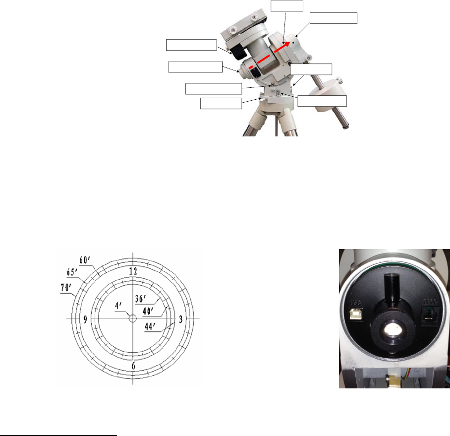
As indicated in Figure 22, the Polar Scope Dial has been divided into 12 hours along the angular
direction with half-hour tics. There are 2 groups, 6 concentric circles marked from 36’ to 44’ and 60’ to 70’,
respectively. The 36’ to 44’ concentric circles are used for polar alignment in the northern hemisphere using
Polaris. While the 60’ to 70’ circles are used for polar alignment in southern hemisphere using Sigma
Octantis.
Figure 22. Polar Scope
Figure 23. Polar Scope LED
Quick Polar Alignment
(1) Level the CEM60 mount and set it at Zero Position. Make sure the telescope is parallel to the pole
axis (R.A. axis) of the mount. If a finder scope is used, adjust it to be parallel to the telescope
optical axis. Remove both the Polar Axis Cover and Polar Scope Cover.
(2) Connect the polar scope illumination LED (Figure 23) to the Reticle socket located next to DEC
motor unit (Figure 3). Turn the mount power on. Use the Hand Controller (“Settings” => “Set
Eyepiece Light”) to set the illumination intensity.
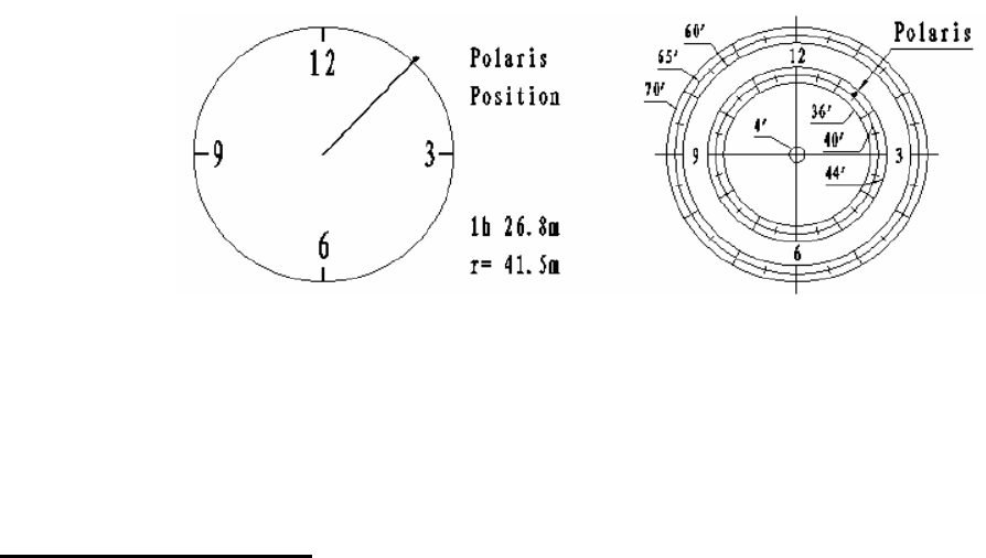
(3) Use the Hand Controller (MENU => “Align” => “Pole Star Position”) to display the Polaris
Position on the LCD screen, as indicated in the left side of the figure below. For example, on May
30, 2010, 20:00:00 in Boston, United States (Lat N42º30’32” and Long W71º08’50”, 300 min
behind UT, DST set to Y), the Polaris Position is 1hr 26.8m and r = 41.5m.
(4) Look through the polar scope to find the Polaris. Use the Azimuth and Latitude Adjustment Knobs
to adjust the mount in both directions and put the Polaris in the same position on the Polar Scope
Dial as indicated on the HC LCD. In this case, the Polaris will be located at a radius of 41.5’ and
an angle of 1 hour 26.8 minute, as shown In Figure 24 (b).
DECdriveunit
Polaraxiscover
Polarscopecover
Az.adj.knobAz.Lockingnut
Lat.lockingclamp
Polaraxis
Lat.adj.knob
20
(a) (b)
Figure 24. Polaris Position shown on HC (a) and where to put on polar scope dial (b)
NOTE: If you are located in the southern hemisphere, Sigma Octantis will be chosen for Polar
Alignment. For example, on May 20, 2010, 20:00:00 in Sydney, Australia (LatS33º51’36” and Long
E151º12’40”), 600 min ahead of UT, the Sigma Octantis Position is 1hr21.8m and 64.4m.
BrightStar Polar Alignment
When the pole star is not in sight:
(1) Level the mount and set it at Zero Position. Align the telescope to the R.A. axis of the mount. If a
finder scope is used, adjust it to be parallel to the telescope optical axis.
(2) Use the HC (MENU => “Align” => “Polar Align”) to display the azimuth and altitude position of
several bright stars near the meridian. Select one that is visible with high altitude as the
Alignment Star A. Follow the HC instruction to move the Star A to the center of the eyepiece with
the combination of using the Latitude Adjustment Knob and the “◄” or “►” button. Press ENTER
to confirm the centering. Next, select a bright star that is close to the horizon as the Alignment
Star B. Center it using the Azimuth Adjustment Knob and the “◄” or “►” button (The “▲” and
“▼” buttons are not used here). Press ENTER to confirm the settings.
(3) The telescope will now slew back to Star A to repeat the above steps. The iteration can be
stopped when it is determined that the alignment error has been minimized. Press the BACK
button to exit the alignment procedure.
NOTE: It is highly recommended to use an eyepiece with illuminated crosshair for accurate
centering.
NOTE: The movement of the alignment star in your eyepiece may not be perpendicular but crossed,
depends on its location in the sky.
STEP 10. Returning Mount to Zero Position
After polar alignment and balancing OTA, return the mount to Zero Position, as shown in Figure 25.
The Zero Position is the position with the CW shaft pointing towards the ground, OTA/Dovetail is at the
highest position with its axis parallel to the polar axis and the OTA pointing to the CP. Loosen the DEC and
R.A. Gear Switches to adjust the mount to the Zero Position. Engage the clutches after each adjustment.
Remember, the hand controller needs to be at the Zero Position as well! The simplest way is turn the
mount power OFF and ON again to reset the hand controller. Alternatively you can use the hand controller
(MENU => “Goto Zero Position”) to set the mount to the Zero Position.
21
Figure 25. Zero position
22
4. Getting Started
In order to experience the full GOTO capability of GOTONOVA® technology it is very important to set
up the mount correctly before observation.
4.1. Setting the Mount and Performing Polar Alignment
Assemble your CEM60 mount according to Section 3.2. Make sure the mount is leveled. Turn the
mount power switch on. When the GPS receiver is connected to satellites, the hand controller LCD will
display GPS OK. The mount will have correct time and site information. You can also enter them manually
as described before. Mount an OTA and accessories, and carefully balance the mount on both R.A. and
DEC axes. Polar align the mount using either the Quick Polar Alignment or BrightStar Polar Alignment
Procedure.
When the mount is powered on, the default position for the mount should be the Zero Position, i.e.
the counterweight shaft is pointing to ground, telescope is at the highest position with its axis parallel to the
polar axis and the telescope is pointing to the North Celestial Pole, if you are located in northern
hemisphere. If the mount is not at the zero position, release the gear switches to adjust the mount to
approximately the zero position.
The exception for a mount to be not at the Zero Position is when the mount is switched on after it
was parked before powering off (MENU => “Telescope Motion” => “Park Scope” )
4.2. Manual Operation of the Mount
The mount can now be used to observe astronomical objects with the HC. Use arrow keys (►, ◄,
▼, and ▲) to point the telescope to the desired object. Use the number keys to change the slewing speed.
Press the STOP/0 button to start tracking.
4.3. One Star Alignment
Make sure the mount is at the ZERO position by pressing MENU => “Goto Zero Position”. Release
R.A. and DEC gear switches to manually adjust the mount to the zero position. Perform a “One Star Align”
to correct the Zero Position discrepancy.
To perform “One Star Align,” press MENU button, scroll down to “Align”, select “One Star Align”
and press ENTER. The hand controller will display a list of bright objects for you to select from. Select an
object using ▲ or ▼ key. Then press ENTER. After the mount slews to the target, use the arrow keys to
center it in your eyepiece. Then press ENTER. (More align details in 5.4)
4.4. Go to the Moon and Other Stars
Now the mount is ready for GOTO and tracking targets. One of the most common objects is the
Moon.
Press MENU, select and ENTER “Select and Slew”. Select a category (for example, “Solar
System”), then select an object of interest (for example, “Moon”). Press ENTER and the telescope will
slew to the object and automatically start tracking. If the target is not centered in your eyepiece, use the
arrow keys to center it. Then use MENU => “Sync to Target” for better performance.
23
4.5. Star Identification Function
The 8407 hand controller has a star identification function. After Polar Alignment and Set Time &
Site, slew the telescope to a bright star manually or using the GOTO function. Press ? (Help) button to
identify the star that the telescope is pointing to, as well as nearby bright stars if there are any.
4.6. Turning Off the Mount
When you have finished your observation, just simply turn the mount power off and disassemble the
mount and tripod.
If the mount is set up on a pier or inside an observatory, it is recommended that you return the
mount to Zero Position or park the telescope. This will ensure that there is no need for you to perform the
initial setup again when you power on the mount subsequently with the mount not moved from the parked
position.
4.7. Putting the Mount Back into the Carrying Case
Make sure that the Gear Switches are fully engaged before removing the mount from the tripod. Lay
the mount into the carrying case. Turn the R.A. Gear Switch clockwise all the way in to disengage the
gear system for transportation.

24
5. Complete Functions of Go2Nova® 8407Hand Controller
5.1. Select and Slew
Press the MENU button. From the main menu select “Select and Slew.” Select an object that you
would like to observe and press the ENTER key.
The Go2Nova® 8407 hand controller has a database of about 358,000 objects. Use the ► or ◄
buttons to move the cursor. Use the number buttons to enter the number, or the ▼ or ▲ buttons to change
the individual number. Hold on a button to fast scroll through the list. The “ ” indicates the object is above
the horizon, and a “ ” means it is below the horizon. In some catalogs those stars below the horizon will
not be displayed on the hand controller.
5.1.1. Solar System
There are 9 objects in the Solar system catalog.
5.1.2. Deep Sky Objects
This menu includes objects outside our Solar system such as galaxies, star clusters, quasars, and
nebulae.
Named Objects: consists of 60 deep sky objects with their common names. A list of named deep
sky objects is included in Appendix E.
Messier Catalog: consists of all 110 Messier objects.
NGC IC Catalog: consists of 7,840 objects in the NGC catalog and 5,386 objects in the IC
catalog. To select an object from the NGC or IC catalog, move the cursor to NGC, using▲ or ▼
button to toggle between NGC and IC. Then move the cursor to a numerical position and use the
number button to select the object.
UGC Catalog: consists of 12,921 objects.
MCG Catalog: consists of 30,642 objects.
Caldwell Catalog: consists of 109 objects.
Abell Catalog: consists of 4,076 objects.
Herschel Catalog: consists of 400 objects.
5.1.3. Stars
Named Stars: consists of 195 stars with their common names. They are listed alphabetically. A
list is included in Appendix E.
Binary Stars: consists of 210binary stars. A list is attached in Appendix E.
GCVS: consists of 38,528 variable stars in the catalog.
SAO Catalog: consists of 258,997SAO catalog objects. They are listed numerically.
5.1.4. Comets
This catalog contains 15 comets.
5.1.5. Asteroids
This catalog contains 116 asteroids.
25
5.1.6. Constellations
This catalog consists of 88 modern constellations. They are listed alphabetically. A list is attached in
Appendix E.
5.1.7. Custom Objects
It can store up to 60 user-defined objects, including comets.
5.1.8. Enter R.A. DEC
Here you can go to a target by entering its R.A. and DEC numbers.
5.2. Sync to Target
This operation will match the telescope's current coordinates to Target Right Ascension and
Declination. It can be used to correct GOTO pointing error. After slewing to an object, press MENU - then
scroll to “Sync to Target” and press ENTER. Follow the screen to do the sync. Using this function will re-
align the telescope to the selected object. Multiple syncs can be performed if needed. This operation is most
useful to find a faint star or nebula near a bright star.
“Sync to Target” will only work after “Select and Slew” is performed. You can change the moving
speed to make the centering procedure easier. Simply press a number (1 through 9) key to change the
speed. The default moving speed is 64X.
“Sync to Target” is similar to “One Star Align”, except that you choose the object to “sync” to. “One
Star Align” chooses the star/object for you.
5.3. Align
This function is used for aligning the telescope. The hand controller provides two polar alignment
methods. “Polar Align” uses a set of 2 bright stars for polar alignment. This provides a viable polar
alignment approach for those who can’t see the polar. The “Two Star Polar Align” is used to refine the
polar alignment using the AccuAlignTM polar scope. The system also provides three star alignment methods:
“SolarSys Align”, “One Star Align”, and “Multi-Star Align”. The mount has to be at Zero Position before
performing any star alignment.
5.3.1. Pole Star Position
This function displays the position of the Pole Star for Quick Polar Alignment using iOptron
®
AccuAlignTM polar scope. The position of Polaris is displayed in northern hemisphere or Sigma Octantis in
southern hemisphere.
5.3.2. Polar Align
This BrightStar Polar Alignment allows you do a polar alignment without seeing the Pole Star.
Press the MENU button, then select “Align” and “Polar Align”. The HC will display a list of bright alignment
stars near the meridian, with name, magnitude, azimuth and altitude position. Select one that is visible and
high in altitude as the Alignment Star A. Follow the HC instruction to move the Star A to the center of the
eyepiece with the combination of using Latitude Adjustment Knob and “◄” or “►” button. Press ENTER to
confirm the settings. Next, select a bright star that is close to the horizon as the Alignment Star B. Center it
using the Azimuth Adjustment Knob and “◄” or “►” button (The “
▲”
and “
▼”
buttons are not used here).
Press ENTER to confirm the settings.
26
The telescope will now slew back to Star A to repeat the above steps. The iteration can be stopped
when it is determined that the alignment error has been minimized. Press BACK button to exit the
alignment procedure.
NOTE: It is highly recommended to use an eyepiece with illuminated crosshairs for accurate centering.
NOTE: The movement of the alignment star in your eyepiece may not be perpendicular but crossed,
depends on its location in the sky.
5.3.3. One Star Alignment
Press MENU button and select “Align”. Select “One Star Align” and press ENTER. A list of
alignment stars that are above the horizon is computed based on your local time and location. With the
mount at the “Zero Position,” use ▲ and ▼ buttons to select a star and press ENTER. Center the target in
your eyepiece using arrow key. Press ENTER when finished. If your mount is set up correctly and polar
aligned, one star alignment should be sufficient for good GOTO accuracy. To increase the average pointing
accuracy over the sky, you may choose to do multi-star alignment.
5.3.4. Solar System Align
This function uses a planet or the moon as an alignment object. Press MENU button and select
“Align”. Select “Solar System Align” and press ENTER for available alignment object.
5.3.5. Multi-Star Align
With iOptron’s multi-star alignment, you can choose two, three, or as many stars as you want to
reduce the mount average pointing offset across the sky. First, make sure you perform the “One Star Align”
procedure.
Press MENU button and select “Align”. Select “Multi-Star Align” in the align menu. A list of
alignment stars that are above the horizon is computed based on your local time and location. With the
mount is at the “Zero Position,” use ▲ and ▼ buttons to select first alignment star and press ENTER.
Center the target in your eyepiece using the arrow keys. Press ENTER when finished. The hand controller
will prompt you to choose the second star. If the star you choose is too close to the first one, the system will
let you choose another one. When the mount is aligned with the second star, the two star alignment is
finished. You can reject the suggested star if it is blocked by a tree or other obstruction.
When you are done with the two star alignment, press the BACK button to finish the alignment.
Press ENTER key to select third star for further alignment.
5.3.6. Two Star Polar Align
This Two Star Polar Align may improve the polar alignment accuracy. It requires a wider view of
the sky, since the two alignment stars need to be far apart. Press MENU button and select “Align”. Select
“Two Star Polar Align” in the align menu. A list of alignment stars that are above the horizon is computed
based on your local time and location. With the mount at the “Zero Position,” use the ▲ and ▼ buttons to
select first alignment star and press ENTER. Center the target in your eyepiece using the arrow keys after
the mount slews to it. Press ENTER when finished. The hand controller will prompt you to choose the
second star. After centering the second star, the two-star alignment is finished. You can reject the
suggested star if it is blocked by a tree or other obstruction.
After the two-star alignment, a pointing error between the R.A. axis and the polar axis will be
recorded. This number can be used to fine tune the R.A. axis.
For example, if the screen shows 7.5" lower and 4.3" east, it means that THE MOUNT axis is
pointing lower and to the east.
5.3.7. Display Axes Error
This displays the pointing error between the R.A. axis and the polar axis.
27
5.4. Settings
5.4.1. Set Time & Site
Refer to STEP 8 in Section 3.2.
5.4.2. Set Beep
The Hand Controller allows a user to turn off the beep partially, or even go to the silent mode by
press “MENU =>Settings =>Set Beep”,
Select one of three available modes:
"Always On” – a beep will be heard on each button operation or mount movement;
“On but Keyboard” – a beep will be heard only when the mount slewing to the object or there is a
waning message; or
“Always Off” – all the sound will be turned off, including SUN wrning message.
5.4.3. Set Display
Press “MENU =>Settings =>Set Display”,
Use the arrow keys to adjust LCD display contrast, LCD backlight intensity and keypads backlight
Intensity.
5.4.4. Set Guider Rate
This is an advanced function for autoguiding when a guiding camera is equipped either via a Guide
Port or an ASCOM protocol. Before autoguiding, align the polar axis carefully. Select a proper guiding
speed. The suppositional guiding speed can be selected from ±0.10X to ±0.80X. Follow the autoguiding
software for detailed operation.
Figure 26. Guide port pinout
Set Up Time and Site
Set Beep
Set Display
Set Guiding Rate
Set Tracking Rate
Set Parking Position
Meridian Treatment
Tracking Below Horizon
Set Up Time and Site
Set Beep
Set Display
Set Guiding Rate
Set Tracking Rate
Set Parking Position
Meridian Treatment
Tracking Below Horizon

28
The guide port wiring is shown in Figure 26, which is same as that from Celestron / Starlight Xpress /
Orion Mount / Orion Autoguider/ QHY5 autoguider pinout.
If you have an autoguider that has a pinout similar to ST-i of SBIG, such as Meade/ Losmandy/
Takahashi/ Vixen, make sure a proper guiding cable is used. Refer to your guiding camera and guiding
software for detailed operation.
DO NOT plug your ST-4 guiding camera cable into any iOptron port or HBX port. It may damage the
mount or guiding camera electronics.
5.4.5. Set Tracking Rate
You can set up the mount tracking rate by selecting “Set Tracking Rate”. Then the user can select
“Sidereal speed”, “Lunar speed”, “Solar speed”, “King speed” and “User defined speed”. For “User
defined speed,” it can be adjusted from 0.9900X to 1.0100X of sidereal speed by pressing the ▲or ▼
button or the number buttons.
5.4.6. Set Parking Position
You may park the telescope before powering off the mount. This is very useful if the mount is on a
permanent pier or the mount will not be moved in between observation sessions. The mount will keep all the
alignment info and reference points.
There are four parking positions. “Default Horizon Pos.” will park the scope horizontally on the right
side of the mount. “Default Zenith Pos.” will park the scope vertically on the right side of the mount.
“Current Position” will park the scope at its current position. Or you can enter any altitude and azimuth
combination for “Custom Parking Pos.” When the mount is turned on, it will use last time parking position
setting as the default setting.
5.4.7. Meridian Treatment
This function tells the mount what to do when it tracks past the meridian. There are two options.
Telescope Flip will flip the telescope and continuously track the object. Stop Tracking Pos. will stop the
mount when it passes the meridian. You can define how far the mount will track pass the meridian before it
stops. The maximum traveling distance is 15°passing meridian, which equals to 1 hour.
5.4.8. Track Below Horizon
This function allows the mount to keep tracking an object even it is below the horizon but still can be
seen from an elevated observation site, such as on a hill. The power on default is at OFF state. One can
turn it on when needed.
5.4.9. Set Eyepiece Light
Use this function to adjust the light intensity of a CEM60 illuminated polar scope. If you have an
illuminated-reticule eyepiece and has the same socket size, you may use this option to adjust its light
intensity.
5.4.10. Heating Controller
Turn on/off the controller LCD back heater. When select ON for “Heating Controller”, the heater
would automatically be turned on when the ambient temperature reached 0°C (32°F) and shut off at 10°C.
5.5. Electric Focuser
This function controls iOptron electric focuser.
29
5.6. PEC Option
This function only works for a non-high precision encoder version of CEM60 mount.
5.6.1. PEC Playback
You can turn “PEC Playback On” while you do the tracking, especially for long time astro-
photography. The default status is “PEC Playback Off when the mount is turned on.
5.6.2. Record PEC
All equatorial mounts have a small variation in the worm gears which can be corrected by using
Period Error Correction or PEC. PEC is a system which improves the tracking accuracy of the mount by
compensating for variations in the worm gear and is especially useful when doing astrophotography without
autoguiding. Because the variations are regular, it is possible to record the corrections required to cancel
out the worm gear variations and to play them back to correct the periodic error caused by the variations.
In order to use the PEC function, the Go2Nova hand controller needs to record the PE first. The
periodic error of the worm gear drive will be used to correct periodic error. The data will be lost when the
power is turned off.
Here’s how to use the PEC function.
1. Setup the mount with a telescope in autoguiding condition by connecting a guiding camera to a
computer via mount’s Guide Port or ASCOM protocol;
2. Select “MENU=>Settings => Set Guiding Rates.” Set a guiding speed from 0.10X to 0.80X. The
default number is 0.25X;
3. Then press the BACK button and select “PEC Option” from the menu. Use the ▲ and ▼ scroll
buttons to display the “Record PEC” option and press ENTER to start record the PE.
4. It takes the worm gear 300 seconds to make one complete revolution. After 300 seconds PEC will
automatically stop recording. The PEC value will be permanently stored inside PEC chip on R.A. motor
drive until a new data are recorded.
5. If you want to re-record the periodic error, select “Record PEC” and repeat the recording
processes again. The previously recorded information will be replaced with the current information.
5.7. Telescope Motion
5.7.1. Park Scope
This function parks the scope to a preset position.
5.7.2. Search Zero Pos.
In the event of power failure, the mount will lose all its alignment info. It will be very troublesome for
a remote observation site where the mount might be controlled via internet. The CEM60 has been equipped
with a function that can find the zero position for an initial mount set up.
Select “Search Zero Pos.,” the mount will starting slew slowly and find the R.A. and DEC position to
set the mount to zero position. Do a “One Star Align” to correct any zero position discrepancy.
NOTE: This function is not intended for daily zero position setup.
30
5.8. Edit User Objects
Besides various star lists available in the hand controller -- you can add, edit or delete your own
user-defined objects, especially newly found comets. You can also add your favorite observation object into
the user object list for easy sky surfing. Up to 60 comets and other user objects can be stored.
5.8.1. Enter a New Comet
Press “MENU =>Edit User Objects” to set user objects.
Select “User Defined Comet” to add/browse/delete the user-defined comet list. Find the orbit
parameters of a comet in the SkyMap format. For example, the C/2012 ISON has an orbit parameter:
No. Name Year M Day q e ω Ω i H G
C/2012 S1 ISON 2013 11 28.7960 0.0125050 1.0000030 345.5088 295.7379 61.8570 6.0 4.0
Select “Add a New Comet” to add a new one:
The hand controller will display the parameter entry screen:
Enter the parameter using the arrow button and number keys. Press ENTER. A confirmation screen
will show. Press ENTER again to confirm storing your object under assigned user object number, or press
BACK button to cancel it.
5.8.2. Enter Other Objects or Observation List
Press “MENU =>Edit User Objects” to set user objects.
Select “Other Objects” to enter you own object:
Add a New Record
Browse Records
Delete One Record
Delete All Records
User Defined Comet
Other Objects
Enter Comet Parameter
Date: 0000-00-00.0000
q: 0.000000
e: 0.000000
ω: 000.0000
Ω: 000.0000
i: 000.0000
Add a New Comet
Browse Comets
Delete a Comet
Delete All Comets
User Defined Comet
Other Objects

31
Select “Add a New Record”. A screen will display asking to Enter R.A. and DEC:
You may enter the R.A. and DEC coordinates of the star you want to watch, and press ENTER to
confirm.
A more useful application of this function is to store your favorite viewing objects before heading to
the field. When the “Enter R.A. and DEC” screen appears, press the MENU button. It brings up the star
catalogs that you can select the star from. Follow the screen to add your favorite objects. Press BACK
button to go back one level.
Press the BACK button few times to go back to object entry submenu. You may review the records
or delete the one you don’t want it anymore. Press BACK button to finish the operation. Now you can slew
to your favorite stars from “Custom Objects” catalog using “Select and Slew.”
5.9. Firmware Information
This option will display firmware version information of Main board, R.A. board, DEC board and hand
controller.
5.10. Goto Zero Position
This moves your telescope to its Zero Position. When the power is turned on, the mount assumes
the Zero Position. This is the reference point for alignment and GOTO functions.
Enter R.A. and DEC
R.A.: 00h00m00s
DEC: +00d00m00s
32
6. Maintenance and Servicing
6.1. Maintenance
The CEM60 mount is designed to be maintenance free. Do not overload the mount. Do not drop the
mount, this will damage the mount or degrade the GOTO tracking accuracy permanently. Use a wet cloth to
clean the mount and hand controller. Do not use solvent.
If your mount is not to be used for an extended period, dismount the OTAs and counterweight(s).
6.2. iOptron Customer Service
If you have any question concerning your CEM60 mount contact iOptron Customer Service
Department. Customer Service hours are from 9:00 AM to 5:00 PM, Eastern Time, Monday through Friday.
In the event that the CEM60 requires factory servicing or repairing, write or call iOptron Customer Service
Department first to receive a RMA# before returning the mount to the factory. Please provide details as to
the nature of the problem as well as your name, address, e-mail address, purchase info and daytime
telephone number. We have found that most problems can be resolved by e-mails or telephone calls. So
please contact iOptron first to avoid returning the mount for repair.
It is strongly suggested that to send technical questions to support@ioptron.com. Call in the U.S.
1.781.569.0200.
6.3. Product End of Life Disposal Instructions
This electronic product is subject to disposal and recycling regulations that vary by country
and region. It is your responsibility to recycle your electronic equipment per your local
environmental laws and regulations to ensure that it will be recycled in a manner that protects
human health and the environment. To find out where you can drop off your waste equipment
for recycling, please contact your local waste recycle/disposal service or the product
representative.
6.4. Battery Replacement and Disposal Instructions
Battery Disposal- Batteries contain chemicals that, if released, may affect the environment
and human health. Batteries should be collected separately for recycling, and recycled at a
local hazardous material disposal location adhering to your country and local government
regulations. To find out where you can drop off your waste battery for recycling, please
contact your local waste disposal service or the product representative.

33
Appendix A. Technical Specifications
MountCenter‐balancedEquatorialMount(CEM)
Payload60lb(27.2kg),excludecounterweight
Mountweight27lb(12.3kg)
Payload/Mountweightratio2.22:1
MaterialAllmetal(except GPScover)
Latitudeadjustmentrange0
°
~70
°
Azimuthadjustmentrange±8
°
RightAscensionwormwheel
Φ
146mm,288toothaluminum
Declinationwormwheel
Φ
146mm,288teethaluminum
PECPPEC/RealtimePEC
PE~±5arcsecp‐p(#7200)or<0.5arcsecRMS(#7201)
Counterweightshaft
Φ
28x450mmStainlesssteel
Counterweight21lb(9.5 kg)
Mountbasesize
Φ
150mm
MotordriveSteppermotor
Resolution0.06 arcseconds
Slewspeed1×,2×,8×,16×,64×,128×,256×,512×,MAX(~3.75°/sec)
Powerconsumption0.6A(Tracking),1.1A(GOTO)
Powerrequirement12VDC2A
ACadapter100V~240V(included)
PolarScopeAccuAligningTM darkfieldilluminated,2arcmin
LevelindicatorLevelbubble
Dovetailsaddle8”Losmandy/Vixendualsaddle
HandControllerGo2Nova® 8407,359,000objectsdatabase,starrecognition
MeridiantreatmentStop(0‐15
°
pass),autoflip
GPSInternal32‐channelGPS
AutoguideportST‐4
CommunicationportSerialPort
PCcomputercontrolYes(ASCOM)
Cablemanagement4XUSB,2XDC12V(MAX5A),6P6C
Operationtemperature‐20
°
C~+45
°
C
TripodOptional2"tripodStainlessSteel(8kg)/Pier(10kg)
WarrantyTwoyearlimited
34
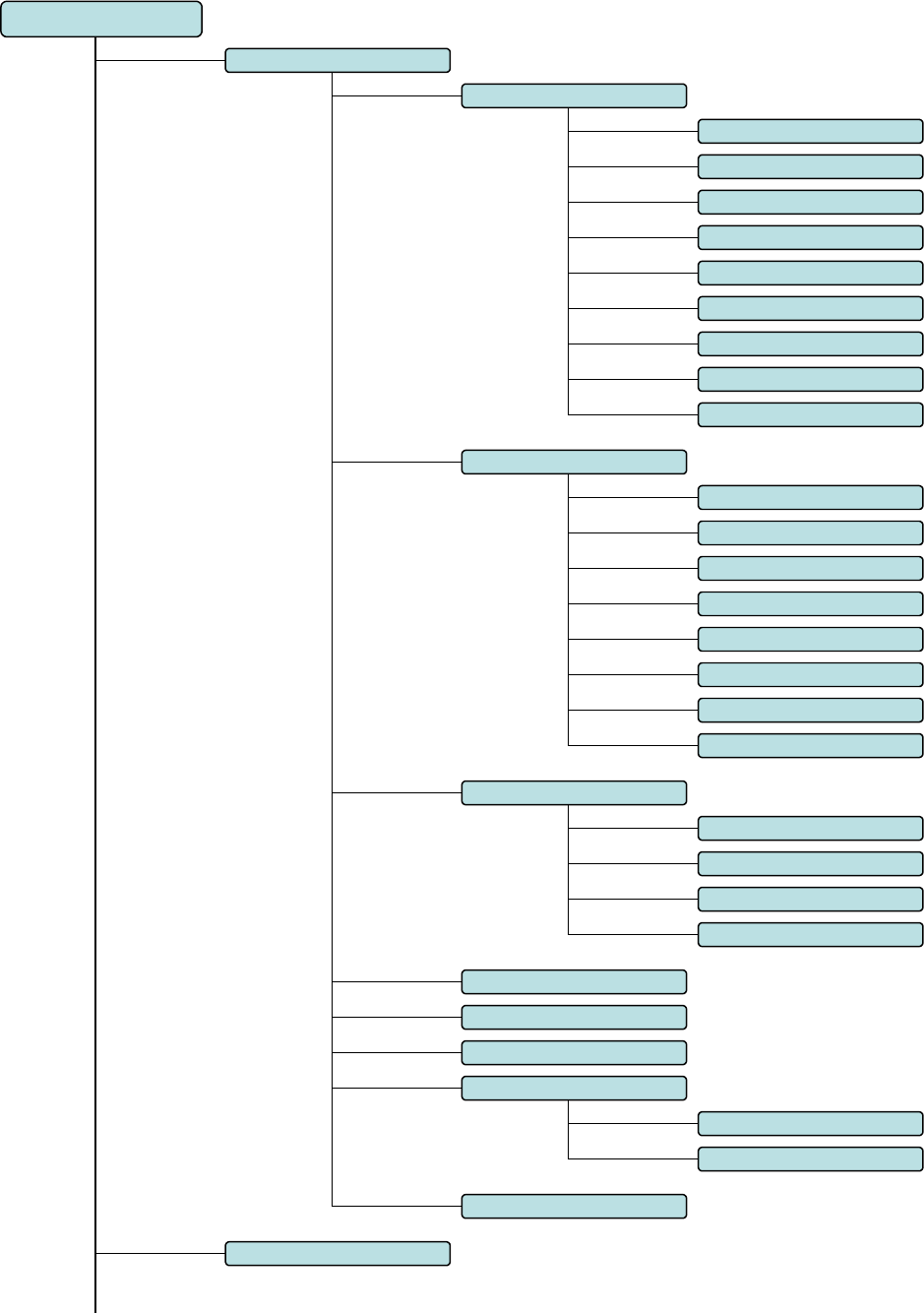
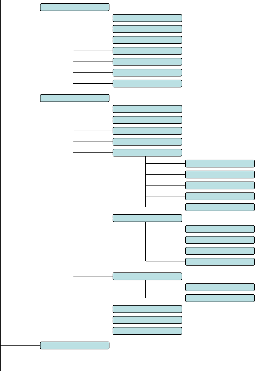
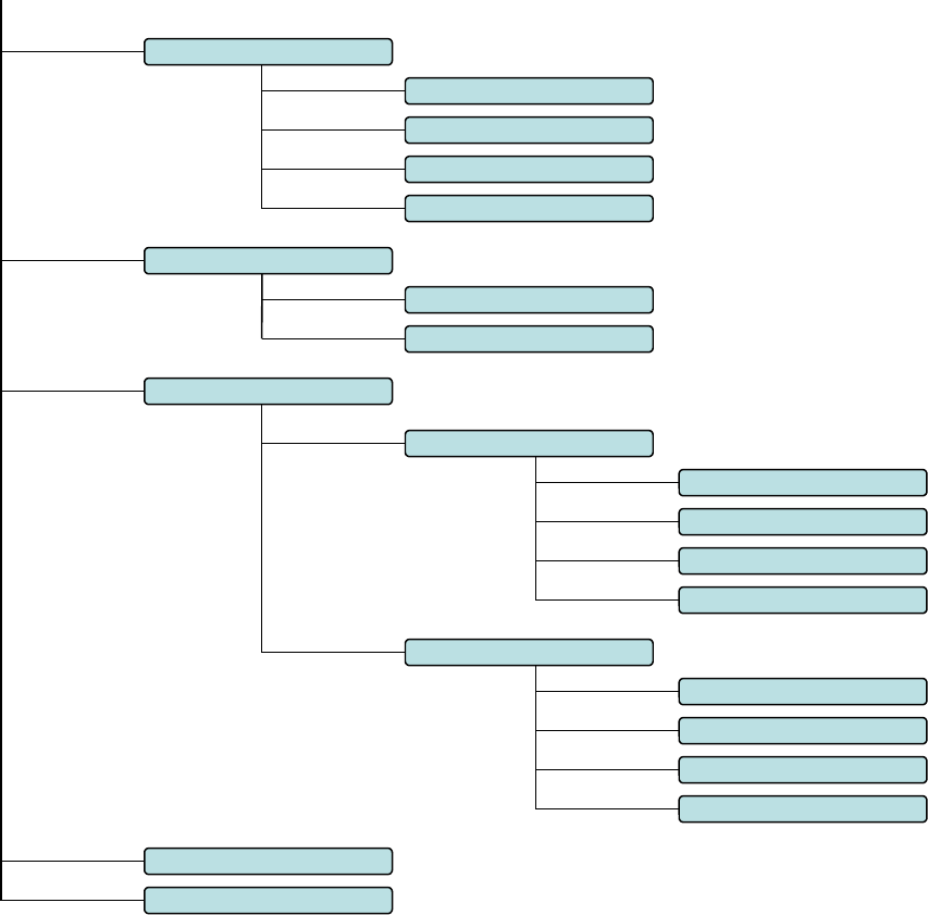
Appendix B. Go2Nova® 8407HC MENU STRUCTURE
MENU
Select and Slew
Solar System
Comets
Asteroids
Stars
Mercury
Venus
Mars
Jupiter
Saturn
Uranus
Neptune
Sun
Moon
Deep Sky Objects
Named Object
Messier Catalog
NGC IC
UGC
MCG
Caldwell Catalog
Abell Catalog
Herschel Catalog
Named Stars
Binary Stars
GCVS
SAO Catalog
Constellations
Custom Objects
Enter R.A. and DEC
Sync. To Target
Other Objects
User Def ined Comets
35
Settings
Set Time & Site
Set Display
Set Guiding Rate
Meridian Treatment
Set Eyepiece Light
Heating Controller
Alignment
One Star Align
Multi-Star Align
Two Star Polar Align
Pole Star Position
Set Tracking Rate
Sidereal Speed
Lunar Speed
Solar Speed
User Defined Speed
King Speed
Polar Align
Track Below Horizon
Set Parking Position
Def ault Horizon Pos.
Def ault Zenith Pos.
Stop Tracking Pos.
Meridian Flip
Solar System Align Align
Display Axes Error
Electric Focuser
Set Beep
Current Position.
Custom Park Pos.
36
Firmware Information
Goto Zero Position
Add a New Comet
Browse Comets
Delete a Comet
Clear All Comets
User Defined Comet
Set User Objects
Add a New Object
Browse Objects
Delete an Object
Clear All Objects
Other Objects
Telescope Motion
Park Scope
Search Zero Pos.
PEC Options
PEC Playback Off
Record PEC
PEC Playback On
PEC Data Integrity

37
Appendix C. Firmware Upgrade
The firmware in the 8407Hand Controller and control boards can be upgraded by the customer.
Please check iOptron’s website, www.iOptron.com, under Support Directory/CEM Mounts, select CEM60
for details.

38
Appendix D. Computer Control a CEM60 Mount
The CEM60 mount can be connected to a computer using supplied serial cable. A RS232 to USB
adapter (not supplied) is needed if your computer does not have a serial port, like most of the laptops on the
market today. Follow the adapter instructions to install the adapter driver.
When the communication between the mount and computer has been established, the mount can be
controlled via ASCOM protocol.
To control the mount via ASCOM protocol, you need:
1. Download and install ASCOM Platform from http://www.ascom-standards.org/. Make sure your
PC meets the software requirement. Refer to the ascom-standards website for details.
2. Download and install the latest iOptron Telescope .NET ASCOM drive from iOptron website.
3. Planetarium software that supports ASCOM protocol. Follow software instructions to select the
iOptron Telescope.
Please refer to iOptron website, www.iOptron.com, under Support Directory/ASCOM Driver, iOptron
Telescope .NET ASCOM Driver, for more detail.
CEM60 mount may also be directly controlled by other third party software and accessories. Please
contact them for more information.
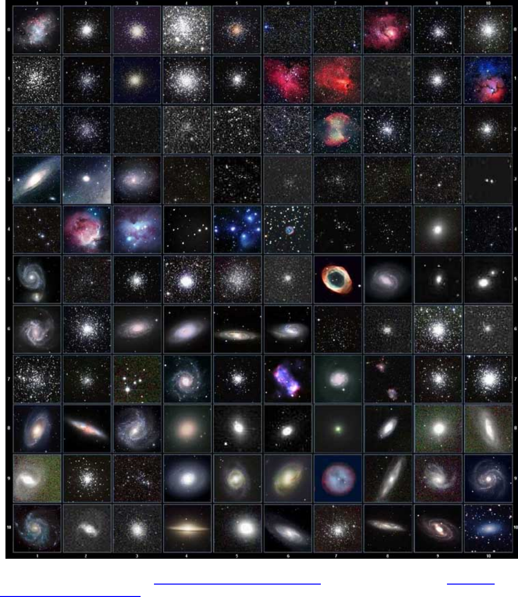
Appendix E. Go2Nova®Star List
Messier Catalog
This table is licensed under the GNU Free Documentation License. It uses material from the Wikipedia
article List of Messier objects

40
001 Acamar 050 Asellus Australis 099 Kaus Media 148 Rastaba
002 Achernar 051 Asellus Borealis 100 Keid 149 Regulus
003 Acrux 052 Aspidiske 101 Kitalpha 150 Rigel
004 Acubens 053 Atik 102 Kochab 151 Rigel Kentaurus
005 Adhafera 054 Atlas 103 Kornephoros 152 Ruchbah
006 Adhara 055 Atria 104 Kurhah 153 Rukbat
007 Al Na’ir 056 Avoir 105 Lesath 154 Sabik
008 Albali 057 Azha 106 Maia 155 Sadachbia
009 Alberio 058 Baten Kaitos 107 Marfik 156 Sadalbari
010 Alchibar 059 Beid 108 Markab 157 Sadalmelik
011 Alcor 060 Bellatrix 109 Matar 158 Sadalsuud
012 Alcyone 061 Betelgeuse 110 Mebsuta 159 Sadr
013 Aldebaran 062 Biham 111 Megrez 160 Saiph
014 Alderamin 063 Canopus 112 Meissa 161 Scheat
015 Alfirk 064 Capella 113 Mekbuda 162 Schedar
016 Algedi 065 Caph 114 Menkalinan 163 Seginus
017 Algenib 066 Castor 115 Menkar 164 Shaula
018 Algiebra 067 Celabrai 116 Menkent 165 Sheiak
019 Algol 068 Celaeno 117 Menkib 166 Sheratan
020 Algorab 069 Chara 118 Merak 167 Sirius
021 Alhena 070 Chertan 119 Merope 168 Skat
022 Alioth 071 Cor Caroli 120 Mesartim 169 Spica
023 Alkaid 072 Cursa 121 Miaplacidus 170 Sterope
024 Alkalurops 073 Dabih 122 Mintaka 171 Sulafat
025 Alkes 074 Deneb 123 Mira 172 Syrma
026 Almach 075 Deneb Algedi 124 Mirach 173 Talitha
027 Alnasl 076 Deneb Kaitos 125 Mirfak 174 Tania Australis
028 Alnilam 077 Denebola 126 Mirzam 175 Tania Borealis
029 Alnitak 078 Dubhe 127 Mizar 176 Tarazed
030 Alphard 079 Edasich 128 Muphrid 177 Taygeta
031 Alphecca 080 Electra 129 Muscida 178 Thuban
032 Alpheratz 081 Elnath 130 Nashira 179 Unukalhai
033 Alrakis 082 Eltanin 131 Nekkar 180 Vega
034 Alrescha 083 Enif 132 Nihal 181 Vindemiatrix
035 Alshain 084 Errai 133 Nunki 182 Wasat
036 Altair 085 Fomalhaut 134 Nusakan 183 Wazn
037 Altais 086 Furud 135 Peacock 184 Yed Posterior
038 Alterf 087 Gacrux 136 Phact 185 Yed Prior
039 Aludra 088 Giausar 137 Phecda 186 Zaniah
040 Alula Australis 089 Gienah 138 Pherkad 187 Zaurak
041 Alula Borealis 090 Gomeisa 139 Pleione 188 Zavijava
042 Alya 091 Graffias 140 Polaris 189 Zosma
043 Ancha 092 Groombridge 1830 141 Pollux 190 Zubenelgenubi
044 Ankaa 093 Grumium 142 Porrima 191 Zubeneschamali
045 Antares 094 Hamal 143 Procyon 192 Barnard's Star
046 Arcturus 095 Homan 144 Propus 193 Kapteyn's Star
047 Arkab 096 Izar 145 Rassalas 194 Kruger 60
048 Arneb 097 Kaus Australis 146 Rasagethi 195 Luyten's Star
049 Ascella 098 Kaus Borealis 147 Rasalhague
Named Star List

No. Constellation Abbreviation No. Constellation Abbreviation
1
A
ndromeda
A
nd 45 Lacerta Lac
2
A
ntlia
A
nt 46 Leo Leo
3
A
pus
A
ps 47 Leo Minor LMi
4
A
quarius
A
qr 48 Lepus Lep
5
A
quila
A
ql 49 Libra Lib
6
A
ra
A
ra 50 Lupus Lup
7
A
ries
A
ri 51 Lynx Lyn
8
A
uriga
A
ur 52 Lyra Lyr
9Boötes Boo 53 Mensa Men
10 Caelum Cae 54 Microscopium Mic
11 Camelopardalis Cam 55 Monoceros Mon
12 Cancer Cnc 56 Musca Mus
13 Canes Venatici CVn 57 Norma Nor
14 Canis Major CMa 58 Octans Oct
15 Canis Minor CMi 59 Ophiuchus Oph
16 Capricornus Cap 60 Orion Ori
17 Carina Car 61 Pavo Pav
18 Cassiopeia Cas 62 Pegasus Peg
19 Centaurus Cen 63 Perseus Per
20 Cepheus Cep 64 Phoenix Phe
21 Cetus Cet 65 Pictor Pic
22 Chamaeleon Cha 66 Pisces Psc
23 Circinus Cir 67 Piscis Austrinus Ps
A
24 Columba Col 68 Puppis Pup
25 Coma Berenices Com 69 Pyxis Pyx
26 Corona Australis Cr
A
70 Reticulum Ret
27 Corona Borealis CrB 71 Sagitta Sge
28 Corvus Crv 72 Sagittarius Sgr
29 Crater Crt 73 Scorpius Sco
30 Crux Cru 74 Sculptor Scl
31 Cygnus Cyg 75 Scutum Sct
32 Delphinus Del 76 Serpens Ser
33 Dorado Dor 77 Sextans Sex
34 Draco Dra 78 Taurus Tau
35 Equuleus Equ 79 Telescopium Tel
36 Eridanus Eri 80 Triangulum Tri
37 Fornax For 81 Triangulum Australe Tr
A
38 Gemini Gem 82 Tucana Tuc
39 Grus Gru 83 Ursa Major UMa
40 Hercules Her 84 Ursa Minor UMi
41 Horologium Hor 85 Vela Vel
42 Hydra Hya 86 Virgo Vir
43 Hydrus Hyi 87 Volans Vol
44 Indus Ind 88 Vulpecula Vul
Modern Constellations

ID No. OBJECT NGC # Messier# IC#
A
(Abell) U(UGC) ID No. OBJECT NGC # Messier# IC#
A
(Abell) U(UGC)
1 Andromeda Galaxy 224 31 31 Hind's Variable Nebula 1555
2 Barnards Galaxy 6822 32 Hubble's Variable Nebula 2261
3 Beehive Cluster 2632 44 33 Integral Sign Galaxy 3697
4 Blackeye Galaxy 4926 64 34 Jewel Box Cluster 4755
5 Blinking Planetary Nebula 6826 35 Keyhole Nebula 3372
6 Blue Flash Nebula 6905 36 Lagoon Nebula 6523 8
7 Blue Planetary 3918 37 Little Gem 6445
8 Blue Snowball Nebula 7662 38 Little Gem Nebula 6818
9 Box Nebula 6309 39 Little Ghost Nebula 6369
10 Bubble Nebula 7635 40 North American Nebula 7000
11 Bipolar Nebula 6302 41 Omega Nebula 6618 17
12 Butterfly Cluster 6405 6 42 Orion Nebula 1976 42
13 California Nebula 1499 43 Owl Nebula 3587 97
14 Cat's Eye Nebula 6543 44 Pelican Nebula 5070
15 Cocoon Nebula 5146 45 Phantom Streak Nebula 6741
16 Cone Nebula 2264 46 Pinwheel Galaxy 598 33
17 Cork Nebula 650-51 76 47 Pleiades 45
18 Crab Nebula 1952 1 48 Ring Nebula 6720 57
19 Crescent Nebula 6888 49 Ring Tail Galaxy 4038
20 Draco Dwarf 10822 50 Rosette Nebula 2237
21 Duck Nebula 2359 51 Saturn Nebula 7009
22 Dumbbell Nebula 6853 27 52 Sextans B Dwarf 5373
23 Eagle Nebula 16 53 Small Magellanic Cloud 292
24 Eight-Burst Nebula 3132 54 Sombrero Galaxy 4594 104
25 Eskimo Nebula 2392 55 Spindle Galaxy 3115
26 Flaming Star Nebula 405 56 Tank Track Nebula 2024
27 Ghost of Jupiter 3242 57 Trifid Nebula 6514 20
28 Great Cluster 6205 13 58 Ursa Minor Dwarf 9749
29 Helix Nebula 7293 59 Whirlpool Galaxy 5194 51
30 Hercules Galaxy Cluster 2151 60 Wild Duck Cluster 6705 11
Deep Sky Object List

No. Ob
j
ect Const Sep. Ma
g
itude SAO Comm. Name No. Ob
j
ect Const Sep. Ma
g
itude SAO Comm. Name
1 Gam And 9.8 2.3 / 5.1
37734 Almaak 36 Eta Cas 12.9 3.5 / 7.5
21732 Achird
2 Pi And 35.9 4.4 / 8.6
54033 37 Iot Cas 2.3 4.7/7.0/8.2
12298
3 Bet Aql 12.8 3.7 / 11
125235 Alshain 38 Psi Cas 25 4.7 / 8.9
11751
4 11 Aql 17.5 5.2 / 8.7
104308 39 Sig Cas 3.1 5.0 / 7.1
35947
5 15 Aql 34 5.5 / 7.2
142996 40 E3053 Cas 15.2 5.9 / 7.3 10937
6 E2489 Aql 8.2 5.6 / 8.6
104668 41 3 Cen 7.9 4.5 / 6.0
204916
7 57 Aql 36 5.8 / 6.5
143898 42 Bet Cep 13.6 3.2 / 7.9
10057 Alfirk
8 Zet Aqr 2.1 4.3 / 4.5
146108 43 Del Cep 41 3.5 / 7.5
34508
9 94 Aqr 12.7 5.3 / 7.3
165625 44 Xi Cep 7.6 4.3 / 6.2
19827 Al kurhah
10 41 Aqr 5.1 5.6 / 7.1
190986 45 Kap Cep 7.4 4.4 / 8.4
9665
11 107 Aqr 6.6 5.7 / 6.7
165867 46 Omi Cep 2.8 4.9 / 7.1
20554
12 12 Aqr 2.5 5.8 / 7.3
145065 47 E2840 Cep 18.3 5.5 / 7.3
33819
13 Tau Aqr 23.7 5.8 / 9.0
165321 48 E2883 Cep 14.6 5.6 / 7.6
19922
14 Gam Ari 7.8 4.8 / 4.8
92681 Mesartim 49 Gam Cet 2.8 5.0 / 7.7
110707 Kaffaljidhma
15 Lam Ari 37.8 4.8 / 6.7
75051 50 37 Cet 50 5.2 / 8.7
129193
16 The Aur 3.6 2.6 / 7.1
58636 51 66 Cet 16.5 5.7 / 7.5
129752
17 Nu Aur 55 4.0 / 9.5
58502 52 Eps CMa 7.5 1.5 / 7.4 172676 Adhara
18 Ome Aur 5.4 5.0 / 8.0
57548 53 Tau CMa 8.2 4.4/10/11
173446
19 Eps Boo 2.8 2.5 / 4.9
83500 Izar 54 145 CMa 25.8 4.8 / 6.8
173349
20 Del Boo 105 3.5 / 7.5
64589 55 Mu CMa 2.8 5.0 / 7.0
152123
21 Mu 1 Boo 108 4.3 / 6.5
64686 Alkalurops 56 Nu 1 CMa 17.5 5.8 / 8.5
151694
22 Tau Boo 4.8 4.5 / 11
100706 57 Iot Cnc 30.5 4.2 / 6.6
80416
23 Kap Boo 13.4 4.6 / 6.6
29046 58 Alp Cnc 11 4.3 / 12
98267 Acubens
24 Xi Boo 6.6 4.7 / 6.9
101250 59 Zet Cnc 6 5.1 / 6.2
97646
25 Pi Boo 5.6 4.9 / 5.8
101139 60 24 Com 20.6 5.0 / 6.6
100160
26 Iot Boo 38 4.9/7.5/13
29071 61 35 Com 1.2 5.1/7.2/9.1
82550
27 E1835 Boo 6.2 5.1 / 6.9
120426 62 2 Com 3.7 5.9 / 7.4 82123
28 44 Boo 2.2 5.3 / 6.2
45357 63 Zet CrB 6.1 5.0 / 6.0
64833
29 Cam 2.4 4.2 / 8.5
24054 64 Gam Crt 5.2 4.1 / 9.6
156661
30 32 Cam 21.6 5.3 / 5.8
2102 65 Del Crv 24.2 3.0 / 9.2
157323 Algorab
31 Alp 2 Cap 6.6 3.6 / 10
163427 Secunda giedi 66 Alp CVn 19.4 2.9 / 5.5
63257 Cor caroli
32 Alp 1 Cap 45 4.2 / 9.2
163422 Prima giedi 67 25 CVn 1.8 5.0 / 6.9
63648
33 Pi Cap 3.4 5.2 / 8.8
163592 68 2 CVn 11.4 5.8 / 8.1
44097
34 Omi Cap 21 5.9 / 6.7 163625 69 Gam Cyg 41 2.2 / 9.5
49528 Sadr
35 Alp Cas 64.4 2.2 / 8.9
21609 Shedir 70 Del Cyg 2.5 2.9 / 6.3
48796
Double Star List

No. Ob
j
ect Const Sep. Ma
g
itude SAO Comm. Name No. Ob
j
ect Const Sep. Ma
g
itude SAO Comm. Name
71 Bet Cyg 34.4 3.1 / 5.1
87301 Albireo 106 Del Her 8.9 3.1 / 8.2
84951 Sarin
72 Omi 1 Cyg 107 3.8 / 6.7
49337 107 Mu Her 34 3.4 / 9.8
85397
73 52 Cyg 6.1 4.2 / 9.4
70467 108 Alp Her 4.6 3.5 / 5.4
102680 Rasalgethi
74 Ups Cyg 15.1 4.4 / 10
71173 109 Gam Her 42 3.8 / 9.8
102107
75 Mu Cyg 1.9 4.7 / 6.1
89940 110 Rho Her 4.1 4.6 / 5.6
66001
76 Psi Cyg 3.2 4.9 / 7.4
32114 111 95 Her 6.3 5.0 / 5.2
85647
77 17 Cyg 26 5.0 / 9.2
68827 112 Kap Her 27 5.0 / 6.2
101951
78 61 Cyg 30.3 5.2 / 6.0
70919 113 E2063 Her 16.4 5.7 / 8.2
46147
79 49 Cyg 2.7 5.7 / 7.8
70362 114 100 Her 14.3 5.9 / 5.9 85753
80 E2762 Cyg 3.4 5.8 / 7.8
70968 115 54 Hya 8.6 5.1 / 7.1
182855
81 E2741 Cyg 1.9 5.9 / 7.2 33034 116 HN69 Hya 10.1 5.9 / 6.8 181790
82 Gam Del 9.6 4.5 / 5.5
106476 117 Eps Hyd 2.7 3.4 / 6.8
117112
83 Eta Dra 5.3 2.7 / 8.7
17074 118 The Hyd 29.4 3.9 / 10
117527
84 Eps Dra 3.1 3.8 / 7.4
9540 Tyl 119 N Hyd 9.4 5.6 / 5.8
179968
85 47 Dra 34 4.8 / 7.8
31219 120 Lac 28.4 4.5 / 10
72155
86 Nu Dra 61.9 4.9 / 4.9
30450 121 8 Lac 22 5.7/6.5/10
72509
87 Psi Dra 30.3 4.9 / 6.1
8890 122 Gam 1 Leo 4.4 2.2 / 3.5
81298 Algieba
88 26 Dra 1.7 5.3 / 8.0
17546 123 Iot Leo 1.7 4.0 / 6.7
99587
89 16&17 Dra 90 5.4/5.5/6.4
30012 124 54 Leo 6.6 4.3 / 6.3
81583
90 Mu Dra 1.9 5.7 / 5.7
30239 125 Gam Lep 96 3.7 / 6.3
170757
91 40/41 Dra 19.3 5.7 / 6.1
8994 126 Iot Lep 12.8 4.4 / 10
150223
92 1 Equ 10.7 5.2 / 7.3
126428 127 Kap Lep 2.6 4.5 / 7.4
150239
93 The Eri 4.5 3.4 / 4.5
216114 Acamar 128 h3752 Lep 3.2 5.4 / 6.6
170352
94 Tau 4 Eri 5.7 3.7 / 10
168460 129 Iot Lib 57.8 4.5 / 9.4
159090
95 Omi 2 Eri 8.3 4.4/9.5/11
131063 Keid 130 Lib 23 5.7 / 8.0
183040
96 32 Eri 6.8 4.8 / 6.1
130806 131 Mu Lib 1.8 5.8 / 6.7
158821
97 39 Eri 6.4 5.0 / 8.0
149478 132 Eta Lup 15 3.6 / 7.8
207208
98 Alp For 5.1 4.0 / 6.6
168373 Fornacis 133 Xi Lup 10.4 5.3 / 5.8
207144
99 Ome For 10.8 5.0 / 7.7
167882 134 38 Lyn 2.7 3.9 / 6.6
61391
100 Alp Gem 3.9 1.9 / 2.9
60198 Castor 135 12 Lyn 1.7 5.4/6.0/7.3
25939
101 Del Gem 5.8 3.5 / 8.2
79294 Wasat 136 19 Lyn 14.8 5.8 / 6.9
26312
102 Lam Gem 9.6 3.6 / 11
96746 137 Bet Lyr 46 3.4 / 8.6
67451 Sheliak
103 Kap Gem 7.1 3.6 / 8.1
79653 138 Zet Lyr 44 4.3 / 5.9
67321
104 Zet Gem 87 3.8/10/8.0
79031 Mekbuda 139 Eta Lyr 28.1 4.4 / 9.1
68010 Aldafar
105 38 Gem 7.1 4.7 / 7.7
96265 140 Eps 1 Lyr 2.6 5.0 / 6.1 67309 Double dbl1

No. Ob
j
ect Const Sep. Ma
g
itude SAO Comm. Name No. Ob
j
ect Const Sep. Ma
g
itude SAO Comm. Name
141 Eps 2 Lyr 2.3 5.2 / 5.5 67315 Double dbl2 176 Zet Psc 23 5.6 / 6.5
109739
142 Alp Mic 20.5 5.0 / 10
212472 177 Kap Pup 9.9 4.5 / 4.7
174199
143 Zet Mon 32 4.3 / 10
135551 178 Eta Pup 9.6 5.8 / 5.9
174019
144 Eps Mon 13.4 4.5 / 6.5
113810 179 Eps Scl 4.7 5.4 / 8.6
167275
145 Bet Mon 7.3 4.7/4.8/6.1
133316 180 Bet Sco 13.6 2.6 / 4.9
159682 Graffias
146 15 Mon 2.8 4.7 / 7.5
114258 181 Sig Sco 20 2.9 / 8.5
184336 Alniyat
147 70 Oph 4.5 4.0 / 5.9
123107 182 Nu Sco 41 4.2 / 6.1
159764 Jabbah
148 67 Oph 55 4.0 / 8.6
123013 183 2 Sco 2.5 4.7 / 7.4
183896
149 Lam Oph 1.5 4.2 / 5.2
121658 Marfic 184 Sco 23 5.4 / 6.9
207558
150 Xi Oph 3.7 4.4 / 9.0
185296 185 Hn39 Sco 5.4 5.9 / 6.9 184369
151 36 Oph 4.9 5.1 / 5.1
185198 186 12 Sco 3.9 5.9 / 7.9 184217
152 Tau Oph 1.7 5.2 / 5.9
142050 187 Bet Ser 31 3.7 / 9.0
101725
153 Rho Oph 3.1 5.3 / 6.0
184382 188 Del Ser 4.4 4.2 / 5.2
101624
154 39 Oph 10.3 5.4 / 6.9
185238 189 Nu Ser 46 4.3 / 8.5
160479
155 Bet Ori 9.5 0.1 / 6.8 131907 Rigel 190 The Ser 22.3 4.5 / 5.4
124070 Alya
156 Del Ori 53 2.2 / 6.3
132220 Mintaka 191 59 Ser 3.8 5.3 / 7.6
123497
157 Iot Ori 11.3 2.8 / 6.9
132323 Nair al saif 192 Zet Sge 8.5 5.0 / 8.8
105298
158 Lam Ori 4.4 3.6 / 5.5
112921 Meissa 193 Eta Sgr 3.6 3.2 / 7.8
209957
159 Sig Ori 13 3.8/7.2/6.5
132406 194 Sgr 5.5 5.2 / 6.9
209553
160 Rho Ori 7.1 4.5 / 8.3
112528 195 Phi Tau 52 5.0 / 8.4
76558
161 E747 Ori 36 4.8 / 5.7
132298 196 Chi Tau 19.4 5.7 / 7.6
76573
162 1 Peg 36.3 4.1 / 8.2
107073 197 118 Tau 4.8 5.8 / 6.6
77201
163 Eps Per 8.8 2.9 / 8.1
56840 198 6 Tri 3.9 5.3 / 6.9
55347
164 Zet Per 12.9 2.9 / 9.5
56799 Atik 199 Zet UMa 14 2.4 / 4.0
28737 Mizar
165 Eta Per 28.3 3.3 / 8.5
23655 Miram in becvar 200 Nu UMa 7.2 3.5 / 9.9
62486 Alula borealis
166 The Per 18.3 4.1 / 10
38288 201 23 UMa 23 3.6 / 8.9
14908
167 E331 Per 12.1 5.3 / 6.7
23765 202 Ups UMa 11.6 3.8 / 11
27401
168 Del PsA 5.1 4.2 / 9.2
214189 203 Xi UMa 1.8 4.3 / 4.8
62484 Alula australia
169 Iot PsA 20 4.3 / 11
213258 204 Sig 2 UMa 3.9 4.8 / 8.2
14788
170 Bet PsA 30.3 4.4 / 7.9
213883 205 57 UMa 5.4 5.4 / 5.4
62572
171 Gam PsA 4.2 4.5 / 8.0
214153 206 Alp UMi 18.4 2.0 / 9.0
308 Polaris
172 Eta PsA 1.7 5.8 / 6.8
190822 207 Gam Vir 1.4 3.5 / 3.5
138917 Porrima
173 Alp Psc 1.8 4.2 / 5.2
110291 Alrisha 208 The Vir 7.1 4.4 / 9.4
139189
174 55 Psc 6.5 5.4 / 8.7
74182 209 Phi Vir 4.8 4.8 / 9.3
139951
175 Psi Psc 30 5.6 / 5.8
74483 210 84 Vir 2.9 5.7 / 7.9
120082

IOPTRON TWO YEAR TELESCOPE, MOUNT, AND CONTROLLER WARRANTY
A. iOptron warrants your telescope, mount, or controller to be free from defects in materials and workmanship for two years. iOptron
will repair or replace such product or part which, upon inspection by iOptron, is found to be defective in materials or workmanship.
As a condition to the obligation of iOptron to repair or replace such product, the product must be returned to iOptron together with
proof-of-purchase satisfactory to iOptron.
B. The Proper Return Merchant Authorization Number must be obtained from iOptron in advance of return. Call iOptron at
1.781.569.0200 to receive the RMA number to be displayed on the outside of your shipping container.
All returns must be accompanied by a written statement stating the name, address, and daytime telephone number of the owner,
together with a brief description of any claimed defects. Parts or product for which replacement is made shall become the property
of iOptron.
The customer shall be responsible for all costs of transportation and insurance, both to and from the factory of iOptron, and shall be
required to pre-pay such costs.
iOptron shall use reasonable efforts to repair or replace any telescope, mount, or controller covered by this warranty within thirty
days of receipt. In the event repair or replacement shall require more than thirty days, iOptron shall notify the customer accordingly.
iOptron reserves the right to replace any product which has been discontinued from its product line with a new product of
comparable value and function.
This warranty shall be void and of no force of effect in the event a covered product has been modified in design or function, or
subjected to abuse, misuse, mishandling or unauthorized repair. Further, product malfunction or deterioration due to normal wear is
not covered by this warranty.
IOPTRON DISCLAIMS ANY WARRANTIES, EXPRESS OR IMPLIED, WHETHER OF MERCHANTABILITY OF FITNESS FOR A
PARTICULAR USE, EXCEPT AS EXPRESSLY SET FORTH HERE. THE SOLE OBLIGATION OF IOPTRON UNDER THIS
LIMITED WARRANTY SHALL BE TO REPAIR OR REPLACE THE COVERED PRODUCT, IN ACCORDANCE WITH THE TERMS
SET FORTH HERE. IOPTRON EXPRESSLY DISCLAIMS ANY LOST PROFITS, GENERAL, SPECIAL, INDIRECT OR
CONSEQUENTIAL DAMAGES WHICH MAY RESULT FROM BREACH OF ANY WARRANTY, OR ARISING OUT OF THE USE
OR INABILITY TO USE ANY IOPTRON PRODUCT. ANY WARRANTIES WHICH ARE IMPLIED AND WHICH CANNOT BE
DISCLAIMED SHALL BE LIMITED IN DURATION TO A TERM OF TWO YEARS FROM THE DATE OF ORIGINAL RETAIL
PURCHASE.
Some states do not allow the exclusion or limitation of incidental or consequential damages or limitation on how long an implied
warranty lasts, so the above limitations and exclusions may not apply to you.
This warranty gives you specific legal rights, and you may also have other rights which vary from state to state.
iOptron reserves the right to modify or discontinue, without prior notice to you, any model or style telescope.
If warranty problems arise, or if you need assistance in using your telescope, mount, or controller contact:
iOptron Corporation
Customer Service Department
6E Gill Street
Woburn, MA01801
www.ioptron.com
support@ioptron.com
Tel. (781)569-0200
Fax. (781)935-2860
Monday-Friday 9AM-5PM EST
NOTE: This warranty is valid to U.S.A. and Canadian customers who have purchased this product from an authorized iOptron
dealer in the U.S.A. or Canada or directly from iOptron. Warranty outside the U.S.A. and Canada is valid only to customers who
purchased from an iOptron Distributor or Authorized iOptron Dealer in the specific country. Please contact them for any warranty.
