IRay Technology 02112031 Wireless Digital Flat Panel Detector User Manual
iRay Technology (Shanghai) Ltd. Wireless Digital Flat Panel Detector
UserManual.wiki
>
IRay Technology
>
02112031 User Manual
User manual
Navigation menu
Upload a User Manual
Namespaces
Wiki Guide
HTML
PDF
Info
Views
User Manual
Discussion / Help
Navigation
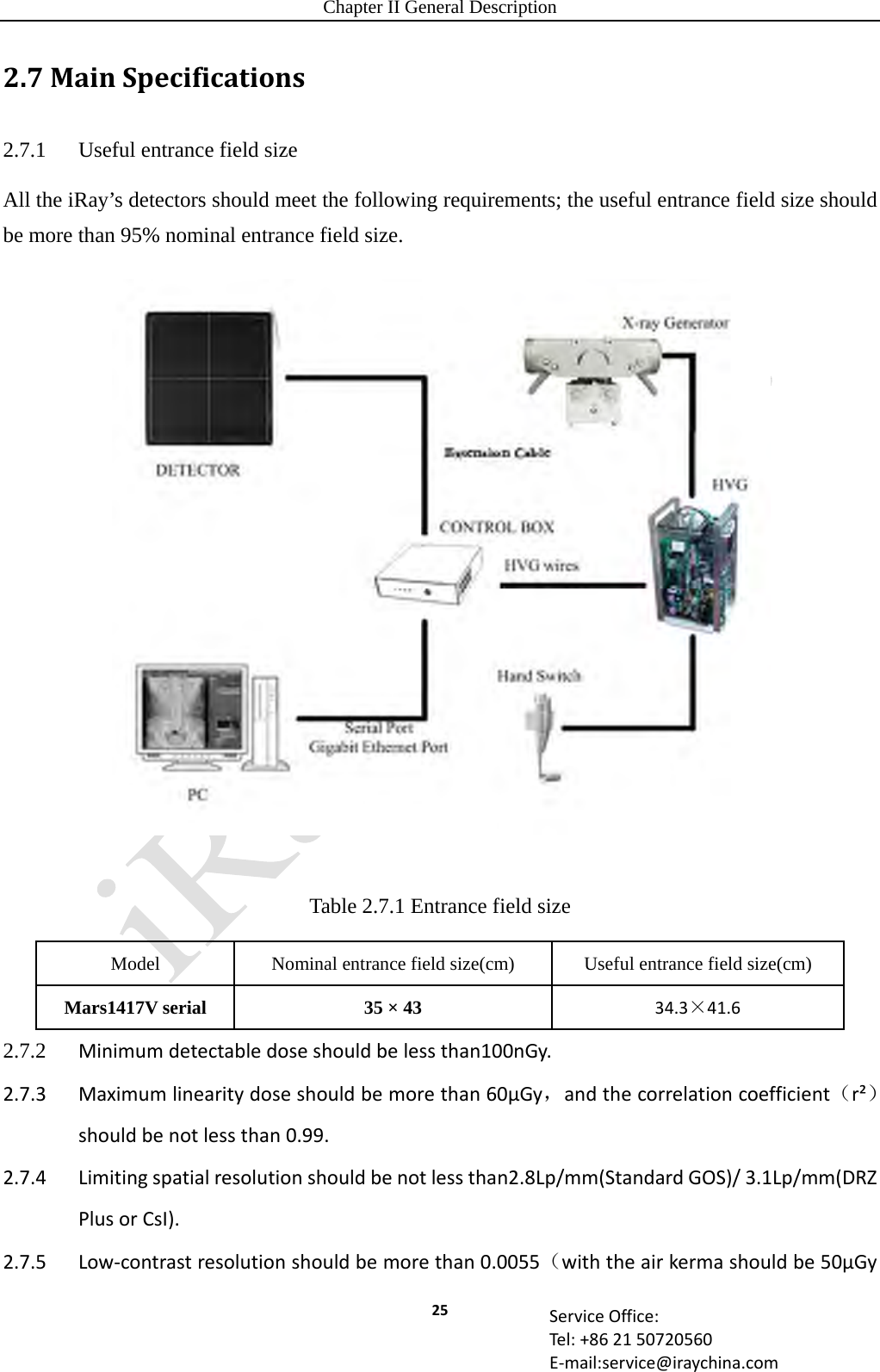
![Chapter II General Description 26 ServiceOffice:Tel:+862150720560E‐mail:service@iraychina.cominthetestprocess).2.7.6DefectsDefectsMaxNumberAllowedFullClass013500FullClass11500FullClass21050FullClass3300FullClass4150FullClass5120FullClass60FullClass70FullClass80Meta7+8Class10Meta7+8Class20Meta7+8Class30Meta7+8Class40Meta7+8Class50Meta7+8Class60Meta7+8Class70Meta7+8Class80SingleHorizontalDefectLines5SingleVerticalDefectLines5DoubleHorizontalDefectLines0DoubleVerticalDefectLines2DoubleVerticalDefectLinesinCentralArea0TripleVerticalorHorizontalLines0MinGapbetweenVerticalDefectLines/LinePairs10MinGapbetweenHorizontalDefectLines/LinePairs102.7.7Flatuniformityshouldbenotexceed2.2%2.7.8Modulationtransferfunction[MTF(u,v)]TheMTFshouldmeetthefollowingtableStandardradiationqualityNo.RQA/μGySpatialfrequency(lp/mm) MTF(DRZ‐Plus)MTF(CSI)5/2.50.5≥0.65≥0.771.0≥0.35≥0.581.5≥0.20≥0.392.0≥0.10≥0.252.5≥0.05≥0.153.3≥0.01≥0.10](https://usermanual.wiki/IRay-Technology/02112031/User-Guide-2430284-Page-26.png)
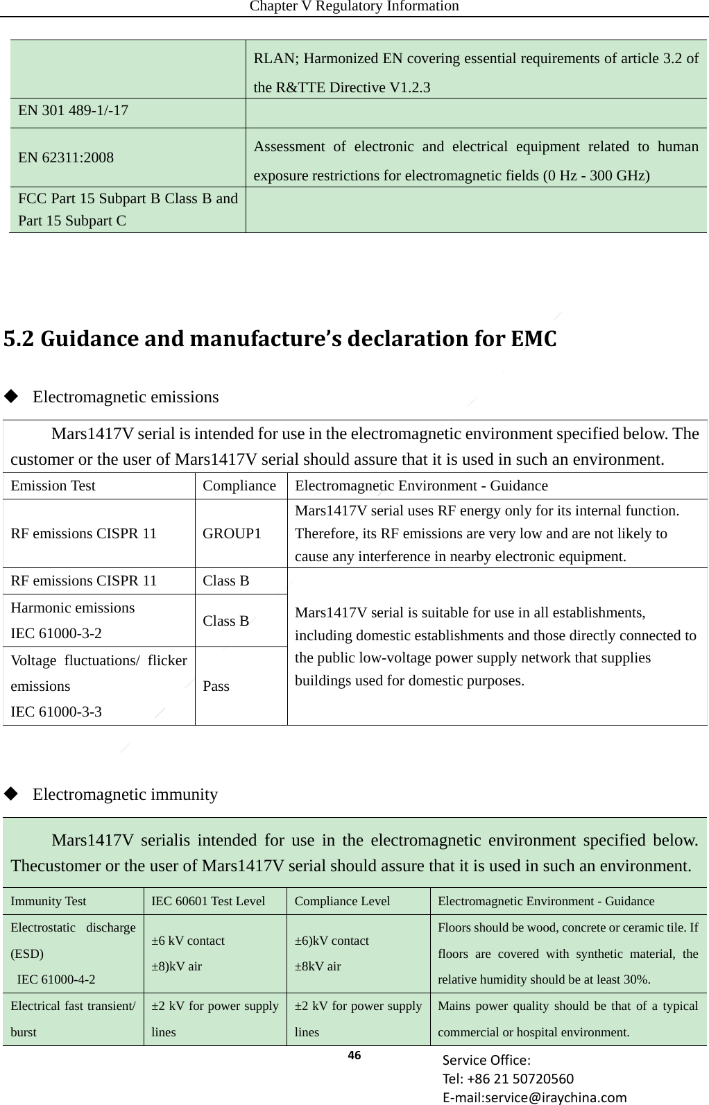
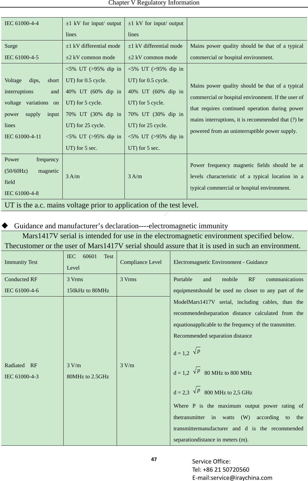
![Chapter V Regulatory Information 48 ServiceOffice:Tel:+862150720560E‐mail:service@iraychina.comField strengths from fixed RF transmitters, as determinedby an electromagnetic site survey, shouldbe less than the compliance level in each frequency range. Interference may occur in the vicinity of equipmentmarked with the following symbol: NOTE: UT is the a.c. mains voltage prior to application of the test level. NOTE1 At 80 MHz and 800 MHz, the higher frequency range applies. NOTE2 These guidelines may not apply in all situations. Electromagnetic propagation is affected by absorption and reflection from structures, objects and people. a Field strengths from fixed transmitters, such as base stations for radio (cellular/cordless) telephones and land mobile radios, amateur radio, AM and FM radio broadcast and TV broadcast cannot be predicted theoretically with accuracy. To assess the electromagnetic environment due to fixed RF transmitters, an electromagnetic site survey should be considered. If the measured field strength in the location in which Mars1417V serialis used exceeds the applicable RF compliance level above, Mars1417V serialshould be observed to verify normal operation. If abnormal performance is observed, additional measures may be necessary, such as re-orienting or relocating Mars1417V serial. b Over the frequency range 150 kHz to 80 MHz, field strengths should be less than [V1] V/m. Recommended separation distances between portable and mobile RF communications equipment and Mars1417V serial Mars1417V serial is intended for use in an electromagnetic environment in which radiated RF disturbances are controlled. The customer or the user of Mars1417V serial can help prevent electromagnetic interference by maintaining a minimum distance between portable and mobile RF communications equipment (transmitters) and Mars1417V serial as recommended below, according to the maximum output power of the communications equipment. Rated maximum output power of transmitter /W Separation distance according to frequency of transmitter /m 150kHz~80 MHz d = 1.2 p 80 MHz~800 MHz d = 1.2 p 800 MHz ~2.5GHz d = 2.3 p 0.01 0.12 0.12 0.23 0.1 0.38 0.38 0.73 1 1.2 1.2 2.3 10 3.8 3.8 7.3 100 12 12 23](https://usermanual.wiki/IRay-Technology/02112031/User-Guide-2430284-Page-48.png)