iRhythm Technologies AT18G Zio AT Gateway User Manual 3
iRhythm Technologies, Inc. Zio AT Gateway 3
Contents
- 1. User Manual
- 2. User Manual 2
- 3. User Manual 3
- 4. User Manual 1
User Manual 3

IMPORTANT INFORMATION
2 3
ABOUT THE ZIO AT
Zio AT data analysis
Your Zio AT data is analyzed at the iRhythm Clinical Centers.
iRhythm is an Independent Diagnostic Testing Facility (IDTF)
dedicated to providing world-class diagnostic service. As an
IDTF, we adhere to Medicare Independent Diagnostic Testing
Facility Performance Standards.
A link to these standards (42 C.F.R. Section 410.33) can be
found at the iRhythm website www.irhythmtech.com.
Patient identication
Before placing your device in the prepaid envelope, please
write your name on the line above the return address. By
writing your name on the envelope you are providing another
method of identication for the Patch and Gateway and are
consenting to the potential viewing of your name on the
envelope. You may choose to not write your name on the
envelope.
Notice of privacy practices
As participants in your health care, we are required by
applicable federal and state law to maintain the privacy of
your Protected Health Information (PHI).
Our full Notice of Privacy Practices, found at www.irhythmtech.
com, describes our privacy practices, our legal duties, and
your rights concerning your PHI.
Indications for use
The Zio AT ECG Monitoring System is intended to capture,
analyze and report symptomatic and asymptomatic cardiac
events and continuous electrocardiogram (ECG) information
for long-term monitoring. While continuously recording
patient ECG, both patient-triggered and automatically detected
arrhythmia events are transmitted to a monitoring center for
reporting. After wear, a nal report is generated based on
beat-to-beat information from the entire ECG recording. It is
indicated for use on patients 18 years or older who may be
asymptomatic or who may suer from transient symptoms
such as palpitations, shortness of breath, dizziness, light-
headedness, pre-syncope, syncope, fatigue, or anxiety. The
reports are provided for review by the intended user to render
a diagnosis based on clinical judgment and experience. It is
not intended for use on critical care patients.
Contraindications
• Do not use Zio AT for patients with symptomatic episodes
where variations in cardiac performance could result in
immediate danger to the patient or when real-time or in-
patient monitoring should be prescribed.
• Do not use the Zio AT for patients with known history of
life threatening arrhythmias.
• Do not use the Zio AT in combination with external cardiac
debrillators or high frequency surgical equipment near
strong magnetic elds or devices such as MRI.
• Do not use the Zio AT on patients with neuro-stimulator,
as it may disrupt the quality of ECG data.
• Do not use the Zio AT on patients who do not have the
competency to wear the device for the prescribed
monitoring period.
Warnings
• Do not use the Zio AT Patch on patients with known
allergic reaction to adhesives or hydrogels or with family
history of adhesive skin allergies. Patient may experience
skin irritation.
• Do not reuse the Zio AT Patch on multiple patients. It is
a single patient use device. Reuse will cause incorrect
patient data and patient may experience skin irritation.
• Do not use the Zio AT on patients residing in areas with
limited to no cellular reception.
• Do not modify the Zio AT system.

4 5
Warnings (cont’d)
• The Zio AT system is MR Unsafe!
- Do not expose the Zio AT patch or gateway to a magnetic
resonance (MR) environment.
- The Zio AT patch or gateway may present a risk of
projectile injury due to the presence of ferromagnetic
materials that can be attracted by the MR magnet core.
- Thermal injury and burns may occur due to the metal
components of the Zio AT patch that can heat during MR
scanning.
- The Zio AT patch may generate artifacts in the MR image.
- The Zio AT patch or gateway may not function properly
due to the strong magnetic and radiofrequency elds
generated by the MR scanner.
If skin irritation such as severe redness, itching or
allergic symptoms develop, remove the Zio AT Patch
from the patient’s chest. Call iRhythm Customer
Service at 1.888.693.2401
CAUTION: Federal (USA) law restricts the sale of this
device to or on the order of a physician.
Precautions
• Safety and eectiveness of the Zio AT Patch on
patients receiving any form of pacing therapy has not
been established. Paced cardiac rhythms may not be
accurately detected and may be incorrectly classied.
• Safety and eectiveness of the Zio AT system on pediatric
patients (younger than 18 years old) has not been
established.
• The Zio AT system includes temperature and humidity
limitations when stored/transported. If exposed during
storage/transport, patients may experience degradation
of adhesive performance causing the Zio AT patch to slip
or fall o during the patient wear duration.
• The Zio AT system has a shelf-life date. Use of expired
device may cause a degradation of ECG signal quality
and/or low battery condition.
• Do not use the Zio AT system if package is damaged.
Device may not perform as intended.
• Keep device and packaging away from young children.
Contents may be harmful if swallowed. Patch contains
button cell batteries that are not accessible during
normal use but, if exposed, are known choking hazards
and may cause severe tissue injury if ingested.
• Registration errors may result in limited functionality
or erroneous ECG reporting. Utmost caution should be
applied to ensure that patient registration is accurate and
complete.
The patient is an intended operator
Package Contents
1 Zio AT patch
1 Zio AT gateway, containing:
1 postage-paid return envelope
1 Skin Prep & Placement Kit containing:
1 patch card template
1 disposable razor
1 abrader disc
4 alcohol wipes
1 Application instructions
1 Wearing your Zio manual & button press log containing:
1 adhesive remover wipe
6 7
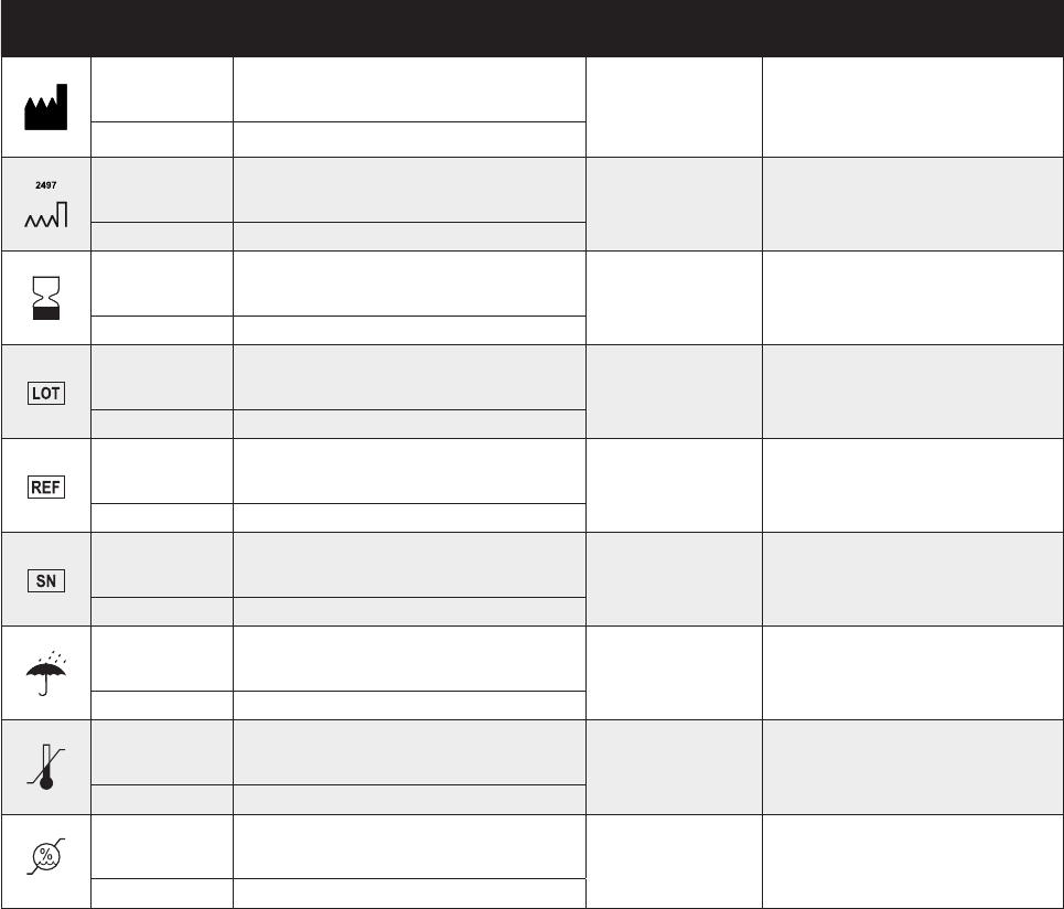
SYMBOL STANDARD
REFERENCE STANDARD TITLE SYMBOL TITLE DESCRIPTION/EXPLANITORY TEXT
ISO 15223-1 Clause 5.1.1
Medical devices — Symbols to be used with
medical device labels, labelling and
information to be supplied Manufacturer Indicates the medical device manufacturer.
ISO 7000-3082 Graphical symbols for use on equipment
ISO 15223-1 Clause 5.1.3
Medical devices — Symbols to be used with
medical device labels, labelling and
information to be supplied Date of manufacture Indicates the date when the medical device was
manufactured
ISO 7000-2497 Graphical symbols for use on equipment
ISO 15223-1 Clause 5.1.4
Medical devices — Symbols to be used with
medical device labels, labelling and
information to be supplied Use-by date Indicates the date after which the medical device is not
to be used.
ISO 7000-2607 Graphical symbols for use on equipment
ISO 15223-1 Clause 5.1.5
Medical devices — Symbols to be used with
medical device labels, labelling and
information to be supplied Batch code Indicates the manufacturer’s batch code so that the batch
or lot can be identied.
ISO 7000-2492 Graphical symbols for use on equipment
ISO 15223-1 Clause 5.1.6
Medical devices — Symbols to be used with
medical device labels, labelling and
information to be supplied Catalogue number Indicates the manufacturer’s catalogue number so that
the medical device can be identied.
ISO 7000-2493 Graphical symbols for use on equipment
ISO 15223-1 Clause 5.1.7
Medical devices — Symbols to be used with
medical device labels, labelling and
information to be supplied Serial number Indicates the manufacturer’s serial number so that a
specic medical device can be identied.
ISO 7000-2498 Graphical symbols for use on equipment
ISO 15223-1 Clause 5.3.4
Medical devices — Symbols to be used with
medical device labels, labelling and
information to be supplied Keep dry Indicates a medical device that needs to be protected
from moisture.
ISO 7000-0626 Graphical symbols for use on equipment
ISO 15223-1 Clause 5.3.7
Medical devices — Symbols to be used with
medical device labels, labelling and
information to be supplied Temperature limit Indicates the temperature limits to which the medical
device can be safely exposed.
ISO 7000-0632 Graphical symbols for use on equipment
ISO 15223-1 Clause 5.3.8
Medical devices — Symbols to be used with
medical device labels, labelling and
information to be supplied Humidity limitation Indicates the range of humidity to which the medical
device can be safely exposed.
ISO 7000-2620 Graphical symbols for use on equipment
Symbols Glossary
8 9
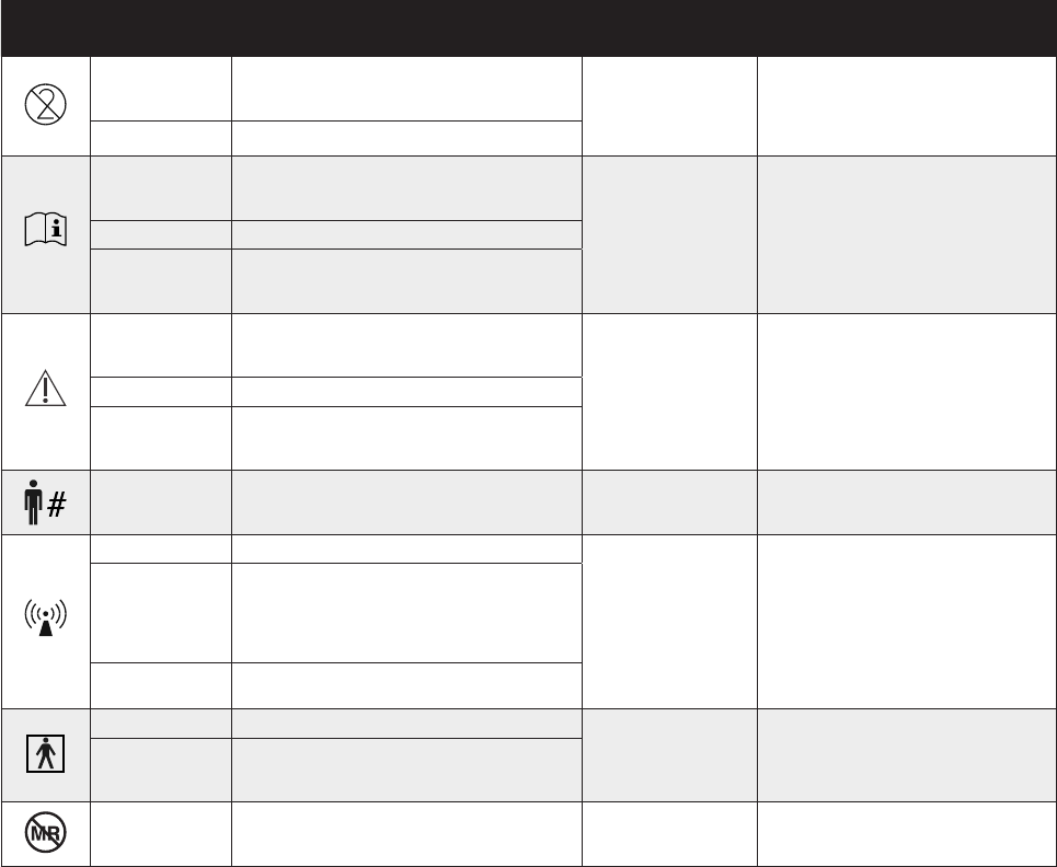
SYMBOL STANDARD
REFERENCE STANDARD TITLE SYMBOL TITLE DESCRIPTION/EXPLANITORY TEXT
ISO 15223-1 Clause 5.4.2
Medical devices — Symbols to be used with
medical device labels, labelling and
information to be supplied Do not re-use Indicates a medical device that is intended for one use, or
for use on a single patient during a single procedure.
ISO 7000-1051 Graphical symbols for use on equipment
ISO 15223-1 Clause 5.4.3
Medical devices — Symbols to be used with
medical device labels, labelling and
information to be supplied
Consult instructions for use Indicates the need for the user to consult the instructions
for use.
ISO 7000-1641 Graphical symbols for use on equipment
IEC 60601-1 Table D.1,
Symbol 11
Medical electrical equipment — Part 1: General
requirements for basic safety and essential
performance
ISO 15223-1 Clause 5.4.4
Medical devices — Symbols to be used with
medical device labels, labelling and informa-
tion to be supplied
Caution
Indicates the need for the user to consult the instructions
for use for important cautionary information such as
warnings and precautions that cannot, for a variety of
reasons, be presented on the medical device itself.
ISO 7000-0434 Graphical symbols for use on equipment
IEC 60601-1 Table D.1,
Symbol 10
Medical electrical equipment — Part 1: General
requirements for basic safety and essential
performance
ISO 15223-1 Clause 5.7.1
Medical devices — Symbols to be used with
medical device labels, labelling and
information to be supplied
Patient number Indicates a unique number associated with an individual
patient.
IEC 60417-5140 Graphical symbols for use on equipment
Non-ionizing electromagnetic
radiation
To indicate generally elevated, potentially hazardous,
levels of nonionizing radiation, or to indicate equipment or
systems e.g. in the medical electrical area that include RF
transmitters or that intentionally apply RF electromagnet-
ic energy for diagnosis or treatment.
IEC 60601-1-2:2007,
Clause 5.1.1
Medical electrical equipment — Part 1-2:
General requirements for basic safety and
essential performance — Collateral standard:
Electromagnetic compatibility — Requirements
and tests
IEC/TR 60878-5140 Graphical symbols for electrical equipment in
medical practice
IEC 60417-5333 Graphical symbols for use on equipment
Type BF Applied Part To identify a type BF applied part complying with IEC
60601-1.
IEC 60601-1, Table D.1,
Symbol 20
Medical electrical equipment — Part 1: General
requirements for basic safety and essential
performance
ASTM F2503-13
Standard Practice for Marking Medical Devices
and Other Items for Safety in the Magnetic
Resonance Environment
Magnetic Resonance (MR)
unsafe
Keep away from magnetic resonance imaging (MRI)
equipment.
Symbols Glossary (cont’d)
10 11
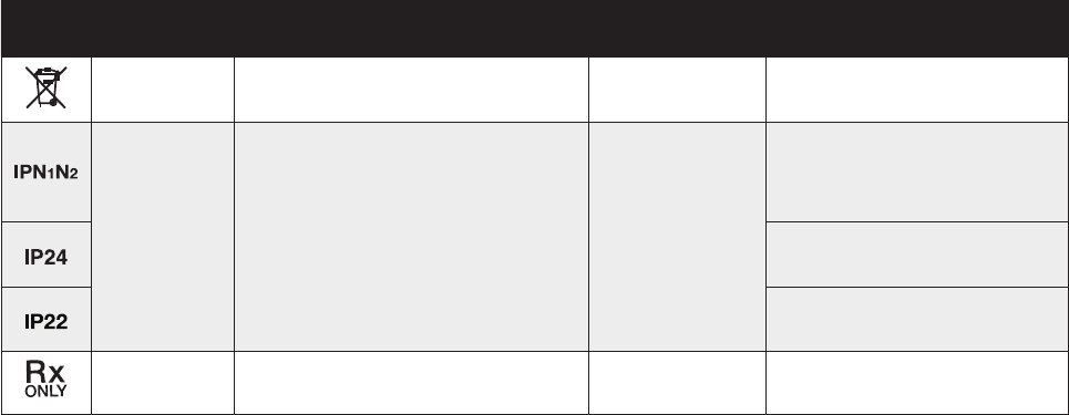
SYMBOL STANDARD
REFERENCE STANDARD TITLE SYMBOL TITLE DESCRIPTION/EXPLANITORY TEXT
BS EN 50419:2006
Marking of electrical and electronic equipment
in accordance with article 11(2) of Directive
2002/96/EC (WEEE)
Separate Collection To indicate that the product shall be separated when
disposed.
IEC 60601-1, Table D.3
Symbol 2
IEC 60529
Medical electrical equipment — Part 1: General
requirements for basic safety and essential
performance
Degrees of Protection Provided by Enclosures
(IP Code)
Degrees of protection provided
by enclosure
Manufacturer-determined degree of particle and water
ingress protection, where:
N1 = Degrees of protection against access to hazardous
parts
N2 = Degrees of protection against water
Protected against solid foreign objects of 12,5 mm
diameter and greater, and protected against splashing
water
Protected against solid foreign objects of 12,5 mm diam-
eter and greater, and protected against vertically falling
water drops when enclosure tilted up to 15°
21 CFR 801.15(c)(1)(i)F Labeling-Medical devices; prominence of
required label statements Prescription only Requires prescription in the United States
Symbols Glossary (cont’d)
12 13
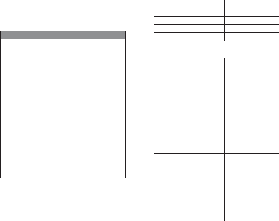
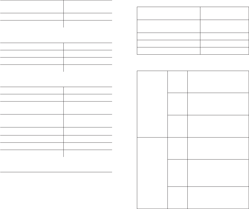
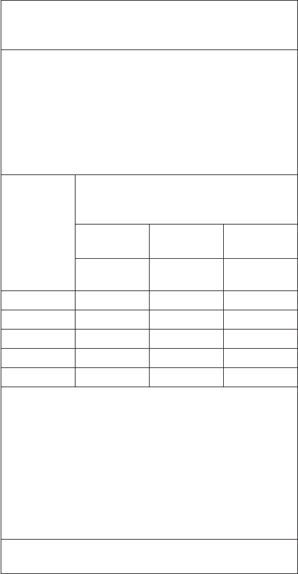
Asymptomatic Arrhythmia Detection
Asymptomatic arrhythmia events, as detected and transmitted
during the monitoring period, are dened by the following
parameters:
Rhythm Heart Rate Duration
Atrial Fibrillation
≤40
bpm ≥60 seconds
≤180
bpm ≥60 seconds
Pause
-≥4 seconds
-≥3 seconds
back-to-back
Ventricular
Tachycardia
≥ 120
bpm ≥ 30 seconds
≥150
bpm ≥15 seconds
Complete Heart Block
(day 05:00~23:00)
≤ 50
bpm ≥6 beats
Complete Heart Block
(night 23:00~05:00)
≤ 47
bpm ≥6 beats
Bradycardia ≤30
bpm ≥60 seconds
Tachycardia ≥ 200
bpm ≥ 60 seconds
PATCH PERFORMANCE CHARACTERISTICS
ECG Channels 1 channel
Memory capacity 14 days
Recording Format Continuous
Service Life Up to 14 days
Shelf Life 2 months
ELECTRICAL CHARACTERISTICS
Medical Equipment Type BF Applied Part
ECG Frequency Response 0.5Hz to 30Hz
ECG Input Impedance ≥ 10 MΩ
ECG Dierential Range ±1.65 mV
ECG A/D Sampling Rate 200 Hz
ECG Resolution 10 bits
Patch Short-range RF
Transmit/Receive
2.4 GHz Bluetooth
Low Energy
Eective Radiated
Power < 1mW
Frequency Band of Transmission 2.4 GHz
Bandwidth of the Receiver 2400-2480 MHz
Type and Frequency of
Modulation 1-Mbps GFSK
Gateway Short-range
RF Transmit/Receive
2.4 GHz Bluetooth
Low Energy
Eective Radiated
Power < 1mW
Gateway Cellular RF Transmit/
Receive
800 / 1900 MHz CDMA
Eective Radiated
Power ≤300mW
750 MHz LTE Cat M1
Power < 200 mW
14 15
POWER CHARACTERISTICS
Patch Battery Type 2 Lithium Manganese
Dioxide Coin Cells
Gateway Battery Type 1 Lithium Polymer Cell
Battery Life 14 days
PHYSICAL CHARACTERISTICS
Patch Dimensions 5.2 x 2.0 x 0.5 inches
Patch Weight 24.7 g
Gateway Dimensions 6.2 x 3.4 x 0.8 inches
Gateway Weight 158 g
ENVIRONMENTAL CHARACTERISTICS
Operational Temperature 41 to 104 degrees F
Operational Altitude -1,000 to 10,000 ft
Operational & Storage Humidity 10% to 95%
(non-condensing)
Shipping (Short-term Storage)
Temperature
-4 to 104 degrees F
Long-term Storage Temperature 55 to 85 degrees F
Storage Altitude -1,000 to 14,000 ft
Patch IP Classication IP24
Gateway IP Classication IP22
ESSENTIAL PERFORMANCE
The Zio AT system records and transmits ECG for analysis
after receipt of data. In the event it cannot record or
transmit in a timely fashion, the Zio AT alerts the patient
that functionality is impaired.
EQUIPMENT CLASSIFICATION
INFORMATION
Patch IEC
Classications
Gateway IEC
Classications
Internally Powered
ME Equipment
Internally Powered
ME Equipment
Type BF Applied Part -
IPX4 - IP 22
Continuous Operation Continuous Operation
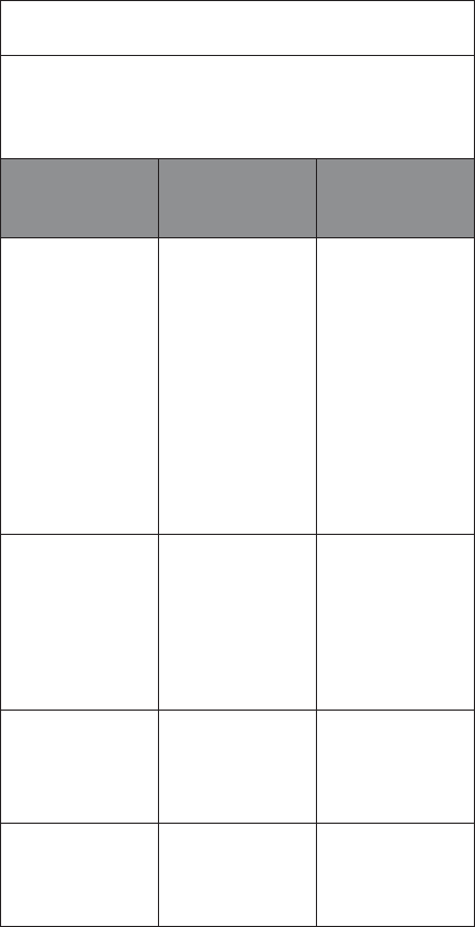
Heart Rate Calculations
Episode
Heart
Rates
Max
The maximum episode heart
rate (i.e., maximum of all
instantaneous heart rates
within the episode)
Min
The minimum episode heart
rate (i.e., minimum of all
instantaneous heart rates
within the episode)
Avg
The average episode heart rate
(i.e., average of all
instantaneous heart rates
within the episode)
Overall
Rhythm
Heart
Rates
Max
The maximum overall heart
rate (i.e., maximum of all
rhythm episode maximum heart
rates within the record)
Min
The minimum overall heart rate
(i.e., minimum of all rhythm
episode minimum heart rates
exclusive of Pause heart rates
within the record)
Avg
The average overall heart rate
(i.e., duration-weighted average
of all rhythm episode heart
rates within the record)
16 17
Pause Determination
Pause is dened as an RR interval greater than 3 seconds.
Electrical Safety and Compatibility
• CAUTION: The Zio AT system needs special precautions
regarding EMC and needs to be utilized according to the
EMC
information provided in the following tables.
• CAUTION: Portable and mobile RF communications
equipment can aect medical electrical equipment.
• WARNING: The Zio AT system should not be used adjacent
to or stacked with other equipment.
• WARNING: The Zio AT system may be interfered with by
other equipment, even if that other equipment complies
with CISPR EMISSIONS requirements.
• WARNING: Portable RF communications equipment
(including peripherals such as antenna cables and
external antennas) should be used no closer than
30 cm (12 inches) to any part of the Zio AT patch or
gateway. Otherwise, degradation of the performance of
this equipment could result.
Table 1: Guidance and manufacturer’s declaration—
electromagnetic emissions
The Zio AT system is intended for use in the electromagnetic
environment specied below. The customer or the user of
the Zio AT system should assure that it is used in such an
environment.
Emissions test Compliance Electromagnetic
environment -
guidance
RF emissions
CISPR 11 Group 1
The Zio AT
system uses RF
energy only for its
internal function.
Therefore, its
RF emissions
are very low and
are not likely
to cause any
interference in
nearby electronic
equipment.
RF emissions
CISPR 11 Class B
The Zio AT
system is suitable
for use in all
establishments,
including
domestic
establishments.
Harmonic
emissions
IEC 61000-3-2 Not applicable Not applicable
Voltage
uctuations/
icker emissions
IEC
Not applicable Not applicable
18 19
Table 2: Guidance and manufacturer’s declaration—
electromagnetic immunity
The Zio AT system is intended for use in the electromagnetic
environment specied below. The customer or the user of
the Zio AT system should assure that it is used in such an
environment.
Immunity
test
IEC 60601
test level
Compliance
level
Electromagnetic
environment -
guidance
Electrostatic
Discharge
(ESD)
IEC 61000-
4-2
±8 kV
contact
±15 kV
air
±8 kV
contact
±15 kV
air
Floors should be
wood, concrete,
or ceramic
tile. If oors
are covered
with synthetic
material, the
relative humidity
should be at
least 30 %.
Power
frequency
(50/60 Hz)
magnetic
eld
IEC 61000-
4-8
30 A/m 30 A/m
Power frequency
magnetic
elds should
be at levels
characteristic of
a typical location
in a typical
commercial
or hospital
environment.
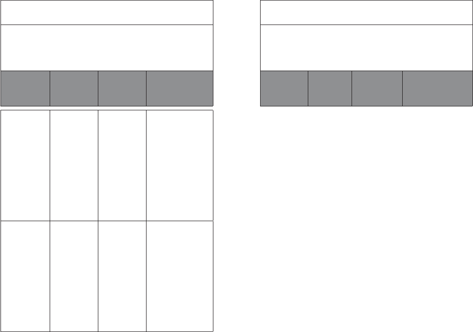
Table 3: Guidance and manufacturer’s declaration—
electromagnetic immunity
The Zio AT system is intended for use in the electromagnetic
environment specied below. The customer or the user of
the Zio AT system should assure that it is used in such an
environment.
Immunity
test
IEC 60601
test level
Compliance
level
Electromagnetic
environment -
guidance
Continued on next page
20 21
NOTE 1—At 80 MHz and 800 MHz, the higher frequency
range applies.
NOTE 2—These guidelines may not apply in all situations.
Electromagnetic propagation is aected by absorption and
reection from structures, objects, and people.
a Field strengths from xed transmitters, such as base
stations for radio (cellular/cordless) telephones and land
mobile radios, amateur radio, AM and FM radio broadcast,
and TV broadcast cannot be predicted theoretically with
accuracy. To assess the electromagnetic environment due
to xed RF transmitters, an electromagnetic site survey
should be considered. If the measured eld strength in the
location in which the Zio AT system is used exceeds the
applicable RF compliance level above, the Zio AT system
should be observed to verify normal operation. If abnormal
performance is observed, additional measures may be
necessary, such as re-orienting or relocating the Zio AT
patch or gateway.
b Over the frequency range 150 kHz to 80 MHz, eld
strengths should be less than 3 V/m.
Radiated
RF
IEC 61000-
4-3
10 V/m
80 MHz to
2.7 GHz
28 V/m
385, 450,
810, 870,
930 MHz
18 Hz
pulse
9 V/m
710, 745,
780 MHz
217 Hz
pulse
28 V/m
1720,
1845,
1970,
2450 MHz
217 Hz
pulse
9 V/m
5240,
5500,
5783 MHz
217 Hz
pulse
10 V/m
28 V/m
9 V/m
28 V/m
9 V/m
Portable and mobile
RF communications
equipment should
be used no closer
to any part of
the Zio AT system,
including cables, than
the recommended
separation distance
calculated from the
equation applicable to
the frequency of the
transmitter.
Recommended
separation distance
d = 1.2√P
d = 1.2√P 80 MHz to
800 MHz
d = 2.3√P 800 MHz to
2.5 GHz
where P is the
maximum output
power rating of
the transmitter in
watts (W) according
to the transmitter
manufacturer and d
is the recommended
separation distance in
meters (m).
Field strengths from
xed RF transmitters,
as determined by
an electromagnetic
site survey,a should
be less than the
compliance level
in each frequency
range.b
Interference may
occur in the vicinity
of equipment marked
with the following
symbol:
22 23
This system complies with part 15 of the FCC Rules. Operation
is subject to the following two conditions: (1) this system may
not cause harmful interference, and (2) this system must
accept any interference received, including interference that
may cause undesired operation.
For body worn operation, this system has been tested
and meets FCC RF exposure guidelines when used with
an accessory that contains no metal, such as the belt clip
provided, and that positions the Gateway a minimum 1 cm
from the body. Use of other accessories may not ensure
compliance with FCC RF exposure guidelines.
Changes or modications not expressly approved by the party
responsible for compliance could void the user’s authority to
operate the equipment.
The gateway has been tested and meets FCC RF exposure
guidelines when used and operated for its intended purpose
and as instructed in the manual.
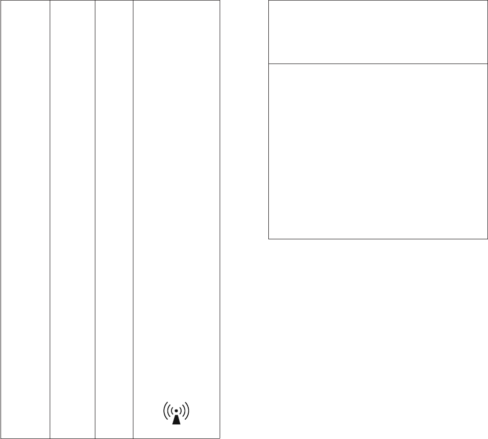
Table 4: Recommended separation distances between
portable and mobile RF communications equipment and the
Zio AT system.
The Zio AT system is intended for use in an electromagnetic
environment in which radiated RF disturbances are
controlled. The customer or the user of the Zio AT
system can help prevent electromagnetic interference by
maintaining a minimum distance between portable and
mobile RF communications equipment (transmitters) and
the Zio AT system as recommended below, according to the
maximum output power of the communications equipment.
Rated
maximum
output
power of
transmitter
W
Separation distance according to
frequency of transmitter
m
150 kHz to
80 MHz
80 MHz to
800 MHz
80 MHz to
2.5 GHz
d = 1.2√P d = 1.2√P d = 2.3√P
0.01 0.12 0.12 0.23
0.1 0.38 0.38 0.73
1 1.2 1.2 2.3
10 3.8 3.8 7.3
100 12 12 23
For transmitters rated at a maximum output power not
listed above, the recommended separation distance d in
meters (m) can be determined using the equation applicable
to the frequency of the transmitter, where P is the maximum
output power rating of the transmitter in watts (W)
according to the transmitter manufacturer.
NOTE 1—At 80 MHz and 800 MHz, the separation distance
for the higher frequency range applies.
NOTE 2—These guidelines may not apply in all situations.
Electromagnetic propagation is aected by absorption and
reection from structures, objects, and people.
ALB0032.01 • 2018-04-11
iRhythm Technologies, Inc.
650 Townsend St., Suite 500
San Francisco, CA 94103 USA
1.888.693.2401
irhythmtech.com