iWaylink IT7000PDT-B PDT (Portable Data Terminal) User Manual User s manual rev2
Bitatek Co., Ltd. PDT (Portable Data Terminal) User s manual rev2
iWaylink >
Users Manual

IT7000 User’s Guide
WinCE. NET Rugged PDA
Dec. 04, 2004

Table of Contents
Chapter 1. Introduction
1.1: About this Manual
1.2: User and Product Safety
1.3: Agency Compliance
1.4: Product Labeling
1.5: System specifications
1.6: Environment standard
1.7: Warranty and after service
Chapter 2. Getting Started
2.1: Check the Package
2.2: General view of the PDA
2.2.1: PDA front side view
2.2.2: PDA back side view
2.3: Charging the Battery pack
2.3.1: Installing the Battery pack
2.3.2: Charging the battery pack with Power adapter
2.3.3: Charging the battery pack with Single Cradle
2.4: Handling the PDA
2.4.1 Starting the PDA
2.4.2: Power (and Backlight) on / off
2.4.3: Calibration of the touch screen
2.4.4: Adjusting the brightness
2.4.5: To mute the Sound
2.4.6: Using the Stylus
2.4.7: Using the Keypad
2.4.8: Using the Ear/Microphone
2.5: Navigating the Display
2.5.1: Setting the Time and Date
2.5.2: entering the Data
2.5.3: The Command Bar
2.5.4: The Task Bar
2.5.5: The Soft Keypad
2.5.6: Initiating a Network Connection
2.5.7: Scanning Barcode
2.5.8: Rotating the Screen
2.5.9: Help
2.6: Power management
2.6.1: Suspend mode
2.6.2: Resuming
i

2.7: Resetting the PDA
2.7.1: Software (Warm) Reset
2.7.2: Cold Reset
Chapter 3. Setting
3.1: Introduction
3.2: Control Panel
3.2.1 Backup Restore
3.2.2 Bar Code Setting
3.2.3 Symbologies List
3.2.4 Brightness
3.2.5 Certificates
3.2.6 CPU Speed
3.2.7 Date/Time
3.2.8 Dialing Properties
3.2.9 Display Properties
3.2.10 Fkey Settings
3.2.11 Information
3.2.12 Input Panel
3.2.13 Internet Options
3.2.14 Keyboard
3.2.15 Mouse
3.2.16 Network and Dial-up Connections
3.2.17 Owner
3.2.18 Password
3.2.19 PC Connection
3.2.20 Power
3.2.21 Regional Settings
3.2.22 Remove Programs
3.2.23 Storage Manager
3.2.24 Stylus
3.2.25 system
3.2.26 Volume & Sounds Properties
3.3 :Taskbar and Start Menu
Chapter 4. Communication
4.1: Installing & Setting Up Microsoft ActiveSync
4.1.1 Installing Microsoft ActiveSync on the Host PC
ii

4.1.2 Connecting PDA to Host PC
4.2: Using ActiveSync
4.2.1 Setting up a partnership
4.2.2 ActiveSync File Synchronization
4.3 Networking
iii

Chapter 1
Introduction
Congratulations on purchasing the IT7000 PDA, a Microsoft Windows®CE .Net rugged
PDA. Its special combination of features make it perfect for using in a wide range of
applications. These features as:
․Small rugged lightweight form factor
․Microsoft Windows CE. Net operating system
․Flexible module design
․Wireless mobility via 802.11b (Bluetooth by optional)
․Robust expansion capability
․Long battery life
․Transflective type color LCD display
․Backlit keypad
1.1 About this Manual
The following chapters contained in this manual are:
Chapter 1: Introduction --- Present the general information about the PDA.
Chapter 2: Getting started --- Describe the basic use of the PDA.
Chapter 3:Setting – Provide basic instructions for customizing the PDA by adjusting
settings
Chapter 4:Communication--- Describe how to use all kinds of communication of the
PDA.
1.2 User and Product Safety
◆ Do not stare into the laser beam directly or shine it into eyes.
◆ Never use strong pressure onto the screen or subject it to severe impact, as the LCD
panel could become cracked and possibility cause personal injury. If the LCD panel
is broken, never touch the liquid inside, for such contact would irritate the skin.
P.1-1

◆ Although the IT7000 PDA has been passed the test of IP64 standard for water and
dust resistance, avoid prolonged exposure to rain or other concentrated moisture.
For these conditions exceed the IP64 standard, and could result in water or other
contaminants entering into the PDA.
◆ Use only the approved AC Adapter with the PDA. Use of an unapproved AC
Adapter could result in electrical problems, or even cause a fire or electrical shock
to the user.
◆ Be sure that only authorized supplier are allowed to disassemble and reassemble the
device. If the device or parts has been damaged due to any wrong handling, shall
void the product and parts warranty.
◆ Always make back-up copies of all important data. Easy done by using a cable or
Single Cradle (sold by optional) to transfer data to the computer. Manufacturer is
not liable for any data damages or data loss caused by deletion or corruption by
using of this device, or due to the drained battery.
◆ Lithium-ion battery packs might get hot, explode, ignite and/or cause serious injury
if exploded by abusive using. Please follow the safety warnings listed as below:
․Do not place the battery pack in fire or heat the battery.
․Do not install the battery pack backwards so the polarity is reserved.
․Do not connect the positive Battery pack with negative battery pack to each other
with any metal object (like wire).
․Do not carry or store battery pack together with metal objects.
․Do not pierce the battery pack with nails, strike the battery pack with a hammer,
step on the battery pack or otherwise put it to strong impacts or shocks.
․Do not solder directly onto the battery pack.
․Do not expose battery pack to liquid, or allow the battery contacts to get wet.
․Do not disassemble or modify the battery pack. The battery pack contains
safety and protection devices, which, if damaged, may cause the battery pack
to generate heat, explode or ignite.
․Do not discharge the battery pack using any device except for the specified
device. When it is used in devices other than the specified devices, the battery
pack can be damaged or its life expectancy reduced. If the device causes any
abnormal current to flow, it may cause the battery pack to become hot, explode or
ignite and cause serious injury.
․In the event the battery pack leaks and the fluid gets into one’s eye, do not rub the
eye. Rinse well with water and immediately seek medical care. If left untreated,
the battery fluid could cause damage to the eye.
P1-2

1.3 Radio Frequency Interference Information
1.3.1 FCC Radiation Exposure Statement:
This equipment has been tested and found to comply with the limits for a Class
B digital device, pursuant to Part 15 of the FCC Rules. These limits are
designed to provide reasonable protection against harmful interference in a
residential installation. This equipment generates, uses and can radiate radio
frequency energy and, if not installed and used in accordance with the
instructions, may cause harmful interference to radio communications.
However, there is no guarantee that interference will not occur in a particular
installation. If this equipment does cause harmful interference to radio or
television reception, which can be determined by turning the equipment off and
on, the user is encouraged to try to correct the interference by one of the
following measures:
- Reorient or relocate the receiving antenna.
- Increase the separation between the equipment and receiver.
- Connect the equipment into an outlet on a circuit different from that
to which the receiver is connected.
- Consult the dealer or an experienced radio/TV technician for help.
FCC Caution: Any changes or modifications not expressly approved by the
party responsible for compliance could void the user's authority to operate this
equipment.
This device complies with Part 15 of the FCC Rules. Operation is subject to the
following two conditions: (1) This device may not cause harmful interference,
and (2) this device must accept any interference received, including
interference that may cause undesired operation.
P1-3

IMPORTANT NOTE:
FCC Radiation Exposure Statement:
This equipment complies with FCC RF radiation exposure limits set forth for an
uncontrolled environment. To maintain compliance with FCC RF exposure
compliance requirements, please avoid direct contact to the transmitting
antenna during transmitting. This transmitter must not be co-located or
operating in conjunction with any other antenna or transmitter.
Caution: The FCC ID of IT7000 is SPY-IT7000PDT-B
P1-4
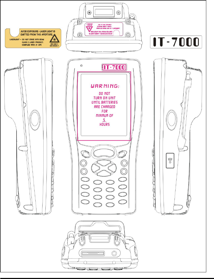
1.4 Product Labeling
The PDA has several labels as showed in Figure 1-1 and 1-2.
Figure. 1-1 Product Labeling (Front side view)
P1-5

1.5 System Specifications
The IT7000 PDA detailed specifications as follows. Unless otherwise noted, all the
specifications are subject to change without prior notification.
System Specification
IT7000
Processor - Intel® XScale PXA255 400Mhz 32 bits RISC
Memory - 64MB (M-System) Flash ROM
- 64 or 128MB SDRAM
Display - Support 240 x 320 TFT 256K Color LCD
- Transflective type TFT LCD with back light
Audio
- One mono speaker
- 2.5mm DIA stereo earphone jack with Microphone
input
Radio Support -Wireless LAN: 802.11b
-Bluetooth: Class II (optional)
Communication Ports
-Infrared: One IrDA 1.2 compliant port
-USB: Support USB v1.1 both host and client
(PDA and Cradle)
-Serial: RS232 via optional cable or Cradle
Scan Engine
-Default: Symbol SE800
-Optional: Symbol SE900, Opticon VLM4000,
Intermec EV-10 CCD, HHP 4080 2D Imager.
Expansion Slot - One Compact Flash Type-II slot (support 3.3V)
- One SD Card slot (support SD memory)
LED
- One three-color LED for Alarm notification (Blue)
and charger indicator (RED & Green)
- One two-color LED for scanner indicator
P1-7

Power System
- Built in 7.4V, 2200mAh Li-ion removable battery pack
(10 operation hours & 100 standby hours in 64MB
DRAM and 64 ROM module)
- 140mA rechargeable backup battery (It will hold the
system data at least 3 hours)
Button/Key
- Power/Front light on/off button
- LED light Key
- 4-way navigation button
- 4 Application Keys
- 3 Scanner Enable Keys
- SW Reset input button
-16 alphanumeric keyboard
Dimensions and
Weight
- Dimensions: 91/76mm (W) x 187mm (L) x 58/43mm
(H)
- Weight: 350g
Color - Black
Peripherals and
Accessories Optional: Pistol Grip/ Single Cradle/ Ethernet Module
Software - Microsoft WinCE.NET 4.2 (Professional Version)
1.6 Environment Standard:
Storage Temperature -20℃~60℃
Operating Temperature -10℃~50℃
Humidity 5% to 90% (non-condensing)
Drop 5ft (1.5m) drop to concrete
Water & Dust proof IEC 529 rating IP64DW
Vibration MIL STD 810F
P1-8

1.7 Warranty and after service
Should this PDA be malfunctioned, please contact your original retailer providing
information about the product name, the serial number, and the details about the
problem.
P1-9
Chapter 2
Getting Started
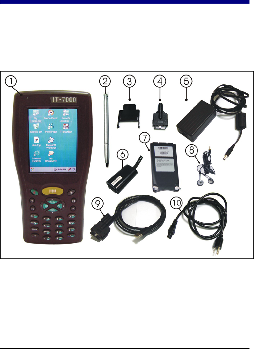
2.1 Check the package
Open the package and check all the parts are inside without shortage and damage:
Figure 2-1 Inside the package
1. IT7000 2. Stylus
3. CF support Guide 4. DC-IN Converter
5. Standard AC Adapter 6. Standard Battery Pack
7. Cover of Battery Pack 8. Earphone Set with Microphone
9. USB Client Sync cable 10. Power Cord
11. Quick guide (Not shown) 12. User’s Guide CD (Not shown)
P2-1
2.2 General View of the PDA
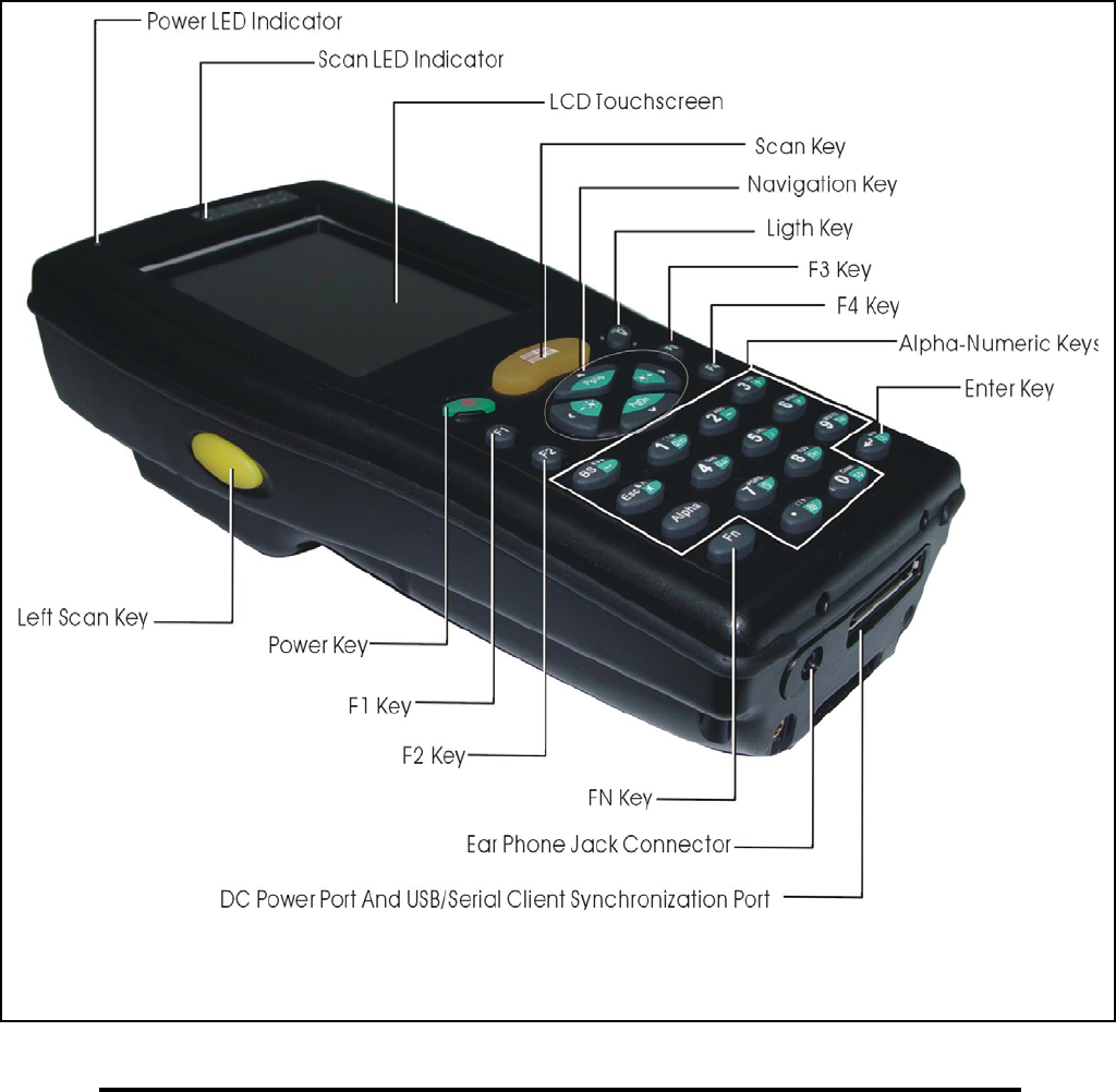
2.2.1: PDA front side view
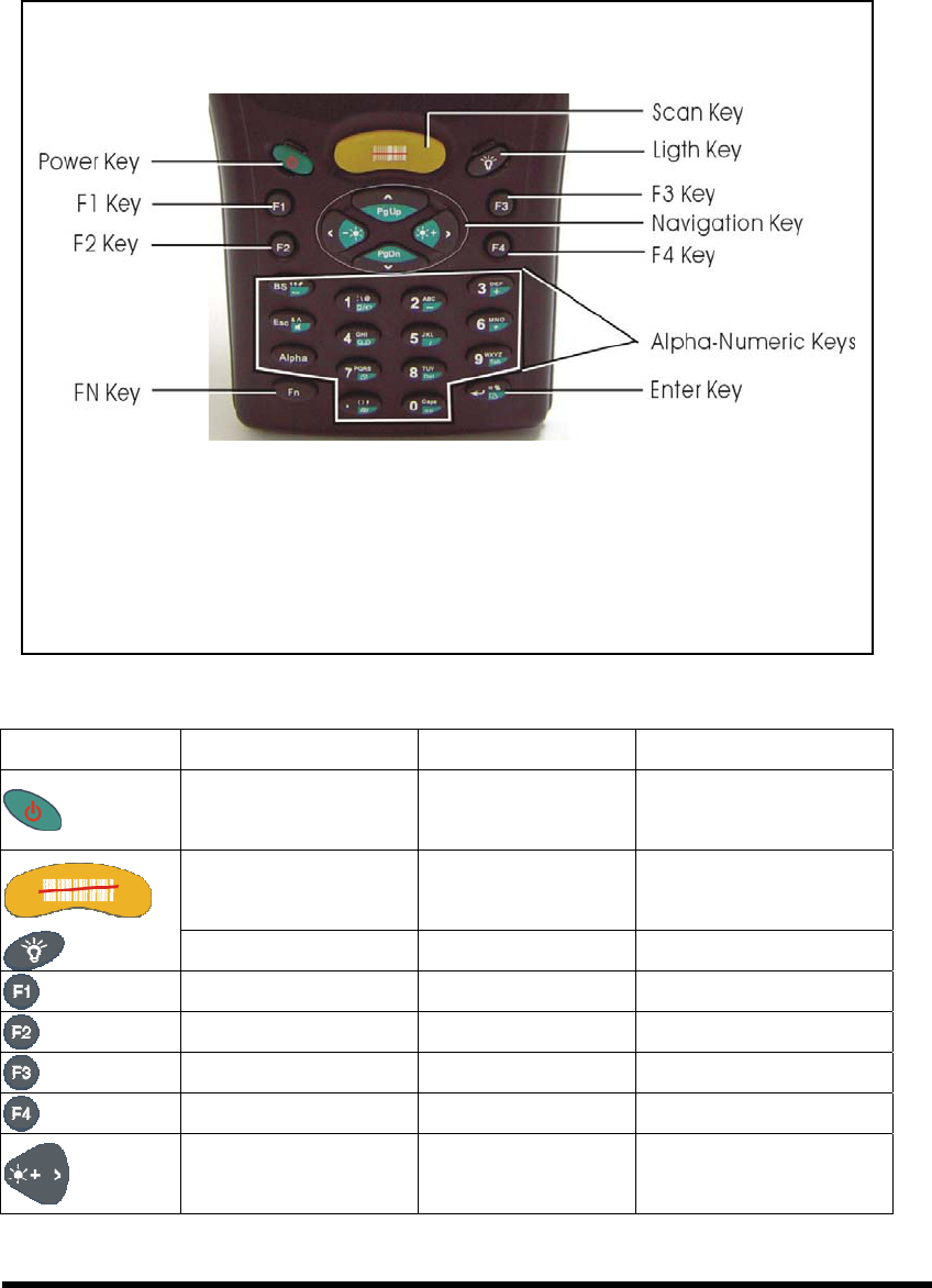
Figure 2-2 PDA Front side view
P2-2
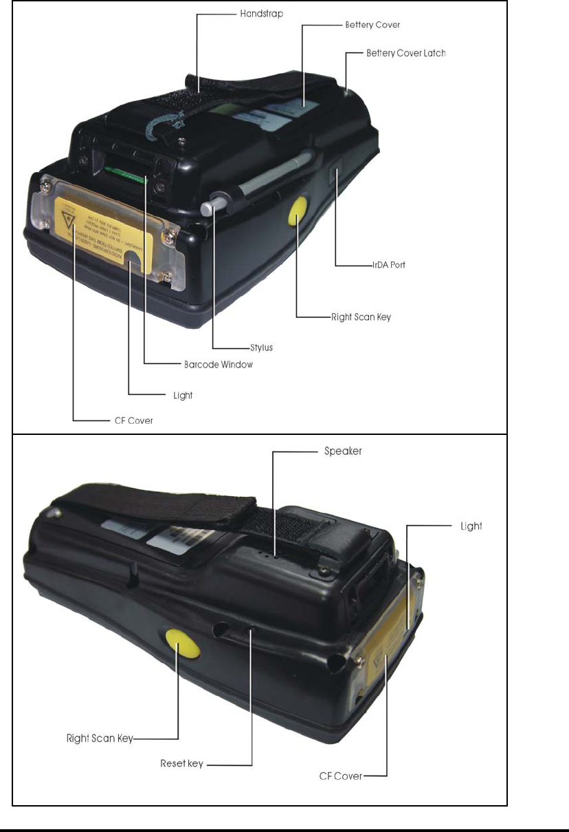
2.2.2: PDA back side view
Figure 2-3 PDA back side view
P2-3

Table 2-1 Description of PDA General View
“Red” color Reading barcode 1 Scanner LED Indicator
“Green” color successful reading
“Blue” color Blinking for alarm
“Red” color Charging battery
2 Alarm/Charge LED
Indicator
“Green” color Battery charged full
3 LCM/ Touch Panel Do specific action through touch panel by stylus
4 Left Scan key
Right Scan key
Scan key
Start scanning the barcode by pressing any one of
these three scan keys
5 Power/Backlight key
1. Puts the terminal into and wakes the terminal from
suspend mode if this key button isn't pressed more
than two seconds.
2. Turns on/off the LED backlight of LCM if this key
button is pressed more than two seconds.
6 Light key Turn the front illumination LED on/off
7 F1 key~ F4 key The four application keys, hot keys of application
program defined by end user.
8 Navigation key Navigation keys for left, right, up and down
directions
9 Alpha-Numeric keys Numeric keys, Change to Alpha keys after pressing
Alpha key.
10 Alpha key Toggle Alpha-mode for Alpha-Numeric keys
11 Fn key This key is used in combination with other keys to type
special characters and perform system functions.
12 Enter key This key confirms data entry
13 Ear phone Jack
Connector
A connector to plug a earphone set with microphone
14 DC power /USB /Serial
/Synchronization port
A connector to support DC power, USB Host/Client
and serial functions
15 CF Cover Protect CF connector and SD connector from dust and
water
16 Light A white LED flashlight
17 Barcode window A window for scanning of barcode reader
P2-4

18 stylus Use the stylus for selecting items and entering
information.
19 IrDA port Provide SIR function
20 Battery Cover Protect Battery pack, keep the switch of battery cover
to leave system from suspend mode
21 Battery cover Latch To keep Battery Cover locked
22 Hand strap This strap can be sealed tighter or looser
23 Speaker 0.5W speaker for audio sound
24 Reset Button A button for software reset
P2-5
2.3 Charging the Battery Pack
Before using the PDA, perform the basic procedure of charging the battery pack
through the following steps.
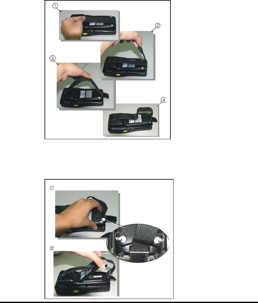
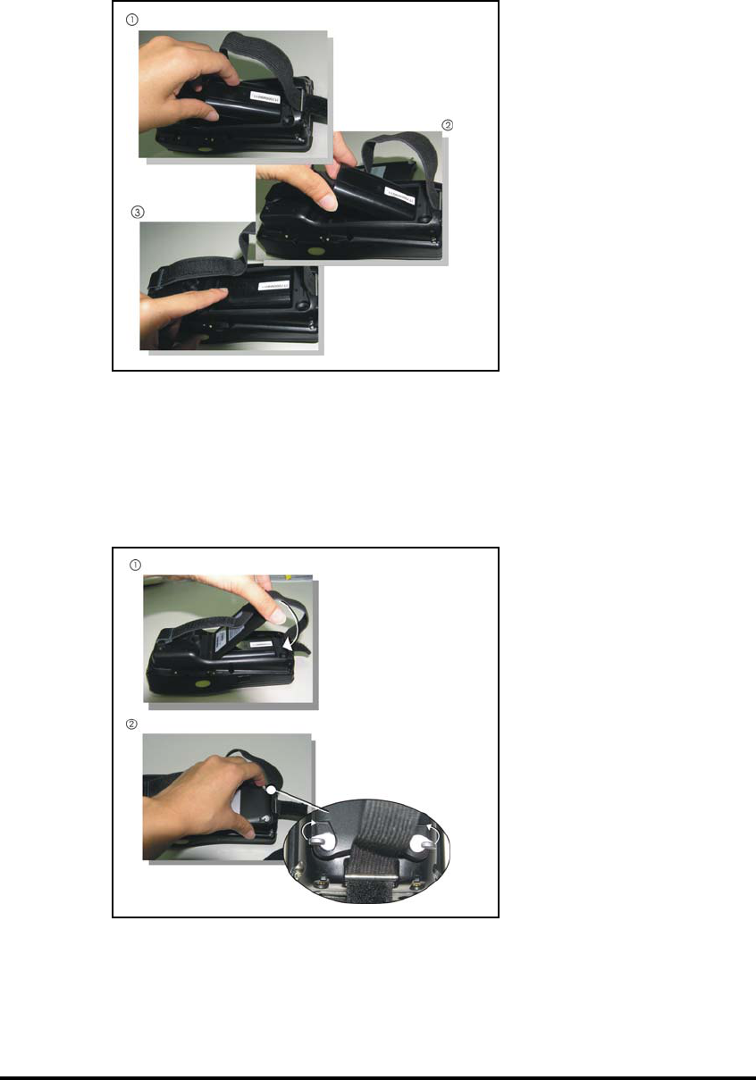
2.3.1 Installing the battery pack
1. On the PDA attached with a hand-strap, detach and loose the hand-strap.
Figure 2-4 Release the Hand strap from PDA
2. Turn the locking screws (right and left) downwards and lift the battery cover away
from the PDA.
Figure 2-5 Detach the battery cover from PDA
P2-6
3. Insert the battery pack into the battery compartment with the label facing out, and
ensuring the battery snaps into place.
Figure 2-6 Insert the battery pack
3. Replace the battery cover by inserting the top first, and then press the bottom in firmly.
Turn the locking screws (right and left) upwards to secure the cover to the PDA.
Figure 2-7 Replace the battery cover
4. Charge time. For the first time to charge the battery pack needs approximately 5
hours. Subsequent charging time needs approximately 3 hours.
◆. When charging the battery pack, the Power LED on the PDA turns on Red. After
the battery pack is fully charged, the Power LED turns to green.
P2-7
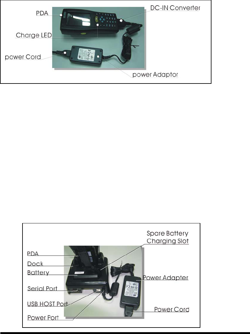
2.3.2 Charging the battery pack with Power Adapter
1. Plug in the DC-IN Converter to the PDA bottom connector
2. Connect the Power cord to the Power adapter
3. Plug in the connector of the power adapter with DC-IN Converter
4. Connect the power cord to a power source
Figure 2-8 Charging with power adapter
◆ When charging the battery pack, the Power LED on the PDA turns on Red.
◆ After the battery pack is fully charged, the Power LED turns to green.
2.3.3 Charging the battery pack with Single Cradle
a) Leave the battery pack inside of the PDA
1. Connect the Power cord to the Power adapter
2. Connect the power cord to a power source
3. Plug in the connector of the power adapter with Single Cradle
4. Insert the PDA into the Single Cradle
Figure 2-9 Charging with Single Cradle
P2-8
◆ When charging the battery pack, the Power LED on the PDA turns on Red. After
the battery pack is fully charged, the PDA Power LED turns to green.
b) Place the spare battery pack into the Single Cradle’s spare Battery charging slot
1. Connect the Power cord to the Power adapter
2. Connect the power cord to a power source
3. Plug in the connector of the power adapter with Single Cradle
4. Insert the Battery pack into the Single Cradle’s spare Battery slot
◆ When charging the Battery pack in the Single Cradle’s spare Battery slot, the
Single Cradle charging LED will turn on Red. After the Battery pack is fully
charged, this LED will turn to green
CAUTION: Please don’t remove the Battery pack too long from PDA after you
have already full-charged the Battery pack and backup battery pack and start
to use the PDA. Otherwise the data stored inside SDRAM memory will be lost.
Please also keep in mind power the PDA off if you want to change the main
Battery pack.
2.4 Handling the PDA
2.4.1 Starting the PDA
Press the Power key to turn on/off the PDA. If the PDA does not power on, perform a
cold boot. See 2-7 Resetting on page 2-XX.
CAUTION: When a battery is fully inserted in PDA for the first time, upon the
PDA’s first power up, the device boots and powers on automatically.
Figure 2-10
P2-9
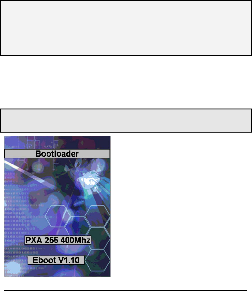
When the PDA is powered on for the first time,
it initializes its system. A splash screen (figure
2-10) appears for a short period of time
followed by the Wince.NET 4.2 window.
This section offers the basic procedures of
PDA using.

2.4.2 Power (and Backlight) on / off
To turn on the PDA
Press the Power/Backlight key briefly ( ). If the PDA does not power on, perform
the cold reset. See chapter 2.7.1.
As the PDA initializes its File system, the IT7000 splash screen displays for about 30
seconds followed by calibration screen. Every time you perform a cold reset, these
screens will also appear.
To turn off the PDA, just press the Power/Backlight key again. This action does not
actually turn off the PDA, it only turn the PDA into suspend mode. All running
applications remain as you left them, until you press the Power key again to resume
operation of the PDA
To Turn on/off the backlight
Press the Power / Backlight key briefly to turn on the PDA. And press the key again
briefly to turn off the PDA. The backlight is always on as the default. When the PDA
is ON, press the key longer, it will turn off the backlight. Press the Power / Backlight
key a little while again, it will turn on the backlight. Or just touch the screen or press
any key, it also can turn on the backlight again.
2.4.3: Calibration of the touch Screen Figure 2-11 Calibration
When you feel the touch screen function is poor or the operation does not match the
exact location it should be, please recalibrate the screen by using the stylus to enter
into the star bar --- Setting --- Stylus, to open the “Calibration” to recalibrate again.
P2-10
On the initial boot-up of the PDA, the
stylus calibration screen (Labele
d
Align Screen) opens. Use the stylus
to press and hold briefly on the cente
r
of each target as it moves around the
screen.
If necessary, adjust the backlight on
the PDA to make the screen readable.
(See below 2.4.4. Adjusting the
brightness).

2.4.4: Adjusting the brightness
The factory default for the brightness is in maximum status. You can adjust the
brightness to meet your environment and comfort as:
1) Become brighter: Press the <FN> key and then press on the right key of
Navigation key .
2) Become darker: Press the <FN> key and then press on the left key of
Navigation key .
3) The display will become dimmer automatically, if you do not perform any
operation for a specific period of time. This will help to save the battery power. You
can set up the specific period of time to see chapter 2.7 as reference.
2.4.5: To mute the Sound
To mute the sound, press the <FN> key and <Esc> key together to turn off and on of
the sound
2.4.6: Using the Stylus
The stylus is located next to CF cover or hand-strap on the left rear of the PDA as
illustrated in figure 2-3 PDA Back side view (in page 2-3). The stylus function is
same as the mouse on a PC. Use the stylus to:
1) Navigate the display, select menu item and open optional applications.
2) Tap the characters on soft keyboard panel
3) Hold the stylus on the screen and drag across the screen to select the list of multiple items.
CAUTION: Never use a pen, pencil, or other sharp object on the display to avoid any
unexpected damage of the touch screen.
P2-11
2.4.7: Using the Keypad
Figure 2-12 IT7000 Keypad
Table 2-2(A) Keypad List:
Key Main Function Fn+ Main Function Alpha+ Main Function
POWER ON/OFF
BarCode Start
Front Light
USER DEFINE
USER DEFINE
USER DEFINE
USER DEFINE
Right Backlight
Increase
P2-12
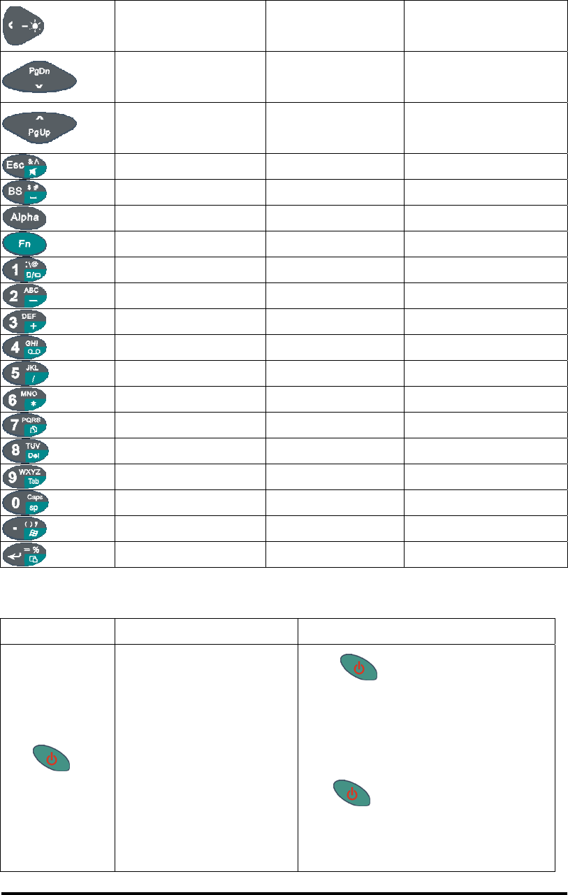
Table 2-2(B) Keypad List:
Left Backlight
Decrease
Down Page Down
Up Page Up
ESC Audio Mute & ^
Backspace ︼ $ #
Change to letters
Function change
1 Rotation : \ @
2 - A B C
3 + D E F
4 Record G H I
5 / J K L
6 * M N O
7 Copy P Q R S
8 Delete T U V
9 Tab W X Y Z
0 Space Caps
. START ( ) ,
Enter Paste % =
Table 2-3(A) Definition of main Function:
Key Main Function Definition
POWER ON/OFF or
Backlight ON/OFF
1. The key puts the terminal into and
wakes the terminal from suspend mode if this
key button isn't pressed more than two
seconds.
2. The key turns on/off the LED
backlight of LCM if this key button is pressed
more than two seconds.
P2-13
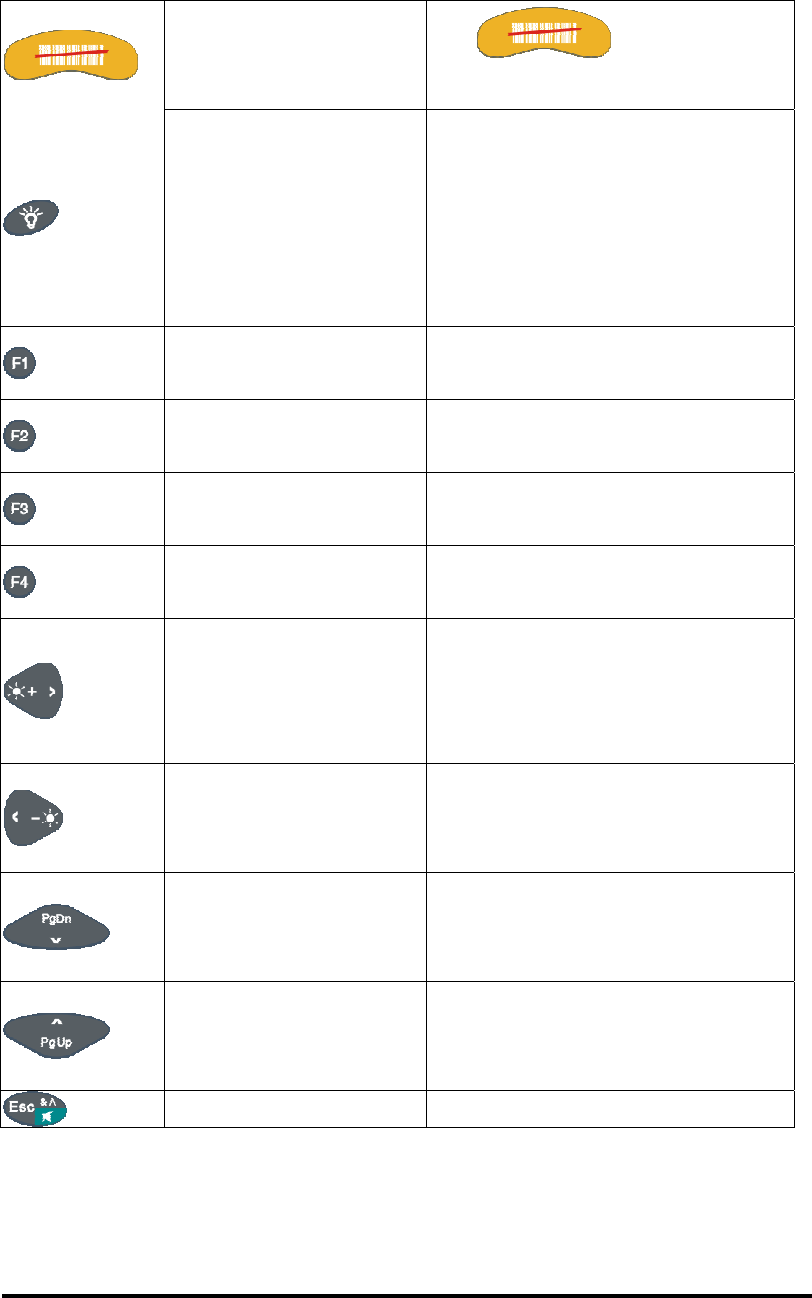
Table 2-3(B) Definition of main Function:
Bar Code Start The key activates the
scan function of IT7000.
Front Light
1.It turns on the “White LED"flash
light of IT7000 if this button is keeping
pressed.
2.The “White LED"flash light is off
immediately after this button is
depressed.
USER DEFINE Application key 1, User can define F1
function from setting.
USER DEFINE Application key 2, User can define F2
function from setting.
USER DEFINE Application key 3, User can define F3
function from setting.
USER DEFINE Application key 4, User can define F4
function from setting.
Right
Move the cursor one character to the
right. The cursor will move
continuously if button is pressed
continuously.
Left
Move the cursor one character to the
left. The cursor will move continuously
if button is pressed continuously.
Down
Move the cursor down one row or line
The cursor will move continuously if
button is pressed continuously.
Up
Move the cursor up one row or line
The cursor will move continuously if
button is pressed continuously.
ESC This key performs a cancel action
P2-14
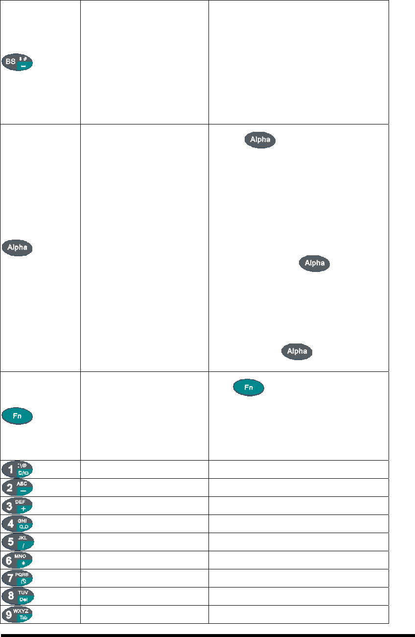
Table 2-3(C) Definition of main Function:
Backspace
“Backspace" key, it moves the
cursor back one space each time the
key is pressed. It deletes the previous
character each time it is pressed if you
are typing text. The cursor will move
continuously if button is pressed
continuously.
Change to letters
1. The key enables you to
toggle between the numeric and alpha
modes. Numeric mode is when you
type numbers with number keys. Alpha
mode is when you type letters with the
number keys.
2. When you press key, it
appears" Alpha “icon at the Task
bar to indicate Alpha mode is enabled.
The keypad stays in the alpha mode
until you press key again.
Function change
The key is used in
combination with other keys to type
special characters and perform system
functions.
1 Number key “1"
2 Number key “2"
3 Number key “3"
4 Number key “4"
5 Number key “5"
6 Number key “6"
7 Number key “7"
8 Number key “8"
9 Number key “9"
P2-15
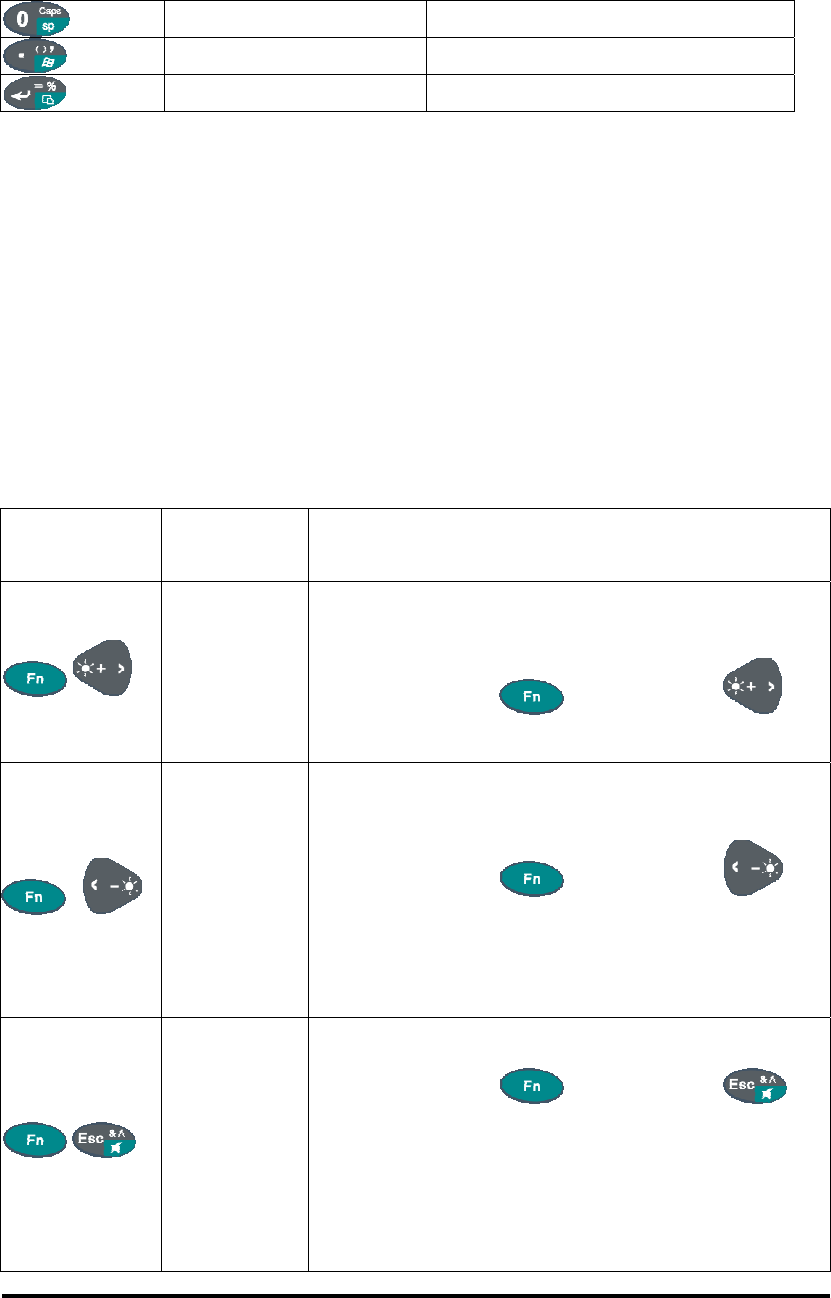
Table 2-3(D) Definition of main Function
0 Number key “0"
. Point key
Enter This key confirms data entry
2.4.7.1: Special Function by “Fn” + main Function:
1. The “Fn” key is used in combination with other keys to type special characters and
perform system functions.
2. Each key modifies only the next key pressed. For example to change display from
portrait type to landscape type(1) First, press “Fn” key, and then press “1” key.
If you change display from landscape type to portrait type, you must press “Fn”
key, and then press “1” key again.
Table 2-4(A) Special Function key define
Key sequence
Fn+ Main
Function Definition
, Backlight increase
1. Increase the LED backlight brightness of display
screen(Lighter)
2. You must press key, then press key
to increase backlight brightness each time.
,
Backlight
decrease
1. Decrease the LED backlight brightness of display
screen( darker)
2. You must press key, then press key
to decrease backlight brightness each time.
, Audio Mute
1. Toggle The audio mute/on
2. You must press key, then press
key to enable audio mute or turn on audio function
each time.
3. There are different icons to show the status“ Audio
mute"& “Audio Enabled "at the TASK bar.
P2-16
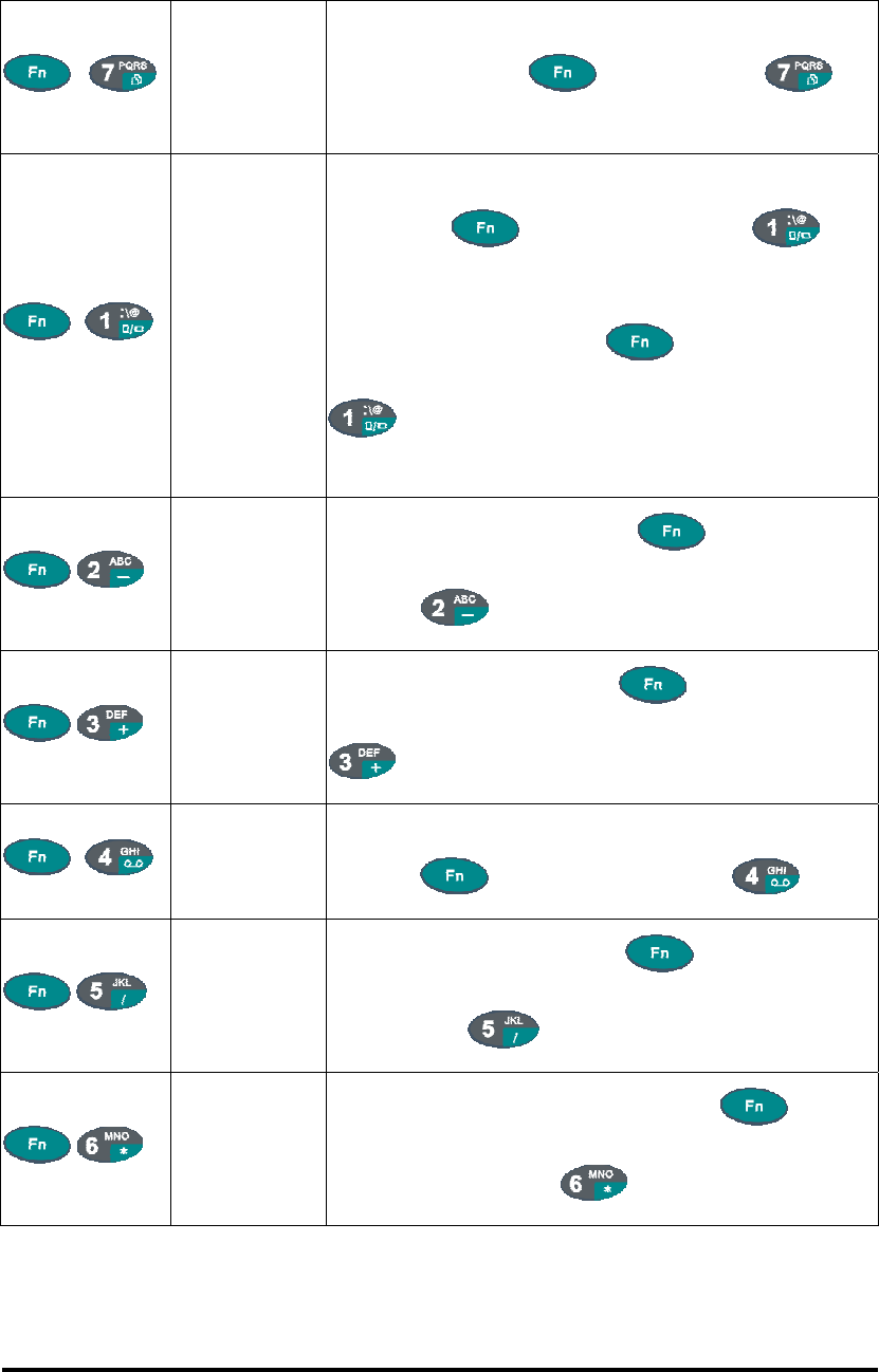
Table 2-4(B) Special Function key define
, COPY
1. Copy action
2. You must press key, then press
key to do“COPY "action each time.
, Rotation
If you change display from portrait type to landscape type,
please press key first, and then press key.
Otherwise, if you change display from landscape type to
portrait type, you must press key, and then press
key again.
, -
Enter a minus sign by pressing key, then
pressing key
, +
Enter a plus sign by pressing key, then pressing
key
, Record
Enter “Record" application and do record action by
pressing key first, then pressing key.
, /
Enter a backslash by pressing key first, and
then pressing key.
, *
Enter an asterisk“*"sign by pressing key
first, and then pressing key.
P2-17
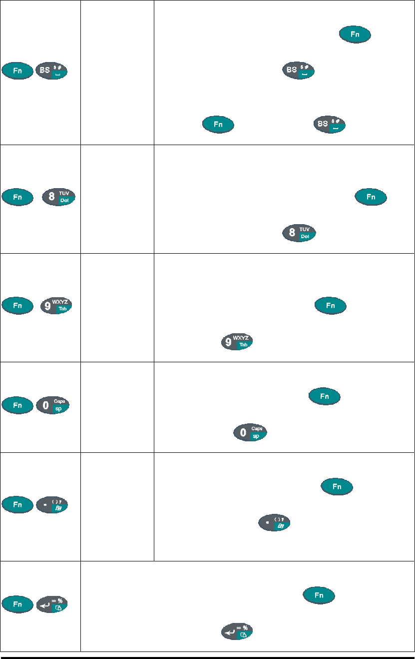
Table 2-4(D) Special Function key define
, ︼
1. Produces a space
2. To enable this function by pressing key
first, and then pressing key.
3. You want to disable this function, you still need to
press key, then press key again.
, Delete
1. The “Delete “ function delete the next character
forward each time
2. To do “Delete"function by pressing key
first, and then pressing key each time.
, Tab
1. The “Tab “function is to move the cursor to the
next tab stop or the next control (on a form)
2. To do this function by pressing key first, and
then pressing key each time.
, Space
1. The “Space "function is to move the cursor one s
p
ace.
2. To do this function by pressing key first, and
then pressing key each time.
, Start Menu
1. It displays the Start menu
2. To do this function by pressing key first,
and then pressing key each time.
, Paste
It is to do “Paste "function.
To do this function by pressing key first, and
then pressing key each time.
P2-18
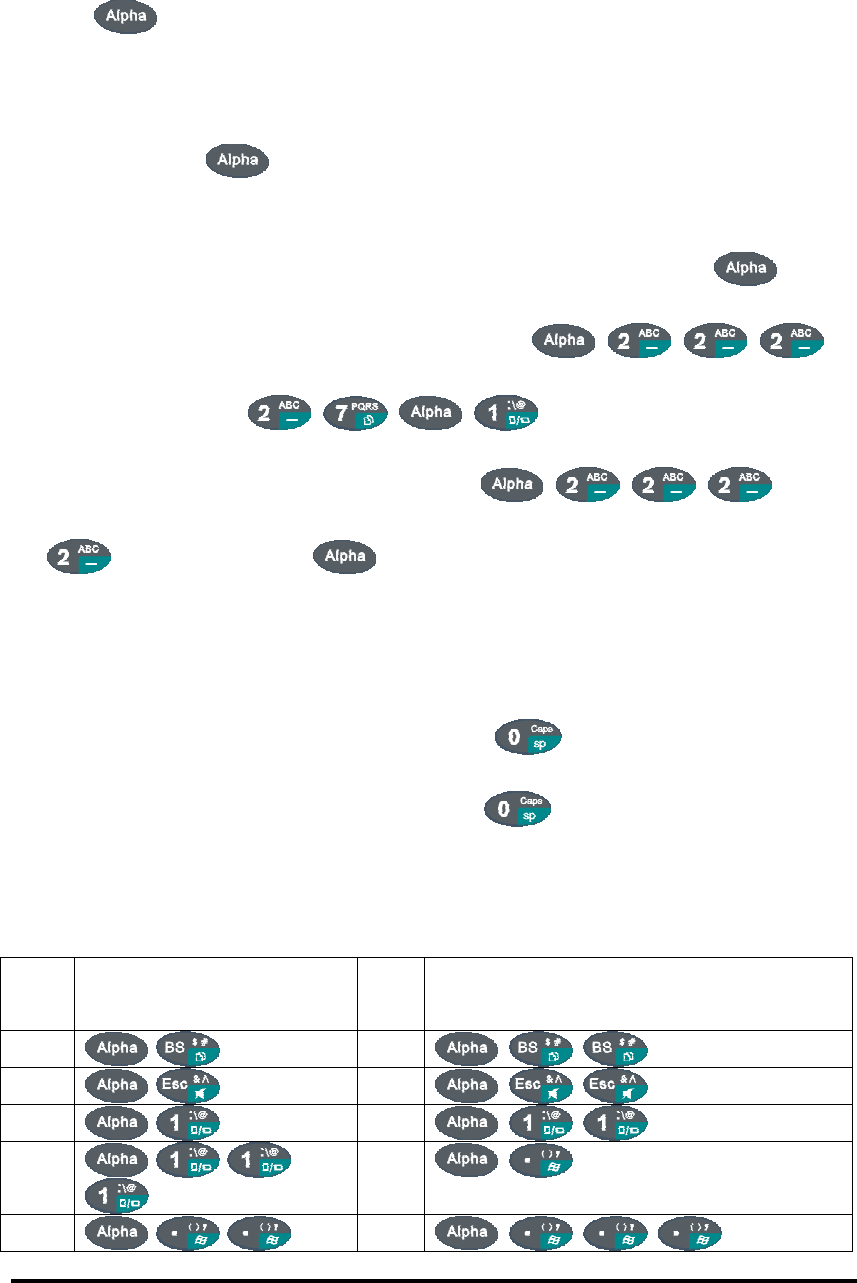
2.4.7.2: Alpha plane keys by “Apha” + main Function:
1. The key enables you to toggle between the numeric and alpha modes.
Numeric mode is when you type numbers with number keys. Alpha mode is when you
type letters with the number keys.
2. When you press key, it appears “ Alpha "icon at the Task bar to indicate
Alpha mode is enabled. It means Alpha mode is disabled if there isn't “Alpha
“ icon at Task bar. The keypad stays in the alpha mode until you press key
again. For a example to type “ cap1“ word, press
< wait 0.5 seconds >
3. If you want to type a lowercase “ c “, press (The
key three times, the key is needed if it's the first alpha character
keying in. ). If a letter that is on the same key as the last letter entered, wait two
seconds after you pressed the last key, then you can enter the correct series of
keystrokes to create the next letter.
4. While you are in the Alpha mode and you press key to initial the CAPS mode,
you will render a CAPS LOCK until you press key again. Once you are in
CAPS mode, you stay in CAPS until it is pressed again.
5. It appears “CAPS" icon at TASK bar during CAPS mode.
Table 2-5(A) Alpha + Numeric keys define
To
enter
Press the Keys To
enter
Press the Keys
$ #
& Λ
: \
@
(
) ,
P2-19
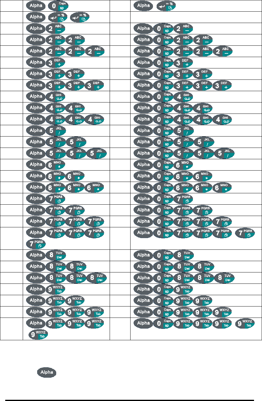
Table 2-5(B) Alpha + Numeric keys define
Caps =
%
a A
b B
c C
d D
e E
f F
g G
h H
i I
j J
k K
l L
m M
n N
o O
p P
q Q
r R
s
S
t T
u U
v V
w W
x X
y Y
z
Z
Note:
1. The key isn’t needed to key in if the character isn’t the first alpha
character being keyed in.
P2-20
2. The keys are not needed to key in if it isn’t the first capital alpha
character being keyed in.
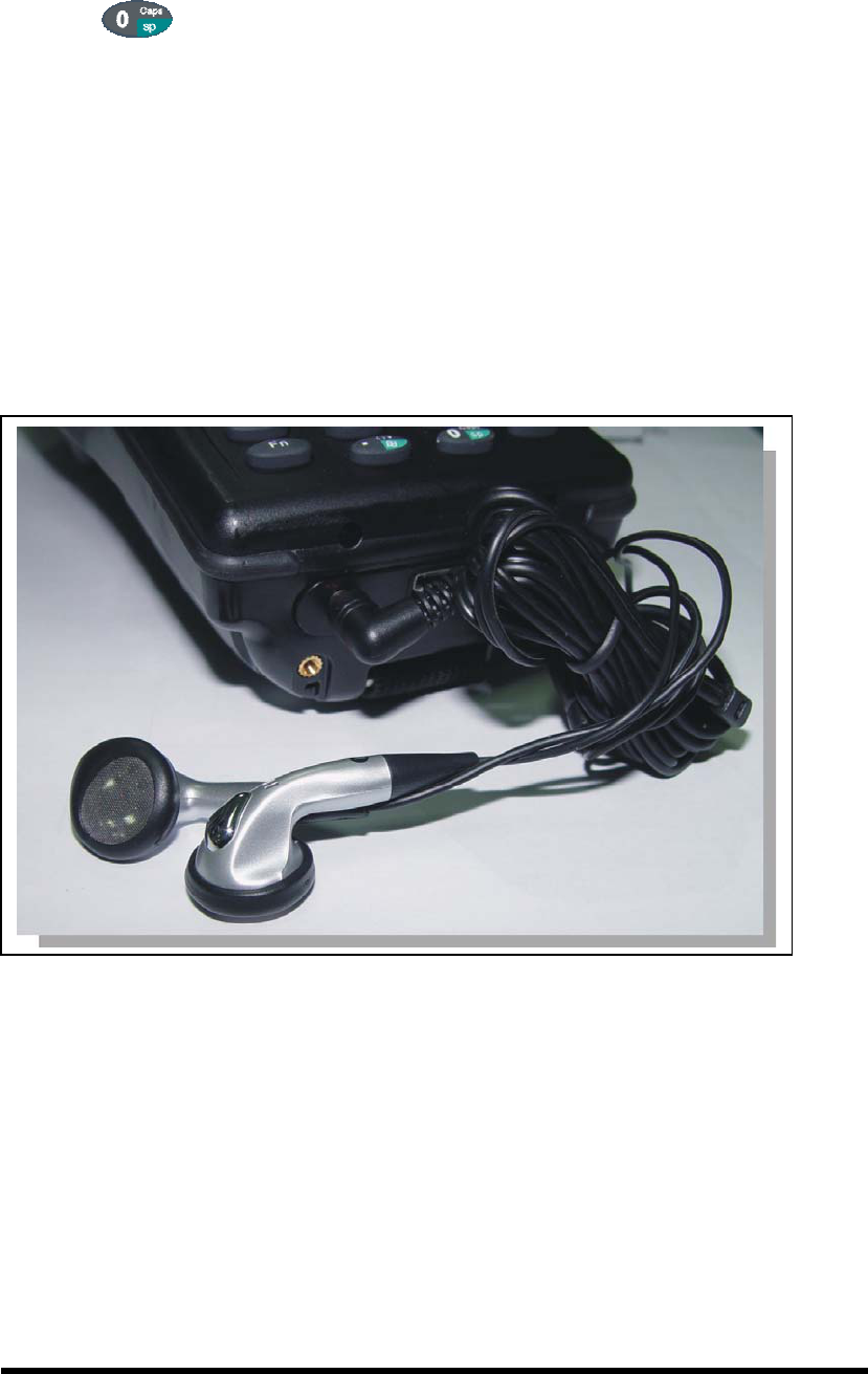
2.4.8: Using the Ear/Microphone
Connect Ear/Microphone to PDA earphone jack. The PDA is not built in microphone,
if you like to record the voice, you have to use Ear/Microphone.
Figure 2-13 Ear/Microphone
2.5: Navigating the Display
2.5.1: Setting the Date and Time
P2-21
2.5: Navigating the Display
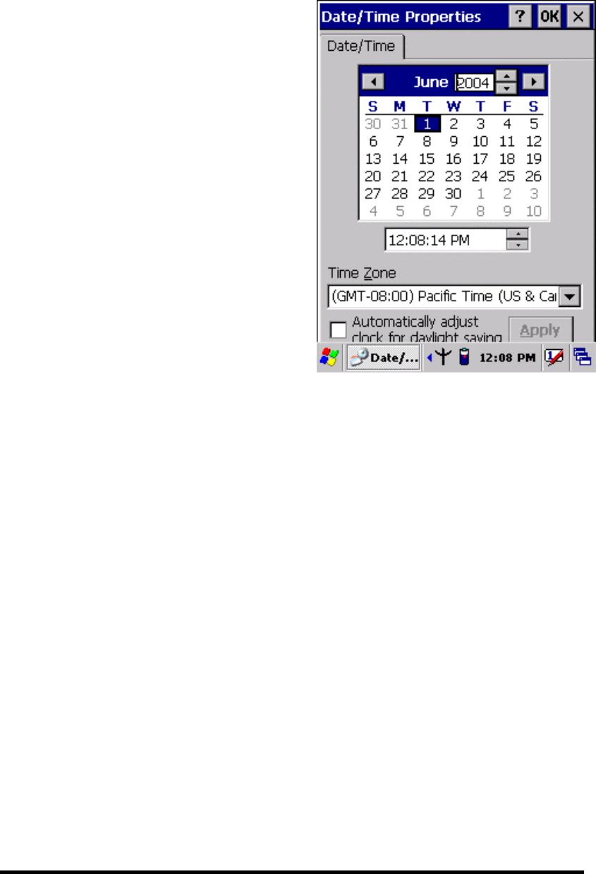
2.5.1: Setting Time and Date:
Figure 2-14 Date/Time properties
4. To change the time, select the hour, minute, seconds, or AM/PM and select the up
arrow to increase the value; select /tape the down arrow to decrease the value. Or
you can type a new value in the field.
5. Select your correct time zone from the pull-down list.
6. To automatically adjust the clock for Daylight Saving Time, enable the checkbox
at the bottom of the screen.
7. Select Apply to make save your changes [and make additional modifications] or
select OK to exit the Date/Time settings.
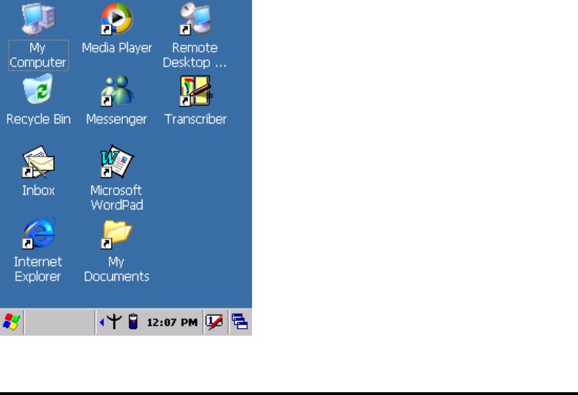
2.5.2: Entering the Data
To select and open programs, select Start > Programs from the task bar to open a list
of available programs. Or if the program has a icon on the desktop, double-tap to open
it.
There are several ways to enter data on the PDA once in an application:
Use the keypad to enter alpha-numeric characters, Refer to “2.4.7 Using the
keypad” on page 2-12.
Use the stylus on the touch screen on page 2-6 for more information on using .
P2-22
In the Date/Time options, you can
change the year, month, date, time, time
zone, or select automatic adjust for
Daylight Saving Time. To set or change
the date and time:
1. Select Start > Settings > Control
Panel > Date/Time
2. Select the month to open a pull-down
list of months or press the arrow
buttons to either side of the month to
increase or decrease the month.
3. To change the year, select the year or
open a numeric dial. Select the up
arrow to increase the value; select the
down arrow to decrease the value. Or
you can type a new value in the field.
the stylus.
Select text in the same way you select the text on a PC. Use the stylus to
highlight the desired text by dragging the stylus across the desired text,
double-tapping to select one word and triple-rapping to select an entire
line/paragraph. Refer to “2.5 Navigating the Display” starting on page 2-22
Use the soft input panel (digital keyboard) with the stylus. Refer to “2.5.5 The
Soft Keypad” on page 2-23.
Use the bar code scanning to enter data. Press the trigger or “Bar Code Start
“ key to initiate a scan. The scanned data will enter the current application’s open
file. Refer to :2.5.7 Scanning Barcode” starting on page 2-24 for more
information on using a scanner.
For more information on factory installed applications, Refer to Chapter 4 “ Software
Programs”.
2.5.3: The Command Bar:
Use the Command bar at top of the screen to perform tasks in programs, such a
opening a file, or editing a file.
2.5.4: The Task Bar:
The Task bar at the bottom of the screen displays the icon, an icon for the active
program, the current time, and system icons for utilities loaded in memory. The Task
bar includes menu names, buttons, and the keyboard icon, which opens and closes the
soft input panel (SIP). The Task bar allows you to select and close programs. Refer to
Figure 2-15 to view the Task bar.
Figure 2-15 Task Bar
P2-23
2.5.5: The Soft Keypad
In applications that accept keypad input, the soft input panel (SIP) can be used to
enter data using the stylus. The SIP is digital, QWERTY-style keyboard.
To open the SIP, tap the keyboard icon to open the menu and select Hide Input
Panel to close the keyboard.
Use the stylus to select letters, numbers, or symbols from the Soft Input Panel for the
current application.
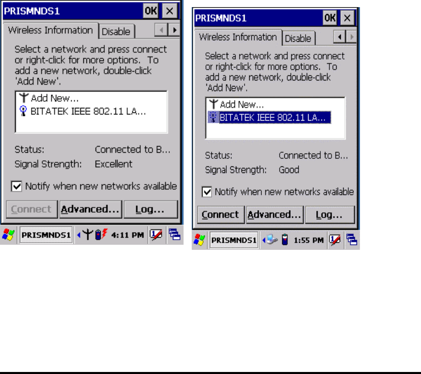
2.5.6: Initiating a Network Connection
To tap the icon at Task bar, then a Wireless LAN screen “PRISMNDS1”(Figure
2-16-1), select page “Wireless Information”. There is a list of Wireless access points.
Select one by double-clicking the access point you want. Or double-click “Add New
“ to add a new access point.
To Click “Connect” icon to connect WLAN with Access point.( Figure 2-16-2)
To select page “ Disable” to disable WLAN to save power consumption. ( Figure
2-16-3 & Figure 2-16-4)
Figure 2-16-1 Figure 2-16-2
P2-24
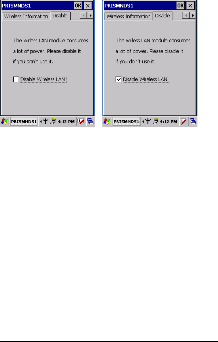
Figure 2-16-3 Figure 2-16-4
2.5.7: Scanning Barcode:
To use the scanning function, complete the following steps:
1. If you have not already done so, remove the protective plastic film before using
devices equipped with a laser scanner.
2. Select Start > Setting > Control Panel > Barcode setting, set/ enable / disable
the value of each item.
3. Run the WordPad software program
4. Aim the scanning beam at the center of bar code.
Position the device close to bar code when scanning
Position at a distance when scanning lager bar codes.
The scanner is disabled after you release the key or after five seconds.
5. Press the Right/left/central scan key. The scanner scans as long as you hold the
key or for five seconds.
6. Upon reading a bar code, the red LED indicator comes on until the trigger is
release or five seconds. The green LED and the beep tone indicate a good read.
P2-25
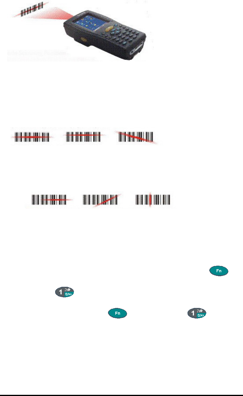
7.Barcode Scanning Position
This device can read from 40 to 300mm distance.
1) Position the laser scanner close to the barcode when scanning small
barcodes. And position it is a distance from the barcode when scanning
large barcodes
2) The reader can be detected by a red beam.
8. Bad Scanning Position
1) Make sure that the bars enter the laser beam when scanning large
barcodes.
2) Scanning operations may fail if the laser beam position as below.
Note: this product scans using laser light. Never look directly into the laser light
or shine the laser light into the eyes.
2.5.8. Rotating the Screen:
If you change display from portrait type to landscape type, please press key
first, and then press key. Otherwise, if you change display from landscape
type to portrait type, you must press key, and then press key again.
2.5.9. Help:
To tap “?” to get help information for each program.
P2-26

2.6 Power management
2.6.1 Suspend Mode
The PDA will go into a suspend mode when it is idle for a period of time. The idle
duration can be customized using the Power control panel (refer to Figure “Schemes
Tab”) Suspend mode works and looks just like you have turned the unit off. Press the
key to suspend the PDA, Press the key again for the PDA to resume its
Previous state.
Use the Battery power control panel to set the duration to switch state to Suspend
mode when system using battery power. This will save battery power when PDA is
not in use.
P2-27

Schemes Tab
Suspending:
The following conditions will suspend:
Press <Power> key while the unit is on.
The duration timer of item “ Switch state to Suspend “ expires, which indicates
that there has been no use for a specified of time.
The battery pack is completely discharged.
2.6.2. Resuming:
Use one of following methods to resume(wake up the PDA):
Press <Power> key to suspend or resume ( wake up).
Put the PDA into a dock.
Press the <Scan> key to wake up the PDA.
When a battery pack completely discharges while the unit is in suspend mode,
the PDA remains suspended until discharged battery condition is corrected.
2.7: Resetting the PDA
2.7.1: Software (Warm) Reset
A warm reset is a transition from the on, idle, or suspend power state that close all
applications, clears the working RAM, but preserves the file system.
P2-28

Reason to Warm Reset: If a application “hangs”, initiate a warm reset to terminate
the application only.
Procedure to Warm Reset: To initialize a warm reset, press and hold the <Reset>
key.
After Warm Reset:
The desktop appears with the application shortcuts on the screen.
The custom settings in the registry are persistent.
The RF Network PC card if present, connects to the network system.
2.7.2: Cold Reset
1) You can use Cold Reset to initiate device if WINCE.NET OS lock up or Warm
Reset still can’t work
2) To perform Cold Reset, use stylus to press “ Reset” key and press “Power” key
simultaneously.
3) Device will initiate boot up after Cold Reset.
CAUTION: Only use stylus to press the Reset key. Try warm reset before you
initiate Cold Reset. All applications will be Closed and working RAM and all
files will be cleared if you initiate the Cold Reset. It’s better usually to back up
your files to Flash ROM, Flash Card or PC.
P2-29
Chapter 3
Setting
3.1 Introduction
To view available options for PDA’s setting, tap Start > Setting. Then, there are
three items inside Setting: “Control Panel”, “Network and Dial-up Connection
“and “Task and Start Menu”.
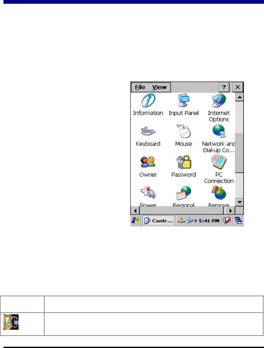
3.2 Control Panel
Figure 3-1 Control Panel
3.2.1 Backup Restore
Table 3-1 Backup Restore (A)
ICON ITEM & FUNCTION
1. Backup – You can backup registry or system to Flash disk or
inserted (Figure 3-2-1)
P3-1
To view the Control Panel and
settings you can modify by tapping
Start > Setting > Control
Panel.( Figure 3-2)

Table 3-1 Backup Restore (B)
Backup storage: Can storage backup data into (1) Disk on Chip (2)
CF Card (3) SD Card ( Figure 3-2-2)
Backup: You can select backup data region only for Registry
region or all the Full system region (Figure 3-2-2)
It also shows available Flash Disk size, Selected
User Data size that are already backup, and Last
backup date. ( Figure 3-2-2)
“Backup Now” icon: Tap the icon “ Backup Now” to start to backup
data. And a Warming icon will pop up (Figure 3-2-3).
Please tap “OK” to continue backup procedure if you still
want to proceed it. This procedure will keep a few minutes,
and a “Message” icon shows “Backup system OK! “.
Please tap”OK” to finish this procedure.
“Delete Backup File” icon: You can tap “Delete Backup File” to
delete all backup data. There is also a “Warning” icon to
ask you ”Are you sure to delete backup file”. Tap “OK”
to continue deleting backup files
(Figure 3-2-2)
Restore: You can restore user data from Flash disk
or inserted memory card.(Figure 3-2-4)
Restore storage: Restore data from (1) Disk on Chip (2) CF
Card (3) SD Card (Figure 3-2-5)
“Restore Now” icon: tap “Restore Now” icon to start to restore
data. And a “Warning” icon shows
warning message. Tap “Ok” to continue
this procedure. There is Message showing
on the screen “ Restore system finished,
please reset the system to take effect. Do
you want to proceed?” Please tap the
“OK” icon to warm reset the system and
start from a situation with the restored
environment.
P3-2
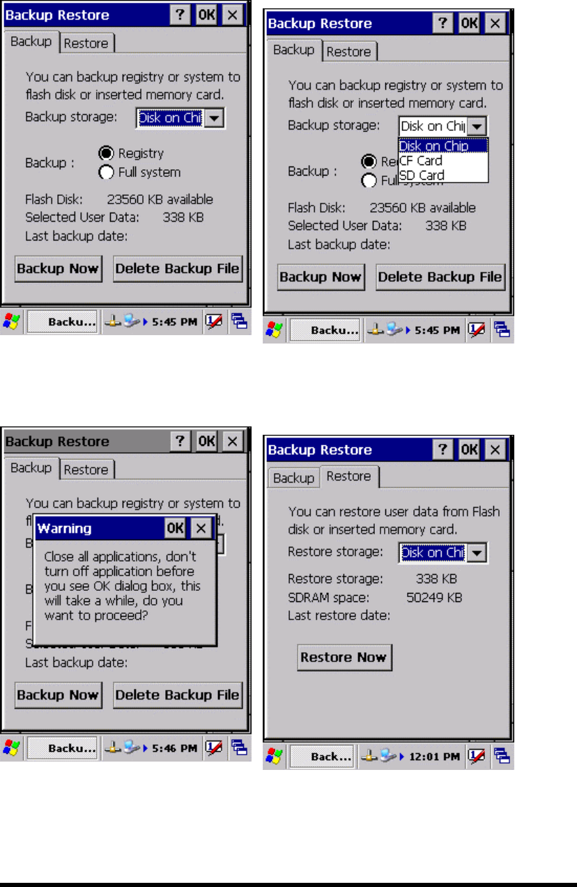
Figure 3-2-1 Figure 3-2-2
Figure 3-2-3 Figure 3-2-4
P3-3
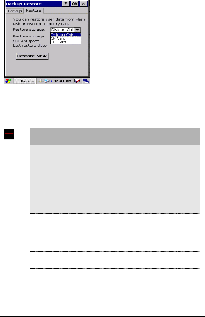
Figure 3-2-5
3.2.2 Bar Code Setting
Table 3-2(A)
There are three Tabs for scanner configuration setting: “BarCode”,
“Detail” and “Misc.”.
“BarCode” Tab(Figure 3-3-1 & Figure 3-3-2): Select the bar code
symbologies you plan to scan from the list. Tap to enable/disable the
desired symbologies.
Please note that it’s available barcode item with black words for built-in
engine, and it’s not available with grey words.
“Symbologies” Tab(Figure 3-3-3): Select the desired bar code
symbology from the pull-down list and complete the fields.
Please see 3.2.3 Symbologies List for more detail information of each Bar Code.
Field Name Function/Operation
Symbology List Select the bar code symbology from pull-down list
Enable Tap/Enable this checkbox to enable the selected bar
code symbology.
Format Two kinds of format can be selectable: “Standard” &
“ Full ASCII”
BarCode
Setting
Length
Min:2-80
Max:2-80
Not all symbologies have this option nabled.
Set the minimum and maximum lengths from
the up-down list in “Min” and “Max” items.
If the numbers are the same, acceptable bar
codes will only be that length.
P3-4

Table 3-2(B)
“Symbologies” Tab(Figure 3-3-3): Select the desired bar code
symbology from the pull-down list and complete the fields.
Please see 3.2.3 Symbologies List for more detail information of each Bar Code.
Field Name Function/Operation
Fixed Length
The length can be
set from 2 to 80
After the selected bar code is enabled, and the three
kinds of length is filled inside these three blank
items. Then, Only the selected bar code with one of
these three kinds of length can be showed the
customer’s application program.
Transmit Transmit the bar code by adding selected type(s) of
error checking protocol
Verify Enable/Disable the verification with Checksum.
“Options” Tab ( Figure3-3-4)
Field Name Function/Operation
Trigger
timeout(sec)
Select a trigger timeout duration(in seconds) from
this pull-down list.(3 sec ~10sec)
Keybd Message Select from “Type writing” and “Copy & paste”.
Select a method based upon the bar code scanning
application you will use.
Termination
Message
Select the desired termination code from the
pull-down list.<None, CRLF, Space, tab>
Beep after data
collect
Select the numbers of beep tone when scanning.
< 0,1,2 >
Auto Scan Select “Disable” to disable the auto scan
function.
Select/Enable the auto scan duration(in
seconds) from this pull-down list.
< 1,2,3,4,5>
Prefix Type the desired label prefix in this text
box
Label
Suffix Type the desired label suffix in this text
box
BarCode
Setting
Default Tap this tab to return back to the default value for
“Options” applet.
P3-5
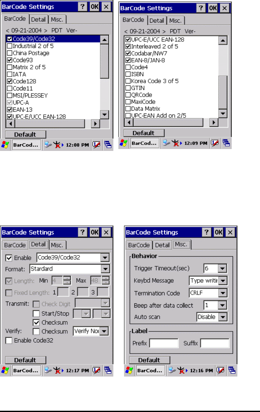
Figure 3-3-1 Figure 3-3-2
Figure 3-3-3 Figure 3-3-4
P3-6
3.2.3 Symbologies List
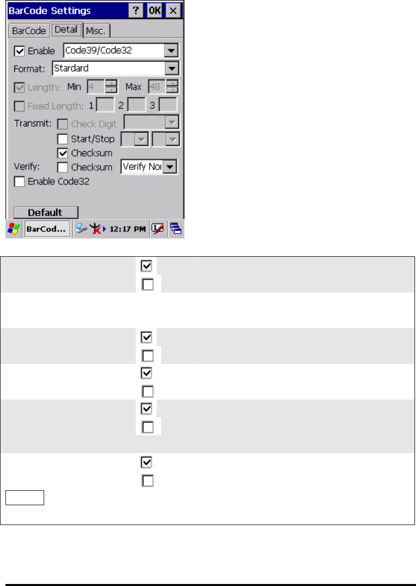
3.2.3.1 Code39/Code32:
□ Enable
Enable/Disable Code39
Format Standard
Full ASCII
Standard 43 Characters
Full ASCII character
□ Start/Stop
Transmit
Not transmit
□ Checksum
Checksum transmit
Checksum doesn’t transmit
Ver ify
□ Checksum
One of two kinds of verification, “Verify
Strick” or “ Verify Normal” can be
selected from the pull-down list.
□ Enable Code32
Enable Code32
Disable Code32
Default Tap the “Default” tab to return back to
default setting
P3-7
Code39 is a discrete, self-checking,
variable length symbology. The character
set is Uppercase A-Z, 0-9, dollar sign “$”,
p
eriod “.”, slash“/”, percent“%”,
space“ “, plus “+”, minus“-“.

3.2.3.2 Industrial 2 of 5
P3-8
□ Enable
Enable Industrial 2 of 5
Disable Industrial 2 of 5
□ Length
Min Length can be set from 2 to 48
Max Length can be set from 2 to 48
□ Fixed Length
Fixed Length 1 2-48
Fixed Length 2 2-48
Fixed Length 3 2-48
□ Check Digit
Check Digit transmit
Check Digit doesn’t transmit
Ver ify
□ Checksum
Enabled
Disabled
Default Tap the “Default” tab to return back to
default setting

3.2.3.3 China Postage
P3-9
□ Enable
Enable China Postage
Disable China Postage
□ Length
Min Length can be set from 2 to 80
Max Length can be set from 2 to 80
□ Fixed Length
Fixed Length 1 2-80
Fixed Length 2 2-80
Fixed Length 3 2-80
□ Check Digit
Check Digit transmit
Check Digit doesn’t transmit
Ver ify
□ Checksum
Enabled
Disabled
Default Tap the “Default” tab to return back to
default setting
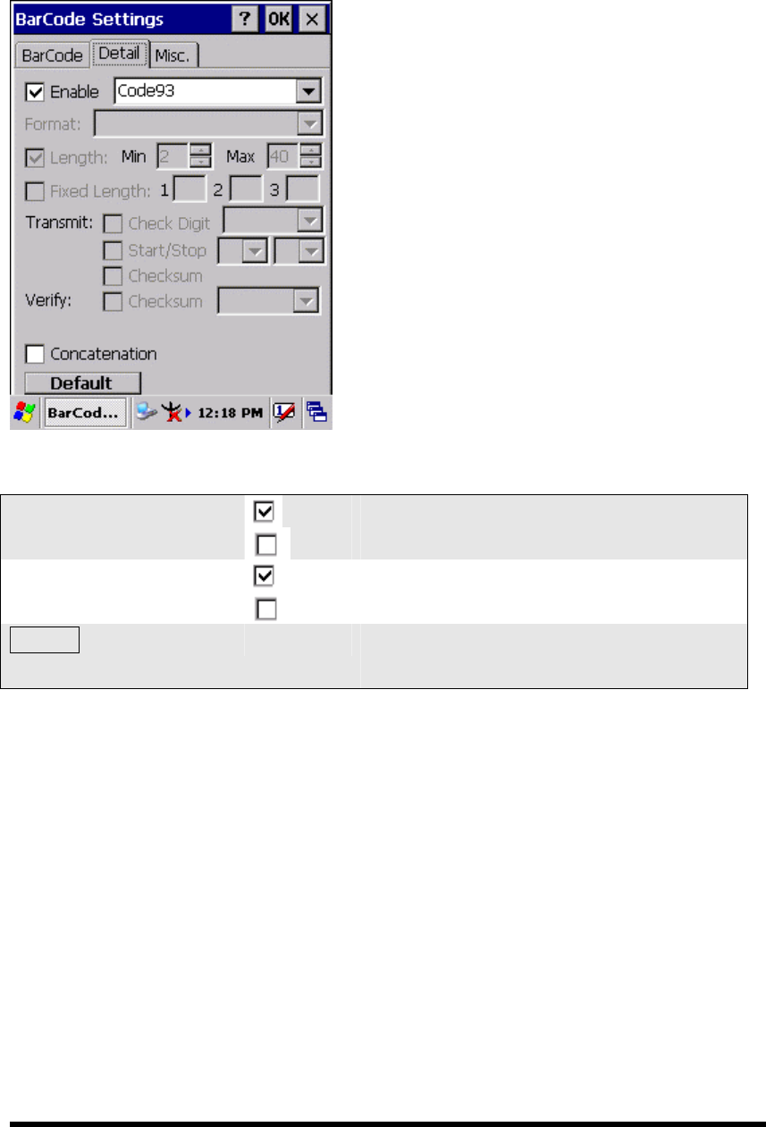
3.2.3.4 Code93
P3-10
□ Enable
Enable Code93
Disable Code93
□ Concatenation
Enable Concatenation
Disable Concatenation
Default Tap the “Default” tab to return back to
default setting
Code93 is a variable length, continuous
symbology that uses four element
widths.
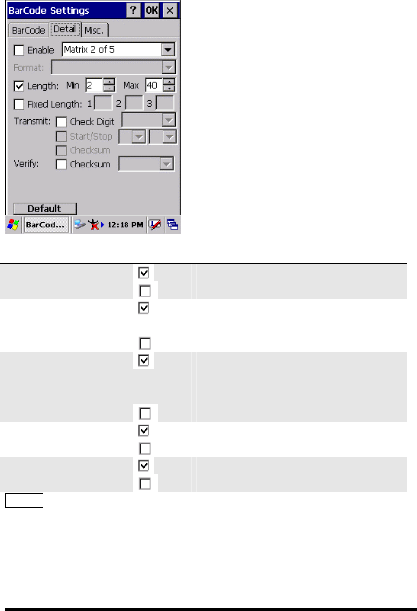
3.2.3.5 Matrix 2 of 5
P3-11
□ Enable
Enable Matrix 2 of 5
Disable Matrix 2 of 5
□ Length
Min Length can be set from 2 to 80
Max Length can be set from 2 to 80
□ Fixed Length
Fixed Length 1 2-80
Fixed Length 2 2-80
Fixed Length 3 2-80
□ Check Digit
Check Digit transmit
Check Digit doesn’t transmit
Ver ify
□ Checksum
Enabled
Disabled
Default Tap the “Default” tab to return back to
default setting

3.2.3.6 IATA
P3-12
□ Enable
Enable IATA
Disable IATA
Default Tap the “Default” tab to return back to
default setting

3.2.3.7 Code128
P3-13
□ Enable
Enable Code128
Disable Code128
Default Tap the “Default” tab to return back to
default setting
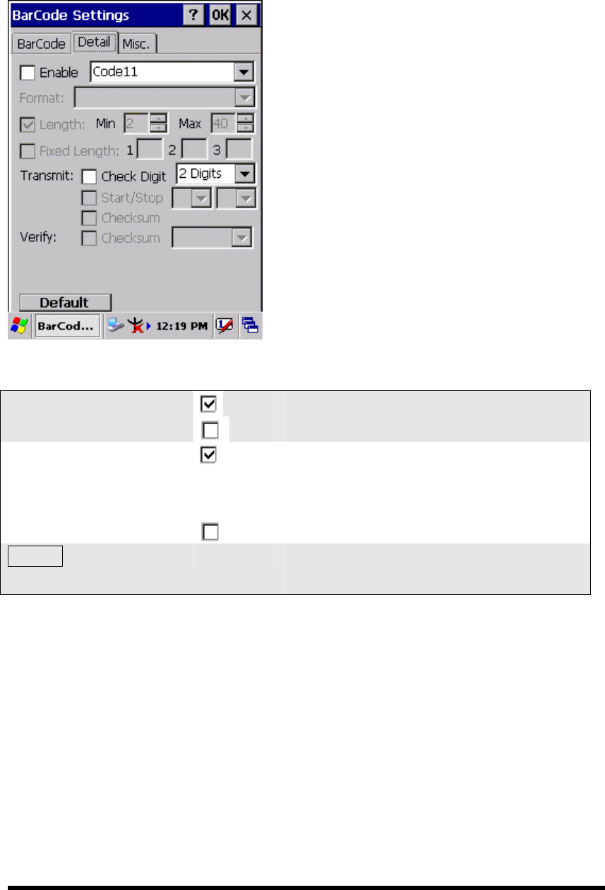
3.2.3.7 Code11
P3-14
□ Enable
Enable Code11
Disable Code11
□ Check Digit
Check Digit Transmit
Check digit verification can select “ 1
Digit” or “2 Digits”
Check Digit doesn’t transmit
Default Tap the “Default” tab to return back to
default setting
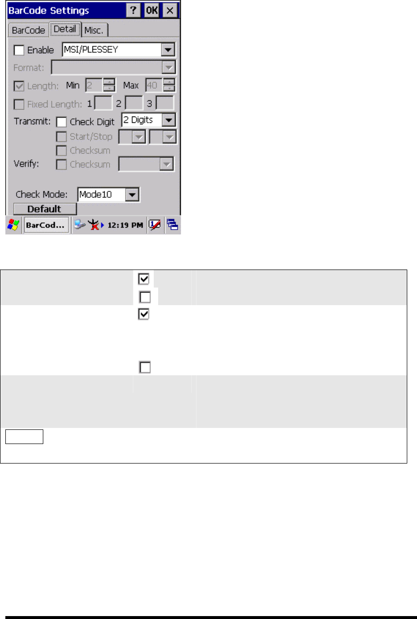
3.2.3.8 MSI/PLESSEY
P3-15
□ Enable
Enable MSI/PLESSEY
Disable MSI/PLESSEY
□ Check Digit
Check Digit transmit
Check digit verification can select “ 1
Digit” or “2 Digits”
Check Digit doesn’t transmit
Check Mode One of “Mode10”, “Mode10-10” and
“Mode11-10” can be selected from the
pull-down list.
Default Tap the “Default” tab to return back to
default setting
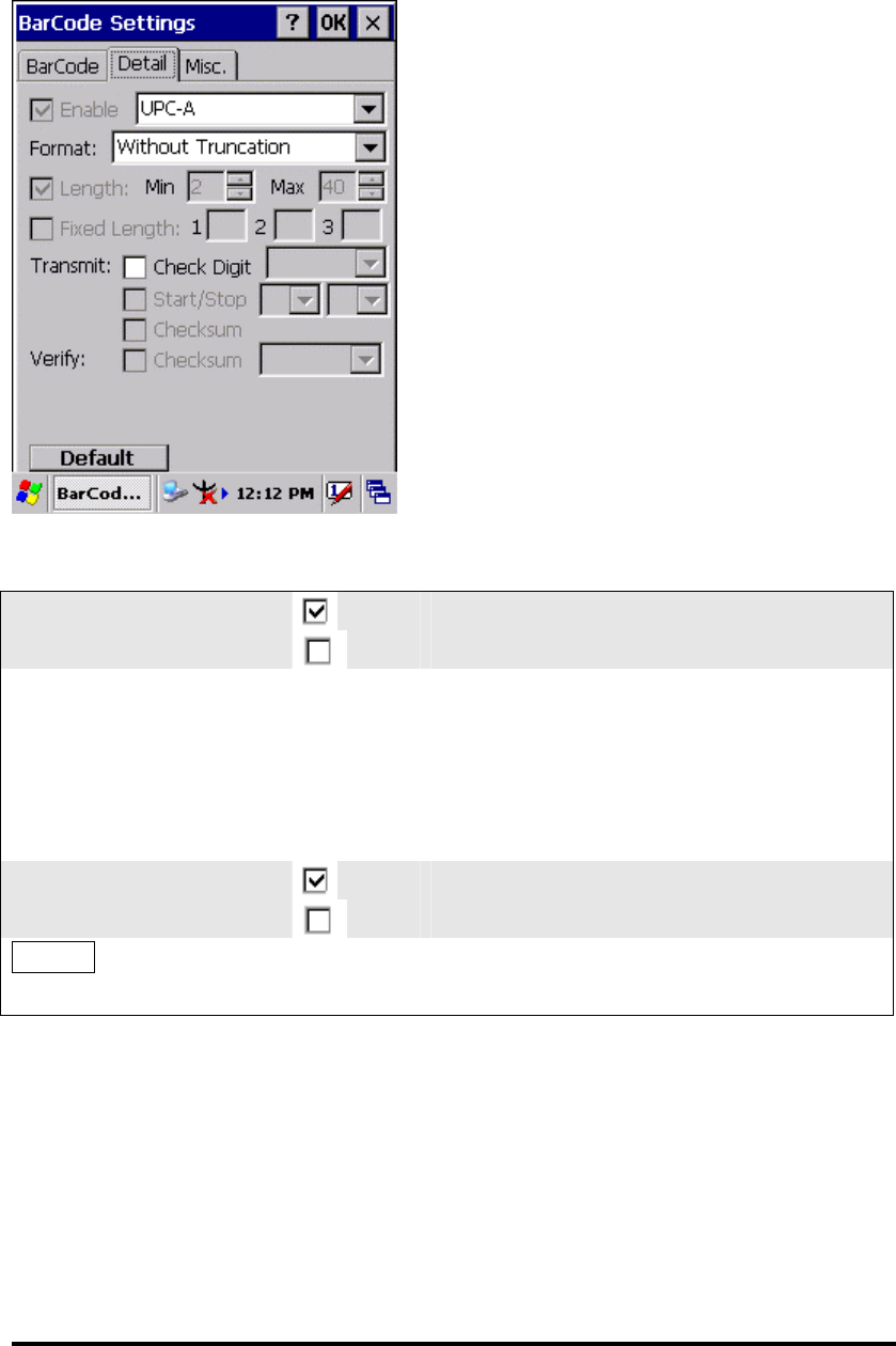
3.2.3.9 UPC-A
P3-16
□ Enable
Enable UPC-A
Disable UPC-A
Format Only one of the “Without Truncation”,
“Truncate Leading Zero”, “Truncate
Leading Digit” and “Truncate Leading
Zero and Digit” can be selected from the
pull-down list.
Check Digit
Check Digit transmit
Check Digit doesn’t transmit
Default Tap the “Default” tab to return back to
default setting
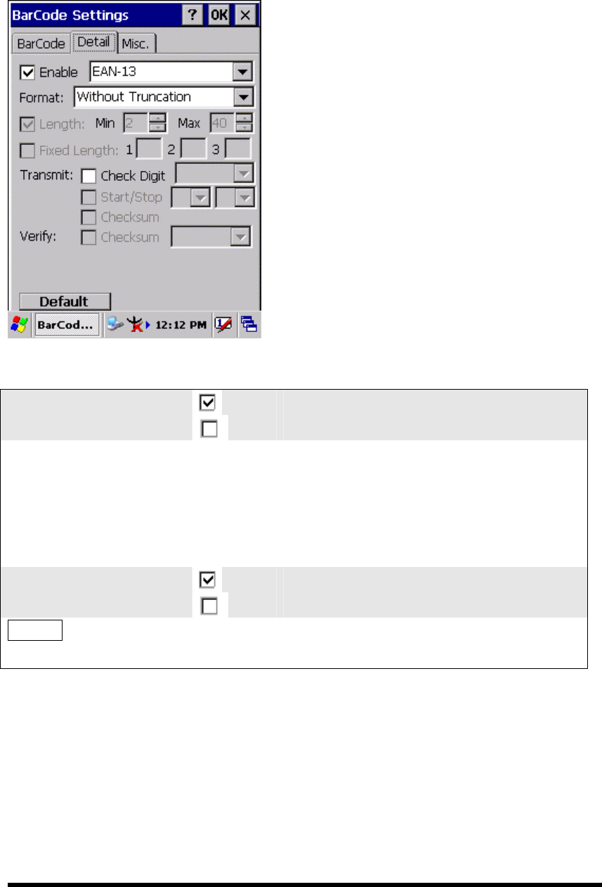
3.2.3.10 EAN-13
P3-17
□ Enable
Enable EAN-13
Disable EAN-13
Format Only one of the “Without Truncation”,
“Truncate Leading Zero”, “Truncate
Leading Digit” and “Truncate Leading
Zero and Digit” can be selected from the
pull-down list.
Check Digit
Check Digit transmit
Check Digit doesn’t transmit
Default Tap the “Default” tab to return back to
default setting
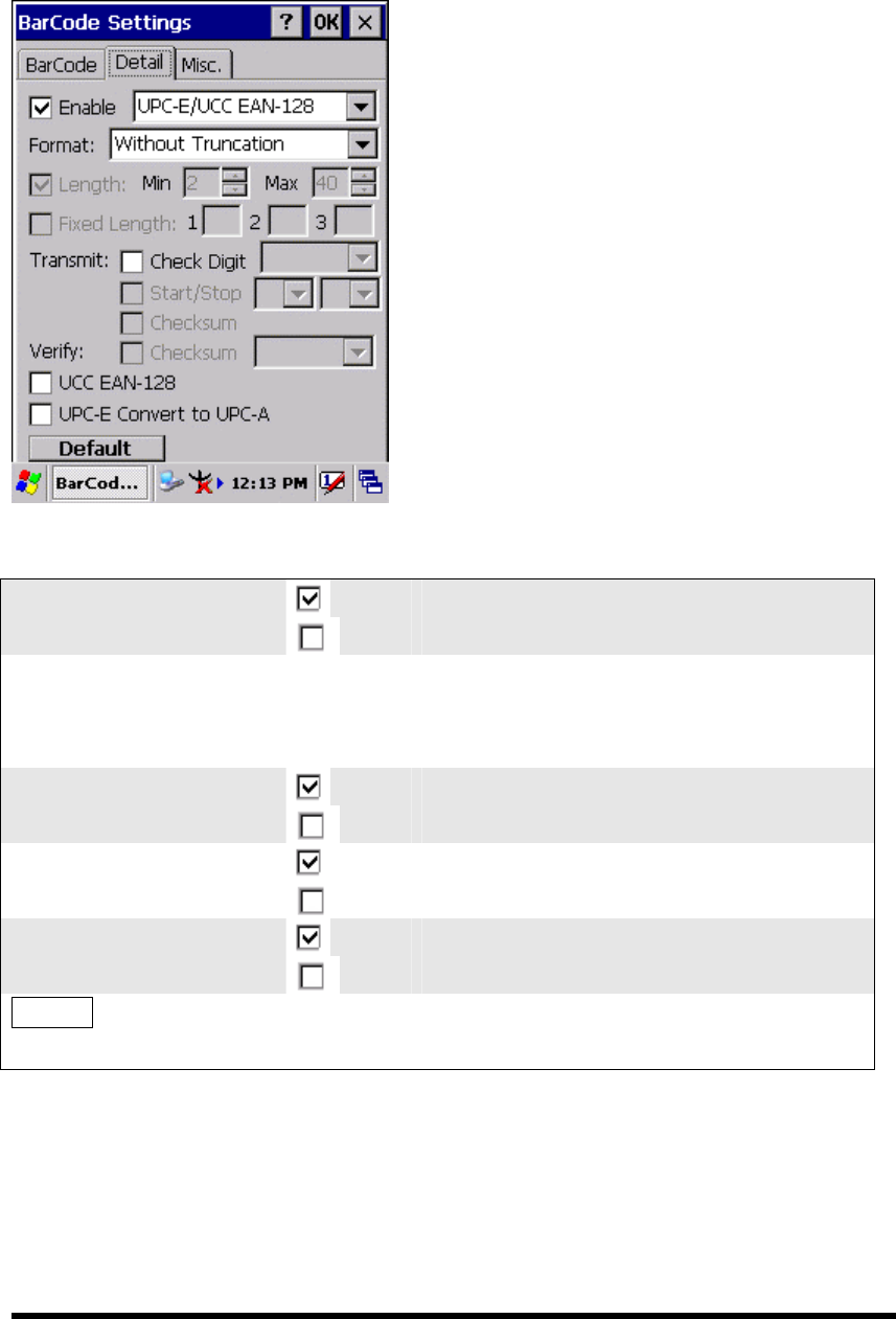
3.2.3.11 UPC-E/UCC EAN-128
P3-18
□ Enable
Enable UPC-E/UCC EAN-128
Disable UPC-E/UCC EAN-128
Format Only one of the “Without Truncation”
and “Truncate Leading Zero” can be
selected from the pull-down list.
Check Digit
Check Digit transmit
Check Digit doesn’t transmit
Enable UCC EAN-128
Enable UCC EAN-128
Disable UCC EAN-128
Enable UPC-E
Convert to UPC-A
Enable UPC-E Convert to UPC-A
Disable UPC-E Convert to UPC-A
Default Tap the “Default” tab to return back to
default setting
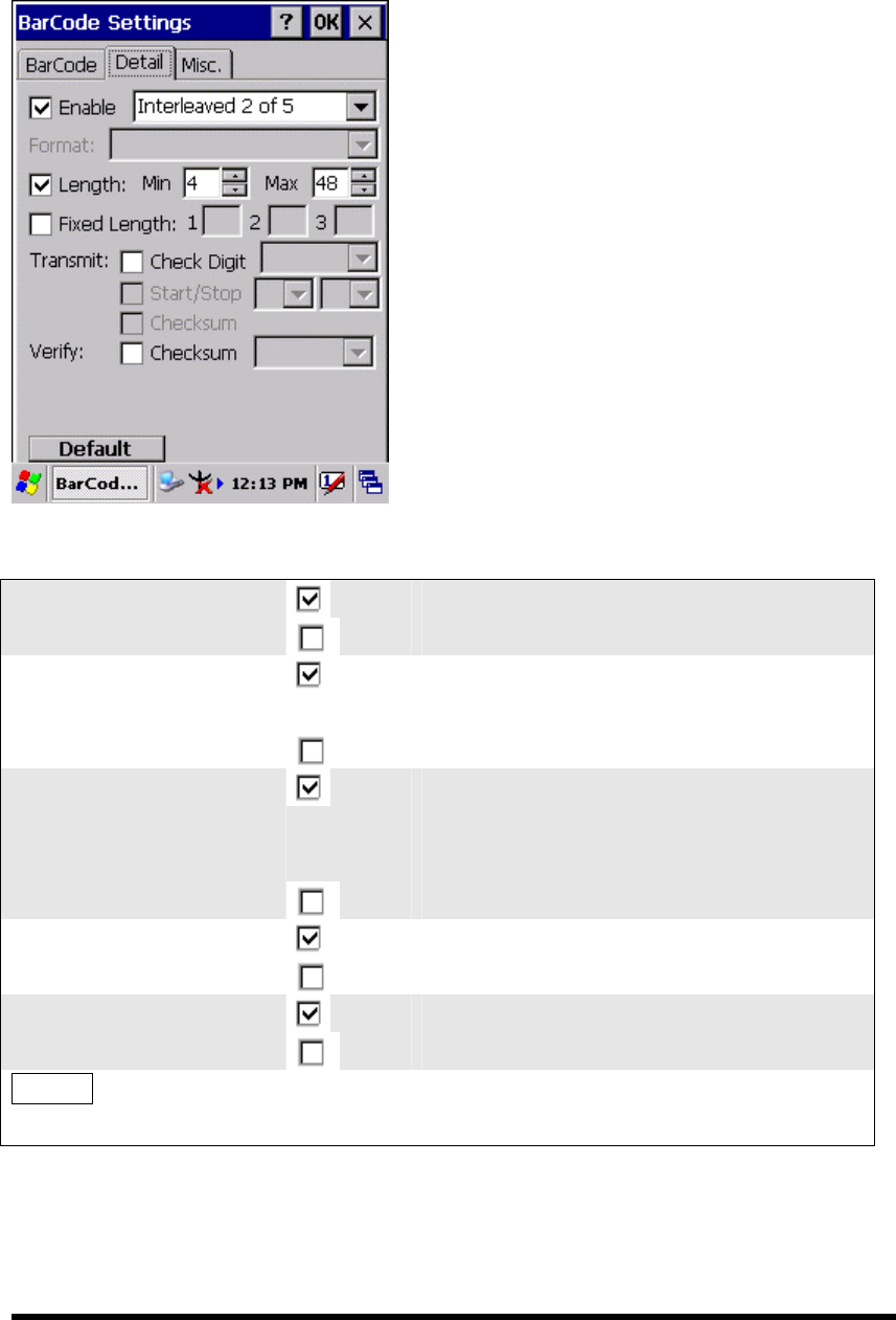
3.2.3.12 Interleaved 2 of 5
P3-19
□ Enable
Enable Interleaved 2 of 5
Disable Interleaved 2 of 5
□ Length
Min Length can be set from 2 to 96
Max Length can be set from 2 to 96
□ Fixed Length
Fixed Length 1 2-96
Fixed Length 2 2-96
Fixed Length 3 2-96
□ Check Digit
Check Digit transmit
Check Digit doesn’t transmit
Ver ify
□ Checksum
Enabled
Disabled
Default Tap the “Default” tab to return back to
default setting
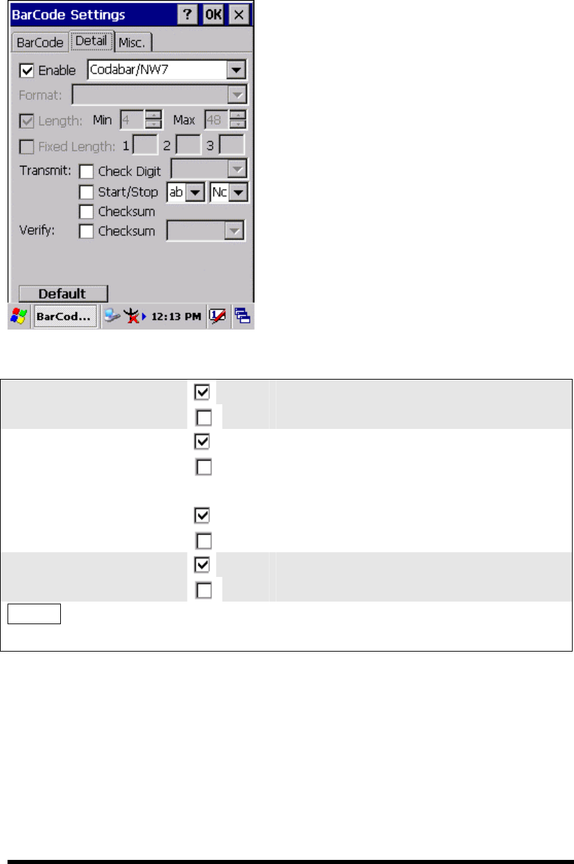
3.2.3.13 Codabar/NW7
P3-20
□ Enable
Enable Codabar/NW7
Disable Codabar/NW7
□ Start/Stop
Start/Stop transmit
Start/Stop doesn’t transmit
?????
□ Checksum
Checksum transmit
Checksum doesn’t transmit
Ver ify
□ Checksum
Enabled
Disabled
Default Tap the “Default” tab to return back to
default setting
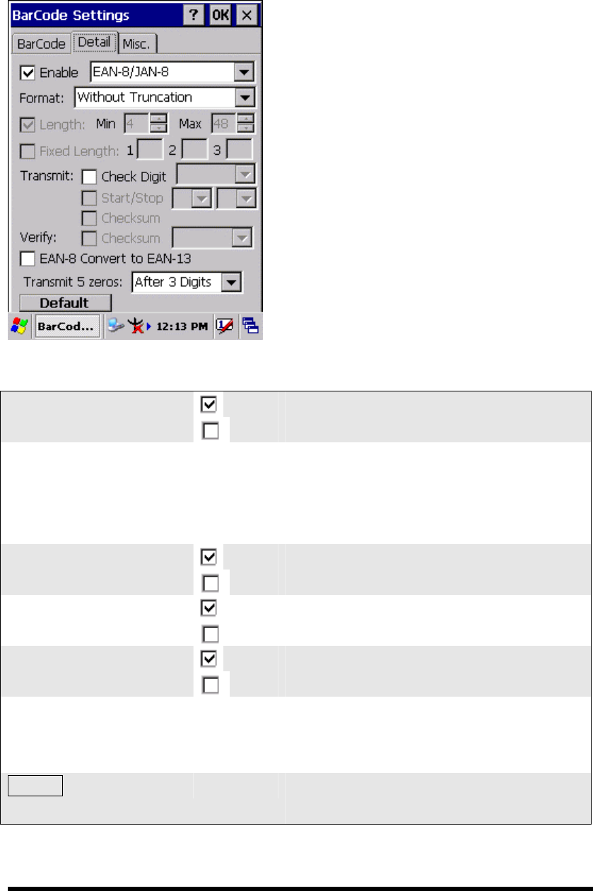
3.2.3.14 EAN-8/JAN-8
P3-21
□ Enable
Enable EAN-8/JAN-8
Disable EAN-8/JAN-8
Format Only one format of “Without
Truncation” and “Truncate Leading
Zero” can be selected from the pull-down
list.
□ Check Digit
Check Digit transmit
Check Digit doesn’t transmit
Ver ify
□ Checksum
Enabled
Disabled
□ Enable EAN-8
Convert to EAN-13
Enable EAN-8 Convert to EAN-13
Disable EAN-8 Convert to EAN-13
Transmit 5 zeros One kind of “Before BarCode” and
“After 3 Digits” is selected from the
pull-down list.
Default Tap the “Default” tab to return back to
default setting
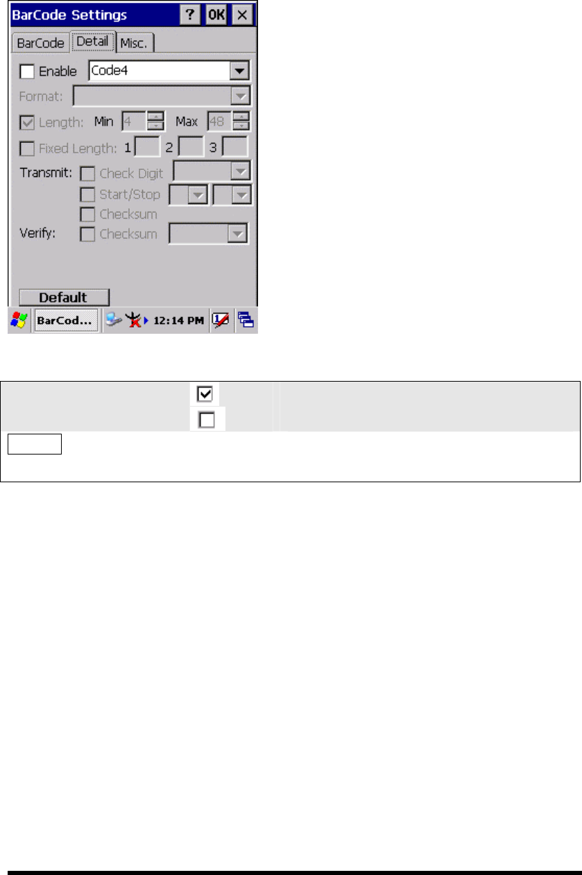
3.2.3.15 Code4
P3-22
□ Enable
Enable Code4
Disable Code4
Default Tap the “Default” tab to return back to
default setting

3.2.3.16 ISBN
P3-23
□ Enable
Enable ISBN
Disable ISBN
Default Tap the “Default” tab to return back to
default setting
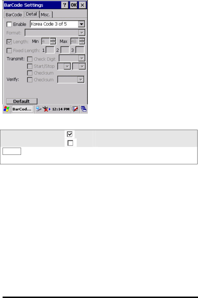
3.2.3.17 Korea Code 3 of 5
P3-24
□ Enable
Enable Korea Code 3 of 5
Disable Korea Code 3 of 5
Default Tap the “Default” tab to return back to
default setting
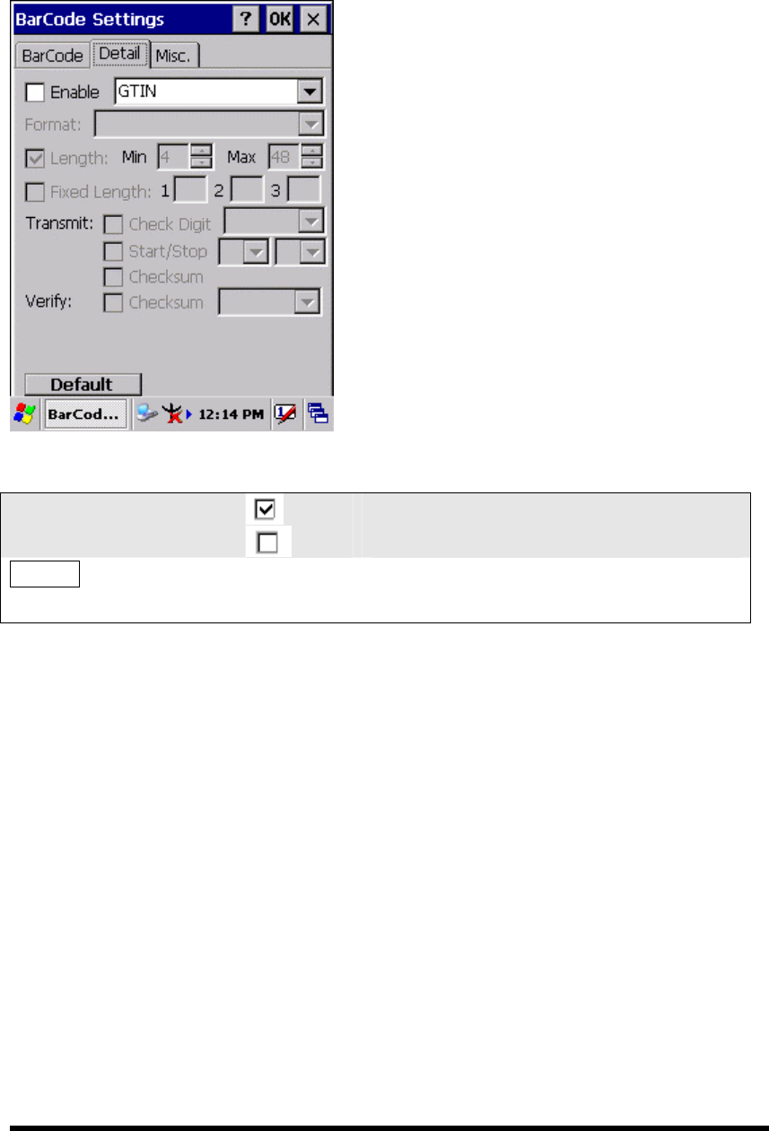
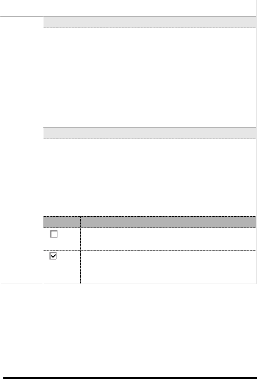
3.2.3.18 GTIN
P3-25
□ Enable
Enable GTIN
Disable GTIN
Default Tap the “Default” tab to return back to
default setting

3.2.3.19 UOC-EAN Add on 2/5
P3-26
□ Enable
Enable UPC-EAN Add on 2/5
Disable UPC-EAN Add on 2/5
Default Tap the “Default” tab to return back to
default setting
3.2.4 Brightness
Table 3-3 Brightness
ICON ITEM & FUNCTION
“Brightness Control” Applet ( Figure 3-4-1) :
Control the LCD brightness and KEYPAD Brightness
Tap the “LCD brightness” Tab, and then tune the LCD
brightness by tapping right-arrow & left-arrow. Can also tune
the LCD brightness by pressing right-direction key or
left-direction key.
Tap the “KEYPAD Brightness” Tab, and then tune the Keypad
brightness by tapping right-arrow & left-arrow. Can also tune
the Keypad brightness by pressing right-direction key or
left-direction key.
“Backlight Timeout” Applet( Figure 3-4-2~ Figure 3-4-5):
Select one power source from the pull-down list, “ AC power” &
“Battery” of Power Scheme.
Select the timeout duration from another pull-down list of “Turn off
backlight after” Tab.
< Never, 15 seconds, 30 seconds, 1 minutes, 2 minutes, 5 minutes>
The Backlight will be turned off after the selected timeout value
□ Dim backlight after 20 seconds of idleness
ITEM Function
The brightness of backlight keep the same brightness even
though system is already idle.
Brightness
The brightness of backlight will change to a little dark during
system idle situation after 20 seconds when the system isn’t
running any action.
P3-27
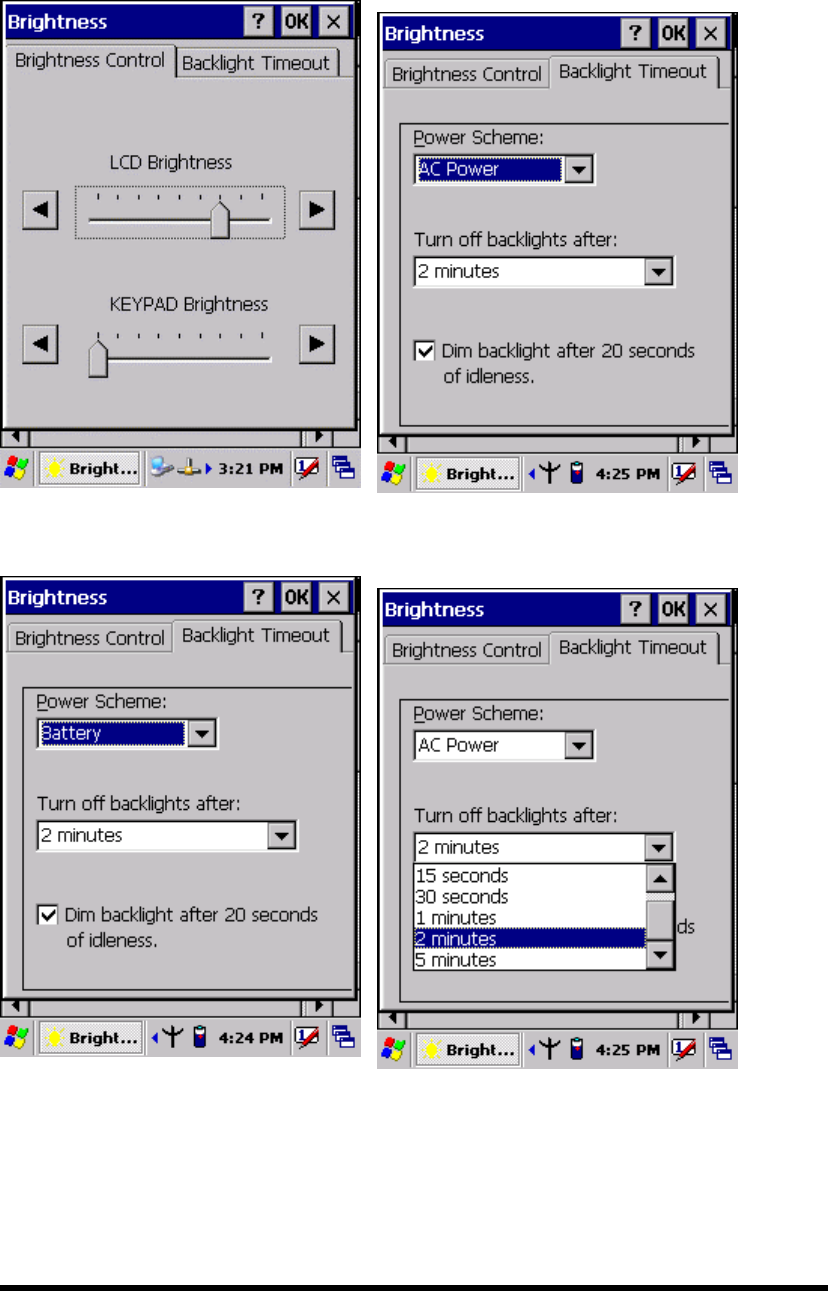
Figure 3-4-1 Figure 3-4-2
Figure 3-4-3 Figure 3-4-4
P3-28
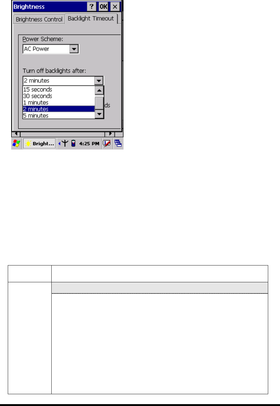
Figure 3-4-5
3.2.5 Certificates
Certificates are used by some applications for establishing trust and for secure
communications.
Certificates are signed and issued by certificate authorities and are valid for a
prescribed period of time. Windows CE manages multiple certificate stores.
Table 3-4 Certificates(A)
ICON ITEM & FUNCTION
“Store” Tab ( Figure 3-5-1) :
Certificates In the Stores tab, select the certificate store you wish to view or
modify from the drop-down list (Figure 3-5-2).
The “Trusted Authorities “store lists the top-level certificates
for authorities you trust.( Figure 3-5-2 , Figure 3-5-3)
The “My Certificates “store contains your personal certificates,
which you use to identify yourself.
Intermediate certificate authorities that help establish a chain of
trust are stored in the “Other Authorities” store.
P3-29
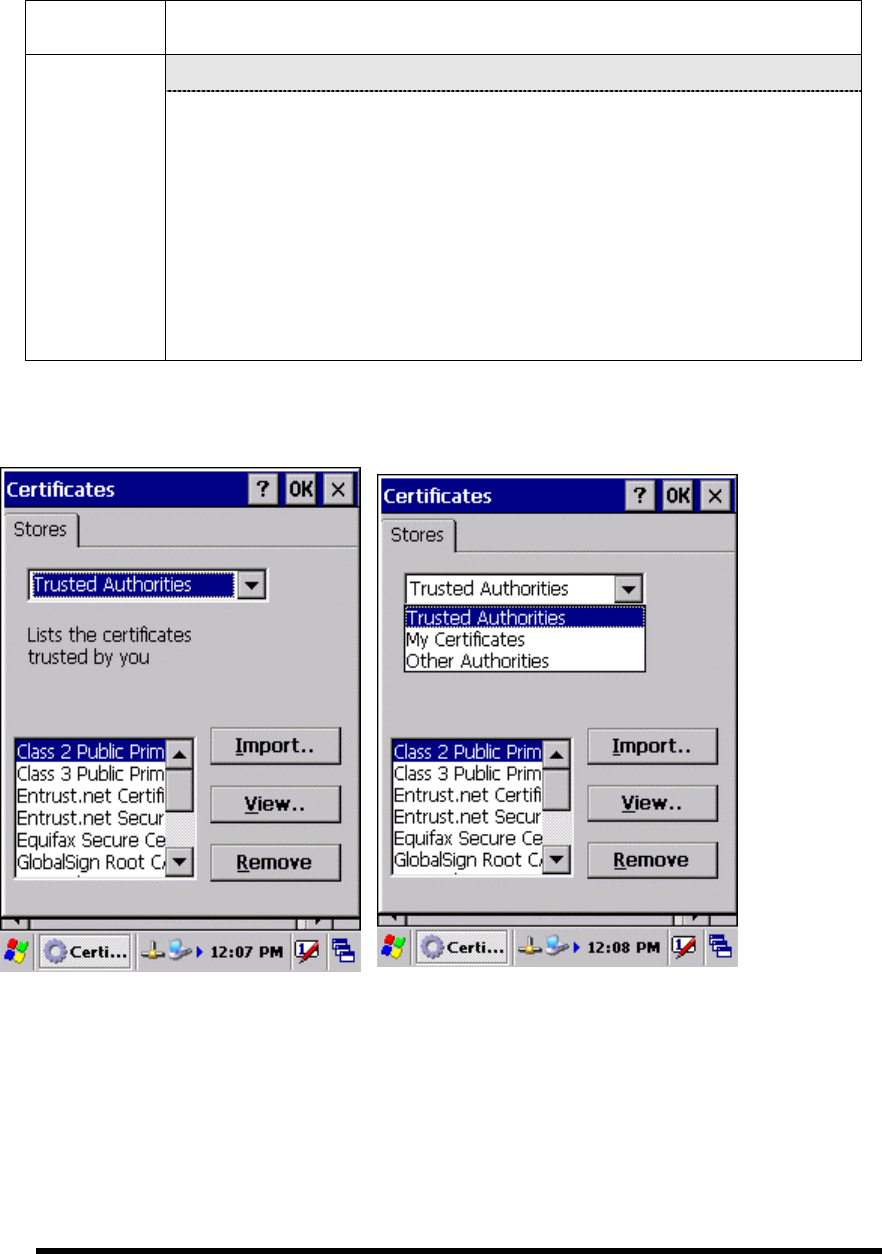
Table 3-4 Certificates(B)
ICON ITEM & FUNCTION
“Store” Tab :
Certificates To add a certificate or associated private key to the selected
store, select “Import” (Figure 3-5-4).
To view more details of the selected certificate, such as the
expanded name or expiration date, choose “View”.
To delete the selected certificate from the store, choose
“Remove”.
Figure 3-5-1 Figure 3-5-2
P3-30
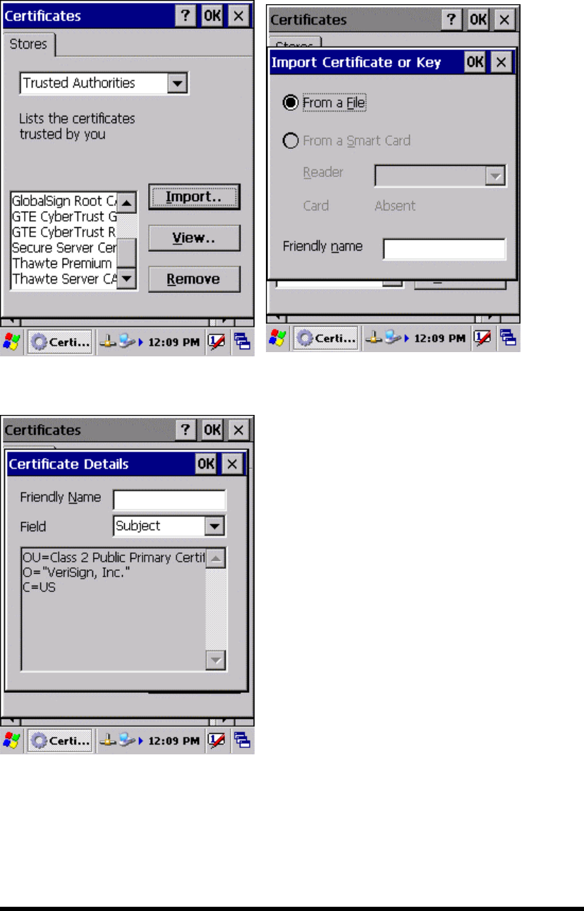
Figure 3-5-3 Figure 3-5-4
Figure 3-5-5
P3-31
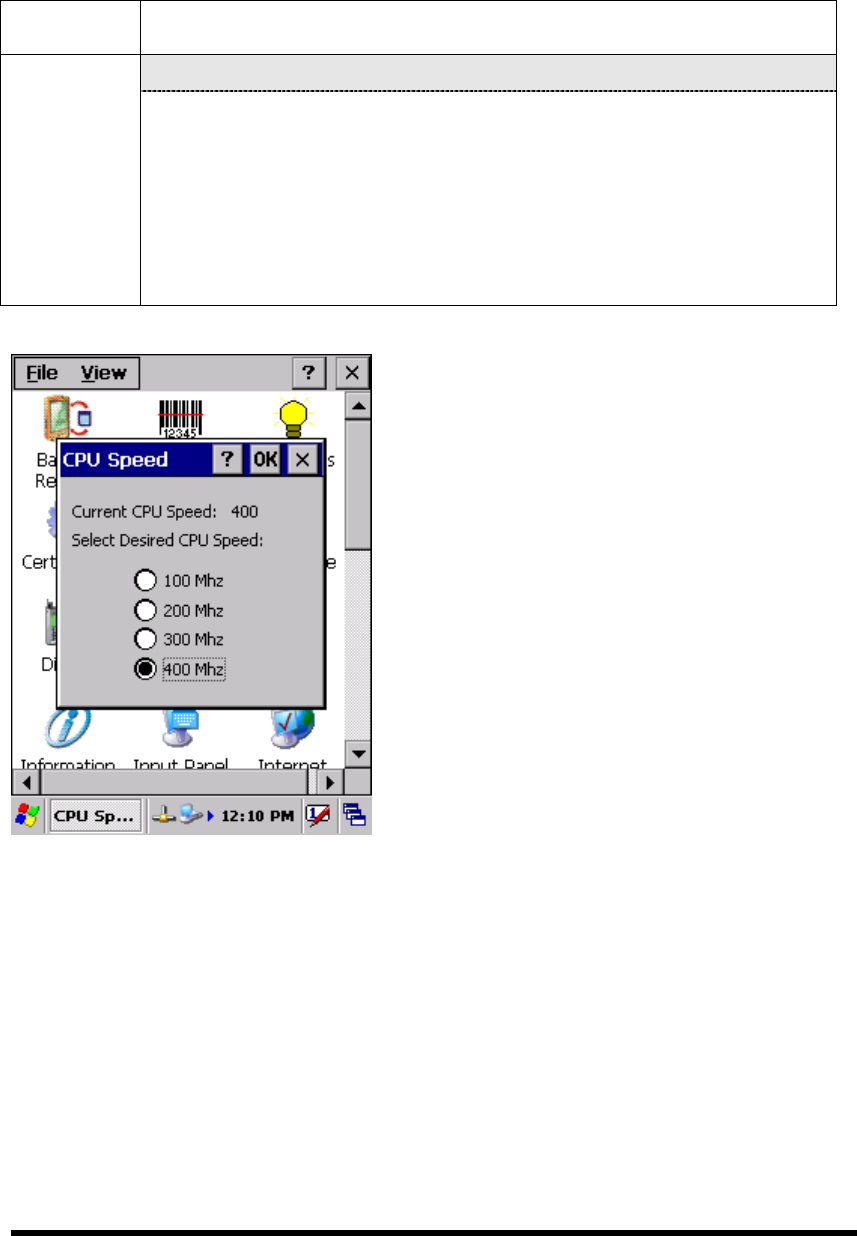
3.2.6 CPU Speed
Table 3-5 CPU Speed
ICON ITEM & FUNCTION
“CPU Speed” Tab :( Figure 3-6)
CPU Speed Provide the information of current CPU Speed.
To change the CPU Speed , select the desired CPU speed you
want.
< 100 MHz, 200MHz, 300MHz, 400MHz >
Figure 3-6
P3-32

3.2.7 Date/Time
Table 3-6 Date/Time
ICON ITEM & FUNCTION
“Date/Time” Tab :( Figure 3-6)
Date/Time Please see the detail information of 2.5.1 Setting Time and
Date on P2-22
3.2.8 Dialing Properties
Table 3-7 Dialing properties(A)
ICON ITEM & FUNCTION
“Dialing Properties” Tab :( Figure 3-7-1)
In the When dialing from list, select the “Location” where you
want to change settings.(Figure 3-7-2)
To create a new location, select “New”. Enter the name of the
location, and then select “OK”.(Figure 3-7-3)
Enter or edit the area code and local country code as needed.
In Dial using, select “Tone dialing” or “Pulse dialing”. Most
phone lines are tone.
To automatically disable call waiting, select “□ Disable call
waiting by dialing", select the appropriate number sequence in the
list, or enter a new sequence.
Dialing
Properties
Editing dialing patterns (Figure 3-7-4)
Using the codes listed in the topic, revise the dialing patterns as
needed.
Notes:
If you need to use character other than the ones listed here,
use manual dialing.
Hyphens and spaces in dialing strings are ignored.
Some modems may not respond to the following characters,
even though your device lets you add them to the dial
string.
P3-33
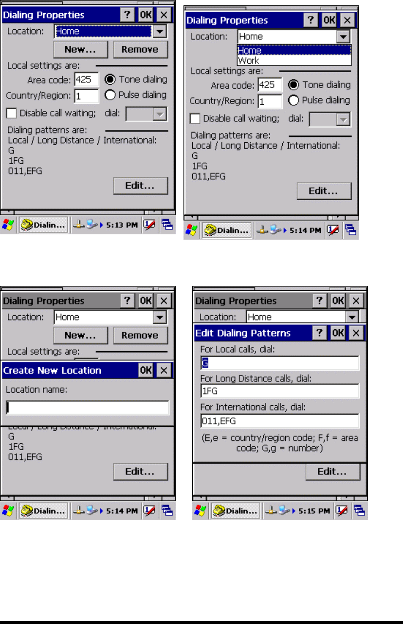
Figure 3-7-1 Figure 3-7-2
Figure 3-7-3 Figure 3-7-4
P3-34

3.2.9 Display Properties
Table 3-8 Display properties(A)
ICON ITEM & FUNCTION
“Background” Tab :( Figure 3-8-1)
From the “Image” list, select an image you want as the
background of the desktop.(Figure 3-8-2)
To locate an image in another folder, select “Browse”.(Figure
3-8-3)
To have the image cover the entire background, select “ □Tile
image on background”
“Appearance” Tab(Figure 3-8-4)
Display
Change the color scheme :( Figure 3-8-5)
From the” Scheme” list, select a scheme.
View your choice in the preview box. If you like the
scheme, select “Apply”.
Create a custom color scheme:
From the “Item” list, select a display item.
From the “Basic colors” list, select a color, and select
“OK”.
View your color selection(s) in the Preview box.
To save the scheme, select “Save”.
In the “Save this color scheme as” box, enter a name
for the scheme, and select “OK”.
Select “Apply”.
P3-35
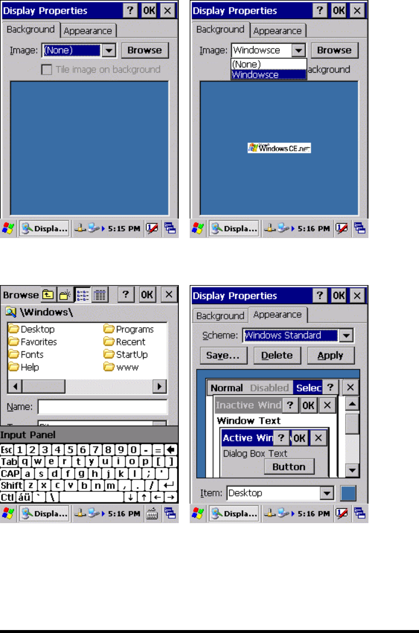
Figure 3-8-1 Figure 3-8-2
Figure 3-8-3 Figure 3-8-4
P3-36
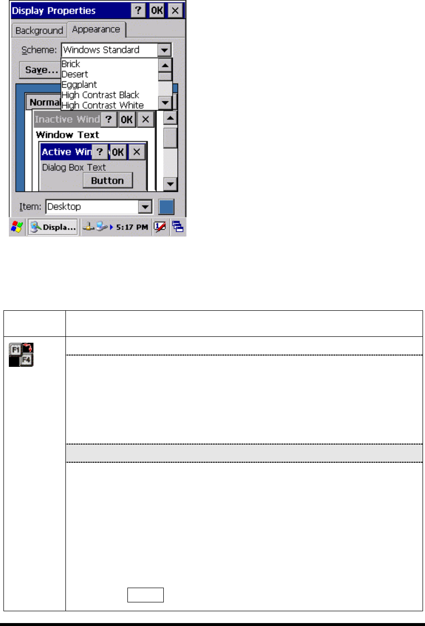
Figure 3-8-5
3.2.10 Fkey Settings
Table 3-9 FKey (A)
ICON ITEM & FUNCTION
“Hot keys” Tab :( Figure 3-9-1)
Assign your hot keys to wakeup system after it goes into sleep
mode.
To select which key(s) that can wakeup system, then, tap “OK”.
< F1 key, F2 key, F3 key, F4 key and Scanner Buttons>
“AP Settings” Tab(Figure 3-9-2)
FKey
Setting
To assign your favorite application program to F1,F2,F3 and F4 hot
keys.
Choose one of F1, F2, F3 and F4 from pull-down list.(Figure
3-9-3)
To tap “ Open” inside “Assign program” applet.
Select one application program you want from program list, Then,
choose “OK”. (Figure 3-9-4)
To tap Default tab to return back to default setting. (Figure 3-9-2)
P3-37
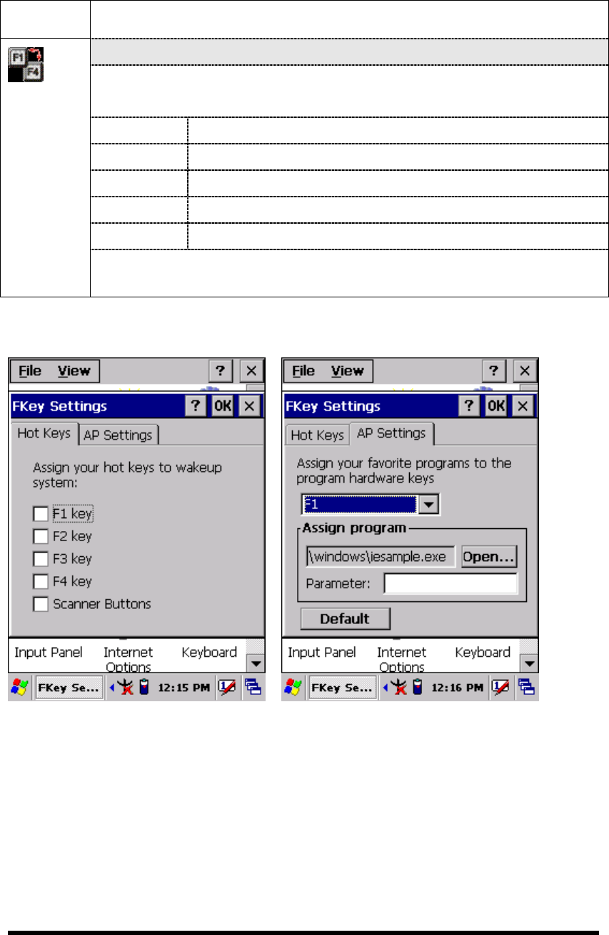
Table 3-9 FKey (B)
ICON ITEM & FUNCTION
“AP Settings” Tab(Figure 3-9-2)
The default setting for F1~F4:
F Key Name of Application Program
F1 Internet Explorer
F2 WordPad
F3 Inbox
F4 My Computer
FKey
Setting
Figure 3-9-1 Figure 3-9-2
P3-38
Figure 3-9-3 Figure 3-9-4
3.2.11 Information
Table 3-10 Information
ICON ITEM & FUNCTION
“Information” Tab :
Information
Provide hardware version, Software version, ROM size, RAM
size, Serial No. and Configuration No.
3.2.12 Input Panel
Table 3-11 Display properties(A)
ICON ITEM & FUNCTION
“Input panel” Tab :( Figure 3-10-1)
Input Panel Select the input method you want to change.
To change the Soft Keyboard Options , tap “Option” (Figure
3-10-2)
.
P3-39
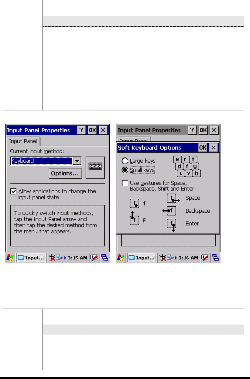
Table 3-11 Display properties(B)
ICON ITEM & FUNCTION
“Input panel” Tab :
Input Panel Change the soft keyboard options as desired, selecting from:
Large or small keys
Using gestures for space, black-space shift, and enter.
To exit the soft keyboard Options, press “OK” on the control
bar, or press the <Enter> key on the keypad.
To exit the Input Panel, press “OK” on the control bar, or press
the <Enter> key on the keypad.
.
Figure 3-10-1 Figure 3-10-2
3.2.13 Internet Options
Table 3-12 Internet Options(A)
ICON ITEM & FUNCTION
“General” Tab :( Figure 3-11-1)
Internet
Settings
Type in the URL of desired start page and the desired search
engine. You also change the Cache Size, clear the Cache and
Clear the History..
P3-40

Table 3-12 Internet Options(B)
ICON ITEM & FUNCTION
“Connection” Tab :( Figure 3-11-2)
Modify the network access setting as desired.
“Security” Tab (Figure 3-11-3)
Modify the security settings as desired. You can enable any of
the following by tapping the checkbox:
Allow cookies
Allow TLS 1.0 security
Allow SSL 2.0 security
Allow SSL 3.0 security
Warm when switching across secure and insecure areas.
“Advanced” Tab (Figure 3-11-4)
Internet
Settings
Modify the security settings as desired. You can enable any of
the following by tapping the checkbox:
Display Image in pages
Play sounds in pages
Enable scripting
Display a notification about every script error
Underline links-
○ Never
○ Always
○ Hover
P3-41
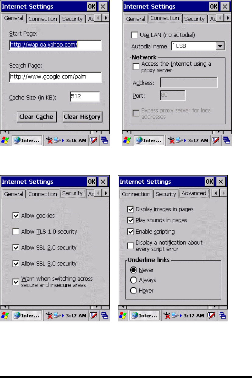
Figure 3-11-1 Figure 3-11-2
Figure 3-11-3 Figure 3-11-4
P3-42
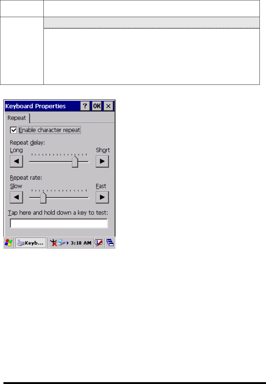
3.2.14 Keyboard
Table 3-13 Keyboard(A)
ICON ITEM & FUNCTION
“Repeat” Tab :( Figure 3-12)
Keyboard To change the amount of time between depressions before
repetition starts, adjust the Repeat delay slider
To change the repeat rate, adjust the Repeat rate slider.
Test your new setting.
Tap “ OK” to exit the “Keyboard” Tab.
Figure 3-12
P3-43
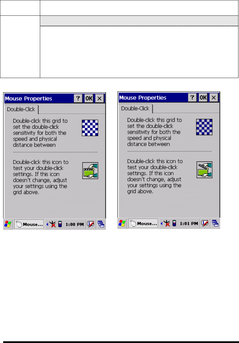
3.2.15 Mouse
Table 3-14 Mouse(A)
ICON ITEM & FUNCTION
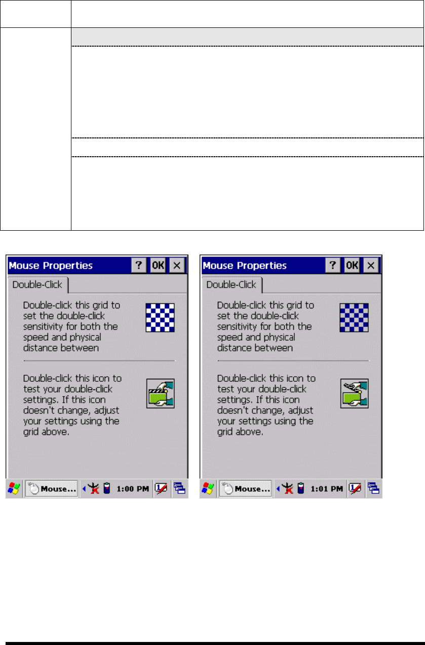
“Double-Click” Tab :( Figure 3-13-1,Figure 3-13-2)
Mouse Double-click the checkerboard grid at comfortable speed
Double-click the Test icon to test your setting.
The function is OK if the figures are changed from Figure
3-13-1 to Figure 3-13-2.
To tap “OK” to exit the Mouse tab.
Figure 3-13-1 Figure 3-13-2
P3-44

3.2.16 Network and Dial-up Connections
Table 3-15(A) Network and Dial-up Connections
ICON ITEM & FUNCTION
Network
and Dial-up
Connections
“Connection” Tab :
To create a “Dial-up Connection”:
Double-tap the “Make New connection”.
In the “Make New Connection” dialog box, enter a name for
the connection.
Select “Dial-Up Connection”.
Select the “Next” button.
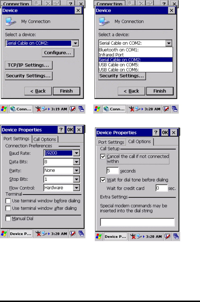
Select the modem you want use.
Select “Configure”
Under “Connection Reference”, use the default settings
provided. If you can’t connect using these settings, see your
ISP or network administrator for specific information. If you
want to always enter a phone number before connecting,
Select “Manual Dial”. Select “OK”.
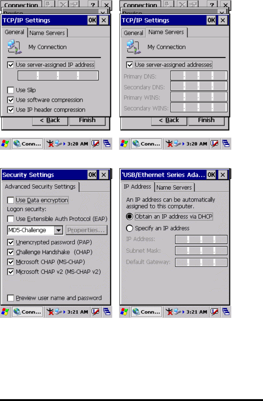
Select “TCP/IP Settings”. In the “General” tab, ensure “Use
Server-assigned IP address” is selected. In the “Name
Servers” tab, ensure “Use Server-assigned addresses” is
selected, and select “OK”. If you are unable to connect with
these default settings, see your ISP or network administrator
for specific TCP/IP information.
Select the “Next” button and type the telephone number.
Select the “Finish” button.
The connection you just created appears as an icon in the “Network
and Dial-up Connections” folder.
Set up a point-to-Point Protocol(PPP) account with an ISP and
obtain the following information:
Access telephone number
User name
Password
P3-45
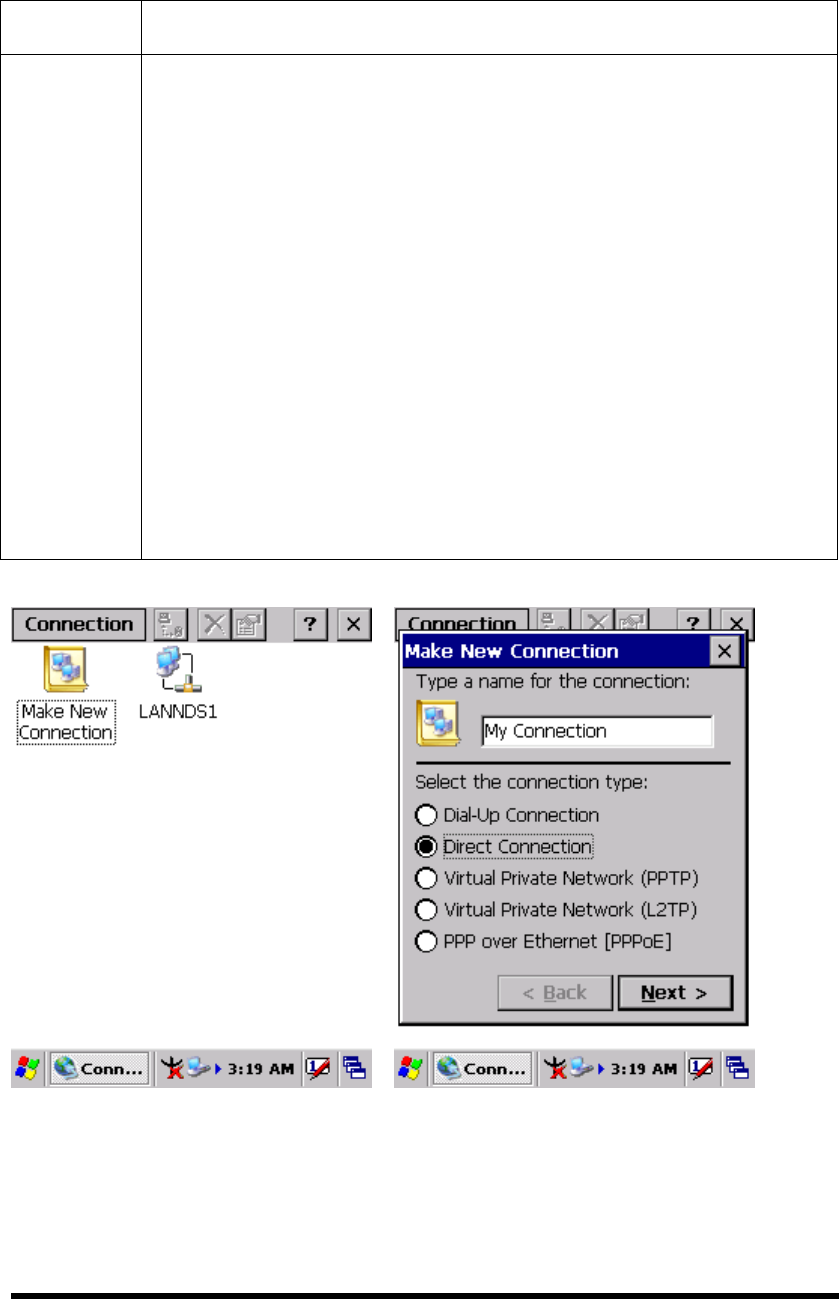
Table 3-15(A) Network and Dial-up Connections
ICON ITEM & FUNCTION
Network
and Dial-up
Connections
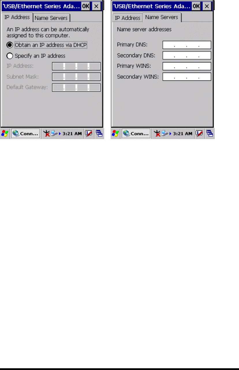
Once you have established an account, create a new connection on
your device. When creating this connection, you should be able to use
all of the default TCP/IP settings provided in the Make New
Connection Wizard. If you can’t connect using the default settings,
contact your ISP or access your ISP’s Web site for specific TCP/IP
information as well as primary and secondary DNS address.
Modify connection setting
Select Start > Settings > Network and Dialup Connections
Select the icon for connection settings you want to modify.
Select File > Properties, or double- tap the appropriate icon.
Select desired options. There may be additional settings that
depend on the connection. To modify, select the icon and
select the icon and select Advanced Settings… from the
menu.
P3-46
P3-47
P3-48
P3-49
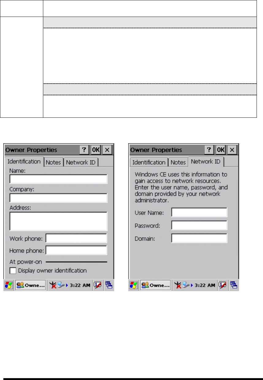
3.2.17 Owner
Table 3-16 Owner
ICON ITEM & FUNCTION
“Identification” Tab : (Figure 3-15-1)
Fill in or edit the data as desired.
To have this information displayed when you start your device,
select “Display Owner Identification” at Power On.
To set up identification for remote networks, see Setting up
identification for remote networks.
“Network ID” Tab: (Figure 3-15-2)
Owner
Enter the user name, password, and domain name you use to log
on to remote network.
Figure 3-15-1 Figure 3-15-2
P3-50
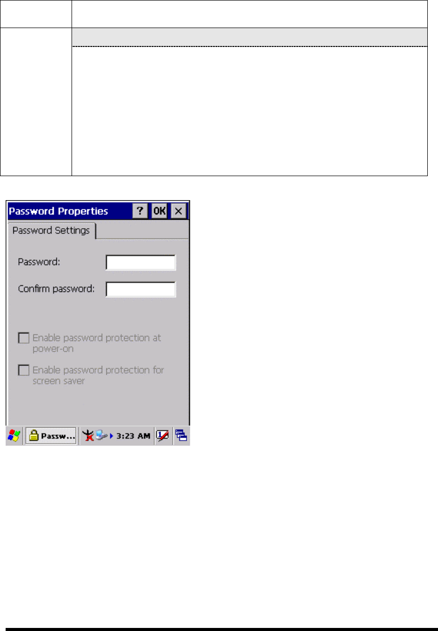
3.2.18 Password
Table 3-17 Password
ICON ITEM & FUNCTION
“Password Setting” Tab : (Figure 3-16)
Password Enter the password
In the “Confirm password “box, enter the password again.
To require the password on startup, select “Enable password
protection at power- on“. and/or select “Enable password
protection for screen saver”
To exit the Password control panel, press “OK” from the
control bar, or press the <Enter> key on the keypad.
Figure 3-16
P3-51
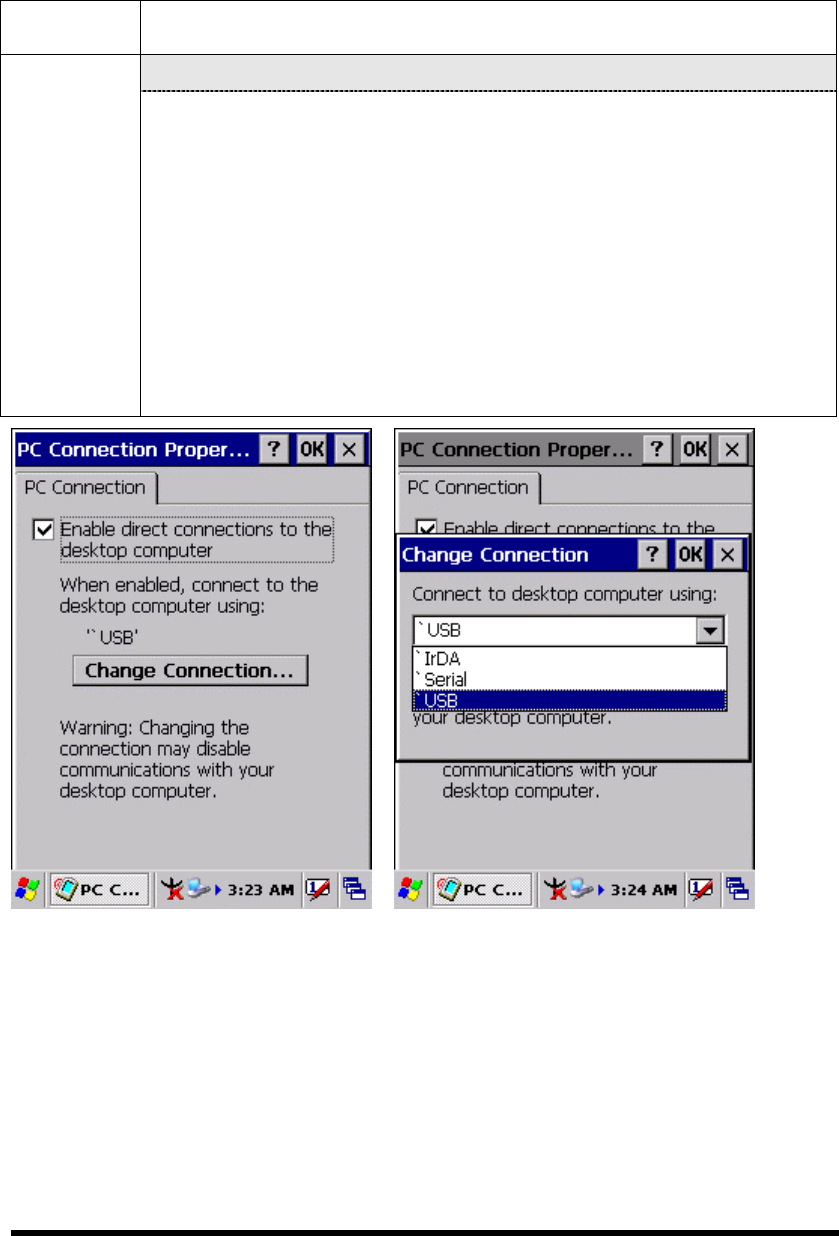
3.2.19 PC Connection
Table 3-18 PC Connection
ICON ITEM & FUNCTION
“PC Connection” Tab : (Figure 3-17-1)
PC
Connection
Select the first checkbox to enable direct connections to the
desktop computer. (Figure 3-17-1)
Tap the “Change Connection…” button to modify the
connection method from USB, IrDA, or Serial. (Figure 3-17-2)
To exit the “Change Connection” dialog, press “OK” from the
control bar, or press the <Enter> key on the keypad.
To exit the “PC Connection” properties control panel, press
“OK” from the control bar, or press the <Enter> key on the
keypad.
Figure 3-17-1 Figure 3-17-2
P3-52
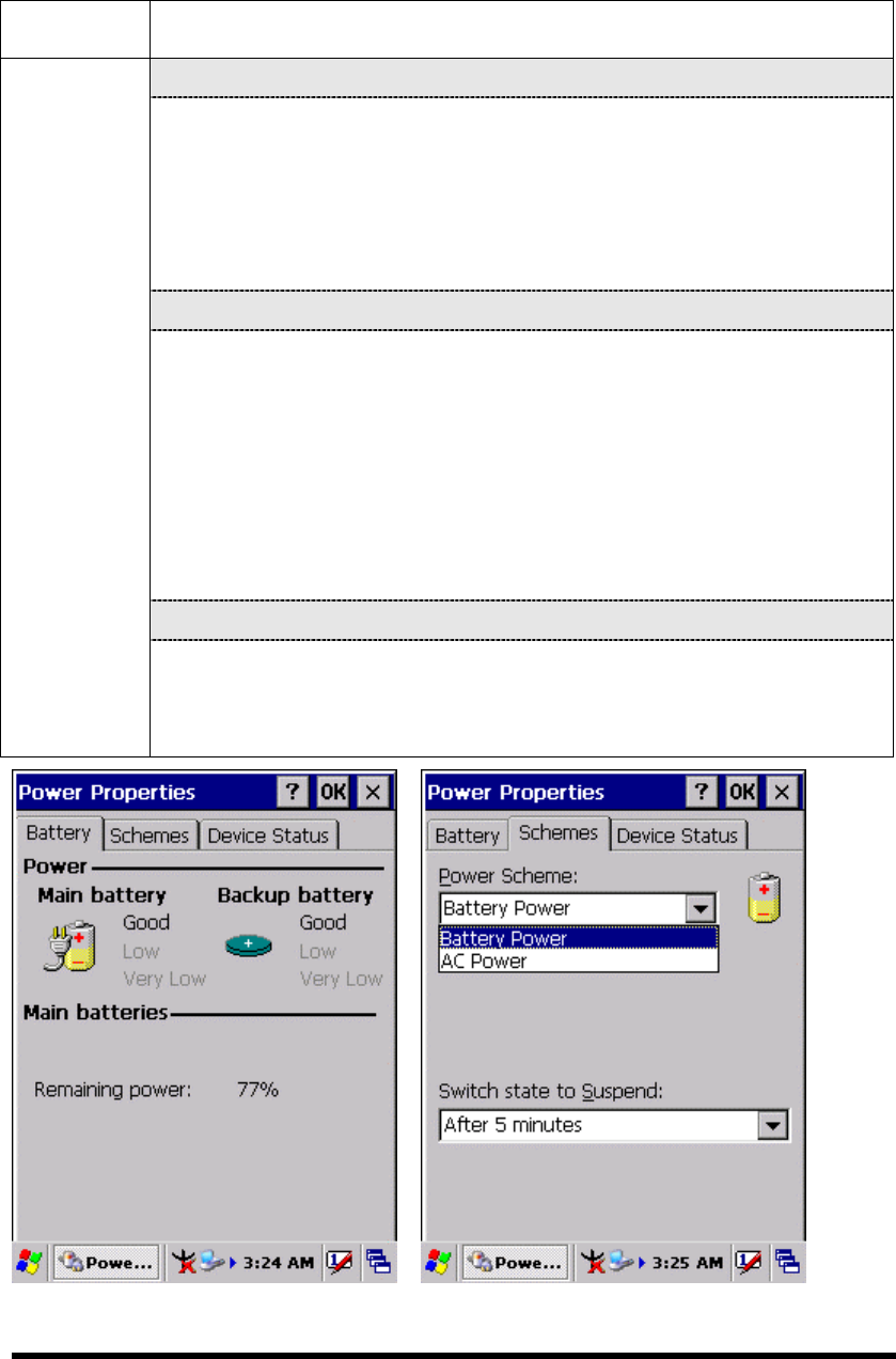
3.2.20 Power
Table 3-19 Power
ICON ITEM & FUNCTION
“Battery” Tab : (Figure 3-18-1)
Provide change level indicators for Main battery and Backup
battery.
To exit Battery control panel, press “OK” from the command
bar, or press <Enter> key on keypad.
“ Schemes” Tab: (Figure 3-18-2)
The Scheme Tab allows you to determine the time to switch
state to Suspend mode when using either Battery Power or AC
Power.
Select Battery Power or AC Power as the power scheme from
the pull-down list.( Figure 3-18-2)
Select the time to suspend mode from the pull-down list.
( Figure 3-18-3)
“Device Status” Tab: ( Figure 3-18-4)
Power
Provide power level of device – The power level ranges from
“ High(D0)” which means the device is at the highest power level to
“Off(D4)” which means the device is at the lowest power level.
Figure 3-18-1 Figure 3-18-2
P3-53
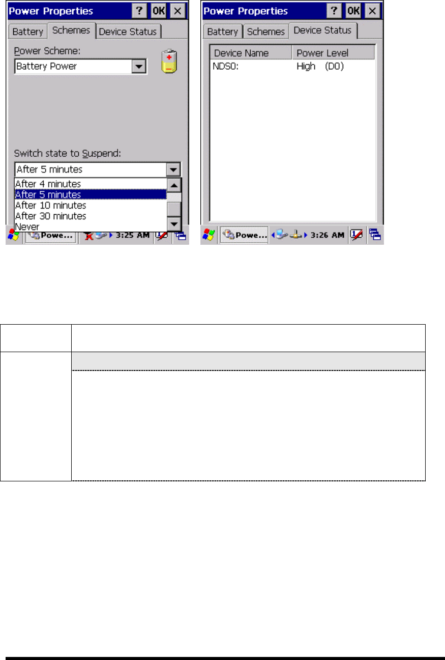
Figure 3-18-3 Figure 3-18-4
3.2.21 Regional Settings
Table 3-20 Regional Settings
ICON ITEM & FUNCTION
“Region” Tab : (Figure 3-19-1)
Regional
Settings
Select the desired location/language.
Review the Appearance samples in the bottom half of the
screen.
Select the Tab at the top for any settings you wish to change,
Options to modify include Number, Currency, Time, and Date.
( Figure 3-19-3 ~ Figure 3-19-9)
P3-54
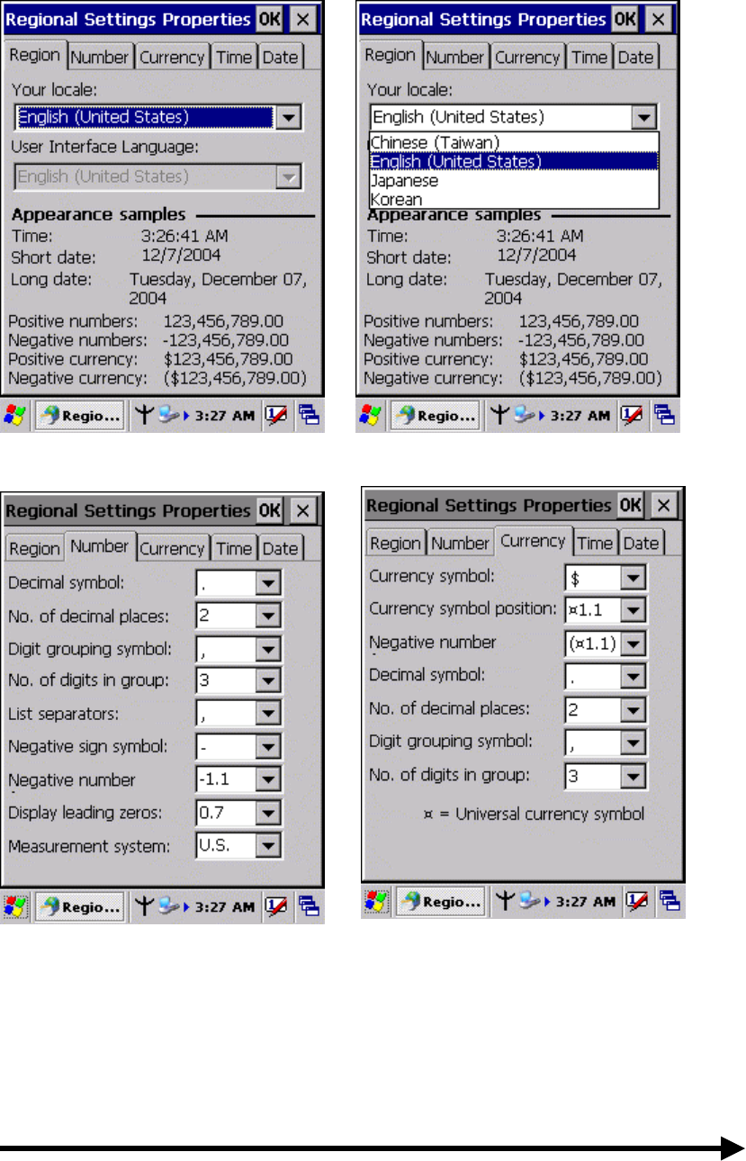
Figure 3-19-1 Figure 3-19-2
Figure 3-19-3 Figure 3-19-4
P3-55
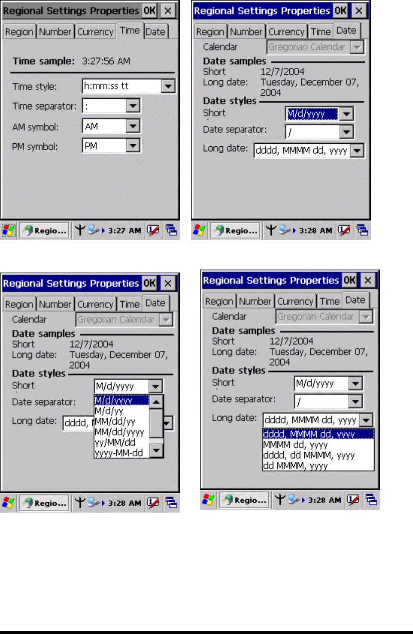
Figure 3-19-5 Figure 3-19-6
Figure 3-19-7 Figure 3-19-8
P3-56
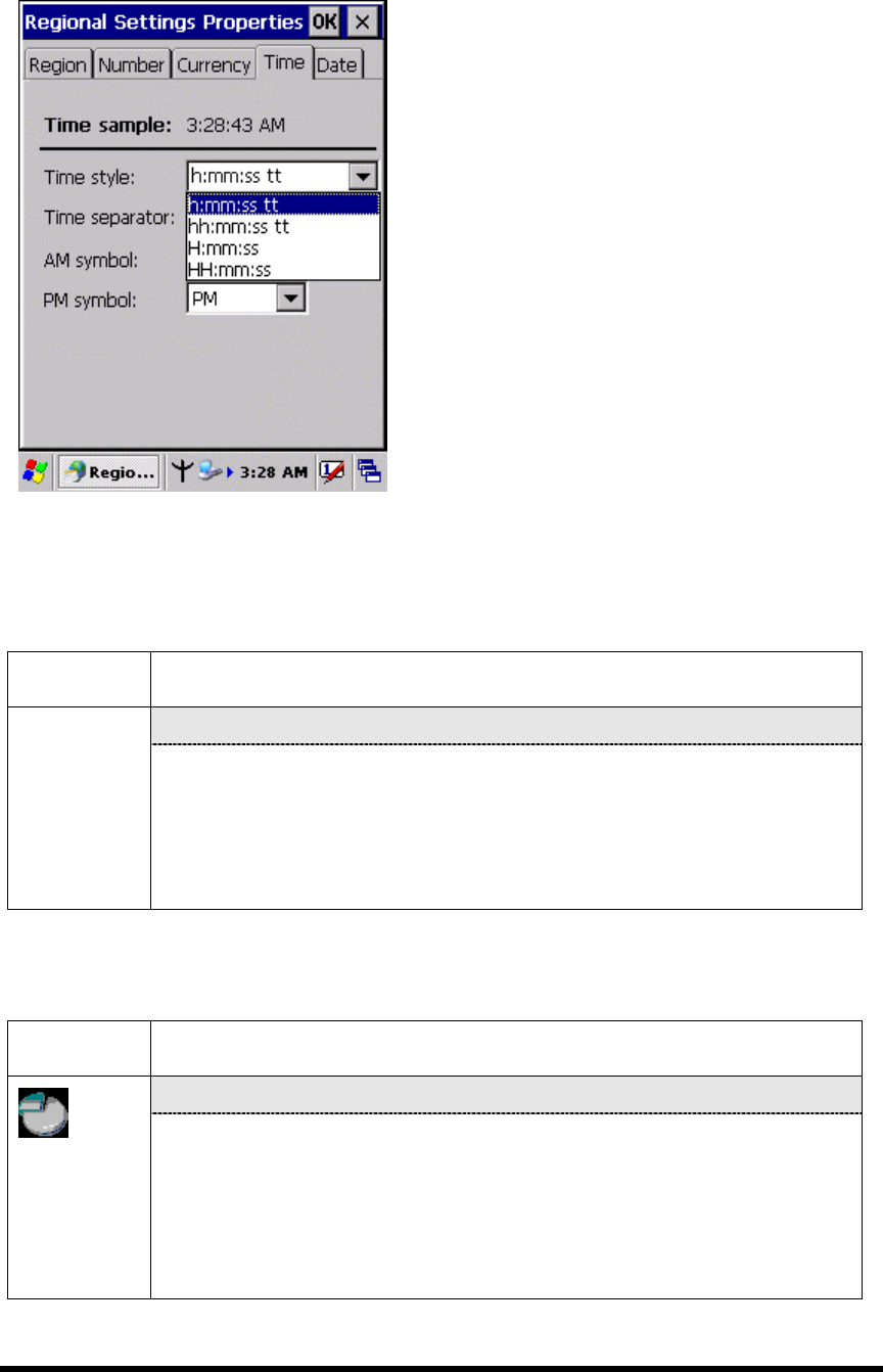
Figure 3-19-9
3.2.22 Remove Programs
Table 3-21 Remove Programs
ICON ITEM & FUNCTION
“Remove Programs” Tab :
Remove
Programs
Only user installed programs can be removed.
Select the program you wish to remove from the list and press
“remove” button.
3.2.23 Storage Manager
Table 3-22 Storage Manager(A)
ICON ITEM & FUNCTION
“Storage Manager” Tab : (Figure 3-20)
Storage
manager
To change Storage properties control panel default settings:
Insert. Compact Flash(CF) or Secure digital (SD) storage card into
the unit.
Select Start > Settings > Control Panel > Storage Properties
P3-57
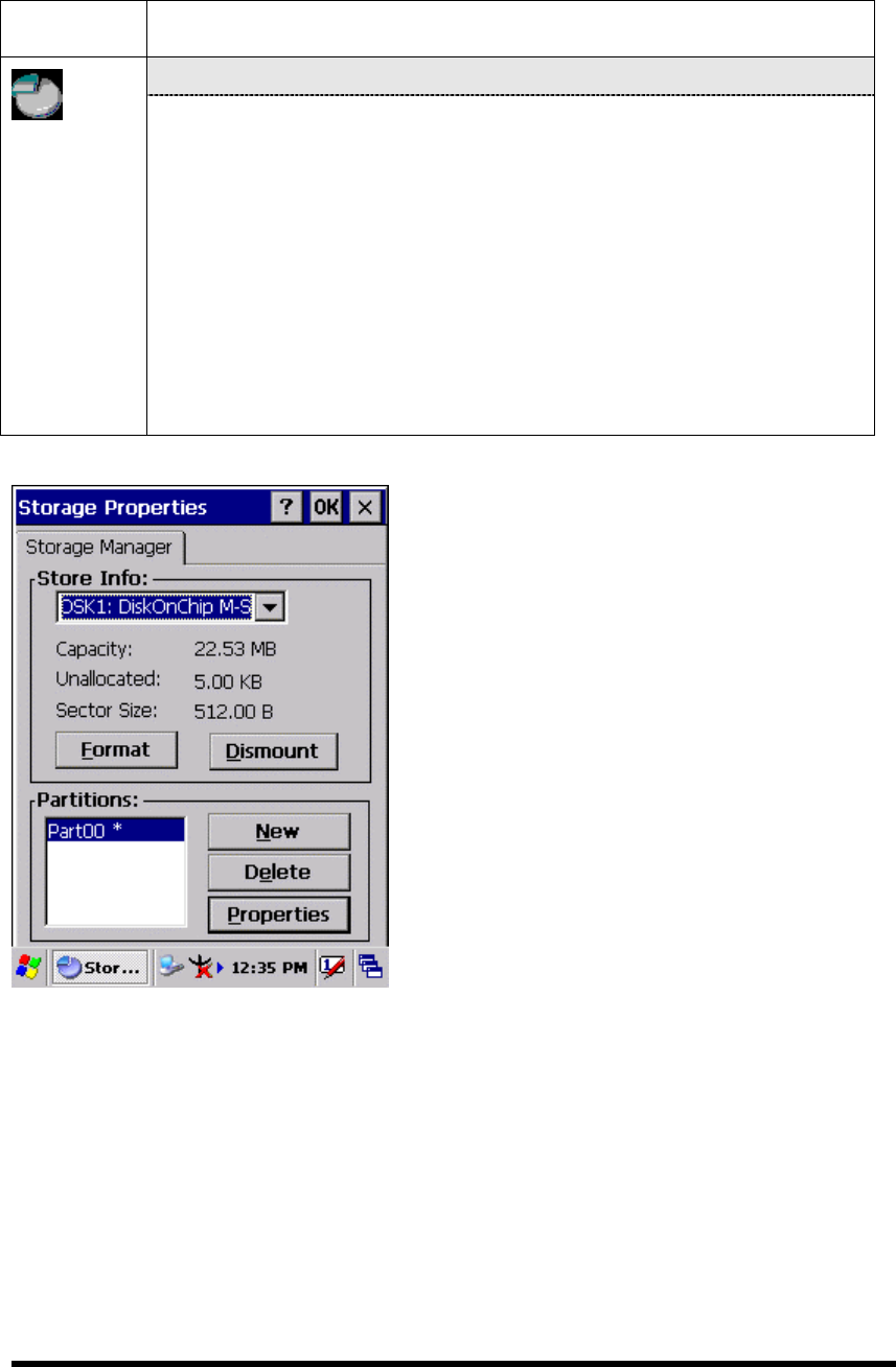
Table 3-22 Storage Manager(B)
ICON ITEM & FUNCTION
“Storage Manager” Tab : (Figure 3-20)
Storage
manager
From the “Storage Info” pull-down list, select the desired
storage device.
You can also format, dismount, and create partitions on storage
devices using this control panel.
To save and exit the Storage Properties control panel, press
“OK” from the control bar, or press the <Enter> key on the
keypad.
Caution: Dismounting or formatting the DiskOnChip will
erase all files and program stored in Flash Memory
Figure 3-20
P3-58
3.2.24 Stylus
Table 3-23 Stylus(A)
ICON ITEM & FUNCTION
“Double-Tap” Tab : (Figure 3-21-1,Figure 3-21-2)
Double-tap the checkerboard grip at a comfortable speed.
Double-tap clapboard to test your settings
The function is OK if the figures are changed from Figure
3-21-1 to Figure 3-21-2.
To tap “OK” to exit the Stylus Properties.
“Calibration”: (Figure 3-21-3)
Stylus
In the Welcome Wizard, you tapped a target with the stylus to set
the amount of pressure needed for the screen to respond to your
stylus taps.
Please also see 2.4.3: Calibration of the touch Screen
Figure 3-21-1 Figure 3-21-2
P3-59

Figure 3-21-3
3.2.25 System
Table 3-24 System(A)
ICON ITEM & FUNCTION
“General” Tab : (Figure 3-22-1)
To show:
Firmware information
Information about Processor type, Memory size, Expansion
card
“Memory”: (Figure 3-22-2)
System
Move the slider to adjust memory allocation. Default storage
memory is normally is normally set to about 8MB with the
reminder assigned to Program memory.
Press the “OK” key on the Keypad.
Note: the difference is occupied by OS between the RAM size in
Information properties and total memory size of storage memory
and program memory
P3-60
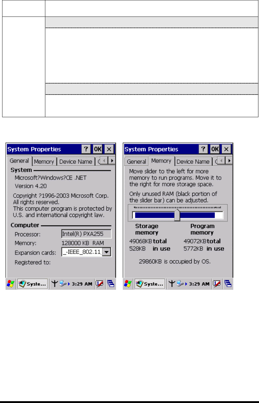
Table 3-24 System(B)
ICON ITEM & FUNCTION
“Device Name” Tab : (Figure 3-22-3)
Your device uses this information to identify itself to other
computers.
The input panel will open to facilitate data entry.
To close the Device Name, press the “OK” button, or press the
<Enter> key on keypad.
“Copyrights” Tab: (Figure3-22-4)
System
Refer to this tab for specific copyright data. As a user, you are
responsible to read this statement.
Figure 3-22-1 Figure 3-22-2
P3-61
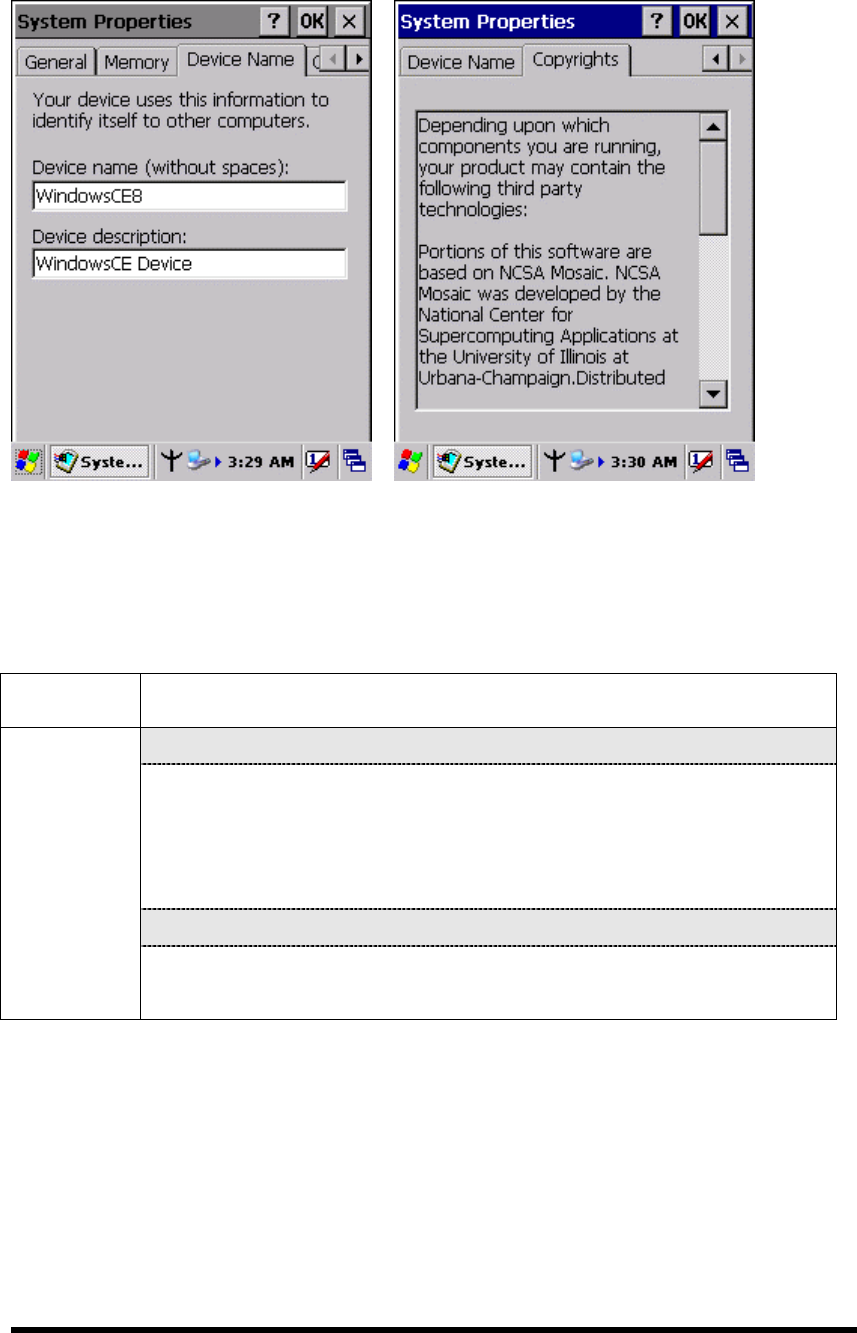
Figure 3-22-3 Figure 3-22-4
3.2.26 Volume & Sounds Properties
Table 3-25 Volume & Sound
ICON ITEM & FUNCTION
“Volume” Tab : (Figure 3-23-1)
The factory default for Volume is the forth level. You can adjust
the volume to your environment and comfort.
Set the volume by adjusting the slider from Soft to Loud,
or press Right or Left edge of Navigation keys
“Sounds ” Tab: (Figure3-23-2)
Volume &
Sound
Enable the desired sounds for key clicks, screen taps,
notifications, and applications.
P3-62
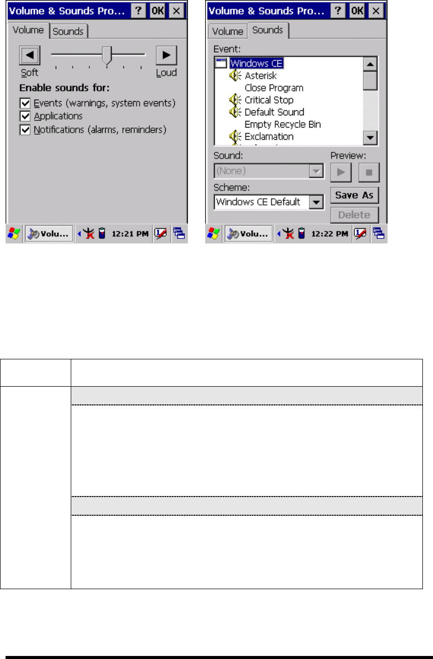
Figure 3-23-1 Figure 3-22-2
3.3 Taskbar and Start Menu
Table 3-26 Taskbar and Start menu
ICON ITEM & FUNCTION
“General” Tab :
In this tab, You can change the position of the Taskbar and Start
menu
Is always on top or not
Auto hide or not
Show Clock or not
“Advanced ” Tab:
Taskbar and
Start Menu
Tap the “Clear” button to remove the contents of the Documents
Menu.
Enable “□ Expand Control Panel" to list all icons of Control
Panel from top to bottom.
P3-63

Chapter 4
Communication
4.1 Installing & Setting Up Microsoft ActiveSync
4.1.1 Installing Microsoft ActiveSync on the Host PC
Microsoft ActiveSync is a file transfer tool to synchronize the files on a PC with the
files on your PDA.
To install Microsoft ActiveSync, complete the following steps on the PC:
1. Go to the Microsoft Windows CE.NET website and download the most current
version of ActiveSync:
http://www.microsoft.com/mobile/pockeypc/downloads/ .
2. Install the most version of Microsoft ActiveSync on the host PC.
3. Open ActiveSync.
4. Select File > Communication Settings from AtiveSync’s menu bar.
5. Go to “Using ActiveSync” on page X.X to continue using ActiveSync.
4.1.2 Connecting PDA to Host PC
1. You can use either the USB/Serial(RS232) port of Single Dock or a
USB/Serial(RS232) cable to connect the PDA to the Host PC.
To use the dock, you must first insert the PDA into the slot, making sure that the
unit is firmly seated the dock.
To use the cable, connect the USB/Serial cable to the PDA.
2. Connect the USB/Serial dock or cable to the Host PC’s serial port or USB port.
3. Connect the dock or PDA to the power adapter and power source.
4.2 Using ActiveSync
Use ActiveSync to transfer and synchronize files between the PDA and the Host PC.
4.2.1 Setting up a Partnership
During the Microsoft ActiveSync installation, you were prompted to create a
P4-1
partnership with your mobile device. When you set up a partnership, you select
synchronization and file conversation settings, which are contained in a file on your
desktop computer. This file enables your desktop computer to recognize your device.
Only devices that have a partnership with a desktop computer can synchronize
information between the two computers.
For more information on partnerships, please refer to your Microsoft ActiveSync
documentation or help file.
Navigate to the target directory on your PDA and copy the desired file by using
the Copy/paste method or dragging and dropping the desired file(s) into the
folder.
4.2.2 ActiveSync File Synchronization
ActiveSync files synchronization requires an ActiveSync partnership between the
PDA and the Host PC. Refer to “Setting up a Partnership”, above:
Select the files in the synchronization configuration for the PDA partnership.
Select Tools > Options from the ActiveSync command bar to configure the
synchronization options.
Place the file to be synchronized in the Synchronization folder created you’re
My Documents directory. Defaults to the desktop. During the ActiveSync
connection, all files in the Synchronization folder will be synchronized to the
\My Documents directory on the PDA.
P4-2
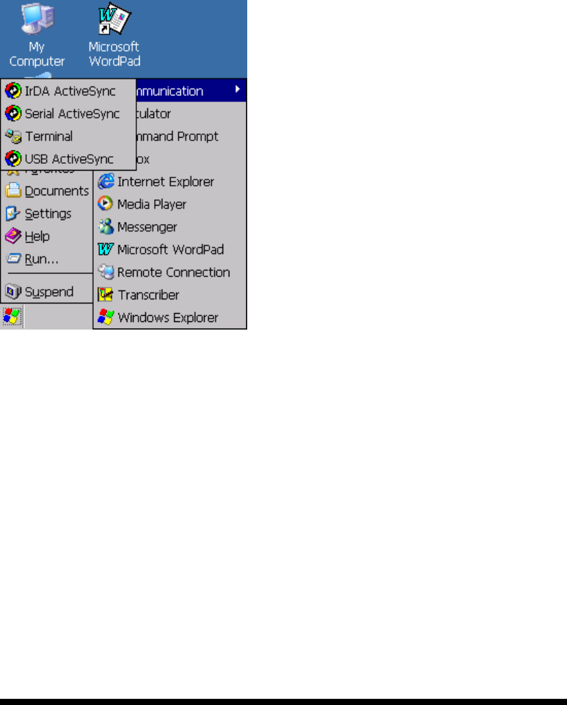
Transferring Files:
To transfer files, complete the
following steps on the host PC:
Select Start> Programs
>Communication >(IrDA,
Serial, or USB) Activesync.
Double-click on the selected
ActiveSync icon
After you have established a
connection with PDA, tap the
“Explore” button at the top of
the ActiveSync window ( or
select Explore from the File
menu).

4.2 Networking
Please see the 3.2.17 Owner, Table 3-16 Owner on page 3-50 for setting up the
network ID. And see the 2.5.6 Initiating a Network Connection to setup the
802.11b Wireless LAN for RF connecting.
P4-3