iWaylink IT7000PDT-W PDT (Portable Data Terminal) User Manual User s manual
Bitatek Co., Ltd. PDT (Portable Data Terminal) User s manual
UserManual.wiki
>
iWaylink
>
IT7000PDT W User Manual
Users Manual
Navigation menu
Upload a User Manual
Namespaces
Wiki Guide
HTML
PDF
Info
Views
User Manual
Discussion / Help
Navigation
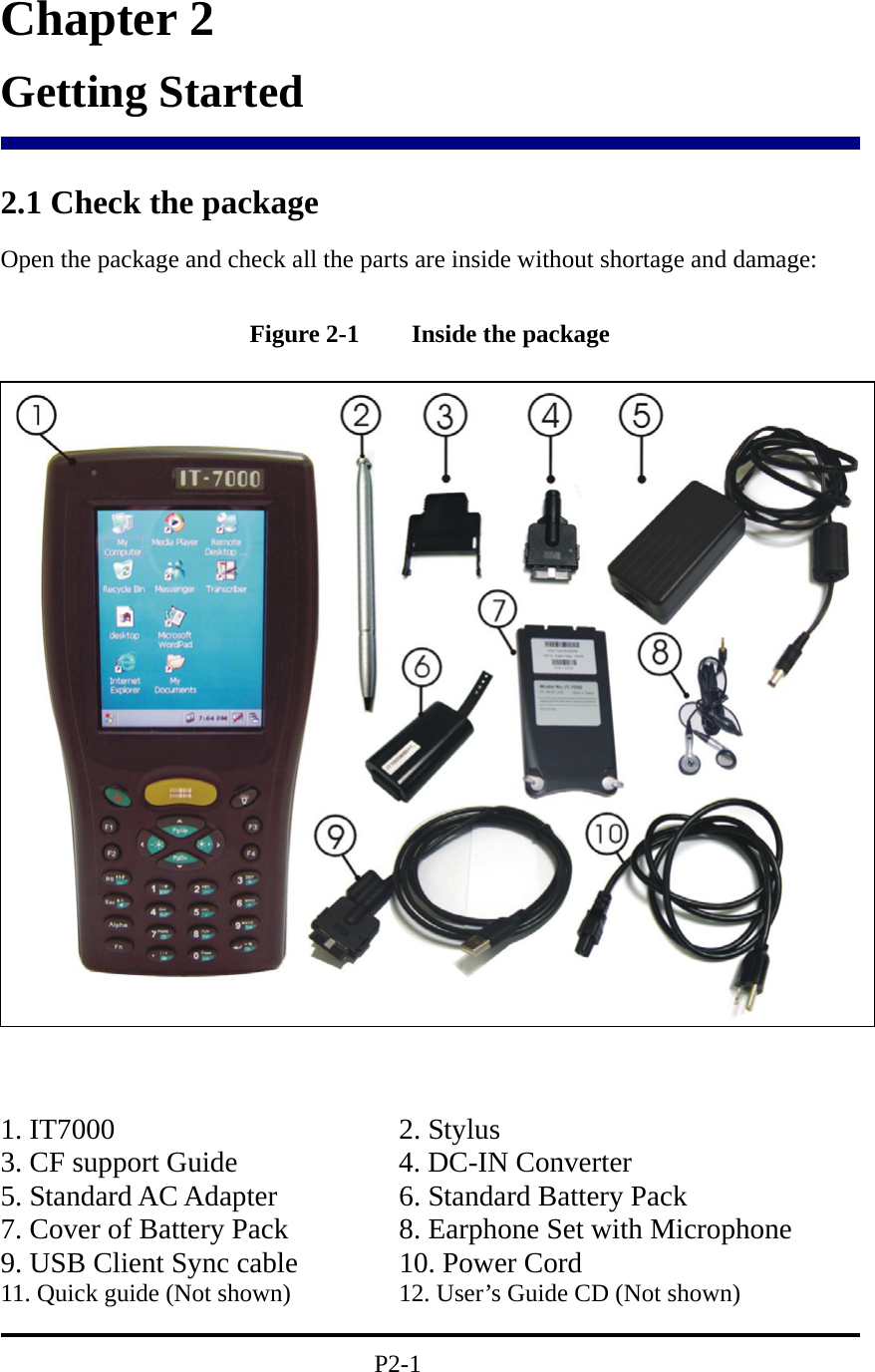
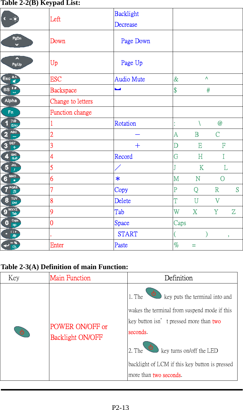
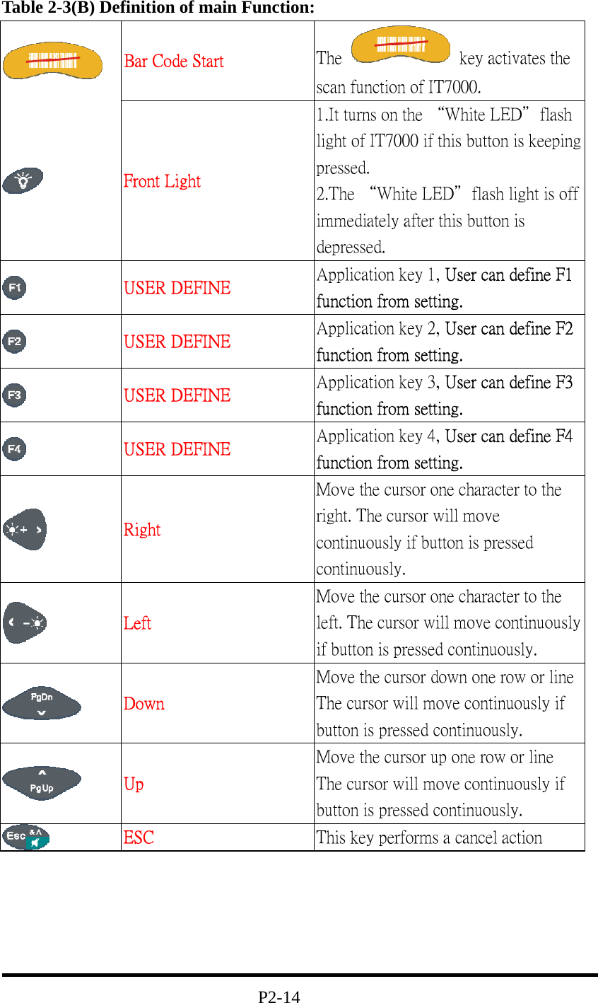
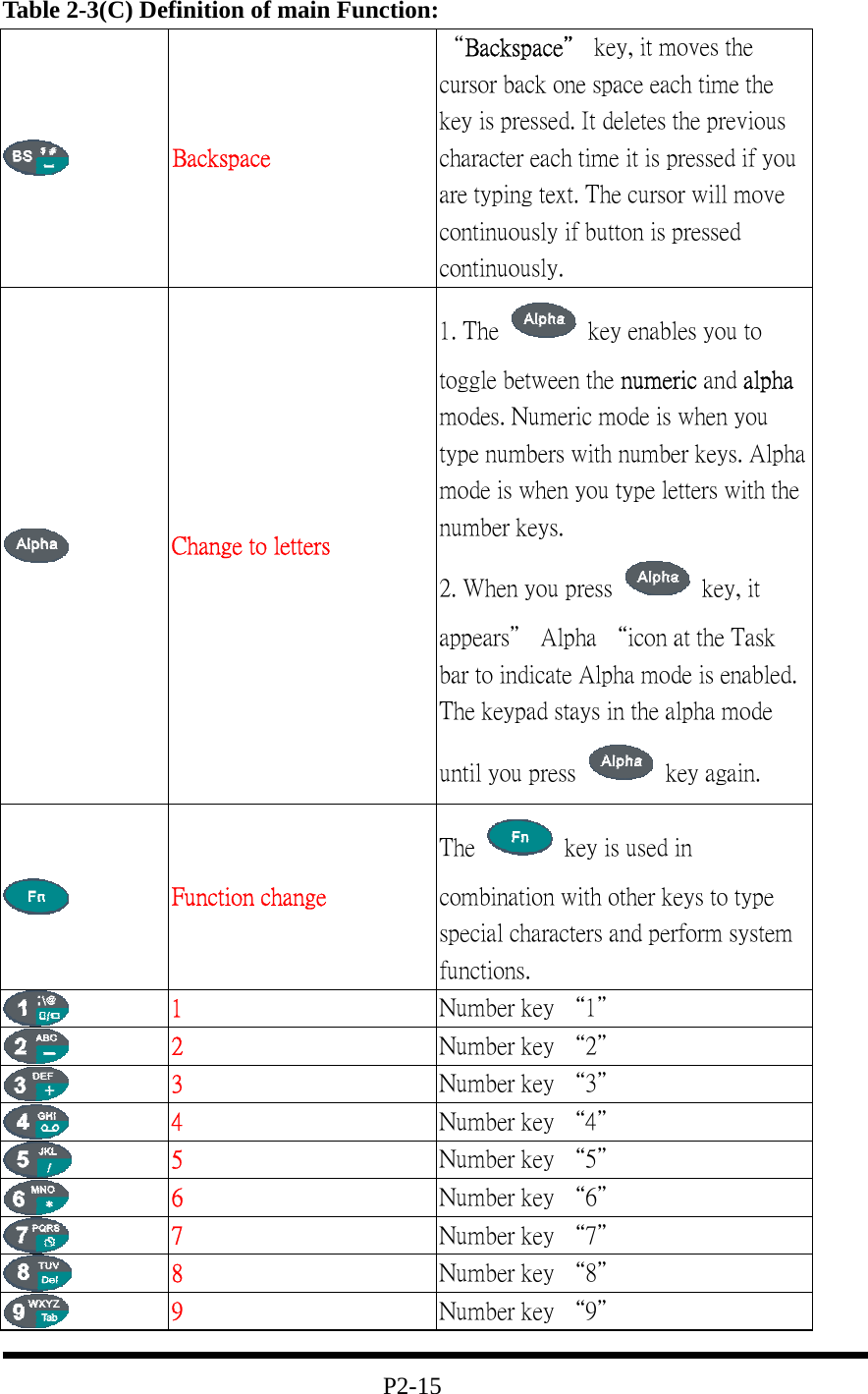
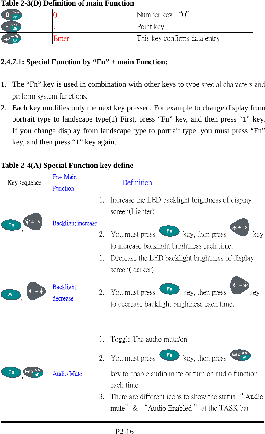
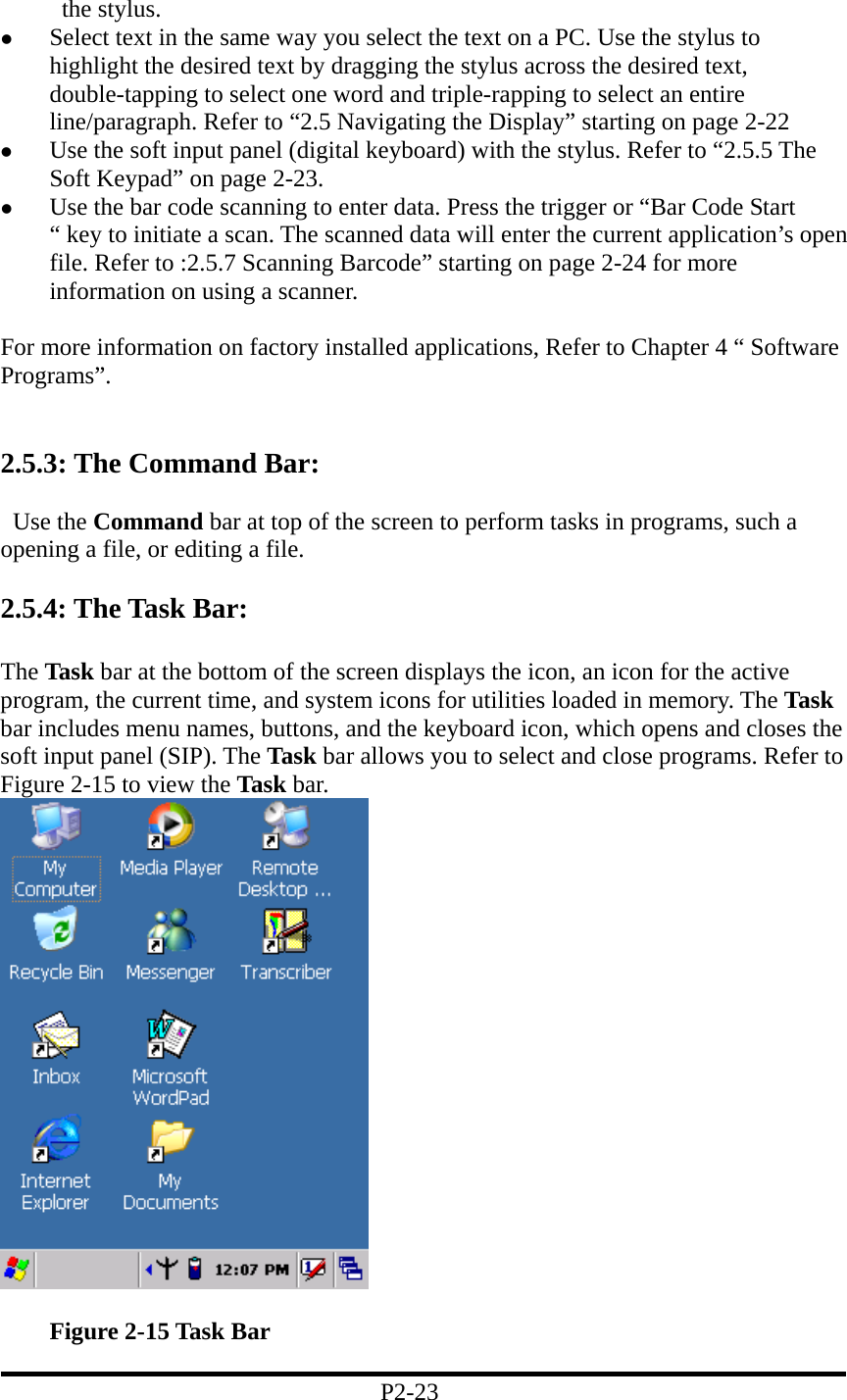
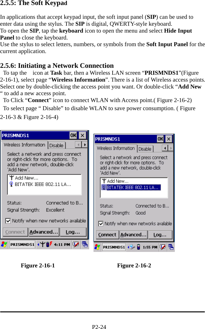
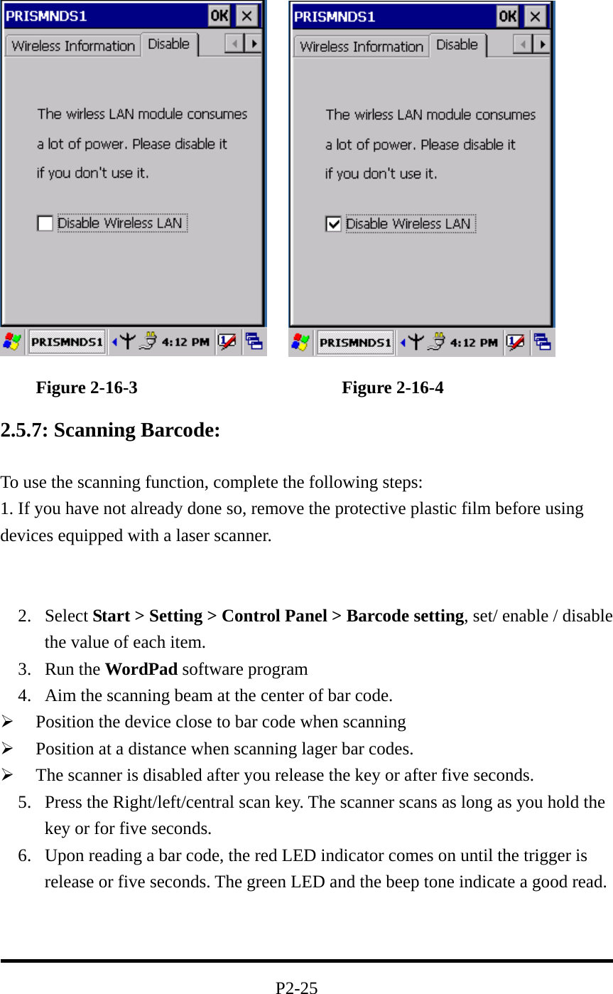
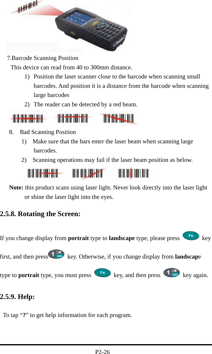
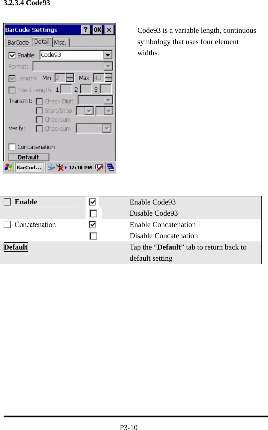
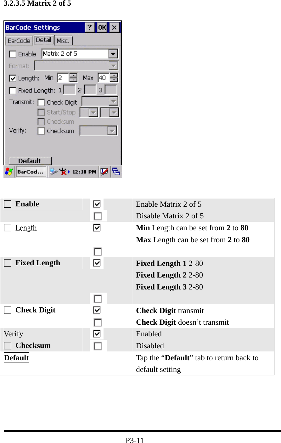
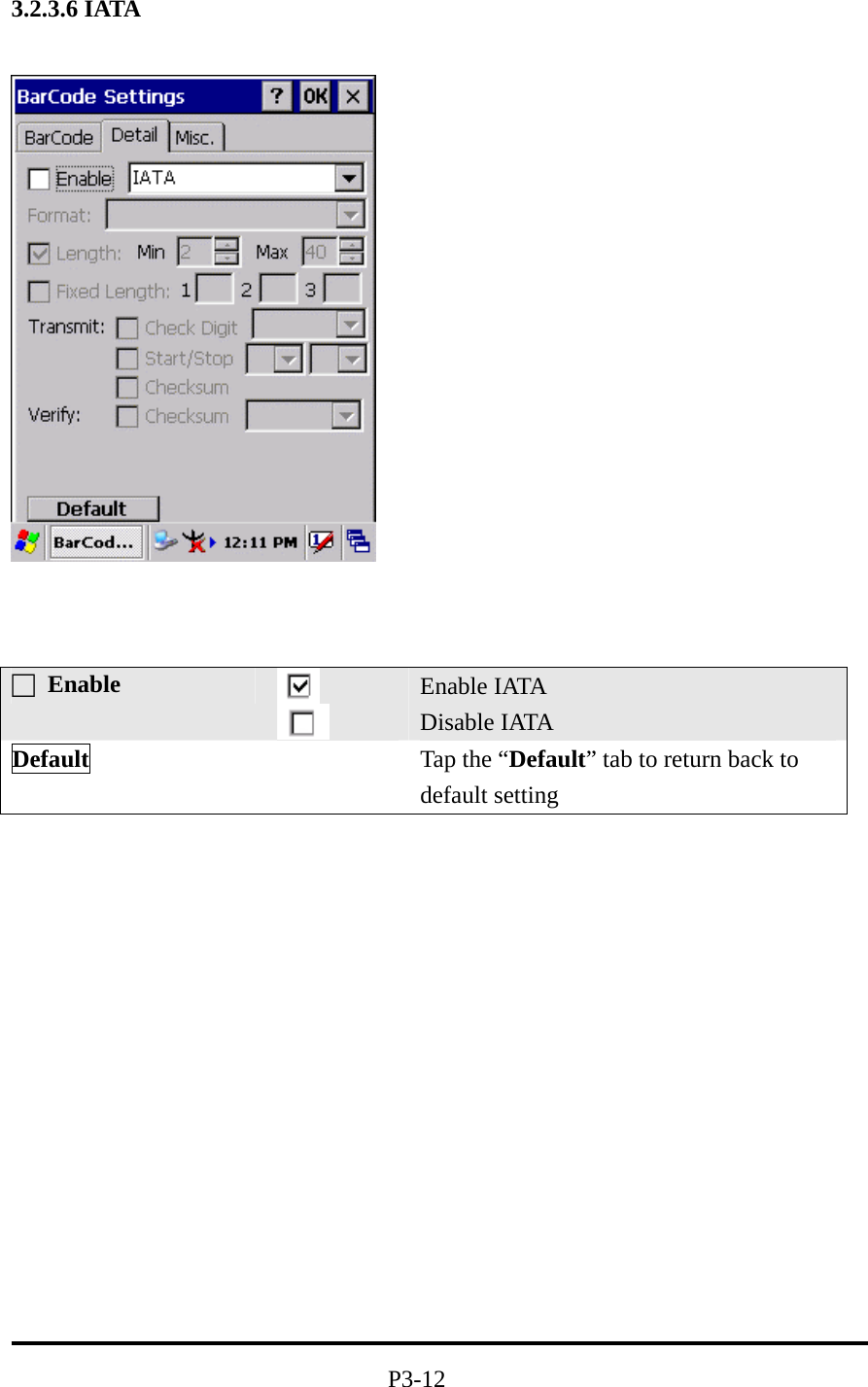
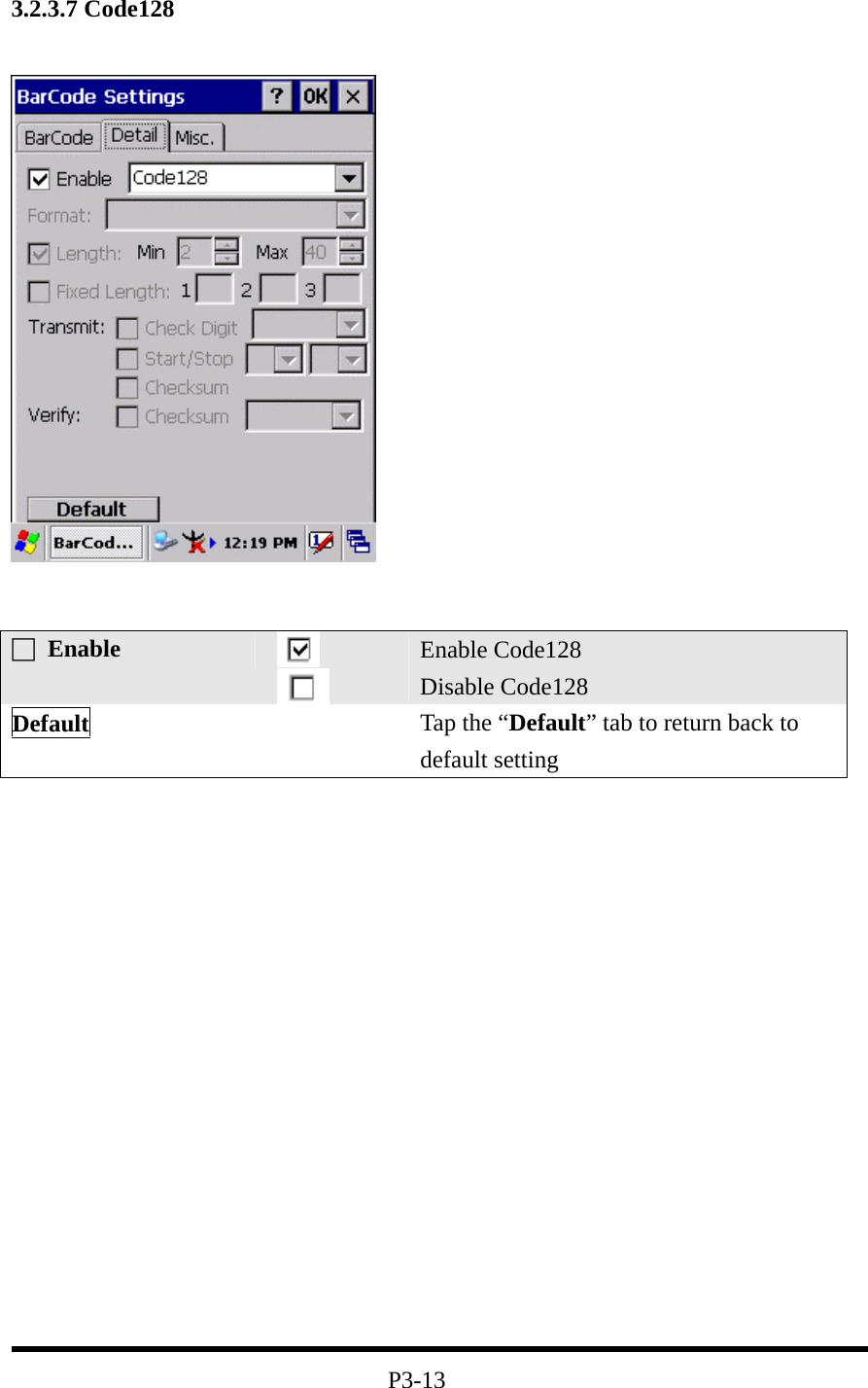
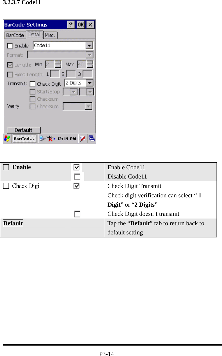
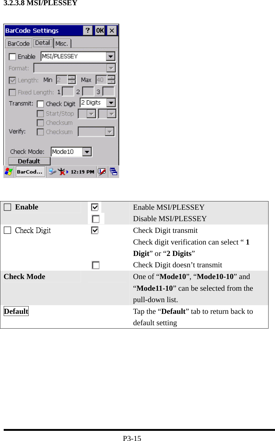
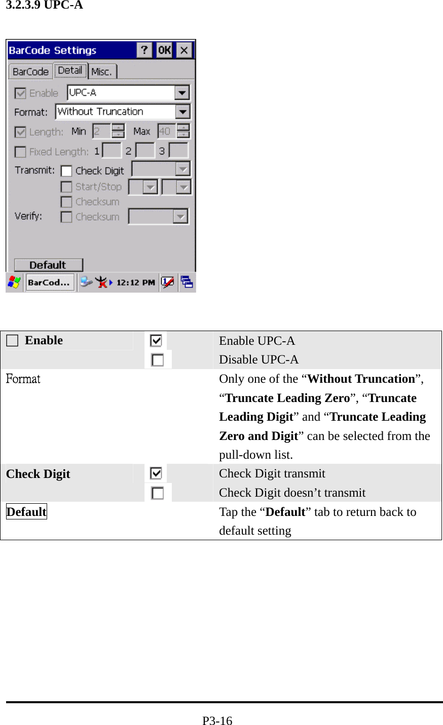
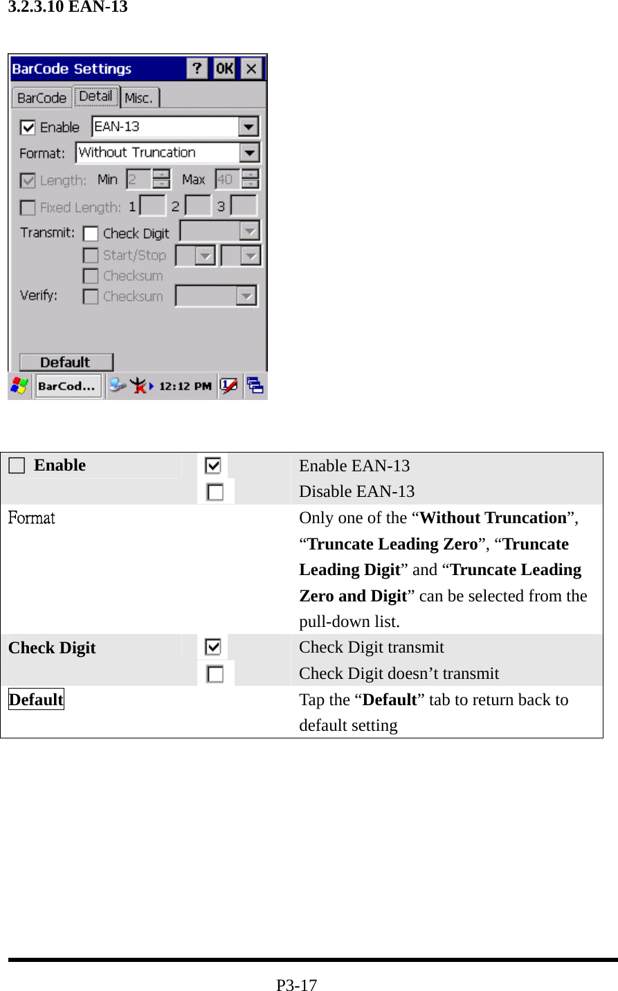
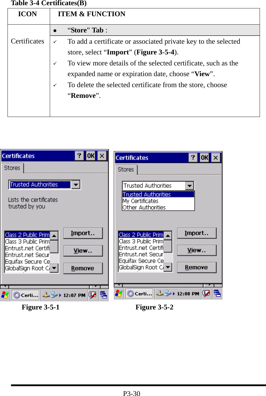
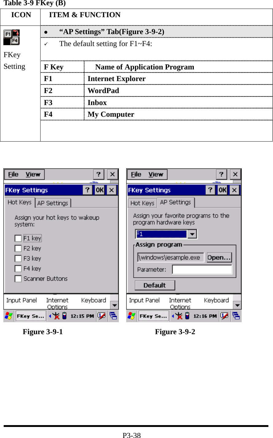
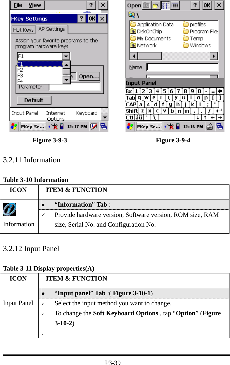
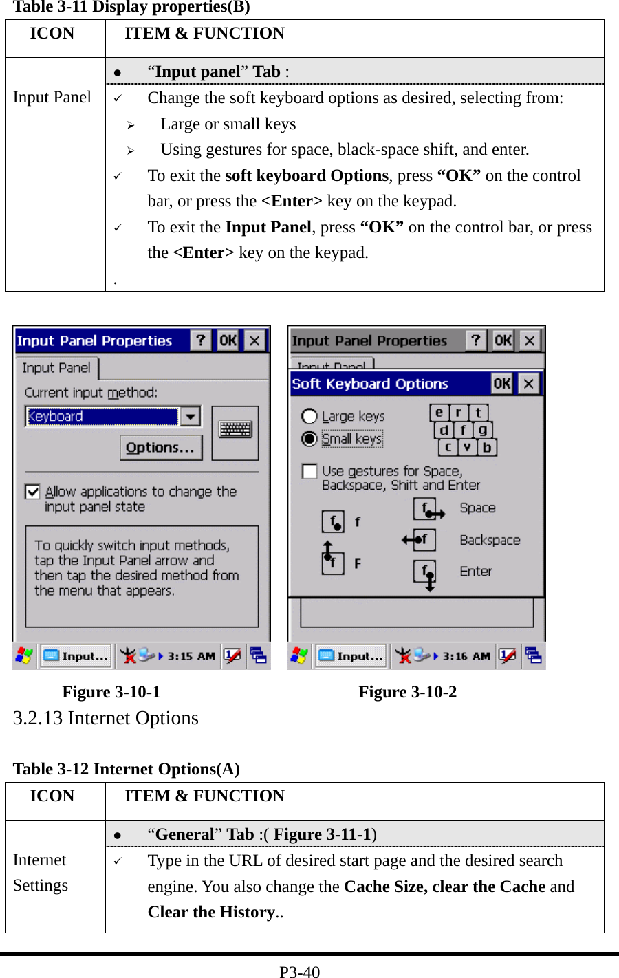
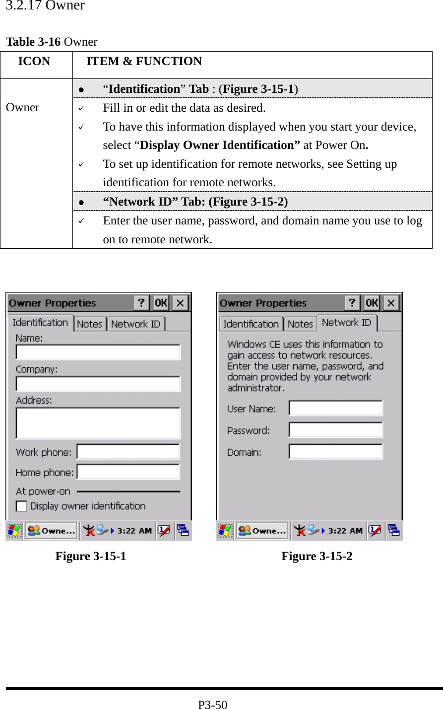
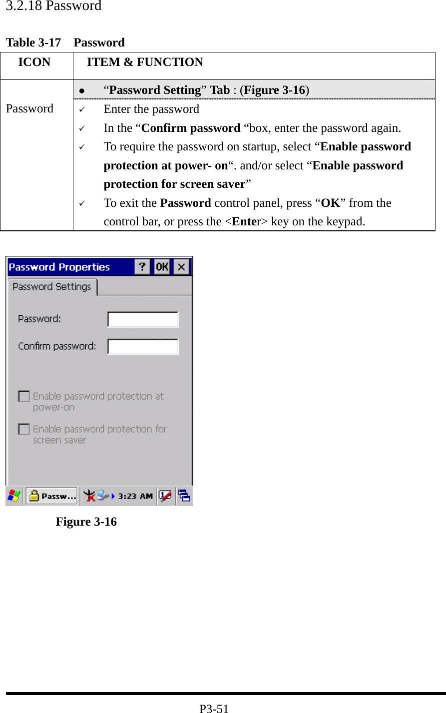
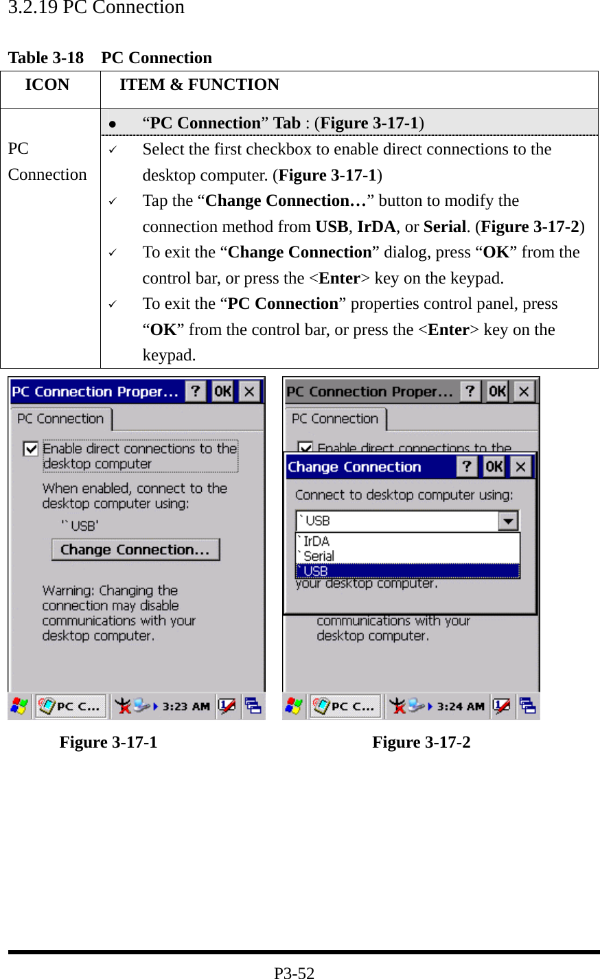
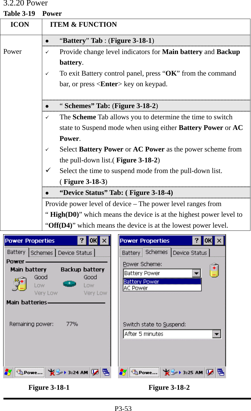
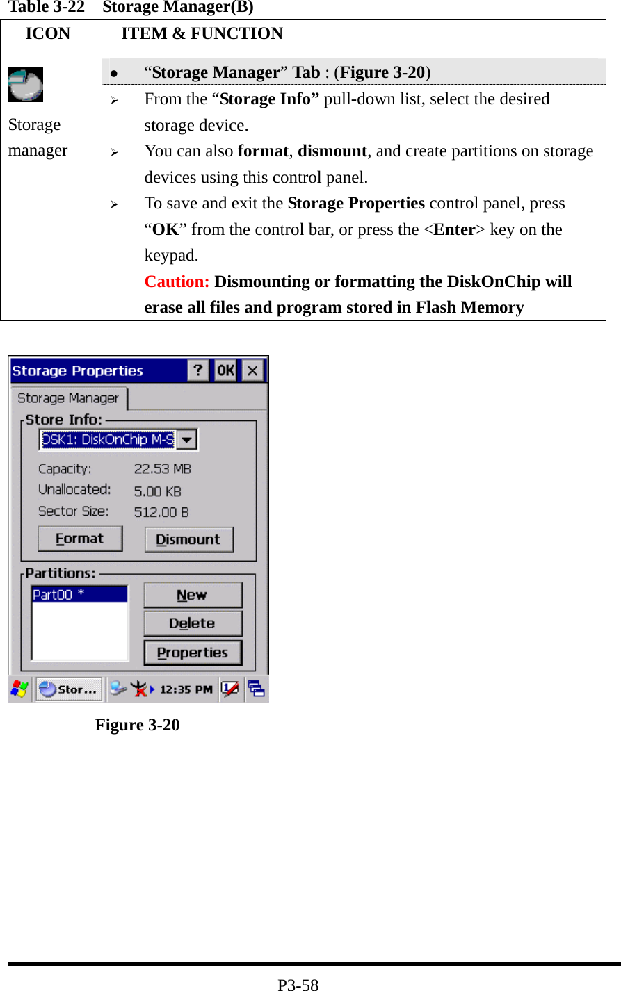
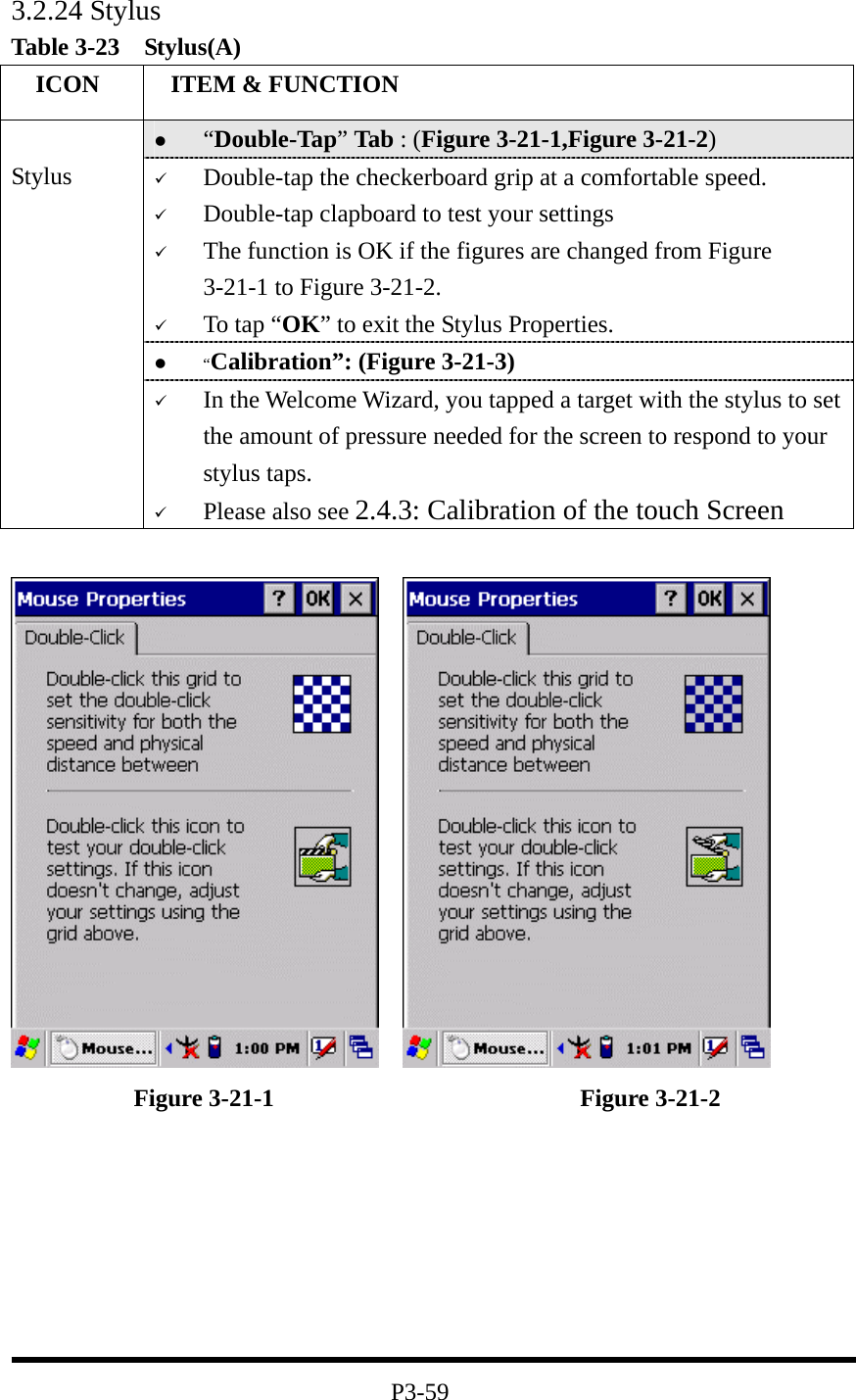
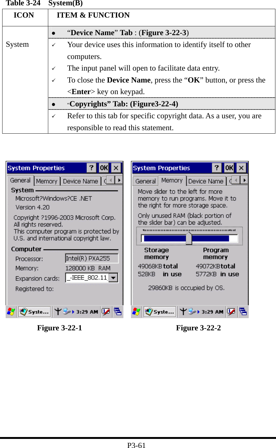
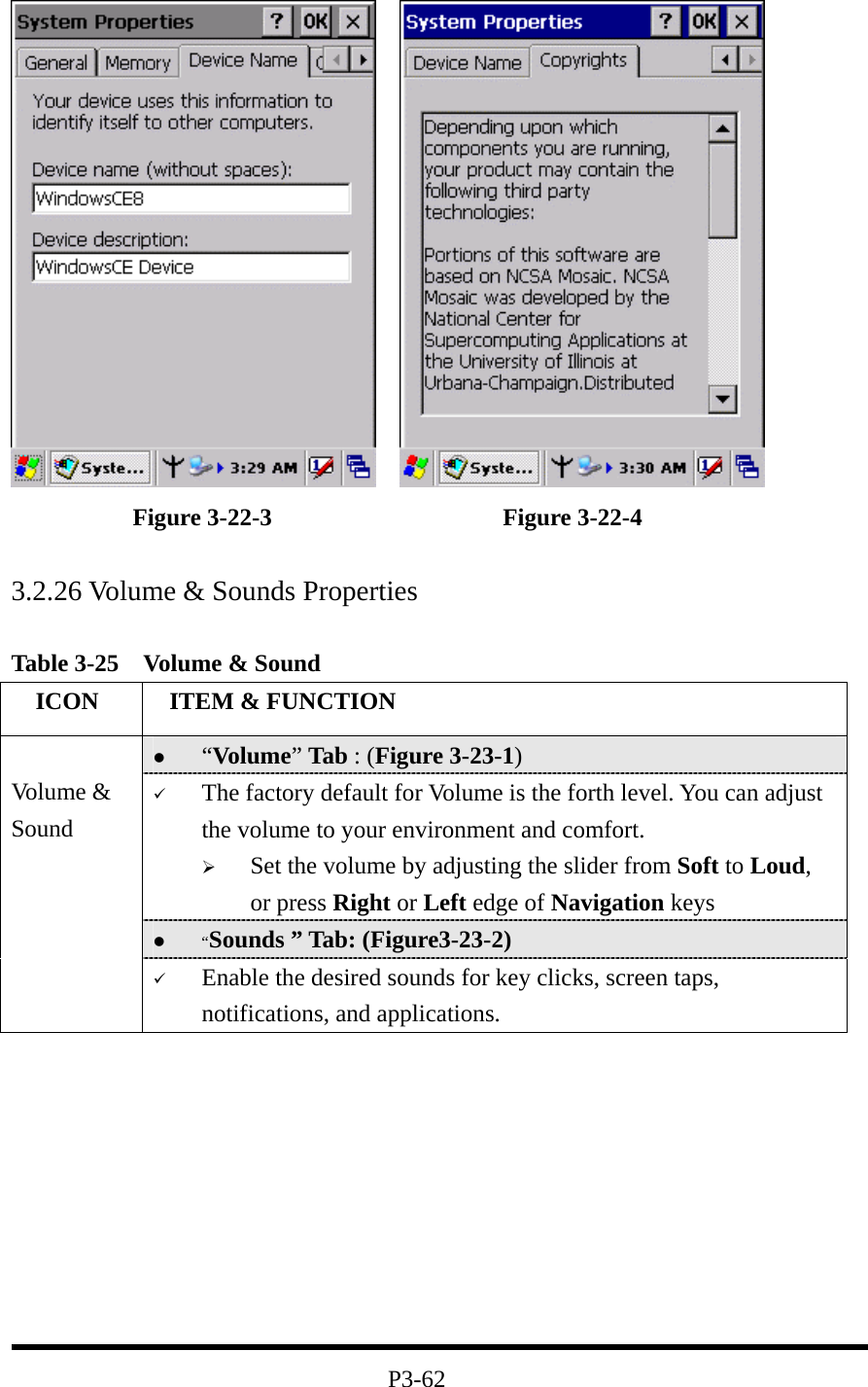
![2.5: Navigating the Display 2.5.1: Setting Time and Date: Figure 2-14 Date/Time properties 4. To change the time, select the hour, minute, seconds, or AM/PM and select the up arrow to increase the value; select /tape the down arrow to decrease the value. Or you can type a new value in the field. 5. Select your correct time zone from the pull-down list. 6. To automatically adjust the clock for Daylight Saving Time, enable the checkbox at the bottom of the screen. 7. Select Apply to make save your changes [and make additional modifications] or select OK to exit the Date/Time settings. 2.5.2: Entering the Data To select and open programs, select Start > Programs from the task bar to open a list of available programs. Or if the program has a icon on the desktop, double-tap to open it. There are several ways to enter data on the PDA once in an application: Use the keypad to enter alpha-numeric characters, Refer to “2.4.7 Using the keypad” on page 2-12. Use the stylus on the touch screen on page 2-6 for more information on using . P2-22 In the Date/Time options, you can change the year, month, date, time, time zone, or select automatic adjust for Daylight Saving Time. To set or change the date and time: 1. Select Start > Settings > Control Panel > Date/Time 2. Select the month to open a pull-down list of months or press the arrow buttons to either side of the month to increase or decrease the month. 3. To change the year, select the year or open a numeric dial. Select the up arrow to increase the value; select the down arrow to decrease the value. Or you can type a new value in the field.](https://usermanual.wiki/iWaylink/IT7000PDT-W/User-Guide-506900-Page-34.png)