id Systems MVAC30 OBDII tracking Device User Manual 055 00000889 RevB UTP1 0 installation
I.D. Systems Inc. OBDII tracking Device 055 00000889 RevB UTP1 0 installation
User Manual
UTP 1.0
INSTALLATION &
VERIFICATION INSTRUCTIONS
©2017 I.D. Systems, Inc.
055-00000889 Rev B
UTP 1.0 Installation & Verification Instructions
I.D. Systems Confidential and Proprietary
1
055-00000889 Rev A
Copyright © 2017 I.D. Systems, Incorporated. All Rights Reserved.
The material contained in this document is protected by the copyright and trade secret laws of
the United States and other countries. It may not be reproduced, distributed, or altered in any
fashion by any entity (either internal or external to I.D. Systems, except in accordance with
applicable agreements, contracts, or licensing, without the express written consent of the Brand
or Marketing Communications Director or the business management owner of the material.
Disclaimer and Limitations of Liability
The information contained in this Guide is subject to change without notice and should not be
construed as a specification.
NOTICE: This device complies with Part 15 of the FCC Rules and with Industry Canada
license-exempt RSS standard(s)].
Operation is subject to the following two conditions:
(1) this device may not cause harmful interference, and
(2) this device must accept any interference received, including interference that may
cause undesired operation.
Le présent appareil est conforme aux CNR d'Industrie Canada applicables aux appareils radio
exempts de licence. L'exploitation est autorisée aux deux conditions suivantes:
(1) l'appareil ne doit pas produire de brouillage, et
(2) l'appareil doit accepter tout brouillage radioélectrique subi, même si le brouillage est
susceptible d'en compromettre le fonctionnement.
NOTICE: Changes or modifications made to this equipment not expressly approved by
I.D. Systems may void the FCC authorization to operate this equipment.
To comply with FCC/IC RF exposure limits for general population / uncontrolled exposure, the
antenna(s) used for this transmitter must be installed to provide a separation distance of at least
20 cm from all persons and must not be co-located or operating in conjunction with any other
antenna or transmitter.

UTP 1.0 Installation & Verification Instructions
I.D. Systems Confidential and Proprietary
2
055-00000889 Rev A
I.D. Systems
www.id-systems.com/
Customer Support: 888-855-0913
UTP 1.0 Installation & Verification Instructions
I.D. Systems Confidential and Proprietary
3
055-00000889 Rev A
Table of Contents
1.
OVERVIEW .............................................................................................................................................. 4
2.
UTP 1.0 COMPONENTS ............................................................................................................................ 4
3.
REQUIRED TOOLS (NOT PROVIDED) .......................................................................................................... 4
4.
INSTALLATION STEPS ............................................................................................................................... 5
5.
LED INDICATORS ................................................................................................................................... 11
6.
INSTALLING ON MULTIPLE VEHICLES AT THE SAME TIME ......................................................................... 12
7.
UNINSTALLING THE UTP 1.0 ................................................................................................................... 13
UTP 1.0 Installation & Verification Instructions
I.D. Systems Confidential and Proprietary
4
055-00000889 Rev A
1. Overview
• This document details UTP 1.0 (remote vehicle monitoring and control hardware) installation
and verification process.
• Failure to follow the installation and verification processes may result in improper device
operation and/or payment dispute for installation services.
• Contact Avis Budget Group customer support at xxxxxxxxxx with any questions regarding
installation and/or verification.
• This document can be download in electronic format from http://ww2.id-
systems.com/support/training/VMS_Guides/UTP1.0_installation_Rev1.pdf.
• Any recommendations and/or corrections should be forwarded to dflanagin@id-
systems.com.
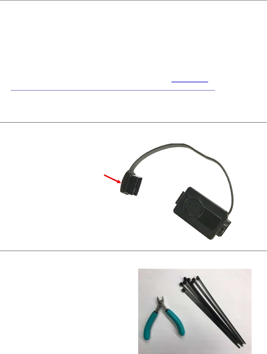
2. UTP 1.0 Components
• UTP 1.0 Enclosure
• Cable
• OBD-II Connector
• LED area
3. Required Tools (Not Provided)
• Five 8” tie wraps
• 4.5” wire cutter
Enclosure
Cable
OBD
-
II Connector
LED area
UTP 1.0 Installation & Verification Instructions
I.D. Systems Confidential and Proprietary
5
055-00000889 Rev A
4. Installation Steps
NOTE: In all cases, safe location and secure mounting of the UTP 1.0 device is the
installer’s primary concern.
Installer is responsible for ensuring the UTP 1.0 device is safely and securely
mounted and does not interfere with vehicle operation.
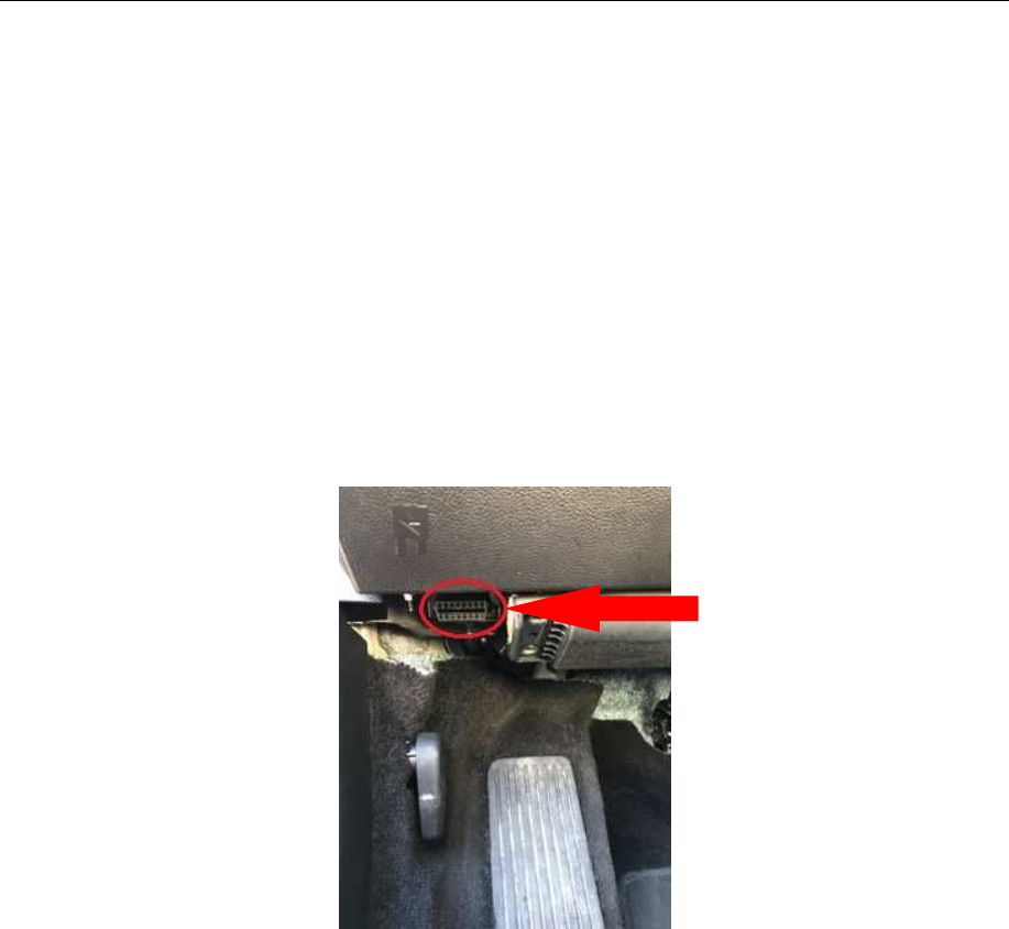
1) Locate the vehicle’s OBD-II port (usually located on the bottom left of the driver’s side
dash).
• Depending on the vehicle make/model, sometimes the OBD-II port is located in the
bottom middle or bottom right of the driver’s side, under the dash area.
• With Kia and Hyundai vehicles, the OBD-II port is usually located on the front left
side of dash through a small access panel.
Example Location of OBD Port (varies by vehicle model)
2) Turn the engine on and roll down the driver’s side window, leaving the car door open
prior to installation.
UTP 1.0 Installation & Verification Instructions
I.D. Systems Confidential and Proprietary
6
055-00000889 Rev A
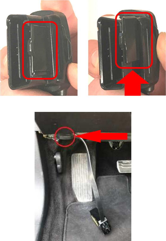
3) Make sure the OBD-II connector latch is in the “open” position, then plug OBD-II
connector into the vehicle OBD-II port. Make sure the connector is seated all the way
down. After plugging it in, move the latch back to the closed position.
Connector Latch Closed Connector Latch Open
UTP 1.0 plugged into OBD-II port
UTP 1.0 Installation & Verification Instructions
I.D. Systems Confidential and Proprietary
7
055-00000889 Rev A
4) If the vehicle alarm should sound during installation, use the key fob to unlock the doors
and disable the alarm.
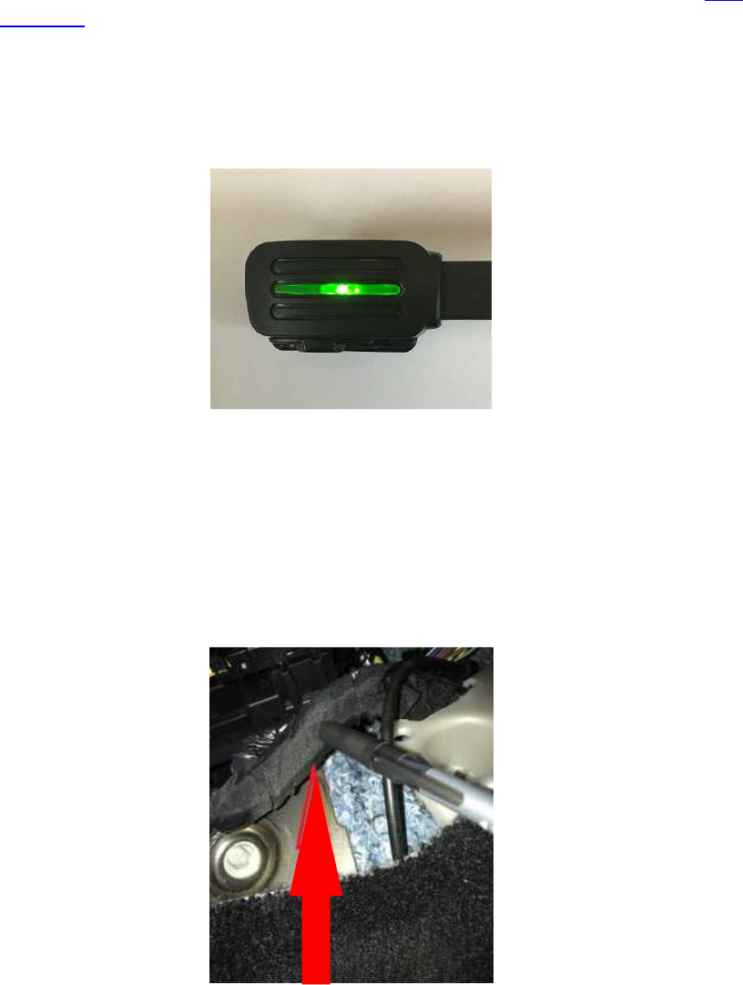
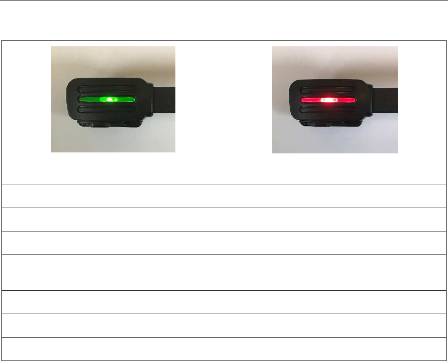
5) Once the UTP 1.0 connector is plugged in, the green LED light on the connector will
begin to flash. It will take approximately 3.5 minutes to in-fleet successfully. (See LED
Indicators for more information.)
• LED Pattern: Quick blink for 3 minutes, then periodic flashing for 30 seconds before
the LED turns solid green.
• If the LED on the UTP 1.0 connector turns red, make sure the car/vehicle is a
certified make/model.
6) When the UTP 1.0 in-fleets successfully (the LED turns solid green), the enclosure is
ready to be routed under the dash and tie-wrapped to a wire harness. When searching
for a wire harness, locate a thick, immovable location.
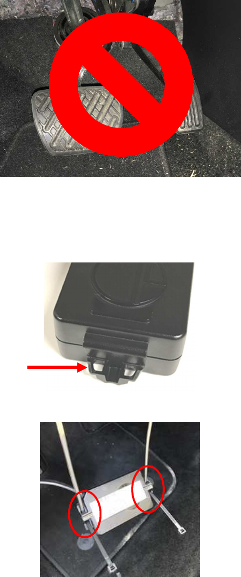
• Avoid installing the UTP 1.0 in the brake or gas pedal areas. Also, avoid installing on
loose wire harnesses.
Locate a wire harness
Solid green LED indicates successful in-fleet
UTP 1.0 Installation & Verification Instructions
I.D. Systems Confidential and Proprietary
8
055-00000889 Rev A
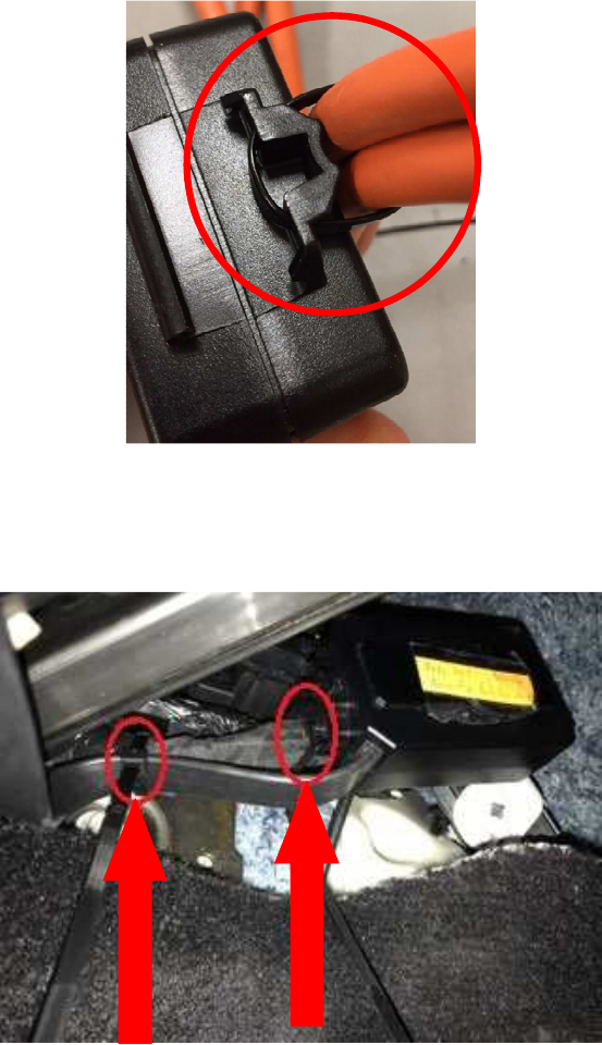
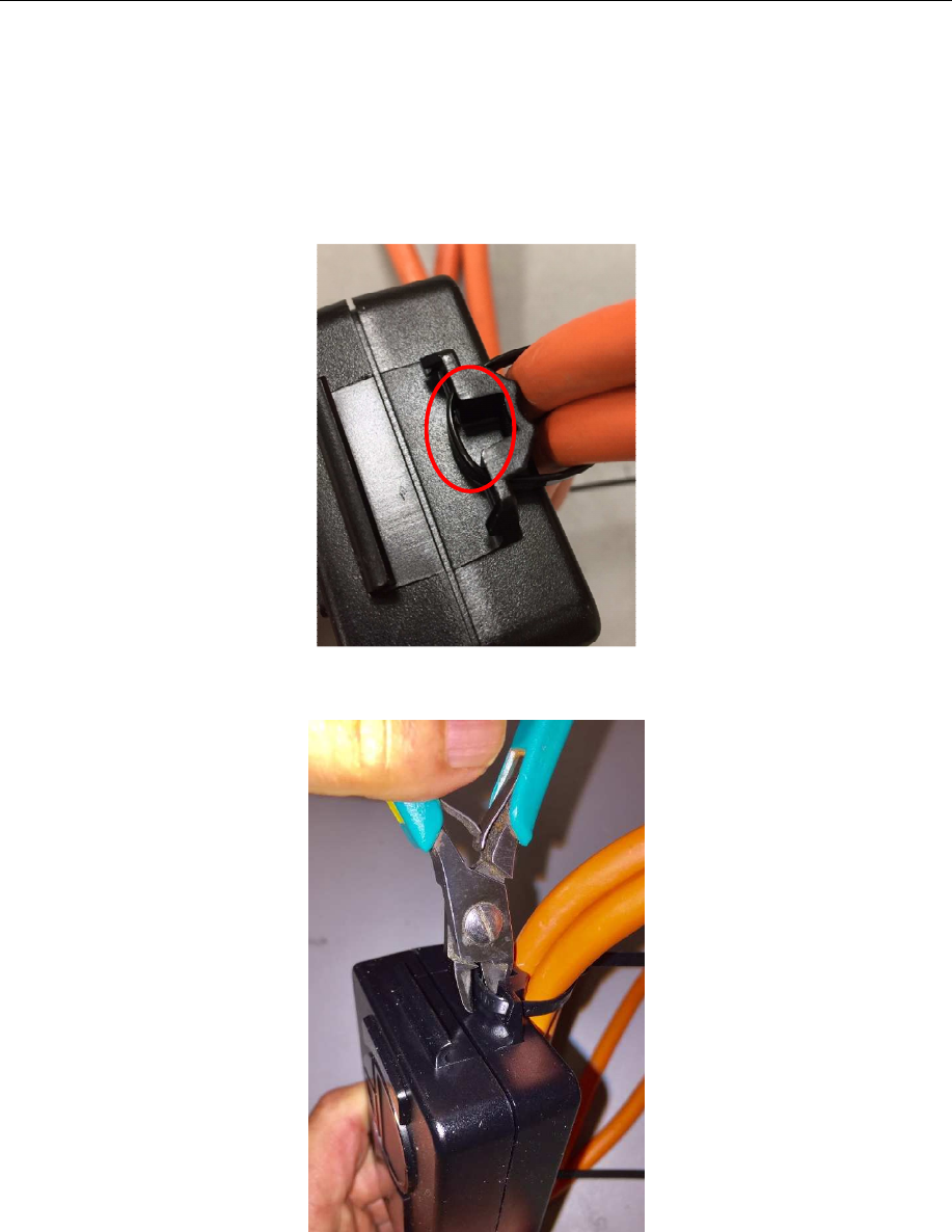
7) When tie wrapping the UTP 1.0 to the vehicle harness, wire tie both sides of the UTP 1.0
enclosure.
Tie wraps fed through inserts on both
ends of UTP 1.0
Location of tie-wrap insert on enclosure
Do not install near brake / gas pedal area
UTP 1.0 Installation & Verification Instructions
I.D. Systems Confidential and Proprietary
9
055-00000889 Rev A
UTP 1.0 securely tie wrapped onto wire harness. In this
example, one side of the UTP 1.0 is tie wrapped and UTP cable
is tie wrapped onto the wire harness as well.
UTP 1.0 mounting feature and secured
to vehicle harness
UTP 1.0 Installation & Verification Instructions
I.D. Systems Confidential and Proprietary
10
055-00000889 Rev A
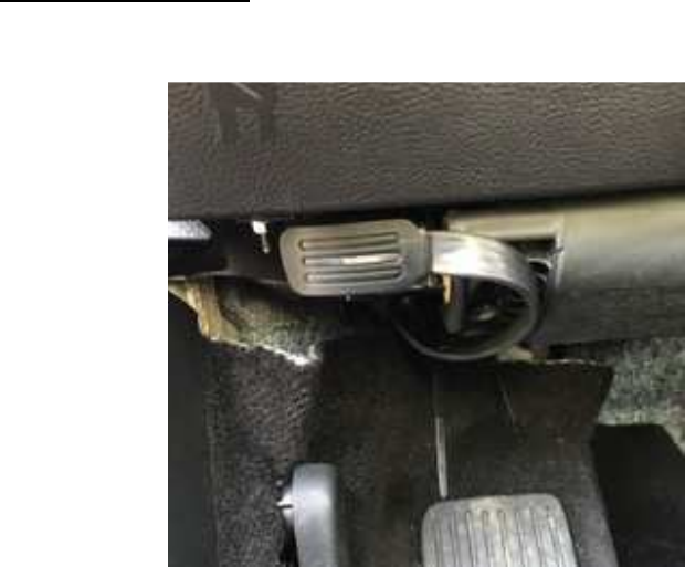
8) Final Install Validation: Make sure the UTP 1.0 enclosure is tucked in behind the panel
and not visible to the customer. Double check to make sure the UTP 1.0 is tie wrapped
securely to a wire harness and away from the gas/brake pedal area.
UTP 1.0 installed on 2017 Ford Fusion. UTP is routed
and tie wrapped onto a wire harness behind the panel.
UTP 1.0 Installation & Verification Instructions
I.D. Systems Confidential and Proprietary
11
055-00000889 Rev A
5. LED Indicators
GREEN LED
RED LED
Fast blink = firmware download Fast blink = non-certified vehicle
Slow blink = installing Slow blink = no cellular
Solid on = install successful Solid on = install failure
If both LEDs are…
OFF after install = Normal
OFF at install = No power
ON = Fatal exception

UTP 1.0 Installation & Verification Instructions
I.D. Systems Confidential and Proprietary
12
055-00000889 Rev A
6. Installing on Multiple Vehicles at the Same Time
The following process is recommended to speed the overall installation when installing UTP 1.0
devices on multiple vehicles at the same time.
1) Arrange up to 10 cars side-by-side with enough room to open driver-side doors without
hitting the adjacent vehicle.
2) Starting with the first vehicle:
• Turn vehicle ignition on, roll down driver-side window, and leave driver door open.
• Plug the UTP 1.0 unit into the OBD-II port and leave UTP 1.0 hanging down while
waiting for the device to complete the In-Fleet process.
• Proceed with remaining vehicles
3) Go back to the first car and make sure the LED on the UTP connector has turned solid
green (indicating successful In-Fleet).
4) Once the UTP 1.0 LED has turned solid green, use two wire ties to attach the UTP 1.0 to a
wire harness under the dash panel.
5) Make sure the UTP 1.0 OBD-II plug is fully seated into the OBD-II port and the slide is in
the locked position.
6) Repeat the attachment and lock verification process for the remaining vehicles.
UTP 1.0 Installation & Verification Instructions
I.D. Systems Confidential and Proprietary
13
055-00000889 Rev A
7. Uninstalling the UTP 1.0
To safely uninstall the UTP 1.0, follow these steps:
1) Use the built-in tie wrap cutting feature on both side of the UTP 1.0 when
cutting/removing tie wraps, so as not to damage the wire harness or the UTP 1.0
enclosure. See photos below.
Carefully cut tie wrap without damaging harness or the
UTP 1.0 enclosure
UTP 1.0 Installation & Verification Instructions
I.D. Systems Confidential and Proprietary
14
055-00000889 Rev A
2) Move the OBD-II connector latch to the open position and unplug the OBD-II connector
from the vehicle OBD-II port.
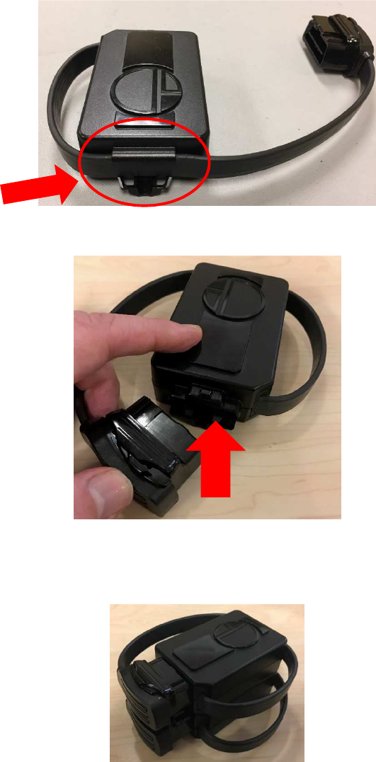
3) Coil the UTP 1.0 cable, securing it to the enclosure, and fasten the OBD-II connector onto
the receptacle on the enclosure. Move the latch to the closed position.
4) Stack UTP 1.0 devices (as pictured below).
Coil the cable, securing it to the enclosure
Fasten OBDII connector to enclosure