id Systems VAC03 Vehicle Asset Communicator User Manual 900 0144 02 Users Guide v3 1
I.D. Systems Inc. Vehicle Asset Communicator 900 0144 02 Users Guide v3 1
Manual

I.D. SYSTEMS, INC.
VAC™ – Vehicle Asset Communicator™
A Wireless Fleet Management Device
VAC
User’s Guide
Version 3.1.x
VAC™ – A WIRELESS FLEET MANAGEMENT DEVICE
VAC – User’s Guide
VAC™ IDS Gateway™
IDS WAN Console™
© I.D. Systems, Inc.
1 University Plaza • 6th Floor
Hackensack, NJ 07601
Phone 201.996.9000 • Fax 201.996.9144
www.id-systems.com

Preface
This manual is a user’s guide for the VAC (Vehicle Asset Communicator), a Wireless Fleet Management
Device developed by I.D. Systems, Inc. This guide provides the instruction necessary for someone to
install, operate and maintain the VAC device in a vehicle. Note: This user’s guide may change without notice due to
enhancements or changes to VAC.
Related Documents
Vehicle Survey (Doc. #: 026-1000-01)
Publication History
Version Date Changes
2.5.x 9.18.02 Initial
2.6.x 10.25.02 New Modules: Seatbelt monitor & Battery rotation, new
installation screens and color coded connector labels
2.7.x 01-03-03 Add Ext Reader Test, Ext LED Test, Security Features
2.8.x 08-07-03 Add Critical OSHA Shutdown, Blank VAC In Motion
3.0.x 11-03-03 Now Using New Enclosure
3.1.x 03-11-04 O/T versions for new enclosure
Disclaimer and Limitation of Liability
I.D. Systems, Inc. assumes no responsibility for any damage or loss resulting from the use of its products
or services. I.D. Systems assumes no responsibility for any loss or claims by third parties, which may arise
through the use of its products or services.
The information disclosed herein is the exclusive property of I.D. Systems and no part of this information
may be reproduced or transmitted in any form or by any means including electronic storage, reproduction,
execution or transmission without the prior written consent of I.D. Systems. The information contained
in this document is subject to change without notice and should not be construed as a commitment by
I.D. Systems unless such commitment is expressly given in writing.

FCC Compliance Statement
Compliance Statement (Part 15.19)
This device complies with Part 15 of the FCC Rules. Operation is subject to the following two
conditions:
1. This device may not cause harmful interference, and
2. This device must accept any interference received,
including interference that may cause undesired operation.
Warning (Part 15.21)
Changes or modifications not expressly approved by the party responsible for compliance could void the
user’s authority to operate the equipment.
Compliance Statement (Part 15.247)
This device complies with Part 15.247 of the FCC rules. Operation is subject to the following condition:
To comply with FCC’s RF exposure limits for general population/uncontrolled exposure, the antenna(s)
used for this transmitter must be installed to provide a separation distance of atleast 20cm from all
persons and must not be co-located or operating in conjunction with any other antenna or transmitter.

TableofContents
I.D. Systems, Inc. One University Plaza, Hackensack, NJ 07601 000-0144-01
Tel: 201-996-9000; Fax 201-996-9144; email: support@id-systems.com Page 5 of 41
Table of Contents
TABLE OF CONTENTS ......................................................................................................................................................................................... 5
INTRODUCTION ...................................................................................................................................................................................................... 7
SYSTEM OVERVIEW ................................................................................................................................................................................................ 7
INSTALLATION ....................................................................................................................................................................................................... 9
WARNINGS ............................................................................................................................................................................................................ 9
STANDARD HARDWARE FOR INSTALLATION .................................................................................................................................................... 9
TOOLS REQUIRED FOR INSTALLATION (NOT SUPPLIED) ............................................................................................................................. 9
SYSTEM CONNECTIONS OVERVIEW ................................................................................................................................................................. 10
INSTALLATION SUMMARY ................................................................................................................................................................................... 10
BEFORE STARTING THE INSTALLATION .......................................................................................................................................................... 10
INSTALLING THE VAC (AND OPTIONAL ID READER) ................................................................................................................................... 11
Selecting the VAC Mounting Location .............................................................................................................................................................. 11
Mounting the VAC ............................................................................................................................................................................................. 11
INSTALLING VAC-TO-PCM HARNESS ............................................................................................................................................................ 12
Vehicle Cable Harness ...................................................................................................................................................................................... 12
Selecting the System’s Power and Ground Connections .................................................................................................................................. 12
FINISHING THE INSTALLATION .......................................................................................................................................................................... 13
System Configuration ........................................................................................................................................................................................ 13
STANDARD VAC OPERATION ....................................................................................................................................................................... 14
VAC OVERVIEW .................................................................................................................................................................................................... 14
GENERAL OPERATION .......................................................................................................................................................................................... 15
BASIC OPERATION: LCD, KEYPAD, ID READER AND LEDS .................................................................................................................... 16
VAC Display and Keypad Basics ...................................................................................................................................................................... 16
ID Reader .......................................................................................................................................................................................................... 16
Menu Selection Mode ........................................................................................................................................................................................ 16
Digit Entry Mode............................................................................................................................................................................................... 17
ACCESS CONTROL (ALL USERS): LOGGING ON AND OFF THE VEHICLE ............................................................................................... 18
Access Control Overview .................................................................................................................................................................................. 18
Logging onto the VAC ....................................................................................................................................................................................... 19
Denial of Login ................................................................................................................................................................................................. 21
NOTE: Repeated failure to log into the VAC will trigger an alert on the ARDCS which can be emailed or sent by pager to specified
personnel (See ARDCS User’s Guide). ............................................................................................................................................................ 22

VACUser’sGuide
I.D. Systems, Inc. One University Plaza, Hackensack, NJ 07601 000-0144-01
Tel: 201-996-9000; Fax 201-996-9144; email: support@id-systems.com Page 6 of 41
Logging Off of the VAC ..................................................................................................................................................................................... 23
ELECTRONIC OSHA SAFETY CHECKLISTS (ALL USERS) .......................................................................................................................... 23
OSHA Question Mode ....................................................................................................................................................................................... 24
Critical OSHA Shutdown (Optional) ................................................................................................................................................................ 26
TWO-WAY TEXT PAGING (ALL USERS) .......................................................................................................................................................... 26
Viewing and Responding to Text Pages ............................................................................................................................................................ 27
VEHICLE UTILIZATION MONITORING (ALL USERS) ..................................................................................................................................... 29
MOTION SAFETY FEATURE (OPTIONAL – STANDARD AND MASTER USERS) ........................................................................................ 30
BATTERY ROTATION (OPTIONAL MODULE - ALL USERS) .......................................................................................................................... 30
Battery Request: ................................................................................................................................................................................................ 31
Battery Validation: ............................................................................................................................................................................................ 32
Battery Request Troubleshooting: .................................................................................................................................................................... 33
SECURITY MODULE (OPTIONAL MODULE - ALL USERS) ............................................................................................................................ 33
GRANTING TEMPORARY ACCESS (MASTER USERS) ................................................................................................................................... 33
APPENDIX A............................................................................................................................................................................................................ 35
ELECTRICAL ............................................................................................................................................................................................................ 35
MEMORY/OTHER.................................................................................................................................................................................................... 35
COMMUNICATION .................................................................................................................................................................................................. 35
USER INTERFACE .................................................................................................................................................................................................. 36
ENVIRONMENTAL .................................................................................................................................................................................................. 37
MOUNTING .............................................................................................................................................................................................................. 37
APPENDIX B............................................................................................................................................................................................................ 38
VAC™ ERROR CODE GUIDE .............................................................................................................................................................................. 38
Error Code: E3301 ........................................................................................................................................................................................... 38
APPENDIX C............................................................................................................................................................................................................ 39
WARRANTY INFORMATION .................................................................................................................................................................................. 39
Limited Warranty .............................................................................................................................................................................................. 39
This Warranty Does Not Cover: ....................................................................................................................................................................... 39
General Provisions: ........................................................................................................................................................................................... 40
To Get Warranty Service or Returned Material Authorization: ....................................................................................................................... 40

Introduction
I.D. Systems, Inc. One University Plaza, Hackensack, NJ 07601 000-0144-01
Tel: 201-996-9000; Fax 201-996-9144; email: support@id-systems.com Page 7 of 41
Introduction
This manual is a user’s guide for the VAC (Vehicle Asset Communicator), a Wireless Fleet Management
Device developed by I.D. Systems. This guide will introduce the reader to the VAC and to I.D. Systems’
Fleet Management solution. In addition, this guide also includes information about VAC installation
procedures, installation options, operator instructions, maintenance procedures, and troubleshooting. The
owner and user of a VAC can use this guide to understand how a VAC works and how to interact with it.
The Introduction section covers general information about the IDS Fleet Management System, and what
part the VAC device plays in the system. Users of the IDS Fleet Management System should familiarize
themselves with this information to better understand the detailed instructions in this guide.
The Installation section provides detailed procedures and guidelines for hardware installation.
Electricians, mechanics or maintenance persons responsible for VAC installation or troubleshooting
should familiarize themselves with this hardware installation process. This will allow them a better
understanding of the interface between the VAC and the vehicle being managed. In addition, those who
perform vehicle maintenance will better understand the implications of parts replacement or rewiring.
Finally, VAC troubleshooting is more easily understood with an understanding of hardware installation
procedures and guidelines. In order to complete VAC installation, maintenance user software, covered in
the VAC Operation section is required.
The Standard VAC Operation section explains how the user interacts with the VAC user interface
(keypad, display and ID reader). As a mini-computer, the VAC is an interactive device requiring an
operator to interact with it. Standard operators (vehicle drivers) must familiarize themselves with the
section on Basic Operation, Access Control, Electronics, OSHA Checklists, and Two-Way Text Paging,
either through reading the Guide, or through hands-on training. Floor supervisors with special system
privileges (Master Users) should also become familiar with the Master User features.
The appendices include additional information for those who have purchased or who maintain the VAC.
Appendix A details the physical specifications of the system, which is useful for those who wish to
understand how the VAC will work in specific environments. Appendix B is a troubleshooting guide for
maintenance personnel to handle issues with the VAC that may arise through installation or operation.
Finally, Appendix C covers warranty information for those who have purchased the VAC product.
System Overview
The VAC is part of a comprehensive fleet management solution, integrating access control, vehicle
VACUser’sGuide
I.D. Systems, Inc. One University Plaza, Hackensack, NJ 07601 000-0144-01
Tel: 201-996-9000; Fax 201-996-9144; email: support@id-systems.com Page 8 of 41
monitoring, safety, maintenance and communication technology in an industrial vehicle. Within the VAC,
a processor is integrated with an RF transceiver and vehicle interface and runs an embedded computer
application. Information about the attached vehicle is communicated from the VAC over the wireless
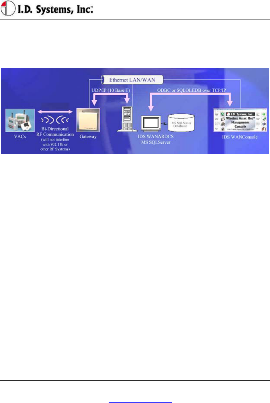
infrastructure of Gateways™, to I.D. Systems software (refer to the system diagram in Figure 1).
Figure 1: IDS Fleet Management System Diagram
The VAC device both sends and receives information, such as access control updates, pages, updated
configuration settings, and scheduled maintenance event information, and interacts with the vehicle’s
driver using a keypad, display, and optional ID readers.

Installation
I.D. Systems, Inc. One University Plaza, Hackensack, NJ 07601 000-0144-01
Tel: 201-996-9000; Fax 201-996-9144; email: support@id-systems.com Page 9 of 41
Installation
WARNINGS
* Please read this document in its entirety
BEFORE performing any installation. *
* Please disconnect main vehicle battery
BEFORE performing any installation. *
Standard Hardware for Installation
The standard components of the VAC system are installed on every vehicle type (Industrial Electric and
Internal Combustion). The following is a list of standard equipment that is required to install each VAC
system:
900-0144-02: Universal Vehicle Asset Communicator (VAC)
810-0113-0x: VAC-to-PCM Cable
835-0121-01 and -03: Mounting Hardware Assortments
825-0111-01: Vehicle Asset Communicator Mounting Bracket
During hardware installation and system configuration, a test sheet must be filled out and sent (via mail or
fax) to I.D. Systems, Inc. to certify that the installation was performed correctly. The test sheet is
provided with the hardware.
For technical support, contact I.D. Systems, Inc.:
By Phone: (201) 996-9000
By Fax: (201) 996-9144
By email: support@id-systems.com
Tools Required for Installation (Not Supplied)
In order to install the standard components of the VAC system, certain tools are required. The VAC is
mounted rigidly to each vehicle, thus requiring mounting hardware (supplied in Mounting Hardware
Assortment kits) and requiring holes to be drilled. In addition to mechanical mounting, some wiring and
electrical testing must be performed. Therefore, wire strippers and simple electrical test equipment are
required.
MOLEX RHT-1991 Ratchet tool or equivalent
VACUser’sGuide
I.D. Systems, Inc. One University Plaza, Hackensack, NJ 07601 000-0144-01
Tel: 201-996-9000; Fax 201-996-9144; email: support@id-systems.com Page 10 of 41
Minimum ¼” chuck drill
¼” drill bit
1 ¼” or 1 ½” hole saw
#10 socket and ratchet (or open-end wrench)
Medium sized slotted and Phillips screwdrivers
Wire stripper
Multimeter and test lead assortment
Note: The system is shipped with a set of hardware used to install the system on a vehicle (Mounting
Hardware Assortment kits). The hardware should accommodate most vehicle types. The hardware kit is
specified for high vibration industrial applications. I.D. Systems highly recommends using the MOLEX
RHT-1991 Ratchet tool (or equivalent) for crimping terminals. If using a different tool, I.D. Systems will
bear no responsibility for resulting installation failures.
System Connections Overview
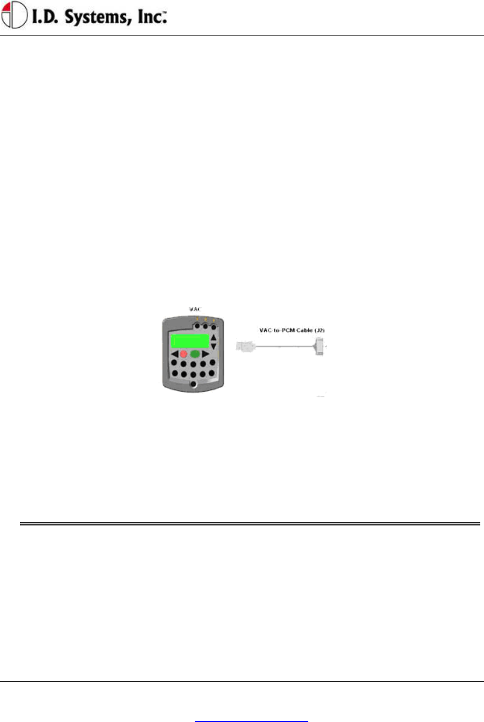
Figure 2: System Diagram
1. VAC: Vehicle Asset Communicator. User interface and intelligent industrial control device.
Operators read the display and use the keypad to interact with the vehicle control system. A two-
way radio transceiver is embedded within the VAC.
2. VAC-to-PCM Cable: Cable that connects the VAC to the vehicle’s Power and Control system.
This cable must route from the VAC mounting location (driver area) to the vehicle (typically the
engine/motor compartment).
Installation Summary
The installation must be performed in the order that follows:
Installing the VAC (with optional ID reader) [Items 1, 2]
Configuring the VAC using On-Screen Display
Before Starting the Installation
Before starting a VAC installation, make sure that all required tools and equipment and the Installation

Installation
I.D. Systems, Inc. One University Plaza, Hackensack, NJ 07601 000-0144-01
Tel: 201-996-9000; Fax 201-996-9144; email: support@id-systems.com Page 11 of 41
Verification test sheet are available. If not, do not proceed with installation. If all equipment is
available, record the following on the installation sheet:
The VAC serial number
Installing the VAC (and optional ID Reader)
The VAC contains the driver’s user interface to the system and also contains the embedded fleet
management software and RF capability. The VAC, therefore, must be mounted in a location that is
convenient for operator access (to the keypad, LCD and optional ID reader) and that is optimized for RF
performance. The VAC is wired into the vehicle. Therefore, selecting the proper location and verifying
correct installation is important to ensure correct functionality.
Selecting the VAC Mounting Location
Notes:
The VAC is mounted to the vehicle using the supplied VAC Mounting Bracket (modifications or
custom brackets must be approved by I. D. Systems in order to ensure proper functionality).
Procedure:
Select a location on the dash area of the vehicle to mount the VAC.
o The operator of the vehicle should be able to view the VAC’s display and access the
keypad and optional ID reader while sitting in the vehicle.
o The VAC should not obscure the operator’s line of sight or accessibility to the vehicle.
o The VAC display should not be obscured.
o The VAC’s antenna should be as far away from the vehicle’s chassis as possible (having
the antenna close to the metal of the vehicle [less than 3”] attenuates the unit’s RF
communications).
o The VAC should be securely affixed to the vehicle and is not adjustable for different
operator heights.
Select the location on the vehicle to which the bracket should be bolted or welded.
Mounting the VAC
If mounting with bolts, use the bracket as a template to drill holes in the vehicle for mounting the
VAC bracket. The bracket has to be secured to the vehicle by at least two bolts. Make sure that
nothing can be damaged on the vehicle while drilling or welding.
If the VAC-to-PCM cable has to run through the dash of the vehicle, drill using a 1¼” hole saw.
Assemble the VAC onto the Bracket.
If the VAC-to-PCM cable runs through the vehicle’s dash, insert a Grommet (supplied) in the
hole to prevent the cable from being damaged.

VACUser’sGuide
I.D. Systems, Inc. One University Plaza, Hackensack, NJ 07601 000-0144-01
Tel: 201-996-9000; Fax 201-996-9144; email: support@id-systems.com Page 12 of 41
Using the attached hex key tighten the hex nuts to secure the swivel points. The bracket is not
supposed to be adjustable. Failure of tightening the hex nuts will result in assembly failure.
Attach the 9-pin circular connector of the VAC-to-PCM cable (Item 4) to the circular connector
on the back of the VAC.
Route the VAC-to-PCM cable through the hole in the VAC mounting bracket and route all the
way to the vehicle interface location.
o Use the vehicle’s pre-existing cable-routing channels (where other cables are also run
throughout the vehicle) to prevent the cable from being damaged during vehicle use or
maintenance.
Installing VAC-TO-PCM Harness
The VAC-TO-PCM Harness connects the VAC to the vehicle. Through the harness, the VAC system
will get power from the vehicle, and have the ability to receive commands from the vehicle via the I.D.
Systems Serial Data Interface (IDSY SDI) protocol. Installation of this cable must be performed
according to the instructions below for the VAC system to operate properly.
Vehicle Cable Harness
Cable Pin-Out:
Pin Color Signal Name Comments
1 RED POWER Power (+)- TO REGULATED 6.5 VDC
2 BLACK POWERRTN Power return (-) - TO 6.5 VDC RETURN
3 WHITE ISEN(-) IDSY SDI SIMO (OPTIONAL)
4 GREEN RELAYIN IDSY SDI SOMI (OPTIONAL)
5 ORANGE RELAYOUT IDSY SDI SCLK (OPTIONAL)
6 BLUE VSEN1(-) IDSY SDI INT_NCS (OPTIONAL)
7 WHITE/
BLACK
VSEN1(+) IDSY SDI INTRPT (OPTIONAL)
8 RED/
BLACK
VSEN2(+) IDSY SDI WAKEUP (OPTIONAL)
9 RED/
BLACK
N/C NO CONNECT
Selecting the System’s Power and Ground Connections
Notes:

Installation
I.D. Systems, Inc. One University Plaza, Hackensack, NJ 07601 000-0144-01
Tel: 201-996-9000; Fax 201-996-9144; email: support@id-systems.com Page 13 of 41
The system requires an uninterrupted, regulated 6.5 VDC supply from the vehicle. The
supply should be continuous regardless of the condition of the vehicle. The only time the supply
is discontinued is when the vehicle’s battery is unplugged.
The interface should be the cleanest possible power source, free from noise and damaging voltage
spikes.
The current draw of the system in normal mode at 6.5 VDC is approximately 0.25 Amperes
Finishing the Installation
System Configuration
In order to complete the installation of the VAC system on a vehicle and to ensure proper operation of
the system.

VACUser’sGuide
I.D. Systems, Inc. One University Plaza, Hackensack, NJ 07601 000-0144-01
Tel: 201-996-9000; Fax 201-996-9144; email: support@id-systems.com Page 14 of 41
Standard VAC Operation
VAC Overview
The VAC device is the vehicle component of a comprehensive fleet management system provided by I.D.
Systems. The VAC incorporates a highly customized computer application, a two-way wireless
communications port, and a vehicle power and data interface. The complete fleet management solution
also requires other system elements: wireless infrastructure devices, termed Gateways, a server computer
running the ARDCS software, and at least one computer running WAN Console software. Combined,
the IDS Fleet Management solution provides the following major benefits:
Automated compliance with OSHA rules
Electronic, paperless OSHA checklists
Automated vehicle utilization analysis
Operator accountability
Real-time vehicle location tracking
Enhanced maintenance efficiencies
Significant cost savings
To achieve the above benefits, the VAC is designed to implement several critical Fleet Management
functions, including:
Driver OSHA checklist interface – allowing drivers to identify and communicate vehicle status by
answering vehicle-specific safety questions
Two-way paging – option that allows drivers to receive and respond to messages sent from plant
computers
Vehicle Utilization Monitoring – If the vehicle interface permits, provides accurate fleet
information through motion sensing, lift sensing, log-on time, and battery monitoring
Maintenance Management - predictive forecasting and driver notification of scheduled
maintenance
Access Control – tracks the current operator using the equipment. If the vehicle interface
permits, also prevents unauthorized operators from driving vehicles, using individual driver IDs
instead of vehicle keys
As a radio frequency (RF) and computing device, the VAC utilizes the most robust communication
protocol in the industry to ensure that all relevant data is communicated with the rest of the system.

Installation
I.D. Systems, Inc. One University Plaza, Hackensack, NJ 07601 000-0144-01
Tel: 201-996-9000; Fax 201-996-9144; email: support@id-systems.com Page 15 of 41
When in range of IDS Gateways, the VAC will:
Display an ‘in-range’ indicator, letting the driver know that information can currently be
communicated
Send any stored data, verifying receipt through a robust confirmation process
Synchronize with the most up-to-date access control information (add, delete or modify
authorized driver information)
Receive any updates to vehicle settings, such as battery and impact thresholds, or OSHA
questions
Update the vehicle’s location, and, if necessary, send a location update to the system
General Operation
Three different groups of operators will interact with the VAC – the standard driver, the Master User
driver, and the maintenance/installation user.
The standard driver will perform certain basic functions with the VAC (for Standard Driver Instructions,
see Basic Operation: LCD, Keypad, ID Reader on page 16). These features are:
Logging onto the vehicle to gain access
o Identifying himself/herself using an ID (either by typing the ID or through an ID device)
o Verifying his/her identity using a PIN (if required)
Logging off of the vehicle prior to leaving the vehicle unattended
Answering OSHA-required safety questions
Reading, responding to, and deleting pages (optional)
Identifying low vehicle battery condition
The Master User driver can perform the same basic functions with the VAC (For Master User
Instructions, see Granting Temporary Access (Master Users) on page on page 33), as well as:
Logging onto all vehicles
Granting temporary access to a currently unauthorized standard driver
The Maintenance/Installation User can perform the same functions as a Master User driver as well as
VAC configuration (For Maintenance Instructions, see Error! Reference source not found. on page
Error! Bookmark not defined.). The additional features include:
Assigning the Vehicle ID to the VAC
Enabling and disabling access control
Configuring the VAC sensors for motion sensing, lift sensing, and battery sensing
VACUser’sGuide
I.D. Systems, Inc. One University Plaza, Hackensack, NJ 07601 000-0144-01
Tel: 201-996-9000; Fax 201-996-9144; email: support@id-systems.com Page 16 of 41
Verifying impact sensing
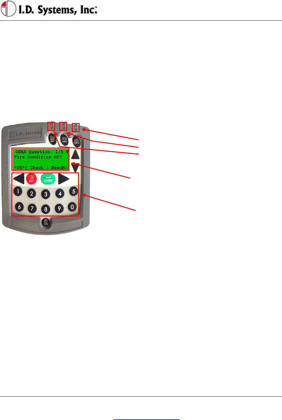
Basic Operation: LCD, Keypad, ID Reader and LEDs
The VAC incorporates a robust 20-key keypad and a 20-by-4 character display that is backlit for 15
seconds when a key is pressed. In addition, certain units are equipped with identification device readers
(proximity card, magnetic card, 1-wire memory chip such as an iButton, or smart card). The operator
interacts with the VAC using these devices in the following way:
VAC Display and Keypad Basics
LEDs:
• OSHA not filled
• Incoming, unread page
• Access Enabled
LCD Display: (Backlit, 20-by-4 characters)
Screen Contents: To interact with the driver, the VAC uses
a backlit display. The same display is used in Menu
Selection Mode, Digit Entry Mode and Pager Mode.
Keypad: (20-Key, Rugged with Tactile Keys)
20-Key Keypad: The keypad allows the driver to make
menu selections (in Menu Selection Mode), type digits (in
Digit Entry Mode) and review and respond to pages (in
Pager Mode).
ID Reader
VACs may be equipped with ID Readers for the quick and secure entry of driver ID numbers. ID
readers are mounted in the VAC. The ID reader is used:
During the Access Control log-in process (to quickly enter the driver ID)
During the Access Control log-off process (to quickly log off the current driver)
During the Grant Temporary Access process (to enter the ID of the temporarily-authorized
driver)
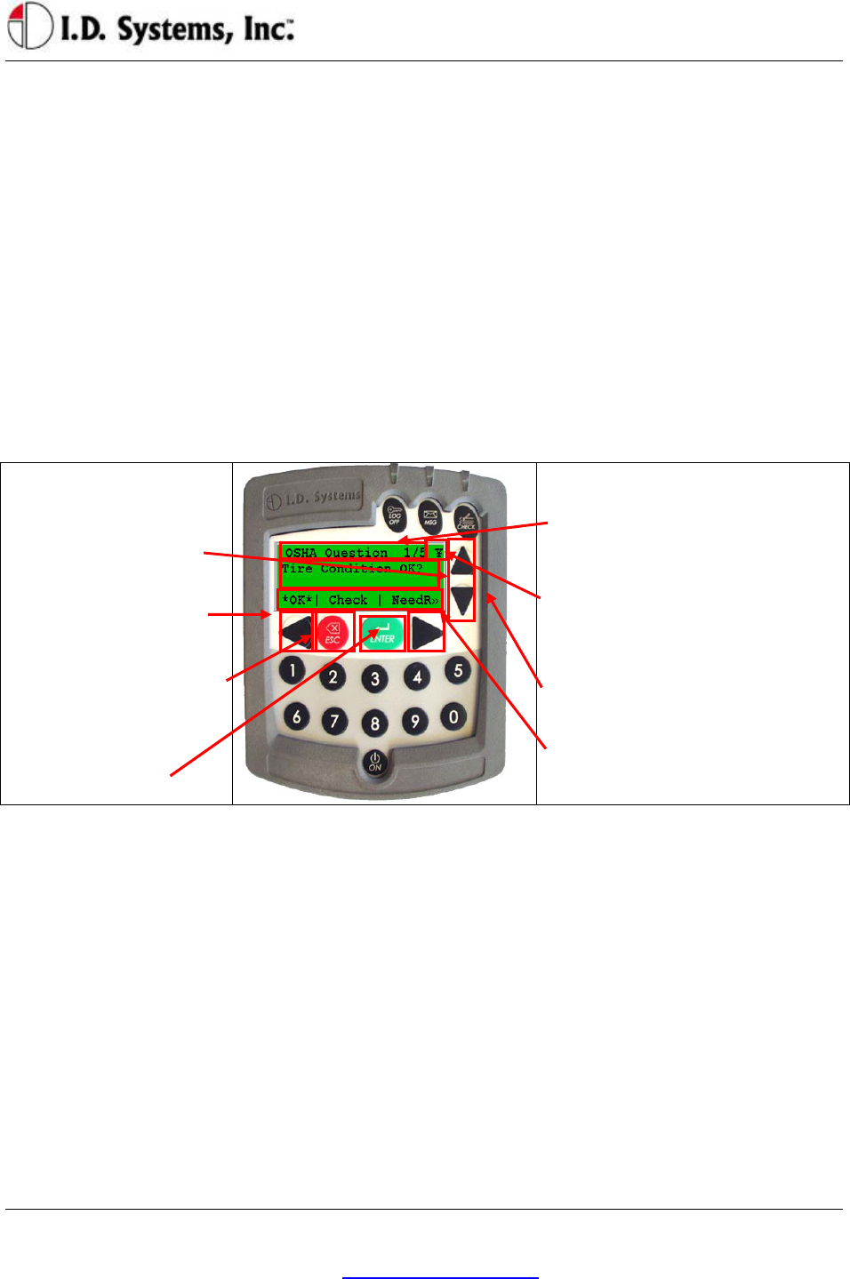
Menu Selection Mode
Most screens on the VAC involve reading displayed text and selecting from menu options. These screens
contain four major components:
Screen Title: The top line of the display. Indicates the title or subject of the current screen.
¥ (Yen): This symbol is the in-range indicator for the VAC. The faster it blinks, the closer the
Installation
I.D. Systems, Inc. One University Plaza, Hackensack, NJ 07601 000-0144-01
Tel: 201-996-9000; Fax 201-996-9144; email: support@id-systems.com Page 17 of 41
VAC is to a Gateway. When in range of a Gateway, a VAC will download any required data and
will attempt to upload data. The VAC will continue to function and record data, however, when
not in range of a Gateway.
Screen Data: The second and third lines contain screen data. If there are more than two lines of
screen data, the up and down arrows (keys 2 and 7) must be pressed to scroll through the data.
Menu Options: The bottom line of screen. Available menu options are listed, separated by ⎢
characters.
o Asterisked *selection* shows response that will be selected by pressing ENTER key
o Change *selection* by pressing right arrow or left arrow keys
o >> indicates more responses available by scrolling with right arrow key
o << (not shown) indicates more responses available by scrolling with left arrow key
o After highlighting *selection*, press ENTER key to confirm selection and proceed
automatically to the next screen.
Keypad: (20-Key, Rugged
with Tactile Keys)
Up-arrow and down arrow
scroll through screen data.
Left-arrow and right arrow
scroll through menu options
ESC: Return to previous
screen
ENTER: Confirm the
currently highlighted
selection.
LCD Display: (Backlit, 20-by-4
characters)
Screen Title: First line indicates title or
subject of current screen
¥ –‘Yen:’ In-range indicator. The faster
this blinks, the better the receipt of data
from Gateways.
Screen Data: Second and third lines
contain screen data.
Menu Options: Appear along the bottom
line of screen, separated by ⎢ characters
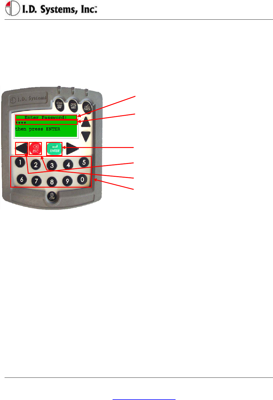
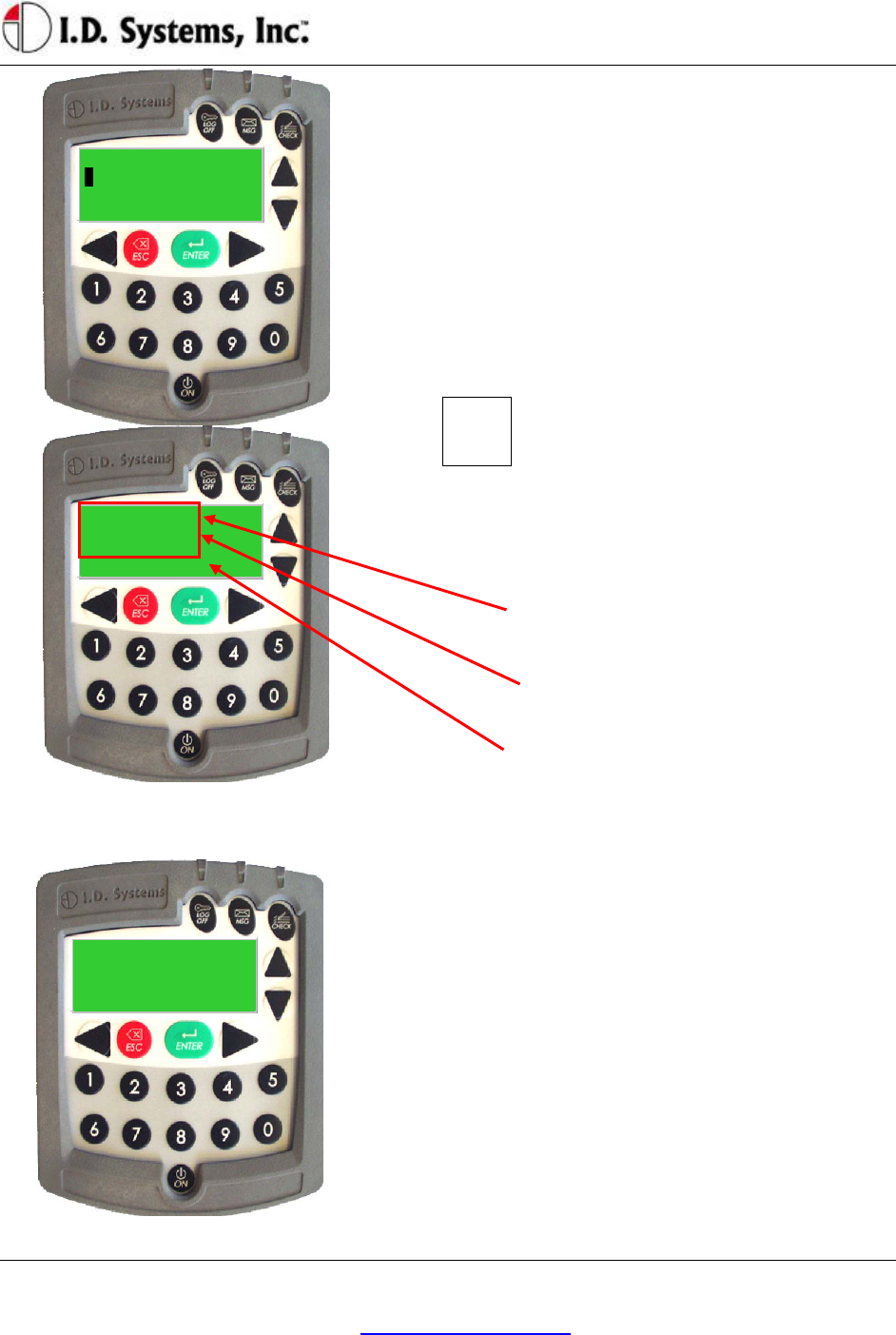
Digit Entry Mode
For VAC screens, which ask for a numerical entry, the digit entry mode screen will appear. These screens
contain two major components:
Screen Title: The top line of the display. Indicates the title or subject of the current screen.
Numerical Data: The second line contains the numerical data. A default value will appear of the
correct data length when entering this screen.
o A blinking cursor shows the current cursor location for data entry.
o Enter digits by typing desired number, 0-9 using the keypad
o Backspace using the Left Arrow key.
o Pressing ESC key will return to the previous screen.
o Press ENTER key to confirm numerical entry. The entry will consist of each digit
VACUser’sGuide
I.D. Systems, Inc. One University Plaza, Hackensack, NJ 07601 000-0144-01
Tel: 201-996-9000; Fax 201-996-9144; email: support@id-systems.com Page 18 of 41
displayed on the screen (typed as well as default digits, EXACTLY AS THEY APPEAR
ON THE SCREEN. For example, if ‘0000’ appears on the screen, and the user presses 2
then 1, the screen will read ‘2100’. In this case, 2100 will be submitted if the ENTER key
is pressed.).
o Therefore, to keep the default entry without making a change, simply press ENTER
without pressing any digits.
o
– LCD Display: (Backlit, 20-by-4 characters)
Screen Title: First line indicates title or subject of current
screen
Numerical Data: Second line contains numerical data
(Note: Password screen uses asterisks (*) to hide entered
data). Third line may contain helpful information.
Keypad: (20-Key, Rugged with Tactile Keys)
ENTER: Press this key to confirm the current entry
Left Arrow: Press this key to back up one space
ESC:Press this key to return to previous screen
0-9: Press these keys to enter a digit at the current cursor
location
Access Control (All Users): Logging on and off the Vehicle
Access Control Overview
One feature of the VAC is to prevent unauthorized access to the VAC, and, optionally, the vehicle. Each
VAC is assigned a vehicle number (often similar to the number marked on the side of the vehicle), and
that number has an associated authorization list that contains valid drivers and, for each driver, the times
of day and days of week for which they are allowed drive that particular vehicle. The VAC stores the
authorization list and is updated, if changes have been made, when in radio range of any Gateway.
In order for vehicle access control to prevent vehicle access, it is required that the vehicle comply with the
I.D. Systems Serial Data Interface protocol. For a compliant vehicle, unless the VAC is in ‘bypass mode,’
all Standard, Master User and Maintenance drivers must log into the VAC to gain access to the vehicle.
Once authorized, the driver may also be required to use a key to start or drive vehicle.
Whether or not access is controlled by the VAC, once logged onto (or ‘assigned to’) a VAC, the driver is
Installation
I.D. Systems, Inc. One University Plaza, Hackensack, NJ 07601 000-0144-01
Tel: 201-996-9000; Fax 201-996-9144; email: support@id-systems.com Page 19 of 41
responsible for the vehicle. Therefore, it is imperative that drivers do not leave assigned vehicles
unattended. If, however, a driver forgets to log off, the VAC is configured to ‘time out’ after a
configurable period of non-use. (system-wide default: twenty minutes, changed via the ARDCS –
Beacon). While this idle-timeout feature is a fail-safe, it will not prevent another driver from taking an
assigned vehicle during the time prior to the time-out. In addition, the idle-timeout feature may be
disabled for the entire system (via ARDCS Beacon) or set on a vehicle a vehicle-by-vehicle basis (via
System Admin Tool – Modify Vehicle – Advanced Settings).
Drivers identify themselves to the VAC for access to a vehicle using their Access ID number. To enter
that number, the driver either uses the keypad or an ID device (such as a proximity card, smart card,
magnetic card, or iButton). The ID method is usually chosen to match that which the driver already uses
for other access control purposes (such as doorway entry). The Access ID number may not be the same
as the employee ID number, depending on the methodology used at the facility. The Access ID numbers
are linked to the drivers using the Console’s System Admin Tool.
Driver IDs are associated with VAC IDs using groups. Authorization groups are created using the
Console’s System Admin Tool. Both vehicles and drivers are added to groups. When a driver belongs to
the same group as a vehicle, and if that group is granted an authorization for the current time of day/day
of week, then the driver may gain access to the vehicle. All driver, group and authorization time
information is configured with the System Admin Tool and stored on each VAC. Initial configuration
and ongoing updates occur wirelessly and automatically, when VACs are in range of Gateways.
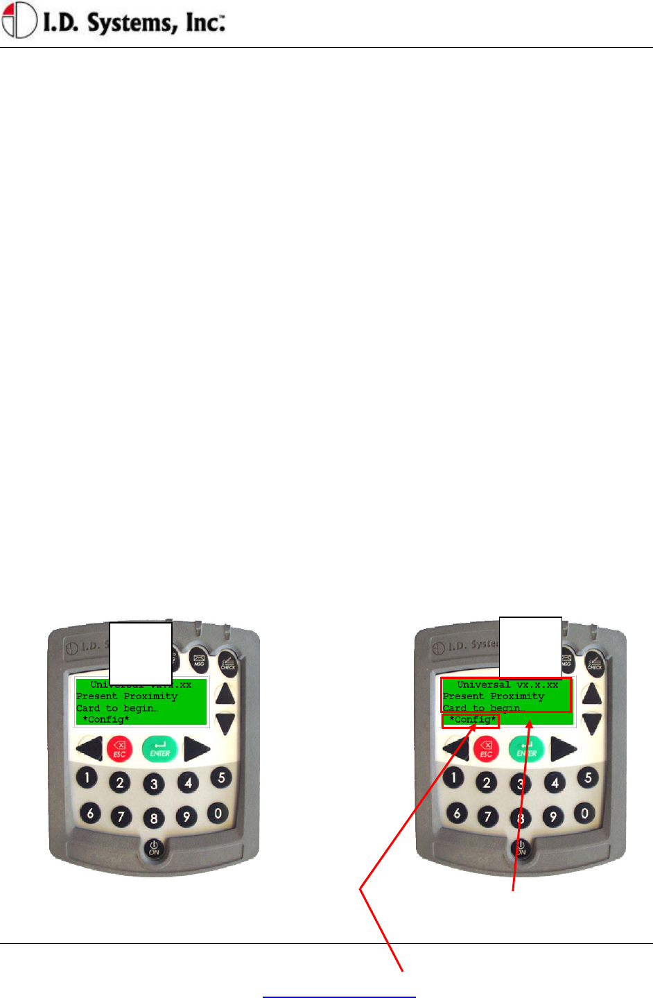
Logging onto the VAC
If VAC screen is blank (only on certain internal
combustion vehicles), turn vehicle ignition key on. Follow instructions on how to enter driver’s ID
(either by typing driver ID or presenting an ID
card – proximity, magnetic stripe, smart-card or
1 2
VACUser’sGuide
I.D. Systems, Inc. One University Plaza, Hackensack, NJ 07601 000-0144-01
Tel: 201-996-9000; Fax 201-996-9144; email: support@id-systems.com Page 20 of 41
iButton)
*Config*: (if applicable) Allows a Maintenance
User to log in without an ID card; for keypad-
only systems, this menu option does not appear.
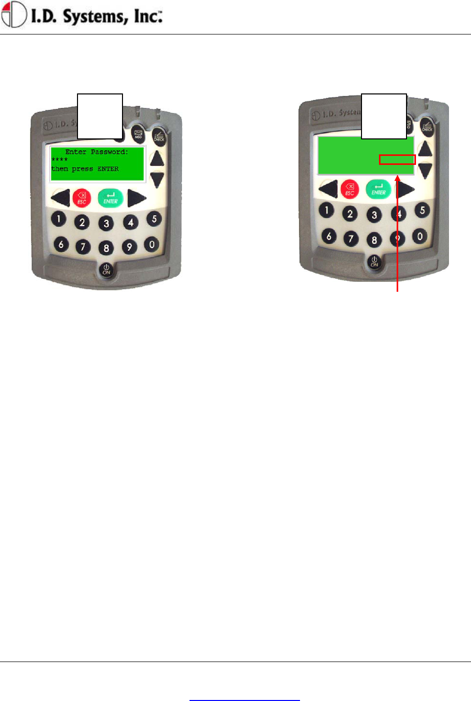
A PIN code will then be requested (if the system is
configured to have PIN). Use the numeric keys to
enter PIN. After entering PIN (hidden by ****
characters for security), press ENTER key. If no PIN
is required, press ENTER when prompted with default
PIN of 0000.
If driver ID and PIN are authorized, vehicle
start-up will be enabled and driver can use
vehicle. VAC screen will prompt driver to
complete OSHA vehicle inspection checklist. If
driver is not authorized, see Denial of Login on
page 21.
3 4
Installation
I.D. Systems, Inc. One University Plaza, Hackensack, NJ 07601 000-0144-01
Tel: 201-996-9000; Fax 201-996-9144; email: support@id-systems.com Page 21 of 41
Driver Type(optional)
The type of driver access is displayed on the top line once
authorized, indicating, for example, whether the current
user is a standard, authorized user (shown), a master user,
an administrative user, etc. The displayed options are:
• Authorized User: Standard user
• Master User
• Temp User: User assigned temporarily by a Master
User
• MAINT User: Logged in using system-configured
maintenance ID and PIN
• ADMIN User: Logged in using system-configured
maintenance ID and PIN
• MAINT (H) User: Logged in using default
maintenance ID and PIN (only available on new
VACs prior to first database synchronization)
• ADMIN (H) User: Logged in using default
administrative ID and PIN (only available on new
VACs prior to first database synchronization)
• All Users: System is in bypass mode, allowing any ID
to start the vehicle (Security LED will be flashing)
• All Trained: System is in bypass mode, allowing any
valid driver ID to start the vehicle (Security LED will
be flashing)
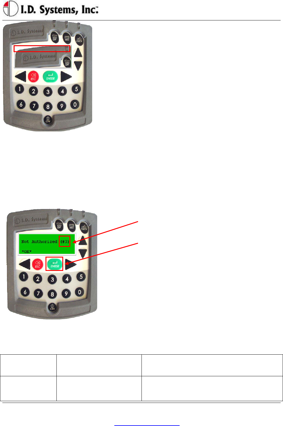
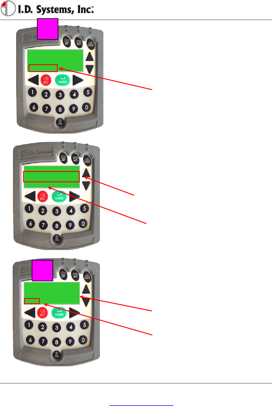
Denial of Login
Login Denial Screen
Violation Code: Number in parenthesis indicates the
reason for denial. See explanations in table below.
In all cases, operator should press the ENTER key to
restart the login process.
Violation Code Reason for Login Denial Explanation
1 Not currently authorized.
Driver is not authorized for that time period on
that vehicle (set using Console’s System
Admin Tool), but would otherwise be

VACUser’sGuide
I.D. Systems, Inc. One University Plaza, Hackensack, NJ 07601 000-0144-01
Tel: 201-996-9000; Fax 201-996-9144; email: support@id-systems.com Page 22 of 41
Violation Code Reason for Login Denial Explanation
authorized.
A Master User can add this driver using the
Temporary Access feature (see Granting
Temporary Access (Master Users) on page 33)
2 Not authorized on this day.
Driver is not authorized for that day on that
vehicle (set using Console’s System Admin
Tool), but would otherwise be authorized.
A Master User can add this driver using the
Temporary Access feature (see Granting
Temporary Access (Master Users) on page 33)
3 Not authorized on vehicle.
Driver is not authorized for that particular
vehicle (set using Console’s System Admin
Tool), but he/she is authorized for other
vehicles.
A Master User can add this driver using the
Temporary Access feature (see Granting
Temporary Access (Master Users) on page 33)
4 Invalid password.
PIN code does not match driver ID (set using
Console’s System Admin Tool).
5 Invalid driver ID.
Driver is not registered in the authorized access
control database (set using Console’s System
Admin Tool), or driver’s medical, training or
certification date has expired (set using
Console’s System Admin Tool).
A Master User CAN NOT add this driver using
the Temporary Access feature (see Granting
Temporary Access (Master Users) on page 33)
6 Wrong login method.
Operator tries to enter ID by keypad on a VAC
configured with an ID reader.
7 Critical OSHA Interlock
(Optional)
The Vehicle has been disabled for regular users
because a “Critical” safety item response was
selected.
8 Embedded Users Disabled
(Optional)
The embedded logins used to configure VACs
prior to synchronization will be disabled once
the vehicle completes its first synchronization.
This error appears when attempting to
manually type in an embedded login id.
9 Vehicle is out of service or
has no valid authorizations
The vehicle has been taken out of service via
the WAN Console or does not belong to a
group with a valid authorization.
NOTE: Repeated failure to log into the VAC will trigger an alert on the ARDCS which can
Installation
I.D. Systems, Inc. One University Plaza, Hackensack, NJ 07601 000-0144-01
Tel: 201-996-9000; Fax 201-996-9144; email: support@id-systems.com Page 23 of 41
Authorized User:
Universal vx.x.xy
Present Proximity
Card to begin...
*Config*
be emailed or sent by pager to specified personnel (See ARDCS User’s Guide).
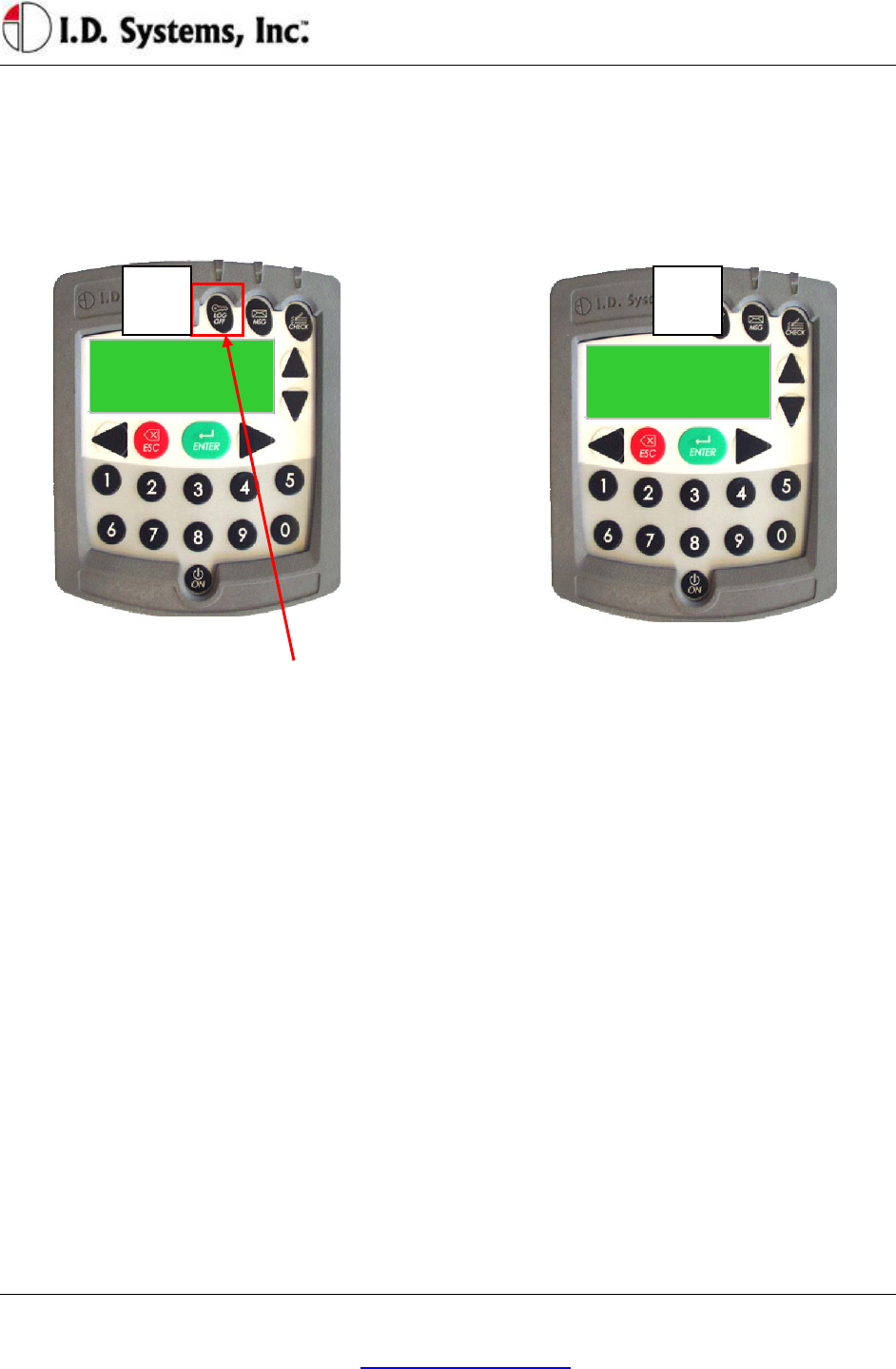
Logging Off of the VAC
WARNING: When an operator leaves a vehicle, the operator is still responsible for that vehicle until
he/she logs off (or until the authorization times out) – See Access Control Overview above.
To log off of the vehicle, first come to a stop.
While not in motion, press the “LOGOFF”
button. Logging off will be prevented if in
motion.
You can also logoff by presenting an ID device
to the ID Reader. The ID device does not need
to belong to the current driver to log off the
current driver.
When the driver successfully logs off the vehicle,
the Main Screen will appear.
Electronic OSHA Safety Checklists (All Users)
An important safety and maintenance-related feature of the VAC is to provide on-screen, on-vehicle
electronic vehicle inspection checklists. As required by the OSHA, vehicle-specific questions must be
answered by each vehicle driver, once per shift, for each vehicle he/she drives. The VAC provides a
simple-to-use, convenient, automated way of answering these questions.
Once an authorized driver logs onto a VAC, the VAC becomes operational. The driver is then prompted
to answer OSHA questions via a blinking indicator (on the LCD screen and via the LED on the attached
Proximity Card Reader). The driver must enter the OSHA Question mode and answer each question in
order for the OSHA requirement to be fulfilled. Once completed, subsequent logons during the shift, on
the same vehicle by the same driver, will not prompt for OSHA checklist completion. If another driver
uses the same vehicle during the same shift, he/she will be required to answer OSHA questions. Similarly,
if the same driver uses a different vehicle during the same shift, he/she will be required to answer OSHA
2

VACUser’sGuide
I.D. Systems, Inc. One University Plaza, Hackensack, NJ 07601 000-0144-01
Tel: 201-996-9000; Fax 201-996-9144; email: support@id-systems.com Page 24 of 41
questions. The duration of the shift is configurable (default: 14 hours; configurable only prior to receipt
of VAC units).
The OSHA question screen mode lists customizable questions, specific to the vehicle on which the VAC
is installed. The driver is expected to answer each question after performing the required inspection task.
The questions and responses can be changed wirelessly at any time by using the Console’s OSHA
Checklist Tool. The questions can be tailored to the specific vehicle or vehicle type, while each response
can be configured as Normal, Warning or Critical (see Console’s System Admin Tool).
The VAC stores responses to OSHA questions and communicates them when in radio range of any
Gateway. Warning and Critical responses can be sent, via email or page, directly to maintenance by the
ARDCS (See ARDCS User’s Guide). This real-time notification allows drives to identify and transmit
vehicle safety issues directly to maintenance employees without driving the vehicle to the maintenance
area. This leads to more proactive response to vehicle issues, resulting in a safer fleet of vehicles. In
addition, when the vehicle is brought in for preventative maintenance, a report can be run using the
Console’s Report Tool which lists all outstanding driver-identified safety issues so that a complete vehicle
repair can be performed.
Optionally, Critical responses can trigger a safety-initiated log-off, termed Critical OSHA Interlock. In
this mode, the VAC will prevent log-in to all normal, authorized operators (excluding Master and
Maintenance users) until an authorized supervisor reactivates the vehicle using the WAN Console. This
feature is incorporated to prevent vehicle use after a potentially dangerous condition has been identified.
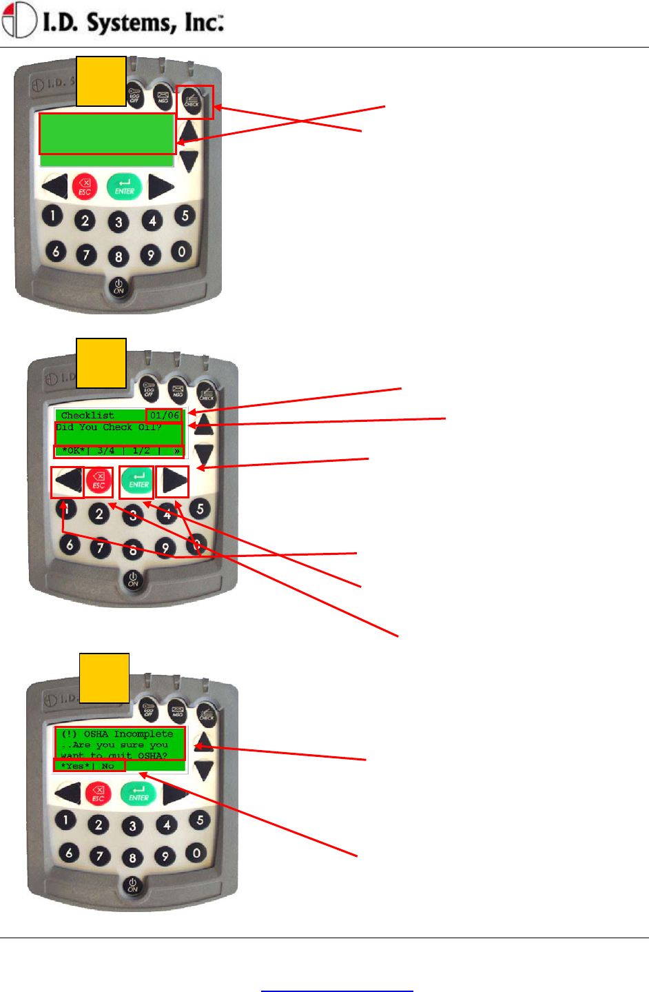
OSHA Question Mode
OSHA checklist questions can be answered at any time after logging on to a vehicle. If a new
maintenance item occurs after a driver has already completed his/her responses, the driver can still re-
enter OSHA responses, which will log and alert maintenance of the previously unidentified issue.
Installation
I.D. Systems, Inc. One University Plaza, Hackensack, NJ 07601 000-0144-01
Tel: 201-996-9000; Fax 201-996-9144; email: support@id-systems.com Page 25 of 41
Authorized User:
>OSHA<
After a successful login, the VAC screen will show
this message. If OSHA questions have not been
completed, >OSHA< will continually flash.
The operator should simply press the “CHECK”
button.
The first checklist question will then appear, with
multiple-choice responses.
Note: some vehicles are also configured with an
LED that will flash to remind operators and nearby
personnel that the checklist is unfilled.
OSHA vehicle checklist screens:
Question # / of total # of questions.
Text of question.
Available responses along bottom line of screen,
separated by ⎢ characters
(>> indicates more responses available by scrolling
with right arrow key).
Asterisked *selection* shows selected response.
Press right or left arrow keys to change *selection*
Press ENTER key to confirm current selection and
proceed to the next question.
Press ESC to go back one question.
When the last question has been answered, the
checklist has been completed successfully, and the
screen will indicate: - OSHA complete! –
If operator tries to exit checklist before it is
complete (by pressing the ESC key), the screen
will show this message. Exiting prior to
completion will not fulfill the OSHA requirement
and responses will be lost.
To exit the checklist, operator chooses *Yes* by
pressing ENTER.
To resume working on the checklist, press the right
arrow key to select *No* and then press ENTER.
3
2
1

VACUser’sGuide
I.D. Systems, Inc. One University Plaza, Hackensack, NJ 07601 000-0144-01
Tel: 201-996-9000; Fax 201-996-9144; email: support@id-systems.com Page 26 of 41
Critical OSHA Shutdown (Optional)
When a user replies with a critical response to an OSHA question, and upon the completion of the entire
checklist, the user is logged off immediately and the VAC remains disabled for standard users. Only
Master and Maintenance users will be able to log on until the vehicle is reactivated from the WAN
Console by an authorized person. As a result of this feature, users are required to complete their safety
checklists in a safe location, in case of a VAC deactivation.
Two-Way Text Paging (All Users)
A useful feature of the VAC is two-way text messaging (‘Pager’). Using the Console’s Paging Tool (See
Console User’s Guide), software users can send messages from their computer to operators or vehicles.
The messages will be stored in the VAC’s Pager Inbox (up to ten) for review by the driver. Messages sent
from the Paging Tool can be directed to drivers in several ways, including:
Vehicle Pages: The destination is a particular vehicle, identified by vehicle number. The page will
be in the Inbox of any driver operating the vehicle until it is deleted or expires.
Driver Pages: The destination is a particular driver; therefore, the page will be in the Inbox of the
VAC that the driver is assigned to, until the page is deleted or expires. If the driver logs off of a
vehicle with a Driver page without deleting it and before expiration, the page will ‘follow’ the
driver to the next vehicle he/she logs on to.
Group Pages: The destination is a group vehicles or drivers, identified by vehicle or driver group
(See the explanation of groups in Access Control Overview on page 18). The page will be sent
out to all vehicles or drivers in the group and behave the same as a Vehicle or Driver page,
respectively.
Broadcast Pages: The page will appear in every vehicle’s Inbox, regardless of the driver operating
the vehicle until it is deleted or expires.
When there are pages in the Inbox, the driver can enter Pager mode to review the pages. Pager mode
allows a driver to scan the Inbox and selectively read or delete pages. The driver may enter Pager mode
only when their vehicle is idle for safety reasons.
Pages are transmitted from the database to the Gateway nearest the destination VAC. If the VAC moves
to a new Gateway area prior to receiving the page, the page will be transmitted to new Gateway. If the
VAC confirms receipt of the page and if there is room in its Inbox, the page will be stored on the VAC
and the page indicator will blink. The new page will be identified with an ‘unread’ indicator. If a page
expires before being stored on the intended VAC (indicated in the Console’s Paging Tool), the sender
must resend the page.
Installation
I.D. Systems, Inc. One University Plaza, Hackensack, NJ 07601 000-0144-01
Tel: 201-996-9000; Fax 201-996-9144; email: support@id-systems.com Page 27 of 41
Authorized User:
-Page-
After responding to pages, drivers may drive their vehicle near a Gateway (driver will see ¥ indicator on
VAC display) to ensure that their responses get back to the sender as soon as possible. Regardless, all
responses are stored on the VAC for upload as soon as the VAC can communicate with any Gateway.
All pages have standard options for reading, deleting and exiting the page text. Pages may or may not
have additional responses for the driver to select from. Regardless, all pages create acknowledgements
which are sent back to the sender when the VAC comes in range of a Gateway, including:
Received: The time that the VAC received the page.
Read: The time that a page was read by the driver.
Deleted: The time a page was deleted by the driver.
Expired: The time that the page expired without being read.
Any responses, and the times that the responses were input by the driver.
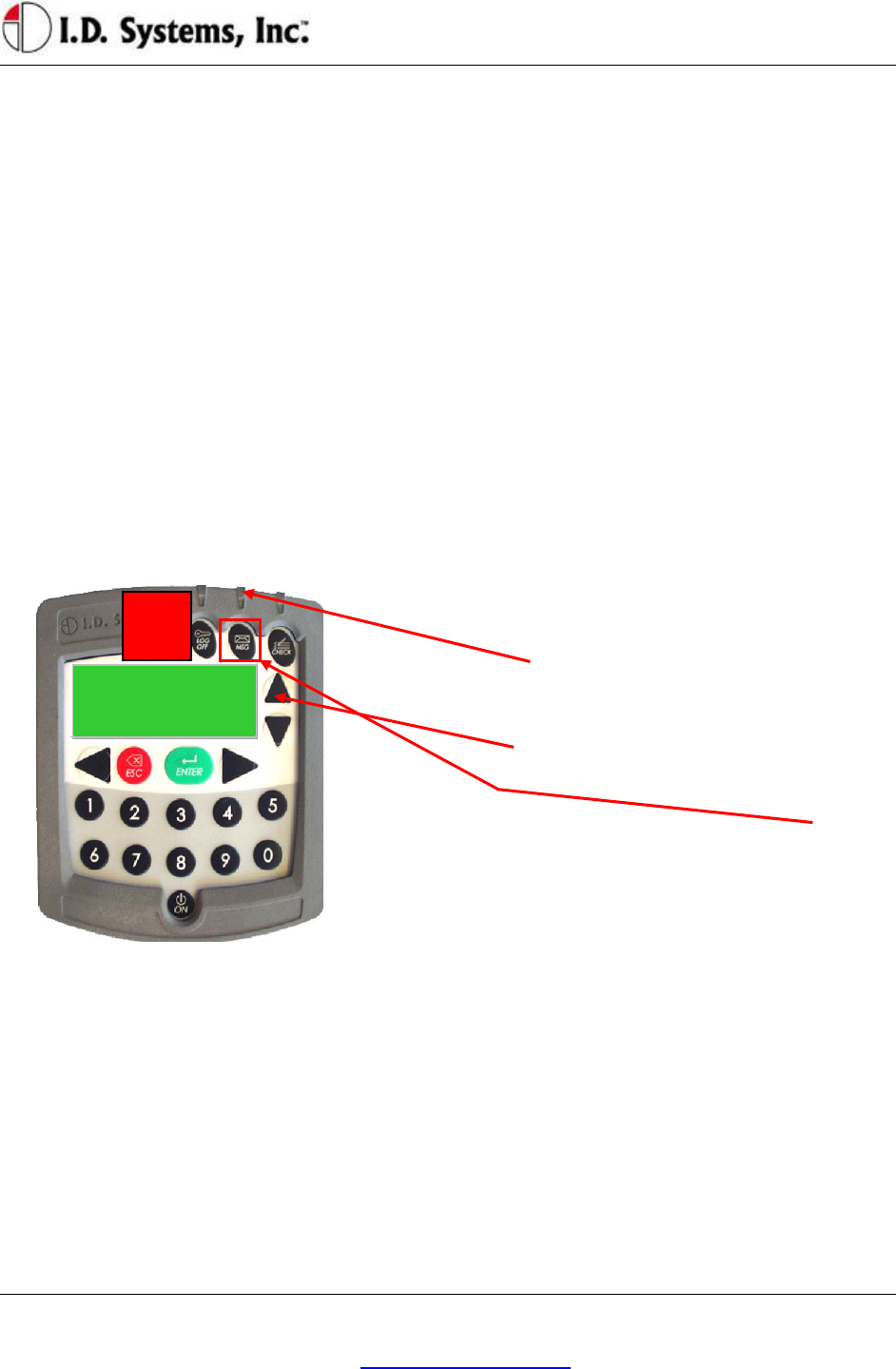
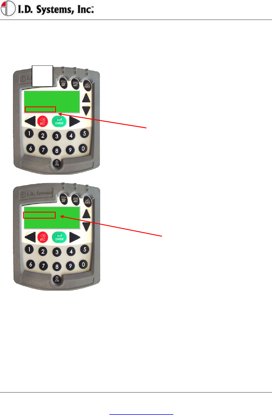
Viewing and Responding to Text Pages
MSG LED will blink in the event of a page.
On the main VAC screen, a flashing ‘– page –’
indicator (small letters) informs the operator that a
message has been received.
To view the message Inbox, press the MSG key.
1
VACUser’sGuide
I.D. Systems, Inc. One University Plaza, Hackensack, NJ 07601 000-0144-01
Tel: 201-996-9000; Fax 201-996-9144; email: support@id-systems.com Page 28 of 41
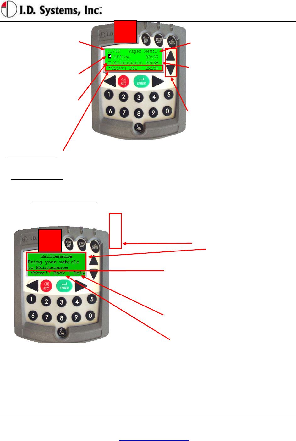
“XX /Y Y” shows sequence
# of message selected /
out of total # of messages
Flashing cursor indicates
which message is selected.
Message status indicators:
Old (read) message: “√”
New (unread) message: “□”
Pager screen: (Inbox)
“New: #” shows how many new, unread
messages have been received.
Each message summary line shows:
Status Indicator (“□” in this case, for
“unread”), Message Subject
(“Maintenance” in this case) and Time
Sent (24-hour format, “09:36” in this
case).
Note: only two message summary lines
fit on the screen at a time. To scroll
through the entire Inbox, use the Up and
Down arrow keys.
To Read a Message: Scroll up or down until flashing cursor is on desired message; make sure *View* is selected
(use right / left arrow keys if necessary to select); then press ENTER key. Message Detail screen will appear.
To Delete a Message: Scroll up or down until flashing cursor is on message to be deleted; make sure *Del* is
selected (using right/left arrow keys); then press ENTER key.
To Return to Main Screen: Select *Exit* using right/left arrow keys; then press ENTER key.
Message Detail screen:
Full Menu Text
If message does not all fit on screen, the *More*
menu option is automatically highlighted. Press
ENTER key to view the rest of the message.
At the bottom of the message, the *Top* option
appears. Press ENTER key to return to the
beginning of the message.
To Delete Message: Select *Del* by scrolling with
right/left arrow keys, then press ENTER key.
To Return to Pager screen: Select *Back* and
press ENTER ― or just press ESC key.
3
2

Installation
I.D. Systems, Inc. One University Plaza, Hackensack, NJ 07601 000-0144-01
Tel: 201-996-9000; Fax 201-996-9144; email: support@id-systems.com Page 29 of 41
If a message requires a response, the on-screen
menu will also display the multiple-choice
response options available (in addition to the
default options listed in step 3).
Select desired response *option* using right/left
arrow keys, then press the ENTER key to log and
transmit response.
Note: in some cases, a certain response (e.g.
“Accept”, in reply to a work order) will prompt
another level of response options (e.g. “Complete”,
to confirm the work ordered has been completed).
Also, some responses may automatically delete the
page, while others do not. The sender of the page
configures these settings.
Vehicle Utilization Monitoring (All Users)
One feature of the VAC is its monitoring of vehicle utilization. Vehicle monitoring requires that the
vehicle comply with the I.D. Systems Serial Data Interface protocol. For a compliant vehicle, a VAC will
record utilization data both when a driver is logged on and when the vehicle is unassigned. Vehicle
monitoring is invisible to the driver of the vehicle and requires no interaction for collection and
transmission of utilization data. The VAC will store utilization data in internal memory and transmit that
data to any IDS Gateway when in communication range. The data is then automatically downloaded and
stored in the IDS Database via the ARDCS software (see ARDCS - Data Listener).
Utilization information for a compliant vehicle includes the following:
Current Driver: The driver currently logged onto the vehicle
Motion: Received via the vehicle serial interface port, when the vehicle is in motion
Lift: Received via the vehicle serial interface port, and recorded when the lift motor is engaged
Engine On (Internal Combustion Only): Received via the vehicle serial interface port, and
recorded when the engine is on but the vehicle is in neutral.
Assigned Time: Recorded while a driver is logged onto the vehicle.
Location: Recorded while moving throughout a facility, when in range of IDS Gateways.
Utilization data is often used to create reports and graphs (see the Console's Report Tool) to analyze and
improve fleet utilization. In addition, the Console's Graphical Viewer provides a visual representation of
the current and historical location, status, and utilization of vehicles, and allows for filtering of vehicles to
identify and locate unassigned vehicles.
4

VACUser’sGuide
I.D. Systems, Inc. One University Plaza, Hackensack, NJ 07601 000-0144-01
Tel: 201-996-9000; Fax 201-996-9144; email: support@id-systems.com Page 30 of 41
Motion Safety Feature (Optional – Standard and Master Users)
A feature may be enabled in which the VAC’s display and keypad will become inoperative when the VAC
senses that the vehicle is in motion. This feature requires that the VAC is monitoring vehicle motion via
its serial data interface. It is used to prevent drivers from interacting with the VAC during vehicle
operation, a possible safety hazard. When logged in, Standard or Master users’ displays will become blank,
and a single, blinking cursor will appear on the display when the vehicle is in motion. Additionally, the
keypad will be inoperative. Upon stopping, the display will resume on the same screen as when it went
blank.
Note: Maintenance users can always see their display and use their keypad, permitting them to address
VAC installation or reconfiguration, even when motion-sensing is not properly configured.
Battery Rotation (Optional Module - All Users)
The Battery Rotation module optimizes vehicle battery life by maintaining the state of each battery in the
system and automatically suggesting replacements for discharged vehicle batteries. When a battery has
sufficiently discharged and should be replaced, the battery rotation module is used by the vehicle operator
to request a replacement for this battery.
With a prox-card assigned to each battery, the system can validate whether the operator followed the
recommendation or took an alternate (for example, if the recommended battery is damaged). After a
vehicle is powered down for more than 30 seconds (minimum for a valid battery swap), the VAC requires
the operator to present a valid battery prox-card when logging in. This prox-card should be attached to
the newly added battery. The VAC validates the prox-card and only accepts cards that represent actual
batteries.
Configuration of the module and corrections to battery assignments are made through the
WANConsole’s Battery Rotation Tool (see WANConsole User’s Guide). The system supports corrective
action through a graphical user interface, on any computer installed with the Console, for reassigning
batteries to chargers and vehicles, and for taking equipment out-of-service as needed.
The system expects that discharged batteries are placed on the same charger from which the new battery
is taken. Note that if the actual swap was not a ‘swap-in-place’, the charger number associated with the
discharged battery will be incorrect (though the charging area will still be correct). Note that if an operator
did not follow a recommendation, but performed a manual swap (e.g. by driving to the nearest charging
area and manually looking for an appropriate, charged battery), recommendations sent to other drivers for
Installation
I.D. Systems, Inc. One University Plaza, Hackensack, NJ 07601 000-0144-01
Tel: 201-996-9000; Fax 201-996-9144; email: support@id-systems.com Page 31 of 41
Authorized User:
*BattReq*
Authorized User:
Requesting..
*BattReq*
a short time period (default: five minutes) may contain incorrect charger data, unless corrective action is
taken through the WANConsole’s Battery Rotation Tool.
Battery Request:
Battery Request:
When >LOW BATT< blinks on the VAC screen,
the operator selects ‘BattReq’ to receive a battery
recommendation.
Battery Request Status:
A ‘Requesting..’ indicator blinks until
communication has been established with a nearby
Gateway
1
VACUser’sGuide
I.D. Systems, Inc. One University Plaza, Hackensack, NJ 07601 000-0144-01
Tel: 201-996-9000; Fax 201-996-9144; email: support@id-systems.com Page 32 of 41
1:Maint Shop
Chrg: 0003
Batt: 0017
*More*| Back | OK »
01/01 Pager New:1
Battery 17:59
*View*| Del | Exit »
Present Battery ID
To begin…
*Cancel*
Battery Recommendation:
Up to two battery recommendations will arrive in a
page. The Page indicator will blink. Select
*Pager* from the main driving screen and press
ENTER to view the Battery page.
Battery Recommendation - Detail:
To view each recommendation, scroll down (see
Two-Way Text Paging guide).
Charger Area name designates a nearby charger
location.
Chrg: the charger number for depositing the
discharged battery (currently on the vehicle)
Batt: the battery ID of the recommended battery.
Battery Validation:
Battery Validation:
After an operator presents his/her prox-card, the
operator is prompted to present a valid Battery
Prox-card.
Touch the prox-card or prox-fob attached to the
newly added battery to the VAC’s prox-reader to
proceed. (Note: Only valid battery prox ID’s
will be accepted)
If there is no prox-card or prox-fob on the new
battery, contact maintenance to proceed.
4

Installation
I.D. Systems, Inc. One University Plaza, Hackensack, NJ 07601 000-0144-01
Tel: 201-996-9000; Fax 201-996-9144; email: support@id-systems.com Page 33 of 41
Battery Request Troubleshooting:
If the ‘Requesting..’ indicator continues to blink for more than 10 seconds, operator should attempt to
move vehicle closer to a Gateway.
If operator is near a Gateway but the ‘Requesting..’ indicator blinks for more than 30 seconds, there is
most likely a problem with that Gateway. The operator should move to another Gateway or consider
proceeding with a manual swap. An administrator should be alerted to this condition.
If the ‘Requesting..’ indicator disappears, but no page arrives on the VAC for 30 seconds after the request
is submitted, the network is likely to be down, or the ARDCS is not running. The operator should
consider proceeding with a manual swap. An administrator should be alerted to this condition.
Security Module (Optional Module - All Users)
An optional module geared towards demands of high security installations analyzes individual vehicle use
and posts warnings on the ARDCS and on the vehicle when suspicious activities take place.
Using the high security module, system-wide “forbidden zones” can be set up using the Console (see
WANConsole User’s Guide) and also pre-programmed into the VAC. If any vehicle enters such a zone,
an alert will immediately be raised on the ARDCS (see ARDCS User’s Guide) and Graphical Viewer (see
WANConsole User’s Guide). In addition, an attached Security LED and on-screen text will indicate the
source of the security issue as follows:
Security Issue LED Blink Rate
(repeated)
LCD Text
Gateway Location Prohibited Area Fast Blink (Critical Issue) S-Zone
VAC Out of Range Slow Blink (Warning) O-Zone
Authorization is in Emergency Mode Slow Blink (Warning) Access
Granting Temporary Access (Master Users)
A Master User is granted access to all vehicles in the system. In addition, a Master User can assign access
for a period of 24 hours to a driver in the system that is not authorized for a particular piece of equipment.
For example, if a trained forklift driver from the Receiving department needs to use a Shipping vehicle, a
Master User can temporarily grant access on the Shipping vehicle to the trained driver. Note: The driver
must already be a valid driver in the system to receive temporary access; unrecognized ID numbers will
still not be valid. The duration of temporary access is configurable (default: 12 hours; configurable prior
to shipping VACs).
VACUser’sGuide
I.D. Systems, Inc. One University Plaza, Hackensack, NJ 07601 000-0144-01
Tel: 201-996-9000; Fax 201-996-9144; email: support@id-systems.com Page 34 of 41
Authorize Employee
Present Proximity
Card to authorize
*Cancel*
Authorize Employee
Authorized for:12hrs
*OK*
Authorized User:
Requesting..
*Add User*
On the main VAC screen, a Master User will have
an option to *Add User*.
To temporarily add an existing driver to a vehicle
to which they do not normally have access, scroll
to *Add User* using the right/left arrow keys, and
then press the ENTER key.
Add User screen:
Once in the Add User screen, a User ID can be
entered which will then be granted temporary
access to the vehicle. Then enter the User ID,
follow the prompt (requires typing the user ID for
keypad systems or using the driver’s ID device).
To return without adding a temporary user, scroll
to *Cancel*, and press the ENTER key.
Add User Confirmation screen:
Once the ID of the temporary driver is added, the
confirmation screen will indicate the duration of
temporary access.
When done, select *OK* and press the ENTER
key to return to Master User’s main VAC screen.
1
3
AppendixA
I.D. Systems, Inc. One University Plaza, Hackensack, NJ 07601 000-0144-01
Tel: 201-996-9000; Fax 201-996-9144; email: support@id-systems.com Page 35 of 41
Appendix A
Electrical
Typical Vehicle Battery Current Draw Min Nominal Max
12 Volt Vehicle (mA) 200 240 270
24 Volt Vehicle (mA) 120 150 180
36 Volt Vehicle (mA) 100 120 140
48 Volt Vehicle (mA) 80 100 120
Power Interface Min Nominal Max
Supply Voltage (V) 5.5 6.5 9
Memory/Other
Memory/Other Spec
RAM 256 KB
RAM type Battery-backed
SRAM
Flash 512 KB
Real-time clock Onboard, 1
sec/day accuracy,
updated
automatically via
RF
Utilization history storage (RAM) Approx. 1 month
Location history storage (RAM) Approx. 10 days
Communication
Radio Frequency Min Nominal Max
Frequency 902.6 915 927.2
Output power (dBm) -40 -4 0
Modulation - FSK -
VACUser’sGuide
I.D. Systems, Inc. One University Plaza, Hackensack, NJ 07601 000-0144-01
Tel: 201-996-9000; Fax 201-996-9144; email: support@id-systems.com Page 36 of 41
Frequency Agility - Narrow band,
adjustable
frequency
-
Communication Data Rate - 39 KBaud -
Communication Scheme - CSMA/CD -
Antenna - Embedded,
omni-
directional
-
User Interface
User Interface Spec
Keypad – keys 20
Keypad – type Membrane/polyester
LCD – display type STN
LCD – characters 80 (20 x 4)
Backlight LED
Proximity Card Spec
Proximity Card Type HID only
Environmental Spec IP65
Interface 6 wire F/2F
iButton Spec
iButton Type DS19
Environmental Spec IP65
Status LED Indicators (Prox Only) Spec
Access indicator Green
OSHA indicator Amber
Paging indicator Red
AppendixA
I.D. Systems, Inc. One University Plaza, Hackensack, NJ 07601 000-0144-01
Tel: 201-996-9000; Fax 201-996-9144; email: support@id-systems.com Page 37 of 41
Environmental
VAC Spec
Operating Temperature -35 C to +70 C
Storage Temperature -40 C to +85 C
Humidity 95% RH
(condensing)
Environmental Sealing NEMA 4x, Mil-
Std-810E Method
506.3 Procedure
III, IP56
Vibration SAE J1455, Heavy
Duty Truck
Chassis Mount (1-
1000 Hz, 1.02
GRMS)
Mounting
VAC Spec
Bracket IDS-supplied
Bracket angle (o) Universal swivel
Bracket provided
Electrical considerations Isolated from
chassis required
Mounting method 10-32 screws, bolts
(supplied)
Mounting holes 2 x 10-32 holes for
bracket, 1x 1”
round hole for
cable

VACUser’sGuide
I.D. Systems, Inc. One University Plaza, Hackensack, NJ 07601 000-0144-01
Tel: 201-996-9000; Fax 201-996-9144; email: support@id-systems.com Page 38 of 41
Appendix B
VAC™ Error Code Guide
Error Code: E3301
a. The above message indicates that the memory back up battery residing in the VAC has
failed.
b. Turn OFF the power of the unit by removing the VAC-to-PCM cable from the VAC for
about 1 min.
c. Power up the unit. If the problem persists, replace the VAC and verify that the error
message is not displayed. If it is still displayed, contact I.D. Systems, Inc. technical
support.

AppendixC
I.D. Systems, Inc. One University Plaza, Hackensack, NJ 07601 000-0144-01
Tel: 201-996-9000; Fax 201-996-9144; email: support@id-systems.com Page 39 of 41
Appendix C
Warranty Information
Limited Warranty
I.D. Systems, Inc. (IDS) warrants the IDS-manufactured VAC™ (“VAC”) against defects in
material and workmanship under normal use for a period of time determined via purchase order
(typically 90 days from the date of purchase).
At no charge to the purchaser of a VAC, IDS will, at its option, either repair the VAC with new
or reconditioned parts or replace the VAC with a new or reconditioned one during the warranty
period provided it is returned in accordance with the terms of this warranty. Replaced parts or
boards are warranted for the balance of the original applicable warranty period. All replaced
parts of a VAC shall become the property of IDS.
This express limited warranty is extended by IDS to the original purchaser only and is not
assignable or transferable to any other party. This is the complete warranty for the VAC product
manufactured by IDS. IDS assumes no obligations or liability for additions or modifications to
this warranty unless made in writing and signed by an officer of IDS. Unless made in a separate
agreement between IDS and the original purchaser, IDS does not warrant the installation,
maintenance or service of a VAC.
IDS cannot be responsible in any way for any ancillary equipment not furnished by IDS which is
attached to or used in connection with VAC or for the operation of VAC with any ancillary
equipment and all such equipment if expressly excluded from this warranty unless authorized.
Because each system is unique, IDS disclaims liability for range, coverage or operation of the
system as a whole under this warranty.
This Warranty Does Not Cover:
1. Defects or damage from misuse, accident, water, or neglect.
2. Defects or damage resulting from the use of VAC in other than its normal and customary
manner.
3. Defects or damage from improper testing, installation, operation, maintenance, alteration,

VACUser’sGuide
I.D. Systems, Inc. One University Plaza, Hackensack, NJ 07601 000-0144-01
Tel: 201-996-9000; Fax 201-996-9144; email: support@id-systems.com Page 40 of 41
modification, or adjustment.
4. Unauthorized VAC modifications, disassemblies or repairs, which adversely affect
performance of VAC or interfere with IDS’s normal warranty inspection and testing of
VAC to verify any warranty claim.
5. VACs, if the serial number has been removed, altered or made illegible.
6. Shipping charges to the repair depot.
7. Any illegal or unauthorized alterations of the software/firmware in VAC which affect the
operation or functionality in accordance with IDS’s published specifications at the time
VAC was initially distributed from IDS.
8. Scratches or other cosmetic damage to VAC surfaces that does not effect the operation of
VAC.
9. Normal and customary wear and tear.
General Provisions:
This warranty sets forth the full extent of IDS’s responsibilities regarding VAC repair,
replacement or refund of the purchase price at IDS’s options, is the exclusive remedy. THIS
WARRANTY IS GIVEN IN LIEU OF ALL OTHER EXPRESS WARRANTIES. IMPLIED
WARRANTIES, INCLUDING WITHOUT LIMITATION, IMPLIED WARRANTIES OF
MERCHANTABILITY AND FITNESS FOR A PARTICULAR PURPOSE ARE LIMITED TO
THE DURATION OF THIS LIMITED WARRANTY. IN NO EVENT SHALL IDS BE
LIABLE FOR DAMAGES IN EXCESS OF THE PURCHASE PRICE OF THE PRODUCT,
FOR ANY LOSS OF USE, LOSS OF TIME, INCONVENIENCE, COMMERCIAL LOSS,
LOST PROFITS OR SAVINGS OR OTHER INCIDENTAL, SPECIAL OR
CONSEQUENTIAL DAMAGES ARISING OUT OF THE USE OR INABILITY TO USE
VAC, TO THE FULL EXTENT SUCH MAY BE DISCLAIMED BY LAW.
To Get Warranty Service or Returned Material Authorization:
You must provide proof of purchase (bearing the date of purchase and the VAC serial number) in

AppendixC
I.D. Systems, Inc. One University Plaza, Hackensack, NJ 07601 000-0144-01
Tel: 201-996-9000; Fax 201-996-9144; email: support@id-systems.com Page 41 of 41
order to receive warranty service or RMA and, also, deliver and send the VAC, shipping and
insurance prepaid, to an authorized warranty service location. Warranty service will be provided
by one of IDS’s authorized warranty service locations or by IDS itself. Obtain warranty service
or an RMA by contacting the company, which sold you the VAC (distributor or dealer). You
may also call IDS at 201-996-9000 for warranty service or RMA information.