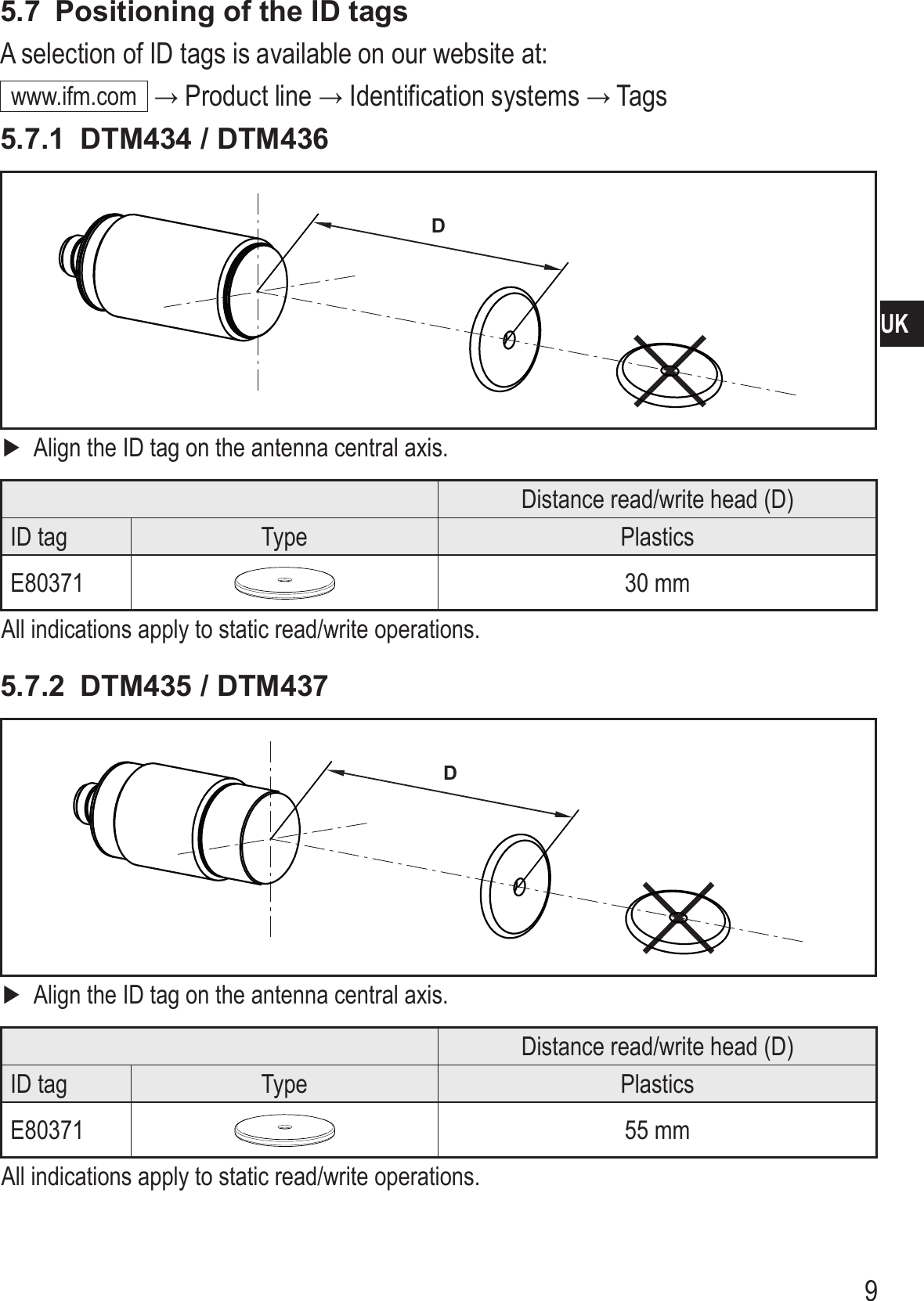
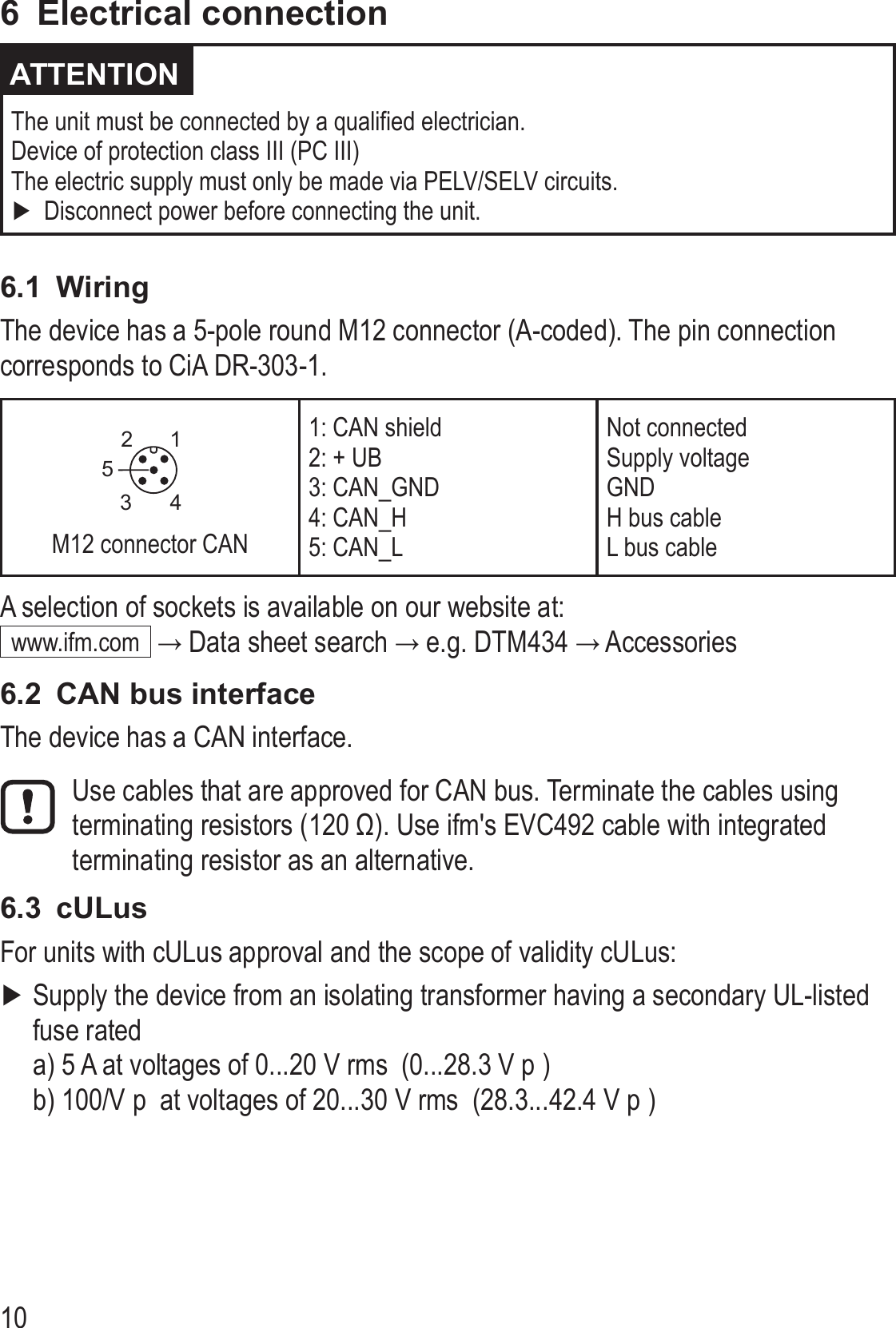
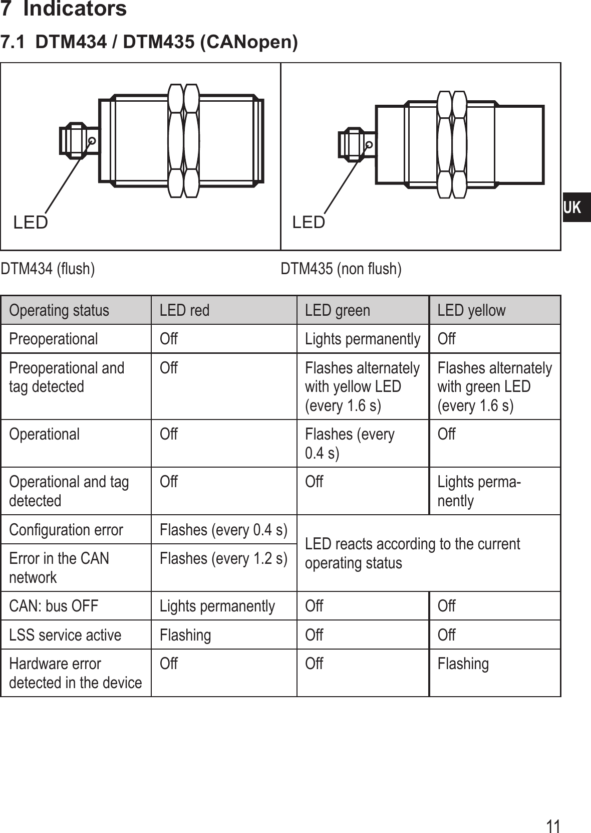
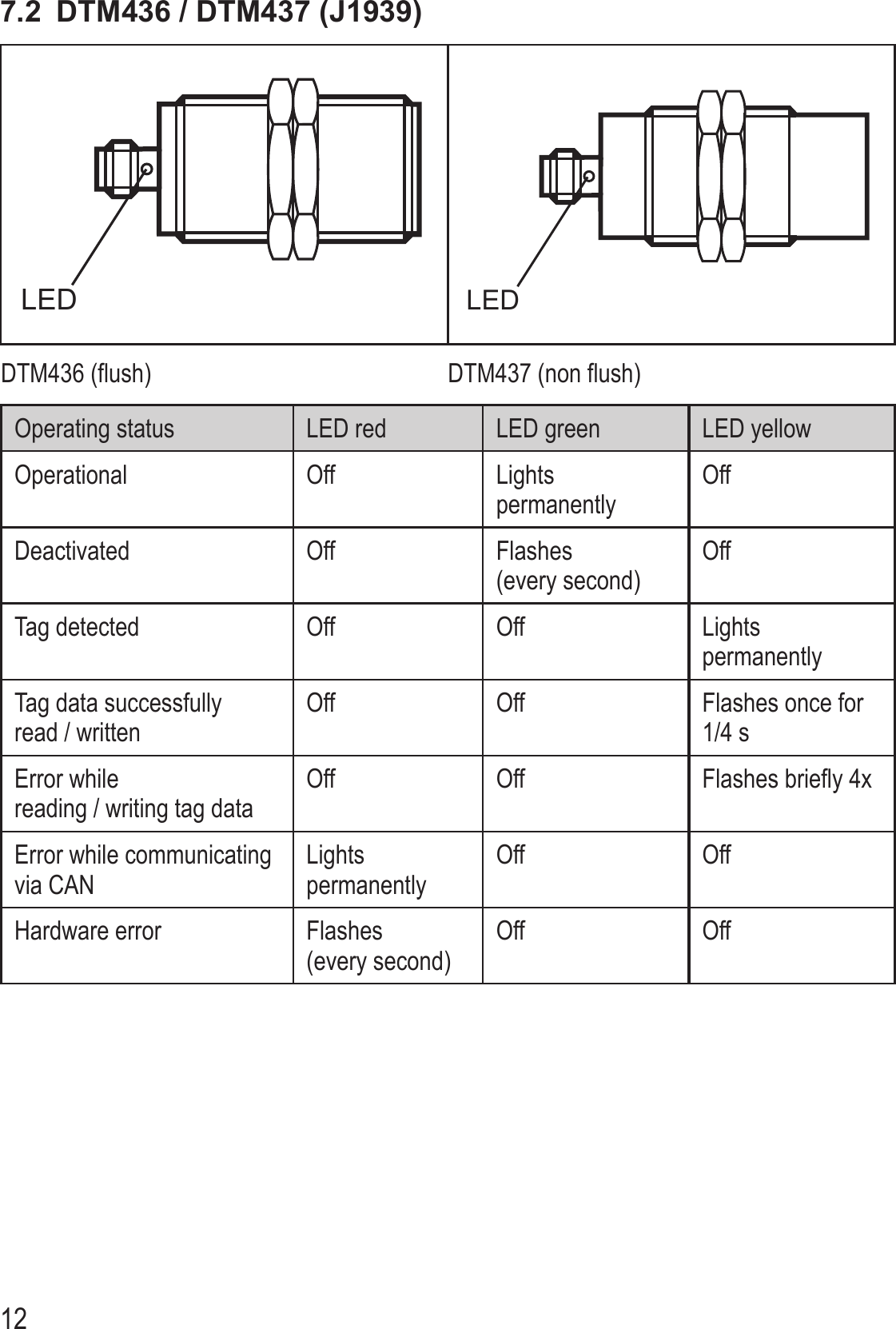
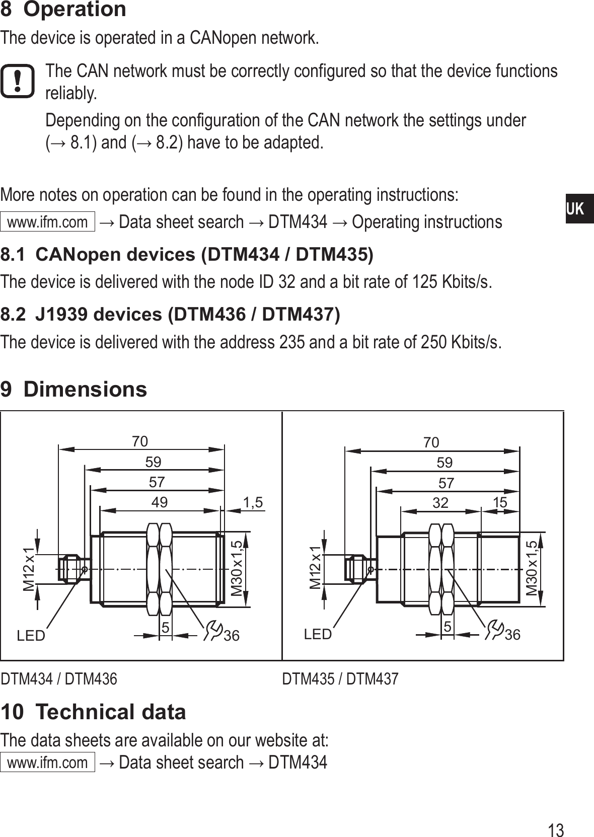
ifm electronic DTMHFIB RFID read/write head User Manual UserManual EN

ifm electronic gmbh RFID read/write head UserManual EN

Contents

UserManual_EN.pdf

Installation Instructions RF-identification system Read/write headDTM434DTM435DTM436DTM43780231613 / 00    09 / 2015UK
2Content1  Preliminary note ���������������������������������������������������������������������������������������������������41�1  Symbols used �����������������������������������������������������������������������������������������������41�2  Warnings used ����������������������������������������������������������������������������������������������42  Safety instructions �����������������������������������������������������������������������������������������������42�1 General ��������������������������������������������������������������������������������������������������������� 42�2  Radio equipment ������������������������������������������������������������������������������������������52�3  Interference of electronic and medical devices ��������������������������������������������53  Functions and features ����������������������������������������������������������������������������������������54 Function ���������������������������������������������������������������������������������������������������������������54�1  Operating principle ���������������������������������������������������������������������������������������54�2 Overview �������������������������������������������������������������������������������������������������������65 Installation������������������������������������������������������������������������������������������������������������65�1  General installation instructions ��������������������������������������������������������������������65�2  Notes on ID tag mounting �����������������������������������������������������������������������������65�3  Avoiding interference ������������������������������������������������������������������������������������75�4  Mechanical design ���������������������������������������������������������������������������������������� 75�5  Fixing example ���������������������������������������������������������������������������������������������75�6  Mounting distances ���������������������������������������������������������������������������������������85�6�1  DTM434 / DTM436 �������������������������������������������������������������������������������85�6�2  DTM435 / DTM437 �������������������������������������������������������������������������������85�7  Positioning of the ID tags ������������������������������������������������������������������������������95�7�1  DTM434 / DTM436 �������������������������������������������������������������������������������95�7�2  DTM435 / DTM437 �������������������������������������������������������������������������������96  Electrical connection ������������������������������������������������������������������������������������������106�1 Wiring ���������������������������������������������������������������������������������������������������������106�2  CAN bus interface ��������������������������������������������������������������������������������������106�3 cULus ���������������������������������������������������������������������������������������������������������107 Indicators ����������������������������������������������������������������������������������������������������������� 117�1  DTM434 / DTM435 (CANopen) ������������������������������������������������������������������ 117�2  DTM436 / DTM437 (J1939) ������������������������������������������������������������������������ 128 Operation �����������������������������������������������������������������������������������������������������������138�1  CANopen devices (DTM434 / DTM435) �����������������������������������������������������138�2  J1939 devices (DTM436 / DTM437) �����������������������������������������������������������13
3UK9 Dimensions ��������������������������������������������������������������������������������������������������������1310  Technical data �������������������������������������������������������������������������������������������������� 1311  Maintenance, repair and disposal ��������������������������������������������������������������������1412 Approvals/standards ����������������������������������������������������������������������������������������1412�1  Radio approvals ����������������������������������������������������������������������������������������1412�1�1 Overview �������������������������������������������������������������������������������������������1412�1�2 Europe ����������������������������������������������������������������������������������������������1412�1�3 USA ��������������������������������������������������������������������������������������������������1412�1�4 Canada ���������������������������������������������������������������������������������������������1512�1�5 Taiwan ����������������������������������������������������������������������������������������������1512�1�6 Australia �������������������������������������������������������������������������������������������� 1512�1�7  EC declaration of conformity ������������������������������������������������������������15
41  Preliminary noteThis document is part of the device and contains information about the correct handling of the product�This document is intended for specialists� These specialists are people who are qualified by their training and their experience to see risks and to avoid possible hazards that may be caused during operation or maintenance of the device�Read this document before use to familiarise yourself with operating conditions, installation and operation� Keep this document during the entire duration of use of the device�1.1  Symbols used►Instructions→Cross-referenceImportant note Non-compliance may result in malfunction or interference�Information Supplementary note1.2  Warnings used ATTENTION Warning of damage to property�2  Safety instructions2.1  GeneralObserve the operating instructions� Non-observance of the instructions, operation which is not in accordance with use as prescribed below, wrong installation or incorrect handling can affect the safety of operators and machinery�The installation and connection must comply with the applicable national and international standards� Responsibility lies with the person installing the device�The device must only be installed, connected and put into operation by a qualified electrician as the safe function of the device and machinery is only guaranteed when installation is correctly carried out�Disconnect the device externally before handling it�
5UKIn case of malfunction of the device or uncertainties please contact the manufacturer� Any tampering with the device can seriously affect the safety of operators and machinery� This is not permitted and leads to an exclusion of liability and warranty�2.2  Radio equipmentIn general, radio equipment must not be used in the vicinity of petrol stations, fuel depots, chemical plants or blasting operations� ►Do not transport and store any flammable gases, liquids or explosive substances near the unit�2.3  Interference of electronic and medical devicesOperation of the unit can affect the function of electronic devices that are not correctly shielded� ►Disconnect the device in the vicinity of medical equipment� ►Contact the manufacturer of the corresponding device in case of any interference�3  Functions and featuresThe device is suited for non-contact reading and writing of system-compliant RFID tags (ID tags)�Data transmission is done via the CAN bus�4  Function4.1  Operating principleThe ID tags are operated passively, i�e� without battery� The energy required for operation is supplied by the read/write head�The physical principle of the energy transfer is based on inductive coupling� The integrated antenna coil in the read/write head generates a magnetic field which partly penetrates the antenna coil of the ID tag� A voltage is generated by induction that supplies the data carrier with energy�
64.2  OverviewArt� no�:Function: Operating frequency:RFID standard:Type:DTM434 / DTM436read/write head13�56 MhzISO15693M30, flush mountableArt� no�:Function: Operating frequency:RFID standard:Type:DTM435 / DTM437read/write head13�56 MhzISO15693M30, non flush mountable5  Installation5.1  General installation instructionsWhen mounting several read/write heads adhere to the minimum distances between the systems�Flush mounting of a read/write head in metal reduces the read/write distance� The immediate vicinity of powerful HF emission sources such as welding transformers or converters can affect operation of the read/write heads�Information on the available mounting accessories is available on our website at: www�ifm�com  → Data sheet search → e.g. DTM434 → Accessories5.2  Notes on ID tag mountingInstallation of the ID tags in or on metal reduces the read and write distances� The orientation of the read/write head antenna axis must correspond with the axis of the ID tag coil�
7UK5.3  Avoiding interferenceThe device generates a modulated electrical field with a frequency of 13�56 MHz� To avoid interference of the data communication no other devices generating interference emission in this frequency band must be operated in its vicinity� Such devices are for example frequency converters and switched-mode power supplies�5.4  Mechanical design1:  Sensing face (DTM434 / DTM436) 1:  Sensing face (DTM435 / DTM437)5.5  Fixing example ►Fix the device using the supplied nuts (M30)�flush (DTM434 / DTM436) non flush (DTM434 / DTM436)
85.6  Mounting distances5.6.1  DTM434 / DTM436Operating mode Distance side (A) Distance front (B)For reading and writing ≥ 60 mm ≥ 120 mm5.6.2  DTM435 / DTM437Operating mode Distance side (A) Distance front (B)For reading and writing ≥ 100 mm ≥ 200 mm
9UK5.7  Positioning of the ID tagsA selection of ID tags is available on our website at:www�ifm�com  → Product line → Identification systems → Tags5.7.1  DTM434 / DTM436D ►Align the ID tag on the antenna central axis�Distance read/write head (D)ID tag Type PlasticsE80371 30 mmAll indications apply to static read/write operations�5.7.2  DTM435 / DTM437D ►Align the ID tag on the antenna central axis�Distance read/write head (D)ID tag Type PlasticsE80371 55 mmAll indications apply to static read/write operations�
106  Electrical connection ATTENTION The unit must be connected by a qualified electrician�Device of protection class III (PC III) The electric supply must only be made via PELV/SELV circuits� ►Disconnect power before connecting the unit�6.1  WiringThe device has a 5-pole round M12 connector (A-coded)� The pin connection corresponds to CiA DR-303-1�42 135M12 connector CAN1: CAN shield2: + UB3:  CAN _GND4: CAN_H5: CAN_LNot connectedSupply voltageGNDH bus cableL bus cableA selection of sockets is available on our website at: www�ifm�com  → Data sheet search → e.g. DTM434 → Accessories6.2  CAN bus interfaceThe device has a CAN interface�Use cables that are approved for CAN bus� Terminate the cables using terminating resistors (120 Ω). Use ifm's EVC492 cable with integrated terminating resistor as an alternative�6.3  cULusFor units with cULus approval and the scope of validity cULus: ►Supply the device from an isolating transformer having a secondary UL-listed fuse rated a) 5 A at voltages of 0���20 V rms  (0���28�3 V p ) b) 100/V p  at voltages of 20���30 V rms  (28�3���42�4 V p )
11UK7  Indicators7.1  DTM434 / DTM435 (CANopen)LED LEDDTM434 (flush) DTM435 (non flush)Operating status LED red LED green LED yellowPreoperational Off Lights permanently OffPreoperational andtag detectedOff Flashes alternately with yellow LED (every 1�6 s)Flashes alternately with green LED (every 1�6 s)Operational Off Flashes (every 0�4 s)OffOperational and tag detectedOff Off Lights perma-nentlyConfiguration error Flashes (every 0�4 s) LED reacts according to the current operating statusError in the CAN networkFlashes (every 1�2 s)CAN: bus OFF Lights permanently Off OffLSS service active Flashing Off OffHardware error detected in the deviceOff Off Flashing
127.2  DTM436 / DTM437 (J1939)LED LEDDTM436 (flush) DTM437 (non flush)Operating status LED red LED green LED yellowOperational Off Lights permanentlyOffDeactivated Off Flashes  (every second)OffTag detected Off Off Lights permanentlyTag data successfully  read / writtenOff Off Flashes once for 1/4 sError while  reading / writing tag dataOff Off Flashes briefly 4xError while communicating via CANLights permanentlyOff OffHardware error Flashes  (every second)Off Off
13UK8  OperationThe device is operated in a CANopen network� The CAN network must be correctly configured so that the device functions reliably� Depending on the configuration of the CAN network the settings under  (→ 8.1) and (→ 8.2) have to be adapted�More notes on operation can be found in the operating instructions:www�ifm�com  → Data sheet search → DTM434 → Operating instructions8.1  CANopen devices (DTM434 / DTM435)The device is delivered with the node ID 32 and a bit rate of 125 Kbits/s�8.2  J1939 devices (DTM436 / DTM437)The device is delivered with the address 235 and a bit rate of 250 Kbits/s�9  Dimensions5949M30x1,55770M12 x1LED1,55365932M30x1,5577015M12 x1LED 536DTM434 / DTM436 DTM435 / DTM43710  Technical dataThe data sheets are available on our website at: www�ifm�com  → Data sheet search → DTM434
1411  Maintenance, repair and disposal ►Do not open the housing as the device does not contain any components which can be maintained by the user� The device must only be repaired by the manufacturer� ►Dispose of the device in accordance with the national environmental regulations�12  Approvals/standards12.1  Radio approvals12.1.1  OverviewThe overview of the approval status of a unit is available on our website at: www�ifm�com  → Data sheet search → e.g. DTM434 → More information12.1.2  EuropeUse in all EU countries12.1.3  USAFCC note: This device complies with Part 15 of the FCC Rules� Operation is subject to the following two conditions:1�  This device must not cause harmful interference, and2�  this device must accept any interference received, including interference that may cause undesired operation�Changes or modifications made to this equipment not expressly approved by ifm may void the FCC authorization to operate this equipment�NOTE: This equipment has been tested and found to comply with the limits for a Class A digital device, pursuant to part 15 of the FCC Rules� These limits are designed to provide reasonable protection against harmful interference when the equipment is operated in a commercial environment� This equipment generates, uses and can radiate radio frequency energy and, if not installed and used in accordance with the instructions, may cause harmful interference to radio communications� Operation of this equipment in a residential area is likely to cause harmful interference in which case the user will be required to correct the interference at his own expense�
15UK12.1.4  CanadaIC note:This device complies with Industry Canada license-exempt RSS standards�  Operation is subject to the following two conditions:1�  The device may not cause interference, and 2�  the user of the device must accept any interference received, including interference that may cause undesired operation�12.1.5  TaiwanAdministrative Regulations on Low Power Radio Wave Devices warning Article 12Unless granted permission by NCC, no company, firm, or user shall alter the frequency, increase the transmitting power, or alter the original design characteristics or operating functions of an approved low-power radio-frequency device�Article 14Low-power radio-frequency devices shall not affect aircraft security nor interfere with legal communications� If such interference occurs, the user shall immediately cease operating the device until improvement is made and the interference no longer exists�Legal communications refers to the wireless telecommunication operations that comply with the Telecommunications Act� Low-power radio-frequency devices must accept any interference received from legal communications and ISM radio wave devices�12.1.6  AustraliaUse in Australia:    12.1.7  EC declaration of conformityYou can find the EC declaration of conformity on our website  at: www�ifm�com  → Data sheet search → DTM434 → More information

Navigation menu