ifm electronic DTRLFMC RFID Reader User Manual
ifm electronic gmbh RFID Reader
UserManual.wiki
>
ifm electronic
>
DTRLFMC User Manual
User Manual
Navigation menu
Upload a User Manual
Namespaces
Wiki Guide
HTML
PDF
Info
Views
User Manual
Discussion / Help
Navigation

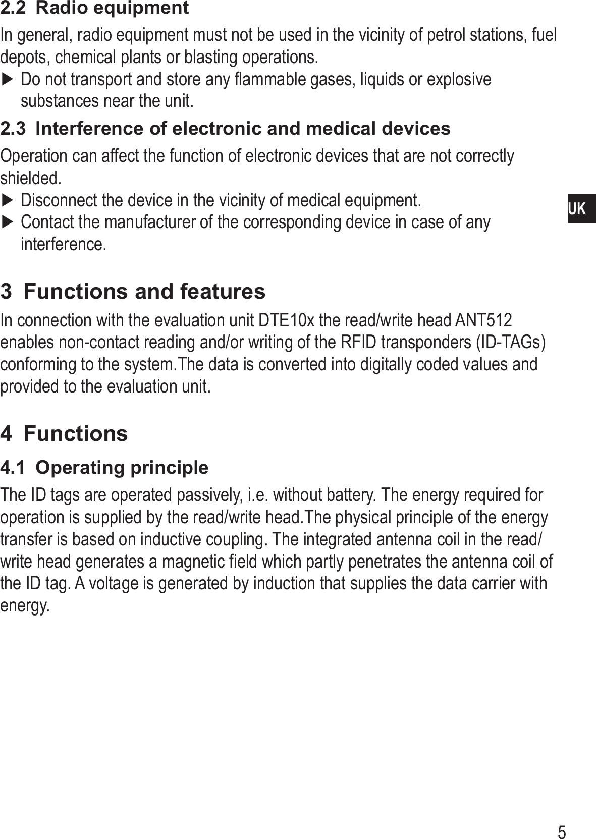
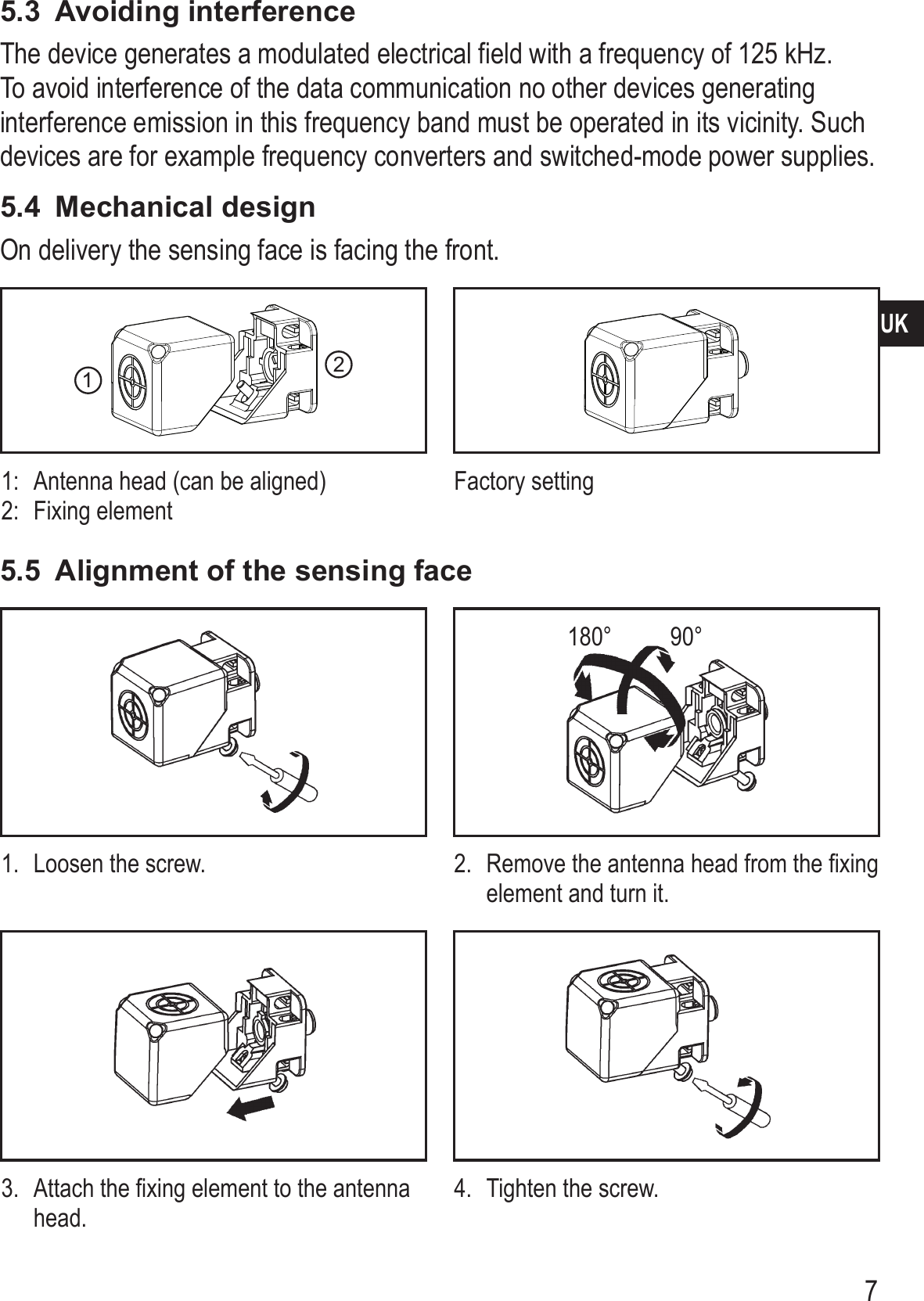
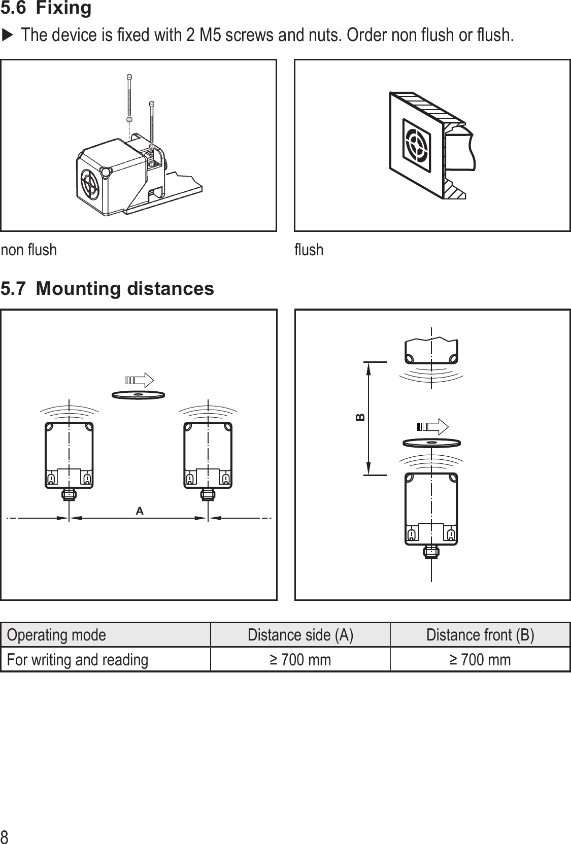
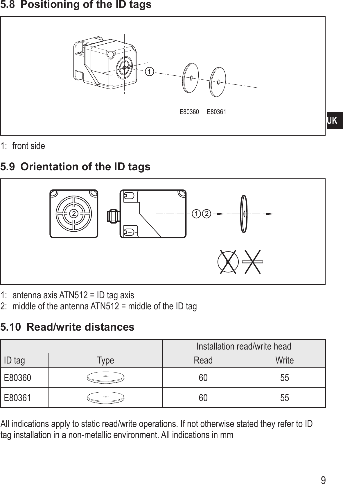
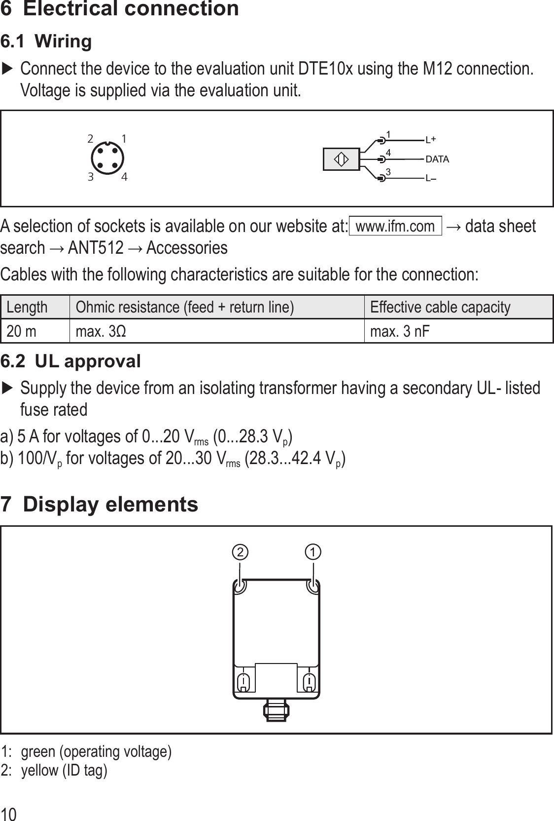
![64.2 OverviewArt. no.:Function:Type designation:Operating frequency:H X W X D [mm]:ANT512Read/write headDTRLF MCRWIDUS01125 kHz40 x 40 x 545 Installation5.1 General installation instructionsWhen mounting several read/write heads adhere to the minimum distances between the systems.Flush mounting of a read/write head in metal reduces the read/write distance. The immediate vicinity of powerful HF emission sources such as welding transformers or converters can affect operation of the read/write heads.Information on the available mounting accessories is available on our website at:www.ifm.com → data sheet search → ANT512 → Accessories5.2 Notes on ID tag mountingIf the ID tags are mounted in/on metal, the read/write distance is reduced. For positioning the ID tags the read/write heads are marked with an an-tenna symbol on the active face. It designates the middle of the integrated antenna coil and has to correspond with the middle of the ID tag.The orientation of the read/write head antenna axis must correspond with the axis of the ID tag coil.You can find out about the best way to position the available ID tags and on mounting in metal on our website:www.ifm.com → data sheet search → ANT512 → Additional data(General information about mounting and operation)](https://usermanual.wiki/ifm-electronic/DTRLFMC/User-Guide-1572916-Page-6.png)