ifm electronic DTS125-MC 125 kHz RFID writing/reading device User Manual
ifm electronic gmbh 125 kHz RFID writing/reading device
User Manual
Montageanleitung
RF-Identifikationssystem
mit integriertem AS-i Slave
Installation instructions
RF-identification system
with integrated AS-i slave
Notice de montage
Système d‘identification RFID
avec esclave AS-i intégré
DTS125
704153 / 06 05 / 2009
DE
UK
UK
FR
FR

2
Inhalt
1 Vorbemerkung .....................................................................................................4
1.1 Verwendete Symbole ....................................................................................4
2 Sicherheitshinweise .............................................................................................4
2.1 Allgemein ......................................................................................................4
2.2 Funkanlagen .................................................................................................5
2.3 Störung elektronischer und medizinischer Geräte ........................................5
3 Bestimmungsgemäße Verwendung .....................................................................5
4 Funktion ...............................................................................................................5
4.1 Funktionsweise .............................................................................................5
4.2 Typenübersicht .............................................................................................6
5 Montage ...............................................................................................................7
5.1 Generelle Montagehinweise .........................................................................7
5.2 Hinweise zur ID-TAG Montage .....................................................................7
5.3 DTA10x .........................................................................................................8
5.3.1 Befestigung ...........................................................................................8
5.3.2 Montageabstände .................................................................................8
5.3.3 Positionierung der ID-TAGs ..................................................................9
5.3.4 Ausrichtung der ID-TAGs ......................................................................9
5.3.5 Lese-/Schreibabstände .......................................................................10
5.4 DTA20x .......................................................................................................10
5.4.1 Mechanischer Aufbau .........................................................................10
5.4.2 Aktive Fläche ausrichten ..................................................................... 11
5.4.3 Befestigung ......................................................................................... 11
5.4.4 Montageabstände ...............................................................................12
5.4.5 Positionierung der ID-TAGs ................................................................12
5.4.6 Ausrichtung der ID-TAGs ....................................................................13
5.4.7 Lese-/Schreibabstände .......................................................................13
5.5 DTA30x .......................................................................................................14
5.5.1 Befestigung .........................................................................................14
5.5.2 Montageabstände ...............................................................................14
5.5.3 Positionierung der ID-TAGs ................................................................15
5.5.4 Ausrichtung der ID-TAGs ....................................................................15
5.5.5 Lese-/Schreibabstände .......................................................................15
5.5.6 Steckereinsatz drehen ........................................................................16

3
DE
6 Elektrischer Anschluss .......................................................................................17
6.1 Anschlussbelegung .....................................................................................17
6.2 Mindestabstand AS-i Leitung zum Gehäuse ..............................................17
6.2.1 DTA10x ...............................................................................................17
6.2.2 DTA20x ...............................................................................................18
6.2.3 DTA30x ...............................................................................................18
6.3 UL-Zulassung .............................................................................................19
7 Anzeigeelemente ...............................................................................................19
7.1 Lesebetrieb (Grundeinstellung) ..................................................................19
7.2 Schreibbetrieb (nur DTA100, DTA200, DTA300) ........................................20
8 Betrieb ...............................................................................................................21
8.1 Grundeinstellungen im AS-i Netzwerk ........................................................21
8.2 Adressierung ...............................................................................................21
8.3 Analogwert-Repräsentation ........................................................................21
8.4 Belegung der Datenbits ..............................................................................21
8.5 Codewert-Darstellung durch Datenbits D16...D1 .......................................22
8.6 Zusatzfunktionen gemäß AS-i Profil 7.4 .....................................................22
9 Maße..................................................................................................................23
9.1 DTA10x .......................................................................................................23
9.2 DTA20x .......................................................................................................23
9.3 DTA30x .......................................................................................................24
10 Technische Daten ............................................................................................24
11 Wartung, Instandsetzung und Entsorgung .......................................................24
12 Zulassungen/Normen ......................................................................................24
12.1 Funkzulassungen .....................................................................................24
12.1.1 Übersicht ..........................................................................................24
12.1.2 Europa ..............................................................................................24
12.1.3 Hinweise FCC (USA, Kanada) .........................................................25
12.1.4 China ................................................................................................25
12.1.5 Singapur ...........................................................................................26
12.2 EG-Konformitätserklärung ........................................................................26
4
Vorbemerkung1
Dieses Dokument gilt für alle Geräte des Typs DTS125.
Es ist Bestandteil des Gerätes und enthält Angaben zum korrekten Umgang mit
dem Produkt.
Dieses Dokument richtet sich an Fachkräfte. Dabei handelt es sich um Personen,
die aufgrund ihrer Ausbildung und ihrer Erfahrung befähigt sind, Risiken zu
erkennen und mögliche Gefährdungen zu vermeiden, die der Betrieb oder die
Instandhaltung des Gerätes verursachen kann.
Lesen Sie dieses Dokument vor dem Einsatz, damit Sie mit Einsatzbedingungen,
Installation und Betrieb vertraut werden. Bewahren Sie dieses Dokument während
der gesamten Einsatzdauer des Gerätes auf.
Verwendete Symbole1.1
►Handlungsanweisung
→Querverweis
Wichtiger Hinweis
Fehlfunktionen oder Störungen sind bei Nichtbeachtung möglich.
Information
Ergänzender Hinweis
Sicherheitshinweise2
Allgemein2.1
Befolgen Sie die Angaben dieser Anleitung. Nichtbeachten der Hinweise, Verwen-
dung außerhalb der nachstehend genannten bestimmungsgemäßen Verwendung,
falsche Installation oder Handhabung können Beeinträchtigungen der Sicherheit
von Menschen und Anlagen zur Folge haben.
Der Einbau und Anschluss muss den gültigen nationalen und internationalen
Normen entsprechen. Die Verantwortung trägt derjenige, der das Gerät installiert.
Das Gerät darf nur von einer Elektrofachkraft eingebaut, angeschlossen und in
Betrieb gesetzt werden, da die sichere Funktion des Gerätes und der Anlage nur
bei ordnungsgemäßer Installation gewährleistet ist.
Schalten Sie das Gerät extern spannungsfrei bevor Sie irgendwelche Arbeiten an
ihm vornehmen.

5
DE
Bei Fehlfunktion des Gerätes oder bei Unklarheiten bitte mit dem Hersteller in
Verbindung setzen. Eingriffe in das Gerät können schwerwiegende Beeinträchti-
gungen der Sicherheit von Menschen und Anlagen zur Folge haben. Sie sind nicht
zulässig und führen zu Haftungs- und Gewährleistungsauschluss.
Funkanlagen2.2
Funkgeräte dürfen generell nicht in der Nähe von Tankstellen, Kraftstoffdepots,
Chemiewerken oder Sprengarbeiten benutzt werden.
Keine entflammbaren Gase, Flüssigkeiten oder explosive Stoffe im Bereich des ►
Gerätes transportieren und lagern.
Störung elektronischer und medizinischer Geräte2.3
Der Betrieb kann die Funktionsfähigkeit von nicht ordnungsgemäß geschirmten
elektronischen Geräten beeinträchtigen.
Das Gerät in der Nähe medizinischer Geräte ausschalten. ►
Bei Störungen ggf. beim Hersteller des jeweiligen Gerätes informieren. ►
Bestimmungsgemäße Verwendung3
Das RF-Identifikationssystem DTS125 dient zum berührungslosen Lesen und/
oder Beschreiben systemkonformer RFID-Transponder (ID-TAGs).
Die Daten werden in digital codierte Werte gewandelt und der AS-i Steuerungse-
bene zur Verfügung gestellt (AS-i Master, Controller oder Host).
Einsatzbereiche sind z.B.:
Materialflusssteuerung und -kontrolle in Fertigungslinien●
Lagermanagement durch automatische Lagerguterkennung●
Behältermanagement, Kommissionierung oder die Warenverfolgung●
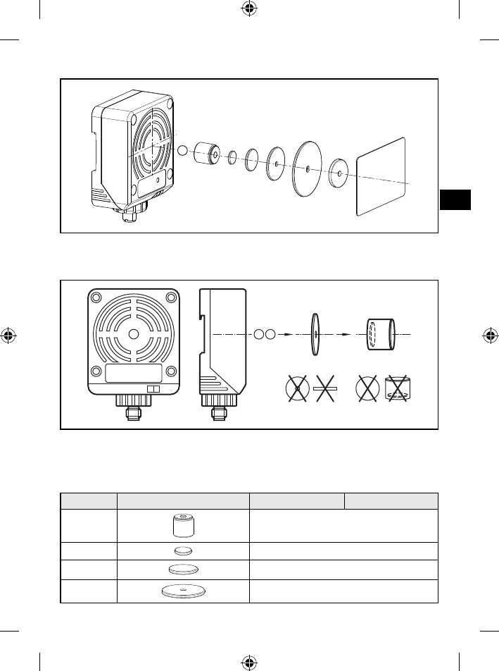
Funktion4
Funktionsweise4.1
Die ID-TAGs werden passiv betrieben, d.h. ohne Batterie. Die zum Betrieb not-
wendige Energie wird vom Lese-/Schreibkopf aufgebracht.
Das physikalische Prinzip der Energieübertragung beruht auf der induktiven
Kopplung. Die integrierte Antennenspule des Lese-/Schreibkopfes erzeugt ein ma-
gnetisches Feld, das zu einem Teil die Antennenspule des ID-TAGs durchdringt.
Durch Induktion wird dort eine Spannung erzeugt die den Datenträger mit Energie
versorgt.
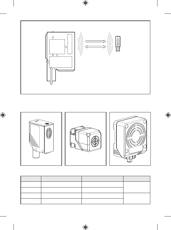
6
display
HF and
analogue
circuit
µcontroller and
AS-interface
antenna
energy
data
read/write head ID tag
AS-i master,
controller or host
Funktion (Beispiel Lese-/Schreibkopf DTA100 und ID-TAG E80301)
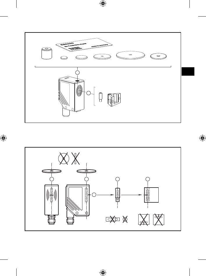
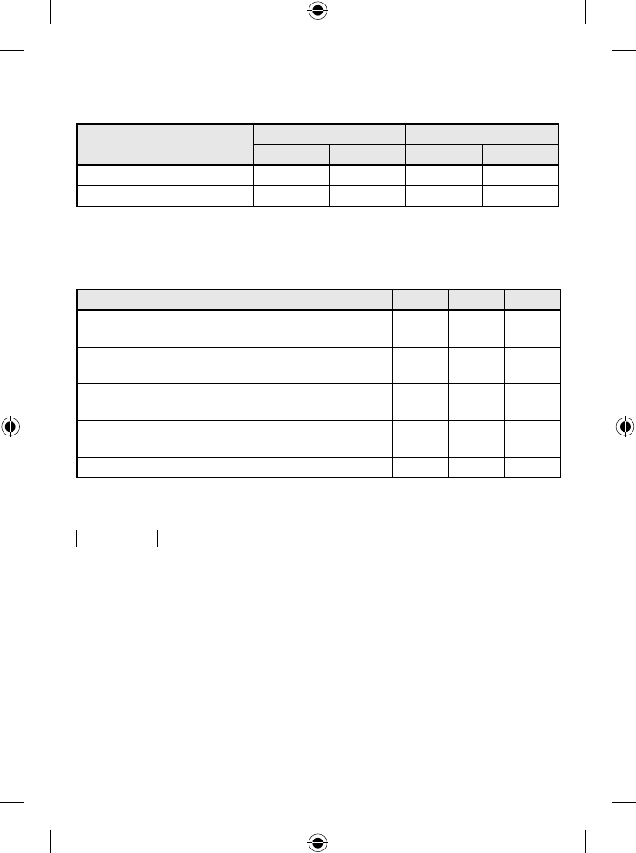
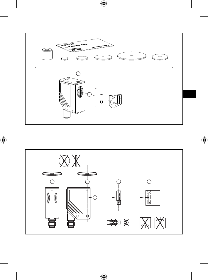
Typenübersicht4.2
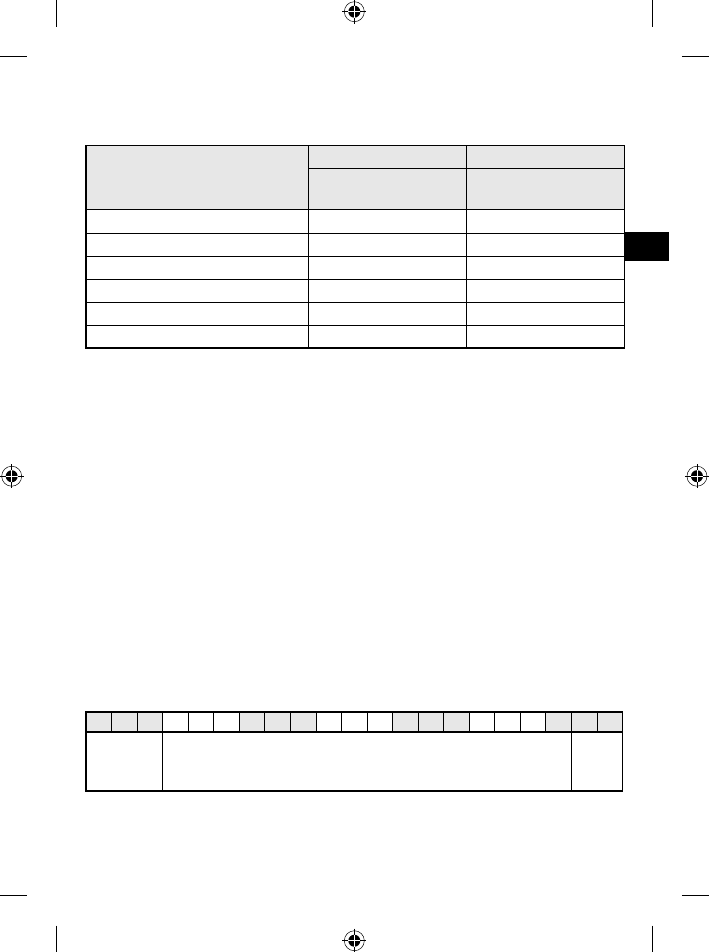
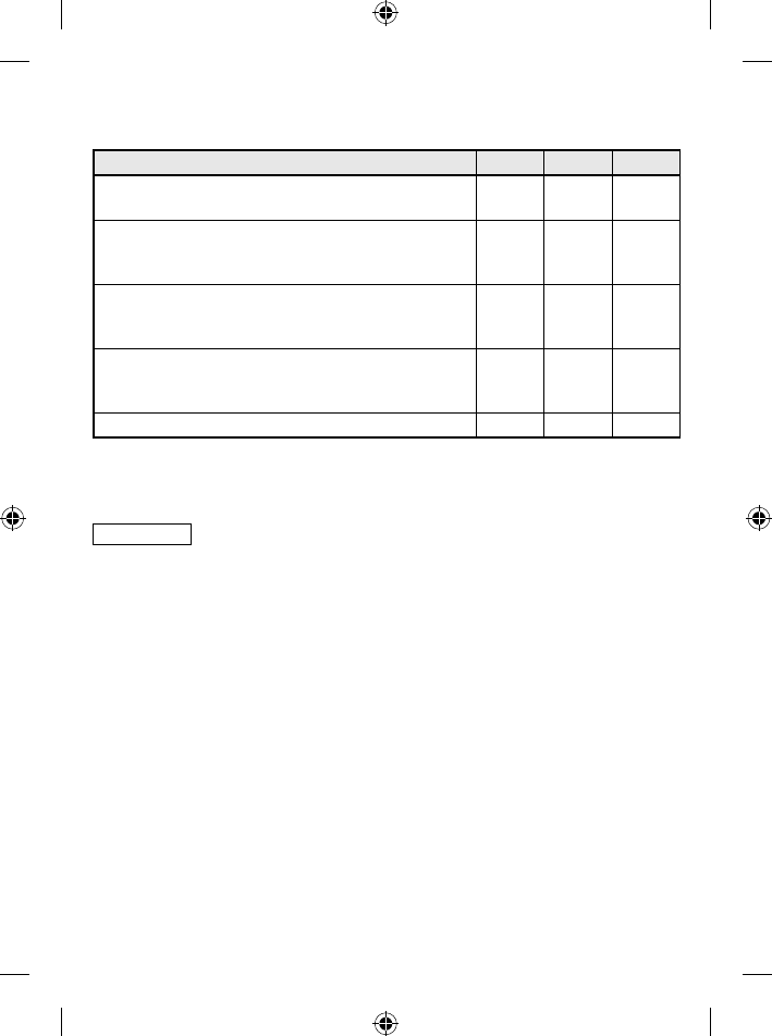
DTA10x DTA20x DTA30x
Art.-Nr. Funktion Typbezeichnung H x B x T [mm]
DTA100 Lese-/Schreibkopf DTS125 AARWASUS 55 x 24 x 41
DTA101 Lesekopf DTS125 AAROASUS
DTA200 Lese-/Schreibkopf DTS125 MCRWASUS 40 x 40 x 54
DTA201 Lesekopf DTS125 MCROASUS
7
DE
Art.-Nr. Funktion Typbezeichnung H x B x T [mm]
DTA300 Lese-/Schreibkopf DTS125 DCRWASUS 92 x 80 x 40
DTA301 Lesekopf DTS125 DCROASUS
Montage5
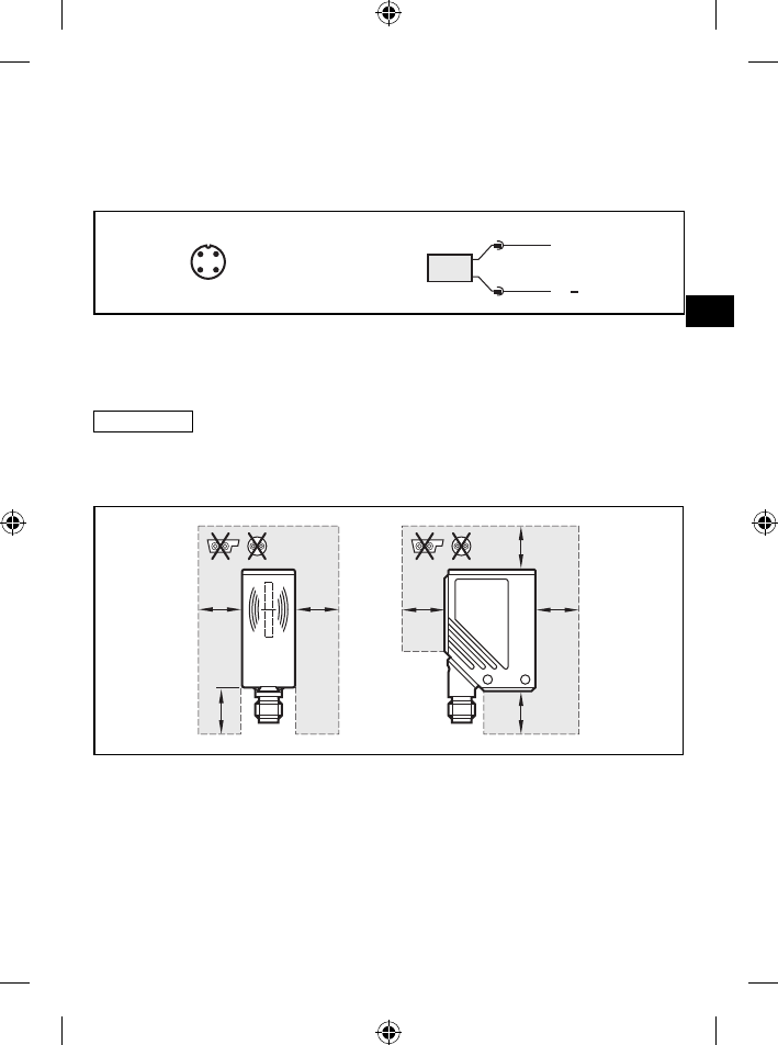
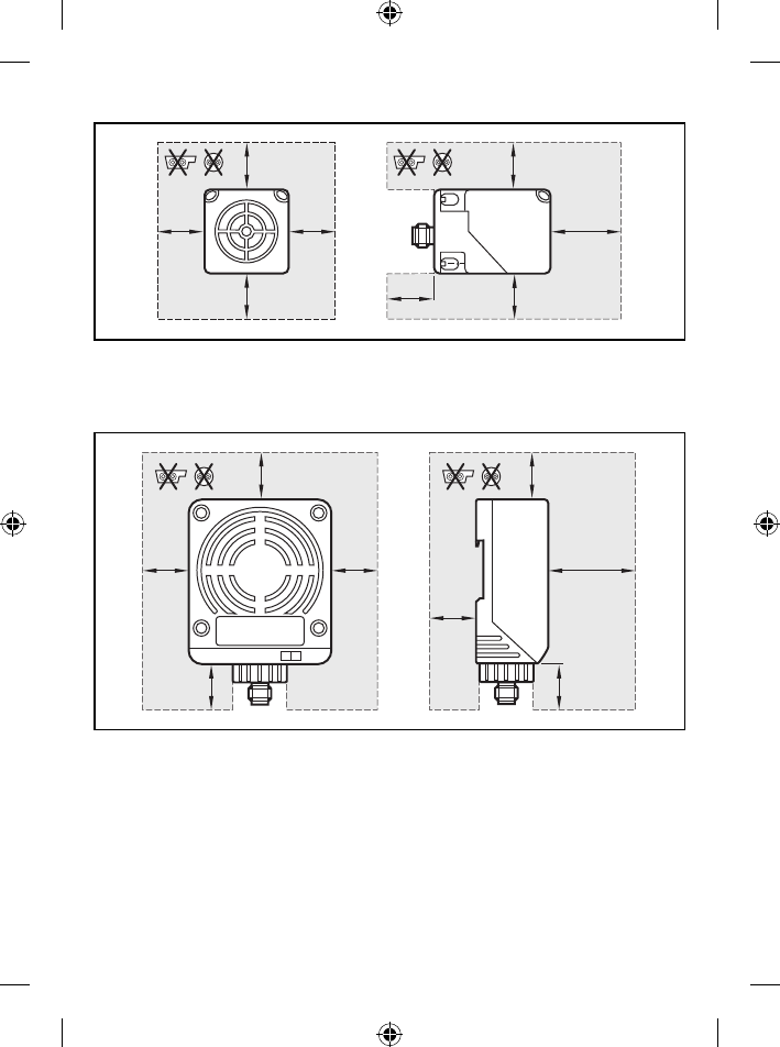
Generelle Montagehinweise5.1
Bei der Montage von mehreren Systemen die Mindestabstände zwischen
den Lese-/Schreibköpfen beachten.
Der bündige Einbau eines Lese-/Schreibkopfes in Metall verringert den
Lese-/Schreibabstand.
Die unmittelbare Nähe starker HF-Emissionsquellen, wie z.B. Schweißtra-
fos oder Umformer, kann die Funktion der Lese-/Schreibköpfe beeinträch-
tigen.
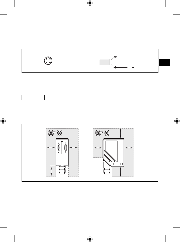
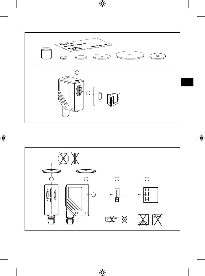
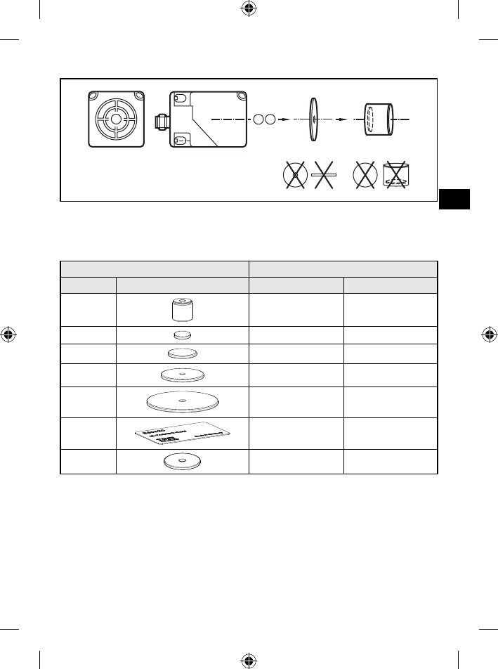
Informationen zum erhältlichen Montagezubehör sind im Internet abrufbar unter:
www.ifm.com → Datenblatt-Suche → z.B. DTA100 → Zubehör
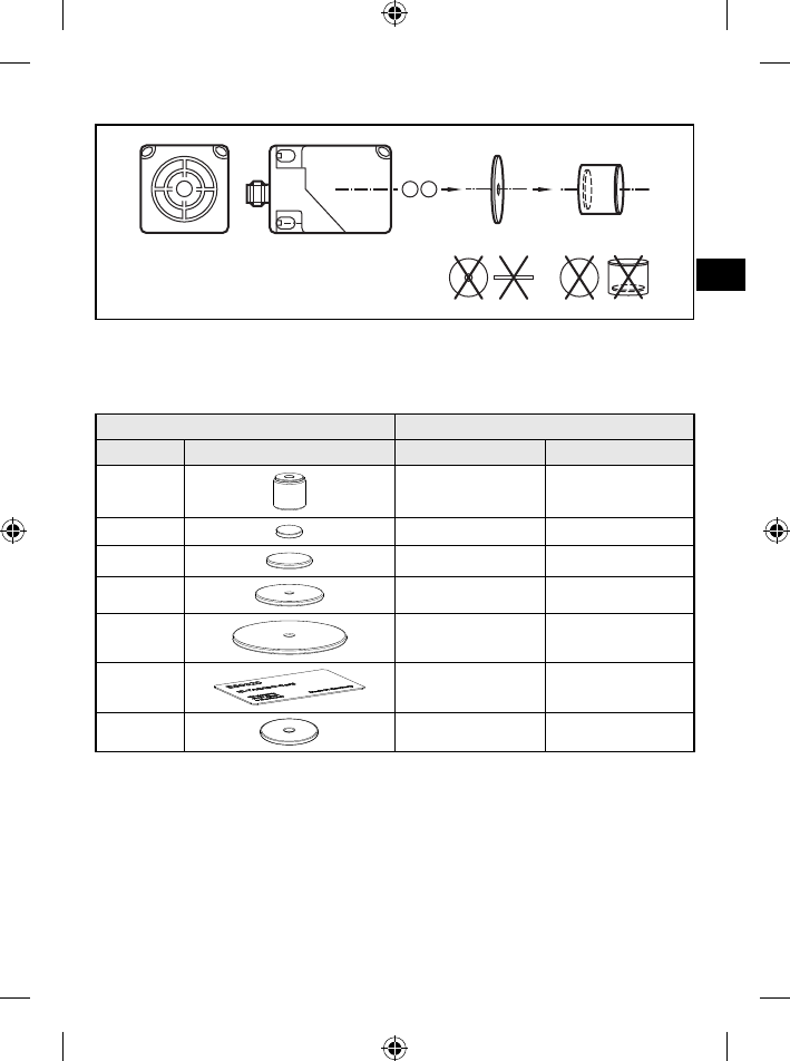
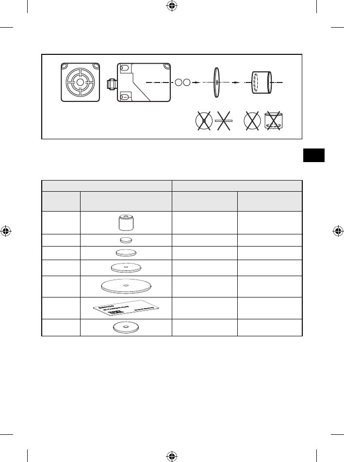
Hinweise zur ID-TAG Montage5.2
Die Montage der ID-TAGs in/auf Metall verringert den Lese-/Schreibab-
stand.
Zur Positionierung der ID-TAGs sind die Lese-/Schreibköpfe auf der aktiven
Fläche mit einem Antennensymbol versehen. Es kennzeichnet die Mitte der
integrierten Antennenspule und muss mit der ID-TAG Mitte übereinstimmen.
Die Ausrichtung der Lese-/Schreibkopf-Antennenachse muss mit der Achse
der ID-TAG Spule übereinstimmen.
Angaben zur optimalen Positionierung der erhältlichen ID-TAGs und zum
Einbau in Metall sind im Internet abrufbar unter:
www.ifm.com → Datenblatt-Suche → z.B. DTA100 → weitere Informationen
(Grundlagen für Montage und Betrieb)
8
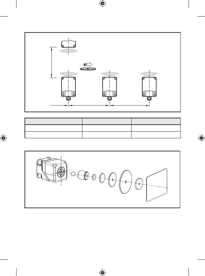
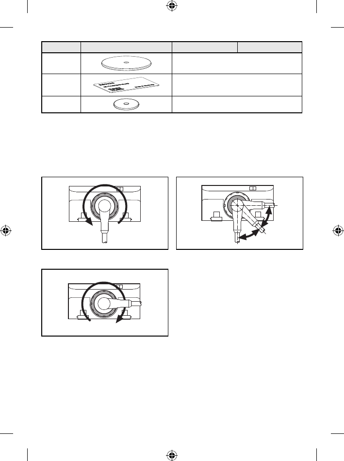
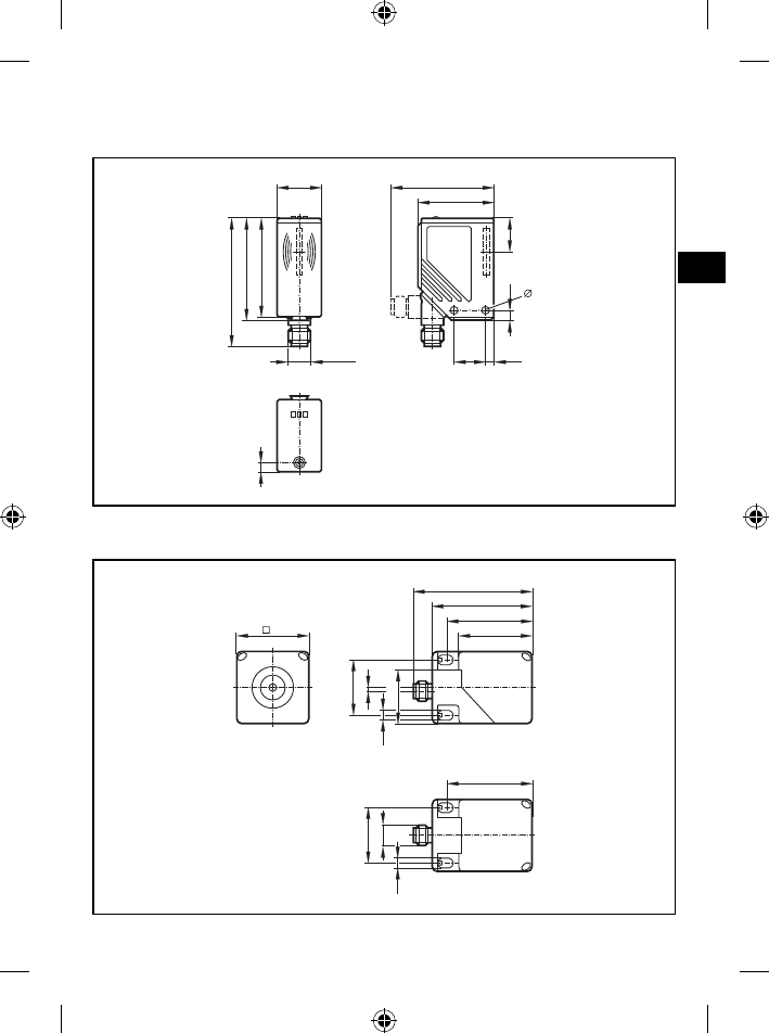
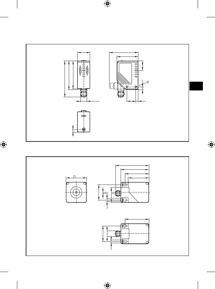
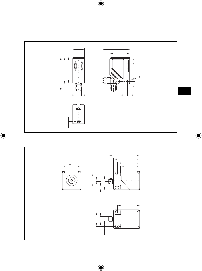
DTA10x5.3
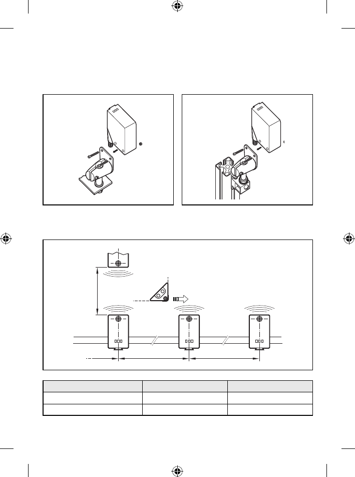
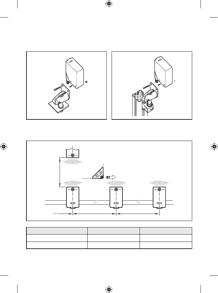
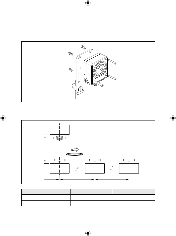
Befestigung5.3.1
Das Gerät wahlweise mit 2 Stk. M4 Schrauben und Muttern oder mittels ►
Klemmhalterung befestigen.
Montagebeispiel E20898 Montagebeispiel E20901
Montageabstände5.3.2
A A
B
Betriebsart Abstand seitlich (A) Abstand frontal (B)
Nur Lesen ≥ 200 mm ≥ 200 mm
Lesen und Schreiben ≥ 400 mm ≥ 400 mm
9
DE
Positionierung der ID-TAGs5.3.3
E80311 E80312 E80317 E80318 E80319
E80320
E80301 E80302
2
1
E80322
Frontseite1:
Überkopf2:
Ausrichtung der ID-TAGs5.3.4
1
2
1 11
Antennenachse DTA10x = Achse ID-TAG1:
Antennenmitte DTA10x = Mitte ID-TAG2:
10
Lese-/Schreibabstände5.3.5
ID-TAG Bauform Positionierung Lesen Schreiben
E80301
Frontseite
20 10
E80302 20 10
E80311
Überkopf
5...20
8*
E80312 5...20
E80317 10...28
E80318 15...40
E80319 20...60 20...50
E80320 18...60
E80322 15...40
Alle Angaben gelten für statische Lese-/Schreibvorgänge. Wenn nicht anders angegeben,
beziehen sie sich auf den ID-TAG Einbau in eine nicht-metallische Umgebung.
Alle Angaben in mm
*) ID-TAG Einbau bündig in Metall
DTA20x5.4
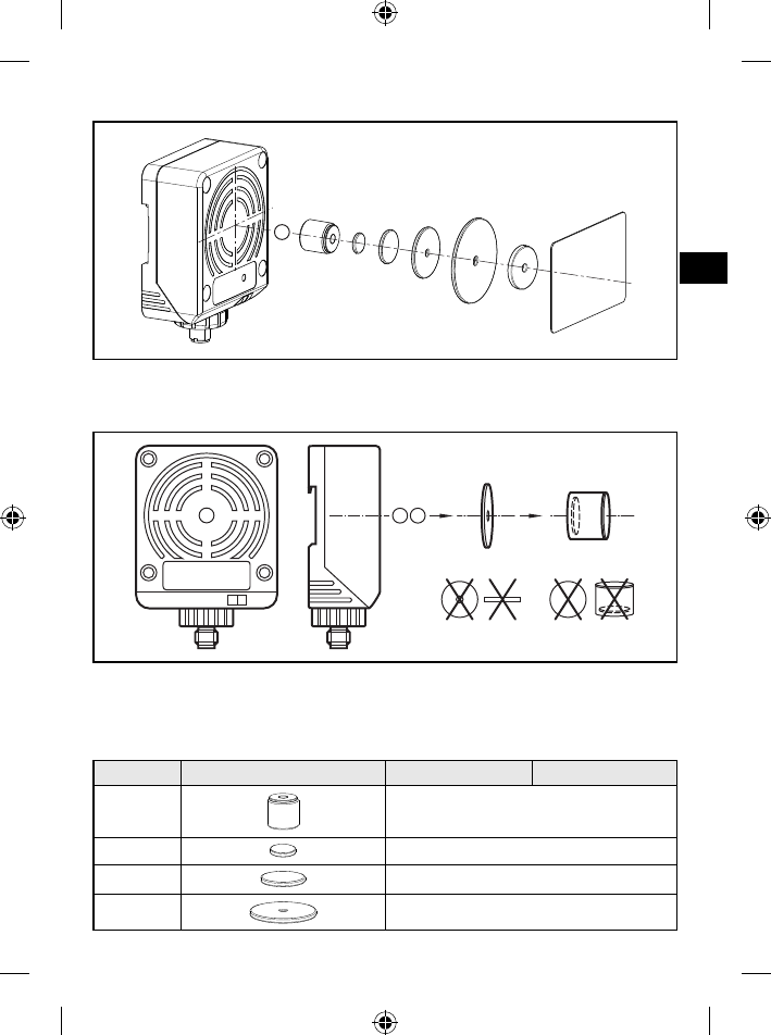
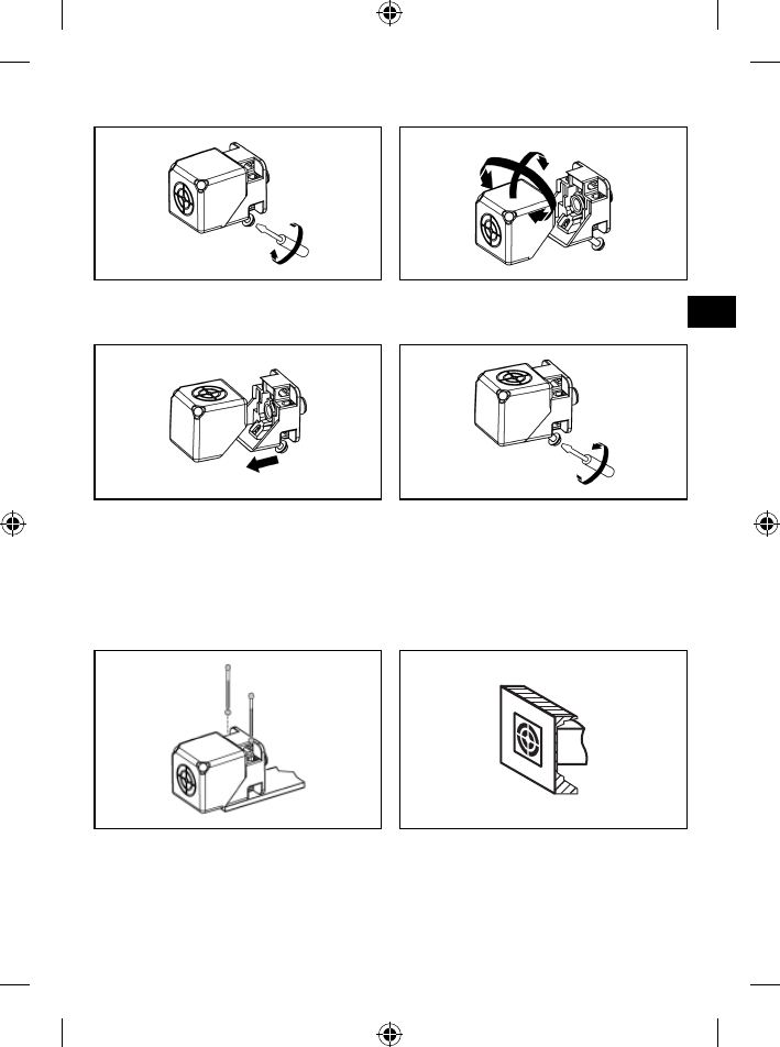
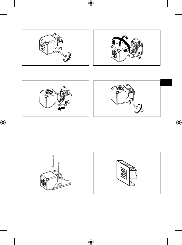
Mechanischer Aufbau5.4.1
Die aktive Fläche ist im Lieferzustand nach vorne gerichtet.
2
1
Antennenkopf (ausrichtbar)1:
Befestigungselement2:
Lieferzustand
11
DE
Aktive Fläche ausrichten5.4.2
180° 90°
Schraube lösen.1. Antennenkopf vom Befestigungselement 2.
trennen und drehen.
Befestigungselement und Antennenkopf 3.
zusammenstecken.
Schraube anziehen.4.
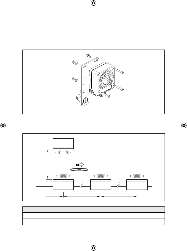
Befestigung5.4.3
Das Gerät mit 2 Stk. M4 Schrauben und Muttern befestigen. ►
Wahlweise nicht bündig oder bündig.
nicht bündig bündig
12
Montageabstände5.4.4
A A
B
Betriebsart Abstand seitlich (A) Abstand frontal (B)
Nur Lesen ≥ 150 mm ≥ 150 mm
Lesen und Schreiben ≥ 300 mm ≥ 300 mm
Positionierung der ID-TAGs5.4.5
E80311 E80312 E80317 E80318 E80319 E80320
1
E80322
Frontseite1:
13
DE
Ausrichtung der ID-TAGs5.4.6
21
2
Antennenachse DTA20x = Achse ID-TAG1:
Antennenmitte DTA20x = Mitte ID-TAG2:
Lese-/Schreibabstände5.4.7
Einbau Lese-/Schreibkopf
ID-TAG Bauform nicht bündig bündig in Metall
E80311 25 22
E80312 25 22
E80317 35 28
E80318 55 36
E80319 65 45
E80320 60 40
E80322 55 36
Alle Angaben gelten für statische Lese-/Schreibvorgänge. Wenn nicht anders angegeben,
beziehen sie sich auf den ID-TAG Einbau in eine nicht-metallische Umgebung.
Alle Angaben in mm
14
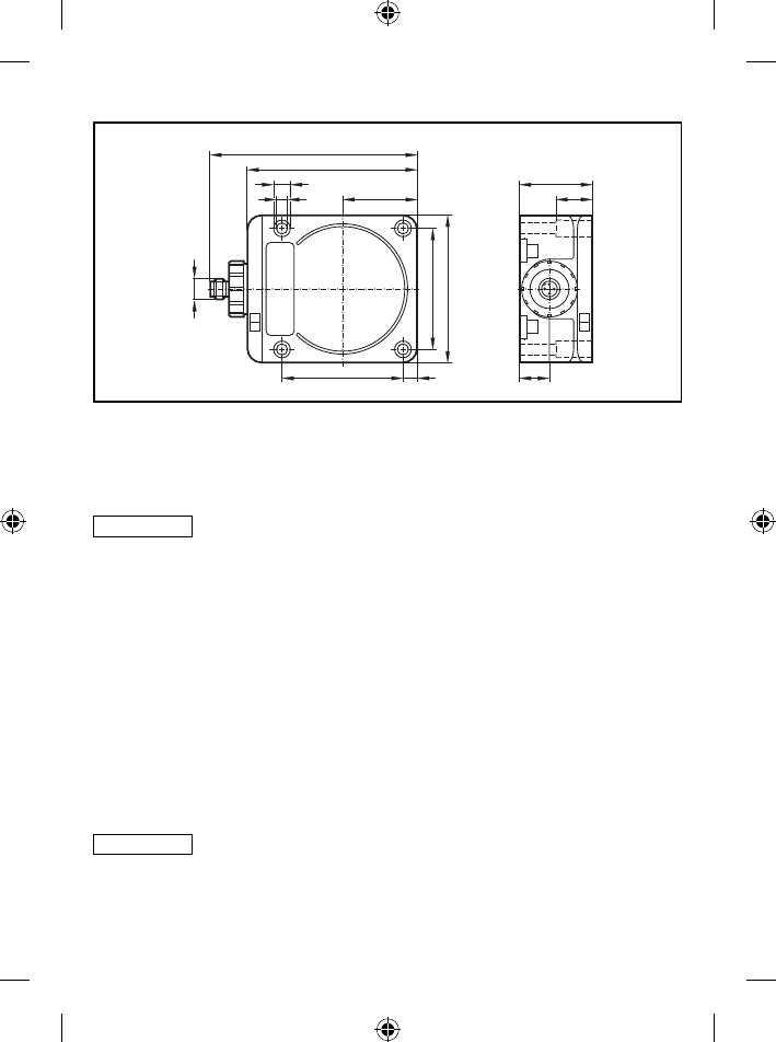
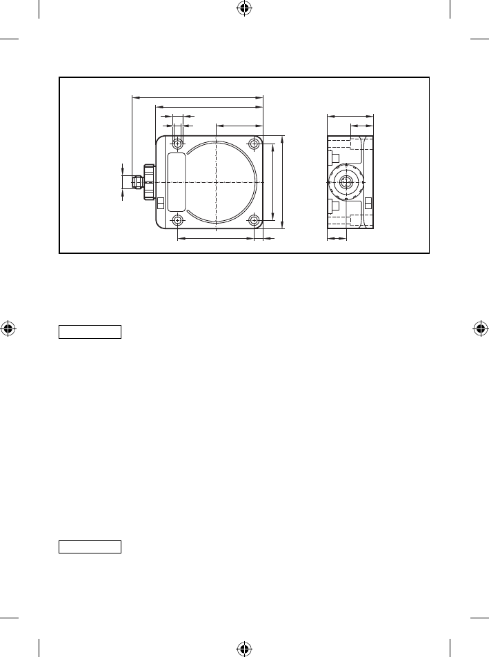
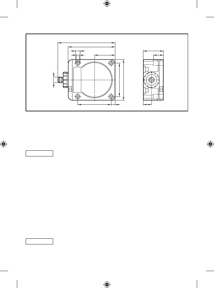
DTA30x5.5
Befestigung5.5.1
Das Gerät wahlweise auf einer 35 mm Normschiene oder mit 4 Stk. M5 ►
Schrauben und Muttern befestigen.
Montagebeispiel E11122
Montageabstände5.5.2
A A
B
Betriebsart Abstand seitlich (A) Abstand frontal (B)
Nur Lesen ≥ 280 mm ≥ 400 mm
Lesen und Schreiben ≥ 500 mm ≥ 500 mm
15
DE
Positionierung der ID-TAGs5.5.3
1
E80311 E80312 E80317 E80318 E80319 E80320E80322
Frontseite1:
Ausrichtung der ID-TAGs5.5.4
221
Antennenachse DTA30x = Achse ID-TAG1:
Antennenmitte DTA30x = Mitte ID-TAG2:
Lese-/Schreibabstände5.5.5
ID-TAG Bauform Lesen Schreiben
E80311 35
E80312 40
E80317 50
E80318 80
16
ID-TAG Bauform Lesen Schreiben
E80319 110
E80320 90
E80322 80
Alle Angaben gelten für statische Lese-/Schreibvorgänge. Wenn nicht anders angegeben,
beziehen sie sich auf den ID-TAG Einbau in eine nicht-metallische Umgebung.
Alle Angaben in mm
Steckereinsatz drehen5.5.6
Der Steckereinsatz ist in 45°-Schritten drehbar.
1. Überwurfmutter lösen 2. Steckereinsatz herausziehen und drehen
3. Überwurfmutter festziehen
17
DE
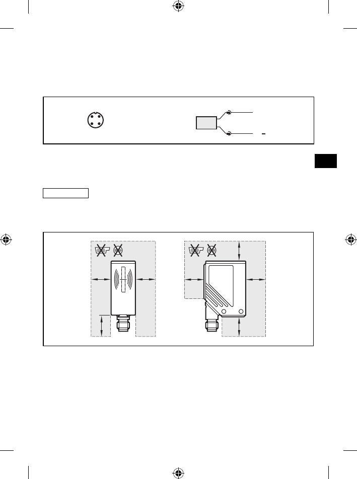
Elektrischer Anschluss6
Anschlussbelegung6.1
Das Gerät über die M12-Steckverbindung mit dem AS-i-Netz verbinden. Die ►
Spannungsversorgung erfolgt aus dem AS-i-Netz.
4
21
3
ASI+
ASI
1
3
BN
BU
Anschlussbelegung und Adernfarben bei ifm-Kabeldosen
1 = BN (braun)
2 = BU (blau)
Eine Auswahl an Kabeldosen ist im Internet abrufbar unter:
www.ifm.com → Datenblatt-Suche → z.B. DTA100 → Zubehör
Mindestabstand AS-i Leitung zum Gehäuse6.2
DTA10x6.2.1
AA AA
AA
A
A) 100 mm

18
DTA20x6.2.2
AA
A
A
A
A
B
A
A) 50 mm
B) 100 mm
DTA30x6.2.3
AA
A
A
B
A
A
A
A) 250 mm
B) 500 mm
19
DE
UL-Zulassung6.3
Folgender Hinweis gilt nur für die Geräte DTA20x und DTA30x.
Das Gerät von einer galvanisch getrennten Quelle versorgen, die sekundär ►
über eine UL-zugelassene Sicherung mit folgendem max. Nennstrom verfügt.
a) 5 A bei Spannungen von 0...20 Vrms (0...28,3 Vp)
b) 100/Vp bei Spannungen von 20...30 Vrms (28,3...42,4 Vp)
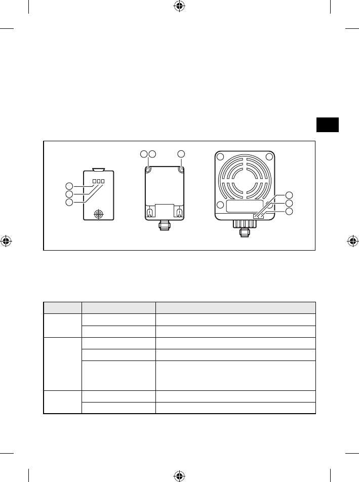
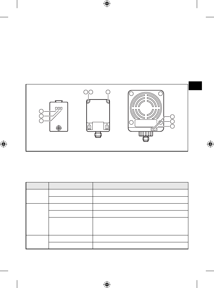
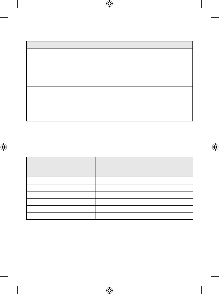
Anzeigeelemente7
DTA10x DTA30xDTA20x
3
2
1
2
3
1
32 1
grün (Betriebsspannung)1:
gelb (ID-TAG)2:
rot (AS-i Datenkommunikation)3:
Lesebetrieb (Grundeinstellung)7.1
LED Zustand Bedeutung
grün EIN Betriebsspannung ok
AUS Betriebsspannung fehlt
gelb EIN (Impuls) ID-TAG erfolgreich gelesen
EIN (permanent) ID-TAG erfolgreich gelesen und noch im Feld
AUS kein ID-TAG im Feld
oder fehlerhafter ID-TAG im Feld
oder ungültiger ID-TAG im Feld
rot EIN Fehler AS-i Datenkommunikation
AUS AS-i Datenkommunikation ok
20
Schreibbetrieb (nur DTA100, DTA200, DTA300)7.2
LED Zustand Bedeutung
grün/rot EIN/AUS wie Lesebetrieb
gelb EIN (Impuls) ID-TAG erfolgreich beschrieben
AUS kein ID-TAG im Feld
oder fehlerhafter ID-TAG im Feld
oder ungültiger ID-TAG (falsche Kennung)
gelb 500 ms blinkend ID-TAG beschreiben nicht möglich
ID-TAG nicht formatiert –
ID-TAG nicht im Erfassungsbereich –
ID-TAG mit Lockbit geschützt –
Wert außerhalb des Wertebereiches –
ungültiger Befehl –
21
DE
Betrieb8
Grundeinstellungen im AS-i Netzwerk8.1
Parameter Lese-/Schreibkopf Lesekopf
DTA100, DTA200,
DTA300
DTA101, DTA201,
DTA301
AS-i Profil 7.4 7.3
I/O Code 7 7
ID Code 4 3
Extended ID2 Code C C
ID1 Code für Codewert F F
Slave-Adresse (Werkseinstellung) 0 0
Codewerte im Hex-Format
Adressierung8.2
Der Lese-/Schreibkopf wird adressiert mit einem Adressiergerät (z.B. AC1144),
dem Master oder mit der AS-i-Software des Hosts (die Komponenten müssen AS-i
Version 2.1 unterstützen).
Eine Adresse zwischen 1 und 31 vergeben. ►
Analogwert-Repräsentation8.3
Für das AS-Interface ist der Lese-/Schreibkopf ein Analogeingang-Slave mit
Übertragungsprotokoll nach Profil 7.4 bzw. 7.3 (siehe oben). Arbeitet der Master
gemäß Master-Profil M3 oder M4, erkennt er den Lese-/Schreibkopf automatisch
und unterstützt das Profil 7.4.
Im Bereich der Analogwertübertragung sind die Profile 7.3 und 7.4 identisch.
Belegung der Datenbits8.4
In einem Übertragungszyklus werden folgende Daten in Datentripel übertragen:
E1 E2 E3 D16 D15 D14 D13 D12 D11 D10 D9 D8 D7 D6 D5 D4 D3 D2 D1 O V
Extension
bits
(statisch 0)
User Data Bits
Additional Information Bits:
O = Overflow-Bit (wird bei den Werten 7FFF und 8000 Hex. gesetzt, sonst 0)
V = Valid-Bit (wird bei einem gültigen Wert gesetzt)

22
Codewert-Darstellung durch Datenbits D16...D18.5
Die Darstellung des ID-Wertes erfolgt als vorzeichenbehaftete 16 Bit Zahl.
Bereich Dezimal Hex
von bis von bis
Wertebereich 0 32767 0 7FFF
Meldebereich -1 -32768 FFFF 8000
Wert 0 = kein ID-TAG im Lesebereich oder ID-TAG nicht erkannt.
Zusatzfunktionen gemäß AS-i Profil 7.48.6
(Nur gültig für Lese-/Schreibköpfe)
Funktion, Beschreibung DTA100 DTA200 DTA300
Read ID String
AS-i Slave informationen abfragen ●●●
Read Diagnosis String
Statistiken über Lese-/Schreibvorgänge abfragen ●●●
Read Parameter String
Daten vom ID-TAG rücklesen – ●●
Write Parameter String
Daten auf ID-TAG schreiben ●●●
Daten vom ID-TAG anfordern – ●●
● = Funktion implementiert
Beschreibung, Beispiele und Software für diverse Steuerungen unter:
www.ifm.com → Service → Download
23
DE
Maße9
DTA10x9.1
5
41
4,517
56
17
4,2
5,5
M12 x1
24
55
70
53,5
DTA20x9.2
40
66
40
54
M12 x1
30
30
2
46
46
5,5
5,5 29,5
24
DTA30x9.3
92
80
40
7,5
65
65
5,5
9,3
M12 x1
112
40
17
20
Alle Angaben in mm
Technische Daten10
Die Datenblätter sind im im Internet abrufbar unter:
www.ifm.com → Datenblatt-Suche → z.B. DTA100
Wartung, Instandsetzung und Entsorgung11
Da innerhalb des Gerätes keine vom Anwender zu wartenden Bauteile enthal- ►
ten sind, das Gehäuse nicht öffnen. Die Instandsetzung des Gerätes darf nur
durch den Hersteller durchgeführt werden.
Das Gerät gemäß den nationalen Umweltvorschriften entsorgen. ►
Zulassungen/Normen12
Funkzulassungen12.1
Übersicht12.1.1
Die Übersicht zum Zulassungsstand eines Gerätes ist im Internet abrufbar unter:
www.ifm.com → Datenblatt-Suche → z.B. DTA300 → Zulassungen
Europa12.1.2
Intended use: Verwendung in allen EU Staaten
25
DE
Hinweise FCC (USA, Kanada)12.1.3
Dieses Gerät erfüllt den Teil 15 der Bestimmungen der FCC und die RSS-210 der
Industry Canada. Der Betrieb setzt die folgenden zwei Bedingungen voraus:
(1) Dieses Gerät darf keine schädlichen Störungen verursachen und
(2) dieses Gerät muss eine Beeinflussung tolerieren, einschließlich einer Beein-
flussung, die einen unerwünschten Betrieb verursachen kann.
Warnhinweis:
Änderungen, die an diesem Gerät ohne ausdrückliche Genehmigung der ifm
electronic gmbh durchgeführt werden, können die Genehmigung der FCC, dieses
Gerät zu betreiben, ungültig machen.
Hinweis:
Dieses Gerät wurde getestet und erfüllt die Bestimmungen hinsichtlich der Be-
schränkungen für digitale Geräte der Klasse B gemäß Teil 15 der FCC Bestim-
mungen.
Diese Beschränkungen dienen dem angemessenen Schutz vor schädlichen Stö-
rungen, wenn das Gerät in einem Wohngebiet betrieben wird.
Dieses Gerät erzeugt und verwendet Hochfrequenzenergie und kann diese aus-
strahlen. Wird das Gerät nicht gemäß dieser Anleitung installiert und verwendet,
kann dies zu schädlichen Störungen des Funkverkehrs führen.
Es wird keine Garantie dafür übernommen, dass es bei bestimmten Installationen
nicht doch zu Interferenzen kommen kann.
Führt dieses Gerät zu Störungen beim Radio- oder Fernsehempfang, die
durch Aus- und Einschalten des Gerätes nachweisbar sind, sollte der Betreiber
versuchen, die Störung durch eine oder mehrere der folgenden Maßnahmen zu
beseitigen:
Antenne neu ausrichten oder an anderer Stelle platzieren.●
Abstand zwischen Gerät und Empfangsteil vergrößern.●
Gerät an einen anderen Stromkreis anschließen als das Empfangsteil.●
Händler oder erfahrenen Radio-/Fernsehtechniker um Hilfe bitten.●
China12.1.4
Das “Type Approval Certificate” ist im Internet abrufbar unter:
www.ifm.com → Datenblatt-Suche → z.B. DTA100 → Zulassungen
26
Singapur12.1.5
Complies with
IDA Standards
Db 103032
Die “Equipment Registration” ist im Internet abrufbar unter:
www.ifm.com → Datenblatt-Suche → z.B. DTA100 → Zulassungen
EG-Konformitätserklärung12.2
Die EG-Konformitätserklärung ist im Internet abrufbar unter:
www.ifm.com → Datenblatt-Suche → z.B. DTA100 → Zulassungen
27
DE

2
Inhalt
1 Preliminary note ...................................................................................................4
1.1 Symbols used ...............................................................................................4
2 Safety instructions ...............................................................................................4
2.1 General .........................................................................................................4
2.2 Radio equipment ..........................................................................................5
2.3 Interference of electronic and medical devices ............................................5
3 Functions and features ........................................................................................5
4 Function ...............................................................................................................5
4.1 Operating principle .......................................................................................5
4.2 Type overview ...............................................................................................6
5 Installation............................................................................................................7
5.1 General installation instructions ....................................................................7
5.2 Notes on ID tag mounting .............................................................................7
5.3 DTA10x .........................................................................................................8
5.3.1 Fixing ....................................................................................................8
5.3.2 Mounting distances ..............................................................................8
5.3.3 Positioning of the ID tags ......................................................................9
5.3.4 Orientation of the ID tags ......................................................................9
5.3.5 Read/write distances .........................................................................10
5.4 DTA20x .......................................................................................................10
5.4.1 Mechanical design ..............................................................................10
5.4.2 Alignment of the sensing face ............................................................. 11
5.4.3 Fixing .................................................................................................. 11
5.4.4 Mounting distances ............................................................................12
5.4.5 Positioning of the ID tags ....................................................................12
5.4.6 Orientation of the ID tags ....................................................................13
5.4.7 Read/write distances .........................................................................13
5.5 DTA30x .......................................................................................................14
5.5.1 Fixing ..................................................................................................14
5.5.2 Mounting distances ............................................................................14
5.5.3 Positioning of the ID tags ....................................................................15
5.5.4 Orientation of the ID tags ....................................................................15
5.5.5 Read/write distances .........................................................................15
5.5.6 Rotating plug insert .............................................................................16
3
UK
6 Electrical connection ..........................................................................................17
6.1 Wiring .........................................................................................................17
6.2 Minimum distance between AS-i cable and housing ..................................17
6.2.1 DTA10x ...............................................................................................17
6.2.2 DTA20x ...............................................................................................18
6.2.3 DTA30x ...............................................................................................18
6.3 UL approval ................................................................................................19
7 Indicators ...........................................................................................................19
7.1 Read operation (basic setting) ....................................................................19
7.2 Write operation (only DTA100, DTA200, DTA300) .....................................20
8 Operation ...........................................................................................................21
8.1 Basic settings in the AS-i network ..............................................................21
8.2 Addressing ..................................................................................................21
8.3 Analogue value representation ...................................................................21
8.4 Assignment of the data bits ........................................................................21
8.5 Code value representation using the data bits D16...D1 ............................22
8.6 Additional functions to the AS-i profile 7.4 ..................................................22
9 Dimensions ........................................................................................................23
9.1 DTA10x .......................................................................................................23
9.2 DTA20x .......................................................................................................23
9.3 DTA30x .......................................................................................................24
10 Technical data ..................................................................................................24
11 Maintenance, repair and disposal ....................................................................24
12 Approvals/standards ........................................................................................24
12.1 Radio approvals ........................................................................................24
12.1.1 Overview ...........................................................................................24
12.1.2 Europe ..............................................................................................24
12.1.3 FCC Notices (USA, Canada) ............................................................25
12.1.4 China ................................................................................................25
12.1.5 Singapore .........................................................................................26
12.2 EC Declaration of Conformity ...................................................................26

4
Preliminary note1
This document applies to all DTA125 type units.
It is part of the device and contains information about the correct handling of the
product.
This document is intended for specialists. These specialists are people who are
qualified by their training and their experience to see risks and to avoid possible
hazards that may be caused during operation or maintenance of the device.
Read this document before use to familiarise yourself with operating conditions,
installation and operation. Keep this document during the entire duration of use of
the device.
Symbols used1.1
►Instruction
→Cross-reference
Important note
Non-compliance can result in malfunctions or interference.
Information
Supplementary note
Safety instructions2
General2.1
Observe the operating instructions. Non-observance of the instructions, operation
which is not in accordance with use as prescribed below, wrong installation or
handling can affect the safety of people and machinery.
The installation and connection must comply with the applicable national and
international standards. Responsibility lies with the person installing the unit.
The unit must only be installed, connected and put into operation by a qualified
electrician as the safe function of the unit and machinery is only guaranteed when
installation is correctly carried out.
Disconnect the unit externally before handling it.
In case of malfunction of the device or uncertainties please contact the
manufacturer. Tampering with the unit can seriously affect the safety of operators
and machinery. This is not permitted and leads to an exclusion of liability and
warranty.

5
UK
Radio equipment2.2
In general, radio equipment must not be used in the vicinity of petrol stations, fuel
depots, chemical plants or blasting operations.
Do not transport and store any flammable gases, liquids or explosive ►
substances near the unit.
Interference of electronic and medical devices2.3
Operation can affect the function of electronic devices that are not correctly
shielded.
Disconnect the device in the vicinity of medical equipment. ►
Contact the manufacturer of the corresponding device in case of any ►
interference.
Functions and features3
The DTS125 RF identification system enables non-contact reading and/or writing
of RFID transponders (ID tags) conforming to the system.
The data is converted into digitally coded values and provided to the AS-i control
level (AS-i master, controller or host).
Application examples:
Material flow control in production lines●
Warehouse management by the automatic detection of stored products●
Tank management, order picking or product tracking●
Function4
Operating principle4.1
The ID tags are operated passively, i.e. without battery. The energy required for
operation is supplied by the read/write head.
The physical principle of the energy transfer is based on inductive coupling. The
integrated antenna coil in the read/write head generates a magnetic field which
partly penetrates the antenna coil of the ID tag. A voltage is generated by induction
that supplies the data carrier with energy.

6
display
HF and
analogue
circuit
µcontroller and
AS-interface
antenna
energy
data
read/write head ID tag
AS-i master,
controller or host
function (example read/write head DTA100 and ID tag E80301)
Type overview4.2
DTA10x DTA20x DTA30x
Art. no. Function Type designation H x V x D [mm]
DTA100 Read/write head DTS125 AARWASUS 55 x 24 x 41
DTA101 Read head DTS125 AAROASUS
DTA200 Read/write head DTS125 MCRWASUS 40 x 40 x 54
DTA201 Read head DTS125 MCROASUS
7
UK
Art. no. Function Type designation H x V x D [mm]
DTA300 Read/write head DTS125 DCRWASUS 92 X 80 X 40
DTA301 Read head DTS125 DCROASUS
Installation5
General installation instructions5.1
When mounting several read/write heads adhere to the minimum distances
between the systems.
Flush mounting of a read/write head in metal reduces the read/write
distance.
The immediate vicinity of powerful HF emission sources such as welding
transformers or converters can affect operation of the read/write heads.
Information on the available mounting accessories is available on our website at:
www.ifm.com → Data sheet direct → e.g. DTA100 → Accessories
Notes on ID tag mounting5.2
If the ID tags are mounted in/on metal, the read/write distance is reduced.
For positioning the ID tags the read/write heads are marked with an an-
tenna symbol on the active face. It designates the middle of the integrated
antenna coil and has to correspond with the middle of the ID tag.
The orientation of the read/write head antenna axis must correspond with
the axis of the ID tag coil.
You can find out about the best way to position the available ID tags and on
mounting in metal on our website at:
www.ifm.com → Data sheet direct → e.g. DTA100 → Additional data
(General information about mounting and operation)
8
DTA10x5.3
Fixing5.3.1
The device is fixed via either 2 M4 screws and nuts or via an angle bracket. ►
mounting example E20898 mounting example E20901
Mounting distances 5.3.2
A A
B
Operating mode Distance side (A) Distance front (B)
Reading only ≥ 200 mm ≥ 200 mm
For reading and writing ≥ 400 mm ≥ 400 mm
9
UK
Positioning of the ID tags5.3.3
E80311 E80312 E80317 E80318 E80319
E80320
E80301 E80302
2
1
E80322
front side1:
overhead2:
Orientation of the ID tags5.3.4
1
2
1 11
DTA10x antenna axis = ID tag axis1:
DTA10x middle of the antenna = middle of the ID tag2:

10
Read/write distances 5.3.5
ID tag Type Positioning Read Write
E80301
front side
20 10
E80302 20 10
E80311
overhead
5...20
8*
E80312 5...20
E80317 10...28
E80318 15...40
E80319 20...60 20...50
E80320 18...60
E80322 15...40
All indications apply to static read/write operations. If not otherwise stated they refer to ID
tag installation in a non-metallic environment.
All indications in mm.
*) ID tag flush mounting in metal
DTA20x5.4
Mechanical design5.4.1
On delivery the sensing face is facing the front.
2
1
antenna head (can be aligned)1:
fi xing element2:
on delivery
11
UK
Alignment of the sensing face5.4.2
180° 90°
Loosen the screw.1. Remove the antenna head from the fixing 2.
element and turn it.
Attach the fixing element to the antenna 3.
head.
Tighten the screw.4.
Fixing5.4.3
The device is fixed with 2 M4 screws and nuts. ►
Order non flush or flush.
non flush flush

12
Mounting distances 5.4.4
A A
B
Operating mode Distance side (A) Distance front (B)
Reading only ≥ 150 mm ≥ 150 mm
For reading and writing ≥ 300 mm ≥ 300 mm
Positioning of the ID tags5.4.5
E80311 E80312 E80317 E80318 E80319 E80320
1
E80322
front side1:
13
UK
Orientation of the ID tags5.4.6
21
2
antenna axis DTA20x = ID tag axis1:
middle of the antenna DTA20x = middle of the ID tag2:
Read/write distances 5.4.7
Installation read/write head
ID tag Type Non flush Flush in metal
E80311 25 22
E80312 25 22
E80317 35 28
E80318 55 36
E80319 65 45
E80320 60 40
E80322 55 36
All indications apply to static read/write operations. If not otherwise stated they refer to ID
tag installation in a non-metallic environment.
All indications in mm.

14
DTA30x5.5
Fixing5.5.1
The device is fixed via either a 35 mm DIN rail or via 4 M5 screws and nuts. ►
example mounting E11122
Mounting distances 5.5.2
A A
B
Operating mode Distance side (A) Distance front (B)
Reading only ≥ 280 mm ≥ 400 mm
For reading and writing ≥ 500 mm ≥ 500 mm
15
UK
Positioning of the ID tags5.5.3
1
E80311 E80312 E80317 E80318 E80319 E80320E80322
front side1:
Orientation of the ID tags5.5.4
221
DTA30x antenna axis = ID tag axis1:
DTA30x middle of the antenna = middle of the ID tag2:
Read/write distances 5.5.5
ID tag Type Read Write
E80311 35
E80312 40
E80317 50
E80318 80

16
ID tag Type Read Write
E80319 110
E80320 90
E80322 80
All indications apply to static read/write operations. If not otherwise stated they refer to ID
tag installation in a non-metallic environment.
All indications in mm.
Rotating plug insert5.5.6
The plug insert can be rotated in steps of 45°.
1. Loosen nut. 2. Remove plug insert and rotate.
3. Tighten nut.
17
UK
Electrical connection6
Wiring6.1
Connect the unit to the AS-i network using the M12 connector. Voltage is ►
supplied via the AS-i network.
4
21
3
ASI+
ASI
1
3
BN
BU
Wiring and core colours of ifm sockets
1 = BN (brown)
2 = BU (blue)
A selection of sockets is available on our website at:
www.ifm.com → Data sheet direct → e.g. DTA100 → Accessories
Minimum distance between AS-i cable and housing6.2
DTA10x6.2.1
AA AA
AA
A
A) 100 mm

18
DTA20x6.2.2
AA
A
A
A
A
B
A
A) 50 mm
B) 100 mm
DTA30x6.2.3
AA
A
A
B
A
A
A
A) 250 mm
B) 500 mm
19
UK
UL approval6.3
The following note applies to the units DTA20x and DTA30x only.
The device shall be supplied from an isolating transformer having a secondary ►
Listed fuse rated either
a) max 5 amps for voltages 0...20 Vrms (0...28.3 Vp) or
b) 100/Vp for voltages of 20...30 Vrms (28.3...42.4 Vp).
Indicators7
DTA10x DTA30xDTA20x
3
2
1
2
3
1
32 1
green (operating voltage)1:
yellow (ID tag)2:
red (AS-i data communication)3:
Read operation (basic setting)7.1
LED Status Description
green ON operating voltage OK
OFF operating voltage missing
yellow ON (pulse) ID tag read successfully
ON (permanently) ID tag read successfully and still in the field
OFF no ID tag in the field
or faulty ID tag in the field
or invalid ID tag in the field
red ON error AS-i data communication
OFF AS-i data communication OK

20
Write operation (only DTA100, DTA200, DTA300)7.2
LED Status Description
green/red ON/OFF like read operation
yellow ON (pulse) ID tag written successfully
OFF no ID tag in the field
or faulty ID tag in the field
or invalid ID tag (wrong identification)
yellow 500 ms flashing writing of the ID tag not possible
ID tag not formatted –
ID tag not in the detection zone –
ID tag protected by lock bit –
value outside the value range –
invalid command –
21
UK
Operation8
Basic settings in the AS-i network8.1
Parameter Read/write head Read head
DTA100, DTA200,
DTA300
DTA101, DTA201,
DTA301
AS-i profile 7.4 7.3
I/O code 7 7
ID code 4 3
Extended ID2 code C C
ID1 code for code value F F
Slave address (factory setting) 0 0
Code values in hex format
Addressing8.2
The read/write head is addressed using an addressing unit (e.g. AC1144), the
master or the AS-i software of the host (the components must support the AS-i
version 2.1).
Assign an address between 1 and 31. ►
Analogue value representation8.3
For the AS-interface the read/write head is a slave having an analogue input
with the transmission protocol to the profile 7.4 or 7.3 (see above). If the master
operates to the master profile M3 or M4, it automatically detects the read/write
head and supports the profile 7.4.
For the analogue value transmission the profiles 7.3 and 7.4 are identical.
Assignment of the data bits8.4
In one transmission cycle the following data is transferred in data triples:
E1 E2 E3 D16 D15 D14 D13 D12 D11 D10 D9 D8 D7 D6 D5 D4 D3 D2 D1 O V
extension
bits
(static 0)
user data bits
Additional information bits:
O = overflow bit (is set with the values 7FFF and 8000 hex., otherwise 0)
V = valid bit (is set with a valid value)
22
Code value representation using the data bits D16...D18.5
The ID value is represented as a signed 16-bit number.
Range Decimal Hex
from to from to
Value range 0 32767 0 7FFF
Message range -1 -32768 FFFF 8000
Value 0 = no ID tag in the reading range or ID tag not detected
Additional functions to the AS-i profile 7.48.6
(Applies only to read/write heads)
Function, description DTA100 DTA200 DTA300
Read ID string
reading AS-i slave information ●●●
Read diagnosis string
reading statistics via read/write processes ●●●
Read parameter string
reading back data from the ID tag – ●●
Write parameter string
writing data on the ID tag ●●●
requesting data from the ID tag – ●●
● = function implemented
Description, examples and software for various controllers at:
www.ifm.com → Service → Download
23
UK
Dimensions9
DTA10x9.1
5
41
4,517
56
17
4,2
5,5
M12 x1
24
55
70
53,5
DTA20x9.2
40
66
40
54
M12 x1
30
30
2
46
46
5,5
5,5 29,5
24
DTA30x9.3
92
80
40
7,5
65
65
5,5
9,3
M12 x1
112
40
17
20
All indications in mm
Technical data10
The data sheets are available on our website at:
www.ifm.com → Data sheet direct → e.g. DTA100
Maintenance, repair and disposal11
Do not open the housing, as the device does not contain any components ►
which must be maintained by the user. The device must only be repaired by the
manufacturer.
Dispose of the device in accordance with the national environmental ►
regulations.
Approvals/standards12
Radio approvals12.1
Overview12.1.1
The overview of the approval status of a unit is available on our website at:
www.ifm.com → Data sheet direct → e.g. DTA300 → Approvals
Europe12.1.2
Intended use: Use in all EU countries
25
UK
FCC Notices (USA, Canada)12.1.3
This device complies with Part 15 of the FCC Rules and with RSS-210 of Industry
Canada. Operation is subject to the following two conditions:
(1) this device must not cause harmful interference, and
(2) this device must accept any interference received, including interference that
may cause undesired operation.
Warning:
Changes or modifications made to this equipment not expressly approved by ifm
electronic gmbh may void the FCC authorization to operate this equipment.
Note:
This equipment has been tested and found to comply with the limits for a Class B
digital device, pursuant to part 15 of the FCC Rules.
These limits are designed to provide reasonable protection against harmful
interference in a residential installation.
This equipment generates, uses and can radiate radio frequency energy and, if
not installed and used in accordance with the instructions, may cause harmful
interference to radio communications.
However, there is no guarantee that interference will not occur in a particular
installation.
If this equipment does cause harmful interference to radio or television reception,
which can be determined by turning the equipment off and on, the user is
encouraged to try to correct the interference by one or more of the following
measures:
Reorient or relocate the receiving antenna.●
Increase the separation between the equipment and receiver.●
Connect the equipment into an outlet on a circuit different from that to which ●
the receiver is connected.
Consult the dealer or an experienced radio/TV technician for help.●
China12.1.4
The "Type Approval Certificate" is available on our website at:
www.ifm.com → Data sheet direct → e.g. DTA100 → Approvals

26
Singapore12.1.5
Complies with
IDA Standards
Db 103032
The “Equipment Registration” is available on our website at:
www.ifm.com → Data sheet direct → e.g. DTA100 → Approvals
EC Declaration of Conformity12.2
You can find the EC declaration of conformity on our website at:
www.ifm.com → Data sheet direct → e.g. DTA100 → Approvals

27
UK

2
Inhalt
1 Remarque préliminaire ........................................................................................4
1.1 Symboles utilisés ..........................................................................................4
2 Consignes de sécurité .........................................................................................4
2.1 Général .........................................................................................................4
2.2 Equipements radio ........................................................................................5
2.3 Perturbations d'appareils électroniques et médicaux ...................................5
3 Fonctionnement et caractéristiques .....................................................................5
4 Fonction ...............................................................................................................5
4.1 Principe de fonctionnement ..........................................................................5
4.2 Aperçu des types ..........................................................................................6
5 Montage ...............................................................................................................7
5.1 Notices de montage générales .....................................................................7
5.2 Remarques sur le montage des TAG ...........................................................7
5.3 DTA10x .........................................................................................................8
5.3.1 Fixation .................................................................................................8
5.3.2 Distances de montage ..........................................................................8
5.3.3 Positionnement des TAG ......................................................................9
5.3.4 L'orientation des TAG ...........................................................................9
5.3.5 Distances de lecture/écriture ..............................................................10
5.4 DTA20x .......................................................................................................10
5.4.1 Conception mécanique .......................................................................10
5.4.2 Orientation de la face active ............................................................... 11
5.4.3 Fixation ............................................................................................... 11
5.4.4 Distances de montage ........................................................................12
5.4.5 Positionnement des TAG ....................................................................12
5.4.6 L'orientation des TAG .........................................................................13
5.4.7 Distances de lecture/écriture ..............................................................13
5.5 DTA30x .......................................................................................................14
5.5.1 Fixation ...............................................................................................14
5.5.2 Distances de montage ........................................................................14
5.5.3 Positionnement des TAG ....................................................................15
5.5.4 L'orientation des TAG .........................................................................15
5.5.5 Distances de lecture/écriture ..............................................................15
5.5.6 Orienter l'insert du connecteur............................................................16

3
FR
6 Raccordement électrique ...................................................................................17
6.1 Schéma de branchement ...........................................................................17
6.2 Distance minimale entre le câble AS-i et le boîtier .....................................17
6.2.1 DTA10x ...............................................................................................17
6.2.2 DTA20x ...............................................................................................18
6.2.3 DTA30x ...............................................................................................18
6.3 Homologation UL ........................................................................................19
7 Eléments de visualisation ..................................................................................19
7.1 Fonctionnement lecture (réglage de base) .................................................19
7.2 Fonctionnement écriture (uniquement DTA100, DTA200 et DTA300) ........20
8 Fonctionnement .................................................................................................20
8.1 Réglages de base dans le réseau AS-i ......................................................20
8.2 Adressage ...................................................................................................20
8.3 Représentation des valeurs analogiques ...................................................21
8.4 Affectation des bits de données ..................................................................21
8.5 Représentation des valeurs codées par des bits de données D16…D1 ....21
8.6 Fonctions supplémentaires selon le profil AS-i 7.4 .....................................22
9 Dimensions ........................................................................................................23
9.1 DTA10x .......................................................................................................23
9.2 DTA20x .......................................................................................................23
9.3 DTA30x .......................................................................................................24
10 Données techniques ........................................................................................24
11 Maintenance, réparation et élimination ............................................................24
12 Homologations/normes ....................................................................................24
12.1 Homologations radio .................................................................................24
12.1.1 Aperçu ..............................................................................................24
12.1.2 Europe ..............................................................................................24
12.1.3 Notes FCC (États-Unis, Canada) .....................................................25
12.1.4 Chine ................................................................................................25
12.1.5 Singapour .........................................................................................26
12.2 Déclaration de conformité CE ...................................................................26

4
Remarque préliminaire1
Ce document s'applique à tous les appareils DTS125.
Il fait partie de l'appareil et fournit des informations sur l'utilisation correcte du
produit.
Ce document s'adresse à des personnes compétentes. Ce sont des personnes
qui sont capables - grâce à leur formation et expérience – d’apercevoir des
risques et d'éviter des dangers potentiels qui pourraient être causés par le
fonctionnement ou la maintenance de l'appareil.
Lire ce document avant l'utilisation afin de vous familiariser avec les conditions
environnantes, l'installation et le fonctionnement. Garder ce document pendant
tout le temps d'emploi de l'appareil.
Symboles utilisés1.1
►Action à faire
→Référence
Remarque importante
Le non-respect peut aboutir à des dysfonctionnements ou perturbations.
Information
Remarque supplémentaire
Consignes de sécurité2
Général2.1
Respecter les indications de cette notice. Le non-respect des consignes, l'emploi
non conforme par rapport aux prescriptions, un montage ou une manipulation
incorrect peuvent porter atteinte à la sécurité des personnes et des installations.
Le montage et le raccordement doivent être conformes aux normes nationales et
internationales en vigueur. La personne qui installe l'appareil en est responsable.
L'appareil doit être monté, raccordé et mis en service par un électricien qualifié
car seul un montage correct garantit le bon fonctionnement de l'appareil et de
l'installation.
Mettre l'appareil hors tension en externe avant toute manipulation.
En cas de mauvais fonctionnement de l'appareil ou en cas de doute contacter le
fabricant. Les interventions sur l'appareil peuvent avoir des conséquences graves

5
FR
pour la sécurité des personnes et des installations. Elles ne sont pas autorisées et
aboutissent à une exclusion de responsabilité et de garantie.
Equipements radio2.2
En général, les équipements radio ne doivent pas être utilisés à proximité de
stations d'essence, de dépôts de carburants, d'usines chimiques ou de lieux où il
existe des risques de détonation.
Ne pas transporter et stocker de gaz, liquides inflammables ou de substances ►
explosives près de l'appareil.
Perturbations d'appareils électroniques et médicaux2.3
L'emploi de l'appareil peut affecter le bon fonctionnement des appareils
électroniques qui ne sont pas correctement blindés.
Mettre l'appareil hors tension à proximité des équipements médicaux. ►
En cas de problèmes, contacter le fabricant de l'appareil correspondant. ►
Fonctionnement et caractéristiques3
Le système d'identification RFID DTS125 et utilisé pour lire et/ou écrire sans
contact des étiquettes électroniques RFID (TAG) qui sont compatibles avec le
système.
Les données sont converties en valeurs TOR codées et mises à la disposition au
niveau A.P.I. (maître AS-i, système de commande ou hôte).
Exemples d'applications :
Contrôle du flux de manutention dans des lignes de production●
Gestion de magasin grâce à une détection automatique des produits stockés●
Gestion de cuves, préparation de commandes ou traçabilité des produits ●
fabriqués
Fonction4
Principe de fonctionnement4.1
Les TAG sont passifs, l'énergie nécessaire à leur fonctionnement étant fournie par
la tête de lecture/écriture.
Le principe physique du transfert de l'énergie repose sur le couplage inductif. La
bobine de l'antenne intégrée dans la tête de lecture/écriture génère un champ
magnétique qui pénètre en partie la bobine de l'antenne du TAG. Une tension est
générée par induction qui alimente le support de données en énergie.

6
display
HF and
analogue
circuit
µcontroller and
AS-interface
antenna
energy
data
read/write head ID tag
AS-i master,
controller or host
Fonctionnement (exemple tête de lecture/écriture DTA100 et TAG E80301)
Aperçu des types4.2
DTA10x DTA20x DTA30x
Référence Fonction Désignation H x L x P [mm]
DTA100 tête de lecture/écriture DTS125 AARWASUS 55 x 24 x 41
DTA101 tête de lecture DTS125 AAROASUS
DTA200 tête de lecture/écriture DTS125 MCRWASUS 40 x 40 x 54
DTA201 tête de lecture DTS125 MCROASUS
7
FR
Référence Fonction Désignation H x L x P [mm]
DTA300 tête de lecture/écriture DTS125 DCRWASUS 92 x 80 x 40
DTA301 tête de lecture DTS125 DCROASUS
Montage5
Notices de montage générales5.1
En cas de montage de plusieurs systèmes respecter les distances minima-
les entre les tètes de lecture/écriture .
Le montage encastré d'une tête de lecture/écriture dans le métal réduit la
distance de lecture/écriture.
A proximité immédiate des sources d'émission HF, par ex. des transforma-
teurs de soudure ou des convertisseurs, le fonctionnement des têtes de
lecture/écriture peut être affecté considérablement.
Des informations sur les accessoires de montage sont disponibles sur notre site
web à :
www.ifm.com → Fiche technique → par ex. DTA100 → Accessoires
Remarques sur le montage des TAG5.2
Le montage des TAG en/sur métal réduit la distance lecture/écriture.
Pour le positionnement des TAG les têtes de lecture/écriture sont fournies
avec un symbole d'antenne sur la face active. Il marque le milieu de la bobi-
ne de l'antenne intégrée et doit correspondre au milieu du TAG.
L'orientation de l'axe de l'antenne de la tête de lecture/écriture doit corre-
spondre à l'axe de la bobine du TAG.
Des remarques sur le positionnement optimal des TAG disponibles et sur le
montage dans le métal sont disponibles sur notre site web à:
www.ifm.com → Fiche technique → par ex. DTA100 → Information sur Produit
(Informations générales sur le montage et le fonctionnement)

8
DTA10x5.3
Fixation5.3.1
La fixation se fait par 2 vis M4 et écrous ou par une équerre. ►
exemple de montage E20898 exemple de montage E20901
Distances de montage5.3.2
A A
B
Mode de fonctionnement Distance latérale (A) Distance frontale (B)
Seulement lecture ≥ 200 mm ≥200 mm
Lecture et écriture ≥ 400 mm ≥ 400 mm
9
FR
Positionnement des TAG5.3.3
E80311 E80312 E80317 E80318 E80319
E80320
E80301 E80302
2
1
E80322
face avant1:
au dessus de la tête2:
L'orientation des TAG5.3.4
1
2
1 11
axe de l'antenne DTA10x = axe du TAG1:
milieu de l'antenne DTA10x = milieu du TAG2:

10
Distances de lecture/écriture5.3.5
TAG Type Positionnement Lecture Ecriture
E80301
face avant
20 10
E80302 20 10
E80311
au dessus de
la tête
5...20
8*
E80312 5...20
E80317 10...28
E80318 15...40
E80319 20...60 20...50
E80320 18...60
E80322 15...40
Toutes les indications s'appliquent à des process lecture/écriture statiques. Sauf indications
contraires, elles se réfèrent au montage du TAG dans un environnement non-métallique.
Toutes les indications en mm.
*) montage du TAG encastré dans le métal
DTA20x5.4
Conception mécanique5.4.1
A la livraison, la face active est orientée vers l'avant.
2
1
tête d'antenne (orientable)1:
accessoire de fi xation2:
à la livraison
11
FR
Orientation de la face active5.4.2
180° 90°
Desserrer la vis.1. Séparer la tête d'antenne de l'accessoire 2.
de fixation et la tourner.
Placer l'accessoire de fixation sur la tête 3.
d'antenne.
Serrer la vis.4.
Fixation5.4.3
La fixation se fait par 2 vis M4 et écrous ou par une équerre. ►
Au choix encastré ou non.
non encastré encastré

12
Distances de montage5.4.4
A A
B
Mode de fonctionnement Distance latérale (A) Distance frontale (B)
Seulement lecture ≥ 150 mm ≥150 mm
Lecture et écriture ≥ 300 mm ≥ 300 mm
Positionnement des TAG5.4.5
E80311 E80312 E80317 E80318 E80319 E80320
1
E80322
face avant1:
13
FR
L'orientation des TAG5.4.6
21
2
axe de l'antenne DTA20x = axe du TAG1:
milieu de l'antenne TA20x = milieu du TAG2:
Distances de lecture/écriture5.4.7
Montage de la tête de lecture/écriture
TAG Type Non encastré Encastré dans le
métal
E80311 25 22
E80312 25 22
E80317 35 28
E80318 55 36
E80319 65 45
E80320 60 40
E80322 55 36
Toutes les indications s'appliquent à des process lecture/écriture statiques. Sauf indications
contraires, elles se réfèrent au montage du TAG dans un environnement non-métallique.
Toutes les indications en mm.
14
DTA30x5.5
Fixation5.5.1
La fixation se fait sur rail 35 mm ou par 4 vis et écrous M5. ►
Exemple de montage E11122
Distances de montage5.5.2
A A
B
Mode de fonctionnement Distance latérale (A) Distance frontale (B)
Seulement lecture ≥ 280 mm ≥ 400 mm
Lecture et écriture ≥ 500 mm ≥ 500 mm
15
FR
Positionnement des TAG5.5.3
1
E80311 E80312 E80317 E80318 E80319 E80320E80322
face avant1:
L'orientation des TAG5.5.4
221
axe de l'antenne DTA30x = axe du TAG1:
milieu de l'antenne TA30x = milieu du TAG2:
Distances de lecture/écriture5.5.5
TAG Type Lecture Ecriture
E80311 35
E80312 40
E80317 50
E80318 80
16
TAG Type Lecture Ecriture
E80319 110
E80320 90
E80322 80
Toutes les indications s'appliquent à des process lecture/écriture statique. Sauf indications
contraires, elles se réfèrent au montage du TAG dans un environnement non-métallique.
Toutes les indications en mm.
Orienter l'insert du connecteur5.5.6
L'insert du connecteur est orientable en pas de 45°.
1. Desserrer l'écrou. 2. Enlever l'insert du connecteur et le
tourner.
3. Serrer l'écrou.
17
FR
Raccordement électrique6
Schéma de branchement6.1
Raccorder la tête de lecture/écriture au réseau AS-i via le connecteur M12. ►
L'alimentation en tension s'effectue via le réseau AS-i.
4
21
3
ASI+
ASI
1
3
BN
BU
Schéma de branchement et couleurs des fils conducteurs des connecteurs femelles ifm
1 = BN (brun)
2 = BU (bleu)
Une sélection de connecteurs femelles est disponible sur notre site web à :
www.ifm.com → Fiche technique → par ex. DTA100 → Accessoires
Distance minimale entre le câble AS-i et le boîtier6.2
DTA10x6.2.1
AA AA
AA
A
A) 100 mm
18
DTA20x6.2.2
AA
A
A
A
A
B
A
A) 50 mm
B) 100 mm
DTA30x6.2.3
AA
A
A
B
A
A
A
A) 250 mm
B) 500 mm
19
FR
Homologation UL6.3
La remarque suivante ne s‘applique qu‘aux appareils DTA20x et DTA30x.
L‘appareil doit être impérativement alimenté par une alimentation isolée ►
galvaniquement disposant au secondaire d‘un fusible avec homologation UL et
un courant nominal max. de
a) 5 ampères pour des tensions de 0...20 Veff (0...28.3 Vpic) ou
b) 100/Vpic pour des tensions de 20...30 Veff (28.3...42.4 Vpic).
Eléments de visualisation7
DTA10x DTA30xDTA20x
3
2
1
2
3
1
32 1
verte (tension d'alimentation)1:
jaune (TAG)2:
rouge (AS-i communication de données)3:
Fonctionnement lecture (réglage de base)7.1
LED Etat Signification
verte ALLUMEE tension d'alimentation ok
ETEINTE tension d'alimentation manque
jaune ALLUMEE (impulsion) TAG lu avec succès
ALLUMEE
(en permanence)
TAG lu avec succès et toujours dans le champ
ETEINTE aucun TAG dans le champ
ou TAG défectueux dans le champ
ou TAG non valable dans le champ
rouge ALLUMEE défaut communication de données AS-i
ETEINTE AS-i communication de données ok
20
Fonctionnement écriture (uniquement DTA100, DTA200 et 7.2
DTA300)
LED Etat Signification
verte/
rouge
ALLUMEE/ETEINTE comme fonctionnement lecture
jaune ALLUMEE (impulsion) TAG écrit avec succès
ETEINTE aucun TAG dans le champ
ou TAG défectueux dans le champ
ou TAG non valable (identification incorrecte)
jaune 500 ms clignotant écriture du TAG pas possible
TAG non formaté –
TAG ne pas dans la zone de détection –
TAG protégé par lockbit –
valeur en dehors de la plage de valeurs –
commande non valable –
Fonctionnement8
Réglages de base dans le réseau AS-i8.1
Paramètres Tête de lecture/écriture Tête de lecture
DTA100, DTA200,
DTA300
DTA101, DTA201,
DTA301
Profil AS-i 7.4 7.3
Code E/S 7 7
Code ID 4 3
Code ID2 étendu C C
Code ID1 pour valeur codée F F
Adresse d'esclave (réglage usine) 0 0
Valeurs codées en format hex
Adressage8.2
La tête de lecture/écriture est adressée à l'aide d'une unité d'adressage (par ex.
AC1144), le maître AS-i ou le logiciel AS-i de l’hôte (les composants doivent être
compatibles avec la version AS-i 2.1).
Affecter une adresse entre 1 et 31. ►
21
FR
Représentation des valeurs analogiques8.3
Pour l'AS-interface la tête de lecture/écriture est un esclave ayant une entrée
analogique avec le protocole de transmission selon le profil 7.4 ou 7.3 (voir
ci-dessus). Si le maître travaille selon le profil maître M3 ou M4, il détecte
automatiquement la tête de lecture/écriture et est compatible avec le profil 7.4.
Pour la transmission de valeurs analogiques les profils 7.3 et 7.4 sont identiques.
Affectation des bits de données8.4
Dans un cycle de transmission les données suivantes sont transmises par triplets
de données :
E1 E2 E3 D16 D15 D14 D13 D12 D11 D10 D9 D8 D7 D6 D5 D4 D3 D2 D1 O V
bits
d'extension
(0 statique)
bits de données utilisateurs
Bits d'information supplémentaires :
O = bit de débordement (est mis à 1 pour les valeurs 7FFF et 8000 hexa, sinon 0)
V = bit valable (est mis à 1 pour une valeur valable)
Représentation des valeurs codées par des bits de 8.5
données D16…D1
La valeur numérique stockée dans le TAG est représentée par un nombre de 16
bits avec signe.
Plage Décimal Hexa
de à de à
Plage de valeurs 0 32767 0 7FFF
Plage de messages -1 -32768 FFFF 8000
Valeur 0 = aucun TAG dans la plage de lecture ou TAG non détecté
22
Fonctions supplémentaires selon le profil AS-i 7.48.6
(S'appliquent seulement aux têtes de lecture/écriture)
Fonctionnement, description DTA100 DTA200 DTA300
Read ID string (lecture de la chaîne ID)
Vérifier les informations esclave AS-i ●●●
Read Diagnosis String (lecture de la chaîne de
diagnostic)
Vérifier les statistiques sur des process lecture/écriture ●●●
Read Parameter String (lecture de la chaîne de
paramètres)
Relire des données du TAG – ●●
Write Parameter String (écriture de la chaîne de
paramètres)
Ecrire des données sur le TAG ●●●
Vérifier des données du TAG – ●●
● = fonction implémentée
Description, examples et logiciel pour divers systèmes de commande sur notre
site web à :
www.ifm.com → Services → Download
23
FR
Dimensions9
DTA10x9.1
5
41
4,517
56
17
4,2
5,5
M12 x1
24
55
70
53,5
DTA20x9.2
40
66
40
54
M12 x1
30
30
2
46
46
5,5
5,5 29,5
24
DTA30x9.3
92
80
40
7,5
65
65
5,5
9,3
M12 x1
112
40
17
20
Toutes les indications en mm.
Données techniques10
Les fiches techniques sont disponibles sur notre site web à :
www.ifm.com → Fiche technique → par ex. DTA100
Maintenance, réparation et élimination11
Ne pas ouvrir l'appareil car il ne contient pas de composants à maintenir par ►
l'utilisateur. L'appareil ne doit être réparé que par le fabricant.
S'assurer d'une élimination écologique de l'appareil après son usage selon les ►
règlements nationaux en vigueur.
Homologations/normes12
Homologations radio12.1
Aperçu12.1.1
L'aperçu de l'état d'homologation d'un appareil est disponible sur notre site web à :
www.ifm.com → Fiche technique → par ex. DTA300 → Homologations
Europe12.1.2
Utilisation prévue: utilisation dans tous les états de l'UE
25
FR
Notes FCC (États-Unis, Canada)12.1.3
Cet appareil est conforme avec la partie 15 des règlements FCC et RSS-210
d'Industrie Canada. Le fonctionnement de cet appareil est soumis aux deux
conditions suivantes :
(1) l'appareil ne doit créer aucune interférence nuisible et
(2) cet appareil doit accepter toute interférence reçue, y compris celles pouvant
causer le fonctionnement indésirable de l'appareil.
Attention:
Tout changement ou modification effectué sans autorisation explicite de la part
d'ifm electronic gmbh peut entraîner l'annulation de l'autorisation de la part de
FCC d'utiliser ces appareils.
Remarque :
Cet appareil a été testé et est conforme aux limites concernant les dispositifs
numériques de classe B selon la partie 15 des règlements FCC.
Ces limites sont conçues pour fournir une protection raisonnable contre les
interférences préjudiciables dans une installation domestique.
Cet appareil génère, utilise et peut émettre de l‘énergie radiofréquence et, s‘il
n‘est pas installé et utilisé conformément aux consignes, peut occasionner des
interférences préjudiciables à la radiocommunication.
Néanmoins, il n‘y a aucune garantie que des interférences ne se produiront pas
dans une installation particulière.
Si cet appareil provoque des interférences préjudiciables à la réception radio ou
télévision, ce qui peut être déterminé par la mise hors tension et sous tension de
l‘appareil, l‘utilisateur est demandé à essayer de corriger l‘interférence en prenant
une ou plusieurs des mesures suivantes :
Réorienter ou déplacer l‘antenne réceptrice.●
Augmenter la distance entre l‘appareil et le récepteur.●
Raccorder l‘appareil à une prise dans un circuit autre que celui auquel le ●
récepteur est raccordé.
Contacter le vendeur ou un technicien radio/TV expérimenté pour obtenir de ●
l‘aide.
Chine12.1.4
Le " Type Approval Certificate " est disponible sur notre site web à :
www.ifm.com → Fiche technique → par ex. DTA100 → Homologations

26
Singapour12.1.5
Complies with
IDA Standards
Db 103032
Le "Equipment Registration" est disponible sur notre site web à :
www.ifm.com → Fiche technique → par ex. DTA100 → Homologations
Déclaration de conformité CE12.2
La déclaration de conformité CE est disponible sur notre site web à :
www.ifm.com → Fiche technique → par ex. DTA100 → Homologations
27
FR