Ingersollrand 666023 User Manual 20124120 0c2b 4c6a B4f5 19ccdc70e0e9
User Manual: ingersollrand 666023 Ingersoll-Rand Marine Sanitation System 666023 User Guide |
Open the PDF directly: View PDF ![]() .
.
Page Count: 8
OPERAT
OR’S MANUAL
66602X–X
RELEASED: 6–10–93
REVISED: 6–21–10
(REV
.H) IPP/PSE
INCLUDING: OPERATION, INSTALLATION & MAINTENANCE
1/4”
DIAPHRAGM PUMP
1:1
RA
TIO (NON–METALLIC)
READ THIS MANUAL CAREFULL
Y BEFORE INST
ALLING,
OPERA
TING OR SER
VICING THIS EQUIPMENT
.
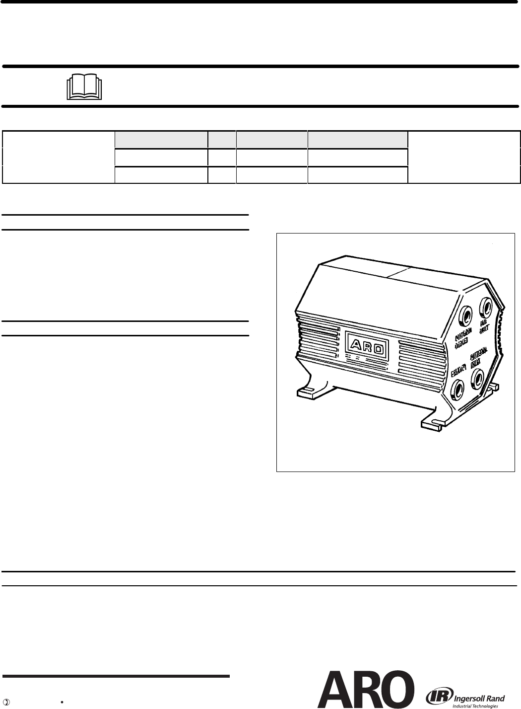
GENERAL
DESCRIPTION
THIS MANUAL COVERS THE FOLLOWING MODELS
MODEL TH'D CHECK TYPE WETTED MATERIAL
666023,J,H,L*-XXX NPT FLAT POLYPROPYLENE
666026,M,N,P*-XXX NPT FLAT GROUNDABLE ACETAL
* J,H,L,M,N,P Represent Inlet and Outlet Options, refer to page 3 for more information.
SERVICE KITS
Refer to Service Kit Chart on page 3 to match pump material with SerĆ
vice Kits offered. The ``X'' represents a variable digit of the Model No.
637273-XXX for Pump Rebuild. (Model digits 7,8,9)
637274-XX for Check Valve Replacement. (Model digits 7,9)
637275-XX for Diaphragm and Air Section repair. (Model digits 8,9)
637276 for Pre-assembled Replacement Air Valve Section. (Fig.2)
PUMP
DA
TA
MODELS - See Model Description Chart for ``-XXX'' on page 3.
PUMP TYPE -Non-Metallic Air Operated Double Diaphragm
MATERIAL - See Model Description Chart on page 3.
WEIGHT LBS. - Polypropylene 3.6 (1.63 kgs)
- Groundable Acetal 4.1 (1.86 kgs)
MAXIMUM AIR INLET PRESSURE - 100 p.s.i.g. (6.9 bar)
MINIMUM AIR INLET PRESSURE - 20 p.s.i.g. (1.4 bar)
MAXIMUM OUTLET PRESSURE - 100 p.s.i.g. (6.9 bar)
MAXIMUM FLOW RATE - 5 g.p.m. (18.9 Liters)
MAXIMUM SUCTION LIFT - 20 Ft. (Water)
MAXIMUM OUTPUT PER CYCLE -.014 Gallons (53 cc's)
MAXIMUM PARTICLE SIZE - 1/32" dia.
MAXIMUM TEMP. LIMITS -
Polypropylene 35_Fto120_F
Groundable Acetal 10_F to 150_F
GROUNDABLE - 666026-XXX Models Only
DIMENSIONAL DATA - See page 8.
NOISE LEVEL*- 59.8 db(A) @ 70 psi, 60 cycles per minute.
*The pump sound pressure levels published here have been updated to an Equivalent Continuous Sound Level (LAeq) to meet the intent of ANSI S1.13-1971, CAGI-PNEUROP S5.1 using four microphone locations.
The ARO Diaphragm Pump offers high volume delivery even at low air
pressures, easy self priming, the ability to pump various viscosity maĆ
terials and the ability to pass solids (as stated in the chart above). The
pump is designed to correspond to the needs of the user by offering a
variety of wetted parts configurations to handle almost any application.
Refer to the model and option chart on page 3.
Model 666026-XXX: The Acetal material used in this pump contains
Stainless Steel fibers, it's conductivity allows it to be connected to a
suitable ground, a ground screw is provided for this.
NOTICE: All possible options are shown in the chart on page 3 however
certain combinations may not be recommended, consult a representative
or the factory if you have questions concerning availability.
666023-XXX
1/4'' DIAPHRAGM PUMP
INGERSOLL RAND COMPANY LTD
209 NORTH MAIN STREET – BRYAN, OHIO 43506
(800) 495-0276 FAX(800) 892-6276 © 2010
www.ingersollrandproducts.com
OPERATING
AND SAFETY PRECAUTIONS
66602X-
X
PAGE 2 OF 8
ZRead and heed all Warnings, Cautions, and Safety PrecauĆ
tions before operating this pump.
ZUse only genuine ARO replacement parts to assure compatĆ
ible pressure rating and longest service life.
WARNING EXCESSIVE AIR PRESSURE. Can cause pump
damage, personal injury or property damage.
SDo not exceed the maximum inlet air pressure as stated on
the pump model plate.
WARNING STATIC SPARK. Can ignite flammable material
and vapors resulting in fire or explosion causing severe perĆ
sonal injury or property damage.
SThe pumping system and object being sprayed must be
grounded when it is pumping, flushing, recirculating or
spraying flammable materials such as paints, solvents,
lacquers, etc. or used in a location where surrounding atĆ
mosphere is conducive to spontaneous combustion.
S666026-XXX Groundable Acetal pumps: Use the pump
grounding screw provided. A screw terminal is provided
on the Fluid Cap (Remove the cover to gain access). ConĆ
nect a 12 ga. (min.) wire (66885-1 Kit is available) to a good
earth ground source.
SGround dispensing valve or device, containers, hoses
and any object to which material is being pumped.
SAfter grounding, periodically verify continuity of electrical
path to ground. Test with an ohmmeter from each compoĆ
nent (e.g.,hoses,pump,clamps,container,spray gun, etc.)
to ground to insure continuity. Ohmmeter should show 10
ohms or less.
SSecure pump, connections and all contact points to avoid
vibration and generation of contact or static spark.
SConsult local building codes and electrical codes for speĆ
cific grounding requirements.
WARNING
DIAPHRAGM RUPTURE. Can cause serious inĆ
jury or property damage. Material can be forced out of the air
exhaust muffler.
SPipe the exhaust to a safe remote location when pumping
hazardous or inflammable materials.
SUse a grounded 1/4" min. I.D. hose between the the pump
and the muffler.
WARNING
HAZARDOUS PRESSURE. Can result in serious
injury or property damage. Do not service or clean pump,
hoses or dispensing valve while the system is pressurized.
SDisconnect air supply line and relieve pressure from the
system by opening dispensing valve or device and/or
carefully and slowly loosening and removing outlet hose
or piping from pump.
WARNING HAZARDOUS MATERIALS. Can cause serious
injury or property damage. Do not attempt to return a pump to
the factory or service center that contains hazardous material.
Safe handling practices must comply with local and national
laws and safety code requirements.
SObtain Material Safety Data Sheets on all materials from
the supplier for proper handling instructions.
ZSAFETY PRECAUTIONS (GENERAL) should inĆ
clude:
SUse of static wire hoses.
SSubmersion of outlet hose end, dispensing valve or deĆ
vice within material being dispensed whenever possible.
(Avoid free streaming of material being dispensed.)
SProper ventilation of area away from heat, open flames
and sparks.
SKeeping inflammables away from heat, open flames and
sparks.
SKeeping containers closed when not in use.
SBe sure material hoses and other components are able to
withstand fluid pressures developed by this pump. Check
all hoses for damage or wear. Be certain dispensing deĆ
vice is clean and in proper working condition.
CAUTION Verify the chemical compatibility of the pump
wetted parts and the substance being pumped, flushed or reĆ
circulated. Chemical compatibility may change with temperaĆ
ture and concentration of the chemical(s) within the
substances being pumped, flushed or circulated. Consult
ARO Form No. 8677-P, Fluid Compatibility Guide, for informaĆ
tion on chemical compatibility.
CAUTION
Maximum temperatures are based on mechaniĆ
cal stress only. Certain chemicals will significantly reduce
maximum safe operating temperature. Consult Fluid CompatĆ
ibility Guide for chemical compatibility and temperature limĆ
its.
STemperature Limits:
Polypropylene 35_Fto120_F
Groundable Acetal 10_Fto150_F.
CAUTION
Be certain all operators of this equipment have
been trained for safe working practices, understand it's limitaĆ
tions, and wear safety goggles/equipment when required.
CAUTION
Do not use the pump for the structural support of
the piping system. Be certain the system components are
properly supported to prevent stress on the pump parts.
SSuction and discharge connections should be flexible
connections (such as hose), not rigid piped, and should
be compatible with the substance being pumped.
CAUTION Prevent unnecessary damage to the pump. Do
not allow pump to operate when out of material for long periĆ
ods of time.
SDisconnect air line from pump when system sits idle for
long periods of time.
WARNING
CAUTION
NOTICE
= Hazards or unsafe practices which could
result in severe personal injury, death or
substantial property damage.
= Hazards or unsafe practices which could
result in minor personal injury, product or
property damage.
= Important installation, operation or
maintenance information.
AIR
AND LUBE REQUIREMENTS
PAGE 3 OF 8
66602X-X
MODEL
DESCRIPTION CHART
WARNING EXCESSIVE AIR PRESSURE. Can cause pump
damage, personal injury or property damage.
SA filter capable of filtering out particles larger than 50 microns
should be used on the air supply. In most applications there is no
lubrication required other than the "O"ring lubricant which is apĆ
plied during assembly or repair.
SThe pump can be rotated 360_to suit the application. It may be
mounted upside down or on the wall with no effect on suction lift or
operating efficiency. The filter and regulator need to be oriented in
a normal vertical direction to function properly.
SPipe plugs included for the material inlets, they can be switched to
accommodate piping requirements however the fluid inlet must alĆ
ways be in the port closest to the mounting base.
SWhen lubricated air is necessary, supply the air lubricator with a
good grade of SAE 90 wt. non-detergent oil and set the lubricator
to a rate not to exceed one drop per minute.
INSTALLATION
SNOTICE: Re-torque fasteners prior to use. Refer to page step
#22 on page 7 for information.
SApply tape or pipe sealant to threads upon assembly to preĆ
vent leakage.
SSecure the diaphragm pump legs to a suitable surface to insure
against damage by vibration.
STo avoid problems install a particle fluid filter to screen out foreign
matter 1/32'' or larger in diameter.
SThe pump is not recommended for submerged applications.
SWhen the diaphragm pump is used in a forced-feed (flooded inlet)
situation it is recommended that a ``Check Valve'' be installed at the
air inlet.
OPERATING INSTRUCTIONS
SAlways flush the pump with a solvent compatible with the material
being pumped if the material being pumped is subject to ``setting
up" when not in use for a period of time.
SDisconnect the air supply from the pump if it is to be inactive for a
few hours.
FLUID
SThe outlet material volume is governed not only by the air supply
but also by the material supply available at the inlet. The materialĆ
supply tubing should not be too small or restrictive. Be sure not to
use hose which might collapse.
MAINTENANCE
Refer to the part list pg. 4 for Service Kit Information, parts view on
pg. 5. and Repair Proceedures on pgs 6 and 7.
SCertain ARO ``Smart Parts" are indicated which should be availĆ
able for fast repair and reduction of down time.
SProvide a clean work surface to protect sensitive internal moving
parts from contamination from dirt and foreign matter during serĆ
vice disassembly and reassembly.
SKeep good records of service activity and include pump in prevenĆ
tive maintenance program.
SER
VICE KITS
66602X- CHECK VALVE
DIAPHRAGM &
AIR SECTION REBUILD KIT
-344 637274-34 637275-44 637273-344
-34D 637274-3D 637275-4D 637273-34D
-34E 637274-3E 637275-4E 637273-34E
-644 637274-64 637275-44 637273-644
-64D 637274-6D 637275-4D 637273-64D
-64E 637274-6E 637275-4E 637273-64E
SVitonRand HytrelRare registered trademarks of the DuPont Company SKynarRis a registered trademark of Penwalt Corp SFluorazRis a registered trademark of Greene, Tweed & Co. Inc.
SSantoprene Ris a registered trademark of Monsanto Company, licensed to Advanced Elastomer Systems, L.P. SKey-LubeRis a registered trademark of Key Industries
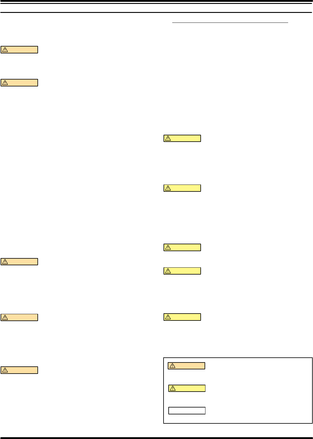
6660 X X
BODY MATERIAL,
INLET/OUTLET OPTION CHECK
MATERIAL DIAPHRAGM/O–RING
MATERIAL
43 POLYPROPYLENE
6 ACETAL
23 POLYPROPYLENE, (1)INLET/(1)OUTLET
26 GROUNDABLE ACETAL, (1)INLET/(1)OUTLET
2J POLYPROPYLENE, (1)INLET/(2)OUTLET
2H GROUNDABLE ACETAL, (1)INLET/(2)OUTLET
2L POLYPROPYLENE, (2)INLET/(1)OUTLET
2M GROUNDABLE ACETAL, (2)INLET/(1)OUTLET
2N POLYPROPYLENE, (2)INLET/(2)OUTLET
2P GROUNDABLE ACETAL, (2)INLET/(2)OUTLET
CHECK VALVE SEAT
MATERIAL
4.F.E
DR
E SANTOPRENER/FLUORAZ
– X X X FLUID SECTION MATERIAL OPTIONS
BASIC MODEL NO.
PTFE PTFE/T
PTFE/FLOURAZ
PTFE
MATERIAL
CODE
[A]=Aluminum
[B]=Buna ``N''
[D]=Acetal (Orange*)
[F]=Fluoraz
[G]=Groundable Acetal (Dk Gray)
[K]=Kraton
[N]=Neoprene
[P]=Polypropylene (Lt Gray)
[R]=Ryton
[S]=Steel
[SP]=Santoprene
[SS]=Stainless Steel
[U]=Polyurethane
*Refers to wetted parts only
`Manifold Qty's will be either
1 or 2 depending on the inlet/outlet
option selected. (Refer to to chart
on page 3.)
HThese parts are available in
Service Kits only, see the Service
Kit Chart at the top of the page and
on page 3.
PART NOTES
V``Smart Parts'' keep these items
on hand in addition to the Service
Kits for fast repair and reduction of
down time.
66602X-
X
PAGE 4 OF 8
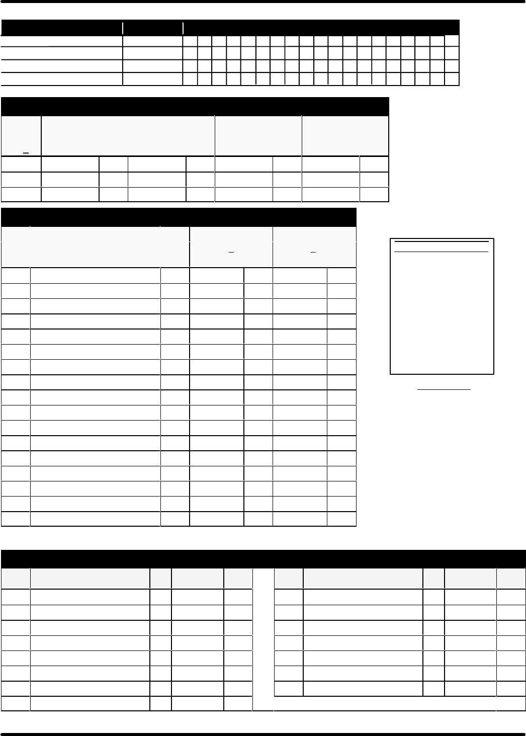
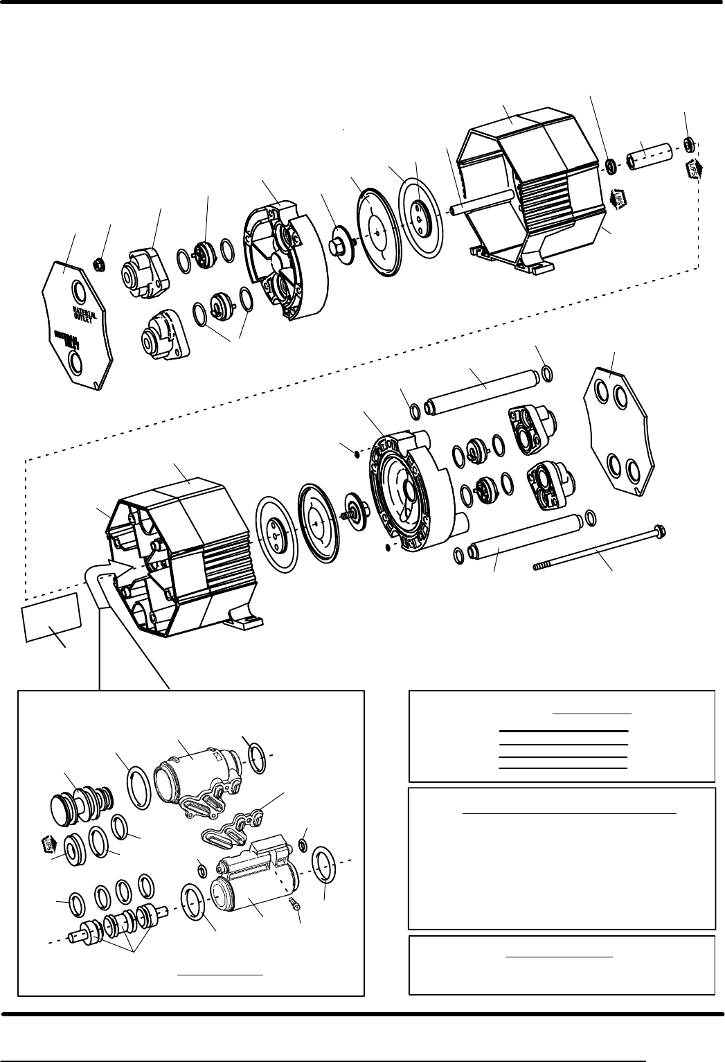
PARTS
LIST
DIAPHRAGM OPTIONS
``7" ``64" ``19" ``33"
66602X
-XXX
DIAPHRAGM
(2) [MTL]
``O"ring (2)
79mm X 4 mm [MTL]
``O"ring (8)
1-1/8" O.D. [MTL]
``O"ring (4)
3/4" O.D. [MTL]
-XX4 H93898 [T] H93947 [B] H93831 [T] H93830 [T]
-XXD H93898 [T] H93947 [B] H93933 [F] H93932 [F]
-XXE H93808 [SP] --- -- H93933 [F] H93932 [F]
COMMON PARTS
POLYPROPYLENE GROUNDABLE
666023,J,L,N 666026,H,M,P
ITEM DESCRIPTION (SIZE IN INCHES) QTY PART NO. [MTL] PART NO. [MTL]
j1 Rod (2-13/16 Long) (1) 93916 [S] 93916 [S]
j5 Washer (1-3/4 O.D.) (2) 93915 [SS] 93915 [SS]
j6 Diaphragm Nut (1/4-20) (2) 93810-1 [P] 93810-2 [D]
j16 Manifold (4) 93817-1 [P] 93817-2 [G]
j36 Manifold Tube (`) 93813-1 [P] 93813-2 [D]
37 Manifold Plug (`) 93941-1 [P] 93941-2 [D]
43 Ground Screw (10-32 x 1/4) Not Shown (1) ----- -- 93005 [S]
62 Nut (1/4-20) (6) 93828 [SS] 93828 [SS]
63 Pipe Plug (1/4-18) Not Shown (2) 93832-1 [P] 93832-2 [D]
j65 Fluid Cap, W/AIR INLET (1) 93812-1 [P] 93812-2 [G]
j66 Fluid Cap (1) 93811-1 [P] 93811-2 [G]
j68 Air Cap, Right (w / Groove d)(1) 93804 [P] 93804 [P]
j69 Air Cap, Left (w / Tongue Z)(1) 93805 [P] 93805 [P]
71 Check Asm.: Seat, Disc, Stop (4) H66973-1 [P] H66973-2 [D]
72 Cover, Right (1) 93816-2 [P] 93816-2 [P]
73 Cover, Left (1) 93816-1 [P] 93816-1 [P]
131 Bolt (1/4-20 x 6.250) (6) 93827 [SS] 93827 [SS]
AIR SECTION PARTS
ITEM DESCRIPTION (Size in Inches) QTY PART NO. [MTL] ITEM DESCRIPTION (Size In Inches) QTY PART NO. [MTL]
102 ``O''Ring (7/8 O.D.) (3) HY325-018 [B] 137 ``O''Ring (1 O.D.) (1) HY325-020 [B]
103 Bushing (1) 93917 [D] 138 ``O''Ring (13/16 O.D.) (1) HY325-114 [B]
110 ``U''Cup (13/16 O.D.) (1) HY186-54 [B] 142 Screw (#4-20) (3) 93942 [SS]
j111 Spool Asm.-(Incl'ds #110,#119,#138) (1) 65438 [D] 144 ``U''Cup (5/8 O.D.) (2) HY186-45 [B]
j118 Trip Rod Asm.- Inculdes (4) #119 (1) 65439 [D] j145 Minor Valve Block (1) 93807 [R]
119 ``O''Ring (5/8 O.D.) (1) H15066 [B] 146 ``O''Ring (5/16 O.D.) (2) HY325-008 [B]
132 Gasket (1) H93809 [K] 147 ``O''Ring (7/16 O.D.) (2) HY325-011 [B]
j135 Valve Block (1) 93806 [R]
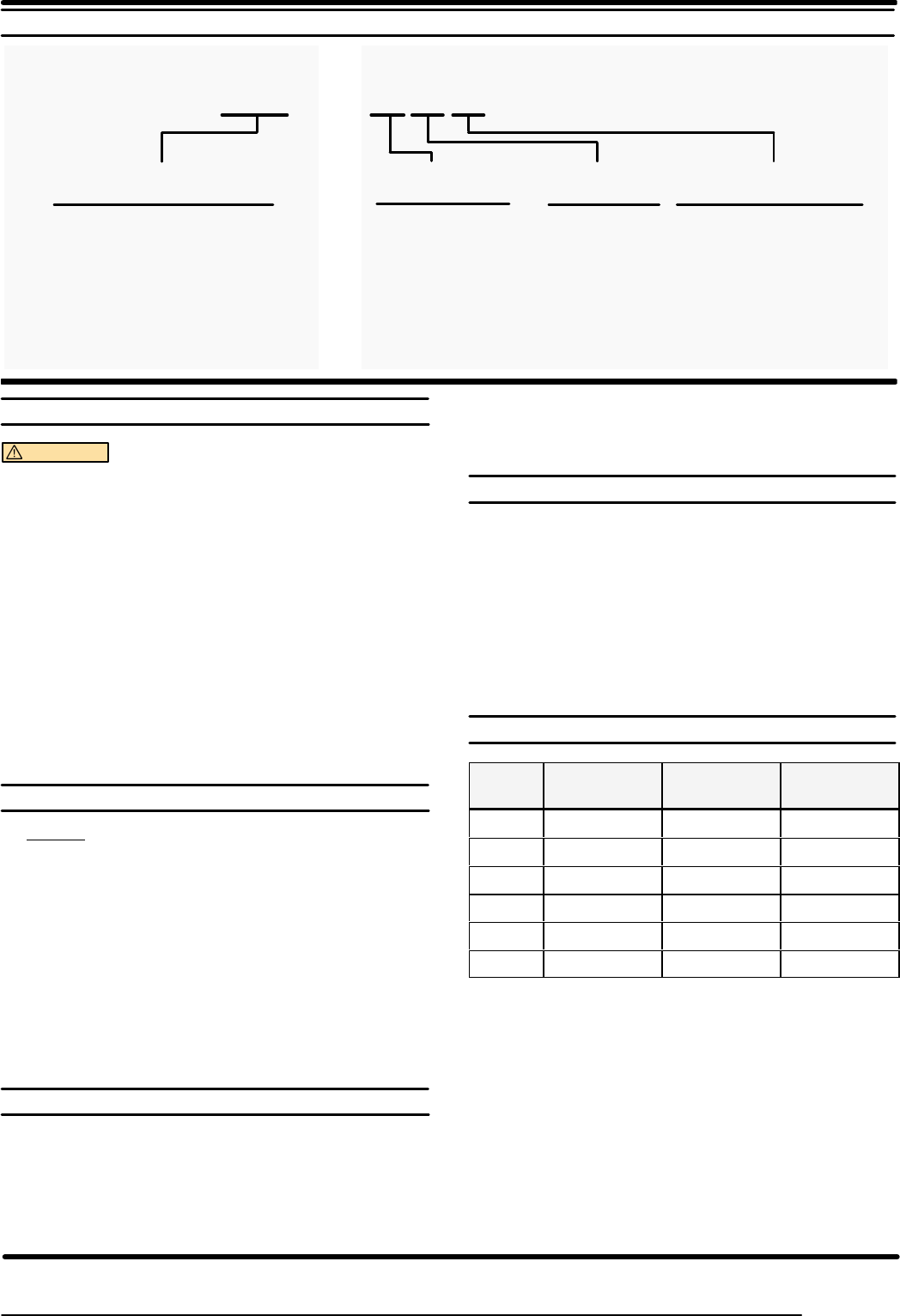
SERVICE KITS
637273-XXX
637274-XX
637275-XX
7 19 33 64 71 102 110 119 137 138 144 146 147
7193364
71
102 119 137 138 144 146 147
19 33
CHECK VALVE KIT
COMPLETE REBUILD KIT
DIAPHRAGM & AIR VALVE KIT
THESE ITEMS ARE INCLUDED IN THE KITSKIT NUMBER
Keylube packet
93706-1 is
included
with all kits.
110
637276 102 137 146 147
AIR VALVE REPLACEMENT ASM.
Refer to the Kit Selection Chart page 3 for proper ``-XXX" for your model.
145135111 118
132
132
132 142
[T]= PTFE
111
137
102
119
118
138
145
102
135
119
102
146
146
110
AIR
V
ALVE
(SHOWN
2X SCALE)
FIGURE 2
LUBRICATION
Apply Keylube (93706-1) to all
``O"rings, ``U''Cups & mating parts
.TORQUE REQUIREMENTS ,
NOTE: DO NOT OVERTIGHTEN FASTENERS
147
68
33
72
``B''
65
FIGURE 1
33
62 ,
64
7
103
144
69
71
16
19
5,
73
144
1
66
PARTS
LIST
131 ,
Logo
Plate
6,
These parts are included in Air Valve Replacement Kit 637276.
``A''
MANIFOLD TUBE
INLET /
OUTLET
OPTIONS
SI/SO
SI/DO
DI/SO
DI/DO
``A''
36
36
37
37
``B''
36
37
36
37
132
142,
(142) Torque to 4-6 in.lbs.
(62) / (131) Manifold bolts / nuts 35-45 in.lbs.,
tighten together alternately & evenly, then re-torque.
(6) / (5) Diaphragm nut / washer 75-85 in.lbs.
use Loctite #242, tighten together.
d
Z
PAGE 5 OF 8
66602X-X

66602X-
X
PAGE 6 OF 8
PUMP
DISASSEMBL
Y AND REASSEMBL
Y
GENERAL PUMP REPAIR NOTES:
STools needed to complete disassembly and repair.:
S7/16" Wrench, 9/16" Wrench,7/16" Socket, 9/16" Socket,
Spanner Wrench, Torque Wrench (measuring inch pounds),
``O"ring Pick.
SOnce the pump is disassembled, you have the opportunity to clean
and inspect all parts for wear. Look for deep scratches on metallic
surfaces, and nicks or cuts in ``O"rings. Replace old parts with new
ones as necessary.
STake precautions to prevent cutting ``O"rings upon installation.
SLubricate ``O"rings and ``U''cups with Key-lube or equivalent. A
packet of this lubricant is included in each Service Kit.
SDo not over-tighten fasteners, refer to torque specification block
on view.
SRe-torque fasteners following restart.
Service Kits available. From your local distributor.
(Kits also include Keylube grease packet.)
SSERVICE KIT: 637273-XXX contains parts for a complete pump
rebuild.
SSERVICE KIT: 637274-XX contains new check assemblies.
SSERVICE KIT: 637275-XX includes parts to rebuild the air motor
and diaphragms.
SAIR VALVE REPLACEMENT KIT: 637276 includes a complete
factory pre-assembled replacement air valve section.
PUMP DISASSEMBLY:
1. Place the pump on a flat workbench. Remove both cover plates
and set them aside.
2. Using a 7/16-inch wrench, loosen the bolts that run through the
pump and remove the six nuts. Pull the bolts through the pump
body and set them aside.
3. The fluid caps and manifolds may fall free at this time. If not, grasp
the fluid caps and separate them from the pump body.
4. The air inlet fluid cap has two small ``O"rings at the air inlet and exĆ
haust ports. Remove these with the ``O"ring pick.
5. The manifold tubes may have pulled free of the pump when the
fluid caps were removed, if not remove both tubes from the pump
body.
6. Remove the ``O"rings from the ends of each manifold tube.
7. If the manifolds did not fall free, separate them from the fluid caps
at this time.
8. To remove the checks, it may be necessary to push a dowel
through the fluid caps.
9. Use the pick to remove any ``O"rings that remain in the manifold or
fluid cap.
10. With the 9/16" socket and 9/16" wrench, loosen and remove either
diaphragm nut. Gently pull the diaphragm away from the pump
body.
NOTE: Models with diaphragms will have back up ``O"rings.
11. Push the connecting rod through the pump body. Wrap the conĆ
necting rod in a shop rag and secure in a soft-jawed vise.
12. Remove the remaining diaphragm nut with a 9/16-inch wrench.
NOTE: Be careful not to mar the connecting rod surface during this
step.
13. Using the 9/16" wrench and the spanner wrench, remove the backĆ
up washer from the diaphragm nut. This will allow you to separate
the diaphragm from the nut.
NOTE: Be careful not to round the diaphragm nut during this step.
14. Pull apart the two air caps. The connecting rod bushing will fall free.
If the air valve block asm. did not fall free, pull it from the air cap at
this time.
15. Use the ``O"ring pick to remove the air cap seal.
16. Use the pick to remove the U-cups and any ``O"rings that may reĆ
main in the air caps.
17. Remove the retaining screws and separate the valve block and miĆ
nor valve block. Pull the piston from the minor valve block. Then
remove all ``O"rings using the pick. Gently push the spool from the
valve block. A dowel may be needed to push out the spool.
NOTE: Be careful not to damage either part during this step.
18. Use the pick to remove all ``O"rings from the spool and the center
gasket from the valve block.
PUMP REBUILD PROCEDURES: (rebuild by service kits)
For the 637273-XXX and 637275-XX Service Kits
AIR VALVE SECTION (Steps 1-6)
1. Install new ``O"rings and U-cup on the spool and piston.
2. Lubricate the spool, piston and internal bores of the valve blocks.
3. Insert the piston into the minor valve block, being careful not to
damage any ``O"rings during this process. Now slide the spool into
the valve block, inserting the small end first.
NOTE: There may be some resistance when installing the piston
and spool, however you should not have to force the parts into
place.
4. Install the shaped gasket into the minor valve block and push the
major valve block into the minor valve block, retain with screws and
torque to 6 in.lbs.
NOTE: Do not lubricate the gasket or valve block surfaces.
5. Insert new, lubricated ``U''cups in each of the air caps. The lips of
the ``U''cups should face towards the diaphragm chambers. Install
the air cap seal.
6. Pre-assemble each of the two diaphragms by first inserting the diĆ
aphragm nut through the new diaphragms, Appy Loctite #242 to
the threads, attach the backup washer, secure with the a 9/16"
wrench and spanner wrench. Using a torque wrench, tighten the
diaphragm nut and washer to 80-inch pounds.
NOTE: Be careful not to round off the diaphragm nut. Backup
``O"rings are included in the Service Kit for models with diaĆ
phragms.
For the 637274-X and 637273-XXX Service Kits:
7. Install new, lubricated ``O"rings onto the four complete check asĆ
semblies that are included with the Service Kit. Also put new
``O"rings on each end of the two manifold tubes.
PUMP REASSEMBLY:
8. First hand tighten the connecting rod to one of the diaphragm asĆ
semblies.
9. Place the air cap on end. Insert the air valve assembly and bushing
in place. (be sure the U-cups are installed). Align logo plates and
push the air caps together.
NOTE: Be sure the bushing, and air valve assembly remain in
place.
10. Lubricate the connecting rod and insert it into the air cap.
NOTE: Models with diaphragms have backup ``O''rings that
are placed in the groove of each air cap.
PTFE
PTFE
PTFE

PAGE 7 OF 8
66602X-X
REASSEMBLY (CONT’D)
11. Attach the second diaphragm assembly to the connecting rod,
hand tighten the (pre-assembled) diaphragm nut and washer until
it bottoms out on the connecting rod.
NOTE: Models with Teflon diaphragms have backup ``O"rings that
are placed in the groove of each air cap. Do not over-tighten the
nut.
12. Replace the ``O"rings at the air inlet and exhaust ports of the air inĆ
let fluid cap.
13. Properly align the fluid cap and attach it to the pump body. When in
place, the air inlet should be at the upper right, with the exhaust at
the lower left.
14. Insert a bolt into the bore just below the air inlet and one just above
the exhaust port. Applying a small amount of anti-seize compound
or lubricant to the threads will help prevent the nut from binding.
Properly align the second fluid cap and push it into position.
15. Secure the fluid caps by installing nuts onto each bolts, but do not
tighten fully at this time.
16. Insert the manifold tubes through the pump body, being careful that
the ``O"rings do not fall off during this step.
17. Press two of the check assemblies into the lower inlet ports of the
fluid caps. The checks are keyed and can be assembled only one
way.
NOTE: If the old checks are to be used, clean all parts in an apĆ
propriate solvent.
18. Place manifolds over each check, pushing firmly to secure the
check and the manifold tube.
19. Press the remaining checks into the upper, outlet ports of the fluid
caps. Make sure the smaller seat opening is inserted first.
20. Place manifolds over each check, pushing firmly to secure the
check and the manifold tube.
21. Insert two bolts through each manifold. Secure by attaching a nut
to each bolt. Applying a small amount of anti-seize compound or
lubricant to the threads will help prevent the nut from binding.
22. Tightening sequence for the long bolts:
IMPORTANT ASSEMBLY NOTE: The fastener nuts have ribs
which lock into the material, for best results place a socket wrench
on the nuts so they are held stationary and tighten only the bolts
they are used with.
.Torque all six bolts to 40-inch pounds.
.Cross tighten the bolts in an alternating star shaped
pattern.
.Repeat torque sequence twice.
23. Finish reassembly by pressing both cover plates into place.
TROUBLE SHOOTING
Air Motor stalls
SCheck for blown Diaphragm
SCheck for damaged ``O"rings on the Spool.
SCheck for damaged ``O"rings on the Trip Rod.
SCheck valve block gasket for leakage.
Air leaks from Exhaust
SCheck for damaged ``O"rings on the Valve Block and Minor Valve
Block, Spool or Trip Rod.
SCheck gasket between valve blocks for leakage.
SU-cups on Connecting Rod Bushing are damaged or installed
backwards.
Fluid leaks from Exhaust
SCheck for diaphragm damage.
SCheck for diaphragm screws not adequately torqued.
Low flow, or pump continues to cycle after shut-off.
SCheck for trapped air if the pump is oriented where the inlet check
is above the outlet check. Temporarily increase the flow or re-
prime the pump.
SCheck for damaged seats or foreign matter clogging the check asĆ
sembly.
Air leaks from pump (other than exhaust)
SCheck for bolts not evenly or adequately torqued.
SCheck for ``O"ring missing/damage between the fluid cap and the
air cap on the air inlet side.
External fluid leaks from pump.
SCheck for bolts not properly torqued.
SCheck for damaged ``O"rings on the Manifold Tube.
SCheck for damaged ``O"rings on the Valve Check.
SCheck for damaged diaphragm seal.
Pump operates but dispenses little or no fluid
SCheck for obstruction in fluid line.
SCheck for foreign matter clogging check assemblies.
Note: Install a fluid screen on the material inlet hose if the problem
continues.
SSuction line too small.
SCheck for air leakage at the air/fluid inlet pipe plugs. Use
tape or pipe sealant upon assembly.
PTFE
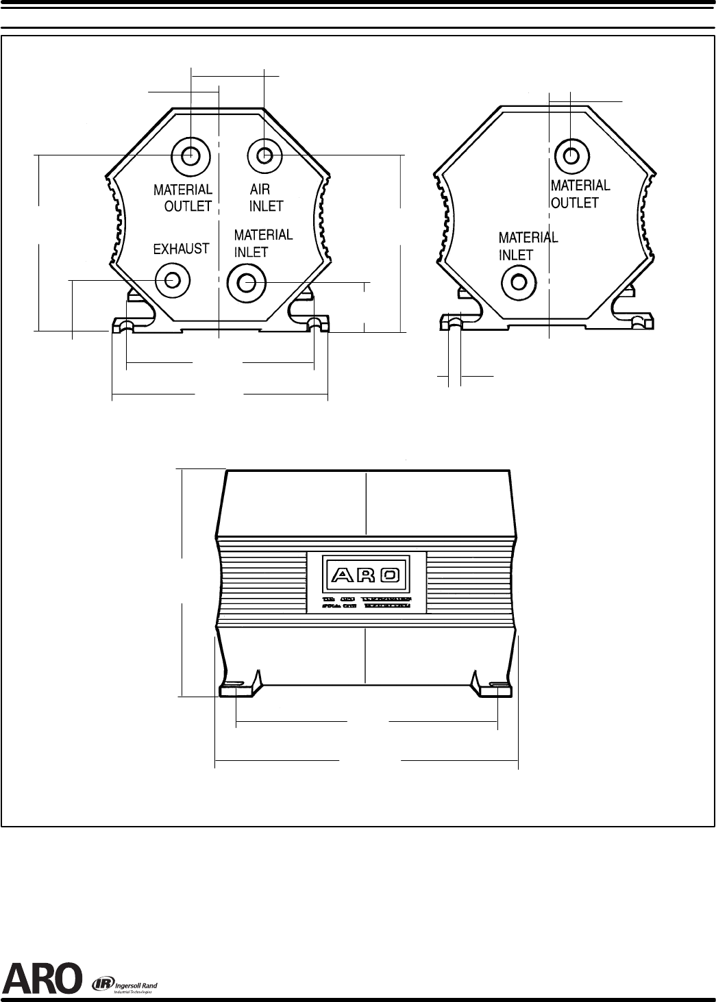
Dimensions shown are for reference only, they are shown in inches and millimeters (mm).
5-5/8
(142 mm)
6-1/2
(165 mm)
7-3/8
(188 mm)
5-1/2
(140 mm)
4-3/4
(121 mm)
4-3/8
(113 mm)
4-1/2
(114 mm)
1-3/8
(35 mm)
11/16
(18 mm)
1-1/4
(32 mm)
5/16 SLOT
(8 mm)
11/16
(18 mm)
SIDE VIEW
END VIEWS
1-13/16
(46 mm)
DIMENSIONAL
DA
TA
PN 97999-571
66602X-
X
PAGE 8 OF 8
