ip access IPA217C 8 user 3G Access Point operating at UMTS Band 4 User Manual N3G INST 300 AP Install v7 0
ip.access ltd 8 user 3G Access Point operating at UMTS Band 4 N3G INST 300 AP Install v7 0
User manual

nano3G AP Installation Manual
N3G_INST_300 7.0 ip.access Ltd
Building 2020
Cambourne Business Park
Cambourne
Cambridgeshire CB23 6DW
United Kingdom
www.ipaccess.com

Revision History
Version Change Summary Date Author
1.0 Released for N3G_1.1 29 Jul 2009 ZN1
2.0 Released for N3G_1.1_UPGRADE 28 Aug 2009 ZN1
3.0 Released for N3G_1.1_UPGRADE MR1 11 Sep 2009 ZN1
3.1 Minor corrections 08 Dec 2009 ZN1
3.2 Expanded hardware installation, other editorial changes 23 Feb 2010 AM4
3.3 Updated from review feedback 01 Mar 2010 AM4
4.0 Released for N3G_1.1_UPGRADE MR10 05 Mar 2010 AM4
4.1 Updated from review feedback 26 Mar 2010 AM4
4.2 Minor updates from review feedback 30 Mar 2010 AM4
5.0 Released for N3G_1.1_UPGRADE MR10.1, with approval comments 01 Apr 2010 AM4
6.0 Re-released for N3G_1.1_UPGRADE MR10.1 with minor correction 12 Apr 2010 AM4
6.1 Updated for N3G_2.0, added nano3G E8 information 13 Apr 2010 ZN1
6.2 Editorial changes 15 Apr 2010 AM4
6.3 Updated from review comments, reorganised so config file creation is all
in one section
14 Jun 2010 AM4
7.0 Released, incorporating minor comments from approval 24 Jun 2010 AM4
The information contained in this document is commercially confidential and must not be
disclosed to third parties without prior consent.

nano3G AP Installation Manual Contents
N3G_INST_300 v6.3 for N3G_2.0 © ip.access Limited 2010 Page i
Table of Contents
1 Introduction............................................................................................ 1
1.1 Overview ............................................................................................................ 1
1.2 User Requirements ............................................................................................ 1
1.3 Related Information............................................................................................ 1
1.4 Licenses and Copyright Notices ........................................................................ 2
1.5 Terminology ....................................................................................................... 2
2 Installation Requirements..................................................................... 3
2.1 Installation Overview.......................................................................................... 3
2.1.1 Overview of Installation with On-Site Commissioning .......................................... 3
2.1.2 Overview of Installation with Pre-Commissioned nano3G AP.............................. 3
2.1.3 Overview of Installation with Pre-Configured nano3G AP.................................... 4
2.2 Requirements for All nano3G AP....................................................................... 5
2.2.1 General Site Requirements .................................................................................. 5
2.2.2 Information Required for Commissioning ............................................................. 6
2.2.3 Information Required for Configuration from the OMC-R..................................... 7
2.3 nano3G S4 AP Site Requirements .................................................................... 8
2.3.1 Power ................................................................................................................... 8
2.3.2 Physical .............................................................................................................. 10
2.3.3 IP Bandwidth Requirements............................................................................... 10
2.3.4 Sundry Installation Equipment............................................................................ 10
2.4 nano3G E8 AP Site Requirements .................................................................. 11
2.4.1 Power ................................................................................................................. 11
2.4.2 Physical .............................................................................................................. 12
2.4.3 IP Bandwidth Requirements............................................................................... 13
2.4.4 Installation Tool Requirements........................................................................... 13
3 nano3G AP Hardware Installation ...................................................... 14
3.1 Warnings and Regulatory Information ............................................................. 14
3.2 Hardware Installation - nano3G S4 AP ............................................................ 14
3.2.1 Unpack the nano3G S4 AP ................................................................................ 14
3.2.2 Commission the nano3G S4 AP......................................................................... 15
3.2.3 Cable Connections ............................................................................................. 15
3.2.4 Mount the nano3G S4 AP .................................................................................. 16
3.3 Hardware Installation - nano3G E8 AP ............................................................ 20
3.3.1 Unpack the nano3G E8 AP ................................................................................ 20
3.3.2 Removable Cable and Antenna Covers ............................................................. 20
3.3.3 Antennas ............................................................................................................ 21
3.3.4 Commission the nano3G E8 AP......................................................................... 22
3.3.5 Cable Connections ............................................................................................. 22
3.3.6 Mount the nano3G E8 AP on a Wall .................................................................. 23
4 Commission a nano3G AP.................................................................. 27
4.1 Configure a Provisioning Laptop to Connect to the AP.................................... 27

nano3G AP Installation Manual Contents
N3G_INST_300 v6.3 for N3G_2.0 © ip.access Limited 2010 Page ii
4.2 Configure the AP-AC Connection .................................................................... 28
4.2.1 Static IP Configuration........................................................................................ 29
4.2.2 Configure the AC Connection............................................................................. 29
5 Configuration File Preparation ........................................................... 31
5.1 Overview of Attribute Configuration Files......................................................... 31
5.1.1 Attribute Types and Values ................................................................................ 32
5.2 Create a nano3G AP Attribute Configuration File............................................ 33
5.3 Example AP Configuration Files ...................................................................... 34
5.3.1 Example Generic Template File for nano3G S4 AP........................................... 34
5.3.2 Example AP-Specific Configuration File............................................................. 35
5.3.3 Other Attributes .................................................................................................. 36
6 Configuring a nano3G AP from the OMC-R ...................................... 38
6.1 Check and Upgrade the nano3G AP Software Image ..................................... 38
6.1.1 Check the Current Software Image Version....................................................... 38
6.1.2 Download the Latest Software Image from the OAM File Server to the AP....... 38
6.2 Apply an Attribute Configuration to the AP ...................................................... 39
6.3 Finalize Configuration ...................................................................................... 40
6.3.1 Final Attribute Changes and Checks.................................................................. 40
6.3.2 Network Listen and Frequency Correction ......................................................... 40
6.3.3 Automatic Configuration Backup ........................................................................ 40
6.4 Bring the AP into Service ................................................................................. 40
7 Troubleshooting .................................................................................. 41
7.1 LED Status Indicators ...................................................................................... 41
7.1.1 nano3G S4 AP LEDs.......................................................................................... 41
7.1.2 nano3G E8 AP LEDs.......................................................................................... 42
7.2 Backhaul Network Connection Problems......................................................... 43
7.3 Factory Reset................................................................................................... 43
7.3.1 nano3G S4 AP Factory Reset ............................................................................ 43
7.3.2 nano3G E8 AP Factory Reset ............................................................................ 44
7.4 nano3G E8 AP Does Not Start Up................................................................... 44
8 nano3G AP and PSU Regulatory Information ................................... 45
8.1 Warnings and Cautions.................................................................................... 45
8.2 Regulatory Statements for nano3G S4 AP ...................................................... 47
8.2.1 Type Approval and EMC Standards................................................................... 47
8.2.2 Safety Standards................................................................................................ 47
8.3 Regulatory Statements for nano3G E8 AP ...................................................... 48
8.3.1 Type Approval and EMC Standards................................................................... 48
8.3.2 Safety Standards................................................................................................ 48

nano3G AP Installation Manual Introduction
N3G_INST_300 v6.3 for N3G_2.0 © ip.access Limited 2010 Page 1
1 Introduction
The ip.access nano3G AP is an indoor Access Point for enterprise applications.
This manual provides all the necessary information required to install an ip.access nano3G
AP. The manual provides step-by-step instructions for hardware installation and
configuration steps required to bring a nano3G AP into service.
The AP can be configured with a static IP address or it can obtain an IP address
dynamically via DHCP. The AP-AC connection can be configured to be secure (via IPSec
and a security gateway) or unsecured.
1.1 Overview
This manual is organised as follows:
• AP installation requirements
• AP configuration preparation
• AP hardware installation
• Commissioning configuration, for initial connection to an AC
• Configuration from the OMC-R
• Installation troubleshooting
• Regulatory warnings and safety information
• Supplementary information on licensing
1.2 User Requirements
It is assumed that any readers that will use the OMC-R Client already know how to:
• Start the OMC-R Client
• Navigate the Explorer Pane to find an AP object
Refer to [OPM_410] for information on using the OMC-R Client.
1.3 Related Information
[INST_430] 3G OAM File Server Installation Manual (N3G_INST_430)
[OPM_300] nano3G AP Operations Manual (N3G_OPM_300)
[OPM_410] 3G OMC-R Client Operations Manual (N3G_OPM_410)
[OPM_430] nano3G OAM File Server Operations Manual (N3G_OPM_430)
[REF_105] nano3G System Glossary (N3G_REF_105)
[REF_110] nano3G System Configuration Management (CM) MIB Reference Manual
(N3G_REF_110)
[REF_300] nano3G AP License and Copyright Reference (N3G_REF_300)
[21.905] Vocabulary for 3GPP Specifications (3GPP 3G TR 21.905)

nano3G AP Installation Manual Introduction
N3G_INST_300 v6.3 for N3G_2.0 © ip.access Limited 2010 Page 2
1.4 Licenses and Copyright Notices
Portions of the AP are constructed from third-party software and open source code and
ip.access ltd gratefully acknowledges the contributions that these libraries, technologies
and components have made to the product. Each of these is supplied under the terms of a
license agreement and these are either reproduced or referenced in [REF_300], in line with
the stipulations of their authors.
1.5 Terminology
Common nano3G System terminology is defined in [REF_105].
For additional 3G terminology, see [21.905].

nano3G AP Installation Manual Installation Requirements
N3G_INST_300 v6.3 for N3G_2.0 © ip.access Limited 2010 Page 3
2 Installation Requirements
2.1 Installation Overview
The are three basic strategies for installing and commissioning a nano3G AP:
• Take a nano3G AP on site that is in the default factory state, install and
commission the AP on site then configure it remotely from the OMC-R and enable
it for service
• Take a previously commissioned nano3G AP on site and perform the physical
installation only, then configure it remotely from the OMC-R and enable it for
service
• Take a fully configured nano3G AP on site and perform the physical installation
only
In all cases, once the AP is up and running, perform some basic tests to verify the AP can
provide service. Also, after the AP has been running for 24 hours, use Network Listen to
check the frequency offset from a macro neighbour, if any are available, and then apply a
frequency correction if required.
2.1.1 Overview of Installation with On-Site Commissioning
The principal activities for this are:
1) Unpack the nano3G AP hardware on site, verify it is undamaged and power it up.
This is done by the installation engineer, as described in section 3.
2) Commission the nano3G AP for connecting to its serving AC. This is done by the
installation engineer, using a commissioning laptop, as described in section 4.
3) Install the nano3G AP hardware in the required location, with power and its
backhaul connection. This is done by the installation engineer, as described in
section 3. The AP should now connect to its serving AC and be accessible in the
OMC-R.
4) Use the OMC-R to upgrade the AP software and configure the AP, then bring the
AP into service. This is described in section 6. Typically this is done remotely by an
OAM engineer from the NOC, but could also be done by the on-site installation
engineer, assuming it is possible to make a connection to the OMC-R from the
provisioning laptop.
The benefits of this method are:
• Any nano3G AP in the default factory state can be taken on site.
• By corollary, if the nano3G AP is damaged or faulty, it can be replaced immediately
by a spare.
2.1.2 Overview of Installation with Pre-Commissioned nano3G AP
The principal activities for installing and commissioning any nano3G AP are:
1) Commission the nano3G AP, as described in section 4, before the on-site visit.
2) Once on site, unpack the nano3G AP hardware and verify it is undamaged. This is
done by the installation engineer, as described in section 3.

nano3G AP Installation Manual Installation Requirements
N3G_INST_300 v6.3 for N3G_2.0 © ip.access Limited 2010 Page 4
3) Install the nano3G AP hardware in the required location, with power and its
backhaul connection. This is done by the installation engineer, as described in
section 3. The AP should now connect to its serving AC and be accessible in the
OMC-R.
4) Use the OMC-R to upgrade the AP software and configure the AP, then bring the
AP into service. This is typically done remotely by an OAM engineer from the NOC,
as described in section 6.
The benefits of this method are:
• The site installation engineer does not need a commissioning laptop.
• By corollary, the site installation engineer does not need to know the user name
and password for the AP commissioning web page.
• The nano3G AP is effectively plug-and-play, apart from requiring updates/
configuration from the OMC-R.
The disadvantages of this method are:
• The Cell ID is part of the commissioning data, which means that each AP is
destined for a specific location. If the nano3G AP is faulty, it is likely to take longer
to deploy a replacement AP with the same Cell ID than it would for on-site AP
commissioning.
2.1.3 Overview of Installation with Pre-Configured nano3G AP
The principal activities for installing and commissioning any nano3G AP are:
1) Commission the nano3G AP, as described in section 4, before the on-site visit.
2) In addition, ensure the nano3G AP has the correct software, is fully configured and
enabled to provide service, before the on-site visit.
3) Once on site, unpack the nano3G AP hardware and verify it is undamaged. This is
done by the installation engineer, as described in section 3.
4) Install the nano3G AP hardware in the required location, with power and its
backhaul connection. This is done by the installation engineer, as described in
section 3. The AP should now connect to its serving AC and start providing service
immediately. It will also be accessible in the OMC-R.
5) If the AP is not already configured, commission the AP for connecting to its serving
AC, which will also make the AP accessible from the OMC-R (installation engineer
on site, see section 4).
6) The installation engineer can immediately make test calls with the nano3G AP.
Optionally also use Network Listen to verify the pre-configured neighbour list is
optimal, or collect information about neighbour cells that can be used to populate
the neighbour list.
The benefits of this method are:
• The site installation engineer does not need a commissioning laptop.
• By corollary, the site installation engineer does not need to know the user name
and password for the AP commissioning web page.
• The nano3G AP is effectively plug-and-play.
• If the nano3G AP has also been enabled for service prior to the site visit, the
installation engineer can make test calls immediately.

nano3G AP Installation Manual Installation Requirements
N3G_INST_300 v6.3 for N3G_2.0 © ip.access Limited 2010 Page 5
The disadvantages of this method are:
• If the nano3G AP is faulty due to damage in transit or some other failure, it may
take time to deploy a replacement AP with the same configuration.
2.2 Requirements for All nano3G AP
This applies to all nano3G APs.
2.2.1 General Site Requirements
All nano3G AP models have the following general requirements for on-site installation:
• If the AP will be commissioned on site, a provisioning/commissioning laptop with:
• OS: Windows XP
• Web browser: Microsoft Internet Explorer 7
• JavaScript enabled in the web browser
• Optionally, a short Ethernet cable for connecting the provisioning laptop to the AP
• A temporary means to provide power to the AP while it is connected to the
provisioning laptop
• A permanent means to provide power to the AP once it is connected to the
backhaul
• An Ethernet connection to the backhaul via CAT5 Ethernet cabling
• Access to a DNS service on the backhaul to resolve symbolic addresses
• Access to an NTP service on the backhaul to set the correct time and date
• If a firewall is in place on the network an AP will use for backhaul, this must be
configured to allow traffic to and from the AP. See the port usage section below.
Port Usage
All connections are outgoing. That is, they are initiated from the AP. Port usage has some
dependency on whether or not the AP is using IPsec.
With IPSec, the standard two ports are used:
Without IPSec, the following ports are used:
Protocol Destination Port Use
udp 500 IPSec initial connection
udp 4500 IPSec operations
Protocol Destination Port Use
tcp 3052 SOIP connection to AC
udp 3000 CS RTP to AC
udp 3001 CS RTCP to AC
udp 3002 CS Mux to AC
udp 5000 PS RTP to AC
udp 5001 PS RTCP to AC

nano3G AP Installation Manual Installation Requirements
N3G_INST_300 v6.3 for N3G_2.0 © ip.access Limited 2010 Page 6
The following ports are also used. When IPsec is used, they may be inside or outside the
IPSec tunnel, depending on configuration:
2.2.2 Information Required for Commissioning
All nano3G AP models require the configuration details listed in this section. This
information will typically be used on-site to commission an AP from the provisioning laptop,
so that the AP can subsequently connect to its serving AC.
Note: It is possible to commission an AP before taking it on site. However, this means that the Cell
ID for the AP must be known and correctly configured before it is taken on site, as the Cell
ID is one of the initial commissioning parameters.
For connecting to the AP from the provisioning laptop:
• User name and password for the AP web server - contact customer support at
ip.access for the current user name and password
For commissioning the AP:
• IP Address or FQDN of the serving nano3G AC
• Cell ID (also used as the ID of this AP on the serving nano3G AC)
• IP Address or FQDN of an NTP server
• DHCP or static IP
• If static IP is required:
• IP address for the AP
•Netmask
• IP Address or FQDN of the default gateway
• IP Address or FQDN of the Primary DNS
• IPSec is optional, but if IPSec is required:
• IP Address or FQDN of the IPsec Security Gateway
• IP Address or FQDN of a CRL server
udp 5002 PS Mux to AC
Protocol Destination Port Use
tcp 80 PM upload, software download, CRL download
tcp 443 PM upload, software download, CRL download
udp 53 DNS
udp 67 DHCP - not needed for static IP configuration
udp 68 DHCP - not needed for static IP configuration
udp 123 NTP
Protocol Destination Port Use

nano3G AP Installation Manual Installation Requirements
N3G_INST_300 v6.3 for N3G_2.0 © ip.access Limited 2010 Page 7
• Optionally, Traffic Selector information (IP address and subnet mask)
A traffic selector defines a range of IP addresses that are sent through the
IPSec tunnel. This allows an extra degree of control over the traffic that is
passed down the IPSec tunnel. Normally, the security gateway controls this
range and no other configuration is needed.
2.2.3 Information Required for Configuration from the OMC-R
All nano3G AP models require the configuration details listed in this section. This
information will be used to configure an AP from the OMC-R Client, typically by a NOC
engineer.
• User name and password for the OMC-R Client. To be able to configure an AP
from the OMC-R Client, the user name must have Full Access to the AC serving
the AP and Full Access granted to its APs. See [OPM_410] for full details about
user permissions.
• The URL to the latest AP software image on the OAM File Server.
• If available, the location of the configuration file(s) that has been pre-provisioned
with the attribute settings for the AP. This will be used to rapidly configure the AP
via the OMC-R Load Attributes Wizard. As a minimum, it is recommended to
create a generic configuration file that contains attribute settings that are common
to all APs in the network. Optionally create a separate attributes file for each AP to
be commissioned (see section 5).
• The minimum set of configuration data for the AP is:
• MCC
•MNC
•LAC
•RAC
•SAI SAC
•SAI LAC
•UARFCN
• Scrambling code
• RNC ID
• RSSI scan bands
• Latitude and longitude of the APs installation site, for RANAP location
reporting
• Additional configuration that may be required includes:
• Static neighbour list - see [OPM_300] for neighbour list configuration
• URLs for the PM reporting and diagnostic services on the OAM File Server
Note: It is possible to configure an AP before taking it on site.
nano3G AP Installation Manual Installation Requirements
N3G_INST_300 v6.3 for N3G_2.0 © ip.access Limited 2010 Page 8
2.3 nano3G S4 AP Site Requirements
The nano3G S4 APs are typically installed in retail or small office environments. In
summary, each AP will require:
• Power supplied in one of the following ways:
• From the mains adaptor unit supplied with the AP, which requires a suitable
mains power supply point near the AP that is within reach of the adaptor’s
cabling
or
• From the supplied POE splitter, which requires a Power over Ethernet
connection to the splitter
• A site for the AP:
• Wall mount location
or
• Stable surface for free standing installation
2.3.1 Power
Maximum expected power consumption:
• 13 Watts (Rated 9VDC 1450mA)
The nano3G S4 AP supports the following power and Ethernet cabling options:
• Direct power from the supplied power adapter
• Power over Ethernet from the supplied POE injector, via the supplied POE splitter
• Power over Ethernet from a POE switch, via the supplied POE splitter
A POE cable must not be inserted directly into the AP.
The power adapter, as well as the POE inserter and splitter supplied by ip.access comply
with LPS requirements in accordance with IEC/EN 60950-1.
nano3G AP Installation Manual Installation Requirements
N3G_INST_300 v6.3 for N3G_2.0 © ip.access Limited 2010 Page 9
Power Adapter
A suitable mains power supply point into which the power adapter for the AP can be
plugged.
Only use the power adapter supplied by ip.access to power the AP:
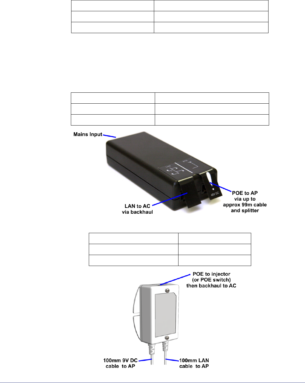
Power over Ethernet
POE requires the use of a power inserter and a splitter. The power inserter is positioned
close to the backhaul network connection and mains supply, while the splitter is positioned
close to the AP.
This is the POE inserter supplied by ip.access:
Only use the POE splitter supplied by ip.access:
ip.access part number EPS1173R
Input 100-240V ~ 50/60Hz 0.7A
Output +9VDC 1.67A
ip.access part number 109A
Input 100/230V ~ 60/50Hz 0.5/0.25A
Output 48VDC 0.38A
ip.access part number 222A
Input 48VDC 0.35A
Output 9VDC 1.33A

nano3G AP Installation Manual Installation Requirements
N3G_INST_300 v6.3 for N3G_2.0 © ip.access Limited 2010 Page 10
2.3.2 Physical
A nano3G S4 AP may be installed in one of the following ways (see section 3.2.4):
• Free-standing on a flat stable surface.
• Attached to a wall or partition using two screws that engage in keyhole slots in the
rear surface of the AP.
• Attached to a POE splitter using the two screws that engage in keyhole slots in the
rear surface of the AP. The POE splitter in turn attaches to a wall or partition using
two screws.
The unit must be vertical to ensure that air can circulate freely around it.
It is recommended to install the AP with its front surface facing the area requiring cellular
coverage, unobstructed by walls or partitions that may have significant RF attenuation.
2.3.3 IP Bandwidth Requirements
At maximum capacity, a nano3G S4 AP will require:
• Downlink: at least 5Mbps
• Uplink: at least 512Kbps
This will deliver up to 4 voice calls and HSDPA services up to 3.6Mbps.
2.3.4 Sundry Installation Equipment
• To mount the POE splitter or the nano3G S4 AP onto the wall:
• 2 self tapping pan head screws, size No. 6 (approx 3.5mm (0.14in) in
diameter)
• Wall plugs if required
• Suitable drills and screwdriver
Dimensions and
weight
Height 176mm (without stand)
193mm (with stand)
Width 170mm
Depth 51mm
Approximate Weight 0.42 kg (AP only)
Environmental Cooling Vents on the back at top and bottom
Operating Temperature 0°C to 40°C
Operating Humidity 10 to 70% non-condensing
nano3G AP Installation Manual Installation Requirements
N3G_INST_300 v6.3 for N3G_2.0 © ip.access Limited 2010 Page 11
2.4 nano3G E8 AP Site Requirements
In addition to the site requirements for all APs, each E8 AP will require:
• A site for wall mounting
• Power supplied in one of the following ways:
• From the supplied POE injector, which requires a suitable mains power
supply point near the injector - the AP must be within reach of a 100m
Ethernet cable
or
• From a mains adaptor unit, supplied separately, which requires a suitable
mains power supply point near the AP that is within reach of the adaptor’s
cabling
2.4.1 Power
Maximum expected power consumption:
• 20 Watts (Rated +12V or -48V DC)
The nano3G E8 AP supports the following power options:
• Power over Ethernet from a IEEE 802.3at compliant POE+ power source
equipment - a suitable POE+ inserter is supplied with the AP
• Direct power from a suitable DC source (+12V, 2.5A rated centre positive 2.1mm
jack) - a suitable mains adaptor is available separately
These power options are mutually exclusive. When POE+ is used, a DC power adapter
must not be plugged in to the AP and vice versa.
The nano3G E8 AP can be used with any IEEE 802.3at compliant POE+ power source.
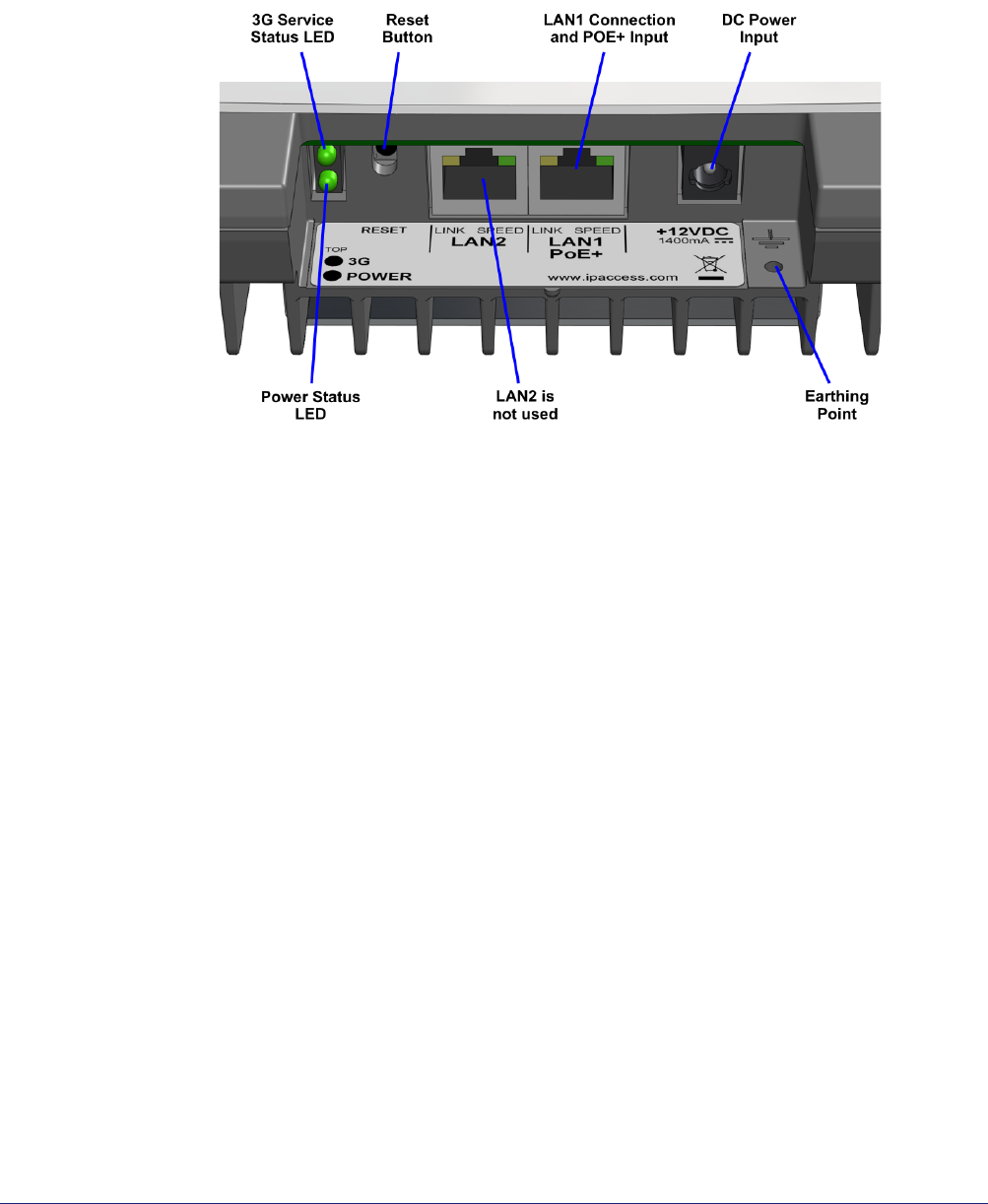
Note: The Ethernet cable carrying POE+ must be plugged into the LAN 1 port. The LAN 2 port,
next to LAN 1, is not used and does not support POE.
nano3G AP Installation Manual Installation Requirements
N3G_INST_300 v6.3 for N3G_2.0 © ip.access Limited 2010 Page 12
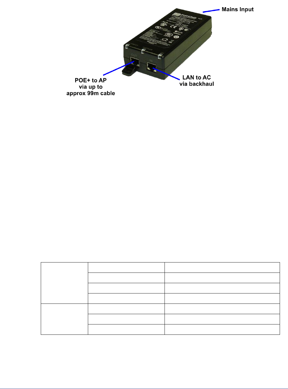
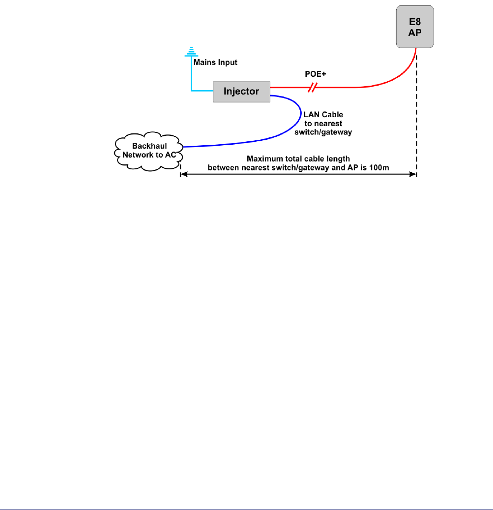
POE+ Injector
The POE+ injector unit is supplied as standard with each nano3G E8 AP. The POE+
injector has two Ethernet connections, one for connection to the main LAN, the other for
connection to the AP. The POE+ injector can be located anywhere on the cable run
between the network switch and the AP, including locally at the AP or remotely at the
network switch.
The POE+ injector is a pass-through connector for the LAN. Its function is to add POE+ to
provide power to the AP. Therefore, the maximum cable run from the network switch to the
AP is 100m, regardless of the placement of the POE+ injector.
The POE+ injector supplied by ip.access complies with LPS requirements in accordance
with IEC/EN 60950-1.
2.4.2 Physical
A nano3G E8 AP is installed by attaching it to a wall or partition using the two screws which
engage in keyhole slots in the rear surface of the AP (see section 3.3.6).
Pay attention to ensure that air can circulate freely around the unit. The unit must be
vertical.
It is recommended to install the AP with its front surface facing the area requiring cellular
coverage, unobstructed by walls or partitions that may have significant RF attenuation.
Dimensions and
weight
Height 211mm
Width 274mm
Depth 58.6mm
Approximate Weight 1.75 kg
Environmental Cooling Vents on the back at top and bottom
Operating Temperature 0°C to +45°C
Operating Humidity 10 to 70% non-condensing

nano3G AP Installation Manual Installation Requirements
N3G_INST_300 v6.3 for N3G_2.0 © ip.access Limited 2010 Page 13
2.4.3 IP Bandwidth Requirements
At maximum capacity, a nano3G E8 AP will require:
• Downlink: at least 7Mbps
• Uplink: at least 1Mbps
This will deliver up to 8 voice calls and HSDPA services up to 7.2 Mbps.
Note: The HSDPA rate of 7.2Mbps is the air-interface rate on Uu. The downlink rate needed to
support this is lower. The uplink assumes a maximum load of 8 UEs each with 64Kbps PS
bearers. Voice traffic has negligible impact.
2.4.4 Installation Tool Requirements
• To mount the bracket onto the wall:
• 6 pan head screws, size No. 6 (approx 3.5mm (0.14in) in diameter) – 4 for
the nano3G E8 AP, 2 for the POE+ adapter
Note: No screws are supplied to mount the AP or the POE+ unit.
• Wall plugs if required.
• Suitable drills and screwdriver.
nano3G AP Installation Manual nano3G AP Hardware Installation
N3G_INST_300 v6.3 for N3G_2.0 © ip.access Limited 2010 Page 14
3 nano3G AP Hardware Installation
This section documents the procedure used to install the nano3G AP hardware and
physical connections together with applying the base software configuration.
Note: If possible, the engineer should stay on site until the AP is brought into service, ready to
make test calls to verify the AP has been configured correctly from the OMC-R.
3.1 Warnings and Regulatory Information
For all warnings and regulatory information, see section 8.
3.2 Hardware Installation - nano3G S4 AP
3.2.1 Unpack the nano3G S4 AP
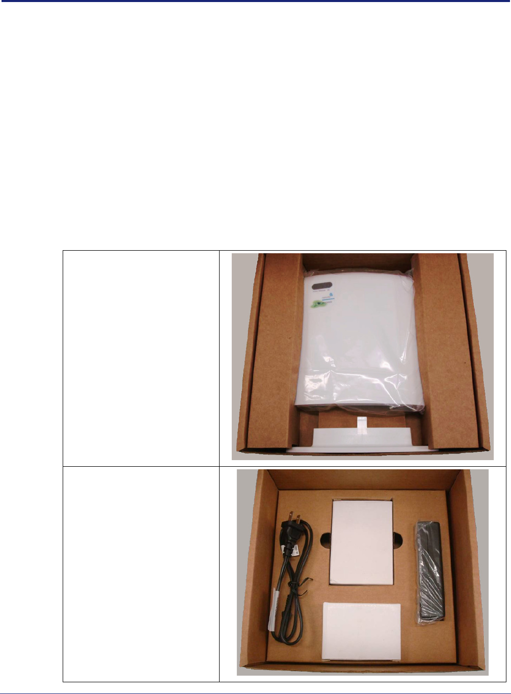
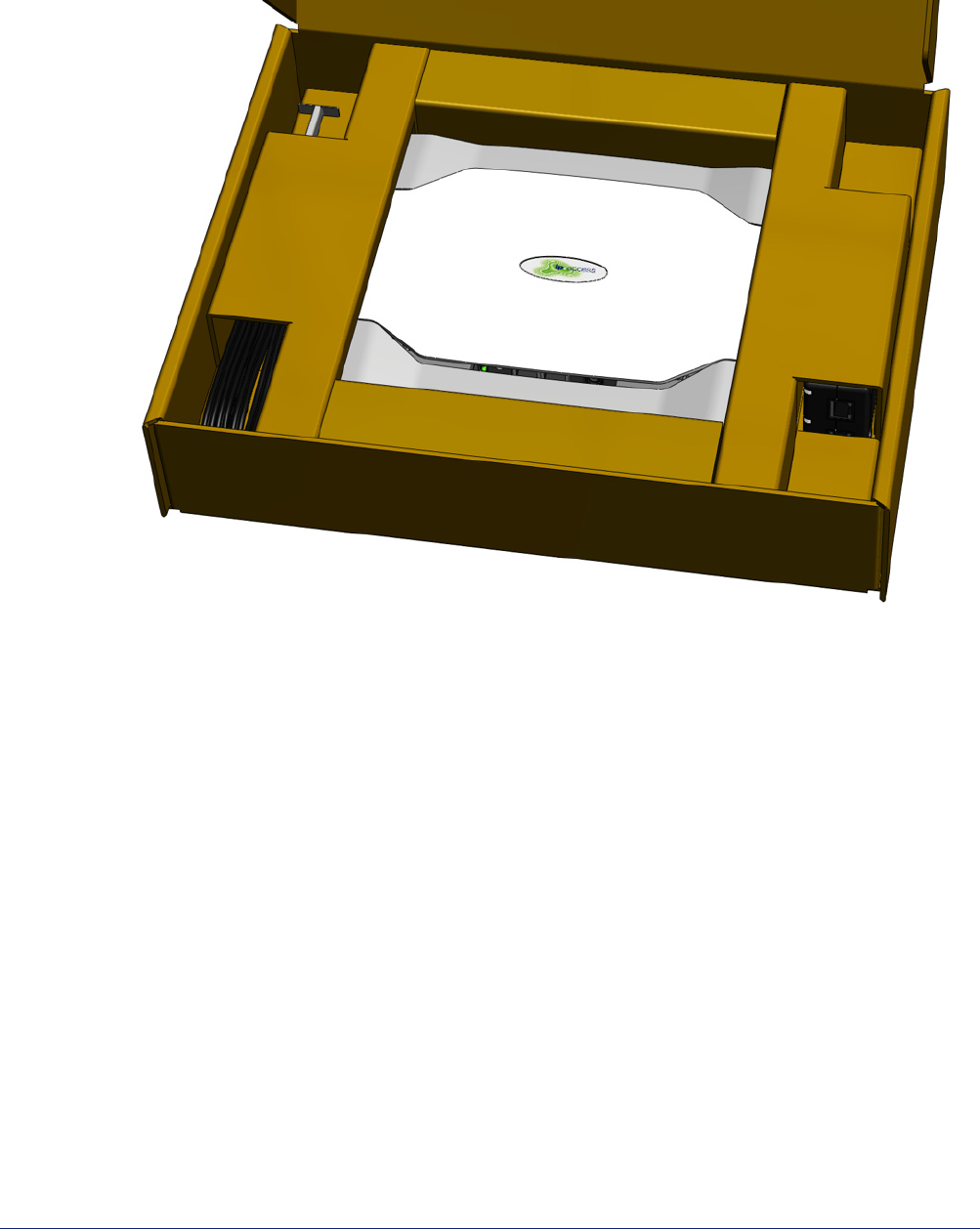
1) Unpack the nano3G S4 AP and its accessories.
Box contents may vary, but typically the box should contain the following, as
pictured:
Upper layer:
• nano3G S4 AP unit
• nano3G S4 AP stand
Lower layer:
• POE injector unit
• POE splitter unit
• Mains adaptor unit
• Mains cable for POE
injector
nano3G AP Installation Manual nano3G AP Hardware Installation
N3G_INST_300 v6.3 for N3G_2.0 © ip.access Limited 2010 Page 15
Note: No screws are supplied to mount the AP or the splitter unit.
2) Check that the serial number on the nano3G S4 AP unit matches the label on the
box.
3) Check that the items have not been damaged in transit.
For any damaged units, contact the supplier immediately for returns advice.
3.2.2 Commission the nano3G S4 AP
Configure the AP so that it will connect to its serving AC. If this has not been done already,
do this now, before installing the AP in its final location. For instructions, see section 4.
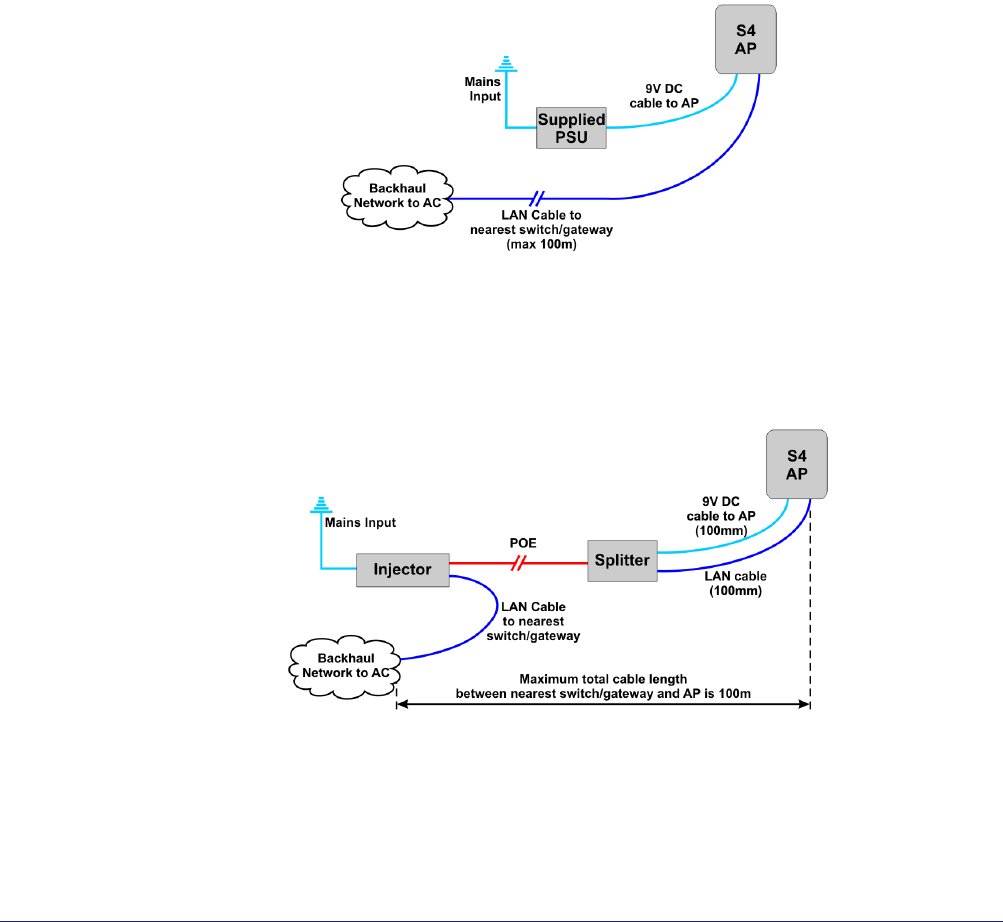
3.2.3 Cable Connections
Use one of the cable connection schemes described below, to provide power and the LAN
connection.
Supplied PSU and LAN
When the supplied PSU is used to power the AP, the POE injector and splitter units are not
needed. However, this means that the mains socket providing power to the AP must be
within reach of the cabling included with the supplied PSU (less than 2m).
POE Injector and Splitter
This improves flexibility for locating the AP, as the AP can be up to approximately 100m
from a mains power supply, depending on the placement of the POE Injector.
In this case, the PSU for the AP is not used. The injector takes a direct mains input using
the supplied mains cable.
nano3G AP Installation Manual nano3G AP Hardware Installation
N3G_INST_300 v6.3 for N3G_2.0 © ip.access Limited 2010 Page 16
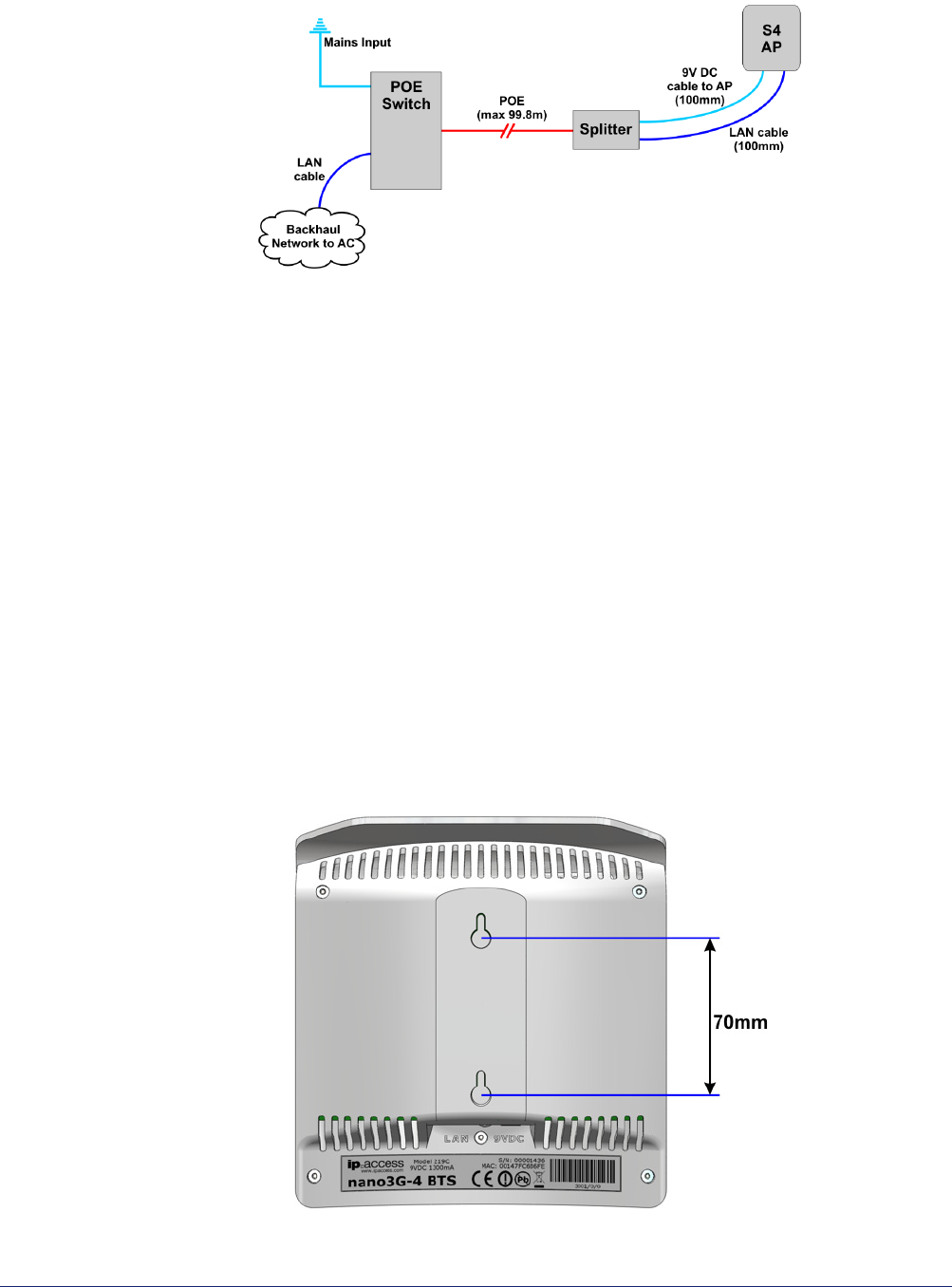
POE Switch and Splitter
In this case, the POE switch is a third-party item. This has similar benefits to using the POE
injector, but a POE switch will typically only be used if there are multiple APs on site and/or
there is other equipment that can take advantage of POE. The supplied POE splitter must
be used with the AP.
Notice that the POE cable to the splitter should not exceed 99.8m in length. This will ensure
that the total cable run from the POE switch to the AP is within the Ethernet limit of 100m.
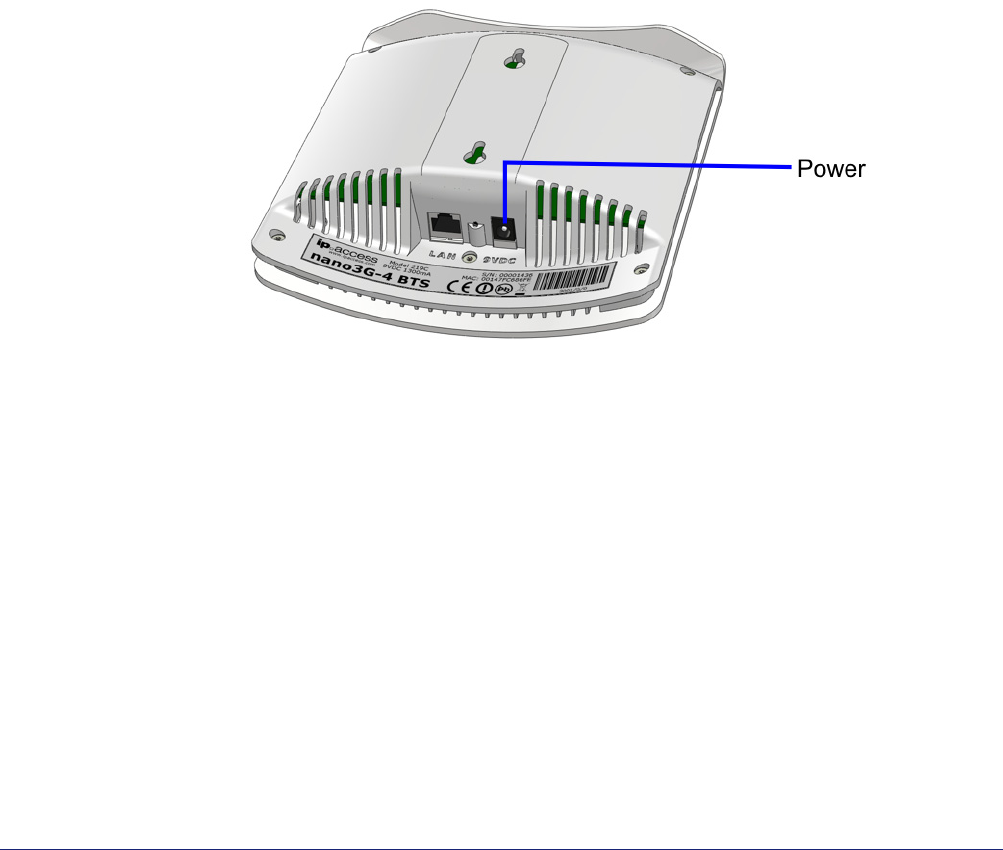
3.2.4 Mount the nano3G S4 AP
Note: The nano3G S4 AP should be installed in a position so that it is at least 2m away from the
area where handsets are normally used.
The nano3G S4 AP must be mounted vertically in a location that allows air circulation
around the unit. The AP can be mounted in the following ways:
• On a stand
• Directly onto the wall at or above head height
• Onto the splitter unit on the wall at or above head height
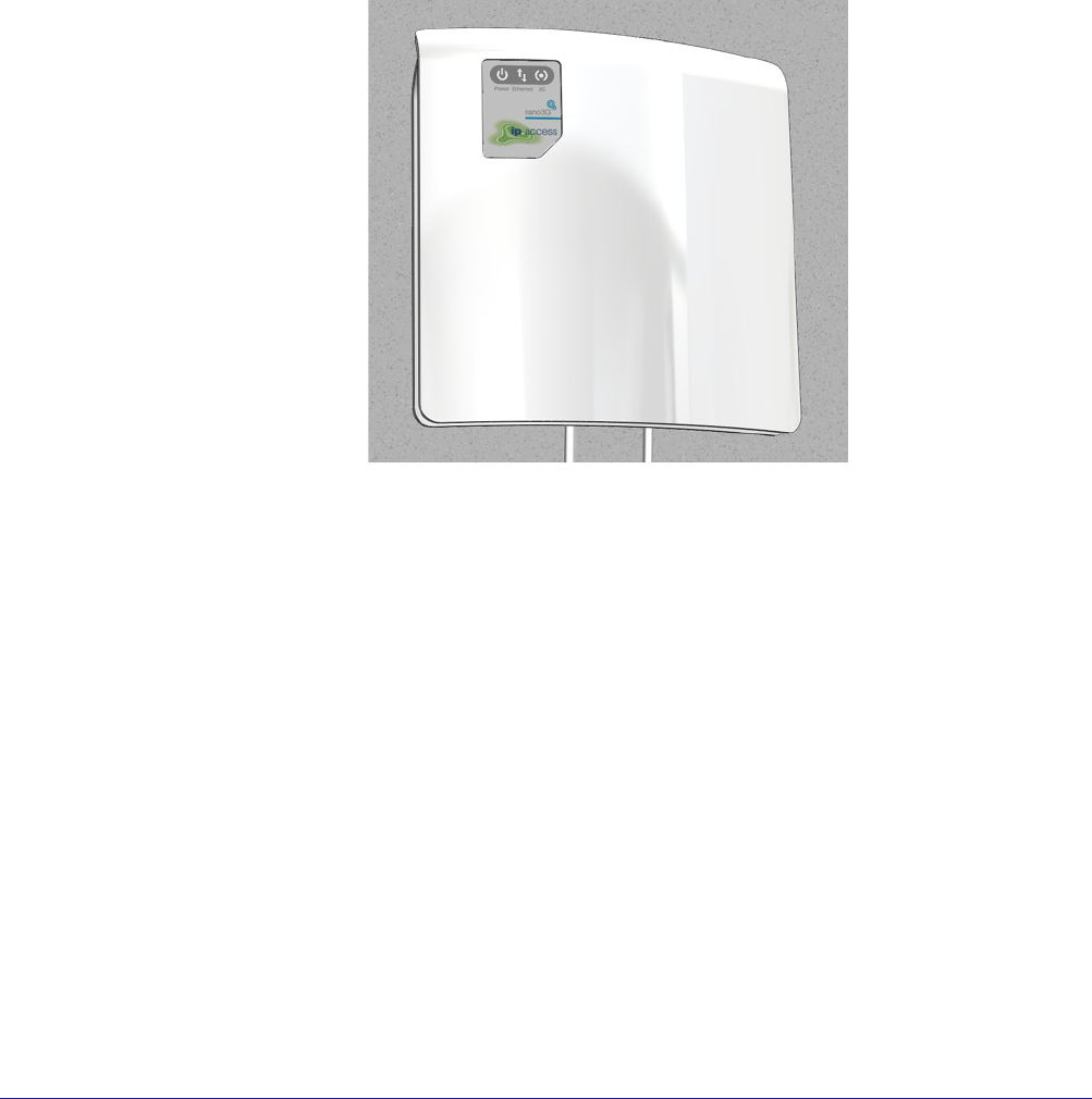
The nano3G S4 AP has two holes at the back for direct wall mounting or mounting on the
POE splitter:
nano3G AP Installation Manual nano3G AP Hardware Installation
N3G_INST_300 v6.3 for N3G_2.0 © ip.access Limited 2010 Page 17
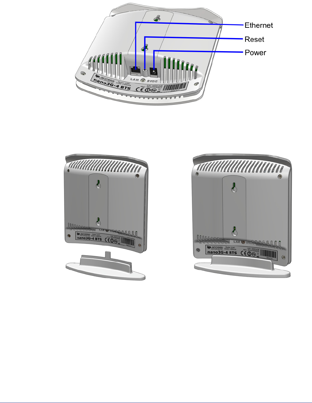
Mount the nano3G S4 AP on a Stand
1) Plug the Ethernet cable and the power cable into the AP or plug the cables from
the POE splitter into the AP.
2) Slide the AP onto the stand.
3) Place the AP on its stand on a stable flat surface.
nano3G AP Installation Manual nano3G AP Hardware Installation
N3G_INST_300 v6.3 for N3G_2.0 © ip.access Limited 2010 Page 18
Mount the nano3G S4 AP directly onto the wall
1) Drill two holes 70mm (2.76in) apart vertically for the two screws.
2) Insert wall plugs (if required) and secure the screws leaving approximately 3mm
(0.12in) clearance between the screw heads and the wall.
3) Plug the Ethernet cable and the power cable into the AP.
Note: If using the POE splitter when wall mounting the AP, it is recommended to
mount the AP directly on the POE splitter, as in the following section. In
some cases, it may be necessary to mount the AP and the POE splitter on
the wall separately to minimise how far the AP projects from the wall. In
this case, position the POE splitter below the AP where the 100mm
cables will reach the AP.
4) Slide the AP onto the 2 screws.
nano3G AP Installation Manual nano3G AP Hardware Installation
N3G_INST_300 v6.3 for N3G_2.0 © ip.access Limited 2010 Page 19
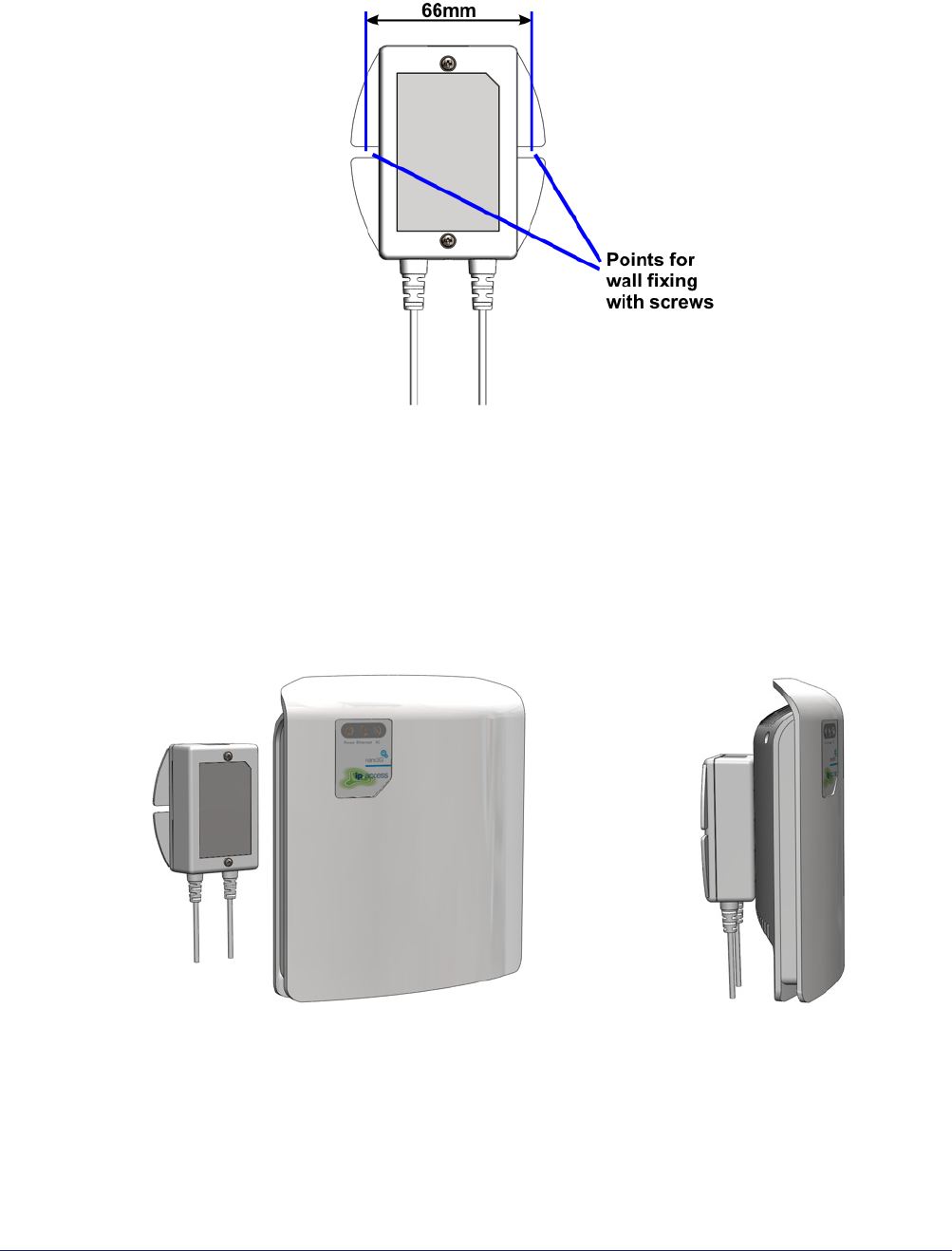
Mount the nano3G S4 AP onto the splitter unit on the wall
1) Drill two holes 66mm (2.6in) apart horizontally for the two screws.
2) Secure the splitter unit to the wall using two screws.
Ensure that the Ethernet socket is at the top.
3) Plug the Ethernet cable into the top of the splitter unit.
4) Plug the captive Ethernet cable and the power cable from the splitter unit into the
AP.
5) Mount the AP onto the 2 screws that are already fixed onto the splitter unit.
nano3G AP Installation Manual nano3G AP Hardware Installation
N3G_INST_300 v6.3 for N3G_2.0 © ip.access Limited 2010 Page 20
3.3 Hardware Installation - nano3G E8 AP
3.3.1 Unpack the nano3G E8 AP
1) Unpack the nano3G E8 AP and its accessories.
Box contents may vary, but typically the box should contain the following:
• nano3G E8 AP unit with wall bracket attached
• Extraction tool for removing the AP from its wall bracket
• Injector unit for POE+
• Mains cable for the POE+ injector
2) Check that the serial number on the nano3G E8 AP unit matches the label on the
box.
3) Check that the items have not been damaged in transit.
For any damaged units, contact the supplier immediately for returns advice.
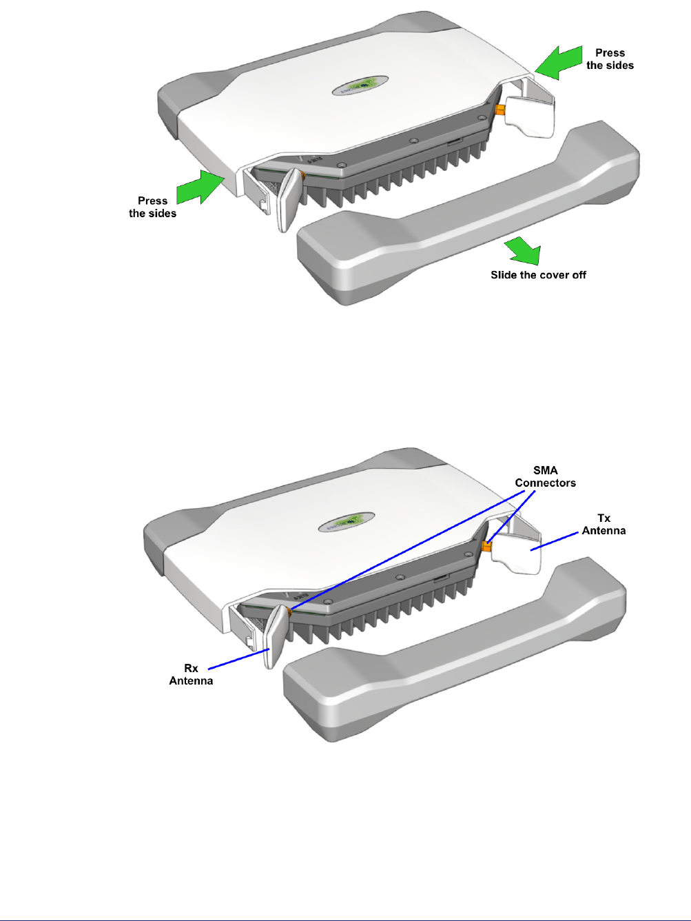
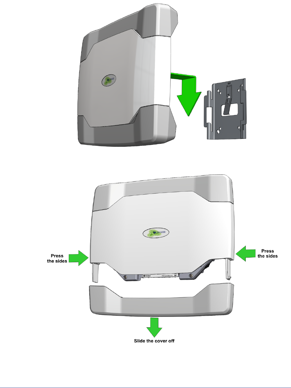
3.3.2 Removable Cable and Antenna Covers
The nano3G E8 AP has two removable covers. The top cover goes over the antennae, and
the bottom cover goes over the cable sockets.
1) Place the unit on a flat surface.
nano3G AP Installation Manual nano3G AP Hardware Installation
N3G_INST_300 v6.3 for N3G_2.0 © ip.access Limited 2010 Page 21
2) Press the sides of the unit next to the cover to be removed. Do not apply excessive
force.
3) Slide the cover off.
4) To refit the cover, simply slide it back onto the tabs on the main cover until it snaps
into place.
3.3.3 Antennas
The antennas must be oriented perpendicular to the unit, as shown, so that the cover fits
correctly without stressing the connectors.
To fit external antennas, first remove the plastic cover from the antenna side of the unit.
Unscrew the antennas to expose the SMA connectors. Connect external antennas directly
to the SMA connectors. Route the cables out of the way of the antenna cover, then refit the
cover.
nano3G AP Installation Manual nano3G AP Hardware Installation
N3G_INST_300 v6.3 for N3G_2.0 © ip.access Limited 2010 Page 22
3.3.4 Commission the nano3G E8 AP
Configure the AP so that it will connect to its serving AC. If this has not been done already,
do this now, before installing the AP in its final location. For instructions, see section 4.
3.3.5 Cable Connections
Two power supply modules are available from ip.access, designed for use with the
ip.access nano3G E8 AP and are compliant with the IEEE 802.3at standard:
• The POE+ injector, as supplied, is commonly used for single site installations
• Direct power from the mains via an optional power adapter
POE+ Injector
The AP can be up to 100m from the switch/gateway to the backhaul, but allow
approximately 0.1m for routing through the injector. The injector can be positioned
anywhere on this cable run. Hence the injector can be at the most convenient point for
providing power, without restricting the location of the AP.
The injector takes a direct mains input using the supplied mains cable. Use a CAT5
Ethernet cable that is capable of carrying POE from the injector to the AP.
nano3G AP Installation Manual nano3G AP Hardware Installation
N3G_INST_300 v6.3 for N3G_2.0 © ip.access Limited 2010 Page 23
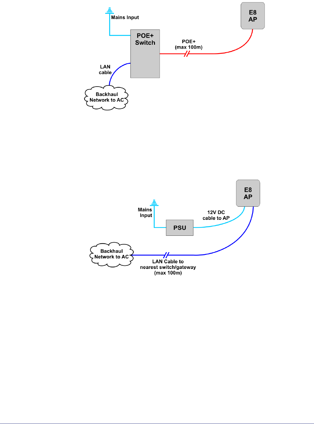
POE+ Switch
In this case, the POE+ switch is a third-party item. The cable run from the switch to the AP
can be a full 100m.
A POE+ switch will typically only be used if there are multiple APs on site and/or there is
other equipment that can take advantage of POE+.
PSU and LAN
When a suitable PSU is used to power the AP (see section 2.4.1) the POE+ injector unit is
not needed. However, this means that a mains socket providing power to the AP must be
within reach of the cabling included with the PSU. This is typically less than 2m. The PSU
for the E8 AP is an optional extra.
3.3.6 Mount the nano3G E8 AP on a Wall
Note: The nano3G E8 AP should be installed in a position so that it is at least 2m away from the
area where handsets are normally used.
The nano3G E8 AP must be mounted vertically to ensure air circulation around the unit.
The location of each nano3G E8 AP is shown on the installation floor plan produced at the
network planning stage. For example, it must take into account that all APs must be at least
2m from any mobile equipment. The network wiring must be complete before the nano3G
E8 AP can be installed and commissioned. The nano3G E8 AP should be placed on a wall
at or above head height.
nano3G AP Installation Manual nano3G AP Hardware Installation
N3G_INST_300 v6.3 for N3G_2.0 © ip.access Limited 2010 Page 24
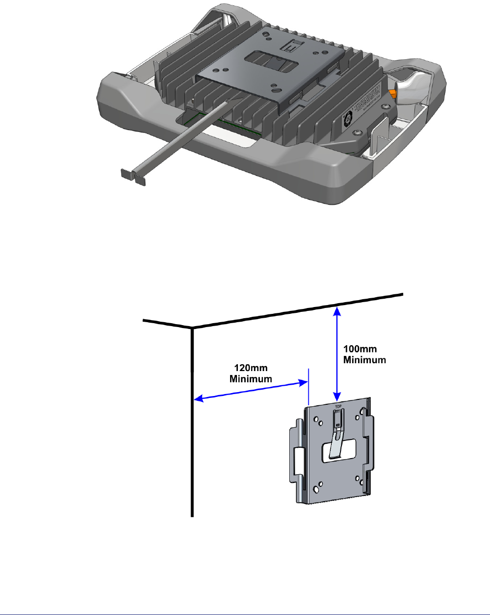
1) Remove the nano3G E8 AP from the wall bracket. Lay the AP on a flat surface with
the wall bracket upwards. Slide the removal tool over the central fin between the
bracket and the body of the unit to disengage the locking spring, then slide the
bracket to separate it from the AP. The removal tool may be inserted from the top
or bottom of the nano3G E8 AP.
2) Position the bracket on the wall with its flat surface against the wall and the clip
part towards the top. Ensure the bracket is level and sufficient clearance is
maintained to allow the AP to be fitted to the bracket. Allow at least 100mm from
the bracket to the top of wall, and 120mm from the side of the bracket to a side
wall.
3) Mark the position of the four screw holes.
4) Drill the four holes in the positions marked previously and insert wall plugs (if
required) and fix the mounting bracket securely to the wall. The bracket is
designed to allow the nano3G E8 AP unit to be mounted with the connections
either at the top or at the bottom of the unit.
nano3G AP Installation Manual nano3G AP Hardware Installation
N3G_INST_300 v6.3 for N3G_2.0 © ip.access Limited 2010 Page 25
5) Slide the nano3G E8 AP onto the bracket and ensure that the retaining spring
engages into the indent at the rear of the unit.
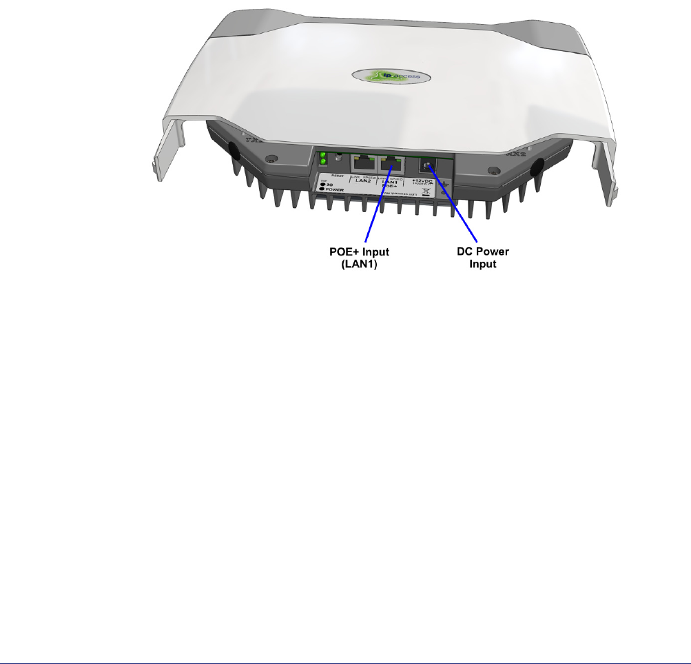
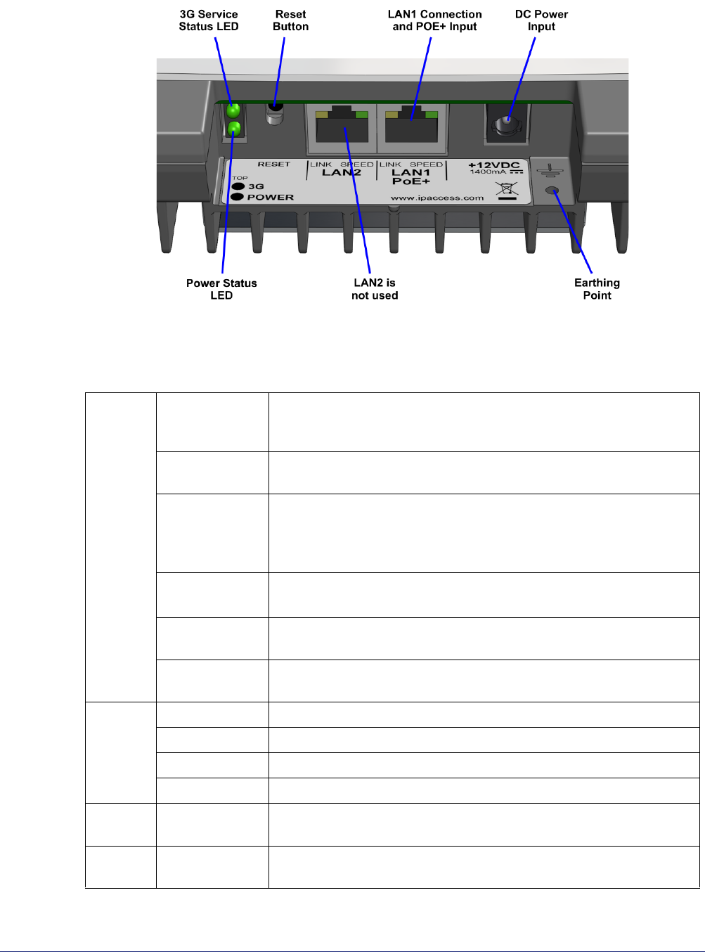
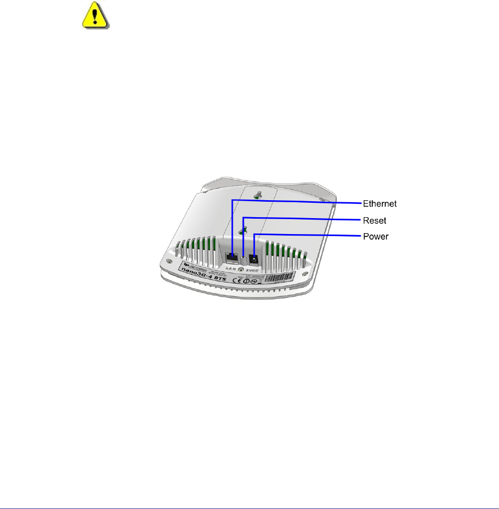
6) Remove the lower cover to reveal the cable ports and LEDs.
nano3G AP Installation Manual nano3G AP Hardware Installation
N3G_INST_300 v6.3 for N3G_2.0 © ip.access Limited 2010 Page 26
7) Plug in the required cables. Either:
• Plug an Ethernet cable from the POE+ injector or POE+ switch into LAN1
or
• Plug an Ethernet cable from a switch/gateway (no POE+) into LAN1 and an
optional power supply into the +12V DC input
Note: Do not connect an Ethernet cable to LAN2. This will have no effect.
8) To refit the lower cover, slide it onto the tabs on the main cover until it snaps into
place.
nano3G AP Installation Manual Commission a nano3G AP
N3G_INST_300 v6.3 for N3G_2.0 © ip.access Limited 2010 Page 27
4 Commission a nano3G AP
This procedure provisions the nano3G AP with the settings it needs to establish a
connection with its serving nano3G AC. Once commissioning is complete, use the OMC-R
Client for further configuration and to bring the AP into service.
An AP can be commissioned in advance of the site visit or can be commissioned on site via
a provisioning laptop. This procedure assumes on-site provisioning with a laptop.
The nano3G AP must be in the factory reset state for this procedure. If a factory reset is
required, see section 7.2 for instructions.
4.1 Configure a Provisioning Laptop to Connect to the AP
1) Connect the AP and the provisioning laptop with an Ethernet cable.
2) Open the Windows Control Panel on the laptop.
3) Go to Network Connections.
4) Right-click the relevant Local Area Connection and select Properties.
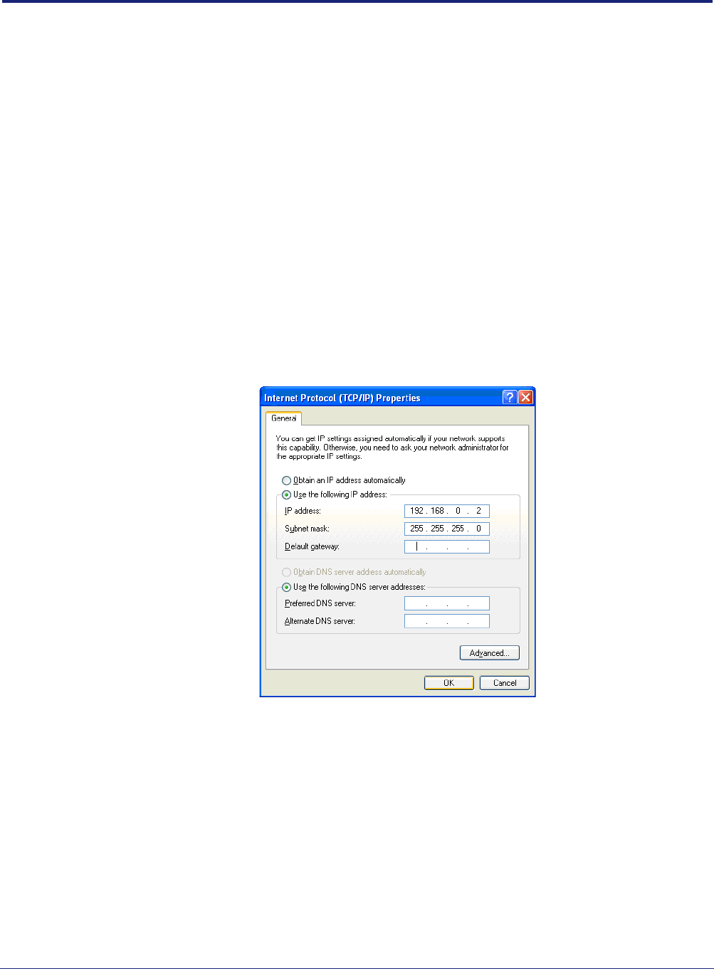
5) In the list of items on the General tab, select Internet Protocol (TCP/IP) and then
click Properties. The following dialogue appears:
6) If it is not possible to leave this network connection permanently configured for AP
commissioning, make a note of the current settings.
7) Click the Use the following IP address radio button.
8) Set the IP Address to 192.168.0.2.
9) Set the Subnet Mask to 255.255.255.0.
10) There is no default gateway, so ensure the default gateway address is cleared.
11) Click OK to close and save the changes in each of the two dialogues. Also close
the Control Panel.
nano3G AP Installation Manual Commission a nano3G AP
N3G_INST_300 v6.3 for N3G_2.0 © ip.access Limited 2010 Page 28
4.2 Configure the AP-AC Connection
12) Power up the AP.
For the nano3G S4 AP, either:
• Use the power supply provided with the AP
or
• Connect the short power cable from the POE Splitter unit - this will also
require power into the splitter unit from a POE source
For the nano3G E8 AP, typically do one of the following:
• Connect the laptop to the LAN input on the POE+ injector unit, connect a
cable to carry POE+ from the injector to the LAN1 port on the AP, then plug
the POE+ injector into the mains
or
• Connect the optional power supply for the AP to the AP’s 12V DC input, and
connect the laptop to the LAN1 port on the AP
13) Start a web browser on the laptop.
14) In the address bar, enter the pre-defined static IP address and port number for the
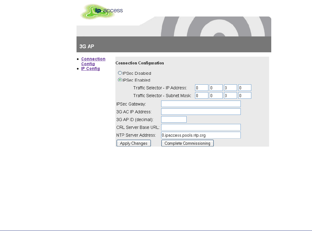
web server: http://192.168.0.1:8089. A login screen appears.
15) Enter the commissioning user name and the password (supplied separately for
security reasons). The Connection Config page appears:
nano3G AP Installation Manual Commission a nano3G AP
N3G_INST_300 v6.3 for N3G_2.0 © ip.access Limited 2010 Page 29
4.2.1 Static IP Configuration
Obtaining an IP address with DHCP is recommended for the nano3G AP, and this is
selected by default. Only execute this section if static IP configuration is needed. This
must be done before completing the Connection Config page.
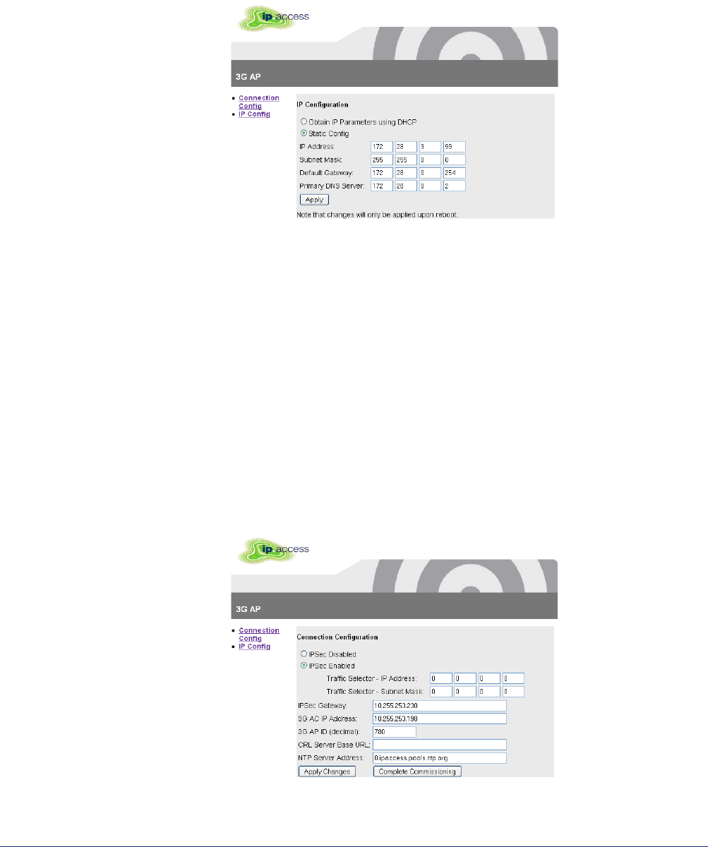
16) If static IP is required, click the IP Config link on the left. The IP Configuration page
appears.
17) Edit the parameters as needed and then click Apply.
Note: At this point it may be useful to make a separate note of the parameter
values entered in this screen. Alternatively, save a screenshot of the web
page (information about how to take a screenshot is outside the scope of
this manual).
18) Click the Connection Config link on the left.
4.2.2 Configure the AC Connection
19) If Secure Connection is required, select IPSec Enabled, and enter the IPSec
Gateway and Traffic Selector addresses.
20) Enter the IP address of the AC and the NTP server (do not use the values shown -
these are examples only).
21) Enter the ID of the AP. This must be the same as the Cell ID assigned to the AP.
22) To save the configuration, click Apply Changes.

nano3G AP Installation Manual Commission a nano3G AP
N3G_INST_300 v6.3 for N3G_2.0 © ip.access Limited 2010 Page 30
Note: At this point it may be useful to make a separate note of the parameter
values entered in this screen. Alternatively, save a screenshot of the web
page (information about how to take a screenshot is outside the scope of
this manual).
23) To start the AP in normal operation mode, click Complete Commissioning.
24) Acknowledge the warning about changes in the IP configuration and click OK.
25) When the initial configuration is complete, power off the AP and disconnect it from
the laptop.
At this point, the commissioning web page is no longer accessible. If there are
configuration errors that prevent the AP connecting to its serving AC, the
commissioning procedure must be started again after resetting the AP with a
factory reset. See section 7.2 for factory reset instructions.
26) Mount the AP at its intended location, as in section 3.2.4 or 3.3.6.
27) Connect the AP to the operator network.
28) Power up the AP. Either use the power supply provided with the AP, or connect the
short power cable from the POE Splitter unit.
The AP performs its normal, deployed mode start-up and connects to its serving
AC. During this procedure, the nano3G AP obtains network time and day
information from the NTP server. If IPsec is in use, the AP establishes an IPsec
tunnel to the Security Gateway.
From this point on, the AP must be managed from the OMC-R. It is now ready for
initial configuration, typically by NOC engineers, as in section 6.

nano3G AP Installation Manual Configuration File Preparation
N3G_INST_300 v6.3 for N3G_2.0 © ip.access Limited 2010 Page 31
5 Configuration File Preparation
A nano3G AP holds the master copy of its own configuration. Therefore, it cannot be pre-
provisioned in the OMC-R. However, the attribute values for configuring a nano3G AP can
be stored in a text file, and then loaded via the OMC-R Client to provision the AP.
This section describes how to prepare one or more text files of attributes for provisioning
nano3G APs. This may be done at any time, but it is recommended to do as much as
possible in advance of the site visit to install an AP.
The main reason for preparing a configuration file to provision an AP is to help bring the AP
into service as quickly as possible. This can be done in combination with configuration
adjustments from the OMC-R Client, according to whichever method is best suited for given
configuration tasks.
5.1 Overview of Attribute Configuration Files
An attribute configuration file is a text file containing an object class followed by a list of
attribute names and the value applied to each attribute. The file can also contain comment
lines anywhere that start with the # character. Hence, the file is of the form:
# some comment about the object type
Object=class_nnn
# some other comment
attribute1=value
attribute2=value
...
attributeN=value
The file must contain the Object type. The OMC-R Client will not load a file that does not
have an Object type defined. For N3G_2.0, the Object for a nano3G AP must be
apNano8_001 or apNano_002. So in each case the file must start like this:
• For a nano3G E8 AP
Object=apNano8_001
• For a nano3G S4 AP
Object=apNano_002
An attribute configuration file can be created from scratch. More conveniently, a file can be
saved from within the OMC-R Client from an object of the same type and then customized
for a different object of the same class. The resulting configuration file can then be imported
against the target object, which in this case will be an AP.
An example file is provided in section 5.3.
Configuration files must be imported one at a time, but there is no restriction on the number
of configuration files that can be imported to configure any given object. This means it is
possible to create a generic template file, which contains attribute values common to all
APs of the same type. Typically, this can be started by exporting the configuration from an
AP that has already been fully configured, and then edited to remove non-generic
attributes. Once the generic template has been created, optionally create a file for each
individual AP with additional settings particular to each AP. However, if the majority of

nano3G AP Installation Manual Configuration File Preparation
N3G_INST_300 v6.3 for N3G_2.0 © ip.access Limited 2010 Page 32
required settings are in the generic template, it may be easier to simply load the template
then use the OMC-R Client for fine tuning the configuration of an individual AP.
The ObjectInstance must be removed from a generic template if the original file was created
by export from the OMC-R Client. If required, a configuration file for a specific AP can
include the ObjectInstance value for that AP. This will ensure the file can only be loaded
against the target AP. However, this must be reproduced exactly or the configuration file will
not load against the target AP. A way around this is to save a configuration file for that AP,
regardless of its configuration state, then copy and paste the ObjectInstance into the file
that has the correct configuration.
Note: All of the attributes can be configured from the OMC-R Client. After initial provisioning from
a configuration file the OMC-R Client can be used to set attributes or the configuration file
can be edited to set more parameters, for example when importing configuration
information from a radio planning system. To obtain a sample file with all the attributes that
can be configured, export a configuration file as described in section 5.2 and inspect its
content.
5.1.1 Attribute Types and Values
The attribute types and values conform to the attribute definitions in the MIB. See
[REF_110] for a full description of each object type, the attributes it may contain and the
valid values that may be assigned to each attribute.
The following attribute types are available, which are also formally described in [REF_110]:
• Base types:
• Integer - a whole number numeric value, often must be within a range of valid
values
tos=0
• Enumeration, or enum - a value name from a pre-defined set of names with
specific values
t300=T300_4000_MSEC
• Boolean - a true or false value
soipHeartbeatEnabled=true
• String - a value enclosed in double-quotes (the double-quote character itself
cannot be part of the value)
mnc="12"
• Compound types that are made of multiple instances of any types:
• Array - a comma delimited set of values of the same type within square
brackets [ ]
ascPersistenceScalingFactors=[6,6,6,6,6,6]
• Structure - a comma delimited set of values within curly brackets { }, and
each value can be of any type
cellBroadcastMessage={50,GSM_DEFAULT,"nano3G"}
• Set - similar to an array, this a comma delimited set of values of the same
type within round brackets ( ), however, each value must be different
rfParamsCandidateList=({1062,437,1})
nano3G AP Installation Manual Configuration File Preparation
N3G_INST_300 v6.3 for N3G_2.0 © ip.access Limited 2010 Page 33
Note: In the OMC-R Client, the compound types are the complex attributes that have multiple
levels within the Navigation and Properties panes.
Note: In [REF_110], there is a distinction between expert and non-expert attributes. As a general
rule, it is recommended to leave expert attributes at their default values.
5.2 Create a nano3G AP Attribute Configuration File
A file can be created from scratch in a text editor, or can be started from the configuration of
an existing AP.
To create a configuration file from scratch, simply open a text editor and enter the required
configuration details.
For information on the syntax of the configuration file, see section 5.1.
For example configuration files, see section 5.3.
To start a configuration file by saving the configuration of an existing AP:
1) Start an OMC-R Client session.
Note: For full information on using the OMC-R Client, see [OPM_410].
2) In the Explorer pane of the OMC-R Client, find and select a suitable 3G AP object
to use as a template. That is, select an AP of the same type as the target AP.
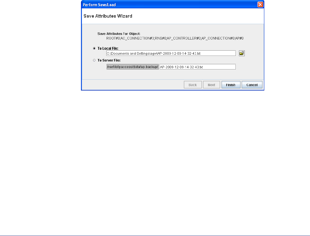
3) Right-click on the AP object and select Save Attributes to File. The Save
Attributes Wizard will appear.
4) Select the radio button for the required location. For the purposes of creating a
template for another AP, saving To Local File is recommended.
When saving To Local File, the target directory and file name may be changed.
When saving To Server File (on the OMC-R Server), the directory and file name
are set automatically and cannot be changed. The file is named as follows:
AP-<Serial_number>-<Object_name>-<Date_Time>.txt
Where the <Serial_number> for the AP ensures the file name is unique, the
<Object_name> can make individual APs easier to identify and the <Date_Time>
is the date and time the file was created.
5) Click Finish to save the configuration file.
The file will contain all writable attributes. That is, all attributes that can be changed
from within the OMC-R Client. Most of these will be at default values.

nano3G AP Installation Manual Configuration File Preparation
N3G_INST_300 v6.3 for N3G_2.0 © ip.access Limited 2010 Page 34
6) Edit the file in a suitable text editor, and adjust the configuration as needed for the
new AP, or any number of new APs. If the file will be used as a general template
that will be loaded on multiple APs, remove the ObjectInstance= line from the file.
Note: Use a text editor that can edit Unix text files. Windows® WordPad can be
used, but Notepad is not suitable.
5.3 Example AP Configuration Files
5.3.1 Example Generic Template File for nano3G S4 AP
The following example file shows the attributes that are typically the same for all AP on the
same AC. This is a manually created example, rather than being based on a file exported
from an existing AP.
Object=apNano_002
#
# Cell Package
rncIdentity=139
#
# NAS Package
mcc="159"
mnc="12"
sac=1
saiLac=1
#
# Network Listen Control Package
rfParamsCandidateList=({1062,437,1})
rssiScanBands=({BAND_NAME_UMTS_BAND_04_NO_SPOT,()})
neighbourListPopulation=STATIC_ONLY
# to scan all bands, use the empty value: rssiScanBands=()
#
# 3G AP Diagnostics Package
diagnosticReporting=({REPORT_ON_CRASH,"http://oam.server/upload/diagnostic"})
#
# 3G AP Measurement Control Package
reportingUrl=http://oam.server/upload/pm/ap
#
# 3G AP Time Package
localTimeZone=PST8PDT
#
# end of file
Parameter Description
Object Object type for APs, must be apNano_002 or apNano8_001
rncIdentity RNC ID of the AC
mcc Mobile Country Code
mnc Mobile Network Code
sac This is the SAI SAC (Service Access Code) which can be used
by the billing system. If this is not used by the billing system, it is
recommended to set this to 1.
saiLac SAI Location Area Code which can be used by the billing system.
This is a different value than the LAC set in the
lacRacCandidateList for an individual AP. If this is not used by
the billing system, it is recommended to set this to 1.

nano3G AP Installation Manual Configuration File Preparation
N3G_INST_300 v6.3 for N3G_2.0 © ip.access Limited 2010 Page 35
5.3.2 Example AP-Specific Configuration File
The following example file shows the attributes that are unique for each AP. This is a
manually created example, rather than being based on a file exported from an existing AP.
Object=apNano_002
#
# Network Listen Control Package
lacRacCandidateList=({15912,(99)})
rfParamsCandidateList=({1062,437,1})
rfScanControl={"0200",1440,240,true}
#
# Location Package
lcsLongitude=-2540
lcsLatitude=695
lcsUncertainty=15
#
# end of file
rssiScanBands Specify which bands to scan with Network Listen, when
performing RSSI detect and BCCH decode tests. Leave this
empty to scan all bands supported by the AP hardware.
neighbourListPopulation This determines how the live neighbour list is populated. The
recommended setting is STATIC_ONLY, which only uses
neighbours entered in the static neighbour lists, as determined
by network planning.
diagnosticReporting for S4 APs
or diagnosticReporting_001 for
E8 APs
Set the URL of the OAM File Server diagnostics service. Replace
oam.server with the IP address or FQDN of the server.
reportingUrl Set the URL of the OAM File Server measurement reporting
service. Replace oam.server with the IP address or FQDN of the
server.
localTimeZone Set the timezone, in POSIX format, where the APs are located.
This assumes that all APs on the same AC are in the same
timezone, which is the most probable scenario. If APs are spread
across several timezones, this can be an AP-specific setting.
Parameter Description
Parameter Description
Object Object type for APs, must be apNano_002 or apNano8_001
lacRacCandidateList LAC and RAC for the AP.
rfParamsCandidateList Set the UARFCN, Scrambling Code and Cell ID to be used by the
AP.

nano3G AP Installation Manual Configuration File Preparation
N3G_INST_300 v6.3 for N3G_2.0 © ip.access Limited 2010 Page 36
5.3.3 Other Attributes
The following table shows some other attributes to consider for inclusion in AP configuration
files. Apart from the static neighbour lists, which are usually configured individually, any of
these can be in a general template for all APs or can be set individually.
rfScanControl This is composed of:
• The scan time, as HHMM, for the first scan, after which
the scans take place every time the interval passes - if
this is daily, set the time when usage is expected to
be low so that the NWL scan does not disrupt the
service
• The interval in minutes, the default value of 1440 is one
day, or set to 0 to disable periodic scans
• The randomization period in minutes, which ensures
multiple APs in close proximity do their scans at different
times
• Use reduced scan, true or false: a reduced scan is faster
but may not detect all changes to the RF environment
Note: Depending on deployment requirements, this could be in the
general template instead.
lcsLongitude This is entered as a number for east (positive) or west (negative) of
the Greenwich meridian. It may be easier to enter this directly in
the OMC-R Client, as this allows entry in degrees, minutes and
seconds.
lcsLatitude This is entered as a number for north (positive) or south (negative)
of the equator. It may be easier to enter this directly in the OMC-R
Client, as this allows entry in degrees, minutes and seconds.
lcsUncertainty Radius of uncertainty in metres.
Parameter Description
Parameter Description
Admission Control Package
psHandoverEnabled Whether or not PS RABs will handover between an AP and the
macro network. This is disabled (false) by default.
Network Listen Control Package
neighbourPlmns If specified, this restricts the networks that neighbouring cells can
belong to for populating the neighbour lists by specifying the
MCC/MNC values.
plmnsToSyncWith If specified, this restricts the networks that neighbouring cells can
belong to for frequency synchronisation by specifying the MCC/
MNC values.

nano3G AP Installation Manual Configuration File Preparation
N3G_INST_300 v6.3 for N3G_2.0 © ip.access Limited 2010 Page 37
staticGsmNeighbourList This is a complex attribute that specifies GSM (2G) neighbour
candidates. It is recommended to enter these directly in the OMC-
R Client. However, if a similar list has already been configured for
a nearby AP, it may be advantageous to copy this attribute from a
configuration file saved from the nearby AP, load this into the
target AP and then make suitable adjustments from the OMC-R
Client.
See [OPM_300] for information on neighbour list configuration.
staticUmtsNeighbourList This is a complex attribute that specifies UMTS (3G) neighbour
candidates. It is recommended to enter these directly in the OMC-
R Client. However, if a similar list has already been configured for
a nearby AP, it may be advantageous to copy this attribute from a
configuration file saved from the nearby AP, load this into the
target AP and then make suitable adjustments from the OMC-R
Client.
See [OPM_300] for information on neighbour list configuration.
Oscillator Synchronisation Package
oscillatorSynchronisationTim
eout
The number of days an AP can go without resynchronisation
before it raises the relevant alarm.
Parameter Description
nano3G AP Installation Manual Configuring a nano3G AP from the OMC-R
N3G_INST_300 v6.3 for N3G_2.0 © ip.access Limited 2010 Page 38
6 Configuring a nano3G AP from the OMC-R
The nano3G AP needs to be configured before it is brought into service. All the remaining
configuration changes must be applied via the OMC-R Client, typically by a NOC engineer.
6.1 Check and Upgrade the nano3G AP Software Image
6.1.1 Check the Current Software Image Version
1) Login to the OMC-R Client with a user name (and password) that has Full Access
rights for changing the AP's configuration.
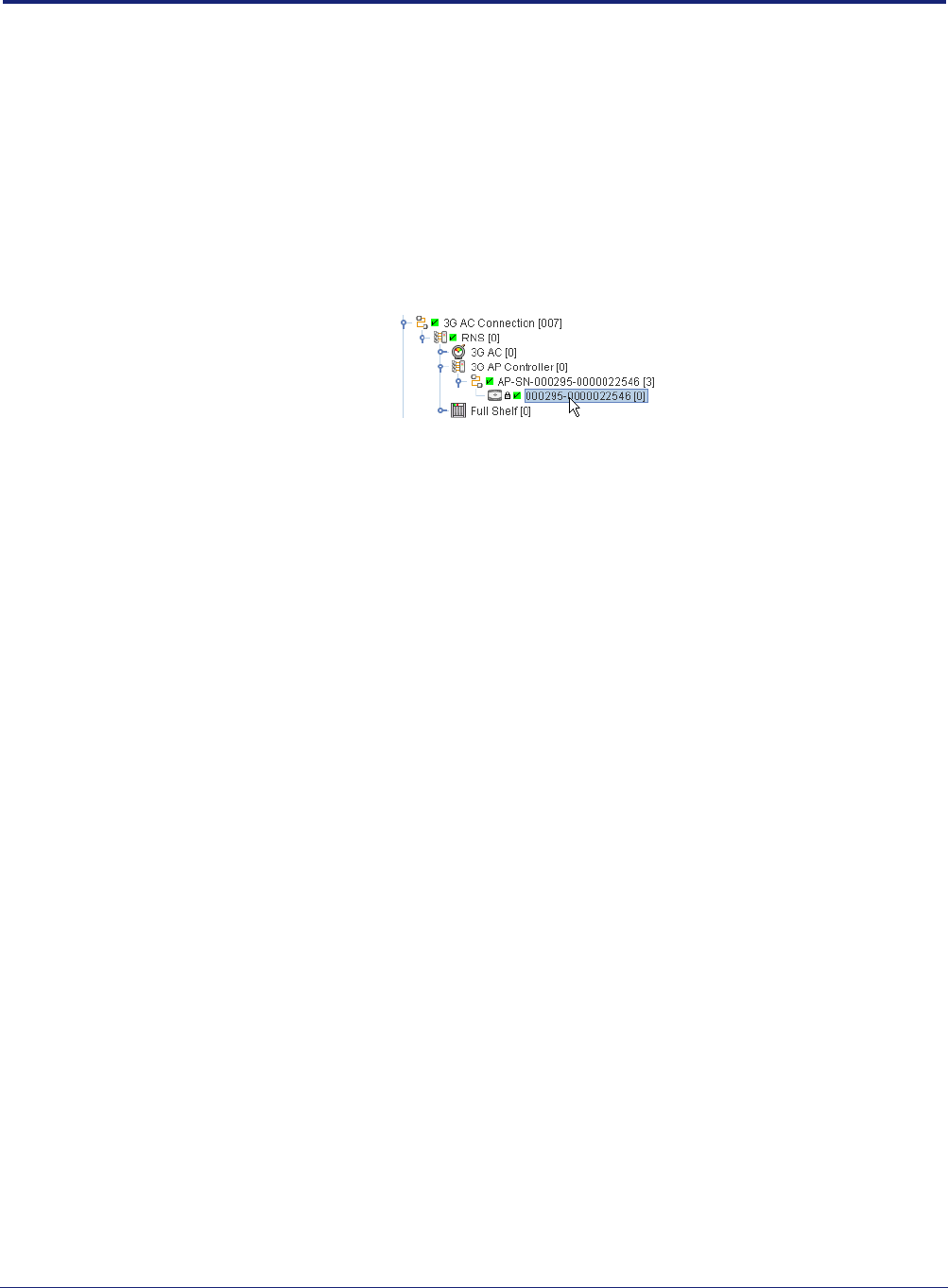
2) Find the AP according to its serial number and select the AP object.
Note: For full information on using the OMC-R Client, see [OPM_410].
3) Verify that the AP Connection has a green tick, to show that the AP is connected
to the AC. The AP object, below the AP Connection, is currently locked. The AP
will remain locked until it is properly configured and ready to provide service.
4) In the Navigation pane, browse to the AP Admin Package.
5) Check the values of the Active SW Version and Standby SW Version attributes.
6) If the AP does not have the latest software image, download it to the AP from the
OAM File Server according to the instructions below.
6.1.2 Download the Latest Software Image from the OAM File Server to
the AP
For instructions about how the software images (SDP files) are uploaded to the OAM File
Server, see [OPM_430].
1) Select the AP in the OMC-R Client.
nano3G AP Installation Manual Configuring a nano3G AP from the OMC-R
N3G_INST_300 v6.3 for N3G_2.0 © ip.access Limited 2010 Page 39
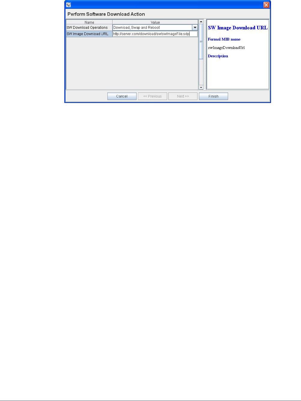
2) Right-click the AP, select Actions and then Perform Software Download. The
Perform Software Download Actions dialogue box will appear.
3) Change the SW Download Operations to Download, Swap and Reboot.
4) Click in the SW Image Download URL box and enter the URL of the required SDP
file using the following URL pattern:
http://<server>/download/sw/<filename>.sdp
Where <server> is the IP address or host name of the required OAM File Server,
and <filename>.sdp is the required software download package file.
5) Press <TAB> or <Enter> to set the URL.
6) Click Finish and the download will take place. On the AP, download progress is
indicated by the flashing network LED. When the download is complete, the AP will
reboot under the new software, which should take less than 1 minute.
7) Wait for the AP to be shown as connected to the OMC-R.
8) Select the 3G AP Admin Package for the AP object and verify that the Filesys
version reported by the Active Software Version matches the SDP file that was
downloaded.
6.2 Apply an Attribute Configuration to the AP
1) Ensure the attribute configuration file is available on the OMC-R Server or the
computer running the OMC-R Client. For information on preparing an AP
configuration file, see section 5.
2) Log in to the OMC-R Client with a user name that has Full Access to the AP.
3) To start the OMC-R Load Attributes Wizard, right-click on the AP object in the
OMC-R Client and then select Load Attributes From File.
4) Browse to the edited configuration file and click Apply to load and apply the
configuration settings.
If any of the loaded values are inconsistent with the current state of the AP or if any
of the values are illegal, the wizard displays a warning.
5) Repeat as needed, if there are multiple configuration files.

nano3G AP Installation Manual Configuring a nano3G AP from the OMC-R
N3G_INST_300 v6.3 for N3G_2.0 © ip.access Limited 2010 Page 40
6.3 Finalize Configuration
1) Login to the OMC-R Client with a user name that has Full Access to the required
AP.
6.3.1 Final Attribute Changes and Checks
2) Make any AP-specific configuration changes that have not already been applied by
loading configuration files. In particular, ensure the static neighbour lists are
correctly configured. See [OPM_300] for information on neighbour list
configuration.
3) Spot check any or all of the following packages to verify the attributes have been
set correctly by the configuration file(s):
• Cell Package
•NAS Package
• Location Package
6.3.2 Network Listen and Frequency Correction
4) To execute a Network Listen scan, right-click the AP object, select Actions and
then select Start Sequential NWL Scan.
5) When the scan is complete, view the results and verify there is some radio activity
detected, and ideally some neighbour cells. This will confirm the radio is working.
6) Only if a suitable macro neighbour has been detected, a correction can be applied
to ensure that the oscillator frequency is correct. Select Actions and then select
Apply Frequency Correction.
Note: Assuming there is a suitable macro neighbour, this should be repeated
approximately 24 hours after the AP is brought into service. This will allow
time for the oscillator crystal to stabilize, at which time the frequency
correction should be re-applied.
6.3.3 Automatic Configuration Backup
The configuration of an AP is automatically backed up on the OMC-R server each time
configuration changes are applied from the OMC-R Client. The configuration files are
named according to the AP serial numbers. A file is overwritten automatically by
subsequent configuration changes. The files are saved in:
/var/lib/ipaccess/data/auto-ap-backup
6.4 Bring the AP into Service
Once the AP has the latest software image and configuration is complete, it is ready for
service.
1) To bring the AP into service, right-click the 3G AP object in the OMC-R Client and
select Unlock. The padlock symbol next to the 3G AP icon will be removed.
2) If the installation engineer is still on site, the engineer should make CS and PS test
calls to verify the AP is providing service.
nano3G AP Installation Manual Troubleshooting
N3G_INST_300 v6.3 for N3G_2.0 © ip.access Limited 2010 Page 41
7 Troubleshooting
7.1 LED Status Indicators
7.1.1 nano3G S4 AP LEDs
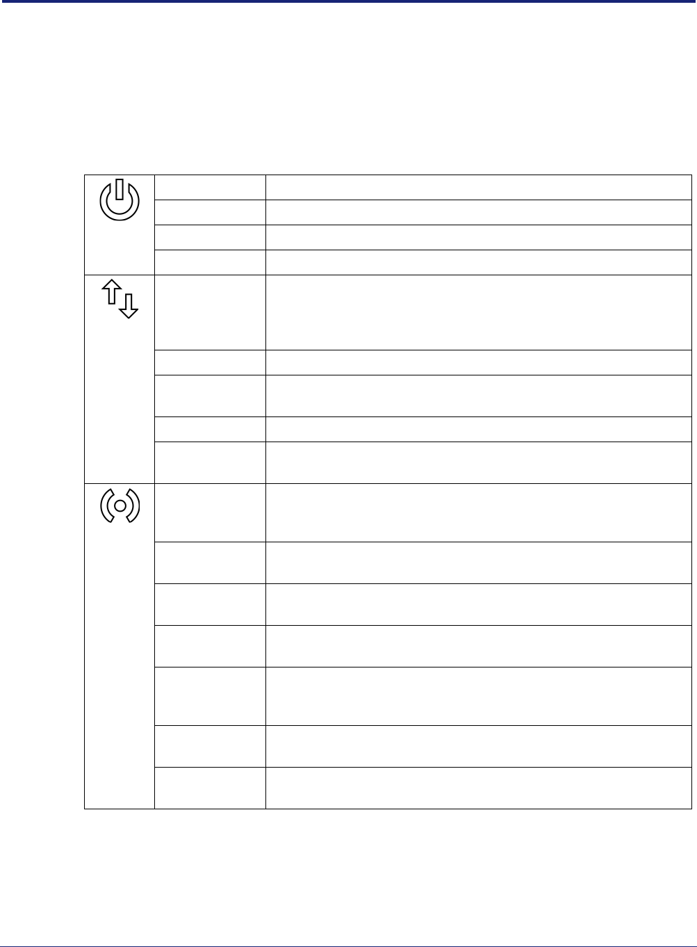
The following table shows the meaning of the status LEDs under normal and fault
conditions.
Power
Off The nano3G AP is not switched on.
Green The nano3G AP is powered up normally.
Flashing green Self-test is running.
Red There is a fault with the nano3G AP.
Network
Off Unable to detect a network. This is usually because there is no
network cable connected, or there is no network connection at the
other end of the cable (for example, the router or broadband modem
may have failed).
Green The 100Mbps connection is OK.
Flashing green Indicates activity on the network at 100Mbps speed (that is, the
nano3G AP is sending and/or receiving data across the LAN).
Amber The 10Mbps connection is OK.
Flashing amber Indicates activity on the network at 10Mbps speed (that is, the
nano3G AP is sending and/or receiving data across the LAN).
Service
Off The nano3G AP is not provisioned, it has no IP address. This may
be a temporary condition when the AP is switched on for the first
time, or after factory reset.
Green The nano3G AP is provisioned and unlocked, it is connected to the
AP and is providing service.
Flashing green
(evenly, slowly)
The nano3G AP is provisioned but has lost connection to the AC, for
example because the AC is not available or there is a DNS problem.
Flashing green
(evenly, fast)
The nano3G AP has been reinitialized (the reset button was pressed
but for less than 5 seconds).
Off, with a short
green blink every
3 seconds
The nano3G AP is administratively Locked.
Off, with short
green blinks on
Factory reset is in progress in the nano3G AP (the reset button was
pressed for more than 5 seconds).
On, with short
green blinks off
Software download is in progress to the nano3G AP.
nano3G AP Installation Manual Troubleshooting
N3G_INST_300 v6.3 for N3G_2.0 © ip.access Limited 2010 Page 42
7.1.2 nano3G E8 AP LEDs
The following table shows the meaning of the status indicators under normal and fault
conditions.
3G Off The nano3G E8 AP is not provisioned, it has no IP address. This
may be a temporary condition when the AP is switched on for the
first time, or after factory reset.
Green The nano3G E8 AP is provisioned and unlocked, it is connected to
the AC and is providing service.
Flashing green
(evenly, slowly)
The nano3G E8 AP is provisioned but has lost connection to the AC,
for example because the AC is not available or there is a DNS
problem.
The nano3G E8 AP is has been locked.
Flashing green
(evenly, fast)
The nano3G E8 AP has been reinitialized (the reset button was
pressed but for less than 5 seconds).
Off, with short
green blinks on
Factory reset is in progress in the nano3G E8 AP (the reset button
was pressed for more than 5 seconds).
On, with short
green blinks off
Software download is in progress to the nano3G E8 AP.
Power Off The nano3G E8 AP is not switched on.
Green The nano3G E8 AP is powered up normally.
Flashing green Self-test is running.
Red There is a fault with the nano3G E8 AP.
Ethernet
Link
Amber This is on to show the link is active, or flashes when there is network
activity.
Ethernet
Speed
Green Shows the network speed. On for 100Mbps or off for 10Mbps.
nano3G AP Installation Manual Troubleshooting
N3G_INST_300 v6.3 for N3G_2.0 © ip.access Limited 2010 Page 43
7.2 Backhaul Network Connection Problems
If static IP addressing is disabled and DHCP is in use, the nano3G AP expects to be
automatically provided with an IP address by the broadband router every time it starts.
Ensure that the DHCP service is enabled on the broadband router.
7.3 Factory Reset
A factory reset will delete all configuration settings that have been applied to an AP. This
includes the initial configuration applied to commission the AP so that it will connect to its
serving AC, and all configuration changes subsequently applied from the OMC-R.
Therefore, executing a factory reset will mean that the AP will not provide service until it is
recommisssioned from the commissioning laptop and then reconfigured from the OMC-R.
Note: If the reset button is pressed for less than 5 seconds, the AP will reboot. It will not return to
the factory reset state.
7.3.1 nano3G S4 AP Factory Reset
To perform a factory reset, use a thin rod to press and hold the reset button for more than 5
seconds.
The Service LED will blink fast (50ms on, 50ms off) until the factory reset commences, then
it will start to blink slowly (200ms on, 200ms off). When the factory restore process is
complete, the LED will extinguish and the AP will automatically reboot. The AP will have the
fixed IP address used for initial commissioning and will enable the web interface for
configuration. Commission the AP to connect to its serving AC, as in section 4, then
configure the AP from the OMC-R, as in section 6.
WARNING
Only use the reset button to return the AP to factory reset state as a last resort,
such as when the AP does not connect to the AC. After a factory reset, the AP will
need to be commissioned again manually, as in section 4.2.
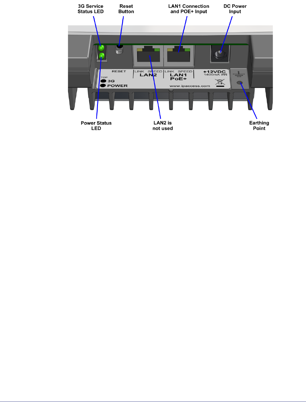
nano3G AP Installation Manual Troubleshooting
N3G_INST_300 v6.3 for N3G_2.0 © ip.access Limited 2010 Page 44
7.3.2 nano3G E8 AP Factory Reset
To perform a factory reset, press and hold the reset button for more than 5 seconds.
The 3G LED will blink fast (50ms on, 50ms off) for 5 seconds, then it will start to blink slowly
(200ms on, 200ms off). When the factory restore process has completed, the LED will
extinguish and the AP will automatically reboot, take the fixed IP address and enable the
web interface for configuration (see section 4).
7.4 nano3G E8 AP Does Not Start Up
• Check the power-over-Ethernet inserter: it must be a POE+ unit
• Verify the Ethernet cable from the POE+ inserter is plugged into the correct socket
(LAN1)
• If using a DC power supply instead of POE+, verify the power supply is a 12V
supply with the correct polarity
nano3G AP Installation Manual nano3G AP and PSU Regulatory Information
N3G_INST_300 v6.3 for N3G_2.0 © ip.access Limited 2010 Page 45
8 nano3G AP and PSU Regulatory Information
This chapter provides the customer with safety and regulatory warnings, cautions and
information for the ip.access Ltd range of products.
8.1 Warnings and Cautions
Electrical Safety
CAUTION
The nano3G AP is intended for dry indoor applications only. If evidence of
condensation is present do not apply power to the nano3G AP.
CAUTION
The nano3G AP is designed to be operated as a fixed system device and must be
located away from the user. It must be mounted in a manner to ensure that all
users and bystanders are kept a minimum of 20cm away from the integral
antennas at all times.
WARNING
Do not immerse any part of the nano3G AP or its power supply in water or any
other liquid. Do not install or use the nano3G AP or its power supply near open
water. Do not spill liquids of any type on the nano3G AP or its power supply.
WARNING
Do not use liquid, solvent or aerosol cleaning agents on or near the nano3G AP or
its power supply.
CAUTION
To avoid the risk of fire and/or electrical shock, do not push objects through
openings into the nano3G AP or its power supply (except when operating the
Reset switch on the nano3G AP).
CAUTION
Do not disassemble the nano3G AP or its power supply.
CAUTION
The nano3G AP must only be powered using the ip.access power supply provided
for use with the nano3G AP.
CAUTION
Before using the power supply, verify that the mains voltage is within the range
specified by the voltage printed on the power supply.
CAUTION
The PSU supplied with the nano3G AP must not be used for powering any other
equipment.
CAUTION
To avoid the risk of fire and/or electrical shock, do not overload power outlets or
extension cables.
CAUTION
When disconnecting the power supply from the mains, pull the plug. Pulling the
cable may result in damage to the cable.
nano3G AP Installation Manual nano3G AP and PSU Regulatory Information
N3G_INST_300 v6.3 for N3G_2.0 © ip.access Limited 2010 Page 46
Interference with Electronic Devices
Other Warnings and Cautions
CAUTION
If using a pacemaker, ensure you are using the device in accordance with its
safety requirements with respect to RF devices. Consult your doctor if you have
questions about RF signals and your pacemaker.
CAUTION
If using a hearing aid, RF devices may cause interference.
CAUTION
Unshielded electronic devices should not be used near the nano3G AP.
Conversely, the nano3G AP should not be installed adjacent to unshielded
electrical or electronic devices (such as unshielded speakers).
WARNING
Do not install the nano3G AP in a position where the power supply cable or
network cable may cause a tripping or choking hazard.
WARNING
Do not install the nano3G AP or the power supply on an unstable surface. All
caution must be observed to prevent the device from falling and causing injury to
a person and/or damage to the device.
WARNING
The nano3G AP should not be disposed of in household waste bins. Please follow
local regulations for disposal of electronic devices.
CAUTION
Do not install the nano3G AP in a position where the power supply cable or
network cable may be damaged by walking on the cables.
CAUTION
Do not attempt to fit an external antenna or antenna cabling to the nano3G S4 AP.

nano3G AP Installation Manual nano3G AP and PSU Regulatory Information
N3G_INST_300 v6.3 for N3G_2.0 © ip.access Limited 2010 Page 47
8.2 Regulatory Statements for nano3G S4 AP
8.2.1 Type Approval and EMC Standards
• FCC CFR47 Parts 15B, 27
Note: Changes or modifications not expressly approved by the party responsible for compliance
may void the user's authority to operate this equipment.
Model nano3G 219C has FCC ID QGGIPA219C
Note: This equipment has been tested and found to comply with the limits for a class B digital
device, pursuant to part 15 of the FCC rules. These limits are designed to provide
reasonable protection against harmful interference when the equipment is operated in a
commercial environment. This equipment generates, uses, and can radiate radio frequency
energy and, if not installed and used in accordance with the instruction manual, may cause
harmful interference to radio communications. Operation of this equipment in a residential
area is likely to cause harmful interference in which case the user will be required to correct
the interference at his own expense.
8.2.2 Safety Standards
• IEC 60950-1:2005 (2nd Edition) and EN 60950-1:2006
The power adapter, as well as the POE inserter and splitter supplied by ip.access comply
with LPS requirements in accordance with IEC/EN 60950-1.
WARNING
This is a class B product. In a domestic environment this product may cause radio
interference in which case the user may be required to take adequate measures.

nano3G AP Installation Manual nano3G AP and PSU Regulatory Information
N3G_INST_300 v6.3 for N3G_2.0 © ip.access Limited 2010 Page 48
8.3 Regulatory Statements for nano3G E8 AP
8.3.1 Type Approval and EMC Standards
• FCC CFR47 Parts 15B, 27
Note: Changes or modifications not expressly approved by the party responsible for compliance
may void the user's authority to operate this equipment.
Model nano3G 217C has FCC ID QGGIPA217C
Note: This equipment has been tested and found to comply with the limits for a class A digital
device, pursuant to part 15 of the FCC rules. These limits are designed to provide
reasonable protection against harmful interference when the equipment is operated in a
commercial environment. This equipment generates, uses, and can radiate radio frequency
energy and, if not installed and used in accordance with the instruction manual, may cause
harmful interference to radio communications. Operation of this equipment in a residential
area is likely to cause harmful interference in which case the user will be required to correct
the interference at his own expense.
8.3.2 Safety Standards
• IEC 60950-1:2005 (2nd Edition) and EN 60950-1:2006
The POE+ inserter supplied by ip.access complies with LPS requirements in accordance
with IEC/EN 60950-1.
WARNING
This is a class A product. In a domestic environment this product may cause radio
interference in which case the user may be required to take adequate measures.