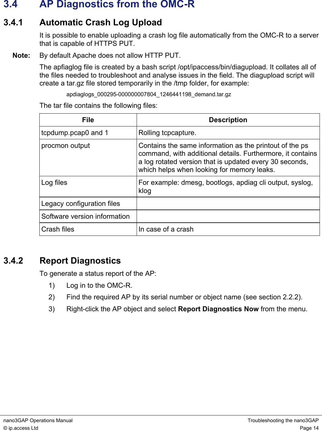
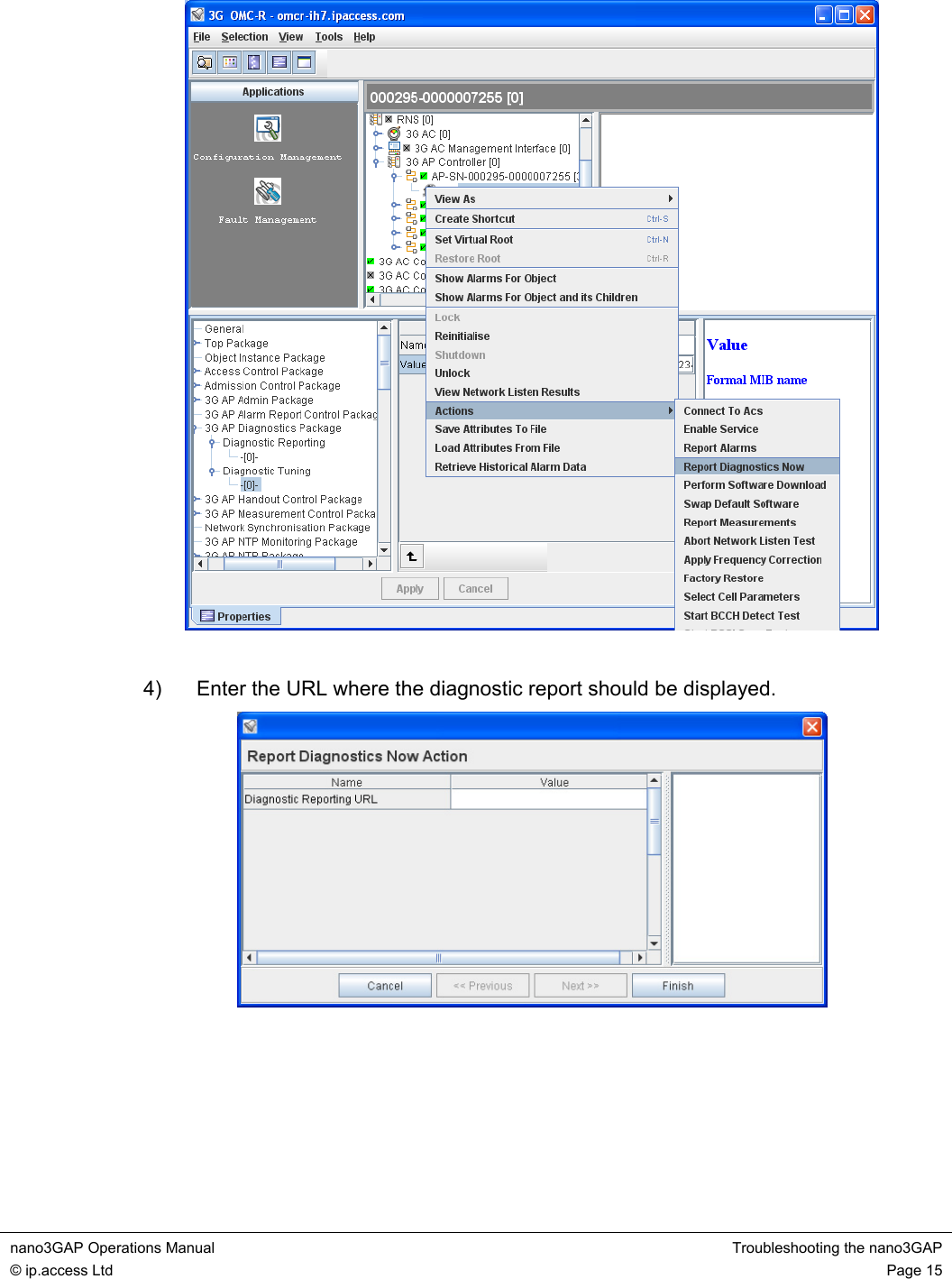
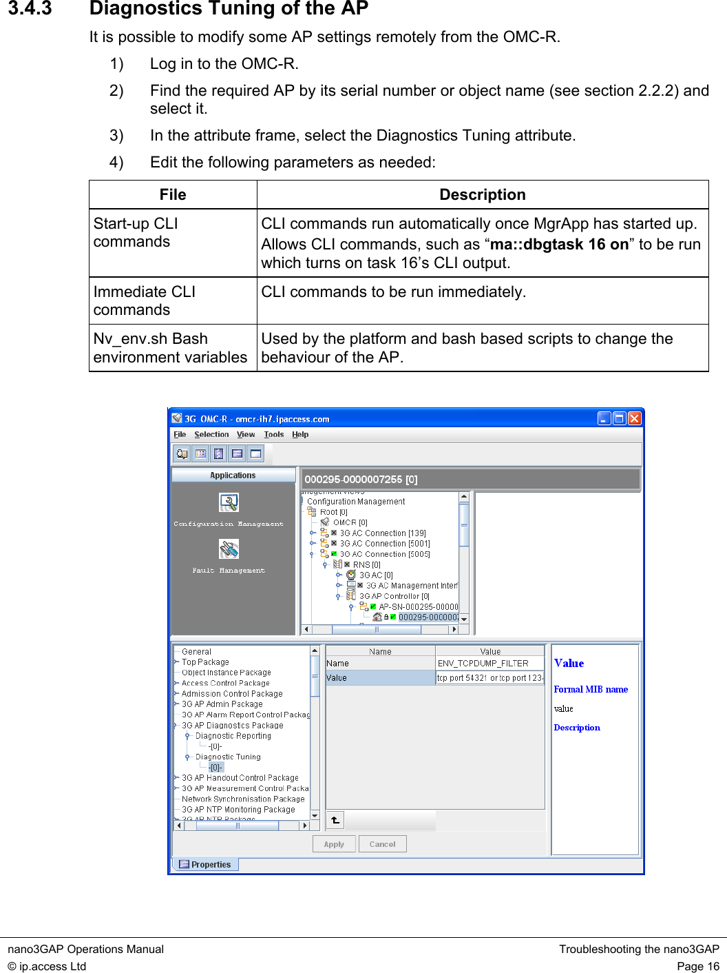
ip access IPA219C 3G Picocellular basestation User Manual nano3GAP Operations Manual
ip.access ltd 3G Picocellular basestation nano3GAP Operations Manual
Contents
- 1. Installation guide
- 2. Operating guide
- 3. Installation manual
- 4. Operating manual
Operating guide
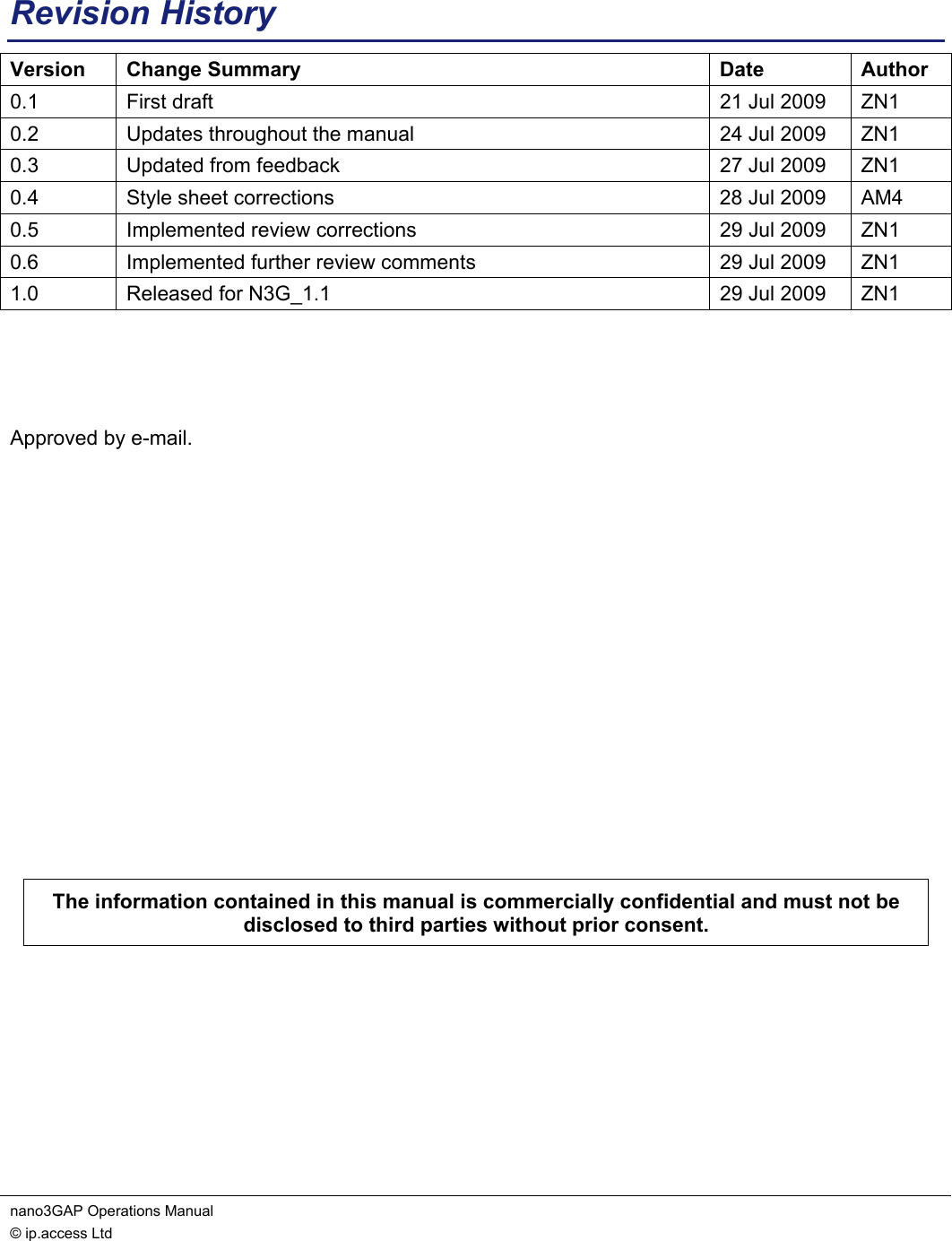
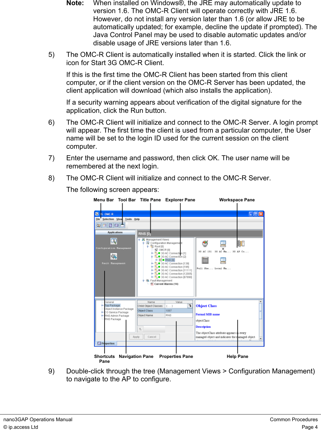
![nano3GAP Operations Manual Introduction © ip.access Ltd Page 1 1 Introduction This document provides information on managing and troubleshooting the ip.access nano3GAP-4 AP, an indoor local area access point. 1.1 Overview This manual is intended for use by individuals engaged in the day-to-day management of the nano3GAPs. It describes direct operation, administration and maintenance of the APs. 1.1.1 Configuration from a Provisioning PC The nano3GAP includes a web server that can be accessed via a web browser running on the provisioning PC. The web server can be used during commissioning only because it is only available when the AP is in the factory reset state. For instructions, see [INST_300]. 1.1.2 Configuration and Administration from the OMC-R Client A nano3GAP can be configured and managed from the OMC-R Client, a Java application that can run on Windows. It connects to the OMC-R Server, which in turn connects to one or more ACs. Hence, the OMC-R Client can provide a view of the whole network. This view may be restricted according to user permissions. Following commissioning (see [INST_300]), nano3GAP objects are created automatically by the AC to which the AP first connected. Once a 3GAP object has connected to a nano3G AC, they are visible in the OMC-R, and they can be configured and managed remotely. When a nano3GAP has been added to the database, its configuration attributes can be changed in the OMC-R Client and additional features, such as Measurement Functions, can be used with the nano3GAP. Furthermore, the OMC-R Client has full alarm management capability. Alarm notifications from a nano3GAP or the controlling AC are grouped into lifecycles according to the unique ID of the object that raised an alarm. Hence, the alarm status of a particular object can be tracked as it changes, until the lifecycles ends when the alarm clears. Alarms can be acknowledged and optionally notes may be added to an alarm. For more information, see [OPM_410]. 1.2 Related Information [GST_100] nano3G System Overview Manual (N3G_GST_100) [GST_300] nano3GAP Product Description (N3G_GST_300) [INST_300] nano3GAP Installation Manual (N3G_INST_300) [OPM_410] nano3G OMC-R Client Operations Manual (N3G_OPM_410) [OPM_430] nano3G PM/DL Server Operations Manual (N3G_OPM_430) [REF_105] nano3G System Glossary (N3G_REF_105)](https://usermanual.wiki/ip-access/IPA219C.Operating-guide/User-Guide-1169424-Page-4.png)
![nano3GAP Operations Manual Introduction © ip.access Ltd Page 2 [REF_130] nano3G Alarm Data Reference Manual (N3G_REF_130) [21.905] Vocabulary for 3GPP Specifications, 3rd Generation Partnership Project 1.3 Terminology For standard nano3G System terminology, see [REF_105]. For additional standard GSM terminology, see [21.905].](https://usermanual.wiki/ip-access/IPA219C.Operating-guide/User-Guide-1169424-Page-5.png)
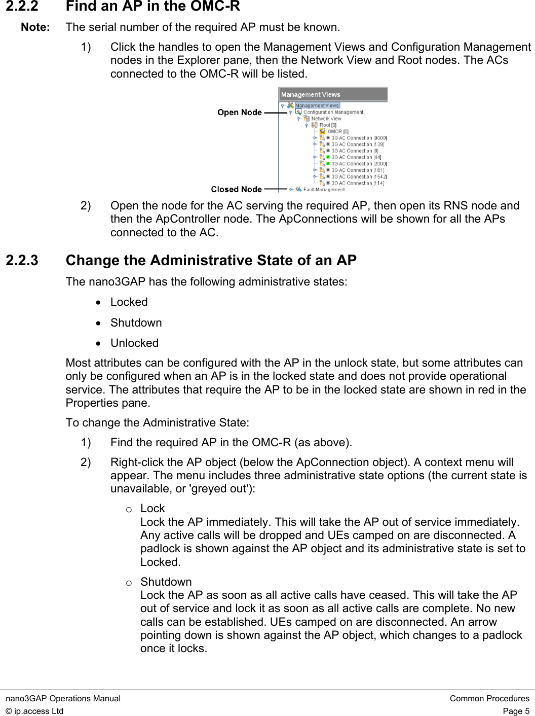
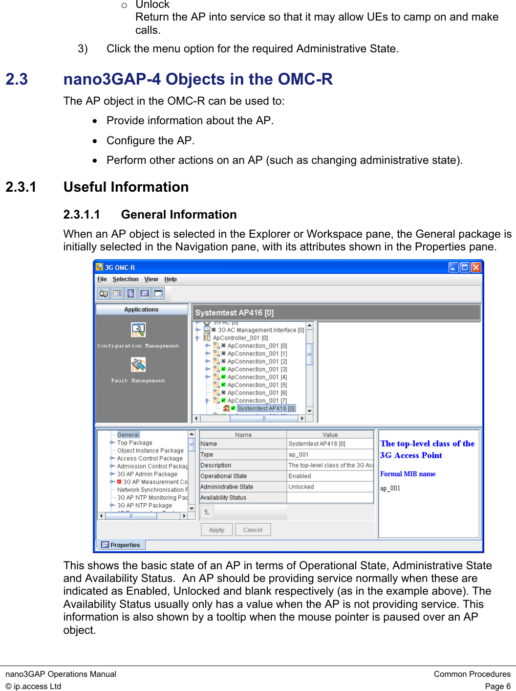
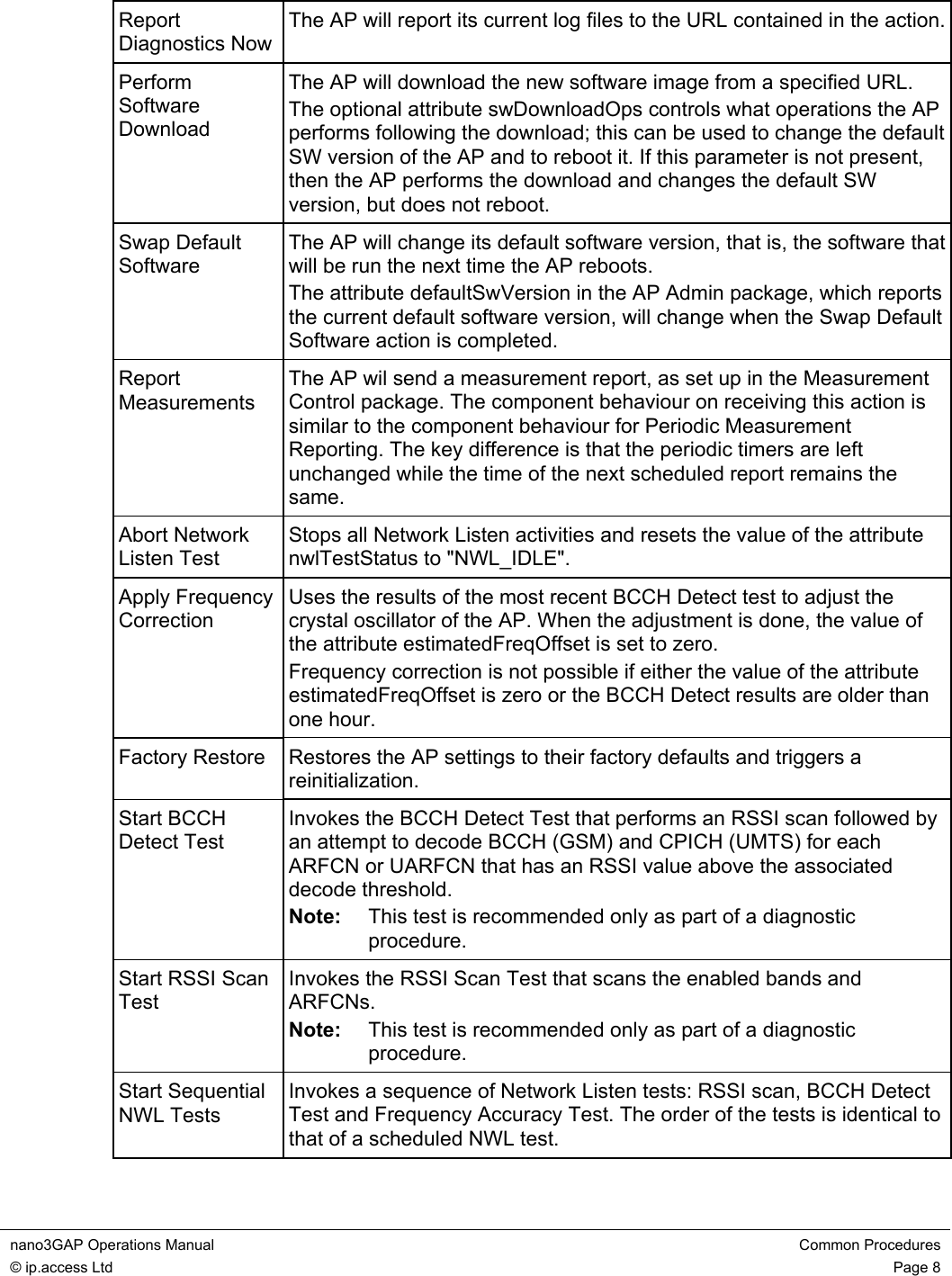
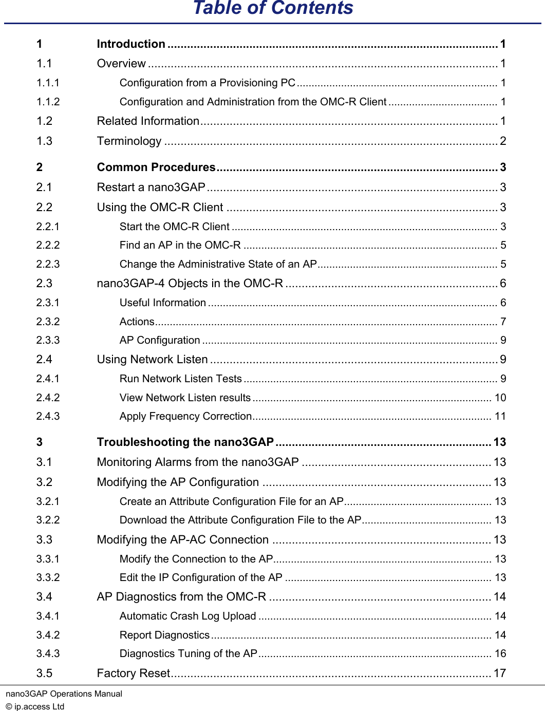
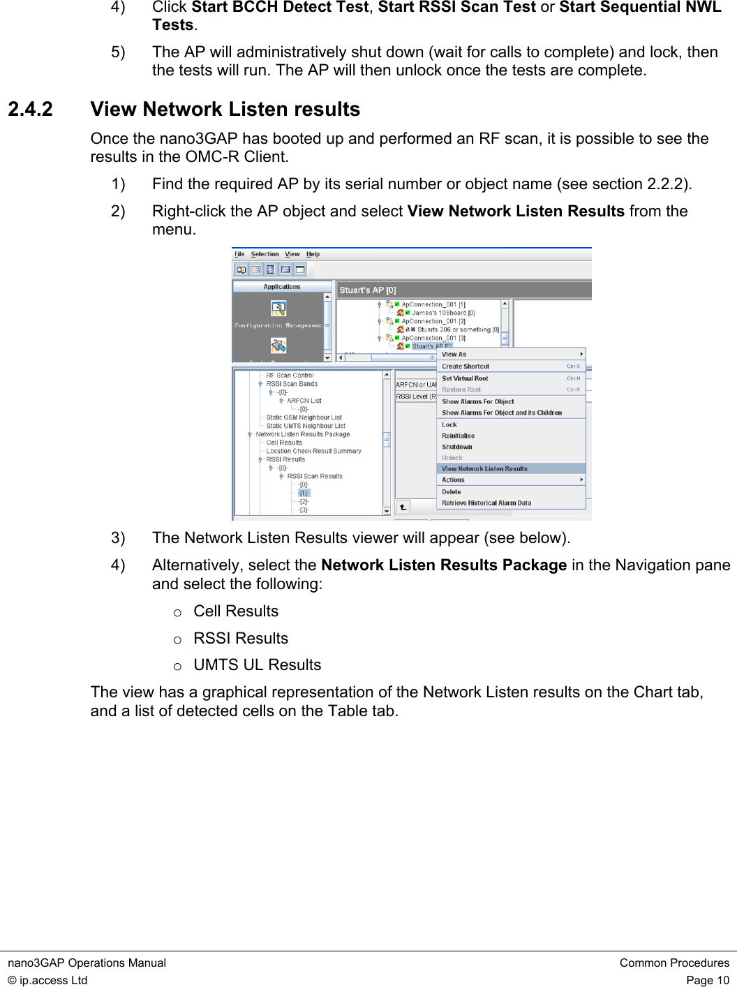
![nano3GAP Operations Manual Common Procedures © ip.access Ltd Page 9 Delete CRLs The AP will delete its CRLs. The currently open secure connections are not disconnected. The next time the AP attempts to open a secure connection, it has to connect to the CRL server to get an up-to-date CRL. 2.3.3 AP Configuration The essential configuration steps for commissioning an AP using the OMC-R are described in [INST_300]. This section provides additional information about configuration changes that may be of interest. • Network Listen Control Package • Cell Package • NAS Package • Location Package 2.4 Using Network Listen Network Listen (NWL) is used by a nano3GAP to scan the local RF environment and gather information from neighbouring cells. Network Listen can detect WCDMA cells, both macro and other nano3G and GSM cells. The AP can use the information gathered for the following: • Check neighbour cells for handover and reselection • Automatic clock frequency calibration 2.4.1 Run Network Listen Tests 1) Find the required AP by its serial number or object name (see section 2.2.2). 2) Right-click the AP object and a menu will appear. 3) Move the pointer down to Actions and a sub-menu will appear.](https://usermanual.wiki/ip-access/IPA219C.Operating-guide/User-Guide-1169424-Page-12.png)
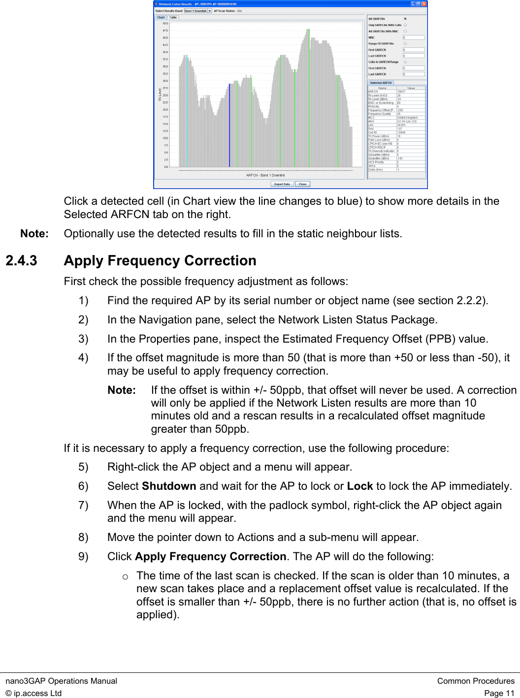
![nano3GAP Operations Manual Troubleshooting the nano3GAP © ip.access Ltd Page 13 3 Troubleshooting the nano3GAP 3.1 Monitoring Alarms from the nano3GAP For instructions see [OPM_410]. For information on the alarms, see [REF_130]. 3.2 Modifying the AP Configuration 3.2.1 Create an Attribute Configuration File for an AP The properties of the AP can be set from the OMC-R. Optionally, attributes can be imported from a text file. For the description of the text file format and for instructions on how to use it, see [INST_300]. 3.2.2 Download the Attribute Configuration File to the AP For instructions, see [INST_300]. 3.3 Modifying the AP-AC Connection The configuration of a nano3GAP can be modified in a web interface from the provisioning PC. The AP-AC connection and the IP configuration of the AP can be managed this way. The web interface is only enabled by default during commissioning when the AP is in factory reset state. To enable the web interface, the nano3GAP needs to be put into factory reset state (see section 3.5). 1) Start a web browser and go to the following address: http://192.168.0.1:8089/ 2) Enter the username and password. 3.3.1 Modify the Connection to the AP For instructions, see [INST_300]. 3.3.2 Edit the IP Configuration of the AP For instructions, see [INST_300].](https://usermanual.wiki/ip-access/IPA219C.Operating-guide/User-Guide-1169424-Page-16.png)
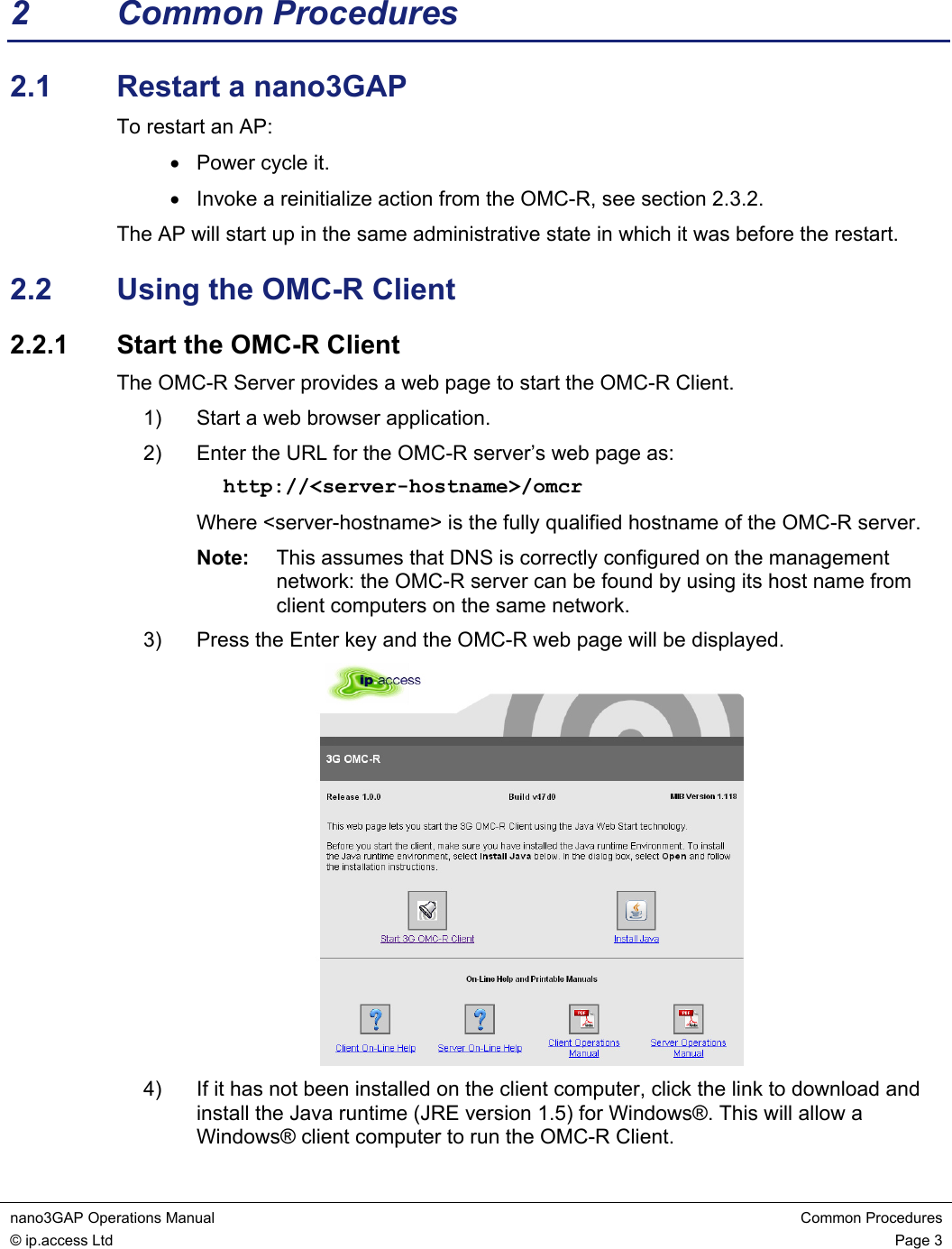
![nano3GAP Operations Manual Troubleshooting the nano3GAP © ip.access Ltd Page 17 3.5 Factory Reset Factory reset can be used when there are no ways to repair the AP-AC connection. The AP configuration needs to be redone manually after the factory reset, see [INST_300]. To perform factory reset, press the factory reset button and hold it for more than 5 seconds. When the button is initially pressed, the LED will blink fast (50ms on:50ms off) for 5 seconds, then it will start to blink slowly (200ms on: 200ms off). When the factory restore process has completed, the LED will extinguish and the AP will automatically reboot, take the fixed IP address and enable the web interface for configuration section 3.3.2.](https://usermanual.wiki/ip-access/IPA219C.Operating-guide/User-Guide-1169424-Page-20.png)