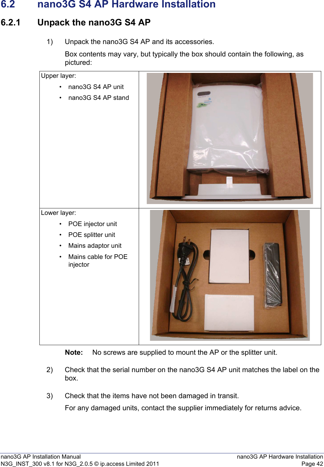
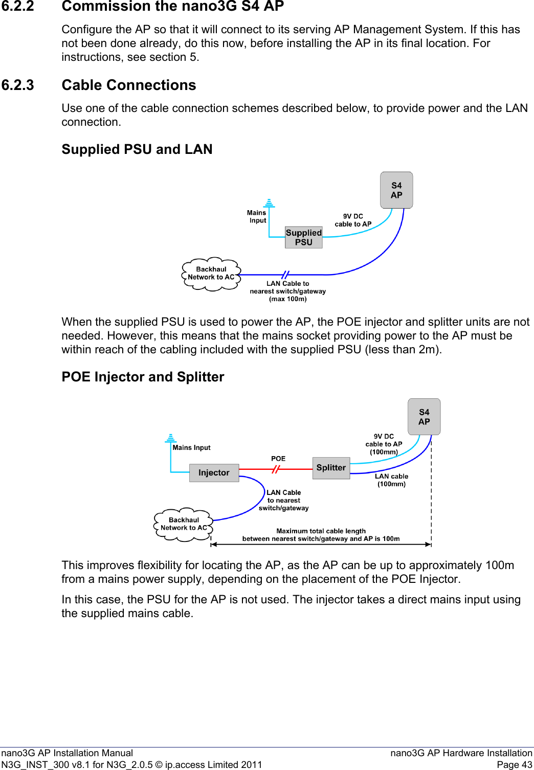
ip access IPA237C 8 user 3G Access Point operating at UMTS Band 4 User Manual N3G INST 300 AP Install v8 1
ip.access ltd 8 user 3G Access Point operating at UMTS Band 4 N3G INST 300 AP Install v8 1
UserManual.wiki
>
ip access
>
IPA237C User Manual
User manual
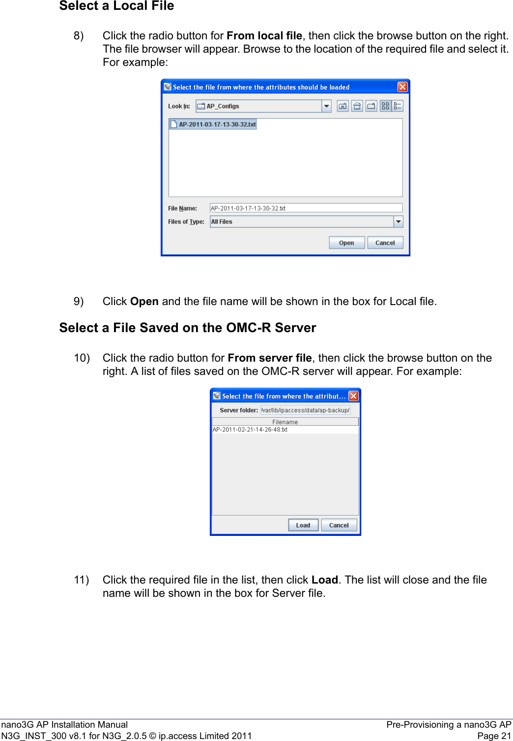
Navigation menu
Upload a User Manual
Namespaces
Wiki Guide
HTML
PDF
Info
Views
User Manual
Discussion / Help
Navigation
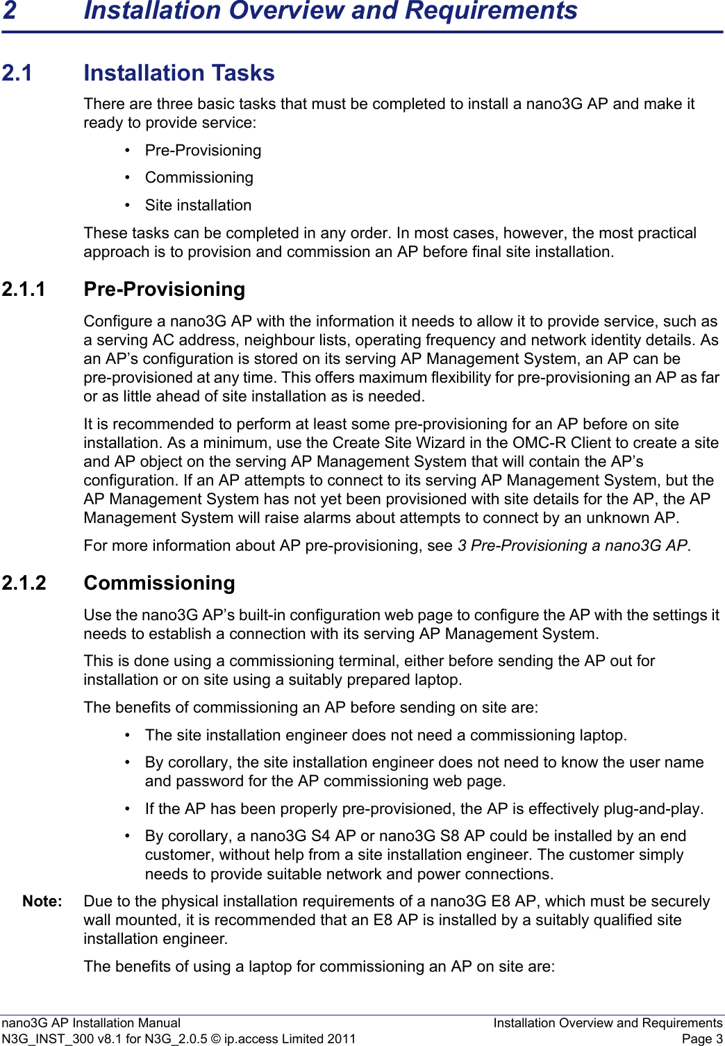
![nano3G AP Installation Manual IntroductionN3G_INST_300 v8.1 for N3G_2.0.5 © ip.access Limited 2011 Page 11 IntroductionThe ip.access nano3G AP is an indoor Access Point for enterprise applications.This manual provides all the necessary information required to install an ip.access nano3G AP. The manual provides step-by-step instructions for hardware installation and configuration steps required to bring a nano3G AP into service.The AP can be configured with a static IP address or it can obtain an IP address dynamically via DHCP. The AP-AC connection can be configured to be secure (via IPSec and a security gateway) or unsecured.1.1 OverviewThis manual is organised as follows:• AP installation requirements• AP configuration preparation• AP hardware installation• Commissioning configuration, for initial connection to an AC• Configuration from the OMC-R• Installation troubleshooting• Regulatory warnings and safety information• Supplementary information on licensing1.2 User RequirementsIt is assumed that any readers that will use the OMC-R Client already know how to:• Start the OMC-R Client• Navigate the Explorer Pane to find an AP object Refer to [OPM_410] for information on using the OMC-R Client.](https://usermanual.wiki/ip-access/IPA237C/User-Guide-1470788-Page-6.png)
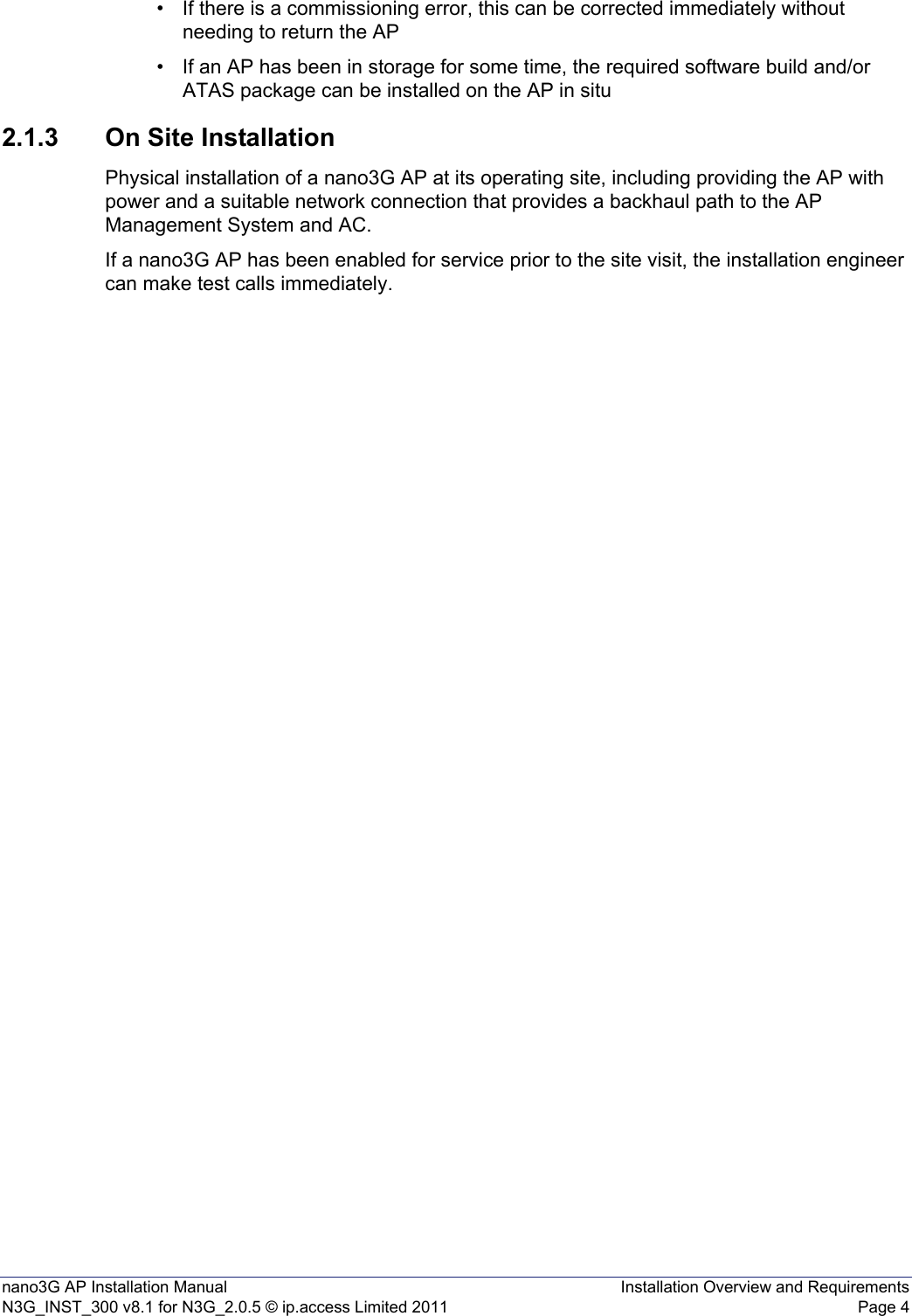
![nano3G AP Installation Manual IntroductionN3G_INST_300 v8.1 for N3G_2.0.5 © ip.access Limited 2011 Page 21.3 Related Information1.4 Licenses and Copyright NoticesPortions of the AP are constructed from third-party software and open source code and ip.access ltd gratefully acknowledges the contributions that these libraries, technologies and components have made to the product. Each of these is supplied under the terms of a license agreement and these are either reproduced or referenced in [REF_300], in line with the stipulations of their authors.1.5 TerminologyCommon nano3G System terminology is defined in [REF_105].For additional 3G terminology, see [21.905].[INST_440] nano3G AP Management System Installation Manual (N3G_INST_430)[OPM_300] nano3G AP Operations Manual (N3G_OPM_300)[OPM_410] 3G OMC-R Client Operations Manual (N3G_OPM_410)[OPM_440] nano3G AP Management System Operations Manual (N3G_OPM_440)[REF_105] nano3G System Glossary (N3G_REF_105)[REF_110] nano3G System Configuration Management (CM) MIB Reference Manual (N3G_REF_110)[REF_300] nano3G AP License and Copyright Reference (N3G_REF_300)[21.905] Vocabulary for 3GPP Specifications (3GPP 3G TR 21.905)](https://usermanual.wiki/ip-access/IPA237C/User-Guide-1470788-Page-7.png)
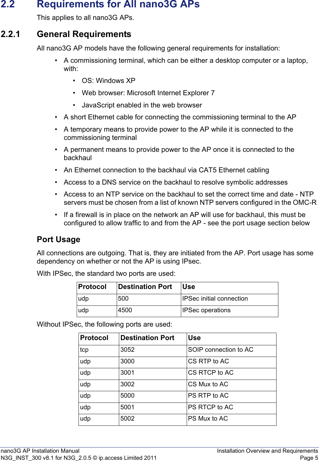
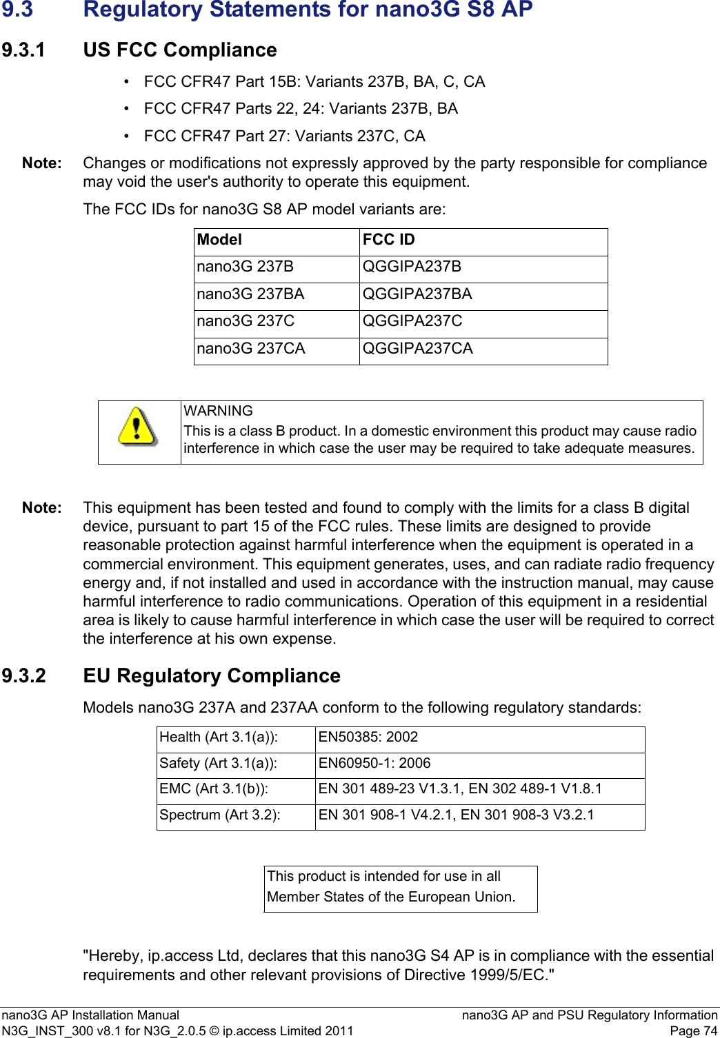
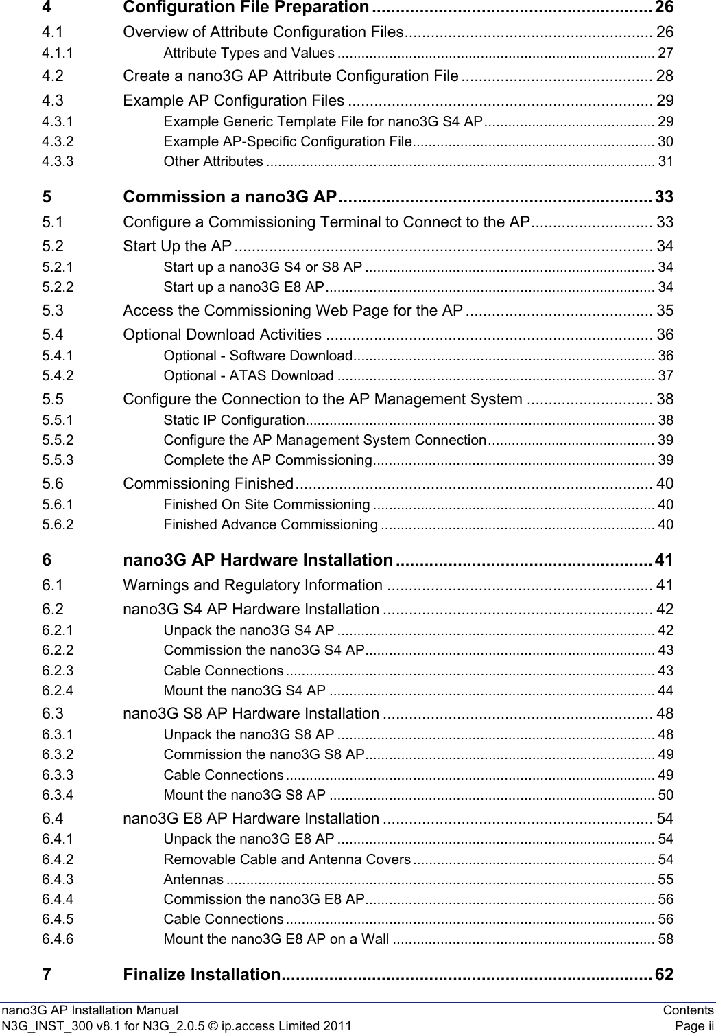
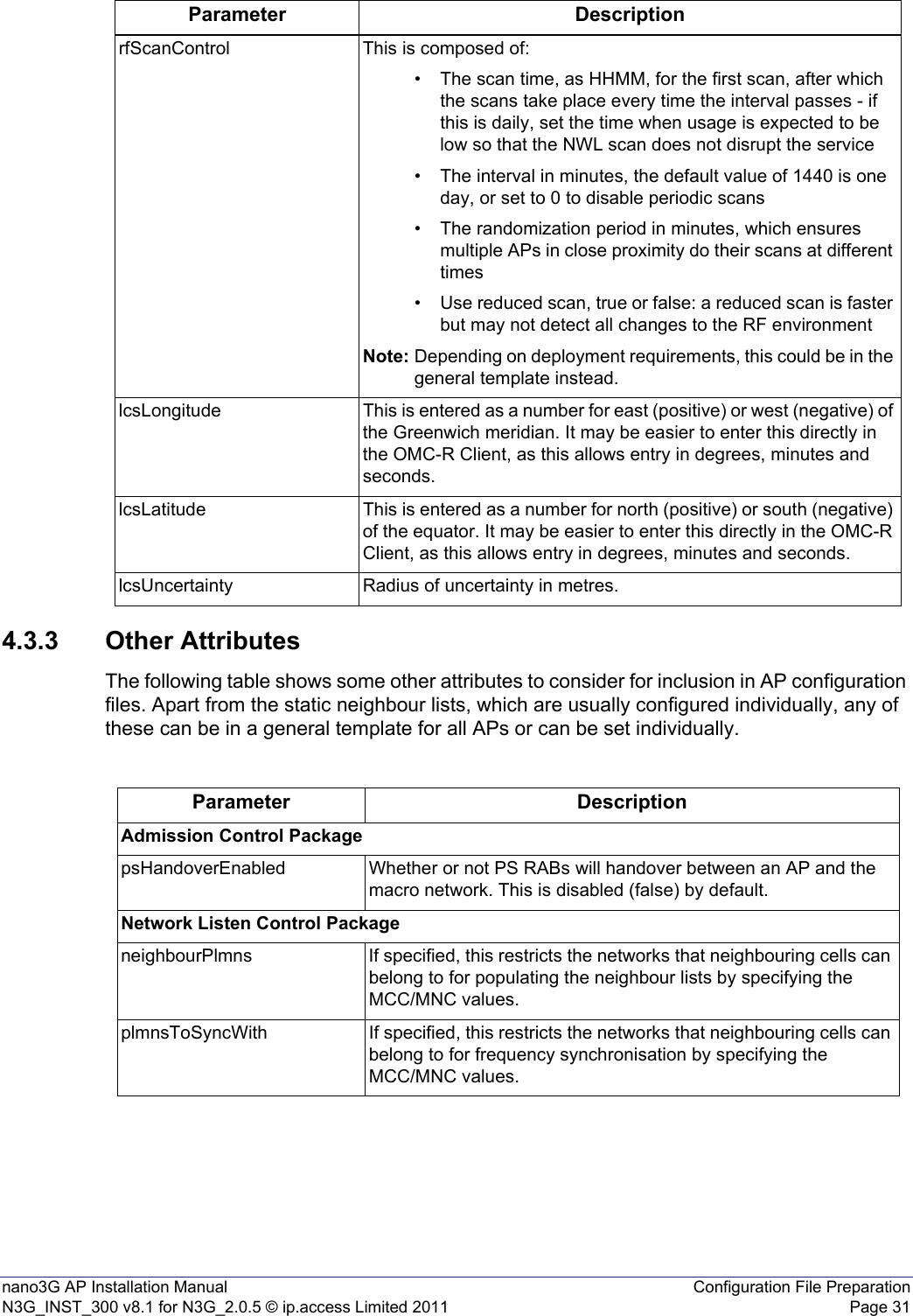
![nano3G AP Installation Manual Installation Overview and RequirementsN3G_INST_300 v8.1 for N3G_2.0.5 © ip.access Limited 2011 Page 6The following ports are also used. When IPsec is used, they may be inside or outside the IPSec tunnel, depending on configuration:2.2.2 Information Required for Pre-ProvisioningAll nano3G AP models require the configuration details listed in this section. This information will be used to configure an AP from the OMC-R Client, typically by a NOC engineer. • User name and password for the OMC-R Client. To be able to configure an AP from the OMC-R Client, the user name must have Full Access to the AP Management System serving the AP and Full Access granted to its APs. See [OPM_410] for full details about user permissions.• The minimum set of configuration data for the AP is:• Cell ID (also used as the ID of this AP on the serving nano3G AC)• IP Address or FQDN of the serving AC• MCC •MNC•LAC•RAC•SAI SAC•SAI LAC•UARFCN• Scrambling code• RNC ID• RSSI scan bands• Latitude and longitude of the APs installation site, for RANAP location reporting• Additional configuration that may be required includes:• Static neighbour list - see [OPM_300] for neighbour list configuration• URLs for the PM reporting and diagnostic services on the AP Management SystemNote: It is possible to configure an AP before taking it on site. Protocol Destination Port Usetcp 80 PM upload, software download, CRL downloadtcp 443 PM upload, software download, CRL downloadudp 53 DNSudp 67 DHCP - not needed for static IP configurationudp 68 DHCP - not needed for static IP configurationudp 123 NTP](https://usermanual.wiki/ip-access/IPA237C/User-Guide-1470788-Page-11.png)

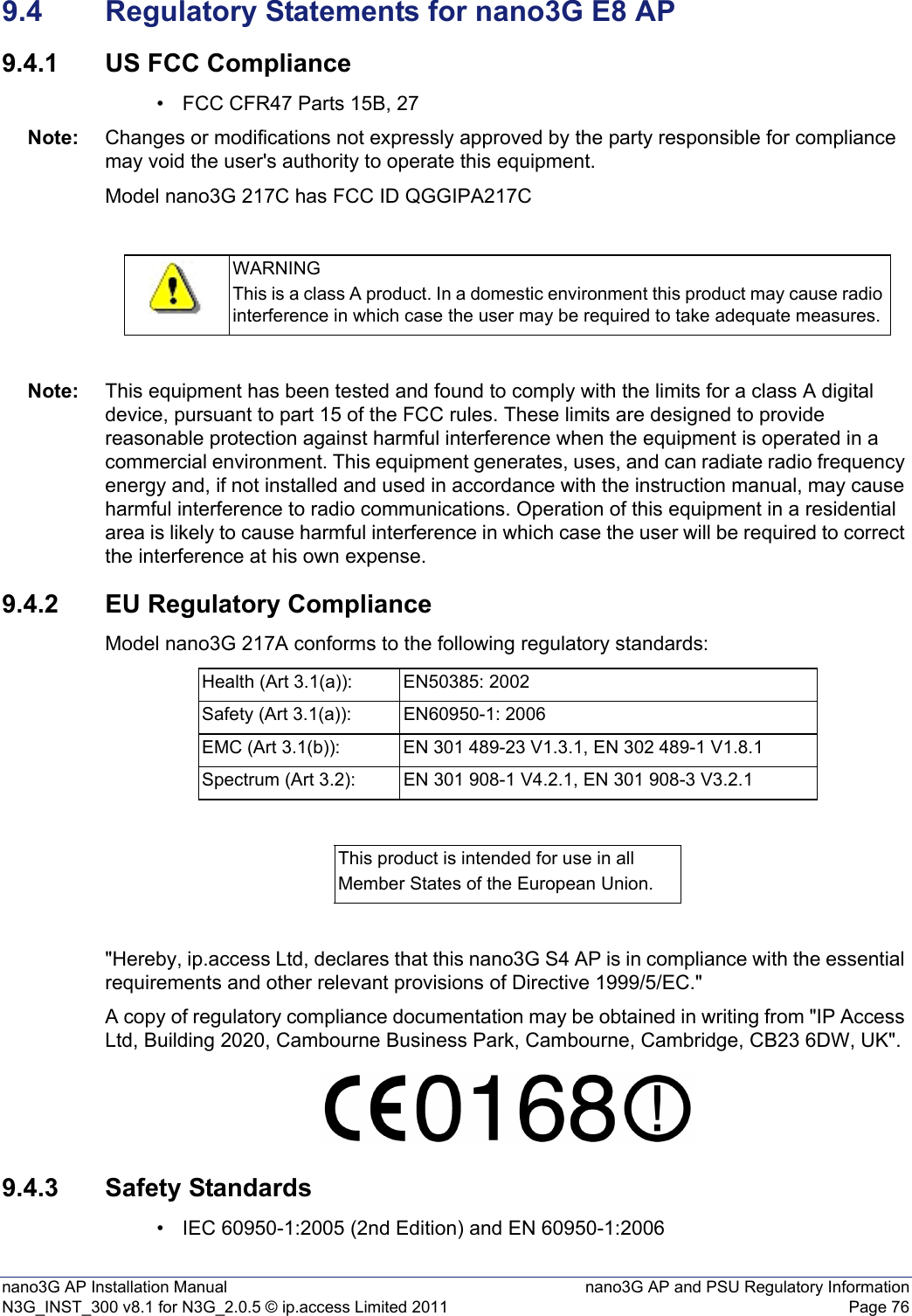
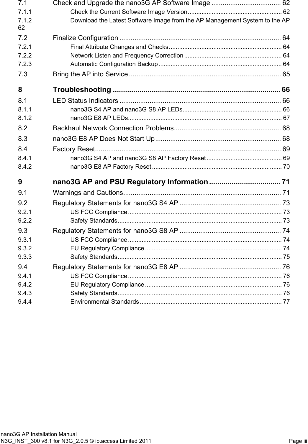
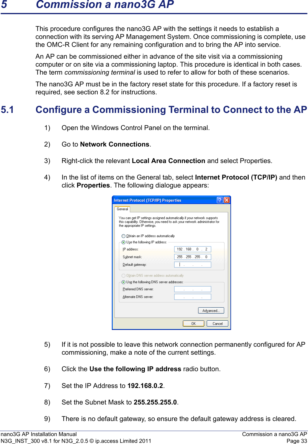
![nano3G AP Installation Manual Configuration File PreparationN3G_INST_300 v8.1 for N3G_2.0.5 © ip.access Limited 2011 Page 27When using the ObjectInstance value, it must be reproduced exactly or the configuration file will not load against the target AP. A way around this is to save a configuration file for that AP, regardless of its configuration state, then copy and paste the ObjectInstance into the file that has the correct configuration. Note: All of the attributes can be configured from the OMC-R Client. After initial provisioning from a configuration file the OMC-R Client can be used to set attributes or the configuration file can be edited to set more parameters, for example when using configuration information from a radio planning system. To obtain a sample file with all the attributes that can be configured, export a configuration file as described in section 4.2 and inspect its content.4.1.1 Attribute Types and ValuesThe attribute types and values conform to the attribute definitions in the MIB. See [REF_110] for a full description of each object type, the attributes it may contain and the valid values that may be assigned to each attribute.The following attribute types are available, which are also formally described in [REF_110]: • Base types:• Integer - a whole number numeric value, often must be within a range of valid valuestos=0• Enumeration, or enum - a value name from a pre-defined set of names with specific valuest300=T300_4000_MSEC• Boolean - a true or false valuesoipHeartbeatEnabled=true• String - a value enclosed in double-quotes (the double-quote character itself cannot be part of the value)mnc="12"• Compound types that are made of multiple instances of any types:• Array - a comma delimited set of values of the same type within square brackets [ ]ascPersistenceScalingFactors=[6,6,6,6,6,6]• Structure - a comma delimited set of values within curly brackets { }, and each value can be of any type cellBroadcastMessage={50,GSM_DEFAULT,"nano3G"}• Set - similar to an array, this a comma delimited set of values of the same type within round brackets ( ), however, each value must be different rfParamsCandidateList=({1062,437,1})Note: In the OMC-R Client, the compound types are the complex attributes that have multiple levels within the Navigation and Properties panes.Note: In [REF_110], there is a distinction between expert and non-expert attributes. As a general rule, it is recommended to leave expert attributes at their default values.](https://usermanual.wiki/ip-access/IPA237C/User-Guide-1470788-Page-32.png)
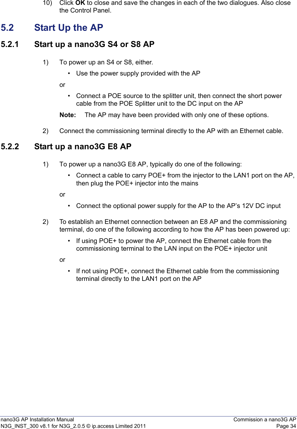
![nano3G AP Installation Manual Configuration File PreparationN3G_INST_300 v8.1 for N3G_2.0.5 © ip.access Limited 2011 Page 284.2 Create a nano3G AP Attribute Configuration FileA file can be created from scratch in a text editor, or can be started from the configuration of an existing AP. To create a configuration file from scratch, simply open a text editor and enter the required configuration details.For information on the syntax of the configuration file, see section 4.1. For example configuration files, see section 4.3.To start a configuration file by saving the configuration of an existing AP:1) Start an OMC-R Client session.Note: For full information on using the OMC-R Client, see [OPM_410].2) In the Explorer pane of the OMC-R Client, find and select a suitable 3G AP object to use as a template. That is, select an AP of the same type as the target AP. 3) Right-click on the AP object and select Save Attributes to File. The Save Attributes Wizard will appear.4) Select the radio button for the required location. For the purposes of creating a template for another AP, saving To Local File is recommended.When saving To Local File, the target directory and file name may be changed.When saving To Server File (on the OMC-R Server), the directory and file name are set automatically and cannot be changed. The file is named as follows: AP-<Serial_number>-<Object_name>-<Date_Time>.txtWhere the <Serial_number> for the AP ensures the file name is unique, the <Object_name> can make individual APs easier to identify and the <Date_Time> is the date and time the file was created.5) Click Finish to save the configuration file.The file will contain all writable attributes. That is, all attributes that can be changed from within the OMC-R Client. Most of these will be at default values. 6) Edit the file in a suitable text editor, and adjust the configuration as needed for the new AP, or any number of new APs. If the file will be used as a general template that will be loaded on multiple APs, remove the ObjectInstance= line from the file.Note: Use a text editor that can edit Unix text files. Windows® WordPad can be used, but Notepad is not suitable.](https://usermanual.wiki/ip-access/IPA237C/User-Guide-1470788-Page-33.png)
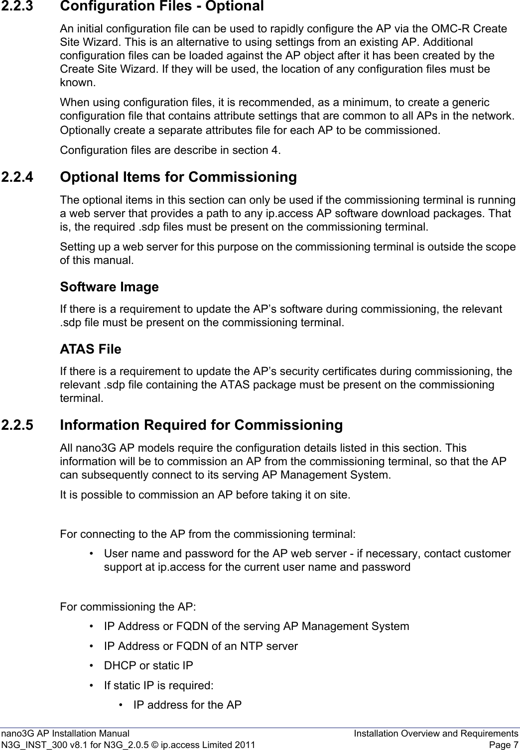
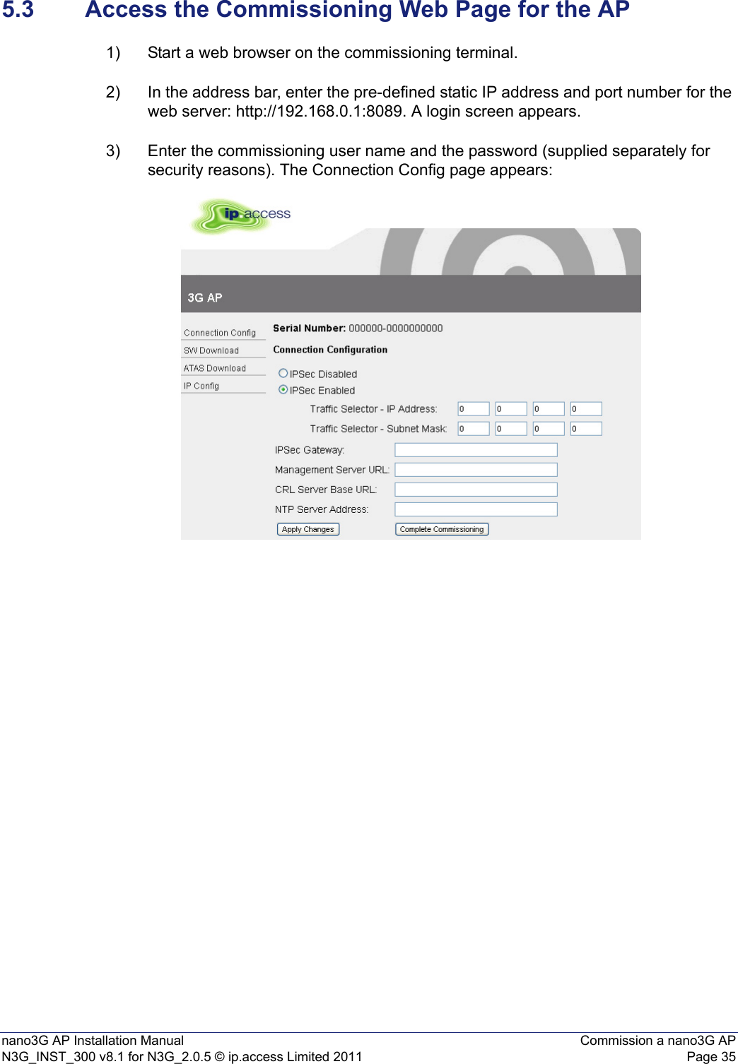
![nano3G AP Installation Manual Configuration File PreparationN3G_INST_300 v8.1 for N3G_2.0.5 © ip.access Limited 2011 Page 32staticGsmNeighbourList This is a complex attribute that specifies GSM (2G) neighbour candidates. It is recommended to enter these directly in the OMC-R Client. However, if a similar list has already been configured for a nearby AP, it may be advantageous to copy this attribute from a configuration file saved from the nearby AP, load this into the target AP and then make suitable adjustments from the OMC-R Client.See [OPM_300] for information on neighbour list configuration. staticUmtsNeighbourList This is a complex attribute that specifies UMTS (3G) neighbour candidates. It is recommended to enter these directly in the OMC-R Client. However, if a similar list has already been configured for a nearby AP, it may be advantageous to copy this attribute from a configuration file saved from the nearby AP, load this into the target AP and then make suitable adjustments from the OMC-R Client.See [OPM_300] for information on neighbour list configuration. Oscillator Synchronisation PackageoscillatorSynchronisationTimeoutThe number of days an AP can go without resynchronisation before it raises the relevant alarm. Parameter Description](https://usermanual.wiki/ip-access/IPA237C/User-Guide-1470788-Page-37.png)


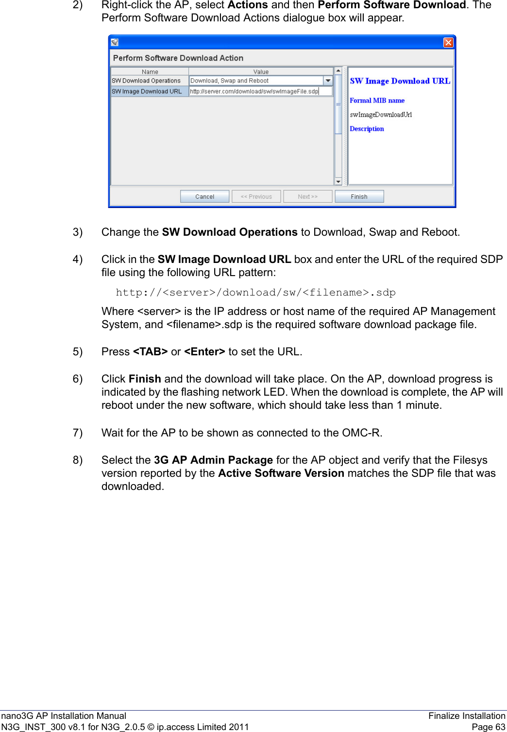
![nano3G AP Installation Manual Finalize InstallationN3G_INST_300 v8.1 for N3G_2.0.5 © ip.access Limited 2011 Page 627 Finalize InstallationAll the activities in this section are managed from the OMC-R Client.7.1 Check and Upgrade the nano3G AP Software ImageThis is a useful check to ensure that the AP has the required software version, even if the AP software was recently updated during commissioning. 7.1.1 Check the Current Software Image Version1) Login to the OMC-R Client with a user name (and password) that has Full Access rights for changing the AP's configuration.2) Find the AP according to its Site and select the AP object. Note: For full information on using the OMC-R Client, see [OPM_410].3) Verify that the Site has a green tick, to show that the AP is connected to the AP Management System. The AP object, below the Site, may be currently locked. The AP will remain locked if it is not ready to provide service. 4) In the Navigation pane, browse to the AP Admin Package.5) Check the values of the Active SW Version and Standby SW Version attributes.6) If the AP does not have the latest software image, download it to the AP from the AP Management System according to the instructions below.7.1.2 Download the Latest Software Image from the AP Management System to the APFor instructions about how the software images (SDP files) are uploaded to the AP Management System, see [OPM_440].1) Select the AP in the OMC-R Client.](https://usermanual.wiki/ip-access/IPA237C/User-Guide-1470788-Page-67.png)
![nano3G AP Installation Manual Finalize InstallationN3G_INST_300 v8.1 for N3G_2.0.5 © ip.access Limited 2011 Page 647.2 Finalize Configuration1) Login to the OMC-R Client with a user name that has Full Access to the required AP.7.2.1 Final Attribute Changes and Checks2) Make any AP-specific configuration changes that have not already been applied by the Create Site Wizard or loading configuration files. In particular, ensure the static neighbour lists are correctly configured. See [OPM_300] for information on neighbour list configuration. 3) Spot check any or all of the following packages to verify the attributes are set to the correct values:• Cell Package•NAS Package• Location Package7.2.2 Network Listen and Frequency Correction4) To execute a Network Listen scan, right-click the AP object, select Actions and then select Start Sequential NWL Scan. 5) When the scan is complete, view the results and verify there is some radio activity detected, and ideally some neighbour cells. This will confirm the radio is working.6) Only if a suitable macro neighbour has been detected, a correction can be applied to ensure that the oscillator frequency is correct. Select Actions and then select Apply Frequency Correction.Note: Assuming there is a suitable macro neighbour, this should be repeated approximately 24 hours after the AP is brought into service. This will allow time for the oscillator crystal to stabilize, at which time the frequency correction should be re-applied. 7.2.3 Automatic Configuration BackupThe configuration of an AP is automatically backed up on the OMC-R server each time configuration changes are applied from the OMC-R Client. The configuration files are named according to the AP serial numbers. A file is overwritten automatically by subsequent configuration changes. The files are saved in: /var/lib/ipaccess/data/auto-ap-backup](https://usermanual.wiki/ip-access/IPA237C/User-Guide-1470788-Page-69.png)