ip access IPA239B 16 user 3G Access Point operating at UMTS Bands 2 & 5 User Manual N3G INST 300 AP Install v14 0
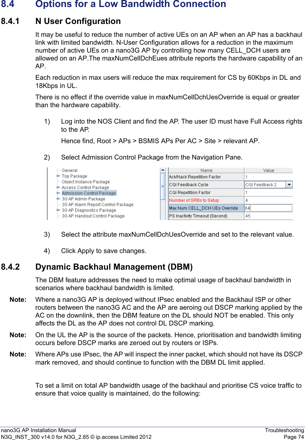
ip.access ltd 16 user 3G Access Point operating at UMTS Bands 2 & 5 N3G INST 300 AP Install v14 0
UserManual.wiki
>
ip access
>
IPA239B User Manual
Exhibit 08 Users Manual
Navigation menu
Upload a User Manual
Namespaces
Wiki Guide
HTML
PDF
Info
Views
User Manual
Discussion / Help
Navigation

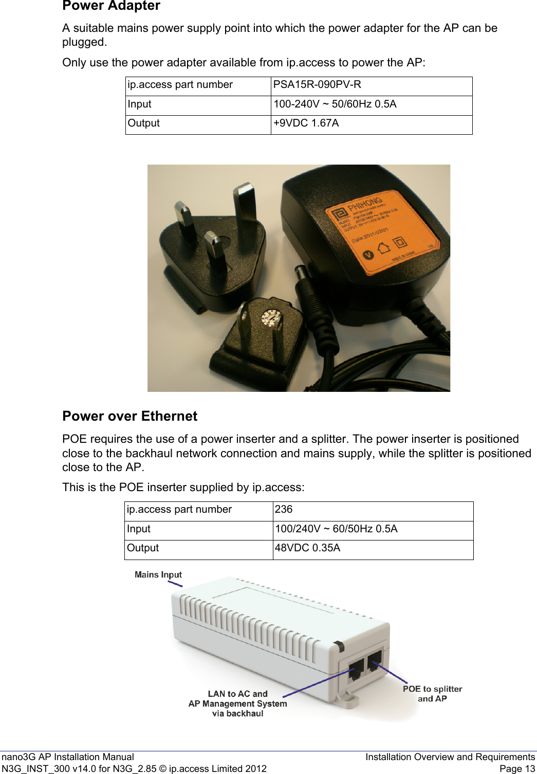
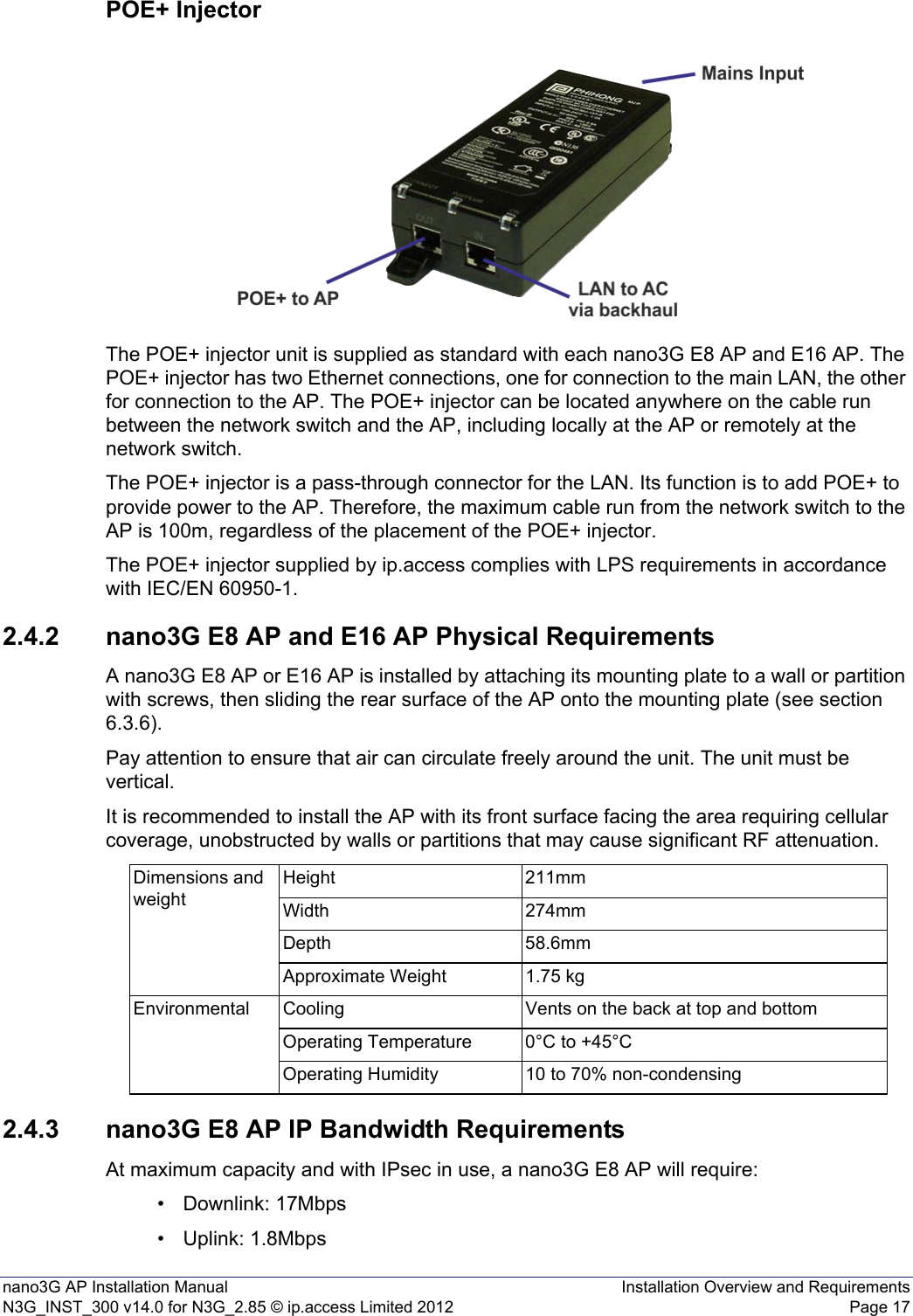
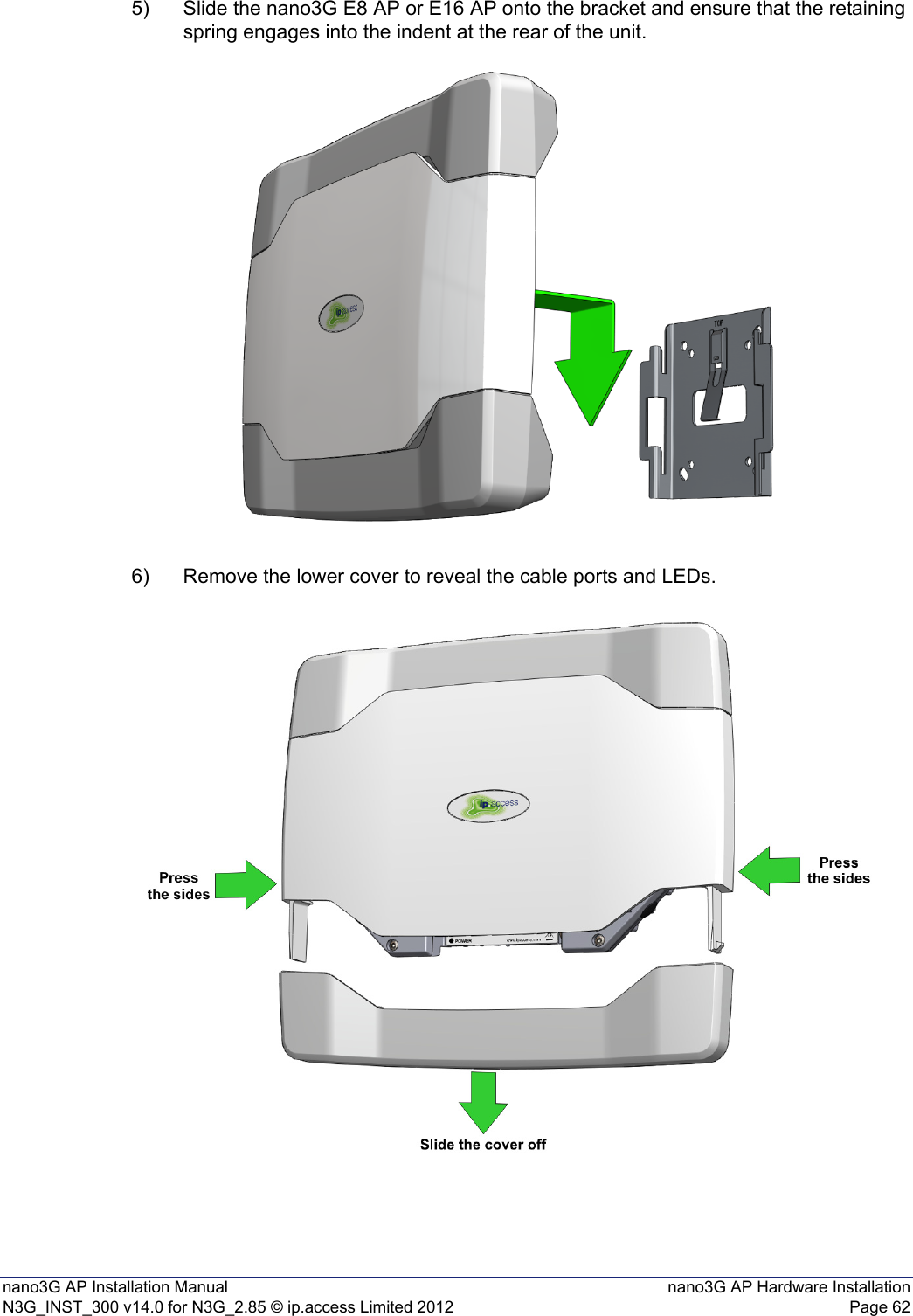
![nano3G AP Installation Manual IntroductionN3G_INST_300 v14.0 for N3G_2.85 © ip.access Limited 2012 Page 11 IntroductionThe ip.access nano3G AP is an indoor Access Point for enterprise applications.This manual provides all the necessary information required to install an ip.access nano3G AP. The manual provides step-by-step instructions for hardware installation and configuration steps required to bring a nano3G AP into service.The AP can be configured with a static IP address or it can obtain an IP address dynamically via DHCP. The AP-NOS Server and AP-AC connections can be configured to be secure (via IPSec and a security gateway) or unsecured.1.1 OverviewThis manual is organised as follows:• This introduction• An overview of AP installation, including installation requirements for all AP variants and specific requirements for each AP model • AP pre-provisioning in the NOS Server using the NOS Client• AP configuration file preparation - this is supplementary information for pre-provisioning• Commissioning an AP for connection to its serving NOS Server • AP hardware installation• Optional activities to finalize installation• Installation troubleshooting• Regulatory warnings and safety information1.2 User RequirementsIt is assumed that any readers that will use the NOS Client already know how to:• Start the NOS Client• Navigate the Explorer Pane to find an AP object It is also assumed that the any readers that will use the NOS Client will have suitable user privileges for the NOS Client. Refer to [OPM_415] for information on using the NOS Client.](https://usermanual.wiki/ip-access/IPA239B/User-Guide-1776045-Page-7.png)
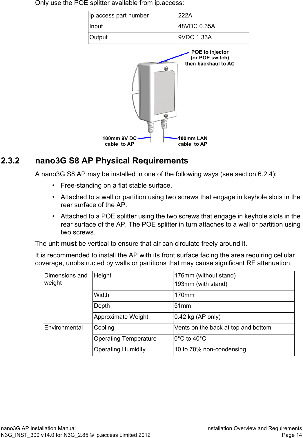
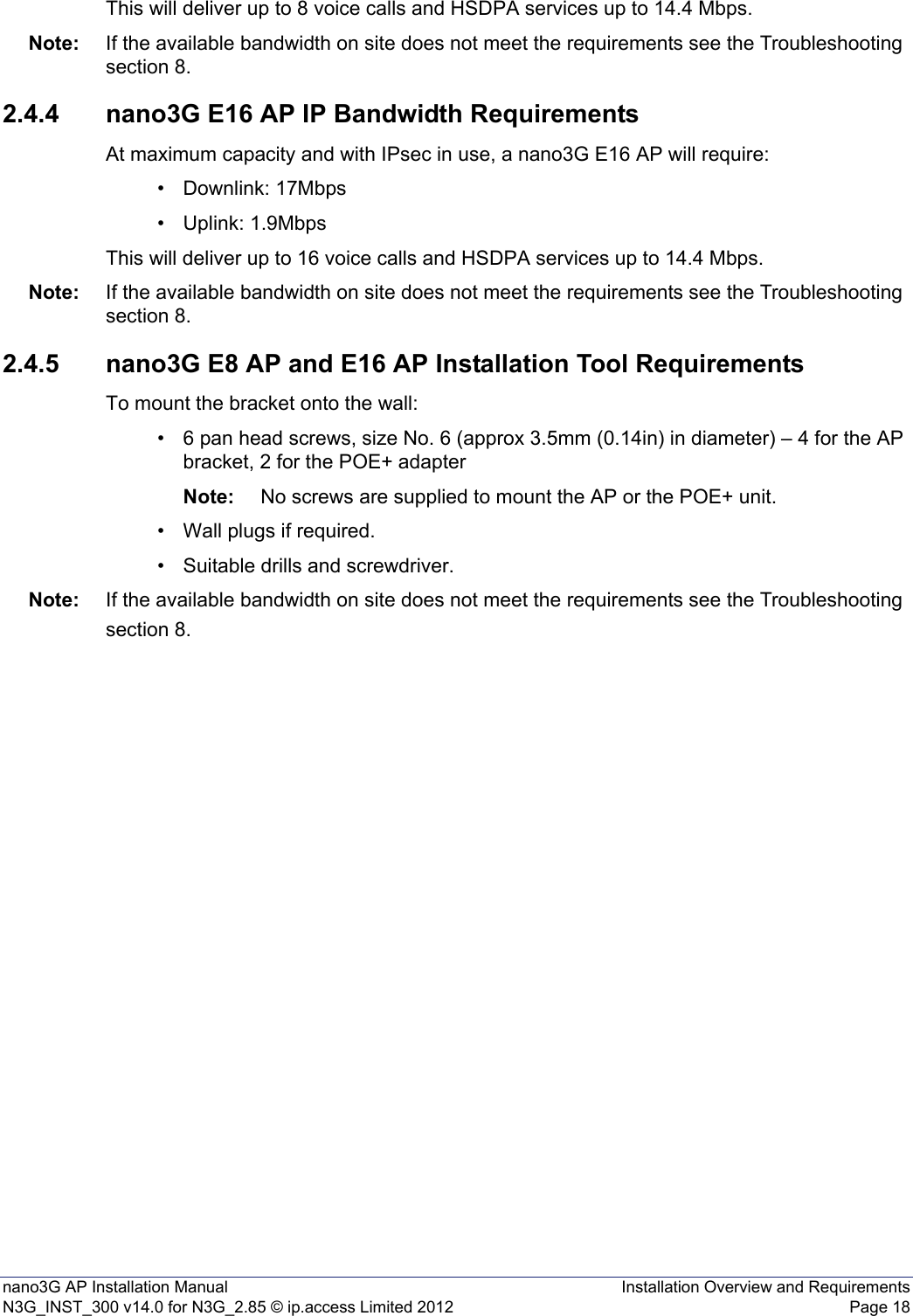
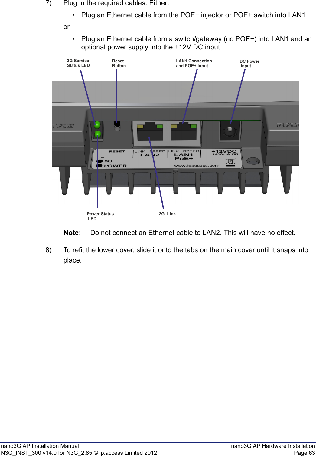
![nano3G AP Installation Manual IntroductionN3G_INST_300 v14.0 for N3G_2.85 © ip.access Limited 2012 Page 21.3 Related Information1.4 Licenses and Copyright NoticesPortions of the AP are constructed from third-party software and open source code and ip.access ltd gratefully acknowledges the contributions that these libraries, technologies and components have made to the product. Each of these is supplied under the terms of a license agreement and these are either reproduced or referenced in [REF_300], in line with the stipulations of their authors.1.5 TerminologyCommon nano3G System terminology is defined in [REF_105].For additional 3G terminology, see [21.905].[INST_440] nano3G NOS Server Installation Manual (N3G_INST_430)[OPM_300] nano3G AP Operations Manual (N3G_OPM_300)[OPM_415] NOS Client Operations Manual (N3G_OPM_415)[OPM_440] NOS Server Operations Manual (N3G_OPM_440)[REF_105] nano3G System Glossary (N3G_REF_105)[REF_110] nano3G System Configuration Management (CM) MIB Reference Manual (N3G_REF_110)[REF_300] nano3G AP License and Copyright Reference (N3G_REF_300)[TRB_300] nano3G AP Troubleshooting Manual (N3G_TRB_300)[21.905] Vocabulary for 3GPP Specifications (3GPP 3G TR 21.905)](https://usermanual.wiki/ip-access/IPA239B/User-Guide-1776045-Page-8.png)
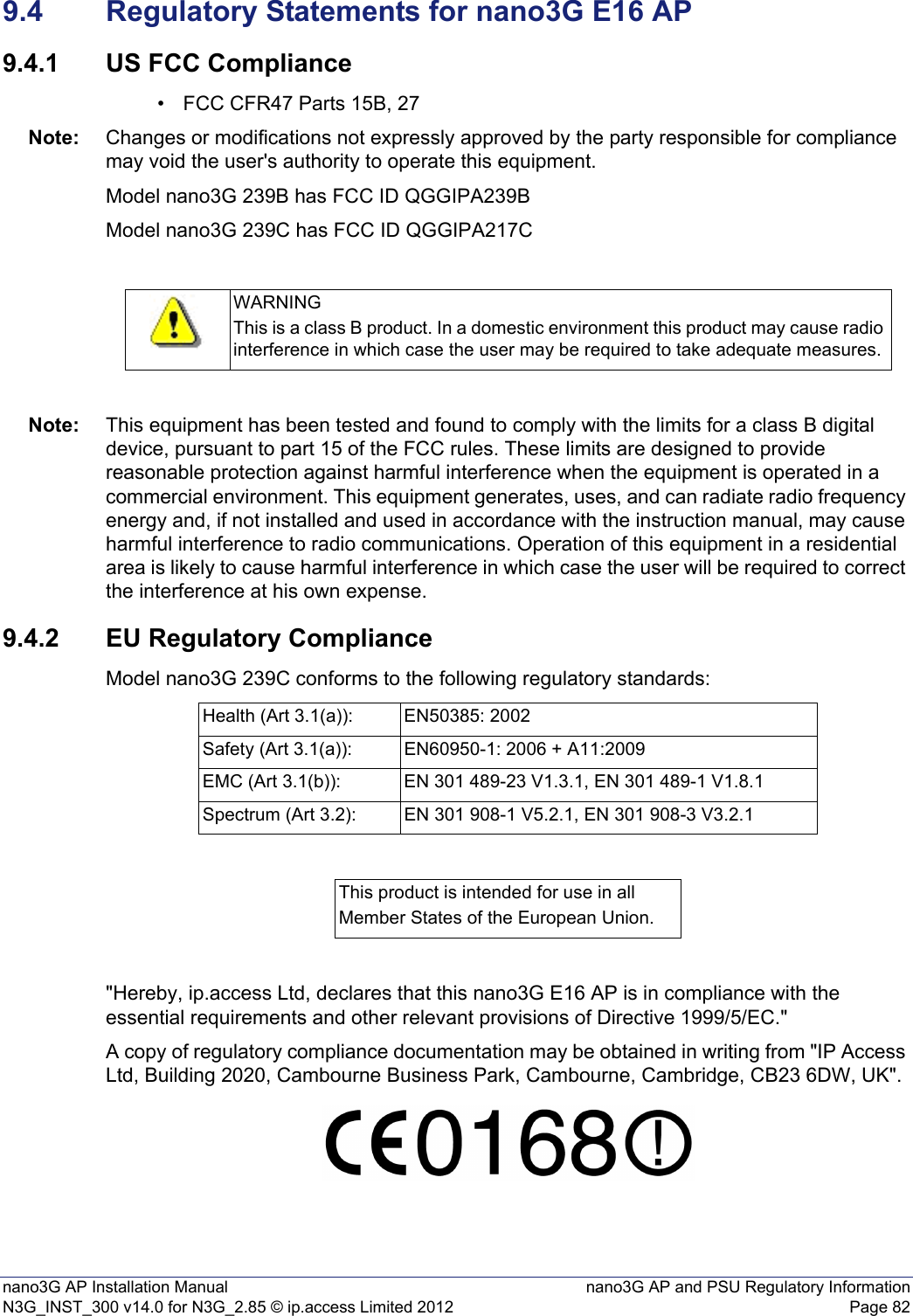
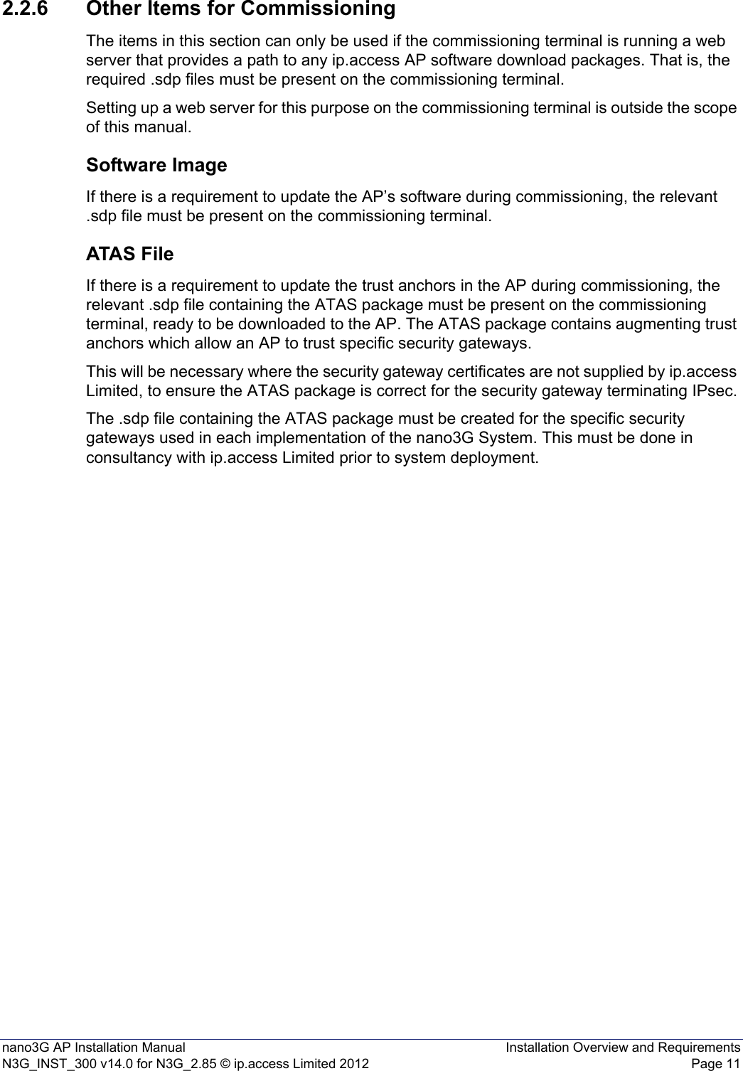
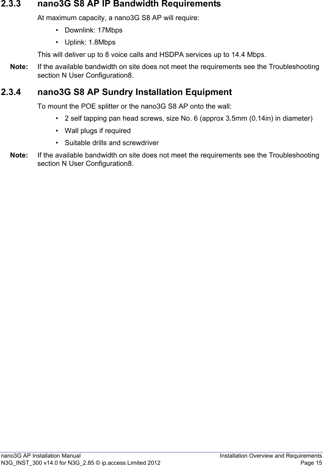
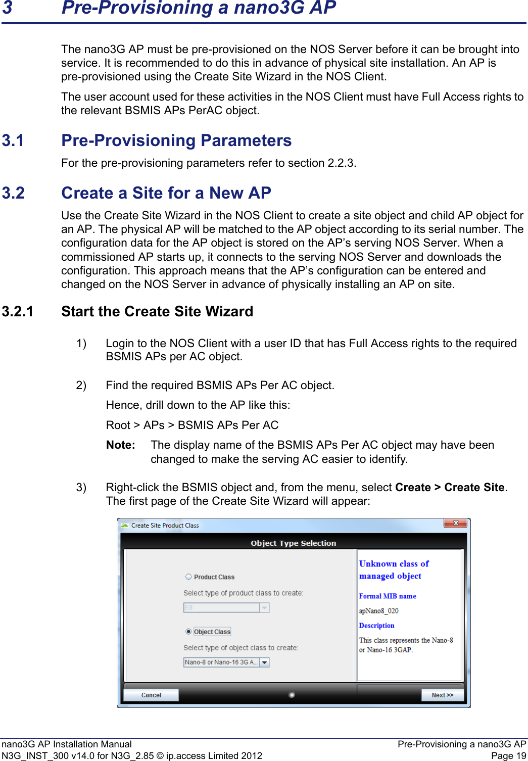
![nano3G AP Installation Manual Installation Overview and RequirementsN3G_INST_300 v14.0 for N3G_2.85 © ip.access Limited 2012 Page 6• When free-standing the nano3G S8 AP, the stand supplied for this purpose must be used, and the AP must be upright, as noted above. 2.2.3 Information Required for Pre-ProvisioningThis information will be used to configure an AP from the NOS Client. This is applicable to all nano3G AP models. Note: It is recommended to pre-provision an AP before taking it on site, so that the AP can download its configuration when it starts up on site. OMC-R Client Login DetailsUser name and password for the NOS Client. To be able to configure an AP from the NOS Client, the user name must have Full Access to the NOS Server serving the AP and Full Access granted to its APs. See [OPM_415] for full details about user permissions.Minimum ConfigurationThe minimum set of configuration data for the AP is:Parameter NotesHNB C-Id This is the unique ID of this AP on the serving nano3G AC. The term HNB is used in 3GPP in reference to small cells. The HNB C-Id is used in the Register Request message to uniquely identify the AP within the AC. The value is also combined with the RNC-ID to give the 28 bit UC-Id (also known as TR-196 CellID) that is used on-air in SIB3.RNC ID RNC ID of the AC - this is selected by choosing the AC Detail for the AP’s site.AC address IP Address or FQDN of the serving AC.MCC Mobile Country Code.MNC Mobile Network Code.LAC Location Area Code.RAC Routing Area Code.SAI SAC This is the SAI SAC (Service Access Code) which can be used by the billing system. If this is not used by the billing system, it is recommended to set this to 1.SAI LAC SAI Location Area Code which can be used by the billing system. This is a different value than the LAC set in the lacRacCandidateList for an individual AP. If this is not used by the billing system, it is recommended to set this to 1. UARFCN The frequency on which the AP will operate. This should be determined by network planning.Scrambling code The scrambling code assigned to the AP. This should be determined by network planning.RSSI scan bands Specify which bands to scan with Network Listen, when performing RSSI detect and BCCH decode tests. Leave this empty to scan all bands supported by the AP hardware. Lat, Long and LCS uncertainty Latitude and longitude of the APs installation site, for RANAP location reporting](https://usermanual.wiki/ip-access/IPA239B/User-Guide-1776045-Page-12.png)
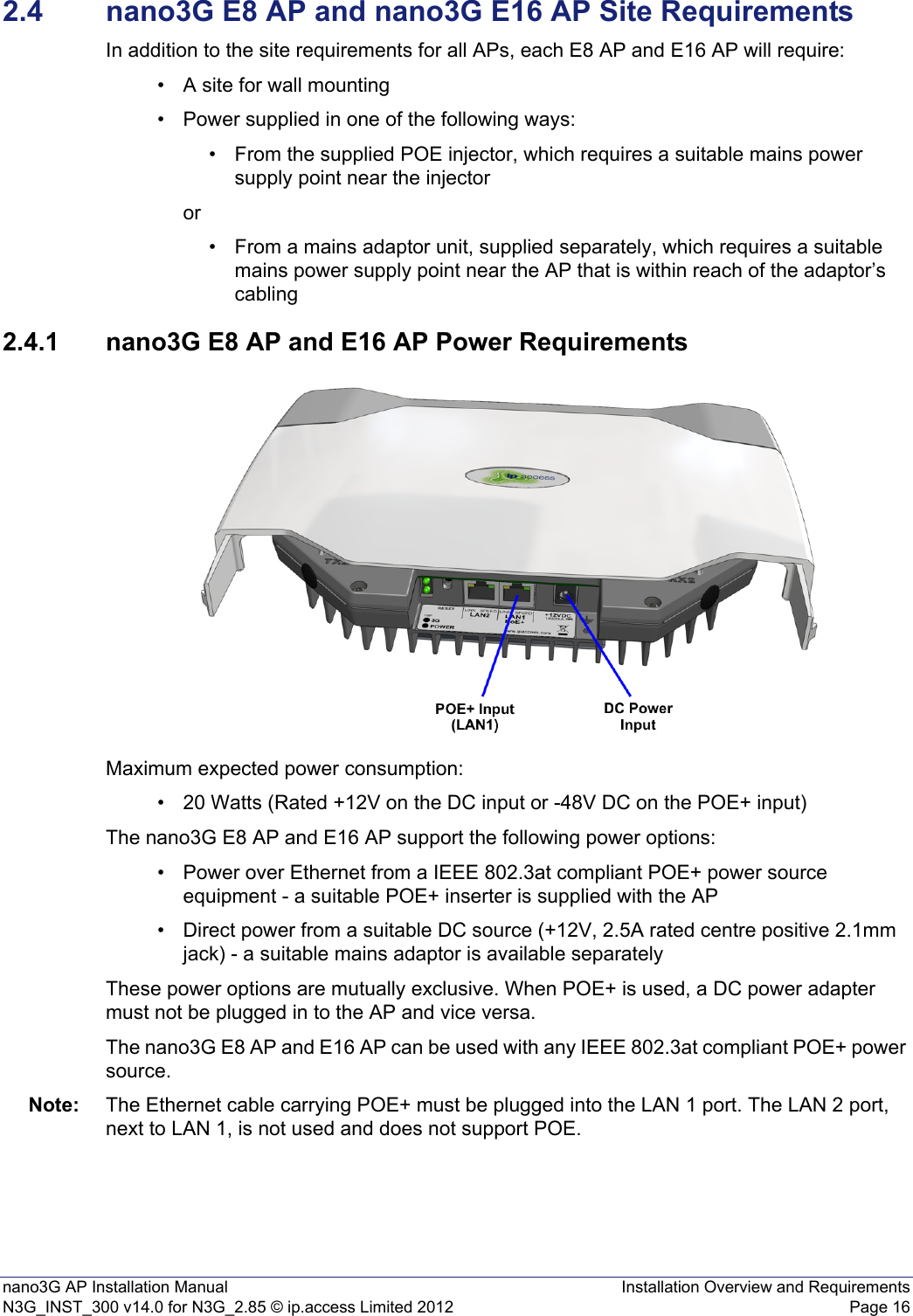
![nano3G AP Installation Manual Installation Overview and RequirementsN3G_INST_300 v14.0 for N3G_2.85 © ip.access Limited 2012 Page 7Other AttributesThe following table shows some other attributes to consider for initial AP configuration. Apart from the static neighbour lists, which are usually configured individually, any of these can be in a general template for all APs or can be set individually.Also see the Cell Broadcast parameters.Parameter NotesNeighbour List Population This determines how the live neighbour list is populated. For enterprise and SOHO deployments, the recommended setting is STATIC_ONLY, which only uses neighbours entered in the static neighbour lists, as determined by network planning. For residential deployments, the recommended setting is MERGE_STSTIC_AND_DETECTED, so that neighbours can be determined by Network Listen as well as network planning. Static neighbour lists, GSM and UMTSThese are complex attribute that specify GSM (2G) and UMTS (3G) neighbour candidates. It is recommended to enter these directly in the NOS Client. However, if a similar list has already been configured for a nearby AP, it may be advantageous to copy this attribute from a configuration file saved from the nearby AP, load this into the target AP and then make suitable adjustments from the NOS Client.See [OPM_300] for neighbour list configurationNote: In the static neighbour list, the list must be ordered by "best first" to ensure optimal reselection and handover.Neighbour PLMNs If specified, this restricts the networks that neighbouring cells can belong to for populating the neighbour lists by specifying the MCC/MNC values.PLMNs To Sync With If specified, this restricts the networks that nearby cells can belong to for frequency synchronisation by specifying the MCC/MNC values.PM Reporting URL For reporting performance measurements to the PMS on the NOS.Diagnostic Reporting URL Set the URL of the NOS Server diagnostics service. Replace oam.server with the IP address or FQDN of the server.reportingUrl Set the URL of the NOS Server measurement reporting service. Replace oam.server with the IP address or FQDN of the server.localTimeZone Set the timezone, in POSIX format, where the APs are located. This assumes that all APs on the same AC are in the same timezone, which is the most probable scenario. If APs are spread across several timezones, this can be an AP-specific setting. psHandoverEnabled Whether or not PS RABs will handover between an AP and the macro network. This is disabled (false) by default. Oscillator Synchronisation TimeoutThe number of days an AP can go without resynchronisation before it raises the relevant alarm.](https://usermanual.wiki/ip-access/IPA239B/User-Guide-1776045-Page-13.png)
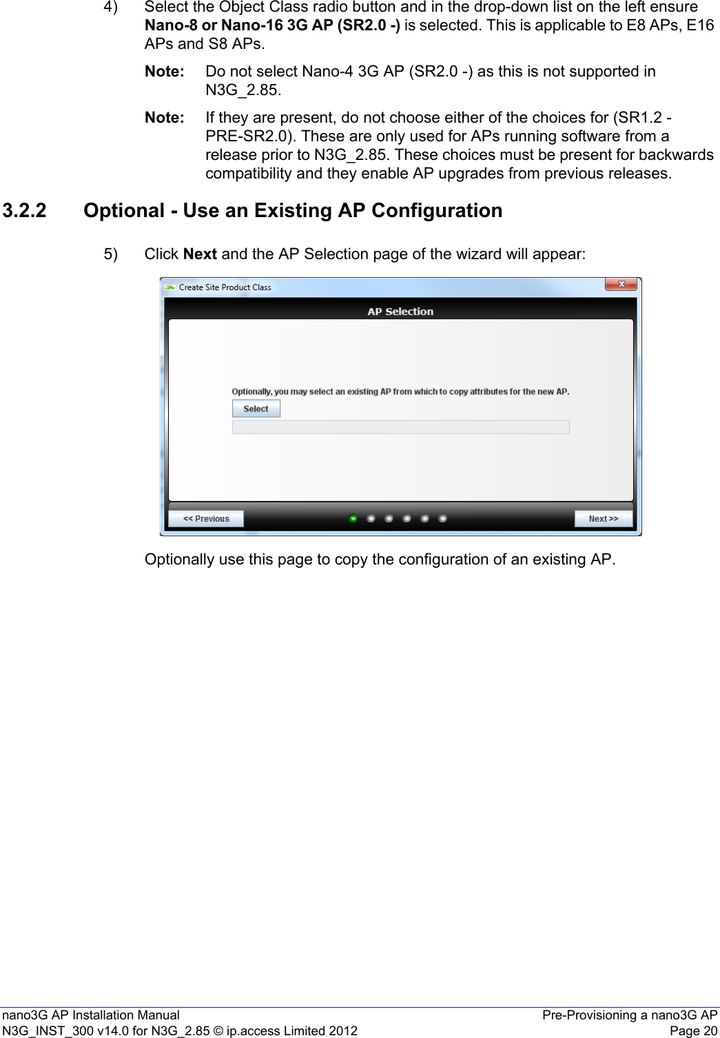
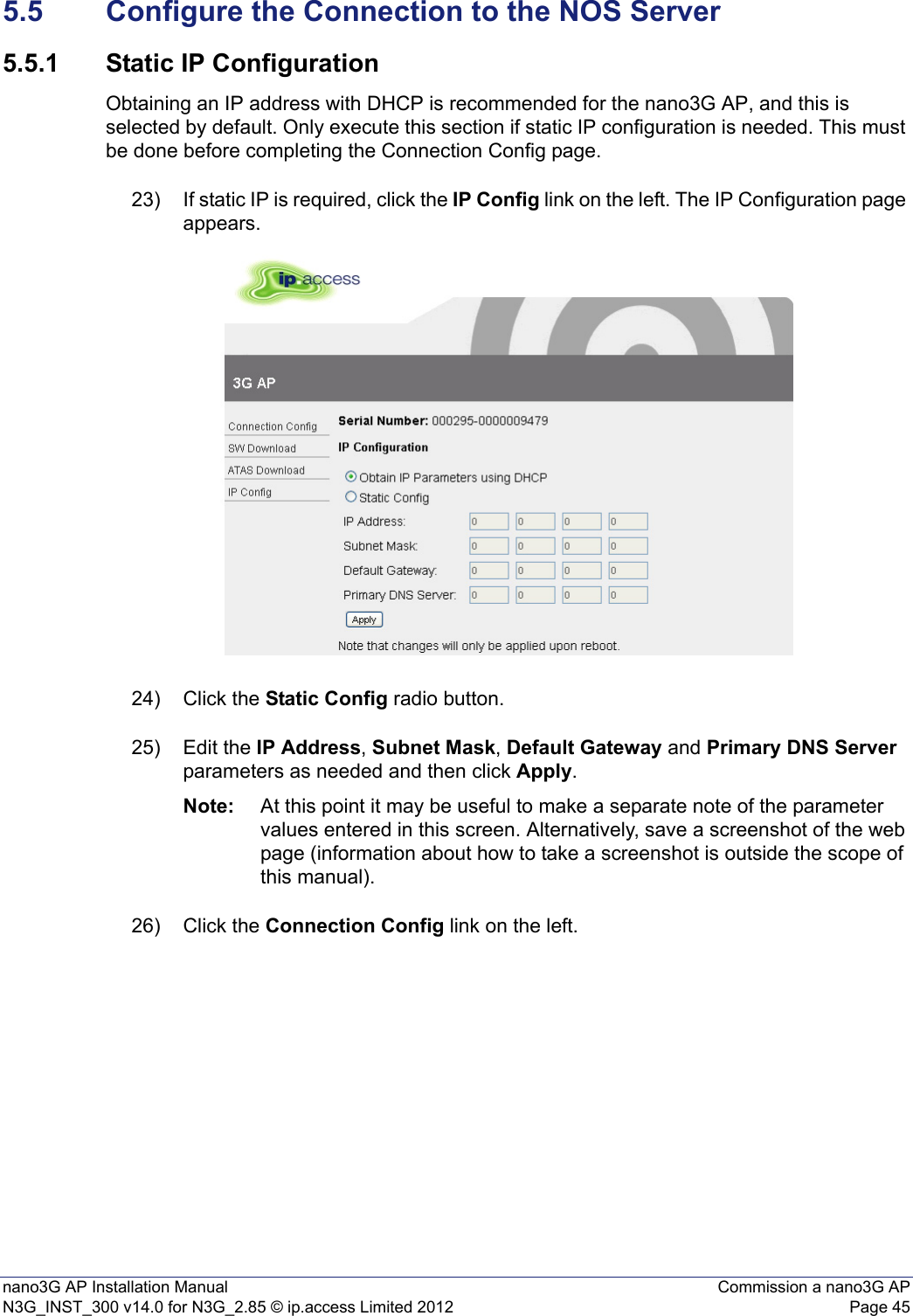
![nano3G AP Installation Manual Installation Overview and RequirementsN3G_INST_300 v14.0 for N3G_2.85 © ip.access Limited 2012 Page 92.2.4 Pre-Prepared Configurations - OptionalThe options described here can be used independently or in any combination.Use an Existing APThe Create Site Wizard, which is used for the initial pre-provisioning of an AP, allows selection of an existing AP as the basis for configuring the new AP. This is a one-time option that is only available in the Create Site Wizard. Configuration FilesAn initial configuration file can be used to rapidly configure the AP via the NOS Create Site Wizard. This is can be an alternative or in addition to using settings from an existing AP or using a template. Additional configuration files can be loaded against the AP object after it has been created by the Create Site Wizard. If they will be used, the location of any configuration files must be known. Configuration files are described in section 4.AP TemplatesAs with configuration files, an initial AP template can be used to rapidly configure the AP via the NOS Create Site Wizard. This can be an alternative to or in addition to using settings from an existing AP or using a configuration file. Additional templates can be applied against the AP object after it has been created by the Create Site Wizard. For information on working with templates, see [OPM_415].](https://usermanual.wiki/ip-access/IPA239B/User-Guide-1776045-Page-15.png)
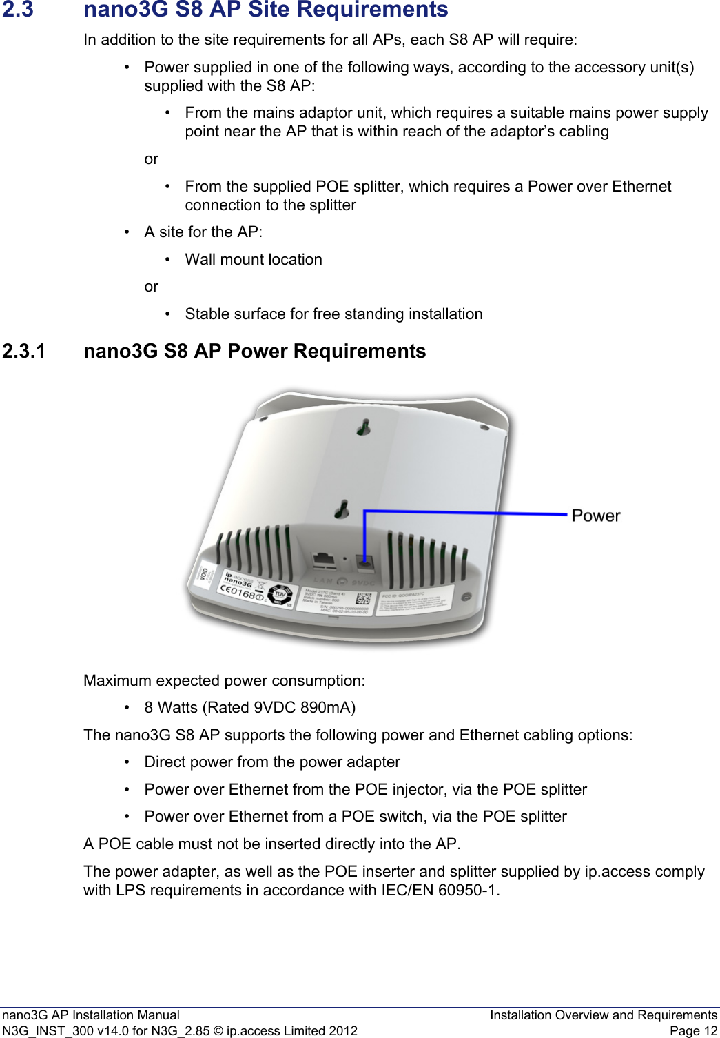
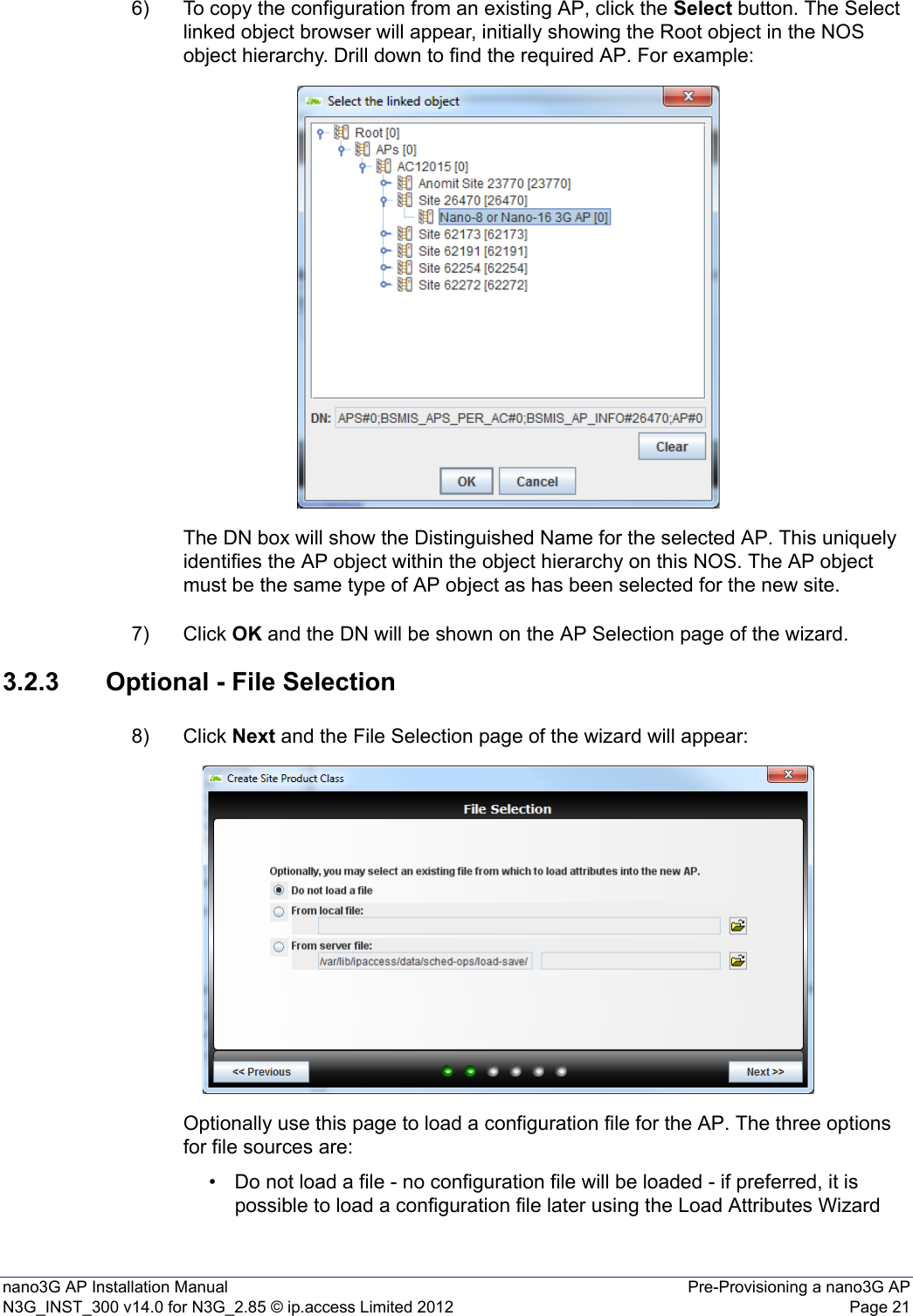
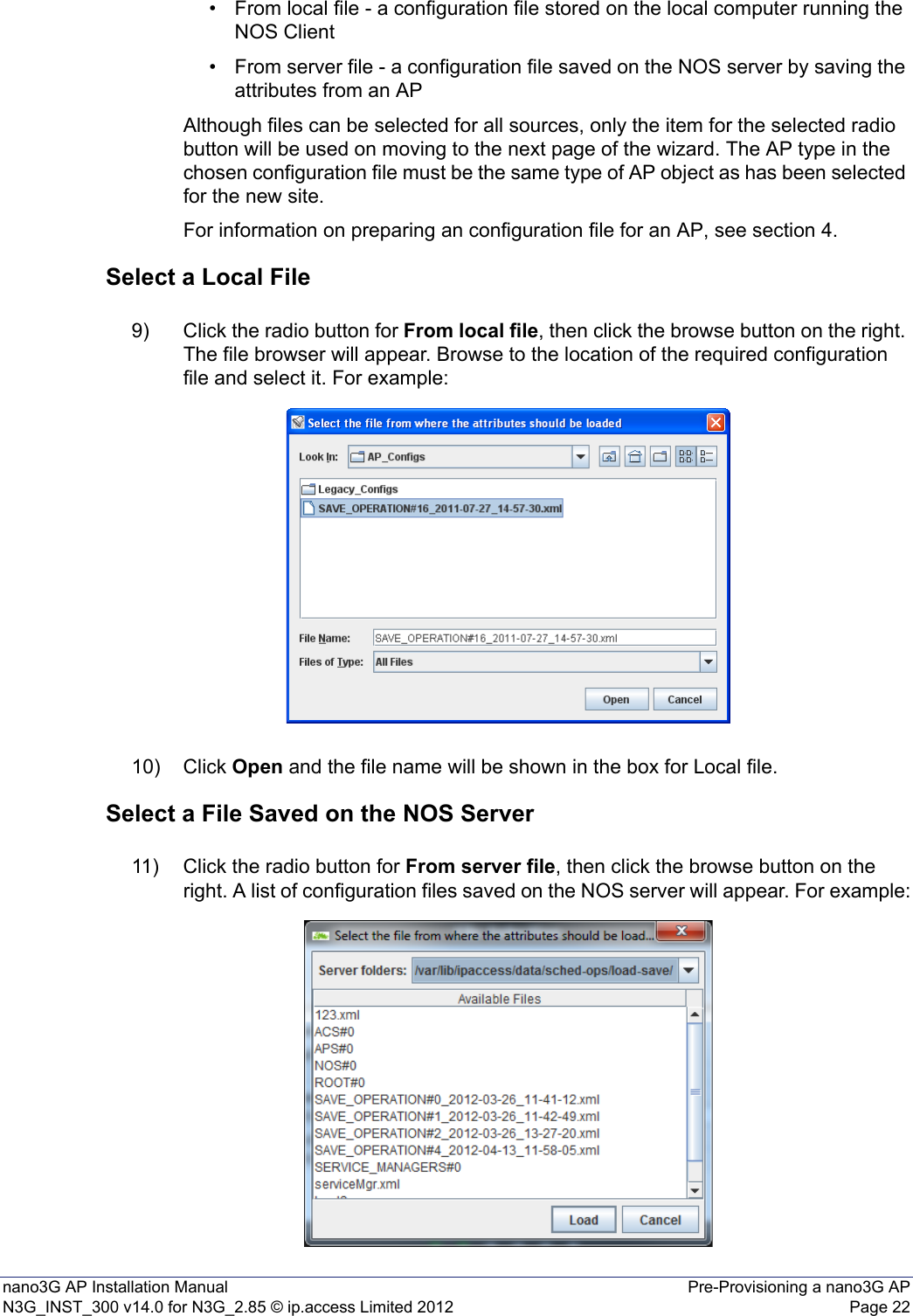
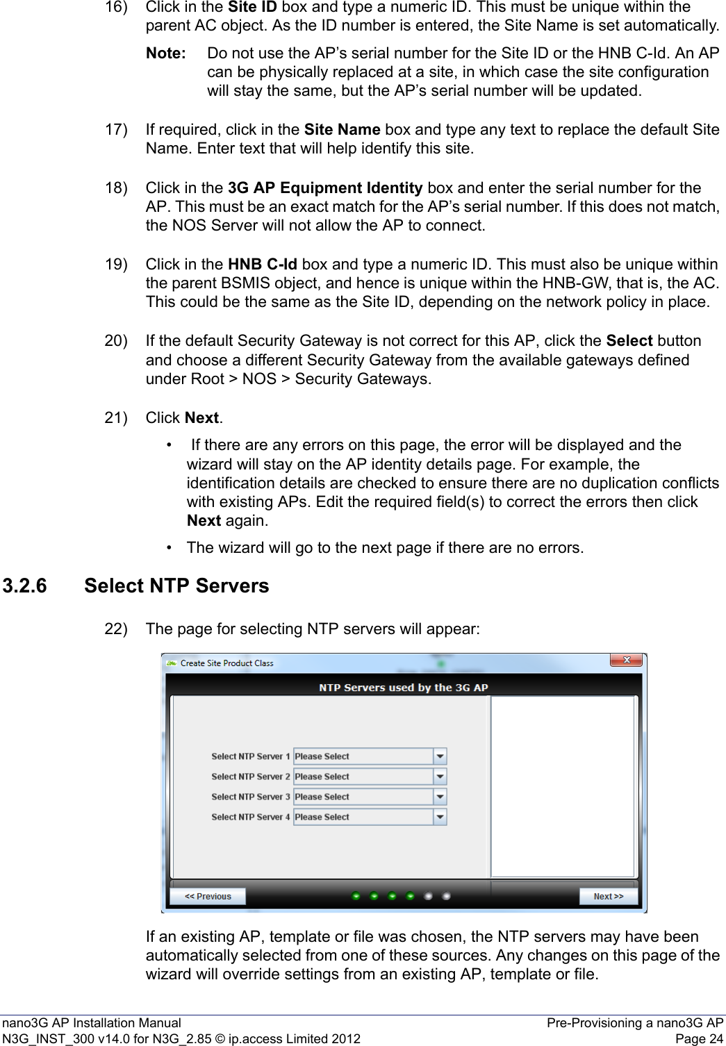
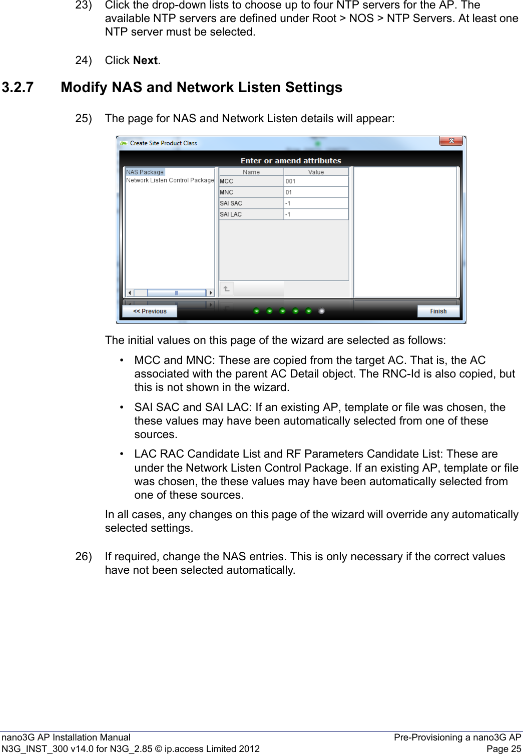
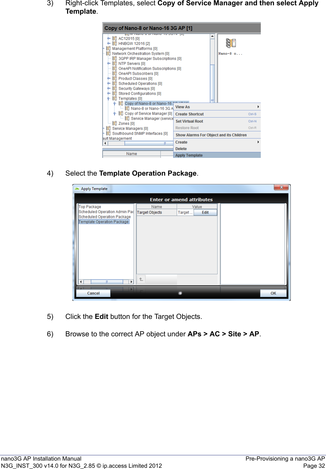
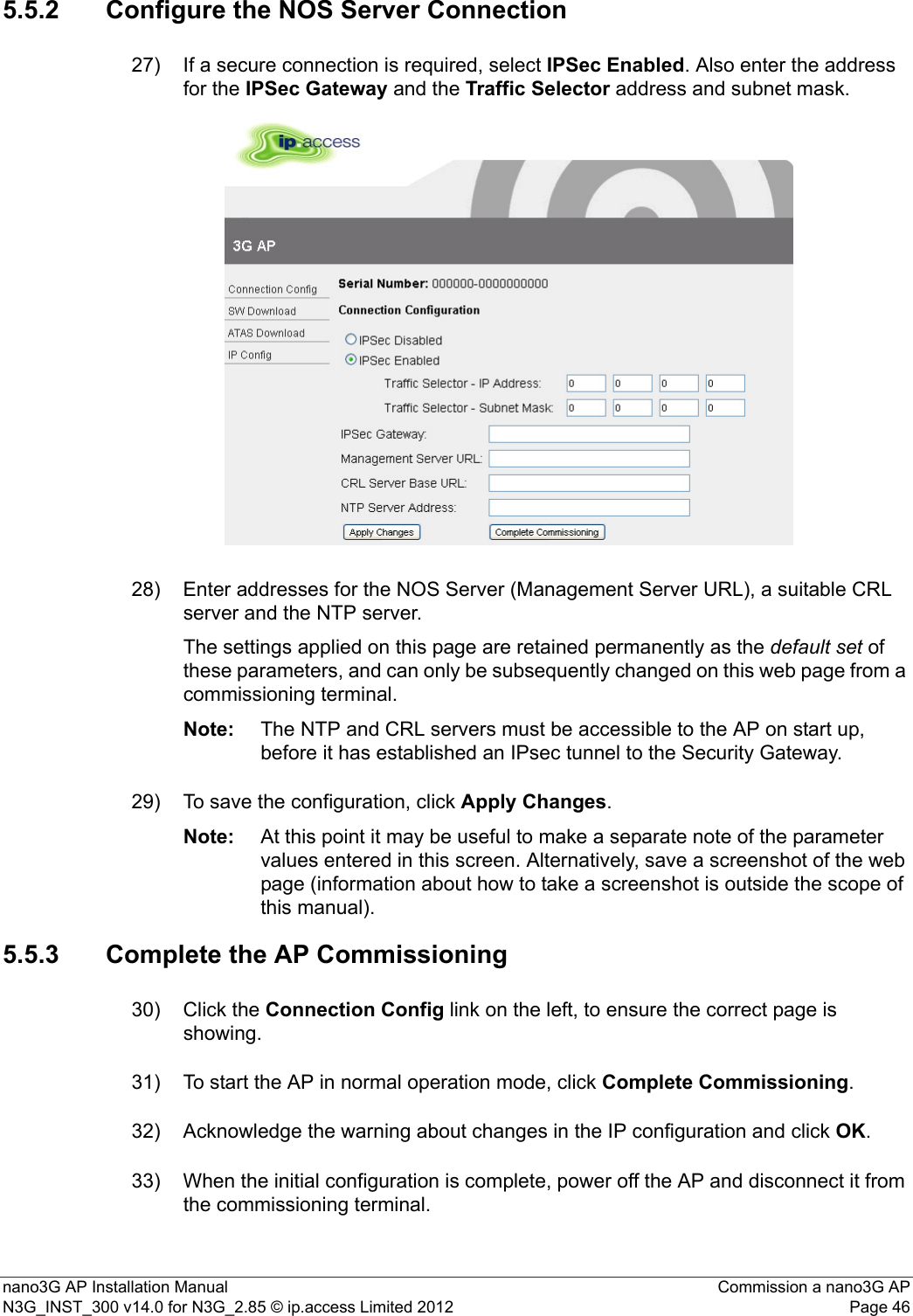
![nano3G AP Installation Manual Pre-Provisioning a nano3G APN3G_INST_300 v14.0 for N3G_2.85 © ip.access Limited 2012 Page 2312) Click the required configuration file in the list, then click Load. The list will close and the file name will be shown in the box for Server file. 3.2.4 Optional - Select an AP Template13) If any templates of the correct object type are available, the Template Selection page will appear:Optionally use this page to load a template for the AP. Typically the template can contain a reference configuration for the AP according to the AP’s intended location and/or usage. For information on working with templates, see [OPM_415].14) To use a template, click the required template in the list, then click Next. If a template is not required for this AP, click Next without selecting anything in the list. 3.2.5 Enter AP Identification Details15) The page for specifying AP identification details will appear:Notice that the 3G AC Name, Management Server Address and Security Gateway are set automatically according to the BSMIS object selected for invoking the wizard. The 3G AC Name and Management Server Address may not be changed.](https://usermanual.wiki/ip-access/IPA239B/User-Guide-1776045-Page-29.png)
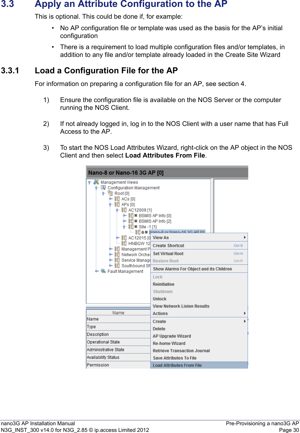
![nano3G AP Installation Manual Pre-Provisioning a nano3G APN3G_INST_300 v14.0 for N3G_2.85 © ip.access Limited 2012 Page 314) The Load Attributes From File Wizard shows the chosen AP object:5) Choose From server file or From local file, according to the location of the edited configuration file.6) Click the Browse button then use the file browser to select the edited configuration file.7) Click the Load or Open, according to which file browser is in use, and the file name is shown in the Load Attributes wizard. Click Next.8) By default the operation is scheduled for Now, so click Finish to load and apply the configuration settings.9) Repeat as needed, if there are multiple configuration files.3.3.2 Apply an AP Template to the APFor information on working with templates, see [OPM_415].1) If not already logged in, log in to the NOS Client with a user name that has Full Access to the AP.2) Find the required AP template under NOS > Templates.The object type must match. That is, use an apNano8_020 template for E8 APs, E16 APs and S8 APs. Choosing a template with a different object type will have no effect on the target AP.](https://usermanual.wiki/ip-access/IPA239B/User-Guide-1776045-Page-37.png)
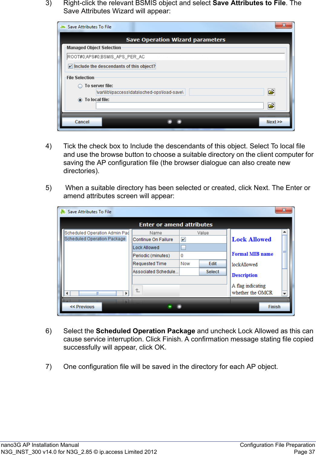
![nano3G AP Installation Manual Configuration File PreparationN3G_INST_300 v14.0 for N3G_2.85 © ip.access Limited 2012 Page 344 Configuration File PreparationThe attribute values for configuring a nano3G AP can be stored in an XML file, and then loaded via the NOS Client to provision the AP. This configuration file of attributes can be loaded when creating the site for the AP or at any time after that once the AP object exists. This section describes how to prepare one or more configuration files of attributes for provisioning nano3G APs. This can be done in combination with the Create Site Wizard and configuration adjustments from the NOS Client, according to whichever method is best suited for given configuration tasks. 4.1 Overview of Configuration FilesA configuration file is an XML file containing an AP object that has named attributes and the value for each attribute. Each attribute definition is of the form:<cd:attribute registeredAs="NUM" name="NAME">VALUE</cd:attribute>Where:• NUM is the Registered As number, as specified in the MIB for this attribute• NAME is the attribute name, as specified in the MIB for this attribute• VALUE is the attribute value, which must conform to the attribute’s definition in the MIBThe attribute types and values they may take are formally described in [REF_110]. Note: In the configuration file, the values of compound attributes, such as RAB types, are defined within brackets (). In the NOS Client, the compound types are the complex attributes that have multiple levels within the Navigation and Properties panes. To work with compound attributes in a configuration file, it is recommended to use the structure in the OMC-R Client as a guide to editing the compound attribute.Note: In [REF_110], there is a distinction between expert and non-expert attributes. As a general rule, it is recommended to leave expert attributes at their default values. The configuration file must contain the correct distinguished name (DN) for the target AP. The NOS Client will not load a file if the DN does not match. In the configuration file, the DN is the localDn field near the beginning of the file. To change which AP this file applies to, edit the last part of the DN which defines the connection instance (the site) and AP instance.Although a configuration file can be created from scratch, it is more practical to save a file from within the NOS Client from an object of the same type and then edit the file for the target object. The resulting configuration file can then be imported against the target object, which in this case will be an AP.Configuration files must be imported one at a time, but there is no restriction on the number of configuration files that can be imported to configure any given object. This means it is possible to create a generic configuration file, which contains attribute values common to all APs of the same type. Typically, this can be started by exporting the configuration from an AP that has already been fully configured, and then edited to remove non-generic attributes. Once the generic file has been created, it must be saved for each AP, with the correct DN.](https://usermanual.wiki/ip-access/IPA239B/User-Guide-1776045-Page-40.png)
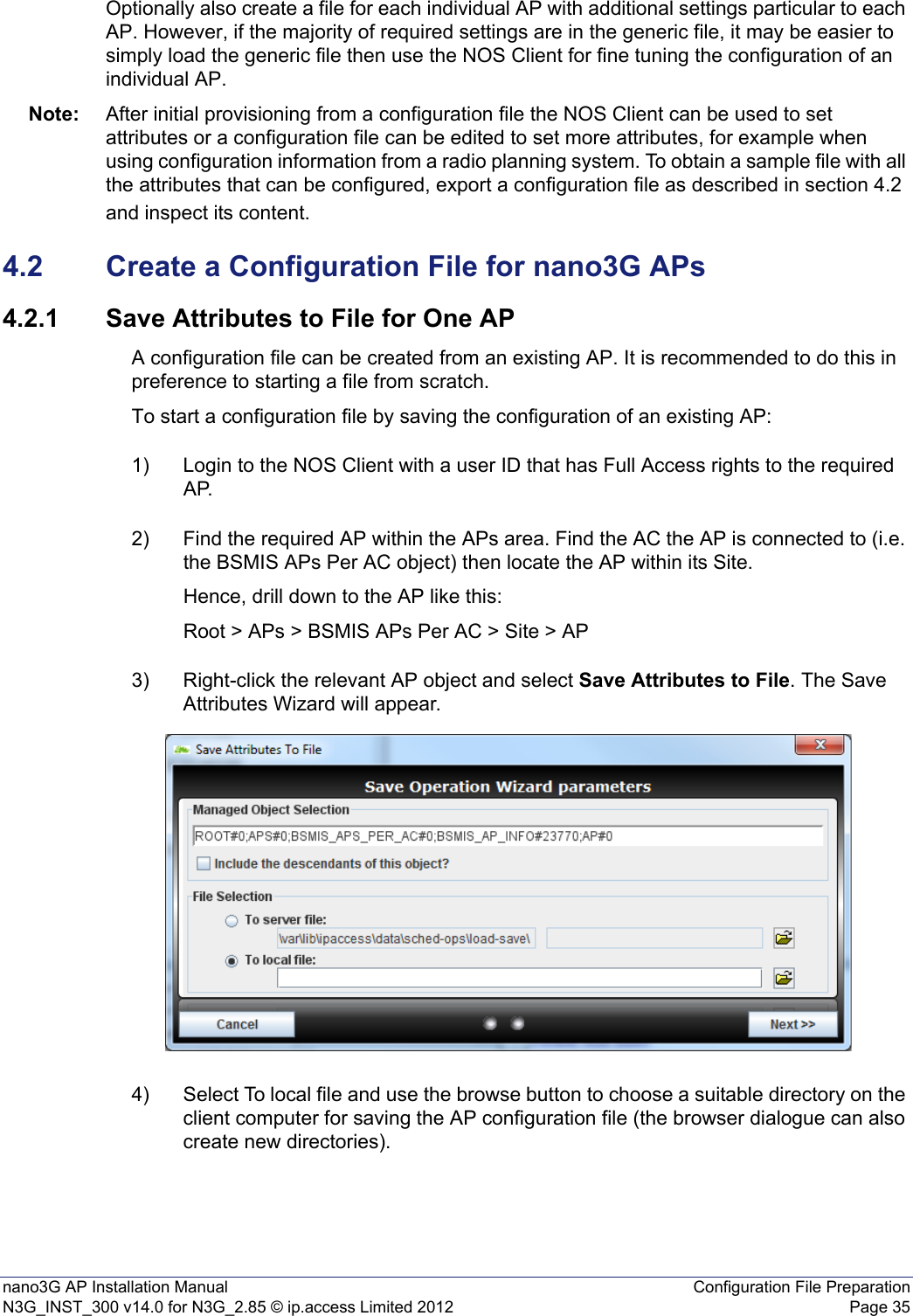
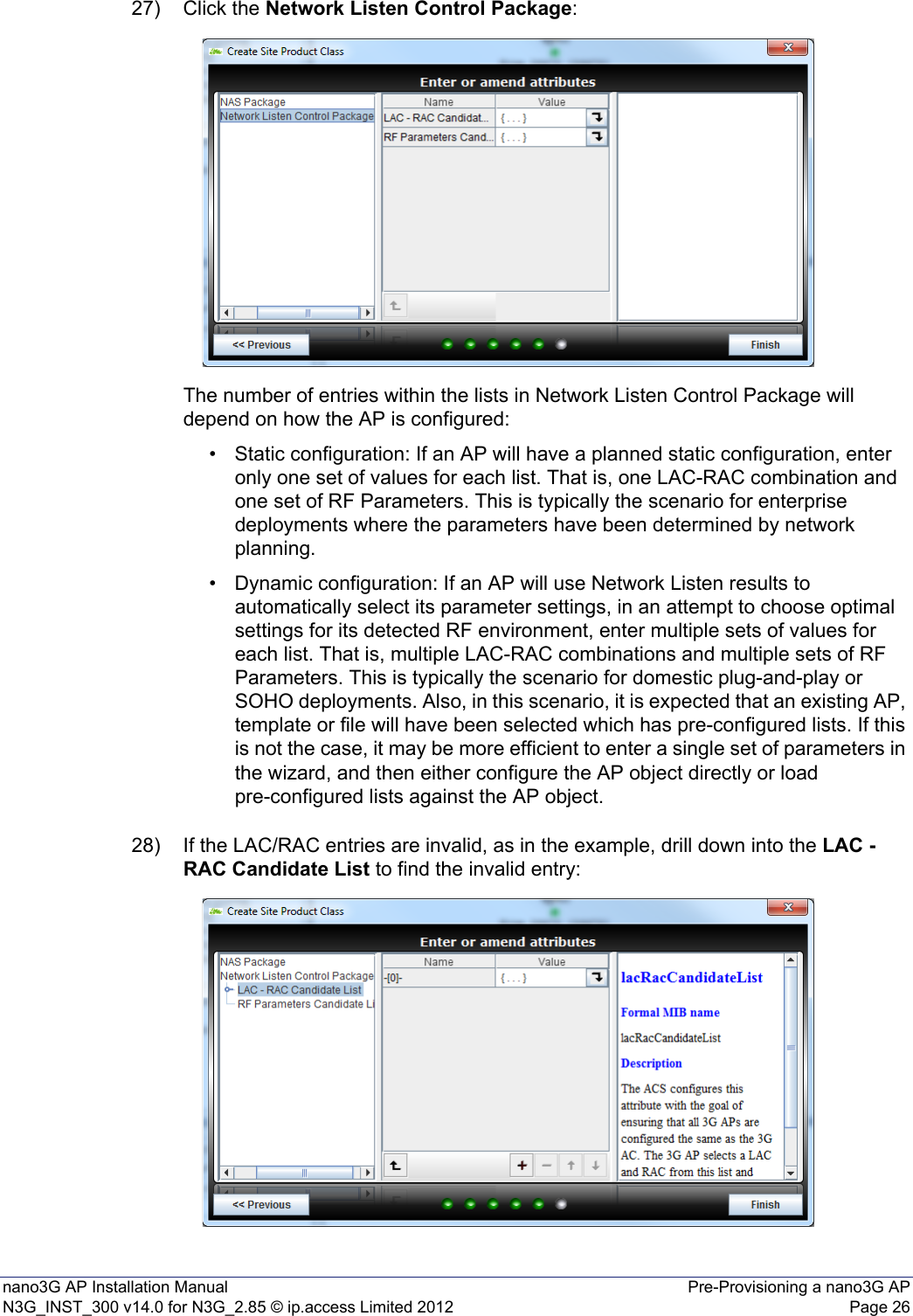
![nano3G AP Installation Manual Configuration File PreparationN3G_INST_300 v14.0 for N3G_2.85 © ip.access Limited 2012 Page 365) When a suitable directory has been selected or created, click Next. The Enter or amend attributes screen will appear:6) Select the Scheduled Operation Package and uncheck Lock Allowed as this can cause service interruption. Click Finish. A confirmation message stating file copied successfully will appear, click OK.7) One configuration file will be saved in the directory for each AP object.4.2.2 Save Attributes to File for Multiple APsUse this function to make a backup of the configuration attributes for all APs within the AC BSMIS of one AC. One configuration file will be saved for all AP objects below the selected AC BSMIS object. The file name is generated automatically with the following format:.Bulk backup is local only (i.e. on the Client computer). It is not possible to bulk backup the AP configurations on the SDP Server.The whole directory can be restored.1) Login to the NOS Client with a user ID that has Full Access rights to the required AP.Note: For full information on using the NOS Client, see [OPM_415].2) Find the required AP within the APs area. Find the AC the AP is connected to (i.e. the BSMIS APs Per AC object) then locate the APwithin its Site. Hence, drill down to the AP like this:Root > APs > BSMIS APs Per AC](https://usermanual.wiki/ip-access/IPA239B/User-Guide-1776045-Page-42.png)

![nano3G AP Installation Manual Finalize InstallationN3G_INST_300 v14.0 for N3G_2.85 © ip.access Limited 2012 Page 647 Finalize InstallationAll the activities in this section are managed from the NOS Client.7.1 Check and Upgrade the nano3G AP Software ImageThis is a useful check to ensure that the AP has the required software version, even if the AP software was recently updated during commissioning. 7.1.1 Check the Current Software Image Version1) Login to the NOS Client with a user name (and password) that has Full Access rights for changing the AP's configuration.2) Find the required AP within the AP area. Find the AC the AP is connected to (i.e. the BSMIS APs Per AC object) then locate the AP within its Site. Hence, drill down to the AP like this:Root > APs > BSMIS APs Per AC > Site > APNote: For full information on using the NOS Client, see [OPM_415].3) Verify that the Site has a green tick, to show that the AP is connected to the NOS Server. The AP object, below the Site, may be currently locked. The AP will remain locked if it is not ready to provide service. 4) In the Navigation pane, browse to the AP Admin Package.5) Check the values of the Active SW Version and Standby SW Version attributes.6) If the AP does not have the latest software image, download it to the AP from the NOS Server according to the instructions in section 7.1.2.](https://usermanual.wiki/ip-access/IPA239B/User-Guide-1776045-Page-70.png)
![nano3G AP Installation Manual Finalize InstallationN3G_INST_300 v14.0 for N3G_2.85 © ip.access Limited 2012 Page 657.1.2 Download the Latest Software Image from the NOS Server to the APFor instructions about how the software images (SDP files) are uploaded to the NOS Server, see [OPM_440].1) Select the AP in the NOS Client.2) Right-click the AP, select Actions and then Perform Software Download. The Perform Software Download Actions dialogue box will appear. 3) Change the SW Download Operations to Download, Swap and Reboot.4) Click in the SW Image Download URL box and enter the URL of the required SDP file using the following URL pattern:http://<server>/download/sw/<filename>.sdpWhere <server> is the IP address or host name of the required NOS Server, and <filename>.sdp is the required software download package file.5) Press <TAB> or <Enter> to set the URL.6) Click Finish and the download will take place. On the AP, download progress is indicated by the flashing network LED. When the download is complete, the AP will reboot under the new software. This may take several minutes. 7) Wait for the AP to be shown as connected to the NOS.8) Select the 3G AP Admin Package for the AP object and verify that the Filesys version reported by the Active Software Version matches the SDP file that was downloaded.](https://usermanual.wiki/ip-access/IPA239B/User-Guide-1776045-Page-71.png)
![nano3G AP Installation Manual Finalize InstallationN3G_INST_300 v14.0 for N3G_2.85 © ip.access Limited 2012 Page 667.2 Finalize Configuration7.2.1 Final Attribute Changes and Checks1) Login to the NOS Client with a user name that has Full Access to the required AP.2) Make any AP-specific configuration changes that have not already been applied by the Create Site Wizard or loading configuration files. In particular, ensure the static neighbour lists are correctly configured. See [OPM_300] for information on neighbour list configuration. 3) Spot check any or all of the following packages to verify the attributes are set to the correct values:• Cell Package•NAS Package• Location Package7.2.2 Automatic Configuration BackupThe configuration of an AP is automatically backed up on the NOS server each time configuration changes are applied from the NOS Client. The configuration files are named according to the AP serial numbers. A file is overwritten automatically by subsequent configuration changes. The files are saved in: /var/lib/ipaccess/data/auto-ap-backup7.2.3 Network Listen and Frequency Correction1) If not already logged in, login to the NOS Client with a user name that has Full Access to the required AP.2) Select the AP object within the managing AP Management Service, AC Detail and Site. Select its 3GAP Time package, then wait a few seconds for the Up Time attribute to update. Verify that this is at least 1200, which is 20mins, before continuing. This ensures the frequency crystal has had some time to warm up and achieve a degree of thermal stability prior to checking if it needs any frequency correction. If necessary, wait until the Up Time passes 1200 seconds.3) An AP must be locked to execute a Network Listen scan. Right-click the AP object and select Lock, then wait until a small padlock symbol is shown against the AP icon. 4) To execute a Network Listen scan, right-click the AP object, select Actions and then select Start Sequential NWL Scan. 5) When the scan is complete, view the results and verify there is some radio activity detected, and ideally some neighbour cells. This will confirm the radio is working.](https://usermanual.wiki/ip-access/IPA239B/User-Guide-1776045-Page-72.png)
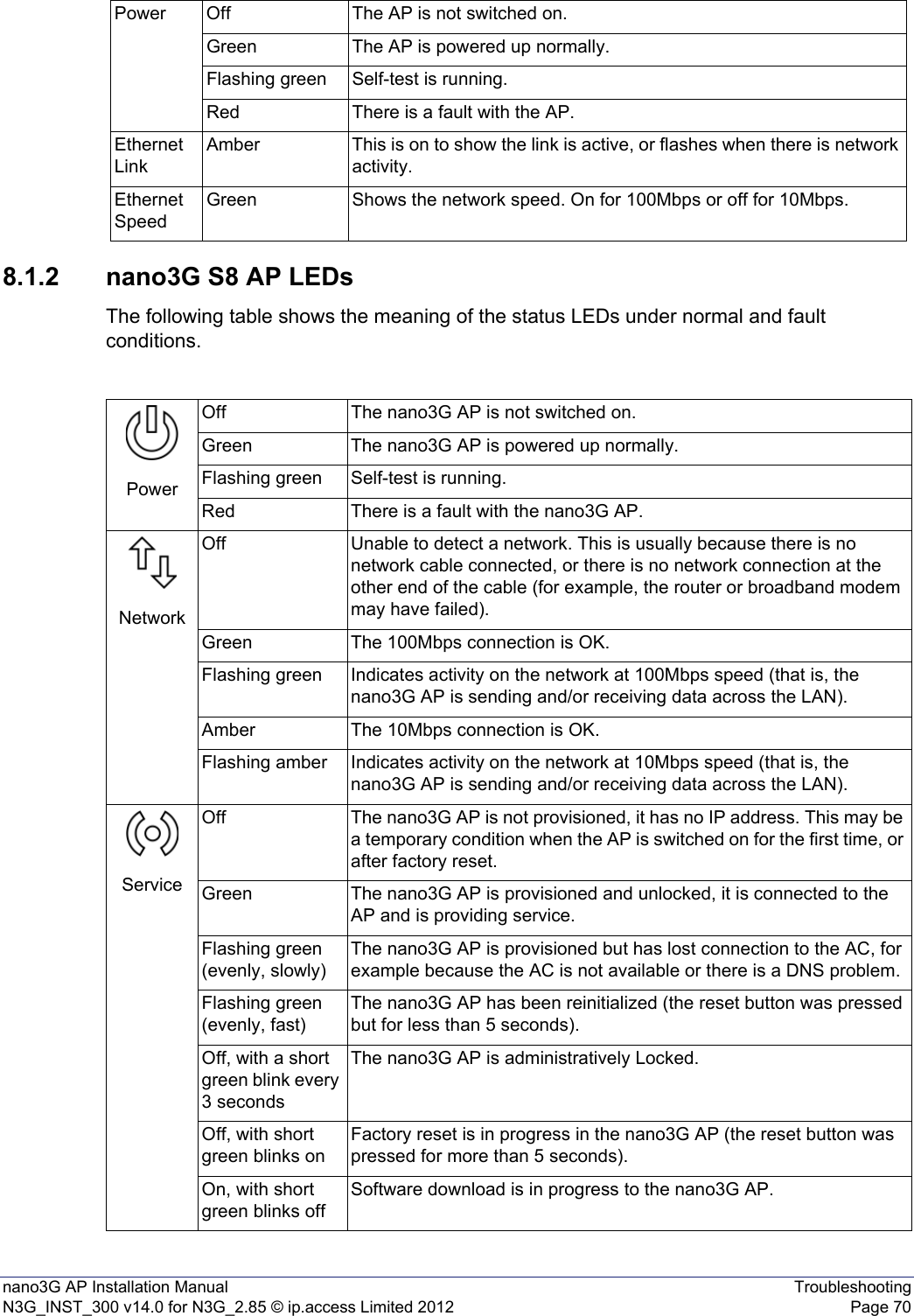
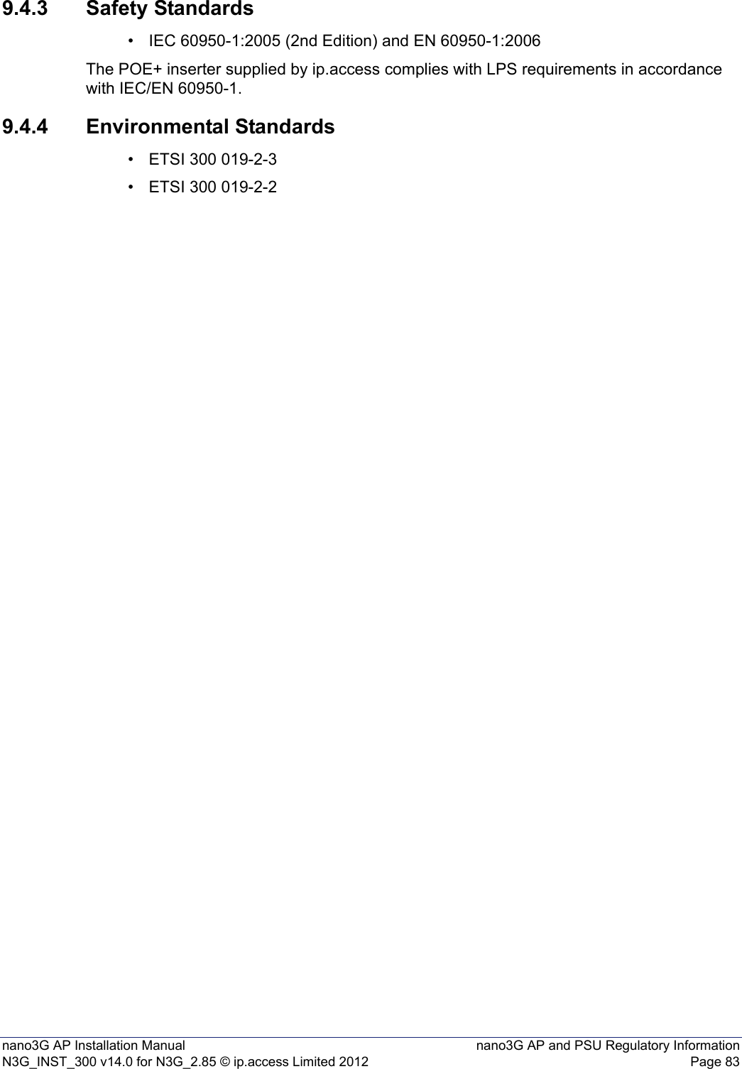
![nano3G AP Installation Manual TroubleshootingN3G_INST_300 v14.0 for N3G_2.85 © ip.access Limited 2012 Page 698 TroubleshootingThis section covers the following topics that may be useful for troubleshooting APs during installation and commissioning:•8.1 LED Status Indicators•8.2 nano3G E8 AP or E16 AP Does Not Start Up•8.3 Factory Reset•8.4 Options for a Low Bandwidth ConnectionFor more information on AP troubleshooting, see [TRB_300].8.1 LED Status Indicators8.1.1 nano3G E8 AP and nano3G E16 AP LEDsThe following table shows the meaning of the status indicators under normal and fault conditions.3G Off The AP is not provisioned, it has no IP address. This may be a temporary condition when the AP is switched on for the first time, or after factory reset.Green The AP is provisioned and unlocked, it is connected to the AC and is providing service.Flashing green(evenly, slowly)The AP is provisioned but has lost connection to the AC, for example because the AC is not available or there is a DNS problem.The AP is locked.Flashing green(evenly, fast)The AP has been reinitialized (the reset button was pressed but for less than 5 seconds).Off, with short green blinks onFactory reset is in progress in the AP (the reset button was pressed for more than 5 seconds).On, with short green blinks offSoftware download is in progress to the AP.](https://usermanual.wiki/ip-access/IPA239B/User-Guide-1776045-Page-75.png)