ip access IPA435R Access point User Manual NANO INST 43315 nanoLTE S60 AP Hardware Installation v200 0 5
ip.access ltd Access point NANO INST 43315 nanoLTE S60 AP Hardware Installation v200 0 5
Contents
- 1. NANO_INST_43315_nanoLTE_S60_AP_Hardware_Installation_v200_0.5
- 2. S60 Datasheet Apr 2017 v1.0
NANO_INST_43315_nanoLTE_S60_AP_Hardware_Installation_v200_0.5

![nanoLTE S60 AP Hardware Installation IntroductionNANO_INST_43315 v200_0.5 for N4G_2.0 © ip.access Limited 2017 Page 11 IntroductionThe ip.access nanoLTE S60 AP is an indoor Access Point for SOHO and enterprise small cell applications.This manual provides all the necessary information required for hardware installation of a nanoLTE S60 AP.1.1 OverviewThis manual is organised as follows:• This introduction• An overview of nanoLTE S60 AP installation, including site requirements• nanoLTE S60 AP hardware installation• Troubleshooting• Regulatory warnings and safety information1.2 Warnings and Regulatory InformationFor all warnings and regulatory information, see section 5.1.3 Related Information1.4 Licenses and Copyright NoticesPortions of the AP are constructed from third-party software and open source code and ip.access Ltd gratefully acknowledges the contributions that these libraries, technologies and components have made to the product. Each of these is supplied under the terms of a license agreement and these are either reproduced or referenced in [REF_43005], in line with the stipulations of their authors.1.5 TerminologyCommon System terminology is defined in [REF_11105].For additional terminology, see [21.905].[GST_41050] nanoLTE System Planning (NANO_GST_41050)[INST_43370] nanoLTE AP Pre-Provisioning and Configuration (NANO_INST_43370)[OPM_43005] nanoLTE AP Operations (NANO_OPM_43005)[REF_11105] System Glossary (NANO_REF_11105)[REF_43005] nanoLTE AP Open Source Software (NANO_REF_43005)[TRB_43005] nanoLTE AP Troubleshooting (NANO_TRB_43005)[21.905] Vocabulary for 3GPP Specifications (3GPP TR 21.905)](https://usermanual.wiki/ip-access/IPA435R.NANO-INST-43315-nanoLTE-S60-AP-Hardware-Installation-v200-0-5/User-Guide-3625945-Page-6.png)
![nanoLTE S60 AP Hardware Installation Installation Overview and RequirementsNANO_INST_43315 v200_0.5 for N4G_2.0 © ip.access Limited 2017 Page 22 Installation Overview and Requirements2.1 Installation TasksThe tasks that must be completed to install a nanoLTE S60 AP and make it ready to provide service are: • Pre-Provisioning• Site installation These tasks can be completed in any order. In most cases, however, the most practical approach is to pre-provision an S60 AP before site installation. 2.1.1 Pre-ProvisioningFor information about nanoLTE AP pre-provisioning, see the nanoLTE AP Configuration manual [INST_43370]. This manual has no further information on AP configuration.2.1.2 Site InstallationPhysical installation of a nanoLTE S60 AP at its operating site, including providing the AP with power and a suitable network connection. The network connection provides a backhaul path to the NOS Server and EPC or S1 Gateway.The network connection must also provide Internet access so that the S60 AP can the services it needs at boot time, including NTP, the Redirector and the public CRL mirror.If a nanoLTE S60 AP has been enabled for service prior to the site visit, the installation engineer can make test calls immediately. 2.2 Mounting OptionsThe mounting options for the nanoLTE S60 AP are:• Wall mounted, by using the wall mounting holes on the back of the unit (suitable pan-head screws must be sourced separately) • Free standing, on the supplied stand, which must be placed on a stable flat surfaceThe hardware installation instructions in section 3 cover both options.](https://usermanual.wiki/ip-access/IPA435R.NANO-INST-43315-nanoLTE-S60-AP-Hardware-Installation-v200-0-5/User-Guide-3625945-Page-7.png)
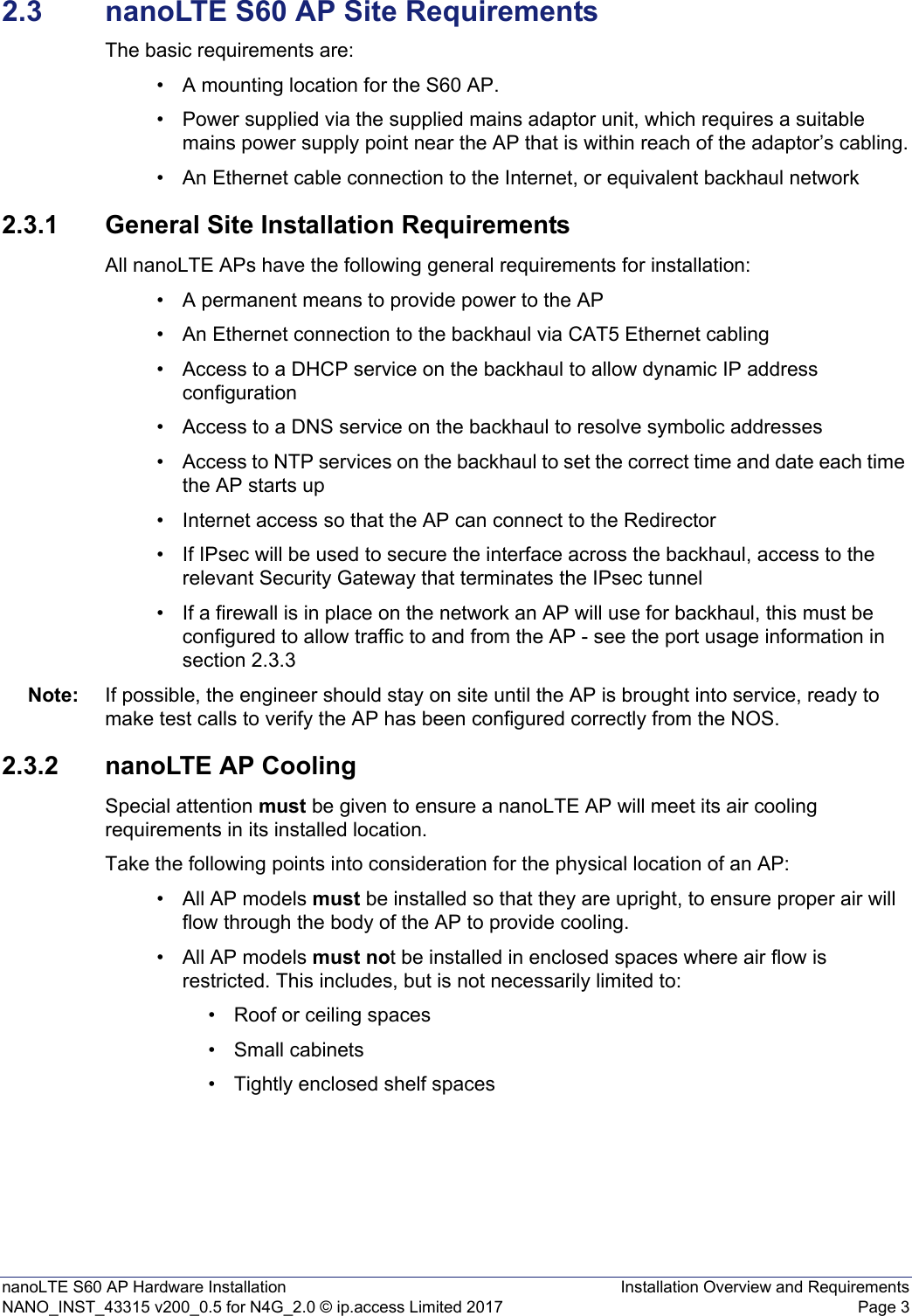
![nanoLTE S60 AP Hardware Installation TroubleshootingNANO_INST_43315 v200_0.5 for N4G_2.0 © ip.access Limited 2017 Page 114 TroubleshootingThis section covers the following topics that may be useful for troubleshooting a nanoLTE S60 AP during installation:•4.1 nanoLTE S60 AP Does Not Power Up•4.2 nanoLTE S60 AP LEDs•4.3 Factory ResetFor more information on AP troubleshooting, see [TRB_43005].4.1 nanoLTE S60 AP Does Not Power UpCheck the following:• Verify the correct power supply is in use and that mains power is available.• Ensure that PoE or PoE+ is not being used to attempt to power the AP. The presence of power on the Ethernet connection has no effect on the S60 AP.4.2 nanoLTE S60 AP LEDsThe following table shows the meaning of the status indicators under normal and fault conditions.LED Colour DescriptionPowerOff The nanoLTE AP is not switched on.Green The nanoLTE AP is powered up normally.Red The LED should only be Red for a short time when the nanoLTE AP is starting up. If the LED stays Red, this means there is a fault with the AP.If the LED turns Red after previously turning Green, this means that there is a hardware power fault with the nanoLTE AP.](https://usermanual.wiki/ip-access/IPA435R.NANO-INST-43315-nanoLTE-S60-AP-Hardware-Installation-v200-0-5/User-Guide-3625945-Page-16.png)
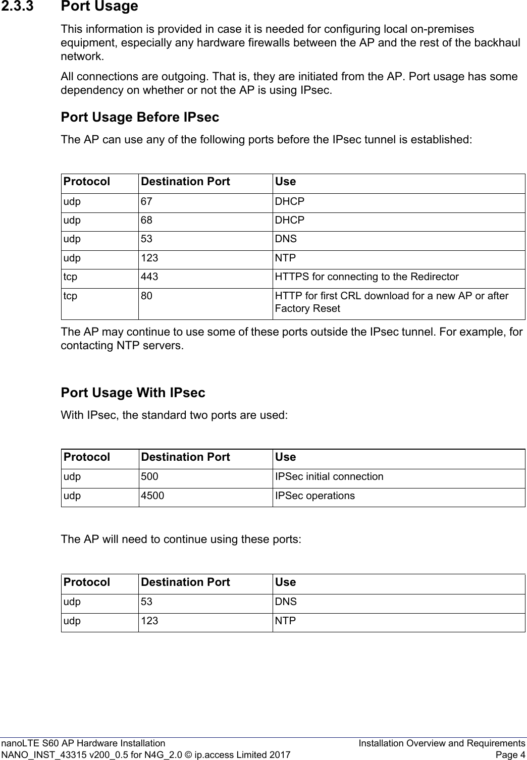
![nanoLTE S60 AP Hardware Installation TroubleshootingNANO_INST_43315 v200_0.5 for N4G_2.0 © ip.access Limited 2017 Page 15To resolve any incorrect provisioned values, correct them in the NOS then perform a factory reset. The AP will reconnect to the NOS using the default factory configuration and then obtain the updated configuration. 4.3.1 S60 Factory Reset1) Use a thin rod to press and hold the reset button, which is accessed through a small hole under the Ethernet port. 2) Keep the reset button pressed until the Service LED changes from blinking fast (50ms on, 50ms off) to blinking slowly (50ms on, 200ms off). The 4G Service LED blinks fast (50ms on, 50ms off) until the factory reset commences, then it blinks slowly (50ms on, 200ms off). When the factory restore process is complete, the LED extinguishes and the AP automatically reboots. The AP will then attempt to re-contact the Redirector via the Internet, in case there is an updated OLM Package available (for example, if the DOCP for the AP has been modified and/or there are new certificates for the AP). The AP will then attempt to reconnect to the specified IPsec Security Gateway and NOS. If the AP is unable to reconnect to the Redirector, it will use the existing DOCP parameters. 3) See the nanoLTE AP Troubleshooting manual [TRB_43005] for the full AP restart sequence following a factory reset.](https://usermanual.wiki/ip-access/IPA435R.NANO-INST-43315-nanoLTE-S60-AP-Hardware-Installation-v200-0-5/User-Guide-3625945-Page-20.png)