ip access KU02ZZR GSM 850 picocellular basestation User Manual CENG0336 nanoBTS Installation and Test Manual
ip.access ltd GSM 850 picocellular basestation CENG0336 nanoBTS Installation and Test Manual
UserManual.wiki
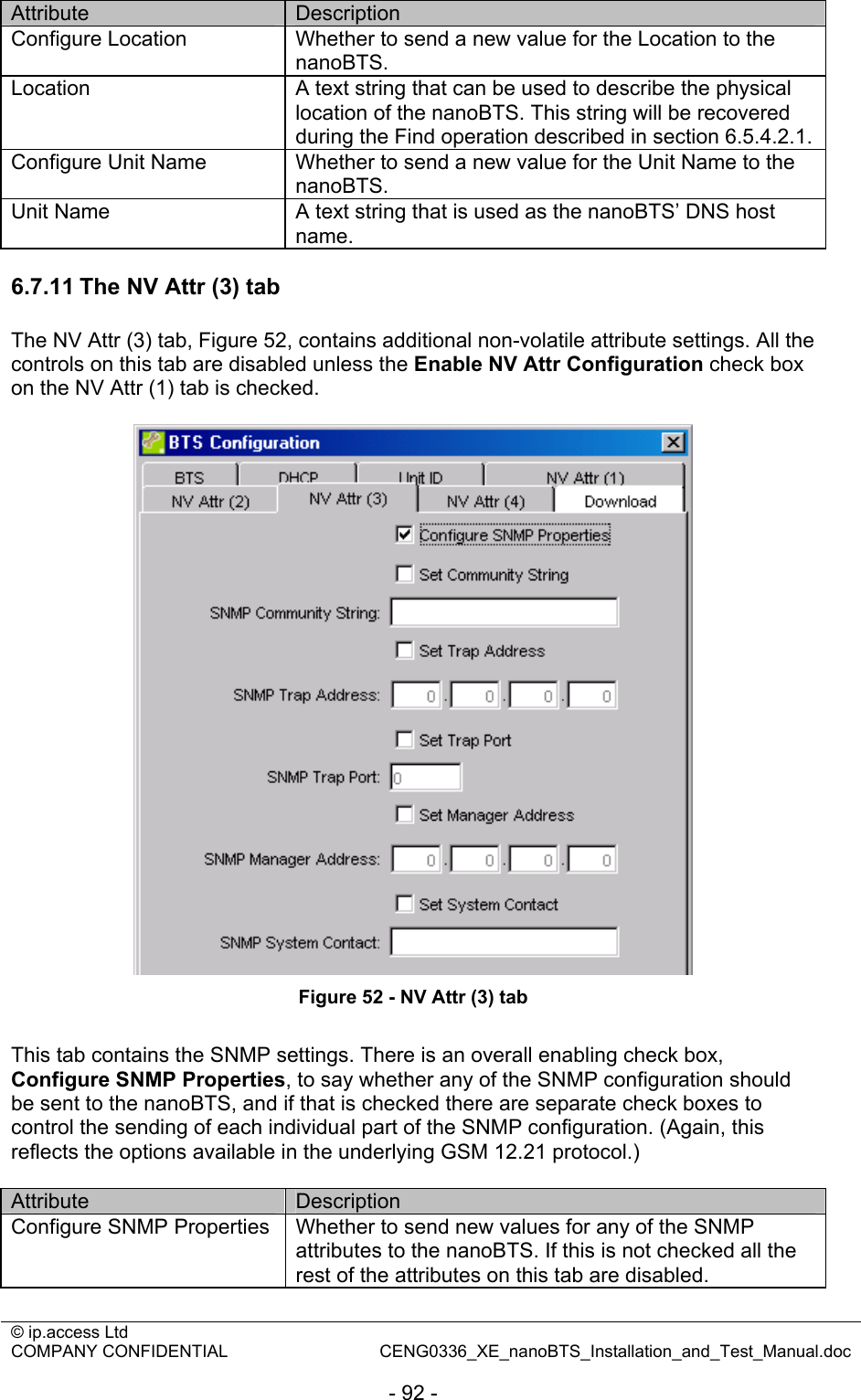
>
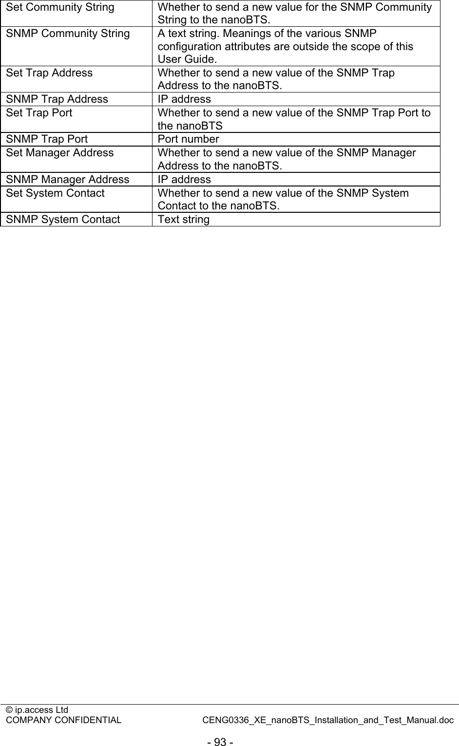
ip access
>
KU02ZZR User Manual
Installation and test manual
Navigation menu
Upload a User Manual
Namespaces
Wiki Guide
HTML
PDF
Info
Views
User Manual
Discussion / Help
Navigation


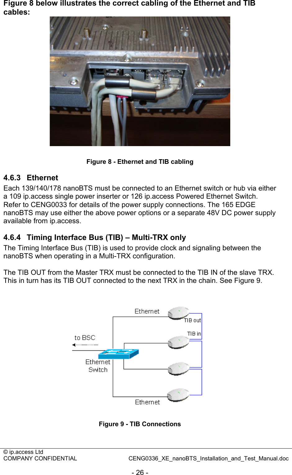
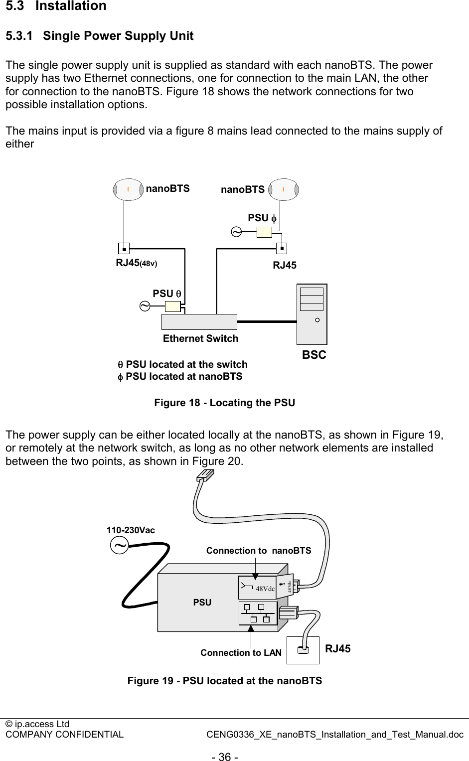
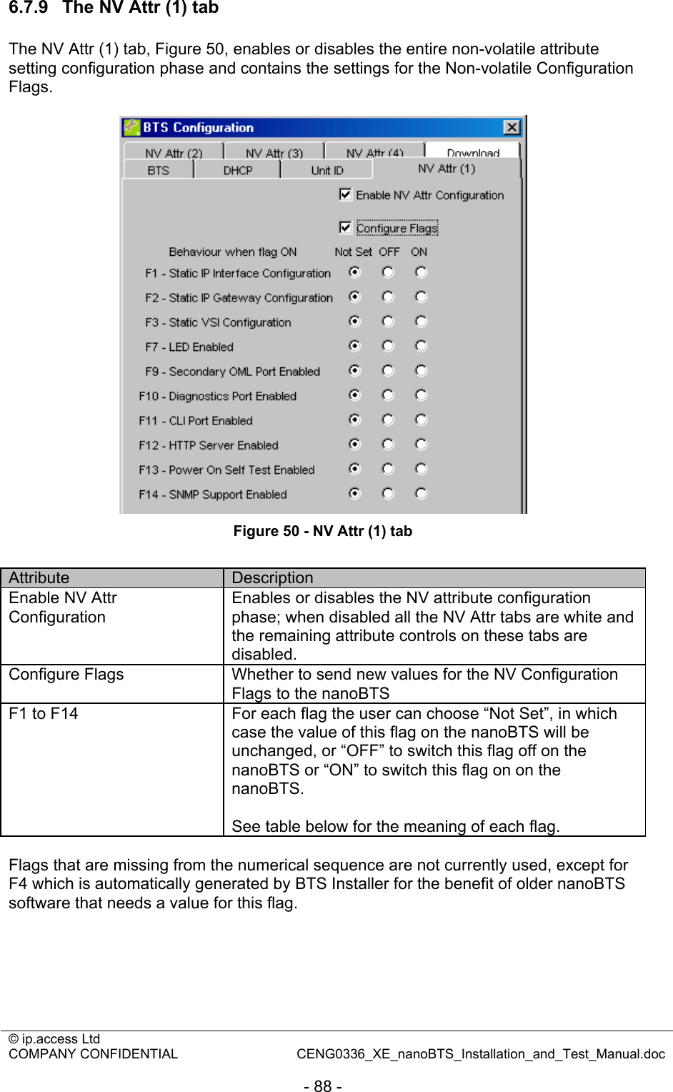
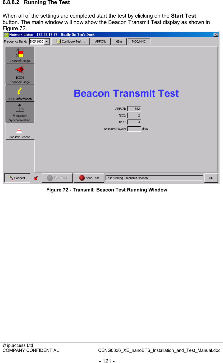
![© ip.access Ltd COMPANY CONFIDENTIAL CENG0336_XE_nanoBTS_Installation_and_Test_Manual.doc - 22 - 4 BTS Hardware Installation (CENG0210) 4.1 Introduction 4.1.1 Purpose and Scope This documents the procedure used to install the nanoBTS hardware and physical connections together with applying the base software configuration. 4.2 Warnings Please refer to the appropriate section of CENG0133 [1]. 4.3 Regulatory Information For all regulatory information please see CENG0133 [1]. 4.4 Unpacking Unpack nanoBTS and check to see that the unit has not been damaged in transit. Any damaged units should be returned to your supplier. Figure 1 - Unpacking the nanoBTS](https://usermanual.wiki/ip-access/KU02ZZR/User-Guide-978921-Page-22.png)
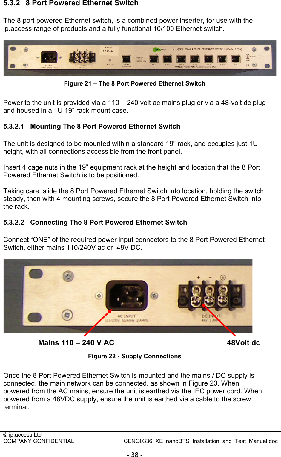
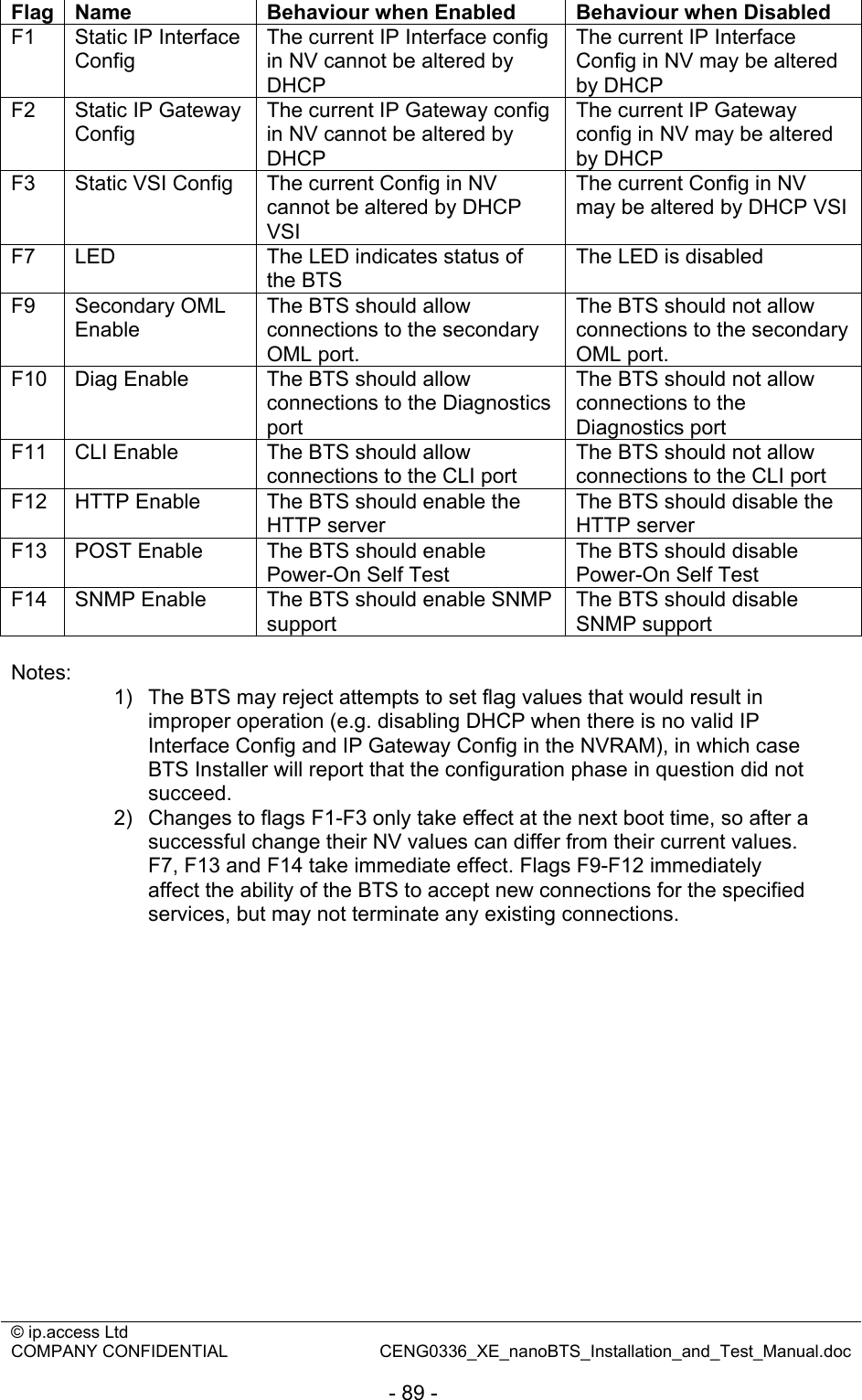
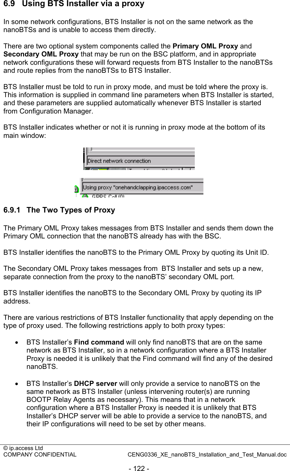
![© ip.access Ltd COMPANY CONFIDENTIAL CENG0336_XE_nanoBTS_Installation_and_Test_Manual.doc - 32 - 4.9 LED Status Indicators The following table shows the meaning of the state LED under normal and fault conditions. State Pattern When Precedence LED_SELF_TEST_FAILURE Red Steady In boot or application code when a power on self-test fails. 1 (High) LED_UNSPECIFIED_FAILURE Red Steady On s/w fatal errors. 2 LED_NO_ETHERNET Orange Slow Flash Ethernet disconnected. 3 LED_FACTORY_RESET Red Fast Blink Dongle detected at start up and the factory defaults have been applied. 4 LED_NOT_CONFIGURED Alternating Red/Green Fast Flash The unit has not been configured. 5 LED_DOWNLOADING_CODE Orange Fast Flash Code download procedure is in progress. 6 LED_ESTABLISHING_XML Orange Slow Blink A management link has not yet been established but is needed for the TRX to become operational. Specifically: for a master a Primary OML or Secondary OML is not yet established; for a slave an IML to its master or a Secondary OML is not yet established. 7 LED_SELF_TEST Orange Steady From power on until end of backhaul power on self-test 8 LED_NWL_TEST Green Fast Flash OML established, NWL test in progress 9 LED_OCXO_CALIBRATION Alternating Green/Orange Slow Blink The unit is in the fast calibrating state [SYNC]. 10 LED_NOT_TRANSMITTING Green Slow Flash The radio carrier is not being transmitted. 11 LED_OPERATIONAL Green Steady Default condition if none of the above apply. 12 (Low)](https://usermanual.wiki/ip-access/KU02ZZR/User-Guide-978921-Page-32.png)


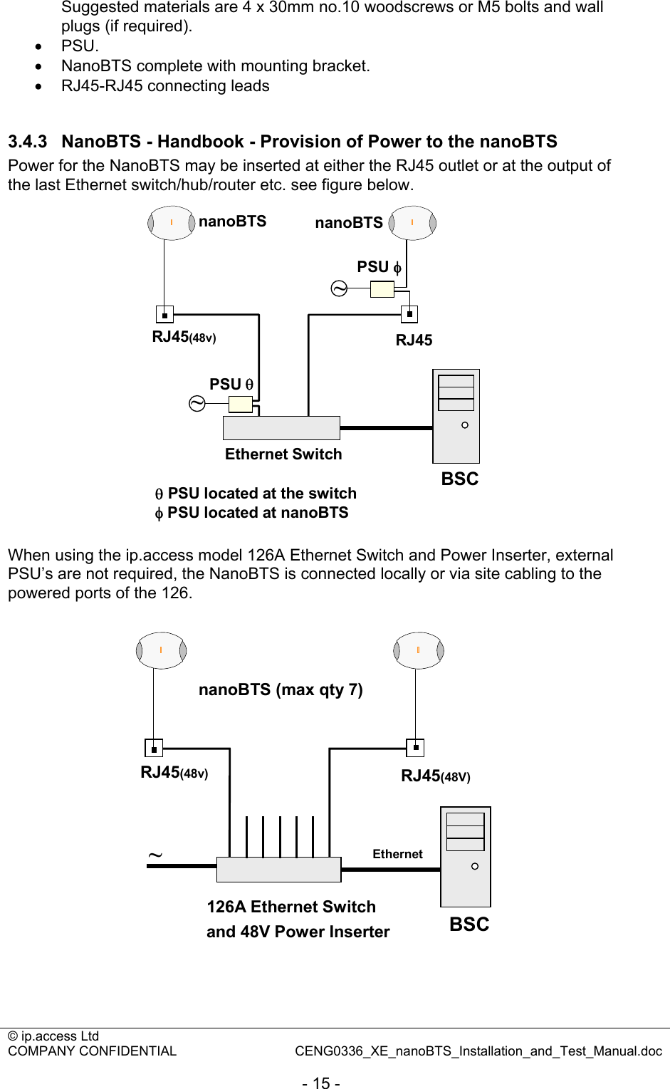
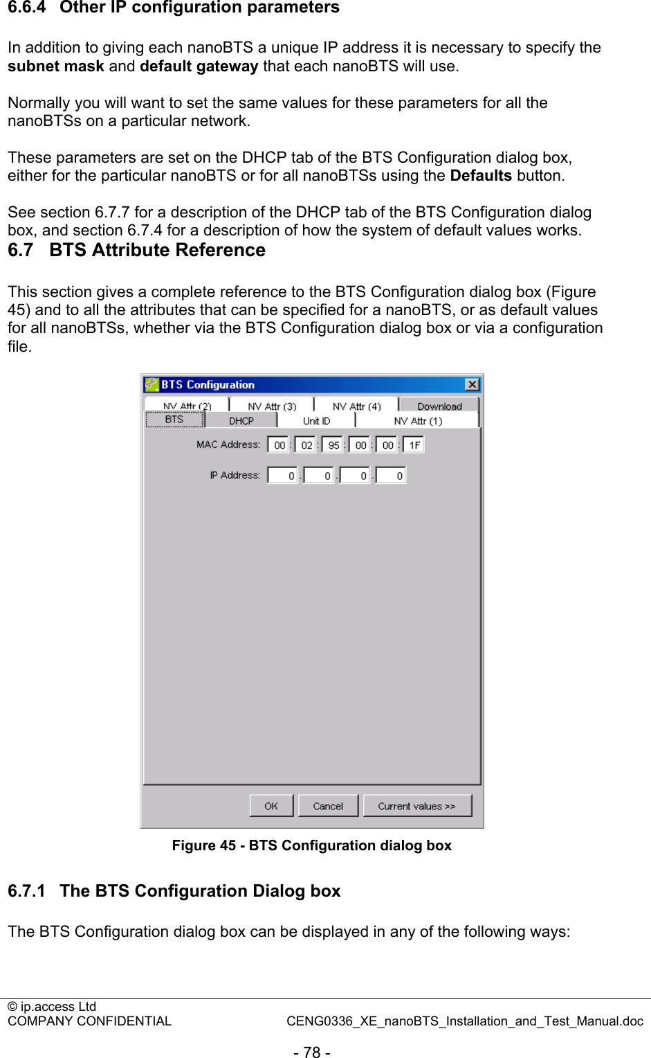
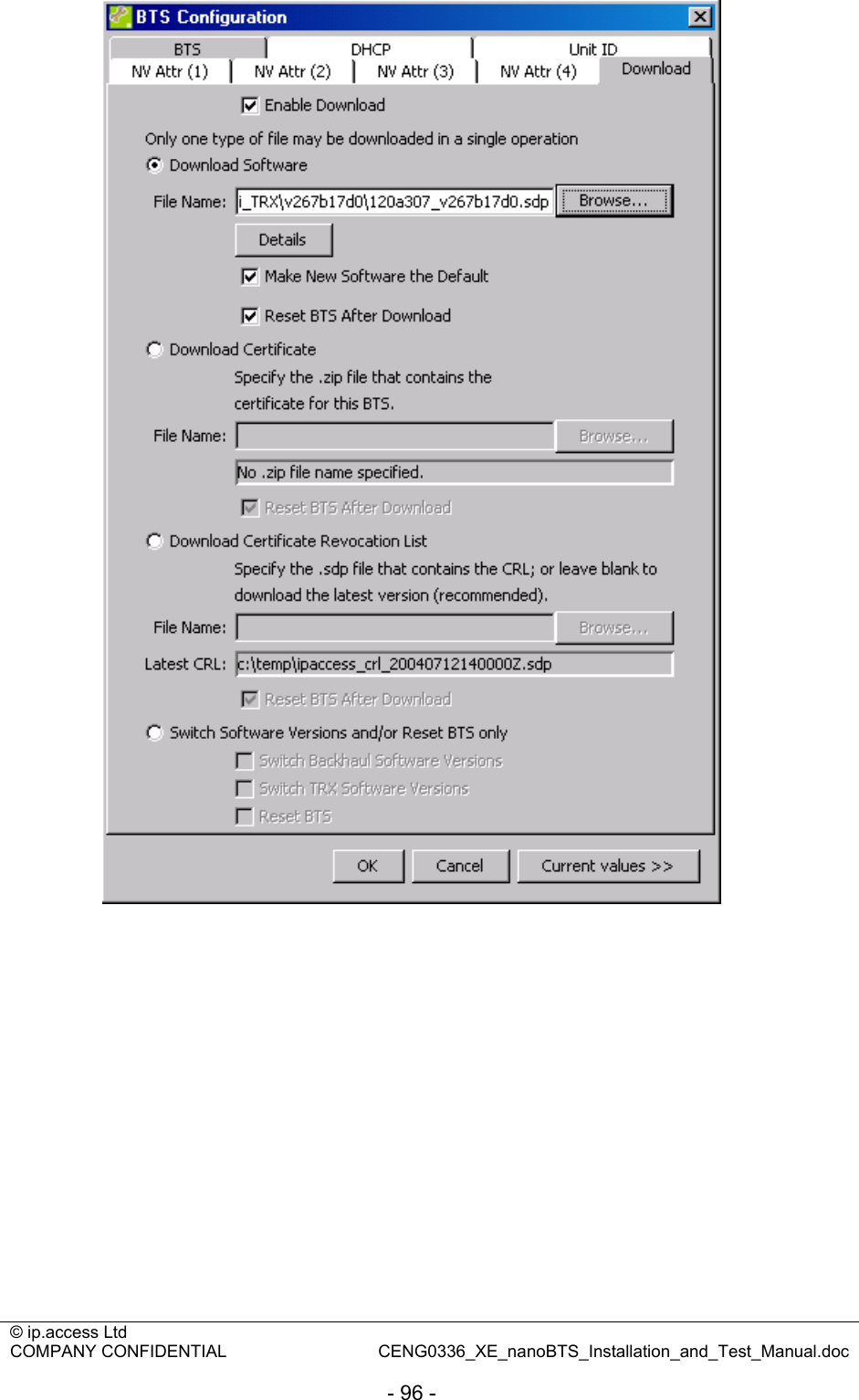
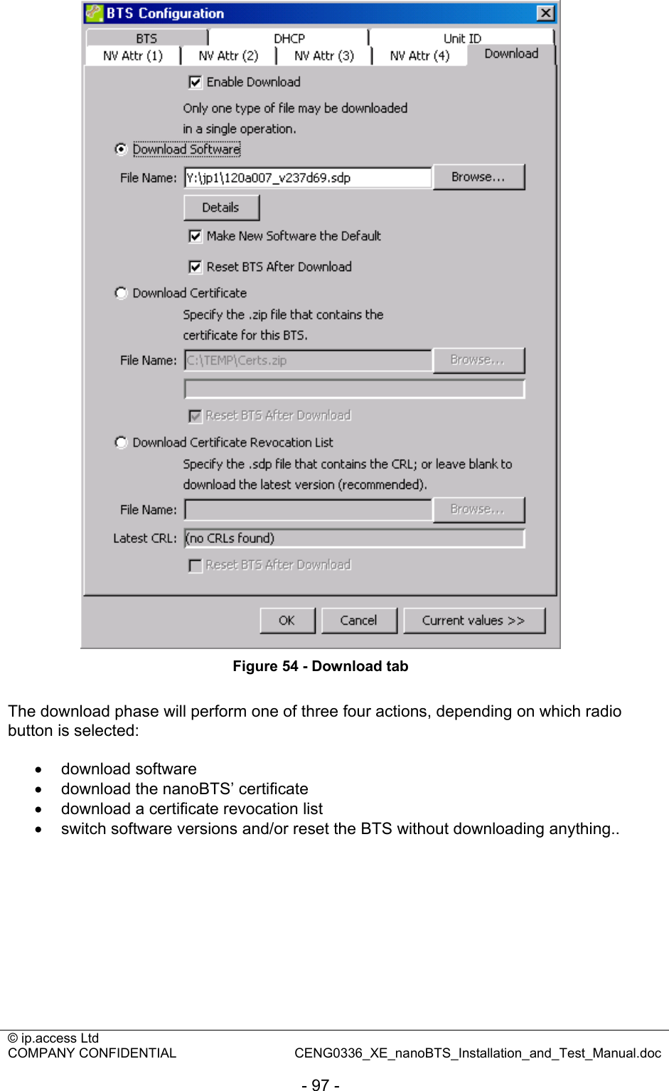
![© ip.access Ltd COMPANY CONFIDENTIAL CENG0336_XE_nanoBTS_Installation_and_Test_Manual.doc - 40 - 6 BTS Installer User Guide (CENG0048) 6.1 Introduction 6.1.1 Purpose and Scope The purpose of this document is to provide the user of the ip.access software package, “BTS Installer”, with the knowledge to use the application to its full potential. Using BTS Installer, the user is able to configure (and reconfigure) nanoBTS™ installation parameters, download new software to nanoBTSs and perform Network Listen tests. This document covers only those aspects of nanoBTS installation that involve using BTS Installer. For full details of how to install a nanoBTS, please refer to [CENG0336]. 6.1.2 Related Documents [CENG0336] CENG0336, “nanoBTS Installation and Test Manual”, ip.access (latest issue) 6.2 Capabilities BTS Installer contains a collection of related tools that enable you to: • Perform initial installation and manual configuration of nanoBTSs. • Upgrade and reconfigure nanoBTSs. • Perform Network Listen tests. These include all the operations necessary to install and configure a nanoBTS to the stage where it will connect correctly to a BSC, from which point its telecommunications behaviour can be configured using management software. Before a nanoBTS can connect to a BSC: • It must have an IP address, and other IP configuration parameters must be set. • It must have a Unit ID, as this is what it uses to identify itself to the BSC. • It must have various non-volatile attributes configured; as a minimum it must know where to find the BSC before it can connect to it. At various times, either during initial installation of a nanoBTS or after it has already been operational for a while, it may be necessary to: • Change the nanoBTS’ IP configuration, Unit ID or non-volatile attributes. • Download a new version of software to the nanoBTS. • Perform various diagnostic operations on the nanoBTS, such as querying its current configuration. A nanoBTS can optionally communicate with the BSC via a secure SSL link. To configure it to do so it is necessary to: • Download a certificate to the nanoBTS](https://usermanual.wiki/ip-access/KU02ZZR/User-Guide-978921-Page-40.png)
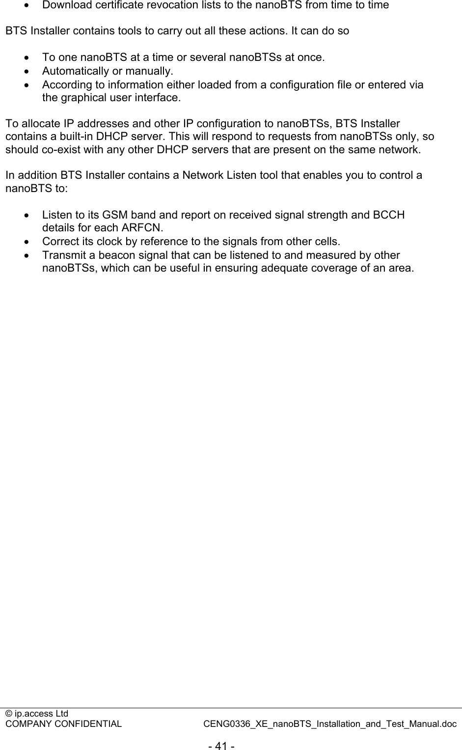
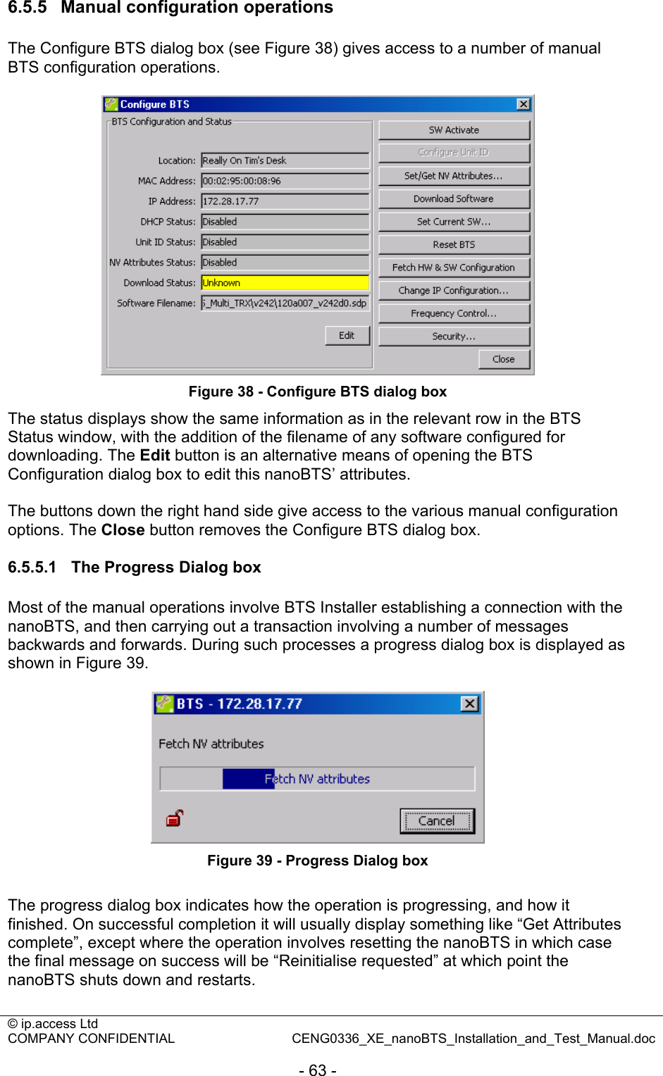
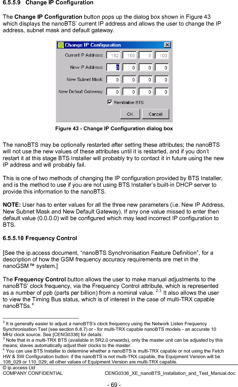
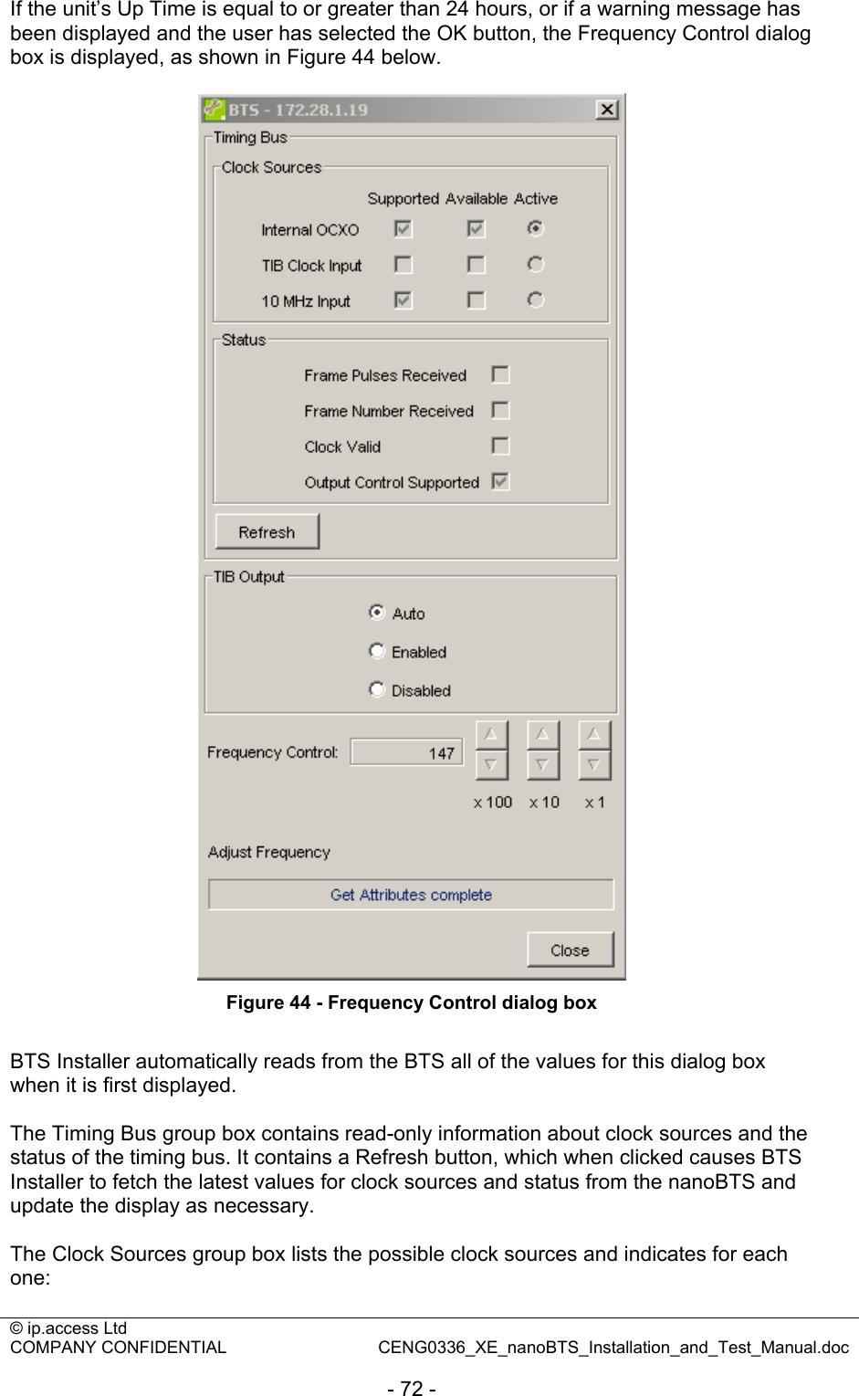
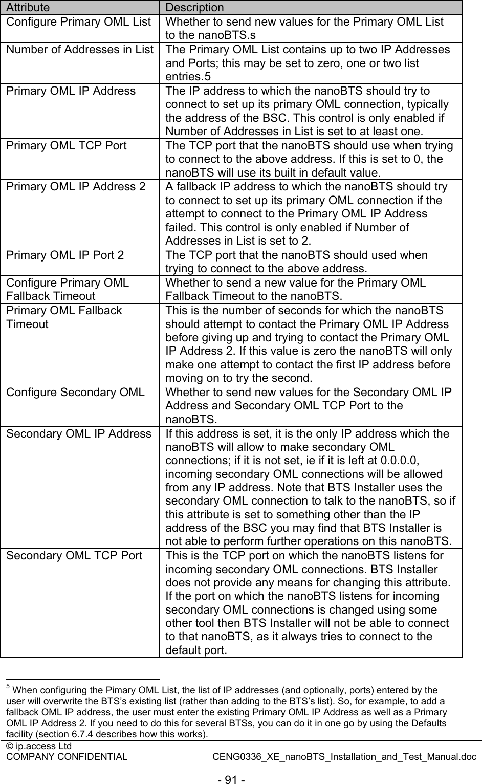
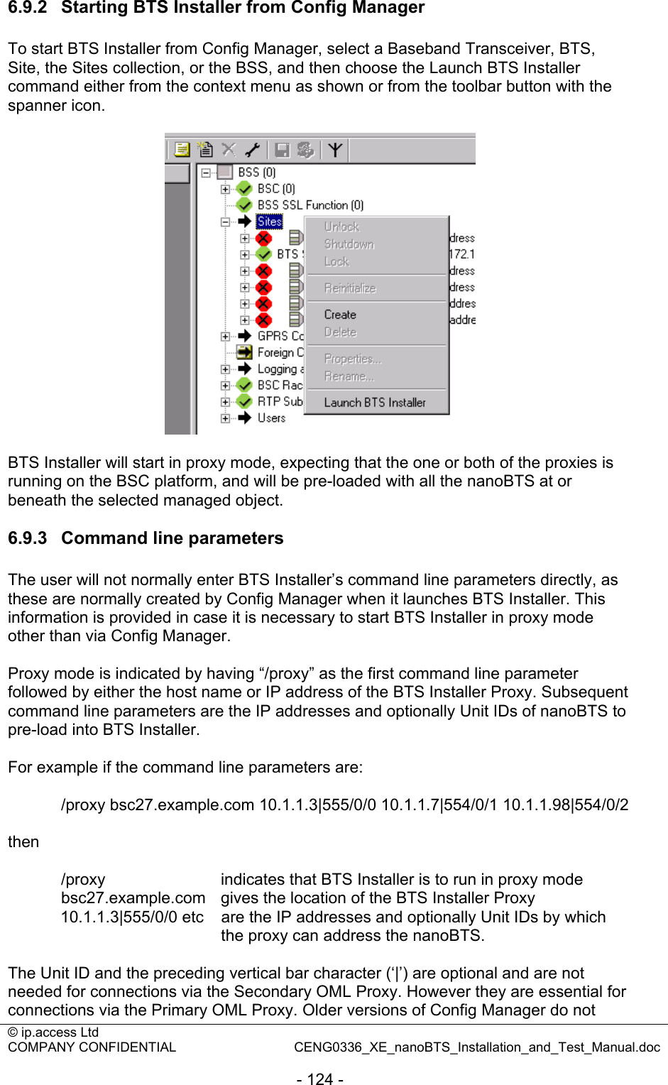
![© ip.access Ltd COMPANY CONFIDENTIAL CENG0336_XE_nanoBTS_Installation_and_Test_Manual.doc - 69 - 6.5.5.9 Change IP Configuration The Change IP Configuration button pops up the dialog box shown in Figure 43 which displays the nanoBTS’ current IP address and allows the user to change the IP address, subnet mask and default gateway. Figure 43 - Change IP Configuration dialog box The nanoBTS may be optionally restarted after setting these attributes; the nanoBTS will not use the new values of these attributes until it is restarted, and if you don’t restart it at this stage BTS Installer will probably try to contact it in future using the new IP address and will probably fail. This is one of two methods of changing the IP configuration provided by BTS Installer, and is the method to use if you are not using BTS Installer’s built-in DHCP server to provide this information to the nanoBTS. NOTE: User has to enter values for all the three new parameters (i.e. New IP Address, New Subnet Mask and New Default Gateway). If any one value missed to enter then default value (0.0.0.0) will be configured which may lead incorrect IP configuration to BTS. 6.5.5.10 Frequency Control [See the ip.access document, “nanoBTS Synchronisation Feature Definition”, for a description of how the GSM frequency accuracy requirements are met in the nanoGSM™ system.] The Frequency Control button allows the user to make manual adjustments to the nanoBTS’ clock frequency, via the Frequency Control attribute, which is represented as a number of ppb (parts per billion) from a nominal value. 2,3 It also allows the user to view the Timing Bus status, which is of interest in the case of multi-TRX capable nanoBTSs.4 2 It is generally easier to adjust a nanoBTS’s clock frequency using the Network Listen Frequency Synchronisation Test (see section 6.8.7) or - for multi-TRX capable nanoBTS models - an accurate 10 MHz clock source. See [CENG0336] for details. 3 Note that in a multi-TRX BTS (available in SR2.0 onwards), only the master unit can be adjusted by this means; slaves automatically adjust their clocks to the master. 4 You can use BTS Installer to determine whether a nanoBTS is multi-TRX capable or not using the Fetch HW & SW Configuration button: if the nanoBTS is not multi-TRX capable, the Equipment Version will be 108_029 or 110_029; all other values of Equipment Version are multi-TRX capable.](https://usermanual.wiki/ip-access/KU02ZZR/User-Guide-978921-Page-69.png)
![© ip.access Ltd COMPANY CONFIDENTIAL CENG0336_XE_nanoBTS_Installation_and_Test_Manual.doc - 82 - nanoBTS, as it is the IP address that BTS Installer will use to contact each nanoBTS for later configuration phases. In addition, when BTS Installer connects to a BTS via a Primary OML Proxy, BTS Installer identifies the nanoBTS it wants to talk to by quoting the Unit ID to the proxy, so in this case it is the Unit ID that is the most useful identifier for the nanoBTS. See section 6.9 for more information about proxy mode. BTS Installer does not therefore require that any of these parameters have unique values, as to do so would restrict the usefulness of the tool in some circumstances. 6.7.4 How Defaults Work You do not need to enter a value for every parameter for every nanoBTS to be configured; most parameter values can be picked up using BTS Installer’s system for handling default values. When BTS Installer wants to know the value of a parameter to apply to a particular nanoBTS: • First it will look in the BTS Database entry for that nanoBTS, to see whether a value has been specified explicitly for that nanoBTS, either in a [BTS:<location>] section in the configuration file or manually via the user interface; • If it doesn’t find an explicit value for that nanoBTS it will look at a special “default” BTS Database entry, which the user can set in the [Default] section in the configuration file or via the Defaults button on the user interface • If the user hasn’t specified a Default value then a built-in default value will be used. The built-in default values are mostly things like zero, null strings, “off” or “don’t”. If the user specifies no parameters at all then BTS Installer will do nothing at all, and thus will do nothing harmful. In a typical installation there will be several parameters which will have the same settings for all nanoBTS, for example the router (default gateway) DHCP parameter. The user is recommended to set these as default values using the [Default] section in the configuration file or the Defaults button on the user interface; it will not then be necessary to specify these values separately for each nanoBTS. Note however that if you use the Edit button (or some other means) to edit the configuration for a nanoBTS what you will see in the dialog box is not just the parameters you have specified explicitly for this nanoBTS but the result of merging values from all three of the sources above. If you change a default value using the Defaults button then you will change what you see in the dialog box for those nanoBTSs that do not have an explicit setting for this parameter. 6.7.5 Enabling Configuration Phases The various configuration phases can be enabled and disabled separately, and whether each phase is enabled or disabled is indicated by the various tabs of the BTS Configuration dialog box, which are grey if the relevant phase is enabled or white if the relevant phase is disabled.](https://usermanual.wiki/ip-access/KU02ZZR/User-Guide-978921-Page-82.png)
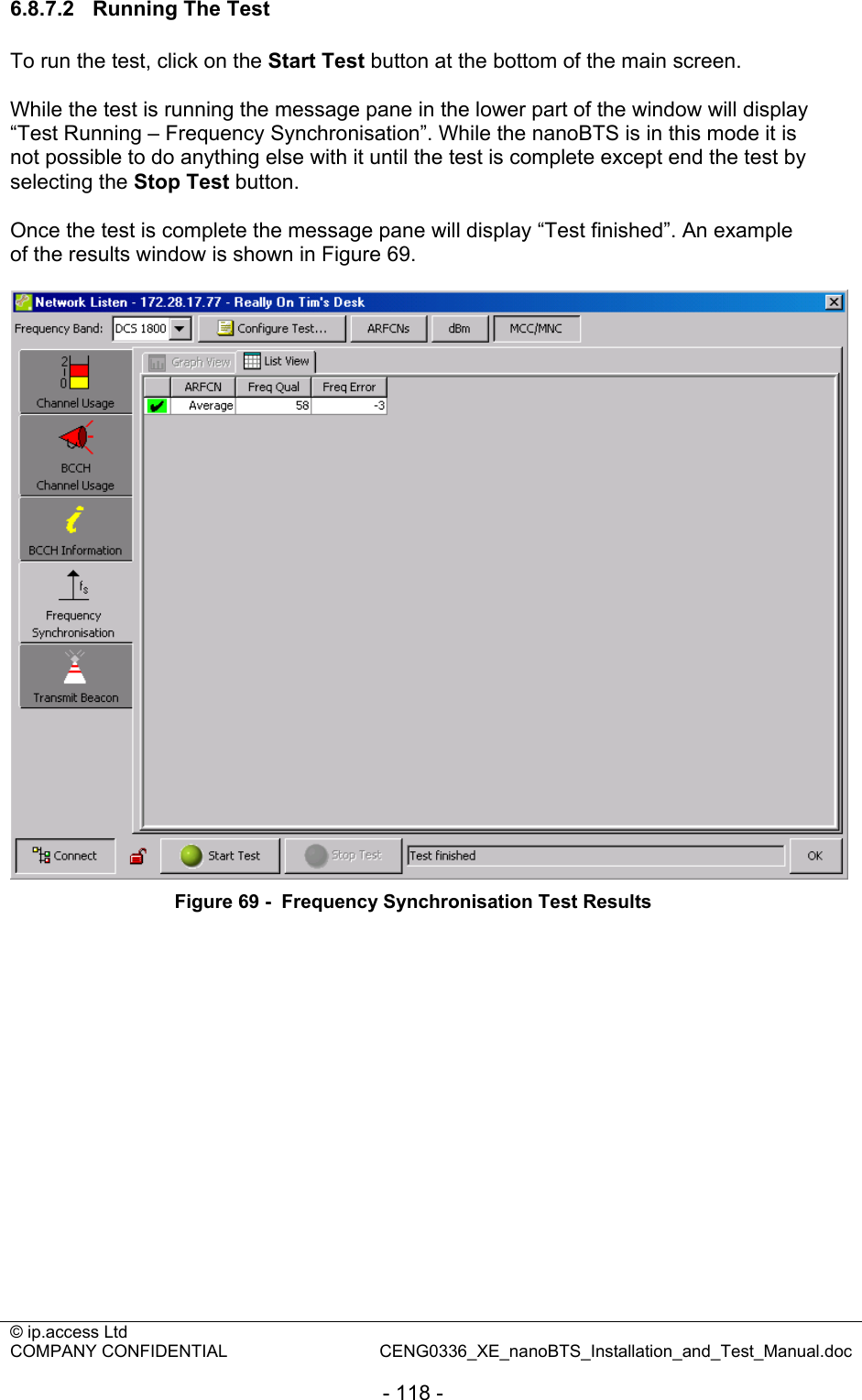
![© ip.access Ltd COMPANY CONFIDENTIAL CENG0336_XE_nanoBTS_Installation_and_Test_Manual.doc - 115 - 6.8.7 Frequency Synchronisation Test The Frequency Synchronisation test uses the nanoBTS’s NWL downlink receiver to monitor one or more GSM RF channels, and if suitable BCCH carriers are found, measure the frequency error of the local oscillator relative to the measured references. The user can choose whether the frequency errors should be combined or reported separately in the event that more than one BCCH carrier is found. The user can also choose whether the nanoBTS should use the result of the test to adjust the local oscillator to correct the error. Note that a nanoBTS can only adjust its clock using this test if the Internal OCXO is the active clock source. If the Internal OCXO is not the active clock source: • If the nanoBTS being adjusted is a master, remove its 10 MHz input. • If the nanoBTS being adjusted is a slave, either remove the cable from its TIB In port, or use BTS Installer to temporarily disable the TIB Out of its master. If the user attempts to perform a Frequency Synchronisation test with the “Adjust the clock to correct the reported errors” option on nanoBTS that has an active external clock source, BTS Installer displays an error message indicating that in order to perform this test, the internal OCXO must be the active clock source.6 PRIOR TO CALIBRATION THE nanoBTS SHOULD BE POWERED UP FOR A MINIMUM OF 10 MINUTES TO ALLOW IT TO STABILISE Note that the nanoBTS may not be able to correct the frequency error in one go, so you may need to re-run this test a few times to get the error down to a reasonable level. For further information on using the Frequency Synchronisation test to calibrate a nanoBTS’s local oscillator, please refer to [CENG0336]. Note that in the event that no BCCH carriers can be found, the nanoBTS’s local oscillator can be adjusted manually, as described in section 6.5.5.10. As with the BCCH Information test, if the BCCH Usage test has already been run, BTS Installer automatically uses the results of that test to populate the ARFCN White List for this test. When viewing the configuration of the test, you will see that the ARFCN White list has automatically been selected as those detected with a BCCH. You can override this if you wish. To use this test select the Frequency Synchronisation tab on the left hand side of the Network Listen window. Then, if you wish to view or change the configuration for the test, select the Configure Test button located at the top of the screen. 6 If BTS Installer finds that the Internal OXCO is the active clock source and tries to initiate the test, but in the meantime an external clock source has become active, the nanoBTS rejects the test request and BTS Installer displays an error message indicating “resource not available”.](https://usermanual.wiki/ip-access/KU02ZZR/User-Guide-978921-Page-115.png)
![© ip.access Ltd COMPANY CONFIDENTIAL CENG0336_XE_nanoBTS_Installation_and_Test_Manual.doc - 129 - 6.11 Configuration File Reference This section defines the format and contents of the configuration file. The configuration file is an ASCII text file that can be created with any text editor. Whilst it is expected to be normal practice that a configuration file will be prepared in advance of an installation job, BTS Installer can carry out most of its functions without a configuration file, and can write out the contents of the BTS Database to a new configuration file (so you can use BTS Installer to create configuration files instead of a text editor). 6.11.1 File format Comments start with ';' or '*'. You can't use these characters at all in parameter names or values - there is no escape mechanism. Spaces and case are not significant (apart from inside string values - whether string values themselves are case sensitive depends on what they're used for). Blank lines are ignored. The format is a bit, but not quite, like .ini file format. Sections are introduced by a heading in square brackets; data items mostly consist of a name, an equals sign and a value. A section called [Defaults] may be present and specifies default values for BTS configuration parameters; all BTSs will use these values unless otherwise specified. To specify the parameters for a particular BTS use the section heading: [BTS:<location>] where <location> is the Location string as to be stored in the NVRAM, for example: [ BTS : Room G47 ] ; where this BTS lives Leading and trailing spaces and comments are ignored so that's the same as: [BTS:Room G47] The <location> may be blank but the colon must still be present, as in: [BTS:] (The location string can't contain a ']' - there is no escape mechanism.) Within a section parameters are given like this: [Defaults] Router=192.168.0.1 SubnetMask = 255.255.255.0 PrimaryOmlTcpPort = 3002 [ BTS : Somewhere else ] IPAddress = 192.168.0.2](https://usermanual.wiki/ip-access/KU02ZZR/User-Guide-978921-Page-129.png)
![© ip.access Ltd COMPANY CONFIDENTIAL CENG0336_XE_nanoBTS_Installation_and_Test_Manual.doc - 130 - BTSID = 123 ; comments are allowed after values TRXID = 456 6.11.2 Data types Parameters can be: • numbers (positive or negative integers), • arbitrary strings (except they can't contain ';' or '*' and can't have leading or trailing spaces); strings are not quoted • boolean values ("yes", "true", "t", "1"; "no", "false", "f", "0") (without the quotes); if the value is omitted it's taken as true • flag values - these are used for the non-volatile configuration flags and can have the same values as boolean values but also "on" or "set", "off" or "clear", or, to indicate that the flag value should not be sent to the BTS, "notset", "unknown" or "invalid" • IP address - normal dotted quad notation (actually host names might work sometimes, but will get translated to numeric IP address which are what will get sent to the BTS) • MAC address - six two digit hex numbers separated by colons • unit id – three numbers separated by slashes, being <site id>/<BTS id>/<TRX id>, for example 862/0/0 • percentage – an alarm threshold percentage value, either a number from –20 to 120 or the string OFF indicating that this alarm is switched off As a special case, in the [Pool] section only, single IP addresses or ranges of IP addresses can be given without any parameter name, eg: 1.2.3.4 1.2.4.1 - 1.2.4.254 6.11.3 Sections Sections in the file can be in any order and the order is not significant. The following sections are allowed: [Pool] Values are IP addresses or ranges, in the format noted above, that the DHCP server will use as a pool from which to allocated addresses to any BTSs which do not have explicit IP addresses assigned [Default] Default parameters for BTS configuration [BTS:<location>] Parameters for a specific BTS as noted above](https://usermanual.wiki/ip-access/KU02ZZR/User-Guide-978921-Page-130.png)
![© ip.access Ltd COMPANY CONFIDENTIAL CENG0336_XE_nanoBTS_Installation_and_Test_Manual.doc - 131 - [UnknownBts] Parameters for any BTS which asks for an IP address; if this section is present no BTS sections may also be present. See section 6.3.3.2 for a description of BTS Installer’s Unknown BTS Mode. Warning: use this mode with care! 6.11.4 BTS configuration parameters Parameter names are case insensitive, so the following are all equivalent: subnetmask = 255.255.255.0 SubnetMask = 255.255.255.0 Subnetmask = 255.255.255.0 The order in which parameters are specified within a section is not significant. If the same parameter is specified more than once in a section then which value BTS Installer will use is not defined. The following boolean parameters control which configuration phases will run: DHCP The DHCP configuration phase will run to supply the IP address etc to this nanoBTS ConfigureUnitId The Unit ID configuration phase will run to set the nanoBTS’ Unit ID. NVRAM The non-volatile attribute configuration phase will run (note that you will also need to set additional boolean parameters to indicate which NVRAM values should and should not be sent to the nanoBTS, see below) Download BTS Installer will download software to the nanoBTS Example: [Defaults] dhcp = yes configureunitid = yes nvram = yes download = yes ; do everything by default ........... [ BTS: old one ] dhcp = no ; just upgrade software on this one, it's nvram = no ; already got the rest of its Config configureunitid = no ........... By default all these are off, ie BTS Installer will do nothing at all, and hence nothing harmful, unless you tell it to. 6.11.5 DHCP Configuration Phase Here is the full list of parameters relating to the DHCP configuration phase:](https://usermanual.wiki/ip-access/KU02ZZR/User-Guide-978921-Page-131.png)
![© ip.access Ltd COMPANY CONFIDENTIAL CENG0336_XE_nanoBTS_Installation_and_Test_Manual.doc - 132 - Name Type What DHCP Boolean whether to run the DHCP configuration phase IpAddress IP address explicit IP address to assign IpLeaseTime number length of IP lease in seconds MacAddress MAC address MAC address of BTS Router IP address IP address of default gateway SubnetMask IP address subnet mask 6.11.6 Unit ID Configuration Phase Here is the full list of parameters relating to the Unit ID configuration phase: Name Type What ConfigureUnitId Boolean whether to run the Unit ID configuration phase NewUnitId unit id enter the new Unit ID value ResetBtsUnitId Boolean whether to reset the nanoBTS after configuring the Unit ID 6.11.7 Non-volatile Attribute Configuration Phase To cause a non-volatile attribute to be sent to the nanoBTS you need to switch on both the overall "nvram" boolean parameter and a specific boolean parameter which specifies a particular group of non-volatile attributes which are set as a unit. (These specific boolean control parameters correspond to the various check boxes on the NV Attr (n) tabs of the BTS Configuration dialog box, see section 6.7.) Control parameter Settings affected SendNvConfigFlags NV config flags F1 to F14 SendPrimaryOmlConfig PrimaryOmlIpAddress, PrimaryOmlTcpPort, PrimaryOmlIpAddress2, PrimaryOmlTcpPort2 SendPrimaryOmlFbTimeout PrimaryOmlFbTimeout SendSecondaryOmlConfig SecondaryOmlIpAddress Sendlocation The BTS' location string as specified in the [BTS] section header. SendUnitName UnitName SendSnmpConfig All Snmp* settings (ie. Settings that start with the characters Snmp, regardless of case) SendAlarmThresholdList InputVoltageLower, InputVoltageUpper, InternalTempLower, InternalTempUpper, InputCurrentLower, InputCurrentUpper, InputPowerLower, InputPowerUpper So in order to persuade BTS Installer to send a unit name string to a BTS during automatic configuration you'll need all of: [ BTS : somewhere ] nvram ; run the NVRAM setting procedure sendunitname ; send the unit name parameter](https://usermanual.wiki/ip-access/KU02ZZR/User-Guide-978921-Page-132.png)
![© ip.access Ltd COMPANY CONFIDENTIAL CENG0336_XE_nanoBTS_Installation_and_Test_Manual.doc - 133 - unitname = FredsBTS ; the unit name to be sent and if you want the "somewhere" to be sent to the BTS as the location string during automatic configuration you'll also need: sendlocation ; send the location string You might want to put nvram, sendunitname and sendlocation just once in the [default] section so only the unit name would need to be specified for each individual BTS. The SNMP parameters are even more complicated, because to cause one of these to be sent to the nanoBTS you need to switch on the overall "nvram" boolean parameter and the specific boolean parameter “sendsnmpconfig” which specifies that some of the SNMP configuration is to be send and another boolean parameter for each of the individual SNMP configuration sub-attributes that you wish to send. Control parameter SNMP sub-attribute affected SendSnmpCommunityString SnmpCommunityString SendSnmpTrapAddress SnmpTrapAddress SendSnmpTrapPort SnmpTrapPort SendSnmpManagerAddress SnmpManagerAddress SendSnmpSystemContact SnmpSystemContact Here is the full list of parameters relating to the non-volatile attribute configuration phase: Name Type What Nvram Boolean whether to run the non-volatile attribute setting configuration phase SendNvConfigFlags Boolean whether to send the NV Configuration Flags F1 Flag NVRAM config flag (see section 6.7.9) ... ... ... F14 Flag NVRAM config flag (see section 6.7.9) FstaticInterfaceIpConfig Flag Synonym for F1 FstaticIpGatewayConfig Flag Synonym for F2 FstaticVsiConfig Flag Synonym for F3 Fled Flag Synonym for F7 FsecondaryOmlEnable Flag Synonym for F9 FdiagEnable Flag Synonym for F10 FcliEnable Flag Synonym for F11 FhttpEnable Flag Synonym for F12 FpostEnable Flag Synonym for F13 FsnmpEnable Flag Synonym for F14 SendPrimaryOmlConfig Boolean Whether to send the next attributes PrimaryOmlListLength Number How many (0, 1 or 2) sets of primary OML address and port to send PrimaryOmlIpAddress IP address primary OML IP address PrimaryOmlTcpPort number primary OML TCP port](https://usermanual.wiki/ip-access/KU02ZZR/User-Guide-978921-Page-133.png)