lantronix PWXC PremierWave XC User Manual 500 598 PremierWave XC UG Release something else
lantronix PremierWave XC 500 598 PremierWave XC UG Release something else
UserManual.wiki
>
lantronix
>
PWXC User Manual
Lantronix PremierWave_XC_UG_Rev3.pdf
Navigation menu
Upload a User Manual
Namespaces
Wiki Guide
HTML
PDF
Info
Views
User Manual
Discussion / Help
Navigation


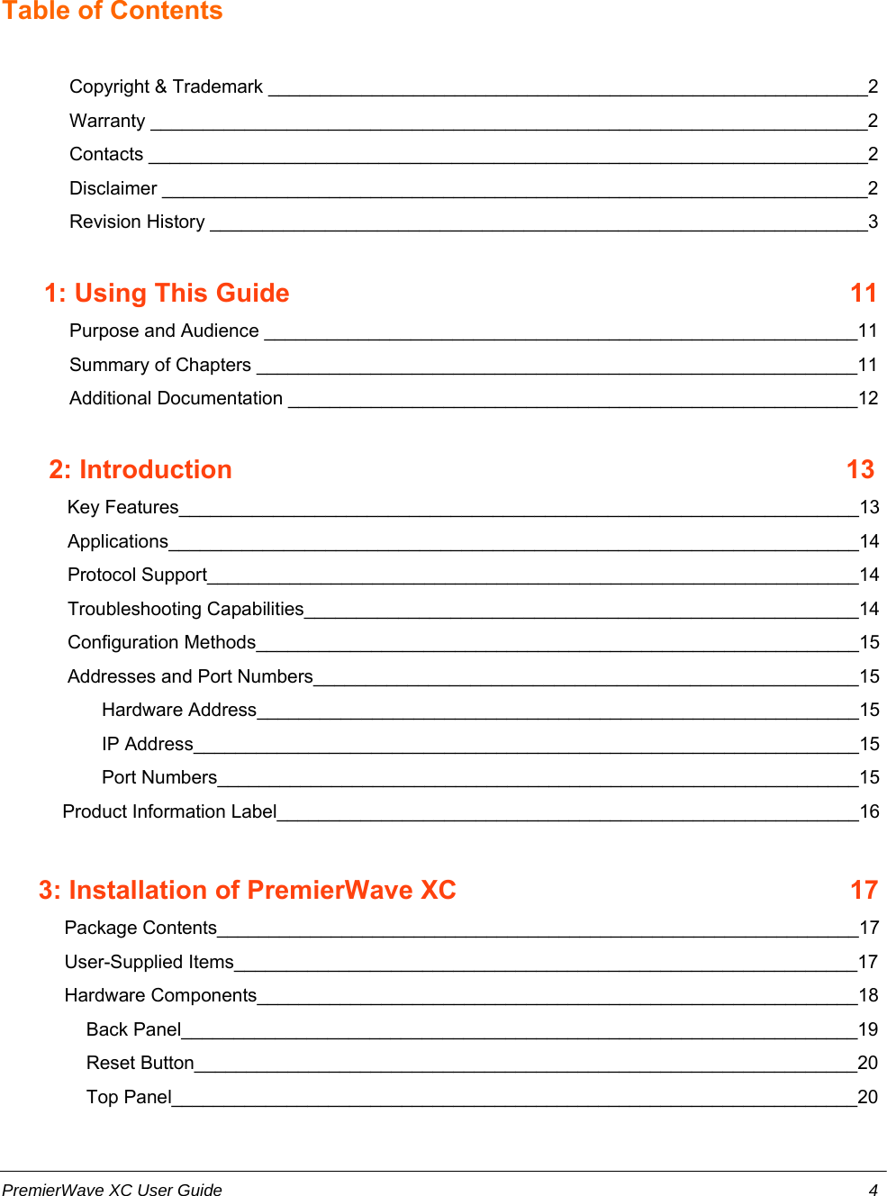
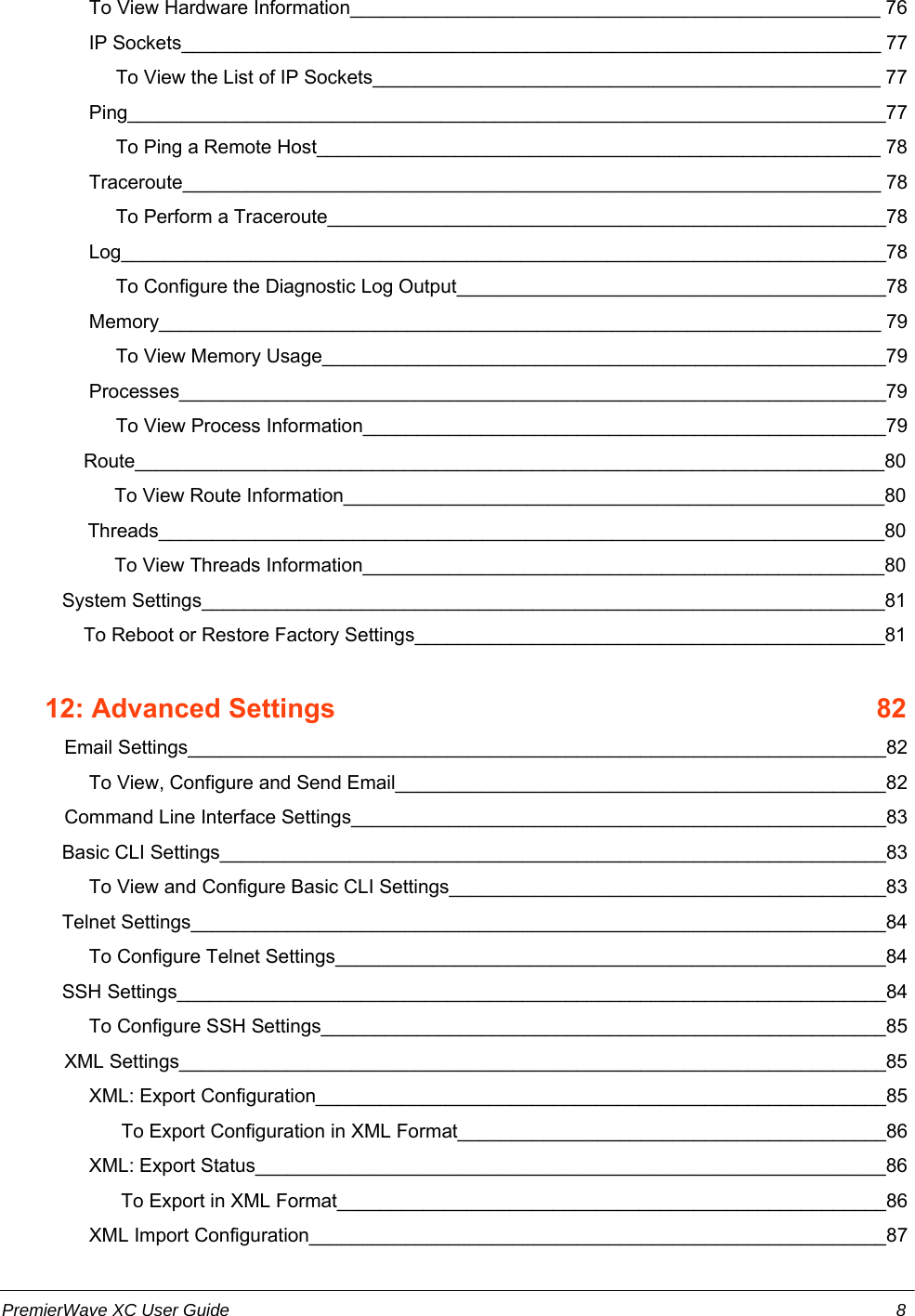
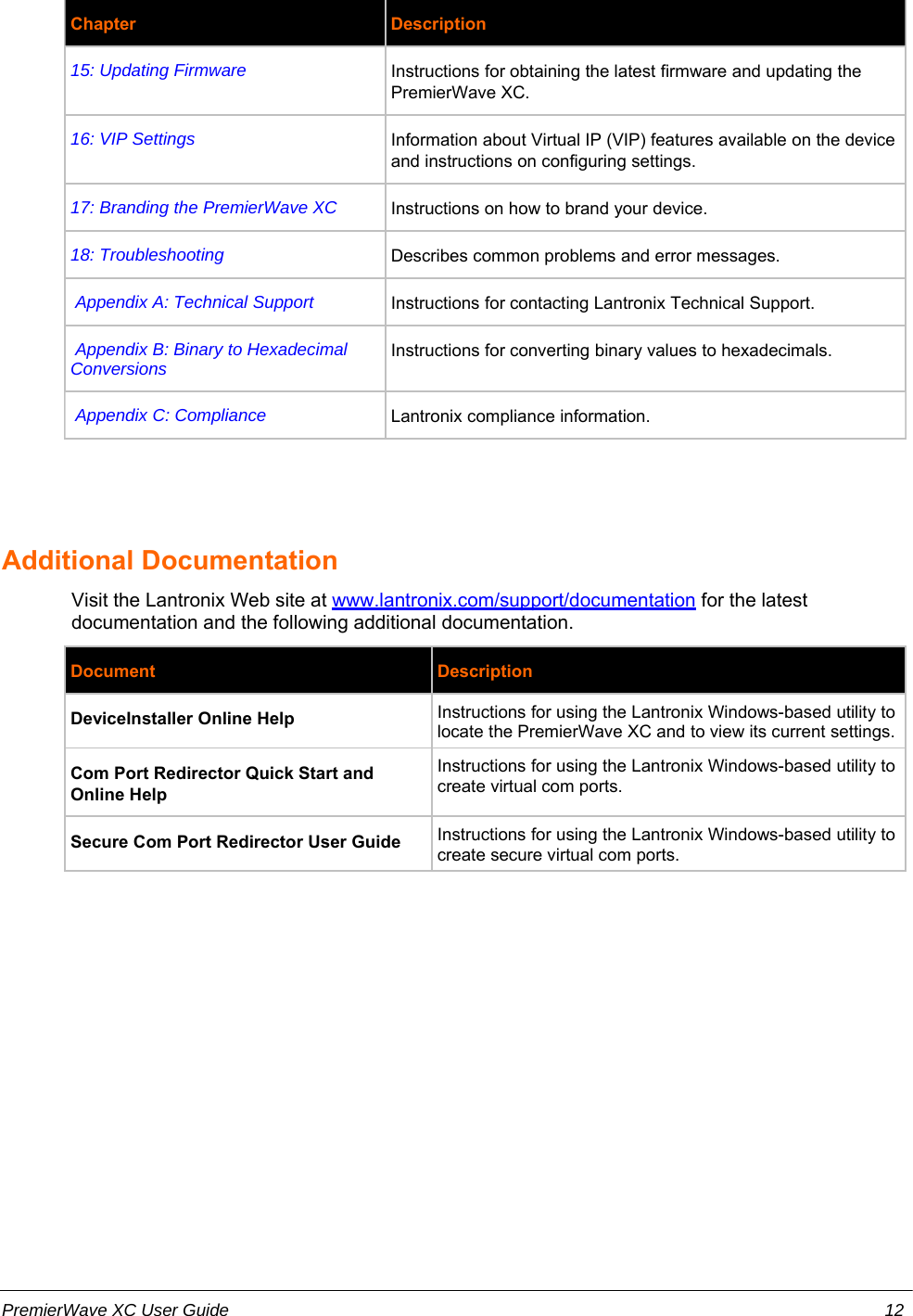

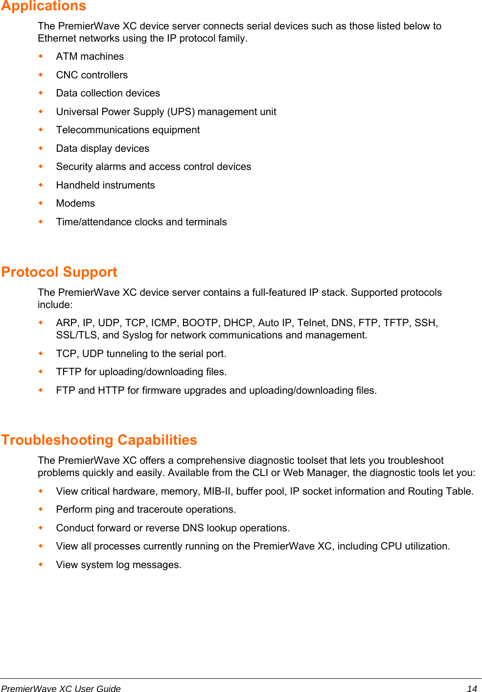
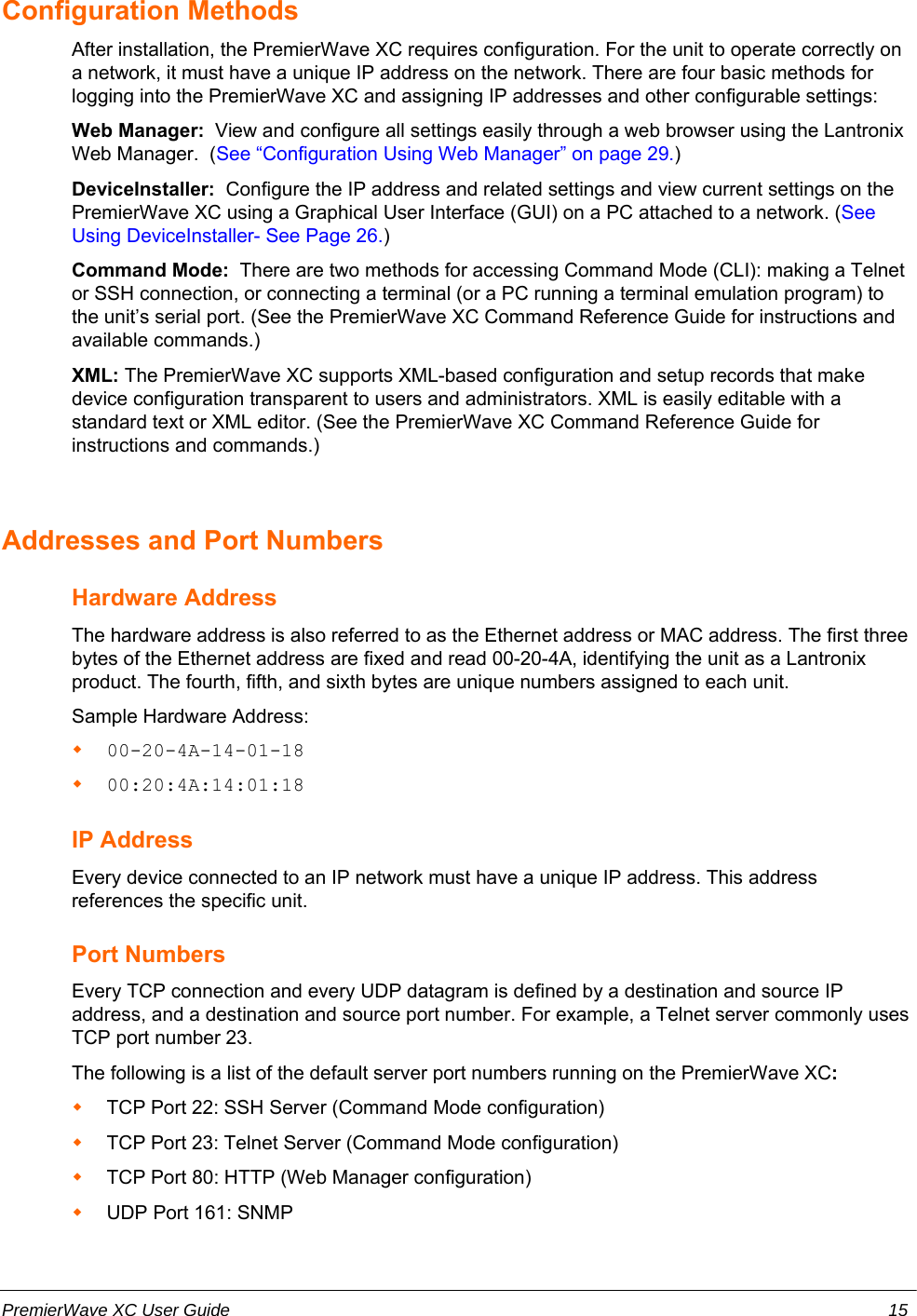
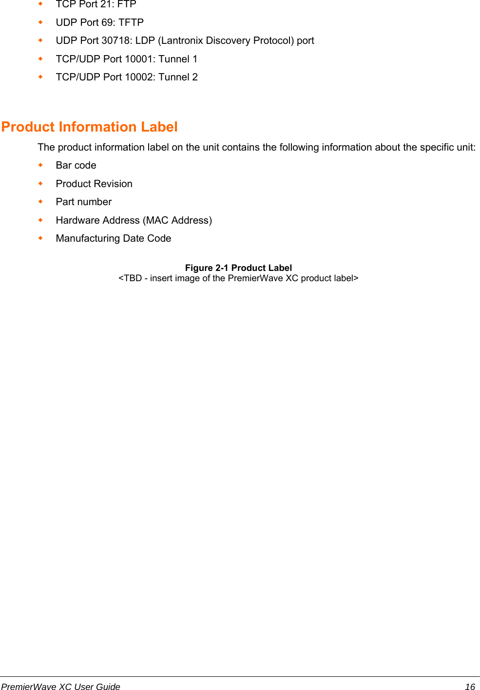

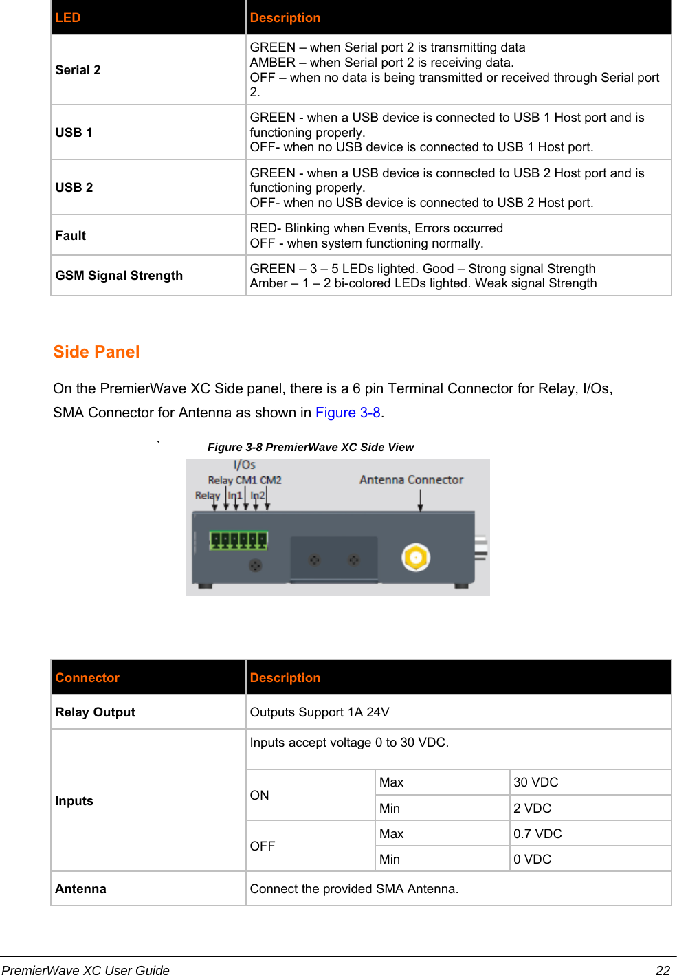

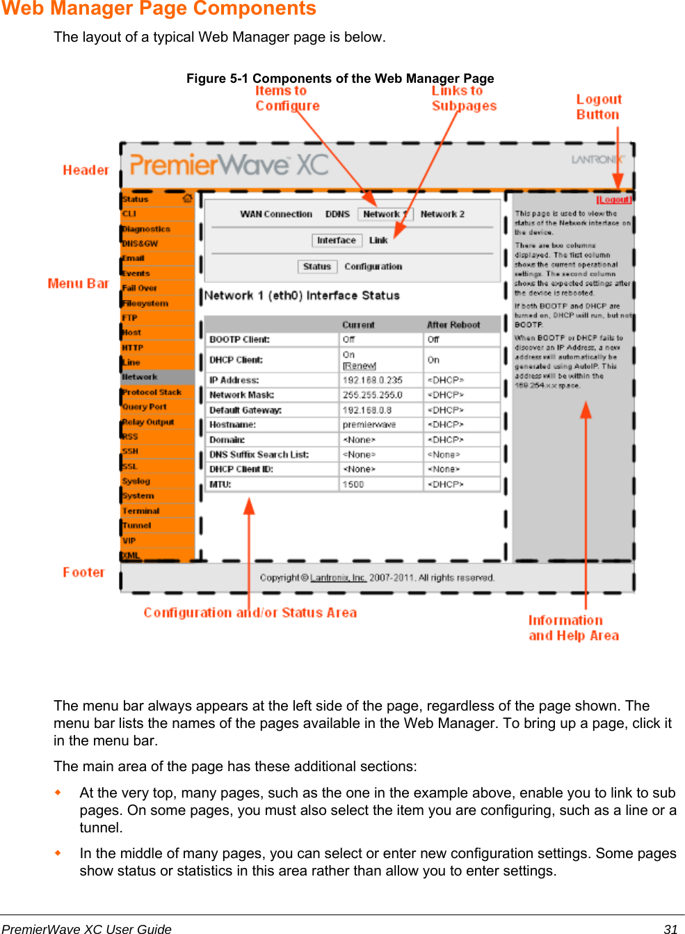

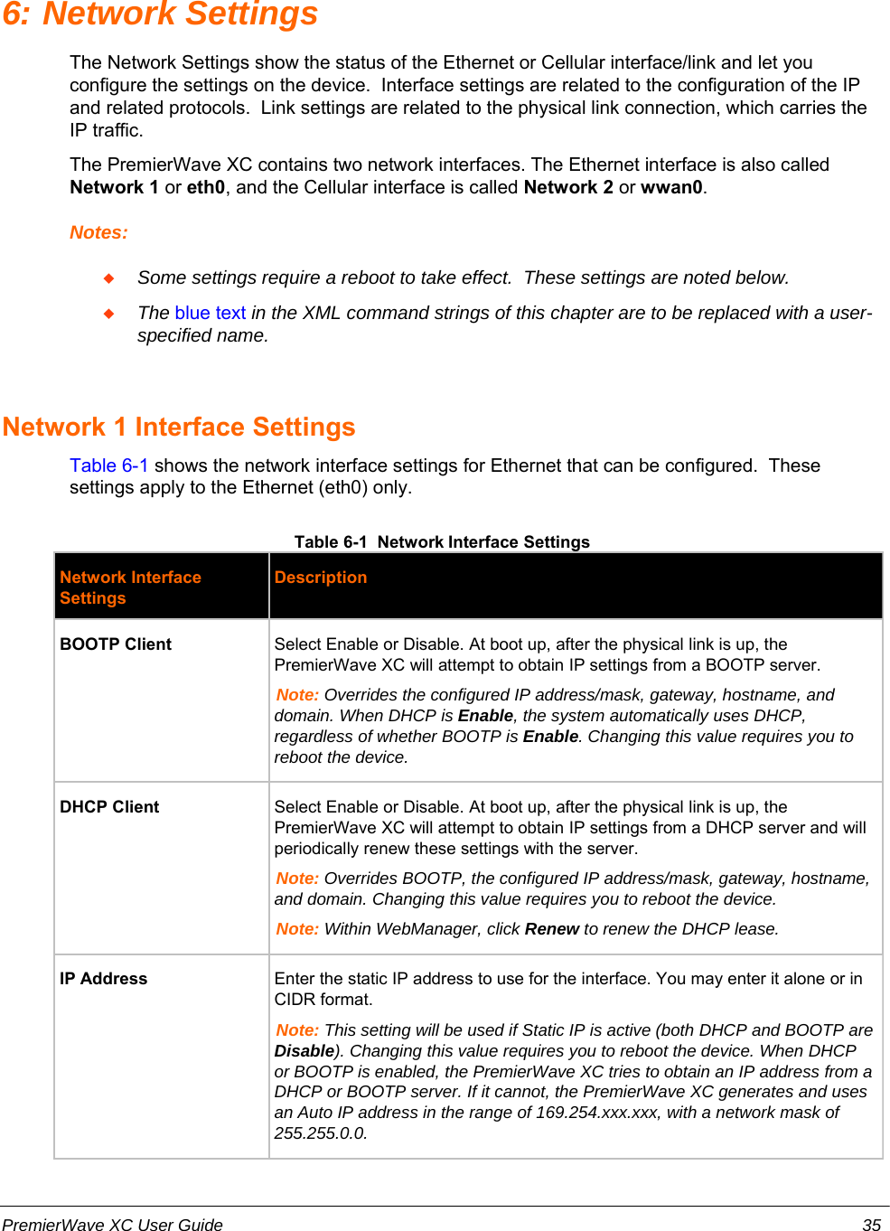
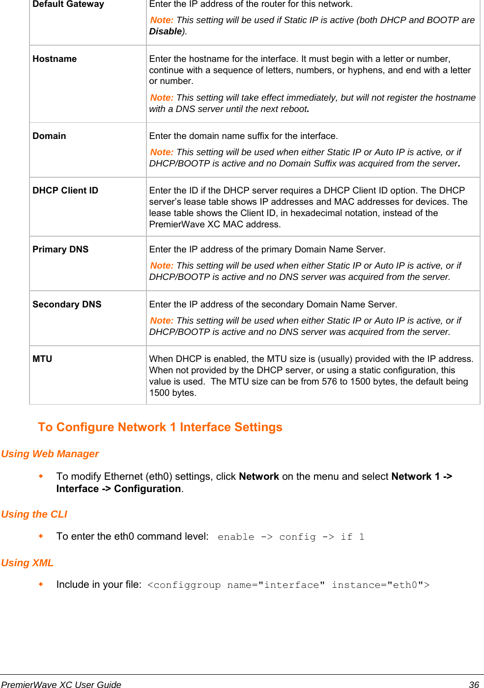
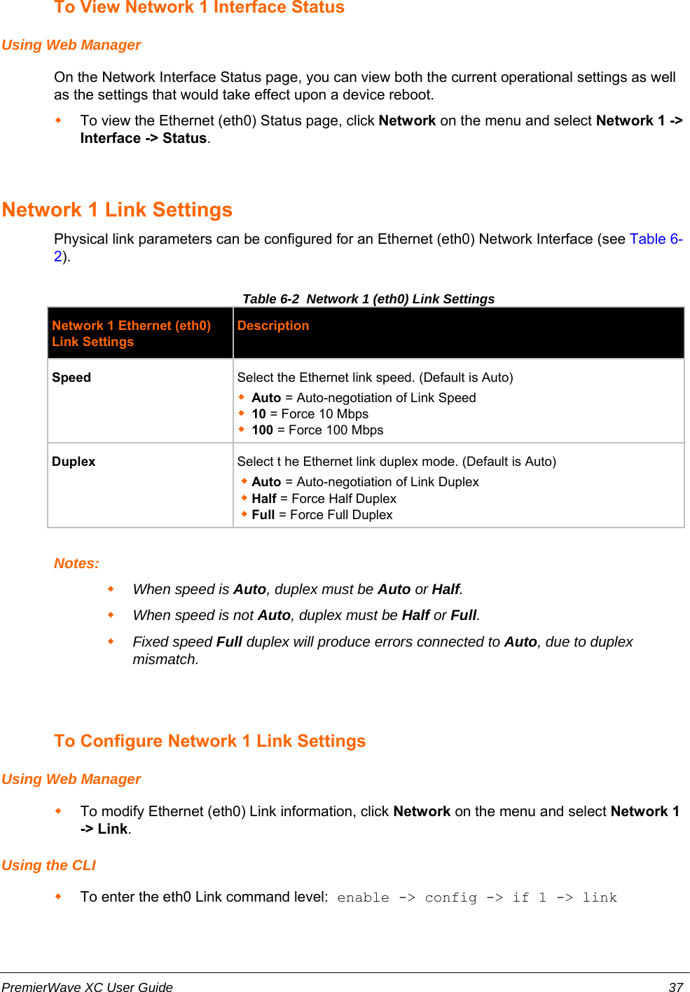
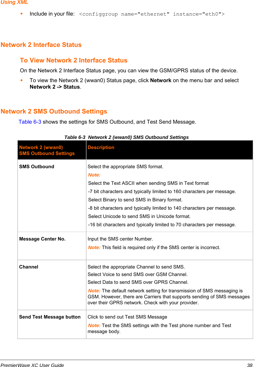
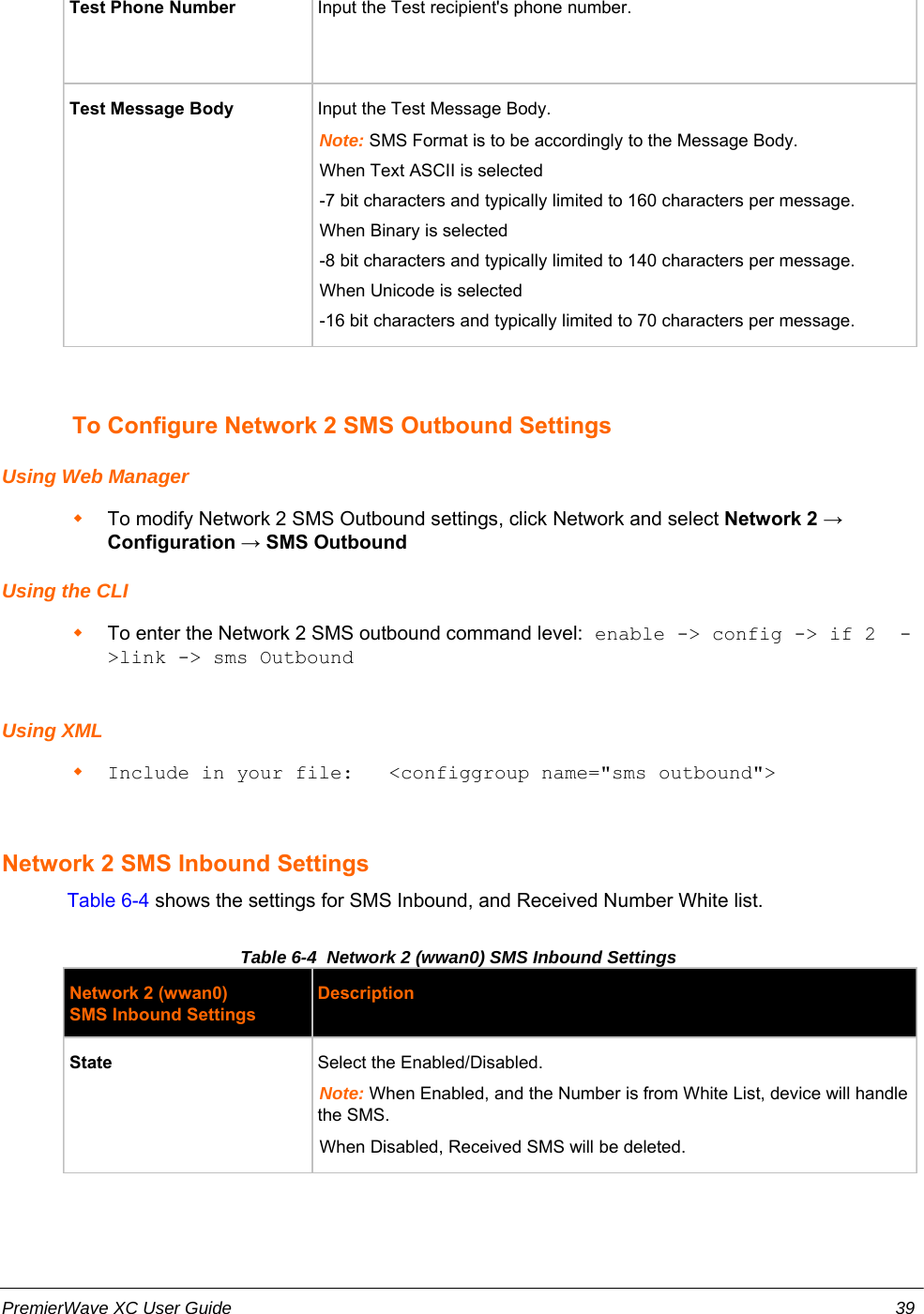
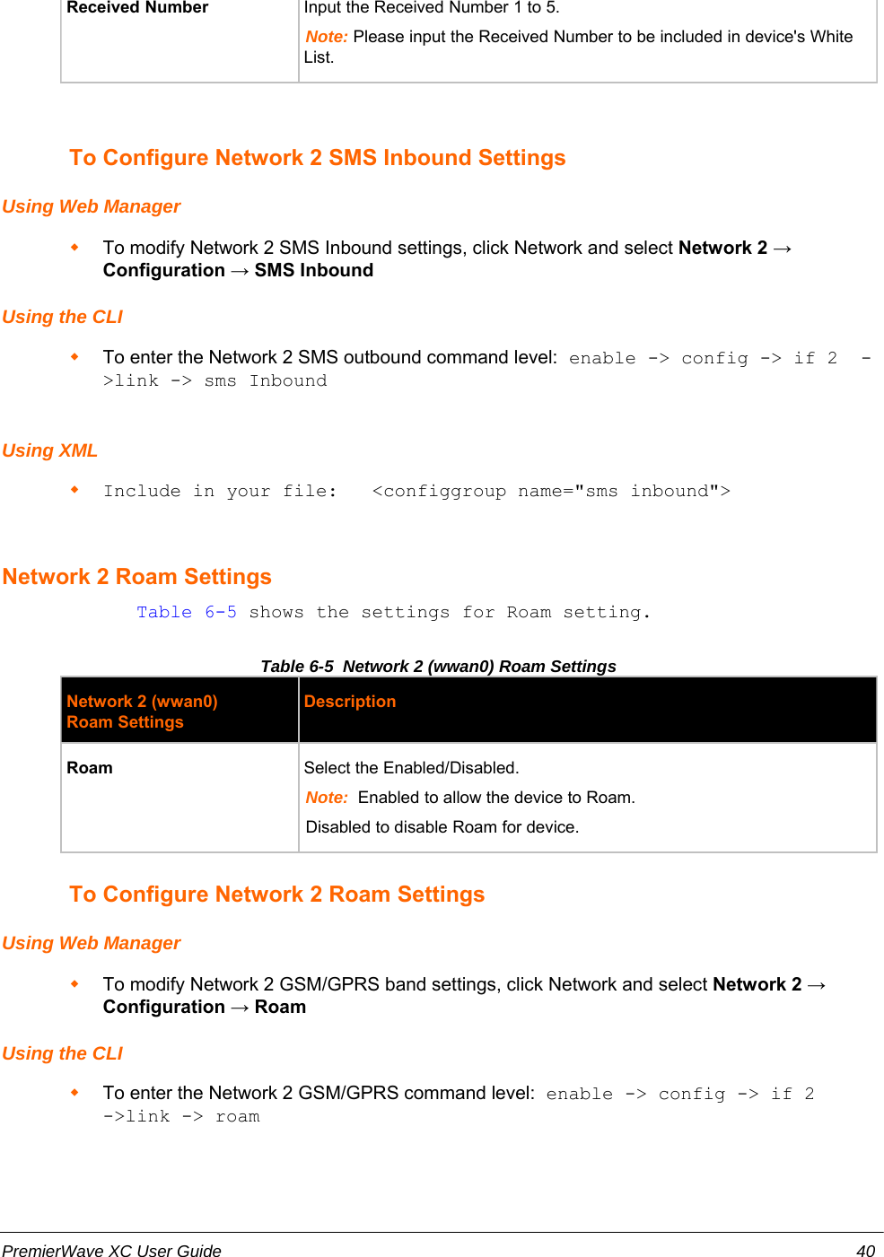
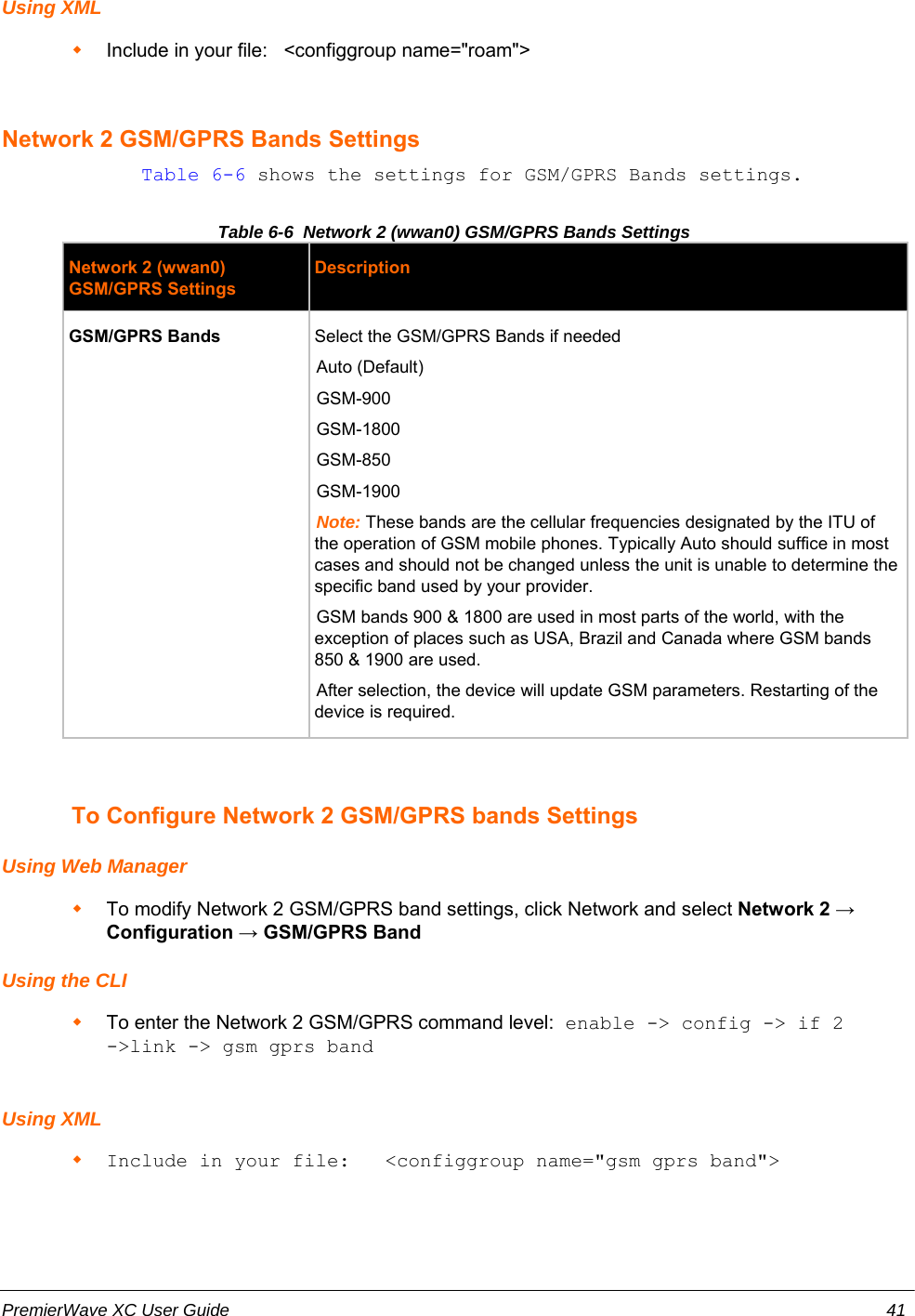
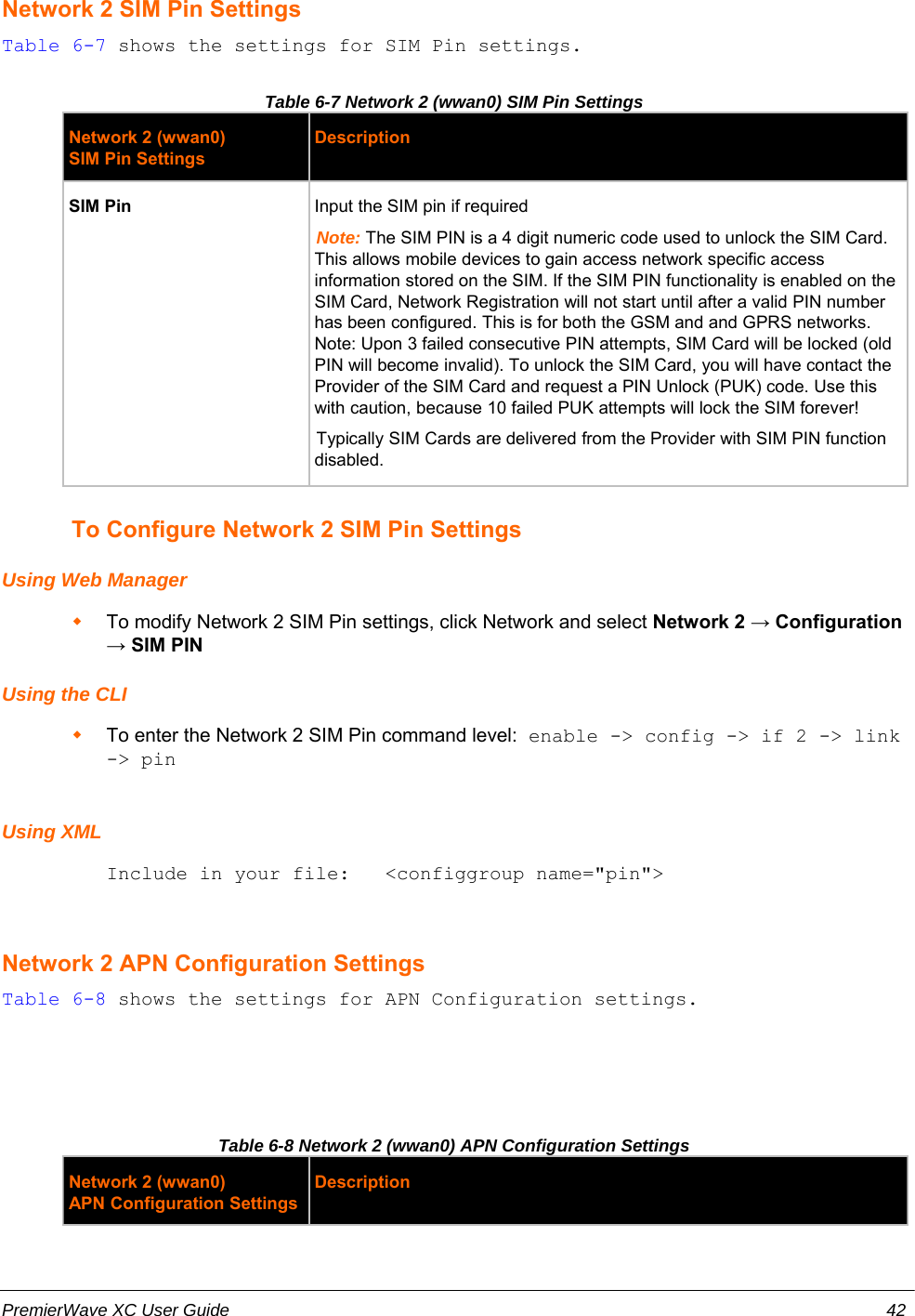
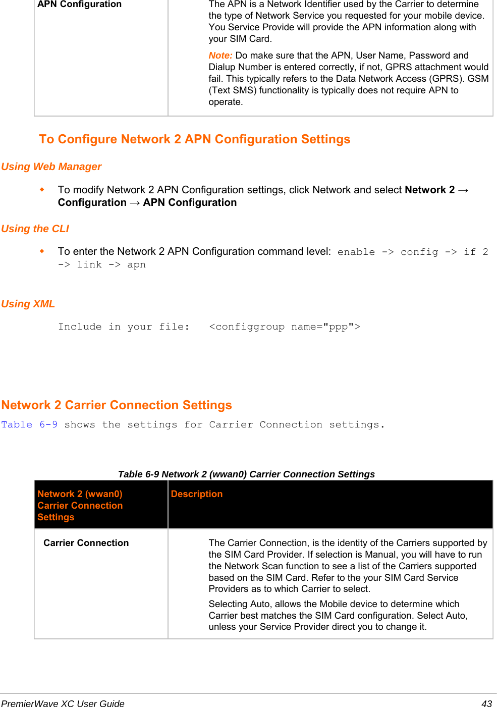
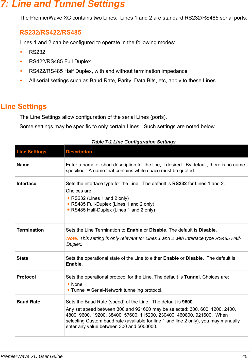
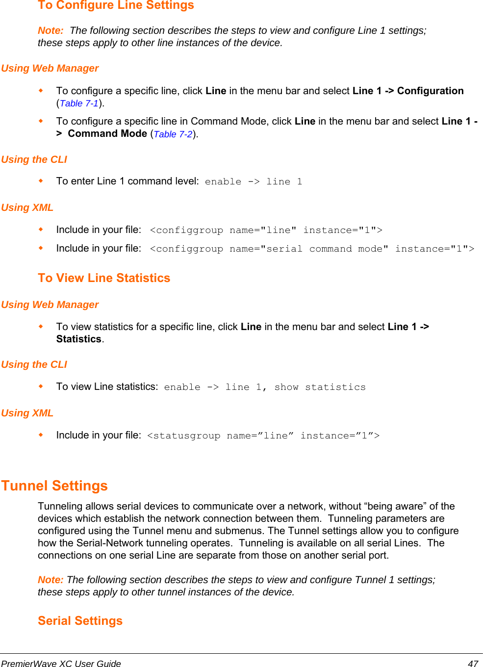
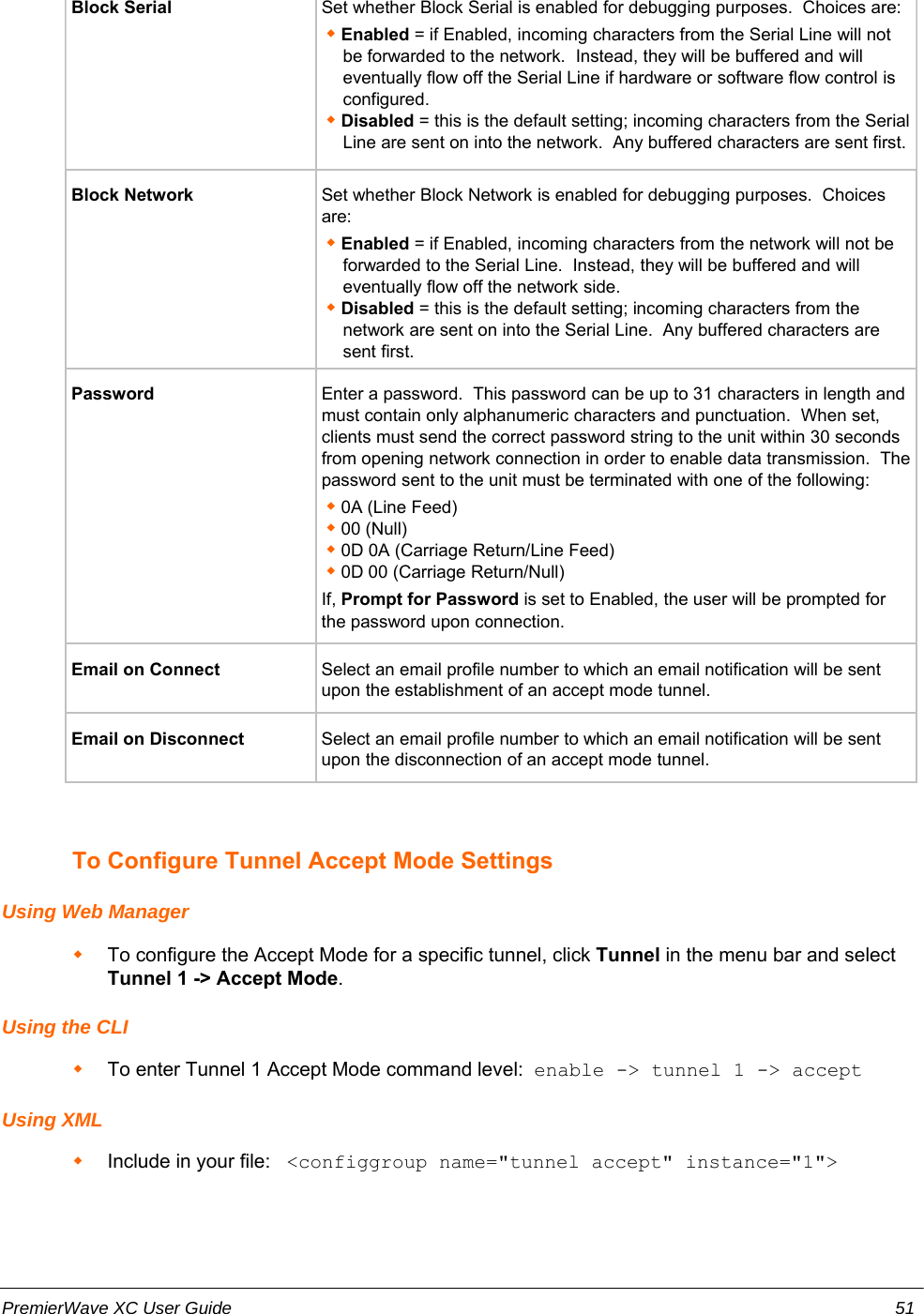
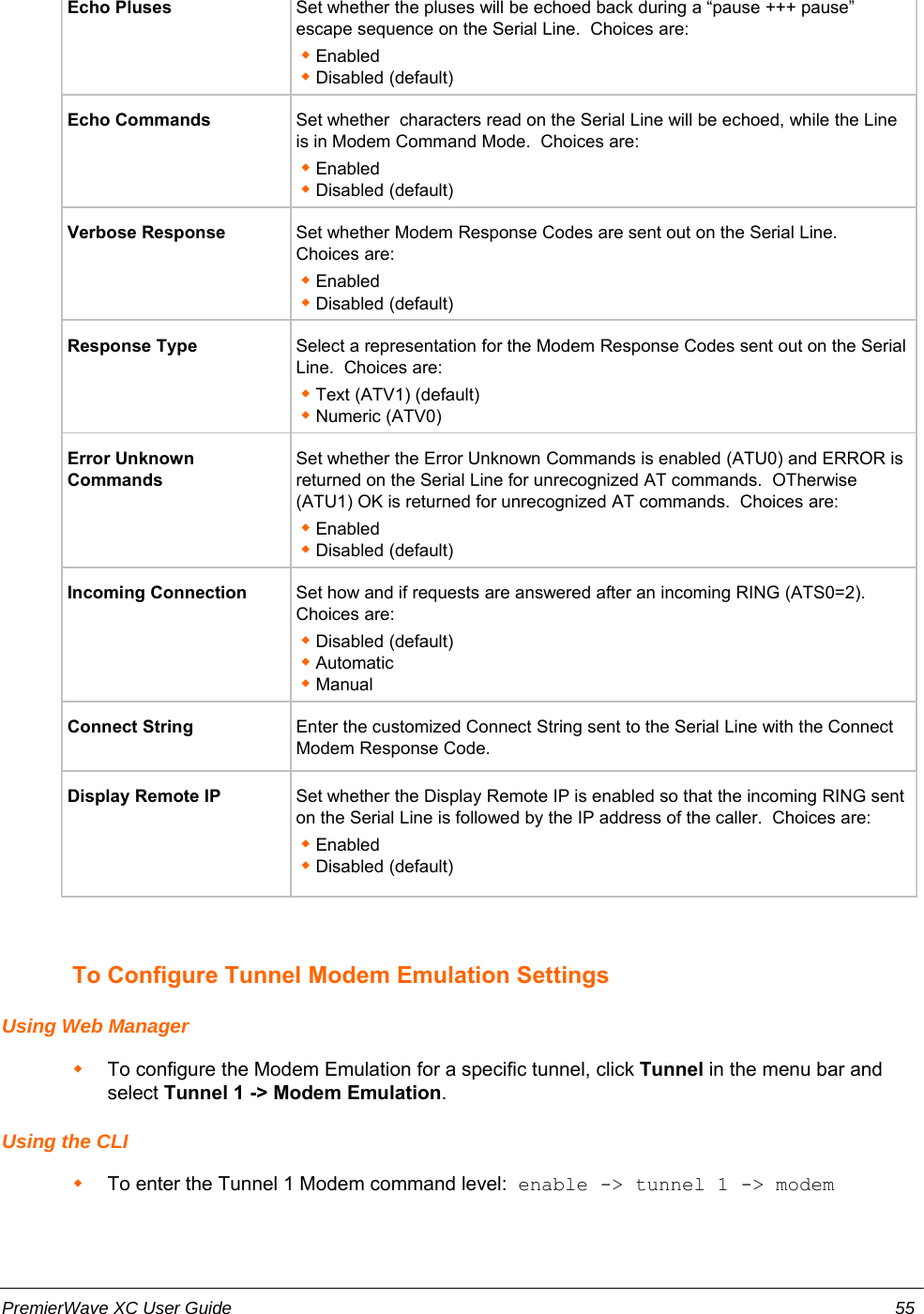
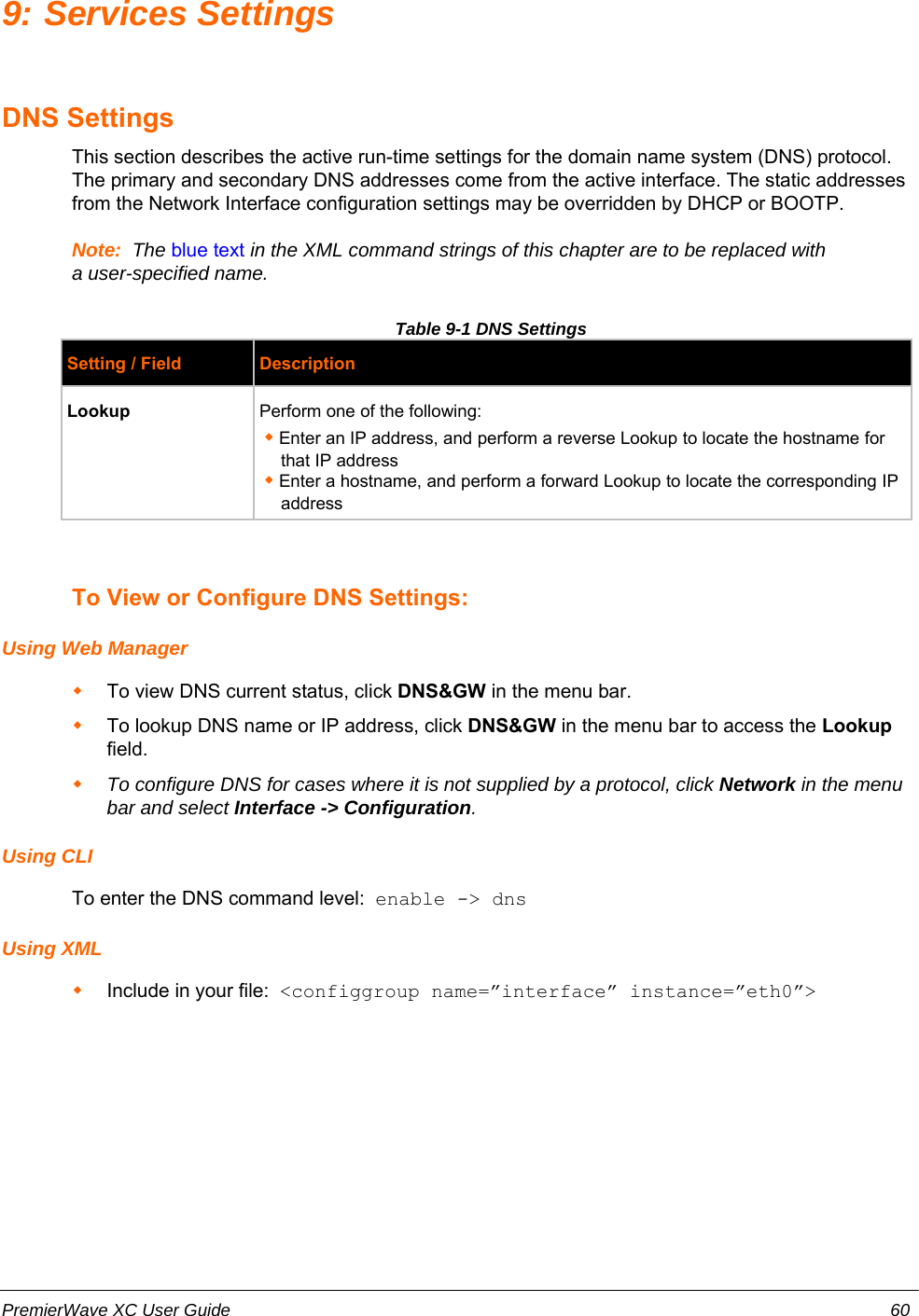
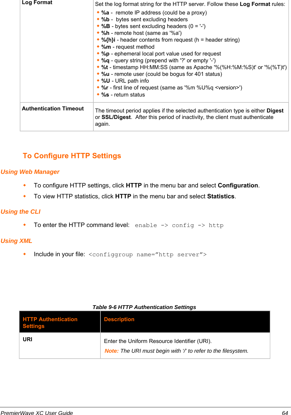
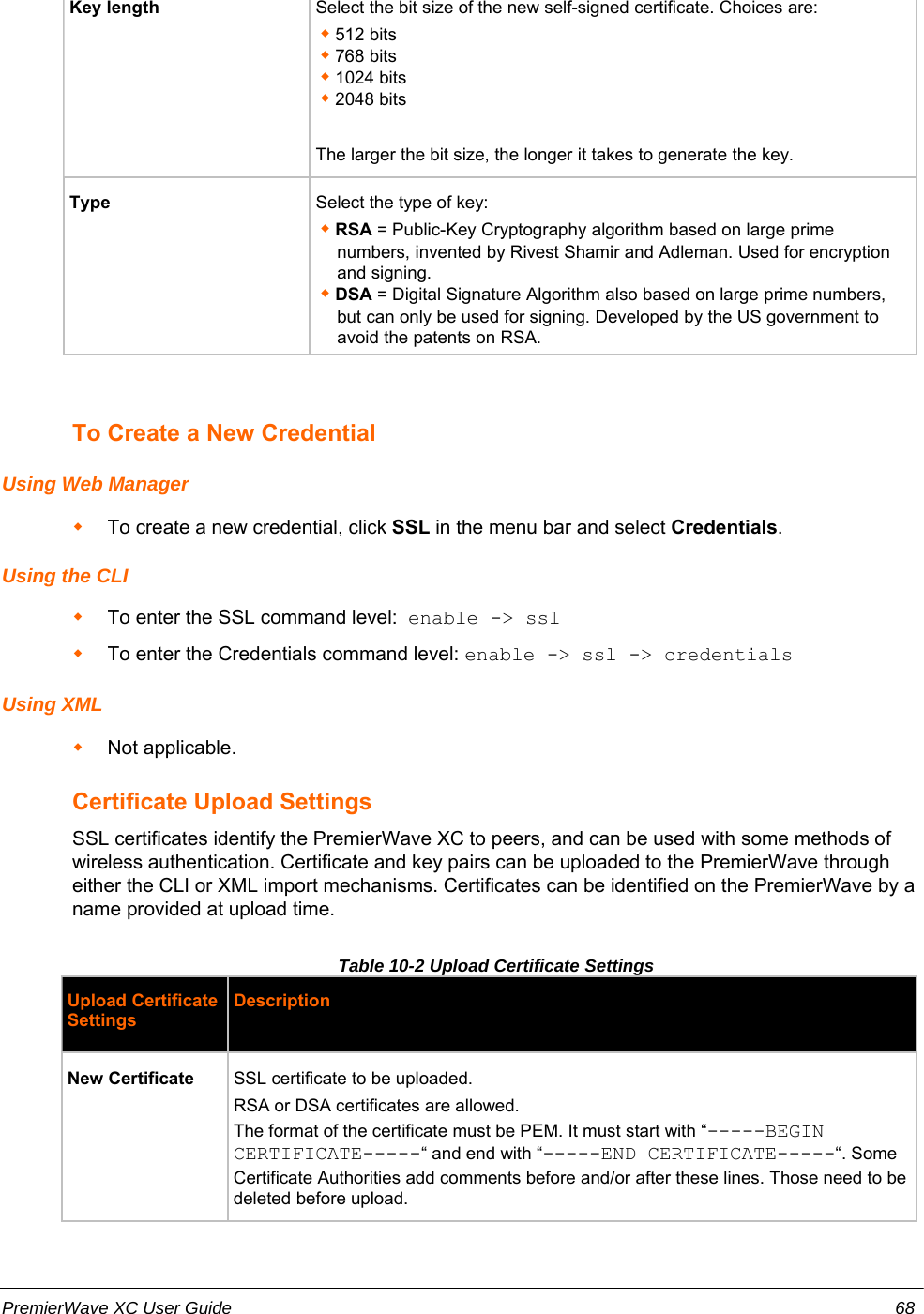
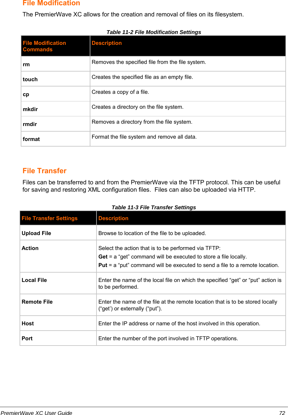
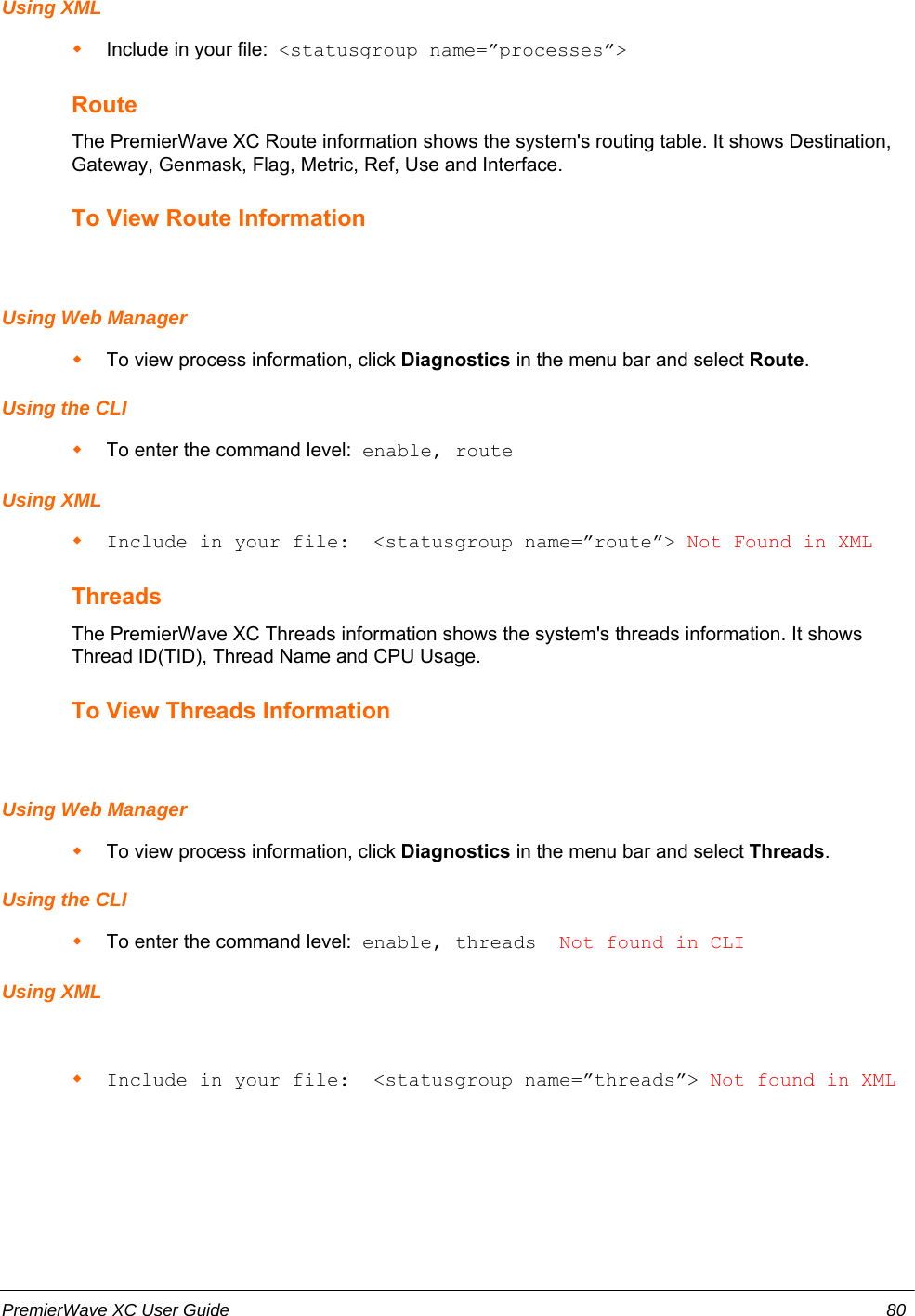
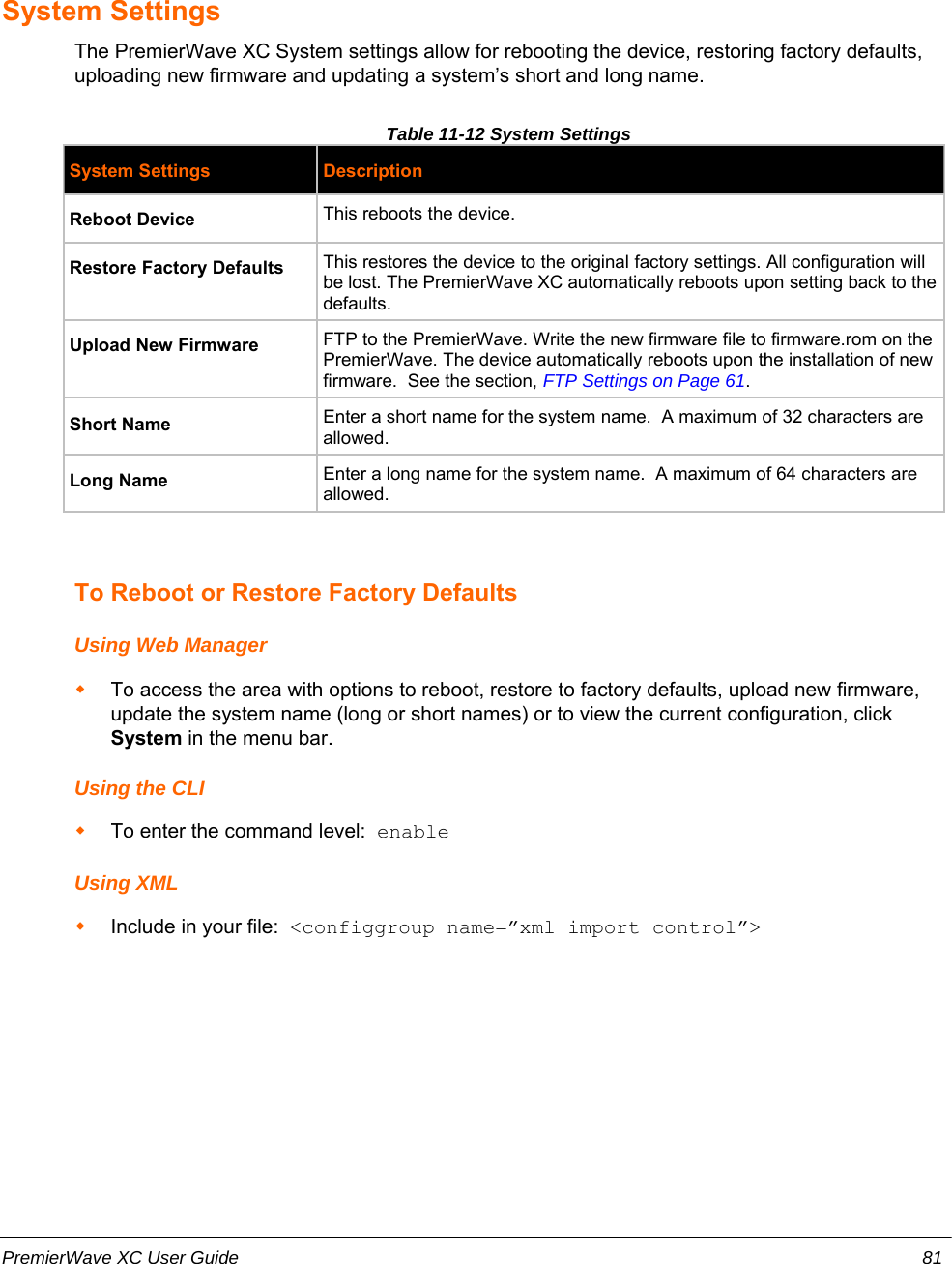
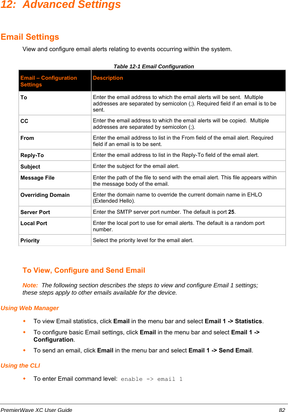
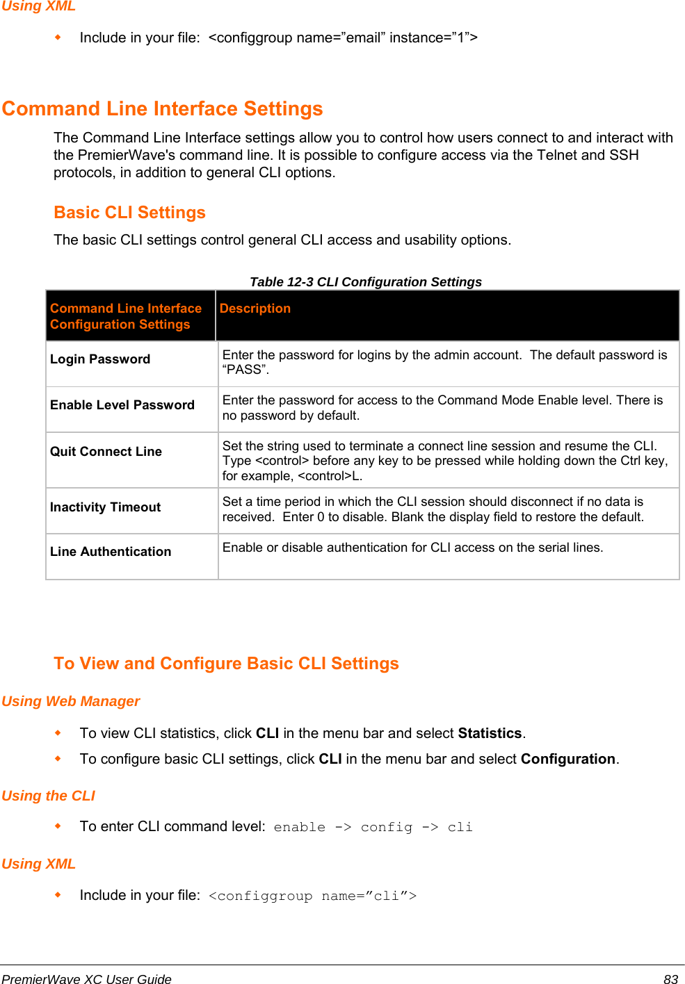
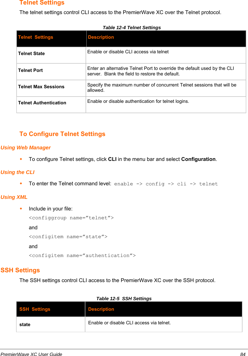
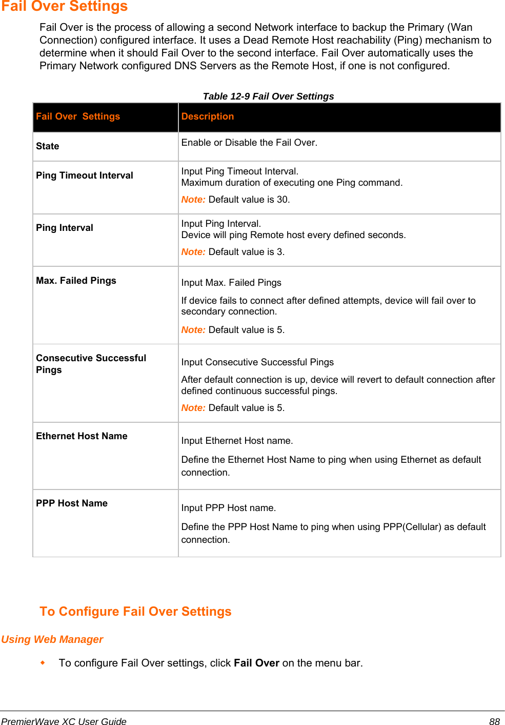
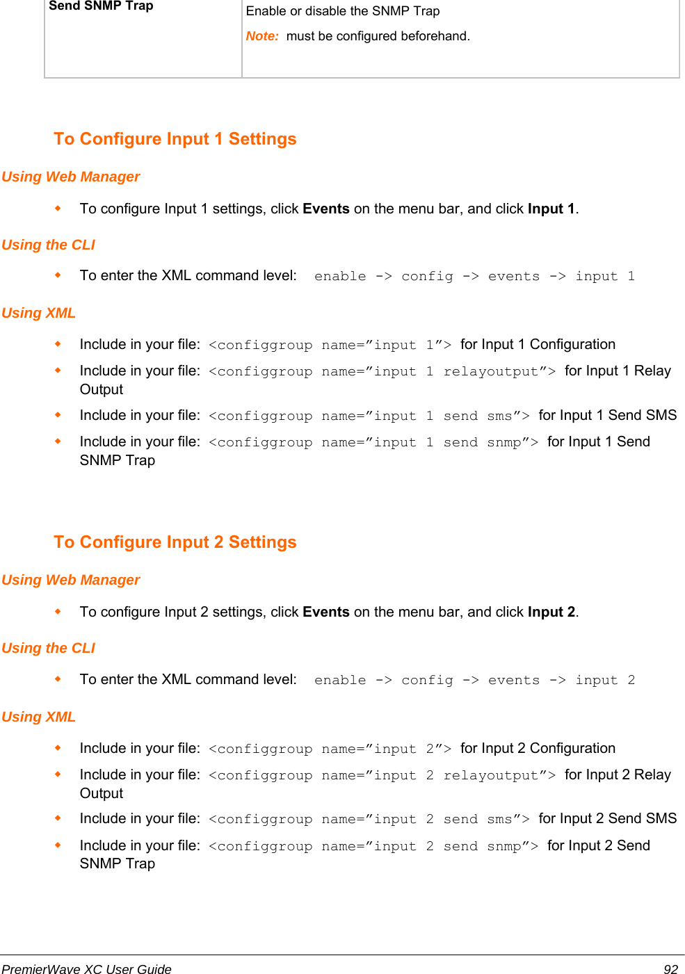
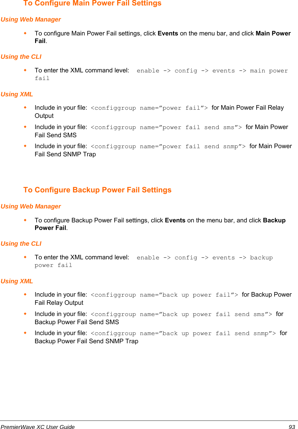
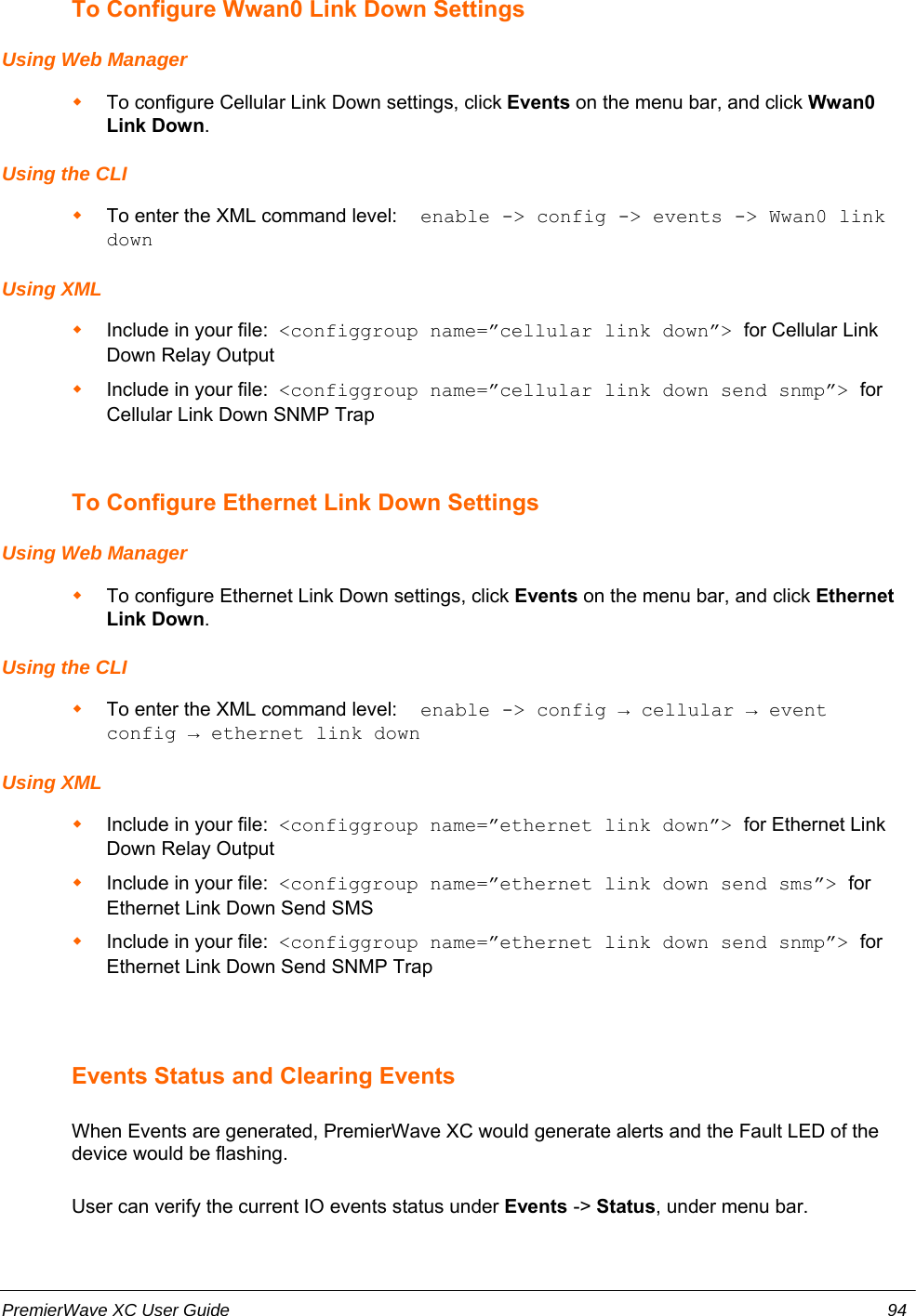
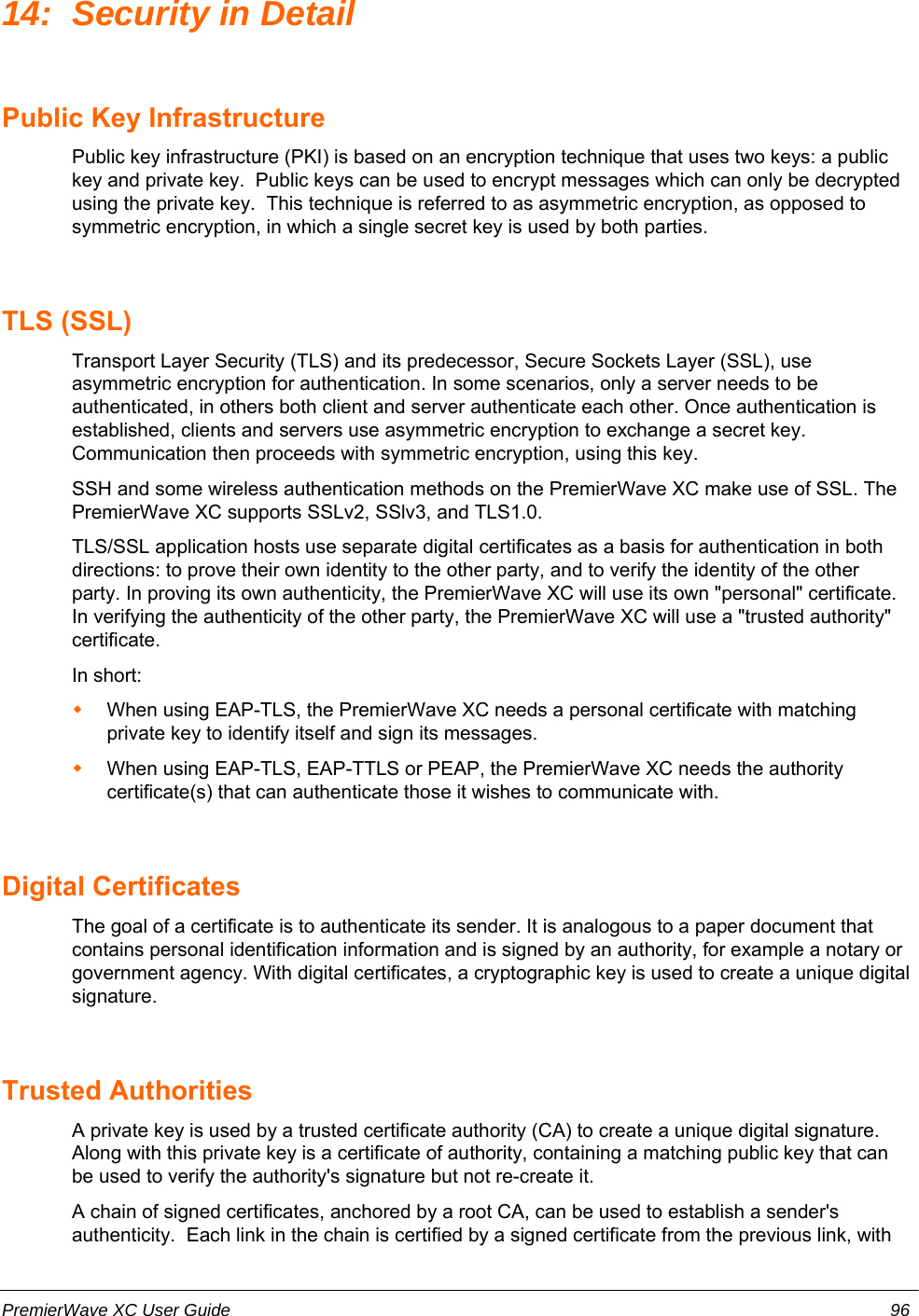
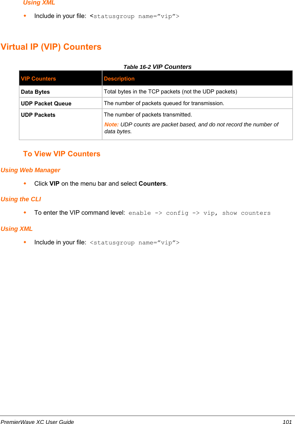
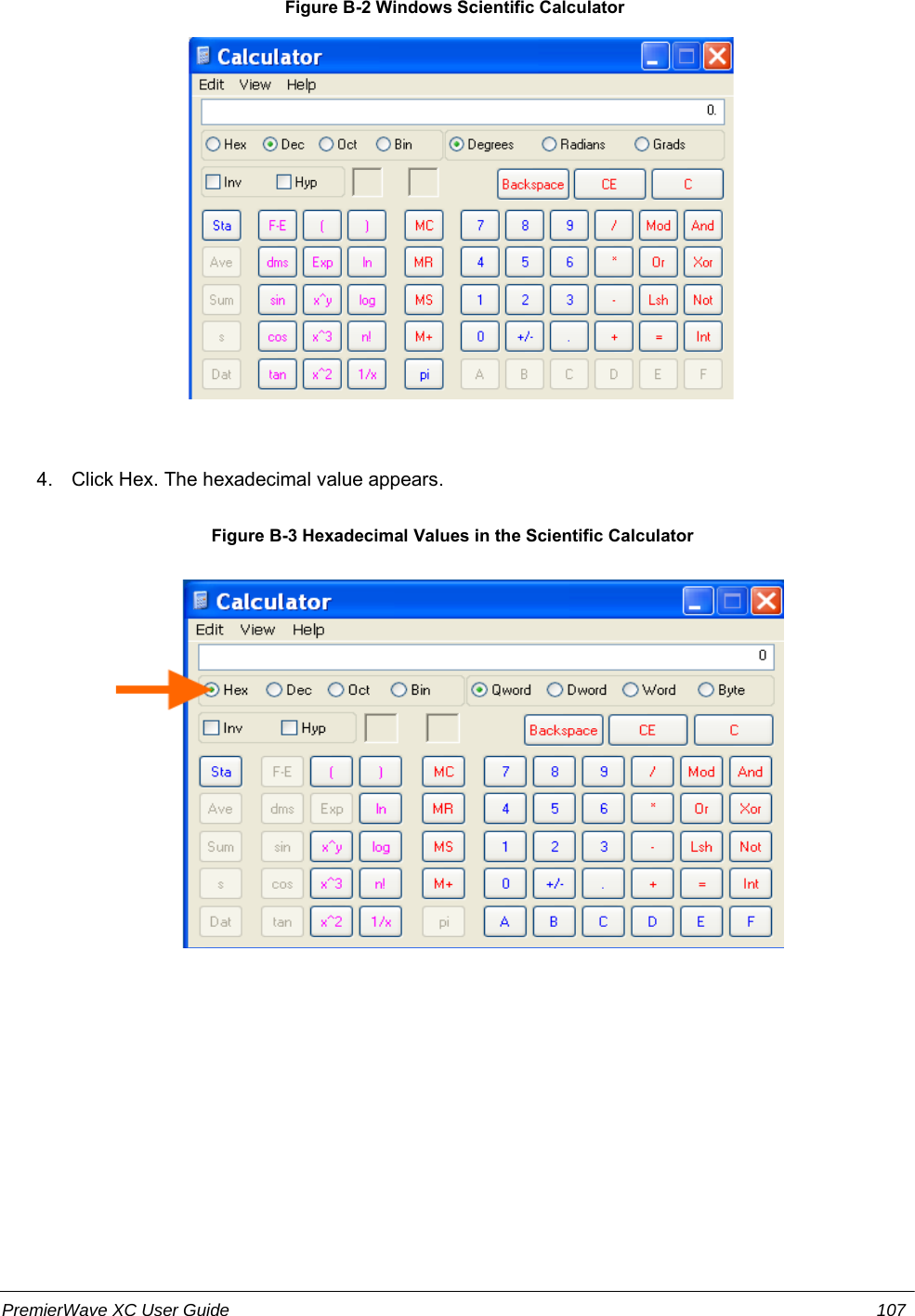
![Parity Sets the Parity of the Line. The default is None.Data Bits Sets the number of data bits for the Line. The default is 8.Stop Bits Sets the number of stop bits for the Line. The default is 1.Flow Control Sets the flow control for the Line. The default is None.Xon Char Set Xon Char to be used when Flow Control is set to Software. Prefix decimal with \or prefix hexadecimal with 0x or prefix a single control character <control>.Xoff Char Set Xoff Char to be used when Flow Control is set to Software. Prefix decimal with \or prefix hexadecimal with 0x or prefix a single control character <control>.Gap Timer Set the Gap Timer delay to Set the number of milliseconds to pass from the lastcharacter received before the driver forwards the received serial bytes. By default,the delay is four character periods at the current baud rate (minimum 1 ms).Threshold Set the number of threshold bytes which need to be received in order for the driver toforward received characters.Table 7-2 Line Command Mode SettingsLine CommandMode SettingsDescriptionMode Sets the Command Mode state of the Line. When in Command Mode, a CLI sessionoperates exclusively on the Line. Choices are:AlwaysUser Serial StringDisabledNote: In order to enable command mode on the Line, Tunneling on the Line must beDisabled (both connect and accept modes).Wait Time Enter the amount of time to wait during boot time for the Serial String. This timerstarts right after the Signon Message has been set on the Serial Line and applies onlyif mode is “Use Serial String”.Serial String Enter the Text or Binary string of bytes that must be read on the Serial Line duringboot time in order to enable Command Mode. It may contain a time element tospecify a required delay in milliseconds x, formed as {x}. Applies only if mode is“User Serial String”. It may contain a binary character(s) of the form [x]. Forexample, use decimal [12] or hex [0xc].Echo Serial String Select Yes or No for Echo Serial String. Applies only if mode is “User Serial String”.Select enable to echo received characters backed out on the line while looking for theserial string.Signon Message Enter the string of bytes to be sent to the Serial Line during boot time. It may containa binary character(s) of the form [x]. For example, use decimal [12] or hex [0xc].PremierWave XC User Guide 46](https://usermanual.wiki/lantronix/PWXC/User-Guide-1663321-Page-46.png)