lantronix WIBATT Wireless Device Server User Manual ethernet

lantronix Wireless Device Server ethernet

Contents

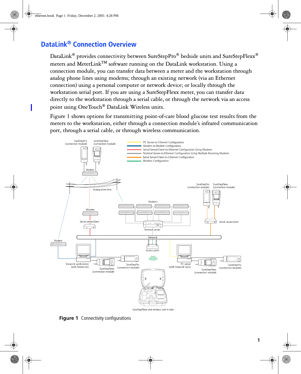
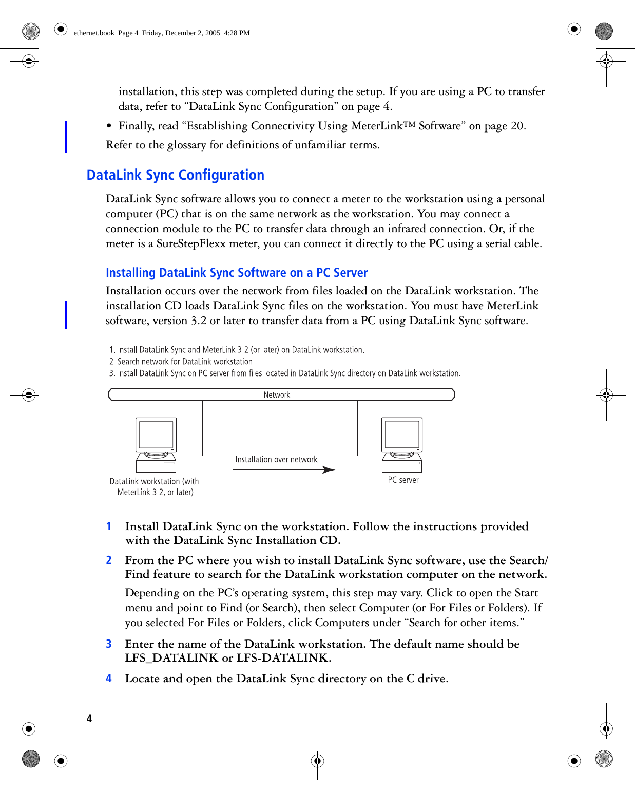
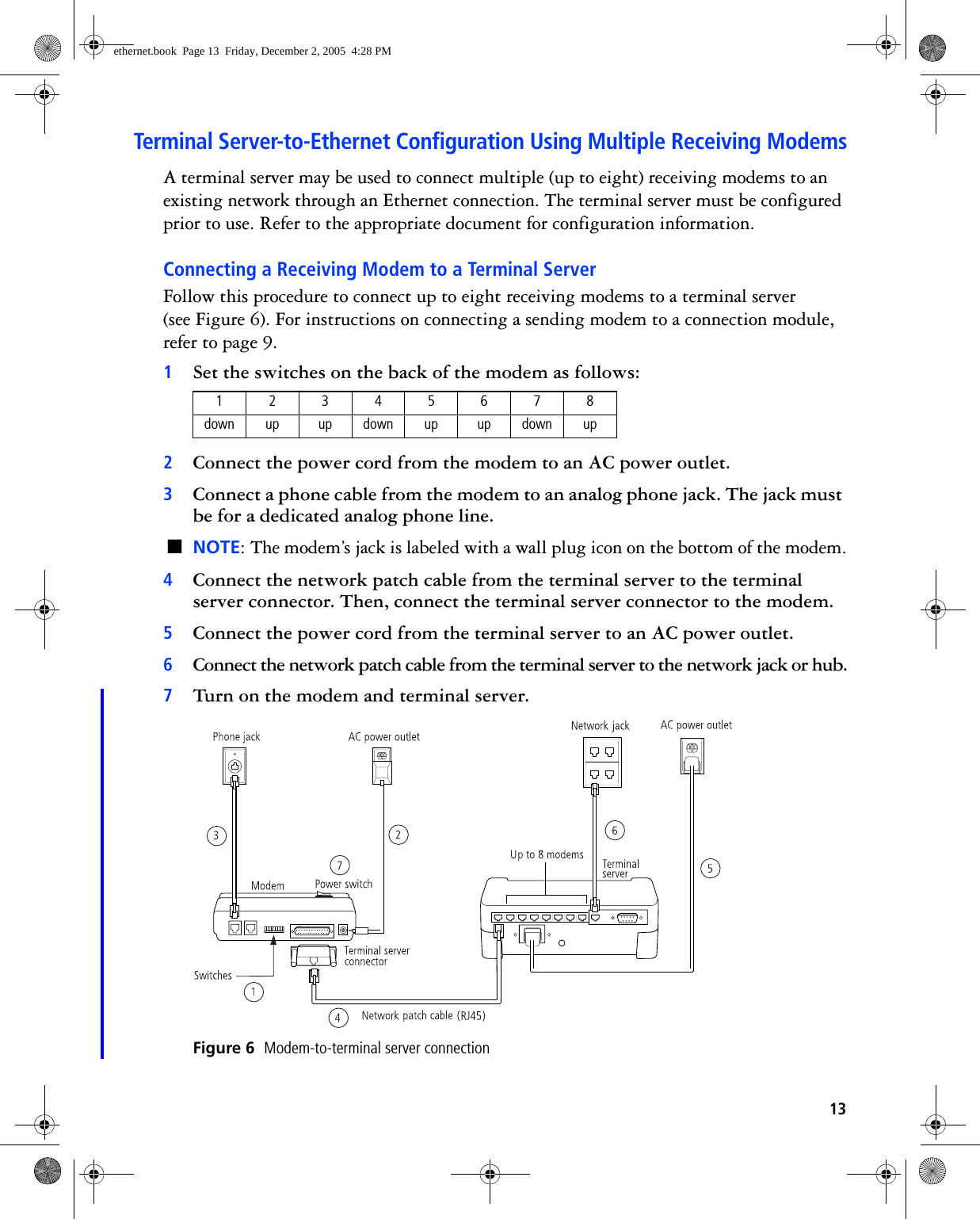
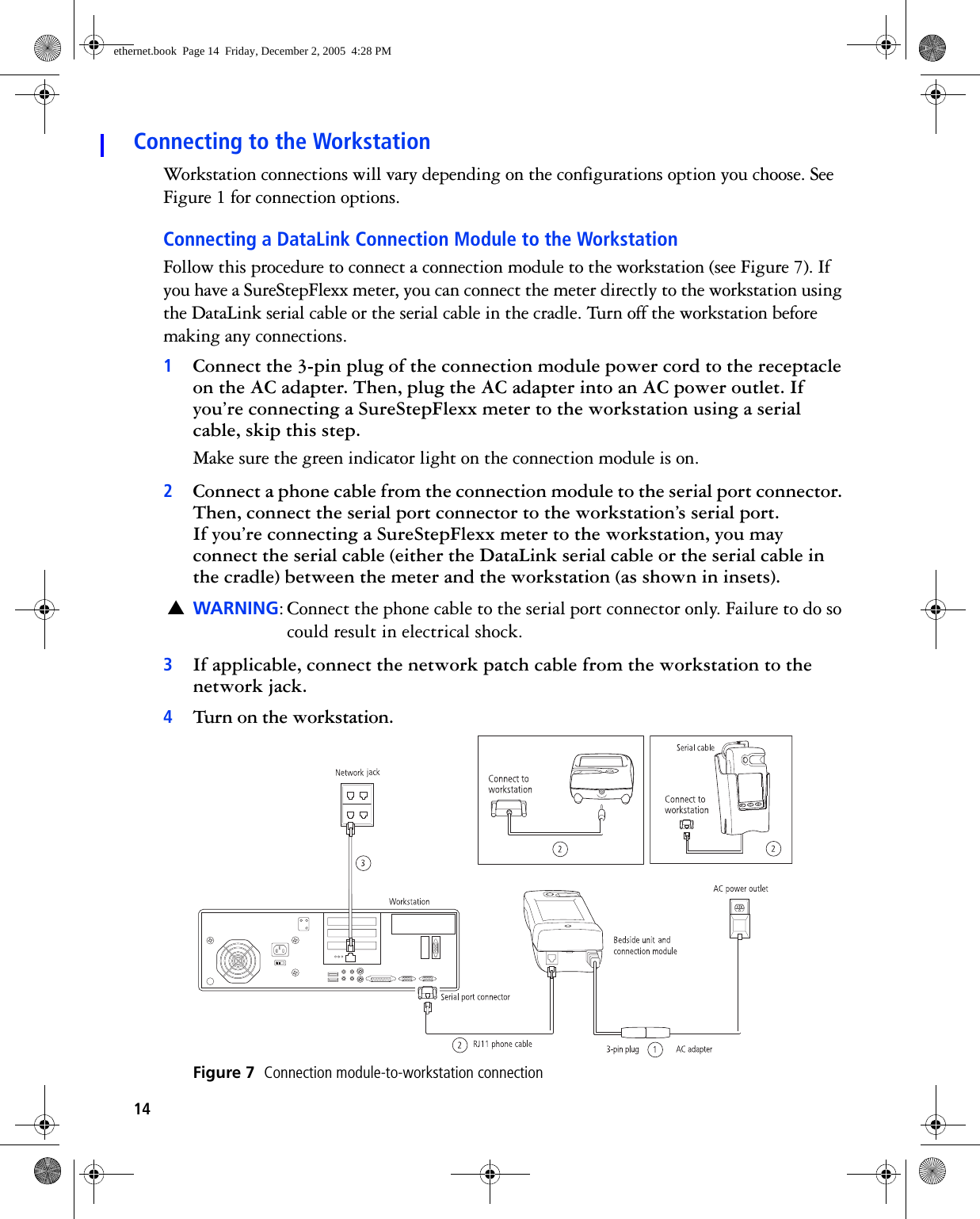
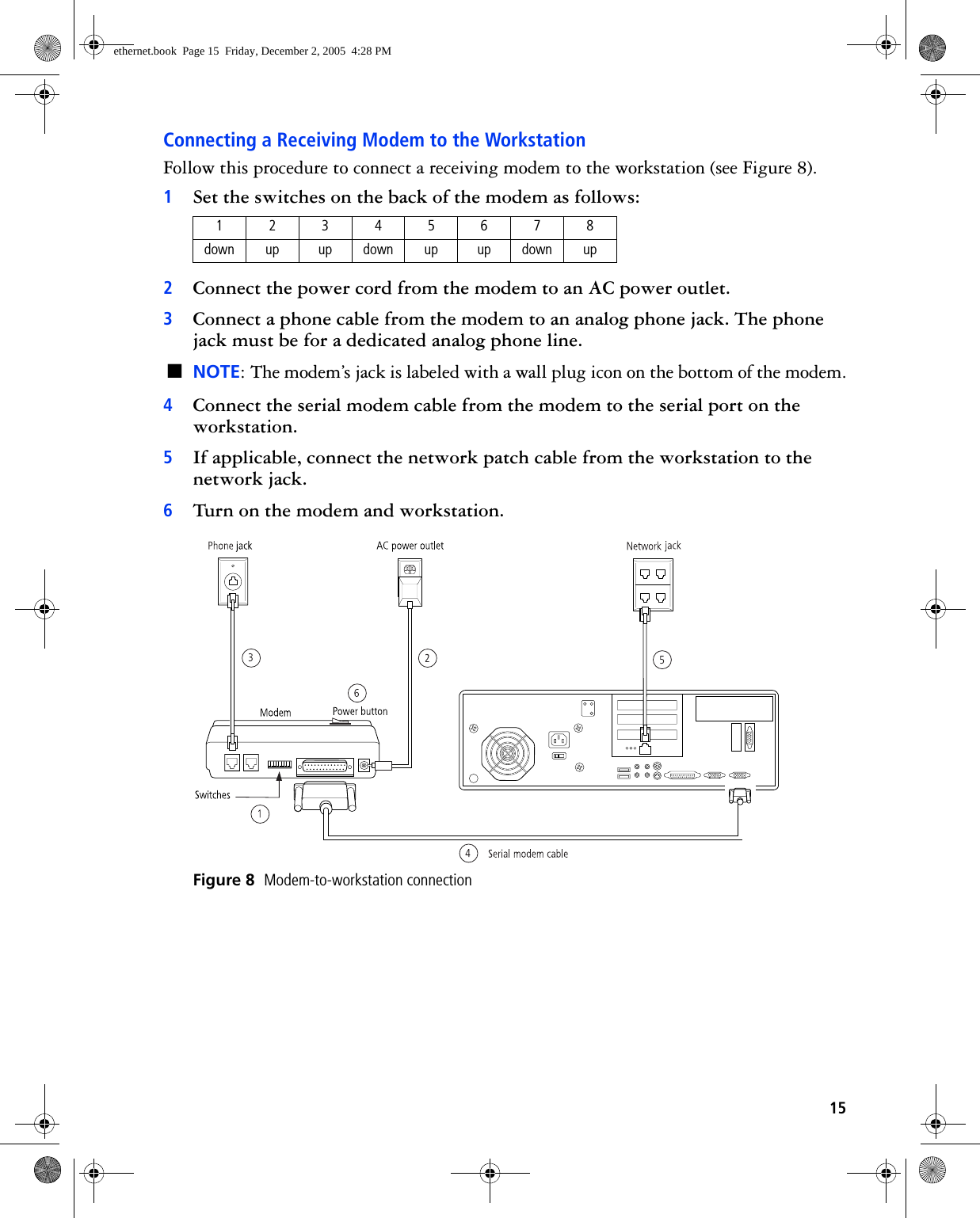
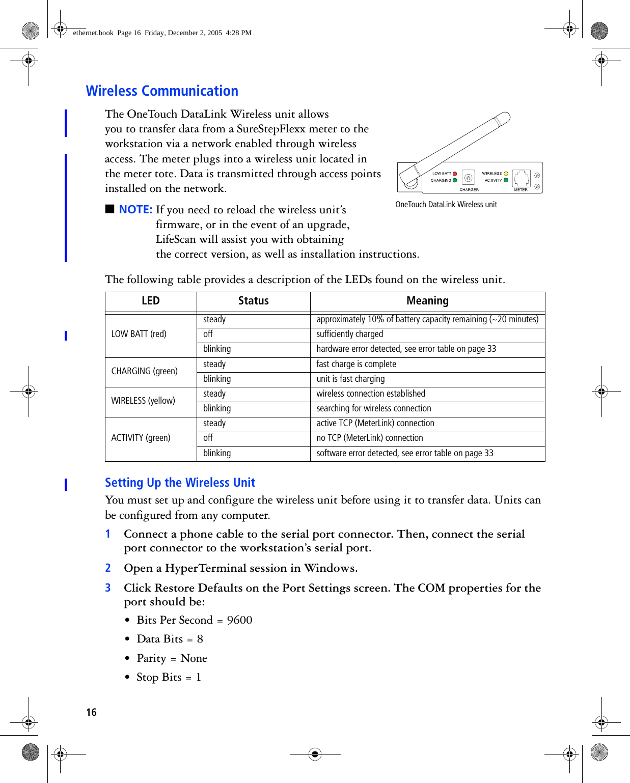
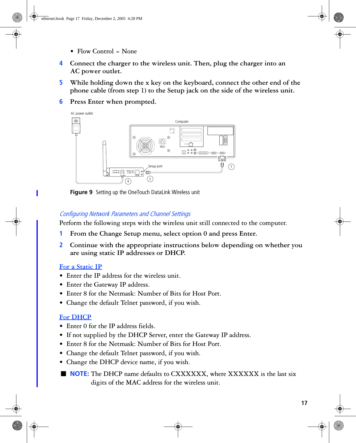
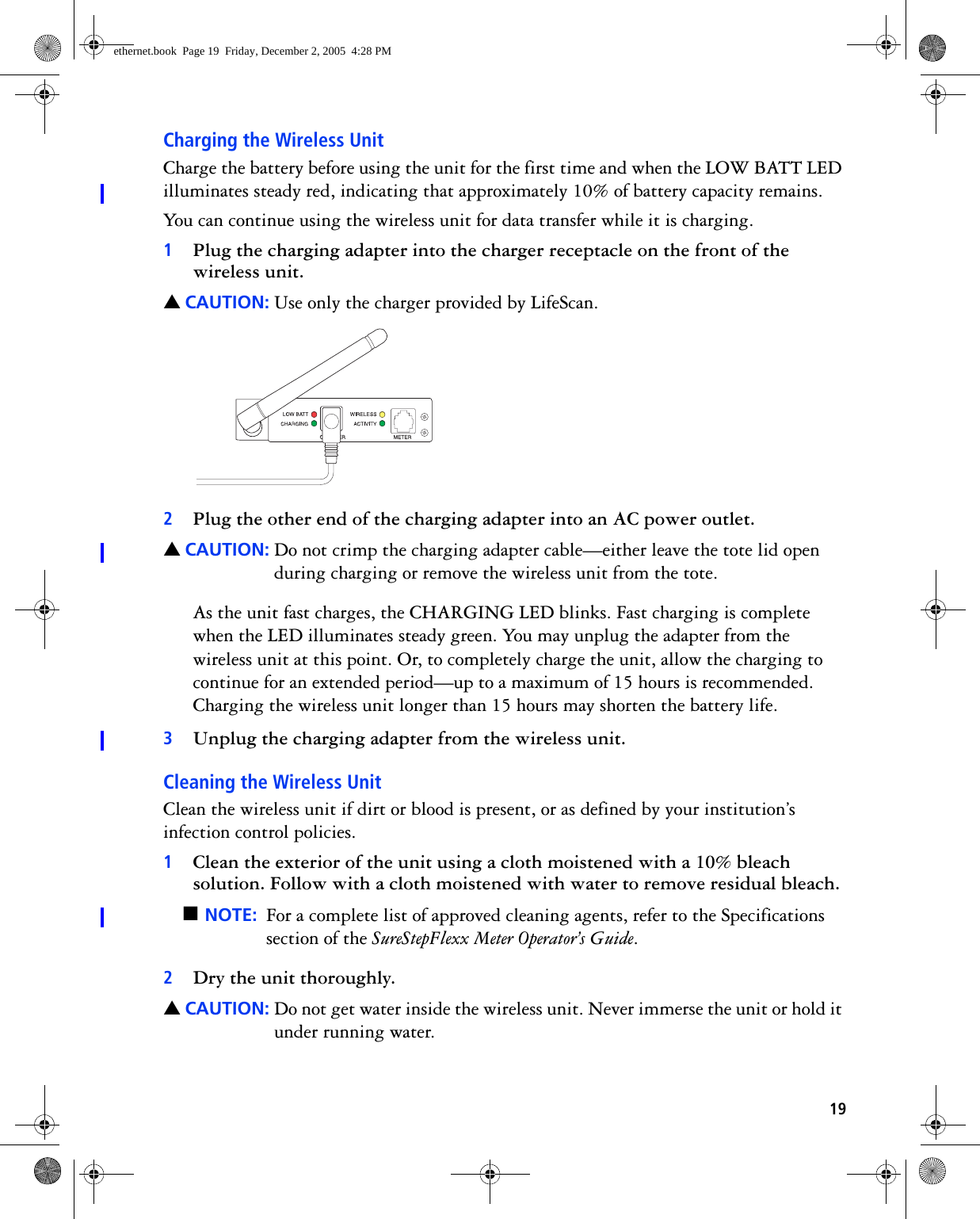
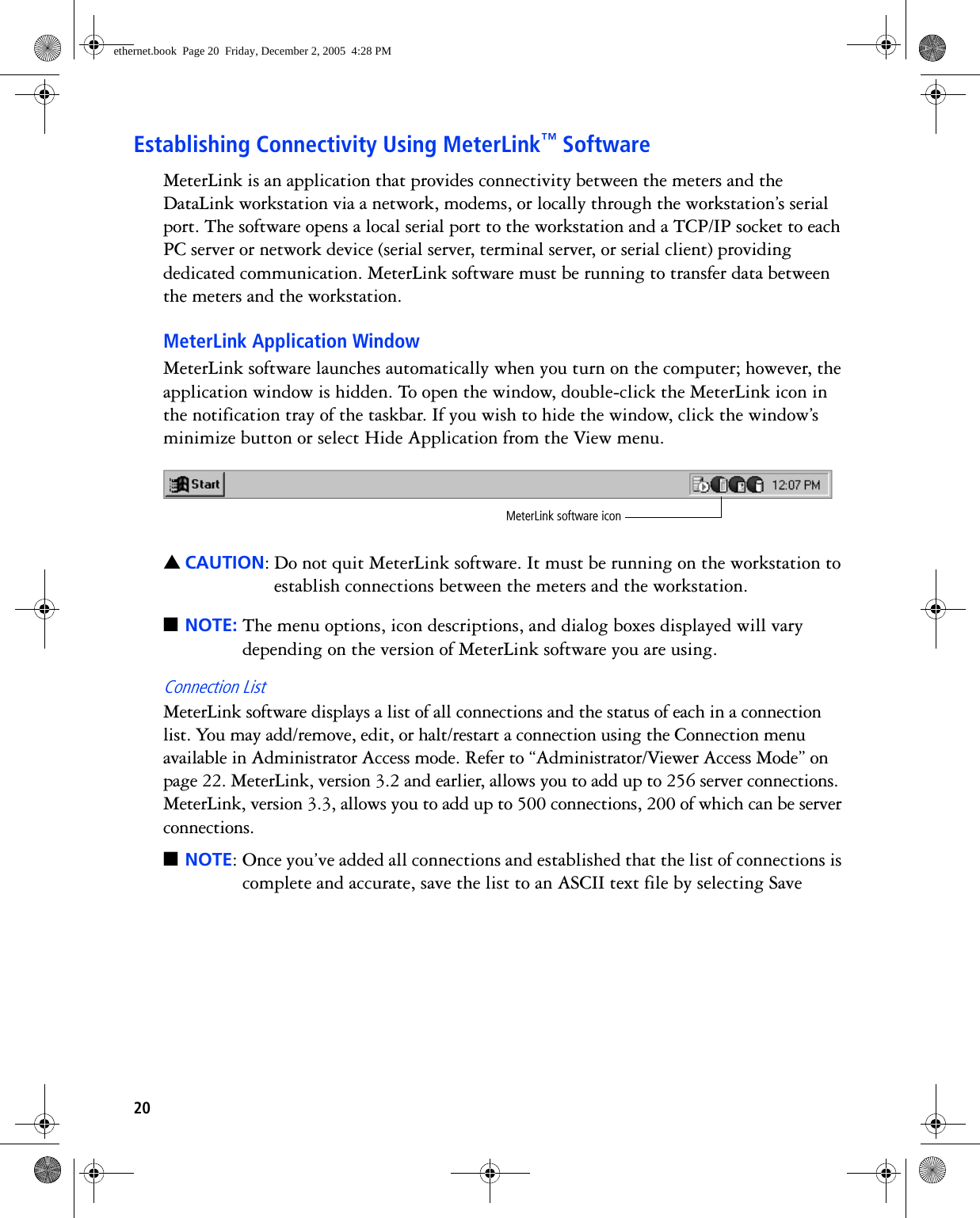
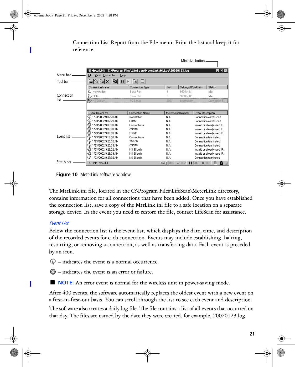
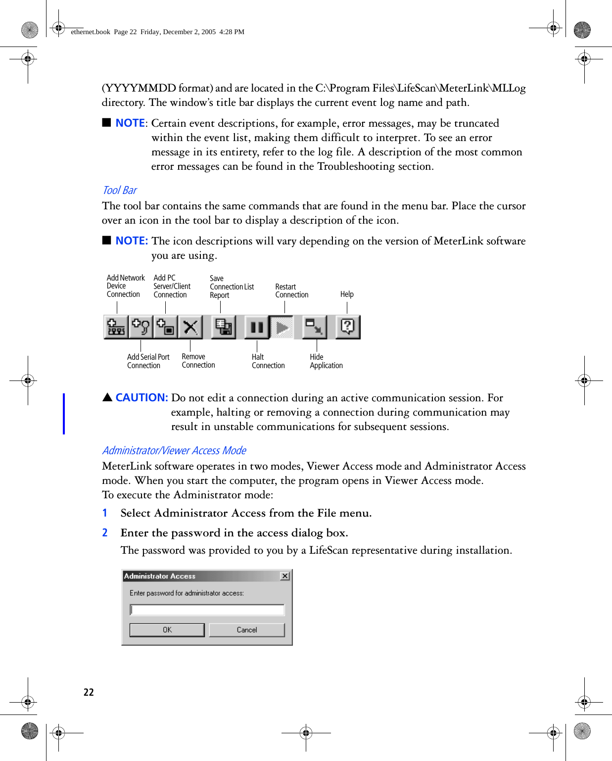
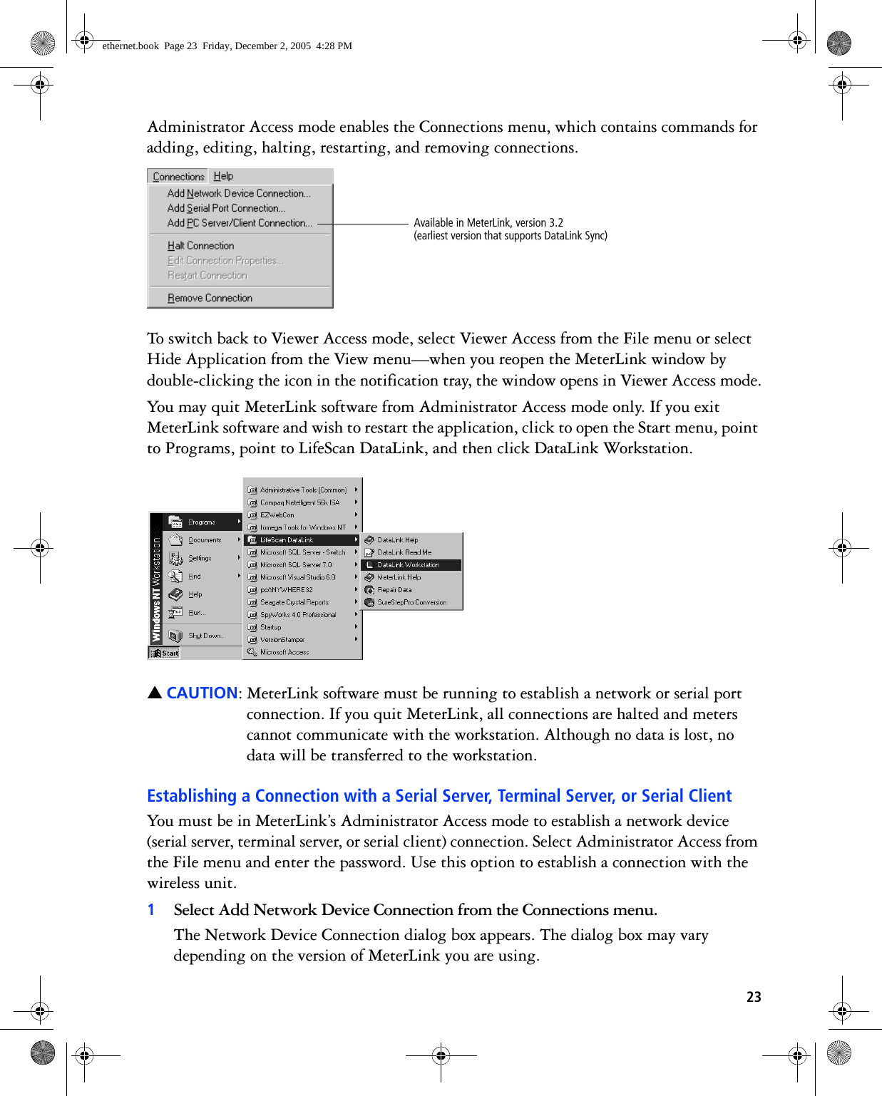
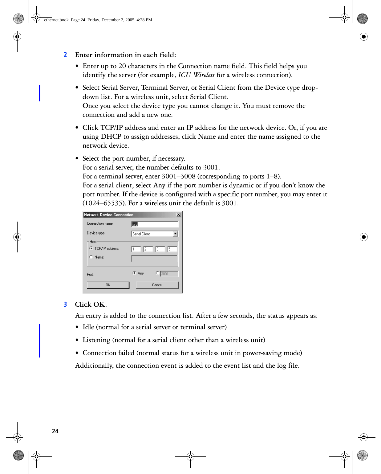
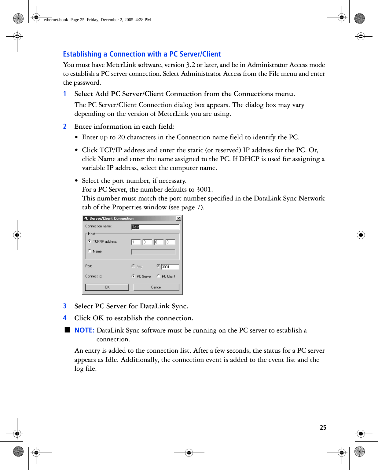
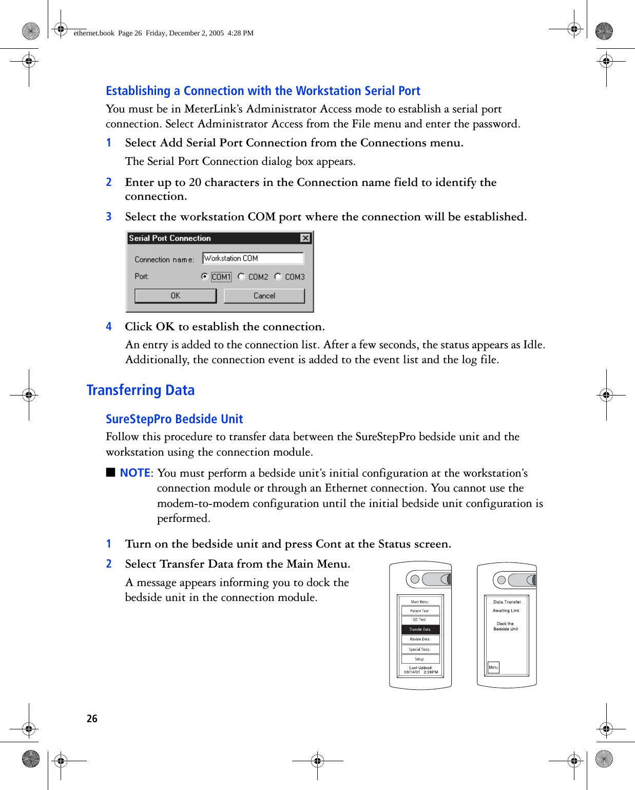
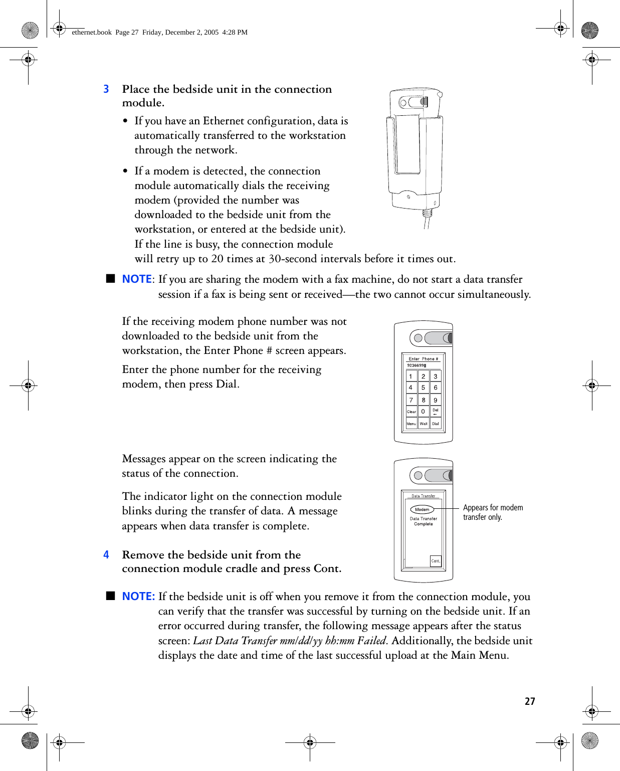
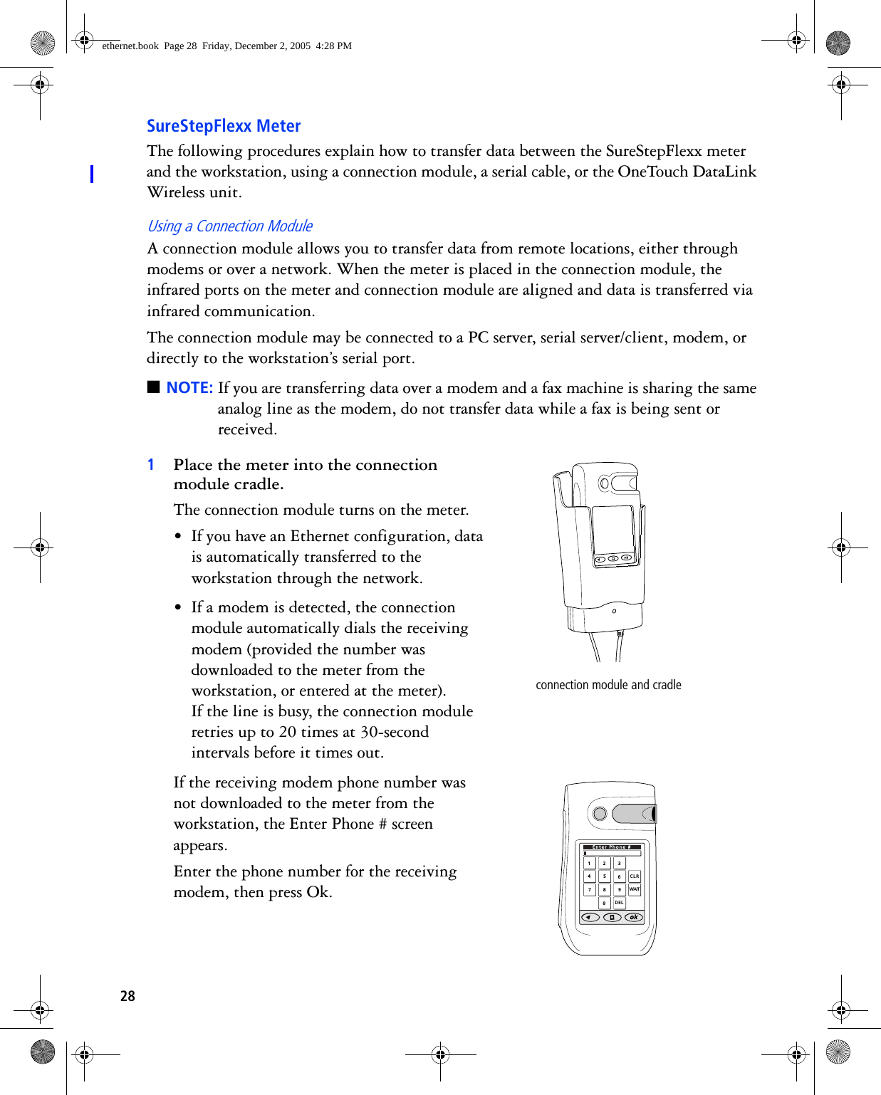
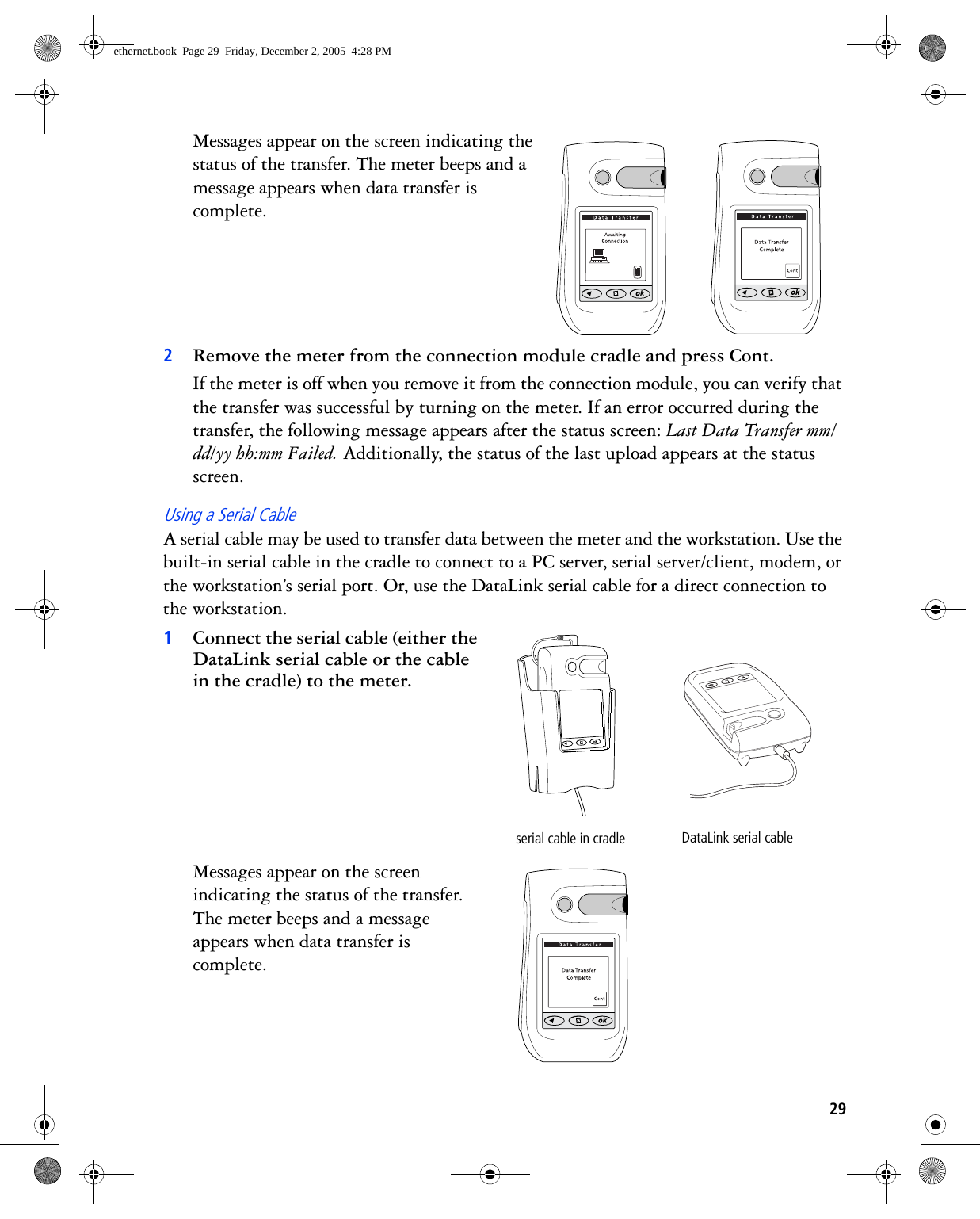
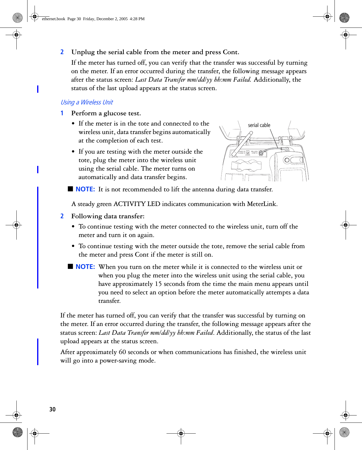
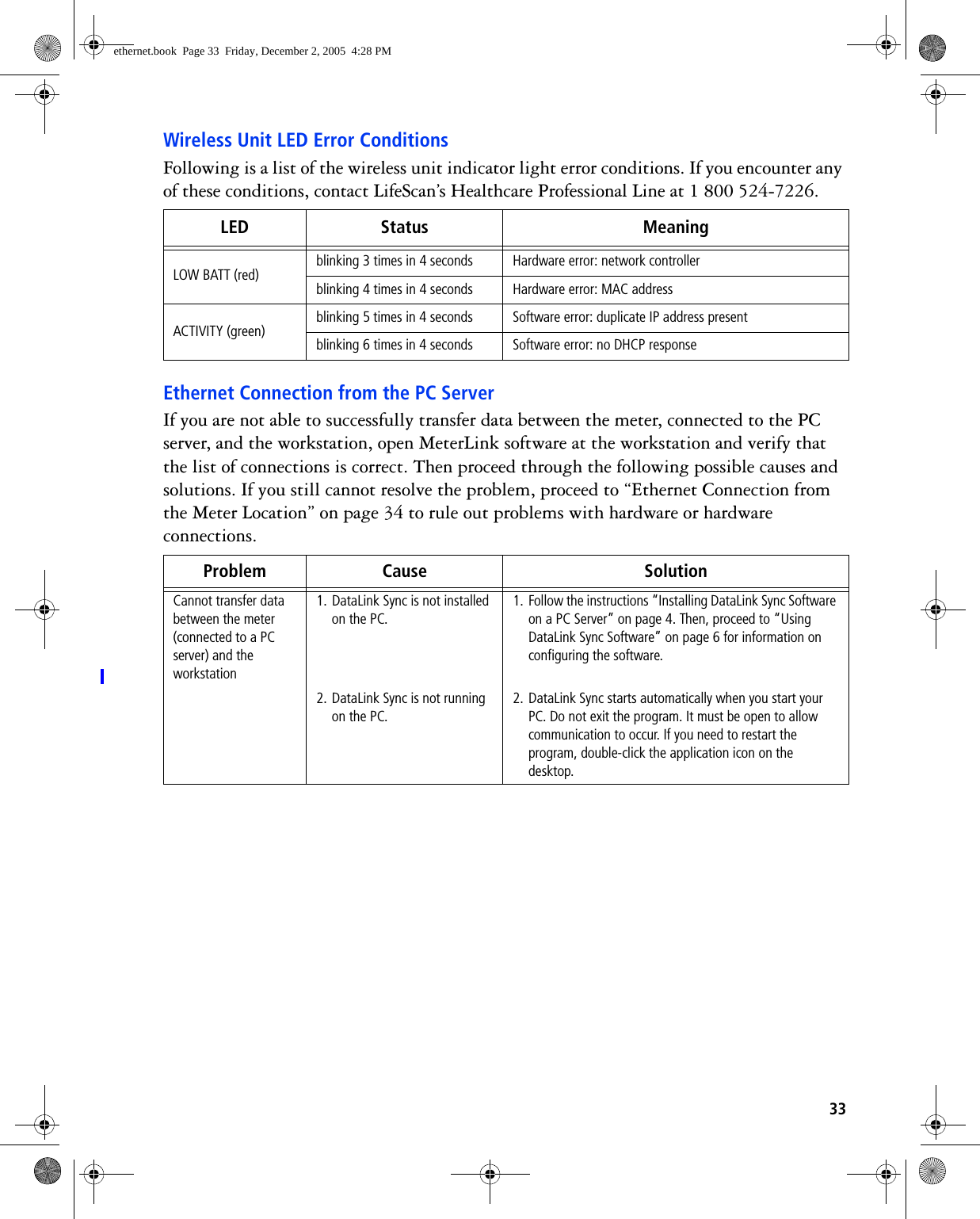
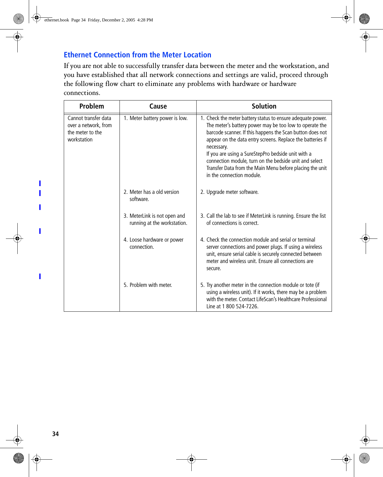
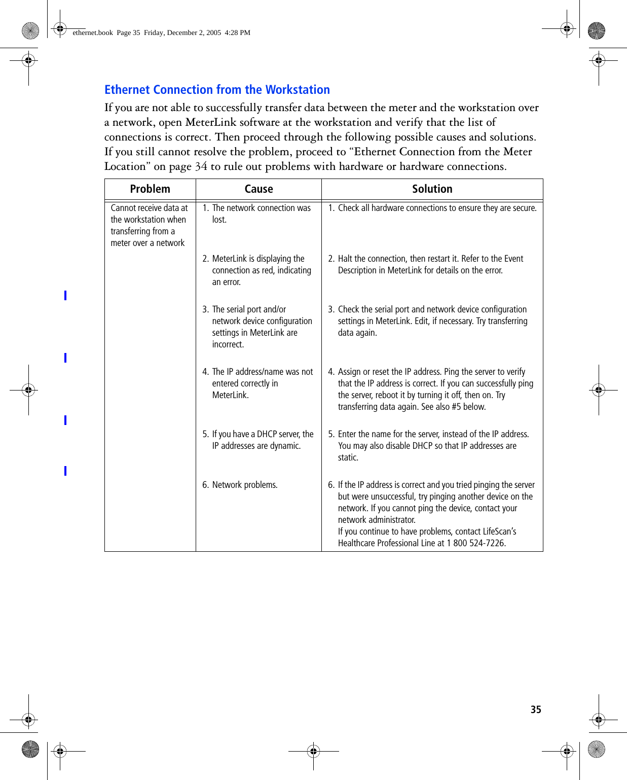
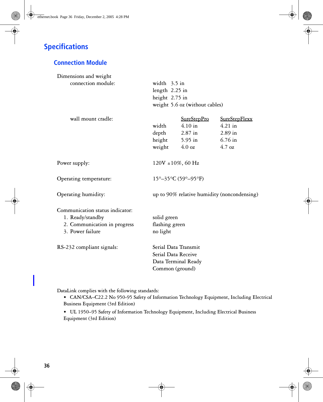
User Manual Data Link Connection

DataLink®Connection GuideDecember 2005ethernet.book  Page 1  Friday, December 2, 2005  4:28 PM
Copyright © 2005 LifeScan, Inc. All rights reserved. No part of this publication may be reproduced, transmitted, transcribed, stored in retrieval systems, or translated into any language or computer language, in any form, or by any means: electronic, mechanical, magnetic, optical, or otherwise, without the prior written permission of LifeScan, Inc, 1000 Gibraltar Drive, Milpitas, California, 95035, United States of America.Disclaimer LifeScan reserves the right to change its products and services at any time to incorporate the latest technological developments. This guide is subject to change without notice.Trademarks OneTouch, DataLink, SureStepFlexx, and SureStepPro are registered trademarks of LifeScan, Inc.MeterLink is a trademark of LifeScan, Inc.Lantronix is a registered trademark of Lantronix. Windows is a registered trademark of Microsoft Corporation.InstallAnywhere is a registered trademark of Zero G Software, Inc.ethernet.book  Page 2  Friday, December 2, 2005  4:28 PM
iDataLink® Connection Overview  . . . . . . . . . . . . . . . . . . . . . . . . . . . . . . . . . . . . . . . . . . . .  1Direct Connection  . . . . . . . . . . . . . . . . . . . . . . . . . . . . . . . . . . . . . . . . . . . . . . . . . . . . .  2Modem Configuration  . . . . . . . . . . . . . . . . . . . . . . . . . . . . . . . . . . . . . . . . . . . . . . . . . .  2Network Configuration  . . . . . . . . . . . . . . . . . . . . . . . . . . . . . . . . . . . . . . . . . . . . . . . . .  2Using This Guide   . . . . . . . . . . . . . . . . . . . . . . . . . . . . . . . . . . . . . . . . . . . . . . . . . . . . .  3DataLink Sync Configuration  . . . . . . . . . . . . . . . . . . . . . . . . . . . . . . . . . . . . . . . . . . . . . . .  4Installing DataLink Sync Software on a PC Server   . . . . . . . . . . . . . . . . . . . . . . . . . . . . .  4Connecting a DataLink Connection Module to the PC Server . . . . . . . . . . . . . . . . . . . . .  6Using DataLink Sync Software  . . . . . . . . . . . . . . . . . . . . . . . . . . . . . . . . . . . . . . . . . . . .  6Modem-to-Modem Configuration . . . . . . . . . . . . . . . . . . . . . . . . . . . . . . . . . . . . . . . . . . . .  9Connecting a DataLink Connection Module to a Sending Modem   . . . . . . . . . . . . . . . . .  9Serial Server/Client-to-Ethernet Configuration  . . . . . . . . . . . . . . . . . . . . . . . . . . . . . . . . .  10Connecting a DataLink Connection Module to a Serial Server/Client  . . . . . . . . . . . . . .  10Serial Server/Client-to-Ethernet Configuration Using Modems . . . . . . . . . . . . . . . . . . . . .  11Connecting a Receiving Modem to a Serial Server/Client  . . . . . . . . . . . . . . . . . . . . . . .  12Terminal Server-to-Ethernet Configuration Using Multiple Receiving Modems . . . . . . . .  13Connecting a Receiving Modem to a Terminal Server   . . . . . . . . . . . . . . . . . . . . . . . . .  13Connecting to the Workstation   . . . . . . . . . . . . . . . . . . . . . . . . . . . . . . . . . . . . . . . . . . . .  14Connecting a DataLink Connection Module to the Workstation   . . . . . . . . . . . . . . . . .  14Connecting a Receiving Modem to the Workstation   . . . . . . . . . . . . . . . . . . . . . . . . . .  15Wireless Communication  . . . . . . . . . . . . . . . . . . . . . . . . . . . . . . . . . . . . . . . . . . . . . . . . .  16Setting Up the Wireless Unit   . . . . . . . . . . . . . . . . . . . . . . . . . . . . . . . . . . . . . . . . . . .  16Charging the Wireless Unit  . . . . . . . . . . . . . . . . . . . . . . . . . . . . . . . . . . . . . . . . . . . . .  19Cleaning the Wireless Unit  . . . . . . . . . . . . . . . . . . . . . . . . . . . . . . . . . . . . . . . . . . . . .  19Establishing Connectivity Using MeterLink™ Software . . . . . . . . . . . . . . . . . . . . . . . . . .  20MeterLink Application Window   . . . . . . . . . . . . . . . . . . . . . . . . . . . . . . . . . . . . . . . . .  20Establishing a Connection with a Serial Server, Terminal Server, or Serial Client  . . . . .  23Establishing a Connection with a PC Server/Client   . . . . . . . . . . . . . . . . . . . . . . . . . . .  25Establishing a Connection with the Workstation Serial Port   . . . . . . . . . . . . . . . . . . . .  26Table of Contentsethernet.book  Page i  Friday, December 2, 2005  4:28 PM
iiTransferring Data . . . . . . . . . . . . . . . . . . . . . . . . . . . . . . . . . . . . . . . . . . . . . . . . . . . . . . .  26SureStepPro Bedside Unit   . . . . . . . . . . . . . . . . . . . . . . . . . . . . . . . . . . . . . . . . . . . . . .  26SureStepFlexx Meter   . . . . . . . . . . . . . . . . . . . . . . . . . . . . . . . . . . . . . . . . . . . . . . . . . .  28Troubleshooting . . . . . . . . . . . . . . . . . . . . . . . . . . . . . . . . . . . . . . . . . . . . . . . . . . . . . . . .  31MeterLink Event Errors  . . . . . . . . . . . . . . . . . . . . . . . . . . . . . . . . . . . . . . . . . . . . . . . .  31Meter Error Messages   . . . . . . . . . . . . . . . . . . . . . . . . . . . . . . . . . . . . . . . . . . . . . . . . .  31Wireless Unit LED Error Conditions  . . . . . . . . . . . . . . . . . . . . . . . . . . . . . . . . . . . . . .  33Ethernet Connection from the PC Server  . . . . . . . . . . . . . . . . . . . . . . . . . . . . . . . . . . .  33Ethernet Connection from the Meter Location  . . . . . . . . . . . . . . . . . . . . . . . . . . . . . . .  34Ethernet Connection from the Workstation  . . . . . . . . . . . . . . . . . . . . . . . . . . . . . . . . .  35Specifications  . . . . . . . . . . . . . . . . . . . . . . . . . . . . . . . . . . . . . . . . . . . . . . . . . . . . . . . . . .  36Connection Module  . . . . . . . . . . . . . . . . . . . . . . . . . . . . . . . . . . . . . . . . . . . . . . . . . . .  36Wireless Unit   . . . . . . . . . . . . . . . . . . . . . . . . . . . . . . . . . . . . . . . . . . . . . . . . . . . . . . .  37Glossary  . . . . . . . . . . . . . . . . . . . . . . . . . . . . . . . . . . . . . . . . . . . . . . . . . . . . . . . . . . . . . .  38Index  . . . . . . . . . . . . . . . . . . . . . . . . . . . . . . . . . . . . . . . . . . . . . . . . . . . . . . . . . . . . . . . .  42ethernet.book  Page ii  Friday, December 2, 2005  4:28 PM
1DataLink® Connection OverviewDataLink® provides connectivity between SureStepPro® bedside units and SureStepFlexx® meters and MeterLinkTM software running on the DataLink workstation. Using a connection module, you can transfer data between a meter and the workstation through analog phone lines using modems; through an existing network (via an Ethernet connection) using a personal computer or network device; or locally through the workstation serial port. If you are using a SureStepFlexx meter, you can transfer data directly to the workstation through a serial cable, or through the network via an access point using OneTouch® DataLink Wireless units. Figure 1 shows options for transmitting point-of-care blood glucose test results from the meters to the workstation, either through a connection module’s infrared communication port, through a serial cable, or through wireless communication. Figure 1  Connectivity configurationsethernet.book  Page 1  Friday, December 2, 2005  4:28 PM
2Because there are numerous configuration possibilities and each network is unique, LifeScan recommends you consult with a LifeScan representative for an assessment of your institution’s connectivity capabilities and needs. ■NOTE: Consult with your network administrator prior to installing any devices on the network.Direct ConnectionYou may connect either the SureStepPro or the SureStepFlexx meter directly to the workstation using a connection module. If you are using a SureStepFlexx meter, you can connect to the workstation using the DataLink serial cable.Requirements for Direct Connection• DataLink system software, version 3.2 or later• MeterLink software, version 3.0 or later• DataLink serial cable (for SureStepFlexx meter only); or connection module, serial port connector, and phone cableModem ConfigurationData from the meter can be transferred from a sending modem through standard analog phone lines to a receiving modem. To utilize an existing network, receiving modems can be connected to a network device, which connects to the network through an Ethernet connection. See “Network Configuration” below.Requirements for Modem Configuration• DataLink system software, version 3.2 or later• MeterLink software, version 3.0 or later• DataLink connection module and/or cradle• Modems• Analog phone lines• Serial modem cable (for receiving modem/workstation connection)• Modem connector and phone cable (for sending modem/connection module connection)Network ConfigurationThere are several configuration options available if you have an existing network. By using a standard personal computer (PC) connected to a network and running DataLink Sync software, you can transfer data from a meter to the workstation through the PC. You may also use a serial server or serial client to connect a meter to the workstation through the network. The serial server/client links the meter or a sending modem to the network. If you are using modems with a network configuration, you can connect one receiving modem to a serial server/client and up to eight receiving modems to one terminal server. If ethernet.book  Page 2  Friday, December 2, 2005  4:28 PM
3you are using a wireless configuration, the serial client becomes the OneTouch DataLink Wireless unit, which transmits data through the network via an access point.Requirements for Network Configuration• DataLink system software, version 3.2 or later• MeterLink software, version 3.0 or later (version 3.2 or later for DataLink Sync configuration; version 3.3 or later for serial client network devices and wireless configuration)• DataLink serial cable or cradle (for SureStepFlexx meter only); or connection module, serial port connector, and phone cable• Network connection supporting Ethernet IEEE 802.3 protocol • Point-to-point connections across workstation and network device subnets• TCP/IP protocol and services Additional Requirements for DataLink Sync Configuration• DataLink Sync software running on the PC• Personal computer (PC) that is networked to the workstation and has: 300 MHz or greater processor; 800 x 600, 256-color monitor; 50 MB free hard disk space; Windows 98 second edition, Windows NT, 2000, or XP operating system; minimum RAM required by operating system; available RS-232 serial port for connection to a meter■NOTE: A serial-to-USB adapter may be used if an RS-232, 9-pin serial port is not available. LifeScan does not provide or recommend any serial-to-USB adapters.Additional Requirements for Network Device ConfigurationContact LifeScan for a list of supported hardware and corresponding configuration parameters for all network device connectivity options.■NOTE: Connectors and/or hardware configurations for serial clients may be different than for serial servers. Contact LifeScan for information on connecting serial clients to the network.Using This GuideThis guide outlines several connection configurations and provides instructions for installing the components and transferring data. After identifying the appropriate configuration setup:• Refer to the specific section of this guide to connect the hardware components. The numbered steps in the instructions correspond to the numbers in the connection figure.• Then, if you are using a network configuration with network devices, assign IP address and configure the devices. If LifeScan assisted you with your initial DataLink ethernet.book  Page 3  Friday, December 2, 2005  4:28 PM
4installation, this step was completed during the setup. If you are using a PC to transfer data, refer to “DataLink Sync Configuration” on page 4.• Finally, read “Establishing Connectivity Using MeterLink™ Software” on page 20.Refer to the glossary for definitions of unfamiliar terms.DataLink Sync ConfigurationDataLink Sync software allows you to connect a meter to the workstation using a personal computer (PC) that is on the same network as the workstation. You may connect a connection module to the PC to transfer data through an infrared connection. Or, if the meter is a SureStepFlexx meter, you can connect it directly to the PC using a serial cable. Installing DataLink Sync Software on a PC ServerInstallation occurs over the network from files loaded on the DataLink workstation. The installation CD loads DataLink Sync files on the workstation. You must have MeterLink software, version 3.2 or later to transfer data from a PC using DataLink Sync software. 1Install DataLink Sync on the workstation. Follow the instructions provided with the DataLink Sync Installation CD.2From the PC where you wish to install DataLink Sync software, use the Search/Find feature to search for the DataLink workstation computer on the network.Depending on the PC’s operating system, this step may vary. Click to open the Start menu and point to Find (or Search), then select Computer (or For Files or Folders). If you selected For Files or Folders, click Computers under “Search for other items.”3Enter the name of the DataLink workstation. The default name should be LFS_DATALINK or LFS-DATALINK.4Locate and open the DataLink Sync directory on the C drive.ethernet.book  Page 4  Friday, December 2, 2005  4:28 PM
55Double-click install.htm.The browser launches and a window appears prompting you to install and run “InstallAnywhere Web Installer.” Click Yes or Grant to accept—the button may vary depending on your browser.6Click Start Installer for Windows.The Download Progress screen appears followed by the InstallAnywhere screen.7Click Next in the Introduction window.8Click Install to install DataLink Sync software in the default directory (C:/Program Files/LifeScan/DataLink Sync). Or, if you wish to install the program in another location, click Choose and select a new directory.The installer creates three shortcuts to DataLink Sync:• in the Programs folder• on the desktop• in the Startup folder9Click Done in the Install Complete window.You may now proceed to configuring DataLink Sync. Refer to “Configuring DataLink Sync Software” starting on page 6. 10 Close the browser window. ■NOTE: If you suspect that the installation was not successful, for example, a DataLink Sync shortcut does not appear on the desktop after installation, you may not have the correct log-in privileges for the PC. Contact your system administrator for assistance. ethernet.book  Page 5  Friday, December 2, 2005  4:28 PM
6Connecting a DataLink Connection Module to the PC ServerThe procedure for connecting a connection module or a serial cable to the PC server is the same as connecting to the workstation. Follow the instructions under “Connecting a DataLink Connection Module to the Workstation” on page 14 to connect a connection module or serial cable to the PC server.Using DataLink Sync SoftwareConfiguring DataLink Sync SoftwareThe first time you launch the program after you install it, the following dialog box appears. If you restart your computer after installing DataLink Sync software, this dialog box appears after the computer starts. 1Click OK.The properties window appears.2Refer to the descriptions for each Properties tab field listed in the table below.The Properties window allows you to set certain software features and select the meter type and COM port used for data transfer. The table on page 7 includes information on the General, Meter, and Network tabs. Options at the General tab do not need to be configured for DataLink Sync software to function correctly. ethernet.book  Page 6  Friday, December 2, 2005  4:28 PM
7DataLink Sync Software Main ScreenDataLink Sync software starts automatically when you turn on the PC. If you do not want the program to launch automatically, you can remove the DataLink Sync shortcut from the Startup folder. Then, to start the program double-click the DataLink Sync icon on the desktop. Or, click Start, point to Programs, then click LifeScan DataLink Sync. DataLink Sync Properties Tabs DescriptionLook and feelSelect the appearance of the application. Choose between Metal or Windows.SoundA sound is emitted at the start of a data transfer session. Auto-start serviceOpens a connection between the workstation and the PC for data transfer when a meter is connected. DataLink Sync software starts minimized when this option is selected.Confirm application shutdownAlways displays a confirmation dialog when you attempt to exit the application.Meter typeAllows you to select the meter type used in the data transfer session. If the meter is SureStepFlexx, select SureStepFlexx (Direct) for a serial cable connection, or SureStepFlexx (Infrared) for a connection module connection. Select SureStepPro if you are connecting a SureStepPro bedside unit.Serial portAllows you to select the serial port used for data transfer. You may connect a connection module (for SureStepFlexx and SureStepPro) or a serial cable (for SureStepFlexx) to the serial port. PC serverThe name assigned to the PC server. IP addressThe IP address of the PC server. PortThe TCP/IP port number for the PC server (1024 to 65535). This number must match the port number assigned to the PC server in MeterLink software at the workstation (see step 2 on page 25). The default is 3001. ethernet.book  Page 7  Friday, December 2, 2005  4:28 PM
8■IMPORTANT: The program must be open to allow communications to occur. Figure 2  DataLink Sync software main screen showing active connection with the workstation•Start – opens a connection to the workstation (Host) allowing for data transfer when a meter is connected.•Stop – closes the connection between the workstation and the PC server.•Properties – displays the Properties window allowing you to customize certain DataLink Sync software features.•Exit – closes the program.•Help – displays the online Help window.■NOTE: MeterLink software regularly opens and closes the connection to DataLink Sync to ensure a valid connection. The workstation icon and Host, IP address, and Port fields toggle between an active connection and no connection when no communication with a meter is occurring. You will notice the Port number changing with each established connection.Transferring Data Using DataLink SyncBefore using DataLink Sync software to transfer data from the meter to the workstation, you must install DataLink Sync software on the PC server, configure the settings, and connect a meter to the PC using either a connection module or a serial cable. See page 4 for installation instructions, page 6 for information on configuring DataLink Sync, and page 6 for connection instructions.1Place the meter in the connection module. Or, connect the SureStepFlexx meter to the PC using a serial cable.You can connect a connection module to the PC for transferring data from a SureStepPro or SureStepFlexx meter. Or, you can connect a DataLink serial cable (or the serial cable in the connection module cradle) to the PC for transferring data from a Flashes during data transfer session.DataLink workstation information. Appears when MeterLink at workstation is actively connected to DataLink Sync on PC server.Displays type of meter used for transfer. Select meter in Meter tab of Properties window.PC server configuration information.Indicates status of connection between workstation and DataLink Sync.ethernet.book  Page 8  Friday, December 2, 2005  4:28 PM
9SureStepFlexx meter. For more information on transferring data from the meter, refer to “Transferring Data” on page 26.If Auto-start service is selected in the General tab of the Properties window, data transfer occurs automatically when you connect the meter. If Auto-start service is not selected, you must click Start to begin data transfer.■NOTE: The Start button simply opens a connection between the PC and the workstation. It does not initiate communications. Therefore, the order in which you connect and click Start is not critical (for example, you may click Start, then connect the meter). Modem-to-Modem ConfigurationModems can be used to connect a meter to the workstation through an analog phone line. Connect a sending modem to the connection module and a receiving modem to the workstation.Connecting a DataLink Connection Module to a Sending ModemFollow this procedure to connect a sending modem to a connection module (see Figure 3). If you have a SureStepFlexx meter, you can connect the meter to the modem with the serial cable located in the cradle. For instructions on connecting a receiving modem to the workstation, refer to page 15.1Connect the 3-pin plug of the connection module power cord to the receptacle on the AC adapter. Then, plug the AC adapter into an AC power outlet. Make sure the green indicator light on the connection module is on. 2Set the switches on the back of the modem as follows:3Connect the power cord from the modem to an AC power outlet.4Connect a phone cable from the modem to an analog phone jack.■NOTE: The modem’s jack is labeled with a wall plug icon on the bottom of the modem.If you currently have a fax machine or analog phone plugged into the wall jack, you may plug the fax/phone cable directly into the other jack on the modem (see Figure 3). This jack is labeled with a phone icon on the bottom of the modem.5Connect a phone cable from the connection module to the modem connector. Then, connect the modem connector to the modem. If the meter is a SureStepFlexx, you may connect the serial cable in the cradle 12345678up up down up down up down downethernet.book  Page 9  Friday, December 2, 2005  4:28 PM
10to the meter. Connect a phone cable from the cradle to the modem connector. Then, connect the modem connector to the modem (as shown in inset).▲WARNING: Connect the phone cable to the modem connector only. Failure to do so could result in electrical shock.6Turn on the modem.Figure 3  Modem-to-connection module (or meter) connectionSerial Server/Client-to-Ethernet ConfigurationA serial server or serial client allows you to connect a connection module to the workstation through your network’s Ethernet connection. One serial server/client is required for each connection module. For wireless communication, a wireless unit (serial client) transmits data to an access point installed on your network. The serial server/client must be configured prior to use. Refer to the appropriate document for configuration information.Connecting a DataLink Connection Module to a Serial Server/ClientFollow this procedure to connect a serial server/client to a connection module (see Figure 4). If you have a SureStepFlexx meter, you can connect the meter to the serial server/client with the serial cable located in the cradle.1Connect the 3-pin plug of the connection module power cord to the receptacle on the AC adapter. Then, plug the AC adapter into an AC power outlet. Make sure the green indicator light on the connection module is on. ethernet.book  Page 10  Friday, December 2, 2005  4:28 PM
112Connect a phone cable between the connection module and the serial server connector. Then, connect the serial server connector to the serial server/client. If you are using a SureStepFlexx meter, you may connect the serial cable in the cradle to the meter. Connect a phone cable from the cradle to the serial server connector. Then, connect the serial server connector to the serial server/client (as shown in inset).▲WARNING: Connect the phone cable to the serial server connector only. Failure to do so could result in electrical shock.3Connect the power cord from the serial server/client to an AC power outlet.4Connect the network patch cable from the serial server/client to the network jack or hub.Figure 4  Serial server/client-to-connection module connectionSerial Server/Client-to-Ethernet Configuration Using ModemsUsing a serial server or serial client with a modem configuration allows you to incorporate an existing modem configuration into a network. Additionally, if you are using a serial server/client-to-Ethernet configuration and have a remote site(s) that communicates with the parent institution via modem, a serial server/client connected to the receiving modem allows you to transmit data from the remote site to the institution’s network. The serial server/client must be configured prior to use. Refer to the appropriate document for configuration information.ethernet.book  Page 11  Friday, December 2, 2005  4:28 PM
12Connecting a Receiving Modem to a Serial Server/ClientFollow this procedure to connect a receiving modem to a serial server/client (see Figure 5). For instructions on connecting a sending modem to a connection module, refer to page 9.1Set the switches on the back of the modem as follows:2Connect the power cord from the modem to an AC power outlet.3Connect a phone cable from the modem to an analog phone jack. The jack must be for a dedicated analog phone line.■NOTE: The modem’s jack is labeled with a wall plug icon on the bottom of the modem.4Connect the power cord from the serial server/client to an AC power outlet.5Connect the network patch cable from the serial server/client to the network jack or hub.6Connect the modem-to-serial server cable between the serial server/client and modem.7Turn on the modem.Figure 5  Modem-to-serial server/client connection12345678down up up down up up down upethernet.book  Page 12  Friday, December 2, 2005  4:28 PM
13Terminal Server-to-Ethernet Configuration Using Multiple Receiving ModemsA terminal server may be used to connect multiple (up to eight) receiving modems to an existing network through an Ethernet connection. The terminal server must be configured prior to use. Refer to the appropriate document for configuration information.Connecting a Receiving Modem to a Terminal ServerFollow this procedure to connect up to eight receiving modems to a terminal server(see Figure 6). For instructions on connecting a sending modem to a connection module, refer to page 9.1Set the switches on the back of the modem as follows:2Connect the power cord from the modem to an AC power outlet.3Connect a phone cable from the modem to an analog phone jack. The jack must be for a dedicated analog phone line.■NOTE: The modem’s jack is labeled with a wall plug icon on the bottom of the modem.4Connect the network patch cable from the terminal server to the terminal server connector. Then, connect the terminal server connector to the modem.5Connect the power cord from the terminal server to an AC power outlet.6Connect the network patch cable from the terminal server to the network jack or hub.7Turn on the modem and terminal server. Figure 6  Modem-to-terminal server connection12345678down up up down up up down upethernet.book  Page 13  Friday, December 2, 2005  4:28 PM
14Connecting to the WorkstationWorkstation connections will vary depending on the configurations option you choose. See Figure 1 for connection options.Connecting a DataLink Connection Module to the WorkstationFollow this procedure to connect a connection module to the workstation (see Figure 7). If you have a SureStepFlexx meter, you can connect the meter directly to the workstation using the DataLink serial cable or the serial cable in the cradle. Turn off the workstation before making any connections.1Connect the 3-pin plug of the connection module power cord to the receptacle on the AC adapter. Then, plug the AC adapter into an AC power outlet. If you’re connecting a SureStepFlexx meter to the workstation using a serial cable, skip this step.Make sure the green indicator light on the connection module is on. 2Connect a phone cable from the connection module to the serial port connector. Then, connect the serial port connector to the workstation’s serial port. If you’re connecting a SureStepFlexx meter to the workstation, you may connect the serial cable (either the DataLink serial cable or the serial cable in the cradle) between the meter and the workstation (as shown in insets).▲WARNING: Connect the phone cable to the serial port connector only. Failure to do so could result in electrical shock.3If applicable, connect the network patch cable from the workstation to the network jack.4Turn on the workstation. Figure 7  Connection module-to-workstation connectionethernet.book  Page 14  Friday, December 2, 2005  4:28 PM
15Connecting a Receiving Modem to the WorkstationFollow this procedure to connect a receiving modem to the workstation (see Figure 8).1Set the switches on the back of the modem as follows:2Connect the power cord from the modem to an AC power outlet.3Connect a phone cable from the modem to an analog phone jack. The phone jack must be for a dedicated analog phone line.■NOTE: The modem’s jack is labeled with a wall plug icon on the bottom of the modem.4Connect the serial modem cable from the modem to the serial port on the workstation.5If applicable, connect the network patch cable from the workstation to the network jack.6Turn on the modem and workstation. Figure 8  Modem-to-workstation connection12345678down up up down up up down upethernet.book  Page 15  Friday, December 2, 2005  4:28 PM
16Wireless CommunicationThe OneTouch DataLink Wireless unit allows you to transfer data from a SureStepFlexx meter to the workstation via a network enabled through wireless access. The meter plugs into a wireless unit located in the meter tote. Data is transmitted through access points installed on the network. ■NOTE: If you need to reload the wireless unit’s firmware, or in the event of an upgrade, LifeScan will assist you with obtaining the correct version, as well as installation instructions.The following table provides a description of the LEDs found on the wireless unit. Setting Up the Wireless UnitYou must set up and configure the wireless unit before using it to transfer data. Units can be configured from any computer.1Connect a phone cable to the serial port connector. Then, connect the serial port connector to the workstation’s serial port.2Open a HyperTerminal session in Windows.3Click Restore Defaults on the Port Settings screen. The COM properties for the port should be:• Bits Per Second = 9600• Data Bits = 8• Parity = None• Stop Bits = 1LED Status MeaningLOW BATT (red)steady approximately 10% of battery capacity remaining (~20 minutes)off sufficiently chargedblinking hardware error detected, see error table on page 33CHARGING (green) steady  fast charge is completeblinking unit is fast chargingWIRELESS (yellow) steady wireless connection establishedblinking searching for wireless connectionACTIVITY (green)steady active TCP (MeterLink) connection off no TCP (MeterLink) connectionblinking software error detected, see error table on page 33OneTouch DataLink Wireless unitethernet.book  Page 16  Friday, December 2, 2005  4:28 PM
17• Flow Control = None4Connect the charger to the wireless unit. Then, plug the charger into an AC power outlet.5While holding down the x key on the keyboard, connect the other end of the phone cable (from step 1) to the Setup jack on the side of the wireless unit.6Press Enter when prompted. Figure 9  Setting up the OneTouch DataLink Wireless unitConfiguring Network Parameters and Channel SettingsPerform the following steps with the wireless unit still connected to the computer.1From the Change Setup menu, select option 0 and press Enter.2Continue with the appropriate instructions below depending on whether you are using static IP addresses or DHCP.For a Static IP• Enter the IP address for the wireless unit.• Enter the Gateway IP address.• Enter 8 for the Netmask: Number of Bits for Host Port.• Change the default Telnet password, if you wish.For DHCP• Enter 0 for the IP address fields.• If not supplied by the DHCP Server, enter the Gateway IP address.• Enter 8 for the Netmask: Number of Bits for Host Port.• Change the default Telnet password, if you wish.• Change the DHCP device name, if you wish.■NOTE: The DHCP name defaults to CXXXXXX, where XXXXXX is the last six digits of the MAC address for the wireless unit.ethernet.book  Page 17  Friday, December 2, 2005  4:28 PM
183Select option 2—Channel 2 configuration, and set the following options:• Baud rate = 19200• I/F (Interface) mode = 4C (RS-232, 8 Bit, No Parity, 1 Stop Bit)• Flow control = 00 (no flow)• Enter the port number (for TCP connections)• ConnectMode option = C1• Auto increment source port = N• Remote IP address = address of DataLink workstation• Remote Port = 3001• DisConnMode = 00• FlushMode = 00• DisConnTime = 00:60• SendChar1 & SendChar2 = 004Select option 4—WLAN.■NOTE: This is to configure your organization’s wireless network’s parameters(ie, SSID, Security, Data Rate, etc).5Select option 9 and press Enter.Be sure to unplug the cable from the setup port when you are finished with setup.ethernet.book  Page 18  Friday, December 2, 2005  4:28 PM
19Charging the Wireless UnitCharge the battery before using the unit for the first time and when the LOW BATT LED illuminates steady red, indicating that approximately 10% of battery capacity remains. You can continue using the wireless unit for data transfer while it is charging.1Plug the charging adapter into the charger receptacle on the front of the wireless unit.▲CAUTION: Use only the charger provided by LifeScan.2Plug the other end of the charging adapter into an AC power outlet. ▲CAUTION: Do not crimp the charging adapter cable—either leave the tote lid open during charging or remove the wireless unit from the tote.As the unit fast charges, the CHARGING LED blinks. Fast charging is complete when the LED illuminates steady green. You may unplug the adapter from the wireless unit at this point. Or, to completely charge the unit, allow the charging to continue for an extended period—up to a maximum of 15 hours is recommended. Charging the wireless unit longer than 15 hours may shorten the battery life.3Unplug the charging adapter from the wireless unit.Cleaning the Wireless UnitClean the wireless unit if dirt or blood is present, or as defined by your institution’s infection control policies.1Clean the exterior of the unit using a cloth moistened with a 10% bleach solution. Follow with a cloth moistened with water to remove residual bleach. ■NOTE: For a complete list of approved cleaning agents, refer to the Specifications section of the SureStepFlexx Meter Operator’s Guide.2Dry the unit thoroughly.▲CAUTION: Do not get water inside the wireless unit. Never immerse the unit or hold it under running water.ethernet.book  Page 19  Friday, December 2, 2005  4:28 PM
20Establishing Connectivity Using MeterLink™ SoftwareMeterLink is an application that provides connectivity between the meters and the DataLink workstation via a network, modems, or locally through the workstation’s serial port. The software opens a local serial port to the workstation and a TCP/IP socket to each PC server or network device (serial server, terminal server, or serial client) providing dedicated communication. MeterLink software must be running to transfer data between the meters and the workstation.MeterLink Application WindowMeterLink software launches automatically when you turn on the computer; however, the application window is hidden. To open the window, double-click the MeterLink icon in the notification tray of the taskbar. If you wish to hide the window, click the window’s minimize button or select Hide Application from the View menu. ▲CAUTION: Do not quit MeterLink software. It must be running on the workstation to establish connections between the meters and the workstation.■NOTE: The menu options, icon descriptions, and dialog boxes displayed will vary depending on the version of MeterLink software you are using.Connection ListMeterLink software displays a list of all connections and the status of each in a connection list. You may add/remove, edit, or halt/restart a connection using the Connection menu available in Administrator Access mode. Refer to “Administrator/Viewer Access Mode” on page 22. MeterLink, version 3.2 and earlier, allows you to add up to 256 server connections. MeterLink, version 3.3, allows you to add up to 500 connections, 200 of which can be server connections.■NOTE: Once you’ve added all connections and established that the list of connections is complete and accurate, save the list to an ASCII text file by selecting Save MeterLink software iconethernet.book  Page 20  Friday, December 2, 2005  4:28 PM
21Connection List Report from the File menu. Print the list and keep it for reference. Figure 10  MeterLink software windowThe MtrLink.ini file, located in the C:\Program Files\LifeScan\MeterLink directory, contains information for all connections that have been added. Once you have established the connection list, save a copy of the MtrLink.ini file to a safe location on a separate storage device. In the event you need to restore the file, contact LifeScan for assistance.Event ListBelow the connection list is the event list, which displays the date, time, and description of the recorded events for each connection. Events may include establishing, halting, restarting, or removing a connection, as well as transferring data. Each event is preceded by an icon. – indicates the event is a normal occurrence. – indicates the event is an error or failure.■NOTE: An error event is normal for the wireless unit in power-saving mode.After 400 events, the software automatically replaces the oldest event with a new event on a first-in-first-out basis. You can scroll through the list to see each event and description.The software also creates a daily log file. The file contains a list of all events that occurred on that day. The files are named by the date they were created, for example, 20020123.log Event listConnection listTool barStatus barMenu barMinimize buttonethernet.book  Page 21  Friday, December 2, 2005  4:28 PM
22(YYYYMMDD format) and are located in the C:\Program Files\LifeScan\MeterLink\MLLog directory. The window’s title bar displays the current event log name and path. ■NOTE: Certain event descriptions, for example, error messages, may be truncated within the event list, making them difficult to interpret. To see an error message in its entirety, refer to the log file. A description of the most common error messages can be found in the Troubleshooting section.Tool BarThe tool bar contains the same commands that are found in the menu bar. Place the cursor over an icon in the tool bar to display a description of the icon.■NOTE: The icon descriptions will vary depending on the version of MeterLink software you are using. ▲CAUTION: Do not edit a connection during an active communication session. For example, halting or removing a connection during communication may result in unstable communications for subsequent sessions.Administrator/Viewer Access ModeMeterLink software operates in two modes, Viewer Access mode and Administrator Access mode. When you start the computer, the program opens in Viewer Access mode. To execute the Administrator mode:1Select Administrator Access from the File menu. 2Enter the password in the access dialog box.The password was provided to you by a LifeScan representative during installation.Restart ConnectionHalt ConnectionSave Connection List ReportHide ApplicationRemove ConnectionAdd Serial Port ConnectionHelpAdd Network Device ConnectionAdd PC Server/Client Connectionethernet.book  Page 22  Friday, December 2, 2005  4:28 PM
23Administrator Access mode enables the Connections menu, which contains commands for adding, editing, halting, restarting, and removing connections. To switch back to Viewer Access mode, select Viewer Access from the File menu or select Hide Application from the View menu—when you reopen the MeterLink window by double-clicking the icon in the notification tray, the window opens in Viewer Access mode.You may quit MeterLink software from Administrator Access mode only. If you exit MeterLink software and wish to restart the application, click to open the Start menu, point to Programs, point to LifeScan DataLink, and then click DataLink Workstation. ▲CAUTION: MeterLink software must be running to establish a network or serial port connection. If you quit MeterLink, all connections are halted and meters cannot communicate with the workstation. Although no data is lost, no data will be transferred to the workstation.Establishing a Connection with a Serial Server, Terminal Server, or Serial ClientYou must be in MeterLink’s Administrator Access mode to establish a network device (serial server, terminal server, or serial client) connection. Select Administrator Access from the File menu and enter the password. Use this option to establish a connection with the wireless unit.1Select Add Network Device Connection from the Connections menu.The Network Device Connection dialog box appears. The dialog box may vary depending on the version of MeterLink you are using.Available in MeterLink, version 3.2 (earliest version that supports DataLink Sync)ethernet.book  Page 23  Friday, December 2, 2005  4:28 PM
242Enter information in each field:• Enter up to 20 characters in the Connection name field. This field helps you identify the server (for example, ICU Wireless for a wireless connection).• Select Serial Server, Terminal Server, or Serial Client from the Device type drop-down list. For a wireless unit, select Serial Client.Once you select the device type you cannot change it. You must remove the connection and add a new one.• Click TCP/IP address and enter an IP address for the network device. Or, if you are using DHCP to assign addresses, click Name and enter the name assigned to the network device.• Select the port number, if necessary. For a serial server, the number defaults to 3001.For a terminal server, enter 3001–3008 (corresponding to ports 1–8).For a serial client, select Any if the port number is dynamic or if you don’t know the port number. If the device is configured with a specific port number, you may enter it (1024–65535). For a wireless unit the default is 3001.  3Click OK.An entry is added to the connection list. After a few seconds, the status appears as:• Idle (normal for a serial server or terminal server)• Listening (normal for a serial client other than a wireless unit)• Connection failed (normal status for a wireless unit in power-saving mode)Additionally, the connection event is added to the event list and the log file. ethernet.book  Page 24  Friday, December 2, 2005  4:28 PM
25Establishing a Connection with a PC Server/ClientYou must have MeterLink software, version 3.2 or later, and be in Administrator Access mode to establish a PC server connection. Select Administrator Access from the File menu and enter the password.1Select Add PC Server/Client Connection from the Connections menu.The PC Server/Client Connection dialog box appears. The dialog box may vary depending on the version of MeterLink you are using.2Enter information in each field:• Enter up to 20 characters in the Connection name field to identify the PC.• Click TCP/IP address and enter the static (or reserved) IP address for the PC. Or, click Name and enter the name assigned to the PC. If DHCP is used for assigning a variable IP address, select the computer name.• Select the port number, if necessary.For a PC Server, the number defaults to 3001.This number must match the port number specified in the DataLink Sync Network tab of the Properties window (see page 7). 3Select PC Server for DataLink Sync. 4Click OK to establish the connection.■NOTE: DataLink Sync software must be running on the PC server to establish a connection.An entry is added to the connection list. After a few seconds, the status for a PC server appears as Idle. Additionally, the connection event is added to the event list and the log file. ethernet.book  Page 25  Friday, December 2, 2005  4:28 PM
26Establishing a Connection with the Workstation Serial PortYou must be in MeterLink’s Administrator Access mode to establish a serial port connection. Select Administrator Access from the File menu and enter the password.1Select Add Serial Port Connection from the Connections menu.The Serial Port Connection dialog box appears.2Enter up to 20 characters in the Connection name field to identify the connection.3Select the workstation COM port where the connection will be established. 4Click OK to establish the connection. An entry is added to the connection list. After a few seconds, the status appears as Idle. Additionally, the connection event is added to the event list and the log file. Transferring DataSureStepPro Bedside UnitFollow this procedure to transfer data between the SureStepPro bedside unit and the workstation using the connection module.■NOTE: You must perform a bedside unit’s initial configuration at the workstation’s connection module or through an Ethernet connection. You cannot use the modem-to-modem configuration until the initial bedside unit configuration is performed.1Turn on the bedside unit and press Cont at the Status screen. 2Select Transfer Data from the Main Menu.A message appears informing you to dock the bedside unit in the connection module.ethernet.book  Page 26  Friday, December 2, 2005  4:28 PM
273Place the bedside unit in the connection module. • If you have an Ethernet configuration, data is automatically transferred to the workstation through the network.• If a modem is detected, the connection module automatically dials the receiving modem (provided the number was downloaded to the bedside unit from the workstation, or entered at the bedside unit). If the line is busy, the connection module will retry up to 20 times at 30-second intervals before it times out. ■NOTE: If you are sharing the modem with a fax machine, do not start a data transfer session if a fax is being sent or received—the two cannot occur simultaneously.If the receiving modem phone number was not downloaded to the bedside unit from the workstation, the Enter Phone # screen appears.Enter the phone number for the receiving modem, then press Dial. Messages appear on the screen indicating the status of the connection.The indicator light on the connection module blinks during the transfer of data. A message appears when data transfer is complete. 4Remove the bedside unit from the connection module cradle and press Cont.■NOTE: If the bedside unit is off when you remove it from the connection module, you can verify that the transfer was successful by turning on the bedside unit. If an error occurred during transfer, the following message appears after the status screen: Last Data Transfer mm/dd/yy hh:mm Failed. Additionally, the bedside unit displays the date and time of the last successful upload at the Main Menu.<Appears for modem transfer only.ethernet.book  Page 27  Friday, December 2, 2005  4:28 PM
28SureStepFlexx MeterThe following procedures explain how to transfer data between the SureStepFlexx meter and the workstation, using a connection module, a serial cable, or the OneTouch DataLink Wireless unit.Using a Connection ModuleA connection module allows you to transfer data from remote locations, either through modems or over a network. When the meter is placed in the connection module, the infrared ports on the meter and connection module are aligned and data is transferred via infrared communication.The connection module may be connected to a PC server, serial server/client, modem, or directly to the workstation’s serial port. ■NOTE: If you are transferring data over a modem and a fax machine is sharing the same analog line as the modem, do not transfer data while a fax is being sent or received.1Place the meter into the connection module cradle. The connection module turns on the meter.• If you have an Ethernet configuration, data is automatically transferred to the workstation through the network.• If a modem is detected, the connection module automatically dials the receiving modem (provided the number was downloaded to the meter from the workstation, or entered at the meter). If the line is busy, the connection module retries up to 20 times at 30-second intervals before it times out. If the receiving modem phone number was not downloaded to the meter from the workstation, the Enter Phone # screen appears. Enter the phone number for the receiving modem, then press Ok. connection module and cradle1234567890CLRDELEnter Phone #WAITethernet.book  Page 28  Friday, December 2, 2005  4:28 PM
29Messages appear on the screen indicating the status of the transfer. The meter beeps and a message appears when data transfer is complete. 2Remove the meter from the connection module cradle and press Cont.If the meter is off when you remove it from the connection module, you can verify that the transfer was successful by turning on the meter. If an error occurred during the transfer, the following message appears after the status screen: Last Data Transfer mm/dd/yy hh:mm Failed. Additionally, the status of the last upload appears at the status screen.Using a Serial CableA serial cable may be used to transfer data between the meter and the workstation. Use the built-in serial cable in the cradle to connect to a PC server, serial server/client, modem, or the workstation’s serial port. Or, use the DataLink serial cable for a direct connection to the workstation. 1Connect the serial cable (either the DataLink serial cable or the cable in the cradle) to the meter. Messages appear on the screen indicating the status of the transfer. The meter beeps and a message appears when data transfer is complete. serial cable in cradle DataLink serial cableethernet.book  Page 29  Friday, December 2, 2005  4:28 PM
302Unplug the serial cable from the meter and press Cont. If the meter has turned off, you can verify that the transfer was successful by turning on the meter. If an error occurred during the transfer, the following message appears after the status screen: Last Data Transfer mm/dd/yy hh:mm Failed. Additionally, the status of the last upload appears at the status screen. Using a Wireless Unit1Perform a glucose test.• If the meter is in the tote and connected to the wireless unit, data transfer begins automatically at the completion of each test.  • If you are testing with the meter outside the tote, plug the meter into the wireless unit using the serial cable. The meter turns on automatically and data transfer begins. ■NOTE: It is not recommended to lift the antenna during data transfer.A steady green ACTIVITY LED indicates communication with MeterLink.2Following data transfer:• To continue testing with the meter connected to the wireless unit, turn off the meter and turn it on again.• To continue testing with the meter outside the tote, remove the serial cable from the meter and press Cont if the meter is still on.■NOTE: When you turn on the meter while it is connected to the wireless unit or when you plug the meter into the wireless unit using the serial cable, you have approximately 15 seconds from the time the main menu appears until you need to select an option before the meter automatically attempts a data transfer.If the meter has turned off, you can verify that the transfer was successful by turning on the meter. If an error occurred during the transfer, the following message appears after the status screen: Last Data Transfer mm/dd/yy hh:mm Failed. Additionally, the status of the last upload appears at the status screen. After approximately 60 seconds or when communications has finished, the wireless unit will go into a power-saving mode. serial cableethernet.book  Page 30  Friday, December 2, 2005  4:28 PM
31TroubleshootingMeterLink Event ErrorsFollowing is a list of the more common MeterLink event errors. Meter Error Messages Error Message Cause SolutionConnection reset by peer1. PC server was turned off, or the user logged off or exited DataLink Sync. 2. The network device is turned off or disconnected. 1. Check the PC server to ensure that it is turned on, connected to the network device, and that DataLink Sync is running.2. Check the network device to ensure it is turned on and connected to the network.Failed to locate client 1. MeterLink cannot ping the serial client. 2. Wireless unit may be in power-saving mode.1. Check the serial client to make sure it is turned on and connected. Verify that the IP address/name is correct. 2. This is normal behavior if the serial client is a wireless unit in power-saving mode.Graceful shutdown in progress1. PC server was turned off, or the user logged off or exited DataLink Sync. 2. The network device is turned off or disconnected. 1. Check the PC server to ensure that it is turned on, connected to the network device, and that DataLink Sync is running.2. Check the network device to ensure it is turned on and connected to the network.Invalid or already used IP address/portConnection could not be established with specified IP address/name and specified port (if not “Any”).Check the serial server or terminal server to make sure it is turned on and connected. Verify that the device’s IP address or name was correctly entered in MeterLink.Error Message Cause SolutionAwaiting Communications Link(This message may also indicate meter status.)1. Modem not detected.2. Connection module or meter modem hardware error.1. Make sure:a. The meter is docked in the connection module.b. The phone cable is securely connected between the connection module and modem.c. The connection module is plugged in.d. The modem is plugged in and turned on.e. The modem switches are set properly.2. Contact LifeScan.Check Connections at MeterModem detected but link was broken.Make sure meter is positioned in the connection module. Do not move the meter until the transfer is complete.ethernet.book  Page 31  Friday, December 2, 2005  4:28 PM
32Check Connections at Workstation1. No connection established after five retries because of “no carrier” error.2. Wrong phone number entered at meter.3. Workstation modem hardware error.1. Make sure:a. The workstation modem is plugged in and turned on.b. The workstation modem is connected to the wall phone jack.2. Enter correct receiving modem phone number.3. Contact LifeScan.Check Phone Line Connections at Meter1. No connection established after five retries because no dial tone was detected.2. Phone line error.1. Make sure:a. The meter modem phone line is not being used by another device, for example a fax machine.b. The modem is connected to the wall phone jack.2. Have telephone line inspected.Data Transfer Connection LostMeter connection broken or interrupted during data transfer.Do not remove meter from connection module or serial cable until data transfer is complete.Invalid Phone NumberPhone number entered is not valid.Phone number was not entered, or more than four pause characters were entered.Meter Disabled Meter deleted from system or unassigned.Contact system administrator for current status of meter. Assign meter to location, then perform data transfer with workstation.Meter Not Recognized by WorkstationMeter not part of DataLink system.Contact system administrator to add meter to system.Modem not Supported Modem model not supported by software.Use recommended modem. Contact LifeScan for modem models supported.Phone Line Busy at Workstation1. No connection established after 20 retries because of busy signal.2. Receiving modem phone line being used by a fax machine.3. Phone line error.1. Multiple meters are attempting to communicate simultaneously with the workstation.2. Receiving modem phone line must be a dedicated line. Do not share line with a fax machine.3. Have telephone line inspected.Error Message Cause Solutionethernet.book  Page 32  Friday, December 2, 2005  4:28 PM
33Wireless Unit LED Error ConditionsFollowing is a list of the wireless unit indicator light error conditions. If you encounter any of these conditions, contact LifeScan’s Healthcare Professional Line at 1 800 524-7226. Ethernet Connection from the PC ServerIf you are not able to successfully transfer data between the meter, connected to the PC server, and the workstation, open MeterLink software at the workstation and verify that the list of connections is correct. Then proceed through the following possible causes and solutions. If you still cannot resolve the problem, proceed to “Ethernet Connection from the Meter Location” on page 34 to rule out problems with hardware or hardware connections. LED Status MeaningLOW BATT (red) blinking 3 times in 4 seconds Hardware error: network controllerblinking 4 times in 4 seconds Hardware error: MAC addressACTIVITY (green) blinking 5 times in 4 seconds Software error: duplicate IP address presentblinking 6 times in 4 seconds Software error: no DHCP responseProblem Cause SolutionCannot transfer data between the meter (connected to a PC server) and the workstation1. DataLink Sync is not installed on the PC.1. Follow the instructions “Installing DataLink Sync Software on a PC Server” on page 4. Then, proceed to “Using DataLink Sync Software” on page 6 for information on configuring the software.2. DataLink Sync is not running on the PC.2. DataLink Sync starts automatically when you start your PC. Do not exit the program. It must be open to allow communication to occur. If you need to restart the program, double-click the application icon on the desktop.ethernet.book  Page 33  Friday, December 2, 2005  4:28 PM
34Ethernet Connection from the Meter LocationIf you are not able to successfully transfer data between the meter and the workstation, and you have established that all network connections and settings are valid, proceed through the following flow chart to eliminate any problems with hardware or hardware connections. Problem Cause SolutionCannot transfer data over a network, from the meter to the workstation1. Meter battery power is low. 1. Check the meter battery status to ensure adequate power. The meter’s battery power may be too low to operate the barcode scanner. If this happens the Scan button does not appear on the data entry screens. Replace the batteries if necessary. If you are using a SureStepPro bedside unit with a connection module, turn on the bedside unit and select Transfer Data from the Main Menu before placing the unit in the connection module.2. Meter has a old version software.2. Upgrade meter software.3. MeterLink is not open and running at the workstation.3. Call the lab to see if MeterLink is running. Ensure the list of connections is correct.4. Loose hardware or power connection.4. Check the connection module and serial or terminal server connections and power plugs. If using a wireless unit, ensure serial cable is securely connected between meter and wireless unit. Ensure all connections are secure.5. Problem with meter. 5. Try another meter in the connection module or tote (if using a wireless unit). If it works, there may be a problem with the meter. Contact LifeScan’s Healthcare Professional Line at 1 800 524-7226.ethernet.book  Page 34  Friday, December 2, 2005  4:28 PM
35Ethernet Connection from the WorkstationIf you are not able to successfully transfer data between the meter and the workstation over a network, open MeterLink software at the workstation and verify that the list of connections is correct. Then proceed through the following possible causes and solutions. If you still cannot resolve the problem, proceed to “Ethernet Connection from the Meter Location” on page 34 to rule out problems with hardware or hardware connections. Problem Cause SolutionCannot receive data at the workstation when transferring from a meter over a network1. The network connection was lost.1. Check all hardware connections to ensure they are secure.2. MeterLink is displaying the connection as red, indicating an error.2. Halt the connection, then restart it. Refer to the Event Description in MeterLink for details on the error.3. The serial port and/or network device configuration settings in MeterLink are incorrect. 3. Check the serial port and network device configuration settings in MeterLink. Edit, if necessary. Try transferring data again.4. The IP address/name was not entered correctly in MeterLink. 4. Assign or reset the IP address. Ping the server to verify that the IP address is correct. If you can successfully ping the server, reboot it by turning it off, then on. Try transferring data again. See also #5 below.5. If you have a DHCP server, the IP addresses are dynamic.5. Enter the name for the server, instead of the IP address. You may also disable DHCP so that IP addresses are static.6. Network problems. 6. If the IP address is correct and you tried pinging the server but were unsuccessful, try pinging another device on the network. If you cannot ping the device, contact your network administrator. If you continue to have problems, contact LifeScan’s Healthcare Professional Line at 1 800 524-7226.ethernet.book  Page 35  Friday, December 2, 2005  4:28 PM
36SpecificationsConnection Module Dimensions and weightconnection module:wall mount cradle:width 3.5 inlength 2.25 in height 2.75 inweight 5.6 oz (without cables)SureStepPro SureStepFlexxwidth 4.10 in 4.21 indepth 2.87 in 2.89 inheight 5.95 in 6.76 inweight 4.0 oz 4.7 ozPower supply: 120V ±10%, 60 HzOperating temperature: 15°–35°C (59°–95°F)Operating humidity: up to 90% relative humidity (noncondensing)Communication status indicator:1. Ready/standby2. Communication in progress3. Power failuresolid greenflashing greenno lightRS-232 compliant signals: Serial Data TransmitSerial Data ReceiveData Terminal ReadyCommon (ground)DataLink complies with the following standards:• CAN/CSA–C22.2 No 950-95 Safety of Information Technology Equipment, Including Electrical Business Equipment (3rd Edition)• UL 1950–95 Safety of Information Technology Equipment, Including Electrical Business Equipment (3rd Edition)ethernet.book  Page 36  Friday, December 2, 2005  4:28 PM
37Wireless Unit Dimensions and weight: width  4.3 indepth 0.9 in height 3.5 in (including antenna)weight 13 oz (without serial cable)Operating temperature: 0°–50°COperating humidity: up to 95% relative humidity (noncondensing)Wireless:  DataLink Wireless unit is 802.11b standard compliant which ensures it is interoperable with existing 802.11b/g environments.The wireless unit complies to the following standards:• UL 60950-1 UL Standard for Safety of Information Technology Equipment• CAN/CSA C22.2 No 60950-1-03 Safety of Information Technology Equipment• CFR Title 47 FCC Part 15, Subpart 15, Class B• FCC Part 15, Subpart B, Class B• Industry Canada ICES-003, Issue 4 (2004), Class BFCC/IC NOTICE:This device meets the body worn human exposure limits found in OET Bulletin 65, 2001, and ANSI/IEEE C95.1, 1992. Proper operation of this radio according to the instructions found in this guide will result in exposure substantially below the FCC’s recommended limits.To comply with the FCC and ANSI C95.1 RF exposure limits, this device has been tested for compliance with FCC RF Exposure (SAR) limits in the typical configuration. It is recommended that the antenna must not be co-located or operating in conjunction with any other antenna or radio transmitter.NOTE: The radiated output power of this wireless device is far below the FCC radio frequency exposure limits. Nevertheless, this device should be used in such a manner that the potential for human contact (ie, touching the wireless unit) during normal operation is minimized.THIS MODEL DEVICE MEETS THE GOVERNMENT’S REQUIREMENTS FOR EXPOSURE TO RADIO WAVES:Your wireless device is a radio transmitter and receiver. It is designed and manufactured not to exceed the emission limits for exposure to radiofrequency (RF) energy set by the Federal Communications Commission of the U.S. Government. These limits are part of comprehensive guidelines and establish permitted levels of RF energy for the general population. The guidelines are based on standards that were developed by independent scientific organizations through periodic and thorough evaluation of scientific studies. The standards include a substantial safety margin designed to assure the safety of all persons, regardless of age and health. The exposure standard for wireless devices employs a unit of measurement known as the Specific Absorption Rate, or SAR. The SAR limit set by the FCC is 1.6W/kg. Tests for SAR are conducted using standard operating positions specified by the FCC with the device transmitting at its highest certified power level in all tested frequency bands. Although the SAR is determined at the highest certified power level, the actual SAR level of the device while operating can be well below the maximum value. Before a device model is available for sale to the public, it must be tested and certified to the FCC that it does not exceed the limit established by the government-adopted requirement for safe exposure. The tests are performed in positions and locations (e.g., next to the body) as required by the FCC for each model. The FCC has granted an Equipment Authorization for this model device with all reported SAR levels evaluated as in compliance with the FCC RF emission guidelines. SAR information on this model device is on file with the FCC and can be found under the Display Grant section http://www.fcc.gov/oet/fccid after searching on FCC ID: R68WIBATT.ethernet.book  Page 37  Friday, December 2, 2005  4:28 PM
38Glossary802.3 Defined by the IEEE, these standards govern the use of the CSMA/CD (Carrier Sense Multiple Access/Collision Detection) network access method used by Ethernet networks.access point A device that allows wireless-equipped computers and other devices to communicate with a wired network. address See IP address. connection module LifeScan’s remote connectivity device that allows you to transfer data between the meter and workstation. The connection module can be connected to, and transfer data via, modems, a network (through an Ethernet connection), or locally through the workstation serial port.DataLink Sync software The communications software running on a nursing unit PC, which allows you to transfer data from a meter connected to the PC to the DataLink workstation over the network.DHCP Dynamic Host Configuration Protocol. A protocol that computers use to obtain configuration information. DHCP allows a computer to be assigned an IP address without requiring a manager to configure information about the computer in a server’s database.Ethernet A local area network (LAN) developed by Xerox, Digital, and Intel, and subsequently adopted by the IEEE as a standard that interconnects personal computers. DataLink uses an IEEE 802.3 compliant Ethernet.EZWebCon A Lantronix software application that allows you to assign IP addresses for, and configure, Lantronix serial servers and terminal servers prior to establishing connectivity with the workstation.hub An electronic device that implements a network. Computers connected to a hub can communicate as if they are attached to a network.IEEE Institute of Electronic and Electrical Engineers. A major standards-setting group in the United States.ethernet.book  Page 38  Friday, December 2, 2005  4:28 PM
39IP address A name, set of numbers, or sequence of bits used to identify devices on a network. Each computer, printer, server, or other device on the network must have a unique address. Addresses are necessary so that information transmitted on the network will get to the right destination.MeterLink software LifeScan’s software application that establishes a connection between a meter and the DataLink workstation. The software opens a local serial port to the workstation and a TCP/IP socket to each PC server or network device (serial server, terminal server, or serial client).modem A device that transforms digital information into an analog signal and vice versa for transmission across phone lines. A pair of modems allows you to transmit data from the connection module to the workstation through analog phone lines.modem connector A DB25 male to RJ11 connector that plugs into the modem and connects the modem to the meter connection module.modem-to-serial server cableA DB25 male to DB25 female molded cable that connects a modem to a serial server.network A system of computers and peripherals connected by some media and capable of communication.network device A device (serial server, terminal server, or serial client) that connects a connection module or modem to a network through an Ethernet connection.network patch cable (RJ45)A twisted-pair cable used for transmitting information across an Ethernet network.PC server The computer running DataLink Sync software and networked to the DataLink workstation. The PC server uses DataLink Sync software to communicate with MeterLink software on the workstation, allowing you to transfer data from a meter to the workstation over an Ethernet network.phone cable (RJ11) A cable used for transmitting information across analog phone lines.ethernet.book  Page 39  Friday, December 2, 2005  4:28 PM
40PING Packet InterNet Groper. A program used to test network connectivity. PING sends a request message to a destination, and reports whether it receives a reply as expected. To PING a device, access the DOS prompt, then type ping, followed by a space, and the IP address (example: ping 154.1.80.82). Press Enter.protocol A set of rules for communication between two or more computers. DataLink uses the TCP/IP protocol suite.serial client A device that connects a connection module or modem to a network through an Ethernet connection. A serial client may also be a wireless unit, which allows you to connect a SureStepFlexx meter to a workstation via a network enabled for wireless access. The serial client connection is active only when the meter is communicating with the workstation. The serial client is configurable and communicates using TCP/IP.serial modem cable A DB25 male to DB9 female molded cable that connects a modem to the workstation’s serial port.serial port connector A DB9 female to RJ11 connector that plugs into the workstation’s serial port and connects the workstation to a meter connection module.serial server A device that connects a connection module or modem to a network through an Ethernet connection. The serial server connection is constant, even when the meter is not communicating with the workstation. The serial server is configurable and communicates using TCP/IP.serial server connector A DB25 female to RJ11 connector that plugs into the modem and connects the modem to a serial server.TCP/IP Transmission Control Protocol/Internet Protocol. A widely used industry protocol suite for connecting computer equipment. TCP/IP is fully compatible across different hardware platforms, allowing computers from different vendors to interoperate and share data and services. Although the suite has many protocols, TCP and IP are two of the most important.ethernet.book  Page 40  Friday, December 2, 2005  4:28 PM
41terminal server A device that connects up to eight receiving modems to a network through an Ethernet connection. The terminal server is configurable and communicates using TCP/IP.terminal server connectorA DB25 male to RJ45 connector that plugs into the modem and connects the modem to a terminal server.wireless unit A serial client device which allows you to transfer data from the SureStepFlexx meter to the workstation through a network enabled for wireless access. After you connect the meter to the wireless unit using the serial cable, data is transmitted from the wireless unit through an access point installed on the network. workstation  A high-performance computer specialized for a certain application. The DataLink workstation uses the Windows® operating system and DataLink Data Management System.ethernet.book  Page 41  Friday, December 2, 2005  4:28 PM
42AaddingPC server connection 25serial server/client connection 23–24terminal server connection 23–24wireless connection 23–24workstation serial port connection 26Ccableconnection module serial cable 29DataLink serial cable 29wireless serial cable 30COM portPC server 6workstation 26configuration optionsDataLink Sync 3, 4–9diagram 1direct connection 2modem 2, 9–10network 2, 10–13wireless 10configuringDataLink Sync 6–7wireless unit 16–18connectingconnection module to modem 9connection module to PC server 6connection module to serial server/client 10connection module to workstation 14modem to serial server/client 12modem to terminal server 13modem to workstation 15connection moduleconnecting to modem 9connecting to PC server 6connecting to serial server/client 10connecting to workstation 14connection module cradle serial cable 29Ddatatransferring 26–30data transferfailed 27, 29, 30DataLink serial cable 29DataLink Syncconfiguring 6–7installing 4–5starting 7DataLink Sync configuration 3, 4–9direct connection 2, 14EEthernet network 1IinstallingDataLink Sync 4–5Mmeterdata transfer 26–30types 1MeterLink softwareadministrator access 22application window 20–22connecting to PC server 25connecting to serial server, terminal server,or serial client 23connecting to workstation serial port 26connection list 20–21event list 21log file 21starting 20, 23tool bar 22Indexethernet.book  Page 42  Friday, December 2, 2005  4:28 PM
43using 20–26viewer access 22modemconfiguration 2, 9–10connecting to connection module 9connecting to serial server/client 12connecting to terminal server 13connecting to workstation 15multiple receiving 13using with a fax machine 9modem switchesreceiving modem 12, 13, 15sending modem 9Nnetwork configuration 2using DataLink Sync with PC 4–9using modems 11–13using serial server/client 10–12using terminal server and modems 13wireless 10PPC serveradding connection 25connecting to connection module 6requirements 3Sserial cableDataLink 2, 14, 29in connection module cradle 9, 11, 14, 29wireless unit 30serial server/clientadding connection 23–24adding wireless connection 24connecting to connection module 10connecting to modem 12in network configuration 2startingDataLink Sync software 7MeterLink software 20SureStepFlexx metertransferring data using connection module28–29transferring data using serial cable 29–30transferring data using wireless unit 30SureStepPro bedside unittransferring data 26–27TTCP/IPaddress for network device 24address for PC server 25MeterLink connection over network 20terminal serveradding connection 23–24connecting to modem 13in network configuration 2transferring data 26–30from SureStepFlexx meter 28–30from SureStepPro bedside unit 26–27using connection module 28–29using DataLink Sync 8–9using serial cable connection 29–30Wwireless unit 1, 16charging 19cleaning 19LED descriptions 16serial cable 30setting up 16–18workstationconnecting to connection module 14connecting to modem 15name 4workstation serial portadding connection 26ethernet.book  Page 43  Friday, December 2, 2005  4:28 PM
34ethernet.fm  Page 34  Monday, February 23, 2004  4:47 PM

Navigation menu