lantronix WIPORT WiPort User Manual WiPort User Guide
lantronix WiPort WiPort User Guide
UserManual.wiki
>
lantronix
>
WIPORT User Manual
Users Manual
Navigation menu
Upload a User Manual
Namespaces
Wiki Guide
HTML
PDF
Info
Views
User Manual
Discussion / Help
Navigation


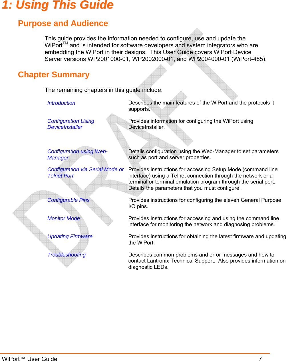

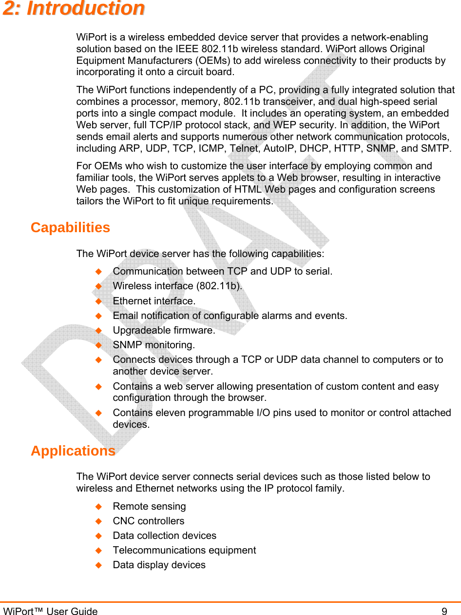
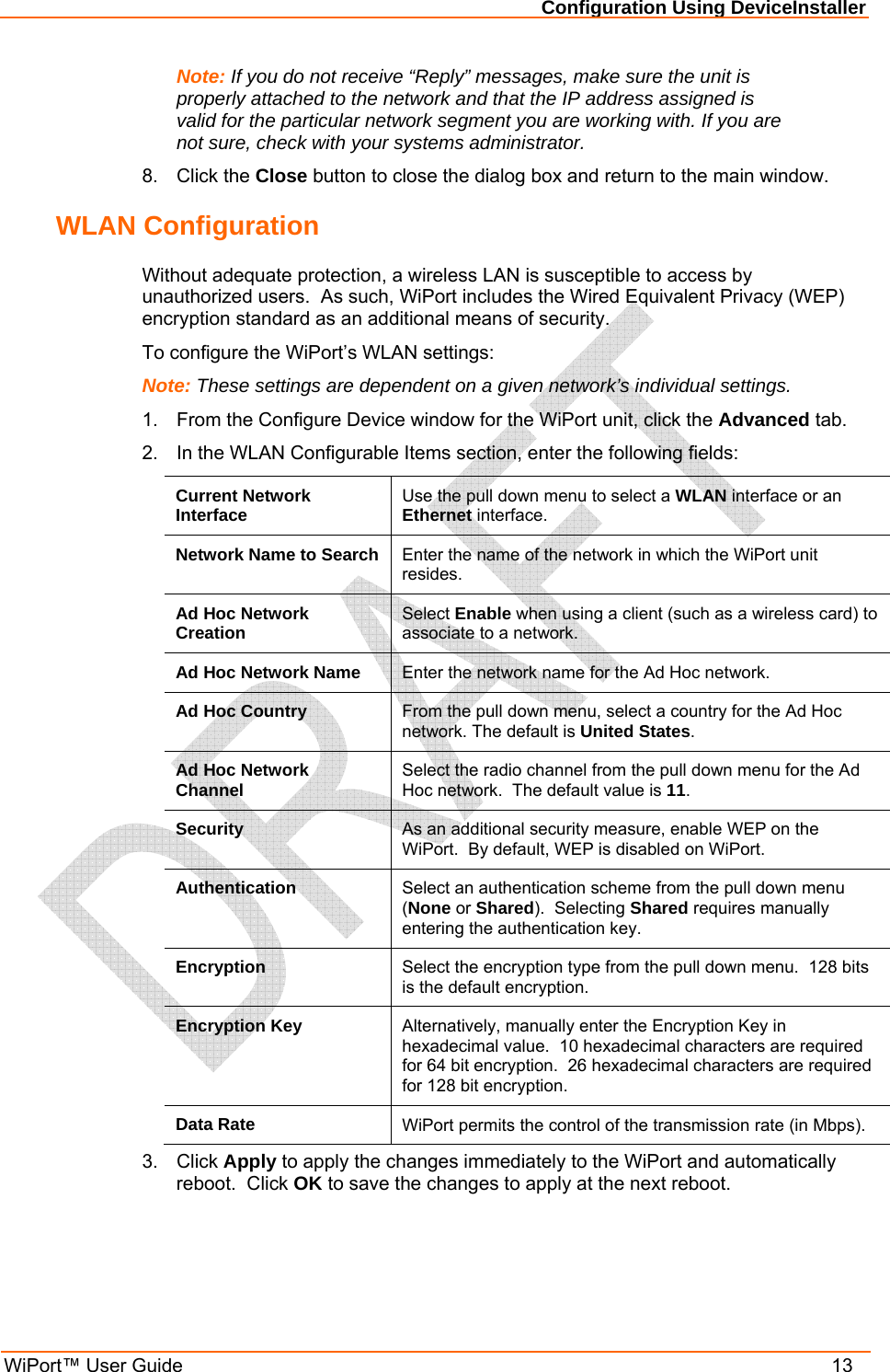
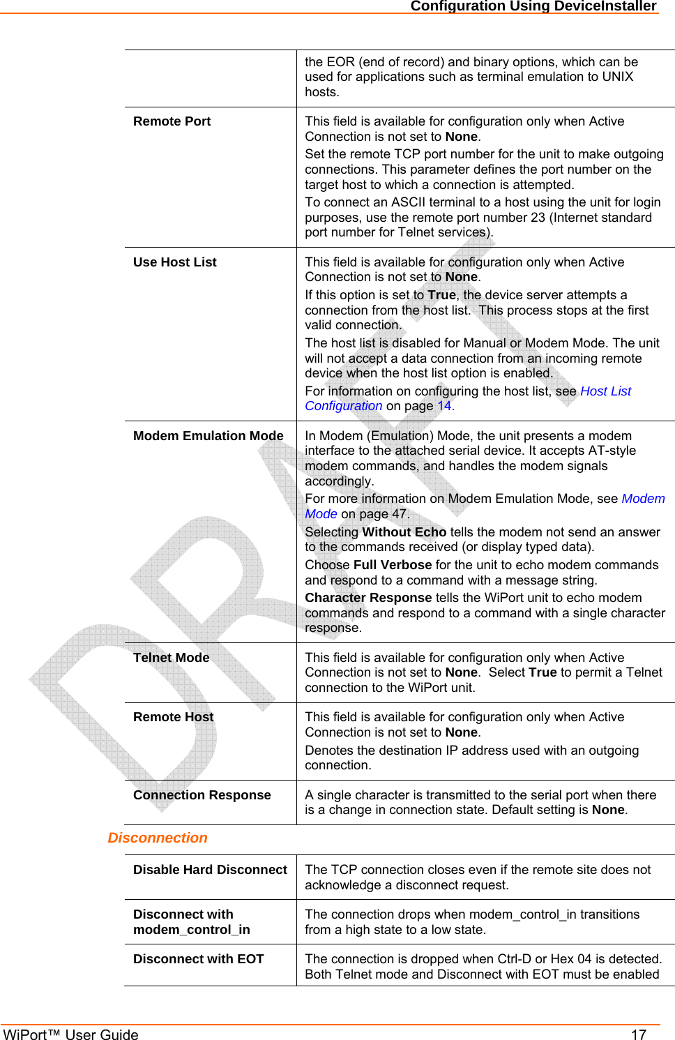
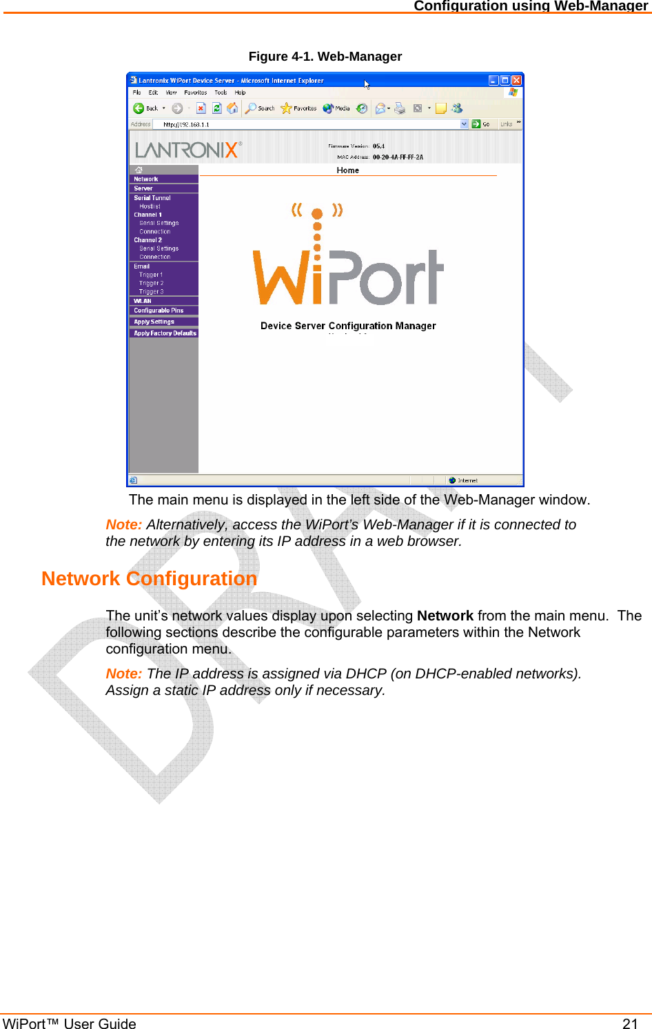
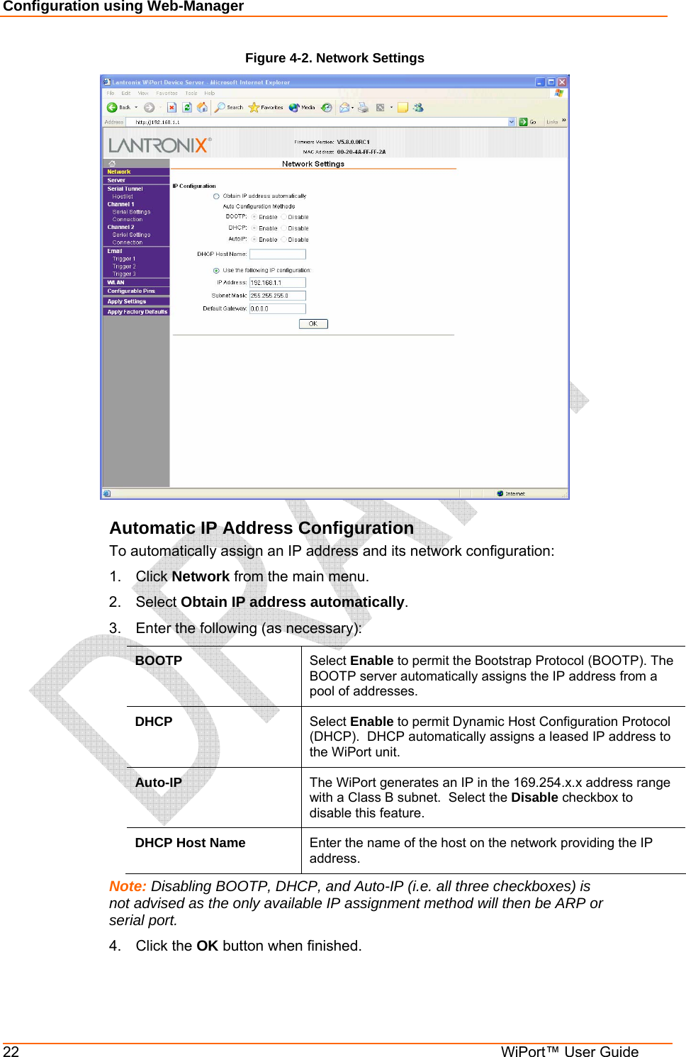
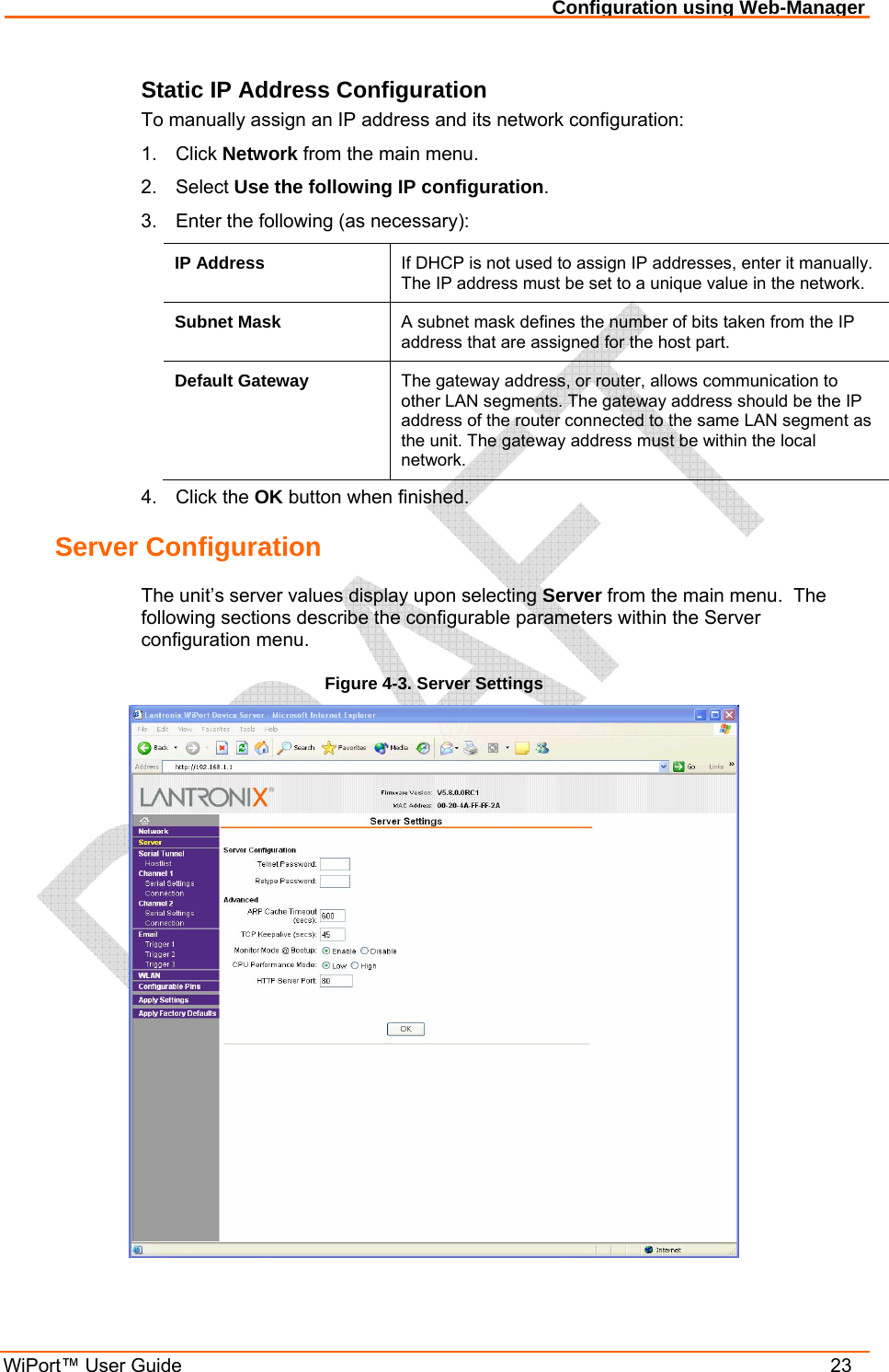
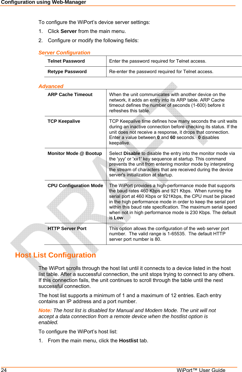
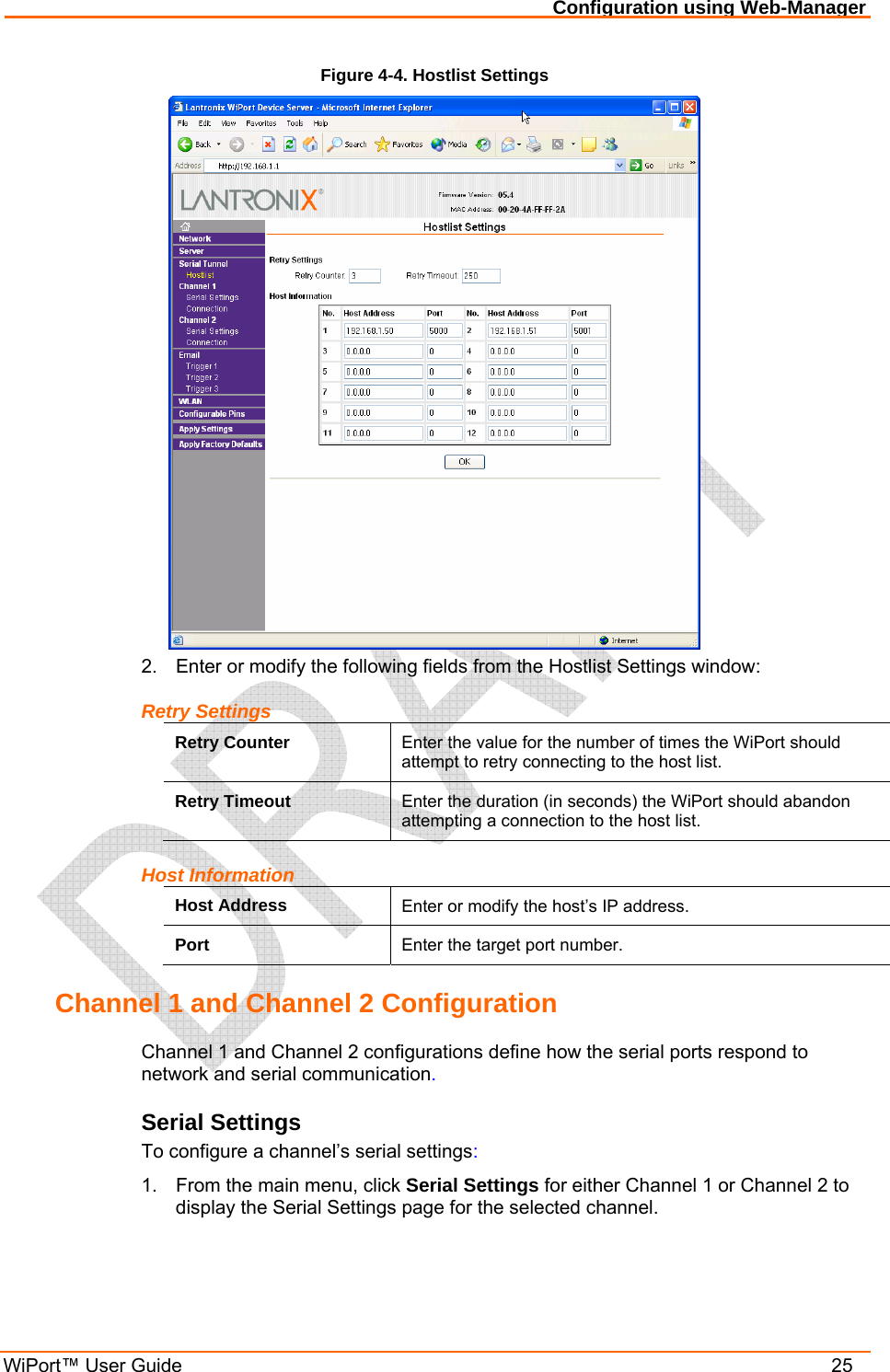
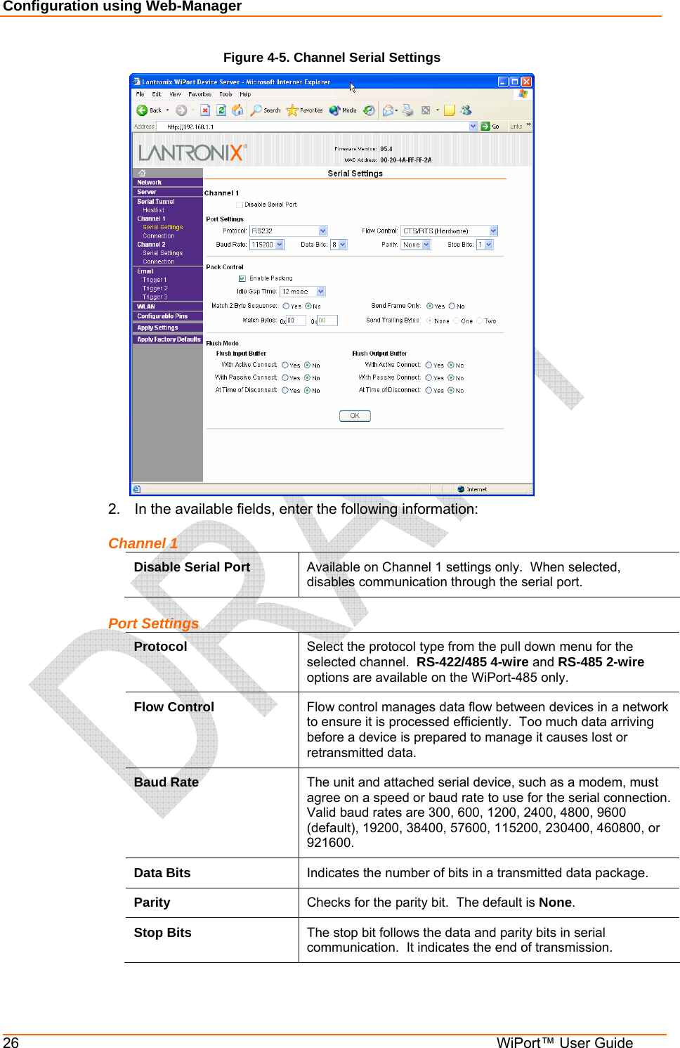
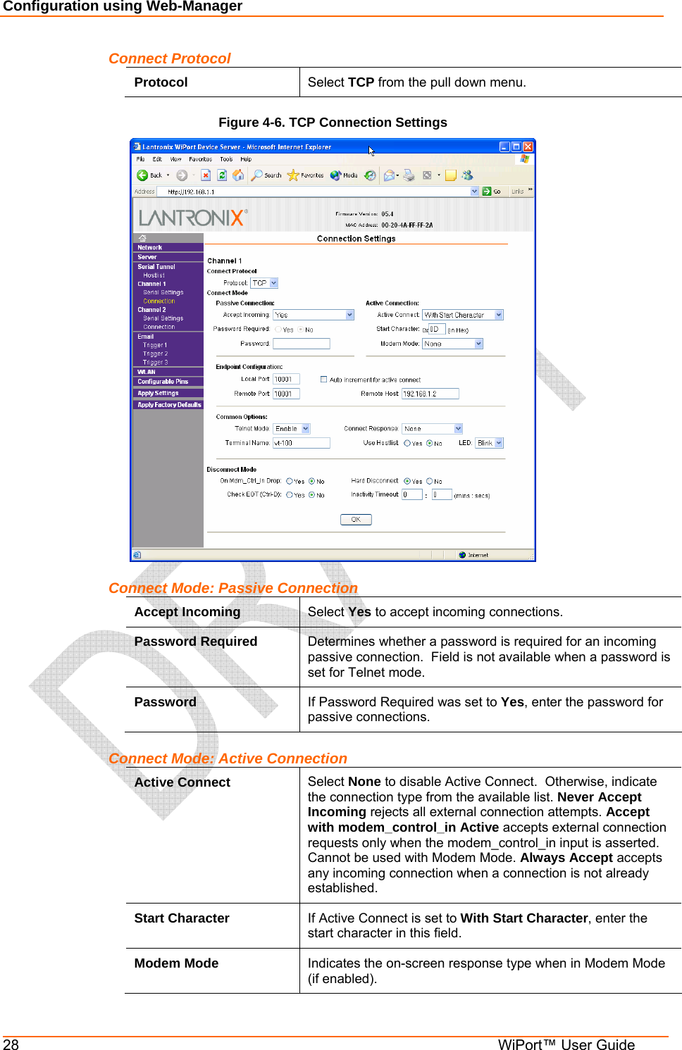
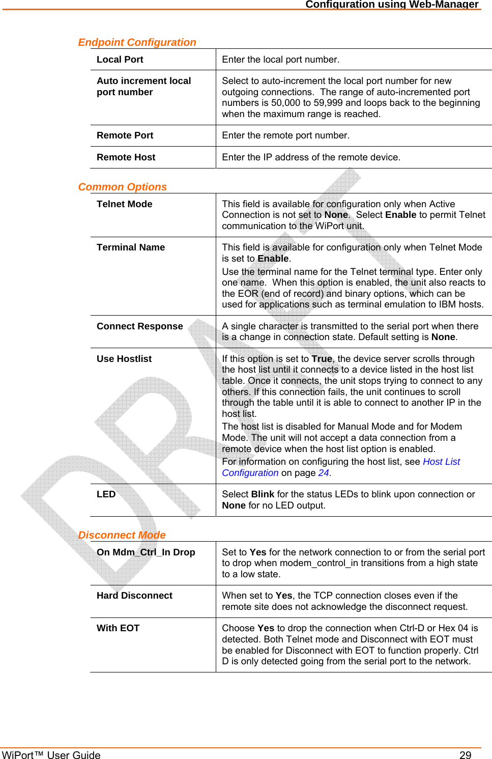
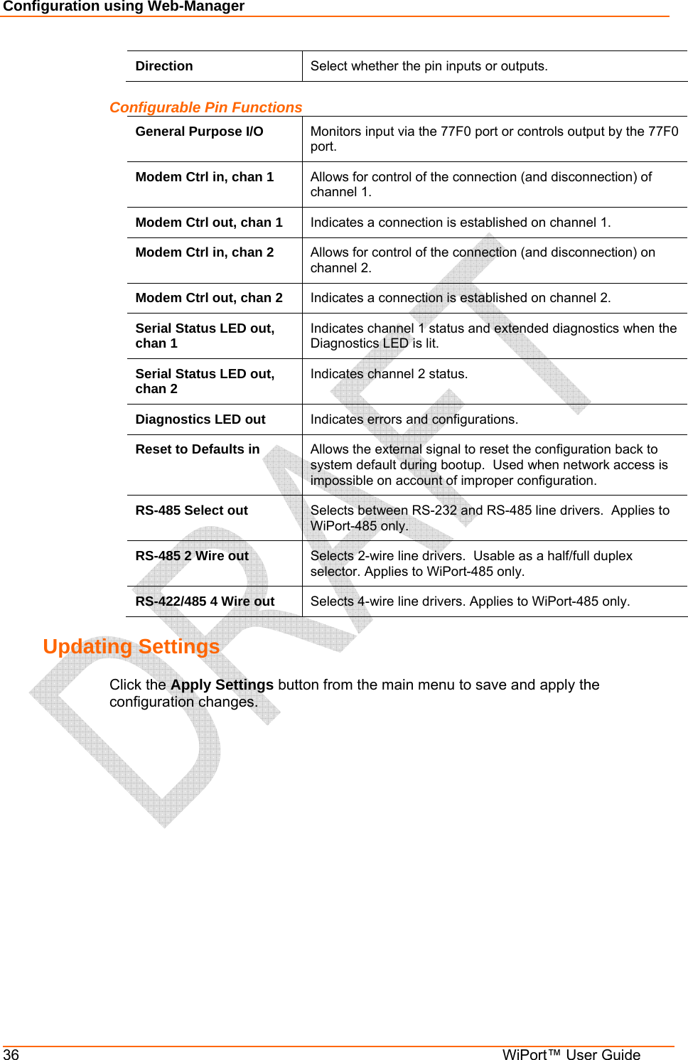
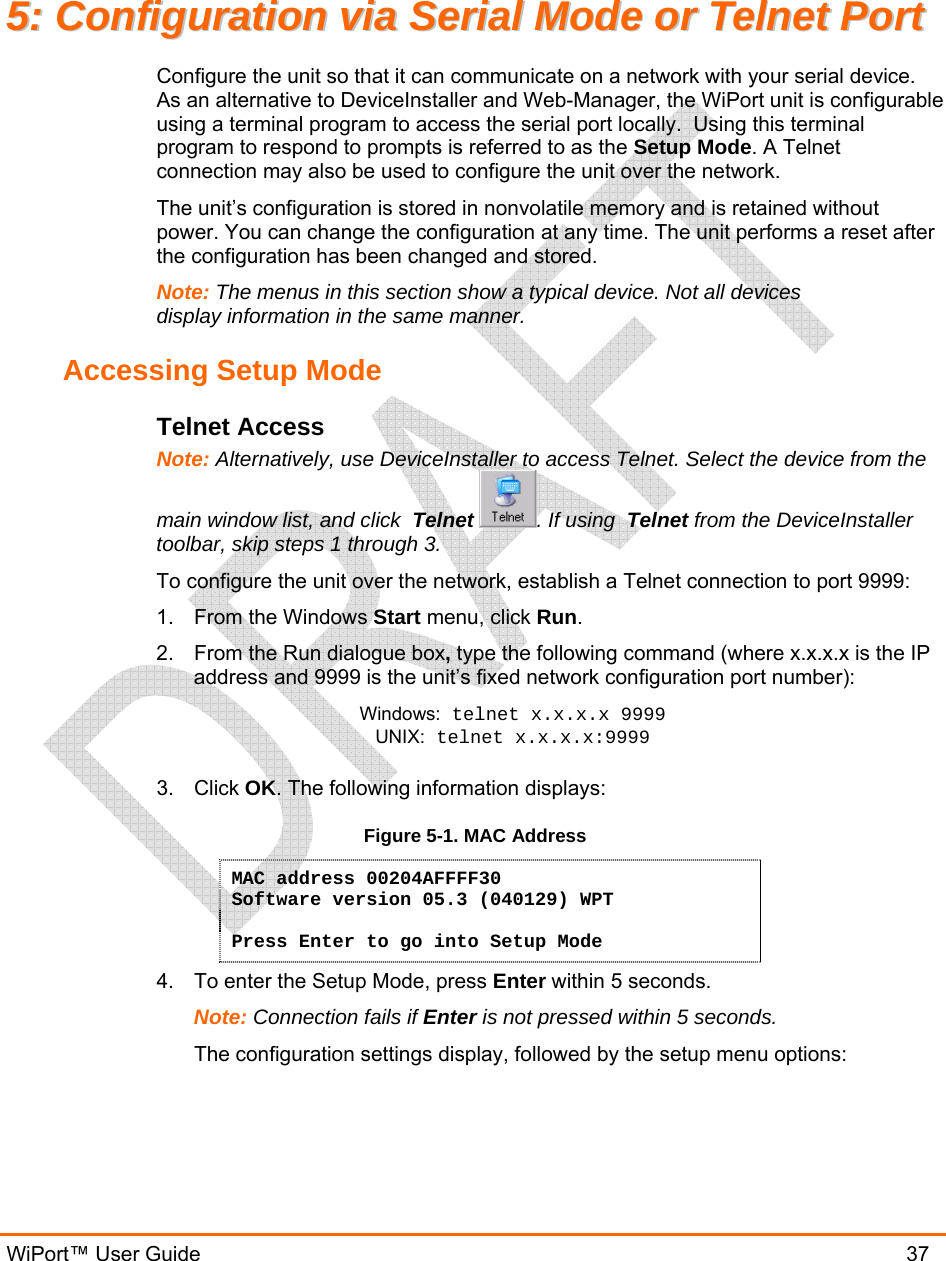
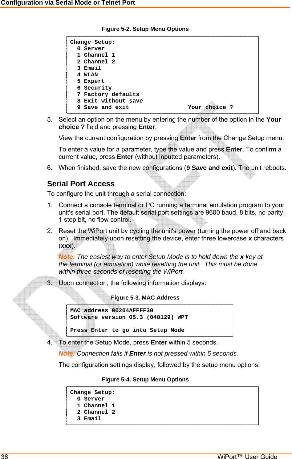
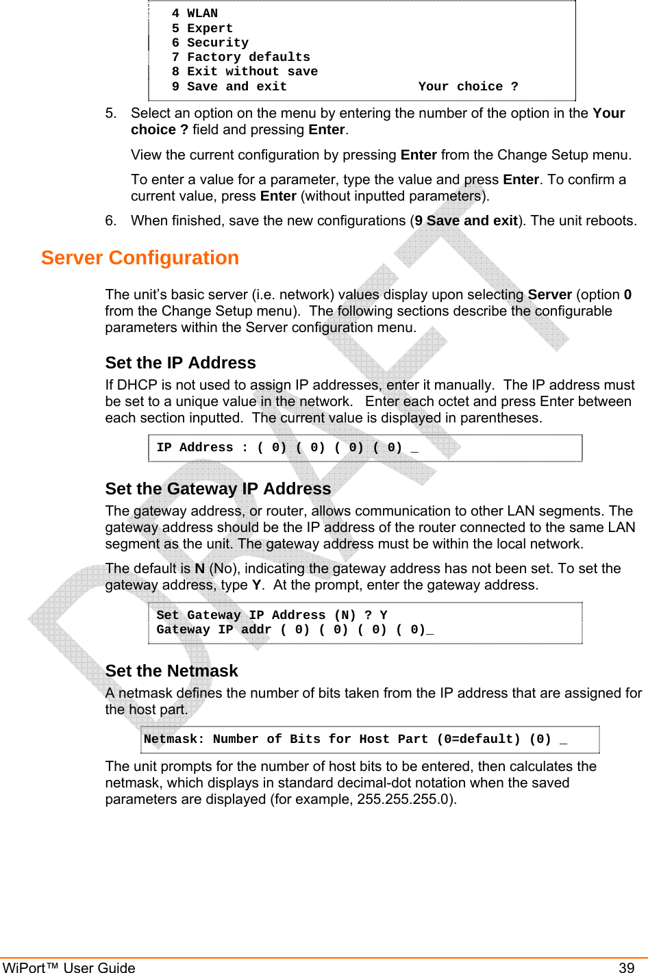
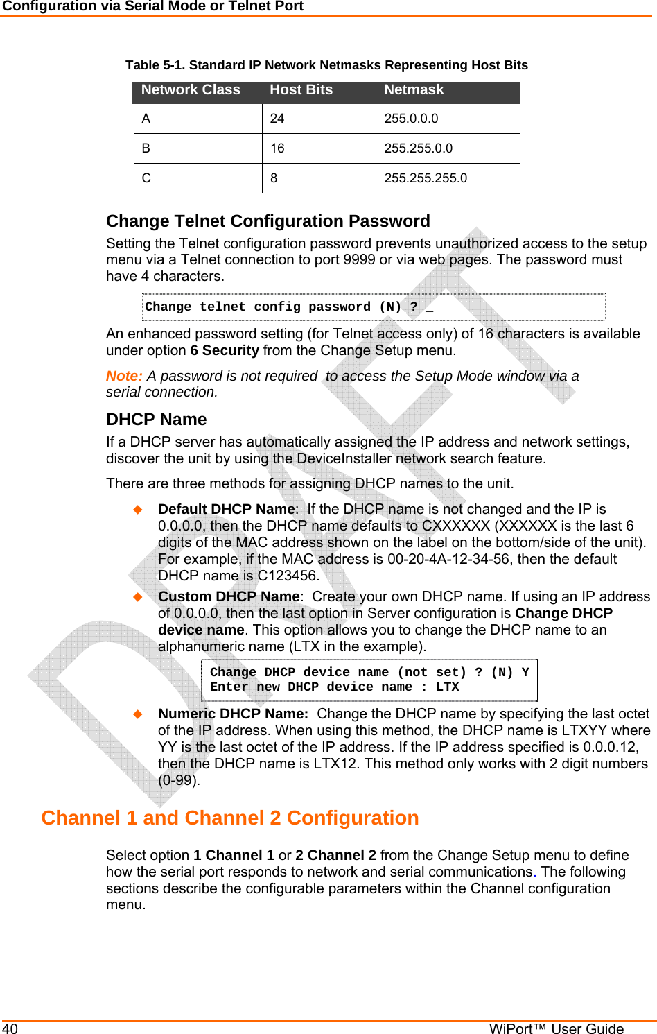
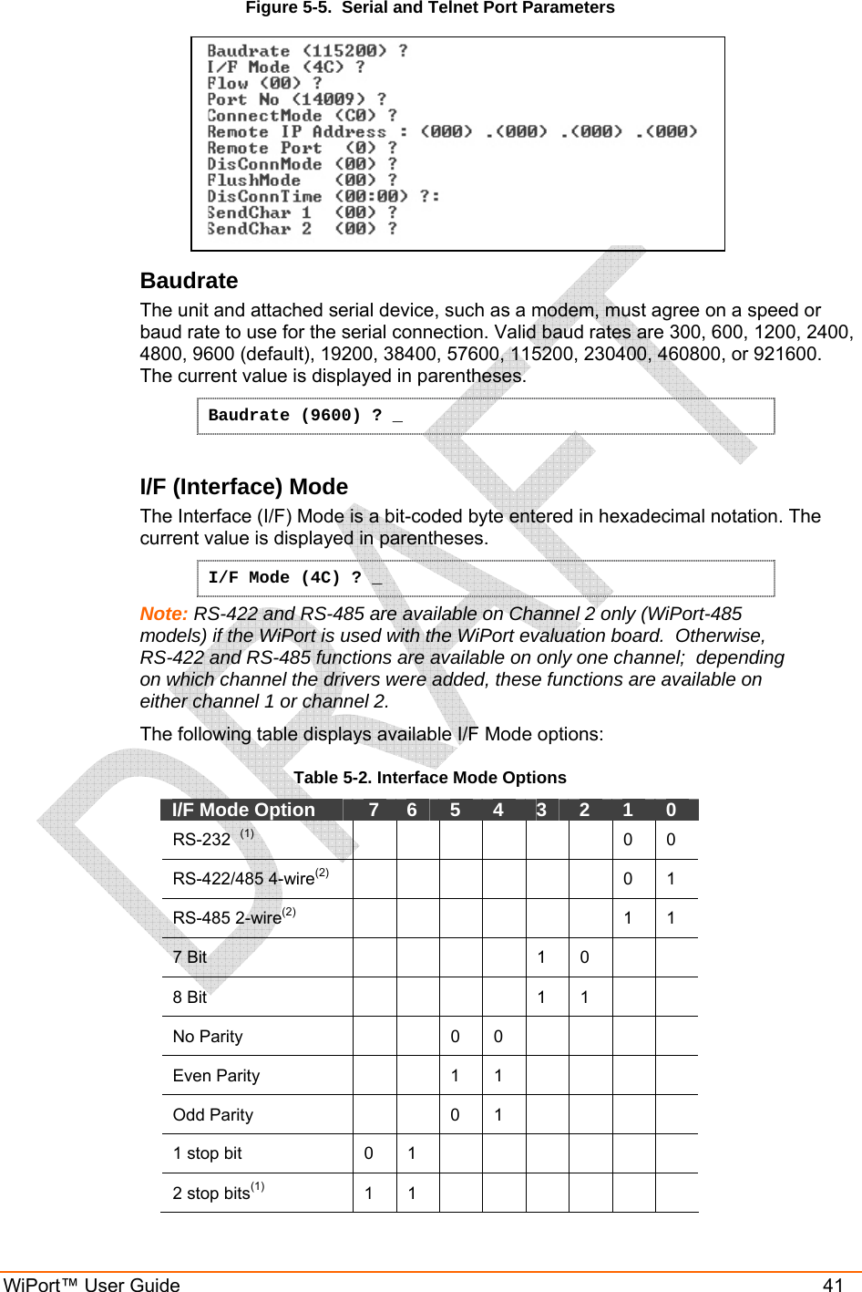
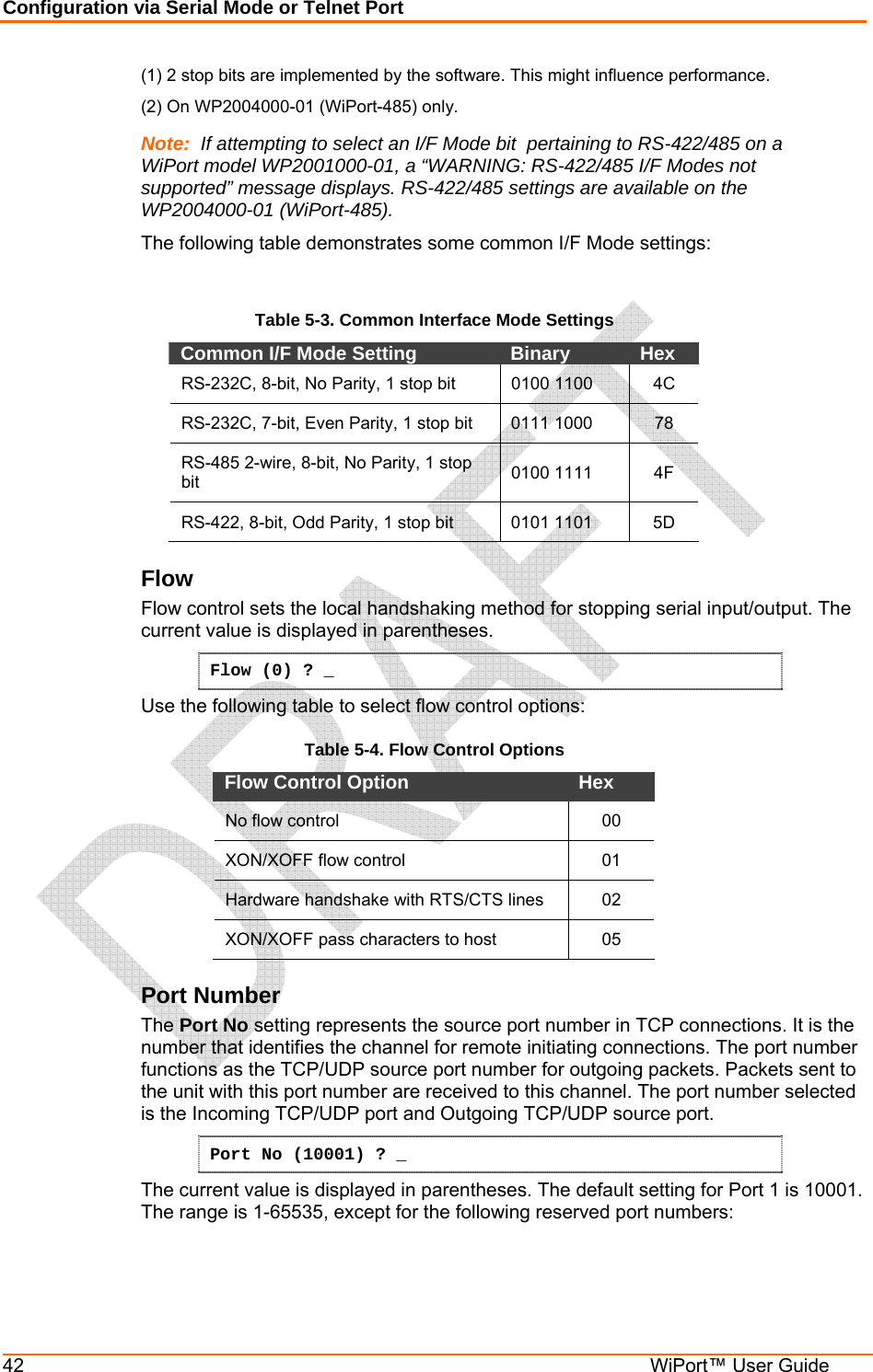
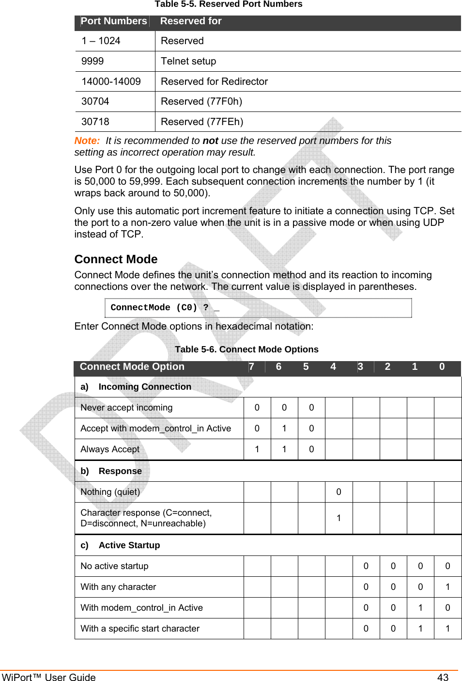
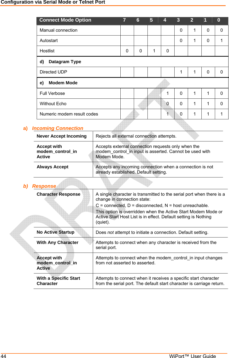
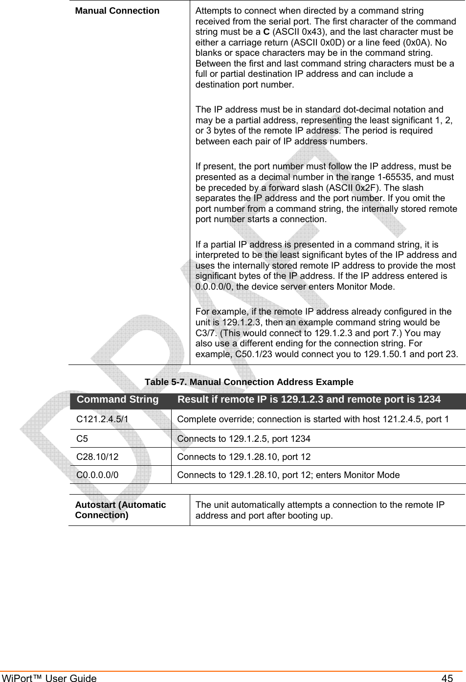
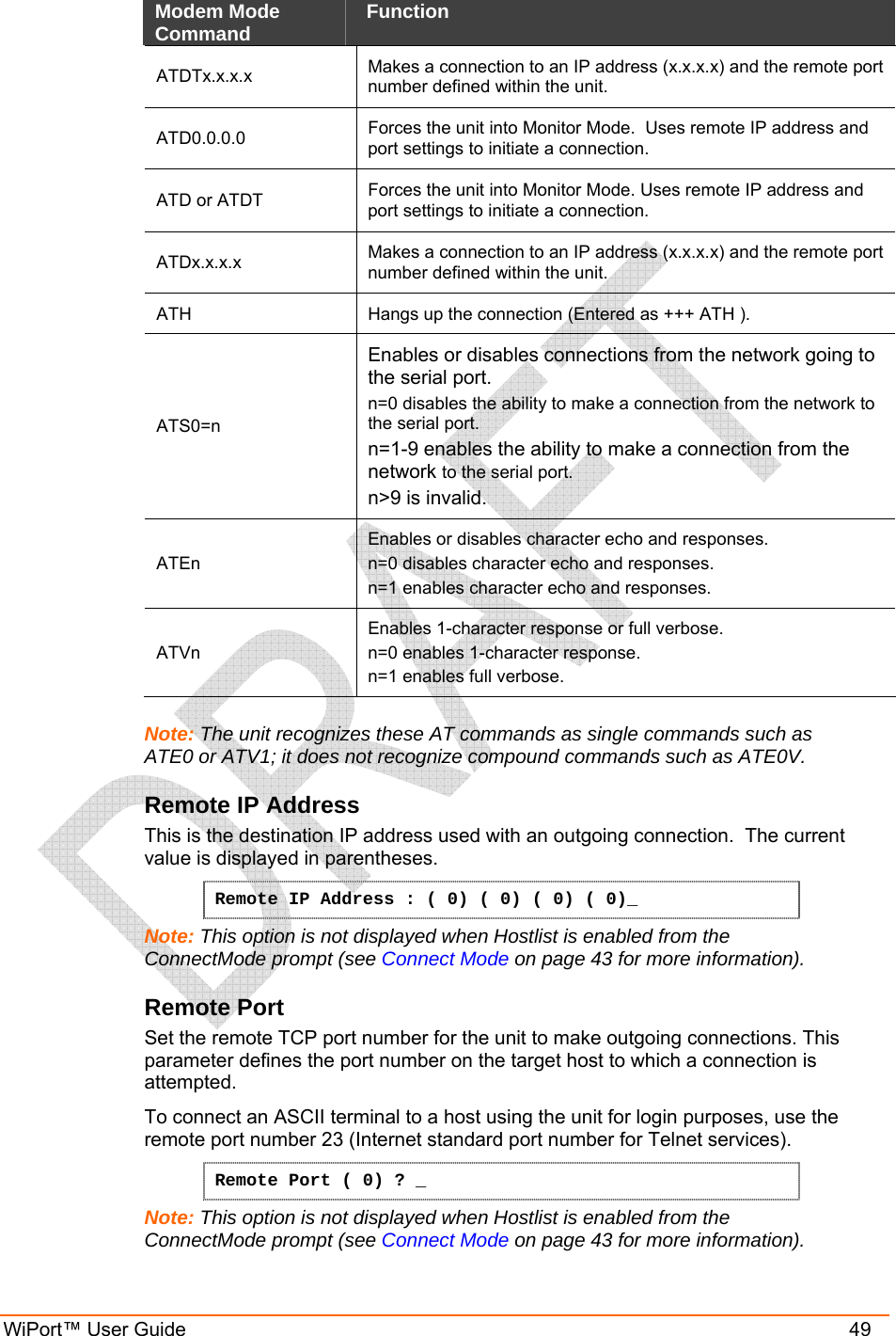
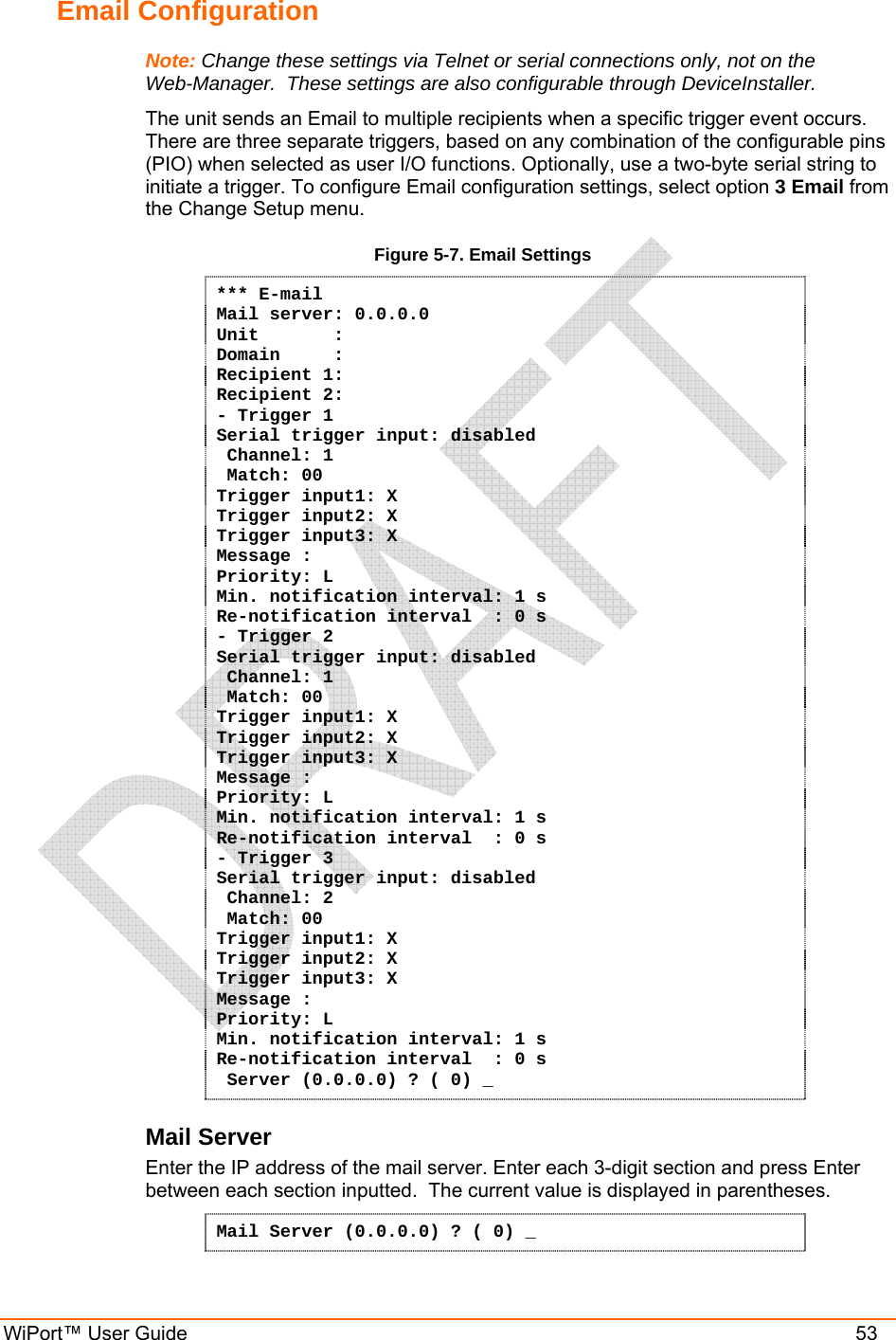
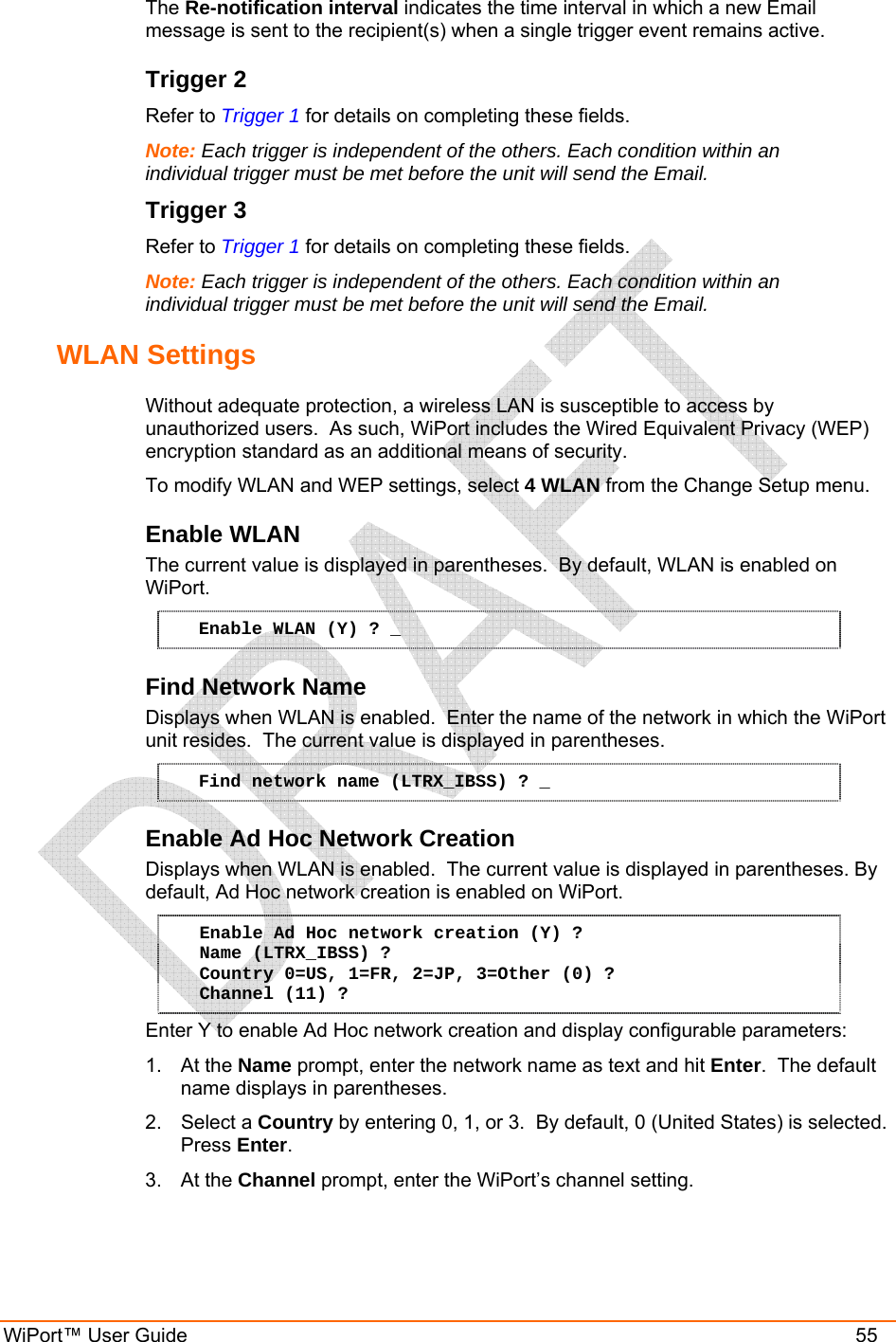
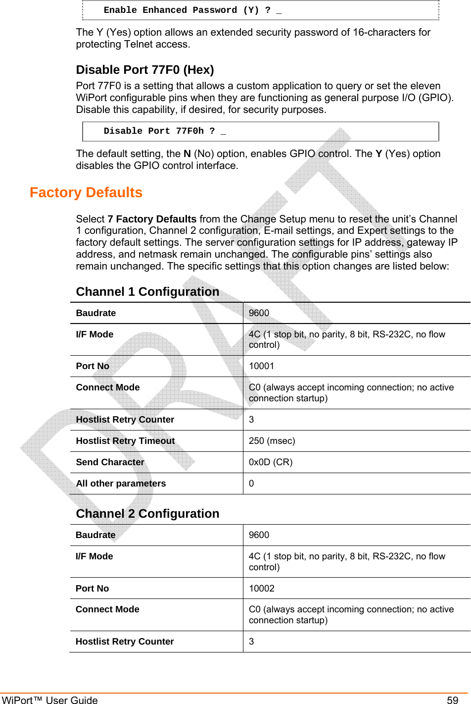
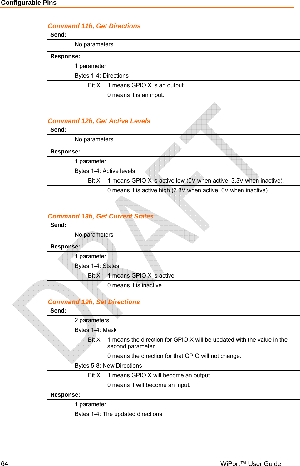
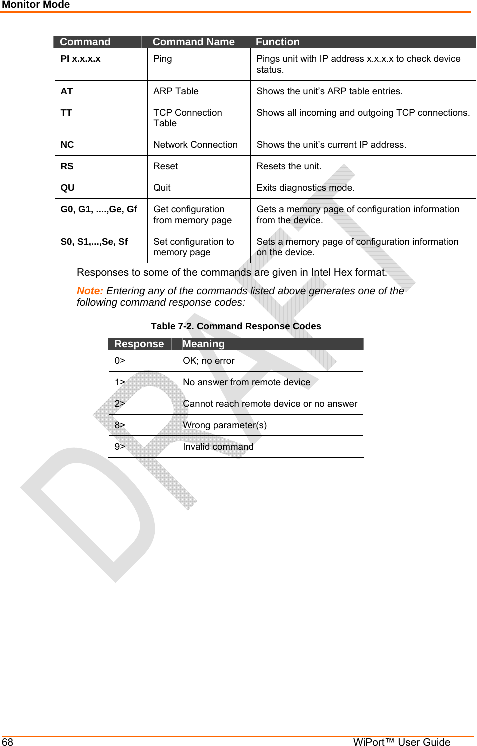
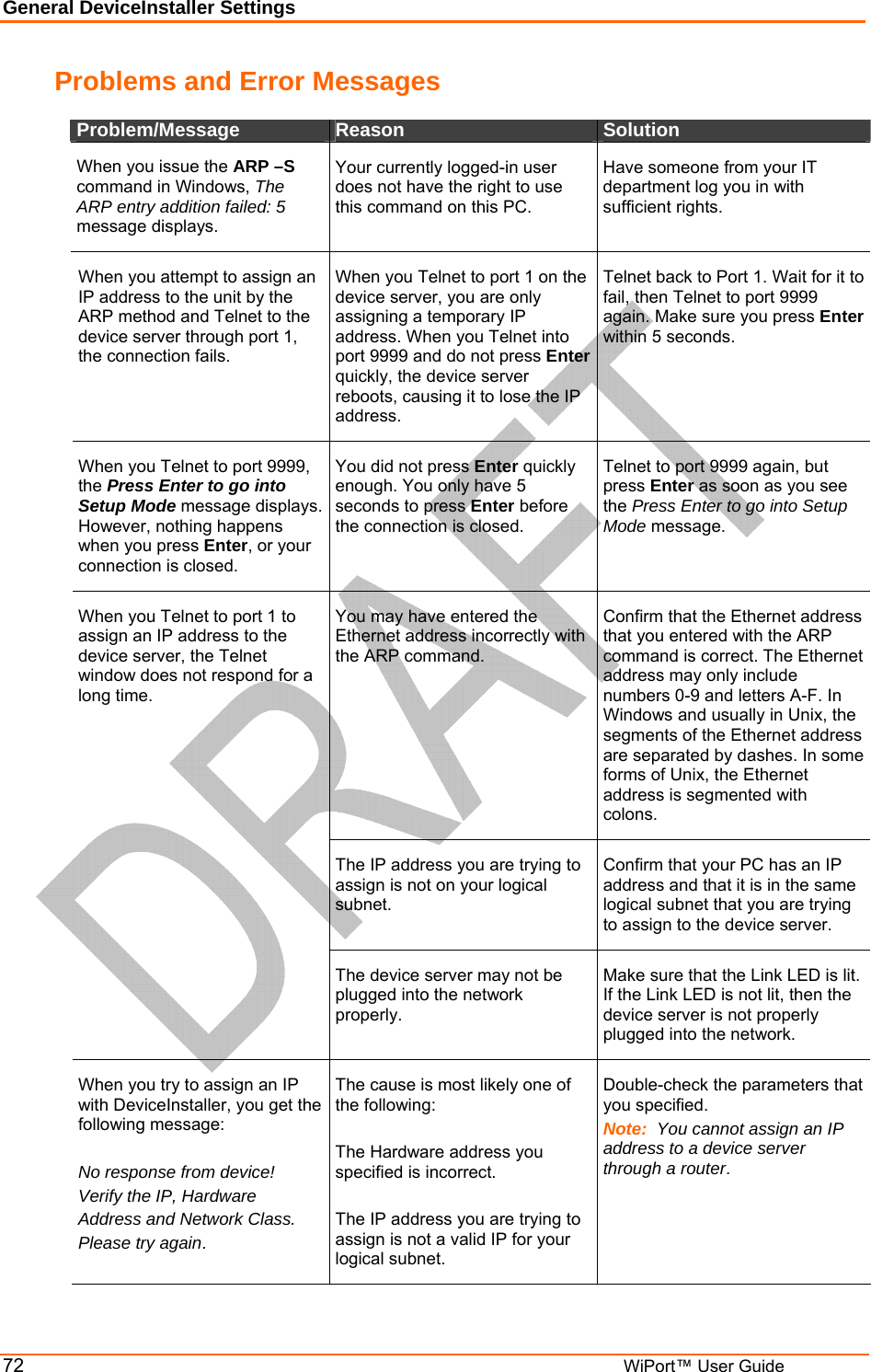
![Configuration via Serial Mode or Telnet Port 54 WiPort™ User Guide Unit Name Enter the username used by the WiPort to send Email messages. The current value is displayed in parentheses. Unit name () ? _ Domain Name Enter the Email server’s domain name. The current value is displayed in parentheses. Domain name () ? _ Recipient 1 Enter the full Email address of the trigger email recipient. The current value is displayed in parentheses. Recipient 1 () ? _ Recipient 2 Enter the full Email address of the trigger email recipient. The current value is displayed in parentheses. Recipient 2 () ? _ Trigger 1 A trigger event occurs when the unit receives the specified trigger input as a result of a specified combination of conditions on the configurable pins. Enable serial trigger input (N) ? Trigger input1 [A/I/X] (X) ? Trigger input1 [A/I/X] (X) ? Trigger input1 [A/I/X] (X) ? Message () ? Priority (L) ? Minimum notification interval (1 s) ? Re-notification interval (0 s) ? Set the configurable pins to A = Active, I = Inactive, or X = Don’t Care. Active can mean Active Low or Active High. If the configurable pins are all set to X (Don’t Care), then they are disabled. If both the serial sequence and the configurable pins are disabled, the trigger is disabled. To change the configurable pins’ settings, you must use DeviceInstaller or send setup records to Port 77FE. The Message is the subject line of the trigger event Email to the specified recipient(s). The Priority is the priority level for the trigger even Email. Enter L for normal priority or H for high priority. The Minimum notification interval is the minimum time allowed between individual triggers. If a trigger event occurs within the minimum interval since the last trigger, it is ignored.](https://usermanual.wiki/lantronix/WIPORT/User-Guide-505512-Page-54.png)